t h e m agaz i n e o f t ec h n o lo gy i n s i d …johnross.com/ieee_spectrum_feb_2009.pdf ·...
TRANSCRIPT
02.09
T H E M A G A Z I N E O F T E C H N O L O G Y I N S I D E R S
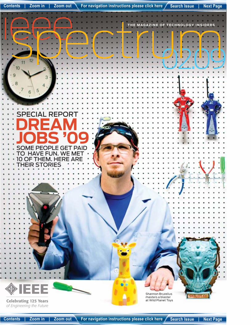
SPECIAL REPORT
DREAM JOBS ’09
Shannon Bruzelius masters a blaster at Wild Planet Toys
SOME PEOPLE GET PAID
TO HAVE FUN. WE MET
10 OF THEM. HERE ARE
THEIR STORIES
Contents | Zoom in | Zoom out For navigation instructions please click here Search Issue | Next Page
Contents | Zoom in | Zoom out For navigation instructions please click here Search Issue | Next Page
6 NA • IEEE SPECTRUM • FEBRUARY 2009 WWW.SPECTRUM.IEEE.ORG
IEEE MEDIA
STAFF DIRECTOR; PUBLISHER, IEEE SPECTRUM
James A. Vick, [email protected]
ASSOCIATE PUBLISHER, SALES & ADVERTISING DIRECTOR Marion Delaney, [email protected]
RECRUITMENT SALES DEVELOPMENT MANAGER
Michael Buryk, [email protected]
BUSINESS MANAGER Robert T. Ross
MARKETING & PROMOTION MANAGER Blanche McGurr, [email protected]
INTERACTIVE MARKETING MANAGER Ruchika Anand, [email protected]
LIST/RECRUITMENT MARKETING MANAGER Ilia Rodriguez, [email protected]
REPRINT SALES +1 212 221 9595, EXT. 319
DEPARTMENT ADMINISTRATOR Faith H. Jeanty, [email protected]
ADVERTISING SALES +1 212 419 7760
TELEPHONE ADVERTISING/SALES REPRESENTATIVE
John Restchack +1 212 419 7578
ADVERTISING PRODUCTION MANAGER Felicia Spagnoli
SENIOR ADVERTISING PRODUCTION COORDINATOR Nicole Evans
ADVERTISING PRODUCTION +1 732 562 6334
IEEE STAFF EXECUTIVE, PUBLICATIONS Anthony Durniak
IEEE BOARD OF DIRECTORS
PRESIDENT & CEO John R. Vig +1 732 562 3928 FAX: +1 732 465 6444 [email protected]
PRESIDENT-ELECT Pedro A. Ray
TREASURER Peter W. Staecker
SECRETARY Barry L. Shoop
PAST PRESIDENT Lewis M. Terman
VICE PRESIDENTS
Teofi lo Ramos, Educational Activities; Jon G. Rokne, Publication Services & Products; Joseph V. Lillie, Member & Geographic Activities; W. Charlton Adams, President, Standards Association; Harold L. Flescher, Technical Activities; Gordon W. Day, President, IEEE-USA
DIVISION DIRECTORS
Giovanni De Micheli (I); Robert E. Hebner Jr. (II); Curtis A. Siller Jr. (III); Roger W. Sudbury (IV); Deborah M. Cooper (V); Mark I. Montrose (VI); John D. McDonald (VII); Stephen L. Diamond (VIII); Frederick C. Mintzer (IX); Richard A. Volz (X)
REGION DIRECTORS
Howard E. Michel (1); William P. Walsh Jr. (2); William B. RatcliE (3); Don C. Bramlett (4); David J. Pierce (5); Leonard J. Bond (6); Ferial El-Hawary (7); Jozef W. Modelski (8); Enrique E. Alvarez (9); Yong Jin Park (10)
DIRECTORS EMERITUS
Eric Herz, Theodore W. Hissey
IEEE STAFF
HUMAN RESOURCES Betsy Davis, SPHR +1 732 465 6434, [email protected]
PUBLICATIONS Anthony Durniak +1 732 562 3998, [email protected]
EDUCATIONAL ACTIVITIES Douglas Gorham +1 732 562 5483, [email protected]
STANDARDS ACTIVITIES Judith Gorman +1 732 562 3820, [email protected]
MEMBER & GEOGRAPHIC ACTIVITIES Cecelia Jankowski +1 732 562 5504, [email protected]
CORPORATE STRATEGY & COMMUNICATIONS Matthew Loeb, CAE +1 732 562 5320, [email protected]
BUSINESS ADMINISTRATION Richard D. Schwartz +1 732 562 5311, [email protected]
TECHNICAL ACTIVITIES Mary Ward-Callan +1 732 562 3850 , [email protected]
MANAGING DIRECTOR, IEEE-USA Chris Brantley +1 202 530 8349, [email protected]
IEEE PUBLICATION SERVICES & PRODUCTS BOARD
Jon G. Rokne, Chair; Tayfun Akgul, Tariq S. Durrani, Mohamed E. El-Hawary, Gerald L. Engel, Gerard H. Gaynor, Marion O. Hagler, Jens Hannemann, Lajos Hanzo, Hirohisa Kawamoto, Michael R. Lightner, Lloyd A. Morley, William W. Moses, Adrian V. Pais, Saifur Rahman, Sorel Reisman, Edward A. Rezek, Barry L. Shoop, W. Ross Stone, Robert J. Trew, Leung Tsang, Karl R. Varian, Stephen Yurkovich
IEEE OPERATIONS CENTER
445 Hoes Lane, Box 1331, Piscataway, NJ 08854-1331 U.S.A. Tel: +1 732 981 0060 Fax: +1 732 981 1721
CL
OC
KW
ISE
FR
OM
TO
P L
EF
T:
PE
G S
KO
RP
INS
KI;
MIT
CH
EL
L W
EIS
S;
RO
SS
KIR
TO
N;
TH
E L
UK
AS
ZE
WS
KI
GR
OU
P;
ZA
NN
A
RANDY H. KATZ,
an IEEE Fellow, is a
professor of
electrical
engineering and
computer science at the University
of California, Berkeley. His
current interest is the
architecture of Internet data
centers. In “Tech Titans Building
Boom” [p. 40], he describes how
engineers are increasing the
density of servers in a facility by
more than tenfold. He’s still
trying to get a peek at Google’s
mega data center in Oregon.
ROSS KIRTON
photographed sound
engineer Marco
Migliari, backed by
progressive Brit-rock
band the Moonfi sh, for Dream Jobs
[p. 24]. “We didn’t want it to look like
Marco was the band’s manager,”
Kirton says, so he placed Migliari in
front of the mixing board, with the
musicians on a platform behind him.
The London-based photographer’s
work has appeared in the UK
editions of Vogue, GQ, and Vanity Fair.
JAMES E.
LUKASZEWSKI
explores the chal-
lenges of relating to
upper management in
“Managing Your Boss’s Boss” [p. 17].
A corporate consultant and author of
Why Should the Boss Listen to You?
The Seven Disciplines of the Trusted
Strategic Advisor (Jossey-Bass, 2008),
he coaches IEEE’s incoming
volunteer leadership each year.
THE MOONFISH
took a three-day break
from its Italian tour to
come to England for a
photo session with the
band’s sound engineer Marco
Migliari [p. 24]. Bassist and singer
Gadi says Migliari is “like a fi fth
member of the band. He understands
us and pinpoints our ideas, which a
producer needs to do with a bunch of
messy lads like us!” For more on the
band, go to http://www.myspace.
com/themoonfi sh.
JOHN ROSS & RICHARD
SCHNEIDER explain why this
month’s planned conversion to
all-digital television broadcasts
in the United States has sparked
a revolution in antenna design.
Ross, an IEEE senior member
and coauthor of “Antennas for the
New Airwaves” [p. 44], consults
on antenna design and RF electro-
magnetics. His home antenna is an
old prototype ClearStream1 that sits
on a bookshelf and receives 24 digital
stations from the Salt Lake City area.
Coauthor Schneider, president and
founder of St. Louis–based Antennas
Direct, uses a ClearStream4 antenna
mounted on his roof to receive
over 20 stations, including a half
dozen from Columbia, Mo., some
160 kilometers away.
GISELLE WEISS
is a freelance writer
based in Basel,
Switzerland. In
Dream Jobs, she
profi les Philippe Lauper, project
manager for a team building a
solar-powered airplane designed to
circumnavigate the globe [p. 38].
This is the second time that Weiss
has written about the project for
IEEE Spectrum. In 2004, she
interviewed one of its leaders
shortly after the eH ort got under
way. Back then, she says, “You could
actually get [cofounder] Bertrand
Piccard at home at night on the
phone.” These days the project is a
bigger, glossier enterprise, but the
challenge of getting the plane in the
air remains—to say nothing of
getting Piccard on the phone.
______
_________
________
________
________
_________
_______
________
_______
________
_________
________
_________
_______
_________
___________
_________
___________
_____________
Previous Page | �ontents | Zoom in | Zoom out | Front �over | Search Issue | Next Page�� B
�
M Sa�EF
Previous Page | �ontents | Zoom in | Zoom out | Front �over | Search Issue | Next Page�� B
�
M Sa�EF
44 NA • IEEE SPECTRUM • FEBRUARY 2009 WWW.SPECTRUM.IEEE.ORG
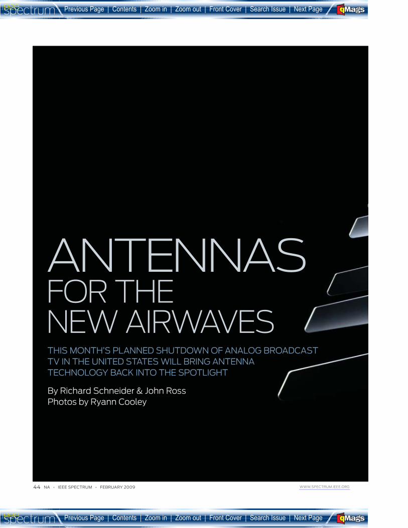
THIS MONTH’S PLANNED SHUTDOWN OF ANALOG BROADCAST
TV IN THE UNITED STATES WILL BRING ANTENNA
TECHNOLOGY BACK INTO THE SPOTLIGHT
By Richard Schneider & John Ross
Photos by Ryann Cooley
ANTENNAS FOR THE
NEW AIRWAVES
_____________
Previous Page | �ontents | Zoom in | Zoom out | Front �over | Search Issue | Next Page�� B
�
M Sa�EF
Previous Page | �ontents | Zoom in | Zoom out | Front �over | Search Issue | Next Page�� B
�
M Sa�EF
FEBRUARY 2009 • IEEE SPECTRUM • NA 45 WWW.SPECTRUM.IEEE.ORG
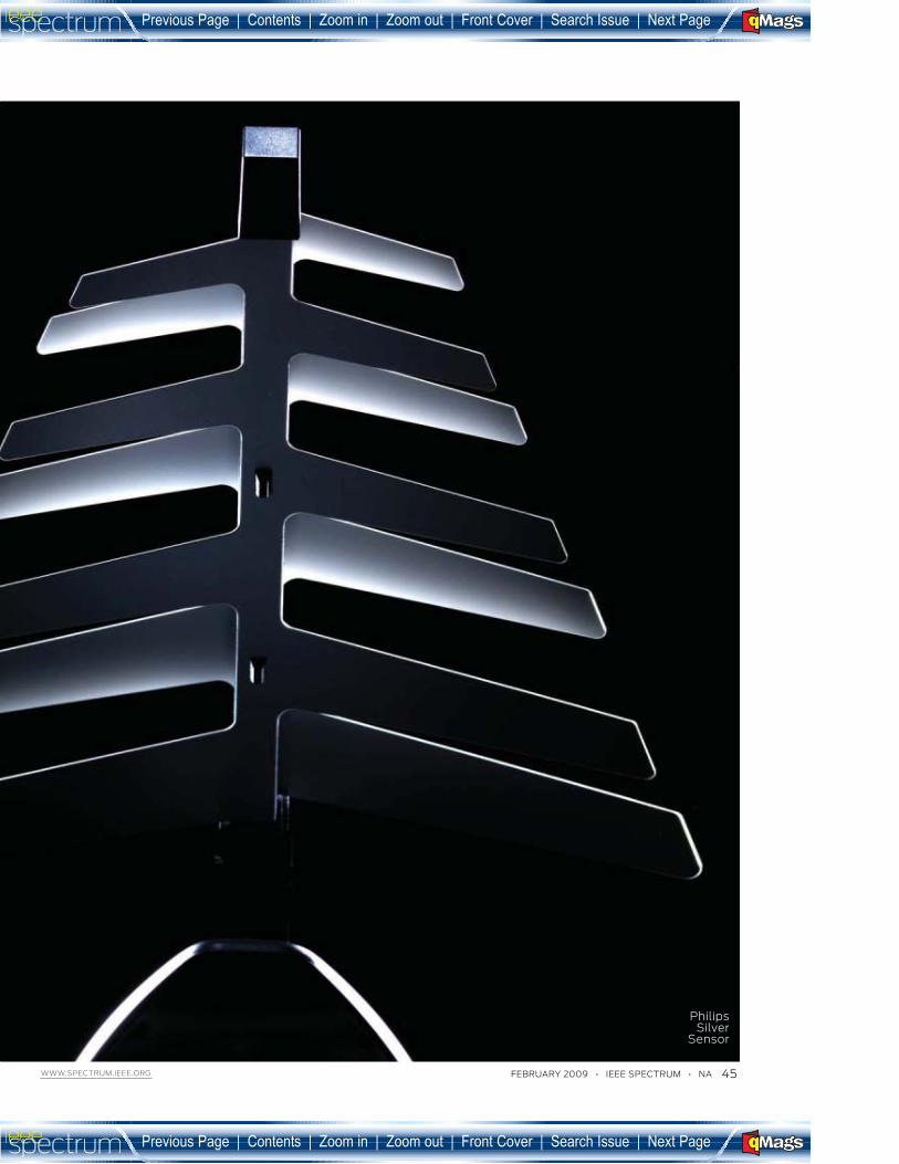
Philips Silver
Sensor
_____________
Previous Page | �ontents | Zoom in | Zoom out | Front �over | Search Issue | Next Page�� B
�
M Sa�EF
Previous Page | �ontents | Zoom in | Zoom out | Front �over | Search Issue | Next Page�� B
�
M Sa�EF

46 NA • IEEE SPECTRUM • FEBRUARY 2009 WWW.SPECTRUM.IEEE.ORG
Let’s say you’ve gone and bought a high-
defi nition LCD TV that’s as big as your out-
stretched arms. And perhaps you’ve also
splurged on a 7.1 channel surround sound system,
and an upconverting DVD player or maybe a sleek
Blu-ray player. Maybe you’ve got a state-of-the-art
game console or Apple TV or some other Web-based
feed. Well, come 17 February, you just might want
one more thing: a new antenna on your roof.
If you live in the United States and
you’re one of the 19 million people who
still prefer to pull their TV signals out of
the air rather than pay a cable company
to deliver them, you may already know
that this month the vast majority of ana-
log television broadcasts in the United
States are scheduled to end and most free,
over-the-air TV signals will be trans-
mitted only in the new digital Advanced
Television Systems Committee (ATSC)
format. A massive advertising campaign
is now telling people who get their sig-
nals from the ether that they’ll need a
TV with a built-in ATSC tuner or a digi-
tal converter box to display their favor-
ite programs.
What the ads don’t mention is that
most of those people will also need a new
antenna. For the vast majority of you out
there in Broadcast-TV Land, the quality of
what you see—or even whether you get a
picture at all—will depend not on your TV
or converter box but on the antenna that
brings the signal to them.
If you have a cable or satellite hookup,
you might think that this antenna issue is
irrelevant—but think again. Some owners
of high-end systems complain that the sig-
nals coming from their satellite or cable
provider aren’t giving them the picture
quality they expected. That’s because
cable and satellite operators often use
lossy compression algorithms to squeeze
more channels, particularly local chan-
nels, into their allotted bandwidth. This
compression often results in a picture with
less detail than the corresponding terres-
trial broadcast signal provides. For video-
philes who have already spent a fortune
on their home-theater systems, a couple of
hundred dollars more for a top-of-the-line
antenna obviously makes sense. And of
course, antennas are also good backup for
the times when the cable gets cut or the sat-
ellite system fades out due to rain or snow.
In addition, they serve second TV sets in
houses not wired to distribute signals to
every room.
Suddenly the dowdy TV antenna, a
piece of technolo0 that has changed lit-
tle over the past 30 years, is about to be
the belle of the ball.
Gone, however, are the days when
a large rooftop antenna was a status
symbol. Cellphones and handheld
GPS units have conditioned consumers
to expect reliable wireless services in very
small packages. Such dramatic changes in
consumer preferences—coupled with the
new frequency allocations, channel distri-
butions, and high demand for reliable over-
the-air digital antennas—mean that the
time for new designs has indeed come.
Most TV viewers think of antennas
as simple devices, but you’re tech savvy,
so of course you’d never assume this.
Nevertheless, bear with us briefl y as we
review Antennas 101.
The decades-old designs of most TV
antennas on rooftops—and in the mar-
ket today—are typically confi gured on a
horizontal fi sh bone, with arms of vary-
ing lengths to handle a broad range of
frequencies.Though the engineering of
antennas in other spheres has advanced
radically over the years, manufacturers
of television equipment have stuck pretty
much with the old designs for economic
reasons. Traditional antennas were good
enough for analog television, and the
shrinking customer base for broadcast
reception didn’t o9 er much incentive to
plow money into new designs.
The transition to digital has changed
all that. Most digital channels are
broadcast in UHF, and UHF antennas
are smaller than those used for analog
TV, where most broadcast signals were
VHF. Also, the multipath problem, aris-
ing from signals that refl ect o9 buildings
and hills, which may have occasionally
caused ghosting on analog TVs, can com-
pletely destroy a digital picture.
A few designers and manufacturers
have done the necessary research and
development and introduced improved
models. First out of the labs were the
Silver Sensor, introduced by Antiference,
Winegard SquareShooter
_____________
Previous Page | �ontents | Zoom in | Zoom out | Front �over | Search Issue | Next Page�� B
�
M Sa�EF
Previous Page | �ontents | Zoom in | Zoom out | Front �over | Search Issue | Next Page�� B
�
M Sa�EF
FEBRUARY 2009 • IEEE SPECTRUM • NA 47 WWW.SPECTRUM.IEEE.ORG
based in Coleshill, England, in 2001, and
the SquareShooter, introduced in 2004
by Winegard, in Burlington, Iowa.
The Silver Sensor [see “TV Topper”], an
indoor antenna designed for UHF recep-
tion, is based on the classic log- periodic
design, which means that the electrical
properties repeat periodically with the
logarithm of frequency. Done right, a log-
periodic design o9 ers good performance
over a wide band of frequencies.
The outdoor SquareShooter’s ele-
ment has a sinuous shape, which helps
it respond across a broad UHF range of
frequencies [see “Under the Hood”]. It’s
mounted in front of an open grid that
reflects UHF waves, thereby reducing
the multipath problem by blocking sig-
nals arriving from behind the antenna.
Still, the pace of product introduc-
tions is slow. To this day, some manufac-
turers are still relabeling old designs as
HDTV antennas as long as they generally
cover the right part of the spectrum. But
some very good designs are fi nally on the
market—if you know what to look for.
Antennas are much better now
than they used to be. But two
changes will make them even bet-
ter in the next several years: the intro-
duction of powerful new software tools
for designing antennas, and a slew of
new regulations in the United States that
will reduce the range of frequencies that
a TV antenna must receive. Together,
these factors will lead the way to smaller
antennas [see “Loop de Loop”] that work
better and look better than the apparatus
that sprouted from the roof of your grand-
parents’ house 50 years ago.
The key developments that have
changed antenna design are computa-
tional electro magnetic codes, advanced
search-and-optimization methods like
genetic algorithms, and improved mea-
surement tools such as the vector net-
work analyzer. Traditionally, antenna
designers used pencil and paper to wrestle
with Maxwell’s equations, the four equa-
tions that describe electric and magnetic
fields. Then engineers spent enormous
amounts of time in the laboratory, testing
and tweaking designs. Computational
electro magnetic codes, a breed of program
that solves Maxwell’s equations on a com-
puter, have revolutionized antenna design
by allowing the engineer to simulate the
real-world electromagnetic behavior of an
antenna before it is built.
As computer power increased in the
1990s, antenna engineers began using
automatic search-and-optimization
methods to sort through the successive
designs their codes generated. In partic-
ular, they used genetic algorithms, which
emulate the Darwinian principle of nat-
ural selection through a survival-of-the-
fittest approach. After sifting through
millions of possible design confi gurations,
the algorithm can zoom in on a handful
of promising optimal designs that meet
specifi ed performance and size criteria.
Thanks to these tools, antenna design-
ers can focus more on the antenna itself
and less on the math. And the months that
used to be spent testing prototypes are now
compressed into days—or even just hours—
of simulation. Designers now go to the lab-
oratory only for a fi nal check, to confi rm
the accuracy of their computations.
And in the lab, life is a lot easier today
than it was several decades ago. To check
antenna performance, engineers have to
measure its impedance accurately across
a huge frequency range. That is what a
modern vector network analyzer now lets
them do easily and quickly. Decades ago,
engineers had to calculate, for each chan-
nel’s frequency, the impedance from mea-
surements of voltage signals in the cable
leading to the antenna. This was a labori-
ous and often imprecise process.
Regulations that reduce the
range of frequencies a television
must receive are driving big changes
in antenna design. The new regulations
relax the other two main design constraints,
gain and size, making it possible for smaller
and far less conspicuous antennas than the
monstrosities of yore.
These changes are part of a frequency
reallocation that has turned the various
parties claiming pieces of the radio spec-
trum into players in a game of musical
chairs. In the analog television world, TV
broadcasts occupy three bands. The low-
VHF band covers 54 to 88 megahertz, the
high-VHF band covers 174 to 216 MHz,
and the UHF band covers 470 to 806
MHz. Earlier the UHF band stretched
all the way to 890 MHz, but some of this
bandwidth was given up in the 1980s to
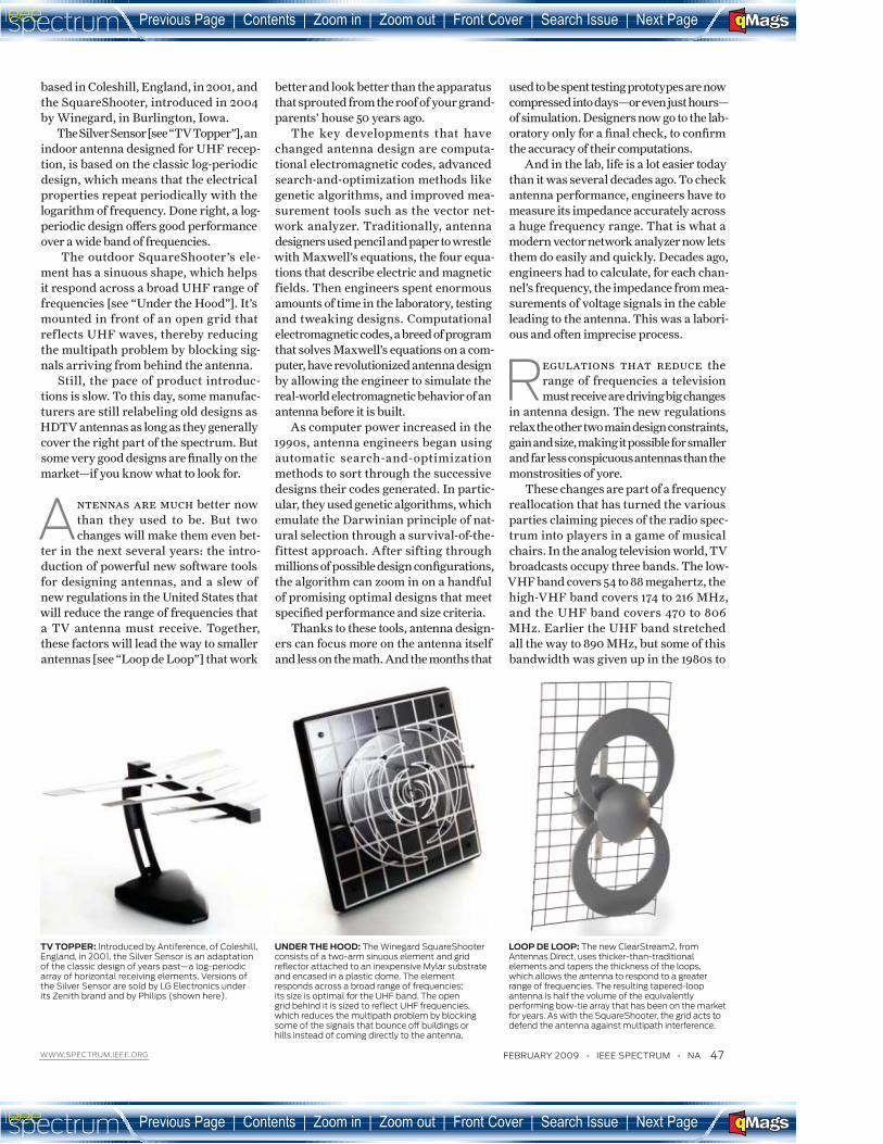
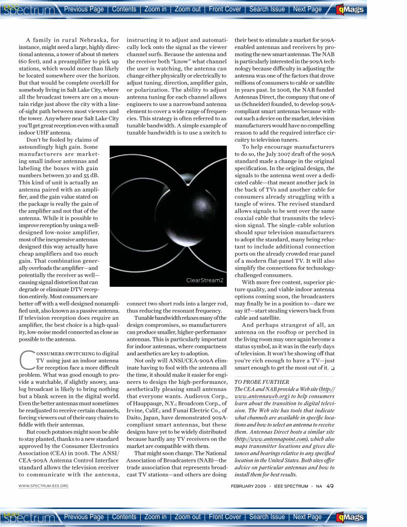
LOOP DE LOOP: The new ClearStream2, from Antennas Direct, uses thicker-than-traditional elements and tapers the thickness of the loops, which allows the antenna to respond to a greater range of frequencies. The resulting tapered-loop antenna is half the volume of the equivalently performing bow-tie array that has been on the market for years. As with the SquareShooter, the grid acts to defend the antenna against multipath interference.
TV TOPPER: Introduced by Antiference, of Coleshill, England, in 2001, the Silver Sensor is an adaptation of the classic design of years past—a log-periodic array of horizontal receiving elements. Versions of the Silver Sensor are sold by LG Electronics under its Zenith brand and by Philips (shown here).
UNDER THE HOOD: The Winegard SquareShooter consists of a two-arm sinuous element and grid refl ector attached to an inexpensive Mylar substrate and encased in a plastic dome. The element responds across a broad range of frequencies; its size is optimal for the UHF band. The open grid behind it is sized to refl ect UHF frequencies, which reduces the multipath problem by blocking some of the signals that bounce oF buildings or hills instead of coming directly to the antenna.
_____________
Previous Page | �ontents | Zoom in | Zoom out | Front �over | Search Issue | Next Page�� B
�
M Sa�EF
Previous Page | �ontents | Zoom in | Zoom out | Front �over | Search Issue | Next Page�� B
�
M Sa�EF
48 NA • IEEE SPECTRUM • FEBRUARY 2009 WWW.SPECTRUM.IEEE.ORG 48 NA • IEEE SPECTRUM • FEBRUARY 2009 WWW.SPECTRUM.IEEE.ORG
provide spectrum for cellphone commu-
nications. The two VHF bands will be
retained in the transition to digital TV,
but the ceiling of the UHF band will be
reduced to 698 MHz, making room for
new wireless services and for applica-
tions involving homeland security. This
is 108 MHz narrower than the current
UHF TV allocations and 192 MHz nar-
rower than the older allocations, which
extended out to channel 83.
Notably, the older and wider UHF
bands were in effect when most of the
TV antennas on the market today were
designed. The old designs are therefore
rarely optimal for the new spectrum allo-
cations because the antennas had to cover
the wider bands and higher frequencies.
The transition to digital has also
changed how the stations are distributed
across the allocated bands. In the days
of analog, most TV stations were on the
VHF band, with smaller, less powerful
stations in the UHF band. But now, in the
fast-approaching digital world, roughly
74 percent of the stations are on the UHF
band and 25 percent are on the high-VHF
band (today’s channels 7 through 13). Only
about 1 percent of the stations will be in the
low-VHF band (channels 2 through 6).
Gain is not the be-all and end-
all of antenna design—far from
it, as any antenna engineer will tell
you. But you’d be hard-pressed to know that
if spec sheets and marketing hype are your
main sources of information.
Gain, usually expressed in decibels,
indicates how well the antenna focuses
ener0 from a particular direction as com-
pared with a standard reference antenna.
Because most spec sheets don’t give a two-
or three-dimensional radiation plot, the
gain number specifi ed is the value in the
direction of maximum intensity. What
that means is that if the broadcast sta-
tions you’re trying to receive do not all
line up like points on a single straight line
from your home, you could have a prob-
lem with an antenna whose gain drops o9
dramatically from that sweet spot. Also,
“gain” in this usage doesn’t include losses
from impedance mismatch. In practice,
the antenna’s performance will degrade
if its impedance is di9 erent from that of
the cable connected to it.
For these gain calculations, the refer-
ence antenna is often a half-wave dipole
antenna, the most common type of
antenna, which is composed of two metal
rods, each one-quarter the length of the
signal wavelength. The signal is taken
from the antenna through a connection
between the two conductors. The clas-
sic TV antenna is a log-periodic array of
dipoles, with each dipole receiving a dif-
ferent VHF or UHF frequency.
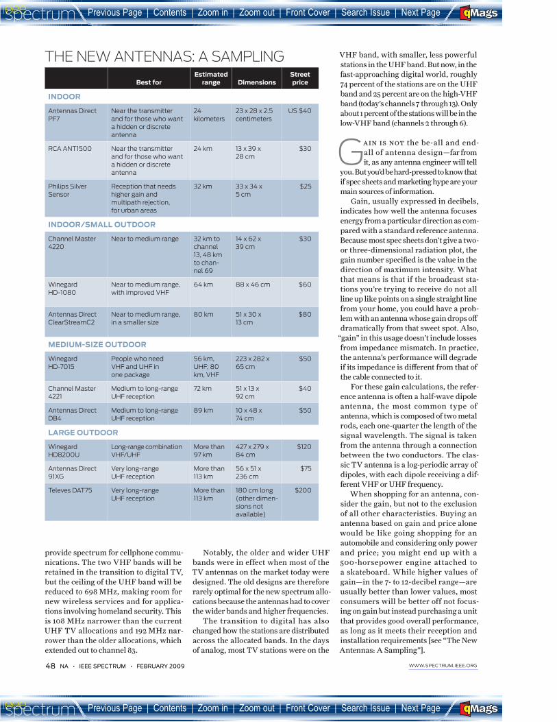
When shopping for an antenna, con-
sider the gain, but not to the exclusion
of all other characteristics. Buying an
antenna based on gain and price alone
would be like going shopping for an
automobile and considering only power
and price; you might end up with a
500- horsepower engine attached to
a skateboard. While higher values of
gain—in the 7- to 12- decibel range—are
usually better than lower values, most
consumers will be better off not focus-
ing on gain but instead purchasing a unit
that provides good overall performance,
as long as it meets their reception and
installation requirements [see “The New
Antennas: A Sampling”].
THE NEW ANTENNAS: A SAMPLING
Best for
Estimated
range Dimensions
Street
price
INDOOR
Antennas Direct
PF7
Near the transmitter
and for those who want
a hidden or discrete
antenna
24
kilometers
23 x 28 x 2.5
centimeters
US $40
RCA ANT1500 Near the transmitter
and for those who want
a hidden or discrete
antenna
24 km 13 x 39 x
28 cm
$30
Philips Silver
Sensor
Reception that needs
higher gain and
multipath rejection,
for urban areas
32 km 33 x 34 x
5 cm
$25
INDOOR/SMALL OUTDOOR
Channel Master
4220
Near to medium range 32 km to
channel
13, 48 km
to chan-
nel 69
14 x 62 x
39 cm
$30
Winegard
HD-1080
Near to medium range,
with improved VHF
64 km 88 x 46 cm $60
Antennas Direct
ClearStreamC2
Near to medium range,
in a smaller size
80 km 51 x 30 x
13 cm
$80
MEDIUM-SIZE OUTDOOR
Winegard
HD-7015
People who need
VHF and UHF in
one package
56 km,
UHF; 80
km, VHF
223 x 282 x
65 cm
$50
Channel Master
4221
Medium to long-range
UHF reception
72 km 51 x 13 x
92 cm
$40
Antennas Direct
DB4
Medium to long-range
UHF reception
89 km 10 x 48 x
74 cm
$50
LARGE OUTDOOR
Winegard
HD8200U
Long-range combination
VHF/UHF
More than
97 km
427 x 279 x
84 cm
$120
Antennas Direct
91XG
Very long-range
UHF reception
More than
113 km
56 x 51 x
236 cm
$75
Televes DAT75 Very long-range
UHF reception
More than
113 km
180 cm long
(other dimen-
sions not
available)
$200
_____________
Previous Page | �ontents | Zoom in | Zoom out | Front �over | Search Issue | Next Page�� B
�
M Sa�EF
Previous Page | �ontents | Zoom in | Zoom out | Front �over | Search Issue | Next Page�� B
�
M Sa�EF
FEBRUARY 2009 • IEEE SPECTRUM • NA 49 WWW.SPECTRUM.IEEE.ORG FEBRUARY 2009 • IEEE SPECTRUM • NA 49 WWW.SPECTRUM.IEEE.ORG
A family in rural Nebraska, for
instance, might need a large, highly direc-
tional antenna, a tower of about 18 meters
(60 feet), and a preamplifier to pick up
stations, which would more than likely
be located somewhere over the horizon.
But that would be complete overkill for
somebody living in Salt Lake City, where
all the broadcast towers are on a moun-
tain ridge just above the city with a line-
of-sight path between most viewers and
the tower. Anywhere near Salt Lake City
you’ll get great reception even with a small
indoor UHF antenna.
Don’t be fooled by claims of
astoundingly high gain. Some
manufacturers are market-
ing small indoor antennas and
labeling the boxes with gain
numbers between 30 and 55 dB.
This kind of unit is actually an
antenna paired with an ampli-
fi er, and the gain value stated on
the package is really the gain of
the amplifi er and not that of the
antenna. While it is possible to
improve reception by using a well-
designed low-noise amplifier,
most of the inexpensive antennas
designed this way actually have
cheap amplifiers and too much
gain. That combination gener-
ally overloads the amplifi er—and
potentially the receiver as well—
causing signal distortion that can
degrade or eliminate DTV recep-
tion entirely. Most consumers are
better o9 with a well-designed nonampli-
fi ed unit, also known as a passive antenna.
If television reception does require an
amplifi er, the best choice is a high-qual-
ity, low-noise model connected as close as
possible to the antenna.
Consumers switching to digital
TV using just an indoor antenna
for reception face a more diJ cult
problem. What was good enough to pro-
vide a watchable, if slightly snowy, ana-
log broadcast is likely to bring nothing
but a blank screen in the digital world.
Even the better antennas must sometimes
be re adjusted to receive certain channels,
forcing viewers out of their easy chairs to
fi ddle with their antennas.
But couch potatoes might soon be able
to stay planted, thanks to a new standard
approved by the Consumer Electronics
Association (CEA) in 2008. The ANSI/
CEA-909A Antenna Control Interface
standard allows the television receiver
to communicate with the antenna,
instructing it to adjust and automati-
cally lock onto the signal as the viewer
channel surfs. Because the antenna and
the receiver both “know” what channel
the user is watching, the antenna can
change either physically or electrically to
adjust tuning, direction, amplifi er gain,
or polarization. The ability to adjust
antenna tuning for each channel allows
engineers to use a narrowband antenna
element to cover a wide range of frequen-
cies. This strate0 is often referred to as
tunable bandwidth. A simple example of
tunable bandwidth is to use a switch to
connect two short rods into a larger rod,
thus reducing the resonant frequency.
Tunable bandwidth relaxes many of the
design compromises, so manufacturers
can produce smaller, higher-performance
antennas. This is particularly important
for indoor antennas, where compactness
and aesthetics are key to adoption.
Not only will ANSI/CEA-909A elim-
inate having to fool with the antenna all
the time, it should make it easier for engi-
neers to design the high-performance,
aesthetically pleasing small antennas
that everyone wants. Audiovox Corp.,
of Hauppauge, N.Y.; Broadcom Corp., of
Irvine, Calif.; and Funai Electric Co., of
Daito, Japan, have demonstrated 909A-
compliant smart antennas, but these
designs have yet to be widely distributed
because hardly any TV receivers on the
market are compatible with them.
That might soon change. The National
Association of Broadcasters (NAB)—the
trade association that represents broad-
cast TV stations—and others are doing
their best to stimulate a market for 909A-
enabled antennas and receivers by pro-
moting the new smart antennas. The NAB
is particularly interested in the 909A tech-
nolo0 because diJ culty in adjusting the
antenna was one of the factors that drove
millions of consumers to cable or satellite
in years past. In 2008, the NAB funded
Antennas Direct, the company that one of
us (Schneider) founded, to develop 909A-
compliant smart antennas because with-
out such a device on the market, television
manufacturers would have no compelling
reason to add the required interface cir-
cuitry to television tuners.
To help encourage manufacturers
to do so, the July 2007 draft of the 909A
standard made a change in the original
specifi cation. In the original design, the
signals to the antenna went over a dedi-
cated cable—that meant another jack in
the back of TVs and another cable for
consumers already struggling with a
tangle of wires. The revised standard
allows signals to be sent over the same
coaxial cable that transmits the televi-
sion signal. The single-cable solution
should spur television manufacturers
to adopt the standard, many being reluc-
tant to include additional connection
ports on the already crowded rear panel
of a modern flat-panel TV. It will also
simplify the connections for technolo0 -
challenged consumers.
With more free content, superior pic-
ture quality, and viable indoor antenna
options coming soon, the broadcasters
may fi nally be in a position to—dare we
say it?—start stealing viewers back from
cable and satellite.
And perhaps strangest of all, an
antenna on the rooftop or perched in
the living room may once again become a
status symbol, as it was in the early days
of television. It won’t be showing o9 that
you’re rich enough to have a TV—just
smart enough to get the most out of it. �
TO PROBE FURTHER
The CEA and NAB provide a Web site (http://
www.antennaweb.org) to help consumers
learn about the transition to digital televi-
sion. The Web site has tools that indicate
what channels are available in specifi c loca-
tions and how to select an antenna to receive
them. Antennas Direct hosts a similar site
(http://www. antennapoint.com), which also
maps transmitter locations and gives dis-
tances and bearings relative to any specifi ed
location in the United States. Both sites o- er
advice on particular antennas and how to
install them for best results.
ClearStream2
_____________
___
__________________
Previous Page | �ontents | Zoom in | Zoom out | Front �over | Search Issue | Next Page�� B
�
M Sa�EF
Previous Page | �ontents | Zoom in | Zoom out | Front �over | Search Issue | Next Page�� B
�
M Sa�EF