technical guidance document
TRANSCRIPT
Conservation of Fuel
and Energy - Buildings
other than Dwellings
Te c h n i c a lG u i d a n c eD o c u m e n t
L
BuildingRegulations
2008
Building Regulations 2008
Techn i ca l G u ida nce D ocument L
Conservation of Fuel and Energy - Bu i l d i n g so ther than Dwe l l i n g s
BAILE ÁTHA CLIATHARNA FHOILSIÚ AG OIFIG AN TSOLÁTHAIRLE CEANNACH dIREACH ONOIFIG dHÍOLTA FOILSEACHÁN RIALTAIS,TEACH SUN ALLIANCE, SRÁId THEACH LAIGHEAN, BAILE ÁTHA CLIATH 2,NO TRId AN BPOST OFOILSEACHÁIN RIALTAIS, AN RANNÓG POST-TRÁCHTA, AONAd 20 PÁIRC MIONdÍOLA COIS LOCHA, CLÁR CHLAINNE MHUIRIS,CONTAE MHAIGH EO(TEIL: 01-6476834/37 NO 1890 213434; FAx: 01-6476843 NO 094-9378964 )NO TRI AON dIOLTOIR LEABHAR.
________________________
dUBLINPUBLISHEd BY THE STATIONERY OFFICETO BE PURCHASEd dIRECTLY FROM THEGOVERNMENT PUBLICATIONS SALE OFFICESUN ALLIANCE HOUSE, MOLESWORTH STREET, dUBLIN 2,OR BY MAIL ORdER FROMGOVERNMENT PUBLICATIONS, POSTAL TRAdE SECTION,UNIT 20 LAKESIdE RETAIL PARK, CLAREMORRIS, CO. MAYO(TEL: 01-6476834/37 OR 1890 213434; FAx: 01-6476843 OR 094 9378964)OR THROUGH ANY BOOKSELLER.
_______________________
€12
Printed on recycled paper containing aminimum of 75% post-consumer waste
Contents
1
Page
Introduction 5
Transitional Arrangements 5The Guidance 5Existing Buildings 5Technical Specifications 5Materials and Workmanship 6Interpretation 6
Building Regulations - The Requirement 7
Section 0: General Guidance
0.1 Application of the Regulations 9
0.2 Technical Risks and Precautions 110.2.1 General 110.2.2 Fire Safety 110.2.3 Ventilation 11
0.3 Thermal Conductivity and Thermal Transmittance 11
0.4 Dimensions 12
0.5 Definitions 12
0.6 Application to Buildings of Architectural or Historical Interest 13
Section 1: Buildings other than Dwellings
1.1 Limitation of Primary Energy Use and C02 emissions for New Buildings other than Dwellings 15
1.2 Heat Loss and Gain through the Building Fabric 161.2.1 Heat Loss - General 161.2.2 Overall Heat Loss Method 161.2.3 Elemental Heat Loss Method 171.2.4 Thermal Bridging 181.2.5 Air Infiltration 211.2.6 Avoiding Solar Overheating 21
1.3 Building Services 231.3.1 Heating Plant Efficiency 231.3.2 Controls for Space Heating and Hot Water Supply
Systems 231.3.3 Air Conditioning and Mechanical Ventilation (ACMV) 231.3.4 Insulation of Storage Vessels, Pipes and Ducts 241.3.5 Artificial Lighting 24
42
Appendices
A Calculation of U-values 27B Fabric Insulation: Additional Guidance (including Tables of U-Values)
for Common Constructions 35C Reference Values for Calculation of Maximum Permitted Energy
Performance Coefficient (MPEPC) and Maximum Permitted CarbonPerformance Coefficient (MPCPC) 57
D Thermal Bridging 60E Avoidance of Solar Overheating 62
STAnDARDS AnD OThER REFEREnCES 65
5
IntroductionThis document has been published by the Minister for theEnvironment, Heritage and Local Government underarticle 7 of the Building Regulations 1997.
It provides guidance in relation to Part L of the SecondSchedule to the Regulations as inserted by BuildingRegulations (Part L Amendment) Regulations 2008 (S.I.No. 259 of 2008). The guidance in this document appliesto buildings other than dwellings.
These Regulations (and this document) partly transposethe EU Energy Performance of Buildings
Directive - EPBD (2002/91/EC of 16 December
2002).
The document should be read in conjunction with theBuilding Regulations 1997-2005 and other documentspublished under these Regulations.
In general, Building Regulations apply to the constructionof new buildings and to extensions and materialalterations to existing buildings. In addition, certain partsof the Regulations apply to existing buildings where amaterial change of use takes place. (Otherwise, BuildingRegulations do not apply to buildings constructed prior to1 June 1992).
Transitional ArrangementsIn general, this document applies to works, or buildings inwhich a material alteration or change of use takes place,where the work, material alteration or the change of usecommences or takes place, as the case may be, on orafter 10 July 2008.
Technical Guidance Document L - Conservation of Fueland Energy (May 2006 edition) ceases to have effect from9 July 2008.
However, this document may continue to be used in thecase of buildings:
- where the work, material alteration or the change ofuse commences or takes place, as the case may be, onor before 30 June 2008, or
- where planning approval or permission has beenapplied for on or before 30 June 2008, and substantialwork has been completed by 30 June 2010.
“Substantial work has been completed” means that thestructure of the external walls has been erected.
The GuidanceThe materials, methods of construction, standards andother specifications (including technical specifications)
which are referred to in this document are those whichare likely to be suitable for the purposes of the BuildingRegulations (as amended). Where works are carried outin accordance with the guidance in this document, thiswill, prima facie, indicate compliance with Part L of theSecond Schedule to the Building Regulations.
However, the adoption of an approach other than thatoutlined in the guidance is not precluded provided thatthe relevant requirements of the Regulations are compliedwith. Those involved in the design and construction of abuilding may be required by the relevant building controlauthority to provide such evidence as is necessary toestablish that the requirements of the Regulations arebeing complied with.
Existing BuildingsIn the case of material alterations or change of use ofexisting buildings, the adoption without modification ofthe guidance in this document may not, in allcircumstances, be appropriate. In particular, theadherence to guidance, including codes, standards ortechnical specifications intended for application to newwork may be unduly restrictive or impracticable.
Buildings of architectural or historical interest areespecially likely to give rise to such circumstances. Inthese situations, alternative approaches based on theprinciples contained in the document may be morerelevant and should be considered.
Technical SpecificationsBuilding Regulations are made for specific purposes, e.g.to provide, in relation to buildings, for the health, safetyand welfare of persons, the conservation of energy, andaccess for people with disabilities.
Technical specifications (including harmonised EuropeanStandards, European Technical Approvals, NationalStandards and Agrement Certificates) are relevant to theextent that they relate to these considerations.
Any reference to a technical specification is a reference toso much of the specification as is relevant in the contextin which it arises. Technical specification may also addressother aspects not covered by the Regulations.
A reference to a technical specification is to the latestedition (including any amendments, supplements oraddenda) current at the date of publication of thisTechnical Guidance Document. However, if this versionof the technical specification is subsequently revised orupdated by the issuing body, the new version may be usedas a source of guidance provided that it continues toaddress the relevant requirements of the Regulations.
Building Regulations 2008 Technical Guidance Document LConservation of Fuel and Energy - Buildings other than Dwellings
6
Materials and WorkmanshipUnder Part D of the Second Schedule to the BuildingRegulations, building work to which the Regulations applymust be carried out with proper materials and in aworkmanlike manner. Guidance in relation to compliancewith Part D is contained in Technical GuidanceDocument D.
Interpretation
In this document, a reference to a section, paragraph,appendix or diagram is, unless otherwise stated, areference to a section, paragraph, appendix or diagram, asthe case may be, of this document. A reference toanother Technical Guidance Document is a reference tothe latest edition of a document published by theDepartment of the Environment, Heritage and LocalGovernment under article 7 of the Building Regulations1997.
Diagrams are used in this document to illustrate particularaspects of construction - they may not show all the detailsof construction.
7
Conservation of Fuel and Energy
Building Regulations - The Requirement
The requirements regarding conservation of fuel and energy are laid out in Part L of the Second Schedule to theBuilding Regulations 1997 (S.I. No. 497 of 1997) as amended by the Building Regulations (Part L Amendment)Regulations 2008 (S.I. No. 259 of 2008).
The Second Schedule is amended to read, in relation to buildings other than dwellings, as follows:
Conservation of Fuel L1 A building shall be designed and constructed so as to ensure that the energy
and Energy performance of the building is such as to limit the amount of energy required
for the operation of the building and the amount of CO2 emissions associated
with this energy use insofar as is reasonably practicable.
Buildings other L4 For buildings other than dwellings, the requirements of L1 shall be met by:
than dwellings
(a) providing that the energy performance of the new building is such as to
limit the calculated primary energy consumption and related CO2
emissions insofar as is reasonably practicable, when both energy
consumption and CO2 emissions are calculated using the Non-domestic
Energy Assessment Procedure (NEAP) published by Sustainable Energy
Ireland;
(b) limiting the heat loss and, where appropriate, maximising the heat gains
through the fabric of the building;
(c) providing energy efficient space and water heating services including
adequate control of these services;
(d) ensuring that the building is appropriately designed to limit need for
cooling and, where air-conditioning or mechanical ventilation is installed,
that installed systems are energy efficient, appropriately sized and
adequately controlled;
(e) limiting the heat loss from pipes, ducts and vessels used for the transport
or storage of heated water or air;
(f) limiting the heat gains by chilled water and refrigerant vessels, and by
pipes and ducts that serve air conditioning systems;
(g) providing energy efficient artificial lighting systems (other than emergency
lighting, display lighting or specialist process lighting) and adequate control
of these systems.
8
Section 0:
General Guidance

9
-0.1 APPLICATIOn OF ThEREGULATIOnS
0.1.1 The aim of Part L of the First Schedule tothe Building Regulations is to limit the use of fossilfuel energy and related CO2 emissions arising fromthe operation of buildings, while ensuring thatoccupants can achieve adequate levels of lighting andthermal comfort. Buildings should be designed andconstructed to achieve this aim as far as ispracticable.
0.1.2 For new buildings other than dwellings, thekey issues to be addressed in order to ensurecompliance are:
a. to provide that the calculated primary energyconsumption associated with the operation ofthe building and the related CO2 emissions asdescribed in Section 1.1 do not exceed atarget value specified in this document;
b. to limit the heat loss and, where appropriate,maximise the heat gains through the fabric ofthe building;
c. to provide energy efficient space and waterheating services including adequate control ofthese services;
d. to ensure that the building is appropriatelydesigned to limit the need for cooling and,where air-conditioning or mechanicalventilation is installed, that installed systemsare energy efficient, appropriately sized andadequately controlled;
e. to limit the heat loss from pipes, ducts andvessels used for the transport or storage ofheated water or air;
f. to limit the heat gains by chilled water andrefrigerant vessels, and by pipes and ducts thatserve air conditioning systems;
g. to provide energy efficient artificial lightingsystems (other than emergency lighting, displaylighting or specialist process lighting) andadequate control of these systems.
The principal aims of Part L of the BuildingRegulations are to limit primary energy consumptionand associated CO2 emissions. Meeting theperformance levels specified for items b to g will notnecessarily mean that the level specified for primaryenergy consumption and related CO2 emissions(item a) will be met. It is likely that one or more ofthe performance levels specified, for items b to g, willneed to be exceeded to achieve this.
0.1.3 Where a dwelling has an attached room orspace that is to be used for commercial purposes(e.g. workshop, surgery, consulting room or office),such room or space should be treated as part of thedwelling if the commercial part could revert todomestic use on a change of ownership, e.g. wherethere is direct access between the commercial spaceand the living accommodation, both are containedwithin the same thermal envelope and the livingaccommodation occupies a substantial proportion ofthe total area of the building.
0.1.4 The guidance given in this TechnicalGuidance Document is generally applicable. However,where the works are limited in nature and not likelyto greatly affect overall energy consumption over thebuilding’s life, compliance may be achieved withoutimplementation of this guidance or equivalentmeasures in detail. In particular,
- For small extensions, not exceeding 6.5m2 infloor area, reasonable provision can beconsidered to have been made if the newconstruction is similar to the existingconstruction.
- Unheated ancillary areas such as porches,garages and the like do not require specificprovisions in order to satisfy this Part of theBuilding Regulations.
- Where the area treated by an AirConditioning and Mechanical Ventilation(ACMV) system is less than 200 m2, theguidance in relation to ACMV systems neednot be applied.
- Where the total design lighting load does notexceed 1000 W, the guidance in relation to theefficiency and control of artificial lighting neednot be applied.
10
0.1.5 The guidance given in this TechnicalGuidance Document applies to buildings designed tobe heated to temperatures appropriate for humanoccupancy. Less demanding standards couldrepresent reasonable provision in those buildings orparts of buildings with a low level of heating orwhere heating provision is not intended. Low level ofheating is considered to be where there is aninstalled heating capacity of less than 10W/m2.
Where the occupancy level or level of heatingrequired when in use cannot be established atconstruction stage, the building should be treated asfully heated and the provisions of Part L appliedaccordingly. It should be noted that the provisions ofPart L apply where a material change of use occursand such a change of use may require specificconstruction measures to comply with Part L. Thesemeasures may prove more costly than if carried outat the time of initial construction.
0.1.6 An attached conservatory-style sunspace orthe like should generally be treated as an integralpart of the building to which it is attached. However,where
- thermally separated from the adjacent spaceswithin the building by walls, doors and otheropaque elements which have U-values notmore than 10% greater than correspondingexposed elements, and
- unheated or, if providing with a heating facility,having provision for automatic temperatureand on-off control independent of the heatingprovision in the main building,
it may be excluded from the assessment of thebuilding for the purposes of asessing compliance withthe provisions of Part L. In this case, the building maybe assessed separately for compliance. The attachedsunspace should be treated as an unheated space forthe purposes of this assessment and should also beassessed separately as if it were an extension to anexisting building (see Paragraph 1.2.3.3 below).
0.1.7 In large complex buildings it may be sensibleto consider the provisions for conservation of fueland energy separately for different parts of the
building in order to establish the measuresappropriate to each part.
0.1.8 The Regulations apply to all works to existingbuildings that are covered by the requirements of theBuilding Regulations, including extensions, materialalterations, material changes of use and window anddoor replacement. In carrying out this work, the aimshould be to limit energy requirements for theoperation of the building and associated CO2
emissions as far as practicable as required byRegulation L1.
The key issues to be addressed are:
(a) limiting the heat loss and, where appropriate,maximising the heat gains through the fabric ofthe building;
(b) providing energy efficient space and waterheating services including adequate control ofthese services;
(c) ensuring that the building is appropriatelydesigned to limit need for cooling and, whereair-conditioning or mechanical ventilation isinstalled, that installed systems are energyefficient, appropriately sized and adequatelycontrolled;
(d) limiting the heat loss from pipes, ducts andvessels used for the transport or storage ofheated water or air;
(e) limiting the heat gains by chilled water andrefrigerant vessels, and by pipes and ducts thatserve air conditioning systems;
(f) providing energy efficient artificial lightingsystems (other than emergency lighting, displaylighting or specialist process lighting) andadequate control of these systems.
11
0.2 TEChnICAL RISkS AnD
PRECAUTIOnSGeneral
0.2.1 The incorporation of additional thickness ofthermal insulation and other energy conservationmeasures can result in changes in traditionalconstruction practice. Care should be taken in designand construction to ensure that these changes donot increase the risk of certain types of problems,such as rain penetration and condensation.
Some guidance on avoiding such increased risk isgiven in Appendix B of this document. Generalguidance on avoiding risks that may arise is alsocontained in the publication “Thermal insulation:
avoiding risks; Building Research Establishment (Ref BR262)”.
Guidance in relation to particular issues andmethods of construction will be found in relevantstandards.
Fire Safety
0.2.2 Part B of the Second Schedule to the BuildingRegulations prescribes fire safety requirements. Indesigning and constructing buildings to comply withPart L, these requirements must be met and theguidance in relation to fire safety in TGD B should befully taken into account. In particular, it is importantto ensure that windows, which provide secondarymeans of escape in accordance with Section 1.5 ofTGD B, comply with the dimensional and otherguidance for such windows set out in paragraph 1.5.6of TGD B.
Ventilation
0.2.3 Part F of the Second Schedule to the BuildingRegulations prescribes ventilation requirements bothto meet the needs of the occupants of the buildingand to prevent excessive condensation in roofs androofspaces. A key aim of the provisions in relation tothe ventilation of occupied spaces is to minimize therisk of condensation, mould growth or other indoorair quality problems. Technical Guidance Document Fprovides guidance in relation to ventilation ofbuildings.
Part J of the Second Schedule to the BuildingRegulations prescribes requirements in relation tothe supply of air for combustion appliances, includingopen-flued appliances which draw air from the roomor space in which they are situated. TechnicalGuidance Document J provides guidance in thisregard.
0.3 ThERMAL COnDUCTIVITy AnDThERMAL TRAnSMITTAnCE
0.3.1 Thermal conductivity (λ-value) relates to amaterial or substance, and is a measure of the rate atwhich heat passes through a uniform slab of unitthickness of that material or substance, when unittemperature difference is maintained between itsfaces. It is expressed in units of Watts per metre perdegree (W/mK).
0.3.2 For the purpose of showing compliance withthis Part of the Building Regulations, design λ-valuesbased on manufacturers declared values should beused. For thermally homogeneous materials declaredand design values should be determined inaccordance with I.S. EN ISO 10456: 1997. Designvalues for masonry materials should be determinedin accordance with I.S. EN 1745: 2002. For insulationmaterials, values determined in accordance with theappropriate harmonized European standard shouldbe used. Certified λ-values for foamed insulantmaterials should take account of the blowing agentactually used. The use of HCFC for this purpose isno longer permitted.
For products or components for which noappropriate standard exists, measured values,certified by an approved body or certified laboratory(see TGD D), should be used.
0.3.3 Table A1 and A2 of Appendix A contains λ-values for some common building materials andinsulation materials. These are primarily based ondata contained in I.S. EN 12524: 2000 or in CIBSEGuide A, Section A3. The values provide a generalindication of the thermal conductivity that may beexpected for these materials. In the absence ofdeclared values, design values or certified measuredvalues as outlined in paragraph 0.3.2, values ofthermal conductivity given in Table A1 may be used.However, values for specific products may differ fromthese illustrative values. Indicative λ-values for
12
thermal insulation materials are given Table A2.These may be used at early design stage for thepurpose of assessing likely compliance with this Partof the Regulations. However, compliance should beverified using thermal conductivity values for thesematerials derived as outlined in Paragraph 0.3.2above.
0.3.4 Thermal transmittance (U-value) relates to abuilding component or structure, and is a measure ofthe rate at which heat passes through thatcomponent or structure when unit temperaturedifference is maintained between the ambient airtemperatures on each side. It is expressed in units ofWatts per square metre per degree of airtemperature difference (W/m2K).
0.3.5 Thermal transmittance values (U-values)relevant to this Part of the Regulations are thoserelating to elements exposed directly or indirectly tothe outside air. This includes floors directly in contactwith the ground, suspended ground floorsincorporating ventilated or unventilated voids, andelements exposed indirectly via unheated spaces. TheU-value takes account of the effect of the ground,voids and unheated spaces on the rate of heat loss,where appropriate. Heat loss through elements thatseparate premises that can reasonably be assumed tobe heated, is considered to be negligible. Suchelements do not need to meet any particular U-valuenor should they be taken into account in calculationof CO2 emissions or overall transmission heat loss.
0.3.6 A range of methods exists for calculating U-values of building elements. Methods of calculationare outlined in Appendix A, together with examplesof their use. Alternatively U-values may be based oncertified measured values. Measurements of thermaltransmission properties of building componentsgenerally should be made in accordance with I.S. ENISO 8990: 1997, or, in the case of windows anddoors, I.S. EN ISO 12567-1: 2001.
0.3.7 Any part of a roof that has a pitch of 700 ormore may be treated as a wall for the purpose ofassessing the appropriate level of thermaltransmission. Elements separating the building fromspaces that can reasonably be assumed to be heatedshould not be included .
0.3.8 Appendix B contains tables of indicative U-values for certain common constructions. These arederived using the calculation methods referred to inAppendix A, and may be used in place of calculatedor measured values, where appropriate. These tablesprovide a simple way to establish the U-value for agiven amount of insulation. Alternatively they may beused to establish the amount of insulation needed toachieve a given U-value. The values in the tables havebeen derived taking account of typical repeatedthermal bridging where appropriate. Where anelement incorporates a non-repeating thermalbridge, e.g. where the continuity of insulation isbroken or penetrated by material of reducedinsulating quality, the U-value derived from the tableshould be adjusted to account for this thermalbridge. Table B24 in Appendix B contains indicativeU-values for external doors, windows and rooflights(roof windows).
0.4 DIMEnSIOnS
0.4.1 Except where otherwise indicated linearmeasurements for the calculation of wall, roof andfloor areas and building volumes should be takenbetween the finished internal faces of theappropriate external building elements and, in thecase of roofs, in the plane of the insulation. Linearmeasurements for the calculation of the areas ofexternal door, window and rooflight openings shouldbe taken between internal faces of appropriate cills,lintels and reveals.
0.4.2 “Volume" means the total volume enclosedby all enclosing elements and includes the volume ofnon-usable spaces such as ducts, stairwells and floorvoids in intermediate floors.
0.5 DEFInITIOnS
0.5.1 For the purposes of this Technical GuidanceDocument the following definitions apply:
Energy Use (for a particular purpose e.g. spaceheating, water heating, repeat cooling, ventilation,lighting): Energy input to the relevant system tosatisfy the relevant purpose.
Delivered Energy: Energy supplied to the building andits systems to satisfy the relevant energy uses e.g.
13
space heating, water heating, cooling, ventilation,lighting. Delivered energy does not include renewableenergy produced on site.
Delivered energy differs from energy use by theextent of on-site conversion and transformationlosses e.g. boiler efficiency losses.
Primary Energy: Energy that has not been subjected toany conversion or transformation process. For abuilding, it is the delivered energy plus the energyused to produce the energy delivered to the building.It is calculated from the delivered energy, with anallowance for any energy exported from the site,using conversion factors.
Renewable Energy: Energy from renewable non-fossilenergy sources e.g. solar energy (thermal andphotovoltaic), wind, hydropower, biomass,geothermal, wave, tidal, landfill gas, sewage treatmentplant gas and biogases.
Biomass: Biodegradable fraction of products, wasteand residues from agriculture (including vegetal andanimal substances), forestry and related industries, aswell as biodegradable fraction of industrial andmunicipal waste, used as a fuel or energy source.Fuels derived from biomass may be in solid, liquid orgas form. In this document, where the term“biomass” is used on it’s own, it should be taken tomean solid biomass (wood, wood chip, wood pellet,etc).
Biofuel: Liquid or gas fuel derived from biomass.
Note: Biomass (including biofuel) is generally includedin Delivered Energy and thus, together with theenergy used to produce and deliver it, included inPrimary Energy.
0.6 APPLICATIOn TO BUILDInGS OFARChITECTURAL OR hISTORICALInTEREST
0.6.1 Part L does not apply to works (includingextensions) to an existing building which is a“protected structure” or a ‘proposed protectedstructure” within the meaning of the Planning andDevelopment Act 2000 (No 30 of 2000).
Nevertheless, the application of this Part may poseparticular difficulties for buildings which, although notprotected structures or proposed protectedstructures may be of architectural or historicalinterest.
Works such as the replacement of doors, windowsand rooflights, the provision of insulated dry liningand damp-proofing to walls and basements, insulationto the underside of slating and provision of roofvents and ducting of pipework could all affect thecharacter of the structure.
In general, the type of works described above shouldbe carefully assessed for their material and visualimpact on the structure.
Historic windows and doors should be repairedrather than replaced, and drylining and damp-proofing should not disrupt or damage historicplasterwork or flagstones and should not introducefurther moisture into the structure.
Roof insulation should be achieved without damageto slating (either during the works or from erosiondue to condensation) and obtrusive vents should notaffect the character of the roof.
In specific cases, relaxation of the values proposedmay be acceptable, to the local building controlauthority, if it can be shown to be necessary in orderto preserve the architectural integrity of theparticular building.
For more guidance on appropriate measures see“Planning Guidelines No. 9: Architectural Heritage
Protection - Guidelines for Planning Authorities”published by the Department of the Environment,Heritage and Local Government.
Section 1: Buildings other than
Dwellings
14
15
1.1: Limitation of Primary Energy Use and CO2emissions for New Buildings other than Dwellings
1.1.1 This Section provides guidance on how toshow compliance with the requirements in relationto primary energy consumption and CO2 emissionsspecified in Regulation L4(a). The framework forcalculation to be used is specified in the Regulationas the Non domestic Energy Assessment Procedure(NEAP). This framework enables the use of either asimplified building energy method or an approvedalternative method. This framework is published bySustainable Energy Ireland (SEI) and calculates theenergy consumption and CO2 emissions associatedwith a standardised use of a building. The energyconsumption is expressed in terms of kilowatt hoursper square metre floor area per year (kWh/m2/yr)and the CO2 emissions expressed in terms ofkilograms of CO2 per square metre floor area peryear (kg CO2/m2/yr). Full details of the frameworkare available on the SEI website at http://www.sei.ie.
1.1.2 The performance criteria are based on therelative values of the calculated primary energyconsumption and CO2 emissions of a building beingassessed, and similar calculated values for aReference Building. Details of the Reference Buildingare given in Appendix C. The criteria are determinedas follows:
- Primary energy consumption and CO2
emissions for both the proposed building andthe reference building are calculated usingNEAP.
- The calculated primary energy consumption ofthe proposed building is divided by that of thereference building, the result being the energyperformance coefficient (EPC) of the proposedbuilding. To demonstrate that an acceptablePrimary Energy consumption rate has beenachieved, the calculated EPC of the buildingbeing assessed should be no greater than theMaximum Permitted Energy PerformanceCoefficient (MPEPC). The MPEPC is 1.0.
- The calculated CO2 emission rate of theproposed building is divided by that of thereference building, the result being the carbonperformance coefficient (CPC) of theproposed building. To demonstrate that anacceptable CO2 emission rate has beenachieved, the calculated CPC of the buildingbeing assessed should be no greater than the
Maximum Permitted Carbon PerformanceCoefficient (MPCPC). The MPCPC is 1.0.
Each method within the NEAP framework willcalculate the EPC and CPC of the building beingassessed and clearly indicate whether compliancewith the requirements of Regulation L4(a) has beenachieved.
1.1.3 The requirements that the calculated EPCand CPC do not exceed the MPEPC and MPCPCrespectively, applies to the constructed building.Designers may wish to calculate the EPC and CPC atearly design stage in order to ensure that therequirements can be achieved by the constructedbuilding. However, the use of constructions andservice systems which have been assessed at designstage, or other model designs, does not preclude theneed to verify compliance by calculating the EPC andCPC when all relevant details of the finalconstruction are known.
1.1.4 Primary energy does not include energyderived from on-site renewable energy technologies.In addition, as renewable energy technologiesgenerally are characterised by zero, or greatlyreduced, CO2 emissions, the calculated EPC and CPCare reduced by the extent that they replacetraditional fossil fuels.
16
1.2: Heat Loss and Gain through the
Building Fabric
1.2.1 hEAT LOSS - GEnERAL
1.2.1.1 The following two methods may be used todemonstrate that an acceptable level of transmissionheat loss through the elements bounding the heatedbuilding volume is achieved-
(a) The Overall Heat Loss method (paragraph1.2.2). This method is applicable to newbuildings and extensions to existing buildings;or
(b) The Elemental Heat Loss method (paragraph1.2.3). While this method may be used for anybuilding, it is primarily appropriate for smallbuildings, e.g. less than 300 m2 floor area, smallsections of large complex buildings, commonareas of apartment blocks, material alterationsand material changes of use.
For both methods, the guidance regarding thelimitation of thermal bridging and uncontrolled airinfiltration through the building fabric (paragraphs1.2.4 and 1.2.5) and the control of overheating(paragraph 1.2.6) should be followed.
1.2.1.2 The derivation of U-values, including thoseapplicable where heat loss is to an unheated space, isdealt with in Paragraphs 0.3.5 to 0.3.6 and AppendixA.
Unheated areas which are wholly or largely withinthe building structure and are not subject toexcessive air-infiltration or ventilation, e.g. stairwells,corridors in buildings containing flats, may beconsidered as within the insulated fabric. In thatcase, if the external fabric of these areas is insulatedto the same level as that achieved by equivalentadjacent elements, no particular requirement forinsulation between the heated and unheated areaswould arise.
1.2.1.3 The treatment of an attached conservatory-style sunspace is dealt with in Paragraph 0.1.6.Where an attached sunspace is treated as anextension to the main building for the purposes ofassessment for compliance with the provisions ofPart L (as provided for in Paragraph 0.1.6), theguidance in Paragraph 1.2.3.3 should be followed.
1.2.1.4 This Part of the Building Regulations appliesto the replacement of external doors, windows, orrooflights in an existing building. The average U-value of replacement units should not exceed thevalue of 2.2 W/m2K. The limitations on openingareas set out in Table 3 do not apply. In this context,the repair or renewal of parts of individual elements,e.g. window glass, window casement sash, door leafshould be considered as repair and not replacement.
1.2.2 OVERALL hEAT LOSS
METhOD
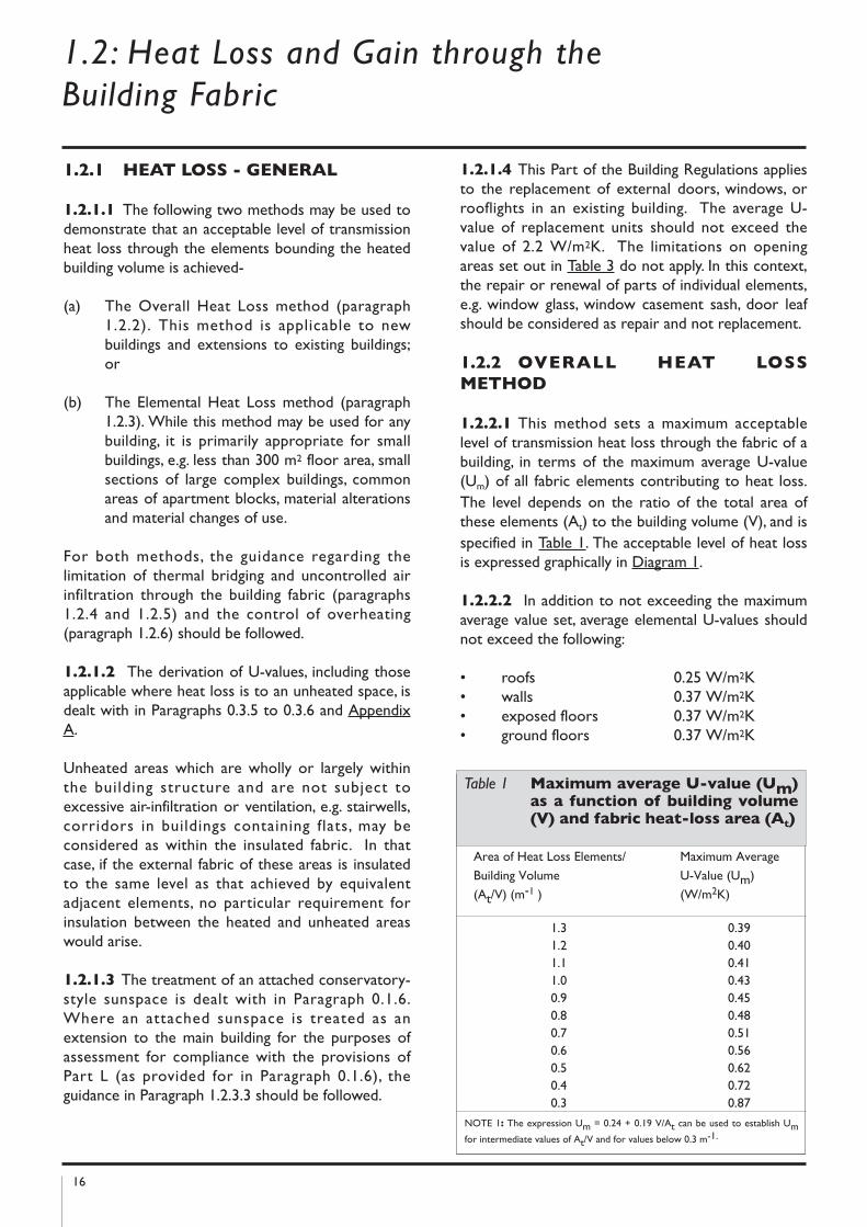
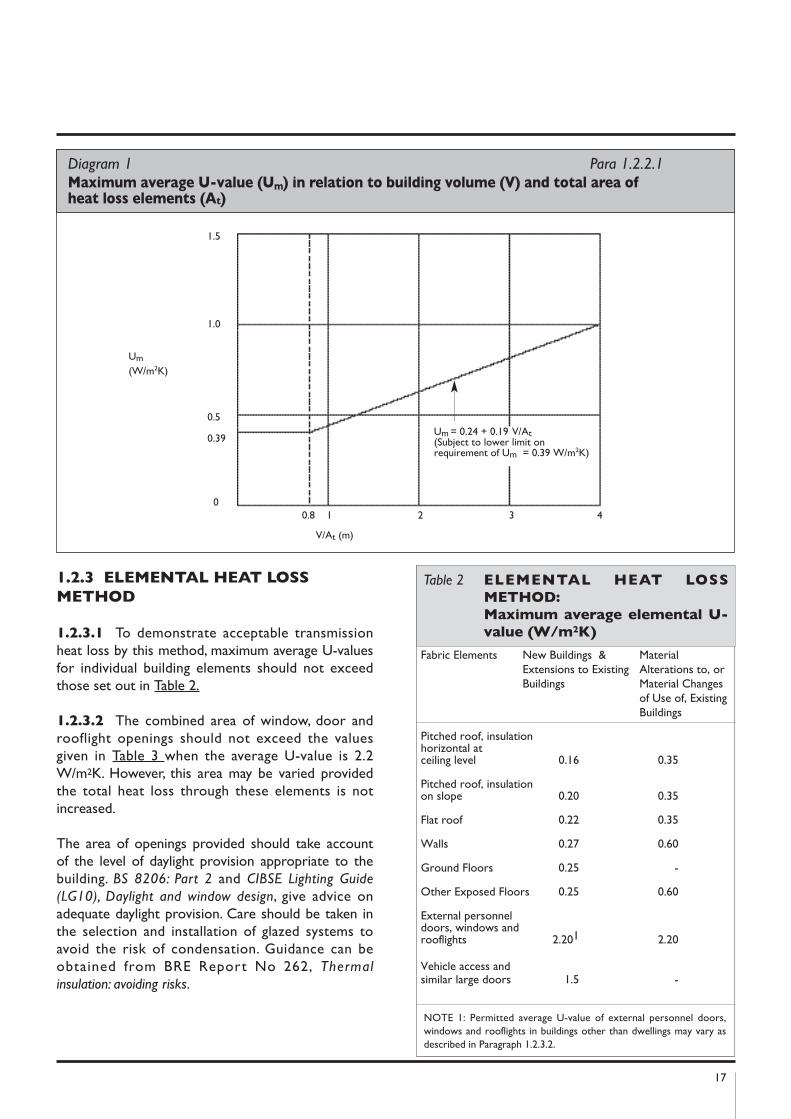
1.2.2.1 This method sets a maximum acceptablelevel of transmission heat loss through the fabric of abuilding, in terms of the maximum average U-value(Um) of all fabric elements contributing to heat loss.The level depends on the ratio of the total area ofthese elements (At) to the building volume (V), and isspecified in Table 1. The acceptable level of heat lossis expressed graphically in Diagram 1.
1.2.2.2 In addition to not exceeding the maximumaverage value set, average elemental U-values shouldnot exceed the following:
• roofs 0.25 W/m2K• walls 0.37 W/m2K• exposed floors 0.37 W/m2K• ground floors 0.37 W/m2K
Area of Heat Loss Elements/ Maximum Average
Building Volume U-Value (Um)
(At/V) (m-1 ) (W/m2K)
1.3 0.391.2 0.401.1 0.411.0 0.430.9 0.450.8 0.480.7 0.510.6 0.560.5 0.620.4 0.720.3 0.87
Table 1 Maximum average U-value (Um)as a function of building volume(V) and fabric heat-loss area (At)
NOTE 1: The expression Um = 0.24 + 0.19 V/At can be used to establish Umfor intermediate values of At/V and for values below 0.3 m-1.
17
1.2.3 ELEMEnTAL hEAT LOSS
METhOD
1.2.3.1 To demonstrate acceptable transmissionheat loss by this method, maximum average U-valuesfor individual building elements should not exceedthose set out in Table 2.
1.2.3.2 The combined area of window, door androoflight openings should not exceed the valuesgiven in Table 3 when the average U-value is 2.2W/m2K. However, this area may be varied providedthe total heat loss through these elements is notincreased.
The area of openings provided should take accountof the level of daylight provision appropriate to thebuilding. BS 8206: Part 2 and CIBSE Lighting Guide
(LG10), Daylight and window design, give advice onadequate daylight provision. Care should be taken inthe selection and installation of glazed systems toavoid the risk of condensation. Guidance can beobtained from BRE Report No 262, Thermal
insulation: avoiding risks.
Diagram 1 Para 1.2.2.1Maximum average U-value (Um) in relation to building volume (V) and total area of heat loss elements (At)
1.5
1.0
0.5
0.39
00.8 1 2 3 4
V/At (m)
Um = 0.24 + 0.19 V/At(Subject to lower limit on requirement of Um = 0.39 W/m2K)
Um
(W/m2K)
Fabric Elements New Buildings & Material Extensions to Existing Alterations to, or Buildings Material Changes
of Use of, Existing Buildings
Pitched roof, insulation horizontal at ceiling level 0.16 0.35
Pitched roof, insulation on slope 0.20 0.35
Flat roof 0.22 0.35
Walls 0.27 0.60
Ground Floors 0.25 -
Other Exposed Floors 0.25 0.60
External personnel doors, windows and rooflights 2.201 2.20
Vehicle access and similar large doors 1.5 -
Table 2 ELEMEnTAL hEAT LOSS
METhOD:
Maximum average elemental U-
value (W/m2k)
NOTE 1: Permitted average U-value of external personnel doors,windows and rooflights in buildings other than dwellings may vary asdescribed in Paragraph 1.2.3.2.
18
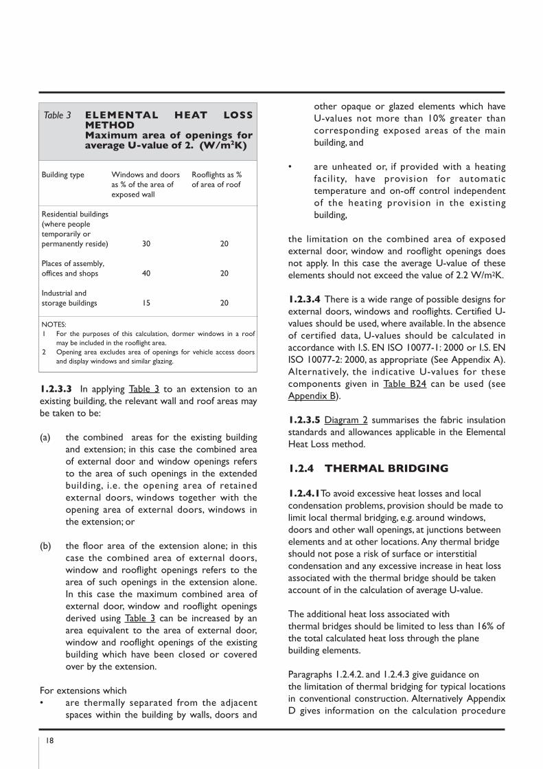
1.2.3.3 In applying Table 3 to an extension to anexisting building, the relevant wall and roof areas maybe taken to be:
(a) the combined areas for the existing buildingand extension; in this case the combined areaof external door and window openings refersto the area of such openings in the extendedbuilding, i.e. the opening area of retainedexternal doors, windows together with theopening area of external doors, windows inthe extension; or
(b) the floor area of the extension alone; in thiscase the combined area of external doors,window and rooflight openings refers to thearea of such openings in the extension alone.In this case the maximum combined area ofexternal door, window and rooflight openingsderived using Table 3 can be increased by anarea equivalent to the area of external door,window and rooflight openings of the existingbuilding which have been closed or coveredover by the extension.
For extensions which • are thermally separated from the adjacent
spaces within the building by walls, doors and
other opaque or glazed elements which haveU-values not more than 10% greater thancorresponding exposed areas of the mainbuilding, and
• are unheated or, if provided with a heatingfacil ity, have provision for automatictemperature and on-off control independentof the heating provision in the existingbuilding,
the limitation on the combined area of exposedexternal door, window and rooflight openings doesnot apply. In this case the average U-value of theseelements should not exceed the value of 2.2 W/m2K.
1.2.3.4 There is a wide range of possible designs forexternal doors, windows and rooflights. Certified U-values should be used, where available. In the absenceof certified data, U-values should be calculated inaccordance with I.S. EN ISO 10077-1: 2000 or I.S. ENISO 10077-2: 2000, as appropriate (See Appendix A).Alternatively, the indicative U-values for thesecomponents given in Table B24 can be used (seeAppendix B).
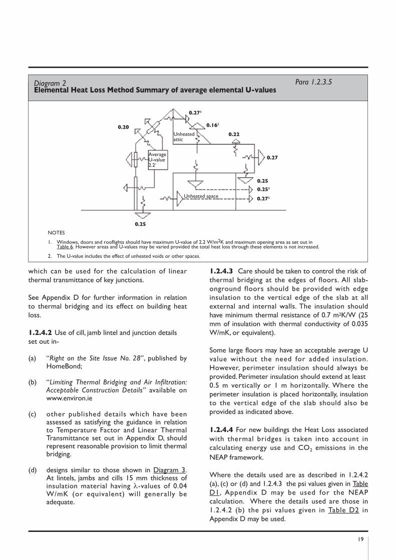
1.2.3.5 Diagram 2 summarises the fabric insulationstandards and allowances applicable in the ElementalHeat Loss method.
1.2.4 ThERMAL BRIDGInG
1.2.4.1To avoid excessive heat losses and localcondensation problems, provision should be made tolimit local thermal bridging, e.g. around windows,doors and other wall openings, at junctions betweenelements and at other locations. Any thermal bridgeshould not pose a risk of surface or interstitialcondensation and any excessive increase in heat lossassociated with the thermal bridge should be takenaccount of in the calculation of average U-value.
The additional heat loss associated withthermal bridges should be limited to less than 16% ofthe total calculated heat loss through the planebuilding elements.
Paragraphs 1.2.4.2. and 1.2.4.3 give guidance onthe limitation of thermal bridging for typical locationsin conventional construction. Alternatively AppendixD gives information on the calculation procedure
Building type Windows and doors Rooflights as %as % of the area of of area of roofexposed wall
Residential buildings (where peopletemporarily or permanently reside) 30 20
Places of assembly, offices and shops 40 20
Industrial and storage buildings 15 20
Table 3 ELEMEnTAL hEAT LOSSMEThODMaximum area of openings foraverage U-value of 2. (W/m2k)
NOTES: 1 For the purposes of this calculation, dormer windows in a roof
may be included in the rooflight area.2 Opening area excludes area of openings for vehicle access doors
and display windows and similar glazing.
19
which can be used for the calculation of linearthermal transmittance of key junctions.
See Appendix D for further information in relationto thermal bridging and its effect on building heatloss.
1.2.4.2 Use of cill, jamb lintel and junction detailsset out in-
(a) “Right on the Site Issue No. 28”, published byHomeBond;
(b) “Limiting Thermal Bridging and Air Infiltration:Acceptable Construction Details” available onwww.environ.ie
(c) other published details which have beenassessed as satisfying the guidance in relationto Temperature Factor and Linear ThermalTransmittance set out in Appendix D, shouldrepresent reasonable provision to limit thermalbridging.
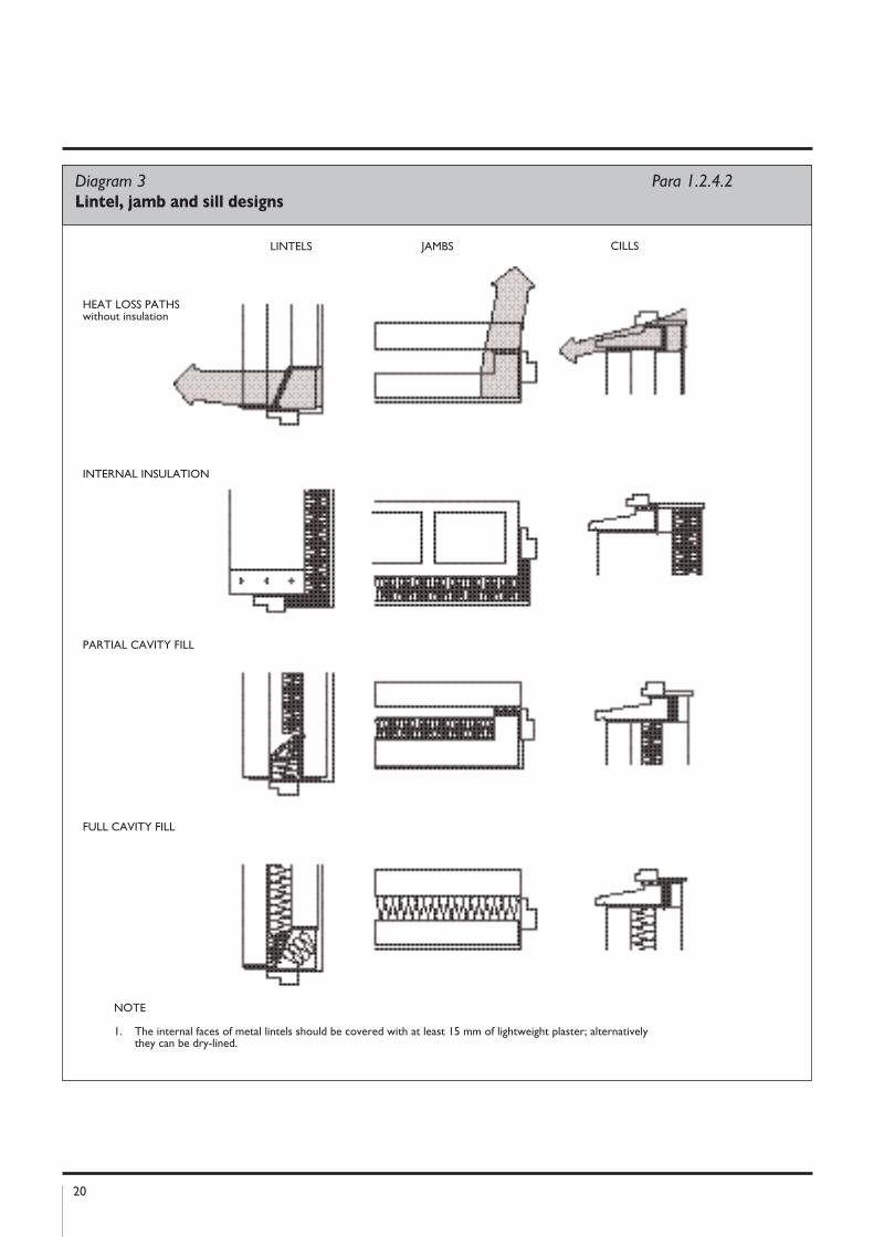
(d) designs similar to those shown in Diagram 3.At lintels, jambs and cills 15 mm thickness ofinsulation material having λ-values of 0.04W/mK (or equivalent) will generally beadequate.
1.2.4.3 Care should be taken to control the risk ofthermal bridging at the edges of floors. All slab-onground floors should be provided with edgeinsulation to the vertical edge of the slab at allexternal and internal walls. The insulation shouldhave minimum thermal resistance of 0.7 m2K/W (25mm of insulation with thermal conductivity of 0.035W/mK, or equivalent).
Some large floors may have an acceptable average Uvalue without the need for added insulation.However, perimeter insulation should always beprovided. Perimeter insulation should extend at least0.5 m vertically or 1 m horizontally. Where theperimeter insulation is placed horizontally, insulationto the vertical edge of the slab should also beprovided as indicated above.
1.2.4.4 For new buildings the Heat Loss associatedwith thermal bridges is taken into account incalculating energy use and CO2 emissions in theNEAP framework.
Where the details used are as described in 1.2.4.2(a), (c) or (d) and 1.2.4.3 the psi values given in TableD1, Appendix D may be used for the NEAPcalculation. Where the details used are those in1.2.4.2 (b) the psi values given in Table D2 inAppendix D may be used.
Diagram 2 Para 1.2.3.5Elemental heat Loss Method Summary of average elemental U-values
0.22
0.272
0.25
0.272
AverageU-value2.21
NOTES
1. Windows, doors and rooflights should have maximum U-value of 2.2 W/m2K and maximum opening area as set out inTable 6. However areas and U-values may be varied provided the total heat loss through these elements is not increased.
2. The U-value includes the effect of unheated voids or other spaces.
0.162
0.27
0.25
0.252
0.20
Unheated space
Unheated attic
20
Diagram 3 Para 1.2.4.2Lintel, jamb and sill designs
LINTELS JAMBS
HEAT LOSS PATHSwithout insulation
INTERNAL INSULATION
PARTIAL CAVITY FILL
FULL CAVITY FILL
NOTE
1. The internal faces of metal lintels should be covered with at least 15 mm of lightweight plaster; alternatively they can be dry-lined.
CILLS
21
1.2.5 AIR InFILTRATIOn1.2.5.1 Infiltration of cold outside air should belimited by reducing unintentional air paths as far as ispracticable. A reasonably continuous air barriershould be provided over the whole thermalenvelope, including elements separating the buildingfrom adjoining heated or unheated areas.
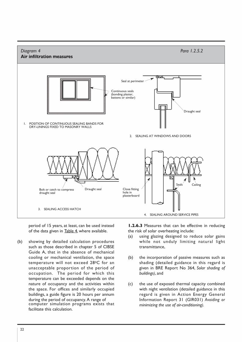
1.2.5.2 For conventional construction measurestaken to ensure this should include:
(a) sealing the void between dry-lining andmasonry walls at the edges of openings such aswindows and doors, and at the junctions withwalls, floors and ceilings (e.g. by continuousbands of bonding plaster or battens),
(b) sealing vapour control membranes in timber-frame constructions,
(c) fitting draught-stripping in the frames ofopenable elements of windows, doors androoflights,
(d) sealing around access or service hatches whichprovide access to unheated voids (loft spaces)from the conditioned space,
(e) ensuring ducting for concealed services issealed at floor and ceiling levels and sealingpiped services where they penetrate orproject into hollow constructions or voids.
Diagram 4 illustrates some of these measures.
1.2.5.3 Additional guidance on appropriatemeasures to limit air infiltration in larger office andcommercial buildings is given in BRE Report BR 448,Air tightness in commercial and public buildings .
Guidance on methods to limit air infiltration throughtwin skin metal cladding and roofing systems iscontained in Steel Construction Institute (SCI)Technical Information Sheet No. 311, The design of
twin-skin metal cladding.
1.2.5.4 Air permeability can be measured by meansof pressure testing of a building prior to completion.The procedure for testing is specified in IS EN13829: 2000 “Thermal performance of buildings:
determination of air permeability of buildings: fan
pressurisation method”. Additional guidance on testingprocedure is given in CIBSE Technical Manual TM 23“Testing Buildings for Air leakage” and BRE document
BR 448 Tightness in Commercial and PublicBuildings.
1.2.5.5 Care should be taken to ensure thatmeasures to limit air infiltration do not negativelyaffect compliance with the ventilation requirementsof Part F and Part J.
1.2.6 AVOIDInG SOLAR
OVERhEATInG
1.2.6.1 Buildings should be designed andconstructed so that:
(a) those occupied spaces that rely on naturalventilation do not risk unacceptable levels ofthermal discomfort due to overheating causedby solar gain, and
(b) those spaces that incorporate mechanicalventilation or cooling do not require excessiveplant capacity to maintain the desired spaceconditions.
Where extensive use of glazing is proposed in thebuilding design, particular care should be exercised toensure compliance with this aspect of theRegulations.
1.2.6.2 Alternative approaches to showingcompliance include:
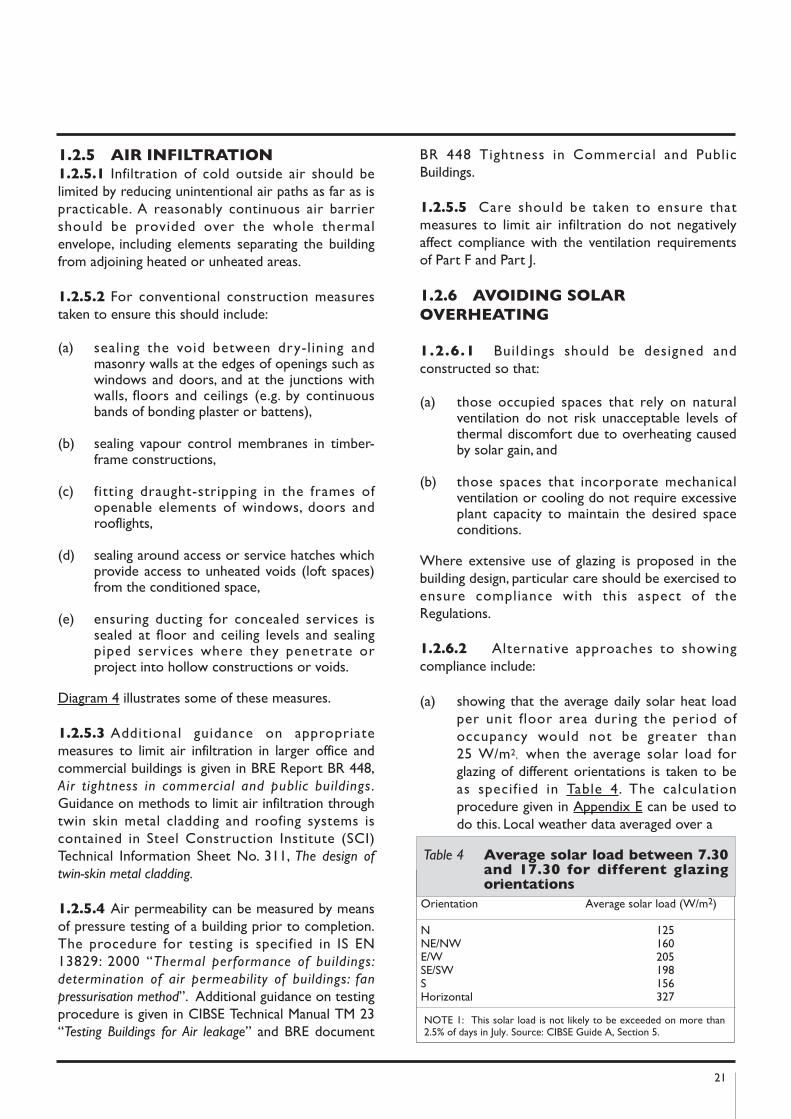
(a) showing that the average daily solar heat loadper unit floor area during the period ofoccupancy would not be greater than25 W/m2, when the average solar load forglazing of different orientations is taken to beas specified in Table 4. The calculationprocedure given in Appendix E can be used todo this. Local weather data averaged over a
Orientation Average solar load (W/m2)
N 125NE/NW 160E/W 205SE/SW 198S 156Horizontal 327
Table 4 Average solar load between 7.30and 17.30 for different glazingorientations
NOTE 1: This solar load is not likely to be exceeded on more than2.5% of days in July. Source: CIBSE Guide A, Section 5.
22
period of 15 years, at least, can be used insteadof the data given in Table 4, where available.
(b) showing by detailed calculation proceduressuch as those described in chapter 5 of CIBSEGuide A, that in the absence of mechanicalcooling or mechanical ventilation, the spacetemperature will not exceed 280C for anunacceptable proportion of the period ofoccupation. The period for which thistemperature can be exceeded depends on thenature of occupancy and the activities withinthe space. For offices and similarly occupiedbuildings, a guide figure is 20 hours per annumduring the period of occupancy. A range of computer simulation programs exists thatfacilitate this calculation.
1.2.6.3 Measures that can be effective in reducingthe risk of solar overheating include:(a) using glazing designed to reduce solar gains
while not unduly l imiting natural l ighttransmittance,
(b) the incorporation of passive measures such asshading (detailed guidance in this regard isgiven in BRE Report No 364, Solar shading of
buildings), and
(c) the use of exposed thermal capacity combinedwith night ventilation (detailed guidance in thisregard is given in Action Energy GeneralInformation Report 31 (GIR031) Avoiding or
minimizing the use of air-conditioning).
Diagram 4 Para 1.2.5.2Air infiltration measures
Continuous seals(bonding plaster,battens or similar)
Seal at perimeter
Draught seal
Draught sealBolt or catch to compressdraught seal
Close fittinghole inplasterboard
Seals
1. POSITION OF CONTINUOUS SEALING BANDS FOR DRY-LININGS FIXED TO MASONRY WALLS
2. SEALING AT WINDOWS AND DOORS
3. SEALING ACCESS HATCH
4. SEALING AROUND SERVICE PIPES
Ceiling
23
1.3: Building Services
1.3.1 hEATInG PLAnT EFFICIEnCyHeating plant should be designed and installed sothat it operates efficiently over the range of loadinglikely to be encountered. Oil and gas fired boilersshould satisfy the efficiency requirements specified inS.I. No. 260 of 1994: European Communities (Efficiency
requirements for new hot water boilers fired with liquid or
gaseous fuels) Regulations, 1994.
1.3.2 COnTROLS FOR SPACE
hEATInG AnD hOT WATER SUPPLy
SySTEMS
1.3.2.1 Space and water heating systems should beeffectively controlled so as to limit energy use bythese systems to that required to satisfy userrequirements and, where appropriate, to protect thebuilding and it’s contents from damage due to lowtemperatures. This section is not intended to applyto control systems for commercial and industrialprocesses.
1.3.2.2 Buildings should be provided with zone,timing and temperature controls such that, for spaceheating, each functional area is maintained at therequired temperature only during the period when itis occupied. Additional space heating controls may beprovided to allow heating during extended unusualoccupation hours and to provide for sufficientbackground heating to prevent condensation or frostdamage when the heating system would otherwisebe switched off.
1.3.2.3 Hot water systems should be designed andprovided with appropriate controls so that they canbe operated efficiently. For efficient operation, hotwater systems should not be over-sized and shouldbe designed to avoid low-load operation of heatingplant. The layout should minimize the length ofcirculation loops and minimize the length anddiameter of dead legs. Designers should haveparticular regard to the need to limit the risk ofpromoting the growth of legionella bacteria. Localinstantaneous heaters should be used, whereappropriate. Consideration should be given to theuse of renewable energy, e.g. solar water heating, andto heat recovery from other processes, whereapplicable. Electric water heating should be avoidedexcept where demand is low.
1.3.2.4 Effective control of space and water heatingcan be achieved as follows:
(a) in buildings with a heating system of maximumoutput not exceeding 100 kW, by following theguidance in Action Energy Good PracticeGuide 132 (GPG132) Heating Controls in small
commercial and mult i -residential bui ldings
published by BRECSU;
(b) in larger or more complex buildings, byfollowing the guidance contained in CIBSEGuide H: Building Control Systems published byCIBSE.
1.3.3 AIR COnDITIOnInG AnD
MEChAnICAL VEnTILATIOn
(ACMV)
1.3.3.1 Buildings that use ACMV systems to treat inexcess of 200 m2 floor area should be designed andconstructed such that:
(a) the form and fabric of the building do notresult in a requirement for excessive installedcapacity of ACMV equipment. In particular, thesuitable specification of glazing ratios and solarshading are an important way to limit coolingrequirements (see Section 1.2.6 above).
(b) components such as fans, pumps andrefrigeration equipment are reasonablyefficient and appropriately sized so as to haveno more capacity for demand and standbythan is necessary for the task.
(c) suitable facilities are provided to manage,control and monitor the operation of theequipment and the systems.
1.3.3.2 ACMV systems can be considered to beadequately sized if the specific fan power (SFP) is lessthan the values given in the following sub-paragraphs.The SFP is the sum of the design total circuit-Wattsof all fans that supply air and exhaust it back tooutdoors (i.e., the sum of supply and extract fans),including all losses through switchgear and controlssuch as inverters, divided by the design ventilationrate through the building.
24
(a) For ACMV systems in new buildings, the SFPshould be no greater than 2.0 W/litre/second.
(b) For new ACMV systems in refurbishedbuildings, or where an existing ACMV systemin an existing building is being substantiallyaltered, the SFP should be no greater than 3.0W/litre/second.
1.3.3.3 These SFP values are appropriate for typicalventilated spaces intended for human occupancy.Where specialist processes are involved or externalpollution levels exceed those normally encounteredand, as a result, greater levels of filtration or aircleaning are required, higher SFPs may beappropriate. In the context of this section “specialistprocesses” can be taken to include any activity whichis not typical of the particular building use, whichaffects a significant area within the building, andwhere the resulting need for heating, ventilation orair conditioning is significantly different to that typicalfor the building. When assessing the performance ofACMV systems, areas where the existence or sizingof these systems is determined by processrequirements should be excluded from theconsidered area, together with the plant capacity, orproportion of the plant capacity, that is provided toservice those areas. Activities and areas in officebuildings considered to represent processrequirements would include:
- Staff restaurants and kitchens;- Large dedicated conference rooms;- Sports facilities;- Dedicated computer or communications
rooms.
1.3.3.4 Mechanical ventilation systems should bereasonably efficient at part load. This can beachieved by providing efficient variable flow controlsystems incorporating, for instance, variable speeddrives or variable pitch axial fans. More detailedguidance is given in Action Energy GeneralInformation, Report 41 (GIR041) Variable flow control,
General Information, published by BRECSU.
1.3.4 InSULATIOn OF STORAGE
VESSELS, PIPES AnD DUCTS
1.3.4.1 This section only applies to pipes, ducts andvessels for the provision of space heating, space
cooling (including chilled water and refrigerant pipework) and hot water supply for normal occupation. Itdoes not apply to pipes, ducts and vessels associatedwith commercial or industrial processes.
1.3.4.2 Hot water storage vessels, pipes and ductsassociated with the provision of heating and hotwater in a building should be insulated to limit heatloss, except where the heat flow through the wall ofthe pipe, duct or vessel is always useful inconditioning the surrounding space. Storage vesselsfor chilled water and refrigerant, and pipes and ductsthat serve air-conditioning systems should beinsulated to limit heat gain from the surroundingenvironment.
1.3.4.3 Provision of insulation to pipes, ducts andstorage vessels, in accordance with the standardsspecified in BS 5422: 2001, should adequately limitheat loss or heat gain, as appropriate. Theappropriate insulation level for storage vessels shouldbe taken as that given in BS 5422: 2001 for flatsurfaces.
1.3.4.4 It should be noted that water pipes andstorage vessels in unheated areas will generally needto be insulated for the purpose of protection againstfreezing. Guidance on suitable protection measures isgiven in BRE Report 262, Thermal insulation: avoidingrisks.
1.3.5 ARTIFICIAL LIGhTInG
1.3.5.1 The guidance given in Paragraphs 1.3.5.2 and1.3.5.3 below need not be applied when the totalinstalled lighting capacity is less than 1000 W. In thissection the term “efficacy” is used to describe theenergy efficiency of a lamp. It is described by theamount of light it produces in lumens with respect tothe power it consumes in Watts.
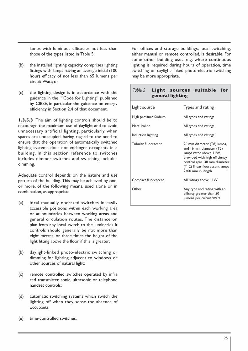
1.3.5.2 General purpose artificial lighting systemsshall be designed and controlled so as to ensure theefficient use of energy for this purpose. Theefficiency of a general lighting system may beconsidered acceptable if it complies with one of thefollowing:
(a) 95 % of the artificial lighting capacity in circuitWatts is provided by lighting fittings which use
25
lamps with luminous efficacies not less thanthose of the types listed in Table 5;
(b) the installed lighting capacity comprises lightingfittings with lamps having an average initial (100hour) efficacy of not less than 65 lumens percircuit Watt; or
(c) the lighting design is in accordance with theguidance in the “Code for Lighting” publishedby CIBSE, in particular the guidance on energyefficiency in Section 2.4 of that document.
1.3.5.3 The aim of lighting controls should be toencourage the maximum use of daylight and to avoidunnecessary artificial lighting, particularly whenspaces are unoccupied, having regard to the need toensure that the operation of automatically switchedlighting systems does not endanger occupants in abuilding. In this section reference to switchesincludes dimmer switches and switching includesdimming.
Adequate control depends on the nature and usepattern of the building. This may be achieved by one,or more, of the following means, used alone or incombination, as appropriate:
(a) local manually operated switches in easilyaccessible positions within each working areaor at boundaries between working areas andgeneral circulation routes. The distance onplan from any local switch to the luminaries itcontrols should generally be not more thaneight metres, or three times the height of thelight fitting above the floor if this is greater;
(b) daylight-linked photo-electric switching ordimming for lighting adjacent to windows orother sources of natural light;
(c) remote controlled switches operated by infrared transmitter, sonic, ultrasonic or telephonehandset controls;
(d) automatic switching systems which switch thelighting off when they sense the absence ofoccupants;
(e) time-controlled switches.
For offices and storage buildings, local switching,either manual or remote controlled, is desirable. Forsome other building uses, e.g. where continuouslighting is required during hours of operation, timeswitching or daylight-linked photo-electric switchingmay be more appropriate.
Light source Types and rating
High pressure Sodium All types and ratings
Metal halide All types and ratings
Induction lighting All types and ratings
Tubular fluorescent 26 mm diameter (T8) lamps, and 16 mm diameter (T5) lamps rated above 11W, provided with high efficiency control gear. 38 mm diameter(T12) linear fluorescent lamps 2400 mm in length
Compact fluorescent All ratings above 11W
Other Any type and rating with an efficacy greater than 50 lumens per circuit Watt.
Table 5 Light sources suitable for
general lighting

26
APPENDICES
27
Appendix A: Calculation of U-Values
GEnERAL
A1.1 General Guidance on the Calculation of U-values is contained in Report BR 443 “Conventionsfor U-value Calculations” 2006. For building elementsand components generally, the method of calculatingU-values is specified in I.S. EN ISO 6946: 1997. U-values of components involving heat transfer to theground, e.g. ground floors with or without floorvoids, basement walls, are calculated by the methodspecified in I.S. EN ISO 13370: 1999. A soil thermalconductivity of 2.0 W/mK should be used, unlessotherwise verified. U-values for windows, doors andshutters may be calculated using I.S. EN ISO 10077-1:2000 or I.S. EN ISO 10077-2: 2000. Information onU-values and guidance on calculation procedurescontained in the 1999 edition of CIBSE Guide A3:Thermal Properties of Building Structures are basedon these standards and may be used to showcompliance with this Part.
A method for assessing U-values of light steelframedconstructions is given in Digest 465 “U-values for light
steel frame construction”, published by BRE. Guidancein relation to the calculation of U-values for variousforms of metal clad construction can be found inTechnical Paper No. 14 “Guidance for the design of
metal roofing and cladding to comply with Approved
Document L2: 2001” published by MCRMA, TechnicalInformation Sheet No. 312, “Metal cladding: U-value
calculation assessing thermal performance of built-up
metal roof and wall cladding systems using rail and
bracket spacers” published by SCI and IP 10/02 “Metal
cladding: assessing thermal performance of built-up
systems which use ‘Z’ spacers” published by BRE.
A1.2 U-values derived by calculation should berounded to two significant figures and relevantinformation on input data should be provided. Whencalculating U-values the effects of timber joists,structural and other framing, mortar bedding,window frames and other small areas where thermalbridging occurs must be taken into account. Similarly,account must be taken of the effect of small areaswhere the insulation level is reduced significantlyrelative to the general level for the component orstructure element under consideration. Thermalbridging may be disregarded, however, where thegeneral thermal resistance does not exceed that inthe bridged area by more than 0.1 m2K/W. Forexample, normal mortar joints need not be taken
into account in calculations for brickwork orconcrete blockwork where the density of the brickor block material is in excess of 1500 kg/m3. Aventilation opening in a wall or roof (other than awindow, rooflight or door opening), may beconsidered as having the same U-value as theelement in which it occurs.
A1.3 Examples of the application of the calculationmethod specified in I.S. EN 6946: 1977 are givenbelow. An example of the calculation of ground floorU-values using I.S. EN ISO 13370: 1999 is also given.
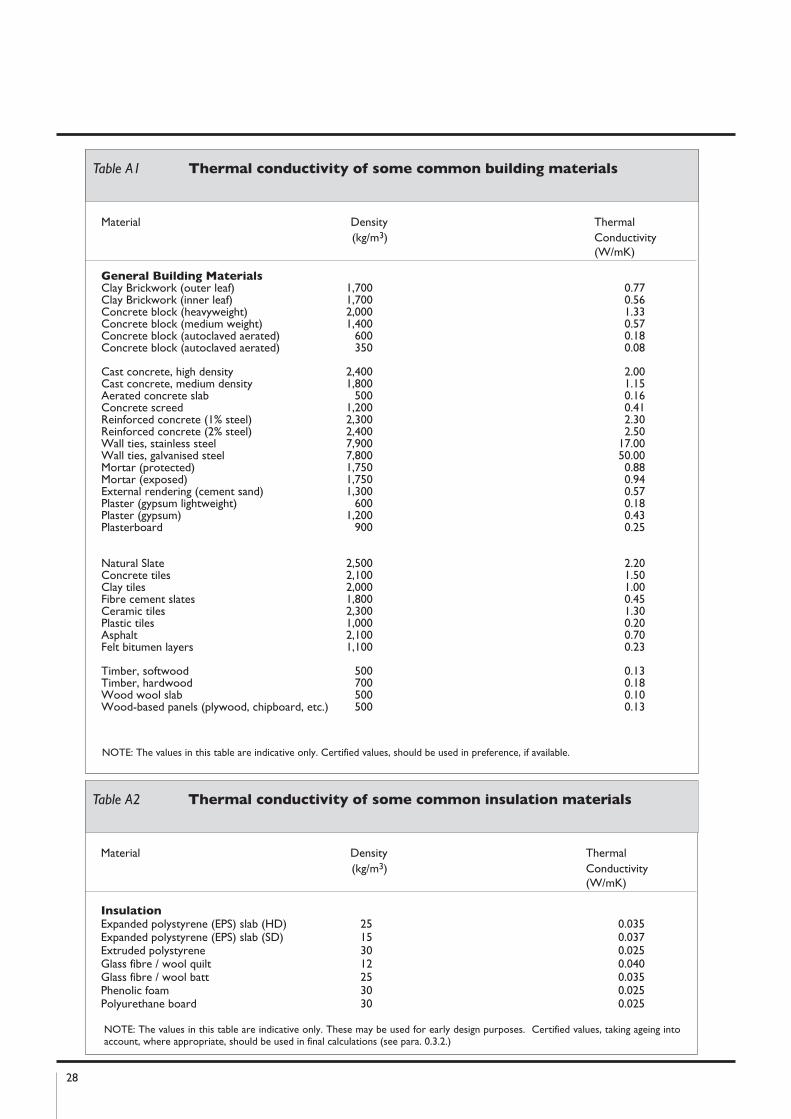
A1.4 Thermal conductivities of common buildingmaterials are given in Table A1 and for commoninsulating materials in Table A2. For the most part,these are taken from I.S. EN 12524: 2000 or CIBSEGuide A3. See Paragraph 0.3.3 regarding applicationof these Tables.
SIMPLE STRUCTURE WIThOUTThERMAL BRIDGInG
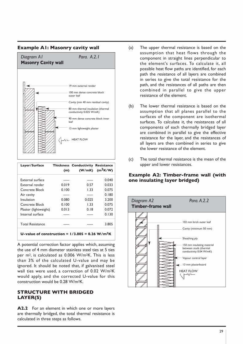
A2.1 To calculate the U-value of a buildingelement (wall or roof) using I.S. EN ISO 6946: 1997,the thermal resistance of each component iscalculated, and these thermal resistances, togetherwith surface resistances as appropriate, are thencombined to yield the total thermal resistance andU-value. The result is corrected to account formechanical fixings (e.g. wall ties) or air gaps ifrequired. For an element consisting of homogenouslayers with no thermal bridging, the total resistance issimply the sum of individual thermal resistances andsurface resistances.
I.S. EN 6946: 1997 provides for corrections to thecalculated U-value. In the case of example A1 (seeDiagram A1), corrections for air gaps in the insulatedlayer and for mechanical fasteners may apply.However, if the total correction is less than 3% of thecalculated value, the correction may be ignored.
In this case no correction for air gaps applies as it isassumed that the insulation boards meet thedimensional standards set out in I.S. EN ISO 6946:1997 and that they are installed without gaps greaterthan 5 mm. The construction involves the use of wallties that penetrate fully through the insulation layer.
28
Material Density Thermal(kg/m3) Conductivity
(W/mK)
General Building MaterialsClay Brickwork (outer leaf) 1,700 0.77Clay Brickwork (inner leaf) 1,700 0.56Concrete block (heavyweight) 2,000 1.33Concrete block (medium weight) 1,400 0.57Concrete block (autoclaved aerated) 600 0.18Concrete block (autoclaved aerated) 350 0.08
Cast concrete, high density 2,400 2.00Cast concrete, medium density 1,800 1.15Aerated concrete slab 500 0.16Concrete screed 1,200 0.41Reinforced concrete (1% steel) 2,300 2.30Reinforced concrete (2% steel) 2,400 2.50Wall ties, stainless steel 7,900 17.00Wall ties, galvanised steel 7,800 50.00Mortar (protected) 1,750 0.88Mortar (exposed) 1,750 0.94External rendering (cement sand) 1,300 0.57Plaster (gypsum lightweight) 600 0.18Plaster (gypsum) 1,200 0.43Plasterboard 900 0.25
Natural Slate 2,500 2.20Concrete tiles 2,100 1.50Clay tiles 2,000 1.00Fibre cement slates 1,800 0.45Ceramic tiles 2,300 1.30Plastic tiles 1,000 0.20Asphalt 2,100 0.70Felt bitumen layers 1,100 0.23
Timber, softwood 500 0.13Timber, hardwood 700 0.18Wood wool slab 500 0.10Wood-based panels (plywood, chipboard, etc.) 500 0.13
Table A1 Thermal conductivity of some common building materials
NOTE: The values in this table are indicative only. Certified values, should be used in preference, if available.
Material Density Thermal(kg/m3) Conductivity
(W/mK)
InsulationExpanded polystyrene (EPS) slab (HD) 25 0.035Expanded polystyrene (EPS) slab (SD) 15 0.037Extruded polystyrene 30 0.025Glass fibre / wool quilt 12 0.040Glass fibre / wool batt 25 0.035Phenolic foam 30 0.025Polyurethane board 30 0.025
NOTE: The values in this table are indicative only. These may be used for early design purposes. Certified values, taking ageing intoaccount, where appropriate, should be used in final calculations (see para. 0.3.2.)
Table A2 Thermal conductivity of some common insulation materials
29
Layer/Surface Thickness Conductivity Resistance
(m) (W/mk) (m2k/W)
External surface ----- ----- 0.040External render 0.019 0.57 0.033Concrete Block 0.100 1.33 0.075Air cavity ----- ----- 0.180Insulation 0.080 0.025 3.200Concrete Block 0.100 1.33 0.075Plaster (lightweight) 0.013 0.18 0.072Internal surface ----- ----- 0.130
Total Resistance ----- ----- 3.805
U-value of construction = 1/3.805 = 0.26 W/m2k
Example A1: Masonry cavity wall
A potential correction factor applies which, assumingthe use of 4 mm diameter stainless steel ties at 5 tiesper m2, is calculated as 0.006 W/m2K. This is lessthan 3% of the calculated U-value and may beignored. It should be noted that, if galvanised steelwall ties were used, a correction of 0.02 W/m2Kwould apply, and the corrected U-value for thisconstruction would be 0.28 W/m2K.
STRUCTURE WITh BRIDGEDLAyER(S)
A2.2 For an element in which one or more layersare thermally bridged, the total thermal resistance iscalculated in three steps as follows.
(a) The upper thermal resistance is based on theassumption that heat flows through thecomponent in straight lines perpendicular tothe element's surfaces. To calculate it, allpossible heat flow paths are identified, for eachpath the resistance of all layers are combinedin series to give the total resistance for thepath, and the resistances of all paths are thencombined in parallel to give the upperresistance of the element.
(b) The lower thermal resistance is based on theassumption that all planes parallel to thesurfaces of the component are isothermalsurfaces. To calculate it, the resistances of allcomponents of each thermally bridged layerare combined in parallel to give the effectiveresistance for the layer, and the resistances ofall layers are then combined in series to givethe lower resistance of the element.
(c) The total thermal resistance is the mean of theupper and lower resistances.
Example A2: Timber-frame wall (withone insulating layer bridged)
Diagram A1 Para. A.2.1Masonry Cavity wall
19 mm external render
100 mm dense concrete blockouter leaf
Cavity (min 40 mm residual cavity)
80 mm thermal insulation (thermalconductivity 0.025 W/mK)
90 mm dense concrete block innerleaf
13 mm lightweight plaster
HEAT FLOW
Diagram A2 Para. A.2.2Timber-frame wall
102 mm brick outer leaf
Cavity (minimum 50 mm)
Sheathing ply
150 mm insulating materialbetween studs (thermalconductivity 0.04 W/mK)
Vapour control layer
13 mm plasterboard
HEAT FLOW
30
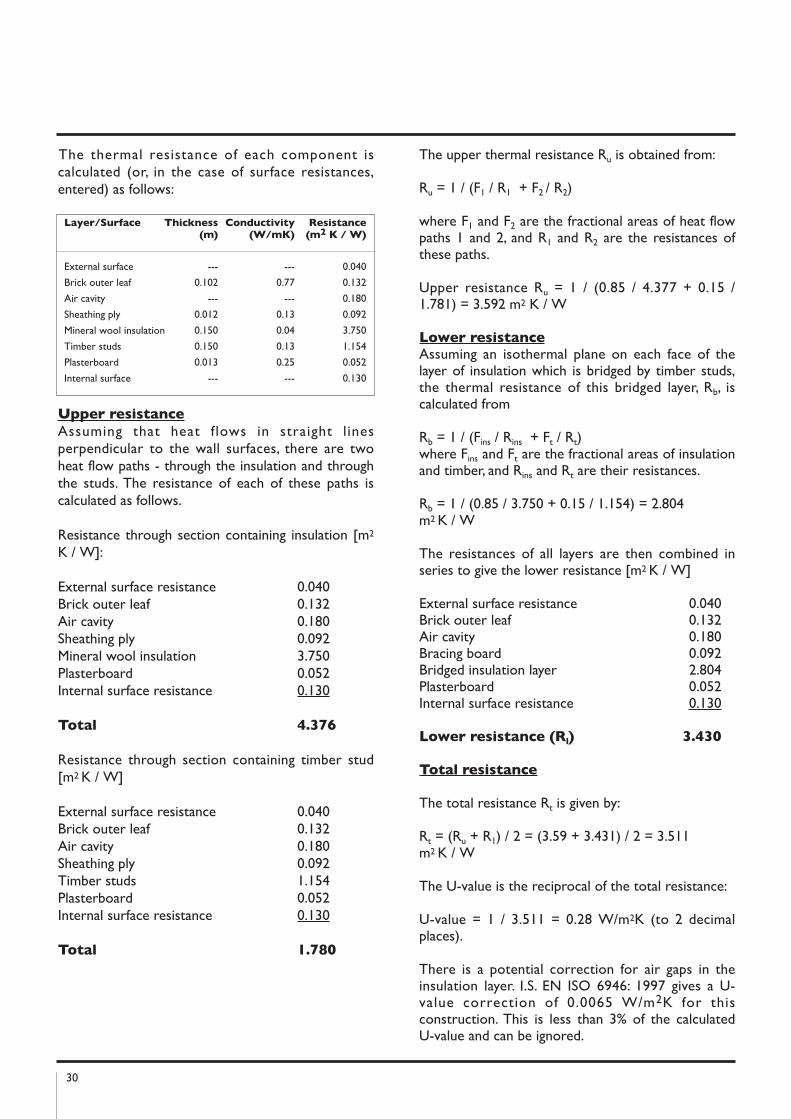
The thermal resistance of each component iscalculated (or, in the case of surface resistances,entered) as follows:
Upper resistance
Assuming that heat flows in straight l inesperpendicular to the wall surfaces, there are twoheat flow paths - through the insulation and throughthe studs. The resistance of each of these paths iscalculated as follows.
Resistance through section containing insulation [m2
K / W]:
External surface resistance 0.040Brick outer leaf 0.132Air cavity 0.180Sheathing ply 0.092Mineral wool insulation 3.750Plasterboard 0.052Internal surface resistance 0.130
Total 4.376
Resistance through section containing timber stud[m2 K / W]
External surface resistance 0.040Brick outer leaf 0.132Air cavity 0.180Sheathing ply 0.092Timber studs 1.154Plasterboard 0.052Internal surface resistance 0.130
Total 1.780
The upper thermal resistance Ru is obtained from:
Ru = 1 / (F1 / R1 + F2 / R2)
where F1 and F2 are the fractional areas of heat flowpaths 1 and 2, and R1 and R2 are the resistances ofthese paths.
Upper resistance Ru = 1 / (0.85 / 4.377 + 0.15 /1.781) = 3.592 m2 K / W
Lower resistanceAssuming an isothermal plane on each face of thelayer of insulation which is bridged by timber studs,the thermal resistance of this bridged layer, Rb, iscalculated from
Rb = 1 / (Fins / Rins + Ft / Rt)where Fins and Ft are the fractional areas of insulationand timber, and Rins and Rt are their resistances.
Rb = 1 / (0.85 / 3.750 + 0.15 / 1.154) = 2.804 m2 K / W
The resistances of all layers are then combined inseries to give the lower resistance [m2 K / W]
External surface resistance 0.040Brick outer leaf 0.132Air cavity 0.180Bracing board 0.092Bridged insulation layer 2.804Plasterboard 0.052Internal surface resistance 0.130
Lower resistance (Rl) 3.430
Total resistance
The total resistance Rt is given by:
Rt = (Ru + R1) / 2 = (3.59 + 3.431) / 2 = 3.511 m2 K / W
The U-value is the reciprocal of the total resistance:
U-value = 1 / 3.511 = 0.28 W/m2K (to 2 decimalplaces).
There is a potential correction for air gaps in theinsulation layer. I.S. EN ISO 6946: 1997 gives a U-value correction of 0.0065 W/m2K for thisconstruction. This is less than 3% of the calculatedU-value and can be ignored.
Layer/Surface Thickness Conductivity Resistance(m) (W/mk) (m2 k / W)
External surface --- --- 0.040
Brick outer leaf 0.102 0.77 0.132
Air cavity --- --- 0.180
Sheathing ply 0.012 0.13 0.092
Mineral wool insulation 0.150 0.04 3.750
Timber studs 0.150 0.13 1.154
Plasterboard 0.013 0.25 0.052
Internal surface --- --- 0.130
31
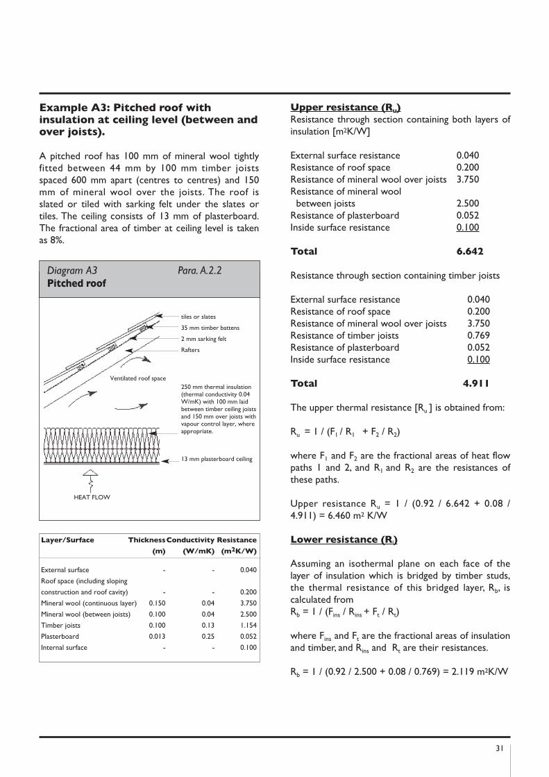
Example A3: Pitched roof withinsulation at ceiling level (between andover joists).
A pitched roof has 100 mm of mineral wool tightlyfitted between 44 mm by 100 mm timber joistsspaced 600 mm apart (centres to centres) and 150mm of mineral wool over the joists. The roof isslated or tiled with sarking felt under the slates ortiles. The ceiling consists of 13 mm of plasterboard.The fractional area of timber at ceiling level is takenas 8%.
Upper resistance (Ru)
Resistance through section containing both layers ofinsulation [m2K/W]
External surface resistance 0.040Resistance of roof space 0.200Resistance of mineral wool over joists 3.750Resistance of mineral wool
between joists 2.500Resistance of plasterboard 0.052Inside surface resistance 0.100
Total 6.642
Resistance through section containing timber joists
External surface resistance 0.040Resistance of roof space 0.200Resistance of mineral wool over joists 3.750Resistance of timber joists 0.769Resistance of plasterboard 0.052Inside surface resistance 0.100
Total 4.911
The upper thermal resistance [Ru ] is obtained from:
Ru = 1 / (F1 / R1 + F2 / R2)
where F1 and F2 are the fractional areas of heat flowpaths 1 and 2, and R1 and R2 are the resistances ofthese paths.
Upper resistance Ru = 1 / (0.92 / 6.642 + 0.08 /4.911) = 6.460 m2 K/W
Lower resistance (Rl)
Assuming an isothermal plane on each face of thelayer of insulation which is bridged by timber studs,the thermal resistance of this bridged layer, Rb, iscalculated from Rb = 1 / (Fins / Rins + Ft / Rt)
where Fins and Ft are the fractional areas of insulationand timber, and Rins and Rt are their resistances.
Rb = 1 / (0.92 / 2.500 + 0.08 / 0.769) = 2.119 m2K/W
Diagram A3 Para. A.2.2 Pitched roof
tiles or slates
35 mm timber battens
2 mm sarking felt
Rafters
250 mm thermal insulation(thermal conductivity 0.04W/mK) with 100 mm laidbetween timber ceiling joistsand 150 mm over joists withvapour control layer, whereappropriate.
13 mm plasterboard ceiling
HEAT FLOW
Ventilated roof space
Layer/Surface ThicknessConductivity Resistance
(m) (W/mk) (m2k/W)
External surface - - 0.040
Roof space (including sloping
construction and roof cavity) - - 0.200
Mineral wool (continuous layer) 0.150 0.04 3.750
Mineral wool (between joists) 0.100 0.04 2.500
Timber joists 0.100 0.13 1.154
Plasterboard 0.013 0.25 0.052
Internal surface - - 0.100
32
The resistances of all layers are then combined inseries to give the lower resistance [m2K/W]
External surface resistance 0.040Resistance of roof space 0.200Resistance of mineral wool over joists 3.750Resistance of bridged layer 2.119Resistance of plasterboard 0.052Inside surface resistance 0.100
Lower resistance (Rl) 6.261
Total resistance
The total resistance Rt is given by:Rt = (Ru + Rl) / 2 = (6.460 + 6.261) / 2 = 6.361m2K/W
The U-value is the reciprocal of the total resistance:U-value = 1 / 6.361 = 0.16 W/m2k (to 2decimal places).
I.S. EN ISO 6946: 1997 does not specify any potentialcorrection for this construction.
GROUnD FLOORS AnD BASEMEnTS
A3.1 The U-value of an uninsulated ground floordepends on a number of factors including floor shapeand area and the nature of the soil beneath the floor.I.S. EN ISO 13370: 1999 deals with the calculation ofU-values of ground floors. Methods are specified forfloors directly on the ground and for floors withvented and unvented sub-floor spaces. I.S. EN ISO13370: 1999 also covers heat loss from basementfloors and walls.
A3.2 In the case of semi-detached or terracedpremises, blocks of flats and similar buildings, thefloor dimensions can be taken as either those of theindividual premises or those of the whole building.Unheated spaces outside the insulated fabric, such asattached porches or garages, should be excludedwhen deriving floor dimensions but the length of thefloor perimeter between the heated building and theunheated space should be included whendetermining the length of exposed perimeter.Where such ancillary areas have the potential tobecome part of the occupied area of the buildingfloors should be insulated to the same level as thebuilding floors unless it is envisaged that a newinsulated floor will be provided when converted.
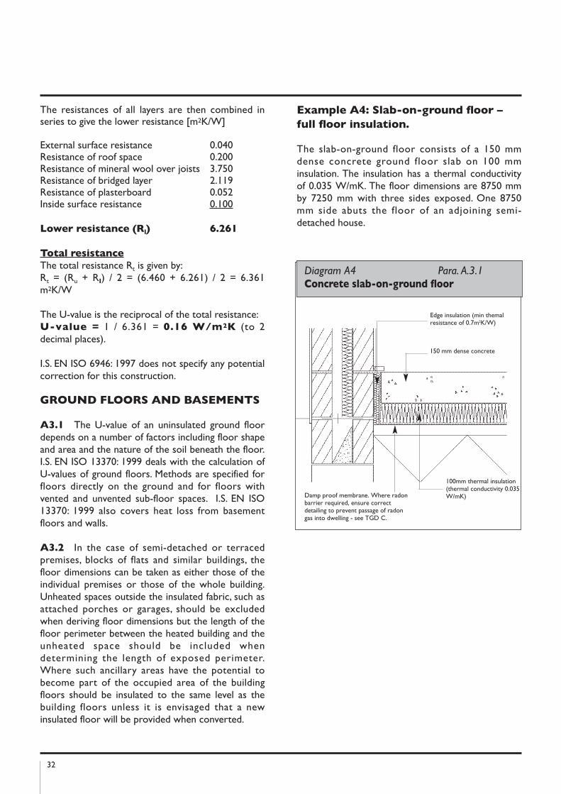
Example A4: Slab-on-ground floor –
full floor insulation.
The slab-on-ground floor consists of a 150 mmdense concrete ground floor slab on 100 mminsulation. The insulation has a thermal conductivityof 0.035 W/mK. The floor dimensions are 8750 mmby 7250 mm with three sides exposed. One 8750mm side abuts the floor of an adjoining semi-detached house.
Diagram A4 Para. A.3.1 Concrete slab-on-ground floor
Edge insulation (min themalresistance of 0.7m2K/W)
150 mm dense concrete
100mm thermal insulation(thermal conductivity 0.035W/mK)Damp proof membrane. Where radon
barrier required, ensure correctdetailing to prevent passage of radongas into dwelling - see TGD C.
33
In accordance with I.S. EN ISO 13370: 1999, thefollowing expression gives the U-value for well-insulated floors:
U = λ/(0.457B’ + dt), whereλ = thermal conductivity of
unfrozen ground (W/mK)B’ = 2A/P (m)dt = w + λ(Rsi + Rf + Rse) (m)A = floor area (m2)P = heat loss perimeter (m)w = wall thickness (m)
Rsi, Rf and Rse are internal surface resistance, floorconstruction (including insulation) resistance andexternal surface resistance respectively. Standardvalues of Rsi and Rse for floors are given as 0.17m2K/W and 0.04 m2K/W respectively. The standardalso states that the thermal resistance of denseconcrete slabs and thin floor coverings may beignored in the calculation and that the thermalconductivity of the ground should be taken as 2.0W/mK unless otherwise known or specified.
Ignoring the thermal resistance of the denseconcrete slab, the thermal resistance of the floorconstruction (Rf) is equal to the thermal resistanceof the insulation alone, i.e. 0.1/0.035 or 2.857 m2K/W.Taking the wall thickness as 300 mm, this gives
dt = 0.30 + 2.0(0.17 + 2.857 + 0.04) = 6.434 m.
Also B’ = 2(8.75 x 7.25) / (8.75 + 7.25 + 7.25) = 5.457 m
Therefore U = 2.0 / ((0.457 x 5.457) + 6.434) = 0.22 W/m2K.
The edge insulation to the slab is provided toprevent thermal bridging at the edge of the slab. I.S.EN ISO 13370: 1999 does not consider this edgeinsulation as contributing to the overall floorinsulation and thus reducing the floor U-value.However, edge insulation, which extends below theexternal ground level, is considered to contribute toa reduction in floor U-value and a method of takingthis into account is included in the standard.Foundation walls of insulating lightweight concretemay be taken as edge insulation for this purpose.
ELEMEnTS ADjACEnT TOUnhEATED SPACES
A4.1 As indicated in Paragraph 0.3.5, theprocedure for the calculation of U-values ofelements adjacent to unheated spaces (previouslyreferred to as semi-exposed elements) is given in I.S.EN ISO 6946: 1997 and I.S. EN ISO 13789: 2000.
The following formulae may be used to deriveelemental U-values (taking the unheated space intoaccount) for typical housing situations irrespective ofthe precise dimensions of the unheated space.
Uo = 1 /(1/U-Ru) or U = 1 /(1/Uo+Ru)
Where: U – U-value of element adjacent tounheated space (W/m2K), taking theeffect of the unheated space intoaccount.
Uo – U-value of the element betweenheated and unheated spaces(W/m2K) calculated as if there wasno unheated space adjacent to theelement.
Ru – effective thermal resistance ofunheated space inclusive of allexternal elements (m2 K / W).
This procedure can be used when the precise detailson the structure providing an unheated space are notavailable, or not crucial.
Ru for typical unheated structures (including garages,access corridors to flats and unheatedconservatories) are given in Tables A3, A4 and A5.
Table A5 applies only where a conservatory - stylesunroom is not treated as an integral part of thedwelling i.e. is treated as an extension.
In the case of room-in-roof construction, the U-valueof the walls of the room-in-roof construction and ofthe ceiling of the room below the space adjacent tothese walls can be calculated using this procedure.See Diagram A5.
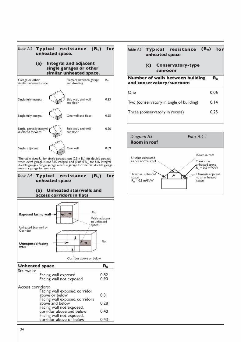
34
number of walls between building Ru
and conservatory/sunroom
One 0.06
Two (conservatory in angle of building) 0.14
Three (conservatory in recess) 0.25
Room in roof
Elements adjacentto an unheatedspace
U-value calculatedas per normal roof
Treat as unheatedspace Ru = 0.5 m2K/W
Diagram A5 Para. A.4.1 Room in roof
Treat as inunheated spaceRu = 0.5 m2K/W
Exposed facing wall
Unheated Stairwell orCorridor
Unexposed facingwall
Flat
Walls adjacentto unheatedspace
Corridor above or below
Flat
Unheated space Ru
Stairwells:Facing wall exposed 0.82Facing wall not exposed 0.90
Access corridors:Facing wall exposed, corridor above or below 0.31Facing wall exposed, corridors above and below 0.28Facing wall not exposed, corridor above and below 0.40Facing wall not exposed, corridor above or below 0.43
Table A3 Typical resistance (Ru) forunheated space.
(a) Integral and adjacent single garages or other similar unheated space.
Garage or other similar unheated space
Single fully integral
Single fully integral
Single, partially integraldisplaced forward
Single, adjacent
Element between garage and dwelling
Side wall, end wall and floor
One wall and floor
Side wall, end wall and floor
One wall
Ru
0.33
0.25
0.26
0.09
The table gives Ru for single garages; use (0.5 x Ru) for double garageswhen extra garage is not fully integral, and (0.85 x Ru) for fully integraldouble garages. Single garage means a garage for one car; double garagemeans a garage for two cars.
Table A4 Typical resistance (Ru) forunheated space
(b) Unheated stairwells and access corridors in flats
Table A5 Typical resistance (Ru) for
unheated space
(c) Conservatory-type
sunroom
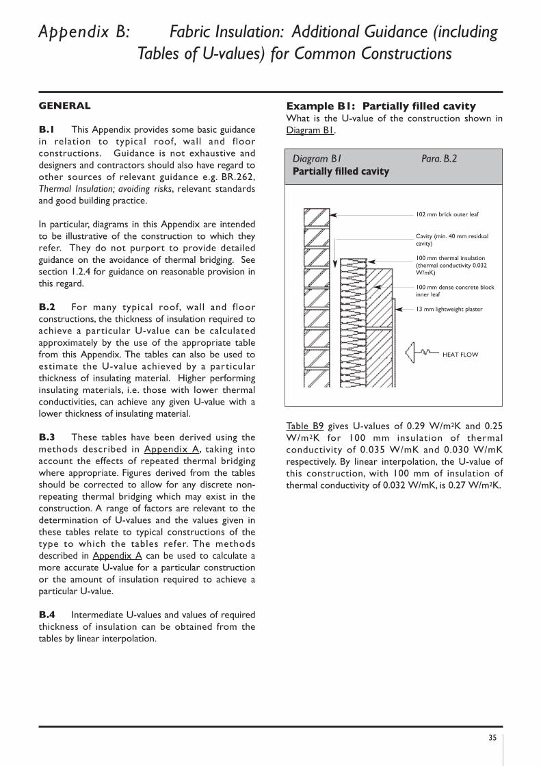
35
GEnERAL
B.1 This Appendix provides some basic guidancein relation to typical roof, wall and floorconstructions. Guidance is not exhaustive anddesigners and contractors should also have regard toother sources of relevant guidance e.g. BR.262,Thermal Insulation; avoiding risks, relevant standardsand good building practice.
In particular, diagrams in this Appendix are intendedto be illustrative of the construction to which theyrefer. They do not purport to provide detailedguidance on the avoidance of thermal bridging. Seesection 1.2.4 for guidance on reasonable provision inthis regard.
B.2 For many typical roof, wall and floorconstructions, the thickness of insulation required toachieve a particular U-value can be calculatedapproximately by the use of the appropriate tablefrom this Appendix. The tables can also be used toestimate the U-value achieved by a particularthickness of insulating material. Higher performinginsulating materials, i.e. those with lower thermalconductivities, can achieve any given U-value with alower thickness of insulating material.
B.3 These tables have been derived using themethods described in Appendix A, taking intoaccount the effects of repeated thermal bridgingwhere appropriate. Figures derived from the tablesshould be corrected to allow for any discrete non-repeating thermal bridging which may exist in theconstruction. A range of factors are relevant to thedetermination of U-values and the values given inthese tables relate to typical constructions of thetype to which the tables refer. The methodsdescribed in Appendix A can be used to calculate amore accurate U-value for a particular constructionor the amount of insulation required to achieve aparticular U-value.
B.4 Intermediate U-values and values of requiredthickness of insulation can be obtained from thetables by linear interpolation.
Example B1: Partially filled cavity What is the U-value of the construction shown inDiagram B1.
Table B9 gives U-values of 0.29 W/m2K and 0.25W/m2K for 100 mm insulation of thermalconductivity of 0.035 W/mK and 0.030 W/mK respectively. By linear interpolation, the U-value ofthis construction, with 100 mm of insulation ofthermal conductivity of 0.032 W/mK, is 0.27 W/m2K.
Appendix B: Fabric Insulation: Additional Guidance (including
Tables of U-values) for Common Constructions
Diagram B1 Para. B.2 Partially filled cavity
102 mm brick outer leaf
Cavity (min. 40 mm residualcavity)
100 mm thermal insulation(thermal conductivity 0.032W/mK)
100 mm dense concrete blockinner leaf
13 mm lightweight plaster
HEAT FLOW
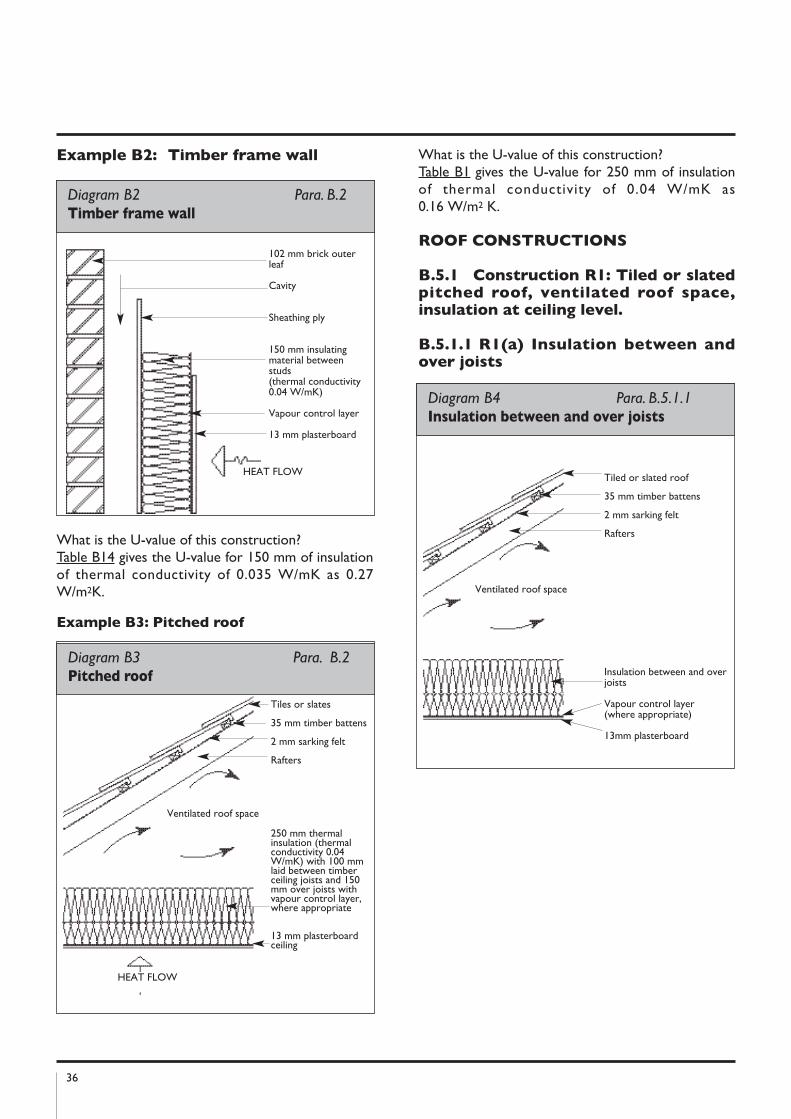
36
Example B2: Timber frame wall
What is the U-value of this construction?Table B14 gives the U-value for 150 mm of insulationof thermal conductivity of 0.035 W/mK as 0.27W/m2K.
Example B3: Pitched roof
What is the U-value of this construction?Table B1 gives the U-value for 250 mm of insulationof thermal conductivity of 0.04 W/mK as0.16 W/m2 K.
ROOF COnSTRUCTIOnS
B.5.1 Construction R1: Tiled or slatedpitched roof, ventilated roof space,insulation at ceiling level.
B.5.1.1 R1(a) Insulation between andover joists
Diagram B4 Para. B.5.1.1 Insulation between and over joists
Tiled or slated roof
35 mm timber battens
2 mm sarking felt
Rafters
Insulation between and overjoists
Vapour control layer(where appropriate)
13mm plasterboard
Ventilated roof space
Tiles or slates
35 mm timber battens
2 mm sarking felt
Rafters
250 mm thermalinsulation (thermalconductivity 0.04W/mK) with 100 mmlaid between timberceiling joists and 150mm over joists withvapour control layer,where appropriate
13 mm plasterboardceiling
HEAT FLOW
Ventilated roof space
Diagram B3 Para. B.2 Pitched roof
Diagram B2 Para. B.2 Timber frame wall
102 mm brick outerleaf
Cavity
Sheathing ply
150 mm insulatingmaterial betweenstuds(thermal conductivity0.04 W/mK)
Vapour control layer
13 mm plasterboard
HEAT FLOW
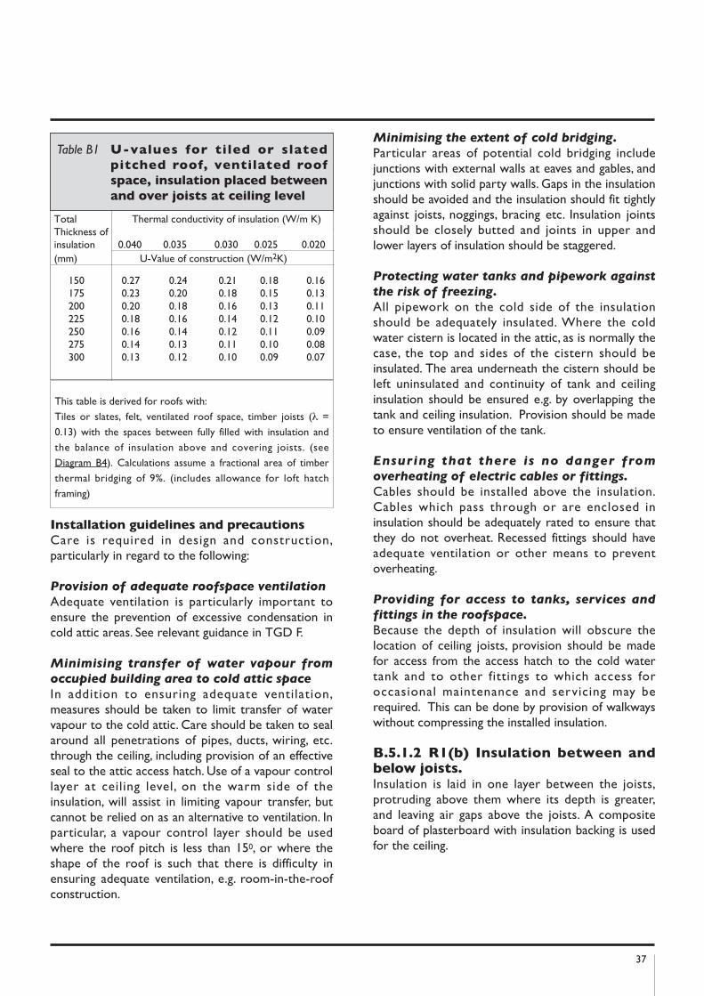
37
Installation guidelines and precautions
Care is required in design and construction,particularly in regard to the following:
Provision of adequate roofspace ventilation
Adequate ventilation is particularly important toensure the prevention of excessive condensation incold attic areas. See relevant guidance in TGD F.
Minimising transfer of water vapour from
occupied building area to cold attic space
In addition to ensuring adequate ventilation,measures should be taken to limit transfer of watervapour to the cold attic. Care should be taken to sealaround all penetrations of pipes, ducts, wiring, etc.through the ceiling, including provision of an effectiveseal to the attic access hatch. Use of a vapour controllayer at ceiling level, on the warm side of theinsulation, will assist in limiting vapour transfer, butcannot be relied on as an alternative to ventilation. Inparticular, a vapour control layer should be usedwhere the roof pitch is less than 150, or where theshape of the roof is such that there is difficulty inensuring adequate ventilation, e.g. room-in-the-roofconstruction.
Minimising the extent of cold bridging.
Particular areas of potential cold bridging includejunctions with external walls at eaves and gables, andjunctions with solid party walls. Gaps in the insulationshould be avoided and the insulation should fit tightlyagainst joists, noggings, bracing etc. Insulation jointsshould be closely butted and joints in upper andlower layers of insulation should be staggered.
Protecting water tanks and pipework against
the risk of freezing.
All pipework on the cold side of the insulationshould be adequately insulated. Where the coldwater cistern is located in the attic, as is normally thecase, the top and sides of the cistern should beinsulated. The area underneath the cistern should beleft uninsulated and continuity of tank and ceilinginsulation should be ensured e.g. by overlapping thetank and ceiling insulation. Provision should be madeto ensure ventilation of the tank.
Ensuring that there is no danger from
overheating of electric cables or fittings.
Cables should be installed above the insulation.Cables which pass through or are enclosed ininsulation should be adequately rated to ensure thatthey do not overheat. Recessed fittings should haveadequate ventilation or other means to preventoverheating.
Providing for access to tanks, services and
fittings in the roofspace.
Because the depth of insulation will obscure thelocation of ceiling joists, provision should be madefor access from the access hatch to the cold watertank and to other fittings to which access foroccasional maintenance and servicing may berequired. This can be done by provision of walkwayswithout compressing the installed insulation.
B.5.1.2 R1(b) Insulation between andbelow joists.Insulation is laid in one layer between the joists,protruding above them where its depth is greater,and leaving air gaps above the joists. A compositeboard of plasterboard with insulation backing is usedfor the ceiling.
Total Thermal conductivity of insulation (W/m K)Thickness ofinsulation 0.040 0.035 0.030 0.025 0.020(mm) U-Value of construction (W/m2K)
150 0.27 0.24 0.21 0.18 0.16175 0.23 0.20 0.18 0.15 0.13200 0.20 0.18 0.16 0.13 0.11225 0.18 0.16 0.14 0.12 0.10250 0.16 0.14 0.12 0.11 0.09275 0.14 0.13 0.11 0.10 0.08300 0.13 0.12 0.10 0.09 0.07
Table B1 U-values for tiled or slated
pitched roof, ventilated roof
space, insulation placed between
and over joists at ceiling level
This table is derived for roofs with:
Tiles or slates, felt, ventilated roof space, timber joists (λ =
0.13) with the spaces between fully filled with insulation and
the balance of insulation above and covering joists. (see
Diagram B4). Calculations assume a fractional area of timber
thermal bridging of 9%. (includes allowance for loft hatch
framing)
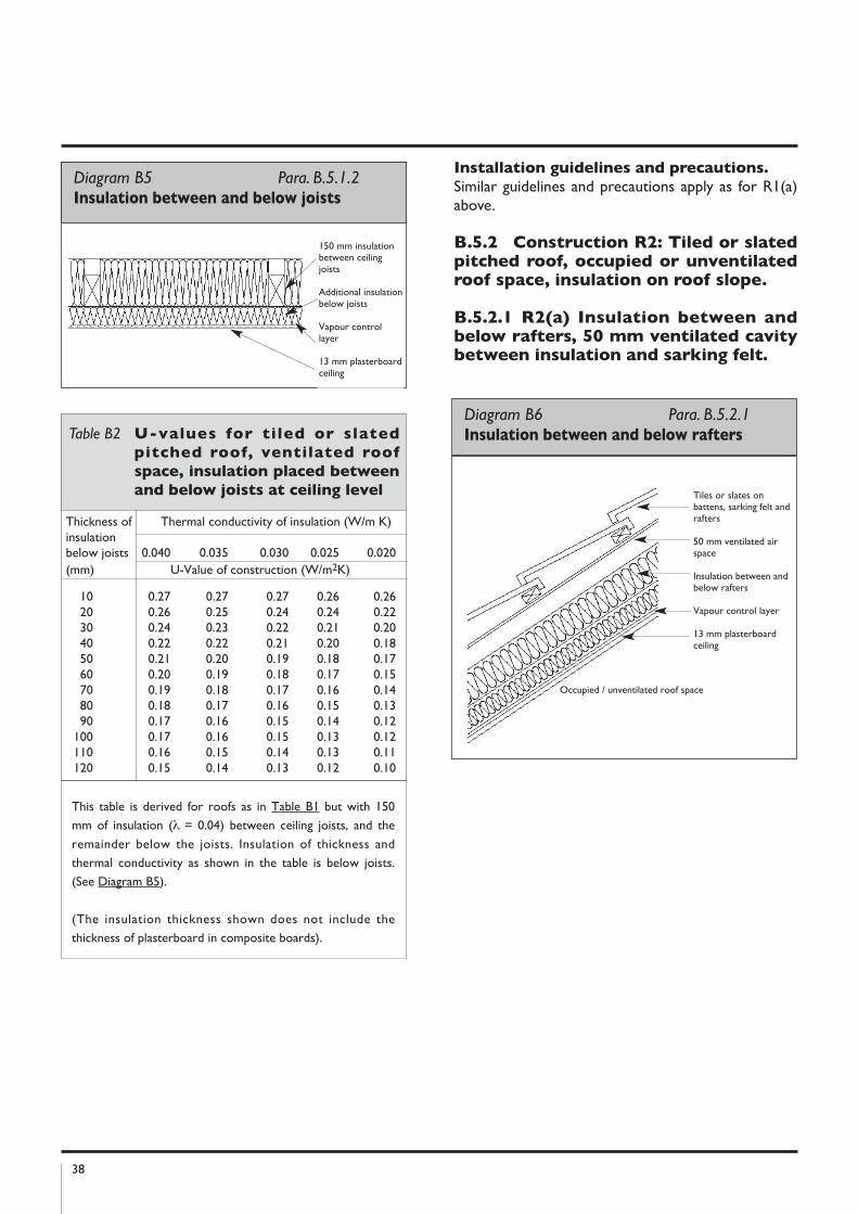
38
Installation guidelines and precautions.
Similar guidelines and precautions apply as for R1(a)above.
B.5.2 Construction R2: Tiled or slatedpitched roof, occupied or unventilatedroof space, insulation on roof slope.
B.5.2.1 R2(a) Insulation between andbelow rafters, 50 mm ventilated cavitybetween insulation and sarking felt.
Diagram B6 Para. B.5.2.1Insulation between and below rafters
Tiles or slates onbattens, sarking felt andrafters
50 mm ventilated airspace
Insulation between andbelow rafters
Vapour control layer
13 mm plasterboardceiling
Occupied / unventilated roof space
Thickness of Thermal conductivity of insulation (W/m K)insulationbelow joists 0.040 0.035 0.030 0.025 0.020(mm) U-Value of construction (W/m2K)
10 0.27 0.27 0.27 0.26 0.2620 0.26 0.25 0.24 0.24 0.2230 0.24 0.23 0.22 0.21 0.2040 0.22 0.22 0.21 0.20 0.1850 0.21 0.20 0.19 0.18 0.1760 0.20 0.19 0.18 0.17 0.1570 0.19 0.18 0.17 0.16 0.1480 0.18 0.17 0.16 0.15 0.1390 0.17 0.16 0.15 0.14 0.12
100 0.17 0.16 0.15 0.13 0.12110 0.16 0.15 0.14 0.13 0.11120 0.15 0.14 0.13 0.12 0.10
Table B2 U-values for tiled or slated
pitched roof, ventilated roof
space, insulation placed between
and below joists at ceiling level
Diagram B5 Para. B.5.1.2 Insulation between and below joists
150 mm insulationbetween ceilingjoists
Additional insulationbelow joists
Vapour controllayer
13 mm plasterboardceiling
This table is derived for roofs as in Table B1 but with 150
mm of insulation (λ = 0.04) between ceiling joists, and the
remainder below the joists. Insulation of thickness and
thermal conductivity as shown in the table is below joists.
(See Diagram B5).
(The insulation thickness shown does not include the
thickness of plasterboard in composite boards).
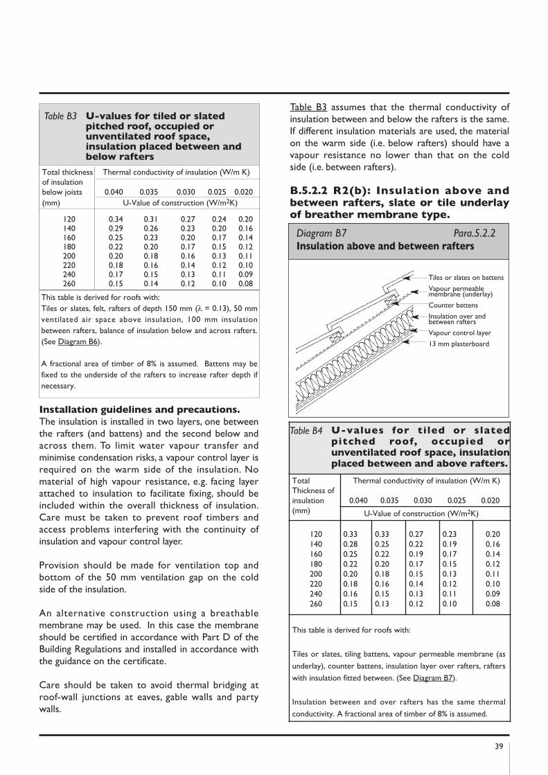
39
Total thickness Thermal conductivity of insulation (W/m K)of insulationbelow joists 0.040 0.035 0.030 0.025 0.020(mm) U-Value of construction (W/m2K)
120 0.34 0.31 0.27 0.24 0.20140 0.29 0.26 0.23 0.20 0.16160 0.25 0.23 0.20 0.17 0.14180 0.22 0.20 0.17 0.15 0.12200 0.20 0.18 0.16 0.13 0.11220 0.18 0.16 0.14 0.12 0.10240 0.17 0.15 0.13 0.11 0.09260 0.15 0.14 0.12 0.10 0.08
Installation guidelines and precautions.
The insulation is installed in two layers, one betweenthe rafters (and battens) and the second below andacross them. To limit water vapour transfer andminimise condensation risks, a vapour control layer isrequired on the warm side of the insulation. Nomaterial of high vapour resistance, e.g. facing layerattached to insulation to facilitate fixing, should beincluded within the overall thickness of insulation.Care must be taken to prevent roof timbers andaccess problems interfering with the continuity ofinsulation and vapour control layer.
Provision should be made for ventilation top andbottom of the 50 mm ventilation gap on the coldside of the insulation.
An alternative construction using a breathablemembrane may be used. In this case the membraneshould be certified in accordance with Part D of theBuilding Regulations and installed in accordance withthe guidance on the certificate.
Care should be taken to avoid thermal bridging atroof-wall junctions at eaves, gable walls and partywalls.
Table B3 assumes that the thermal conductivity ofinsulation between and below the rafters is the same.If different insulation materials are used, the materialon the warm side (i.e. below rafters) should have avapour resistance no lower than that on the coldside (i.e. between rafters).
B.5.2.2 R2(b): Insulation above andbetween rafters, slate or tile underlayof breather membrane type.
Table B3 U-values for tiled or slatedpitched roof, occupied orunventilated roof space,insulation placed between andbelow rafters
Diagram B7 Para.5.2.2 Insulation above and between rafters
Tiles or slates on battens
Vapour permeablemembrane (underlay)
Counter battens
Insulation over andbetween rafters
Vapour control layer
13 mm plasterboard
This table is derived for roofs with:Tiles or slates, felt, rafters of depth 150 mm (λ = 0.13), 50 mmventilated air space above insulation, 100 mm insulationbetween rafters, balance of insulation below and across rafters.(See Diagram B6).
A fractional area of timber of 8% is assumed. Battens may befixed to the underside of the rafters to increase rafter depth ifnecessary.
Table B4 U-values for tiled or slatedpitched roof, occupied orunventilated roof space, insulationplaced between and above rafters.
TotalThickness ofinsulation(mm)
Thermal conductivity of insulation (W/m K)
0.040 0.035 0.030 0.025 0.020
U-Value of construction (W/m2K)
120140160180200220240260
0.330.280.250.220.200.180.160.15
0.330.250.220.200.180.160.150.13
0.270.220.190.170.150.140.130.12
0.230.190.170.150.130.120.110.10
0.200.160.140.120.110.100.090.08
This table is derived for roofs with:
Tiles or slates, tiling battens, vapour permeable membrane (as
underlay), counter battens, insulation layer over rafters, rafters
with insulation fitted between. (See Diagram B7).
Insulation between and over rafters has the same thermal
conductivity. A fractional area of timber of 8% is assumed.
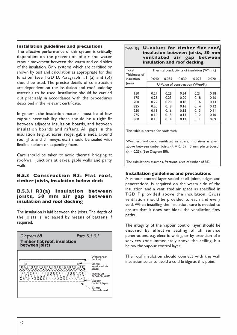
40
Installation guidelines and precautions
The effective performance of this system is criticallydependent on the prevention of air and watervapour movement between the warm and cold sidesof the insulation. Only systems which are certified orshown by test and calculation as appropriate for thisfunction, (see TGD D, Paragraph 1.1 (a) and (b))should be used. The precise details of constructionare dependent on the insulation and roof underlaymaterials to be used. Installation should be carriedout precisely in accordance with the proceduresdescribed in the relevant certificate.
In general, the insulation material must be of lowvapour permeability, there should be a tight fitbetween adjacent insulation boards, and betweeninsulation boards and rafters. All gaps in theinsulation (e.g. at eaves, ridge, gable ends, aroundrooflights and chimneys, etc.) should be sealed withflexible sealant or expanding foam.
Care should be taken to avoid thermal bridging atroof-wall junctions at eaves, gable walls and partywalls.
B.5.3 Construction R3: Flat roof,timber joists, insulation below deck
B.5.3.1 R3(a) Insulation betweenjoists, 50 mm air gap betweeninsulation and roof decking
The insulation is laid between the joists. The depth ofthe joists is increased by means of battens ifrequired.
Installation guidelines and precautions
A vapour control layer sealed at all joints, edges andpenetrations, is required on the warm side of theinsulation, and a ventilated air space as specified inTGD F provided above the insulation. Crossventilation should be provided to each and everyvoid. When installing the insulation, care is needed toensure that it does not block the ventilation flowpaths.
The integrity of the vapour control layer should beensured by effective sealing of all servicepenetrations, e.g. electric wiring, or by provision of aservices zone immediately above the ceiling, butbelow the vapour control layer.
The roof insulation should connect with the wallinsulation so as to avoid a cold bridge at this point.
Diagram B8 Para. B.5.3.1 Timber flat roof, insulation between joists
Waterproofdecking
50 mmventilated airspace
Insulationbetween joists
Vapourcontrol layer
13 mmplasterboard
Table B5 U-values for timber flat roof,insulation between joists, 50 mmventilated air gap betweeninsulation and roof decking.
TotalThickness ofinsulation(mm)
Thermal conductivity of insulation (W/m K)
0.040 0.035 0.030 0.025 0.020
U-Value of construction (W/m2K)
150175200225250275300
0.290.250.220.200.180.160.15
0.260.230.200.180.160.150.14
0.240.200.180.160.150.130.12
0.210.180.160.140.130.120.11
0.180.160.140.120.110.100.09
This table is derived for roofs with:
Weatherproof deck, ventilated air space, insulation as given
above between timber joists (λ = 0.13), 13 mm plasterboard
(λ = 0.25). (See Diagram B8).
The calculations assume a fractional area of timber of 8%.
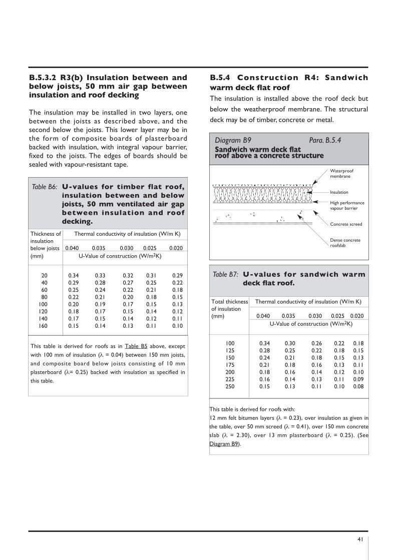
41
B.5.3.2 R3(b) Insulation between andbelow joists, 50 mm air gap betweeninsulation and roof decking
The insulation may be installed in two layers, onebetween the joists as described above, and thesecond below the joists. This lower layer may be inthe form of composite boards of plasterboardbacked with insulation, with integral vapour barrier,fixed to the joists. The edges of boards should besealed with vapour-resistant tape.
B.5.4 Construction R4: Sandwich
warm deck flat roof
The insulation is installed above the roof deck but
below the weatherproof membrane. The structural
deck may be of timber, concrete or metal.
Thickness of Thermal conductivity of insulation (W/m K)insulationbelow joists 0.040 0.035 0.030 0.025 0.020(mm) U-Value of construction (W/m2K)
20 0.34 0.33 0.32 0.31 0.2940 0.29 0.28 0.27 0.25 0.2260 0.25 0.24 0.22 0.21 0.1880 0.22 0.21 0.20 0.18 0.15
100 0.20 0.19 0.17 0.15 0.13120 0.18 0.17 0.15 0.14 0.12140 0.17 0.15 0.14 0.12 0.11160 0.15 0.14 0.13 0.11 0.10
Table B6: U-values for timber flat roof,
insulation between and below
joists, 50 mm ventilated air gap
between insulation and roof
decking.
This table is derived for roofs as in Table B5 above, except
with 100 mm of insulation (λ = 0.04) between 150 mm joists,
and composite board below joists consisting of 10 mm
plasterboard (λ= 0.25) backed with insulation as specified in
this table.
Diagram B9 Para. B.5.4 Sandwich warm deck flat roof above a concrete structure
Waterproofmembrane
Insulation
High performancevapour barrier
Concrete screed
Dense concreteroofslab
Total thickness Thermal conductivity of insulation (W/m K)of insulation(mm) 0.040 0.035 0.030 0.025 0.020
U-Value of construction (W/m2K)
100 0.34 0.30 0.26 0.22 0.18125 0.28 0.25 0.22 0.18 0.15150 0.24 0.21 0.18 0.15 0.13175 0.21 0.18 0.16 0.13 0.11200 0.18 0.16 0.14 0.12 0.10225 0.16 0.14 0.13 0.11 0.09250 0.15 0.13 0.11 0.10 0.08
Table B7: U-values for sandwich warm
deck flat roof.
This table is derived for roofs with:
12 mm felt bitumen layers (λ = 0.23), over insulation as given in
the table, over 50 mm screed (λ = 0.41), over 150 mm concrete
slab (λ = 2.30), over 13 mm plasterboard (λ = 0.25). (See
Diagram B9).
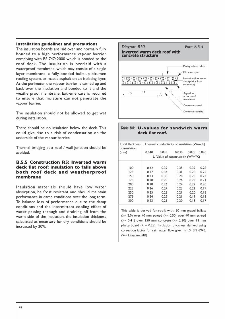
42
Installation guidelines and precautions
The insulation boards are laid over and normally fullybonded to a high performance vapour barriercomplying with BS 747: 2000 which is bonded to theroof deck. The insulation is overlaid with awaterproof membrane, which may consist of a singlelayer membrane, a fully-bonded built-up bitumenroofing system, or mastic asphalt on an isolating layer.At the perimeter, the vapour barrier is turned up andback over the insulation and bonded to it and theweatherproof membrane. Extreme care is requiredto ensure that moisture can not penetrate thevapour barrier.
The insulation should not be allowed to get wetduring installation.
There should be no insulation below the deck. Thiscould give rise to a risk of condensation on theunderside of the vapour barrier.
Thermal bridging at a roof / wall junction should beavoided.
B.5.5 Construction R5: Inverted warmdeck flat roof: insulation to falls aboveboth roof deck and weatherproofmembrane
Insulation materials should have low waterabsorption, be frost resistant and should maintainperformance in damp conditions over the long term.To balance loss of performance due to the dampconditions and the intermittent cooling effect ofwater passing through and draining off from thewarm side of the insulation, the insulation thicknesscalculated as necessary for dry conditions should beincreased by 20%.
Total thickness Thermal conductivity of insulation (W/m K)of insulation(mm) 0.040 0.035 0.030 0.025 0.020
U-Value of construction (W/m2K)
100 0.42 0.39 0.35 0.32 0.28125 0.37 0.34 0.31 0.28 0.25150 0.33 0.30 0.28 0.25 0.23175 0.30 0.28 0.26 0.23 0.21200 0.28 0.26 0.24 0.22 0.20225 0.26 0.24 0.23 0.21 0.19250 0.25 0.23 0.21 0.20 0.18275 0.24 0.22 0.21 0.19 0.18300 0.23 0.21 0.20 0.18 0.17
Table B8: U-values for sandwich warm
deck flat roof.
Diagram B10 Para. B.5.5 Inverted warm deck roof with concrete structure
Paving slab or ballast
Filtration layer
Insulation (low waterabsorptivity, frostresistance)
Asphalt orwaterproofmembrane
Concrete screed
Concrete roofslab
This table is derived for roofs with: 50 mm gravel ballast
(λ= 2.0) over 40 mm screed (λ= 0.50) over 40 mm screed
(λ= 0.41) over 150 mm concrete (λ= 2.30) over 13 mm
plasterboard (λ = 0.25). Insulation thickness derived using
correction factor for rain water flow given in I.S. EN 6946.
(See Diagram B10).
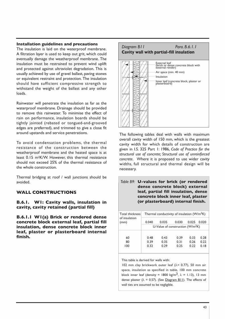
43
Installation guidelines and precautions
The insulation is laid on the waterproof membrane.A filtration layer is used to keep out grit, which couldeventually damage the weatherproof membrane. Theinsulation must be restrained to prevent wind upliftand protected against ultraviolet degradation. This isusually achieved by use of gravel ballast, paving stonesor equivalent restraint and protection. The insulationshould have sufficient compressive strength towithstand the weight of the ballast and any otherloads.
Rainwater will penetrate the insulation as far as thewaterproof membrane. Drainage should be providedto remove this rainwater. To minimise the effect ofrain on performance, insulation boards should betightly jointed (rebated or tongued-and-groovededges are preferred), and trimmed to give a close fitaround upstands and service penetrations.
To avoid condensation problems, the thermalresistance of the construction between theweatherproof membrane and the heated space is atleast 0.15 m2K/W. However, this thermal resistanceshould not exceed 25% of the thermal resistance ofthe whole construction.
Thermal bridging at roof / wall junctions should beavoided.
WALL COnSTRUCTIOnS
B.6.1. W1: Cavity walls, insulation incavity, cavity retained (partial fill)
B.6.1.1 W1(a) Brick or rendered denseconcrete block external leaf, partial fillinsulation, dense concrete block innerleaf, plaster or plasterboard internalfinish.
The following tables deal with walls with maximumoverall cavity width of 150 mm, which is the greatestcavity width for which details of construction aregiven in I.S. 325 Part 1: 1986, Code of Practice for the
structural use of concrete; Structural use of unreinforced
concrete. Where it is proposed to use wider cavitywidths, full structural and thermal design will benecessary.
Diagram B11 Para. B.6.1.1 Cavity wall with partial-fill insulation
External leaf (brick or dense concrete block withexternal render)
Air space (min. 40 mm)
Insulation
Inner leaf (concrete block, plaster orplasterboard)
Total thickness Thermal conductivity of insulation (W/m2K)of insulation(mm) 0.040 0.035 0.030 0.025 0.020
U-Value of construction (W/m2K)
60 0.48 0.43 0.39 0.33 0.2880 0.39 0.35 0.31 0.26 0.22
100 0.32 0.29 0.25 0.22 0.18
Table B9: U-values for brick (or rendered
dense concrete block) external
leaf, partial fill insulation, dense
concrete block inner leaf, plaster
(or plasterboard) internal finish.
This table is derived for walls with:
102 mm clay brickwork outer leaf (λ= 0.77), 50 mm air
space, insulation as specified in table, 100 mm concrete
block inner leaf (density = 1800 kg/m3, λ = 1.13), 13 mm
dense plaster (λ = 0.57). (See Diagram B11). The effects of
wall ties are assumed to be negligible.
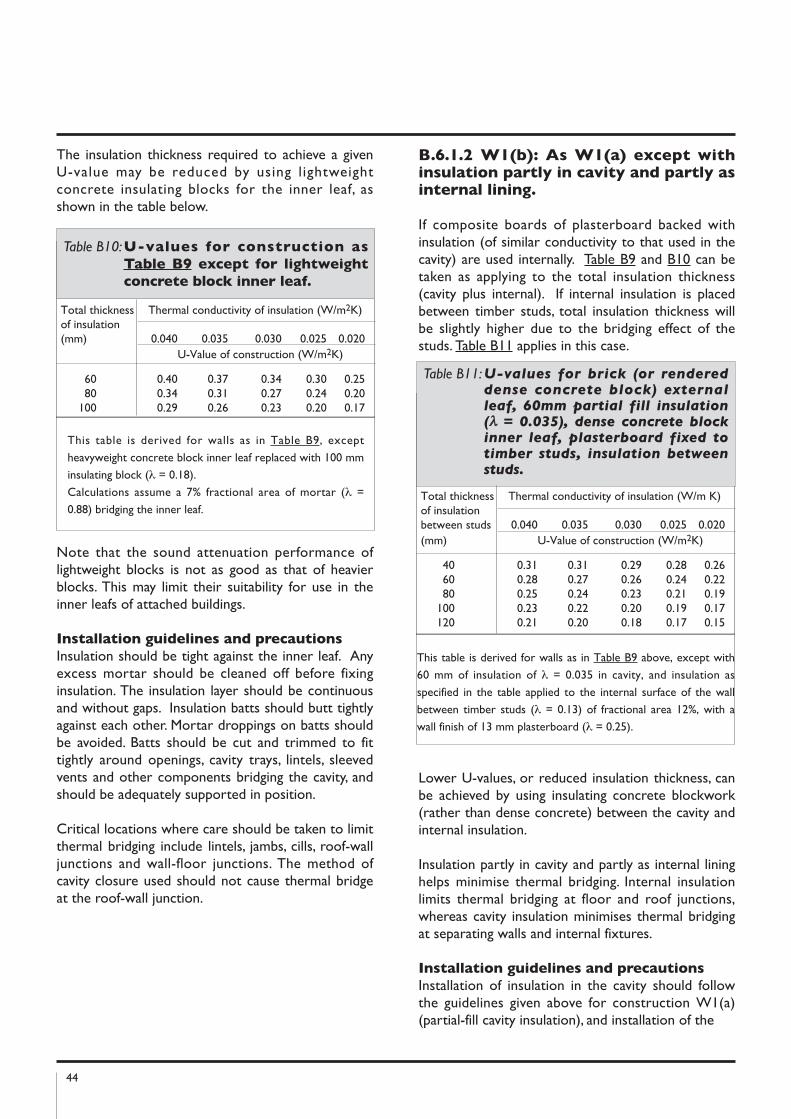
44
The insulation thickness required to achieve a givenU-value may be reduced by using lightweightconcrete insulating blocks for the inner leaf, asshown in the table below.
Note that the sound attenuation performance oflightweight blocks is not as good as that of heavierblocks. This may limit their suitability for use in theinner leafs of attached buildings.
Installation guidelines and precautions
Insulation should be tight against the inner leaf. Anyexcess mortar should be cleaned off before fixinginsulation. The insulation layer should be continuousand without gaps. Insulation batts should butt tightlyagainst each other. Mortar droppings on batts shouldbe avoided. Batts should be cut and trimmed to fittightly around openings, cavity trays, lintels, sleevedvents and other components bridging the cavity, andshould be adequately supported in position.
Critical locations where care should be taken to limitthermal bridging include lintels, jambs, cills, roof-walljunctions and wall-floor junctions. The method ofcavity closure used should not cause thermal bridgeat the roof-wall junction.
B.6.1.2 W1(b): As W1(a) except withinsulation partly in cavity and partly asinternal lining.
If composite boards of plasterboard backed withinsulation (of similar conductivity to that used in thecavity) are used internally. Table B9 and B10 can betaken as applying to the total insulation thickness(cavity plus internal). If internal insulation is placedbetween timber studs, total insulation thickness willbe slightly higher due to the bridging effect of thestuds. Table B11 applies in this case.
Lower U-values, or reduced insulation thickness, canbe achieved by using insulating concrete blockwork(rather than dense concrete) between the cavity andinternal insulation.
Insulation partly in cavity and partly as internal lininghelps minimise thermal bridging. Internal insulationlimits thermal bridging at floor and roof junctions,whereas cavity insulation minimises thermal bridgingat separating walls and internal fixtures.
Installation guidelines and precautions
Installation of insulation in the cavity should followthe guidelines given above for construction W1(a)(partial-fill cavity insulation), and installation of the
Total thickness Thermal conductivity of insulation (W/m2K)of insulation(mm) 0.040 0.035 0.030 0.025 0.020
U-Value of construction (W/m2K)
60 0.40 0.37 0.34 0.30 0.2580 0.34 0.31 0.27 0.24 0.20
100 0.29 0.26 0.23 0.20 0.17
Table B10:U-values for construction as
Table B9 except for lightweight
concrete block inner leaf.
This table is derived for walls as in Table B9, except
heavyweight concrete block inner leaf replaced with 100 mm
insulating block (λ = 0.18).
Calculations assume a 7% fractional area of mortar (λ =
0.88) bridging the inner leaf.Total thickness Thermal conductivity of insulation (W/m K)of insulationbetween studs 0.040 0.035 0.030 0.025 0.020(mm) U-Value of construction (W/m2K)
40 0.31 0.31 0.29 0.28 0.2660 0.28 0.27 0.26 0.24 0.2280 0.25 0.24 0.23 0.21 0.19
100 0.23 0.22 0.20 0.19 0.17120 0.21 0.20 0.18 0.17 0.15
Table B11:U-values for brick (or rendereddense concrete block) externalleaf, 60mm partial fill insulation(λ = 0.035), dense concrete blockinner leaf, plasterboard fixed totimber studs, insulation betweenstuds.
This table is derived for walls as in Table B9 above, except with
60 mm of insulation of λ = 0.035 in cavity, and insulation as
specified in the table applied to the internal surface of the wall
between timber studs (λ = 0.13) of fractional area 12%, with a
wall finish of 13 mm plasterboard (λ = 0.25).
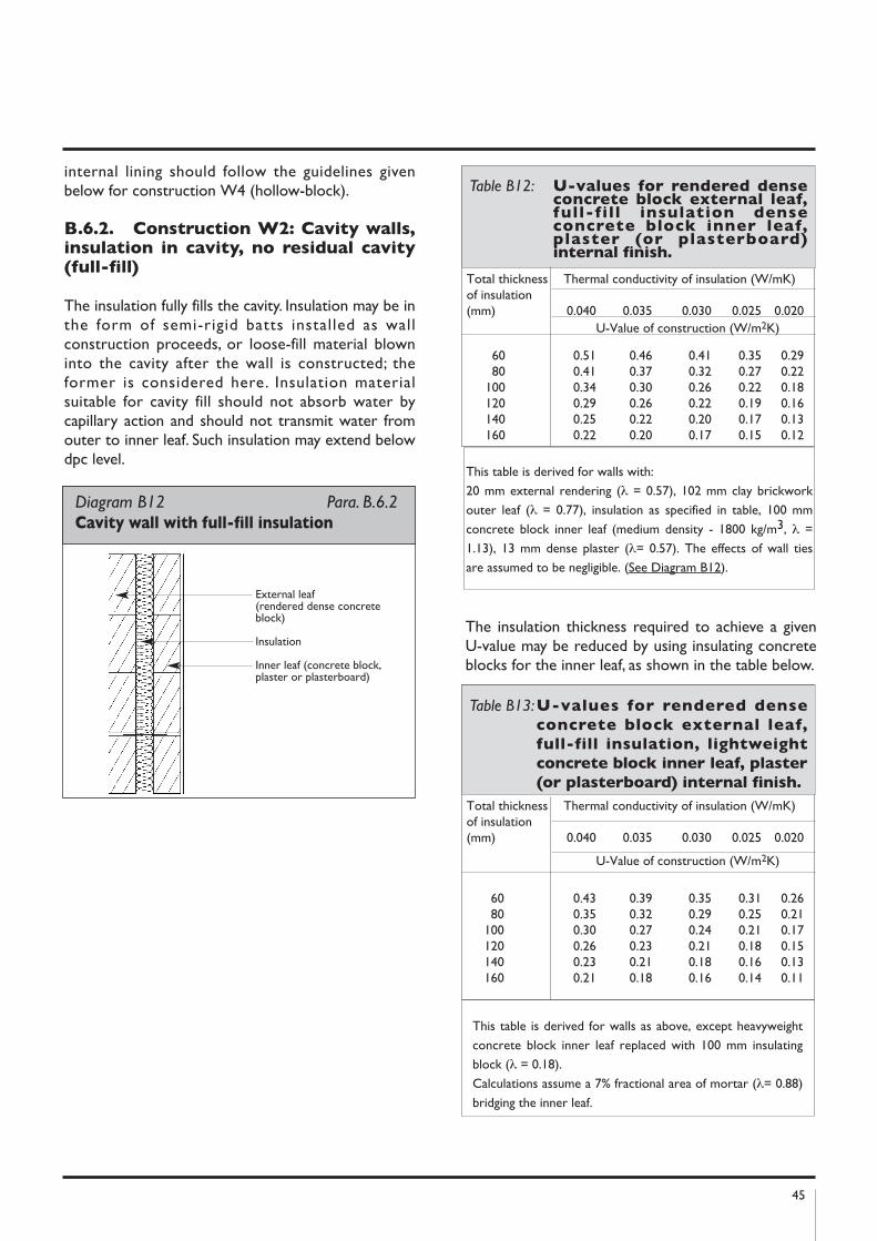
45
internal lining should follow the guidelines givenbelow for construction W4 (hollow-block).
B.6.2. Construction W2: Cavity walls,insulation in cavity, no residual cavity(full-fill)
The insulation fully fills the cavity. Insulation may be inthe form of semi-rigid batts installed as wallconstruction proceeds, or loose-fill material blowninto the cavity after the wall is constructed; theformer is considered here. Insulation materialsuitable for cavity fill should not absorb water bycapillary action and should not transmit water fromouter to inner leaf. Such insulation may extend belowdpc level.
The insulation thickness required to achieve a givenU-value may be reduced by using insulating concreteblocks for the inner leaf, as shown in the table below.
Diagram B12 Para. B.6.2 Cavity wall with full-fill insulation
External leaf (rendered dense concreteblock)
Insulation
Inner leaf (concrete block,plaster or plasterboard)
Total thickness Thermal conductivity of insulation (W/mK)of insulation(mm) 0.040 0.035 0.030 0.025 0.020
U-Value of construction (W/m2K)
60 0.51 0.46 0.41 0.35 0.2980 0.41 0.37 0.32 0.27 0.22
100 0.34 0.30 0.26 0.22 0.18120 0.29 0.26 0.22 0.19 0.16140 0.25 0.22 0.20 0.17 0.13160 0.22 0.20 0.17 0.15 0.12
Table B12: U-values for rendered denseconcrete block external leaf,full-fill insulation denseconcrete block inner leaf,plaster (or plasterboard)internal finish.
This table is derived for walls with:
20 mm external rendering (λ = 0.57), 102 mm clay brickwork
outer leaf (λ = 0.77), insulation as specified in table, 100 mm
concrete block inner leaf (medium density - 1800 kg/m3, λ =
1.13), 13 mm dense plaster (λ= 0.57). The effects of wall ties
are assumed to be negligible. (See Diagram B12).
Total thickness Thermal conductivity of insulation (W/mK)of insulation(mm) 0.040 0.035 0.030 0.025 0.020
U-Value of construction (W/m2K)
60 0.43 0.39 0.35 0.31 0.2680 0.35 0.32 0.29 0.25 0.21
100 0.30 0.27 0.24 0.21 0.17120 0.26 0.23 0.21 0.18 0.15140 0.23 0.21 0.18 0.16 0.13160 0.21 0.18 0.16 0.14 0.11
Table B13:U-values for rendered dense
concrete block external leaf,
full-fill insulation, lightweight
concrete block inner leaf, plaster
(or plasterboard) internal finish.
This table is derived for walls as above, except heavyweight
concrete block inner leaf replaced with 100 mm insulating
block (λ = 0.18).
Calculations assume a 7% fractional area of mortar (λ= 0.88)
bridging the inner leaf.
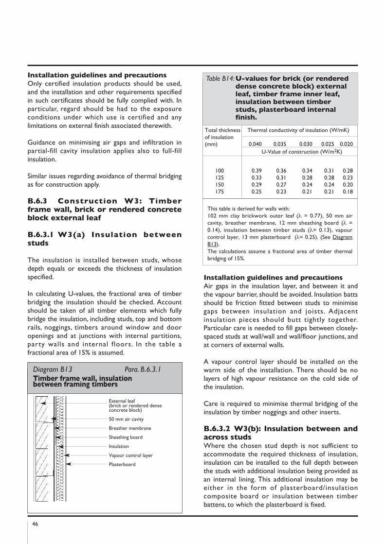
46
Installation guidelines and precautions
Only certified insulation products should be used,and the installation and other requirements specifiedin such certificates should be fully complied with. Inparticular, regard should be had to the exposureconditions under which use is certified and anylimitations on external finish associated therewith.
Guidance on minimising air gaps and infiltration inpartial-fill cavity insulation applies also to full-fillinsulation.
Similar issues regarding avoidance of thermal bridgingas for construction apply.
B.6.3 Construction W3: Timberframe wall, brick or rendered concreteblock external leaf
B.6.3.1 W3(a) Insulation betweenstuds
The insulation is installed between studs, whosedepth equals or exceeds the thickness of insulationspecified.
In calculating U-values, the fractional area of timberbridging the insulation should be checked. Accountshould be taken of all timber elements which fullybridge the insulation, including studs, top and bottomrails, noggings, timbers around window and dooropenings and at junctions with internal partitions,party walls and internal floors. In the table afractional area of 15% is assumed.
Installation guidelines and precautions
Air gaps in the insulation layer, and between it andthe vapour barrier, should be avoided. Insulation battsshould be friction fitted between studs to minimisegaps between insulation and joists. Adjacentinsulation pieces should butt tightly together.Particular care is needed to fill gaps between closely-spaced studs at wall/wall and wall/floor junctions, andat corners of external walls.
A vapour control layer should be installed on thewarm side of the installation. There should be nolayers of high vapour resistance on the cold side ofthe insulation.
Care is required to minimise thermal bridging of theinsulation by timber noggings and other inserts.
B.6.3.2 W3(b): Insulation between andacross studsWhere the chosen stud depth is not sufficient toaccommodate the required thickness of insulation,insulation can be installed to the full depth betweenthe studs with additional insulation being provided asan internal lining. This additional insulation may beeither in the form of plasterboard/insulationcomposite board or insulation between timberbattens, to which the plasterboard is fixed.
Total thickness Thermal conductivity of insulation (W/mK)of insulation(mm) 0.040 0.035 0.030 0.025 0.020
U-Value of construction (W/m2K)
100 0.39 0.36 0.34 0.31 0.28125 0.33 0.31 0.28 0.28 0.23150 0.29 0.27 0.24 0.24 0.20175 0.25 0.23 0.21 0.21 0.18
Table B14:U-values for brick (or rendereddense concrete block) externalleaf, timber frame inner leaf,insulation between timberstuds, plasterboard internalfinish.
This table is derived for walls with:102 mm clay brickwork outer leaf (λ = 0.77), 50 mm aircavity, breather membrane, 12 mm sheathing board (λ =0.14), insulation between timber studs (λ= 0.13), vapourcontrol layer, 13 mm plasterboard (λ= 0.25). (See DiagramB13).The calculations assume a fractional area of timber thermalbridging of 15%.
Diagram B13 Para. B.6.3.1Timber frame wall, insulation between framing timbers
External leaf (brick or rendered denseconcrete block)
50 mm air cavity
Breather membrane
Sheathing board
Insulation
Vapour control layer
Plasterboard

47
The vapour control layer should be on the warmside of the insulation. If different types of insulationare used between and inside the studs, the vapourresistance of the material between the studs shouldnot exceed that of the material across them.
B.6.4 Construction W4: hollowconcrete block wall, renderedexternally, internal insulation liningwith plasterboard finish.
The insulation is installed on the inner face of themasonry walls. It may be installed betweenpreservative-treated timber studs fixed to the wall,or in the form of composite boards of plaster backedwith insulation, or as a combination of these.
Installation guidelines and precautions
Air Movement
Air gaps in the insulation layer should be kept to aminimum. If using insulation between timber studs,there should be no gaps between insulation andstuds, between insulation and the vapour controllayer, between butt joints in the insulation, aroundservice penetrations, etc. If using composite boards,they should be tightly butted at edges, and shouldprovide complete and continuous coverage of theexternal wall.
When mounting composite boards on plaster dabsor timber battens, there is a danger that air will beable to circulate behind the insulation, reducing itseffectiveness. To minimise such air movement, the airgap behind the boards should be sealed along topand bottom, at corners and around window anddoor openings e.g. with continuous ribbon of plasteror timber studs.
Total thickness Thermal conductivity of insulation (W/m K)of insulationacross studs 0.040 0.035 0.030 0.025 0.020(mm) U-Value of construction (W/m2K)
20 0.32 0.32 0.31 0.29 0.2840 0.28 0.27 0.25 0.24 0.2260 0.24 0.23 0.22 0.20 0.1880 0.22 0.20 0.19 0.17 0.15
100 0.19 0.18 0.17 0.15 0.13
Table B15:U-values for brick (or rendered
dense concrete block) external
leaf, timber frame inner leaf,
insulation between 100 mm
timber studs, additional
insulation, plasterboard internal
finish.
This table is derived for walls as in W3(a) above, except with
100 mm of insulation of λ = 0.04 between 100 mm studs,
and an additional layer of insulation as specified in the table
across the studs.
Diagram B14 Para. B.6.4 hollow-block wall, internal insulation lining
Rendered hollow concreteblock
Insulation
Vapour control layer
Plasterboard
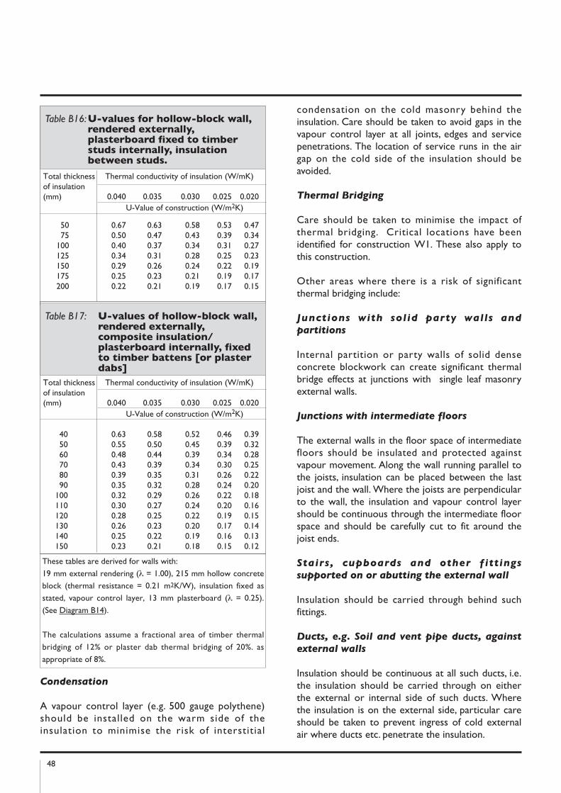
48
Condensation
A vapour control layer (e.g. 500 gauge polythene)should be installed on the warm side of theinsulation to minimise the risk of interstitial
condensation on the cold masonry behind theinsulation. Care should be taken to avoid gaps in thevapour control layer at all joints, edges and servicepenetrations. The location of service runs in the airgap on the cold side of the insulation should beavoided.
Thermal Bridging
Care should be taken to minimise the impact ofthermal bridging. Critical locations have beenidentified for construction W1. These also apply tothis construction.
Other areas where there is a risk of significantthermal bridging include:
Junctions with solid party walls and
partitions
Internal partition or party walls of solid denseconcrete blockwork can create significant thermalbridge effects at junctions with single leaf masonryexternal walls.
Junctions with intermediate floors
The external walls in the floor space of intermediatefloors should be insulated and protected againstvapour movement. Along the wall running parallel tothe joists, insulation can be placed between the lastjoist and the wall. Where the joists are perpendicularto the wall, the insulation and vapour control layershould be continuous through the intermediate floorspace and should be carefully cut to fit around thejoist ends.
Stairs, cupboards and other fittings
supported on or abutting the external wall
Insulation should be carried through behind suchfittings.
Ducts, e.g. Soil and vent pipe ducts, against
external walls
Insulation should be continuous at all such ducts, i.e.the insulation should be carried through on eitherthe external or internal side of such ducts. Wherethe insulation is on the external side, particular careshould be taken to prevent ingress of cold externalair where ducts etc. penetrate the insulation.
Total thickness Thermal conductivity of insulation (W/mK)of insulation(mm) 0.040 0.035 0.030 0.025 0.020
U-Value of construction (W/m2K)
50 0.67 0.63 0.58 0.53 0.4775 0.50 0.47 0.43 0.39 0.34
100 0.40 0.37 0.34 0.31 0.27125 0.34 0.31 0.28 0.25 0.23150 0.29 0.26 0.24 0.22 0.19175 0.25 0.23 0.21 0.19 0.17200 0.22 0.21 0.19 0.17 0.15
Table B16:U-values for hollow-block wall,rendered externally,plasterboard fixed to timberstuds internally, insulationbetween studs.
Total thickness Thermal conductivity of insulation (W/mK)of insulation(mm) 0.040 0.035 0.030 0.025 0.020
U-Value of construction (W/m2K)
40 0.63 0.58 0.52 0.46 0.3950 0.55 0.50 0.45 0.39 0.3260 0.48 0.44 0.39 0.34 0.2870 0.43 0.39 0.34 0.30 0.2580 0.39 0.35 0.31 0.26 0.2290 0.35 0.32 0.28 0.24 0.20
100 0.32 0.29 0.26 0.22 0.18110 0.30 0.27 0.24 0.20 0.16120 0.28 0.25 0.22 0.19 0.15130 0.26 0.23 0.20 0.17 0.14140 0.25 0.22 0.19 0.16 0.13150 0.23 0.21 0.18 0.15 0.12
Table B17: U-values of hollow-block wall,rendered externally,composite insulation/plasterboard internally, fixedto timber battens [or plasterdabs]
These tables are derived for walls with:
19 mm external rendering (λ = 1.00), 215 mm hollow concrete
block (thermal resistance = 0.21 m2K/W), insulation fixed as
stated, vapour control layer, 13 mm plasterboard (λ = 0.25).
(See Diagram B14).
The calculations assume a fractional area of timber thermal
bridging of 12% or plaster dab thermal bridging of 20%. as
appropriate of 8%.
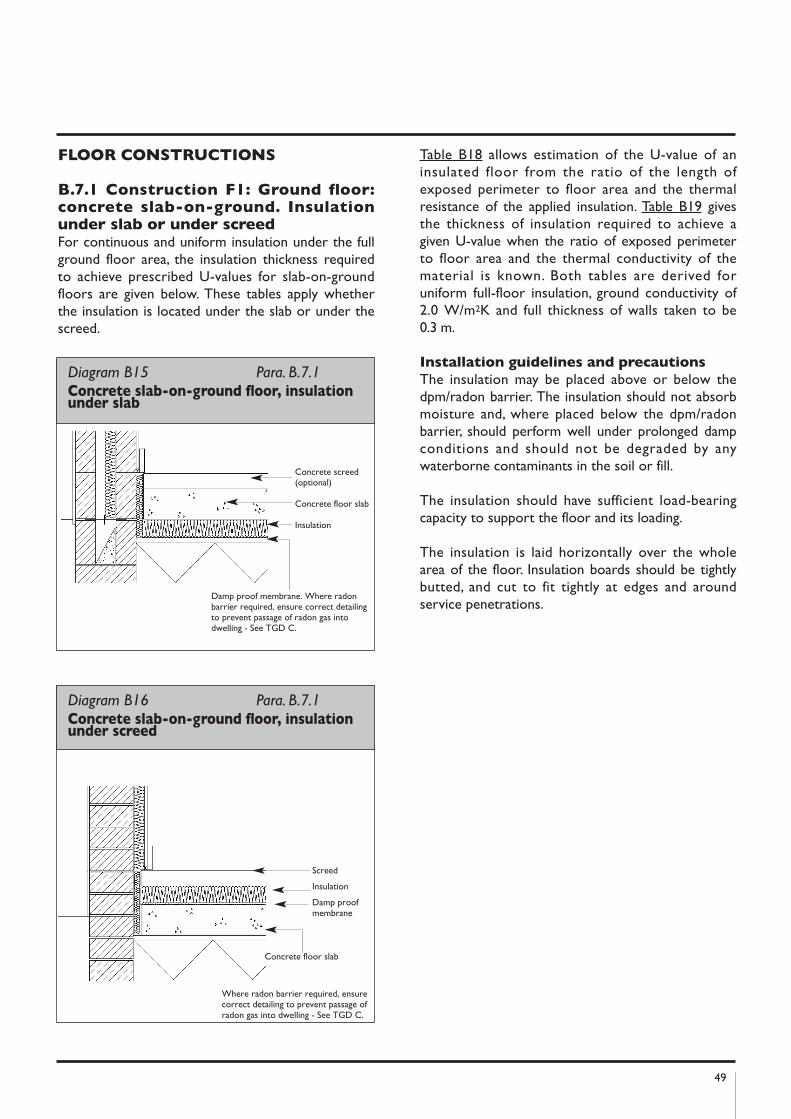
49
FLOOR COnSTRUCTIOnS
B.7.1 Construction F1: Ground floor:concrete slab-on-ground. Insulationunder slab or under screedFor continuous and uniform insulation under the fullground floor area, the insulation thickness requiredto achieve prescribed U-values for slab-on-groundfloors are given below. These tables apply whetherthe insulation is located under the slab or under thescreed.
Table B18 allows estimation of the U-value of aninsulated floor from the ratio of the length ofexposed perimeter to floor area and the thermalresistance of the applied insulation. Table B19 givesthe thickness of insulation required to achieve agiven U-value when the ratio of exposed perimeterto floor area and the thermal conductivity of thematerial is known. Both tables are derived foruniform full-floor insulation, ground conductivity of2.0 W/m2K and full thickness of walls taken to be0.3 m.
Installation guidelines and precautions
The insulation may be placed above or below thedpm/radon barrier. The insulation should not absorbmoisture and, where placed below the dpm/radonbarrier, should perform well under prolonged dampconditions and should not be degraded by anywaterborne contaminants in the soil or fill.
The insulation should have sufficient load-bearingcapacity to support the floor and its loading.
The insulation is laid horizontally over the wholearea of the floor. Insulation boards should be tightlybutted, and cut to fit tightly at edges and aroundservice penetrations.
Diagram B15 Para. B.7.1Concrete slab-on-ground floor, insulationunder slab
Damp proof membrane. Where radonbarrier required, ensure correct detailingto prevent passage of radon gas intodwelling - See TGD C.
Concrete screed(optional)
Concrete floor slab
Insulation
Diagram B16 Para. B.7.1 Concrete slab-on-ground floor, insulationunder screed
Screed
Insulation
Damp proofmembrane
Concrete floor slab
Where radon barrier required, ensurecorrect detailing to prevent passage ofradon gas into dwelling - See TGD C.
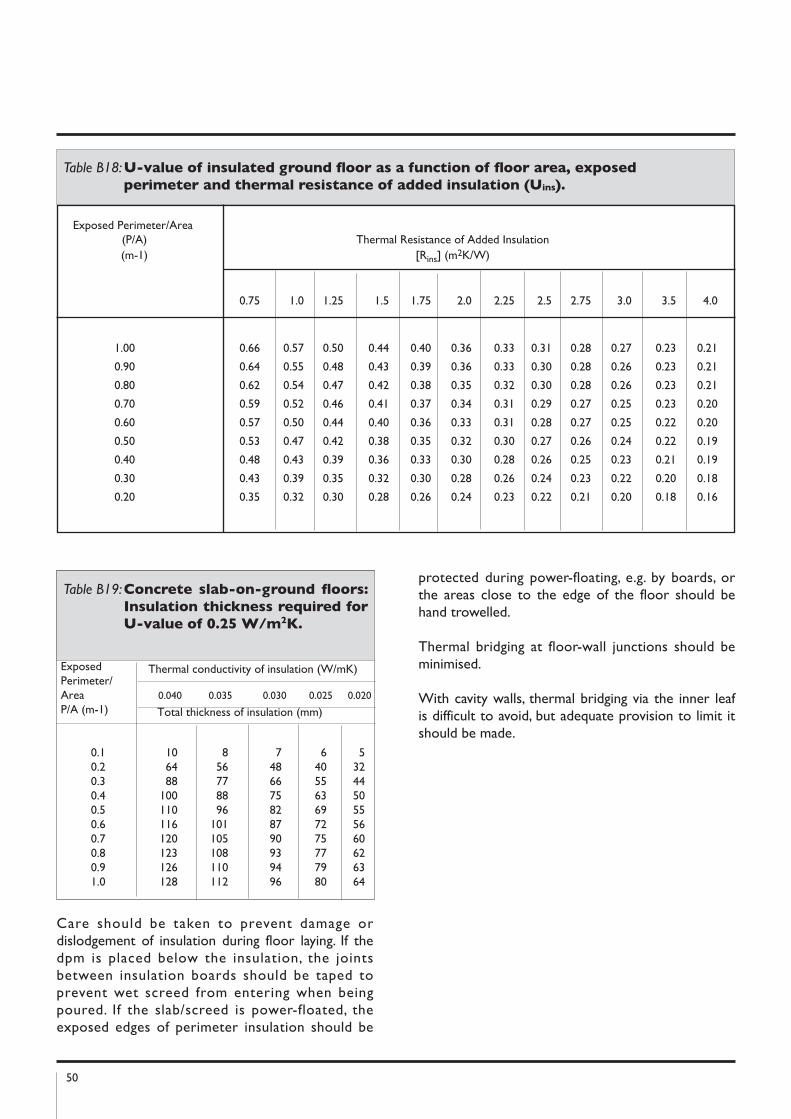
50
Care should be taken to prevent damage ordislodgement of insulation during floor laying. If thedpm is placed below the insulation, the jointsbetween insulation boards should be taped toprevent wet screed from entering when beingpoured. If the slab/screed is power-floated, theexposed edges of perimeter insulation should be
protected during power-floating, e.g. by boards, orthe areas close to the edge of the floor should behand trowelled.
Thermal bridging at floor-wall junctions should beminimised.
With cavity walls, thermal bridging via the inner leafis difficult to avoid, but adequate provision to limit itshould be made.
Exposed Thermal conductivity of insulation (W/mK)Perimeter/Area 0.040 0.035 0.030 0.025 0.020P/A (m-1) Total thickness of insulation (mm)
0.1 10 8 7 6 50.2 64 56 48 40 320.3 88 77 66 55 440.4 100 88 75 63 500.5 110 96 82 69 550.6 116 101 87 72 560.7 120 105 90 75 600.8 123 108 93 77 620.9 126 110 94 79 631.0 128 112 96 80 64
Table B19:Concrete slab-on-ground floors:
Insulation thickness required for
U-value of 0.25 W/m2k.
Table B18:U-value of insulated ground floor as a function of floor area, exposed
perimeter and thermal resistance of added insulation (Uins).
Exposed Perimeter/Area(P/A) Thermal Resistance of Added Insulation (m-1) [Rins] (m2K/W)
0.75 1.0 1.25 1.5 1.75 2.0 2.25 2.5 2.75 3.0 3.5 4.0
1.00 0.66 0.57 0.50 0.44 0.40 0.36 0.33 0.31 0.28 0.27 0.23 0.21
0.90 0.64 0.55 0.48 0.43 0.39 0.36 0.33 0.30 0.28 0.26 0.23 0.21
0.80 0.62 0.54 0.47 0.42 0.38 0.35 0.32 0.30 0.28 0.26 0.23 0.21
0.70 0.59 0.52 0.46 0.41 0.37 0.34 0.31 0.29 0.27 0.25 0.23 0.20
0.60 0.57 0.50 0.44 0.40 0.36 0.33 0.31 0.28 0.27 0.25 0.22 0.20
0.50 0.53 0.47 0.42 0.38 0.35 0.32 0.30 0.27 0.26 0.24 0.22 0.19
0.40 0.48 0.43 0.39 0.36 0.33 0.30 0.28 0.26 0.25 0.23 0.21 0.19
0.30 0.43 0.39 0.35 0.32 0.30 0.28 0.26 0.24 0.23 0.22 0.20 0.18
0.20 0.35 0.32 0.30 0.28 0.26 0.24 0.23 0.22 0.21 0.20 0.18 0.16
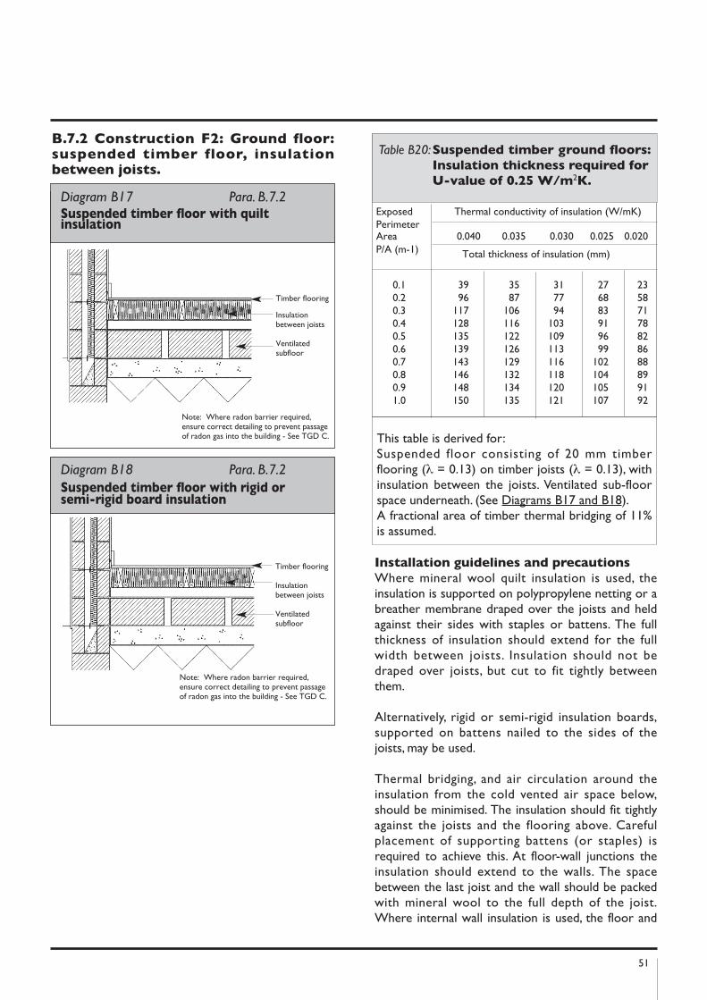
51
B.7.2 Construction F2: Ground floor:suspended timber floor, insulationbetween joists.
Installation guidelines and precautions
Where mineral wool quilt insulation is used, theinsulation is supported on polypropylene netting or abreather membrane draped over the joists and heldagainst their sides with staples or battens. The fullthickness of insulation should extend for the fullwidth between joists. Insulation should not bedraped over joists, but cut to fit tightly betweenthem.
Alternatively, rigid or semi-rigid insulation boards,supported on battens nailed to the sides of thejoists, may be used.
Thermal bridging, and air circulation around theinsulation from the cold vented air space below,should be minimised. The insulation should fit tightlyagainst the joists and the flooring above. Carefulplacement of supporting battens (or staples) isrequired to achieve this. At floor-wall junctions theinsulation should extend to the walls. The spacebetween the last joist and the wall should be packedwith mineral wool to the full depth of the joist.Where internal wall insulation is used, the floor and
Diagram B17 Para. B.7.2Suspended timber floor with quiltinsulation
Timber flooring
Insulationbetween joists
Ventilatedsubfloor
Note: Where radon barrier required,ensure correct detailing to prevent passageof radon gas into the building - See TGD C.
Diagram B18 Para. B.7.2
Suspended timber floor with rigid or semi-rigid board insulation
Timber flooring
Insulationbetween joists
Ventilatedsubfloor
Note: Where radon barrier required,ensure correct detailing to prevent passageof radon gas into the building - See TGD C.
Exposed Thermal conductivity of insulation (W/mK)PerimeterArea 0.040 0.035 0.030 0.025 0.020P/A (m-1) Total thickness of insulation (mm)
0.1 39 35 31 27 230.2 96 87 77 68 580.3 117 106 94 83 710.4 128 116 103 91 780.5 135 122 109 96 820.6 139 126 113 99 860.7 143 129 116 102 880.8 146 132 118 104 890.9 148 134 120 105 911.0 150 135 121 107 92
Table B20:Suspended timber ground floors:
Insulation thickness required for
U-value of 0.25 W/m2k.
This table is derived for:Suspended floor consisting of 20 mm timberflooring (λ = 0.13) on timber joists (λ = 0.13), withinsulation between the joists. Ventilated sub-floorspace underneath. (See Diagrams B17 and B18).A fractional area of timber thermal bridging of 11%is assumed.
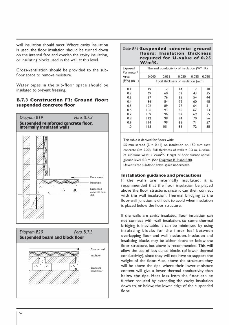
52
wall insulation should meet. Where cavity insulationis used, the floor insulation should be turned downon the internal face and overlap the cavity insulation,or insulating blocks used in the wall at this level.
Cross-ventilation should be provided to the sub-floor space to remove moisture.
Water pipes in the sub-floor space should beinsulated to prevent freezing.
B.7.3 Construction F3: Ground floor:suspended concrete floor
Installation guidance and precautions
If the walls are internally insulated, it isrecommended that the floor insulation be placedabove the floor structure, since it can then connectwith the wall insulation. Thermal bridging at thefloor-wall junction is difficult to avoid when insulationis placed below the floor structure.
If the walls are cavity insulated, floor insulation cannot connect with wall insulation, so some thermalbridging is inevitable. It can be minimised by usinginsulating blocks for the inner leaf betweenoverlapping floor and wall insulation. Insulation andinsulating blocks may be either above or below thefloor structure, but above is recommended. This willallow the use of less dense blocks (of lower thermalconductivity), since they will not have to support theweight of the floor. Also, above the structure theywill be above the dpc, where their lower moisturecontent will give a lower thermal conductivity thanbelow the dpc. Heat loss from the floor can befurther reduced by extending the cavity insulationdown to, or below, the lower edge of the suspendedfloor.
Exposed Thermal conductivity of insulation (W/mK)Perimeter/Area 0.040 0.035 0.030 0.025 0.020(P/A) (m-1) Total thickness of insulation (mm)
0.1 19 17 14 12 100.2 69 60 52 43 350.3 87 76 65 54 440.4 96 84 72 60 480.5 102 89 77 64 510.6 106 93 80 67 530.7 109 96 82 69 550.8 112 98 84 70 560.9 114 99 85 71 571.0 115 101 86 72 58
Table B21:Suspended concrete groundfloors: Insulation thicknessrequired for U-value of 0.25W/m2k.
Diagram B19 Para. B.7.3
Suspended reinforced concrete floor,internally insulated walls
Floor screed
Insulation
Suspendedconcrete floorslab
Diagram B20 Para. B.7.3 Suspended beam and block floor
Floor screed
Insulation
Beam andblock floor
This table is derived for floors with:
65 mm screed (λ = 0.41) on insulation on 150 mm cast
concrete (λ= 2.20). Full thickness of walls = 0.3 m, U-value
of sub-floor walls: 2 W/m2K. Height of floor surface above
ground level: 0.3 m. (See Diagrams B19 and B20).
Unventilated sub-floor crawl space underneath.
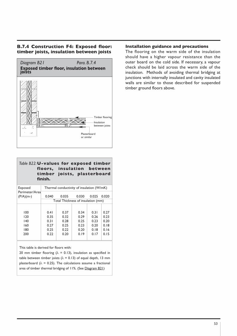
53
B.7.4 Construction F4: Exposed floor:timber joists, insulation between joists
Installation guidance and precautions
The flooring on the warm side of the insulationshould have a higher vapour resistance than theouter board on the cold side. If necessary, a vapourcheck should be laid across the warm side of theinsulation. Methods of avoiding thermal bridging atjunctions with internally insulated and cavity insulatedwalls are similar to those described for suspendedtimber ground floors above.
Diagram B21 Para. B.7.4Exposed timber floor, insulation betweenjoists
Timber flooring
Insulationbetween joists
Plasterboardor similar
Exposed Thermal conductivity of insulation (W/mK)Perimeter/Area(P/A)(m-) 0.040 0.035 0.030 0.025 0.020
Total Thickness of insulation (mm)
100 0.41 0.37 0.34 0.31 0.27120 0.35 0.32 0.29 0.26 0.23140 0.31 0.28 0.25 0.23 0.20160 0.27 0.25 0.23 0.20 0.18180 0.25 0.22 0.20 0.18 0.16200 0.22 0.20 0.19 0.17 0.15
Table B22:U-values for exposed timber
floors, insulation between
timber joists, plasterboard
finish.
This table is derived for floors with:
20 mm timber flooring (λ = 0.13), insulation as specified in
table between timber joists (λ = 0.13) of equal depth, 13 mm
plasterboard (λ = 0.25). The calculations assume a fractional
area of timber thermal bridging of 11%. (See Diagram B21)
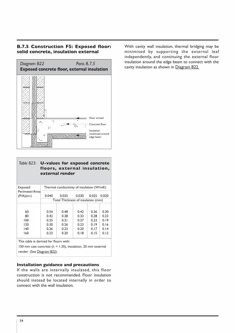
54
B.7.5 Construction F5: Exposed floor:solid concrete, insulation external
Installation guidance and precautions
If the walls are internally insulated, this floorconstruction is not recommended. Floor insulationshould instead be located internally in order toconnect with the wall insulation.
With cavity wall insulation, thermal bridging may beminimised by supporting the external leafindependently, and continuing the external floorinsulation around the edge beam to connect with thecavity insulation as shown in Diagram B22.
Exposed Thermal conductivity of insulation (W/mK)Perimeter/Area(P/A)(m-) 0.040 0.035 0.030 0.025 0.020
Total Thickness of insulation (mm)
60 0.54 0.48 0.42 0.36 0.3080 0.42 0.38 0.33 0.28 0.23
100 0.35 0.31 0.27 0.23 0.19120 0.30 0.26 0.23 0.19 0.16140 0.26 0.23 0.20 0.17 0.14160 0.23 0.20 0.18 0.15 0.12
Table B23: U-values for exposed concrete
floors, external insulation,
external render
This table is derived for floors with:
150 mm cast concrete (λ = 1.35), insulation, 20 mm external
render. (See Diagram B22).
Diagram B22 Para. B.7.5Exposed concrete floor, external insulation
Floor screed
Concrete floor
Insulationcontinued aroundedge beam
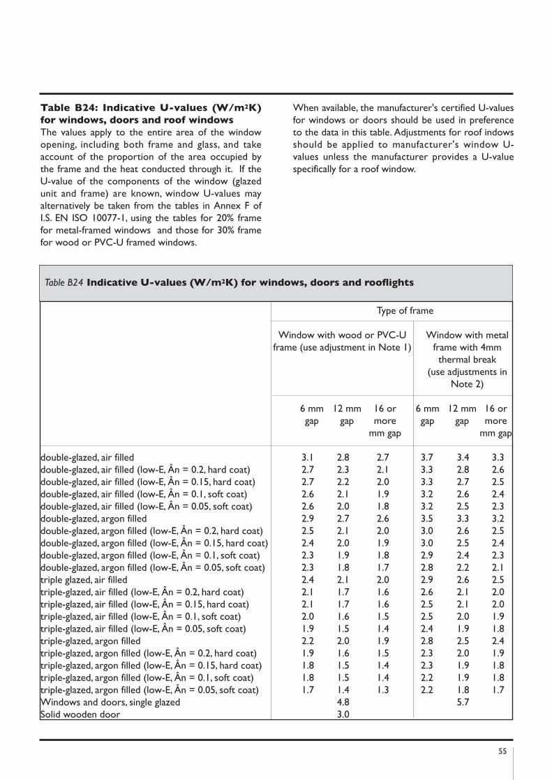
55
Table B24: Indicative U-values (W/m2k)
for windows, doors and roof windows
The values apply to the entire area of the windowopening, including both frame and glass, and takeaccount of the proportion of the area occupied bythe frame and the heat conducted through it. If theU-value of the components of the window (glazedunit and frame) are known, window U-values mayalternatively be taken from the tables in Annex F ofI.S. EN ISO 10077-1, using the tables for 20% framefor metal-framed windows and those for 30% framefor wood or PVC-U framed windows.
When available, the manufacturer's certified U-valuesfor windows or doors should be used in preferenceto the data in this table. Adjustments for roof indowsshould be applied to manufacturer's window U-values unless the manufacturer provides a U-valuespecifically for a roof window.
Table B24 Indicative U-values (W/m2k) for windows, doors and rooflights
Type of frame
Window with wood or PVC-U Window with metal frame (use adjustment in Note 1) frame with 4mm
thermal break(use adjustments in
Note 2)
6 mm 12 mm 16 or 6 mm 12 mm 16 or gap gap more gap gap more
mm gap mm gap
double-glazed, air filled 3.1 2.8 2.7 3.7 3.4 3.3double-glazed, air filled (low-E, Ân = 0.2, hard coat) 2.7 2.3 2.1 3.3 2.8 2.6double-glazed, air filled (low-E, Ân = 0.15, hard coat) 2.7 2.2 2.0 3.3 2.7 2.5double-glazed, air filled (low-E, Ân = 0.1, soft coat) 2.6 2.1 1.9 3.2 2.6 2.4double-glazed, air filled (low-E, Ân = 0.05, soft coat) 2.6 2.0 1.8 3.2 2.5 2.3double-glazed, argon filled 2.9 2.7 2.6 3.5 3.3 3.2double-glazed, argon filled (low-E, Ân = 0.2, hard coat) 2.5 2.1 2.0 3.0 2.6 2.5double-glazed, argon filled (low-E, Ân = 0.15, hard coat) 2.4 2.0 1.9 3.0 2.5 2.4double-glazed, argon filled (low-E, Ân = 0.1, soft coat) 2.3 1.9 1.8 2.9 2.4 2.3double-glazed, argon filled (low-E, Ân = 0.05, soft coat) 2.3 1.8 1.7 2.8 2.2 2.1triple glazed, air filled 2.4 2.1 2.0 2.9 2.6 2.5triple-glazed, air filled (low-E, Ân = 0.2, hard coat) 2.1 1.7 1.6 2.6 2.1 2.0triple-glazed, air filled (low-E, Ân = 0.15, hard coat) 2.1 1.7 1.6 2.5 2.1 2.0triple-glazed, air filled (low-E, Ân = 0.1, soft coat) 2.0 1.6 1.5 2.5 2.0 1.9triple-glazed, air filled (low-E, Ân = 0.05, soft coat) 1.9 1.5 1.4 2.4 1.9 1.8triple-glazed, argon filled 2.2 2.0 1.9 2.8 2.5 2.4triple-glazed, argon filled (low-E, Ân = 0.2, hard coat) 1.9 1.6 1.5 2.3 2.0 1.9triple-glazed, argon filled (low-E, Ân = 0.15, hard coat) 1.8 1.5 1.4 2.3 1.9 1.8triple-glazed, argon filled (low-E, Ân = 0.1, soft coat) 1.8 1.5 1.4 2.2 1.9 1.8triple-glazed, argon filled (low-E, Ân = 0.05, soft coat) 1.7 1.4 1.3 2.2 1.8 1.7Windows and doors, single glazed 4.8 5.7Solid wooden door 3.0
56
notes:
(1) For roof windows with wooden or PVC-U frames apply the following adjustments to U-values:____________________________________________________________________________________Wood or PVC-U frame U-value adjustment for roof window, W/m2k
____________________________________________________________________________________________
Single glazed +0.3Double glazed +0.2Triple glazed +0.2____________________________________________________________________________________
(2) For windows or roof windows with metal frames apply the following adjustments to U-values:____________________________________________________________________________________
Metal frames Adjustment to U-value, W/m2k
Window Roof window
____________________________________________________________________________________
Metal, no thermal break +0.3 +0.7Metal, thermal break 4 mm 0 +0.3Metal, thermal break 8 mm -0.1 +0.2Metal, thermal break 12 mm -0.2 +0.1Metal, thermal break 20 mm -0.3 0Metal, thermal break 32 mm -0.4 -0.1
(3) For doors which are half-glazed (approximately) the U-value of the door is the average of the appropriatewindow U-value and that of the non-glazed part of the door (e.g. solid wooden door [Uvalue of 3.0W/m2K] half-glazed with double glazing [low-E, hard coat, argon filled, 6 mm gap, Uvalue of 2.5 W/m2K] hasa resultant U-value of 0.5(3.0+2.5) = 2.75 W/m2K).
Source: DEAP Manual Version 2.1 January 2007
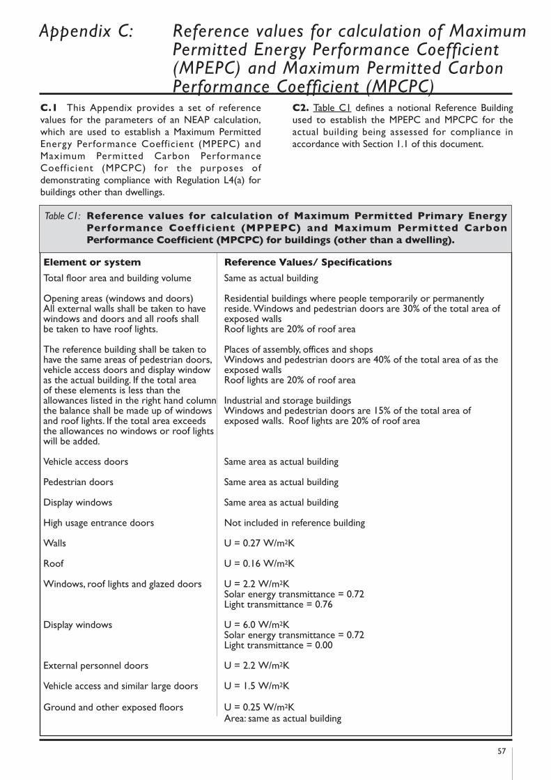
57
C.1 This Appendix provides a set of referencevalues for the parameters of an NEAP calculation,which are used to establish a Maximum PermittedEnergy Performance Coefficient (MPEPC) andMaximum Permitted Carbon PerformanceCoefficient (MPCPC) for the purposes ofdemonstrating compliance with Regulation L4(a) forbuildings other than dwellings.
C2. Table C1 defines a notional Reference Buildingused to establish the MPEPC and MPCPC for theactual building being assessed for compliance inaccordance with Section 1.1 of this document.
Appendix C: Reference values for calculation of Maximum Permitted Energy Performance Coefficient (MPEPC) and Maximum Permitted Carbon Performance Coefficient (MPCPC)
Element or system Reference Values/ Specifications
Total floor area and building volume Same as actual building
Opening areas (windows and doors) Residential buildings where people temporarily or permanentlyAll external walls shall be taken to have reside. Windows and pedestrian doors are 30% of the total area of windows and doors and all roofs shall exposed wallsbe taken to have roof lights. Roof lights are 20% of roof area
The reference building shall be taken to Places of assembly, offices and shopshave the same areas of pedestrian doors, Windows and pedestrian doors are 40% of the total area of as thevehicle access doors and display window exposed wallsas the actual building. If the total area Roof lights are 20% of roof areaof these elements is less than the allowances listed in the right hand column Industrial and storage buildings the balance shall be made up of windows Windows and pedestrian doors are 15% of the total area ofand roof lights. If the total area exceeds exposed walls. Roof lights are 20% of roof areathe allowances no windows or roof lightswill be added.
Vehicle access doors Same area as actual building
Pedestrian doors Same area as actual building
Display windows Same area as actual building
High usage entrance doors Not included in reference building
Walls U = 0.27 W/m2K
Roof U = 0.16 W/m2K
Windows, roof lights and glazed doors U = 2.2 W/m2KSolar energy transmittance = 0.72Light transmittance = 0.76
Display windows U = 6.0 W/m2KSolar energy transmittance = 0.72Light transmittance = 0.00
External personnel doors U = 2.2 W/m2K
Vehicle access and similar large doors U = 1.5 W/m2K
Ground and other exposed floors U = 0.25 W/m2KArea: same as actual building
Table C1: Reference values for calculation of Maximum Permitted Primary Energy
Performance Coefficient (MPPEPC) and Maximum Permitted Carbon
Performance Coefficient (MPCPC) for buildings (other than a dwelling).
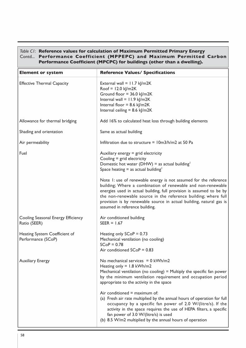
58
Element or system Reference Values/ Specifications
Effective Thermal Capacity External wall = 11.7 kJ/m2KRoof = 12.0 kJ/m2KGround floor = 36.0 kJ/m2KInternal wall = 11.9 kJ/m2KInternal floor = 8.6 kJ/m2KInternal ceiling = 8.6 kJ/m2K
Allowance for thermal bridging Add 16% to calculated heat loss through building elements
Shading and orientation Same as actual building
Air permeability Infiltration due to structure = 10m3/h/m2 at 50 Pa
Fuel Auxiliary energy = grid electricityCooling = grid electricityDomestic hot water (DHW) = as actual building1
Space heating = as actual building1
Note 1: use of renewable energy is not assumed for the referencebuilding; Where a combination of renewable and non-renewableenergies used in actual building, full provision is assumed to be bythe non-renewable source in the reference building; where fullprovision is by renewable source in actual building, natural gas isassumed in reference building.
Cooling Seasonal Energy Efficiency Air conditioned buildingRatio (SEER) SEER = 1.67
Heating System Coefficient of Heating only SCoP = 0.73Performance (SCoP) Mechanical ventilation (no cooling)
SCoP = 0.78Air conditioned SCoP = 0.83
Auxiliary Energy No mechanical services = 0 kWh/m2Heating only = 1.8 kWh/m2Mechanical ventilation (no cooling) = Multiply the specific fan powerby the minimum ventilation requirement and occupation periodappropriate to the activity in the space
Air conditioned = maximum of:(a) Fresh air rate multiplied by the annual hours of operation for full
occupancy by a specific fan power of 2.0 W/(litre/s). If theactivity in the space requires the use of HEPA filters, a specificfan power of 3.0 W/(litre/s) is used
(b) 8.5 W/m2 multiplied by the annual hours of operation
Table C1: Reference values for calculation of Maximum Permitted Primary Energy
Contd... Performance Coefficient (MPPEPC) and Maximum Permitted Carbon
Performance Coefficient (MPCPC) for buildings (other than a dwelling).
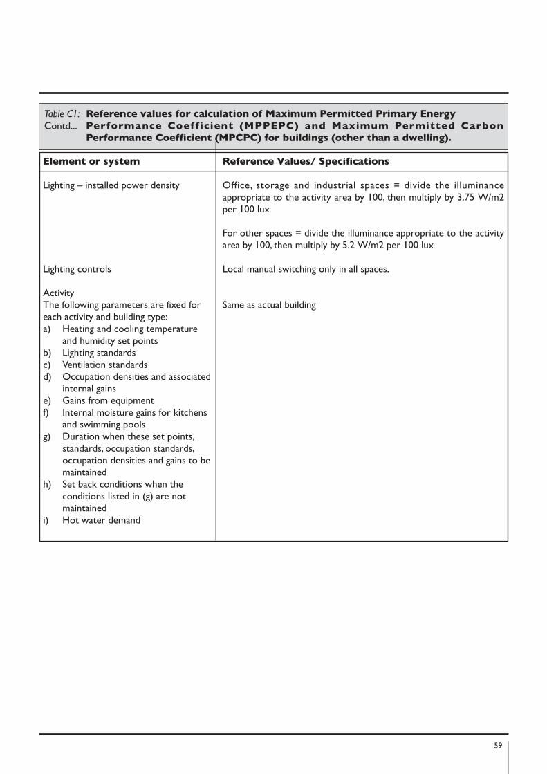
59
Element or system Reference Values/ Specifications
Lighting – installed power density Office, storage and industrial spaces = divide the illuminanceappropriate to the activity area by 100, then multiply by 3.75 W/m2per 100 lux
For other spaces = divide the illuminance appropriate to the activityarea by 100, then multiply by 5.2 W/m2 per 100 lux
Lighting controls Local manual switching only in all spaces.
ActivityThe following parameters are fixed for Same as actual buildingeach activity and building type:a) Heating and cooling temperature
and humidity set pointsb) Lighting standardsc) Ventilation standardsd) Occupation densities and associated
internal gainse) Gains from equipmentf) Internal moisture gains for kitchens
and swimming poolsg) Duration when these set points,
standards, occupation standards, occupation densities and gains to be maintained
h) Set back conditions when the conditions listed in (g) are not maintained
i) Hot water demand
Table C1: Reference values for calculation of Maximum Permitted Primary Energy
Contd... Performance Coefficient (MPPEPC) and Maximum Permitted Carbon
Performance Coefficient (MPCPC) for buildings (other than a dwelling).
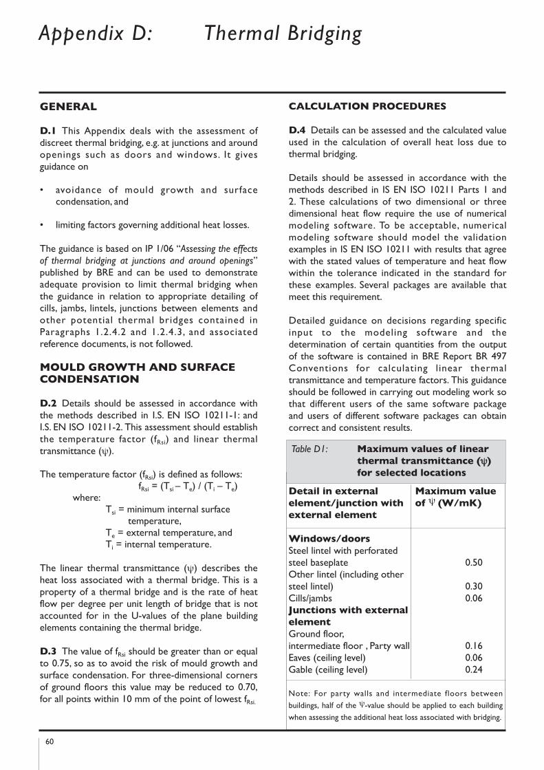
GEnERAL
D.1 This Appendix deals with the assessment ofdiscreet thermal bridging, e.g. at junctions and aroundopenings such as doors and windows. It givesguidance on
• avoidance of mould growth and surfacecondensation, and
• limiting factors governing additional heat losses.
The guidance is based on IP 1/06 “Assessing the effects
of thermal bridging at junctions and around openings”published by BRE and can be used to demonstrateadequate provision to limit thermal bridging whenthe guidance in relation to appropriate detailing ofcills, jambs, lintels, junctions between elements andother potential thermal bridges contained inParagraphs 1.2.4.2 and 1.2.4.3, and associatedreference documents, is not followed.
MOULD GROWTh AnD SURFACECOnDEnSATIOn
D.2 Details should be assessed in accordance withthe methods described in I.S. EN ISO 10211-1: andI.S. EN ISO 10211-2. This assessment should establishthe temperature factor (fRsi) and linear thermaltransmittance (ψ).
The temperature factor (fRsi) is defined as follows:fRsi = (Tsi – Te) / (Ti – Te)
where:Tsi = minimum internal surface
temperature,Te = external temperature, andTi = internal temperature.
The linear thermal transmittance (ψ) describes theheat loss associated with a thermal bridge. This is aproperty of a thermal bridge and is the rate of heatflow per degree per unit length of bridge that is notaccounted for in the U-values of the plane buildingelements containing the thermal bridge.
D.3 The value of fRsi should be greater than or equalto 0.75, so as to avoid the risk of mould growth andsurface condensation. For three-dimensional cornersof ground floors this value may be reduced to 0.70,for all points within 10 mm of the point of lowest fRsi.
CALCULATIOn PROCEDURES
D.4 Details can be assessed and the calculated valueused in the calculation of overall heat loss due tothermal bridging.
Details should be assessed in accordance with themethods described in IS EN ISO 10211 Parts 1 and2. These calculations of two dimensional or threedimensional heat flow require the use of numericalmodeling software. To be acceptable, numericalmodeling software should model the validationexamples in IS EN ISO 10211 with results that agreewith the stated values of temperature and heat flowwithin the tolerance indicated in the standard forthese examples. Several packages are available thatmeet this requirement.
Detailed guidance on decisions regarding specificinput to the modeling software and thedetermination of certain quantities from the outputof the software is contained in BRE Report BR 497Conventions for calculating linear thermaltransmittance and temperature factors. This guidanceshould be followed in carrying out modeling work sothat different users of the same software packageand users of different software packages can obtaincorrect and consistent results.
60
Detail in external Maximum value
element/junction with of ψ (W/mk)
external element
Windows/doors
Steel lintel with perforatedsteel baseplate 0.50Other lintel (including othersteel lintel) 0.30Cills/jambs 0.06junctions with external
element
Ground floor, intermediate floor , Party wall 0.16Eaves (ceiling level) 0.06Gable (ceiling level) 0.24
Note: For party walls and intermediate floors between
buildings, half of the ψ-value should be applied to each building
when assessing the additional heat loss associated with bridging.
Table D1: Maximum values of linear
thermal transmittance (ψ)
for selected locations
Appendix D: Thermal Bridging
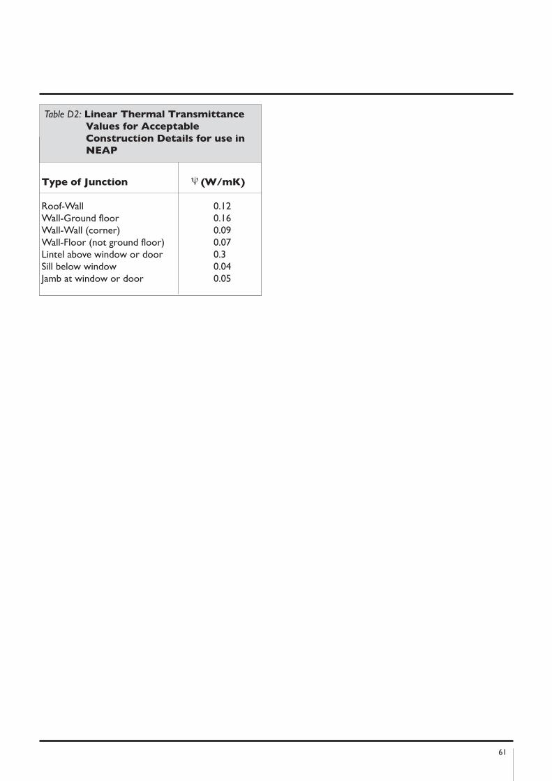
61
Type of junction ψ (W/mk)
Roof-Wall 0.12Wall-Ground floor 0.16Wall-Wall (corner) 0.09Wall-Floor (not ground floor) 0.07Lintel above window or door 0.3Sill below window 0.04Jamb at window or door 0.05
Table D2: Linear Thermal Transmittance
Values for Acceptable
Construction Details for use in
nEAP
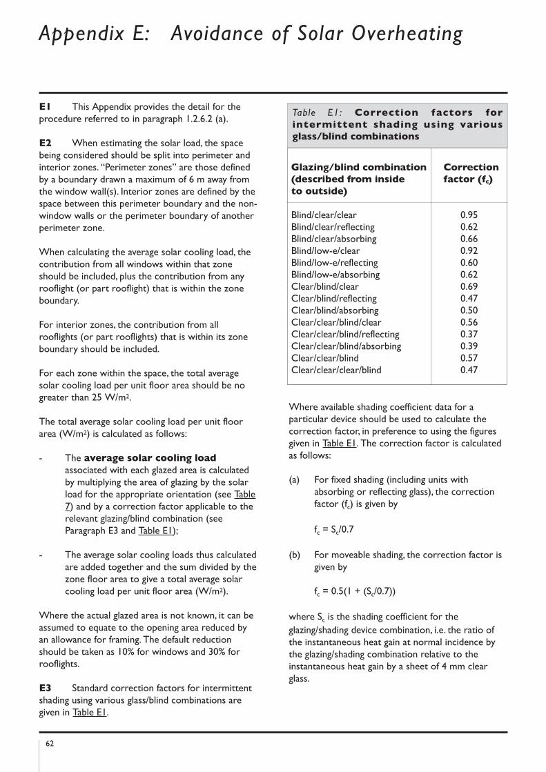
62
Appendix E: Avoidance of Solar Overheating
E1 This Appendix provides the detail for theprocedure referred to in paragraph 1.2.6.2 (a).
E2 When estimating the solar load, the spacebeing considered should be split into perimeter andinterior zones. “Perimeter zones” are those definedby a boundary drawn a maximum of 6 m away fromthe window wall(s). Interior zones are defined by thespace between this perimeter boundary and the non-window walls or the perimeter boundary of anotherperimeter zone.
When calculating the average solar cooling load, thecontribution from all windows within that zoneshould be included, plus the contribution from anyrooflight (or part rooflight) that is within the zoneboundary.
For interior zones, the contribution from allrooflights (or part rooflights) that is within its zoneboundary should be included.
For each zone within the space, the total averagesolar cooling load per unit floor area should be nogreater than 25 W/m2.
The total average solar cooling load per unit floorarea (W/m2) is calculated as follows:
- The average solar cooling load
associated with each glazed area is calculatedby multiplying the area of glazing by the solarload for the appropriate orientation (see Table7) and by a correction factor applicable to therelevant glazing/blind combination (seeParagraph E3 and Table E1);
- The average solar cooling loads thus calculatedare added together and the sum divided by thezone floor area to give a total average solarcooling load per unit floor area (W/m2).
Where the actual glazed area is not known, it can beassumed to equate to the opening area reduced byan allowance for framing. The default reductionshould be taken as 10% for windows and 30% forrooflights.
E3 Standard correction factors for intermittentshading using various glass/blind combinations aregiven in Table E1.
Where available shading coefficient data for aparticular device should be used to calculate thecorrection factor, in preference to using the figuresgiven in Table E1. The correction factor is calculatedas follows:
(a) For fixed shading (including units withabsorbing or reflecting glass), the correctionfactor (fc) is given by
fc = Sc/0.7
(b) For moveable shading, the correction factor isgiven by
fc = 0.5(1 + (Sc/0.7))
where Sc is the shading coefficient for theglazing/shading device combination, i.e. the ratio ofthe instantaneous heat gain at normal incidence bythe glazing/shading combination relative to theinstantaneous heat gain by a sheet of 4 mm clearglass.
Glazing/blind combination Correction
(described from inside factor (fc)
to outside)
Blind/clear/clear 0.95Blind/clear/reflecting 0.62Blind/clear/absorbing 0.66Blind/low-e/clear 0.92Blind/low-e/reflecting 0.60Blind/low-e/absorbing 0.62Clear/blind/clear 0.69Clear/blind/reflecting 0.47Clear/blind/absorbing 0.50Clear/clear/blind/clear 0.56Clear/clear/blind/reflecting 0.37Clear/clear/blind/absorbing 0.39Clear/clear/blind 0.57Clear/clear/clear/blind 0.47
Table E1: Correction factors for
intermittent shading using various
glass/blind combinations
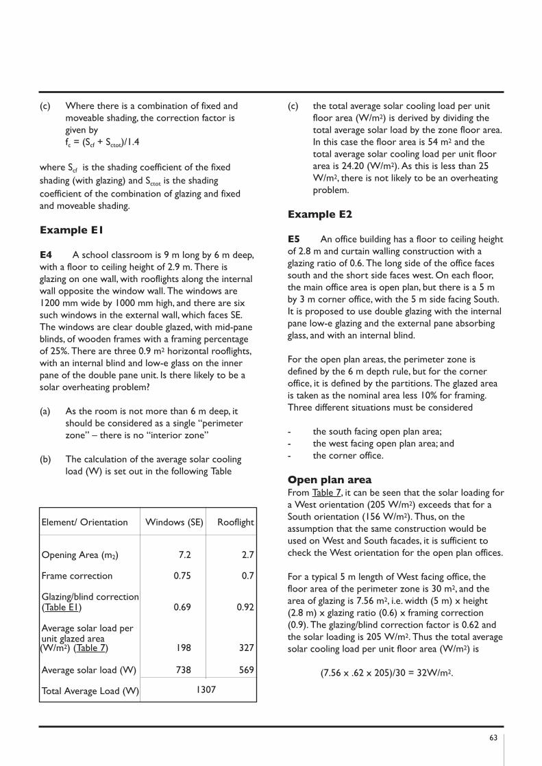
63
(c) Where there is a combination of fixed andmoveable shading, the correction factor isgiven byfc = (Scf + Sctot)/1.4
where Scf is the shading coefficient of the fixedshading (with glazing) and Sctot is the shadingcoefficient of the combination of glazing and fixedand moveable shading.
Example E1
E4 A school classroom is 9 m long by 6 m deep,with a floor to ceiling height of 2.9 m. There isglazing on one wall, with rooflights along the internalwall opposite the window wall. The windows are1200 mm wide by 1000 mm high, and there are sixsuch windows in the external wall, which faces SE.The windows are clear double glazed, with mid-paneblinds, of wooden frames with a framing percentageof 25%. There are three 0.9 m2 horizontal rooflights,with an internal blind and low-e glass on the innerpane of the double pane unit. Is there likely to be asolar overheating problem?
(a) As the room is not more than 6 m deep, itshould be considered as a single “perimeterzone” – there is no “interior zone”
(b) The calculation of the average solar coolingload (W) is set out in the following Table
(c) the total average solar cooling load per unitfloor area (W/m2) is derived by dividing thetotal average solar load by the zone floor area.In this case the floor area is 54 m2 and thetotal average solar cooling load per unit floorarea is 24.20 (W/m2). As this is less than 25W/m2, there is not likely to be an overheatingproblem.
Example E2
E5 An office building has a floor to ceiling heightof 2.8 m and curtain walling construction with aglazing ratio of 0.6. The long side of the office facessouth and the short side faces west. On each floor,the main office area is open plan, but there is a 5 mby 3 m corner office, with the 5 m side facing South.It is proposed to use double glazing with the internalpane low-e glazing and the external pane absorbingglass, and with an internal blind.
For the open plan areas, the perimeter zone isdefined by the 6 m depth rule, but for the corneroffice, it is defined by the partitions. The glazed areais taken as the nominal area less 10% for framing.Three different situations must be considered
- the south facing open plan area;- the west facing open plan area; and- the corner office.
Open plan areaFrom Table 7, it can be seen that the solar loading fora West orientation (205 W/m2) exceeds that for aSouth orientation (156 W/m2). Thus, on theassumption that the same construction would beused on West and South facades, it is sufficient tocheck the West orientation for the open plan offices.
For a typical 5 m length of West facing office, thefloor area of the perimeter zone is 30 m2, and thearea of glazing is 7.56 m2, i.e. width (5 m) x height(2.8 m) x glazing ratio (0.6) x framing correction(0.9). The glazing/blind correction factor is 0.62 andthe solar loading is 205 W/m2. Thus the total averagesolar cooling load per unit floor area (W/m2) is
(7.56 x .62 x 205)/30 = 32W/m2.
Element/ Orientation Windows (SE) Rooflight
Opening Area (m2) 7.2 2.7
Frame correction 0.75 0.7
Glazing/blind correction (Table E1) 0.69 0.92
Average solar load per unit glazed area (W/m2) (Table 7) 198 327
Average solar load (W) 738 569
Total Average Load (W) 1307
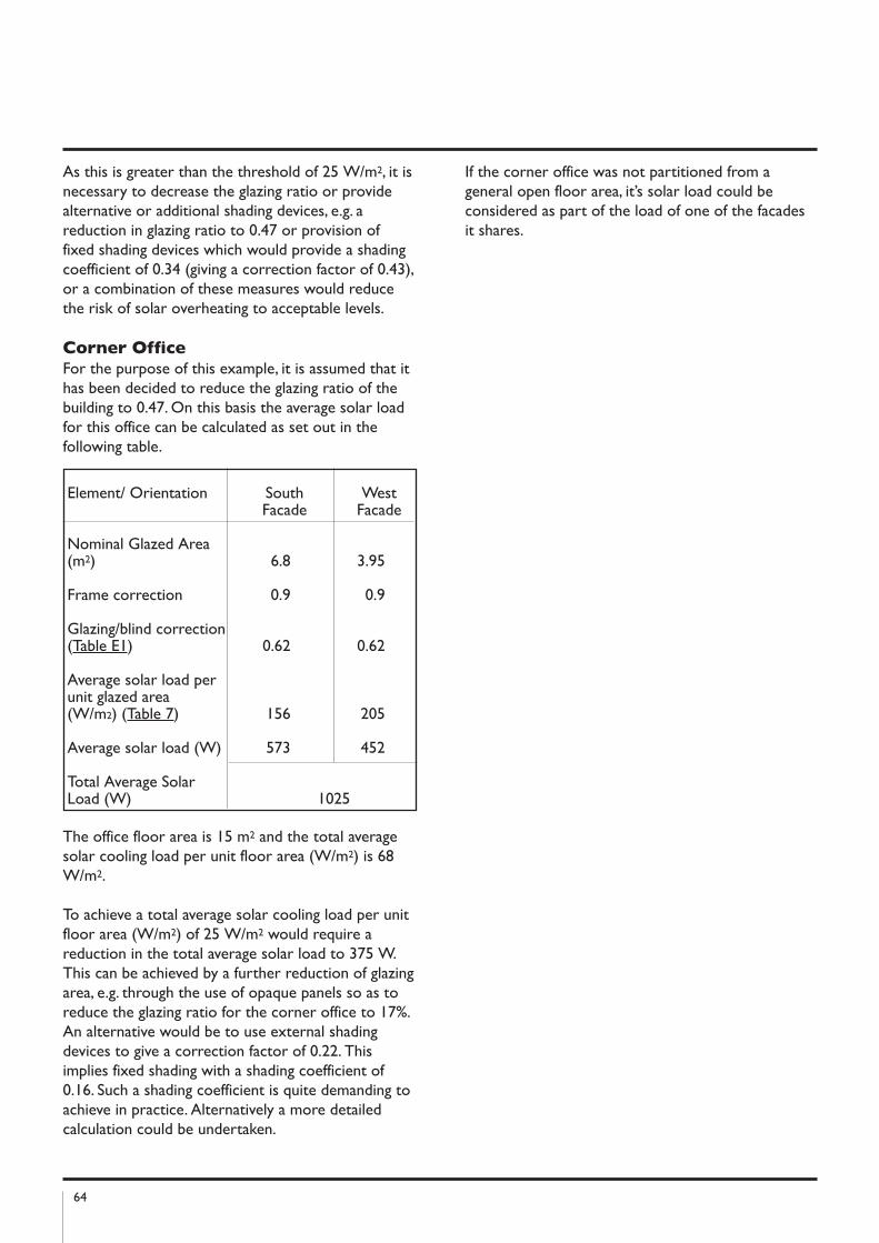
64
As this is greater than the threshold of 25 W/m2, it isnecessary to decrease the glazing ratio or providealternative or additional shading devices, e.g. areduction in glazing ratio to 0.47 or provision offixed shading devices which would provide a shadingcoefficient of 0.34 (giving a correction factor of 0.43),or a combination of these measures would reducethe risk of solar overheating to acceptable levels.
Corner OfficeFor the purpose of this example, it is assumed that ithas been decided to reduce the glazing ratio of thebuilding to 0.47. On this basis the average solar loadfor this office can be calculated as set out in thefollowing table.
The office floor area is 15 m2 and the total averagesolar cooling load per unit floor area (W/m2) is 68W/m2.
To achieve a total average solar cooling load per unitfloor area (W/m2) of 25 W/m2 would require areduction in the total average solar load to 375 W.This can be achieved by a further reduction of glazingarea, e.g. through the use of opaque panels so as toreduce the glazing ratio for the corner office to 17%.An alternative would be to use external shadingdevices to give a correction factor of 0.22. Thisimplies fixed shading with a shading coefficient of0.16. Such a shading coefficient is quite demanding toachieve in practice. Alternatively a more detailedcalculation could be undertaken.
If the corner office was not partitioned from ageneral open floor area, it’s solar load could beconsidered as part of the load of one of the facadesit shares.
Element/ Orientation South WestFacade Facade
Nominal Glazed Area(m2) 6.8 3.95
Frame correction 0.9 0.9
Glazing/blind correction (Table E1) 0.62 0.62
Average solar load per unit glazed area (W/m2) (Table 7) 156 205
Average solar load (W) 573 452
Total Average Solar Load (W) 1025
65
Standards and Other References
Standards referred to:
I.S. 161: 1975 Copper direct cylinders for domesticpurposes.I.S. 325-1: 1986 Code of Practice for use of masonry- part 1: Structural use of unreinforced masonry.I.S. EN 1745: 2002 Masonry And Masonry Products -Methods for determining Design Thermal Values. I.S. EN ISO 6946: 1997 Building components andbuilding elements –Thermal resistance and thermaltransmittance – Calculation method Amd 1 2003. I.S. EN ISO 8990: 1997 Thermal insulation –Determination of steady-state thermal transmissionproperties – Calibrated and guarded hot box.I.S. EN ISO 10077-1: 2001 Thermal performance ofwindows, doors and shutters – Calculation ofthermal transmittance – Part 1: simplified method. I.S. EN 10077-2: 2000 Thermal performance ofwindows, doors and shutters – Calculation ofthermal transmittance – Part 2: Numerical methodsfor frames.I.S. EN ISO 10211-1: 1996 Thermal bridges inbuilding construction – heat flows and surfacetemperatures. Part 1 general calculation methods. I.S. EN ISO 10211-2: 2001 Thermal bridges inbuilding construction – heat flows and surfacetemperatures. Part 2 linear thermal bridges.I.S. EN ISO 10456: 2000 Building materials andproducts - procedures for determining declared anddesign thermal values. I.S. EN 12524: 2000 Building materials and products –Hygrothermal properties – Tabulated design values. I.S. EN ISO 12567-1: 2001 Thermal performance ofwindows and doors – Determination of thermaltransmittance by hot box method – Part 1: Completewindows and doors.I.S. EN ISO 13370: 1999 Thermal performance ofbuildings – Heat transfer via the ground – Calculationmethods.I.S. EN ISO 13789: 2000 Thermal Performance ofBuildings – Transmission Heat Loss Coefficient –Calculation Method.I.S. EN 13829: 2000 Thermal Performance ofBuildings: Determination of air permeability ofbuildings: fan pressurisation method.BS 747: 2000 Reinforced bitumen sheets for roofing– Specification.BS 1566 Part 1: 2002 Copper indirect cylinders fordomestic purposes, open vented copper cylinders.Requirements and test methods.BS 5422 : 2001 Method for specifying thermalinsulating materials for pipes, tanks, vessels, ductwork
and equipment (operating within the temperaturerange - 400C to + 7000C).BS 8206 Part 2: 1992 Lighting for buildings. Code ofpractice for daylighting.
Other Publications referred to:
BRE Digest 465, U-values for light steel frameconstruction, BRE, 2002.BRE Information Paper 1/06 Assessing the effects ofthermal bridging at junctions and around openings,BRE, 2001.BRE Information Paper 10/02, Metal cladding:assessing the thermal performance of built-upsystems using ‘Z’ spacers, BRE, 2002BRE Information Paper 1/06 Assessing the affects ofthermal bridging at junctions and around openings,BRE 2006BRE Report BR 262, Thermal Insulation: avoidingrisks, BRE, 2001BRE Report BR 364, Solar shading of buildings, BRE,1999BRE Report BR 443, Conventions for U-valueCalculations, BRE, 2002.BRE Report BR 497, Conventions for calculatinglinear thermal transmittance and temperaturefactors, BRE, 2007CIBSE Guide A: Environmental Design - Section 3:Thermal Properties of Buildings and Components,CIBSE, 1999CIBSE TM 23: Testing Buildings for Air Leakage,CIBSE, 2000Chris Knights and Nigel Potter, Airtightness Testingfor New Dwellings, A BSRIA Guide ,BSRIA, 2006DEHLG, Limiting Thermal Bridging and AirInfiltration - Acceptable Construction Detailsavailabe on www.environ.ieDomestic Energy Assessment Procedure (DEAP) SEI2006 (www.sei.ie)Good Practice Guide 268, Energy efficient ventilationin dwellings – a guide for specifiers, 2006Home-heating Appliance Register of Performance(HARP) database, SEI (www.sei.ie/harp).Heating and Domestic Hot Water Systems fordwellings – Achieving compliance with Part L.MCRMA Technical Paper No. 14, Guidance for thedesign of metal roofing and cladding to comply withApproved Document L2:2001, The Metal Claddingand Roofing Manufacturers Association, 2002SCI Technical Information Sheet 312, Metal cladding:U-value calculation - assessing thermal performanceof built-up metal roof and wall cladding systems using
66
rail and bracket spacers, The Steel ConstructionInstitute, 2002
SI. No. 260 of 1994, European Communities(Efficiency requirements for hot water boilers firedwith liquid or gaseous fuels) Regulations, 1994, TheDepartment of Transport, Energy andCommunications, 1994
Other Useful Standards and Publications
IS EN 14785: 2006 Residential space heatingappliances fired by wood pellets - requirements andtest methods I.S. EN 303-5: 1999 Heating boilers - heating boilersfor solid fuels, hand and automatically stoked,nominal heat output of up to 300 kw - terminologyrequirements, testing and markingPr EN 15270: Pellet burners for small heating boilers- Definitions, requirements, testing, marking(Expected to be adopted as IS EN 15270 in 2008)IS EN 12975-1: 2006 Thermal solar systems andcomponents - solar collectors - part 1: generalrequirements IS EN 12975-2: 2006 Thermal solar systems andcomponents - solar collectors - part 2: test methods IS EN 12976-1: 2006 Thermal solar systems andcomponents - factory made systems - part 1: generalrequirementsIS EN 12976-2 : 2006 Thermal solar systems andcomponents - factory made systems - part 2: testmethodsIS ENV 12977-1: 2001 Thermal solar systems andcomponents - custom built systems - part 1: generalrequirementsIS ENV 12977-2 : 2001 Thermal solar systems andcomponents - custom built systems - part 2: testmethodsISO 9806-1: 1994 Test methods for solar collectors -- part 1: thermal performance of glazed liquid heatingcollectors including pressure drop ISO 9806-2: 1995 Test methods for solar collectors -- part 2: qualification test proceduresISO 9806-3: 1995 Test methods for solar collectors -- part 3: thermal performance of unglazed liquidheating collectors (sensible heat transfer only)including pressure dropIS EN 14511-1: 2004 Air conditioners, liquid chillingpackages and heat pumps with electrically drivencompressors for space heating and cooling - part 1:terms and definitions
IS EN 14511-2 :2004 Air conditioners, liquid chillingpackages and heat pumps with electrically drivencompressors for space heating and cooling - part 2:test conditions IS EN 14511-3: 2004 Air conditioners, liquid chillingpackages and heat pumps with electrically drivencompressors for space heating and cooling - part 3:test methods IS EN 14511-4: 2004 Air conditioners, liquid chillingpackages and heat pumps with electrically drivencompressors for space heating and cooling - part 4:requirementsI.S. EN 12664: 2001 Thermal performance of buildingmaterials and products – Determination of thermalresistance by means of guarded hot plate and heatflow meters method – Dry and moist products oflow and medium thermal resistance.I.S. EN 12667: 2001 Thermal performance of buildingmaterials and products – Determination of thermalresistance by means of guarded hot plate and heatflow meters method – Products of high and mediumthermal resistance.I.S. EN 12828: 2003 Heating systems in buildings -design for water-based heating systems.I.S. EN 12939: 2001 Thermal performance of buildingmaterials and products – Determination of thermalresistance by means of guarded hot plate and heatflow meters method – Thick products of high andmedium thermal resistance.