tr60 conduttori-continui - giovenzana.com · elettriche in tensione. la conducibilità elettrica è...
TRANSCRIPT

MI000002 – rev.01/2018
Mounting instructionsTR60 continuous conductors
Инструкции по монтажу и ПаспортTR60 с медной шиной на протяжку
Istruzioni montaggioTR60 conduttori continui
ENG
RUS
ITA
-
-
-
TR60
…come non perdere la garanzia...how to keep your warranty
…условия гарантии

MI000002 – rev.01/2018
GIOVENZANA INTERNATIONALnella continua ricerca di
miglioramento dei propri prodotti si riserva il diritto di apportare, senza
obbligo di preavviso, tutte le modifiche tecniche e funzionali
contenute nel presente manuale.
MI000002 - rev.01/2018
2
GIOVENZANA INTERNATIONALin its continuous quest for product
improvement, reserves the right to change any of the technical and
functional information in this manual without prior notice.
MI000002 - rev.01/2018
GIOVENZANA INTERNATIONALнаходится в постоянном поиске
усовершенствования своей продукции, оставляет за собой право вносить любые
технические и функциональные изменения внастоящую инструкцию, без обязательства о
предварительном уведомлении.
MI000002 - rev.01/2018
RevisioneRevisionРевизия
DataDateДата
DescrizioneDescriptionОписание
00 01/04/2016EmissioneFirst issueВыпуск
01 16/07/2018Aggiornamento immagini secondo nuovo standard colore bianco RAL 1012Image update according to the new RAL 1012 white color standardМодификация чертежей в соответствии с новым стандартом в связи с изменением на белый цвет RAL 1012

MI000002 – rev.01/2018
Indice Contents Оглавление
1 Premessa Introduction Вступление 4
2 Dati identificazione prodotto Product identification data Идентификационные данные продукции 5
3 Descrizione prodotto Product description Описание продукции 6
4 Legenda simboli usati Symbols legend Легенда используемых символов 7
5 Disposizione conduttori rame Arrangement of the copper conductors Расположение медных проводников 8
6 Caratteristiche tecniche Technical specifications Технические характеристики 9
7 Sicurezza Safety Безопасность 10
8 Garanzia Warranty Гарантия 11
9 Installazione linea: Line Installation: Установка линии 12
9.1 Fissaggio mensole Bracket fixing Крепление кронштейнов 13
9.2 Fissaggio sospensioni Hanger installation Крепление подвесных скоб 15
9.3 Punto fisso Fixed point Точка фиксации 16
9.4 Montaggio barre Rail mounting Монтаж секций шинопровода 17
9.5 Giunzioni Joints Соединительные муфты 19
9.6 Inserimento conduttori Conductor insertion Протяжка медных шин 20
9.7 Alimentazione di testa Head feed Концевой подвод питания 23
9.8 Montaggio ultima barra Installation of last rail Монтаж последней секции шинопровода 26
9.9 Carrelli Trolleys Токосъемники 27
9.10 Staffa doppio carrello Double-trolley support Поводок двойного токосъемника 29
9.11 Inserimento guarnizione e chiusura linea Sealing strip insertion and line termination Вставка уплотнительной ленты и закрытие линии 30
10 Braccio di traino Towing arm Буксирная опора 31
11 Alimentazione intermedia In-line feed Линейный подвод питания 33
12 Prolungamento linea Line extension Продление линии 35
13 Manutenzione Maintenance Техническое обслуживание 37
14 Risoluzione dei problemi Troubleshooting Решение проблем 38
3

MI000002 – rev.01/2018
1PREMESSA
Questo manuale contiene tutte le istruzioni necessarie per una corretta posa e messa in
servizio della linea di alimentazione serie TR60.
Le operazioni contenute in questo manuale devono essere eseguite da personale
specializzato e qualificato.Necessaria:
§ conoscenza di norme generali circa la sicurezza§ conoscenza di norme circa prevenzione infortuni§ conoscenza di norme circa installazioni elettriche§ competenza nell’ usare attrezzature elettriche
L’ installatore ha l’ obbligo di seguire queste istruzioni in modo da assicurare un funzionamento
duraturo e costante nel tempo come pure garantire sicurezza nell’ utilizzare questo
prodotto.
La non osservazione di queste istruzioni può comportare seri danni sia all’ apparecchiatura
stessa, sia all’ operatore.
In caso di installazioni straordinarie e/o che richiedono una diversa configurazione non
presente in questo manuale si prega di rivolgersi immediatamente al supporto tecnico GIOVENZANA INTERNATIONL B.V.
Qualsiasi disegno o documento addizionale specifico contenuto nel componente fornito
prende priorità su questo manuale.
4
ВСТУПЛЕНИЕ
Данное пособие включает в себя все необходимые инструкциипо установке и подключению линии питания серии TR60.
Все действия, описанные в данном пособии, должны бытьвыполнены специализированным и квалифицированнымперсоналом.Требуются:§общие знания норм безопасности§общие знания по предотвращению травмоопасных ситуаций§знание норм по установке электрического оборудования§компетентность в использовании электрическогооборудования
Монтажник обязан следовать инструкциям для обеспечениядолговечной и стабильной работы линии и гарантиибезопасности в использовании данного изделия.
Невнимательное изучение инструкций может привести ксерьезным повреждениям оборудования и травмамобслуживающего персонала.
В случае необходимости дополнительных установок и/илиизменения конфигурации, не присутствующих в данномпособии, следует незамедлительно обратиться к службеТехнической Поддержки GIOVENZANA INTERNATIONAL B.V.
Любой чертеж или дополнительный уточненный документ, предоставленный вместе с изделием, имеет приоритет надданным пособием.
INTRODUCTION
This manual contains all the necessary instructions for the correct installation and commissioning of
the TR60 series busbar system.
The operations described in this manual must be performed by fully qualified and specialized
personnel.Requisites:
§ knowledge of general safety regulations§ knowledge of accident prevention regulations§ knowledge of electrical installation standards§ skilled in the use of electrical tools and equipment
The installer is required to follow these instructions in order to ensure both long-term reliable
functioning and safety in using this product.
Non-observance of these instructions may result in both operator injury and/ severe damage to the
equipment.
In the event case of special installations and/or those that require a different configuration not
present in this manual, please contact GIOVENZANA INTERNATIONAL B.V. technical
support.
Any additional drawing or document provided with the supplied component takes priority over this
manual.

MI000002 – rev.01/2018
2DATI DI IDENTIFICAZIONE
DEL PRODOTTO
Il profilo esterno è marchiato in maniera indelebile e fornisce le seguenti informazioni:
Certificazione:
Posizionamento conduttore di terra:
(la linea continua nera abbinata al simbolo di terra indica chiaramente la posizione del conduttore di terra)
Provenienza: MADE IN ITALY
Produttore: GIOVENZANA Int.
Data di produzione: giorno/mese/anno
Serie: TR60
§ Colore esterno barra: standard giallo(su richiesta colori personalizzati)
1
2
3
4
5
6
21 3 4 5 6
5
PRODUCT IDENTIFICATIONDATA
The busbar rail is indelibly marked on the outside and provides the following information:
Certification:
Positioning of earth conductor:
(the continuous black line combined with the earth symbol clearly indicates the position of the earth conductor)
Place of origin: MADE IN ITALY
Manufacturer: GIOVENZANA Int.
Date of manufacture: day/month/year
Series: TR60
§ External rail colour: standard yellow(personalized colours upon request)
ИДЕНТИФИКАЦИОННЫЕ ДАННЫЕПРОДУКЦИИ
Внешний профиль помечен несмываемыми надписями ипредоставляет следующую информацию:
Сертификат:
Заземление:
(Черная линия совместно с символом заземления указывает нарасположения заземляющего проводника)
Страна-изготовитель: СДЕЛАНО В ИТАЛИИ
Производитель: GIOVENZANA Int.
Дата изготовления: день/ месяц/ год
Серия: TR60
§ Цвет корпуса шинопровода: стандарт- желтый(другие цвета на заказ)
1
2
3
4
5
6
1
2
3
4
5
6

MI000002 – rev.01/2018
3DESCRIZIONE PRODOTTO
La linea di alimentazione isolata TR60 è un sistemamoderno e antinfortunistico per la trasmissione dienergia per vari tipi di utenze mobili: gru,carriponte, paranchi, sistemi a nastro… .La linea è costituita da un involucro in PVC cui lamisura standard delle barre è di 4 metri ocomunque riducibile secondo necessitasemplicemente tagliando l’ultima barra a misura.Ogni barra è collegabile l’ una all’ altra medianteplacche di congiunzione e sostenuta mediantesupporti e a seconda della tipologia di linea, saràcomposta da una alimentazione di testa oppureun’ alimentazione intermedia sulla linea e infine daun tappo (due se tipologia con alimentazioneintermedia) di chiusura linea.Dentro l’ involucro in PVC verranno inseriti n°conduttori elettrici sotto forma di piattina di ramefino ad un massimo di cinque.La trasmissione elettrica è affidata ad uno o piùcarrelli completamente isolati che scorrendo all’interno della barra non lasciano esposte partielettriche in tensione. La conducibilità elettrica ègarantita da spazzole in metal-grafite cheassicurano prestazioni, minime cadute di tensionee affidabilità di servizio nel tempo. Inoltre i carrellisono provvisti di ruote per cui scorrono senzaattrito all’ interno del profilo e predisposti peraccogliere un supporto/staffa di traino checollegato all’ utenza mobile permette di trascinareil carrello parallelamente ad essa.Per l’installazione all’ aperto o in zoneparticolarmente polverose, la barra è predispostaper l’ applicazione di una guarnizione in gomma chene aumenta il grado di protezione.Giovenzana Int. realizza perfino la versioneTR85H7P può accogliere fino a n° 7 conduttoricombinando anche diverse connessioni in paralleloper aumentarne la portata.
6
PRODUCT DESCRIPTION
The TR60 insulated busbar line is a modern andsafe system for energy transmission on varioustypes of mobile equipment: cranes, gantries,hoists, conveyor belt systems, etc.The line consists of a PVC casing made of rails witha standard length of 4 metres; the line can beshortened as required by simply cutting the lastrail. Each rail can be connected to another usingjoint plates and is supported by supports, while theline, according to type, will have a head feed or anin-line feed along the line and an end cap (two forthe in-line feed type) for line termination.Up to a maximum of five electrical conductors, inthe form of copper strips, can be inserted insidethe PVC casing.The transmission of electricity is provided by oneor more fully insulated trolleys that run inside thebar and without leaving any live parts exposed.Electrical conductivity is guaranteed by metal-graphite shoes, which ensure good performance,minimal voltage drops and long service lifereliability. In addition, the trolleys are equipped withwheels, allowing them to run friction-free inside thechannel, and designed to engage a towsupport/bracket, which, connected to themovable load, allows towing the trolley parallel to it.For installation outdoors or in particularly dustyareas, the rail is designed to accept a rubbersealing strip that increases the level of protection.Giovenzana Int. even produces the TR85H7Pversion, which can accept up to seven conductors,also combining several connections in parallel toincrease capacity.
ОПИСАНИЕ ПРОДУКЦИИ
Линия троллейных шинопроводов TR60 – это современная ибезопасная система передачи электроэнергии для различныхтипов оборудования, таких как: тали, мостовые краны, ленточные и цепные конвейеры и т.д.Линия представляет собой корпус из ПВХ. Стандартная длинасекций 4 метра. Длину линии очень просто укоротить, отрезав фрагмент последней секции.Проводники на каждой секции соответственноподсоединяются друг к другу с помощью специальныхстыковочных зажимов, чтобы обеспечить безопасное инадежное электрическое соединение.Секции шинопровода подсоединяются друг к друг с помощьюсоединительных муфт и поддерживаются на кронштейнах, Взависимости от типа линии, шинопровод состоит еще изконцевого или линейного подвода питания и заглушки, замыкающей линию (две заглушки с линейным подводомпитания).Передача электроэнергии осуществляется посредством одногоили более полностью изолированных токосъемников, которыепередвигаются внутри шинопровода, не оставляя оголеннымитокопроводящие части.Электропроводность обеспечивается металлографитнымищетками, которые гарантируют производительность, минимальные перепады напряжения и надежность работы напротяжении длительного времени. Кроме того токосъемникиснабжены роликами, благодаря чему передвигаются внутришинопровода без трения. Они предназначены дляподсоединения буксирной опоры, в свою очередьприкрепленной на передвижном механизме, котораяпозволяет перемещать токосъемник параллельно самомумеханизму.Для установки линии на открытом воздухе или в особопыльных помещениях, шинопровод оснащен выемками длярезиновой уплотнительной ленты, которая повышает степеньзащиты.Giovenzana International также реализует версиюTR85H7P, в которой можно провести до 7 проводников, комбинируя разные виды подключения для увеличениямощности.
MI000002 – rev.01/2018
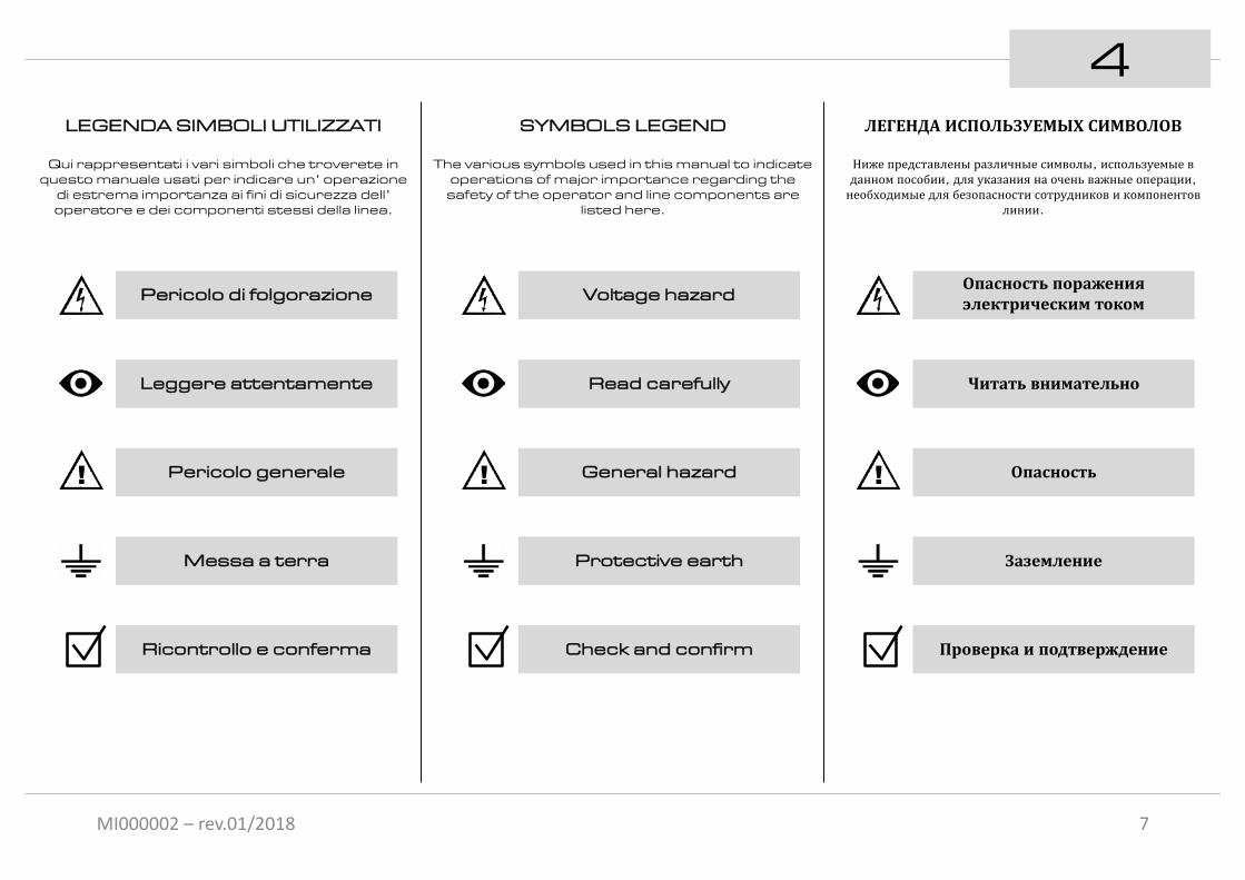
4LEGENDA SIMBOLI UTILIZZATI
Qui rappresentati i vari simboli che troverete in questo manuale usati per indicare un’ operazione
di estrema importanza ai fini di sicurezza dell’ operatore e dei componenti stessi della linea.
Pericolo di folgorazione
Leggere attentamente
! Pericolo generale
Messa a terra
Ricontrollo e conferma
7
SYMBOLS LEGEND
The various symbols used in this manual to indicate operations of major importance regarding the
safety of the operator and line components are listed here.
ЛЕГЕНДА ИСПОЛЬЗУЕМЫХ СИМВОЛОВ
Ниже представлены различные символы, используемые вданном пособии, для указания на очень важные операции, необходимые для безопасности сотрудников и компонентов
линии.
Voltage hazard
Read carefully
! General hazard
Protective earth
Check and confirm
Опасность пораженияэлектрическим током
Читать внимательно
! Опасность
Заземление
Проверка и подтверждение

MI000002 – rev.01/2018
DISPOSIZIONECONDUTTORI DI RAME
Le immagini mostrano la disposizione dei conduttori
ATTENZIONE:
A titolo preferenziale si attribuisce la posizione del conduttore di neutro nel vano alto della barra
Il conduttore di terra è contrassegnato dalla
linea continua nera e dal simbolo di terra.
5
8
N
PE
32
1
ARRANGEMENT OF THECOPPER CONDUCTORS
The pictures shows the position of theconductors
WARNING:
The position of the neutral conductor is preferably assigned to the upper slot of the rail.
РАСПОЛОЖЕНИЕ МЕДНЫХПРОВОДНИКОВ
На изображениях указано расположение медныхпроводников
ВНИМАНИЕ:
Нейтральный проводник преимущественно располагается вверхнем проеме корпуса шинопровода.
The earth conductor is marked by a continuous black line and the earth
symbol.
Заземляющий проводникотмечен черной линией исимволом заземления

MI000002 – rev.01/2018
CARATTERISTICHE TECNICHE:
6
9
TECHNICAL SPECIFICATIONS: ТЕХНИЧЕСКИЕ ХАРАКТЕРИСТИКИ:
Tabella peso (barra completa di conduttori)Busbar rail weight table (complete with conductors)Таблица определения веса шинопровода (с проводником)
40 A 60 A
§ N° CONDUTTORI
§ CONDUCTORS NO.
§ № ПРОВОДНИКОВ
4 1.034 kg/m 1.290 kg/m
5 1.120 kg/m 1.440 kg/m
Temperatura ambienteAmbient temperatureТемпература окружающей среды
EsercizioOperating
Pабочая
StoccaggioStorageXранения
-30°C … +55°C -30°C … +70°Cmin MAX

MI000002 – rev.01/2018
7
10
БЕЗОПАСНОСТЬ
Во время установки или технического обслуживания линиинеобходимо убедиться в следующем:
§ наличие бригады из минимум двух человек.
§ придерживаться правил безопасности во время работы.
§ использовать форму и средства индивидуальной защиты, предусмотренные действующими нормами.
§ использовать утвержденное и соответствующеедействующим нормам оборудование для подъема (лестницы, леса, подъемные платформы..), во избежание опасныхситуаций во время передвижения.
§ подготовить все необходимое для страховки, в случаепроведения работ на значительной высоте.
§ Увести посторонних из зоны установки линии.
SICUREZZA
Durante le operazioni di installazione o di manutenzione della linea occorre assicurarsi di:
§ staff composto da almeno due persone.
§ attenersi al piano di sicurezza sul lavoro.
§ indossare o utilizzare i dispositivi individuali di protezione previsti dalle norme vigenti.
§ utilizzare attrezzature di sollevamento (scale, ponteggi, piattaforme elevatrici..) omologate e rispondenti alle norme vigenti prevenendo situazioni di pericolo durante la movimentazione.
§ prevedere tutti gli equipaggiamenti di sicurezza in caso di installazione ad altezze elevate.
§ allontanare le persone estranee all’ installazione della linea.
SAFETY
Ensure the following during line installation or maintenance operations:
§ team composed of at least two people.
§ keep to the safety at work regulations.
§ wear/use the personal protective equipment provided for by current regulations.
§ use type-approved lifting equipment (ladders, scaffolding, lifting platforms, etc.) in conformity with current regulations, and avoid hazardous situations when handling.
§ provide safety equipment in the case of installation at large heights.
§ keep persons not involved in line installation away from work area.
Work with power disconnected
from the line and ensure that under no
circumstances can the line be powered up, even
accidentally.
Operare in assenza ditensione sulla linea e
assicurarsi che in nessun caso possa essere,
anche accidentalmente, messa in tensione.
Работать без напряженияУбедиться, что напряжениеотключено и не может быть
случайно включено.

MI000002 – rev.01/2018
8
11
CONDIZIONI DI GARANZIA
§ La durata standard del periodo di garanzia per i prodotti Giovenzana International B.V. è di due anni. La condizione di garanzia è di tipo carry-in, cioè presso GiovenzanaInternational B.V.
§ Durante il periodo di garanzia, il Controllo Qualità della Giovenzana International B.V. riparerà eventuali guasti che risultino da difetti di fabbricazione o di materiali. Se il Controllo Qualità della Giovenzana International B.V. ritiene impossibile porre rimedio alle suddette mancanze, sostituirà i componenti che, a suo giudizio, hanno la medesima funzione delle apparecchiature da sostituire, in tal caso la proprietà dei componenti sostituiti sarà di Giovenzana International B.V.
§ La garanzia è limitata alla riparazione o alla sostituzione delle parti. Il Controllo Qualità della Giovenzana International B.V. non è in alcun caso responsabile per ulteriori mancanze o difetti.
§ Le spese di riparazione e/o sostituzione dei prodotti in garanzia sono a carico della società GiovenzanaInternational B.V. mentre le spese di trasporto sono a carico del cliente.
§ Il Cliente deve far pervenire al Controllo Qualità della Giovenzana International B.V. il prodotto con allegato unaspiegazione dettagliata del problema.
§ L’obbligo di garanzia decade se:1) il Cliente modifica o ripara il prodotto oppure
lo fa modificare o riparare da persone non autorizzate.
2) il Cliente utilizza il prodotto per scopi diversi da quelli normalmente previsti e/o lo espone a condizioni diverse da quelle di normale utilizzo.
3) Il Cliente utilizza o mantiene quanto fornito in modo sbagliato, negligente o improprio.
4) L’etichetta Guarantee seal è stata rimossa, danneggiata o manomessa.
§ L’obbligo di garanzia di Giovenzana International B.V. non è applicabile:
1) ai materiali non forniti da GiovenzanaInternational B.V.
2) se i difetti sono il risultato della normale usura.3) se i difetti risultano da cause esterne, quali
fuoco o acqua, fulmini, sinistri, azioni moleste, terremoti o guerra.
4) se risulta chiaro che non esiste alcun diritto di garanzia, tutte le eventuali spese di analisi tecnica, riparazione o sostituzione saranno a carico del cliente.
WARRANTY CONDITIONS
§ The standard duration of the warranty period for Giovenzana International B.V. products is two years. The warranty is of the carry-in type, i.e. provided at GiovenzanaInternational B.V. premises.
§ During the warranty period, Giovenzana International B.V. Quality Control shall repair all faults arising from manufacturing or material defects. If GiovenzanaInternational B.V. Quality Control deems that the aforementioned faults cannot be repaired, it will replace components with those it considers to have the same function as the equipment to be replaced; in this case, the replaced components will be the property of GiovenzanaInternational B.V.
§ Warranty is limited to the repair or substitution of parts. Giovenzana International B.V. Quality Control is not in any way responsible for further faults or defects.
§ The costs of repair and/or replacement of products under warranty are borne by Giovenzana International B.V. while shipping costs are at the customer’s expense.
§ The Customer must deliver the product to GiovenzanaInternational B.V. Quality Control, together with a detailed description of the problem.
§ The warranty is no longer valid if:1) the Customer modifies or repairs the product
or has it modified or repaired by unauthorized persons.
2) the Customer uses the product for purposes other than those normally envisaged and/or exposes it to conditions other than those of normal use.
3) the Customer uses or keeps what has been supplied in a wrong, negligent or improper manner.
4) the Guarantee seal has been removed, damaged or tampered with.
§ The Giovenzana International B.V. warranty is not applicable:
1) to materials not supplied by GiovenzanaInternational B.V.
2) if the defects derive from normal wear.3) if the defects derive from external causes,
such as fire or water, lightning, accidents, vandalism, earthquakes or war.
4) if it is clear that of no warranty rights exist, all expenses for technical analysis, repair or replacement shall be at the customer’s expense.
УСЛОВИЯ ГАРАНТИИ
§ Стандартная продолжительность гарантийного срока для продукцииGiovenzana International B.V. составляет два года. Гарантиятипа “carry-in”, т.е. на заводе Giovenzana International B.V.
§ В течение гарантийного срока, отдел “Контроль Качества”Giovenzana International B.V. выполнит ремонт любыхнеисправностей, которые являются результатом дефекта фабрики илиматериала. В случае если отдел “Контроль Качества” решит, чтонеисправности не могут быть устранены, неисправные компонентыбудут заменены на подобное им. В таком случае замененныекомпоненты будут собственностью Giovenzana International B.V.
§ Гарантия ограничивается ремонтом и/или заменой деталей. Отдел“Контроль Качества” Giovenzana International B.V. ни в коемслучае не несет ответственность за последующие недостачи илидефекты.
§ Расходы на ремонт и/или замену изделий по гарантии берет на себяGiovenzana International B.V., в то время как транспортныерасходы будут за счет клиента.
§ Клиенту необходимо доставить изделие в отдел “КонтрольКачества” Giovenzana International B.V. с подробнымописанием проблемы.
§ Гарантия больше не действует в случае если: 1) Клиент модифицировал или ремонтировал изделие или это было
сделано неуполномоченными лицами.2) Клиент использует изделие не по назначению и/или
эксплуатирует его в условиях, отличающихся от нормы.3) Клиент использует или хранит приобретенные изделия
неправильным, небрежным или неподходящим образом.4) Гарантийный знак был удален, поврежден или подделан.
§ Гарантия Giovenzana International B.V. не распространяется:1) на материалы не принадлежащие Giovenzana International
B.V.2) если дефект вызван естественным износом.3) если дефект вызван внешними факторами, такими как: огонь,
вода, молнии, несчастные случаи, вандализм, землетрясения иливойна.
4) если определенно ясно, что права на гарантию нет. В такомслучае все расходы на технические анализы, ремонт и заменуберет на себя клиент.

MI000002 – rev.01/2018
INSTALLAZIONELinea esempio con distanza tra i supporti di
1.33 metri ( n° 3 supporti per barra)
9
12
1.33m
1.33m
0.67 m
1.33 m
1.33 m
1.33m
1.33m
1.33m
1.33 m
0.67 m 0.67 m0.67 m 0.67 m
УСТАНОВКА ЛИНИИПример установки линии с дистанцией между креплениями в
1.33 метра ( 3 крепления на секцию)
INSTALLATIONLine example with distance between supports of
1.33 metres (No. 3 supports per busbar rail)

MI000002 – rev.01/2018
FISSAGGIO MENSOLE
§ Dis. 1: Preparare le staffe supporti della linea ad intervalli regolari come esposto nel disegno.
§ Dis.2 : Forare, se non già previsto, il supporto con punta Ø9 mm.
§ Dis.3 : Sebbene il supporto di traino del carrello ammette eventuali dislivelli della linea in senso verticale ma anche in senso laterale (imperfetto parallelismo) entro qualche centimetro, è bene comunque curare e verificare l’ allineamento dei supporti.Volutamente in disegno il terzo supporto da sinistra è stato indicato errato per far meglio intendere come rispettare l’ allineamento.L’ allineamento verticale può essere perfezionato grazie alle sospensioni che permettono di correggere eventuali dislivelli fino ad un massimo di qualche centimetro semplicemente regolando il controdado.Vedi pag. 15.
9.11
2
3
Si raccomanda di montare la staffa iniziale a 67 cm dall’ estremità della linea per supporti passo 1.33 m in modo
che le sospensioni poi si trovino sempre
sufficientemente vicino alle giunzioni per un
adeguato sostegno.Vedi illustrativo pag. 12
LMAX
1.33m
LMAX
1.33m
Ø9 mm
!
!
13
BRACKET FIXING
§ Dwg. 1: Prepare the line support brackets at regular intervals as indicated in the drawing.
§ Dwg. 2 : If not already provided, drill a hole in the bracket with aØ9 mm drill.
§ Dwg. 3 : Although the trolley towing arm allows possible vertical as well as sideways (imperfect parallelism) variations in the line of a few centimetres, it is still recommended to pay attention to and check the alignment of supports.The third from left bracket has be purposely offset to better understand how to respect alignment.Vertical alignment can be improved via the hangers, which allow correcting possible differences in height of up to a few centimetres by simply adjusting the check nut.See page 15.
It is recommended to install the first bracket
67 cm from the line end for supports spaced
every 1.33 m so that the hangers are always
located sufficiently close to the joints to provide
adequate support.See illustration on page
12
КРЕПЛЕНИЕ КРОНШТЕЙНОВ
§ Рис.1: Расположить опорныекронштейны линии на равном расстоянии, как указано на рисунке.
§ Рис.2: Если не предусмотрено, просверлить опорные кронштейнысверлом диаметром 9мм.
§ Рис.3: Несмотря на то, что в случае сбуксирной опорой допустимы возможныенеровности линии по вертикали игоризонтали в пределах несколькихсантиметров (несовершенныйпараллелизм), в любом случае необходимосделать и проверить выравниваниекронштейнов.На рисунке третий кронштейн слева былумышленно расположен неправильно, чтобы лучше понять как работаетвыравнивание.Вертикальное выравнивание можноподогнать благодаря подвесным скобам, которые позволяют корректироватьотклонения в пределах несколькихсантиметров, всего лишь регулируяконтргайку. Смотри на стр. 15
Рекомендуется закрепитькрайние кронштейны на
расстоянии 67 см от концалинии (для кронштейнов сшагом в 1.33 м), чтобы
подвесные скобы находилисьблизко к соединительным
муфтам для соответствующейподдержки.
Смотрите рисунок на стр.12

MI000002 – rev.01/2018
9.14
5
6
TR8550 L = 350 mm
TR8551 L = 500 mm
TR8552 L = 700mm
TR8555 L = 350 mm
TR8556 L = 500 mm
17mm
14
FISSAGGIO MENSOLE
Se l’ impianto non è dotato di supporti già predisposti, sono disponibili come accessori due tipologie staffe sostegno di diverse lunghezze.
§ Dis. 4: mostra le staffe sostegno fissaggio su trave.
§ Dis. 5: mostra il montaggio delle staffe sostegno fissaggio su trave.
§ Dis. 6: mostra le staffe sostegno fissaggio a muro(viti e fischer non forniti).
Si raccomanda scegliere la corretta lunghezza dei
supporti in modo tale che il braccio o forca fissato al dispositivo
mobile possa intercettare la staffa di
traino del carrello.Vedi pag. 31
Spessore trave:5 / 15 mm (min/MAX)
Fare attenzione al corretto senso di
posizionamento delle piastrine.
BRACKET FIXING
If the plant is not equipped with suitable supports, two types of support beam are available in various lengths as accessories.
§ Dwg. 4: shows the support clips for beam mounting.
§ Dwg. 5: shows the installation of beam-mounted support clips.
§ Dwg. 6: shows the support brackets for wall mounting(screws and wall plugs not provided).
It is advised to choose the correct length for
the supports so that the arm or fork fixed to the
mobile device can reach the trolley’s towing
bracket.See page 31
Take care to ensure positioning the clips the
right way round.
Beam thickness:5 / 15 mm (min/MAX)
КРЕПЛЕНИЕ КРОНШТЕЙНОВ
В случае если система не оснащенакронштейнами, в наличии имеются двавида опорных кронштейнов различнойдлины.
§ Рис. 4: изображение опорныхкронштейнов для крепления на двутавр.
§ Рис. 5: монтаж опорных кронштейновна двутавр.
§ Рис. 6: изображение опорногокронштейна для крепления на стену.
Рекомендуется подобратьправильную длинукронштейнов, чтобыбуксирная опора,
закрепленная на движущемсяустройстве, могла захватить
буксирную опорутокосъемника.
Смотреть стр. 31
Обратите особое внимание направильное размещение
зажимов.
Толщина двутавра:5 / 15 мм (мин/МАКС)

MI000002 – rev.01/2018
9.27
8
9
13mm
15
FISSAGGIO SOSPENSIONI
§ Dis. 7: mostra i due tipi di sospensioni disponibili ed entrambe fornite con due dadi flangiati M8.§TR6002 in materiale plastico§TR6020 in acciaioSi raccomanda di utilizzare la sospensione opportuna verificando la compatibilità del materiale plastica o acciaio con l’ atmosfera di posa della linea.
§ Dis. 8: montare le sospensioni senza serrare entrambi i dadi.
§ Dis. 9: regolare il controdado in modo tale che tutte le sospensioni siano alla stessa altezza e completare il fissaggio serrando dado e controdado.
HANGERINSTALLATION
§ Dwg. 7: shows the two types of hangers available, both supplied with two M8 flanged nuts.§TR6002 in plastic§TR6020 in steelIt is recommended to use the appropriate hanger, checking compatibility of the plastic or steel with the line installation environment.
§ Dwg. 8: mount the hangers without tightening both nuts.
§ Dwg. 9: adjust the check nut so that all the hangers are at the same height and complete installation by tightening the nut and check nut.
КРЕПЛЕНИЕПОДВЕСНЫХ СКОБ
§ Рис.7: здесь изображены два видаподвесных скоб, имеющихся в наличии вкомплекте с двумя фланцевыми гайкамиМ8.§TR6002 из пластмассы§TR6020 из сталиРекомендуется использовать подходящиеподвесные скобы, заранее проверив насовместимость пластмассу или сталь сосредой в которой устанавливается линия.
§ Рис.8: установить подвесные скобы, незатягивая гайки.
§ Рис.9: отрегулировать контргайкитаким образом, чтобы все скобы были наодном уровне и завершить крепление, затянув гайки и контргайки.
TR6002(plastica)(plastic)
(пластмасса)
TR6020(acciaio)
(steel)(сталь)

MI000002 – rev.01/2018
9.310
11
12
16
13mmTR6014
DilatazioneExpansionРасширение
DilatazioneExpansionРасширение
DilatazioneExpansionРасширение
PUNTO FISSO
§ Dis. 10: mostra il punto fisso che, montato al posto di una sospensione, ha la funzione di ripartire correttamente la dilatazione termica della linea.Mentre le sospensioni consento il normale scorrimento della barra al loro interno, il punto fisso va completamente a bloccare la barra evitando il movimento.
§ Per il montaggio fare riferimento al montaggio della giunzione a pag.19, praticando due asole sul profilo barra per consentirne il corretto bloccaggio.
Si raccomanda di creare il punto fisso in prossimità
dell’ alimentazione:
Dis. 11: tipologia linea con ALIMENTAZIONE di
TESTA: un solo punto fisso posizionato subito nel primo troncone linea.
Dis. 12: tipologia linea con ALIMENTAZIONE di
INTERMEDIA: due punti fissi posizionato subito nel troncone linea di destra e
di sinistra dell’ alimentazione intermedia.
Se presenti due alimentazioni intermedie il
punto fisso (uno solo) andrà a collocarsi a metà tra le due alimentazioni.
Рекомендуется установить точкуфиксации вблизи с подводом
питания.
Рис.11: тип линии с КОНЦЕВЫМПОДВОДОМ ПИТАНИЯ: одна точкафиксации, расположенная на
муфте.
Рис.12: тип линии с ЛИНЕЙНЫМПОДВОДОМ ПИТАНИЯ: две точкификсации, расположенные на
муфтах (одна справа, другая слеваот подвода питания).
При наличии двух линейныхподводов питания, точкуфиксации (одну) надо
расположить посередине междудвумя подводами питания.
ТОЧКА ФИКСАЦИИ
§ Рис.10: здесь изображена муфта дляточки фиксации, имеющая функциюподвесной скобы, а также служитмеханизмом для правильногораспределения термического расширениялинии.В то время как скобы дают возможностьшинопроводу свободно скользить вдоль, точка фиксации полностью блокируетдвижение шинопровода.
§Для монтажа брать за пример установкусоединительных муфт на стр.19, Делаядва выступа на профиле бар дляобеспечения надлежащего блокировки.
FIXED POINT
§ Dwg. 10: shows the fixed point, which mounted in place of a hanger, has the function of correctly distributing the thermal expansion of the line.While the hangers allow normal slippage of the busbar within them, the fixed point completely locks the bar, preventing any movement.
§ For installation, please refer to joint installation on page 19, making two lugs on the bar profile to allow for proper locking.
It is recommended to install the fixed point
close to the power supply feed:
Dwg. 11: line with HEAD FEED: only one fixed point positioned near the joint,
on the second line segment.
Dwg. 12: line with IN-LINE FEED: two fixed points
positioned near the joint, one to the left and one to
the right of the power feed.
If there are two in-line feeds, the fixed point (only
one) should be located halfway between the two
feeds.

MI000002 – rev.01/2018
MONTAGGIO BARRE
Agganciare le barre alle sospensioni. L’ inserimento avviene a pressione in maniera semplice e veloce in quanto le sospensioni sono abbastanza elastiche da permettere l’ inserzione della barra fino alla posizione di aggancio.
9.413
14
15
Verificare il corretto aggancio della barra
controllando la stabilità.
Dis. 15: mostra le installazioni corrette ed
errate delle barre.
Click!
17
I. III.II.
RAIL MOUNTING
Clip the busbar rails onto the hangers. The press-fit engagement is quick and simple, as the hangers are sufficiently elastic to allow insertion of the rail into the coupling position.
Control that rail is correctly coupled and
check its stability.
Dwg. 15: shows correct and incorrect rail
installations.
МОНТАЖ СЕКЦИЙШИНОПРОВОДА
Вставьте секции шинопровода в подвесныескобы. Для сцепления необходимо лишьнадавить,. Подвесные скобы достаточноэластичные для полной стыковки секций.
Проконтролировать правильностьстыковки шинопровода,
проверить устойчивость линии.
Рис.15: здесь изображеныправильная и неправильнаяустановка шинопровода.

MI000002 – rev.01/2018
9.4RAIL MOUNTING МОНТАЖ СЕКЦИЙ
ШИНОПРОВОДА16
17
18
§ Dis. 18: Per il momento NON montare l’ ultimo
spezzone di barra dal lato tappo chiusura linea.
(servirà poi per riuscire a far arretrare i conduttori di rame una volta inseriti)
§ Dis. 18: la distanza tra la sospensione e la
giunzione non deve essere inferiore a 50 mm
18
lato tappo finaleend cap side
сторона заглушки
lato alimentazionefeed sideсторона подвода питания
50 mm 50 mm
§ Рис. 16: Обратить особоевнимание на то, чтобы
установить все секции с однойстороны. Берем за ориентирчерную сплошную линию с
внешней сторонышинопровода.
§ Рис. 17: Еще разпроконтролировать
шинопровод на выравнивание(вертикальное и
горизонтальное). Принеобходимости, повторноотрегулировать подвесныескобы по вертикали, как
указано на стр.15.
§ Dwg. 17: Control rail alignment again, both
vertically and sideways, and if necessary proceed
with further height adjustment of the
hangers as shown on page 15.
§ Dwg. 16: Take care to mount all busbar rails in
the same direction, using the external continuous black line as a reference
§ Dwg. 18: For the moment, DO NOT install the last length of rail on
the end-cap side.
(serves later for withdrawing the copper
conductors once inserted)
§ Dwg. 18: the distance between hanger and joint
must not be less than50 mm
Рис. 18: на данный моментНЕ устанавливать последнююсекцию со стороны заглушки.(она понадобится позже дляотвода протянутых медных
проводников)
Рис. 18 расстояние междуподвесной скобой и
соединительной муфтойдолжно быть больше 50мм
§ Dis. 16: Prestare attenzione a montare
tutte le barre nello stesso lato tenendo
come riferimento la linea continua esterna nera
§ Dis. 17: Verificare nuovamente
allineamento barre sia in senso verticale sia
laterale e se necessario procedere ancora alla
regolazione delle sospensioni in altezza
come mostrato a pag.15.
MONTAGGIO BARRE

MI000002 – rev.01/2018
9.519
20
21
GIUNZIONI
§ Dis. 19: mostra la giunzione tra due barre.Ha la particolarità di avere due naselli (Dis. 20) per ogni semiguscio che si inseriscono nelle apposite sedi su ciascun spezzone di barra. Con questo sistema si impedisce lo sfilamento delle barre.
§ Dis. 20-21: mostra la sequenza di montaggio della giunzione in plastica.
TR6001(plastica)(plastic)
(пластмасса)
19
Chiusura giunzione a scatto, nessun attrezzo
richiesto o necessario
Click!
СОЕДИНИТЕЛЬНЫЕ МУФТЫ
§ Рис. 19: изображение соединительноймуфты между двумя секциями.На каждой половинке муфты имеются двазубца (Рис. 20) которые вставляются вспециальные отверстия на каждомфрагменте секции. Благодаря этойсистеме, предотвращается скольжениешинопровода.
§ Рис. 20-21: показываютпоследовательность монтажа пластиковыхсоединительных муфт.
Чтобы закрыть муфту, необходимо просто щелкнуть. Не
требуется дополнительноеоборудование
JOINTS
§ Dwg. 19: shows the joint between two rails.It features two coupling lugs (Dwg. 20) for each half-shell that engage with specially provided seats on each rail section. This system prevents rails from slipping out.
§ Dwg. 20-21: shows the plastic joint mounting sequence.
Snap-closure joint, no tools required

MI000002 – rev.01/2018
INSERIMENTO CONDUTTORI
§ Dis. 22: mostra gli accessori per inserimento conduttori:o carrello inserimento TR6011o aspo svolgitore TR8513.
§ Dis. 23: sistemare il rotolo-bobina di conduttore nell’ aspo svolgitore e tagliare le fascette di ritenuta rotolo.
Eliminare con una lima eventuali bave da taglio sulla testa del conduttore per evitare attriti in fase di inserimento.
§ Dis. 24: per agevolare lo srotolamento posizionare l’ aspo svolgitore all’ altezza linea e fissarlo in un punto ben saldo della struttura o del fabbricato in posizione orizzontale per i quattro conduttori laterali e in posizione verticale per il conduttore superiore quindi collegare l’ estremità forata del conduttore al carrello di inserimento come mostrato in figura. Assicurarsi che la vite di fissaggio non sporga e entri senza strisciare nella sede conduttore.
22
23
24
Inserire il carrello nella barra esclusivamente dal
lato tappo finale
TR6011 TR8513
RM…CS…
20
9.6
lato tappo finaleend cap side
сторона заглушки
CONDUCTORINSERTION
§ Dwg. 22: shows conductor insertion accessories:o strip insertion trolley TR6011o decoiler unit TR8513
§ Dwg. 23: arrange the conductor strip coil in the decoiler and cut the coil ties.
Remove any cutting burrs on the head of the conductor with a file to avoid friction during insertion.
§ Dwg. 24: to facilitate unwinding, position the decoiler at the height of the line and anchor it to a stable point of the structure or building, in a horizontal position for the four lateral conductors or a vertical position for the upper conductor, and then connect the holed end of the conductor to the trolley insertion point as shown in the figure. Ensure that the clamping screw does not protrude and enters without scraping on the conductor seat.
Insert the trolley in the rail only from the end cap
side
Вставлять буксирную тележку вшинопровод только со стороны
заглушки
ПРОТЯЖКАМЕДНЫХШИН
§ Рис. 22: изображение аксессуаров дляпротяжки медных проводников:o буксирная тележка TR6011o разматывающая катушка TR8513
§ Рис. 23: установить рулон меднойшины в катушку и срезать удерживающиехомутики на рулоне.
С помощью напильника удалить всевозможные заусенцы на кромкепроводника, чтобы избежать трение вовремя вставки.
§ Рис. 24: для упрощения размотки, установить катушку на уровне линии, закрепив ее на устойчивой поверхностиструктуры или здания, в горизонтальномположении для четырех боковыхпроводников и в вертикальном положениидля верхнего проводника. Подсоединитьпросверленный конец медной шины кбуксирной тележке как показано нарисунке. Убедиться, чтобы крепежныйвинт не выпирал и входил в проем плавно.
MI000002 – rev.01/2018
25
26
27
lato tappo finaleend cap side
со стороны заглушки
INSERIMENTO CONDUTTORI
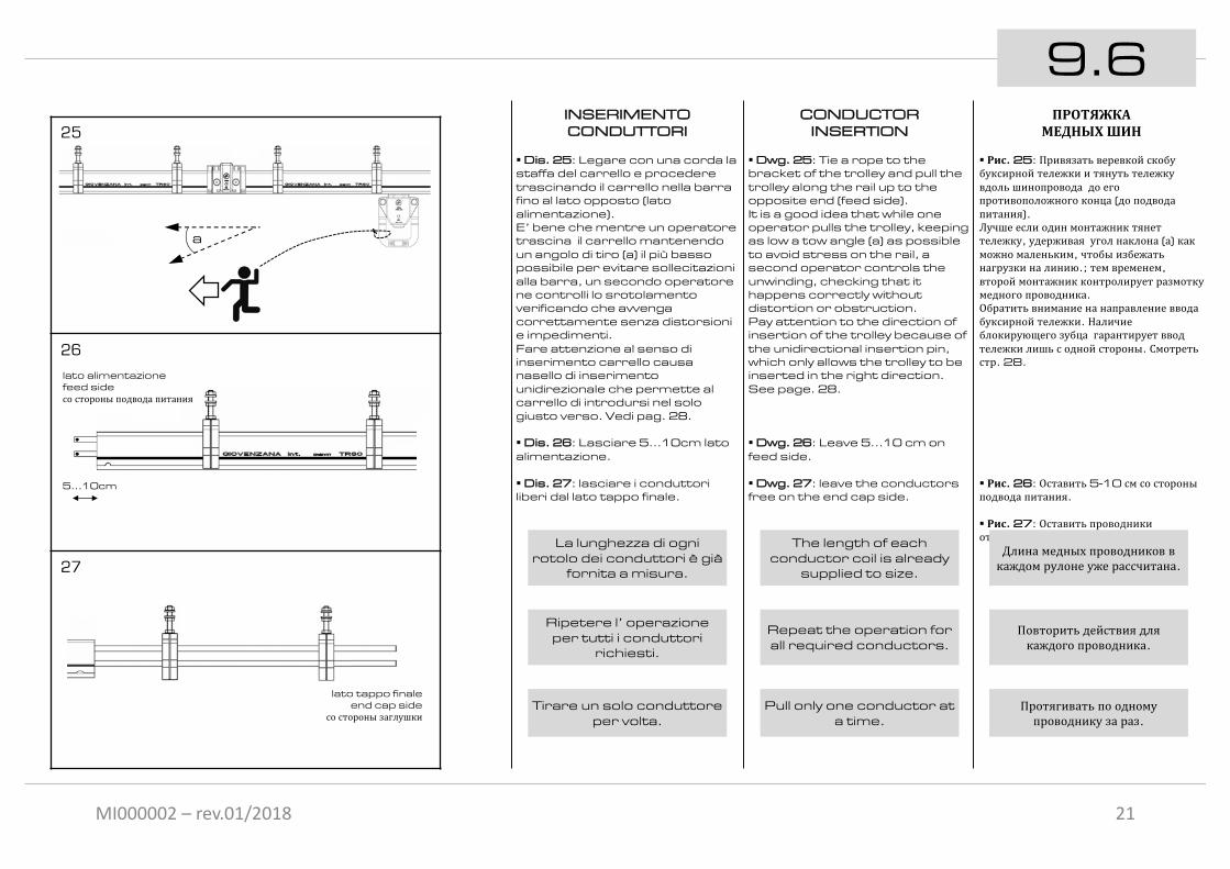
§ Dis. 25: Legare con una corda la staffa del carrello e procedere trascinando il carrello nella barra fino al lato opposto (lato alimentazione).E’ bene che mentre un operatore trascina il carrello mantenendo un angolo di tiro (a) il più basso possibile per evitare sollecitazioni alla barra, un secondo operatore ne controlli lo srotolamento verificando che avvenga correttamente senza distorsioni e impedimenti.Fare attenzione al senso di inserimento carrello causa nasello di inserimento unidirezionale che permette al carrello di introdursi nel solo giusto verso. Vedi pag. 28.
§ Dis. 26: Lasciare 5…10cm lato alimentazione.
§ Dis. 27: lasciare i conduttori liberi dal lato tappo finale.
Ripetere l’ operazione per tutti i conduttori
richiesti.
Tirare un solo conduttore per volta.
La lunghezza di ogni rotolo dei conduttori è già
fornita a misura.
21
9.6
a
lato alimentazionefeed sideсо стороны подвода питания
5…10cm
ПРОТЯЖКАМЕДНЫХШИН
§ Рис. 25: Привязать веревкой скобубуксирной тележки и тянуть тележкувдоль шинопровода до егопротивоположного конца (до подводапитания).Лучше если один монтажник тянеттележку, удерживая угол наклона (а) какможно маленьким, чтобы избежатьнагрузки на линию.; тем временем, второй монтажник контролирует размоткумедного проводника.Обратить внимание на направление вводабуксирной тележки. Наличиеблокирующего зубца гарантирует вводтележки лишь с одной стороны. Смотретьстр. 28.
§ Рис. 26: Оставить 5-10 см со стороныподвода питания.
§ Рис. 27: Оставить проводникиоткрытыми со стороны заглушки.
Длина медных проводников вкаждом рулоне уже рассчитана.
Повторить действия длякаждого проводника.
Протягивать по одномупроводнику за раз.
CONDUCTORINSERTION
§ Dwg. 25: Tie a rope to the bracket of the trolley and pull the trolley along the rail up to the opposite end (feed side).It is a good idea that while one operator pulls the trolley, keeping as low a tow angle (a) as possible to avoid stress on the rail, a second operator controls the unwinding, checking that it happens correctly without distortion or obstruction.Pay attention to the direction of insertion of the trolley because of the unidirectional insertion pin, which only allows the trolley to be inserted in the right direction. See page. 28.
§ Dwg. 26: Leave 5…10 cm on feed side.
§ Dwg. 27: leave the conductors free on the end cap side.
Repeat the operation for all required conductors.
Pull only one conductor at a time.
The length of each conductor coil is already
supplied to size.

MI000002 – rev.01/2018
INSERIMENTO CONDUTTORI
se presentealimentazione intermedia
§ Se presente una o più alimentazione intermedia occorre giuntare più spezzoni di conduttore fermandosi e ripartendo con l’ inserimento da ogni alimentazione intermedia.
§ L’ alimentazione intermedia solitamente è prevista per linee molto lunghe per ripristinare la caduta di tensione.
§ L ‘alimentazione intermedia si rende anche necessaria perche dopo una certa metratura di linea e a seconda della sezione conduttore, l’ inserimento del conduttore diventa molto difficoltoso per cui serve tagliare e ripartire inserendo un nuovo spezzone di conduttore.
§ In altri casi l’ alimentazione intermedia viene usata per prolungare una linea esistente come fosse un modulo di raccordo.
Per il montaggio dell’ alimentazione intermedia fare riferimento a pag. 33.
22
9.6CONDUCTOR
INSERTIONif in-line feed
Present
§ If there are one or more in-line feeds, it is necessary to join multiple conductor lengths, stopping and restarting conductor insertion at each in-line feed.
§ The in-line feed is usually provided for very long lines to restore voltage drop.
§ An in-line feed can also become necessary because after a certain length, and depending on the section of the conductor, conductor insertion can become quite difficult, and so it needs to be cut and insertion of a new length of conductor commenced.
§ In other cases, the in-line feed is used to extend an existing line, as if it was a connection module.
For mounting the in-line feed, please refer to page 33.
ПРОТЯЖКАМЕДНЫХШИН
при наличии линейногоподвода питания
§ При наличии одного или более линейныхподводов питания, необходимо соединятьотрезки проводников на каждом подводепитания, останавливаясь и начинаяпротяжку заново.
§ Линейные подводы питания обычнорассчитаны на очень длинные линии длявосстановления падений напряжения.
§ Линейные подводы питания также могутбыть необходимыми в случае трудностей спротяжкой проводников. В таких случаях, после достижения определенной длинылинии, проводник обрезается ипродолжает протягиваться, соединенныйлинейным подводом питания.
§ В других случаях, линейный подводпитания используется для продлениялинии в качестве соединительной детали.
Инструкции по монтажу линейногоподвода питания смотреть на стр. 33.

MI000002 – rev.01/2018
28
29
30
ALIMENTAZIONEDI TESTA
§ Dis. 28: mostra l’ alimentazione di testa.
§Rimuovere il coperchio sfilandolo verso l’alto e accedere al suo interno ove si trovano le viti fissaggio conduttori avvitate sui dadi co-stampati nella scocca.
§Rimuovere le viti fissaggio conduttori avvitati su ciascun dado prigioniero e le viti autofilettanti di fissaggio laterali.
§ Dis. 29: infilare il corpo alimentazione nella barra come mostrato in figura.
§ Dis. 30: munirsi di pinza e piegare l’ estremità del conduttore a 90° per circa 2cm come mostrato in figura.
TR6003
23
9.7
2 cm
HEADFEED
§ Dwg. 28: shows the head feed.
§Remove the cover by sliding it upwards to gain internal access to the conductor anchor screws, screwed into nuts co-moulded into the rail body.
§Remove the conductor anchor screws from each captive nut and the self-tapping side retaining screws.
§ Dwg. 29: insert the feed unit body onto the rail as shown in the figure.
§ Dwg. 30: bend approximately 2 cm of the end of the conductor by 90° with a pair of pliers, as shown in the figure.
КОНЦЕВОЙПОДВОД ПИТАНИЯ
§ Рис. 28: изображение концевогоподвода питания.
§Снять крышку, потянув ее вверх. Внутринаходятся винты для крепленияпроводников, привинченные наформованных в корпусе гайках.
§Снять крепежные винты дляпроводников и винты саморезы длябоковых креплений.
§ Рис. 29: Насадить корпус подводапитания как показано на рисунке.
§ Рис.30: с помощью плоскогубцевзагнуть (2 см) края проводников на 90°как показано на рисунке.

MI000002 – rev.01/2018
ALIMENTAZIONEDI TESTA
§ Dis. 31: far arretrare il corpo alimentazione di testa fino ad allinearsi con la barra.
§ Dis. 32: fissare il corpo alimentazione con le due viti laterali.
§ Dis. 33: procedere all’ inserimento dei conduttori nei prigionieri predisposti nel corpo alimentazione di testa:§ Simultaneamente un utente tira un conduttore per volta, l’ altro utente guida correttamente il conduttore fino ad infilarlo nel suo prigioniero corrispondente.
§ Ripetere l’ operazione per tutti i conduttori.
31
32
33
24
9.7
lato tappo finaleend cap side
со стороны заглушки
КОНЦЕВОЙПОДВОД ПИТАНИЯ
§ Рис. 31: придвинуть корпус подводапитания до упора.
§ Рис. 32: закрепить корпус подводапитания двумя боковыми винтами.
§ Рис. 33: вставить проводники вовстроенные внутри подвода питаниягайки-клипсы:§ Одновременно один монтажник тянет поочереди проводники со стороны заглушки, тем временем, другой монтажникнаправляет проводники всоответствующие гайки-клипсы.
§ Повторить действия для всехпроводников.
HEADFEED
§ Dwg. 31: pull back the head feed body until it is aligned with the rail.
§ Dwg. 32: secure the feed unit body with the two side screws.
§ Dwg. 33: proceed with insertion of conductors on the captive nuts provided in the head feed body:§ One conductor at a time is pulled by one operator, while the other operator simultaneously and correctly guides the conductor until it engages on its corresponding captive nut.
§ Repeat the operation for all conductors.

MI000002 – rev.01/2018
34
35
36
ALIMENTAZIONEDI TESTA
§ Dis. 34: allestire il cavo di alimentazione mediante capocorda ad anello.
§ Dis. 35: allentare il pressacavofino all’ apertura necessaria per infilare il cavo.Effettuare il cablaggio di ogni conduttore rispettando la loro propria funzione quindi fissare ogni conduttore con le viti fornite.Completare il cablaggio serrando il pressacavo.
§ Dis. 36: completare la chiusura con il coperchio inserendolo dall’ alto come indicato.
Min Ø 6mm
Diametro interno capocorda minimo: 6 mm
Ricontrollare il cablaggio e assicurarsi che
nessuno e in nessun caso la linea possa venire
anche accidentalmente messa in tensione
ATTENZIONE:la posizione del
conduttore di terra identificato con la linea continua nera esterna
La linea deve essere opportunamente
protetta sia da sovraccarichi e
cortocircuiti sia da dispersioni di corrente
verso terra
!
25
9.7
Click!
HEADFEED
§ Dwg. 34: prepare the power feed cable with ring terminal lugs.
§ Dwg. 35: loosen the cable gland until the opening is sufficient to insert the cable.Carry out the wiring of each conductor, respecting their function, and then anchor each conductor with the screws provided.Complete the wiring by tightening the cable gland.
§ Dwg. 36: complete closure by fitting the cover, sliding it down from above as indicated.
Terminal lug minimum internal diameter: 6 mm
Recheck the wiring and ensure that under no
circumstances can the line be powered up, even
accidentally.
WARNING:the position of the earth conductor is identified by the external continuous
black line
The line must be opportunely protected against both overloads and short circuits and
from earth leakage current
КОНЦЕВОЙПОДВОД ПИТАНИЯ
§ Рис. 34: оснастить кабель питаниякабельными наконечниками.
§ Рис.35: ослабить сальник до нужногодля ввода кабеля открытия.Подсоединить каждый проводник, сохраняя последовательность, и закрепитькаждый проводник предоставленнымивинтами. После подсоединения зажать сальник .
§ Рис. 36: в конце, закрыть крышку какуказано на рисунке.
Минимальный диаметрвнутреннего отверстия
кабельного наконечника : 6мм
ВНИМАНИЕ:расположение проводниказаземление указано чернойсплошной линией на боковой
стороне шинопровода
Проверить подсоединениепроводников и убедиться, чтолиния ни в коем случае не
находится под напряжением.
Линия должна бытьсвоевременно защищена отперенапряжения и короткогозамыкания, а также от утечки
тока на землю

MI000002 – rev.01/2018
MONTAGGIOULTIMA BARRA
§ Dis. 37: tagliare a misura il rame eccedente: deve essere piu corto di 5…10cm dell’ ultima barra.
I conduttori non devono essere tagliati a filo dell’ ultima barra perché in questo modo non avrebbero spazio per la loro normale dilatazione.
§ Dis. 38: infilare l’ ultima barra guidando i conduttori nelle apposite sedi e facendolo scorrere dentro le sospensioni.
37
38
26
9.8
5…10cm
MOUNTINGLAST RAIL
§ Dwg. 37: cut off excess copper to size: it must be di 5-10 cm shorter than the last rail.
The conductors must not be cut flush with the last rail because they would not have space for their normal expansion.
§ Dwg. 38: Insert the last rail, guiding the conductors in the seats provided, and slide it through the hangers.
МОНТАЖ ПОСЛЕДНЕЙ СЕКЦИИШИНОПРОВОДА
§ Рис. 37: отрезать излишек меднойшины. Шина должна быть короче секциина 5-10 см.
Проводники не должны быть срезанывровень с последней секцией, чтобыосталось место для их расширения.
§ Рис. 38: протянуть последнюю секциюшинопровода внутри подвесных скоб, вставив проводники в соответствующиевыемки,

MI000002 – rev.01/2018
39
40
41
27
25ATR6004TR6005
9.9CARRELLI
§ Dis. 39: mostra il carrello.
Esistono due versioni:
§TR6004: portata 25A 4poli§TR6005: portata 25A 5poli
Il cavo elettrico NON è fornito per cui occorre procedere al sua cablaggio, come indicato inDis. 40 e in Dis. 41:
§ Dis. 40: tagliare il gommino a misura sezione cavo utilizzato.
§ Dis. 41: svitare la vite di ritenuta e rimuovere il coperchio morsetti.§Effettuare il cablaggio di ogni conduttore rispettando la loro proprie funzione.
§Rimontare il coperchio morsetti e serrare la vite
ATTENZIONE:Tutti i conduttori sono
chiaramente identificati sia sul morsetto sia in
prossimità della relativa spazzola conduttrice.
Il conduttore di terra è ancora meglio identificato
da un etichetta gialla aggiuntiva
“CHECK GRUOND POSITION”
In modo da evitare qualsiasi errore di
cablaggio. Il conduttore di terra dovrà essere
allineato alla linea continua nera presente
sulla barra.
TROLLEYS
§ Dwg. 39: shows trolley.
There are two versions:
§TR6004: 25A capacity - 4 poles§TR6005: 25A capacity - 5 poles
The electric cable is NOT provided, and so needs to be wired, as indicated inDwgs. 40 and 41:
§ Dwg. 40: cut the rubber grommet to the size of the cable used.
§ Dwg. 41: unscrew the retaining screw and remove the terminal cover.§ Carry out the wiring of each conductor, respecting their function.
§ Replace the terminal cover and tighten the screw.
WARNING:All the conductors are
clearly identified, both on the terminal and near to the relevant conductor
shoe.The earth conductor is further identified by an
additional yellow tag: “CHECK GROUND
POSITION”In order to avoid any
wiring error, the earth conductor must be
aligned with the continuous black line on
the rail.
ТОКОСЪЕМНИКИ
§ Рис. 39: изображение токосъемника
Существуют два вида:
§TR6004: на 25 А, 4 проводника§TR6005: на 25 А, 5 проводников
Электрический кабель НЕ входит вкомплект, поэтому необходимоприступить к проводке, как указано наРис. 40 и Рис.41:
§ Рис. 40: обрезать резиновую втулку подразмер используемого кабеля.
§ Рис. 41: отвинтить крепежный винт иснять крышку клеммной коробки.Подсоединить каждый проводник , соблюдая последовательность.
§Закрыть крышку клеммной коробки изатянуть винты.
ВНИМАНИЕ:Все проводники четко
отмечены, как на клеммах таки в непосредственной
близости от соответственнойпроводящей щетки.Во избежание ошибокпроводки заземляющийпроводник отмечен
дополнительной желтойэтикеткой “ПРОВЕРКА
ПОЛОЖЕНИЯ ЗАЗЕМЛЕНИЯ”. Проводник заземления
должен быть выровнен сосплошной черной линией набоковой стороне секции
шинопровода.

MI000002 – rev.01/2018
42
43
44
28
TR6007
Ø13 mm
Ø16 mm
13mm
end capside
one-wayinsertion pin
9.9CARRELLI
§ Dis. 42: a seconda delle applicazioni viene fornita anche la staffa braccio di traino TR6007 completa di due gaffettefermacavo: Ø13 e Ø16 mm.
§ Dis. 43: mostra come assemblare la staffa braccio di traino al carrello.
§ Dis. 44: inserimento carrello:§Prestare attenzione al nasello di fermo del carrello che deve posizionarsi nel profilo cavo della barra poiché se inserito nel modo errato il nasello si scontrerà con profilo di fermo della barra impedendone l’ inserimento.
§per l’ inserimento del carrello premere le spazzole quindi guidarlo fino al completo inserimento.
ATTENZIONE:Tutti i conduttori sono
chiaramente identificati sia sul morsetto sia in
prossimità della relativa spazzola conduttrice.
Il conduttore di terra è ancora meglio identificato
da un etichetta gialla aggiuntiva
“CHECK GRUOND POSITION”
In modo da evitare qualsiasi errore di
cablaggio. Il conduttore di terra dovrà essere
allineato alla linea continua nera presente
sulla barra.
ТОКОСЪЕМНИКИ
§ Рис. 42: в зависимости от применения, поставляется с буксирной скобойTR6007 в комплекте с двумя зажимамидля кабеля: 13 и 16 мм.
§ Рис. 43: показывает как подсоединитьбуксирную скобу к токосъемнику.
§ Рис. 44: вставка токосъемника:§Обратите внимание на блокирующийзубец на токосъемнике, который долженбыть расположен в полой выемке секции. При неправильной установке , зубецтокосъемника столкнется с профилемсекции, предотвращая тем самымустановку.
§Для установки токосъемника, надавитьна щетки и толкать до полного ввода.
ВНИМАНИЕ:Все проводники четко
отмечены, как на клеммах таки в непосредственной
близости от соответственнойпроводящей щетки.Во избежание ошибокпроводки заземляющийпроводник отмечен
дополнительной желтойэтикеткой “ПРОВЕРКА
ПОЛОЖЕНИЯ ЗАЗЕМЛЕНИЯ”. Проводник заземления
должен быть выровнен сосплошной черной линией набоковой стороне секции
шинопровода.
TROLLEYS
§ Dwg. 42: depending on the application, a TR6007 towing arm bracket may also be supplied, complete with two cable clips: Ø13 mm and Ø16 mm.
§ Dwg. 43: shows how to mount the towing arm bracket on the trolley.
§ Dwg. 44: trolley insertion:§Pay attention to the trolley’s stop pin, which must be positioned in the rail’s hollow profile, because if incorrectly inserted the pin will strike the rail’s stop profile, preventing insertion.
§to insert the trolley, press on the shoes and then guide it in until it is fully inserted.
WARNING:All the conductors are
clearly identified, both on the terminal and near to the relevant conductor
shoe.The earth conductor is further identified by an
additional yellow tag: “CHECK GROUND
POSITION”In order to avoid any
wiring error, the earth conductor must be
aligned with the continuous black line on
the rail.

MI000002 – rev.01/2018
45
46
47
29
9.10
TR6013
13mm
STAFFA DOPPIO CARRELLO
§ Dis. 45: mostra la staffa doppio carrello usata per connettere in parallelo due carrelli.
§ Dis. 46: assemblare entrambi i carrelli sulla staffa come indicato in disegno (*).
§ Dis. 47: cablare i cavi a misura opportuna e collegare entrambi i carrelli connettendoli alla scatola portafrutti della staffa.
Fare attenzione a cablare correttamente tutti i
rispetti conduttori dei carrelli nello stesso
morsetto della scatola
ATTENZIONE:POSIZIONARE
ENTRAMBI I CARRELLI NELLO STESSO VERSO
tenendo come riferimento la spazzola del conduttore di terra altresì identificato sulla
barra con la linea continua nera esterna.
Il nasello di fermo di entrambi i carrelli viene
quindi a trovarsi dalla stessa parte
(*) montaggio consigliato, altre configurazioni montaggio possibili e
con o senza bussola purché il sistema non interferisca con la linea
ПОВОДОК ДВОЙНОГОТОКОСЪЕМНИКА
§ Рис. 45: изображение поводка двойноготокосъемника, который используется дляпараллельного подсоединения двухтокосъемников.
§ Рис. 46: установить оба токосъемникана поводок как описано на рисунке (*).
§ Рис. 47: провести кабели нужногоразмера и подсоединить обатокосъемника, подключив их краспределительной коробке поводка.
(*) Рекомендуемый монтаж. Возможныдругие способы монтажа, при условие если
не будет помех для линии.
ВНИМАНИЕ:РАЗМЕСТИТЬ ТОКОСЪЕМНИКИ ВОДНОМ НАПРАВЛЕНИИ, принимаяза ориентир щетку заземляющего
проводника, отмеченную на
боковой стороне секциишинопровода сплошной черной
линией.
Будьте внимательны, чтобыправильно подсоединить всесоответствующие проводники
токосъемников в своихклеммных коробках.
DOUBLE-TROLLEY SUPPORT
§ Dwg. 45: shows the double-trolley support used to connect two trolleys in parallel.
§ Dwg. 46: mount both trolleys on the support as shown in the drawing (*).
§ Dwg. 47: wire cables of opportune length and connect both of the trolleys, connecting them to the socket box of the bracket.
(*) recommended installation - other installation configurations possible, with or without bushes, as long as
system does not interfere with line.
WARNING:POSITION BOTH
TROLLEYS IN THE SAME DIRECTION with
reference to the shoe of the earth conductor, also
identified on the rail by the external continuous
black line.
The stop pin of both trolleys is therefore on
the same side
Take care to correctly wire all the respective
conductors of the trolleys to the same terminal in the box
Блокирующий зубец на обоихтокосъемниках должен
находится с одной стороны

MI000002 – rev.01/2018
48
49
50
INSERIMENTO GUARNIZIONE
ECHIUSURA LINEA
§ Dis. 48: se previsto inserire la guarnizione nel labbro inferiore rivolta come indicato in disegno in modo che entrambe le parti poi vadano a chiudere il profilo limitando così l’ accesso a polvere.
§ Dis. 49: assemblare il tappo di chiusura come indicato in disegno stringendo le due viti laterali.
§ Dis. 50: mostra la corretta chiusura della barra.
30
9.11
TR6006
TR6012
SEALING STRIP INSERTION
ANDLINE TERMINATION
§ Dwg. 48: if applicable, insert the sealing strip in the lower lip oriented as shown in the drawing so that both parts seal the profile to limit the entry of dust.
§ Dwg. 49: mount the end cap as shown in the drawing and tighten the two side screws.
§ Dwg. 50: shows correct rail termination.
ВСТАВКАУПЛОТНИТЕЛЬНОЙ ЛЕНТЫ
ИЗАКРЫТИЕ ЛИНИИ
§ Рис. 48: если предусмотрено, вставитьуплотнительную ленту в нижнюю выемкукак указано на рисунке, таким образом, чтобы обе части закрывали шинопроводснизу, тем самым ограничивая доступпыли.
§ Рис. 49: смонтировать заглушку какуказано на рисунке, закрутив боковыевинты.
§ Рис. 50: изображение правильногозакрытия секции.

MI000002 – rev.01/2018
51
52
TR8510
31
Max50x50 mm
10
13mm
Ø9 mm
BRACCIO DI TRAINO
§ Dis. 51: mostra il braccio di traino.
§ Dis. 52: deve essere montato sul braccio di trascinamento previsto sull’ apparecchio mobile come mostrato in dis. 52.
Il braccio di trascinamento dell’ apparecchio mobile solitamente è un tubolare quadro e le dimensioni massime accettata dal braccio di traino sono 50x50mm.
БУКСИРНАЯ ОПОРА
§ Рис. 51: изображение буксирнойопоры.
§ Рис. 52: буксирная опора должна бытьустановлена на направляющую деталь, предусмотренную на передвижномустройстве как показано на рис. 52.
Направляющая деталь обычнопредставляет собой трубчатый каркас, максимальный размер которого можетдостигать 50х50мм.
TOWING ARM
§ Dwg. 51: shows the towing arm.
§ Dwg. 52: must be mounted on the tow arm provided on the mobile device as shown in Dwg. 52.
The tow arm of the mobile device is usually a square tube and the maximum size accepted by the towing arm is 50x50 mm.

MI000002 – rev.01/2018
53
54
55
= =
32
= =
= =
= =
= =
10
Dis. 54: assicurarsi che il percorso del dispositivo
mobile sia parallelo ( // ) al percorso del carrello
evitando lo sfilamento del braccio di traino oppure
la collisione del dispositivo mobile con il carrello
oppure la linea stessa.
!
Dis. 55: il braccio di traino deve essere libero di
scorrere sia in verticale che lateralmente, è quindi
vietato bloccare il suo movimento con
saldature, legami ecc …
!
BRACCIO DI TRAINO
§ Dis. 53: Prestare attenzione a regolare il braccio di trascinamento del dispositivo mobile finché le estremità del braccio di traino andranno a posizionarsi circa a metà sia in senso verticale che in senso laterale sulla staffa braccio di traino in caso di carrello semplice oppure nella staffa metallica sopra la cassetta portafrutti se in presenza della staffa doppio carrello.
Dwg. 54: ensure that the path of the mobile device
is parallel ( // ) to the path of the trolley, to avoid the towing arm slipping off or
collision of the mobile device with the trolley or
the line itself.
Dwg. 55: the towing arm must be free to slide both
vertically and sideways, and so it is prohibited to block its movement by
welding, ties, etc.
TOWING ARM
§ Dwg. 53: Pay attention to adjust the tow arm of the mobile device so that the ends of the towing arm will be positioned approximately halfway in both the sideways and vertical directions on the towing arm bracket, in the case of simple trolley, or on the metal support above the socket box in the case of the double-trolley support.
БУКСИРНАЯ ОПОРА
§ Рис. 53: внимательно отрегулироватьнаправляющую деталь на передвижномустройстве, так чтобы буксирная опорабыла расположена посередине (повертикали и горизонтали) буксирнойскобы в случае обычного токосъемника, инад распределительной коробкой наповодке для сдвоенного токосъемника.
Рис. 54: убедиться, чтодвижение передвижного
устройство параллельно (//) движению токосъемника,
избегая при этомсоскальзывание буксирнойопоры или столкновениепередвижного устройства стокосъемником или с самим
шинопроводом.
Рис. 55: буксирная опорадолжна свободно скользитьвверх-вниз и в стороны, поэтому категорически
запрещено ее фиксироватьпосредством сварки, узлов и
т.д.

MI000002 – rev.01/2018
56
57
58
ALIMENTAZIONE INTERMEDIA
§ Dis. 56: mostra l’ alimentazione intermedia fornita con pressacavo M25 sciolto nell’ imballo.
§ Dis. 57: Scegliere la posizione ideale del pressacavo tra le 5+5 possibili ubicazioni (su i due lati della scatola) quindi rompere la relativa chiusura prefratturata ed eseguire il montaggio del pressacavo.
Infilare i due semigusci nelle barre.
§ Dis. 58: Nel punto ove andrà a posizionarsi l’ alimentazione intermedia occorre piegare tutti i conduttori di 90° per una lunghezza di circa 3cm quindi riavvicinare le barre.
3 cm
33
TR6008
11IN-LINE
FEED
§ Dwg. 56: shows the in-line feed supplied with a loose M25 cable gland in the package.
§ Dwg. 57: Select the ideal position for the cable gland from the 5+5 possible locations (on the two sides of the box), then knock out the relevant pre-cut cover and mount the cable gland.
Insert the two half-shells on the rails.
§ Dwg. 58: At the point where the in-line feed will be positioned, all the conductors must be bent by 90°for a length of approximately 3 cm and then the rails moved together again.
ЛИНЕЙНЫЙ ПОДВОД ПИТАНИЯ
§ Рис. 56: изображение линейногоподвода питания, в комплекте ссальником (кабельным вводом) М25 вупаковке.
§ Рис. 57: выбрать подходящееположение кабеля из 5+5 возможныхвариантов (по обеим сторонам короба), выдавить нужное окошко и установитьсальник как указано на рисунке.
Продеть обе половинки короба нашинопровод.
§ Рис.58: в месте расположениялинейного подвода питания необходимозагнуть все проводники на 3 см в 90° и соединить части шинопровода.

MI000002 – rev.01/2018
ALIMENTAZIONE INTERMEDIA
§ Dis. 59: forare i conduttori e allestire il cavo di alimentazione con appositi capocorda ad occhiello e infine serrare i conduttori e il capocorda con una vite e dado adeguato (cons. M5 flangiato).§ Dis. 60: altrimenti è possibile serrare conduttori e cavo con morsetto TR6015 (occorre comunque forare i conduttori).
§ Dis. 61: completare la chiusura e il fissaggio dell’ alimentazione intermedia.§Serrare il pressacavo.
59
60
61 Ricontrollare il cablaggio e assicurarsi che
nessuno e in nessun caso la linea possa venire
anche accidentalmente messa in tensione
ATTENZIONE:la posizione del
conduttore di terra è identificata con la linea continua nera esterna
La linea deve essere opportunamente
protetta sia da sovraccarichi e
cortocircuiti sia da dispersioni di corrente
verso terra
!
Allineare i conduttori per evitare l’ usura precoce delle spazzole carrelli e
evitare microinterruzioni di corrente
34
11
Click!
TR6015
IN-LINEFEED
§ Dwg. 59: drill holes in the conductors, prepare the power feed cable with suitable ring terminal lugs and, lastly, tighten the conductors and terminal lugs with appropriate screws and nuts (flanged M5 recommended).§ Dwg. 60: otherwise it is possible to tighten conductors and cable with TR6015 terminal clamps (it is still necessary to drill holes in the conductors).
§ Dwg. 61: complete closure and fastening of the in-line feed.
§Tighten cable gland.
Recheck the wiring and ensure that under no
circumstances can the line be powered up, even
accidentally.
WARNING:the position of the earth conductor is identified by the external continuous
black line
The line must be opportunely protected against both overloads and short circuits and
from earth leakage current
Align the conductors to avoid premature wear on trolley shoes and current
micro-interruptions.
ЛИНЕЙНЫЙ ПОДВОД ПИТАНИЯ
§ Рис. 59: просверлить концыпроводников и оснастить кабель питаниякабельными наконечниками. Подсоединить проводники к кабельнымнаконечникам подходящими винтами сгайками ( рекомендуется фланцевый М5).
§ Рис. 60: в качестве альтернативыможно использовать стыковочные зажимыTR6015 (в любом случае проводникинеобходимо просверлить).
§ Рис. 61: завершить крепление изакрыть линейный подвод питания.
§Затянуть сальник.
Во избежаниепреждевременного износащеток токосъемника и
прерываний подачи тока, выровняйте проводники.
ВНИМАНИЕ:расположение проводниказаземление указано чернойсплошной линией на боковой
стороне шинопровода
Проверить подсоединениепроводников и убедиться, чтолиния ни в коем случае не
находиться под напряжением
Линия должна бытьсвоевременно защищена отперенапряжения и короткогозамыкания, а также от утечки
тока на землю

MI000002 – rev.01/2018
62
63
64
PROLUNGAMENTO DIUNA LINEA ESISTENTE
A seconda della personalizzazione esistono diversi modi, qui riportato il più comune e semplice:
§ Dis. 62-63: Estrarre il tappo finale e rimuovere l’ ultima barra.
§ Dis. 64: Tagliare l’ ultima barra rimossa in modo tale da lasciare circa 2…3cm di conduttore sporgente, quindi rimontare l ‘ultima barra.
.
35
2…3cm
12
TR6006
EXTENSION OF AN EXISTING LINE
There are various methods, depending on the personalization - the more common and simpler ones are indicated below:
§ Dwgs. 62-63: Extract the end cap and remove the last rail.
§ Dwg. 64: Cut the last rail removed so as to leave approximately 2-3 cm of conductor protruding, and then remount the last rail.
.
ПРОДЛЕНИЕЛИНИИ
В зависимости от индивидуальныхнастроек, существуют разные способыпродления линии. В данном пособииописан самый распространенный ипростой.
§ Рис. 62-63: Снять заглушку иотсоединить последнюю секцию.
§ Рис. 64: Отрезать часть снятой секции, чтобы проводники выступали на 2-3 см, после чего заново смонтировать секции.

MI000002 – rev.01/2018
65
66
67
TR6008
2 cm
TR6001
PROLUNGAMENTO DIUNA LINEA ESISTENTE
§ Dis. 65: Piegare i conduttori a 90° quindi forarlo.
§ Aggiungere le barre di prolungamento linea quindi inserire i conduttori e infine piegarli a 90° e forarli.
§ Connettere i conduttori con una vite e dado opportuno altrimenti è possibile serrare conduttori e cavo con morsetto TR6015 (occorre comunque forare i conduttori).
§ Dis. 66: Se il prolungamento non è tale da provocare cadute di tensione è possibile usare una giunzione TR6001 oppure una alimentazione intermedia TR6008 senza alimentarla e senza montare il pressacavo.Mentre se il prolungamento della linea è tale da provocare cadute di tensione è necessario utilizzare un’ alimentazione intermedia regolarmente connessa alla rete di alimentazione.
§ Dis. 67: completare la chiusura della congiunzione (in dis. rappresentata variante di chiusura con giunzione TR6001, per la variante chiusura con alimentazione intermedia TR6008 fare riferimento a dis. pag. 33).
Allineare i conduttori per evitare l’ usura precoce delle spazzole carrelli e
evitare microinterruzioni di corrente
36
12
Click!
EXTENSION OF AN EXISTING LINE
§ Dwg. 65: Bend the conductors by 90° and then drill hole.
§ Add the line extension rails, then insert the conductors and, finally, bend them by 90° and drill holes in them.
§ Connect the conductors with a suitable nut and screw -otherwise it is possible to tighten conductors and cable with TR6015 terminal clamps (it is still necessary to drill holes in the conductors).
§ Dwg. 66: If the extension is such that it does not cause voltage drops, it is possible to use a TR6001 joint or a TR6008 in-line feed without supplying power and without mounting the cable gland.While if the line extension is such as to cause voltage drops, it is necessary to use an in-line feed regularly connected to the power supply network.
§ Dwg. 67: complete joint closure (closure variant with TR6001 joint shown in drawing - for the closure variant with TR6008 in-line feed, please refer to drawing on page 33).
Align the conductors to avoid premature wear on trolley shoes and current
micro-interruptions.
ПРОДЛЕНИЕЛИНИИ
§ Рис. 65: Загнуть проводники на 90° и просверлить.
§ Добавить нужное количество секций для продления линии и протянуть проводники. В конце загнуть их на 90° и просверлить.
§ Подсоединить проводники с помощью подходящих винтов и гаек или стыковочных зажимов TR6015 (в любом случае необходимо просверлить проводники).
§ Рис. 66 : Если продление не достаточно длинное, чтобы вызвать падение напряжения, можно использовать соединительную муфту TR6001 или линейный подвод питания TR6008 без проводки и без сальника. Если же продление линии может вызвать падение напряжения, необходимо использовать линейный подвод питания, подключенный к сети питания.
§ Рис. 67 : завершить закрытие соединения (на рис. представлен вариант закрытия с соединительной муфтой TR6001; для варианта с подводом питания TR6008 смотреть стр. 33).
Во избежаниепреждевременного износащеток токосъемника и
прерываний подачи тока, выровняйте проводники.

MI000002 – rev.01/2018
13
37
La linea di alimentazioneTR60 è“for life - senza manutenzione” ma occorre tuttavia controllare periodicamente, con scadenze a seconda dell’ utilizzo , della lunghezza linea e dell’ambiente di esercizio, il suo regolare funzionamento:
§ Controllare visivamente tutta la linea ed accertarsi dell’ assenza di rotture da impatto.
§ Verificare che la linea sia saldamente fissata in posizione controllando il corretto serraggio delle sospensioni e giunzioni.
§ Controllare che dal pressacavo/i non ci siano infiltrazioni d’acqua e che la gomma del pressacavo di tenuta sia integra ed elastica.
§ Verificare lo scorrimento del carrello/i per l’ intero sviluppo della linea.
§ Rimuovere il carrello e controllare lo stato delle spazzole e se consumate eccessivamente procedere alla loro sostituzione o all’ intera sostituzione del carrello/i. Controllare quindi anche l’ usura dei conduttori.
§ Controllare la regolazione e il serraggio del braccio/staffa di traino.
The TR60 busbar line is “maintenance-free - for life”, but it is still necessary to periodically check its regular functioning with a frequency according to usage, line length and operating environment, as follows:
§ Visually check the entire line and make sure there is no impact damage.
§ Check that the line is firmly fixed in position, controlling the correct tightening of the hangers and joints.
§ Check that there is no water infiltration through the cable gland(s) and that the rubber of the cable gland seal is intact and elastic.
§ Check the running of the trolley(s) for the entire length of the line.
§ Remove the trolley and check the condition of the shoes and, if excessively worn, replace them or replace the complete trolley(s). Afterwards, also check for wear on the conductors.
§ Check the adjustment and tightening of the towing arm/bracket.
Шинопроводные троллеи TR60 нетребуют обслуживания, но все жестоит периодически проверятьисправность их работы, свременными рамками зависящимиот использования длины линии иокружающей среды эксплуатации:
§ Проверить визуально нацелостность линии и убедиться вотсутствии поломок от ударов.
§ Убедиться в том, что линия крепкозафиксирована. Проверитьправильность крепления подвесныхопор и муфт.
§ Проверить сальник/и на отсутствиепроникновения жидкости, на егоцелостность и эластичность.
§ Проверить скольжениетокосъемника/ов по всей длинелинии.
§ Снять токосъемник и проверитьсостояние щеток: в случае сильногоизноса их необходимо заменить илизаменить весь токосъемник. Затемпроверить на износ проводники.
§Проконтролировать настройку икрепление буксирнойопоры/поводка.
MANUTENZIONE
MAINTENANCE
Техническоеобслуживание

MI000002 – rev.01/2018
14
38
Risoluzione dei problemi:
§ Problema: Non riesco ad inserire il carrello oppure sono riuscito ad inserire il carrello ma non scorre libero e si blocca.
Causa: il carrello è stato inserito nel senso errato
Soluzione: rimuovere il carrello e inserirlo nella direzione giusta facendo attenzione al nasello di blocco unidirezionale.
§ Problema: Il carrello ha spesso dei falsi contatti.
Causa: spazzole consumate eccessivamente o non aderiscono bene ai conduttori.
Soluzione: verificare lo stato delle spazzole e assicurarsi che le molle siano integre.
§ Problema: Ho montato la linea ma appena applico tensione scatta l’ interruttore magneto-termicodifferenziale di protezione linea.
Causa: sovraccarico - cortocircuito oppure dispersione di corrente verso terra.
Soluzione: ricontrollare tutti i cablaggi dell’ alimentazione/i, del giunto/i di sezionamento (se previsto) e di tutti i carrelli ricontrollandone anche l’ esatto senso di inserimento.
Решение проблем:
§ Проблема: Не могу вставить токосъемник или вставилтокосъемник, но он не скользит свободно или застревает.
Причина: токосъемник вставлен с неправильной стороны.
Решение: снять токосъемник и вставить его с правильнойстороны, обратив внимание на односторонний блокирующийзубец.
§ Проблема: токосъемник часто плохо соединяется с линией.
Причина: щетки чрезмерно изношены или неплотно прилегаютк проводникам.
Решение: проверить состояние щеток и убедится, что пружиныне повреждены.
§ Проблема: Линия установлена, но как только подаетсянапряжение, срабатывает автоматический выключательдифференциальной защиты линии.
Причина: перегрузка – короткое замыкание или утечка тока наземлю.
Решение: перепроверить всю проводку подвода/ов питания, изолирующей секции (если таковая имеется) и также всехтокосъемников, перепроверив заодно правильно ли онивставлены.
Troubleshooting:
§ Problem: I cannot insert the trolley or managed to insert the trolley but it doesn't run smoothly and jams.
Cause: the trolley has been inserted in the wrong direction.
Solution: remove the trolley and insert it in the right direction, paying attention to the unidirectional stop pin.
§ Problem: The trolley often has bad contact problems.
Cause: shoes excessively worn or do not make good contact with the conductors.
Solution: check condition of the shoes and ensure that the springs are intact.
§ Problem: I installed the line, but as soon as power is applied, the thermal-magnetic residual-current circuit breaker for line protection is triggered.
Cause: overload, short circuit, or current leakage to earth.
Solution: recheck all the wiring of the feed(s), the insulating joint (if applicable) and all the trolleys, also double-checking the correct direction of insertion.<
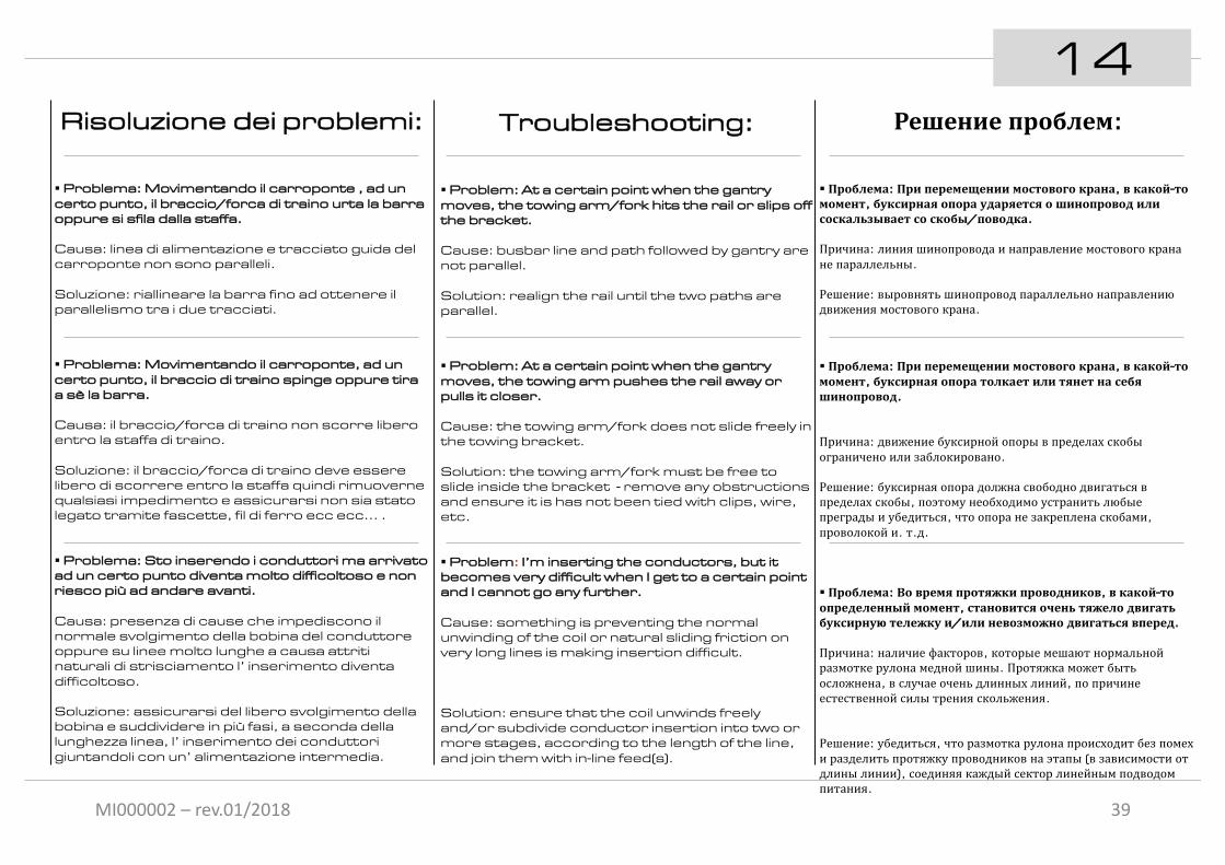
MI000002 – rev.01/2018
14
39
Risoluzione dei problemi:
§ Problema: Movimentando il carroponte , ad un certo punto, il braccio/forca di traino urta la barra oppure si sfila dalla staffa.
Causa: linea di alimentazione e tracciato guida del carroponte non sono paralleli.
Soluzione: riallineare la barra fino ad ottenere il parallelismo tra i due tracciati.
§ Problema: Movimentando il carroponte, ad un certo punto, il braccio di traino spinge oppure tira a sè la barra.
Causa: il braccio/forca di traino non scorre libero entro la staffa di traino.
Soluzione: il braccio/forca di traino deve essere libero di scorrere entro la staffa quindi rimuoverne qualsiasi impedimento e assicurarsi non sia stato legato tramite fascette, fil di ferro ecc ecc… .
§ Problema: Sto inserendo i conduttori ma arrivato ad un certo punto diventa molto difficoltoso e non riesco più ad andare avanti.
Causa: presenza di cause che impediscono il normale svolgimento della bobina del conduttore oppure su linee molto lunghe a causa attriti naturali di strisciamento l’ inserimento diventa difficoltoso.
Soluzione: assicurarsi del libero svolgimento della bobina e suddividere in più fasi, a seconda della lunghezza linea, l’ inserimento dei conduttori giuntandoli con un’ alimentazione intermedia.
Troubleshooting:
§ Problem: At a certain point when the gantry moves, the towing arm/fork hits the rail or slips off the bracket.
Cause: busbar line and path followed by gantry are not parallel.
Solution: realign the rail until the two paths are parallel.
§ Problem: At a certain point when the gantry moves, the towing arm pushes the rail away or pulls it closer.
Cause: the towing arm/fork does not slide freely in the towing bracket.
Solution: the towing arm/fork must be free to slide inside the bracket - remove any obstructions and ensure it is has not been tied with clips, wire, etc.
§ Problem: I’m inserting the conductors, but it becomes very difficult when I get to a certain point and I cannot go any further.
Cause: something is preventing the normal unwinding of the coil or natural sliding friction on very long lines is making insertion difficult.
Solution: ensure that the coil unwinds freely and/or subdivide conductor insertion into two or more stages, according to the length of the line, and join them with in-line feed(s).
Решение проблем:
§ Проблема: При перемещении мостового крана, в какой-томомент, буксирная опора ударяется о шинопровод илисоскальзывает со скобы/поводка.
Причина: линия шинопровода и направление мостового кранане параллельны.
Решение: выровнять шинопровод параллельно направлениюдвижения мостового крана.
§ Проблема: При перемещении мостового крана, в какой-томомент, буксирная опора толкает или тянет на себяшинопровод.
Причина: движение буксирной опоры в пределах скобыограничено или заблокировано.
Решение: буксирная опора должна свободно двигаться впределах скобы, поэтому необходимо устранить любыепреграды и убедиться, что опора не закреплена скобами, проволокой и. т.д.
§ Проблема: Во время протяжки проводников, в какой-тоопределенный момент, становится очень тяжело двигатьбуксирную тележку и/или невозможно двигаться вперед.
Причина: наличие факторов, которые мешают нормальнойразмотке рулона медной шины. Протяжка может бытьосложнена, в случае очень длинных линий, по причинеестественной силы трения скольжения.
Решение: убедиться, что размотка рулона происходит без помехи разделить протяжку проводников на этапы (в зависимости отдлины линии), соединяя каждый сектор линейным подводомпитания.

MI000002 – rev.01/2018
Note / Notes / Заметки
40

MI000002 – rev.01/2018
Note / Notes / Заметки
41

www.giovenzana.comMI000002 – rev.01/2018