tÜrk standardi - regbar.com.tr
TRANSCRIPT

TÜRK STANDARDITURKISH STANDARD
TS EN 1536:2010 Ocak 2011
ICS 93.020
ÖZEL JEOTEKNİK UYGULAMALAR DELME (FORE)- KAZIKLAR- (YERİNDE DÖKME BETONARME KAZIKLAR
Execution of special geotechnical work - Bored piles
TS EN 1536 (2011) standardı, EN 1536 (2010) standardı ile birebir aynı olup, Avrupa Standardizasyon Komitesi’nin (CEN, Avenue Marnix 17 B-1000 Brussels) izniyle basılmıştır. Avrupa Standardlarının herhangi bir şekilde ve herhangi bir yolla tüm kullanım hakları Avrupa Standardizasyon Komitesi (CEN) ve üye ülkelerine aittir. TSE kanalıyla CEN’den yazılı izin alınmaksızın çoğaltılamaz.
TÜRK STANDARDLARI ENSTİTÜSÜ Necatibey Caddesi No.112 Bakanlıklar/ANKARA
TÜRK STANDARDLARININ TELiF HAKKI TSE'YE AiTTiR. STANDARDIN BU NÜSHASININ KULLANIM iZNi TSE TARAFINDANiSTANBUL TEKNiK ÜNiVERSiTESi'A VERiLMiSTiR. BASILMA TARiHi: 31.05.2012TSE'DEN iZiN ALINMADAN STANDARDIN BiR BÖLÜMÜ/TAMAMI iLTiBAS EDiLEMEZ, ÇOGALTILAMAZ.

TÜRK STANDARDI
Ön söz – Bu standard, Türk Standardları Enstitüsü tarafından ilgili Avrupa standardı esas alınarak Türk Standardı
olarak kabul edilmiştir.
TÜRK STANDARDLARININ TELiF HAKKI TSE'YE AiTTiR. STANDARDIN BU NÜSHASININ KULLANIM iZNi TSE TARAFINDANiSTANBUL TEKNiK ÜNiVERSiTESi'A VERiLMiSTiR. BASILMA TARiHi: 31.05.2012TSE'DEN iZiN ALINMADAN STANDARDIN BiR BÖLÜMÜ/TAMAMI iLTiBAS EDiLEMEZ, ÇOGALTILAMAZ.
EUROPEAN STANDARD
NORME EUROPÉENNE
EUROPÄISCHE NORM
EN 1536
September 2010
ICS 93.020 Supersedes EN 1536:1999
English Version
Execution of special geotechnical work - Bored piles
Exécution des travaux géotechniques spéciaux - Pieux forés
Ausführung von Arbeiten im Spezialtiefbau - Bohrpfähle
This European Standard was approved by CEN on 2 July 2010. CEN members are bound to comply with the CEN/CENELEC Internal Regulations which stipulate the conditions for giving this European Standard the status of a national standard without any alteration. Up-to-date lists and bibliographical references concerning such national standards may be obtained on application to the CEN Management Centre or to any CEN member. This European Standard exists in three official versions (English, French, German). A version in any other language made by translation under the responsibility of a CEN member into its own language and notified to the CEN Management Centre has the same status as the official versions. CEN members are the national standards bodies of Austria, Belgium, Bulgaria, Croatia, Cyprus, Czech Republic, Denmark, Estonia, Finland, France, Germany, Greece, Hungary, Iceland, Ireland, Italy, Latvia, Lithuania, Luxembourg, Malta, Netherlands, Norway, Poland, Portugal, Romania, Slovakia, Slovenia, Spain, Sweden, Switzerland and United Kingdom.
EUROPEAN COMMITTEE FOR STANDARDIZATION C O M I T É E U R O P É E N D E N O R M A LI S A T I O N EUR OP ÄIS C HES KOM ITEE FÜR NOR M UNG
Management Centre: Avenue Marnix 17, B-1000 Brussels
© 2010 CEN All rights of exploitation in any form and by any means reserved worldwide for CEN national Members.
Ref. No. EN 1536:2010: E
TÜRK STANDARDLARININ TELiF HAKKI TSE'YE AiTTiR. STANDARDIN BU NÜSHASININ KULLANIM iZNi TSE TARAFINDANiSTANBUL TEKNiK ÜNiVERSiTESi'A VERiLMiSTiR. BASILMA TARiHi: 31.05.2012TSE'DEN iZiN ALINMADAN STANDARDIN BiR BÖLÜMÜ/TAMAMI iLTiBAS EDiLEMEZ, ÇOGALTILAMAZ.
EN 1536:2010 (E)
2
Contents Page
Foreword ..............................................................................................................................................................4
1 Scope ......................................................................................................................................................5
2 Normative references ......................................................................................................................... 10
3 Terms and definitions ........................................................................................................................ 11
4 Information needed for the execution of the work .......................................................................... 164.1 General ................................................................................................................................................. 164.2 Special features .................................................................................................................................. 16
5 Geotechnical investigation ................................................................................................................ 175.1 General ................................................................................................................................................. 175.2 Specific requirements ........................................................................................................................ 18
6 Materials and products ...................................................................................................................... 196.1 Constituents ........................................................................................................................................ 196.1.1 General ................................................................................................................................................. 196.1.2 Bentonite ............................................................................................................................................. 196.1.3 Polymers .............................................................................................................................................. 196.1.4 Cement ................................................................................................................................................. 196.1.5 Aggregates .......................................................................................................................................... 206.1.6 Water .................................................................................................................................................... 216.1.7 Additions ............................................................................................................................................. 216.1.8 Admixtures .......................................................................................................................................... 216.2 Support fluids ...................................................................................................................................... 216.2.1 Bentonite suspensions ...................................................................................................................... 216.2.2 Polymer solutions ............................................................................................................................... 226.3 Concrete .............................................................................................................................................. 236.3.1 General ................................................................................................................................................. 236.3.2 Aggregates .......................................................................................................................................... 236.3.3 Cement contents ................................................................................................................................. 236.3.4 Water/cement ratio.............................................................................................................................. 236.3.5 Admixtures .......................................................................................................................................... 246.3.6 Fresh concrete .................................................................................................................................... 246.3.7 Production of concrete ...................................................................................................................... 256.3.8 Sampling and testing on site ............................................................................................................. 256.4 Grout .................................................................................................................................................... 266.5 Reinforcement ..................................................................................................................................... 266.6 Additional inserted products ............................................................................................................. 27
7 Considerations related to design ...................................................................................................... 277.1 General ................................................................................................................................................. 277.2 Piles forming a wall ............................................................................................................................ 287.3 Excavation ........................................................................................................................................... 287.4 Precast concrete elements ................................................................................................................ 297.5 Reinforcement ..................................................................................................................................... 297.5.1 General ................................................................................................................................................. 297.5.2 Longitudinal reinforcement ............................................................................................................... 297.5.3 Transverse reinforcement .................................................................................................................. 307.6 Steel tubes and profile elements ....................................................................................................... 317.7 Minimum and nominal cover ............................................................................................................. 31
8 Execution ............................................................................................................................................. 328.1 Construction tolerances .................................................................................................................... 328.1.1 Geometrical tolerances ...................................................................................................................... 32
TÜRK STANDARDLARININ TELiF HAKKI TSE'YE AiTTiR. STANDARDIN BU NÜSHASININ KULLANIM iZNi TSE TARAFINDANiSTANBUL TEKNiK ÜNiVERSiTESi'A VERiLMiSTiR. BASILMA TARiHi: 31.05.2012TSE'DEN iZiN ALINMADAN STANDARDIN BiR BÖLÜMÜ/TAMAMI iLTiBAS EDiLEMEZ, ÇOGALTILAMAZ.
EN 1536:2010 (E)
3
8.1.2 Installation tolerances for reinforcement cage ................................................................................ 338.1.3 Tolerances for trimming ..................................................................................................................... 338.2 Excavation ............................................................................................................................................ 348.2.1 General ................................................................................................................................................. 348.2.2 Methods and tools ............................................................................................................................... 358.2.3 Excavations supported by casings ................................................................................................... 368.2.4 Excavations supported by fluids ....................................................................................................... 388.2.5 Boring with continuous flight augers ................................................................................................ 388.2.6 Unsupported excavation ..................................................................................................................... 398.2.7 Enlargements ....................................................................................................................................... 398.3 Reinforcement ..................................................................................................................................... 408.3.1 General ................................................................................................................................................. 408.3.2 Joints .................................................................................................................................................... 408.3.3 Bending of reinforcement ................................................................................................................... 408.3.4 Assembly of cages .............................................................................................................................. 408.3.5 Spacers ................................................................................................................................................. 418.3.6 Installation ............................................................................................................................................ 418.4 Concreting and trimming .................................................................................................................... 428.4.1 General ................................................................................................................................................. 428.4.2 Concreting in dry conditions.............................................................................................................. 438.4.3 Concreting in submerged conditions ................................................................................................ 438.4.4 Extraction of casings .......................................................................................................................... 458.4.5 Permanent casings or linings ............................................................................................................ 468.4.6 Concreting of continuous flight auger piles ..................................................................................... 468.4.7 Prepacked piles ................................................................................................................................... 468.4.8 Loss of immersion of tremie pipe or casing ..................................................................................... 478.4.9 Precast concrete elements and steel tubes or profiles ................................................................... 478.4.10 External grouting of bored piles ........................................................................................................ 488.4.11 Trimming .............................................................................................................................................. 488.5 Pile walls............................................................................................................................................... 49
9 Supervision, testing and monitoring ................................................................................................. 499.1 Construction controls ......................................................................................................................... 499.2 Bored pile testing ................................................................................................................................ 509.2.1 General ................................................................................................................................................. 509.2.2 Pile load tests ...................................................................................................................................... 519.2.3 Integrity tests ....................................................................................................................................... 51
10 Records ................................................................................................................................................ 52
11 Special Requirements ......................................................................................................................... 55
Annex A (informative) Glossary....................................................................................................................... 57
Annex B (informative) Examples for details and frequencies for monitoring and testing ........................ 65
Annex C (informative) Sample records ........................................................................................................... 70
Annex D (informative) Obligation of the provisions ...................................................................................... 77
Bibliography ...................................................................................................................................................... 82
TÜRK STANDARDLARININ TELiF HAKKI TSE'YE AiTTiR. STANDARDIN BU NÜSHASININ KULLANIM iZNi TSE TARAFINDANiSTANBUL TEKNiK ÜNiVERSiTESi'A VERiLMiSTiR. BASILMA TARiHi: 31.05.2012TSE'DEN iZiN ALINMADAN STANDARDIN BiR BÖLÜMÜ/TAMAMI iLTiBAS EDiLEMEZ, ÇOGALTILAMAZ.

EN 1536:2010 (E)
4
Foreword
This document (EN 1536:2010) has been prepared by Technical Committee CEN/TC 288 “Execution of special geotechnical works”, the secretariat of which is held by AFNOR.
This European Standard shall be given the status of a national standard, either by publication of an identical text or by endorsement, at the latest by March 2011, and conflicting national standards shall be withdrawn at the latest by March 2011.
Attention is drawn to the possibility that some of the elements of this document may be the subject of patent rights. CEN [and/or CENELEC] shall not be held responsible for identifying any or all such patent rights.
This document supersedes EN 1536:1999.
The general scope of TC 288 is the standardisation of the execution procedures for geotechnical works (including testing and control methods) and of the required material properties. WG15 has been charged to revise EN 1536:1999, with the subject area of bored piles, including barrettes, but not "micro piles" of diameter less than 0,3 m.
The design, planning and execution of bored piles call for experience and knowledge in this specialised field. The execution phase requires skilled and qualified personnel and the present standard cannot replace the expertise of specialist contractor.
The document has been prepared to complement EN 1997-1, Eurocode 7: Geotechnical design ― Part 1: General rules and EN 1997-2, Eurocode 7 ― Geotechnical design ― Part 2: Ground investigation and testing. Clause 7 "Considerations related to design" of this European Standard expands on design only where necessary (e.g. the detailing of reinforcement), but provides full coverage of the construction and supervision requirements.
This standard contains additional requirements on concrete complementing the respective provisions of EN 206-1 and of EN 13670. The three standards are not yet fully accorded. It is anticipated that during future revisions several provisions now contained in EN 1536:2010, e.g. in 6.1, 6.3, 8.3 and 8.4 could be transferred to EN 206-1 and EN 13670.
The document has been revised by a working group comprising delegates from eleven European countries and the comments from ten European countries have been received and taken into account.
According to the CEN/CENELEC Internal Regulations, the national standards organizations of the following countries are bound to implement this European Standard: Austria, Belgium, Bulgaria, Croatia, Cyprus, Czech Republic, Denmark, Estonia, Finland, France, Germany, Greece, Hungary, Iceland, Ireland, Italy, Latvia, Lithuania, Luxembourg, Malta, Netherlands, Norway, Poland, Portugal, Romania, Slovakia, Slovenia, Spain, Sweden, Switzerland and the United Kingdom.
TÜRK STANDARDLARININ TELiF HAKKI TSE'YE AiTTiR. STANDARDIN BU NÜSHASININ KULLANIM iZNi TSE TARAFINDANiSTANBUL TEKNiK ÜNiVERSiTESi'A VERiLMiSTiR. BASILMA TARiHi: 31.05.2012TSE'DEN iZiN ALINMADAN STANDARDIN BiR BÖLÜMÜ/TAMAMI iLTiBAS EDiLEMEZ, ÇOGALTILAMAZ.
EN 1536:2010 (E)
5
1 Scope
1.1 This European Standard establishes general principles for the execution of bored piles (see 3.2).
NOTE 1 This standard covers piles or barrettes which are formed in the ground by excavation and are structural members used to transfer actions and/or limit deformations.
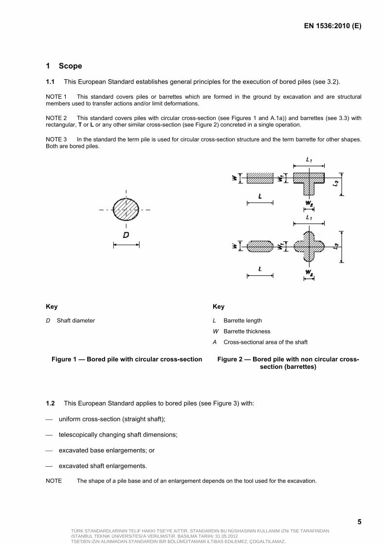
NOTE 2 This standard covers piles with circular cross-section (see Figures 1 and A.1a)) and barrettes (see 3.3) with rectangular, T or L or any other similar cross-section (see Figure 2) concreted in a single operation.
NOTE 3 In the standard the term pile is used for circular cross-section structure and the term barrette for other shapes. Both are bored piles.
Key Key
D Shaft diameter L Barrette length
W Barrette thickness
A Cross-sectional area of the shaft
Figure 1 — Bored pile with circular cross-section Figure 2 — Bored pile with non circular cross-section (barrettes)
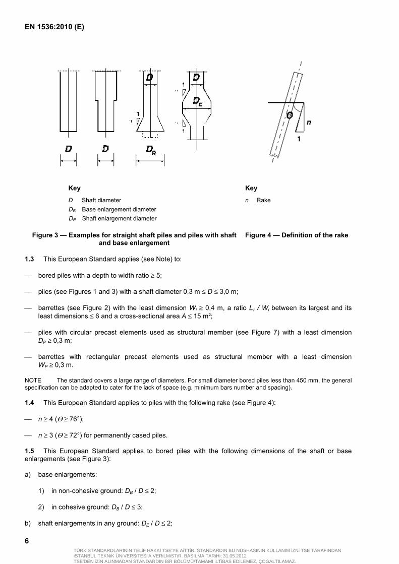
1.2 This European Standard applies to bored piles (see Figure 3) with:
uniform cross-section (straight shaft);
telescopically changing shaft dimensions;
excavated base enlargements; or
excavated shaft enlargements.
NOTE The shape of a pile base and of an enlargement depends on the tool used for the excavation.
TÜRK STANDARDLARININ TELiF HAKKI TSE'YE AiTTiR. STANDARDIN BU NÜSHASININ KULLANIM iZNi TSE TARAFINDANiSTANBUL TEKNiK ÜNiVERSiTESi'A VERiLMiSTiR. BASILMA TARiHi: 31.05.2012TSE'DEN iZiN ALINMADAN STANDARDIN BiR BÖLÜMÜ/TAMAMI iLTiBAS EDiLEMEZ, ÇOGALTILAMAZ.
EN 1536:2010 (E)
6
Key Key
D Shaft diameter n Rake DB Base enlargement diameter DE Shaft enlargement diameter
Figure 3 — Examples for straight shaft piles and piles with shaft and base enlargement
Figure 4 — Definition of the rake
1.3 This European Standard applies (see Note) to:
bored piles with a depth to width ratio ≥ 5;
piles (see Figures 1 and 3) with a shaft diameter 0,3 m ≤ D ≤ 3,0 m;
barrettes (see Figure 2) with the least dimension Wi ≥ 0,4 m, a ratio LBiB / Wi between its largest and its least dimensions ≤ 6 and a cross-sectional area A ≤ 15 m²;
piles with circular precast elements used as structural member (see Figure 7) with a least dimension DP ≥ 0,3 m;
barrettes with rectangular precast elements used as structural member with a least dimension WP ≥ 0,3 m.
NOTE The standard covers a large range of diameters. For small diameter bored piles less than 450 mm, the general specification can be adapted to cater for the lack of space (e.g. minimum bars number and spacing).
1.4 This European Standard applies to piles with the following rake (see Figure 4):
n ≥ 4 (Θ ≥ 76°);
n ≥ 3 (Θ ≥ 72°) for permanently cased piles.
1.5 This European Standard applies to bored piles with the following dimensions of the shaft or base enlargements (see Figure 3):
a) base enlargements:
1) in non-cohesive ground: DB / D ≤ 2;
2) in cohesive ground: DB / D ≤ 3;
b) shaft enlargements in any ground: DE / D ≤ 2;
TÜRK STANDARDLARININ TELiF HAKKI TSE'YE AiTTiR. STANDARDIN BU NÜSHASININ KULLANIM iZNi TSE TARAFINDANiSTANBUL TEKNiK ÜNiVERSiTESi'A VERiLMiSTiR. BASILMA TARiHi: 31.05.2012TSE'DEN iZiN ALINMADAN STANDARDIN BiR BÖLÜMÜ/TAMAMI iLTiBAS EDiLEMEZ, ÇOGALTILAMAZ.

EN 1536:2010 (E)
7
c) slope of the enlargement in non-cohesive ground m ≥ 3;
1) in non-cohesive ground: m ≥ 3;
2) in cohesive ground: m ≥ 1,5;
d) base enlargements area of barrettes: A ≤ 15 m²;
1.6 The provisions of this European Standard apply to:
single bored piles;
bored pile groups (see Figure 5);
walls formed by piles (see Figure 6).
Key D Shaft diameter ai Centre to centre spacing of the piles
Figure 5 — Examples of pile groups
TÜRK STANDARDLARININ TELiF HAKKI TSE'YE AiTTiR. STANDARDIN BU NÜSHASININ KULLANIM iZNi TSE TARAFINDANiSTANBUL TEKNiK ÜNiVERSiTESi'A VERiLMiSTiR. BASILMA TARiHi: 31.05.2012TSE'DEN iZiN ALINMADAN STANDARDIN BiR BÖLÜMÜ/TAMAMI iLTiBAS EDiLEMEZ, ÇOGALTILAMAZ.
EN 1536:2010 (E)
8
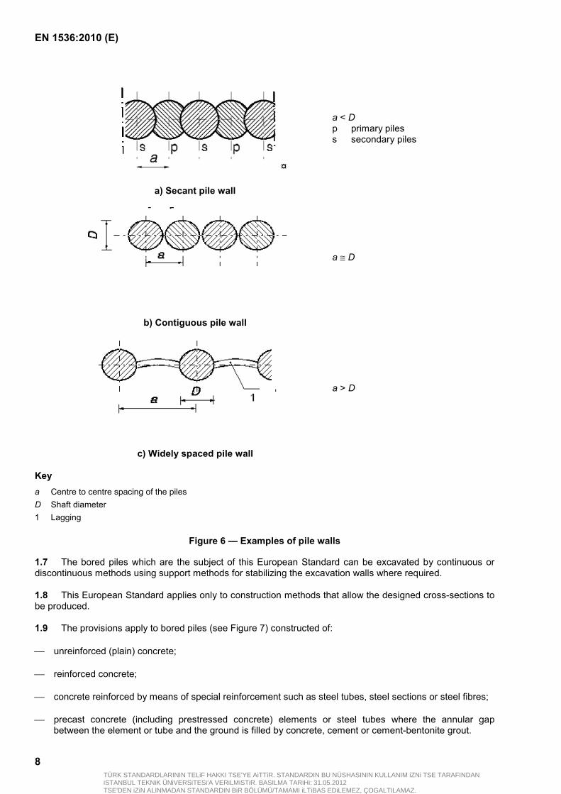
a < D p primary piles s secondary piles
a) Secant pile wall
a ≅ D
b) Contiguous pile wall
a > D
c) Widely spaced pile wall
Key a Centre to centre spacing of the piles D Shaft diameter 1 Lagging
Figure 6 — Examples of pile walls
1.7 The bored piles which are the subject of this European Standard can be excavated by continuous or discontinuous methods using support methods for stabilizing the excavation walls where required.
1.8 This European Standard applies only to construction methods that allow the designed cross-sections to be produced.
1.9 The provisions apply to bored piles (see Figure 7) constructed of:
unreinforced (plain) concrete;
reinforced concrete;
concrete reinforced by means of special reinforcement such as steel tubes, steel sections or steel fibres;
precast concrete (including prestressed concrete) elements or steel tubes where the annular gap between the element or tube and the ground is filled by concrete, cement or cement-bentonite grout.
TÜRK STANDARDLARININ TELiF HAKKI TSE'YE AiTTiR. STANDARDIN BU NÜSHASININ KULLANIM iZNi TSE TARAFINDANiSTANBUL TEKNiK ÜNiVERSiTESi'A VERiLMiSTiR. BASILMA TARiHi: 31.05.2012TSE'DEN iZiN ALINMADAN STANDARDIN BiR BÖLÜMÜ/TAMAMI iLTiBAS EDiLEMEZ, ÇOGALTILAMAZ.

EN 1536:2010 (E)
9
a) Use of plain concrete
b) Use of concrete with bar
reinforcement
c) Use of special reinforcement (steel section or tube)
d) Use of precast concrete element as main or supplementary structural member
e) Use of steel tube as main or supplementary
structural member
Key 1 Precast concrete element 2 Grout 3 Temporary casing (extracted) 4 Uncased excavation 5 Unreinforced or reinforced concrete or cement grout D Shaft diameter
Figure 7 — Examples of bored piles with circular cross-section
1.10 Micropiles, mixed-in-place columns, columns constructed by jet grouting, ground improvement for piling, mixed-in-place pile bases and diaphragm walls are not covered by this European Standard.
TÜRK STANDARDLARININ TELiF HAKKI TSE'YE AiTTiR. STANDARDIN BU NÜSHASININ KULLANIM iZNi TSE TARAFINDANiSTANBUL TEKNiK ÜNiVERSiTESi'A VERiLMiSTiR. BASILMA TARiHi: 31.05.2012TSE'DEN iZiN ALINMADAN STANDARDIN BiR BÖLÜMÜ/TAMAMI iLTiBAS EDiLEMEZ, ÇOGALTILAMAZ.

EN 1536:2010 (E)
10
2 Normative references
The following referenced documents are indispensable for the application of this document. For dated references, only the edition cited applies. For undated references, the latest edition of the referenced document (including any amendments) applies.
EN 197-1:2000, Cement ― Part 1: Composition, specifications and conformity criteria for common cements
EN 206-1:2000, Concrete — Part 1: Specification, performance, production and conformity
EN 791, Drill rigs ― Safety
EN 934-2, Admixtures for concrete, mortar and grout — Part 2: Concrete admixtures ― Definitions, requirements, conformity, marking and labelling
EN 996, Piling equipment ― Safety requirements
EN 1008, Mixing water for concrete ― Specification for sampling, testing and assessing the suitability of water, including water recovered from processes in the concrete industry, as mixing water for concrete
EN 1990, Eurocode ― Basis of structural design
EN 1991 (all parts), Eurocode 1: Actions on structures
EN 1992 (all parts), Eurocode 2: Design of concrete structures
EN 1993 (all parts), Eurocode 3: Design of steel structures
EN 1994 (all parts), Eurocode 4: Design of composite steel and concrete structures
EN 1997-1, Eurocode 7: Geotechnical design ― Part 1: General rules
EN 1997-2, Eurocode 7 ― Geotechnical design ― Part 2: Ground investigation and testing
EN 1998 (all parts), Eurocode 8: Design of structures for earthquake resistance
EN 10025-2, Hot rolled products of structural steels ― Part 2: Technical delivery conditions for non-alloy structural steels
EN 10080, Steel for the reinforcement of concrete ― Weldable reinforcing steel ― General
EN 10210 (all parts), Hot finished structural hollow sections of non-alloy and fine grain steels
EN 10219 (all parts), Cold formed welded structural hollow sections of non-alloy and fine grain steels
EN 10248 (all parts), Hot rolled sheet piling of non alloy steels
EN 10249 (all parts), Cold formed sheet piling of non alloy steels
EN 12620, Aggregates for concrete
EN 12794, Precast concrete products ― Foundation piles
EN 13670, Execution of concrete structures
ISO/DIS 22477-1, Geotechnical investigation and testing ― Testing of geotechnical structures ― Part 1: Pile load test by static axially loaded compression
TÜRK STANDARDLARININ TELiF HAKKI TSE'YE AiTTiR. STANDARDIN BU NÜSHASININ KULLANIM iZNi TSE TARAFINDANiSTANBUL TEKNiK ÜNiVERSiTESi'A VERiLMiSTiR. BASILMA TARiHi: 31.05.2012TSE'DEN iZiN ALINMADAN STANDARDIN BiR BÖLÜMÜ/TAMAMI iLTiBAS EDiLEMEZ, ÇOGALTILAMAZ.
EN 1536:2010 (E)
11
3 Terms and definitions
For the purposes of this document, the following terms and definitions apply.
NOTE 1 The following definitions are used for the construction of bored piles covered by this European Standard. Additional explanations of piling terms are listed in Annex A.
NOTE 2 In these definitions the term pile is used for circular cross-section structures and the term barrette for other shapes. Both are bored piles.
3.1 pile fr pieu de Pfahl slender structural member in the ground for the transfer of actions
3.2 bored pile fr pieu foré de Bohrpfahl pile or barrette formed with or without a pile casing by excavating or boring a hole in the ground and filling with plain or reinforced concrete
3.3 barrette fr barrette de Schlitzwandelement discrete length of diaphragm wall or a number of interconnecting lengths cast simultaneously (e.g. L-, T- or cruciform shapes) used to support vertical and/or lateral loads
3.4 continuous flight auger pile CFA-pile fr pieu à la tarière continue creuse (CFA) de Schneckenbohrpfahl pile formed by means of a hollow stemmed continuous flight auger through the stem of which concrete or grout is pumped as the auger is extracted
NOTE See Figure A.4.
3.5 prepacked pile fr pieu ballasté injecté de Prepacked-Pfahl pile where the completed excavation is filled with coarse aggregate which is subsequently injected with grout from the bottom up
3.6 end bearing pile fr pieu travaillant en pointe de Spitzendruckpfahl bored pile transmitting actions to the ground mainly by compression on its base
3.7 friction pile fr pieu flottant de Reibungspfahl bored pile transmitting actions to the ground mainly by friction and adhesion between the lateral surface of the pile and the adjacent ground
TÜRK STANDARDLARININ TELiF HAKKI TSE'YE AiTTiR. STANDARDIN BU NÜSHASININ KULLANIM iZNi TSE TARAFINDANiSTANBUL TEKNiK ÜNiVERSiTESi'A VERiLMiSTiR. BASILMA TARiHi: 31.05.2012TSE'DEN iZiN ALINMADAN STANDARDIN BiR BÖLÜMÜ/TAMAMI iLTiBAS EDiLEMEZ, ÇOGALTILAMAZ.
EN 1536:2010 (E)
12
3.8 pile base grouting fr injection sous la base de Pfahlfußverpressung pressure injection of grout below the base of an installed bored pile base in order to enhance performance under load
3.9 pile shaft grouting fr injection au niveau du fût de Pfahlmantelverpressung injection of grout carried out after bored pile concrete has set for the enhancement of skin friction accomplished by the use of grouting pipes which are installed down the shaft, normally placed with the bored pile reinforcement
3.10 working pile fr pieu de fondation de Bauwerkspfahl bored pile for the foundation of a structure or as part of a bored pile wall
3.11 raking pile fr pieu incliné de Schrägpfahl pile installed at an inclination related to the horizontal
NOTE See Figure 4.
3.12 shaft diameter fr diamètre du fût de Pfahlschaftdurchmesser diameter of the part of the pile between the pile head and the pile base:
for piles constructed with casings: equal to the external diameter of the casing;
for piles constructed without a casing: equal to the maximum diameter of the boring tool
3.13 enlarged base fr base élargie de Fußaufweitung base of a bored pile formed to have an area greater than that of its shaft
NOTE For bored piles, normally constructed by the use of special underreaming or belling-out tools (see Figure 3).
3.14 casting level fr niveau de bétonnage de Betonierhöhe upper level to which concrete is cast in a bored pile excavation
NOTE It is above the cut-off level by a margin depending on the execution procedure.
3.15 cut-off level (trimming) fr niveau d'arase (recépage) de planmäßige Pfahlkopfhöhe; Kapphöhe prescribed level to which a bored pile is trimmed before connecting it to the substructure
TÜRK STANDARDLARININ TELiF HAKKI TSE'YE AiTTiR. STANDARDIN BU NÜSHASININ KULLANIM iZNi TSE TARAFINDANiSTANBUL TEKNiK ÜNiVERSiTESi'A VERiLMiSTiR. BASILMA TARiHi: 31.05.2012TSE'DEN iZiN ALINMADAN STANDARDIN BiR BÖLÜMÜ/TAMAMI iLTiBAS EDiLEMEZ, ÇOGALTILAMAZ.
EN 1536:2010 (E)
13
3.16 empty bore fr forage vide de Leerbohrung length of excavation from the working level to the cut-off level
3.17 temporary casing fr tubage de Verrohrung steel tube used to maintain stability of a pile excavation (e.g. in unstable ground) which is withdrawn during or after concrete placement
3.18 permanent casing fr tubage permanent de bleibende Verrohrung; dauerhafte Verrohrung steel tube used to maintain stability of a pile excavation (e.g. in unstable ground) which is not withdrawn but remains as permanent continuous surround
NOTE It becomes part of the pile and may also act as a protective or load bearing unit.
3.19 lead-in tube fr virole de Führungsrohr short temporary casing put in place to secure the side of the excavation against collapse at the bore top close to working platform level
3.20 liner lining fr gaine, chemise de Hülse; Hülsenrohr tube, generally of thin steel plate, forming part of the pile shaft (e.g. used for the protection of pile shafts in soft grounds or to reduce negative skin friction)
3.21 support fluid fr fluide stabilisateur de Stützflüssigkeit fluid used during excavation to support bore hole walls and for flushing
NOTE It is usually a bentonite suspension or a polymer solution.
3.22 concreting pipe fr colonne de bétonnage de Betonierrohr, Schüttrohr metal pipe comprising several joined lengths, surmounted by a hopper or chute for concrete placement under dry conditions
3.23 tremie pipe fr tube plongeur de Kontraktorrohr concreting pipe, with watertight joints for submerged concrete placement
TÜRK STANDARDLARININ TELiF HAKKI TSE'YE AiTTiR. STANDARDIN BU NÜSHASININ KULLANIM iZNi TSE TARAFINDANiSTANBUL TEKNiK ÜNiVERSiTESi'A VERiLMiSTiR. BASILMA TARiHi: 31.05.2012TSE'DEN iZiN ALINMADAN STANDARDIN BiR BÖLÜMÜ/TAMAMI iLTiBAS EDiLEMEZ, ÇOGALTILAMAZ.
EN 1536:2010 (E)
14
3.24 integrity test fr essai d'intégrité de Integritätsprüfung test carried out on an installed bored pile for the verification of soundness of materials and of the pile geometry
3.25 sonic test fr essai d’auscultation sonique de Ultraschallversuch integrity test where a series of sonic waves is passed between a transmitter and a receiver through the concrete of a bored pile and where the characteristics of the received waves are measured and used to infer the state of continuity and section variations of the bored pile shaft
NOTE There are several types of sonic tests which measure the velocity of the wave either along the pile length or between a transmitter and a receiver placed at the same level in the shaft.
3.26 coring test fr essai d'auscultation sonique par transparence de Prüfung mittels Kernbohrung integrity test carried out from core drillings in a bored pile shaft
3.27 test pile fr pieu d'essai de Probepfahl zur Ermittlung Tragfähigkeit; Probebelastungspfahl bored pile to which loads are applied to determine the resistance deformation characteristics of the bored pile and the surrounding ground
NOTE Depending on the test performed, test pile can be working pile or expendable pile.
3.28 trial pile fr pieu de faisabilité de Probepfahl zur Prüfung Ausführbarkeit; Eignungspfahl bored pile installed to assess the practicability and suitability of the construction method for a particular application
NOTE A trial pile can also be used as a test pile.
3.29 static pile load test fr essai de chargement statique de pieu de statische Probebelastung loading test where a bored pile is subjected to chosen static axial and/or lateral actions at the bored pile head for the analysis of its capacity
3.30 maintained pile load test ML-test fr essai de chargement de pieu par palier de lastgesteuerte Probebelastung static loading test in which a test pile has loads applied in incremental stages, each of which is held constant for a certain period or until pile motion has virtually ceased or has reached a prescribed limit
TÜRK STANDARDLARININ TELiF HAKKI TSE'YE AiTTiR. STANDARDIN BU NÜSHASININ KULLANIM iZNi TSE TARAFINDANiSTANBUL TEKNiK ÜNiVERSiTESi'A VERiLMiSTiR. BASILMA TARiHi: 31.05.2012TSE'DEN iZiN ALINMADAN STANDARDIN BiR BÖLÜMÜ/TAMAMI iLTiBAS EDiLEMEZ, ÇOGALTILAMAZ.

EN 1536:2010 (E)
15
3.31 constant rate of penetration pile load test CRP-test fr essai de chargement de pieu à vitesse d'enfoncement constante de weggesteuerte Probebelastung static loading test in which a test bored pile is forced into the ground at a constant rate and the force is measured
3.32 dynamic pile load test fr essai de chargement dynamique de pieu de dynamischer Pfahlversuch loading test where a dynamic force is applied at the bored pile head for assessment of pile capacity
3.33 cutting ring fr trousse coupante de Bohrkrone; Schneidring bottom part of a casing, usually reinforced and with teeth to facilitate penetration into the ground
3.34 grout fr coulis de Mörtel; Injektionsgut, Verpressgut homogenous mixture of cement and water which may contain admixtures and additions
3.35 obstruction fr obstacle de Hindernis; Bohrhindernis natural (or man made) hard stratum, block or similar ground requiring special tools or methods for its excavation
3.36 skin (shaft) friction fr frottement latéral de Mantelreibung frictional and/or adhesive resistance on the bored pile surface
3.37 negative skin friction downdrag fr frottement négatif de negative Mantelreibung frictional and/or adhesive action by which surrounding soil or fill transfers downward load to a bored pile when the soil or fill settles relative to the bored pile shaft
3.38 socket fr ancrage de Felseinbindung; Pfahlfußeinbindung bottom part of a bored pile in hard ground (usually rock)
3.39 cover fr enrobage de Betonüberdeckung distance between the outside of the reinforcement cage and the nearest concrete surface
NOTE The nearest concrete surface considered is the nearest excavated face as formed by the excavation tool.
TÜRK STANDARDLARININ TELiF HAKKI TSE'YE AiTTiR. STANDARDIN BU NÜSHASININ KULLANIM iZNi TSE TARAFINDANiSTANBUL TEKNiK ÜNiVERSiTESi'A VERiLMiSTiR. BASILMA TARiHi: 31.05.2012TSE'DEN iZiN ALINMADAN STANDARDIN BiR BÖLÜMÜ/TAMAMI iLTiBAS EDiLEMEZ, ÇOGALTILAMAZ.

EN 1536:2010 (E)
16
3.40 execution specification fr specifications d'exécution de Ausführungsunterlagen set of documents covering all drawings, technical data and requirements necessary for the execution of a particular project
NOTE The execution specification is not one document but signifies the total sum of documents required for the execution of the work as provided by the designer to the constructor. It includes the project specification prepared to supplement and qualify the requirements of this European Standard, as well as referring the national provisions relevant in the place of use.
3.41 project specification fr spécifications de l'ouvrage de Projektspezifikationen project specific document describing the requirements applicable for the particular project
4 Information needed for the execution of the work
4.1 General
4.1.1 Prior to the execution of the work, all necessary information shall be provided.
4.1.2 This information should include:
any legal or statutory restrictions;
the location of main grid lines for setting out;
the conditions of structures, roads, services, etc. adjacent to the work, including any necessary surveys;
a suitable quality management system, including supervision, monitoring and testing.
4.1.3 The information regarding the site conditions shall cover, where relevant:
the geometry of the site (boundary conditions, topography, access, slopes, headroom restrictions, etc.);
the existing underground structures, services, known contaminations, and archeological constraints;
the environmental restrictions, including noise, vibration, pollution;
the future or ongoing activities such as dewatering, tunnelling, deep excavations.
4.2 Special features
4.2.1 The special features shall cover, where relevant:
execution specifications (see 3.40);
previous use of the site;
adjacent foundations (types, loads and geometry);
geotechnical information and data as specified in Clause 5;
presence of obstructions in the ground (old masonry, anchors, etc.);
TÜRK STANDARDLARININ TELiF HAKKI TSE'YE AiTTiR. STANDARDIN BU NÜSHASININ KULLANIM iZNi TSE TARAFINDANiSTANBUL TEKNiK ÜNiVERSiTESi'A VERiLMiSTiR. BASILMA TARiHi: 31.05.2012TSE'DEN iZiN ALINMADAN STANDARDIN BiR BÖLÜMÜ/TAMAMI iLTiBAS EDiLEMEZ, ÇOGALTILAMAZ.

EN 1536:2010 (E)
17
presence of headroom restrictions;
presence of archeological remains;
presence of natural and/or man made cavities (mines, etc.);
presence of polluted ground;
any specific requirements for the piling works, in particular those pertaining to tolerances, quality of materials;
where available, previous experience with bored piling or other foundations or underground works on or adjacent to the site;
proposed adjacent enabling or advance works such as underpinning, pre-treatment of soil, dewatering;
functional requirements for water tightness at joints of bored pile walls;
functional requirements for the material between the piles in the case of bored pile walls with a spacing a greater than the pile diameter D (see Figure 6).
4.2.2 Necessity, extent, procedure and content for any survey of the conditions of structures, roads, services, etc. adjacent to the works area shall be established.
4.2.3 The survey shall be carried out and be available prior to the commencement of the works and its conclusions shall be used to define the threshold values for any movement which may affect adjacent structures by the works area constructions.
4.2.4 Any additional or deviating requirements falling within the permissions given in this standard shall be established and agreed before the commencement of the works and the quality control system shall be suitably amended.
NOTE Such additional or deviating requirements can be:
— reduced or increased geometrical construction deviations;
— application of different or varying construction materials;
— precast concrete elements;
— special anchorage or doweling of bored piles to underlying rock;
— special reinforcement such as the use of steel tubes or sections or of steel fibres;
— grouting of bored pile shafts or bases;
— cutting-off of bored pile heads with heavy equipment;
— extensive manual excavation.
5 Geotechnical investigation
5.1 General
5.1.1 The geotechnical investigation shall fulfil the requirements of EN 1997 (all parts).
NOTE 1 The depth and the extent of the geotechnical investigation should be sufficient to identify all ground formations and layers affecting the construction, to determine the relevant properties of the ground and to recognize the ground
TÜRK STANDARDLARININ TELiF HAKKI TSE'YE AiTTiR. STANDARDIN BU NÜSHASININ KULLANIM iZNi TSE TARAFINDANiSTANBUL TEKNiK ÜNiVERSiTESi'A VERiLMiSTiR. BASILMA TARiHi: 31.05.2012TSE'DEN iZiN ALINMADAN STANDARDIN BiR BÖLÜMÜ/TAMAMI iLTiBAS EDiLEMEZ, ÇOGALTILAMAZ.
EN 1536:2010 (E)
18
conditions (e.g where end bearing is to be relied on, it should demonstrate that any competent founding stratum is not immediately underlain by a weaker stratum where there is a possibility of a punching failure or excessive movements).
NOTE 2 Relevant experience of the execution of comparable foundation works under similar conditions and/or in the vicinity of the site should be taken into account when determining the extent of site investigation (reference to relevant experience is permitted if appropriate means of verification are taken, e.g. by penetration, pressuremeter or other tests).
NOTE 3 Guidance is given in EN 1997-2 on the depth and the contents of investigations.
5.1.2 The geotechnical investigation report shall be available in time, to allow for reliable design and execution of the bored piles (e.g the choice of method of execution).
5.1.3 The sufficiency of the geotechnical investigation shall be checked for the design and execution of the bored piles.
5.1.4 If the geotechnical investigations are not sufficient, a supplementary investigation shall be conducted.
5.2 Specific requirements
5.2.1 Particular attention shall be paid to the following aspects, which are relevant to the execution of bored piles:
the ground level at any point of investigation or testing relative to the recognised national datum or to a fixed reference chart datum;
piezometric levels of all water-tables and permeability of the soils;
presence of coarse, highly permeable soils or cavities (natural or artificial), which can cause sudden losses of support fluid and instability of the bore during the excavation or can cause a sudden drop of concrete during the placement, and thus can require special measures;
presence, strength and deformation characteristics of soft soils, such as very soft clay or peat, which can cause difficulties during excavation or concreting (deformation or instability);
presence of boulders or obstructions which can cause difficulties during excavation and, an assessment of their size and frequency, when applicable;
presence, position, strength of hard rock or other hard materials which can cause difficulties during excavation and may require the use of special tools;
presence, extent and thickness of any strata that can be sensitive to water infiltration or to stress caused by piling tools (e.g. impact, percussion or vibration);
underground strata where high ground-water velocities exist;
detrimental chemistry of groundwater, soil and rock, and water temperatures if required;
detrimental chemistry of waste materials;
presence of pretreated soil, which can have an adverse effect during excavation;
mining beneath the site;
site stability problems (slope stability for instance).
5.2.2 The piezometric levels of the various water-tables existing on the site shall be monitored separately and over a sufficient period of time to estimate the highest piezometric levels which can occur during construction of the piles.
TÜRK STANDARDLARININ TELiF HAKKI TSE'YE AiTTiR. STANDARDIN BU NÜSHASININ KULLANIM iZNi TSE TARAFINDANiSTANBUL TEKNiK ÜNiVERSiTESi'A VERiLMiSTiR. BASILMA TARiHi: 31.05.2012TSE'DEN iZiN ALINMADAN STANDARDIN BiR BÖLÜMÜ/TAMAMI iLTiBAS EDiLEMEZ, ÇOGALTILAMAZ.
EN 1536:2010 (E)
19
5.2.3 Particular attention shall be paid to artesian conditions.
5.2.4 The strength of the soils and rocks shall be determined by laboratory tests and/or in situ tests over the full depth of the bored piles and to a certain depth below their base.
NOTE The investigation depth depends on the nature of the ground and the function of the piles (foundation or retaining structure).
5.2.5 When bored piles are required to reach or penetrate into rock, the level of the rock surface shall be determined.
NOTE The area to investigate depends on the function of the piles (foundation or retaining structure).
5.2.6 When bored pile walls are required to reach or penetrate into rock, the properties of the rock, including the degree of weathering and the extent and direction of fissuring shall be assessed.
6 Materials and products
6.1 Constituents
6.1.1 General
6.1.1.1 The constituents shall meet the requirements set in the respective European Standards, the provisions valid in the place of use and the provisions given in the project specification.
6.1.1.2 The sources of supply of constituents shall be documented and shall not be changed without prior notification.
6.1.2 Bentonite
6.1.2.1 A distinction should be made between calcium bentonite, natural sodium bentonite and activated bentonite, which is a sodium bentonite produced from natural calcium bentonite by ion exchange.
NOTE 1 Bentonite is a clay containing mainly the mineral montmorillonite.
NOTE 2 Bentonite is used in support fluids, either as a pure bentonite suspension or as an addition to polymers solutions. It is also used as a constituent part of hardening slurries and of plastic concrete.
6.1.2.2 Bentonite used in bentonite suspensions shall not contain harmful constituents in such quantities as can be detrimental to reinforcement or concrete.
6.1.2.3 The chemical and mineralogical composition of the bentonite shall be supplied.
6.1.3 Polymers
Polymers can be used as sole constituent in supporting fluids or as additives to enhance rheological effectiveness.
NOTE 1 Polymers are materials formed of molecules from chained monomeric units.
NOTE 2 There are different types of polymers ranging from natural gums to specially tailored blends of synthetic products.
6.1.4 Cement
6.1.4.1 Cement for bored piles shall be of the following types as defined in EN 197-1:2000:
TÜRK STANDARDLARININ TELiF HAKKI TSE'YE AiTTiR. STANDARDIN BU NÜSHASININ KULLANIM iZNi TSE TARAFINDANiSTANBUL TEKNiK ÜNiVERSiTESi'A VERiLMiSTiR. BASILMA TARiHi: 31.05.2012TSE'DEN iZiN ALINMADAN STANDARDIN BiR BÖLÜMÜ/TAMAMI iLTiBAS EDiLEMEZ, ÇOGALTILAMAZ.

EN 1536:2010 (E)
20
Portland cement CEM I;
Portland-slag cement CEM II/A-S and II/B-S;
Portland-silica fume cement CEM II/A-D;
Portland-pozzolana cement CEM II/A-P and II/B-P;
Portland-fly ash cement CEM II/A-V and II/B-V;
Portland-burnt shale cement CEM II/A-T and II/B-T;
Portland-limestone cement CEM II/A-LL;
Portland-composite cement CEM II/A-M (S-V) and CEM II/B-M (S-V);
Portland-composite cements CEM IIA-M (S-LL, V-LL) and CEM IIB-M (S-LL, V-LL);
Blast furnace cement CEM III/A, III/B and III/C.
6.1.4.2 Other cement types may be used when specified and of proven performance in the specific conditions according to EN 206-1.
6.1.4.3 The use of cement with high sulphate resistance (i.e. free of CB3BA -Tricalciumaluminate) shall comply with the provisions valid in the place of use.
NOTE 1 They are used for instance in cool, wet environments with presence of sulphate (e.g. seawater structures).
NOTE 2 Where a European Standard does not exist and where there are no local regulation, comparable experience and/or specific studies are necessary.
6.1.4.4 Calcium aluminate cement shall not be used.
6.1.4.5 The use of CEM II or CEM III cement or the partial replacement of CEM I cement by type II additions is recommended because they have been shown to have beneficial effects on concrete, such as:
improved workability;
reduced heat generation during setting;
improved durability; and
reduced bleeding rate.
NOTE 1 The use of CEM III cement type or the replacement of CEM I cement type by ground granulated blastfurnace slag can result in reduced permeability.
NOTE 2 Bleeding is less likely to be significant with cements with fineness of grind (Blaine) of 3 800 cmP
2P/g or more.
6.1.4.6 Type II addition including fly ash, silica fume (as defined in EN 206-1:2000) and ground granulated blast furnace slag may be used as cement replacement.
6.1.4.7 The equivalent cementitious values of the addition shall be established using the k-value concept in EN 206-1:2000 or alternatively ground granulated blast furnace slag and other additions may be used according to the Equivalent Performance of Combinations Concept.
6.1.5 Aggregates
Aggregates shall comply with EN 12620 and EN 206-1.
TÜRK STANDARDLARININ TELiF HAKKI TSE'YE AiTTiR. STANDARDIN BU NÜSHASININ KULLANIM iZNi TSE TARAFINDANiSTANBUL TEKNiK ÜNiVERSiTESi'A VERiLMiSTiR. BASILMA TARiHi: 31.05.2012TSE'DEN iZiN ALINMADAN STANDARDIN BiR BÖLÜMÜ/TAMAMI iLTiBAS EDiLEMEZ, ÇOGALTILAMAZ.
EN 1536:2010 (E)
21
6.1.6 Water
Mixing water shall comply with EN 1008 and EN 206-1.
6.1.7 Additions
The use of additions shall comply with EN 206-1.
6.1.8 Admixtures
6.1.8.1 Admixtures shall comply with EN 934-2.
6.1.8.2 Where respective specific European Standards are not available, the use of admixtures shall be in accordance with the national standards and/or regulations in the place of use of the concrete.
6.1.8.3 Admixtures shall be used in accordance with the specification document and the manufacturer's instructions.
6.2 Support fluids
6.2.1 Bentonite suspensions
6.2.1.1 A bentonite suspension shall be prepared with either natural or activated sodium bentonite.
6.2.1.2 In certain cases, e.g. when the density of the suspension has to be increased, suitable inert materials may be added.
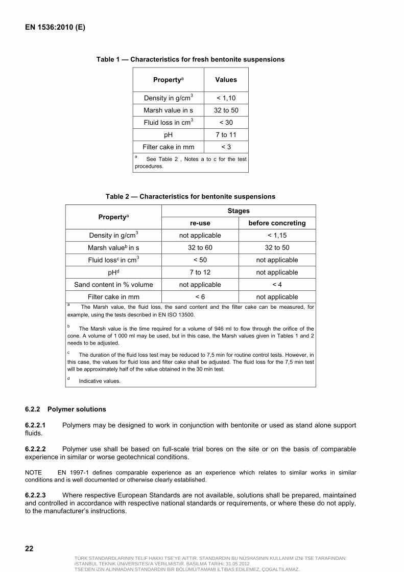
6.2.1.3 Other than in special circumstances (see Notes), the fresh bentonite suspension shall meet the conditions shown in Table 1 and the "re-use" or "before concreting" bentonite suspension shall meet the conditions shown in Table 2.
NOTE 1 Special circumstances are for example:
— soils or rock with high permeability or cavities where loss of bentonite can occur;
— high piezometric ground water levels (confined or artesian conditions);
— loose sand or soft soils (typically with qcB < 300 kPa or Cu < 15 kPa);
— salt water conditions.
NOTE 2 A bentonite suspension with sufficient shear strength can be required, e.g in order to reduce penetration into the ground.
6.2.1.4 At the stage before concreting, a value of density up to 1,20 g/cm³ is permitted for special cases such as in salty water or very soft soil.
6.2.1.5 At the stage before concreting, a value up to 6 % by mass for sand content is permitted for special cases such as friction or unreinforced bored piles.
6.2.1.6 Where bentonite suspension is also used as a means of transport for the excavated material, higher densities are permitted during the excavation process for the re-use stage.
TÜRK STANDARDLARININ TELiF HAKKI TSE'YE AiTTiR. STANDARDIN BU NÜSHASININ KULLANIM iZNi TSE TARAFINDANiSTANBUL TEKNiK ÜNiVERSiTESi'A VERiLMiSTiR. BASILMA TARiHi: 31.05.2012TSE'DEN iZiN ALINMADAN STANDARDIN BiR BÖLÜMÜ/TAMAMI iLTiBAS EDiLEMEZ, ÇOGALTILAMAZ.
EN 1536:2010 (E)
22
Table 1 — Characteristics for fresh bentonite suspensions
Propertya Values
Density in g/cm3 < 1,10
Marsh value in s 32 to 50
Fluid loss in cm3 < 30
pH 7 to 11
Filter cake in mm < 3 a See Table 2 , Notes a to c for the test procedures.
Table 2 — Characteristics for bentonite suspensions
Propertya
Stages
re-use before concreting
Density in g/cm3 not applicable < 1,15
Marsh valueb in s 32 to 60 32 to 50
Fluid lossc in cm3 < 50 not applicable
pHd 7 to 12 not applicable
Sand content in % volume not applicable < 4
Filter cake in mm < 6 not applicable a The Marsh value, the fluid loss, the sand content and the filter cake can be measured, for
example, using the tests described in EN ISO 13500.
b The Marsh value is the time required for a volume of 946 ml to flow through the orifice of the
cone. A volume of 1 000 ml may be used, but in this case, the Marsh values given in Tables 1 and 2 needs to be adjusted. c The duration of the fluid loss test may be reduced to 7,5 min for routine control tests. However, in
this case, the values for fluid loss and filter cake shall be adjusted. The fluid loss for the 7,5 min test will be approximately half of the value obtained in the 30 min test. d Indicative values.
6.2.2 Polymer solutions
6.2.2.1 Polymers may be designed to work in conjunction with bentonite or used as stand alone support fluids.
6.2.2.2 Polymer use shall be based on full-scale trial bores on the site or on the basis of comparable experience in similar or worse geotechnical conditions.
NOTE EN 1997-1 defines comparable experience as an experience which relates to similar works in similar conditions and is well documented or otherwise clearly established.
6.2.2.3 Where respective European Standards are not available, solutions shall be prepared, maintained and controlled in accordance with respective national standards or requirements, or where these do not apply, to the manufacturer’s instructions.
TÜRK STANDARDLARININ TELiF HAKKI TSE'YE AiTTiR. STANDARDIN BU NÜSHASININ KULLANIM iZNi TSE TARAFINDANiSTANBUL TEKNiK ÜNiVERSiTESi'A VERiLMiSTiR. BASILMA TARiHi: 31.05.2012TSE'DEN iZiN ALINMADAN STANDARDIN BiR BÖLÜMÜ/TAMAMI iLTiBAS EDiLEMEZ, ÇOGALTILAMAZ.
EN 1536:2010 (E)
23
6.3 Concrete
6.3.1 General
6.3.1.1 Unless otherwise stated, concrete used in cast in situ concrete bored pile shall comply with EN 206-1.
6.3.1.2 Cast in situ concrete shall be composed to minimize segregation during placing, to flow easily around the reinforcement, and when set, to provide a dense and watertight material.
6.3.1.3 The concrete shall comply with the requirements related to strength and durability in the hardened state as well as with the requirements related to consistency in the fresh state.
NOTE 1 Compressive strength classes for hardened concrete are given in EN 206-1:2000. The range usually used for bored piles is between C20/25 and C45/55.
NOTE 2 For primary piles of pile walls a lower compressive strength class of concrete or mortar is usually used (see Figure 6).
NOTE 3 Higher compressive strength concrete may be used.
6.3.2 Aggregates
6.3.2.1 In order to minimize segregation, aggregates shall not be gap graded and round aggregates are preferred.
6.3.2.2 The maximum size of the aggregate shall not exceed 32 mm or ¼ of the clear space between the longitudinal bars, whichever is the smaller.
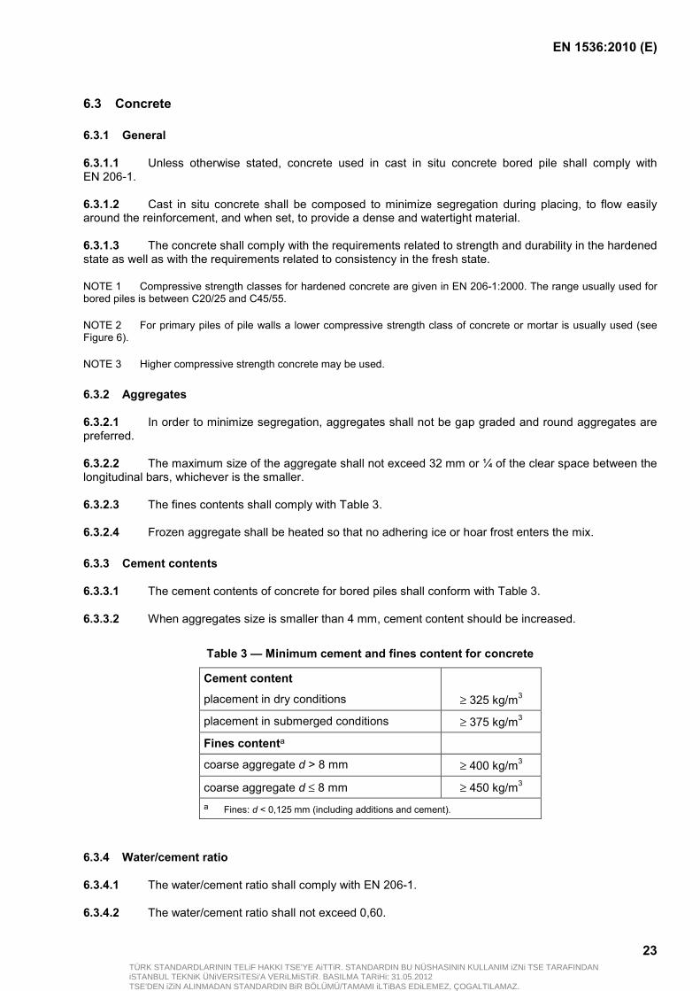
6.3.2.3 The fines contents shall comply with Table 3.
6.3.2.4 Frozen aggregate shall be heated so that no adhering ice or hoar frost enters the mix.
6.3.3 Cement contents
6.3.3.1 The cement contents of concrete for bored piles shall conform with Table 3.
6.3.3.2 When aggregates size is smaller than 4 mm, cement content should be increased.
Table 3 — Minimum cement and fines content for concrete
Cement content
placement in dry conditions
≥ 325 kg/m3
placement in submerged conditions ≥ 375 kg/m3
Fines contenta
coarse aggregate d > 8 mm ≥ 400 kg/m3
coarse aggregate d ≤ 8 mm ≥ 450 kg/m3 a Fines: d < 0,125 mm (including additions and cement).
6.3.4 Water/cement ratio
6.3.4.1 The water/cement ratio shall comply with EN 206-1.
6.3.4.2 The water/cement ratio shall not exceed 0,60.
TÜRK STANDARDLARININ TELiF HAKKI TSE'YE AiTTiR. STANDARDIN BU NÜSHASININ KULLANIM iZNi TSE TARAFINDANiSTANBUL TEKNiK ÜNiVERSiTESi'A VERiLMiSTiR. BASILMA TARiHi: 31.05.2012TSE'DEN iZiN ALINMADAN STANDARDIN BiR BÖLÜMÜ/TAMAMI iLTiBAS EDiLEMEZ, ÇOGALTILAMAZ.
EN 1536:2010 (E)
24
6.3.4.3 Water may be chilled or may be replaced by up to 50 % of its mass by ice-chips for cooling of fresh concrete at high ambient temperatures.
6.3.5 Admixtures
6.3.5.1 Admixtures used shall comply with EN 206-1.
NOTE 1 The admixtures commonly used for concreting are:
— water reducing/plasticizing;
— high range water reducing/super-plasticizing; and
— set retarding.
NOTE 2 Admixtures are used:
— to give a mix of high plasticity;
— to improve concrete flow;
— to minimise bleeding and avoid honeycombing or segregation that might otherwise result from a high water content;
— to prolong the workability as required for the duration of the placement and to cater for any interruptions in the placement process.
NOTE 3 Inappropriate application of admixtures can result into damages.
6.3.5.2 A concrete with consistence class of F5 or higher (respectively S4 or higher) may be produced without the use of high range water reducing admixtures (superplasticisers).
6.3.5.3 Where bored piles are constructed in a cold climate and the ground surrounding the upper part of the bored pile is to be excavated after concreting, air entraining admixtures may be used in the concrete for the part of the bored pile to be exposed to frost action.
6.3.6 Fresh concrete
6.3.6.1 Concrete for bored piles shall:
have a high resistance against segregation;
be of high plasticity and good cohesiveness;
flow well;
be adequately self-compacting; and
be sufficiently workable for the duration of the placement procedure, including the removal of any temporary casings.
6.3.6.2 The slump test or the flow table test can be used to evaluate the consistence of the fresh concrete and the target value concept defined in EN 206-1:2000 applies.
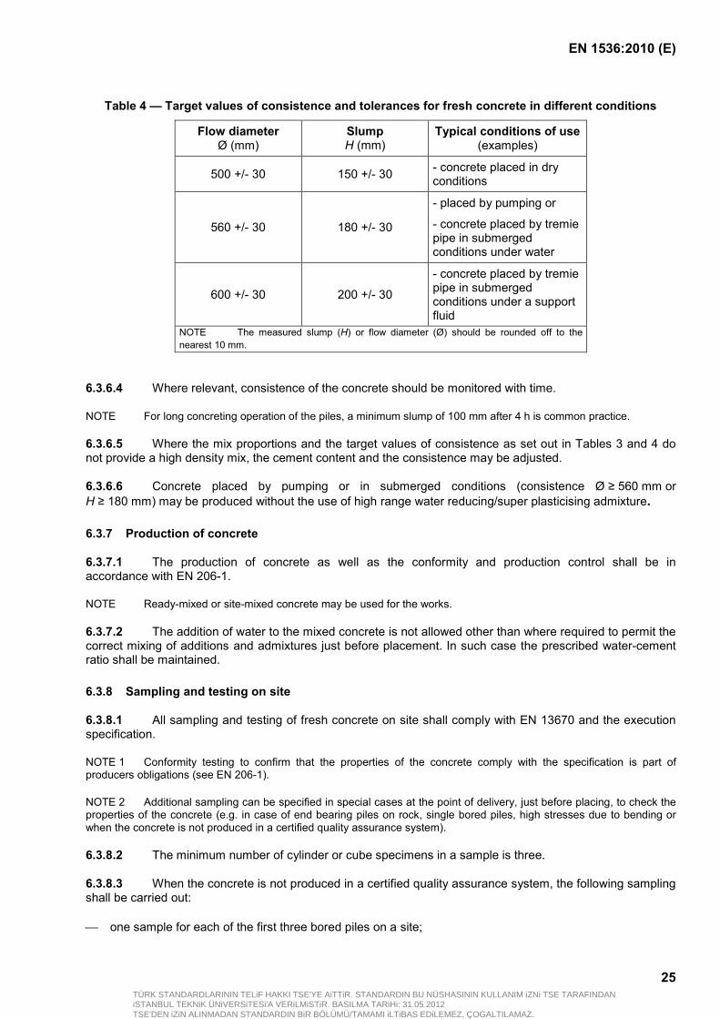
6.3.6.3 The target values of consistence and tolerances for the fresh concrete before placing in different conditions of use shall comply with Table 4.
TÜRK STANDARDLARININ TELiF HAKKI TSE'YE AiTTiR. STANDARDIN BU NÜSHASININ KULLANIM iZNi TSE TARAFINDANiSTANBUL TEKNiK ÜNiVERSiTESi'A VERiLMiSTiR. BASILMA TARiHi: 31.05.2012TSE'DEN iZiN ALINMADAN STANDARDIN BiR BÖLÜMÜ/TAMAMI iLTiBAS EDiLEMEZ, ÇOGALTILAMAZ.
EN 1536:2010 (E)
25
Table 4 — Target values of consistence and tolerances for fresh concrete in different conditions
Flow diameter Ø (mm)
Slump H (mm)
Typical conditions of use (examples)
500 +/- 30 150 +/- 30 - concrete placed in dry conditions
560 +/- 30 180 +/- 30
- placed by pumping or
- concrete placed by tremie pipe in submerged conditions under water
600 +/- 30 200 +/- 30
- concrete placed by tremie pipe in submerged conditions under a support fluid
NOTE The measured slump (H) or flow diameter (Ø) should be rounded off to the nearest 10 mm.
6.3.6.4 Where relevant, consistence of the concrete should be monitored with time.
NOTE For long concreting operation of the piles, a minimum slump of 100 mm after 4 h is common practice.
6.3.6.5 Where the mix proportions and the target values of consistence as set out in Tables 3 and 4 do not provide a high density mix, the cement content and the consistence may be adjusted.
6.3.6.6 Concrete placed by pumping or in submerged conditions (consistence Ø ≥ 560 mm or H ≥ 180 mm) may be produced without the use of high range water reducing/super plasticising admixture.
6.3.7 Production of concrete
6.3.7.1 The production of concrete as well as the conformity and production control shall be in accordance with EN 206-1.
NOTE Ready-mixed or site-mixed concrete may be used for the works.
6.3.7.2 The addition of water to the mixed concrete is not allowed other than where required to permit the correct mixing of additions and admixtures just before placement. In such case the prescribed water-cement ratio shall be maintained.
6.3.8 Sampling and testing on site
6.3.8.1 All sampling and testing of fresh concrete on site shall comply with EN 13670 and the execution specification.
NOTE 1 Conformity testing to confirm that the properties of the concrete comply with the specification is part of producers obligations (see EN 206-1).
NOTE 2 Additional sampling can be specified in special cases at the point of delivery, just before placing, to check the properties of the concrete (e.g. in case of end bearing piles on rock, single bored piles, high stresses due to bending or when the concrete is not produced in a certified quality assurance system).
6.3.8.2 The minimum number of cylinder or cube specimens in a sample is three.
6.3.8.3 When the concrete is not produced in a certified quality assurance system, the following sampling shall be carried out:
one sample for each of the first three bored piles on a site;
TÜRK STANDARDLARININ TELiF HAKKI TSE'YE AiTTiR. STANDARDIN BU NÜSHASININ KULLANIM iZNi TSE TARAFINDANiSTANBUL TEKNiK ÜNiVERSiTESi'A VERiLMiSTiR. BASILMA TARiHi: 31.05.2012TSE'DEN iZiN ALINMADAN STANDARDIN BiR BÖLÜMÜ/TAMAMI iLTiBAS EDiLEMEZ, ÇOGALTILAMAZ.
EN 1536:2010 (E)
26
one sample for every subsequent five bored piles (15 bored piles if the individual concrete volume is 4 m³ or less);
two additional samples after interruptions of the works longer than seven days;
at least one sample for every 75 m³ of concrete cast on the same day;
at least one sample for every bored pile cast where concrete stresses require concrete classes C35/45 and above.
6.3.8.4 When the concrete is not produced in a certified quality assurance system, the characteristic compressive strength shall be determined for each sample at least on one specimen tested at seven days and one specimen tested at 28 days (see Note).
NOTE For each sample, at least one specimen is kept until conformity of concrete compressive strength is assessed on specimens tested at 28 days.
6.3.8.5 Where the concrete is produced in a continuous and certified quality assurance system, deviating requirements from those of non-certified quality assurance system for concrete sampling on site may be specified.
6.3.8.6 The frequency of testing of consistence, concrete temperature and workability time shall comply with the execution specification.
NOTE Guidance is given in Annex B in Tables B.1 to B.4.
6.3.8.7 A full record of all tests carried out on the concrete shall be kept and results shall be noted in the concrete placement record.
6.4 Grout
6.4.1 Where relevant European Standards are not available, cement-bentonite grouts and any other grouts shall be prepared, maintained and controlled in accordance with the respective national standards and/or regulations in the place of use.
NOTE There are three European Standards for grout for prestressing systems: EN 445, EN 446 and EN 447. The requirements of these stantards are not applicable to this standard.
6.4.2 Grout composition and the grouting technique and procedure shall be planned, carried out and documented in a manner appropriate to the application (e.g. external grouting around precast elements, base or shaft grouting) and the ground condition.
6.4.3 When selecting the type of cement for grout placed in contact with the ground, account shall be taken of the known or possible presence of aggressive substances.
6.4.4 Water/cement ratios should be appropriate to actual ground conditions.
NOTE The water/cement ratios may typically range from 0,40 to 0,55 or more, if judged necessary.
6.4.5 To create a pumpable grout mix with a low bleed rate, admixtures may be used.
6.5 Reinforcement
6.5.1 Reinforcement material used in bored piles shall comply with the relevant European Standards, this standard and the execution specification.
6.5.2 The reinforcement steel cages used in bored piles shall comply with EN 10080.
TÜRK STANDARDLARININ TELiF HAKKI TSE'YE AiTTiR. STANDARDIN BU NÜSHASININ KULLANIM iZNi TSE TARAFINDANiSTANBUL TEKNiK ÜNiVERSiTESi'A VERiLMiSTiR. BASILMA TARiHi: 31.05.2012TSE'DEN iZiN ALINMADAN STANDARDIN BiR BÖLÜMÜ/TAMAMI iLTiBAS EDiLEMEZ, ÇOGALTILAMAZ.
EN 1536:2010 (E)
27
6.5.3 The steel elements used in bored piles shall comply with EN 10025-2, EN 10210 (all parts), EN 10219 (all parts), EN 10248 (all parts), EN 10249 (all parts) and EN 13670 where relevant.
NOTE Different types of steel element may be used such as cold formed or hot rolled sheet pile products or structural hollow products, etc.
6.5.4 Materials other than steel to be used as reinforcement such as glass fibre shall have an established suitability and be in accordance with the requirements given in the execution specification.
6.5.5 Unless special precautions are taken, metallic elements used in bored piles, such as access pipes for testing purpose, shall not be made of galvanized steel or other metals which can produce electrostatic effects causing electrochemical corrosion of the reinforcement.
NOTE Electrostatic effects can also adversely affect support fluids, for example build up of a bentonite layer using bentonite suspensions or spider web formation in polymer suspensions which can inhibit successful concreting.
6.6 Additional inserted products
6.6.1 Inserts (e.g pipes, instruments) shall comply with the relevant European Standards.
6.6.2 Where no relevant European Standards exist, the inserts shall comply with national standards and/or with the specifications of the manufacturer.
7 Considerations related to design
7.1 General
7.1.1 The basic European Standards for the design of bored piles are EN 1990, EN 1991 (all parts), EN 1992 (all parts), EN 1993 (all parts), EN 1994 (all parts), EN 1997 (all parts) and EN 1998 (all parts). Clause 7 relates to matters, resulting from the execution of bored piles which can affect the design.
7.1.2 Bored piles design shall take into account the construction tolerances given in 8.1 and the execution conditions as set in Clause 8.
NOTE For example the determination of eccentricity of the forces applied on pile head to be considered is the sum of horizontal and vertical tolerances in between the working platform level and the cut-off level.
7.1.3 Adequate protection against aggressiveness of subsoil and/or groundwater shall be provided, e.g. by mix design or permanent lining.
NOTE 1 Contaminated ground and water can be additional risks (e.g. retarding influence or changes in the pore-structure of the concrete by heavy metals).
NOTE 2 In particularly severe water or ground conditions sufficient protection might not be provided through mix design only.
NOTE 3 Reliable protection for the fresh concrete against groundwater flow that might have a washing-out effect can be achieved by means of a permanent casing or lining.
7.1.4 The effect of the installation of a permanent lining on the recovery of a temporary casing and/or on the shaft friction should be considered in the design.
NOTE When linings are employed the skin friction can be affected and its value can be uncertain.
7.1.5 A bored pile may be designed as an unreinforced concrete element if:
pile head reinforcement is provided in accordance with 7.1.6 and 7.1.8; and
TÜRK STANDARDLARININ TELiF HAKKI TSE'YE AiTTiR. STANDARDIN BU NÜSHASININ KULLANIM iZNi TSE TARAFINDANiSTANBUL TEKNiK ÜNiVERSiTESi'A VERiLMiSTiR. BASILMA TARiHi: 31.05.2012TSE'DEN iZiN ALINMADAN STANDARDIN BiR BÖLÜMÜ/TAMAMI iLTiBAS EDiLEMEZ, ÇOGALTILAMAZ.
EN 1536:2010 (E)
28
the design actions and/or actions caused by the construction and/or actions resulting from the ground produce only compressive stresses in the bored pile.
7.1.6 Bored pile heads for unreinforced bored piles shall be reinforced to cater for accidental loads (e.g. resulting from all construction works on the site).
NOTE Base enlargements of bored piles are usually constructed without reinforcement beyond that required (if any) in the shaft.
7.1.7 A bored pile should be reinforced over any length of soft or loose soil.
NOTE Examples of characteristics of soft and loose soil (e.g. cohesion of soft clay, density index and cone resistance of loose sand) are given in EN 1997-2.
7.1.8 If there is no design requirement for reinforcement, starter bars or another system should be placed in the bored pile head to locate the centre of the pile.
NOTE 1 Bored piles with head enlargements are usually constructed with stater bars in the bored pile head.
NOTE 2 When the casting level is too deep and/or after trimming, starter bars are not appropriate for the location of the pile centre.
7.1.9 Where permitted by the execution specifications, reinforcement cages may be installed after concrete placement.
NOTE Special robust and rigid cages can be necessary.
7.2 Piles forming a wall
7.2.1 The design of wall made of piles should take into acccount only the reinforced element.
NOTE Normally in the construction of secant pile walls, primary piles are unreinforced over their whole length and secondary piles are reinforced and are constructed after the initially installed unreinforced piles on either side are in place.
7.2.2 The geometrical construction tolerances for piles forming a wall can be more demanding than the values indicated in 8.2, particularly when soil or water tightness is required.
7.2.3 The rake, spacing, geometrical construction tolerances, overlap and requirements for water tightness of joints in walls shall be specified in the execution specification.
7.3 Excavation
7.3.1 When bored piles are to be socketed into a bearing stratum or into rock, the design shall specify the shape, the minimum depth of penetration and the quality of the material in which the socket is to be formed.
7.3.2 Where ground conditions differ from those stipulated in the execution specification, the designer shall be notified and appropriate action shall be taken.
7.3.3 Compression bored piles shall not be founded on obstructions unless:
sufficient bearing resistance is proven;
full face seating; and
similar deformation behaviour with respect to adjacent bored piles can be achieved.
7.3.4 If bored piles encounter an impenetrable obstruction prior to reaching their designed founding depth, the design shall be reviewed in the light of any available knowledge about the obstruction.
NOTE Additional or supplementary bored piles of equivalent performance can be necessary in this case.
TÜRK STANDARDLARININ TELiF HAKKI TSE'YE AiTTiR. STANDARDIN BU NÜSHASININ KULLANIM iZNi TSE TARAFINDANiSTANBUL TEKNiK ÜNiVERSiTESi'A VERiLMiSTiR. BASILMA TARiHi: 31.05.2012TSE'DEN iZiN ALINMADAN STANDARDIN BiR BÖLÜMÜ/TAMAMI iLTiBAS EDiLEMEZ, ÇOGALTILAMAZ.
EN 1536:2010 (E)
29
7.3.5 Enlargements of a bored pile base or shaft shall be designed only when the intended shape can be constructed in a controllable way and checked by suitable methods.
7.3.6 Base enlargements shall not be specified in unstable soils such as:
loose sands;
uniform sands below the ground-water table;
soft or sensitive clays.
7.3.7 Shaft enlargements shall be specified only for vertical piles in stable ground.
7.4 Precast concrete elements
7.4.1 The design, execution and supervision of precast concrete elements shall be in accordance with EN 1992 (all parts) and EN 12794.
7.4.2 The design shall consider the cases of handling, transportation and installation; any restrictions shall be marked on the element.
7.4.3 The concrete cover shall be in accordance with the requirements for the respective environmental conditions.
7.4.4 The bond stress between the external grout and the precast concrete element shall be demonstrated.
7.5 Reinforcement
7.5.1 General
7.5.1.1 The design of starter bars or dowel bars for connection to a superstructure shall be in accordance with EN 1992 (all parts).
7.5.1.2 An allowance for corrosion shall be made in the design where a steel reinforcement pipe or a permanent casing is used as a structural member, unless protection is already naturally present or the entire surface is protected by a sufficient concrete or grout cover or other protective measures.
7.5.1.3 All necessary measures to provide cage rigidity should be shown on the working drawings.
7.5.1.4 The lap of bars should be located away from the maximum bending area.
7.5.2 Longitudinal reinforcement
7.5.2.1 Where a bentonite, clay or polymer suspension is used as a support fluid, only ribbed bars shall be used for main reinforcement.
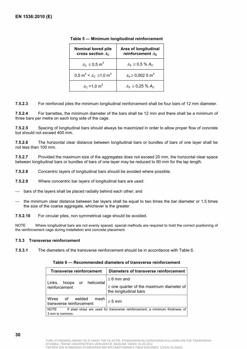
7.5.2.2 Unless otherwise specified by design the minimum amount of longitudinal reinforcement shall be as indicated in Table 5 where reinforcement is required.
TÜRK STANDARDLARININ TELiF HAKKI TSE'YE AiTTiR. STANDARDIN BU NÜSHASININ KULLANIM iZNi TSE TARAFINDANiSTANBUL TEKNiK ÜNiVERSiTESi'A VERiLMiSTiR. BASILMA TARiHi: 31.05.2012TSE'DEN iZiN ALINMADAN STANDARDIN BiR BÖLÜMÜ/TAMAMI iLTiBAS EDiLEMEZ, ÇOGALTILAMAZ.
EN 1536:2010 (E)
30
Table 5 — Minimum longitudinal reinforcement
Nominal bored pile cross section AC
Area of longitudinal reinforcement AS
AC ≤ 0,5 m² AS ≥ 0,5 % AC
0,5 m² < AC ≤1,0 m² AS ≥ 0,002 5 m²
AC >1,0 m² AS ≥ 0,25 % AC
7.5.2.3 For reinforced piles the minimum longitudinal reinforcement shall be four bars of 12 mm diameter.
7.5.2.4 For barrettes, the minimum diameter of the bars shall be 12 mm and there shall be a minimum of three bars per metre on each long side of the cage.
7.5.2.5 Spacing of longitudinal bars should always be maximized in order to allow proper flow of concrete but should not exceed 400 mm.
7.5.2.6 The horizontal clear distance between longitudinal bars or bundles of bars of one layer shall be not less than 100 mm.
7.5.2.7 Provided the maximum size of the aggregates does not exceed 20 mm, the horizontal clear space between longitudinal bars or bundles of bars of one layer may be reduced to 80 mm for the lap length.
7.5.2.8 Concentric layers of longitudinal bars should be avoided where possible.
7.5.2.9 Where concentric bar layers of longitudinal bars are used:
bars of the layers shall be placed radially behind each other; and
the minimum clear distance between bar layers shall be equal to two times the bar diameter or 1,5 times the size of the coarse aggregate, whichever is the greater.
7.5.2.10 For circular piles, non symmetrical cage should be avoided.
NOTE Where longitudinal bars are not evenly spaced, special methods are required to hold the correct positioning of the reinforcement cage during installation and concrete placement.
7.5.3 Transverse reinforcement
7.5.3.1 The diameters of the transverse reinforcement should be in accordance with Table 6.
Table 6 — Recommended diameters of transverse reinforcement
Transverse reinforcement Diameters of transverse reinforcement
Links, hoops or helicoidal reinforcement
≥ 6 mm and
≥ one quarter of the maximum diameter of the longitudinal bars
Wires of welded mesh transverse reinforcement ≥ 5 mm
NOTE If steel strips are used for transverse reinforcement, a minimum thickness of 3 mm is common.
TÜRK STANDARDLARININ TELiF HAKKI TSE'YE AiTTiR. STANDARDIN BU NÜSHASININ KULLANIM iZNi TSE TARAFINDANiSTANBUL TEKNiK ÜNiVERSiTESi'A VERiLMiSTiR. BASILMA TARiHi: 31.05.2012TSE'DEN iZiN ALINMADAN STANDARDIN BiR BÖLÜMÜ/TAMAMI iLTiBAS EDiLEMEZ, ÇOGALTILAMAZ.

EN 1536:2010 (E)
31
7.5.3.2 The clear distance of transverse bars shall not be less than the clear distance as set out for the main reinforcement in 7.5.2.
7.5.3.3 Longitudinal bars or longitudinal bar bundles placed in a corner of a reinforcement cage should be restrained by the transverse reinforcement.
7.5.3.4 Stiffening rings or other means of support for the assembly of reinforcement cages may be recognized as a part of the transversal reinforcement only where properly connected to the longitudinal bars.
7.6 Steel tubes and profile elements
7.6.1 The design of steel tubes or profiles as special reinforcement shall be in accordance with EN 1992 (all parts), EN 1993 (all parts) and EN 1994 (all parts) as relevant.
7.6.2 An installation procedure shall be provided to maintain the alignment of the special reinforcement with the bored pile axis and to ensure correct concrete cover over its entire length.
7.6.3 The bond stress between the external grout and the steel profile or tube shall be demonstrated.
7.7 Minimum and nominal cover
7.7.1 The minimum cover in relation to environmental conditions and to adhesion shall comply with EN 1992 (all parts).
7.7.2 The minimum cover in relation to execution shall not be less than:
75 mm for barrettes;
60 mm for piles with D > 0,6 m; or
50 mm for piles with D ≤ 0,6 m,
unless otherwise agreed.
NOTE The minimum cover in relation to execution (in order to ensure that the concrete flows freely) is specified by reference to target values and not by reference to execution tolerances. So the nominal cover is the greater of the minimum cover in relation to environmental condition and to adhesion and the minimum cover in relation to execution.
7.7.3 The minimum cover in relation to execution should be increased to 75 mm where:
piles penetrate soft soil and are constructed without a casing;
submerged placement of concrete with 32 mm max. aggregate is used;
silica fume is used as cement replacement;
reinforcement is installed subsequent to concrete placement; or
the bore hole walls have uneven surfaces.
7.7.4 The minimum concrete cover in relation to execution may be reduced to 40 mm to the external face of a permanent casing or lining, where used.
7.7.5 Spacers shall be provided to maintain the free flow of the concrete, the concentric position of the reinforcement cage and the necessary concrete cover, unless the position and the cover are otherwise ensured.
NOTE The spacers can be either vertical tubes, or individual units (pads, rollers, etc.).
TÜRK STANDARDLARININ TELiF HAKKI TSE'YE AiTTiR. STANDARDIN BU NÜSHASININ KULLANIM iZNi TSE TARAFINDANiSTANBUL TEKNiK ÜNiVERSiTESi'A VERiLMiSTiR. BASILMA TARiHi: 31.05.2012TSE'DEN iZiN ALINMADAN STANDARDIN BiR BÖLÜMÜ/TAMAMI iLTiBAS EDiLEMEZ, ÇOGALTILAMAZ.
EN 1536:2010 (E)
32
7.7.6 Spacers shall be designed and manufactured using durable materials which will lead neither:
to corrosion of the reinforcement; nor
to spalling of the concrete cover.
7.7.7 Metal pads may be used as spacers.
NOTE Concrete or plastic spacers are the common practice.
7.7.8 Where bores are uncased, the size of the individual spacers shall be adapted to the ground conditions, so that no collapse from the walls is caused during the installation of the reinforcement.
8 Execution
8.1 Construction tolerances
8.1.1 Geometrical tolerances
8.1.1.1 Bored piles shall be constructed, unless otherwise specified in the execution specifications, within the following geometrical tolerances:
a) plan location of vertical and raking bored piles referenced to the working platform level:
1) e ≤ emax = 0,10 m for bored piles with D or W ≤ 1,0m;
2) e ≤ emax = 0,1 × D for bored piles with 1,0 m < D or W ≤ 1,5 m;
3) e ≤ emax = 0,15 m for bored piles with D or W > 1,5 m;
b) deviation of inclination of vertical bored piles with an inclination of n ≥ 15 (Θ ≥ 86°):
1) i ≤ imax = 0,02 ( 0,02 m/m);
c) deviation of inclination of piles raking 4 ≤ n < 15 (76° ≤ Θ < 86°):
1) i ≤ imax = 0,04 ( 0,04 m/m);
d) deviation in plan of centres of enlargements in relation to the bored pile axis:
1) e ≤ emax = 0,1 × D (or W).
(See Figure 8.)
NOTE For the recording of construction deviations the bored pile centre at the bored pile head is considered to be at the centroid of the longitudinal reinforcement.
TÜRK STANDARDLARININ TELiF HAKKI TSE'YE AiTTiR. STANDARDIN BU NÜSHASININ KULLANIM iZNi TSE TARAFINDANiSTANBUL TEKNiK ÜNiVERSiTESi'A VERiLMiSTiR. BASILMA TARiHi: 31.05.2012TSE'DEN iZiN ALINMADAN STANDARDIN BiR BÖLÜMÜ/TAMAMI iLTiBAS EDiLEMEZ, ÇOGALTILAMAZ.

EN 1536:2010 (E)
33
a) Vertical pile b) Raked pile c) Deviation of location
Key E1 Working platform level E2 Cut-off level X1 Design centre line X2 As build centre line i Tangent of deviation angle (between the designed and the as built centre line of the bored pile) n Rake of the design centre line against the horizontal Θ Angle of the design centre line against the horizontal L1 Design location L2 As built location e Plan deviation at working platform level
Figure 8 — Definition of geometrical construction deviation terms
8.1.1.2 Where tolerances other than those stated are required or allowed in regard to:
construction demands;
ground conditions;
available piling equipment; or
a very deep cut-off level,
they shall be agreed before the commencement of the work.
8.1.2 Installation tolerances for reinforcement cage
Unless otherwise specified, the elevation of the top of the cage after concrete placement shall be equal to the nominal value with a maximum deviation of – 0,15 m to + 0,15 m.
8.1.3 Tolerances for trimming
Unless otherwise specified, bored pile trimming and cutting-off shall executed such that a construction joint with maximum deviations of + 0,04 m/- 0,07 m at the design cut-off level is formed.
TÜRK STANDARDLARININ TELiF HAKKI TSE'YE AiTTiR. STANDARDIN BU NÜSHASININ KULLANIM iZNi TSE TARAFINDANiSTANBUL TEKNiK ÜNiVERSiTESi'A VERiLMiSTiR. BASILMA TARiHi: 31.05.2012TSE'DEN iZiN ALINMADAN STANDARDIN BiR BÖLÜMÜ/TAMAMI iLTiBAS EDiLEMEZ, ÇOGALTILAMAZ.
EN 1536:2010 (E)
34
8.2 Excavation
8.2.1 General
8.2.1.1 When constructing bored piles measures shall be taken to prevent uncontrolled inflow of water and/or soil into the bore.
NOTE 1 An inflow of water and/or soil could cause for example:
— a disturbance to or instability of the bearing stratum or the surrounding ground;
— loss of support by the removal of soil from beneath adjacent foundations;
— unstable cavities outside the bored pile;
— damage to the fresh concrete in the bored pile or bored piles recently installed nearby;
— voids in the shaft during concreting;
— washing out of cement.
NOTE 2 There are increased risks in:
— loose granular ground;
— soft cohesive ground; or
— ground which is variable;
— artesian ground water.
8.2.1.2 In soils liable to flow into the bore or where there is a risk of collapse, means of support shall be used to maintain stability and thereby prevent the uncontrolled entry of soil and water.
NOTE Common means of support of bore walls are:
— casings;
— support fluid;
— soil-filled auger flights.
8.2.1.3 Bored pile bores shall be excavated until they reach:
the specified bearing stratum; or
the anticipated founding level,
and shall be socketed into the founding material where and as required by the design.
8.2.1.4 In cases of:
unfavourable stratification of the bearing layers;
founding on bedrock; or
sloping surface of the bearing layers,
the excavation shall be carried down to provide full face contact between the base and the prescribed bearing stratum.
TÜRK STANDARDLARININ TELiF HAKKI TSE'YE AiTTiR. STANDARDIN BU NÜSHASININ KULLANIM iZNi TSE TARAFINDANiSTANBUL TEKNiK ÜNiVERSiTESi'A VERiLMiSTiR. BASILMA TARiHi: 31.05.2012TSE'DEN iZiN ALINMADAN STANDARDIN BiR BÖLÜMÜ/TAMAMI iLTiBAS EDiLEMEZ, ÇOGALTILAMAZ.

EN 1536:2010 (E)
35
8.2.1.5 In case of an inclined rock surface, the bottom of the excavation should be levelled for fixing of the bored pile base and for preventing the bored pile from sliding.
NOTE 1 In the case of a steep rock surface or other unfavourable stratification it can be necessary to excavate deeper or to provide the bored pile-bases with fixing dowels.
NOTE 2 It can be necessary to install a casing down to full contact and to seal it into the rock.
8.2.1.6 Where the ground conditions differ from those stipulated, the design specification shall be reviewed.
NOTE Further measures can be required before continuing the work.
8.2.1.7 Completed excavations shall be left open only for the time necessary to allow:
cleaning and/or desanding;
the various checks; and
installation of reinforcement, if any.
8.2.1.8 Where bored piles are constructed in ground which is likely to deteriorate with time and it is not possible to finish the bored pile by the end of the working day, a depth equivalent to:
at least twice the shaft diameter, but
not less than 1,5 m
shall be bored the following working day immediately before concrete placement.
8.2.1.9 If a bored pile encounters an impenetrable obstruction prior to reaching its designed founding depth, the design specification shall be reviewed.
NOTE Further measures can be required before continuing the work (see 7.3.3 and 7.3.4).
8.2.1.10 The use of explosives:
for removing obstructions; or
for socketing bored piles into bedrock
shall not be allowed unless damage will not result to neighbouring bored piles or structures.
8.2.1.11 The construction sequence of bored piles shall be chosen so as to avoid damage to neighbouring bored piles.
8.2.1.12 The centre to centre distance for bored piles produced with a time-difference less than 4 h should be at least four times D or W with a minimum of 2 m.
8.2.1.13 Disturbed soil, debris or any other material that could affect the bored pile performance shall be removed from the base prior to concrete placement (cleaning of bases).
8.2.2 Methods and tools
8.2.2.1 Bored piles can be excavated in an intermittent or continuous process.
NOTE 1 Tools for intermittent excavation are for example: grabs, shells, augers, boring buckets, core borers and chisels (see Figure A.1 c) to f)).
TÜRK STANDARDLARININ TELiF HAKKI TSE'YE AiTTiR. STANDARDIN BU NÜSHASININ KULLANIM iZNi TSE TARAFINDANiSTANBUL TEKNiK ÜNiVERSiTESi'A VERiLMiSTiR. BASILMA TARiHi: 31.05.2012TSE'DEN iZiN ALINMADAN STANDARDIN BiR BÖLÜMÜ/TAMAMI iLTiBAS EDiLEMEZ, ÇOGALTILAMAZ.
EN 1536:2010 (E)
36
NOTE 2 Tools for continuous excavation are for example: augers, drilling or percussion tools for excavation combined with augering or flushing methods for soil removal (see Figures A.2 to A.4).
8.2.2.2 The employment of:
temporary or permanent casings;
support fluids; or
soil-filled flights of a continuous flight auger
can be necessary to support the excavation walls.
8.2.2.3 The type of boring tool shall:
be appropriate to the given soil, rock, groundwater or other environmental conditions;
be selected with a view to preventing loosening of material outside the bored pile and below its base; and
allow the bores to be excavated quickly.
8.2.2.4 In situations where water or support fluid is present inside the bore, the choice and operation of tools shall not impair bore walls stability.
8.2.2.5 The operation velocity and the diameter of the tools shall be adapted to the borehole and casing diameter.
NOTE For example, when a piston effect with negative influence on the stability of the bored pile walls occurs, the operating speed of the tool shall be adapted accordingly.
8.2.2.6 It can be necessary to change the method or tool employed to meet the requirements.
8.2.2.7 Special tools and/or techniques other than those used for excavation may be used for the cleaning of bases.
8.2.3 Excavations supported by casings
8.2.3.1 Raking piles shall be cased over their entire length if their inclination is: n ≤ 15 (Θ ≤ 86°) unless it can be shown that uncased bores will be stable (see Figure 4).
8.2.3.2 Casings may be installed during the excavation process using:
oscillating; or
rotating equipment;
or they may be driven prior to the excavation using:
piling hammers; or
vibrators or other.
8.2.3.3 Construction techniques involving casings shall allow their safe installation and subsequent recovery during or after the concreting process, unless casings are required to be permanent.
8.2.3.4 For that purpose:
casings shall be cylindrical and without any significant longitudinal or diametrical distortion;
TÜRK STANDARDLARININ TELiF HAKKI TSE'YE AiTTiR. STANDARDIN BU NÜSHASININ KULLANIM iZNi TSE TARAFINDANiSTANBUL TEKNiK ÜNiVERSiTESi'A VERiLMiSTiR. BASILMA TARiHi: 31.05.2012TSE'DEN iZiN ALINMADAN STANDARDIN BiR BÖLÜMÜ/TAMAMI iLTiBAS EDiLEMEZ, ÇOGALTILAMAZ.

EN 1536:2010 (E)
37
casings shall be designed to withstand the external pressure and the forces of installation and recovery;
temporary casings shall be free of significant internal projections or encrusted concrete;
casing joints shall permit the transfer of longitudinal forces and torsion moments without significant play.
8.2.3.5 Where a cutting ring projects at the bottom edge of the casing it should be kept as small as possible, but sufficient for the safe installation and recovery of the casing (see Figure A.1 b)).
8.2.3.6 Where a bored pile is excavated:
below the groundwater table in permeable ground: or
in artesian conditions,
an internal excess pressure shall be provided within the casing by a head of water or other suitable fluid of not less than 1,0 m above the highest piezometric level which shall be maintained until the bored pile has been concreted.
8.2.3.7 The excess pressure may be reduced if:
a sufficient casing advancement is provided; or
a sufficient head of concrete is achieved during placement.
8.2.3.8 Provided any water bearing layer can safely be cut-off by casing advance in ground of low permeability or layered ground with thin permeable layers, excavation below the groundwater table may be carried out in dry conditions.
8.2.3.9 During dry excavation in such ground additional checks are to be carried out and in the case of inflow of water, excavation shall be carried out under a head of water.
8.2.3.10 In unstable bores the casing shall be maintained in advance of boring.
8.2.3.11 Advancement in relation to the excavation shall be adjusted to suit the ground and groundwater conditions.
NOTE The insertion of the casings ahead of boring can be necessary to prevent an inflow of soil and disturbance below the bored pile base which can affect the bored pile performance ("caving in", "bottom heave").
8.2.3.12 The amount of casing advance or the internal excess pressure shall be increased if instability of the bottom of the excavation is likely.
8.2.3.13 Temporary casings shall not be installed into pre-excavations stabilized by support fluids unless special precautions are taken to prevent contamination of the concrete by that fluid.
NOTE Otherwise "locked pockets" of fluid might form outside the casing and could contaminate the concrete during the placement process.
8.2.3.14 Where relevant, it should be ensured that cavities outside the casing do not develop during the excavation.
NOTE 1 For example when underwater unstable layers exist below a low permeability soil layer, it can be necessary to drill slim holes alongside the casing before concreting to check if there are cavities outside the casing.
NOTE 2 The creation of a cavity outside the casing can endanger the integrity of a concreted bored pile if and when the casing is withdrawn ("necking"). Zones of loosening can also move upwards to the surface and can there cause subsidence.
TÜRK STANDARDLARININ TELiF HAKKI TSE'YE AiTTiR. STANDARDIN BU NÜSHASININ KULLANIM iZNi TSE TARAFINDANiSTANBUL TEKNiK ÜNiVERSiTESi'A VERiLMiSTiR. BASILMA TARiHi: 31.05.2012TSE'DEN iZiN ALINMADAN STANDARDIN BiR BÖLÜMÜ/TAMAMI iLTiBAS EDiLEMEZ, ÇOGALTILAMAZ.
EN 1536:2010 (E)
38
8.2.4 Excavations supported by fluids
8.2.4.1 The properties of a support fluid shall be in accordance with 6.2.
8.2.4.2 The fluid shall be completely or partially replaced if one of the properties of the fluid is outside the specified ranges of Table 2.
8.2.4.3 Fluid recovered during excavation work or during concrete placement may be re-used, after suitable processing.
8.2.4.4 The upper part of an excavation shall be protected by a lead-in tube or guide wall:
to guide the boring tools;
to protect the bore walls against collapse of upper loose soils; and
for the safety of site personnel.
8.2.4.5 The level of the support fluid shall be such that at all times sufficient internal pressure is provided to maintain the stability of the walls and prevent migration of soil particles into the bore hole.
8.2.4.6 At all times during boring and concrete placement the level of support fluid shall be maintained:
within the lead-in tube or the guide wall; and
at least 1,5 m above the external ground-water level.
NOTE In special circumstances (for example in the case of loose sand or soft soils, see 6.2.1.3), it can be necessary to raise the level of the support fluid.
8.2.4.7 The head of the support fluid may be reduced based on experience or calculations.
8.2.4.8 An adequate supply of support fluid shall always be kept available to cater for regular consumption and any potential loss of suspension into the ground.
NOTE In cases of sudden outflow of fluid from the excavation, it can be necessary to backfill the bore.
8.2.4.9 The operating velocity of the tool shall be controlled and adjusted as necessary in order to avoid a "piston" effect that can affect excavation stability.
8.2.4.10 Support fluids should not be used for support of excavations for raking piles with an inclination of n ≤ 15 (Θ ≤ 86°) unless special precautions are taken in installation of reinforcement and concrete placement.
8.2.5 Boring with continuous flight augers
8.2.5.1 Piles may be formed without other means of support of the bore, by using a continuous flight auger in such a way that the stability of the bore is preserved by the material on the flights.
8.2.5.2 Continuous flight auger piles shall not be constructed with inclinations of n ≤ 10 (Θ ≤ 84°), unless measures are taken to control the direction of the excavation and the installation of the reinforcement.
8.2.5.3 Boring with continuous flight augers shall be carried out in as short a time as possible and with the least practical number of auger rotations in order to minimize the effects on the surrounding ground.
8.2.5.4 Where layers of unstable soil are encountered with a thickness of more than the pile diameter, the feasibility of the construction shall be demonstrated by means of trial piles or local experience before the commencement of the works.
NOTE 1 Unstable soils are considered to be:
TÜRK STANDARDLARININ TELiF HAKKI TSE'YE AiTTiR. STANDARDIN BU NÜSHASININ KULLANIM iZNi TSE TARAFINDANiSTANBUL TEKNiK ÜNiVERSiTESi'A VERiLMiSTiR. BASILMA TARiHi: 31.05.2012TSE'DEN iZiN ALINMADAN STANDARDIN BiR BÖLÜMÜ/TAMAMI iLTiBAS EDiLEMEZ, ÇOGALTILAMAZ.

EN 1536:2010 (E)
39
— uniform non-cohesive soils (D60/D10 < 1,5) below the groundwater table;
— loose non-cohesive soils with relative density ID < 0,3 or having corresponding low pressuremeter results;
— clays with high sensitivity;
— cohesive soils with typical undrained shear strength cu < 15 kPa.
NOTE 2 Uniform non-cohesive soils with 1,5 < D60/D10 < 3,0 below the groundwater table can be sensitive.
NOTE 3 Dn is the particle size such that n % of the particles by weight are smaller than that size e.g. D10, D60.
8.2.5.5 During excavation the advance and speed of rotation of the auger shall be adjusted in accordance with the soil conditions so that soil removal is limited to such an extent that:
the lateral stability of the bore wall will be preserved; and
over-excavation will be minimized.
8.2.5.6 For this the boring tool shall be provided with sufficient torque and traction/pull-down force.
8.2.5.7 The pitch of the flights shall be constant over the whole length of the auger.
8.2.5.8 A system of closure shall be provided in the hollow auger stem to prevent the entry of soil and inflow of water during drilling.
8.2.5.9 When the required depth has been reached, the auger shall be lifted from the bore only if:
the surrounding ground is stabilized by the rising concrete; or
the surrounding ground remains stable.
8.2.5.10 If a pile cannot be completed and the auger has to be removed, the auger shall be withdrawn by back-screwing and the bore hole shall be back-filled with soil or support fluid.
8.2.6 Unsupported excavation
8.2.6.1 Excavation without the provision of support to bore walls is permissible in ground conditions which remain stable during excavation and where a collapse of ground material into the bore is not likely.
8.2.6.2 The stability of the unsupported excavation shall be demonstrated by means of trial bored piles or comparable experience before the commencement of the works.
8.2.6.3 The upper part of the excavation shall be protected by a lead-in tube unless:
the excavation is carried out in firm soil; and
the diameter D is smaller than 0,6 m.
8.2.6.4 Piles raking n ≤ 15 (Θ ≤ 86°) or less shall not be constructed with an unsupported excavation and a full length casing shall be provided unless it can be shown that the bore walls remains stable, for example in firm or stiff cohesive soils or rock.
8.2.6.5 If unsupported excavations pass through unstable ground strata, this part of the bored pile excavation shall be stabilized.
8.2.7 Enlargements
8.2.7.1 The proper formation of an enlargement shall require:
TÜRK STANDARDLARININ TELiF HAKKI TSE'YE AiTTiR. STANDARDIN BU NÜSHASININ KULLANIM iZNi TSE TARAFINDANiSTANBUL TEKNiK ÜNiVERSiTESi'A VERiLMiSTiR. BASILMA TARiHi: 31.05.2012TSE'DEN iZiN ALINMADAN STANDARDIN BiR BÖLÜMÜ/TAMAMI iLTiBAS EDiLEMEZ, ÇOGALTILAMAZ.

EN 1536:2010 (E)
40
a stable bore (if necessary with a support fluid); and
complete filling with sound concrete.
8.2.7.2 Enlargements should be constructed using mechanical tools allowing control of their operation from the surface.
8.3 Reinforcement
8.3.1 General
8.3.1.1 Steel reinforcement shall be stored in clean conditions and shall be:
clean;
free from loose rust, and loose mill scale
at the time of installation and concreting.
8.3.1.2 Reinforcement cages shall be suspended or supported so as to maintain their correct position during concreting.
8.3.1.3 Where raking piles are constructed without a casing, suitable means of support shall be employed for the installation and the position control of the reinforcement.
8.3.2 Joints
8.3.2.1 Joints in reinforcement bars shall be:
such that the full strength of each bar is effective across the joint; and
constructed such that there is no detrimental displacement of the reinforcement during construction of the bored pile.
8.3.2.2 Joints between sections of reinforcement cages can require additional fixing (e.g. by clamps or tack welding).
8.3.2.3 Reinforcing bars shall not be welded at or near bends.
8.3.2.4 Spot welding is permissible within the requirements laid down in the particular specification for the steel used.
8.3.3 Bending of reinforcement
8.3.3.1 If reinforcement protruding from the concrete at the bored pile head is to be bent the internal radius of the bend shall be not less than stipulated by EN 1992 (all parts).
8.3.3.2 No reinforcement shall be bent at a temperature lower than 5 °C without prior approval.
8.3.3.3 Before bending, reinforcement may be warmed to a temperature not exceeding 100 °C.
8.3.4 Assembly of cages
8.3.4.1 The assembly of cages and the fixing together of bars shall be such that:
cages can be lifted and installed without permanent distortion;
all bars remain in the correct position.
TÜRK STANDARDLARININ TELiF HAKKI TSE'YE AiTTiR. STANDARDIN BU NÜSHASININ KULLANIM iZNi TSE TARAFINDANiSTANBUL TEKNiK ÜNiVERSiTESi'A VERiLMiSTiR. BASILMA TARiHi: 31.05.2012TSE'DEN iZiN ALINMADAN STANDARDIN BiR BÖLÜMÜ/TAMAMI iLTiBAS EDiLEMEZ, ÇOGALTILAMAZ.
EN 1536:2010 (E)
41
8.3.4.2 Transverse reinforcement shall:
fit closely around the main longitudinal bars; and
be bound; or
otherwise fixed to them.
8.3.4.3 Ties or fixing shall be carried out as necessary using:
wire;
clips; or
welding.
8.3.4.4 Additional support such as:
stiffening rings; and/or
lacings; and/or
oblique bars
can be necessary.
8.3.5 Spacers
8.3.5.1 Spacers shall be arranged symmetrically around the cage with:
at least three numbers at each level;
at level intervals of not more than 3,0 m; and
sufficient tolerance to the inner wall of a casing or the wall of the bore to allow safe installation and avoid damage to the bore walls.
NOTE In the case of barrettes, at least two spacers per level on each long side of the cage is common practice.
8.3.5.2 The number of spacers should be increased:
for piles of diameter D ≥ 1,2 m; and
for raking piles.
8.3.6 Installation
8.3.6.1 The reinforcement shall be installed as soon as possible after the cleaning of the bore.
8.3.6.2 The installation procedure of the reinforcement shall provide for its alignment with the bored pile axis and maintain the correct concrete cover over its full length.
8.3.6.3 During concrete placement, the reinforcement level shall be maintained to provide the specified projection above the final cut-off level.
8.3.6.4 Reinforcement installation subsequent to concrete placement is permitted if the method has been proved in comparable ground conditions.
TÜRK STANDARDLARININ TELiF HAKKI TSE'YE AiTTiR. STANDARDIN BU NÜSHASININ KULLANIM iZNi TSE TARAFINDANiSTANBUL TEKNiK ÜNiVERSiTESi'A VERiLMiSTiR. BASILMA TARiHi: 31.05.2012TSE'DEN iZiN ALINMADAN STANDARDIN BiR BÖLÜMÜ/TAMAMI iLTiBAS EDiLEMEZ, ÇOGALTILAMAZ.
EN 1536:2010 (E)
42
8.3.6.5 This subsequent installation shall take place as soon as possible after the completion of the concreting operation.
8.3.6.6 Where reinforcement cages are inserted after concreting, it is necessary to maintain their position with suitable supports.
8.3.6.7 The subsequent installation may be assisted by light vibration or the reinforcement may be pulled-in.
8.4 Concreting and trimming
8.4.1 General
8.4.1.1 The concrete used shall comply with the provisions of this standard (see 6.3).
8.4.1.2 The interval between completion of excavation and commencement of concrete placement is required to be kept as short as possible.
8.4.1.3 Prior to concrete placement the cleanliness of the bore shall be checked.
8.4.1.4 If the bore contains a support fluid, the properties of the fluid shall be checked before concrete placement (see 6.2).
NOTE 1 Water inside the bore can contain in suspension a significant quantity of fine sand or silt that can settle on the bored pile base during the interval preceding concrete placement. Cleaning or replacement of the water may be required.
NOTE 2 The possibility of trapped fluid or segregated concrete is increased when bored piles are constructed with base enlargements.
8.4.1.5 Special precautions shall be taken in the cleaning of base enlargements.
8.4.1.6 The concreting of an enlarged base shall be in one continuous operation without interruption.
8.4.1.7 The bore shall be partly or wholly filled with concrete in such manner as to form a continuous sound monolithic shaft of the full required cross section and height.
8.4.1.8 No soil, Iiquid or other foreign material which can adversely affect the performance of the bored pile shall be permitted to contaminate the concrete.
8.4.1.9 An adequate supply of concrete shall be available throughout the whole placement process to enable a controlled smooth operation.
8.4.1.10 When determining the workability time of the concrete, allowance should be made to cater for potential interruptions in the supply and the time required for the placement process.
8.4.1.11 Internal vibration is not permissible for the compaction of the concrete.
NOTE Specific slump values are required for dry conditions (see Table 4).
8.4.1.12 Appropriate precautions shall be taken to prevent the fines of the concrete being washed out from the shaft surface by flowing groundwater.
8.4.1.13 Concreting shall be carried out in such way as to avoid segregation.
8.4.1.14 It can be necessary to contain the fresh concrete in unstable soils (see 8.2.5.4) along a part or the whole of the bored pile length by the installation of sacrificial linings or permanent casings.
8.4.1.15 During the concreting the volume placed and the level of concrete inside the bore shall be checked and recorded.
TÜRK STANDARDLARININ TELiF HAKKI TSE'YE AiTTiR. STANDARDIN BU NÜSHASININ KULLANIM iZNi TSE TARAFINDANiSTANBUL TEKNiK ÜNiVERSiTESi'A VERiLMiSTiR. BASILMA TARiHi: 31.05.2012TSE'DEN iZiN ALINMADAN STANDARDIN BiR BÖLÜMÜ/TAMAMI iLTiBAS EDiLEMEZ, ÇOGALTILAMAZ.

EN 1536:2010 (E)
43
8.4.1.16 The method and the sequence of the checking and recording shall suit the dimensions and type of bored pile and shall be agreed prior the beginning of the work.
8.4.1.17 The levels shall be checked at least once:
after every pour; or
before or after a temporary casing is lifted.
8.4.1.18 For piles with diameter less than 0,6 m it may be sufficient to record the concreting of the first ten piles of a site and a percentage of the remaining piles.
8.4.1.19 The height of the casting level above the cut-off level should be increased when:
the cut-off level lies deep below the working platform;
concreting is carried out in submerged conditions; or
temporary casings are recovered.
8.4.1.20 At an ambient air temperature less than 3 °C and falling, the heads of newly cast bored piles shall be protected against freezing.
8.4.1.21 When the final casting level is below the working platform, the fresh concrete should be protected against contamination from above:
by concreting above the cut-off level;
by backfilling the empty bore with suitable material; or
by maintaining a support fluid inside the empty bore until the concrete has set.
8.4.2 Concreting in dry conditions
8.4.2.1 The procedure for placing concrete in dry conditions shall not be followed if there is standing water at the base of the bore.
8.4.2.2 A check shall be carried out immediately before the placement.
8.4.2.3 The concrete shall be directed vertically into the centre of the bore by means of a funnel and an attached length of pipe so that the concrete does not:
hit the reinforcement, or the walls of the bore; and
fall freely into the bore, segregate or become contaminated.
NOTE Usually, the maximum outside diameter of the concreting pipe including its joints is not more than 0,6 times the inner width of the reinforcement cage.
8.4.2.4 The concreting pipe shall be smooth to allow free flow of concrete and its internal diameter shall be not less than eight times the maximum size of the aggregate.
8.4.2.5 The concreting pipe shall be cleaned of all encrusted concrete or mortar prior to its use.
8.4.3 Concreting in submerged conditions
8.4.3.1 Concreting shall proceed only when the properties of the suspension are satisfactory (see Table 2).
TÜRK STANDARDLARININ TELiF HAKKI TSE'YE AiTTiR. STANDARDIN BU NÜSHASININ KULLANIM iZNi TSE TARAFINDANiSTANBUL TEKNiK ÜNiVERSiTESi'A VERiLMiSTiR. BASILMA TARiHi: 31.05.2012TSE'DEN iZiN ALINMADAN STANDARDIN BiR BÖLÜMÜ/TAMAMI iLTiBAS EDiLEMEZ, ÇOGALTILAMAZ.
EN 1536:2010 (E)
44
NOTE Otherwise additional recycling and cleaning or substitution of the suspension is necessary.
8.4.3.2 In order to avoid mixing between concrete and bentonite, the instantaneous velocity of concrete rising should not be less than 3 m/h.
NOTE The difference in flow resistance between concrete and bentonite suspensions increases with increase of the velocity gradient.
8.4.3.3 Where concreting is carried out under water or a support fluid, the consistency shall be in accordance with Table 4 and a tremie pipe shall be used for the placement.
NOTE 1 The main purpose of the tremie pipe is the prevention of segregation of the concrete during placement or its contamination by the fluid inside the bore.
NOTE 2 The tremie pipe method is common practice. Others methods, when tested and referenced are also within the acceptable methods.
NOTE 3 A tremie pipe may be a pump line.
8.4.3.4 The tremie pipe, including all its joints, shall be water tight.
8.4.3.5 It shall be equipped at its upper end with a hopper to receive the fresh concrete and prevent spillage of concrete which otherwise could fall freely into the bore, segregate or become contaminated.
8.4.3.6 The tremie pipe shall be smooth to allow free flow of concrete and have a uniform internal diameter of at least:
six times the maximum size of the aggregate; or
150 mm,
whichever is the greater.
8.4.3.7 The external shape and dimension of the tremie pipe, including its joints, shall allow its free movement inside the reinforcement cage.
8.4.3.8 The maximum outside diameter of the tremie pipe including its joints should be not more than:
0,35 times the pile diameter D or the inner diameter of a casing;
0,6 times the inner width of the reinforcement cage for piles; and
0,8 times the inner width of the reinforcement cage for barrettes.
8.4.3.9 The tremie pipe shall be cleaned of all encrusted concrete or mortar prior to its use.
8.4.3.10 The tremie pipe shall extend to the bottom of the bored pile at the commencement of the concreting.
8.4.3.11 A bung or plug of suitable material, to prevent mixing of concrete with any fluid in the tremie pipe, shall be inserted into the pipe before the commencement of concrete placement.
8.4.3.12 As the first batch, a cement enriched mix or a charge of cement mortar may be used to lubricate the tremie pipe.
8.4.3.13 To allow the first concrete to leave the tremie pipe, the pipe shall be lifted slightly, not exceeding a value equal to the inner diameter of the tremie pipe. Placement shall then proceed quickly to fill the entire base of the bored pile so that no concrete which may have segregated at the beginning of the discharge is trapped.
TÜRK STANDARDLARININ TELiF HAKKI TSE'YE AiTTiR. STANDARDIN BU NÜSHASININ KULLANIM iZNi TSE TARAFINDANiSTANBUL TEKNiK ÜNiVERSiTESi'A VERiLMiSTiR. BASILMA TARiHi: 31.05.2012TSE'DEN iZiN ALINMADAN STANDARDIN BiR BÖLÜMÜ/TAMAMI iLTiBAS EDiLEMEZ, ÇOGALTILAMAZ.
EN 1536:2010 (E)
45
8.4.3.14 During subsequent placement the tremie pipe shall be withdrawn progressively as the concrete rises in the bore.
8.4.3.15 The pipe shall at all times remain immersed in unset and workable concrete which has previously been placed and shall not be withdrawn from the concrete until the completion of the concreting process.
8.4.3.16 The immersion of the tremie pipe into the concrete should be not less than 1,5 m, particularly when disconnecting sections of the pipe and when recovering and disconnecting sections of temporary casing.
8.4.3.17 For piles with a diameter D ≥ 1,2 m the immersion should be at least 2,5 m and for barrettes at least 3,0 m, particularly when two or more tremie pipes are used.
8.4.3.18 After completion of the placement the tremie pipe should not be extracted too quickly as the resulting suction can lead to bored pile imperfections.
8.4.3.19 When concrete is placed under support fluid:
a sample of the fluid shall be taken from the base of the bore; and
any major filtercake or debris shall be removed from the bottom of the bore
immediately before the start of the placement.
8.4.3.20 The placement shall continue until any contaminated concrete in the upper part of the concrete column has risen above cut-off level.
8.4.3.21 In circumstances where the casting level is below the groundwater level, a pressure on the unset concrete equal to, or greater than, the external groundwater pressure shall be maintained.
8.4.4 Extraction of casings
8.4.4.1 The extraction of temporary casings shall not begin until the concrete column has reached a sufficient height inside the casing to generate an adequate excess pressure:
to protect against inflow of water or soil at the tip of the casing; and
to prevent the reinforcement cage from being lifted.
8.4.4.2 The extraction shall be carried out while concrete is still of the required consistency.
8.4.4.3 During the continued extraction a sufficient quantity and head of concrete shall be maintained inside the casing to balance the external pressure so that the annular space vacated by the removal of the casing is filled with concrete.
8.4.4.4
The supply of concrete; and
the speed of extraction of the casing
shall be such that no inflow of soil or water occurs into the freshly placed concrete, even if a sudden drop of concrete level should occur when a cavity outside the casing is uncovered.
NOTE This is particularly important in loose or soft ground or close to the bored pile top.
8.4.4.5 In addition to the general requirements, the depths of casing and of the tremie pipe shall also be recorded.
TÜRK STANDARDLARININ TELiF HAKKI TSE'YE AiTTiR. STANDARDIN BU NÜSHASININ KULLANIM iZNi TSE TARAFINDANiSTANBUL TEKNiK ÜNiVERSiTESi'A VERiLMiSTiR. BASILMA TARiHi: 31.05.2012TSE'DEN iZiN ALINMADAN STANDARDIN BiR BÖLÜMÜ/TAMAMI iLTiBAS EDiLEMEZ, ÇOGALTILAMAZ.
EN 1536:2010 (E)
46
8.4.5 Permanent casings or linings
8.4.5.1 The installation of permanent casings or linings can be necessary to confine fresh concrete in the bore.
NOTE In cases where sacrificial linings are installed into temporarily cased or uncased excavations or piles are constructed with permanent casings, voids can remain in the ground outside the pile shaft.
8.4.5.2 If the presence of voids, which can cause possible ground settlements affecting adjacent structures, is known or suspected, measures shall be taken to fill them.
8.4.6 Concreting of continuous flight auger piles
8.4.6.1 Concreting of piles excavated with continuous flight augers shall be carried out by placing concrete through the hollow central stem of the auger, the stem being closed at its base, to avoid entry of water or soil until concrete placing commences.
8.4.6.2 Once boring has reached the final depth, concrete shall be placed through the stem to fill the pile as the auger is withdrawn.
8.4.6.3 If concrete flow cannot be initiated, it is necessary to completely remove the auger by backscrewing it from the ground, backfilling the bore hole so that no voids or collapses occur.
8.4.6.4 The pile may then be rebored at the same location to at least the original depth.
8.4.6.5 During withdrawal and concrete placement, the auger shall not be rotated in the opposite direction as for excavation.
NOTE Rotation may be sometimes used in the direction as for excavation at low speed.
8.4.6.6 During continuing placement, the concrete at the tip of the auger shall be kept under a pressure exceeding the external pressure, so that the volume vacated by the auger's extraction is concurrent and completely filled.
8.4.6.7 To control continuity, monitoring of pile construction shall comprise:
the control of concrete supply;
the concreting pressure;
the rate of extraction; and
the record of rotation of the auger.
NOTE If one of the above monitoring systems fails during the pile concreting, alternative manual control may be required.
8.4.6.8 Other than in special conditions, an adequate concrete supply shall be maintained to fill the pile section until the tip of the auger has reached the working platform level.
NOTE It is generally necessary to bring concrete to working platform level in order to insert the reinforcement cage.
8.4.7 Prepacked piles
8.4.7.1 As long as no European Standards exist for prepacked piles, their execution shall be in accordance with this standard and the respective national standards and/or regulations in the place of use.
8.4.7.2 Before constructing prepacked piles, trials shall be carried out to determine:
the composition, flow characteristics and setting time of the grout;
TÜRK STANDARDLARININ TELiF HAKKI TSE'YE AiTTiR. STANDARDIN BU NÜSHASININ KULLANIM iZNi TSE TARAFINDANiSTANBUL TEKNiK ÜNiVERSiTESi'A VERiLMiSTiR. BASILMA TARiHi: 31.05.2012TSE'DEN iZiN ALINMADAN STANDARDIN BiR BÖLÜMÜ/TAMAMI iLTiBAS EDiLEMEZ, ÇOGALTILAMAZ.
EN 1536:2010 (E)
47
the spread of the grout in the packed aggregate; and
the necessary number and the distribution of grouting pipes.
8.4.7.3 The completed and clean pile bore shall be filled with clean coarse aggregate of 25 mm size or greater with an open structure and a sufficient void ratio to allow full penetration with grout.
8.4.7.4 Grouting shall be effected through grouting pipes which shall initially extend to the bottom into the pile.
8.4.7.5 The grouting pressure and rate shall be such as to penetrate the open pores of the aggregate completely with grout.
8.4.7.6 Where grouting pipes are to be recovered simultaneously with the grouting progress, sufficient immersion shall be maintained to provide uniform distribution of grout over the entire cross section of the pile.
8.4.8 Loss of immersion of tremie pipe or casing
8.4.8.1 When the immersion of a tremie pipe is accidentally lost during concreting, further placement shall not proceed unless:
concrete into which fresh concrete is to be placed has retained its workability;
the tremie pipe is re-immersed sufficiently deep into the previously placed concrete;
no water and no contamination is introduced into concrete which will remain below the final cut-off level.
8.4.8.2 When concreting is performed in submerged conditions and the tremie pipe has to be removed from the bore, its bottom shall be protected by a seal, so the concrete is not mixed with the bentonite suspension, debris or water.
8.4.8.3 Otherwise the placement shall be suspended, the tremie pipe removed and alternative measures taken to form a sound bored pile as required.
8.4.8.4 In any case where the immersion of the casing is lost and/or an inflow of foreign material into the freshly concreted section of the bored pile is likely to have occurred, the placement shall be suspended.
8.4.8.5 The bored pile may be completely replaced or reformed in the original position if reinforcement can be extracted and concrete bored out, and provided these actions can be taken in time.
8.4.8.6 Bored piles may be recovered by the formation of a construction joint after all concrete of insufficient quality has been removed and sound concrete over the full section of the bored pile has been exposed forming a faultless interface.
8.4.8.7 Where the preparation of a construction joint is not possible, the bored pile shall be abandoned and the empty bore above the concrete column be backfilled with suitable material.
8.4.8.8 Integrity tests should be carried out to document the quality of any bored pile where the tremie pipe was re-immersed or a construction joint was made (see also 9.2.3).
NOTE In the event of loss of immersion of the tremie pipe, a check of the structural integrity of the concrete needs instigating.
8.4.9 Precast concrete elements and steel tubes or profiles
8.4.9.1 Precast concrete elements or steel tubes and profiles shall be centred inside the bores to give symmetry of section and have a sufficient grout or concrete cover (see 7.7).
TÜRK STANDARDLARININ TELiF HAKKI TSE'YE AiTTiR. STANDARDIN BU NÜSHASININ KULLANIM iZNi TSE TARAFINDANiSTANBUL TEKNiK ÜNiVERSiTESi'A VERiLMiSTiR. BASILMA TARiHi: 31.05.2012TSE'DEN iZiN ALINMADAN STANDARDIN BiR BÖLÜMÜ/TAMAMI iLTiBAS EDiLEMEZ, ÇOGALTILAMAZ.
EN 1536:2010 (E)
48
8.4.9.2 The annulus around the reinforcement element shall be grouted/concreted upwards from the bottom unless a self hardening support fluid is used during excavation.
8.4.9.3 Where reinforcement tubes are to be filled with grout or concrete, this may be done after installation of the tube.
8.4.10 External grouting of bored piles
8.4.10.1 Shaft and/or base grouting shall be carried out only after the cast-in-situ concrete has set.
8.4.10.2 Only permanent grouting pipes are allowed and their arrangement shall be appropriate to the zones and materials to be grouted.
8.4.10.3 Base grouting can be carried out:
through steel pipes attached to cages;
by means of a flexible box structure (see Figure A.5 a)) installed with the reinforcement, allowing the spread of grout over the whole base area of the bored pile; or
with sleeved perforated cross pipes arranged at the bored pile bottom (see Figure A.5 b)).
NOTE When base grouting is not planned before the commencement of the works, base grouting may also be performed through bore holes executed after the concrete has set.
8.4.10.4 Shaft grouting shall be carried out through grouting pipes fixed to the reinforcement cage or tube or a precast concrete element as applicable (see Figure A.6).
8.4.10.5 Grouting shall proceed at appropriate pressures and grouting rates:
to allow the spread of grout at the interface of the bored pile with the ground; and
to avoid hydrofracture of the surrounding ground.
8.4.10.6 After the initial grout has set, further stages grouting may be carried out.
8.4.10.7 Where grouting of a bored pile base and shaft is to be carried out, the shaft grouting shall be carried out before the base grouting, unless otherwise agreed prior to commencement of the process.
8.4.11 Trimming
8.4.11.1 Since the top of the cast concrete may not be of the required quality, sufficient concrete shall be placed in the bore to ensure that the concrete below the cut-off level has the specified properties.
8.4.11.2 The trimming shall eliminate the polluted and/or dirty concrete and a minimum of sound concrete above the cut-off level over the full cross-section of the pile.
8.4.11.3 Trimming of the concrete to cut-off level shall be carried out using equipment and methods which will not damage the concrete, reinforcement or any instrumentation installed in the pile.
NOTE The risk of extensive cracks, caused by heavy mechanical equipment used for cutting off, can require restriction of the type and size of concrete breaker employed.
8.4.11.4 Where possible, some trimming above cut-off level may be carried out before the concrete has set.
8.4.11.5 Final trimming to cut-off level shall only be carried out after the concrete has gained sufficient strength.
TÜRK STANDARDLARININ TELiF HAKKI TSE'YE AiTTiR. STANDARDIN BU NÜSHASININ KULLANIM iZNi TSE TARAFINDANiSTANBUL TEKNiK ÜNiVERSiTESi'A VERiLMiSTiR. BASILMA TARiHi: 31.05.2012TSE'DEN iZiN ALINMADAN STANDARDIN BiR BÖLÜMÜ/TAMAMI iLTiBAS EDiLEMEZ, ÇOGALTILAMAZ.
EN 1536:2010 (E)
49
8.4.11.6 Pile edges broken below the cut-off level shall be kept clean.
NOTE Pile edges broken below the cut-off level may be concreted up together with the pile cap or pile slab.
8.5 Pile walls
8.5.1 A template of steel or concrete should be installed at the working platform for the maintenance of the pile positions where specified accuracy requires.
8.5.2 For the construction of secant pile walls, excavations of secondary piles should be supported by temporary casings.
8.5.3 Where secondary piles only are reinforced, they should be constructed after the initially installed unreinforced piles on either side are in place.
NOTE It is the common practice in the construction of secant pile walls (see 7.2.1).
8.5.4 Where all piles are to be reinforced, the primary piles shall be constructed so as not to impair the later alternate pile installation.
8.5.5 The construction sequence of secant and contiguous pile walls, and the concrete composition employed, shall be chosen such that the concrete of the primary piles has achieved sufficient strength for stability but has not developed a strength that would be too high for an intersection to be achieved.
NOTE Otherwise imperfections of the wall (e.g. deviations or leakages) might result.
8.5.6 In the construction of secant pile walls, hardening slurry may be used for primary piles instead of concrete.
9 Supervision, testing and monitoring
9.1 Construction controls
9.1.1 The execution of any type of bored pile shall require careful supervision and monitoring of the work.
NOTE 1 This includes the supervision and the specified monitoring for the surrounding constructions.
NOTE 2 In accordance with EN 13670, the aim of the supervision and inspection of the work is to check that the construction is completed in accordance with the execution specification and inspection refers to verifying conformity of the properties of products and materials to be used as well as inspection of the execution of the works.
NOTE 3 Clause 9 of this standard gives the additional provisions to take into account for the establishment of the execution specification for the supervision, control and testing of bored piles.
9.1.2 Control of the execution shall be in accordance with the project specifications and comply with EN 1997-1, EN 13670 and this standard.
NOTE Examples for details and frequencies for monitoring are given in Tables B.1 to B.4 (Annex B).
9.1.3 The following items shall be supervised and controlled during the various phases of construction:
a) preliminary work prior to the construction phase:
1) location of bored piles;
2) materials;
3) reinforcement cages (dimensions, assembly and length) and other elements to be inserted;
TÜRK STANDARDLARININ TELiF HAKKI TSE'YE AiTTiR. STANDARDIN BU NÜSHASININ KULLANIM iZNi TSE TARAFINDANiSTANBUL TEKNiK ÜNiVERSiTESi'A VERiLMiSTiR. BASILMA TARiHi: 31.05.2012TSE'DEN iZiN ALINMADAN STANDARDIN BiR BÖLÜMÜ/TAMAMI iLTiBAS EDiLEMEZ, ÇOGALTILAMAZ.

EN 1536:2010 (E)
50
b) bored piles construction:
1) excavation method (tools and equipment), dimensions and depth;
2) excavation execution (where applicable: level and characteristics of the support fluid, installation of casings, construction of pile sockets and of enlargements, etc.);
3) cleaning the bore;
4) placing (depth, position) the reinforcement cage or other elements (e.g. precast concrete or steel elements);
5) concreting (concrete characteristics, concrete placement: quantity, duration, rise and final level, recovery of the tremie pipe, etc.);
6) post concreting phase (recovery of temporary casings, shaft and/or base grouting including the grout characteristics, etc.).
NOTE 1 Not all items are applicable to each type of bored pile.
NOTE 2 Other items may be applicable (e.g. ground conditions and groundwater levels, obstructions, special events).
NOTE 3 The controls include the duration of the various phases of construction (excavation, concreting, placing the reinforcement, etc.).
9.1.4 Material testing shall comply with the execution specification and this standard (see e.g. 6.3.7, 6.3.8 and 9.1.3).
9.1.5 All non conformance shall be notified as specified in the project specification.
9.1.6 During excavation, the ground behaviour shall be observed and any unforeseen change or feature relevant to the performance of the pile shall be notified as specified in the project specification.
9.2 Bored pile testing
9.2.1 General
The use of pile load tests (see 3.29 to 3.32) and pile integrity tests (see 3.24) shall comply with EN 1997-1 and this standard.
NOTE 1 Usually pile load tests are used to determine the response of a representative pile and the surrounding ground to actions, both in terms of settlement and limit load, and they consist of:
— static load tests (maintained or constant rate of penetration tests); or
— dynamic load tests.
NOTE 2 Usually pile integrity tests are used to prove the soundness and proper construction of a pile. They measure the acoustic or vibration properties of the pile concrete in order to determine the presence of possible anomalies within the pile body.
NOTE 3 The application of various pile tests is as indicated in Table 7.
NOTE 4 The only test which can derive the ultimate resistance directly is the maintained pile load test if loads are sufficient and held constant for a long enough period. Other tests require subsequent interpretation. Dynamic testing methods cannot measure consolidation or creep under load. Any approximations made to the results for the purpose of establishing load/settlement relationships should therefore be made clear in test reports.
TÜRK STANDARDLARININ TELiF HAKKI TSE'YE AiTTiR. STANDARDIN BU NÜSHASININ KULLANIM iZNi TSE TARAFINDANiSTANBUL TEKNiK ÜNiVERSiTESi'A VERiLMiSTiR. BASILMA TARiHi: 31.05.2012TSE'DEN iZiN ALINMADAN STANDARDIN BiR BÖLÜMÜ/TAMAMI iLTiBAS EDiLEMEZ, ÇOGALTILAMAZ.
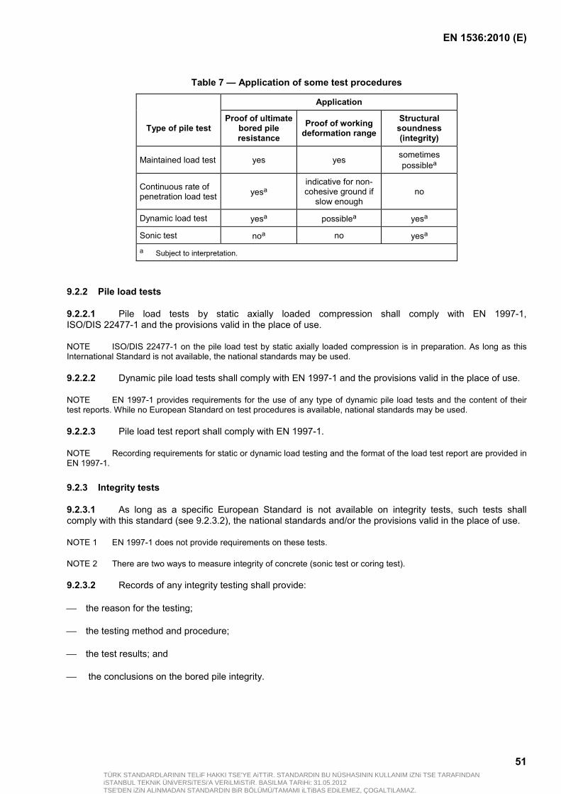
EN 1536:2010 (E)
51
Table 7 — Application of some test procedures
Application
Type of pile test Proof of ultimate
bored pile resistance
Proof of working deformation range
Structural soundness (integrity)
Maintained load test yes yes sometimes possiblea
Continuous rate of penetration load test yesa
indicative for non-cohesive ground if
slow enough no
Dynamic load test yesa possiblea yesa
Sonic test noa no yesa
a Subject to interpretation.
9.2.2 Pile load tests
9.2.2.1 Pile load tests by static axially loaded compression shall comply with EN 1997-1, ISO/DIS 22477-1 and the provisions valid in the place of use.
NOTE ISO/DIS 22477-1 on the pile load test by static axially loaded compression is in preparation. As long as this International Standard is not available, the national standards may be used.
9.2.2.2 Dynamic pile load tests shall comply with EN 1997-1 and the provisions valid in the place of use.
NOTE EN 1997-1 provides requirements for the use of any type of dynamic pile load tests and the content of their test reports. While no European Standard on test procedures is available, national standards may be used.
9.2.2.3 Pile load test report shall comply with EN 1997-1.
NOTE Recording requirements for static or dynamic load testing and the format of the load test report are provided in EN 1997-1.
9.2.3 Integrity tests
9.2.3.1 As long as a specific European Standard is not available on integrity tests, such tests shall comply with this standard (see 9.2.3.2), the national standards and/or the provisions valid in the place of use.
NOTE 1 EN 1997-1 does not provide requirements on these tests.
NOTE 2 There are two ways to measure integrity of concrete (sonic test or coring test).
9.2.3.2 Records of any integrity testing shall provide:
the reason for the testing;
the testing method and procedure;
the test results; and
the conclusions on the bored pile integrity.
TÜRK STANDARDLARININ TELiF HAKKI TSE'YE AiTTiR. STANDARDIN BU NÜSHASININ KULLANIM iZNi TSE TARAFINDANiSTANBUL TEKNiK ÜNiVERSiTESi'A VERiLMiSTiR. BASILMA TARiHi: 31.05.2012TSE'DEN iZiN ALINMADAN STANDARDIN BiR BÖLÜMÜ/TAMAMI iLTiBAS EDiLEMEZ, ÇOGALTILAMAZ.

EN 1536:2010 (E)
52
10 Records
10.1 Site records shall consist of two parts; the first making reference to the site and the general information including:
the bored pile (type, dimensions, etc.);
the construction method (including machine type); and
the reinforcement and concrete specification.
The second part shall contain particular information related to the construction procedure.
10.2 The general information part shall be similar for the different types of bored piles and methods and shall contain the details listed in Table 8 and Table 9.
10.3 The particular information part shall be specific to the type of bored pile and the construction method and shall contain the details listed in Table 10.
10.4 As appropriate, the information can be provided in the form of:
individual records compiled for each bored pile; or
summary records for groups of bored piles of the same type, constructed with the same method.
10.5 Details of recording and the format of the site records shall be agreed before the commencement of the piling.
NOTE Sample construction records are provided in Annex C (Records C.1 to C.6).
TÜRK STANDARDLARININ TELiF HAKKI TSE'YE AiTTiR. STANDARDIN BU NÜSHASININ KULLANIM iZNi TSE TARAFINDANiSTANBUL TEKNiK ÜNiVERSiTESi'A VERiLMiSTiR. BASILMA TARiHi: 31.05.2012TSE'DEN iZiN ALINMADAN STANDARDIN BiR BÖLÜMÜ/TAMAMI iLTiBAS EDiLEMEZ, ÇOGALTILAMAZ.

EN 1536:2010 (E)
53
Table 8 — General information of the site
Subject Necessity
1 site location X
2 contract identification X
3 structure X
4 main contractor (X)
5 foundation (piling) contractor X
6 client/employer (X)
7 engineer/designer (X) X: necessary information. (X): information as applicable.
Table 9 — General information of the procedure
Subject Necessity
1 pile shaft diameter/barrette size/enlargements X
2 excavation method X
3 details of support fluid X
4 cleaning method X
5 reinforcement details X
6 concrete specification X
7 concrete placement details X X: necessary information.
TÜRK STANDARDLARININ TELiF HAKKI TSE'YE AiTTiR. STANDARDIN BU NÜSHASININ KULLANIM iZNi TSE TARAFINDANiSTANBUL TEKNiK ÜNiVERSiTESi'A VERiLMiSTiR. BASILMA TARiHi: 31.05.2012TSE'DEN iZiN ALINMADAN STANDARDIN BiR BÖLÜMÜ/TAMAMI iLTiBAS EDiLEMEZ, ÇOGALTILAMAZ.

EN 1536:2010 (E)
54
Table 10 — Schedule of as-built information to be provided for a bored pile
Nr
Subject
cased/uncased excavation
excavation supported by
fluids
continuous flight auger
piles
1 Identification and as-built position
1.1 bored pile reference number X X X
1.2 depth of bored pile X X X
1.3 position deviation X X X
1.4 rake deviation X X X
2 Execution information
2.1 excavation times X X X
2.2 interruptions of excavation X X X
2.3 removal of obstructions X X —
2.4 temporary/permanent casing X — —
2.5 depth of casing X — —
2.6 lead-in tube/guide wall — X (X)
2.7 depth of lead-in tube — X (X)
2.8 cleaning X X —
2.9 recovery of casing X — —
2.10 recovery of lead-in tube — X (X)
2.11 backfilling empty bore X X X
3 Ground conditions
3.1 drilling log X X (X)
3.2 ground water table X X (X)
4 Support fluid
4.1 properties — X —
4.2 properties at re-used stage — X —
5 Concreting information
5.1 concrete placement
5.2 dry/submerged conditions X X —
5.3 duration X X X
5.4 interruptions X X X
5.5 volume X X X
5.6 pressure — — X
5.7 site tests X X X
6 Reinforcement
5.1 length X X X
5.2 suspension bar X X X
5.3 installation time X X X
7 Precast concrete elements
TÜRK STANDARDLARININ TELiF HAKKI TSE'YE AiTTiR. STANDARDIN BU NÜSHASININ KULLANIM iZNi TSE TARAFINDANiSTANBUL TEKNiK ÜNiVERSiTESi'A VERiLMiSTiR. BASILMA TARiHi: 31.05.2012TSE'DEN iZiN ALINMADAN STANDARDIN BiR BÖLÜMÜ/TAMAMI iLTiBAS EDiLEMEZ, ÇOGALTILAMAZ.
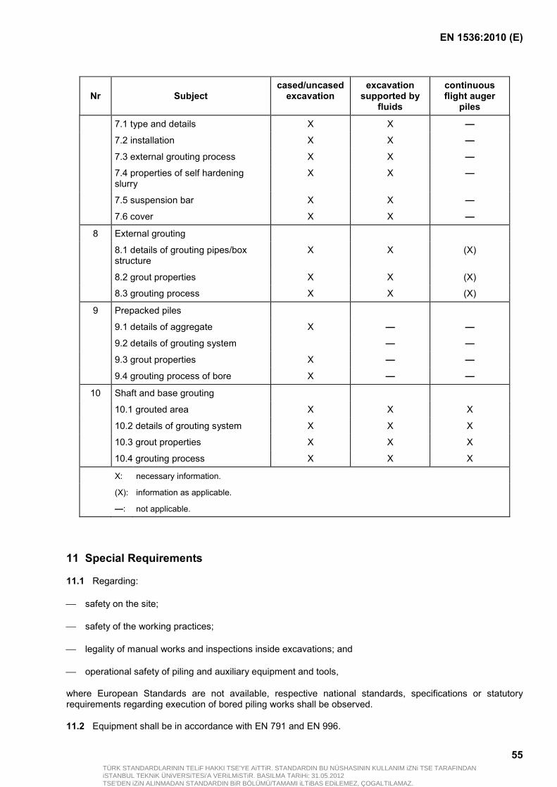
EN 1536:2010 (E)
55
Nr
Subject
cased/uncased excavation
excavation supported by
fluids
continuous flight auger
piles
7.1 type and details X X —
7.2 installation X X —
7.3 external grouting process X X —
7.4 properties of self hardening slurry
X X —
7.5 suspension bar X X —
7.6 cover X X —
8 External grouting
8.1 details of grouting pipes/box structure
X X (X)
8.2 grout properties X X (X)
8.3 grouting process X X (X)
9 Prepacked piles
9.1 details of aggregate X — —
9.2 details of grouting system — —
9.3 grout properties X — —
9.4 grouting process of bore X — —
10 Shaft and base grouting
10.1 grouted area X X X
10.2 details of grouting system X X X
10.3 grout properties X X X
10.4 grouting process X X X
X: necessary information.
(X): information as applicable.
—: not applicable.
11 Special Requirements
11.1 Regarding:
safety on the site;
safety of the working practices;
legality of manual works and inspections inside excavations; and
operational safety of piling and auxiliary equipment and tools,
where European Standards are not available, respective national standards, specifications or statutory requirements regarding execution of bored piling works shall be observed.
11.2 Equipment shall be in accordance with EN 791 and EN 996.
TÜRK STANDARDLARININ TELiF HAKKI TSE'YE AiTTiR. STANDARDIN BU NÜSHASININ KULLANIM iZNi TSE TARAFINDANiSTANBUL TEKNiK ÜNiVERSiTESi'A VERiLMiSTiR. BASILMA TARiHi: 31.05.2012TSE'DEN iZiN ALINMADAN STANDARDIN BiR BÖLÜMÜ/TAMAMI iLTiBAS EDiLEMEZ, ÇOGALTILAMAZ.

EN 1536:2010 (E)
56
11.3 Particular attention shall be drawn to:
all processes requiring men operating alongside heavy equipment and heavy tools;
the danger of open bore holes;
manual working procedures and inspections carried out inside excavations.
11.4 Excavation by hand should be kept to a minimum.
11.5 Excavation by hand shall be restricted to dry conditions where the ground is naturally stable or where support of the excavation walls is continuously being maintained.
11.6 When permitted, employment (see 11.1) of personnel inside a bore is allowed only if the available space for the work is at least 0,75 m in diameter.
11.7 Nuisance and/or environmental damage that can be caused by piling work shall be kept to a minimum.
11.8 Such nuisance and/or environmental damage can be caused by:
noise;
ground vibration;
ground pollution;
surface water pollution;
groundwater pollution; and
air pollution.
NOTE The type and extent of possible nuisance or environmental impact depends on:
— the location;
— the working method;
— the actual processes.
11.9 Where respective European Standards are not available regarding nuisance and environmental protection, national and local requirements shall be observed.
11.10 Rejected materials shall be removed promptly from the site in accordance with national and local requirements.
TÜRK STANDARDLARININ TELiF HAKKI TSE'YE AiTTiR. STANDARDIN BU NÜSHASININ KULLANIM iZNi TSE TARAFINDANiSTANBUL TEKNiK ÜNiVERSiTESi'A VERiLMiSTiR. BASILMA TARiHi: 31.05.2012TSE'DEN iZiN ALINMADAN STANDARDIN BiR BÖLÜMÜ/TAMAMI iLTiBAS EDiLEMEZ, ÇOGALTILAMAZ.
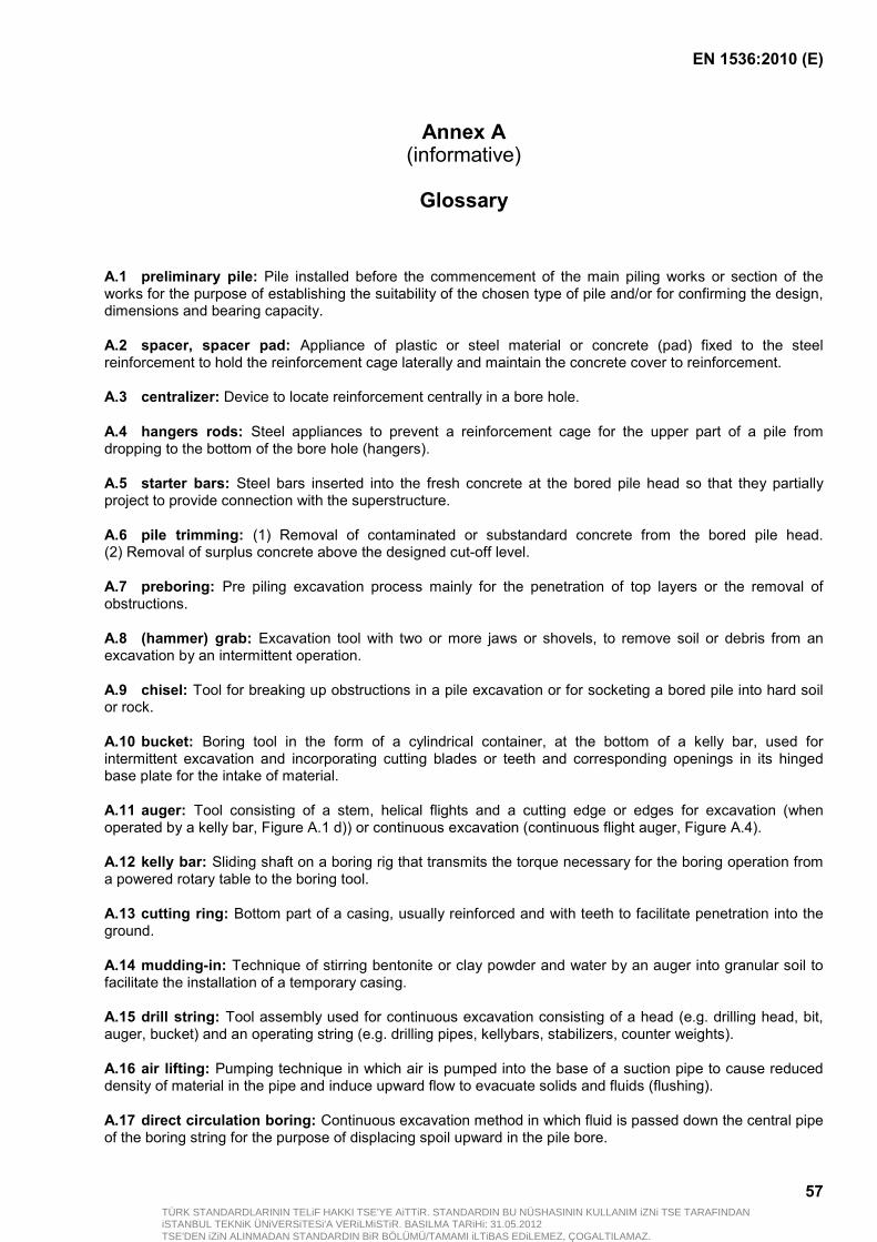
EN 1536:2010 (E)
57
Annex A (informative)
Glossary
A.1 preliminary pile: Pile installed before the commencement of the main piling works or section of the works for the purpose of establishing the suitability of the chosen type of pile and/or for confirming the design, dimensions and bearing capacity.
A.2 spacer, spacer pad: Appliance of plastic or steel material or concrete (pad) fixed to the steel reinforcement to hold the reinforcement cage laterally and maintain the concrete cover to reinforcement.
A.3 centralizer: Device to locate reinforcement centrally in a bore hole.
A.4 hangers rods: Steel appliances to prevent a reinforcement cage for the upper part of a pile from dropping to the bottom of the bore hole (hangers).
A.5 starter bars: Steel bars inserted into the fresh concrete at the bored pile head so that they partially project to provide connection with the superstructure.
A.6 pile trimming: (1) Removal of contaminated or substandard concrete from the bored pile head. (2) Removal of surplus concrete above the designed cut-off level.
A.7 preboring: Pre piling excavation process mainly for the penetration of top layers or the removal of obstructions.
A.8 (hammer) grab: Excavation tool with two or more jaws or shovels, to remove soil or debris from an excavation by an intermittent operation.
A.9 chisel: Tool for breaking up obstructions in a pile excavation or for socketing a bored pile into hard soil or rock.
A.10 bucket: Boring tool in the form of a cylindrical container, at the bottom of a kelly bar, used for intermittent excavation and incorporating cutting blades or teeth and corresponding openings in its hinged base plate for the intake of material.
A.11 auger: Tool consisting of a stem, helical flights and a cutting edge or edges for excavation (when operated by a kelly bar, Figure A.1 d)) or continuous excavation (continuous flight auger, Figure A.4).
A.12 kelly bar: Sliding shaft on a boring rig that transmits the torque necessary for the boring operation from a powered rotary table to the boring tool.
A.13 cutting ring: Bottom part of a casing, usually reinforced and with teeth to facilitate penetration into the ground.
A.14 mudding-in: Technique of stirring bentonite or clay powder and water by an auger into granular soil to facilitate the installation of a temporary casing.
A.15 drill string: Tool assembly used for continuous excavation consisting of a head (e.g. drilling head, bit, auger, bucket) and an operating string (e.g. drilling pipes, kellybars, stabilizers, counter weights).
A.16 air lifting: Pumping technique in which air is pumped into the base of a suction pipe to cause reduced density of material in the pipe and induce upward flow to evacuate solids and fluids (flushing).
A.17 direct circulation boring: Continuous excavation method in which fluid is passed down the central pipe of the boring string for the purpose of displacing spoil upward in the pile bore.
TÜRK STANDARDLARININ TELiF HAKKI TSE'YE AiTTiR. STANDARDIN BU NÜSHASININ KULLANIM iZNi TSE TARAFINDANiSTANBUL TEKNiK ÜNiVERSiTESi'A VERiLMiSTiR. BASILMA TARiHi: 31.05.2012TSE'DEN iZiN ALINMADAN STANDARDIN BiR BÖLÜMÜ/TAMAMI iLTiBAS EDiLEMEZ, ÇOGALTILAMAZ.
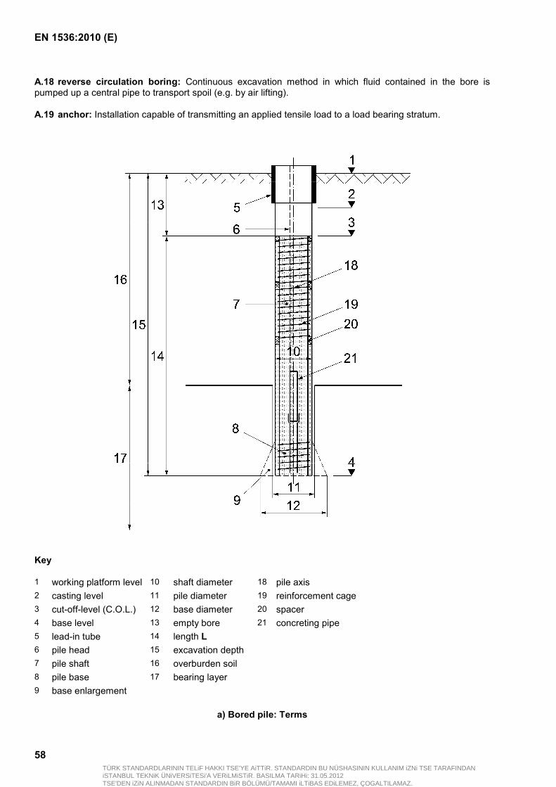
EN 1536:2010 (E)
58
A.18 reverse circulation boring: Continuous excavation method in which fluid contained in the bore is pumped up a central pipe to transport spoil (e.g. by air lifting).
A.19 anchor: Installation capable of transmitting an applied tensile load to a load bearing stratum.
Key
1 working platform level 10 shaft diameter 18 pile axis 2 casting level 11 pile diameter 19 reinforcement cage 3 cut-off-level (C.O.L.) 12 base diameter 20 spacer 4 base level 13 empty bore 21 concreting pipe 5 lead-in tube 14 length L 6 pile head 15 excavation depth 7 pile shaft 16 overburden soil 8 pile base 17 bearing layer 9 base enlargement
a) Bored pile: Terms
TÜRK STANDARDLARININ TELiF HAKKI TSE'YE AiTTiR. STANDARDIN BU NÜSHASININ KULLANIM iZNi TSE TARAFINDANiSTANBUL TEKNiK ÜNiVERSiTESi'A VERiLMiSTiR. BASILMA TARiHi: 31.05.2012TSE'DEN iZiN ALINMADAN STANDARDIN BiR BÖLÜMÜ/TAMAMI iLTiBAS EDiLEMEZ, ÇOGALTILAMAZ.
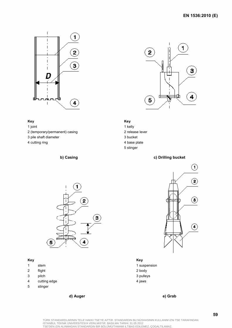
EN 1536:2010 (E)
59
Key 1 joint
Key1 kelly
2 (temporary/permanent) casing 2 release lever 3 pile shaft diameter 3 bucket 4 cutting ring 4 base plate 5 stinger
b) Casing c) Drilling bucket
Key 1
stem
Key1 suspension
2 flight 2 body 3 pitch 3 pulleys 4 cutting edge 4 jaws 5 stinger
d) Auger e) Grab
TÜRK STANDARDLARININ TELiF HAKKI TSE'YE AiTTiR. STANDARDIN BU NÜSHASININ KULLANIM iZNi TSE TARAFINDANiSTANBUL TEKNiK ÜNiVERSiTESi'A VERiLMiSTiR. BASILMA TARiHi: 31.05.2012TSE'DEN iZiN ALINMADAN STANDARDIN BiR BÖLÜMÜ/TAMAMI iLTiBAS EDiLEMEZ, ÇOGALTILAMAZ.

EN 1536:2010 (E)
60
Key
1 chisel body 2 tip
f) Chisel
Figure A.1 — Tools for discontinuous excavation
Key
1 working platform level 6 drilling bit 2 power swivel 7 mud pit 3 casing/lead-in tube 8 cuttings 4 drill string 9 from the pump
Figure A.2 — Direct circulation boring system
TÜRK STANDARDLARININ TELiF HAKKI TSE'YE AiTTiR. STANDARDIN BU NÜSHASININ KULLANIM iZNi TSE TARAFINDANiSTANBUL TEKNiK ÜNiVERSiTESi'A VERiLMiSTiR. BASILMA TARiHi: 31.05.2012TSE'DEN iZiN ALINMADAN STANDARDIN BiR BÖLÜMÜ/TAMAMI iLTiBAS EDiLEMEZ, ÇOGALTILAMAZ.
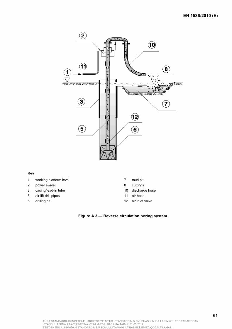
EN 1536:2010 (E)
61
Key
1 working platform level 7 mud pit 2 power swivel 8 cuttings 3 casing/lead-in tube 10 discharge hose 5 air lift drill pipes 11 air hose 6 drilling bit 12 air inlet valve
Figure A.3 — Reverse circulation boring system
TÜRK STANDARDLARININ TELiF HAKKI TSE'YE AiTTiR. STANDARDIN BU NÜSHASININ KULLANIM iZNi TSE TARAFINDANiSTANBUL TEKNiK ÜNiVERSiTESi'A VERiLMiSTiR. BASILMA TARiHi: 31.05.2012TSE'DEN iZiN ALINMADAN STANDARDIN BiR BÖLÜMÜ/TAMAMI iLTiBAS EDiLEMEZ, ÇOGALTILAMAZ.

EN 1536:2010 (E)
62
a) Boring b) Concreting Key 1 thrust cylinder 7 hollow stem 2 mast 8 bung 3 working platform level 9 concrete supply 4 pitch 10 spoil 5 spoil 11 concrete 6 continuous flight auger
Figure A.4 — Continuous flight auger drilling
TÜRK STANDARDLARININ TELiF HAKKI TSE'YE AiTTiR. STANDARDIN BU NÜSHASININ KULLANIM iZNi TSE TARAFINDANiSTANBUL TEKNiK ÜNiVERSiTESi'A VERiLMiSTiR. BASILMA TARiHi: 31.05.2012TSE'DEN iZiN ALINMADAN STANDARDIN BiR BÖLÜMÜ/TAMAMI iLTiBAS EDiLEMEZ, ÇOGALTILAMAZ.
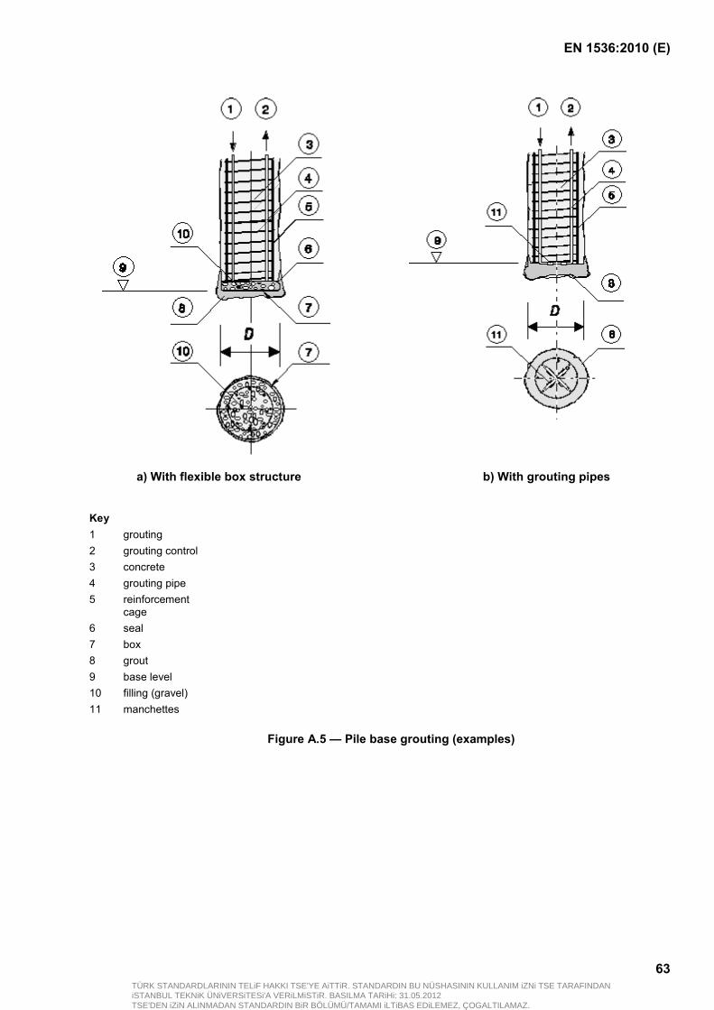
EN 1536:2010 (E)
63
a) With flexible box structure b) With grouting pipes
Key 1 grouting 2 grouting control 3 concrete 4 grouting pipe 5 reinforcement
cage 6 seal 7 box 8 grout 9 base level 10 filling (gravel) 11 manchettes
Figure A.5 — Pile base grouting (examples)
TÜRK STANDARDLARININ TELiF HAKKI TSE'YE AiTTiR. STANDARDIN BU NÜSHASININ KULLANIM iZNi TSE TARAFINDANiSTANBUL TEKNiK ÜNiVERSiTESi'A VERiLMiSTiR. BASILMA TARiHi: 31.05.2012TSE'DEN iZiN ALINMADAN STANDARDIN BiR BÖLÜMÜ/TAMAMI iLTiBAS EDiLEMEZ, ÇOGALTILAMAZ.
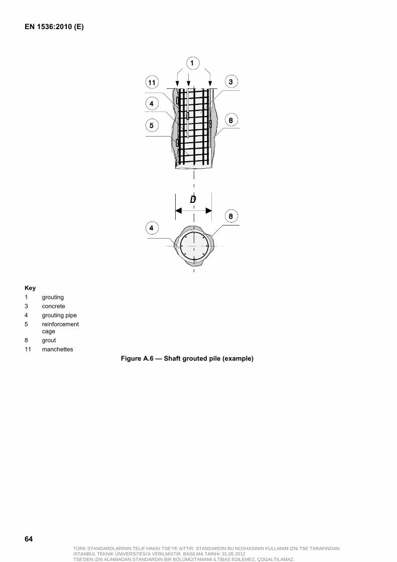
EN 1536:2010 (E)
64
Key 1 grouting 3 concrete 4 grouting pipe 5 reinforcement
cage 8 grout 11 manchettes
Figure A.6 — Shaft grouted pile (example)
TÜRK STANDARDLARININ TELiF HAKKI TSE'YE AiTTiR. STANDARDIN BU NÜSHASININ KULLANIM iZNi TSE TARAFINDANiSTANBUL TEKNiK ÜNiVERSiTESi'A VERiLMiSTiR. BASILMA TARiHi: 31.05.2012TSE'DEN iZiN ALINMADAN STANDARDIN BiR BÖLÜMÜ/TAMAMI iLTiBAS EDiLEMEZ, ÇOGALTILAMAZ.
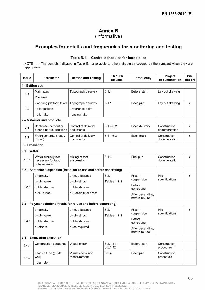
EN 1536:2010 (E)
65
Annex B (informative)
Examples for details and frequencies for monitoring and testing
Table B.1 — Control schedules for bored piles NOTE The controls indicated in Table B.1 also apply to others structures covered by the standard when they are appropriate.
Issue Parameter Method and Testing EN 1536 clauses Frequency Project
documentation Pile
Report
1 - Setting out
1.1 Main axes
Pile axes
Topographic survey 8.1.1 Before start Lay out drawing
1.2
- working platform level
- pile position
- pile rake
Topographic survey
- reference point
- casing rake
8.1.1 Each pile Lay out drawing x
2 – Materials and products
2.1 Bentonite, cement or other binders, additions
Control of delivery documents
6.1 – 6.2 Each delivery Construction documentation
x
2.2 Fresh concrete (ready mixed)
Control of delivery documents
6.1 – 6.3 Each truck Construction documentation
x
3 – Excavation
3.1 – Water
3.1.1 Water (usually not necessary for tap / potable water)
Mixing of test suspension
6.1.6 First pile Construction documentation
x
3.2 – Bentonite suspension (fresh, for re-use and before concreting)
3.2.1
a) density
b) pH-value
c) Marsh-time
d) fluid loss
a) mud balance
b) pH-strips
c) Marsh cone
d) Baroid filter press
6.2.1
Tables 1 & 2
Fresh suspension
Before concreting
After desanding, before re-use
Pile specifications
x
3.3 – Polymer solutions (fresh, for re-use and before concreting)
3.3.1
a) density
b) pH-value
c) Marsh-time
d) others
a) mud balance
b) pH-strips
c) Marsh cone
d) as required
6.2.1
Tables 1 & 2
Fresh suspension
Before concreting
After desanding, before re-use
Pile specifications
x
3.4 – Excavation execution
3.4.1 Construction sequence Visual check 8.2.1.11 - 8.2.1.12
Before start Construction procedure
3.4.2 Lead-in tube (guide wall)
- diameter
Visual check and measurement
8.2.4 Each pile Construction procedure
TÜRK STANDARDLARININ TELiF HAKKI TSE'YE AiTTiR. STANDARDIN BU NÜSHASININ KULLANIM iZNi TSE TARAFINDANiSTANBUL TEKNiK ÜNiVERSiTESi'A VERiLMiSTiR. BASILMA TARiHi: 31.05.2012TSE'DEN iZiN ALINMADAN STANDARDIN BiR BÖLÜMÜ/TAMAMI iLTiBAS EDiLEMEZ, ÇOGALTILAMAZ.

EN 1536:2010 (E)
66
- width
- level, depth
3.4.3
Use of tools (general)
- type of tool
- chisel
- tool changes
Visual check 8.2.2 Each pile Construction procedure
3.4.4
Installation of casings and advancement
- number
- length
- depth
Visual check and measurement
8.2.3 Continuously Construction procedure
3.4.5 Suspension level and excess fluid pressure
Visual check and measurement
8.2.3.6 – 8.2.4.6 Continuously Construction procedure
3.4.6
Excavated material
Socket
Visual check
Visual check or sample
7.3 – 9.1.6 Continuously
As required
Soil investigation report
Pile specification (socketed pile)
3.4.7 Pile depth Plummet Each pile Pile specifications
x
3.4.8
Pile enlargement
- depth
- type of tool
Visual check and measurement
8.2.7 Each enlargement
Pile specifications
x
3.4.9 Cleaning of base Sounding 8.2.1.13 Each pile Pile specifications
x
4 – Reinforcement cages
4.1 – Delivery
4.1.1
- length
- bars
- assembly
- stiffness
- spacers
- lining
Visual check and measurement
8.3 Each cage Drawing
Certificate
x
4.2 – Installation
4.2.1
Installation of cages
- depth
- position
- overlap
Measurement 8.3 Each cage
4.3 – Special items (pipes for sonic logging, monitoring devices, box-outs)
4.3.1
- position
- depth
- connections with cage
- protection during installation
- protection during concrete placement
Visual check and measurement
6.5 Each cage
TÜRK STANDARDLARININ TELiF HAKKI TSE'YE AiTTiR. STANDARDIN BU NÜSHASININ KULLANIM iZNi TSE TARAFINDANiSTANBUL TEKNiK ÜNiVERSiTESi'A VERiLMiSTiR. BASILMA TARiHi: 31.05.2012TSE'DEN iZiN ALINMADAN STANDARDIN BiR BÖLÜMÜ/TAMAMI iLTiBAS EDiLEMEZ, ÇOGALTILAMAZ.

EN 1536:2010 (E)
67
5 – Concreting and trimming
5.1 – Concrete (ready mixed)
5.1.1 Concrete Delivery document Each truck Specifications
5.1.2 Sampling Cylinder, cube 6.3.8 See 6.3.8 x
5.1.3
Consistence Visual check and Slump or Flow test
6.3.6.3 – Table 4 Each truck (visual check)
Spot checks (slump or flow)
Delivery document
x
5.1.4 Workability time Change of slump or
Flow value 6.3.6.4 First pile
Spot checks
x
5.2 – Concrete placement
5.2.1
Level of head of concrete
Measurement (record level)
Above cut-off level
Each pile and after:
- each truck
- casing recovery
- concreting
Specifications x
5.2.2 Immersion of tremie pipe
Measurement (record length)
8.4.3.15 – 8.4.3.16
Each truck x
5.2.3 Concrete volume Measurement (record volumes)
Each pile x
5.3 – Trimming
5.3.1 Concrete at cut-off level
Unconfined compressive strength
8.1.3 Each pile Specifications
End of Table B.1
TÜRK STANDARDLARININ TELiF HAKKI TSE'YE AiTTiR. STANDARDIN BU NÜSHASININ KULLANIM iZNi TSE TARAFINDANiSTANBUL TEKNiK ÜNiVERSiTESi'A VERiLMiSTiR. BASILMA TARiHi: 31.05.2012TSE'DEN iZiN ALINMADAN STANDARDIN BiR BÖLÜMÜ/TAMAMI iLTiBAS EDiLEMEZ, ÇOGALTILAMAZ.
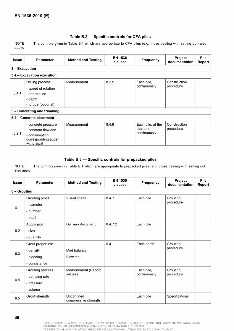
EN 1536:2010 (E)
68
Table B.2 — Specific controls for CFA piles NOTE The controls given in Table B.1 which are appropriate to CFA piles (e.g. those dealing with setting out) also apply.
Issue Parameter Method and Testing EN 1536 clauses Frequency Project
documentation Pile
Report
3 – Excavation
3.4 – Excavation execution
3.4.1
Drilling process
- speed of rotation - penetration - depth - torque (optional)
Measurement 8.2.5 Each pile, continuously
Construction procedure
5 – Concreting and trimming
5.2 – Concrete placement
5.2.1
- concrete pressure - concrete flow and - consumption corresponding auger withdrawal
Measurement 8.4.6 Each pile, at the start and continuously
Construction procedure
Table B.3 — Specific controls for prepacked piles
NOTE The controls given in Table B.1 which are appropriate to prepacked piles (e.g. those dealing with setting out) also apply.
Issue Parameter Method and Testing EN 1536 clauses Frequency Project
documentation Pile
Report
6 – Grouting
6.1
Grouting pipes:
- diameter
- number
- depth
Visual check 8.4.7 Each pile Grouting procedure
6.2
Aggregate:
- size
- quantity
Delivery document 8.4.7.2 Each pile
6.3
Grout properties:
- density
- bleeding
- consistence
Mud balance
Flow test
6.4 Each batch Grouting procedure
6.4
Grouting process
- pumping rate
- pressure
- volume
Measurement (Record values)
Each pile, continuously
Grouting procedure
6.5 Grout strength Unconfined compressive strength
Each pile Specifications
TÜRK STANDARDLARININ TELiF HAKKI TSE'YE AiTTiR. STANDARDIN BU NÜSHASININ KULLANIM iZNi TSE TARAFINDANiSTANBUL TEKNiK ÜNiVERSiTESi'A VERiLMiSTiR. BASILMA TARiHi: 31.05.2012TSE'DEN iZiN ALINMADAN STANDARDIN BiR BÖLÜMÜ/TAMAMI iLTiBAS EDiLEMEZ, ÇOGALTILAMAZ.

EN 1536:2010 (E)
69
Table B.4 — Specific controls for external grouting and of shaft/base grouting
Issue Parameter Method and Testing EN 1536 clauses Frequency Project
documentation Pile
Report
6 – Grouting
6.1
Grouting pipes:
- number
- diameter
- number of valves
Visual check 8.4.10 Each pile Grouting procedure
6.2
Box structure (flexible)
- position
- fixation
Visual check 8.4.10 Each pile Grouting procedure
6.3
Grouting process
- fracturing time
- pumping rate
- pressure
- consumption
- distribution of grout
Measurement (Record values)
8.4.10 Each pile, continuously
Grouting procedure
TÜRK STANDARDLARININ TELiF HAKKI TSE'YE AiTTiR. STANDARDIN BU NÜSHASININ KULLANIM iZNi TSE TARAFINDANiSTANBUL TEKNiK ÜNiVERSiTESi'A VERiLMiSTiR. BASILMA TARiHi: 31.05.2012TSE'DEN iZiN ALINMADAN STANDARDIN BiR BÖLÜMÜ/TAMAMI iLTiBAS EDiLEMEZ, ÇOGALTILAMAZ.

EN 1536:2010 (E)
70
Annex C (informative)
Sample records
This annex contains sample construction records for:
bored piles with cased or unsupported excavation (EXAMPLE: C.1 and EXAMPLE: C.2);
bored piles constructed with support fluids (EXAMPLE: C.3 and EXAMPLE: C.4);
continuous flight auger piles (EXAMPLE: C.5 and EXAMPLE: C.6).
The records C.1 to C.6 can be supplemented by additional forms as applicable, such as:
survey records;
support fluid control records;
concrete mixing records (in cases of site mixing only);
delivery documents for concrete and/or grout;
consistency, temperature and workability tests on site for concrete and for grout;
concrete placement records;
grouting records;
cut-off inspection forms.
TÜRK STANDARDLARININ TELiF HAKKI TSE'YE AiTTiR. STANDARDIN BU NÜSHASININ KULLANIM iZNi TSE TARAFINDANiSTANBUL TEKNiK ÜNiVERSiTESi'A VERiLMiSTiR. BASILMA TARiHi: 31.05.2012TSE'DEN iZiN ALINMADAN STANDARDIN BiR BÖLÜMÜ/TAMAMI iLTiBAS EDiLEMEZ, ÇOGALTILAMAZ.
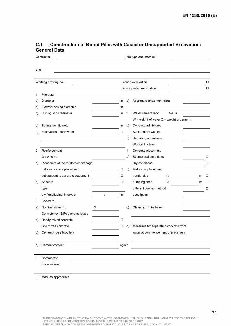
EN 1536:2010 (E)
71
C.1 — Construction of Bored Piles with Cased or Unsupported Excavation: General Data Contractor Pile type and method
Site
Working drawing no. cased excavation
unsupported excavation
1 Pile data
a) Diameter m e) Aggregate (maximum size)
b) External casing diameter m
c) Cutting shoe diameter m f) Water cement ratio W/C =
W = weight of water C = weight of cement
d) Boring tool diameter m g) Concrete admixtures
e) Excavation under water % of cement weight
h) Retarding admixtures
Workability time
2 Reinforcement 4 Concrete placement
Drawing no. a) Submerged conditions
a) Placement of the reinforcement cage Dry conditions
before concrete placement b) Method of placement
subsequent to concrete placement tremie pipe ∅ m
b) Spacers pumping hose ∅ m
type different placing method
qty./longitudinal intervals / m description
3 Concrete
a) Nominal strength: C c) Cleaning of pile base
Consistency: S/F/superplasticized
b) Ready-mixed concrete
Site mixed concrete d) Measures for separating concrete from
c) Cement type (Supplier) water at commencement of placement
d) Cement content kg/m³
5 Comments/
observations
Mark as appropriate
TÜRK STANDARDLARININ TELiF HAKKI TSE'YE AiTTiR. STANDARDIN BU NÜSHASININ KULLANIM iZNi TSE TARAFINDANiSTANBUL TEKNiK ÜNiVERSiTESi'A VERiLMiSTiR. BASILMA TARiHi: 31.05.2012TSE'DEN iZiN ALINMADAN STANDARDIN BiR BÖLÜMÜ/TAMAMI iLTiBAS EDiLEMEZ, ÇOGALTILAMAZ.

EN 1536:2010 (E)
72
C.2 — Construction of Bored Piles with Cased or Unsupported Excavations : Particular Data
Bored pile no. Compression pile
Tension pile
Rake
1 Ground strata
m below working platform level
m above principal datum
Ground description
Ground-water
Boring tool casing from ............... to .............. m
working platform level ± 0 ∇ Scale 1:
2 Times of execution
1 2 3 4 5
Process
Ambient temperature
Times
Date
°C from to Excavation Chiselling Interruption Base formation
Concrete placement
Mark as appropriate
3 Pile data a) Depth measurement after excavation m below working platform level b) chiselling: from m to m below working platform level c) Deviation of position at working platform level Axis: : cm Axis: : cm
4 Reinforcement Deviations from drawing no. Deviations along length Modifications
5 Concrete Special events
6 Concrete placement Water level inside the bore at start of placement below working platform level m Concrete consumption Theoretical m³ Actual m³
7 Comments/observations Deviations from general data
8 Signatures/date Foreman/superintendent Contractor's representative Client's representative
TÜRK STANDARDLARININ TELiF HAKKI TSE'YE AiTTiR. STANDARDIN BU NÜSHASININ KULLANIM iZNi TSE TARAFINDANiSTANBUL TEKNiK ÜNiVERSiTESi'A VERiLMiSTiR. BASILMA TARiHi: 31.05.2012TSE'DEN iZiN ALINMADAN STANDARDIN BiR BÖLÜMÜ/TAMAMI iLTiBAS EDiLEMEZ, ÇOGALTILAMAZ.

EN 1536:2010 (E)
73
C.3 — Construction of Bored Piles with Support Fluids: General Data Contractor Pile type and method
Site
Working drawing no.
1 Pile data a) Diameter of pile/barrette m e) Aggregate (maximum size)
b) Dimension of guide wall or lead-in tube m
c) Excavation tool f) Water cement ratio W/C =
W = weight of water C = weight of cement
g) Concrete admixtures
d) External dimensions % of cement weight
of the excavation tool m h) Retarding admixtures
of the cutting shoe m Workability time
2 Reinforcement 4 Concrete placement Drawing no. a) Submerged conditions
a) Placement of the reinforcement cage Dry conditions
before concrete placement b) Method of placement
subsequent to concrete placement tremie pipe ∅ m
b) Spacers pumping hose ∅ m
type different placing method
qty./longitudinal intervals / m description
3 Concrete a) Nominal strength: C c) Cleaning of pile base
Consistency: S/F/superplasticized
b) Ready-mixed concrete
Site mixed concrete d) Measures for separating concrete from
c) Cement type (Supplier) water at commencement of placement
d) Cement content kg/m³
5 Comments/ observations
Mark as appropriate
TÜRK STANDARDLARININ TELiF HAKKI TSE'YE AiTTiR. STANDARDIN BU NÜSHASININ KULLANIM iZNi TSE TARAFINDANiSTANBUL TEKNiK ÜNiVERSiTESi'A VERiLMiSTiR. BASILMA TARiHi: 31.05.2012TSE'DEN iZiN ALINMADAN STANDARDIN BiR BÖLÜMÜ/TAMAMI iLTiBAS EDiLEMEZ, ÇOGALTILAMAZ.
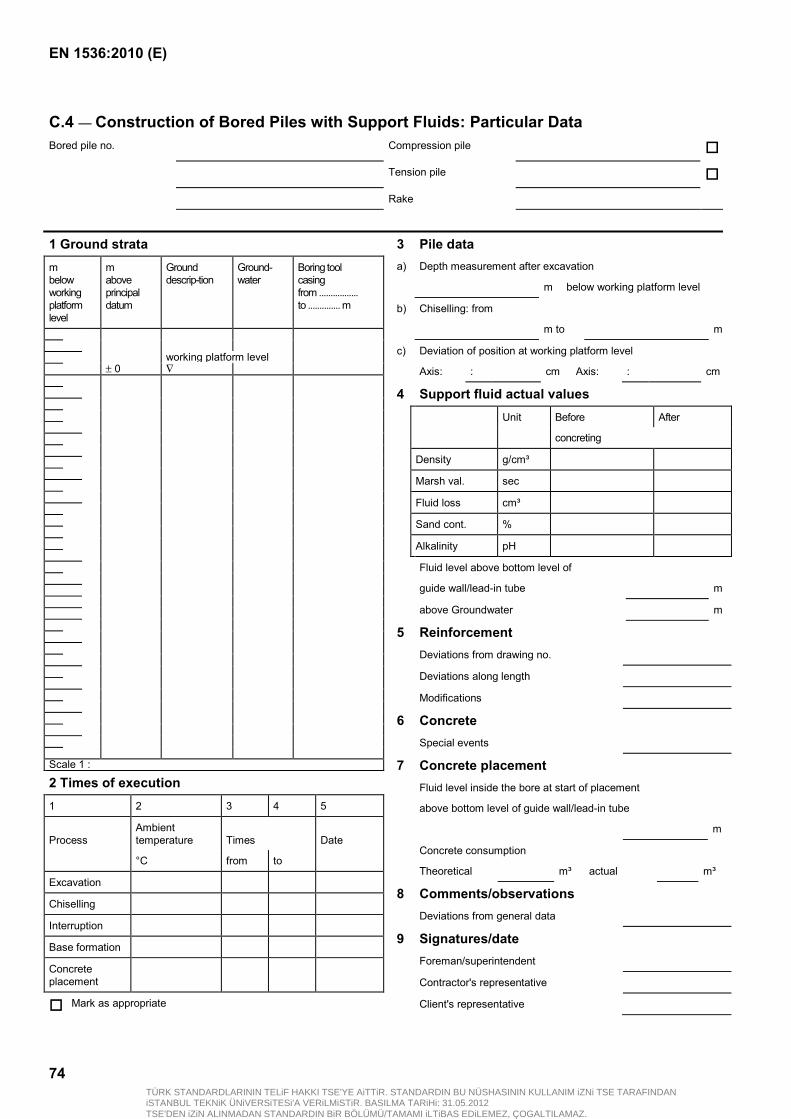
EN 1536:2010 (E)
74
C.4 — Construction of Bored Piles with Support Fluids: Particular Data Bored pile no. Compression pile
Tension pile
Rake
1 Ground strata m below working platform level
m above principal datum
Ground descrip-tion
Ground-water
Boring tool casing from ................. to .............. m
working platform level ± 0 ∇ Scale 1 :
2 Times of execution 1 2 3 4 5
Process
Ambient temperature
Times
Date
°C from to
Excavation
Chiselling
Interruption
Base formation
Concrete placement
Mark as appropriate
3 Pile data a) Depth measurement after excavation
m below working platform level
b) Chiselling: from
m to m
c) Deviation of position at working platform level
Axis: : cm Axis: : cm
4 Support fluid actual values Unit Before After
concreting
Density g/cm³
Marsh val. sec
Fluid loss cm³
Sand cont. %
Alkalinity pH
Fluid level above bottom level of
guide wall/lead-in tube m
above Groundwater m
5 Reinforcement Deviations from drawing no.
Deviations along length
Modifications
6 Concrete Special events
7 Concrete placement Fluid level inside the bore at start of placement
above bottom level of guide wall/lead-in tube
m
Concrete consumption
Theoretical m³ actual m³
8 Comments/observations Deviations from general data
9 Signatures/date Foreman/superintendent
Contractor's representative
Client's representative
TÜRK STANDARDLARININ TELiF HAKKI TSE'YE AiTTiR. STANDARDIN BU NÜSHASININ KULLANIM iZNi TSE TARAFINDANiSTANBUL TEKNiK ÜNiVERSiTESi'A VERiLMiSTiR. BASILMA TARiHi: 31.05.2012TSE'DEN iZiN ALINMADAN STANDARDIN BiR BÖLÜMÜ/TAMAMI iLTiBAS EDiLEMEZ, ÇOGALTILAMAZ.
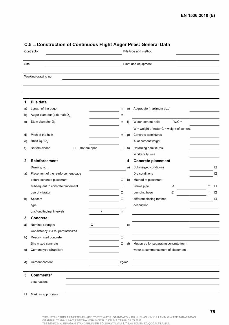
EN 1536:2010 (E)
75
C.5 — Construction of Continuous Flight Auger Piles: General Data Contractor Pile type and method
Site Plant and equipment
Working drawing no.
1 Pile data a) Length of the auger m e) Aggregate (maximum size)
b) Auger diameter (external) Da m
c) Stem diameter Di m f) Water cement ratio W/C =
W = weight of water C = weight of cement
d) Pitch of the helix m g) Concrete admixtures
e) Ratio Di / Da % of cement weight
f) Bottom closed Bottom open h) Retarding admixtures
Workability time
2 Reinforcement 4 Concrete placement Drawing no. a) Submerged conditions
a) Placement of the reinforcement cage Dry conditions
before concrete placement b) Method of placement
subsequent to concrete placement tremie pipe ∅ m
use of vibrator pumping hose ∅ m
b) Spacers different placing method
type description
qty./longitudinal intervals / m
3 Concrete a) Nominal strength: C c)
Consistency: S/F/superplasticized
b) Ready-mixed concrete
Site mixed concrete d) Measures for separating concrete from
c) Cement type (Supplier) water at commencement of placement
d) Cement content kg/m³
5 Comments/ observations
Mark as appropriate
TÜRK STANDARDLARININ TELiF HAKKI TSE'YE AiTTiR. STANDARDIN BU NÜSHASININ KULLANIM iZNi TSE TARAFINDANiSTANBUL TEKNiK ÜNiVERSiTESi'A VERiLMiSTiR. BASILMA TARiHi: 31.05.2012TSE'DEN iZiN ALINMADAN STANDARDIN BiR BÖLÜMÜ/TAMAMI iLTiBAS EDiLEMEZ, ÇOGALTILAMAZ.
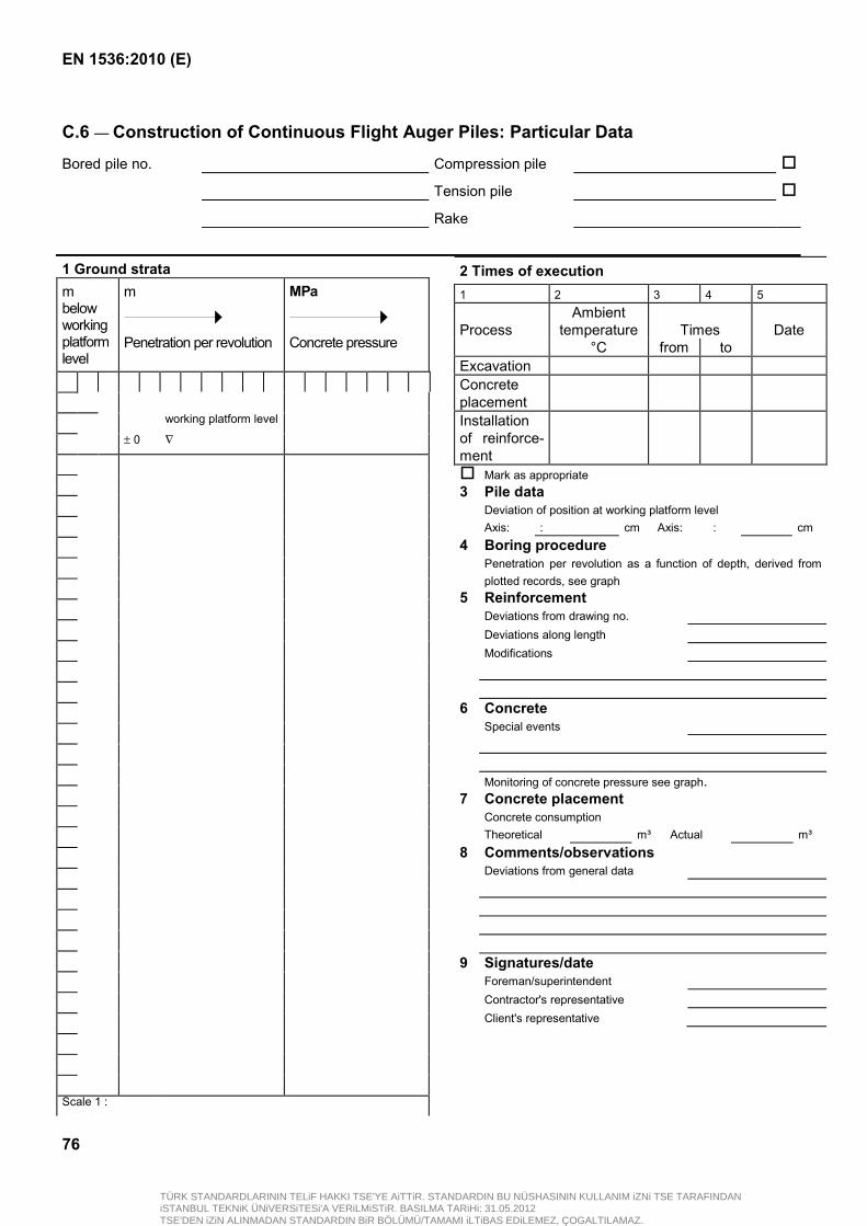
EN 1536:2010 (E)
76
C.6 — Construction of Continuous Flight Auger Piles: Particular Data
Bored pile no. Compression pile
Tension pile
Rake
1 Ground strata m below working platform level
m
Penetration per revolution
MPa
Concrete pressure
working platform level
± 0 ∇
Scale 1 :
2 Times of execution 1 2 3 4 5 Process
Ambient temperature
Times
Date
°C from to Excavation Concrete placement
Installation of reinforce-ment
Mark as appropriate 3 Pile data Deviation of position at working platform level Axis: : cm Axis: : cm 4 Boring procedure Penetration per revolution as a function of depth, derived from
plotted records, see graph 5 Reinforcement Deviations from drawing no. Deviations along length Modifications 6 Concrete Special events Monitoring of concrete pressure see graph. 7 Concrete placement Concrete consumption Theoretical m³ Actual m³ 8 Comments/observations Deviations from general data 9 Signatures/date Foreman/superintendent Contractor's representative Client's representative
TÜRK STANDARDLARININ TELiF HAKKI TSE'YE AiTTiR. STANDARDIN BU NÜSHASININ KULLANIM iZNi TSE TARAFINDANiSTANBUL TEKNiK ÜNiVERSiTESi'A VERiLMiSTiR. BASILMA TARiHi: 31.05.2012TSE'DEN iZiN ALINMADAN STANDARDIN BiR BÖLÜMÜ/TAMAMI iLTiBAS EDiLEMEZ, ÇOGALTILAMAZ.

EN 1536:2010 (E)
77
Annex D (informative)
Obligation of the provisions
The provisions are marked corresponding to their obligation:
− (RQ): Requirement;
− (RC): Recommendation;
− (PE): Permission;
− (PO): Possibility and eventuality;
− (ST): Statement.
1 Scope
1.1 (RQ) NOTES 1 - 3 1.2 (RQ) NOTE 1.3 (RQ) NOTE 1.4 (RQ) 1.5 (RQ) 1.6 (RQ) 1.7 (PO) 1.8 (RQ) 1.9 (RQ) 1.10 (ST)
2 Normative references
(ST) List
3 Terms and definitions
(ST) NOTEs 1 and 2 3.1 - 3.41
4 Information needed for the execution of the work
4.1 General
4.1.1 (RQ) 4.1.2 (RC) 4.1.3 (RQ)
4.2 Special features
4.2.1 (RQ) 4.2.2 (RQ) 4.2.3 (RQ) 4.2.4 (RQ) NOTE
5 Geotechnical investigation
5.1 General
5.1.1 (RQ) NOTES 1 - 3 5.1.2 (RQ) 5.1.3 (RQ) 5.1.4 (RQ)
5.2 Specific requirements
5.2.1 (RQ) 5.2.2 (RQ) 5.2.3 (RQ) 5.2.4 (RQ) NOTE 5.2.5 (RQ) NOTE 5.2.6 (RQ)
6 Materials and products
6.1 Constituents
6.1.1 General
6.1.1.1 (RQ) 6.1.1.2 (RQ)
6.1.2 Bentonite
6.1.2.1 (RC) NOTES 1 - 2 6.1.2.2 (RQ) 6.1.2.3 (RQ)
6.1.3 Polymers
(PO) NOTES 1 - 2
6.1.4 Cement
6.1.4.1 (RQ) 6.1.4.2 (PE) 6.1.4.3 (RQ) NOTES 1 - 2 6.1.4.4 (RQ) 6.1.4.5 (RC) NOTES 1 - 2 6.1.4.6 (PE) 6.1.4.7 (RQ)
6.1.5 Aggregates
(RQ)
6.1.6 Water
(RQ)
6.1.7 Additions
(RQ)
6.1.8 Admixtures
6.1.8.1 (RQ) 6.1.8.2 (RQ) 6.1.8.3 (RQ)
TÜRK STANDARDLARININ TELiF HAKKI TSE'YE AiTTiR. STANDARDIN BU NÜSHASININ KULLANIM iZNi TSE TARAFINDANiSTANBUL TEKNiK ÜNiVERSiTESi'A VERiLMiSTiR. BASILMA TARiHi: 31.05.2012TSE'DEN iZiN ALINMADAN STANDARDIN BiR BÖLÜMÜ/TAMAMI iLTiBAS EDiLEMEZ, ÇOGALTILAMAZ.
EN 1536:2010 (E)
78
6.2 Support fluids
6.2.1 Bentonite suspensions
6.2.1.1 (RQ) 6.2.1.2 (PE) 6.2.1.3 (RQ) NOTES 1 - 2 6.2.1.4 (PE) 6.2.1.5 (PE) 6.2.1.6 (PE)
6.2.2 Polymer solutions
6.2.2.1 (PE) 6.2.2.2 (RQ) NOTE 6.2.2.3 (RQ)
6.3 Concrete
6.3.1 General
6.3.1.1 (RQ) 6.3.1.2 (RQ) 6.3.1.3 (RQ) NOTES 1 - 3
6.3.2 Aggregates
6.3.2.1 (RQ) 6.3.2.2 (RQ) 6.3.2.3 (RQ) 6.3.2.4 (RQ)
6.3.3 Cement contents
6.3.3.1 (RQ) 6.3.3.2 (RC)
6.3.4 Water/cement ratio
6.3.4.1 (RQ) 6.3.4.2 (RQ) 6.3.4.3 (PE)
6.3.5 Admixtures
6.3.5.1 (RQ) NOTES 1 - 3 6.3.5.2 (PE) 6.3.5.3 (PE)
6.3.6 Fresh concrete
6.3.6.1 (RQ) 6.3.6.2 (PO) 6.3.6.3 (RQ) 6.3.6.4 (RC) NOTE 6.3.6.5 (PE) 6.3.6.6 (PE)
6.3.7 Production of concrete
6.3.7.1 (RQ) NOTE 6.3.7.2 (RQ)
6.3.8 Sampling and testing on site
6.3.8.1 (RQ) NOTES 1 - 2 6.3.8.2 (RQ) 6.3.8.3 (RQ) 6.3.8.4 (RQ) NOTE 6.3.8.5 (PE) 6.3.8.6 (RQ) NOTE 6.3.8.7 (RQ)
6.4 Grout
6.4.1 (RQ) NOTE 6.4.2 (RQ) 6.4.3 (RQ) 6.4.4 (RC) NOTE 6.4.5 (PE)
6.5 Reinforcement
6.5.1 (RQ) 6.5.2 (RQ) 6.5.3 (RQ) NOTE 6.5.4 (RQ) 6.5.5 (RQ) NOTE
6.6 Additional inserted products
6.6.1 (RQ) 6.6.2 (RQ)
7 Considerations related to design
7.1 General
7.1.1 (ST) 7.1.2 (RQ) NOTE 7.1.3 (RQ) NOTES 1 - 3 7.1.4 (RC) NOTE 7.1.5 (PE) 7.1.6 (RQ)
NOTE 7.1.7 (RC) NOTE 7.1.8 (RC) NOTES 1 - 2 7.1.9 (PE) NOTE
7.2 Piles forming a wall
7.2.1 (RC) NOTE 7.2.2 (PO) 7.2.3 (RQ)
7.3 Excavation
7.3.1 (RQ) 7.3.2 (RQ) 7.3.3 (RQ) 7.3.4 (RQ) NOTE 7.3.5 (RQ) 7.3.6 (RQ) 7.3.7 (RQ)
7.4 Precast concrete elements
7.4.1 (RQ) 7.4.2 (RQ) 7.4.3 (RQ) 7.4.4 (RQ)
7.5 Reinforcement
7.5.1 General
7.5.1.1 (RQ) 7.5.1.2 (RQ) 7.5.1.3 (RC) 7.5.1.4 (RC)
7.5.2 Longitudinal reinforcement
7.5.2.1 (RQ) 7.5.2.2 (RQ) 7.5.2.3 (RQ) 7.5.2.4 (RQ) 7.5.2.5 (RC) 7.5.2.6 (RQ) 7.5.2.7 (PE) 7.5.2.8 (RC) 7.5.2.9 (RQ) 7.5.2.10 (RC) NOTE
7.5.3 Transverse reinforcement
7.5.3.1 (RC) 7.5.3.2 (RQ)
TÜRK STANDARDLARININ TELiF HAKKI TSE'YE AiTTiR. STANDARDIN BU NÜSHASININ KULLANIM iZNi TSE TARAFINDANiSTANBUL TEKNiK ÜNiVERSiTESi'A VERiLMiSTiR. BASILMA TARiHi: 31.05.2012TSE'DEN iZiN ALINMADAN STANDARDIN BiR BÖLÜMÜ/TAMAMI iLTiBAS EDiLEMEZ, ÇOGALTILAMAZ.
EN 1536:2010 (E)
79
7.5.3.3 (RC) 7.5.3.4 (PE)
7.6 Steel tubes and profile elements
7.6.1 (RQ) 7.6.2 (RQ) 7.6.3 (RQ)
7.7 Minimum and nominal cover
7.7.1 (RQ) 7.7.2 (RQ) NOTE 7.7.3 (RC) 7.7.4 (PE) 7.7.5 (RQ) NOTE 7.7.6 (RQ) 7.7.7 (PE) NOTE 7.7.8 (RQ)
8 Execution
8.1 Construction tolerances
8.1.1 Geometrical tolerances
8.1.1.1 (RQ) NOTE 8.1.1.2 (RQ)
8.1.2 Installation tolerances for reinforcement cage
(RQ)
8.1.3 Tolerances for trimming
(RQ)
8.2 Excavation
8.2.1 General
8.2.1.1 (RQ) NOTES 1 - 2 8.2.1.2 (RQ) NOTE 8.2.1.3 (RQ) 8.2.1.4 (RQ) 8.2.1.5 (RC) NOTES 1 - 2 8.2.1.6 (RQ) NOTE 8.2.1.7 (RQ) 8.2.1.8 (RQ)
8.2.1.9 (RQ) NOTE 8.2.1.10 (RQ) 8.2.1.11 (RQ) 8.2.1.12 (RC) 8.2.1.13 (RQ)
8.2.2 Methods and tools
8.2.2.1 (PO) NOTES 1 - 2 8.2.2.2 (PO) 8.2.2.3 (RQ) 8.2.2.4 (RQ) 8.2.2.5 (RQ) NOTE 8.2.2.6 (PO) 8.2.2.7 (PE)
8.2.3 Excavations supported by casings
8.2.3.1 (RQ) 8.2.3.2 (PE) 8.2.3.3 (RQ) 8.2.3.4 (RQ) 8.2.3.5 (RC) 8.2.3.6 (RQ) 8.2.3.7 (PE) 8.2.3.8 (PE) 8.2.3.9 (RQ) 8.2.3.10 (RQ) 8.2.3.11 (RQ) NOTE 8.2.3.12 (RQ) 8.2.3.13 (RQ) NOTE 8.2.3.14 (RC) NOTES 1 - 2
8.2.4 Excavations supported by fluids
8.2.4.1 (RQ) 8.2.4.2 (RQ) 8.2.4.3 (PE) 8.2.4.4 (RQ) 8.2.4.5 (RQ) 8.2.4.6 (RQ) NOTE 8.2.4.7 (PE) 8.2.4.8 (RQ) NOTE 8.2.4.9 (RQ) 8.2.4.10 (RC)
8.2.5 Boring with continuous flight augers
8.2.5.1 (PE) 8.2.5.2 (RQ) 8.2.5.3 (RQ) 8.2.5.4 (RQ) NOTES 1 - 3 8.2.5.5 (RQ) 8.2.5.6 (RQ) 8.2.5.7 (RQ) 8.2.5.8 (RQ) 8.2.5.9 (RQ) 8.2.5.10 (RQ)
8.2.6 Unsupported excavation
8.2.6.1 (PE) 8.2.6.2 (RQ) 8.2.6.3 (RQ) 8.2.6.4 (RQ) 8.2.6.5 (RQ)
8.2.7 Enlargements
8.2.7.1 (RQ) 8.2.7.2 (RC)
8.3 Reinforcement
8.3.1 General
8.3.1.1 (RQ) 8.3.1.2 (RQ) 8.3.1.3 (RQ)
8.3.2 Joints
8.3.2.1 (RQ) 8.3.2.2 (PO) 8.3.2.3 (RQ) 8.3.2.4 (PE)
8.3.3 Bending of reinforcement
8.3.3.1 (RQ) 8.3.3.2 (RQ) 8.3.3.3 (PE)
8.3.4 Assembly of cages
8.3.4.1 (RQ) 8.3.4.2 (RQ) 8.3.4.3 (RQ) 8.3.4.4 (PO)
8.3.5 Spacers
8.3.5.1 (RQ) NOTE 8.3.5.2 (RC)
8.3.6 Installation
8.3.6.1 (RQ)
TÜRK STANDARDLARININ TELiF HAKKI TSE'YE AiTTiR. STANDARDIN BU NÜSHASININ KULLANIM iZNi TSE TARAFINDANiSTANBUL TEKNiK ÜNiVERSiTESi'A VERiLMiSTiR. BASILMA TARiHi: 31.05.2012TSE'DEN iZiN ALINMADAN STANDARDIN BiR BÖLÜMÜ/TAMAMI iLTiBAS EDiLEMEZ, ÇOGALTILAMAZ.

EN 1536:2010 (E)
80
8.3.6.2 (RQ) 8.3.6.3 (RQ) 8.3.6.4 (PE) 8.3.6.5 (RQ) 8.3.6.6 (RQ) 8.3.6.7 (PE)
8.4 Concreting and trimming
8.4.1 General
8.4.1.1 (RQ) 8.4.1.2 (RQ) 8.4.1.3 (RQ) 8.4.1.4 (RQ) NOTES 1- 2 8.4.1.5 (RQ) 8.4.1.6 (RQ) 8.4.1.7 (RQ) 8.4.1.8 (RQ) 8.4.1.9 (RQ) 8.4.1.10 (RC) 8.4.1.11 (RQ) NOTE 8.4.1.12 (RQ) 8.4.1.13 (RQ) 8.4.1.14 (PO) 8.4.1.15 (RQ) 8.4.1.16 (RQ) 8.4.1.17 (RQ) 8.4.1.18 (PO) 8.4.1.19 (RC) 8.4.1.20 (RQ) 8.4.1.21 (RC)
8.4.2 Concreting in dry conditions
8.4.2.1 (RQ) 8.4.2.2 (RQ) 8.4.2.3 (RQ) NOTE 8.4.2.4 (RQ) 8.4.2.5 (RQ)
8.4.3 Concreting in submerged conditions
8.4.3.1 (RQ) NOTE 8.4.3.2 (RC) NOTE 8.4.3.3 (RQ) NOTES 1 - 3 8.4.3.4 (RQ) 8.4.3.5 (RQ) 8.4.3.6 (RQ) 8.4.3.7 (RQ) 8.4.3.8 (RC)
8.4.3.9 (RQ) 8.4.3.10 (RQ) 8.4.3.11 (RQ) 8.4.3.12 (PE) 8.4.3.13 (RQ) 8.4.3.14 (RQ) 8.4.3.15 (RQ) 8.4.3.16 (RC) 8.4.3.17 (RC) 8.4.3.18 (RC) 8.4.3.19 (RQ) 8.4.3.20 (RQ) 8.4.3.21 (RQ)
8.4.4 Extraction of casings
8.4.4.1 (RQ) 8.4.4.2 (RQ) 8.4.4.3 (RQ) 8.4.4.4 (RQ) NOTE 8.4.4.5 (RQ)
8.4.5 Permanent casings or linings
8.4.5.1 (PO) NOTE 8.4.5.2 (RQ)
8.4.6 Concreting of continuous flight auger piles
8.4.6.1 (RQ) 8.4.6.2 (RQ) 8.4.6.3 (RQ) 8.4.6.4 (PE) 8.4.6.5 (RQ) NOTE 8.4.6.6 (RQ) 8.4.6.7 (RQ) NOTE 8.4.6.8 (RQ) NOTE
8.4.7 Prepacked piles
8.4.7.1 (RQ) 8.4.7.2 (RQ) 8.4.7.3 (RQ) 8.4.7.4 (RQ) 8.4.7.5 (RQ) 8.4.7.6 (RQ)
8.4.8 Loss of immersion of tremie pipe or casing
8.4.8.1 (RQ) 8.4.8.2 (RQ) 8.4.8.3 (RQ)
8.4.8.4 (RQ) 8.4.8.5 (PE) 8.4.8.6 (PE) 8.4.8.7 (RQ) 8.4.8.8 (RC) NOTE
8.4.9 Precast concrete elements and steel tubes or profiles
8.4.9.1 (RQ) 8.4.9.2 (RQ) 8.4.9.3 (PE)
8.4.10 External grouting of bored piles
8.4.10.1 (RQ) 8.4.10.2 (RQ) 8.4.10.3 (PO) NOTE 8.4.10.4 (RQ) 8.4.10.5 (RQ) 8.4.10.6 (PE) 8.4.10.7 (RQ)
8.4.11 Trimming
8.4.11.1 (RQ) 8.4.11.2 (RQ) 8.4.11.3 (RQ) NOTE 8.4.11.4 (PE) 8.4.11.5 (RQ) 8.4.11.6 (RQ) NOTE
8.5 Pile walls
8.5.1 (RC) 8.5.2 (RC) 8.5.3 (RC) NOTE 8.5.4 (RQ) 8.5.5 (RQ) NOTE 8.5.6 (PE)
9 Supervision, testing and monitoring
9.1 Constructions controls
9.1.1 (RQ) NOTES 1 - 3 9.1.2 (RQ) NOTE 9.1.3 (RQ) NOTES 1 - 3 9.1.4 (RQ)
TÜRK STANDARDLARININ TELiF HAKKI TSE'YE AiTTiR. STANDARDIN BU NÜSHASININ KULLANIM iZNi TSE TARAFINDANiSTANBUL TEKNiK ÜNiVERSiTESi'A VERiLMiSTiR. BASILMA TARiHi: 31.05.2012TSE'DEN iZiN ALINMADAN STANDARDIN BiR BÖLÜMÜ/TAMAMI iLTiBAS EDiLEMEZ, ÇOGALTILAMAZ.
EN 1536:2010 (E)
81
9.1.5 (RQ) 9.1.6 (RQ)
9.2 Bored pile testing
9.2.1 General
(RQ) NOTES 1 - 4
9.2.2 Pile load tests
9.2.2.1 (RQ) NOTE 9.2.2.2 (RQ) NOTE 9.2.2.3 (RQ)
NOTE
9.2.3 Integrity tests
9.2.3.1 (RQ) NOTES 1 - 2 9.2.3.2 (RQ)
10 Records
10.1 (RQ) 10.2 (RQ) 10.3 (RQ) 10.4 (PO) 10.5 (RQ) NOTE
11 Special Requirements
11.1 (RQ) 11.2 (RQ) 11.3 (RQ) 11.4 (RC) 11.5 (RQ) 11.6 (PE) 11.7 (RQ) 11.8 (PO) NOTE 11.9 (RQ) 11.10 (RQ)
TÜRK STANDARDLARININ TELiF HAKKI TSE'YE AiTTiR. STANDARDIN BU NÜSHASININ KULLANIM iZNi TSE TARAFINDANiSTANBUL TEKNiK ÜNiVERSiTESi'A VERiLMiSTiR. BASILMA TARiHi: 31.05.2012TSE'DEN iZiN ALINMADAN STANDARDIN BiR BÖLÜMÜ/TAMAMI iLTiBAS EDiLEMEZ, ÇOGALTILAMAZ.
EN 1536:2010 (E)
82
Bibliography
[1] EN 445, Grout for prestressing tendons Test methods
[2] EN 446, Grout for prestressing tendons Grouting procedures
[3] EN 447, Grout for prestressing tendons Basic requirements
[4] EN 1538, Execution of special geotechnical works ― Diaphragm walls
[5] EN ISO 13500, Petroleum and natural gas industries ― Drilling fluid materials ― Specifications and tests (ISO 13500:2008)
TÜRK STANDARDLARININ TELiF HAKKI TSE'YE AiTTiR. STANDARDIN BU NÜSHASININ KULLANIM iZNi TSE TARAFINDANiSTANBUL TEKNiK ÜNiVERSiTESi'A VERiLMiSTiR. BASILMA TARiHi: 31.05.2012TSE'DEN iZiN ALINMADAN STANDARDIN BiR BÖLÜMÜ/TAMAMI iLTiBAS EDiLEMEZ, ÇOGALTILAMAZ.