usbマウスの作成 - csee-tec.eng.yamaguchi-u.ac.jp · pdf fileデバイスの種類...
TRANSCRIPT

PICでUSBのデバイスを作成します。
USBデバイスは、接続された時の処理や色々な処理があるので個人で作成すると大変困難です。
そこでMicrochipでは作成するためのフレームワークを用意しています。
PIC(PIC18F2550)で使用できるUSBのデバイスの種類は、Generic Device、CDC(communication Device
Class 、HID(Human Interface Device)、Mass Strage Device(MSD)の4種類です。
デバイスの種類 Generic Device CDC HID MSD
PICの開発 ○ ○? △ ?
PC側の開発 ×
Driverの開発が必要
(OSの考慮が必要)
○
INFファイルの用意は必要
○ ○
特徴 USBのフル機能が使える 仮想シリアル通信が可能。 PC側の処理が簡単
速度が800kB/sに抑えられる
ファイルの転送用
MicrochipのUSBのページはhttp://www.microchip.com/
Microchip Technology Inc. is a Leading Provider of Microcontroller and Analog Semiconductors, providing low-risk product development, lower total system cost and
faster time to market for thousands of diverse customer applications worldwide.http://www.microchip.com/
画面の領域の取り込み日時: 2010/06/12 13:40
USBアプリケーション デザインセンター
http://www.microchip.com/stellent/idcplg?IdcService=SS_GET_PAGE&nodeId=1486
画面の領域の取り込み日時: 2010/06/12 13:41
たどっていくと必要なファイル(Microchip Application Libraries v2010-04-28)があります。
4週目 USBマウスの作成2010年6月12日
13:30
PIC - 1 ページ

これを解凍してインストールします。
http://phys.sci.hokudai.ac.jp/LABS/yts/pic/pic.html#hid にある2550_mouseを参考にしていま
す。
1.作業フォルダの作成(先週作った)c:¥PICの下に2550_mouseというフォルダを作成します。
画面の領域の取り込み日時: 2010/06/12 20:55
2.保存フォルダの作成2550_mouseのその下にさらにmouseというフォルダを作成する。
画面の領域の取り込み日時: 2010/06/12 21:40
3.元のプロジェクトの読み込みC:\Microchip Solutions\USB Device - HID - Mouse\HID - Mouse - Firmwareの
USB Device - HID - Mouse - C18 - PICDEM FSUSB.mcpをダブルクリック
4.作業領域に保存メニューバーのProject-->Save Project Asで¥PIC¥2550_mouse¥mouseの下にmouseという名前で保存
C:¥PICの下にはMicrochipのフォルダが作成される。
USBの最低限の知識
PICで楽しむUSB機器 後閑哲也著 技術評論社
Microchipホームページ http://www.microchip.com/
USBコンソーシアム http://www.usb.org/
参考図書
USBの転送モードの種類
転送モード コントロール転送 バルク転送 インタラプト転送 アイソクロナス転送
特徴 少ないデータ量の半
二重通信
大容量データの一括高信
頼転送
小容量データの定期的
転送
一定時間内のデータ
量が保障された転送
用途 セットアップ、設定
パラメータ転送用
記憶装置、スキャナなど
の大容量高速データ転送
計測やマンマシン機器
のデータ転送
音声などのリアルタ
イムな転送
転送速度 12Mbps 12Mbps 12Mbps 12Mbps
転送周期 不定 不定 N msec
(N=1-255)
1ms/frame
データ量/パ
ケット
1-64 Byte 8/16/32/64Byte 1-64Byte 1-1023Byte
ベンダIDとプロダクトID
これが一緒だと、同一機器として扱うため同じPCには接続できない。
ベンダIDはここでは、Microchipの0x04D8、PIDは0x0000を使用する。
エンドポイント
USBは送受信それぞれ最大16個の組み合わせの通信が可能
PIC - 2 ページ

画面の領域の取り込み日時: 2010/06/12 21:45
画面の領域の取り込み日時: 2010/06/12 21:48
5.ビルドの確認ここで一旦ビルドしてみる。ただし、これは4550用なので書き込まないように注意する。
これ以後がカスタマイズになる。一旦MPLABを終了する。
6.リンクスクリプトファイルのコピー先週と同様、最後に使用したsample2のrm18f2550.lkrをmouseの下にコピーします。
画面の領域の取り込み日時: 2010/06/12 21:50
7.いらないファイルの削除とファイルの変更HardwareProfile.hを削除し
HardwareProfile - PICDEM FSUSB.h を HardwareProfile.hに変更
rm18f4550 -HID Bootload.lkrを削除
PIC - 3 ページ
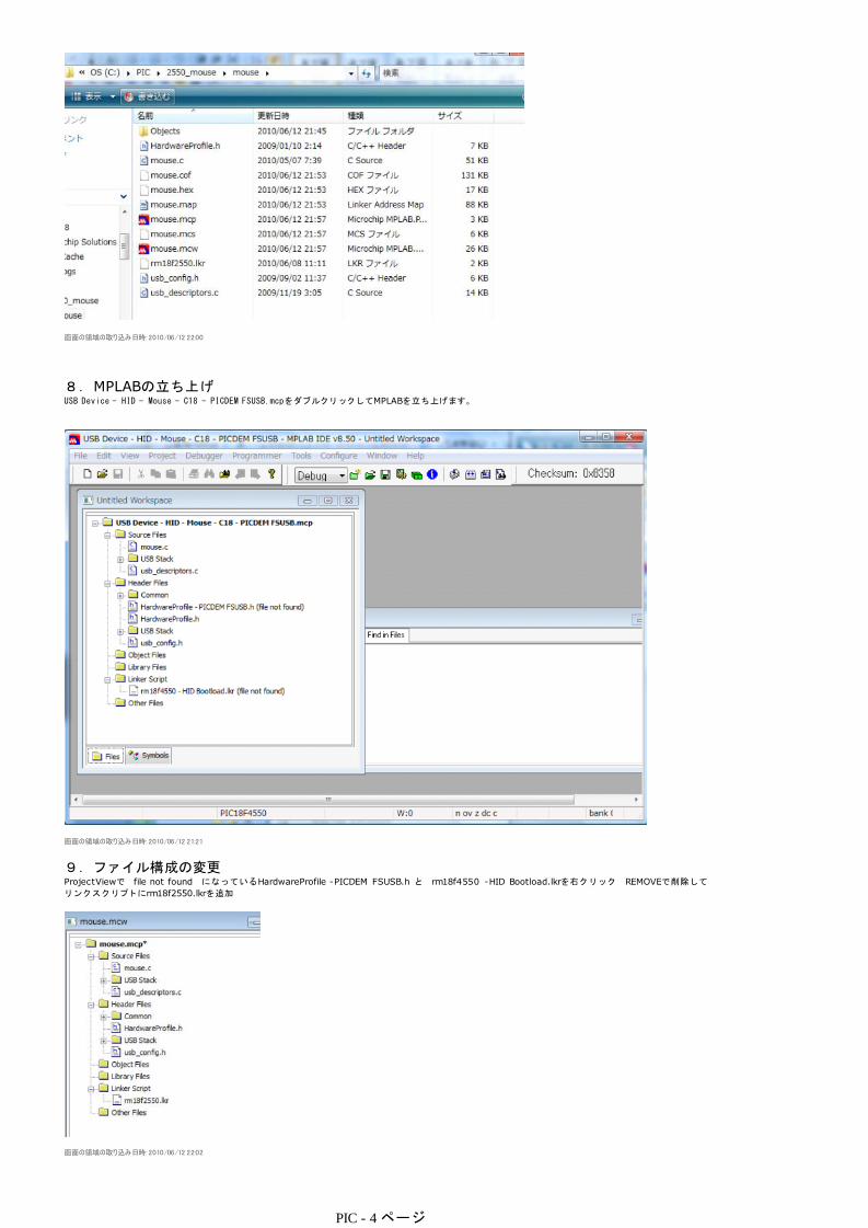
画面の領域の取り込み日時: 2010/06/12 22:00
8.MPLABの立ち上げUSB Device - HID - Mouse - C18 - PICDEM FSUSB.mcpをダブルクリックしてMPLABを立ち上げます。
画面の領域の取り込み日時: 2010/06/12 21:21
9.ファイル構成の変更ProjectViewで file not found になっているHardwareProfile -PICDEM FSUSB.h と rm18f4550 -HID Bootload.lkrを右クリック REMOVEで削除して
リンクスクリプトにrm18f2550.lkrを追加
画面の領域の取り込み日時: 2010/06/12 22:02
PIC - 4 ページ

10.PICの変更メニューバーのConfigure-->Select DeviceでPIC18F2550に変更
画面の領域の取り込み日時: 2010/06/12 21:28
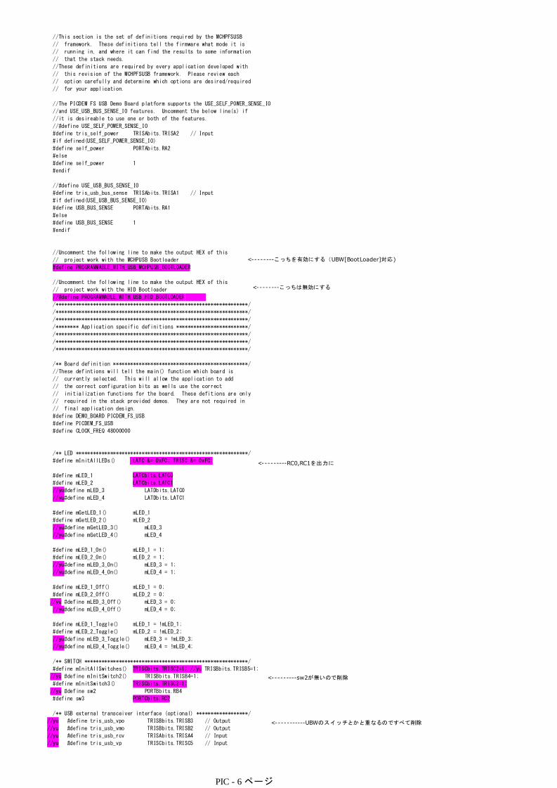
11.ソースの変更HardwareProfile.h内の
#define PROGRAMMABLE_WITH_USB_HID_BOOTLOADER
を
#define PROGRAMMABLE_WITH_USB_MCHPUSB_BOOTLOADER
に変更
BootLoaderのPICはConfigureの設定をしないので、mouse.c内のConfigureの部分は削除
sw3をBootスイッチに割り当て(PORTC2)
Sw2は無いので削除
mLED1、mLED2をLEDに割り当てる(PORTC0,C1)
HardwareProfile.hを書き換え
/********************************************************************
FileName: HardwareProfile - PICDEM FSUSB.h
Dependencies: See INCLUDES section
Processor: PIC18 USB Microcontrollers
Hardware: PICDEM FSUSB
Compiler: Microchip C18
Company: Microchip Technology, Inc.
Software License Agreement:
The software supplied herewith by Microchip Technology Incorporated
(the 鼎ompany・ for its PICョ Microcontroller is intended and
supplied to you, the Company痴 customer, for use solely and
exclusively on Microchip PIC Microcontroller products. The
software is owned by the Company and/or its supplier, and is
protected under applicable copyright laws. All rights are reserved.
Any use in violation of the foregoing restrictions may subject the
user to criminal sanctions under applicable laws, as well as to
civil liability for the breach of the terms and conditions of this
license.
THIS SOFTWARE IS PROVIDED IN AN 鄭S IS・CONDITION. NO WARRANTIES,
WHETHER EXPRESS, IMPLIED OR STATUTORY, INCLUDING, BUT NOT LIMITED
TO, IMPLIED WARRANTIES OF MERCHANTABILITY AND FITNESS FOR A
PARTICULAR PURPOSE APPLY TO THIS SOFTWARE. THE COMPANY SHALL NOT,
IN ANY CIRCUMSTANCES, BE LIABLE FOR SPECIAL, INCIDENTAL OR
CONSEQUENTIAL DAMAGES, FOR ANY REASON WHATSOEVER.
********************************************************************
File Description:
Change History:
Rev Date Description
1.0 11/19/2004 Initial release
2.1 02/26/2007 Updated for simplicity and to use common
coding style
2.3 09/15/2008 Broke out each hardware platform into its own
"HardwareProfile - xxx.h" file
********************************************************************/
#ifndef HARDWARE_PROFILE_PICDEM_FSUSB_H
#define HARDWARE_PROFILE_PICDEM_FSUSB_H
/*******************************************************************/
/******** USB stack hardware selection options *********************/
/*******************************************************************/
PIC - 5 ページ
//This section is the set of definitions required by the MCHPFSUSB
// framework. These definitions tell the firmware what mode it is
// running in, and where it can find the results to some information
// that the stack needs.
//These definitions are required by every application developed with
// this revision of the MCHPFSUSB framework. Please review each
// option carefully and determine which options are desired/required
// for your application.
//The PICDEM FS USB Demo Board platform supports the USE_SELF_POWER_SENSE_IO
//and USE_USB_BUS_SENSE_IO features. Uncomment the below line(s) if
//it is desireable to use one or both of the features.
//#define USE_SELF_POWER_SENSE_IO
#define tris_self_power TRISAbits.TRISA2 // Input
#if defined(USE_SELF_POWER_SENSE_IO)
#define self_power PORTAbits.RA2
#else
#define self_power 1
#endif
//#define USE_USB_BUS_SENSE_IO
#define tris_usb_bus_sense TRISAbits.TRISA1 // Input
#if defined(USE_USB_BUS_SENSE_IO)
#define USB_BUS_SENSE PORTAbits.RA1
#else
#define USB_BUS_SENSE 1
#endif
//Uncomment the following line to make the output HEX of this
// project work with the MCHPUSB Bootloader
#define PROGRAMMABLE_WITH_USB_MCHPUSB_BOOTLOADER
//Uncomment the following line to make the output HEX of this
// project work with the HID Bootloader
//#define PROGRAMMABLE_WITH_USB_HID_BOOTLOADER
/*******************************************************************/
/*******************************************************************/
/*******************************************************************/
/******** Application specific definitions *************************/
/*******************************************************************/
/*******************************************************************/
/*******************************************************************/
/** Board definition ***********************************************/
//These defintions will tell the main() function which board is
// currently selected. This will allow the application to add
// the correct configuration bits as wells use the correct
// initialization functions for the board. These defitions are only
// required in the stack provided demos. They are not required in
// final application design.
#define DEMO_BOARD PICDEM_FS_USB
#define PICDEM_FS_USB
#define CLOCK_FREQ 48000000
/** LED ************************************************************/
#define mInitAllLEDs() LATC &= 0xFC; TRISC &= 0xFC;
#define mLED_1 LATCbits.LATC0
#define mLED_2 LATCbits.LATC1
//yu#define mLED_3 LATDbits.LATC0
//yu#define mLED_4 LATDbits.LATC1
#define mGetLED_1() mLED_1
#define mGetLED_2() mLED_2
//yu#define mGetLED_3() mLED_3
//yu#define mGetLED_4() mLED_4
#define mLED_1_On() mLED_1 = 1;
#define mLED_2_On() mLED_2 = 1;
//yu#define mLED_3_On() mLED_3 = 1;
//yu#define mLED_4_On() mLED_4 = 1;
#define mLED_1_Off() mLED_1 = 0;
#define mLED_2_Off() mLED_2 = 0;
//yu #define mLED_3_Off() mLED_3 = 0;
//yu#define mLED_4_Off() mLED_4 = 0;
#define mLED_1_Toggle() mLED_1 = !mLED_1;
#define mLED_2_Toggle() mLED_2 = !mLED_2;
//yu#define mLED_3_Toggle() mLED_3 = !mLED_3;
//yu#define mLED_4_Toggle() mLED_4 = !mLED_4;
/** SWITCH *********************************************************/
#define mInitAllSwitches() TRISCbits.TRISC2=1; //yu TRISBbits.TRISB5=1;
//yu #define mInitSwitch2() TRISBbits.TRISB4=1;
#define mInitSwitch3() TRISCbits.TRISC2=1;
//yu #define sw2 PORTBbits.RB4
#define sw3 PORTCbits.RC2
/** USB external transceiver interface (optional) ******************/
//yu #define tris_usb_vpo TRISBbits.TRISB3 // Output
//yu #define tris_usb_vmo TRISBbits.TRISB2 // Output
//yu #define tris_usb_rcv TRISAbits.TRISA4 // Input
//yu #define tris_usb_vp TRISCbits.TRISC5 // Input
<--------こっちを有効にする(UBW[BootLoader]対応)
<--------こっちは無効にする
<-----------UBWのスイッチとかと重なるのですべて削除
<---------sw2が無いので削除
<---------RC0,RC1を出力に
PIC - 6 ページ

//yu #define tris_usb_vm TRISCbits.TRISC4 // Input
//yu #define tris_usb_oe TRISCbits.TRISC1 // Output
//yu #define tris_usb_suspnd TRISAbits.TRISA3 // Output
/** I/O pin definitions ********************************************/
#define INPUT_PIN 1
#define OUTPUT_PIN 0
#endif //HARDWARE_PROFILE_PICDEM_FSUSB_H
mouse.cは
/********************************************************************
FileName: mouse.c
Dependencies: See INCLUDES section
Processor: PIC18, PIC24, and PIC32 USB Microcontrollers
Hardware: This demo is natively intended to be used on Microchip USB demo
boards supported by the MCHPFSUSB stack. See release notes for
support matrix. This demo can be modified for use on other hardware
platforms.
Complier: Microchip C18 (for PIC18), C30 (for PIC24), C32 (for PIC32)
Company: Microchip Technology, Inc.
Software License Agreement:
The software supplied herewith by Microchip Technology Incorporated
(the 鼎ompany・ for its PICョ Microcontroller is intended and
supplied to you, the Company痴 customer, for use solely and
exclusively on Microchip PIC Microcontroller products. The
software is owned by the Company and/or its supplier, and is
protected under applicable copyright laws. All rights are reserved.
Any use in violation of the foregoing restrictions may subject the
user to criminal sanctions under applicable laws, as well as to
civil liability for the breach of the terms and conditions of this
license.
THIS SOFTWARE IS PROVIDED IN AN 鄭S IS・CONDITION. NO WARRANTIES,
WHETHER EXPRESS, IMPLIED OR STATUTORY, INCLUDING, BUT NOT LIMITED
TO, IMPLIED WARRANTIES OF MERCHANTABILITY AND FITNESS FOR A
PARTICULAR PURPOSE APPLY TO THIS SOFTWARE. THE COMPANY SHALL NOT,
IN ANY CIRCUMSTANCES, BE LIABLE FOR SPECIAL, INCIDENTAL OR
CONSEQUENTIAL DAMAGES, FOR ANY REASON WHATSOEVER.
********************************************************************
File Description:
Change History:
Rev Description
---- -----------------------------------------
1.0 Initial release
2.1 Updated for simplicity and to use common coding style
2.6a Updated to allow screen savers to come on by only sending
one packet indicating no movement and then allowing the
endpoint to NAK until the next time movement is registered.
2.7 Added example to put PIC24F devices to sleep using USB
activity to wake the device back up.
********************************************************************/
#ifndef USBMOUSE_C
#define USBMOUSE_C
/** INCLUDES *******************************************************/
#include "./USB/usb.h"
#include "HardwareProfile.h"
#include "./USB/usb_function_hid.h"
/** CONFIGURATION **************************************************/
//この間はすべて削除
/** VARIABLES ******************************************************/
#pragma udata
BYTE old_sw2,old_sw3;
BOOL emulate_mode;
BYTE movement_length;
BYTE vector = 0;
char buffer[3];
USB_HANDLE lastTransmission;
//The direction that the mouse will move in
ROM signed char dir_table[]={-4,-4,-4, 0, 4, 4, 4, 0};
/** PRIVATE PROTOTYPES *********************************************/
void BlinkUSBStatus(void);
BOOL Switch2IsPressed(void);
BOOL Switch3IsPressed(void);
void Emulate_Mouse(void);
static void InitializeSystem(void);
void ProcessIO(void);
void UserInit(void);
void YourHighPriorityISRCode();
void YourLowPriorityISRCode();
/** VECTOR REMAPPING ***********************************************/
<-----BootLoaderはConfigurationできません。
PIC - 7 ページ

//On PIC18 devices, addresses 0x00, 0x08, and 0x18 are used for
//the reset, high priority interrupt, and low priority interrupt
//vectors. However, the current Microchip USB bootloader
//examples are intended to occupy addresses 0x00-0x7FF or
//0x00-0xFFF depending on which bootloader is used. Therefore,
//the bootloader code remaps these vectors to new locations
//as indicated below. This remapping is only necessary if you
//wish to program the hex file generated from this project with
//the USB bootloader. If no bootloader is used, edit the
//usb_config.h file and comment out the following defines:
//#define PROGRAMMABLE_WITH_USB_HID_BOOTLOADER
//#define PROGRAMMABLE_WITH_USB_LEGACY_CUSTOM_CLASS_BOOTLOADER
#define REMAPPED_RESET_VECTOR_ADDRESS 0x1000
#define REMAPPED_HIGH_INTERRUPT_VECTOR_ADDRESS 0x1008
#define REMAPPED_LOW_INTERRUPT_VECTOR_ADDRESS 0x1018
#if defined(PROGRAMMABLE_WITH_USB_HID_BOOTLOADER)
#define REMAPPED_RESET_VECTOR_ADDRESS 0x800
#define REMAPPED_HIGH_INTERRUPT_VECTOR_ADDRESS 0x808
#define REMAPPED_LOW_INTERRUPT_VECTOR_ADDRESS 0x818
#elif defined(PROGRAMMABLE_WITH_USB_MCHPUSB_BOOTLOADER)
#define REMAPPED_RESET_VECTOR_ADDRESS 0x00
#define REMAPPED_HIGH_INTERRUPT_VECTOR_ADDRESS 0x08
#define REMAPPED_LOW_INTERRUPT_VECTOR_ADDRESS 0x18
#else
#endif
#if defined(PROGRAMMABLE_WITH_USB_HID_BOOTLOADER)||defined(PROGRAMMABLE_WITH_USB_MCHPUSB_BOOTLOADER)
extern void _startup (void); // See c018i.c in your C18 compiler dir
#pragma code REMAPPED_RESET_VECTOR = REMAPPED_RESET_VECTOR_ADDRESS
void _reset (void)
{
_asm goto _startup _endasm
}
#endif
#pragma code REMAPPED_HIGH_INTERRUPT_VECTOR = REMAPPED_HIGH_INTERRUPT_VECTOR_ADDRESS
void Remapped_High_ISR (void)
{
_asm goto YourHighPriorityISRCode _endasm
}
#pragma code REMAPPED_LOW_INTERRUPT_VECTOR = REMAPPED_LOW_INTERRUPT_VECTOR_ADDRESS
void Remapped_Low_ISR (void)
{
_asm goto YourLowPriorityISRCode _endasm
}
#if defined(PROGRAMMABLE_WITH_USB_HID_BOOTLOADER)||defined(PROGRAMMABLE_WITH_USB_MCHPUSB_BOOTLOADER)
//Note: If this project is built while one of the bootloaders has
//been defined, but then the output hex file is not programmed with
//the bootloader, addresses 0x08 and 0x18 would end up programmed with 0xFFFF.
//As a result, if an actual interrupt was enabled and occured, the PC would jump
//to 0x08 (or 0x18) and would begin executing "0xFFFF" (unprogrammed space). This
//executes as nop instructions, but the PC would eventually reach the REMAPPED_RESET_VECTOR_ADDRESS
//(0x1000 or 0x800, depending upon bootloader), and would execute the "goto _startup". This
//would effective reset the application.
//To fix this situation, we should always deliberately place a
//"goto REMAPPED_HIGH_INTERRUPT_VECTOR_ADDRESS" at address 0x08, and a
//"goto REMAPPED_LOW_INTERRUPT_VECTOR_ADDRESS" at address 0x18. When the output
//hex file of this project is programmed with the bootloader, these sections do not
//get bootloaded (as they overlap the bootloader space). If the output hex file is not
//programmed using the bootloader, then the below goto instructions do get programmed,
//and the hex file still works like normal. The below section is only required to fix this
//scenario.
#pragma code HIGH_INTERRUPT_VECTOR = 0x08
void High_ISR (void)
{
_asm goto REMAPPED_HIGH_INTERRUPT_VECTOR_ADDRESS _endasm
}
#pragma code LOW_INTERRUPT_VECTOR = 0x18
void Low_ISR (void)
{
_asm goto REMAPPED_LOW_INTERRUPT_VECTOR_ADDRESS _endasm
}
#endif //end of "#if defined(PROGRAMMABLE_WITH_USB_HID_BOOTLOADER)||defined(PROGRAMMABLE_WITH_USB_LEGACY_CUSTOM_CLASS_BOOTLOADER)"
#if defined(__18CXX)
#pragma code
//These are your actual interrupt handling routines.
#pragma interrupt YourHighPriorityISRCode
void YourHighPriorityISRCode()
//Check which interrupt flag caused the interrupt.
//Service the interrupt
//Clear the interrupt flag
//Etc.
{
USBDeviceTasks();
#if defined(USB_INTERRUPT)
} //This return will be a "retfie fast", since this is in a #pragma interrupt section
#pragma interruptlow YourLowPriorityISRCode
void YourLowPriorityISRCode()
{
#endif
PIC - 8 ページ

//Check which interrupt flag caused the interrupt.
//Service the interrupt
//Clear the interrupt flag
//Etc.
} //This return will be a "retfie", since this is in a #pragma interruptlow section
#endif
/** DECLARATIONS ***************************************************/
#pragma code
/********************************************************************
* Function: void main(void)
*
* PreCondition: None
*
* Input: None
*
* Output: None
*
* Side Effects: None
*
* Overview: Main program entry point.
*
* Note: None
*******************************************************************/
#if defined(__18CXX)
void main(void)
#else
int main(void)
#endif
{
InitializeSystem();
#if defined(USB_INTERRUPT)
USBDeviceAttach();
#endif
while(1)
{
// Check bus status and service USB interrupts.
#if defined(USB_POLLING)
USBDeviceTasks(); // Interrupt or polling method. If using polling, must call
// this function periodically. This function will take care
// of processing and responding to SETUP transactions
// (such as during the enumeration process when you first
// plug in). USB hosts require that USB devices should accept
// and process SETUP packets in a timely fashion. Therefore,
// when using polling, this function should be called
// frequently (such as once about every 100 microseconds) at any
// time that a SETUP packet might reasonably be expected to
// be sent by the host to your device. In most cases, the
// USBDeviceTasks() function does not take very long to
// execute (~50 instruction cycles) before it returns.
#endif
// Application-specific tasks.
// Application related code may be added here, or in the ProcessIO() function.
ProcessIO();
}//end while
}//end main
/********************************************************************
* Function: static void InitializeSystem(void)
*
* PreCondition: None
*
* Input: None
*
* Output: None
*
* Side Effects: None
*
* Overview: InitializeSystem is a centralize initialization
* routine. All required USB initialization routines
* are called from here.
*
* User application initialization routine should
* also be called from here.
*
* Note: None
*******************************************************************/
static void InitializeSystem(void)
{
#if (defined(__18CXX) & !defined(PIC18F87J50_PIM))
ADCON1 |= 0x0F; // Default all pins to digital
#elif defined(__C30__)
#if defined(__PIC24FJ256GB110__) || defined(__PIC24FJ256GB106__)
AD1PCFGL = 0xFFFF;
#endif
PIC - 9 ページ

#elif defined(__C32__)
AD1PCFG = 0xFFFF;
#endif
//On the PIC18F87J50 Family of USB microcontrollers, the PLL will not power up and be enabled
//by default, even if a PLL enabled oscillator configuration is selected (such as HS+PLL).
//This allows the device to power up at a lower initial operating frequency, which can be
//advantageous when powered from a source which is not gauranteed to be adequate for 48MHz
//operation. On these devices, user firmware needs to manually set the OSCTUNE<PLLEN> bit to
//power up the PLL.
#if defined(PIC18F87J50_PIM) || defined(PIC18F46J50_PIM) || defined(PIC18F_STARTER_KIT_1) || defined(PIC18F47J53_PIM)
{
unsigned int pll_startup_counter = 600;
OSCTUNEbits.PLLEN = 1; //Enable the PLL and wait 2+ms until the PLL locks before enabling USB module
while(pll_startup_counter--);
}
//Device switches over automatically to PLL output after PLL is locked and ready.
#endif
//Configure all I/O pins to use digital input buffers. The PIC18F87J50 Family devices
//use the ANCONx registers to control this, which is different from other devices which
//use the ADCON1 register for this purpose.
#if defined(PIC18F87J50_PIM)
WDTCONbits.ADSHR = 1; // Select alternate SFR location to access ANCONx registers
ANCON0 = 0xFF; // Default all pins to digital
ANCON1 = 0xFF; // Default all pins to digital
WDTCONbits.ADSHR = 0; // Select normal SFR locations
#endif
//Configure all I/O pins to use digital input buffers. The PIC18F87J50 Family devices
//use the ANCONx registers to control this, which is different from other devices which
//use the ADCON1 register for this purpose.
#if defined(PIC18F46J50_PIM) || defined(PIC18F_STARTER_KIT_1) || defined(PIC18F47J53_PIM)
ANCON0 = 0xFF; // Default all pins to digital
ANCON1 = 0xFF; // Default all pins to digital
#endif
//On the PIC24FJ64GB004 Family of USB microcontrollers, the PLL will not power up and be enabled
//by default, even if a PLL enabled oscillator configuration is selected (such as HS+PLL).
//This allows the device to power up at a lower initial operating frequency, which can be
//advantageous when powered from a source which is not gauranteed to be adequate for 32MHz
//operation. On these devices, user firmware needs to manually set the CLKDIV<PLLEN> bit to
//power up the PLL.
#if defined(PIC24FJ64GB004_PIM) || defined(PIC24FJ256DA210_DEV_BOARD)
{
unsigned int pll_startup_counter = 600;
CLKDIVbits.PLLEN = 1;
while(pll_startup_counter--);
}
//Device switches over automatically to PLL output after PLL is locked and ready.
#endif
// The USB specifications require that USB peripheral devices must never source
// current onto the Vbus pin. Additionally, USB peripherals should not source
// current on D+ or D- when the host/hub is not actively powering the Vbus line.
// When designing a self powered (as opposed to bus powered) USB peripheral
// device, the firmware should make sure not to turn on the USB module and D+
// or D- pull up resistor unless Vbus is actively powered. Therefore, the
// firmware needs some means to detect when Vbus is being powered by the host.
// A 5V tolerant I/O pin can be connected to Vbus (through a resistor), and
// can be used to detect when Vbus is high (host actively powering), or low
// (host is shut down or otherwise not supplying power). The USB firmware
// can then periodically poll this I/O pin to know when it is okay to turn on
// the USB module/D+/D- pull up resistor. When designing a purely bus powered
// peripheral device, it is not possible to source current on D+ or D- when the
// host is not actively providing power on Vbus. Therefore, implementing this
// bus sense feature is optional. This firmware can be made to use this bus
// sense feature by making sure "USE_USB_BUS_SENSE_IO" has been defined in the
// HardwareProfile.h file.
#if defined(USE_USB_BUS_SENSE_IO)
tris_usb_bus_sense = INPUT_PIN; // See HardwareProfile.h
#endif
// If the host PC sends a GetStatus (device) request, the firmware must respond
// and let the host know if the USB peripheral device is currently bus powered
// or self powered. See chapter 9 in the official USB specifications for details
// regarding this request. If the peripheral device is capable of being both
// self and bus powered, it should not return a hard coded value for this request.
// Instead, firmware should check if it is currently self or bus powered, and
// respond accordingly. If the hardware has been configured like demonstrated
// on the PICDEM FS USB Demo Board, an I/O pin can be polled to determine the
// currently selected power source. On the PICDEM FS USB Demo Board, "RA2"
// is used for this purpose. If using this feature, make sure "USE_SELF_POWER_SENSE_IO"
// has been defined in HardwareProfile.h, and that an appropriate I/O pin has been mapped
// to it in HardwareProfile.h.
#if defined(USE_SELF_POWER_SENSE_IO)
tris_self_power = INPUT_PIN; // See HardwareProfile.h
#endif
UserInit();
USBDeviceInit(); //usb_device.c. Initializes USB module SFRs and firmware
//variables to known states.
}//end InitializeSystem
PIC - 10 ページ

/******************************************************************************
* Function: void UserInit(void)
*
* PreCondition: None
*
* Input: None
*
* Output: None
*
* Side Effects: None
*
* Overview: This routine should take care of all of the demo code
* initialization that is required.
*
* Note:
*
*****************************************************************************/
void UserInit(void)
{
//Initialize all of the LED pins
mInitAllLEDs();
//Initialize all of the push buttons
mInitAllSwitches();
//yu old_sw2 = sw2;
old_sw3 = sw3;
//Initialize all of the mouse data to 0,0,0 (no movement)
buffer[0]=buffer[1]=buffer[2]=0;
//enable emulation mode. This means that the mouse data
//will be send to the PC causing the mouse to move. If this is
//set to FALSE then the demo board will send 0,0,0 resulting
//in no mouse movement
emulate_mode = TRUE;
//initialize the variable holding the handle for the last
// transmission
lastTransmission = 0;
}//end UserInit
/********************************************************************
* Function: void ProcessIO(void)
*
* PreCondition: None
*
* Input: None
*
* Output: None
*
* Side Effects: None
*
* Overview: This function is a place holder for other user
* routines. It is a mixture of both USB and
* non-USB tasks.
*
* Note: None
*******************************************************************/
void ProcessIO(void)
{
//Blink the LEDs according to the USB device status
BlinkUSBStatus();
// User Application USB tasks
if((USBDeviceState < CONFIGURED_STATE)||(USBSuspendControl==1)) return;
if(Switch3IsPressed()) //Note: Switch3IsPressed() implements only the
//some pusbbuttons will behave temperamentally.
//Proper debounce code should be used which
//implements delays millseconds long, and
//checks/reckecks pushbutton state many times to
//verify that the state is stable. In order
//to avoid using blocking functions, or
//microcontroller timer resources this feature
//is not implemented in this example.
{ //crudest of switch debounce code. As a result
emulate_mode = !emulate_mode;
}
//Call the function that emulates the mouse
Emulate_Mouse();
}//end ProcessIO
/******************************************************************************
* Function: void Emulate_Mouse(void)
*
* PreCondition: None
*
* Input: None
*
<----Sw2が無いので削除
PIC - 11 ページ

* Output: None
*
* Side Effects: The ownership of the USB buffers will change according
* to the required operation
*
* Overview: This routine will emulate the function of the mouse. It
* does this by sending IN packets of data to the host.
*
* The generic function HIDTxPacket() is used to send HID
* IN packets over USB to the host.
*
* Note:
*
*****************************************************************************/
void Emulate_Mouse(void)
{
static BOOL sent_dont_move = FALSE;
if(emulate_mode == TRUE)
{
sent_dont_move = FALSE;
//go 14 times in the same direction before changing direction
if(movement_length > 14)
{
buffer[0] = 0;
buffer[1] = dir_table[vector & 0x07]; // X-Vector
buffer[2] = dir_table[(vector+2) & 0x07]; // Y-Vector
//go to the next direction in the table
vector++;
//reset the counter for when to change again
movement_length = 0;
}//end if(movement_length > 14)
}
else
{
//don't move the mouse
buffer[0] = buffer[1] = buffer[2] = 0;
}
if(HIDTxHandleBusy(lastTransmission) == 0)
{
//copy over the data to the HID buffer
hid_report_in[0] = buffer[0];
hid_report_in[1] = buffer[1];
hid_report_in[2] = buffer[2];
if(((sent_dont_move == FALSE) && (emulate_mode == FALSE)) || (emulate_mode == TRUE))
{
//Send the 3 byte packet over USB to the host.
lastTransmission = HIDTxPacket(HID_EP, (BYTE*)hid_report_in, 0x03);
//increment the counter of when to change the data sent
movement_length++;
sent_dont_move = TRUE;
}
}
}//end Emulate_Mouse
/******************************************************************************
* Function: BOOL Switch2IsPressed(void)
*
* PreCondition: None
*
* Input: None
*
* Output: TRUE - pressed, FALSE - not pressed
*
* Side Effects: None
*
* Overview: Indicates if the switch is pressed.
*
* Note:
*
*****************************************************************************/
/** del yu
BOOL Switch2IsPressed(void)
{
if(sw2 != old_sw2)
{
old_sw2 = sw2; // Save new value
if(sw2 == 0) // If pressed
return TRUE; // Was pressed
}//end if
return FALSE; // Was not pressed
}//end Switch2IsPressed
**/
/******************************************************************************
* Function: BOOL Switch3IsPressed(void)
*
* PreCondition: None
*
<-----Sw2がないのでこの関数を削除
PIC - 12 ページ

* Input: None
*
* Output: TRUE - pressed, FALSE - not pressed
*
* Side Effects: None
*
* Overview: Indicates if the switch is pressed.
*
* Note:
*
*****************************************************************************/
BOOL Switch3IsPressed(void)
{
if(sw3 != old_sw3)
{
old_sw3 = sw3; // Save new value
if(sw3 == 0) // If pressed
return TRUE; // Was pressed
}//end if
return FALSE; // Was not pressed
}//end Switch3IsPressed
/********************************************************************
* Function: void BlinkUSBStatus(void)
*
* PreCondition: None
*
* Input: None
*
* Output: None
*
* Side Effects: None
*
* Overview: BlinkUSBStatus turns on and off LEDs
* corresponding to the USB device state.
*
* Note: mLED macros can be found in HardwareProfile.h
* USBDeviceState is declared and updated in
* usb_device.c.
*******************************************************************/
void BlinkUSBStatus(void)
{
static WORD led_count=0;
if(led_count == 0)led_count = 10000U;
led_count--;
#define mLED_Both_Off() {mLED_1_Off();mLED_2_Off();}
#define mLED_Both_On() {mLED_1_On();mLED_2_On();}
#define mLED_Only_1_On() {mLED_1_On();mLED_2_Off();}
#define mLED_Only_2_On() {mLED_1_Off();mLED_2_On();}
if(USBSuspendControl == 1)
{
if(led_count==0)
{
mLED_1_Toggle();
if(mGetLED_1())
{
mLED_2_On();
}
else
{
mLED_2_Off();
}
}//end if
}
else
{
if(USBDeviceState == DETACHED_STATE)
{
mLED_Both_Off();
}
else if(USBDeviceState == ATTACHED_STATE)
{
mLED_Both_On();
}
else if(USBDeviceState == POWERED_STATE)
{
mLED_Only_1_On();
}
else if(USBDeviceState == DEFAULT_STATE)
{
mLED_Only_2_On();
}
else if(USBDeviceState == ADDRESS_STATE)
{
if(led_count == 0)
{
mLED_1_Toggle();
mLED_2_Off();
}//end if
}
else if(USBDeviceState == CONFIGURED_STATE)
{
if(led_count==0)
PIC - 13 ページ

{
mLED_1_Toggle();
if(mGetLED_1())
{
mLED_2_Off();
}
else
{
mLED_2_On();
}
}//end if
}
}
// // No need to clear UIRbits.SOFIF to 0 here.
// // Callback caller is already doing that.
// #define BLINK_INTERVAL 20000
// #define BLANK_INTERVAL 200000
//
// static WORD blink_count=0;
// static DWORD loop_count = 0;
//
// if(loop_count == 0)
// {
// if(blink_count != 0)
// {
// loop_count = BLINK_INTERVAL;
// if(mGetLED_1())
// {
// mLED_1_Off();
// blink_count--;
// }
// else
// {
// mLED_1_On();
// }
// }
// else
// {
// loop_count = BLANK_INTERVAL;
// switch(USBDeviceState)
// {
// case ATTACHED_STATE:
// blink_count = 1;
// break;
// case POWERED_STATE:
// blink_count = 2;
// break;
// case DEFAULT_STATE:
// blink_count = 3;
// break;
// case ADR_PENDING_STATE:
// blink_count = 4;
// break;
// case ADDRESS_STATE:
// blink_count = 5;
// break;
// case CONFIGURED_STATE:
// blink_count = 6;
// break;
// case DETACHED_STATE:
// //fall through
// default:
// blink_count = 0;
// break;
// }
// }
// }
// else
// {
// loop_count--;
// }
}//end BlinkUSBStatus
// ******************************************************************************************************
// ************** USB Callback Functions ****************************************************************
// ******************************************************************************************************
// The USB firmware stack will call the callback functions USBCBxxx() in response to certain USB related
// events. For example, if the host PC is powering down, it will stop sending out Start of Frame (SOF)
// packets to your device. In response to this, all USB devices are supposed to decrease their power
// consumption from the USB Vbus to <2.5mA each. The USB module detects this condition (which according
// to the USB specifications is 3+ms of no bus activity/SOF packets) and then calls the USBCBSuspend()
// function. You should modify these callback functions to take appropriate actions for each of these
// conditions. For example, in the USBCBSuspend(), you may wish to add code that will decrease power
// consumption from Vbus to <2.5mA (such as by clock switching, turning off LEDs, putting the
// microcontroller to sleep, etc.). Then, in the USBCBWakeFromSuspend() function, you may then wish to
// add code that undoes the power saving things done in the USBCBSuspend() function.
// The USBCBSendResume() function is special, in that the USB stack will not automatically call this
// function. This function is meant to be called from the application firmware instead. See the
// additional comments near the function.
/******************************************************************************
PIC - 14 ページ
* Function: void USBCBSuspend(void)
*
* PreCondition: None
*
* Input: None
*
* Output: None
*
* Side Effects: None
*
* Overview: Call back that is invoked when a USB suspend is detected
*
* Note: None
*****************************************************************************/
void USBCBSuspend(void)
//Example power saving code. Insert appropriate code here for the desired
//application behavior. If the microcontroller will be put to sleep, a
//process similar to that shown below may be used:
//ConfigureIOPinsForLowPower();
//SaveStateOfAllInterruptEnableBits();
//DisableAllInterruptEnableBits();
//EnableOnlyTheInterruptsWhichWillBeUsedToWakeTheMicro(); //should enable at least USBActivityIF as a wake source
//Sleep();
//RestoreStateOfAllPreviouslySavedInterruptEnableBits(); //Preferrably, this should be done in the USBCBWakeFromSuspend() function instead.
//RestoreIOPinsToNormal(); //Preferrably, this should be done in the
USBCBWakeFromSuspend() function instead.
{
//IMPORTANT NOTE: Do not clear the USBActivityIF (ACTVIF) bit here. This bit is
//cleared inside the usb_device.c file. Clearing USBActivityIF here will cause
//things to not work as intended.
#if defined(__C30__)
_IPL = 7;
USBSleepOnSuspend();
_IPL = 0;
#endif
}
/******************************************************************************
* Function: void USBCBWakeFromSuspend(void)
*
* PreCondition: None
*
* Input: None
*
* Output: None
*
* Side Effects: None
*
* Overview: The host may put USB peripheral devices in low power
* suspend mode (by "sending" 3+ms of idle). Once in suspend
* mode, the host may wake the device back up by sending non-
* idle state signalling.
*
* This call back is invoked when a wakeup from USB suspend
* is detected.
*
* Note: None
*****************************************************************************/
void USBCBWakeFromSuspend(void)
// If clock switching or other power savings measures were taken when
// executing the USBCBSuspend() function, now would be a good time to
// switch back to normal full power run mode conditions. The host allows
// a few milliseconds of wakeup time, after which the device must be
// fully back to normal, and capable of receiving and processing USB
// packets. In order to do this, the USB module must receive proper
// clocking (IE: 48MHz clock must be available to SIE for full speed USB
// operation).
{
}
/********************************************************************
* Function: void USBCB_SOF_Handler(void)
*
* PreCondition: None
*
* Input: None
*
* Output: None
*
* Side Effects: None
*
* Overview: The USB host sends out a SOF packet to full-speed
* devices every 1 ms. This interrupt may be useful
* for isochronous pipes. End designers should
* implement callback routine as necessary.
*
* Note: None
*******************************************************************/
void USBCB_SOF_Handler(void)
{
// No need to clear UIRbits.SOFIF to 0 here.
// Callback caller is already doing that.
PIC - 15 ページ
}
/*******************************************************************
* Function: void USBCBErrorHandler(void)
*
* PreCondition: None
*
* Input: None
*
* Output: None
*
* Side Effects: None
*
* Overview: The purpose of this callback is mainly for
* debugging during development. Check UEIR to see
* which error causes the interrupt.
*
* Note: None
*******************************************************************/
void USBCBErrorHandler(void)
{
// No need to clear UEIR to 0 here.
// Callback caller is already doing that.
// Typically, user firmware does not need to do anything special
// if a USB error occurs. For example, if the host sends an OUT
// packet to your device, but the packet gets corrupted (ex:
// because of a bad connection, or the user unplugs the
// USB cable during the transmission) this will typically set
// one or more USB error interrupt flags. Nothing specific
// needs to be done however, since the SIE will automatically
// send a "NAK" packet to the host. In response to this, the
// host will normally retry to send the packet again, and no
// data loss occurs. The system will typically recover
// automatically, without the need for application firmware
// intervention.
// Nevertheless, this callback function is provided, such as
// for debugging purposes.
}
/*******************************************************************
* Function: void USBCBCheckOtherReq(void)
*
* PreCondition: None
*
* Input: None
*
* Output: None
*
* Side Effects: None
*
* Overview: When SETUP packets arrive from the host, some
* firmware must process the request and respond
* appropriately to fulfill the request. Some of
* the SETUP packets will be for standard
* USB "chapter 9" (as in, fulfilling chapter 9 of
* the official USB specifications) requests, while
* others may be specific to the USB device class
* that is being implemented. For example, a HID
* class device needs to be able to respond to
* "GET REPORT" type of requests. This
* is not a standard USB chapter 9 request, and
* therefore not handled by usb_device.c. Instead
* this request should be handled by class specific
* firmware, such as that contained in usb_function_hid.c.
*
* Note: None
*******************************************************************/
void USBCBCheckOtherReq(void)
{
USBCheckHIDRequest();
}//end
/*******************************************************************
* Function: void USBCBStdSetDscHandler(void)
*
* PreCondition: None
*
* Input: None
*
* Output: None
*
* Side Effects: None
*
* Overview: The USBCBStdSetDscHandler() callback function is
* called when a SETUP, bRequest: SET_DESCRIPTOR request
* arrives. Typically SET_DESCRIPTOR requests are
* not used in most applications, and it is
* optional to support this type of request.
*
* Note: None
*******************************************************************/
void USBCBStdSetDscHandler(void)
PIC - 16 ページ

{
// Must claim session ownership if supporting this request
}//end
/*******************************************************************
* Function: void USBCBInitEP(void)
*
* PreCondition: None
*
* Input: None
*
* Output: None
*
* Side Effects: None
*
* Overview: This function is called when the device becomes
* initialized, which occurs after the host sends a
* SET_CONFIGURATION (wValue not = 0) request. This
* callback function should initialize the endpoints
* for the device's usage according to the current
* configuration.
*
* Note: None
*******************************************************************/
void USBCBInitEP(void)
{
//enable the HID endpoint
USBEnableEndpoint(HID_EP,USB_IN_ENABLED|USB_HANDSHAKE_ENABLED|USB_DISALLOW_SETUP);
}
/********************************************************************
* Function: void USBCBSendResume(void)
*
* PreCondition: None
*
* Input: None
*
* Output: None
*
* Side Effects: None
*
* Overview: The USB specifications allow some types of USB
* peripheral devices to wake up a host PC (such
* as if it is in a low power suspend to RAM state).
* This can be a very useful feature in some
* USB applications, such as an Infrared remote
* controlreceiver. If a user presses the "power"
* button on a remote control, it is nice that the
* IR receiver can detect this signalling, and then
* send a USB "command" to the PC to wake up.
*
* The USBCBSendResume() "callback" function is used
* to send this special USB signalling which wakes
* up the PC. This function may be called by
* application firmware to wake up the PC. This
* function should only be called when:
*
* 1. The USB driver used on the host PC supports
* the remote wakeup capability.
* 2. The USB configuration descriptor indicates
* the device is remote wakeup capable in the
* bmAttributes field.
* 3. The USB host PC is currently sleeping,
* and has previously sent your device a SET
* FEATURE setup packet which "armed" the
* remote wakeup capability.
*
* This callback should send a RESUME signal that
* has the period of 1-15ms.
*
* Note: Interrupt vs. Polling
* -Primary clock
* -Secondary clock ***** MAKE NOTES ABOUT THIS *******
* > Can switch to primary first by calling USBCBWakeFromSuspend()
* The modifiable section in this routine should be changed
* to meet the application needs. Current implementation
* temporary blocks other functions from executing for a
* period of 1-13 ms depending on the core frequency.
*
* According to USB 2.0 specification section 7.1.7.7,
* "The remote wakeup device must hold the resume signaling
* for at lest 1 ms but for no more than 15 ms."
* The idea here is to use a delay counter loop, using a
* common value that would work over a wide range of core
* frequencies.
* That value selected is 1800. See table below:
* ==========================================================
* Core Freq(MHz) MIP RESUME Signal Period (ms)
* ==========================================================
* 48 12 1.05
* 4 1 12.6
* ==========================================================
* * These timing could be incorrect when using code
* optimization or extended instruction mode,
* or when having other interrupts enabled.
PIC - 17 ページ

* or when having other interrupts enabled.
* Make sure to verify using the MPLAB SIM's Stopwatch
* and verify the actual signal on an oscilloscope.
*******************************************************************/
void USBCBSendResume(void)
{
static WORD delay_count;
USBResumeControl = 1; // Start RESUME signaling
delay_count = 1800U; // Set RESUME line for 1-13 ms
do
{
delay_count--;
}while(delay_count);
USBResumeControl = 0;
}
/*******************************************************************
* Function: BOOL USER_USB_CALLBACK_EVENT_HANDLER(
* USB_EVENT event, void *pdata, WORD size)
*
* PreCondition: None
*
* Input: USB_EVENT event - the type of event
* void *pdata - pointer to the event data
* WORD size - size of the event data
*
* Output: None
*
* Side Effects: None
*
* Overview: This function is called from the USB stack to
* notify a user application that a USB event
* occured. This callback is in interrupt context
* when the USB_INTERRUPT option is selected.
*
* Note: None
*******************************************************************/
BOOL USER_USB_CALLBACK_EVENT_HANDLER(USB_EVENT event, void *pdata, WORD size)
{
switch(event)
{
case EVENT_CONFIGURED:
USBCBInitEP();
break;
case EVENT_SET_DESCRIPTOR:
USBCBStdSetDscHandler();
break;
case EVENT_EP0_REQUEST:
USBCBCheckOtherReq();
break;
case EVENT_SOF:
USBCB_SOF_Handler();
break;
case EVENT_SUSPEND:
USBCBSuspend();
break;
case EVENT_RESUME:
USBCBWakeFromSuspend();
break;
case EVENT_BUS_ERROR:
USBCBErrorHandler();
break;
case EVENT_TRANSFER:
Nop();
break;
default:
break;
}
return TRUE;
}
/** EOF mouse.c *************************************************/
#endif
*****ではプログラムの内容を理解してみましょう*******
PIC - 18 ページ

画面の領域の取り込み日時: 2010/06/13 11:20
USB Stack内 および Common内は使う分には理解しなくてよいので、理解すべきファイルは
mouse.c,usb_descriptors.c,HardwareProfile.h,usb_config.h,rm18f2550.lkrの5個で良い。
まず、usb_config.hから
/********************************************************************
FileName: usb_config.h
Dependencies: Always: GenericTypeDefs.h, usb_device.h
Situational: usb_function_hid.h, usb_function_cdc.h, usb_function_msd.h, etc.
Processor: PIC18 or PIC24 USB Microcontrollers
Hardware: The code is natively intended to be used on the following
hardware platforms: PICDEM・FS USB Demo Board,
PIC18F87J50 FS USB Plug-In Module, or
Explorer 16 + PIC24 USB PIM. The firmware may be
modified for use on other USB platforms by editing the
HardwareProfile.h file.
Complier: Microchip C18 (for PIC18) or C30 (for PIC24)
Company: Microchip Technology, Inc.
Software License Agreement:
The software supplied herewith by Microchip Technology Incorporated
(the 鼎ompany・ for its PICョ Microcontroller is intended and
supplied to you, the Company痴 customer, for use solely and
exclusively on Microchip PIC Microcontroller products. The
software is owned by the Company and/or its supplier, and is
protected under applicable copyright laws. All rights are reserved.
Any use in violation of the foregoing restrictions may subject the
user to criminal sanctions under applicable laws, as well as to
civil liability for the breach of the terms and conditions of this
license.
THIS SOFTWARE IS PROVIDED IN AN 鄭S IS・CONDITION. NO WARRANTIES,
WHETHER EXPRESS, IMPLIED OR STATUTORY, INCLUDING, BUT NOT LIMITED
TO, IMPLIED WARRANTIES OF MERCHANTABILITY AND FITNESS FOR A
PARTICULAR PURPOSE APPLY TO THIS SOFTWARE. THE COMPANY SHALL NOT,
IN ANY CIRCUMSTANCES, BE LIABLE FOR SPECIAL, INCIDENTAL OR
CONSEQUENTIAL DAMAGES, FOR ANY REASON WHATSOEVER.
********************************************************************
File Description:
Change History:
Rev Date Description
1.0 11/19/2004 Initial release
2.1 02/26/2007 Updated for simplicity and to use common
coding style
*******************************************************************/
/*********************************************************************
* Descriptor specific type definitions are defined in: usbd.h
********************************************************************/
#ifndef USBCFG_H
#define USBCFG_H
/** DEFINITIONS ****************************************************/
// Using larger options take more SRAM, but
// does not provide much advantage in most types
// of applications. Exceptions to this, are applications
// that use EP0 IN or OUT for sending large amounts of
// application related data.
#define USB_EP0_BUFF_SIZE 8 // Valid Options: 8, 16, 32, or 64 bytes.
#define USB_MAX_NUM_INT 1 // For tracking Alternate Setting
#define USB_MAX_EP_NUMBER 1
//Device descriptor - if these two definitions are not defined then
// a ROM USB_DEVICE_DESCRIPTOR variable by the exact name of device_dsc
// must exist.
#define USB_USER_DEVICE_DESCRIPTOR &device_dsc
#define USB_USER_DEVICE_DESCRIPTOR_INCLUDE extern ROM USB_DEVICE_DESCRIPTOR device_dsc
//Configuration descriptors - if these two definitions do not exist then
PIC - 19 ページ

//Configuration descriptors - if these two definitions do not exist then
// a ROM BYTE *ROM variable named exactly USB_CD_Ptr[] must exist.
//#define USB_USER_CONFIG_DESCRIPTOR USB_CD_Ptr
//#define USB_USER_CONFIG_DESCRIPTOR_INCLUDE extern ROM BYTE *ROM USB_CD_Ptr[]
//Make sure only one of the below "#define USB_PING_PONG_MODE"
//is uncommented.
//#define USB_PING_PONG_MODE USB_PING_PONG__NO_PING_PONG
#define USB_PING_PONG_MODE USB_PING_PONG__FULL_PING_PONG
//#define USB_PING_PONG_MODE USB_PING_PONG__EP0_OUT_ONLY
//#define USB_PING_PONG_MODE USB_PING_PONG__ALL_BUT_EP0 //NOTE: This mode is not supported in PIC18F4550 family rev A3 devices
#define USB_POLLING
//#define USB_INTERRUPT
/* Parameter definitions are defined in usb_device.h */
#define USB_PULLUP_OPTION USB_PULLUP_ENABLE
//#define USB_PULLUP_OPTION USB_PULLUP_DISABLED
#define USB_TRANSCEIVER_OPTION USB_INTERNAL_TRANSCEIVER
//External Transceiver support is not available on all product families. Please
// refer to the product family datasheet for more information if this feature
// is available on the target processor.
//#define USB_TRANSCEIVER_OPTION USB_EXTERNAL_TRANSCEIVER
#define USB_SPEED_OPTION USB_FULL_SPEED
//#define USB_SPEED_OPTION USB_LOW_SPEED //(not valid option for PIC24F devices)
#define MY_VID 0x04D8
#define MY_PID 0x0000
#define USB_SUPPORT_DEVICE
#define USB_NUM_STRING_DESCRIPTORS 3
//#define USB_INTERRUPT_LEGACY_CALLBACKS
#define USB_ENABLE_ALL_HANDLERS
//#define USB_ENABLE_SUSPEND_HANDLER
//#define USB_ENABLE_WAKEUP_FROM_SUSPEND_HANDLER
//#define USB_ENABLE_SOF_HANDLER
//#define USB_ENABLE_ERROR_HANDLER
//#define USB_ENABLE_OTHER_REQUEST_HANDLER
//#define USB_ENABLE_SET_DESCRIPTOR_HANDLER
//#define USB_ENABLE_INIT_EP_HANDLER
//#define USB_ENABLE_EP0_DATA_HANDLER
//#define USB_ENABLE_TRANSFER_COMPLETE_HANDLER
/** DEVICE CLASS USAGE *********************************************/
#define USB_USE_HID
/** ENDPOINTS ALLOCATION *******************************************/
/* HID */
#define HID_INTF_ID 0x00
#define HID_EP 1
#define HID_INT_OUT_EP_SIZE 3
#define HID_INT_IN_EP_SIZE 3
#define HID_NUM_OF_DSC 1
#define HID_RPT01_SIZE 50
/** DEFINITIONS ****************************************************/
#endif //USBCFG_H
次にusb_descriptors.c
/********************************************************************
FileName: usb_descriptors.c
Dependencies: See INCLUDES section
Processor: PIC18 or PIC24 USB Microcontrollers
Hardware: The code is natively intended to be used on the following
hardware platforms: PICDEM・FS USB Demo Board,
PIC18F87J50 FS USB Plug-In Module, or
Explorer 16 + PIC24 USB PIM. The firmware may be
modified for use on other USB platforms by editing the
HardwareProfile.h file.
Complier: Microchip C18 (for PIC18) or C30 (for PIC24)
Company: Microchip Technology, Inc.
Software License Agreement:
The software supplied herewith by Microchip Technology Incorporated (the 鼎ompany・ for its PICョ Microcontroller is intended and supplied to you, the
Company痴 customer, for use solely and exclusively on Microchip PIC Microcontroller products. The software is owned by the Company and/or its supplier, and
is protected under applicable copyright laws. All rights are reserved. Any use in violation of the foregoing restrictions may subject the user to criminal
sanctions under applicable laws, as well as to civil liability for the breach of the terms and conditions of this license.
THIS SOFTWARE IS PROVIDED IN AN 鄭S IS・CONDITION. NO WARRANTIES, WHETHER EXPRESS, IMPLIED OR STATUTORY, INCLUDING, BUT NOT LIMITED TO, IMPLIED WARRANTIES
OF MERCHANTABILITY AND FITNESS FOR A PARTICULAR PURPOSE APPLY TO THIS SOFTWARE. THE COMPANY SHALL NOT, IN ANY CIRCUMSTANCES, BE LIABLE FOR SPECIAL,
NCIDENTAL OR CONSEQUENTIAL DAMAGES, FOR ANY REASON WHATSOEVER.
*********************************************************************
-usb_descriptors.c-
-------------------------------------------------------------------
Filling in the descriptor values in the usb_descriptors.c file:
-------------------------------------------------------------------
PIC - 20 ページ

[Device Descriptors]
The device descriptor is defined as a USB_DEVICE_DESCRIPTOR type.
This type is defined in usb_ch9.h Each entry into this structure needs to be the correct length for the data type of the entry.
[Configuration Descriptors]
The configuration descriptor was changed in v2.x from a structure to a BYTE array. Given that the configuration is now a byte array each byte of multi-
byte fields must be listed individually. This means that for fields like the total size of the configuration where the field is a 16-bit value "64,0," is
the correct entry for a configuration that is only 64 bytes long and not "64," which is onetoo few bytes.
The configuration attribute must always have the _DEFAULT definition at the minimum. Additional options can be Or ed to the _DEFAULT attribute. Available
options are _SELF and _RWU. These definitions are defined in the usb_device.h file. The _SELF tells the USB host that this device is self-powered. The _RWU
tells the USB host that this device supports Remote Wakeup.
[Endpoint Descriptors]
Like the configuration descriptor, the endpoint descriptors were changed in v2.x of the stack from a structure to a BYTE array. As endpoint descriptors
also has a field that are multi-byte entities, please be sure to specify both bytes of the field. For example, for the endpoint size an endpoint that is
64 bytes needs to have the size defined as "64,0," instead of "64,"
Take the following example:
// Endpoint Descriptor //
0x07, //the size of this descriptor //
USB_DESCRIPTOR_ENDPOINT, //Endpoint Descriptor
_EP02_IN, //EndpointAddress
_INT, //Attributes
0x08,0x00, //size (note: 2 bytes)
0x02, //Interval
The first two parameters are self-explanatory. They specify the length of this endpoint descriptor (7) and the descriptor type. The next parameter
identifies the endpoint, the definitions are defined in usb_device.h and has the following naming
convention:
_EP<##>_<dir>
where ## is the endpoint number and dir is the direction of transfer. The dir has the value of either 'OUT' or 'IN'.
The next parameter identifies the type of the endpoint. Available options are _BULK, _INT, _ISO, and _CTRL. The _CTRL is not typically used because the
default control transfer endpoint is not defined in the USB descriptors. When _ISO option is used, addition options can be ORed to _ISO. Example:
_ISO|_AD|_FE
This describes the endpoint as an isochronous pipe with adaptive and feedback attributes. See usb_device.h and the USB specification for details. The next
parameter defines the size of the endpoint. The last parameter in the polling interval.
-------------------------------------------------------------------
Adding a USB String
-------------------------------------------------------------------
A string descriptor array should have the following format:
rom struct{byte bLength;byte bDscType;word string[size];}sdxxx={sizeof(sdxxx),DSC_STR,<text>};
The above structure provides a means for the C compiler to calculate the length of string descriptor sdxxx, where xxx is theindex number. The first two
bytes of the descriptor are descriptor length and type. The rest <text> are string texts which must be in the unicode format. The unicode format is
achieved by declaring each character as a word type. The whole text string is declared as a word array with the number of characters equals to <size>.
<size> has to be manually counted and entered into the array declaration. Let's study this through an example:
if the string is "USB" , then the string descriptor should be:
(Using index 02)
rom struct{byte bLength;byte bDscType;word string[3];}sd002={ sizeof(sd002),DSC_STR,'U','S','B'};
A USB project may have multiple strings and the firmware supports the management of multiple strings through a look-up table. The look-up table is defined
as:
rom const unsigned char *rom USB_SD_Ptr[]={&sd000,&sd001,&sd002};
The above declaration has 3 strings, sd000, sd001, and sd002. Strings can be removed or added. sd000 is a specialized stringdescriptor. It defines the
language code, usually this is US English (0x0409). The index of the string must match the index position of the USB_SD_Ptr array, &sd000 must be in
position USB_SD_Ptr[0], &sd001 must be in position USB_SD_Ptr[1] and so on.
The look-up table USB_SD_Ptr is used by the get string handler function.
-------------------------------------------------------------------
The look-up table scheme also applies to the configuration descriptor. A USB device may have multiple configuration descriptors, i.e. CFG01, CFG02, etc. To
add a configuration descriptor, user must implement a structure similar to CFG01. The next step is to add the configuration descriptor name, i.e. cfg01,
cfg02,.., to the look-up table USB_CD_Ptr. USB_CD_Ptr[0]is a dummy place holder since configuration 0 is the un-configured state according to the
definition in the USB specification.
********************************************************************/
/*********************************************************************
* Descriptor specific type definitions are defined in:
* usb_device.h
*
* Configuration options are defined in:
* usb_config.h
********************************************************************/
#ifndef __USB_DESCRIPTORS_C
#define __USB_DESCRIPTORS_C
/** INCLUDES *******************************************************/
#include "./USB/usb.h"
#include "./USB/usb_function_hid.h"
/** CONSTANTS ******************************************************/
#if defined(__18CXX)
#pragma romdata
#endif
/* Device Descriptor */
ROM USB_DEVICE_DESCRIPTOR device_dsc=
{
0x12, // Size of this descriptor in bytes
USB_DESCRIPTOR_DEVICE, // DEVICE descriptor type
PIC - 21 ページ

USB_DESCRIPTOR_DEVICE, // DEVICE descriptor type
0x0200, // USB Spec Release Number in BCD format
0x00, // Class Code
0x00, // Subclass code
0x00, // Protocol code
USB_EP0_BUFF_SIZE, // Max packet size for EP0, see usb_config.h
MY_VID, // Vendor ID
MY_PID, // Product ID: Mouse in a circle fw demo
0x0003, // Device release number in BCD format
0x01, // Manufacturer string index
0x02, // Product string index
0x00, // Device serial number string index
0x01 // Number of possible configurations
};
/* Configuration 1 Descriptor */
ROM BYTE configDescriptor1[]={
/* Configuration Descriptor */
0x09,//sizeof(USB_CFG_DSC), // Size of this descriptor in bytes
USB_DESCRIPTOR_CONFIGURATION, // CONFIGURATION descriptor type
DESC_CONFIG_WORD(0x0022), // Total length of data for this cfg
1, // Number of interfaces in this cfg
1, // Index value of this configuration
0, // Configuration string index
_DEFAULT | _SELF, // Attributes, see usb_device.h
50, // Max power consumption (2X mA)
/* Interface Descriptor */
0x09,//sizeof(USB_INTF_DSC), // Size of this descriptor in bytes
USB_DESCRIPTOR_INTERFACE, // INTERFACE descriptor type
0, // Interface Number
0, // Alternate Setting Number
1, // Number of endpoints in this intf
HID_INTF, // Class code
BOOT_INTF_SUBCLASS, // Subclass code
HID_PROTOCOL_MOUSE, // Protocol code
0, // Interface string index
/* HID Class-Specific Descriptor */
0x09,//sizeof(USB_HID_DSC)+3, // Size of this descriptor in bytes RRoj hack
DSC_HID, // HID descriptor type
DESC_CONFIG_WORD(0x0111), // HID Spec Release Number in BCD format (1.11)
0x00, // Country Code (0x00 for Not supported)
HID_NUM_OF_DSC, // Number of class descriptors, see usbcfg.h
DSC_RPT, // Report descriptor type
DESC_CONFIG_WORD(50), //sizeof(hid_rpt01), // Size of the report descriptor
/* Endpoint Descriptor */
0x07,/*sizeof(USB_EP_DSC)*/
USB_DESCRIPTOR_ENDPOINT, //Endpoint Descriptor
HID_EP | _EP_IN, //EndpointAddress
_INTERRUPT, //Attributes
DESC_CONFIG_WORD(3), //size
0x01 //Interval
};
//Language code string descriptor
ROM struct{BYTE bLength;BYTE bDscType;WORD string[1];}sd000={
sizeof(sd000),USB_DESCRIPTOR_STRING,{0x0409
}};
//Manufacturer string descriptor
ROM struct{BYTE bLength;BYTE bDscType;WORD string[25];}sd001={
sizeof(sd001),USB_DESCRIPTOR_STRING,
{'M','i','c','r','o','c','h','i','p',' ',
'T','e','c','h','n','o','l','o','g','y',' ','I','n','c','.'
}};
//Product string descriptor
ROM struct{BYTE bLength;BYTE bDscType;WORD string[22];}sd002={
sizeof(sd002),USB_DESCRIPTOR_STRING,
{'M','o','u','s','e',' ','I','n',' ','a',' ',
'C','i','r','c','l','e',' ','D','e','m','o'
}};
//Class specific descriptor - HID mouse
ROM struct{BYTE report[HID_RPT01_SIZE];}hid_rpt01={
{0x05, 0x01, /* Usage Page (Generic Desktop) */
0x09, 0x02, /* Usage (Mouse) */
0xA1, 0x01, /* Collection (Application) */
0x09, 0x01, /* Usage (Pointer) */
0xA1, 0x00, /* Collection (Physical) */
0x05, 0x09, /* Usage Page (Buttons) */
0x19, 0x01, /* Usage Minimum (01) */
0x29, 0x03, /* Usage Maximum (03) */
0x15, 0x00, /* Logical Minimum (0) */
0x25, 0x01, /* Logical Maximum (0) */
0x95, 0x03, /* Report Count (3) */
0x75, 0x01, /* Report Size (1) */
0x81, 0x02, /* Input (Data, Variable, Absolute) */
0x95, 0x01, /* Report Count (1) */
0x75, 0x05, /* Report Size (5) */
0x81, 0x01, /* Input (Constant) ;5 bit padding */
0x05, 0x01, /* Usage Page (Generic Desktop) */
0x09, 0x30, /* Usage (X) */
0x09, 0x31, /* Usage (Y) */
PIC - 22 ページ
0x09, 0x31, /* Usage (Y) */
0x15, 0x81, /* Logical Minimum (-127) */
0x25, 0x7F, /* Logical Maximum (127) */
0x75, 0x08, /* Report Size (8) */
0x95, 0x02, /* Report Count (2) */
0x81, 0x06, /* Input (Data, Variable, Relative) */
0xC0, 0xC0}
};/* End Collection,End Collection */
//Array of configuration descriptors
ROM BYTE *ROM USB_CD_Ptr[]=
{
(ROM BYTE *ROM)&configDescriptor1
};
//Array of string descriptors
ROM BYTE *ROM USB_SD_Ptr[]=
{
(ROM BYTE *ROM)&sd000,
(ROM BYTE *ROM)&sd001,
(ROM BYTE *ROM)&sd002
};
/** EOF usb_descriptors.c ***************************************************/
#endif
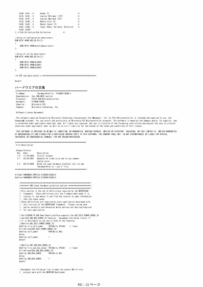
ハードウエアの定義/********************************************************************
FileName: HardwareProfile - PICDEM FSUSB.h
Dependencies: See INCLUDES section
Processor: PIC18 USB Microcontrollers
Hardware: PICDEM FSUSB
Compiler: Microchip C18
Company: Microchip Technology, Inc.
Software License Agreement:
The software supplied herewith by Microchip Technology Incorporated (the 鼎ompany・ for its PICョ Microcontroller is intended and supplied to you, the
Company痴 customer, for use solely and exclusively on Microchip PIC Microcontroller products. The software is owned by the Company and/or its supplier, and
is protected under applicable copyright laws. All rights are reserved. Any use in violation of the foregoing restrictions may subject the user to criminal
sanctions under applicable laws, as well as to civil liability for the breach of the terms and conditions of this license.
THIS SOFTWARE IS PROVIDED IN AN 鄭S IS・CONDITION. NO WARRANTIES, WHETHER EXPRESS, IMPLIED OR STATUTORY, INCLUDING, BUT NOT LIMITED TO, IMPLIED WARRANTIES
OF MERCHANTABILITY AND FITNESS FOR A PARTICULAR PURPOSE APPLY TO THIS SOFTWARE. THE COMPANY SHALL NOT, IN ANY CIRCUMSTANCES, BE LIABLE FOR SPECIAL,
INCIDENTAL OR CONSEQUENTIAL DAMAGES, FOR ANY REASON WHATSOEVER.
********************************************************************
File Description:
Change History:
Rev Date Description
1.0 11/19/2004 Initial release
2.1 02/26/2007 Updated for simplicity and to use common
coding style
2.3 09/15/2008 Broke out each hardware platform into its own
"HardwareProfile - xxx.h" file
********************************************************************/
#ifndef HARDWARE_PROFILE_PICDEM_FSUSB_H
#define HARDWARE_PROFILE_PICDEM_FSUSB_H
/*******************************************************************/
/******** USB stack hardware selection options *********************/
/*******************************************************************/
//This section is the set of definitions required by the MCHPFSUSB
// framework. These definitions tell the firmware what mode it is
// running in, and where it can find the results to some information
// that the stack needs.
//These definitions are required by every application developed with
// this revision of the MCHPFSUSB framework. Please review each
// option carefully and determine which options are desired/required
// for your application.
//The PICDEM FS USB Demo Board platform supports the USE_SELF_POWER_SENSE_IO
//and USE_USB_BUS_SENSE_IO features. Uncomment the below line(s) if
//it is desireable to use one or both of the features.
//#define USE_SELF_POWER_SENSE_IO
#define tris_self_power TRISAbits.TRISA2 // Input
#if defined(USE_SELF_POWER_SENSE_IO)
#define self_power PORTAbits.RA2
#else
#define self_power 1
#endif
//#define USE_USB_BUS_SENSE_IO
#define tris_usb_bus_sense TRISAbits.TRISA1 // Input
#if defined(USE_USB_BUS_SENSE_IO)
#define USB_BUS_SENSE PORTAbits.RA1
#else
#define USB_BUS_SENSE 1
#endif
//Uncomment the following line to make the output HEX of this
// project work with the MCHPUSB Bootloader
PIC - 23 ページ

//#define PROGRAMMABLE_WITH_USB_MCHPUSB_BOOTLOADER
//Uncomment the following line to make the output HEX of this
// project work with the HID Bootloader
//#define PROGRAMMABLE_WITH_USB_HID_BOOTLOADER
#define PROGRAMMABLE_WITH_USB_MCHPUSB_BOOTLOADER
/*******************************************************************/
/*******************************************************************/
/*******************************************************************/
/******** Application specific definitions *************************/
/*******************************************************************/
/*******************************************************************/
/*******************************************************************/
/** Board definition ***********************************************/
//These defintions will tell the main() function which board is
// currently selected. This will allow the application to add
// the correct configuration bits as wells use the correct
// initialization functions for the board. These defitions are only
// required in the stack provided demos. They are not required in
// final application design.
#define DEMO_BOARD PICDEM_FS_USB
#define PICDEM_FS_USB
#define CLOCK_FREQ 48000000
/** LED ************************************************************/
#define mInitAllLEDs() LATC &= 0xFC; TRISC &= 0xFC;
#define mLED_1 LATCbits.LATC0
#define mLED_2 LATCbits.LATC1
//yu#define mLED_3 LATDbits.LATC0
//yu#define mLED_4 LATDbits.LATC1
#define mGetLED_1() mLED_1
#define mGetLED_2() mLED_2
//yu#define mGetLED_3() mLED_3
//yu#define mGetLED_4() mLED_4
#define mLED_1_On() mLED_1 = 1;
#define mLED_2_On() mLED_2 = 1;
//yu#define mLED_3_On() mLED_3 = 1;
//yu#define mLED_4_On() mLED_4 = 1;
#define mLED_1_Off() mLED_1 = 0;
#define mLED_2_Off() mLED_2 = 0;
//yu #define mLED_3_Off() mLED_3 = 0;
//yu#define mLED_4_Off() mLED_4 = 0;
#define mLED_1_Toggle() mLED_1 = !mLED_1;
#define mLED_2_Toggle() mLED_2 = !mLED_2;
//yu#define mLED_3_Toggle() mLED_3 = !mLED_3;
//yu#define mLED_4_Toggle() mLED_4 = !mLED_4;
/** SWITCH *********************************************************/
#define mInitAllSwitches() TRISCbits.TRISC2=1; //yu TRISBbits.TRISB5=1;
//yu #define mInitSwitch2() TRISBbits.TRISB4=1;
#define mInitSwitch3() TRISCbits.TRISC2=1;
//yu #define sw2 PORTBbits.RB4
#define sw3 PORTCbits.RC2
/** USB external transceiver interface (optional) ******************/
//yu #define tris_usb_vpo TRISBbits.TRISB3 // Output
//yu #define tris_usb_vmo TRISBbits.TRISB2 // Output
//yu #define tris_usb_rcv TRISAbits.TRISA4 // Input
//yu #define tris_usb_vp TRISCbits.TRISC5 // Input
//yu #define tris_usb_vm TRISCbits.TRISC4 // Input
//yu #define tris_usb_oe TRISCbits.TRISC1 // Output
//yu #define tris_usb_suspnd TRISAbits.TRISA3 // Output
/** I/O pin definitions ********************************************/
#define INPUT_PIN 1
#define OUTPUT_PIN 0
#endif //HARDWARE_PROFILE_PICDEM_FSUSB_H
リンク配置// $Id: 18f4550.lkr,v 1.1.2.2 2004/04/28 00:41:31 curtiss Exp $
// File: rm18f4550.lkr
// Sample linker script for the PIC18F4550 processor WITH BOOTLOADER
LIBPATH .
FILES c018i.o
FILES clib.lib
FILES p18f2550.lib
CODEPAGE NAME=boot START=0x0 END=0x7FF PROTECTED
CODEPAGE NAME=vectors START=0x800 END=0x829 PROTECTED
CODEPAGE NAME=page START=0x82A END=0x7FFF
CODEPAGE NAME=idlocs START=0x200000 END=0x200007 PROTECTED
CODEPAGE NAME=config START=0x300000 END=0x30000D PROTECTED
CODEPAGE NAME=devid START=0x3FFFFE END=0x3FFFFF PROTECTED
CODEPAGE NAME=eedata START=0xF00000 END=0xF000FF PROTECTED
PIC - 24 ページ

ACCESSBANK NAME=accessram START=0x0 END=0x5F
DATABANK NAME=gpr0 START=0x60 END=0xFF
DATABANK NAME=gpr1 START=0x100 END=0x1FF
DATABANK NAME=gpr2 START=0x200 END=0x2FF
DATABANK NAME=gpr3 START=0x300 END=0x3FF
DATABANK NAME=usb4 START=0x400 END=0x4FF PROTECTED
DATABANK NAME=usb5 START=0x500 END=0x5FF PROTECTED
DATABANK NAME=usb6 START=0x600 END=0x6FF PROTECTED
DATABANK NAME=usb7 START=0x700 END=0x7FF PROTECTED
ACCESSBANK NAME=accesssfr START=0xF60 END=0xFFF PROTECTED
SECTION NAME=CONFIG ROM=config
STACK SIZE=0x100 RAM=gpr3
プログラム/********************************************************************
FileName: mouse.c
Dependencies: See INCLUDES section
Processor: PIC18, PIC24, and PIC32 USB Microcontrollers
Hardware: This demo is natively intended to be used on Microchip USB demo
boards supported by the MCHPFSUSB stack. See release notes for
support matrix. This demo can be modified for use on other hardware
platforms.
Complier: Microchip C18 (for PIC18), C30 (for PIC24), C32 (for PIC32)
Company: Microchip Technology, Inc.
Software License Agreement:
The software supplied herewith by Microchip Technology Incorporated (the 鼎ompany・ for its PICョ Microcontroller is intended and supplied to you, the
Company痴 customer, for use solely and exclusively on Microchip PIC Microcontroller products. The software is owned by the Company and/or its supplier, and
is protected under applicable copyright laws. All rights are reserved. Any use in violation of the foregoing restrictions may subject the user to criminal
sanctions under applicable laws, as well as to civil liability for the breach of the terms and conditions of this license.
THIS SOFTWARE IS PROVIDED IN AN 鄭S IS・CONDITION. NO WARRANTIES, WHETHER EXPRESS, IMPLIED OR STATUTORY, INCLUDING, BUT NOT LIMITED TO, IMPLIED WARRANTIES
OF MERCHANTABILITY AND FITNESS FOR A PARTICULAR PURPOSE APPLY TO THIS SOFTWARE. THE COMPANY SHALL NOT, IN ANY CIRCUMSTANCES, BE LIABLE FOR SPECIAL,
NCIDENTAL OR CONSEQUENTIAL DAMAGES, FOR ANY REASON WHATSOEVER.
********************************************************************
File Description:
Change History:
Rev Description
---- -----------------------------------------
1.0 Initial release
2.1 Updated for simplicity and to use common coding style
2.6a Updated to allow screen savers to come on by only sending
one packet indicating no movement and then allowing the
endpoint to NAK until the next time movement is registered.
2.7 Added example to put PIC24F devices to sleep using USB
activity to wake the device back up.
********************************************************************/
#ifndef USBMOUSE_C
#define USBMOUSE_C
/** INCLUDES *******************************************************/
#include "./USB/usb.h"
#include "HardwareProfile.h"
#include "./USB/usb_function_hid.h"
/** CONFIGURATION **************************************************/
/** VARIABLES ******************************************************/
#pragma udata
BYTE old_sw2,old_sw3;
BOOL emulate_mode;
BYTE movement_length;
BYTE vector = 0;
char buffer[3];
USB_HANDLE lastTransmission;
//The direction that the mouse will move in
ROM signed char dir_table[]={-4,-4,-4, 0, 4, 4, 4, 0};
/** PRIVATE PROTOTYPES *********************************************/
void BlinkUSBStatus(void);
BOOL Switch2IsPressed(void);
BOOL Switch3IsPressed(void);
void Emulate_Mouse(void);
static void InitializeSystem(void);
void ProcessIO(void);
void UserInit(void);
void YourHighPriorityISRCode();
void YourLowPriorityISRCode();
/** VECTOR REMAPPING ***********************************************/
//On PIC18 devices, addresses 0x00, 0x08, and 0x18 are used for
//the reset, high priority interrupt, and low priority interrupt
//vectors. However, the current Microchip USB bootloader
//examples are intended to occupy addresses 0x00-0x7FF or
//0x00-0xFFF depending on which bootloader is used. Therefore,
#if defined(__18CXX)
PIC - 25 ページ

//the bootloader code remaps these vectors to new locations
//as indicated below. This remapping is only necessary if you
//wish to program the hex file generated from this project with
//the USB bootloader. If no bootloader is used, edit the
//usb_config.h file and comment out the following defines:
//#define PROGRAMMABLE_WITH_USB_HID_BOOTLOADER
//#define PROGRAMMABLE_WITH_USB_LEGACY_CUSTOM_CLASS_BOOTLOADER
#define REMAPPED_RESET_VECTOR_ADDRESS 0x1000
#define REMAPPED_HIGH_INTERRUPT_VECTOR_ADDRESS 0x1008
#define REMAPPED_LOW_INTERRUPT_VECTOR_ADDRESS 0x1018
#if defined(PROGRAMMABLE_WITH_USB_HID_BOOTLOADER)
#define REMAPPED_RESET_VECTOR_ADDRESS 0x800
#define REMAPPED_HIGH_INTERRUPT_VECTOR_ADDRESS 0x808
#define REMAPPED_LOW_INTERRUPT_VECTOR_ADDRESS 0x818
#elif defined(PROGRAMMABLE_WITH_USB_MCHPUSB_BOOTLOADER)
#define REMAPPED_RESET_VECTOR_ADDRESS 0x00
#define REMAPPED_HIGH_INTERRUPT_VECTOR_ADDRESS 0x08
#define REMAPPED_LOW_INTERRUPT_VECTOR_ADDRESS 0x18
#else
#endif
#if defined(PROGRAMMABLE_WITH_USB_HID_BOOTLOADER)||defined(PROGRAMMABLE_WITH_USB_MCHPUSB_BOOTLOADER)
extern void _startup (void); // See c018i.c in your C18 compiler dir
#pragma code REMAPPED_RESET_VECTOR = REMAPPED_RESET_VECTOR_ADDRESS
void _reset (void)
{
_asm goto _startup _endasm
}
#endif
#pragma code REMAPPED_HIGH_INTERRUPT_VECTOR = REMAPPED_HIGH_INTERRUPT_VECTOR_ADDRESS
void Remapped_High_ISR (void)
{
_asm goto YourHighPriorityISRCode _endasm
}
#pragma code REMAPPED_LOW_INTERRUPT_VECTOR = REMAPPED_LOW_INTERRUPT_VECTOR_ADDRESS
void Remapped_Low_ISR (void)
{
_asm goto YourLowPriorityISRCode _endasm
}
#if defined(PROGRAMMABLE_WITH_USB_HID_BOOTLOADER)||defined(PROGRAMMABLE_WITH_USB_MCHPUSB_BOOTLOADER)
//Note: If this project is built while one of the bootloaders has
//been defined, but then the output hex file is not programmed with
//the bootloader, addresses 0x08 and 0x18 would end up programmed with 0xFFFF.
//As a result, if an actual interrupt was enabled and occured, the PC would jump
//to 0x08 (or 0x18) and would begin executing "0xFFFF" (unprogrammed space). This
//executes as nop instructions, but the PC would eventually reach the REMAPPED_RESET_VECTOR_ADDRESS
//(0x1000 or 0x800, depending upon bootloader), and would execute the "goto _startup". This
//would effective reset the application.
//To fix this situation, we should always deliberately place a
//"goto REMAPPED_HIGH_INTERRUPT_VECTOR_ADDRESS" at address 0x08, and a
//"goto REMAPPED_LOW_INTERRUPT_VECTOR_ADDRESS" at address 0x18. When the output
//hex file of this project is programmed with the bootloader, these sections do not
//get bootloaded (as they overlap the bootloader space). If the output hex file is not
//programmed using the bootloader, then the below goto instructions do get programmed,
//and the hex file still works like normal. The below section is only required to fix this
//scenario.
#pragma code HIGH_INTERRUPT_VECTOR = 0x08
void High_ISR (void)
{
_asm goto REMAPPED_HIGH_INTERRUPT_VECTOR_ADDRESS _endasm
}
#pragma code LOW_INTERRUPT_VECTOR = 0x18
void Low_ISR (void)
{
_asm goto REMAPPED_LOW_INTERRUPT_VECTOR_ADDRESS _endasm
}
#endif //end of "#if defined(PROGRAMMABLE_WITH_USB_HID_BOOTLOADER)||defined(PROGRAMMABLE_WITH_USB_LEGACY_CUSTOM_CLASS_BOOTLOADER)"
#pragma code
//These are your actual interrupt handling routines.
#pragma interrupt YourHighPriorityISRCode
void YourHighPriorityISRCode()
//Check which interrupt flag caused the interrupt.
//Service the interrupt
//Clear the interrupt flag
//Etc.
{
USBDeviceTasks();
#if defined(USB_INTERRUPT)
} //This return will be a "retfie fast", since this is in a #pragma interrupt section
#pragma interruptlow YourLowPriorityISRCode
void YourLowPriorityISRCode()
//Check which interrupt flag caused the interrupt.
//Service the interrupt
//Clear the interrupt flag
//Etc.
{
} //This return will be a "retfie", since this is in a #pragma interruptlow section
#endif
PIC - 26 ページ

#endif
/** DECLARATIONS ***************************************************/
#pragma code
/********************************************************************
* Function: void main(void)
*
* PreCondition: None
*
* Input: None
*
* Output: None
*
* Side Effects: None
*
* Overview: Main program entry point.
*
* Note: None
*******************************************************************/
#if defined(__18CXX)
void main(void)
#else
int main(void)
#endif
{
InitializeSystem();
#if defined(USB_INTERRUPT)
USBDeviceAttach();
#endif
while(1)
{
// Check bus status and service USB interrupts.
#if defined(USB_POLLING)
USBDeviceTasks(); // Interrupt or polling method. If using polling, must call
// this function periodically. This function will take care
// of processing and responding to SETUP transactions
// (such as during the enumeration process when you first
// plug in). USB hosts require that USB devices should accept
// and process SETUP packets in a timely fashion. Therefore,
// when using polling, this function should be called
// frequently (such as once about every 100 microseconds) at any
// time that a SETUP packet might reasonably be expected to
// be sent by the host to your device. In most cases, the
// USBDeviceTasks() function does not take very long to
// execute (~50 instruction cycles) before it returns.
#endif
// Application-specific tasks.
// Application related code may be added here, or in the ProcessIO() function.
ProcessIO();
}//end while
}//end main
/********************************************************************
* Function: static void InitializeSystem(void)
*
* PreCondition: None
*
* Input: None
*
* Output: None
*
* Side Effects: None
*
* Overview: InitializeSystem is a centralize initialization
* routine. All required USB initialization routines
* are called from here.
*
* User application initialization routine should
* also be called from here.
*
* Note: None
*******************************************************************/
static void InitializeSystem(void)
{
#if (defined(__18CXX) & !defined(PIC18F87J50_PIM))
ADCON1 |= 0x0F; // Default all pins to digital
#elif defined(__C30__)
#if defined(__PIC24FJ256GB110__) || defined(__PIC24FJ256GB106__)
AD1PCFGL = 0xFFFF;
#endif
#elif defined(__C32__)
AD1PCFG = 0xFFFF;
#endif
//On the PIC18F87J50 Family of USB microcontrollers, the PLL will not power up and be enabled
//by default, even if a PLL enabled oscillator configuration is selected (such as HS+PLL).
#if defined(PIC18F87J50_PIM) || defined(PIC18F46J50_PIM) || defined(PIC18F_STARTER_KIT_1) || defined(PIC18F47J53_PIM)
PIC - 27 ページ

//by default, even if a PLL enabled oscillator configuration is selected (such as HS+PLL).
//This allows the device to power up at a lower initial operating frequency, which can be
//advantageous when powered from a source which is not gauranteed to be adequate for 48MHz
//operation. On these devices, user firmware needs to manually set the OSCTUNE<PLLEN> bit to
//power up the PLL.
{
unsigned int pll_startup_counter = 600;
OSCTUNEbits.PLLEN = 1; //Enable the PLL and wait 2+ms until the PLL locks before enabling USB module
while(pll_startup_counter--);
}
//Device switches over automatically to PLL output after PLL is locked and ready.
#endif
//Configure all I/O pins to use digital input buffers. The PIC18F87J50 Family devices
//use the ANCONx registers to control this, which is different from other devices which
//use the ADCON1 register for this purpose.
#if defined(PIC18F87J50_PIM)
WDTCONbits.ADSHR = 1; // Select alternate SFR location to access ANCONx registers
ANCON0 = 0xFF; // Default all pins to digital
ANCON1 = 0xFF; // Default all pins to digital
WDTCONbits.ADSHR = 0; // Select normal SFR locations
#endif
//Configure all I/O pins to use digital input buffers. The PIC18F87J50 Family devices
//use the ANCONx registers to control this, which is different from other devices which
//use the ADCON1 register for this purpose.
#if defined(PIC18F46J50_PIM) || defined(PIC18F_STARTER_KIT_1) || defined(PIC18F47J53_PIM)
ANCON0 = 0xFF; // Default all pins to digital
ANCON1 = 0xFF; // Default all pins to digital
#endif
//On the PIC24FJ64GB004 Family of USB microcontrollers, the PLL will not power up and be enabled
//by default, even if a PLL enabled oscillator configuration is selected (such as HS+PLL).
//This allows the device to power up at a lower initial operating frequency, which can be
//advantageous when powered from a source which is not gauranteed to be adequate for 32MHz
//operation. On these devices, user firmware needs to manually set the CLKDIV<PLLEN> bit to
//power up the PLL.
#if defined(PIC24FJ64GB004_PIM) || defined(PIC24FJ256DA210_DEV_BOARD)
{
unsigned int pll_startup_counter = 600;
CLKDIVbits.PLLEN = 1;
while(pll_startup_counter--);
}
//Device switches over automatically to PLL output after PLL is locked and ready.
#endif
// The USB specifications require that USB peripheral devices must never source
// current onto the Vbus pin. Additionally, USB peripherals should not source
// current on D+ or D- when the host/hub is not actively powering the Vbus line.
// When designing a self powered (as opposed to bus powered) USB peripheral
// device, the firmware should make sure not to turn on the USB module and D+
// or D- pull up resistor unless Vbus is actively powered. Therefore, the
// firmware needs some means to detect when Vbus is being powered by the host.
// A 5V tolerant I/O pin can be connected to Vbus (through a resistor), and
// can be used to detect when Vbus is high (host actively powering), or low
// (host is shut down or otherwise not supplying power). The USB firmware
// can then periodically poll this I/O pin to know when it is okay to turn on
// the USB module/D+/D- pull up resistor. When designing a purely bus powered
// peripheral device, it is not possible to source current on D+ or D- when the
// host is not actively providing power on Vbus. Therefore, implementing this
// bus sense feature is optional. This firmware can be made to use this bus
// sense feature by making sure "USE_USB_BUS_SENSE_IO" has been defined in the
// HardwareProfile.h file.
#if defined(USE_USB_BUS_SENSE_IO)
tris_usb_bus_sense = INPUT_PIN; // See HardwareProfile.h
#endif
// If the host PC sends a GetStatus (device) request, the firmware must respond
// and let the host know if the USB peripheral device is currently bus powered
// or self powered. See chapter 9 in the official USB specifications for details
// regarding this request. If the peripheral device is capable of being both
// self and bus powered, it should not return a hard coded value for this request.
// Instead, firmware should check if it is currently self or bus powered, and
// respond accordingly. If the hardware has been configured like demonstrated
// on the PICDEM FS USB Demo Board, an I/O pin can be polled to determine the
// currently selected power source. On the PICDEM FS USB Demo Board, "RA2"
// is used for this purpose. If using this feature, make sure "USE_SELF_POWER_SENSE_IO"
// has been defined in HardwareProfile.h, and that an appropriate I/O pin has been mapped
// to it in HardwareProfile.h.
#if defined(USE_SELF_POWER_SENSE_IO)
tris_self_power = INPUT_PIN; // See HardwareProfile.h
#endif
UserInit();
USBDeviceInit(); //usb_device.c. Initializes USB module SFRs and firmware
//variables to known states.
}//end InitializeSystem
/******************************************************************************
* Function: void UserInit(void)
*
* PreCondition: None
PIC - 28 ページ
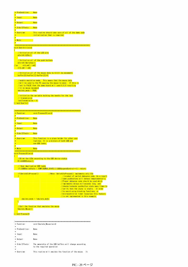
* PreCondition: None
*
* Input: None
*
* Output: None
*
* Side Effects: None
*
* Overview: This routine should take care of all of the demo code
* initialization that is required.
*
* Note:
*
*****************************************************************************/
void UserInit(void)
{
//Initialize all of the LED pins
mInitAllLEDs();
//Initialize all of the push buttons
mInitAllSwitches();
//yu old_sw2 = sw2;
old_sw3 = sw3;
//Initialize all of the mouse data to 0,0,0 (no movement)
buffer[0]=buffer[1]=buffer[2]=0;
//enable emulation mode. This means that the mouse data
//will be send to the PC causing the mouse to move. If this is
//set to FALSE then the demo board will send 0,0,0 resulting
//in no mouse movement
emulate_mode = TRUE;
//initialize the variable holding the handle for the last
// transmission
lastTransmission = 0;
}//end UserInit
/********************************************************************
* Function: void ProcessIO(void)
*
* PreCondition: None
*
* Input: None
*
* Output: None
*
* Side Effects: None
*
* Overview: This function is a place holder for other user
* routines. It is a mixture of both USB and
* non-USB tasks.
*
* Note: None
*******************************************************************/
void ProcessIO(void)
{
//Blink the LEDs according to the USB device status
BlinkUSBStatus();
// User Application USB tasks
if((USBDeviceState < CONFIGURED_STATE)||(USBSuspendControl==1)) return;
if(Switch3IsPressed()) //Note: Switch3IsPressed() implements only the
//some pusbbuttons will behave temperamentally.
//Proper debounce code should be used which
//implements delays millseconds long, and
//checks/reckecks pushbutton state many times to
//verify that the state is stable. In order
//to avoid using blocking functions, or
//microcontroller timer resources this feature
//is not implemented in this example.
{ //crudest of switch debounce code. As a result
emulate_mode = !emulate_mode;
}
//Call the function that emulates the mouse
Emulate_Mouse();
}//end ProcessIO
/******************************************************************************
* Function: void Emulate_Mouse(void)
*
* PreCondition: None
*
* Input: None
*
* Output: None
*
* Side Effects: The ownership of the USB buffers will change according
* to the required operation
*
* Overview: This routine will emulate the function of the mouse. It
* does this by sending IN packets of data to the host.
PIC - 29 ページ

* does this by sending IN packets of data to the host.
*
* The generic function HIDTxPacket() is used to send HID
* IN packets over USB to the host.
*
* Note:
*
*****************************************************************************/
void Emulate_Mouse(void)
{
static BOOL sent_dont_move = FALSE;
if(emulate_mode == TRUE)
{
sent_dont_move = FALSE;
//go 14 times in the same direction before changing direction
if(movement_length > 14)
{
buffer[0] = 0;
buffer[1] = dir_table[vector & 0x07]; // X-Vector
buffer[2] = dir_table[(vector+2) & 0x07]; // Y-Vector
//go to the next direction in the table
vector++;
//reset the counter for when to change again
movement_length = 0;
}//end if(movement_length > 14)
}
else
{
//don't move the mouse
buffer[0] = buffer[1] = buffer[2] = 0;
}
if(HIDTxHandleBusy(lastTransmission) == 0)
{
//copy over the data to the HID buffer
hid_report_in[0] = buffer[0];
hid_report_in[1] = buffer[1];
hid_report_in[2] = buffer[2];
if(((sent_dont_move == FALSE) && (emulate_mode == FALSE)) || (emulate_mode == TRUE))
{
//Send the 3 byte packet over USB to the host.
lastTransmission = HIDTxPacket(HID_EP, (BYTE*)hid_report_in, 0x03);
//increment the counter of when to change the data sent
movement_length++;
sent_dont_move = TRUE;
}
}
}//end Emulate_Mouse
/******************************************************************************
* Function: BOOL Switch2IsPressed(void)
*
* PreCondition: None
*
* Input: None
*
* Output: TRUE - pressed, FALSE - not pressed
*
* Side Effects: None
*
* Overview: Indicates if the switch is pressed.
*
* Note:
*
*****************************************************************************/
/** del yu
BOOL Switch2IsPressed(void)
{
if(sw2 != old_sw2)
{
old_sw2 = sw2; // Save new value
if(sw2 == 0) // If pressed
return TRUE; // Was pressed
}//end if
return FALSE; // Was not pressed
}//end Switch2IsPressed
**/
/******************************************************************************
* Function: BOOL Switch3IsPressed(void)
*
* PreCondition: None
*
* Input: None
*
* Output: TRUE - pressed, FALSE - not pressed
*
* Side Effects: None
*
* Overview: Indicates if the switch is pressed.
PIC - 30 ページ
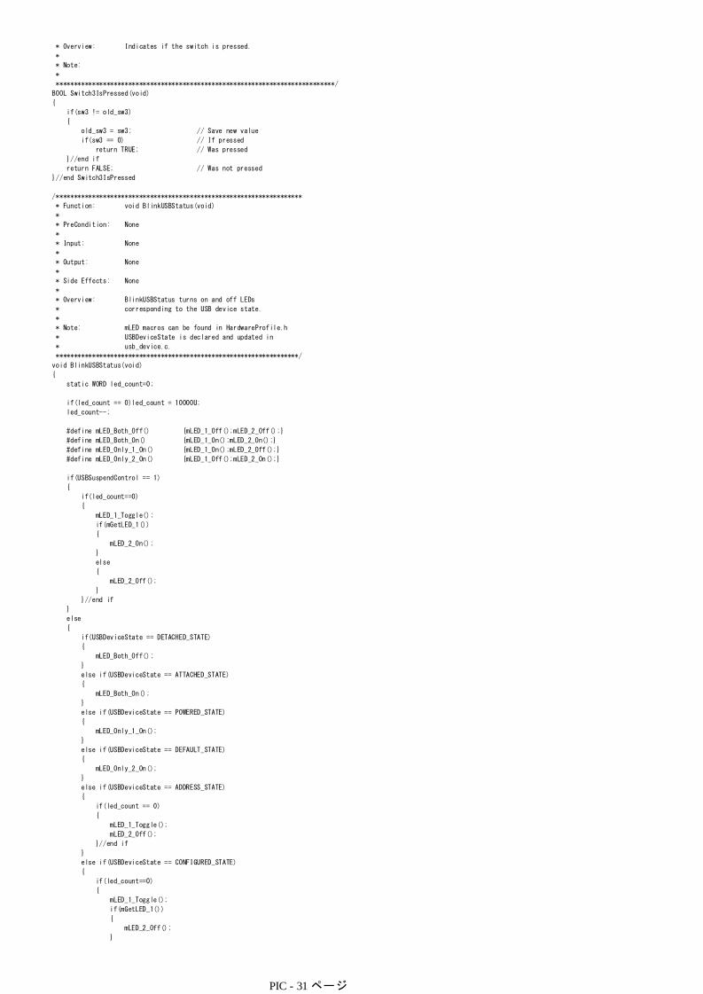
* Overview: Indicates if the switch is pressed.
*
* Note:
*
*****************************************************************************/
BOOL Switch3IsPressed(void)
{
if(sw3 != old_sw3)
{
old_sw3 = sw3; // Save new value
if(sw3 == 0) // If pressed
return TRUE; // Was pressed
}//end if
return FALSE; // Was not pressed
}//end Switch3IsPressed
/********************************************************************
* Function: void BlinkUSBStatus(void)
*
* PreCondition: None
*
* Input: None
*
* Output: None
*
* Side Effects: None
*
* Overview: BlinkUSBStatus turns on and off LEDs
* corresponding to the USB device state.
*
* Note: mLED macros can be found in HardwareProfile.h
* USBDeviceState is declared and updated in
* usb_device.c.
*******************************************************************/
void BlinkUSBStatus(void)
{
static WORD led_count=0;
if(led_count == 0)led_count = 10000U;
led_count--;
#define mLED_Both_Off() {mLED_1_Off();mLED_2_Off();}
#define mLED_Both_On() {mLED_1_On();mLED_2_On();}
#define mLED_Only_1_On() {mLED_1_On();mLED_2_Off();}
#define mLED_Only_2_On() {mLED_1_Off();mLED_2_On();}
if(USBSuspendControl == 1)
{
if(led_count==0)
{
mLED_1_Toggle();
if(mGetLED_1())
{
mLED_2_On();
}
else
{
mLED_2_Off();
}
}//end if
}
else
{
if(USBDeviceState == DETACHED_STATE)
{
mLED_Both_Off();
}
else if(USBDeviceState == ATTACHED_STATE)
{
mLED_Both_On();
}
else if(USBDeviceState == POWERED_STATE)
{
mLED_Only_1_On();
}
else if(USBDeviceState == DEFAULT_STATE)
{
mLED_Only_2_On();
}
else if(USBDeviceState == ADDRESS_STATE)
{
if(led_count == 0)
{
mLED_1_Toggle();
mLED_2_Off();
}//end if
}
else if(USBDeviceState == CONFIGURED_STATE)
{
if(led_count==0)
{
mLED_1_Toggle();
if(mGetLED_1())
{
mLED_2_Off();
}
else
PIC - 31 ページ

else
{
mLED_2_On();
}
}//end if
}
}
// // No need to clear UIRbits.SOFIF to 0 here.
// // Callback caller is already doing that.
// #define BLINK_INTERVAL 20000
// #define BLANK_INTERVAL 200000
//
// static WORD blink_count=0;
// static DWORD loop_count = 0;
//
// if(loop_count == 0)
// {
// if(blink_count != 0)
// {
// loop_count = BLINK_INTERVAL;
// if(mGetLED_1())
// {
// mLED_1_Off();
// blink_count--;
// }
// else
// {
// mLED_1_On();
// }
// }
// else
// {
// loop_count = BLANK_INTERVAL;
// switch(USBDeviceState)
// {
// case ATTACHED_STATE:
// blink_count = 1;
// break;
// case POWERED_STATE:
// blink_count = 2;
// break;
// case DEFAULT_STATE:
// blink_count = 3;
// break;
// case ADR_PENDING_STATE:
// blink_count = 4;
// break;
// case ADDRESS_STATE:
// blink_count = 5;
// break;
// case CONFIGURED_STATE:
// blink_count = 6;
// break;
// case DETACHED_STATE:
// //fall through
// default:
// blink_count = 0;
// break;
// }
// }
// }
// else
// {
// loop_count--;
// }
}//end BlinkUSBStatus
// ******************************************************************************************************
// ************** USB Callback Functions ****************************************************************
// ******************************************************************************************************
// The USB firmware stack will call the callback functions USBCBxxx() in response to certain USB related
// events. For example, if the host PC is powering down, it will stop sending out Start of Frame (SOF)
// packets to your device. In response to this, all USB devices are supposed to decrease their power
// consumption from the USB Vbus to <2.5mA each. The USB module detects this condition (which according
// to the USB specifications is 3+ms of no bus activity/SOF packets) and then calls the USBCBSuspend()
// function. You should modify these callback functions to take appropriate actions for each of these
// conditions. For example, in the USBCBSuspend(), you may wish to add code that will decrease power
// consumption from Vbus to <2.5mA (such as by clock switching, turning off LEDs, putting the
// microcontroller to sleep, etc.). Then, in the USBCBWakeFromSuspend() function, you may then wish to
// add code that undoes the power saving things done in the USBCBSuspend() function.
// The USBCBSendResume() function is special, in that the USB stack will not automatically call this
// function. This function is meant to be called from the application firmware instead. See the
// additional comments near the function.
/******************************************************************************
* Function: void USBCBSuspend(void)
*
* PreCondition: None
*
* Input: None
*
* Output: None
PIC - 32 ページ

* Output: None
*
* Side Effects: None
*
* Overview: Call back that is invoked when a USB suspend is detected
*
* Note: None
*****************************************************************************/
void USBCBSuspend(void)
//Example power saving code. Insert appropriate code here for the desired
//application behavior. If the microcontroller will be put to sleep, a
//process similar to that shown below may be used:
//ConfigureIOPinsForLowPower();
//SaveStateOfAllInterruptEnableBits();
//DisableAllInterruptEnableBits();
//EnableOnlyTheInterruptsWhichWillBeUsedToWakeTheMicro(); //should enable at least USBActivityIF as a wake source
//Sleep();
//RestoreStateOfAllPreviouslySavedInterruptEnableBits(); //Preferrably, this should be done in the USBCBWakeFromSuspend() function instead.
//RestoreIOPinsToNormal(); //Preferrably, this should be done in the
USBCBWakeFromSuspend() function instead.
{
//IMPORTANT NOTE: Do not clear the USBActivityIF (ACTVIF) bit here. This bit is
//cleared inside the usb_device.c file. Clearing USBActivityIF here will cause
//things to not work as intended.
#if defined(__C30__)
_IPL = 7;
USBSleepOnSuspend();
_IPL = 0;
#endif
}
/******************************************************************************
* Function: void USBCBWakeFromSuspend(void)
*
* PreCondition: None
*
* Input: None
*
* Output: None
*
* Side Effects: None
*
* Overview: The host may put USB peripheral devices in low power
* suspend mode (by "sending" 3+ms of idle). Once in suspend
* mode, the host may wake the device back up by sending non-
* idle state signalling.
*
* This call back is invoked when a wakeup from USB suspend
* is detected.
*
* Note: None
*****************************************************************************/
void USBCBWakeFromSuspend(void)
// If clock switching or other power savings measures were taken when
// executing the USBCBSuspend() function, now would be a good time to
// switch back to normal full power run mode conditions. The host allows
// a few milliseconds of wakeup time, after which the device must be
// fully back to normal, and capable of receiving and processing USB
// packets. In order to do this, the USB module must receive proper
// clocking (IE: 48MHz clock must be available to SIE for full speed USB
// operation).
{
}
/********************************************************************
* Function: void USBCB_SOF_Handler(void)
*
* PreCondition: None
*
* Input: None
*
* Output: None
*
* Side Effects: None
*
* Overview: The USB host sends out a SOF packet to full-speed
* devices every 1 ms. This interrupt may be useful
* for isochronous pipes. End designers should
* implement callback routine as necessary.
*
* Note: None
*******************************************************************/
void USBCB_SOF_Handler(void)
{
// No need to clear UIRbits.SOFIF to 0 here.
// Callback caller is already doing that.
}
/*******************************************************************
* Function: void USBCBErrorHandler(void)
*
* PreCondition: None
*
PIC - 33 ページ
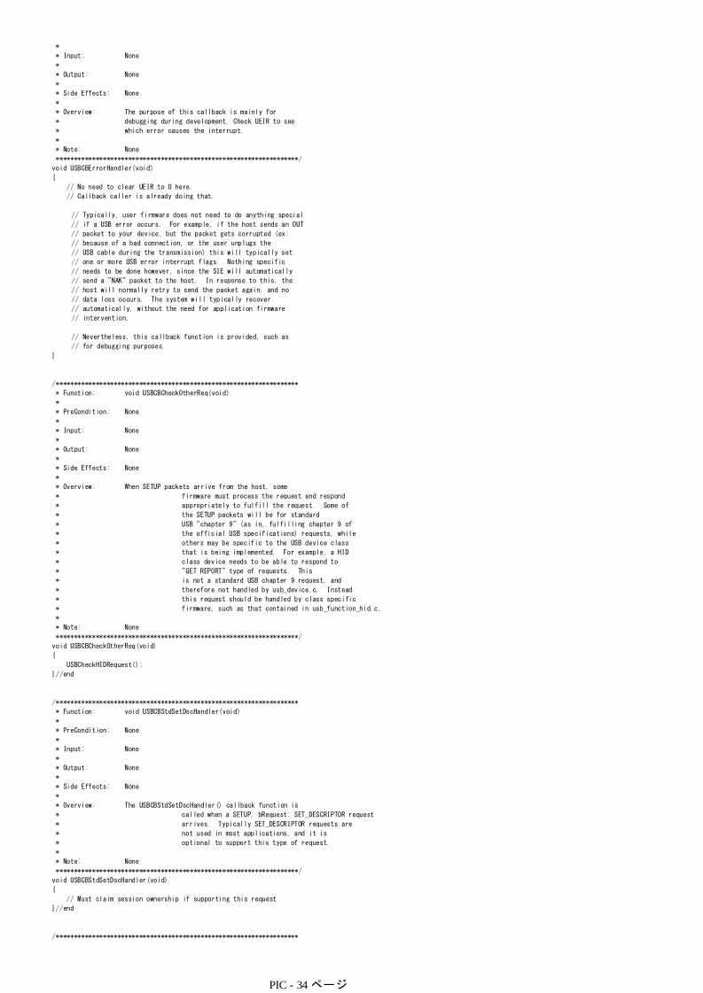
*
* Input: None
*
* Output: None
*
* Side Effects: None
*
* Overview: The purpose of this callback is mainly for
* debugging during development. Check UEIR to see
* which error causes the interrupt.
*
* Note: None
*******************************************************************/
void USBCBErrorHandler(void)
{
// No need to clear UEIR to 0 here.
// Callback caller is already doing that.
// Typically, user firmware does not need to do anything special
// if a USB error occurs. For example, if the host sends an OUT
// packet to your device, but the packet gets corrupted (ex:
// because of a bad connection, or the user unplugs the
// USB cable during the transmission) this will typically set
// one or more USB error interrupt flags. Nothing specific
// needs to be done however, since the SIE will automatically
// send a "NAK" packet to the host. In response to this, the
// host will normally retry to send the packet again, and no
// data loss occurs. The system will typically recover
// automatically, without the need for application firmware
// intervention.
// Nevertheless, this callback function is provided, such as
// for debugging purposes.
}
/*******************************************************************
* Function: void USBCBCheckOtherReq(void)
*
* PreCondition: None
*
* Input: None
*
* Output: None
*
* Side Effects: None
*
* Overview: When SETUP packets arrive from the host, some
* firmware must process the request and respond
* appropriately to fulfill the request. Some of
* the SETUP packets will be for standard
* USB "chapter 9" (as in, fulfilling chapter 9 of
* the official USB specifications) requests, while
* others may be specific to the USB device class
* that is being implemented. For example, a HID
* class device needs to be able to respond to
* "GET REPORT" type of requests. This
* is not a standard USB chapter 9 request, and
* therefore not handled by usb_device.c. Instead
* this request should be handled by class specific
* firmware, such as that contained in usb_function_hid.c.
*
* Note: None
*******************************************************************/
void USBCBCheckOtherReq(void)
{
USBCheckHIDRequest();
}//end
/*******************************************************************
* Function: void USBCBStdSetDscHandler(void)
*
* PreCondition: None
*
* Input: None
*
* Output: None
*
* Side Effects: None
*
* Overview: The USBCBStdSetDscHandler() callback function is
* called when a SETUP, bRequest: SET_DESCRIPTOR request
* arrives. Typically SET_DESCRIPTOR requests are
* not used in most applications, and it is
* optional to support this type of request.
*
* Note: None
*******************************************************************/
void USBCBStdSetDscHandler(void)
{
// Must claim session ownership if supporting this request
}//end
/*******************************************************************
* Function: void USBCBInitEP(void)
PIC - 34 ページ

* Function: void USBCBInitEP(void)
*
* PreCondition: None
*
* Input: None
*
* Output: None
*
* Side Effects: None
*
* Overview: This function is called when the device becomes
* initialized, which occurs after the host sends a
* SET_CONFIGURATION (wValue not = 0) request. This
* callback function should initialize the endpoints
* for the device's usage according to the current
* configuration.
*
* Note: None
*******************************************************************/
void USBCBInitEP(void)
{
//enable the HID endpoint
USBEnableEndpoint(HID_EP,USB_IN_ENABLED|USB_HANDSHAKE_ENABLED|USB_DISALLOW_SETUP);
}
/********************************************************************
* Function: void USBCBSendResume(void)
*
* PreCondition: None
*
* Input: None
*
* Output: None
*
* Side Effects: None
*
* Overview: The USB specifications allow some types of USB
* peripheral devices to wake up a host PC (such
* as if it is in a low power suspend to RAM state).
* This can be a very useful feature in some
* USB applications, such as an Infrared remote
* controlreceiver. If a user presses the "power"
* button on a remote control, it is nice that the
* IR receiver can detect this signalling, and then
* send a USB "command" to the PC to wake up.
*
* The USBCBSendResume() "callback" function is used
* to send this special USB signalling which wakes
* up the PC. This function may be called by
* application firmware to wake up the PC. This
* function should only be called when:
*
* 1. The USB driver used on the host PC supports
* the remote wakeup capability.
* 2. The USB configuration descriptor indicates
* the device is remote wakeup capable in the
* bmAttributes field.
* 3. The USB host PC is currently sleeping,
* and has previously sent your device a SET
* FEATURE setup packet which "armed" the
* remote wakeup capability.
*
* This callback should send a RESUME signal that
* has the period of 1-15ms.
*
* Note: Interrupt vs. Polling
* -Primary clock
* -Secondary clock ***** MAKE NOTES ABOUT THIS *******
* > Can switch to primary first by calling USBCBWakeFromSuspend()
* The modifiable section in this routine should be changed
* to meet the application needs. Current implementation
* temporary blocks other functions from executing for a
* period of 1-13 ms depending on the core frequency.
*
* According to USB 2.0 specification section 7.1.7.7,
* "The remote wakeup device must hold the resume signaling
* for at lest 1 ms but for no more than 15 ms."
* The idea here is to use a delay counter loop, using a
* common value that would work over a wide range of core
* frequencies.
* That value selected is 1800. See table below:
* ==========================================================
* Core Freq(MHz) MIP RESUME Signal Period (ms)
* ==========================================================
* 48 12 1.05
* 4 1 12.6
* ==========================================================
* * These timing could be incorrect when using code
* optimization or extended instruction mode,
* or when having other interrupts enabled.
* Make sure to verify using the MPLAB SIM's Stopwatch
* and verify the actual signal on an oscilloscope.
*******************************************************************/
void USBCBSendResume(void)
{
static WORD delay_count;
PIC - 35 ページ

static WORD delay_count;
USBResumeControl = 1; // Start RESUME signaling
delay_count = 1800U; // Set RESUME line for 1-13 ms
do
{
delay_count--;
}while(delay_count);
USBResumeControl = 0;
}
/*******************************************************************
* Function: BOOL USER_USB_CALLBACK_EVENT_HANDLER(
* USB_EVENT event, void *pdata, WORD size)
*
* PreCondition: None
*
* Input: USB_EVENT event - the type of event
* void *pdata - pointer to the event data
* WORD size - size of the event data
*
* Output: None
*
* Side Effects: None
*
* Overview: This function is called from the USB stack to
* notify a user application that a USB event
* occured. This callback is in interrupt context
* when the USB_INTERRUPT option is selected.
*
* Note: None
*******************************************************************/
BOOL USER_USB_CALLBACK_EVENT_HANDLER(USB_EVENT event, void *pdata, WORD size)
{
switch(event)
{
case EVENT_CONFIGURED:
USBCBInitEP();
break;
case EVENT_SET_DESCRIPTOR:
USBCBStdSetDscHandler();
break;
case EVENT_EP0_REQUEST:
USBCBCheckOtherReq();
break;
case EVENT_SOF:
USBCB_SOF_Handler();
break;
case EVENT_SUSPEND:
USBCBSuspend();
break;
case EVENT_RESUME:
USBCBWakeFromSuspend();
break;
case EVENT_BUS_ERROR:
USBCBErrorHandler();
break;
case EVENT_TRANSFER:
Nop();
break;
default:
break;
}
return TRUE;
}
/** EOF mouse.c *************************************************/
#endif
応用1Bootボタンを押すと
1回目 左へ
2回目 上へ
3回目 右へ
4回目 下へ
移動するプログラムを作成します
1.まず用意
前のプロジェクトを別のフォルダに保存します。ここではmouse2
2.確認(一旦ビルド)
3.ProcessIOの部分を書き換え
/********************************************************************
* Function: void ProcessIO(void)
*
* PreCondition: None
*
* Input: None
*
* Output: None
*
* Side Effects: None
*
* Overview: This function is a place holder for other user
* routines. It is a mixture of both USB and
PIC - 36 ページ

* non-USB tasks.
*
* Note: None
*******************************************************************/
void ProcessIO(void)
static int icase=0;
int ii;
{
//Blink the LEDs according to the USB device status
BlinkUSBStatus();
// User Application USB tasks
if((USBDeviceState < CONFIGURED_STATE)||(USBSuspendControl==1)) return;
if(Switch3IsPressed()) //Note: Switch3IsPressed() implements only the
//some pusbbuttons will behave temperamentally.
//Proper debounce code should be used which
//implements delays millseconds long, and
//checks/reckecks pushbutton state many times to
//verify that the state is stable. In order
//to avoid using blocking functions, or
//microcontroller timer resources this feature
//is not implemented in this example.
{ //crudest of switch debounce code. As a result
icase=1;
hid_report_in[0] = 0;
case 0:
switch(icase){
// emulate_mode = !emulate_mode;
hid_report_in[1] = -100;
lastTransmission = HIDTxPacket(HID_EP, (BYTE*)hid_report_in, 0x03);
hid_report_in[2] = 0;
icase=2;
hid_report_in[0] = 0;
case 1:
break;
hid_report_in[1] = 0;
lastTransmission = HIDTxPacket(HID_EP, (BYTE*)hid_report_in, 0x03);
hid_report_in[2] = -100;
icase=3;
hid_report_in[0] = 0;
case 2:
break;
hid_report_in[1] = 100;
lastTransmission = HIDTxPacket(HID_EP, (BYTE*)hid_report_in, 0x03);
hid_report_in[2] = 0;
icase=0;
hid_report_in[0] = 0;
case 3:
break;
hid_report_in[1] = 0;
lastTransmission = HIDTxPacket(HID_EP, (BYTE*)hid_report_in, 0x03);
hid_report_in[2] = 100;
}
break;
}
//Call the function that emulates the mouse
// Emulate_Mouse();
}//end ProcessIO
応用2 連打クリックを50回連打するプログラムを考えますvoid ProcessIO(void)
{
static int jj=0;
static int ii=0;
//Blink the LEDs according to the USB device status
BlinkUSBStatus();
// User Application USB tasks
if((USBDeviceState < CONFIGURED_STATE)||(USBSuspendControl==1)) return;
jj=100; //set 初期値
}
if(jj>0){
if(Switch3IsPressed()){
jj--;
hid_report_in[0] = 1;
hid_report_in[1] = 0;
if(ii==0){
if(HIDTxHandleBusy(lastTransmission) == 0) {
lastTransmission = HIDTxPacket(HID_EP, (BYTE*)hid_report_in, 0x03);
ii=1;
hid_report_in[0] = 0;
}else{
hid_report_in[2] = 0;
hid_report_in[1] = 0;
lastTransmission = HIDTxPacket(HID_EP, (BYTE*)hid_report_in, 0x03);
hid_report_in[2] = 0;
}
}
ii=0;
}
}//end ProcessIO
PIC - 37 ページ

}//end ProcessIO
PIC - 38 ページ