use of micro-pile inclusions to enhance foundation...
TRANSCRIPT
1st International Conference on Natural Hazards & Infrastructure
28-30 June, 2016, Chania, Greece
Use of Micro-Pile Inclusions to Enhance Foundation Rocking Isolation
M. Loli1, G. Gazetas National Technical University of Athens, Greece
J. A. Knappett University of Dundee, UK
I. Anastasopoulos ΕΤΗ Zuric, Switzerland
ABSTRACT
A preceding experimental study carried out at the University of Dundee, as well as independent experimental and
numerical research results, have shown the improved seismic performance of rocking shallow foundations in comparison
to conventional, conservatively designed foundations. By properly reducing the size of the footing, rocking behavior due
to seismic loading can occur about the footing base. It has been shown that rocking foundations can reduce seismic
ductility demand on bridge columns and improve bridge performance so much so as to enable them to safely resist very
strong seismic motions which lead to collapse of alternative conventional systems. Yet, key concern is the potential for
significant settlement accumulation, especially in relatively poor soil conditions. Therefore, current research objectives
focus on exploring possible innovative foundation systems that will optimize the seismic performance of rocking
foundations. Centrifuge model testing and 3D numerical modelling was employed to investigate the performance of
various hybrid foundation systems. This paper presents preliminary results for one of the investigated alternatives: a
rocking-isolated footing standing on top of soil reinforced with a grid of micro-pile inclusions.
Keywords: Centrifuge Modeling, Seismic Design, Nonlinear Response
INTRODUCTION ΤΟ THE CONCEPT OF ROCKING ISOLATED BRIDGE PIERS
In recent years, a significant amount of research evidence [e.g. Gajan et al., 2005; Gajan & Kutter 2008;
Anastasopoulos et al., 2010; and Gelagoti et al., 2012] has highlighted the potentials of a new foundation
design concept: deliberately under-designing shallow foundations to promote nonlinear rocking oscillations.
Termed rocking isolation, this relatively new idea may drastically improve the seismic resilience of structures.
The key concept underpinning this design approach is that the yield moment within the foundation is lower
than that which causes damage in the supported column or pier, resulting in shallow foundations which are
smaller than those produced by conventional approaches (where the aim is to prevent the foundation from
moving significantly).
A collaborative research has been undertaken between the National Technical University of Athens and the
University of Dundee (UoD) to study the possible implementation of the rocking isolation concept on the
design of modern well-confined, Eurocode 2/8 compliant, reinforced concrete (RC) bridge structures involving
primarily dynamic centrifuge model tests and accompanying numerical modelling. During this study, the
1 Corresponding Author: Marianna Loli, National Technical University of Athens, [email protected]

model bridge piers were realistically modelled using a novel scale-model reinforced concrete developed at
Dundee and described in Knappett et al. [2010; 2011] and Al-Defae &Knappett [2014]. A series of tests were
conducted on appropriately scaled 1:50 bridge pier models standing upon a layer of medium density sand. The
tests involved identical piers supported on alternative foundation systems. Loli et al. [2014] report the results
for the case where the piers are supported by rectangular shallow foundations considering two different
foundation sizes, the conventional foundation (7.5 m x 7.5 m) and the rocking isolated one (4 m x 4 m), and
are subjected to a variety of real earthquake ground motions of different intensities. The results revealed the
undeniably superior performance of the rocking isolated foundation in: (a) reducing the accelerations
transmitted onto the deck mass thereby shielding the superstructure from excessive seismic loads; (b)
increasing system ductility, and therefore providing significantly larger resistance against accumulation of
plastic deformation and failure; (c) limiting permanent deck drifts, against what had been anticipated, which
are almost exclusively due to foundation rigid body rotation as opposed to the conventional pier where deck
drift is associated with structural damage and plastic hinge formation at the bottom of the RC column.
Unfortunately, however, these benefits come at the expense of what has been termed “sinking response”,
namely the gradual accumulation of irrecoverable downwards movement of the foundation midpoint
(settlement) caused by strongly inelastic soil behavior. Aiming to propose and investigate effective measures
to alleviate this potential drawback of rocking isolated shallow foundations, a number of hybrid foundation
schemes were devised and experimentally investigated through a series of static and shaking table centrifuge
tests. These were consisting of a shallow rocking footing and suitable “strengthening” through geometrical
modifications or various suitable means of soil improvement. The envisaged outcome was to maintain the
rocking ability of the foundation but promote a more resilient mode of response, namely uplifting, against soil
yielding. Apart from drastically reducing settlements, transition from soil yielding dominated response to
uplifting dominated response has the significant advantage of inherent self-centering behavior [e.g. Gelagoti
et al., 2012], hence minimizing permanent rotations as well.
ROCKING ATOP MICROPILE INLUSIONS
Inspiration for this hybrid foundation solution arose from the design and construction of large bridges in
challenging seismic environments, namely the Rion‒Antirion bridge in Greece [Pecker, 2003] and the Izmit
Bay bridge in Turkey [Steenfelt et al., 2014]. In both cases, seismic foundation design was characterized by
very high overturning moments due to proximity to active faults, deep water depth, and relatively loose soils.
Being extraordinary in scale and significance, these projects received particular attention and modern design
solutions were employed thereby implementing the concept of isolation through allowing foundation rocking
and sliding in practice. In both cases, poor subsoil conditions necessitated soil improvement measures and a
great number of driven steel pile inclusions were used to this end.
In the case of the Rion‒Antirion bridge, a grid of 200, about 30 m, long pile tubes with 2 m diameter and 20
mm thickness were driven under each foundation. Yet, dealing with a problem which is quite a few orders of
magnitude smaller in scale, here the inclusion grid consisted of a total of 25 Ø 0.25 m piles with thickness t =
5 mm (dimensions in prototype scale) spaced at a center-to-center distance of 1.5 m. Fig. 1 shows a schematic
of the considered prototype hybrid foundation.
Centrifuge Modelling
The response of the previously described hybrid foundation system was investigated through static and
dynamic centrifuge model tests conducted at 50 g using the 3.5 m radius beam centrifuge of the University of
Dundee.
Geotechnical centrifuge modelling uses centrifugal acceleration to apply an enhanced gravity field to a small
scale model (in this study the scale factor is n = 50) and thereby achieve similitude of stresses at homologous
points within the model. This is essential to realistically simulate geotechnical problems in the laboratory
because soil response properties, such as the yield strength and shear modulus, depend on the confining stress.
The principles of centrifuge testing and scale factors ensuring similitude between model and prototype have
been well developed [Kutter, 1995; Muir Wood, 2004] and Table 1 summarizes the relationships governing
scaling of quantities of importance for the herein studied problem.

Figure 1. The hybrid rocking footing on micro-piles foundation: (a) 3D and (b) plan schematic of the
prototype foundation geometry.
Table 1. Scaling relationships for select quantities in centrifuge modelling.
Quantity Dimensions Prototype / Model
Length L N
Area L2 N2
Volume L3 N3
Mass M N3
Density ML-3 1
Acceleration LT-2 1/N
Stress ML-1T-2 1
Force MLT-2 N2
Moment ML2T-2 N3
Dynamic Time T N
Dynamic Frequency T-1 1/N
Fig 2 illustrates photos of the physical model. The 1:50 scaled pile models (Fig. 2a) were made of steel and
carefully driven into the sandy layer in 1-g so as to achieve a level and uniform foundation surface (Fig2 2b).
Dry HST95 Congleton silica sand [Lauder, 2011] was used to create the soil models. The 200 mm deep soil
profiles were prepared through air pluviation as a uniform deposit at a medium relative density of Dr ≈ 60%.
Figure 7.7d illustrates the whole soil‒foundation‒pier model within the ESB container before testing.
A total of 16 soil-foundation-bridge pier models involving different foundation systems were tested in the
centrifuge for the purposes of this research study. The experimental program involved both static pushover
tests and dynamic tests making use of the Actidyn QS67-2 servohydraulic earthquake simulator equipping the
University of Dundee beam centrifuge. A detailed description of this equipment may be found in Bertalot et
al. [2012]. The models tested in the shaking table were placed within an equivalent shear beam (ESB) container
with internal dimensions 669 mm in length, 279 mm in width, and 338 mm in height. This container consists
of six aluminium alloy rings that sandwich rubber layers to give dynamic shear stiffness similar to that of the
Symmetry Plane
Foundation Area
6 m
2 m
4 m
Dry Sand Dr = 60%
Aluminium Ø 5 t = 0.1 mm
(a)
(b)
(c)
(d) (e)
Rocking footing
piles
0.25 m

free field soil and thereby impose the correct seismic wave propagation. Two arrays of 5 accelerometers (type
ADXL78 MEMS) were buried into the soil layer to record the soil motion under the foundation centre-line
and at the free field. The structure was also heavily instrumented using accelerometers to take direct
measurements of the accelerations developed at the footing, the bottom of the deck and the top of the deck as
well as vertically and horizontally attached LVDTs measuring displacements of select points.
Fig. 3 shows the acceleration time histories of the shaking sequence. The considered earthquake scenario
represents the case where a strong seismic event (Rinaldi record) is followed by a number of after-shocks
(events of significantly lower intensity). The notorious Takatori record (from the destructive 1995 earthquake
in Kobe, Japan) is used in the end to cause failure and test the resistance of the system to damage accumulation.
Figure 2. Photos of the physical model: (a) the aluminum model piles; (b) the soil surface after installation
of the 5 x 5 mesh of piles; and (c) model within the ESB container before shaking in the centrifuge.
Figure 3. Acceleration time history of the shaking sequence
AluminiumØ 5t = 0.1 mm (a)
(b) (c)
0 20 40 60 80 100 120-1
-0.5
0
0.5
1
t : s
α : g
0.87 g
0.38 g 0.3 g
0.7 g
RINALDI AEGION L’AQUILA TAKATORI
Numerical Modelling
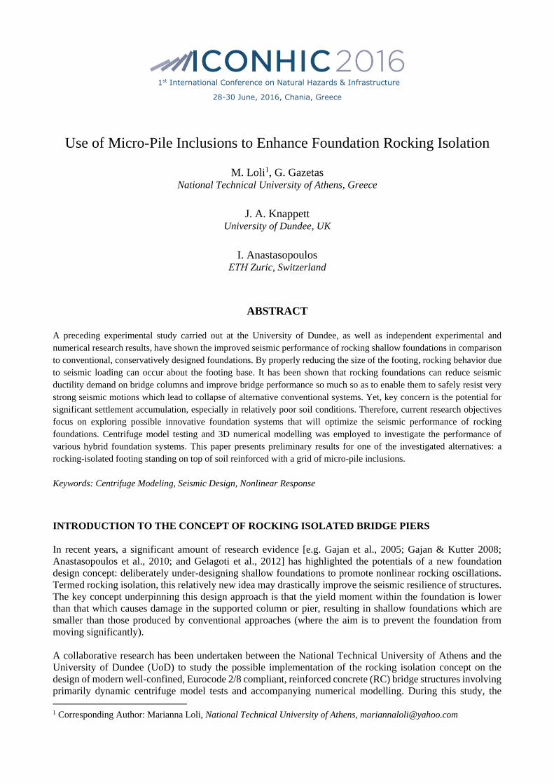
3D dynamic nonlinear finite element (FE) modelling was conducted using ABAQUS and has proved
particularly useful at different stages of this study, namely (1) in the design of the centrifuge experiments; (2)
in the retrospective analysis of the hybrid foundations response mechanisms and (3) in the parametric
investigation of different key design properties. The employed numerical method has been presented in Loli
[2015] and extensively validated against a plethora of experimental results involving shallow foundations
rocking on complying soil.
Fig. 4 displays the FE mesh used in the analysis of the herein presented hybrid foundation solution. The deck
and the footing were simulated using 8-noded hexahedral continuum elements, attributed the elastic properties
of steel and aluminium respectively. The same element type, incorporating nonlinear material response
according to the relationships presented in Anastasopoulos et al. [2011], was used to model the sand layer.
The mesh snapshot highlights the geometry of the micro-pile grid and it should be noted that the micropiles
were simulated using 3D elastic beam elements assigned the geometric and elastic stiffness properties of the
steel section used in the centrifuge tests. Yet, although the surface of the model micro-piles was quite smooth,
the numerical analysis assumed fully bonded conditions in the soil – pile interface (an assumption which may
have an important effect on the results, as will be shown in the following). By contrast, appropriate interface
elements were utilized to realistically simulate the frictional and uplifting properties of the interface between
the footing and the supporting soil.
Figure 4. 3D FE model of the prototype bridge pier rocking upon the micro-pile reinforced soil.
PRESENTATION OF RESULTS
In the following presentation of results all quantities are shown in prototype scale.
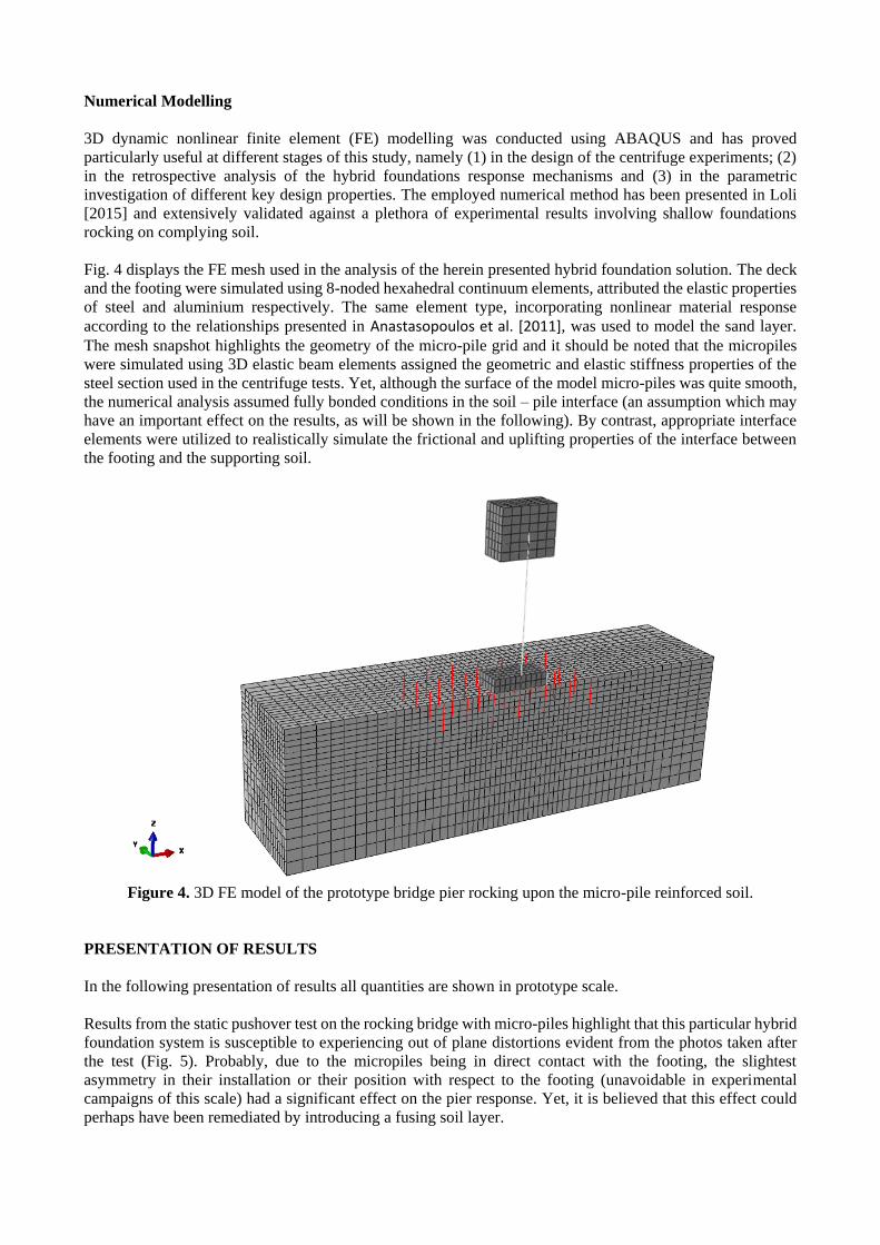
Results from the static pushover test on the rocking bridge with micro-piles highlight that this particular hybrid
foundation system is susceptible to experiencing out of plane distortions evident from the photos taken after
the test (Fig. 5). Probably, due to the micropiles being in direct contact with the footing, the slightest
asymmetry in their installation or their position with respect to the footing (unavoidable in experimental
campaigns of this scale) had a significant effect on the pier response. Yet, it is believed that this effect could
perhaps have been remediated by introducing a fusing soil layer.
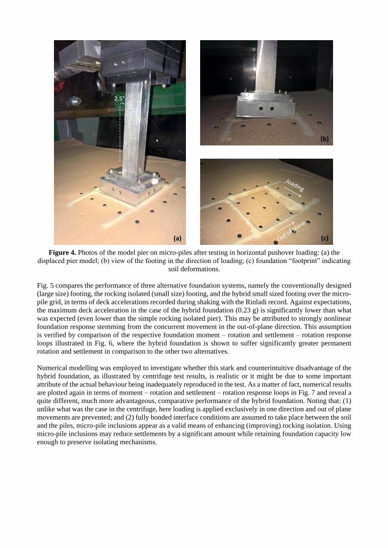
Figure 4. Photos of the model pier on micro-piles after testing in horizontal pushover loading: (a) the
displaced pier model; (b) view of the footing in the direction of loading; (c) foundation “footprint” indicating
soil deformations.
Fig. 5 compares the performance of three alternative foundation systems, namely the conventionally designed
(large size) footing, the rocking isolated (small size) footing, and the hybrid small sized footing over the micro-
pile grid, in terms of deck accelerations recorded during shaking with the Rinladi record. Against expectations,
the maximum deck acceleration in the case of the hybrid foundation (0.23 g) is significantly lower than what
was expected (even lower than the simple rocking isolated pier). This may be attributed to strongly nonlinear
foundation response stemming from the concurrent movement in the out-of-plane direction. This assumption
is verified by comparison of the respective foundation moment – rotation and settlement – rotation response
loops illustrated in Fig. 6, where the hybrid foundation is shown to suffer significantly greater permanent
rotation and settlement in comparison to the other two alternatives.
Numerical modelling was employed to investigate whether this stark and counterintuitive disadvantage of the
hybrid foundation, as illustrated by centrifuge test results, is realistic or it might be due to some important
attribute of the actual behaviour being inadequately reproduced in the test. As a matter of fact, numerical results
are plotted again in terms of moment – rotation and settlement – rotation response loops in Fig. 7 and reveal a
quite different, much more advantageous, comparative performance of the hybrid foundation. Noting that: (1)
unlike what was the case in the centrifuge, here loading is applied exclusively in one direction and out of plane
movements are prevented; and (2) fully bonded interface conditions are assumed to take place between the soil
and the piles, micro-pile inclusions appear as a valid means of enhancing (improving) rocking isolation. Using
micro-pile inclusions may reduce settlements by a significant amount while retaining foundation capacity low
enough to preserve isolating mechanisms.
2.5°
(a)
(b)
(c)

Figure 5. Comparison of acceleration time-history sequences recorded during shaking with the Rinaldi
motion at the: (a) deck of conventional pier (B = 7.5 m); (b) deck of rocking-isolated pier (B = 4 m); and (c)
deck of the rocking pier supported on micro-piles.
Figure 6. Comparison of foundation Μ‒θ and w‒θ hysteretic response during shaking with the entire seismic
sequence, namely the Rinaldi (black line), Aegion (grey line) and L’Aquila (grey line): (a) conventional pier
(B = 7.5 m); (b) rocking-isolated pier (B = 4 m); and (c) rocking pier supported on micro-piles. In each plot,
the two theoretical static curves for two footing sizes are superimposed on the dynamic loops.
-0.4
-0.2
0
0.2
0.4
a :
g
-0.4
-0.2
0
0.2
0.4a
: g
-0.4
-0.2
0
0.2
0.4
a :
g
0 5 10 15
-0.8
-0.4
0
0.4
0.8
a :
g
t : sect : sec
α : g
Table
Free Field
(a)
(b)
(c)
(d)
0.41 g
0.28 g
0.23 g
CONVENTIONAL
ROCKING FOOTING
ROCKING ON MICROPILES
EXCITATION
-0.4
-0.2
0
0.2
0.4
a :
g
-0.4
-0.2
0
0.2
0.4
a :
g
-0.4
-0.2
0
0.2
0.4a
: g
0 5 10 15
-0.8
-0.4
0
0.4
0.8
a :
g
t : sect : sec
α : g
Table
Free Field
(a)
(b)
(c)
(d)
0.41 g
0.28 g
0.23 g
CONVENTIONAL
ROCKING FOOTING
ROCKING ON MICROPILES
EXCITATION
M : MNm
w : cm
CONVENTIONAL (B = 7.5 m) ROCKING (B = 4 m) MICROPILES
Rinaldi Aegion L’Aquila
Earthquake Sequence
θ : deg
(a) (b) (c) -20
-10
0
10
20
M :
MN
m
-2 0 2-30
-20
-10
0
w :
cm
: deg-2 0 2
: deg-2 0 2
: deg
28 cm
21 cm
7.6 cm
Figure 7. Comparison of numerically computed foundation Μ‒θ and w‒θ hysteretic response during shaking
with a Ricker pulse (PGA = 0.6, fE = 1 Hz) for the rocking isolated and the hybrid foundation.
CONCLUSIONS
The paper highlights the importance of adequately modelling key aspects of foundation response in order to
acquire valid results in soil – structure – interaction problems. It studies the comparative performance of a
bridge pier on a rocking footing upon soil with micro-pile inclusions both experimentally and numerically,
employing centrifuge model testing and 3D FE modelling, and highlights the profound importance of
realistically reproducing interface behavior. Furthermore, the unavoidable out of plane distortions occurring
in the centrifuge tests, appear to significantly jeopardize the results for this specific problem. This problem
could be significantly remediated with the introduction of a shallow layer of dense sand between the piles and
the footing.
REFERENCES
Al-Defae A. H., and Knappett J. A. (2014) “Stiffness matching of model reinforced concrete for centrifuge modelling of
soil-structure interaction,” Proc. 8th International Conference on Physical Modelling in Geotechnics, ICPMG ’14,
Perth, Australia, 14-17 January: 1067-1072.
-5000
-2500
0
2500
5000
-2 -1 0 1 2
-5000
-2500
0
2500
5000
-2 -1 0 1 2
θ : deg
M : kNm
θ : deg
-0.1
-0.08
-0.06
-0.04
-0.02
0
0.02
-2 -1 0 1 2w : m
-0.1
-0.08
-0.06
-0.04
-0.02
0
0.02
-2 -1 0 1 2

Anastasopoulos I., Gazetas G., Loli M., Apostolou M., Gerolymos N. (2010) “Soil failure can be used for seismic
protection of structures,” Bulletin of Earthquake Engineering, 8(2), pp. 309-326.
Anastasopoulos I., Gelagoti F., Kourkoulis R., Gazetas G. (2011) “Simplified Constitutive model for Simulation of Cyclic
Response of Shallow Foundations: Validation against Laboratory Tests,” Journal of Geotechnical and
Geoenvironmental Engineering, ASCE, Ωολ. 137(12), pp. 1154-1168.
Bertalot D. (2012) “Behaviour of shallow foundations on layered soil deposits containing loose saturated sands during
earthquakes,” PhD Thesis, University of Dundee, UK.
Gajan S., Kutter B., Phalen J., Hutchinson T., Martin G. (2005), “Centrifuge modeling of load-deformation behavior of
rocking shallow foundations”, Soil Dynamics and Earthquake Engineering, 25, pp. 773 - 783.
Gajan, S. & Kutter, B.L. (2008), "Capacity, settlement, and energy dissipation of shallow footings subjected to rocking",
Journal of Geotechnical and Geoenvironmental Engineering, ASCE, 134(8), pp. 1129–1141.
Gelagoti, F., Kourkoulis, R., Anastasopoulos, I., and Gazetas, G. (2012), “Rocking Isolation of Frame Structures Founded
on Separate Footings”, Earthquake Engineering & Structural Dynamics, 41(7): 1177-1197.
Knappett J.A., Reid C., Kinmond S., and O’Reilly K. (2011) “Small-scale modelling of reinforced concrete structural
elements for use in a geotechnical centrifuge,” Journal of Structural Engineering, ASCE, 137(7), pp. 1263-1271.
Knappett J.A., Reid C., Skeffington K., O’Reilly K., and Gilhooley P. (2010) “Modelling precast concrete piling for use
in the geotechnical centrifuge,” In Proc. 7th International Conference on Physical Modelling in Geotechnics, ICPMG
’10, Zürich: 141-146.
Kutter B. L. (1995). “Recent Advances in Centrifuge Modeling of Seismic Shaking,” Proceedings of the Third
International Conference on Recent Advances in Geotechnical Earthquake Engineering and Soil Dynamics, Vol.2,
pp. 927-942.
Loli M., Knappett J.A., Brown M.J., Anastasopoulos I., and Gazetas G. (2014) “Centrifuge modeling of rocking–isolated
inelastic RC bridge piers,” Earthquake Engineering & Structural Dynamics, 43(15), pp. 2341-2359.
Loli M. (2015) “Non-linear Seismic Interaction Between Soil and a Slender Structure,” PhD Thesis, National Technical
University of Athens, Greece.
Muir Wood D. (2004) “Geotechnical modelling,” Spon Press, London.
Pecker A. (2005) “Design and Construction of the Foundations of the Rion Antirion Bridge,” Proceedings of the 1st
Greece–Japan Workshop on Seismic Design, Observation, Retrofit of Foundations, Athens, pp.119–130.
Steenfelt J.S., Foged B., and Augustesen A.H. (2014). "Izmit Bay Bridge: Geotechnical challenges and innovative
solutions," Proceedings of ISBSBI Conference, 16-18 October 2014, Athens, Greece.