vehicle level antenna pattern & adas measurement level...©2017 ets -lindgren ©2017 ets...
TRANSCRIPT
©2017 ETS-LINDGREN©2017 ETS-LINDGREN
www.scvemc.org
Vehicle Level Antenna Pattern & ADAS Measurement
PresenterGarth D’Abreu
Director Automotive SolutionsETS-Lindgren
[email protected]+1 512 531 6438

©2017 ETS-LINDGREN 2
Today’s complexity.
©2017 ETS-LINDGREN
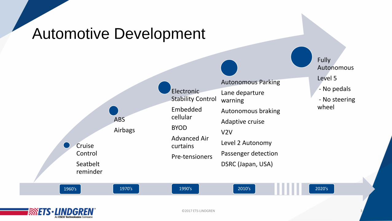
Automotive Development
1960’s 1970’s 1990’s 2010’s 2020’s
3
Cruise ControlSeatbelt reminder
ABSAirbags
Electronic Stability ControlEmbedded cellularBYODAdvanced Air curtainsPre-tensioners
Autonomous ParkingLane departure warningAutonomous brakingAdaptive cruiseV2VLevel 2 AutonomyPassenger detectionDSRC (Japan, USA)
Fully AutonomousLevel 5- No pedals- No steering wheel

©2017 ETS-LINDGREN
Connected Vehicles
4
Vehicle-to-Infrastructure (V2I):Incident detection/ warning Weather/ice detection / warningBroadcast traffic signal timingDynamic re-routing
Vehicle-to-Vehicle (V2V):Electronic hand shakingCollision avoidancePlatooning
Vehicle-to-Cloud (V2C):Broadcast of updatesVehicle status monitoring

©2017 ETS-LINDGREN
Wireless Testing PerformanceTests need to address various frequency ranges:
• FM Radio from 70MHz• HD radio• Cellular from 700MHz to 60GHz (3G, 4G,LTE, 5G)• Satellite from 1.6GHz• WiFi from 2.4/5.8GHz• DSRC 5.9GHz• RADAR 24GHz/ 79GHz
5

©2017 ETS-LINDGREN
What’s In Development – Highly RF Dependent
6
In Development
V2X and Traffic Signal recognition
Lane keeping
Autonomous parking
Pedestrian/object avoidance
Night Vision
Platooning
Sign, Image recognition
Augmented Reality HUD
3D HUD
Image courtesy Texas Instruments

©2017 ETS-LINDGREN
• RADAR used as the primary detector for many ADAS features • ESR RADAR – ACC, FCW, AHC, LDW, EAB, pattern recognition,
RADAR Module
ETS-Lindgren Confidential

©2017 ETS-LINDGREN
RADAR Module Test System
• Used for RADAR module performance and target recognition testing• Measure: Beam width, pattern, transmit power, and sensitivity in the 24GHz,
77GHz and 79GHz bands• Most useful for module level development and production testing• Optional RADAR Simulator integration available
8
Top (or side view)
Qz
Path length

©2017 ETS-LINDGREN
Antenna - Wireless Testing• In the small handset world, Over-The-Air (OTA) testing refers to the radiated performance
of an EUT• This was originally characterized by the conducted device performance with the isolated
antenna pattern• Conducted performance + Antenna characteristic = OTA ?
• This was found to be inadequate and developed into the full OTA tests used today
• In the Auto industry:
+ ?=
+ ?=
©2017 ETS-LINDGREN
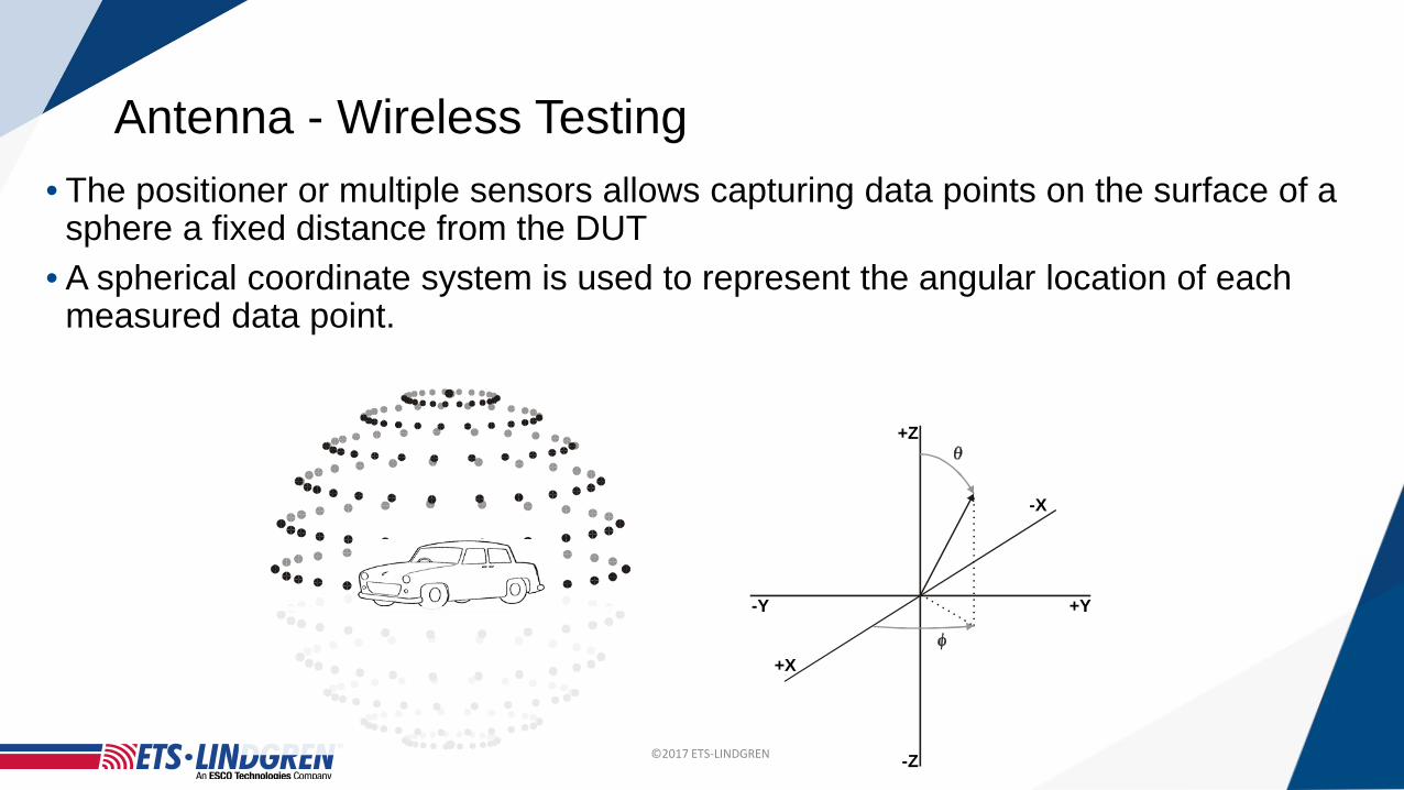
Antenna - Wireless Testing• The positioner or multiple sensors allows capturing data points on the surface of a
sphere a fixed distance from the DUT• A spherical coordinate system is used to represent the angular location of each
measured data point.
+X
+Y-Y
-X
+Z
-Z

©2017 ETS-LINDGREN
Automotive Antennas• Antennas are mounted in various locations inside or outside of the vehicle• These antennas are highly integrated with the automotive body for aesthetic, practical and
performance reasons• And they must perform as an integral part of the vehicle
©2017 ETS-LINDGREN
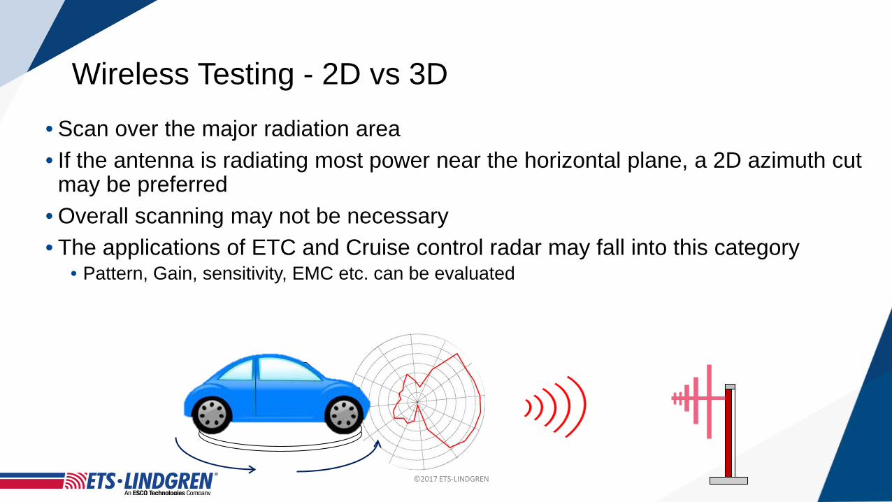
Wireless Testing - 2D vs 3D• Scan over the major radiation area• If the antenna is radiating most power near the horizontal plane, a 2D azimuth cut
may be preferred • Overall scanning may not be necessary• The applications of ETC and Cruise control radar may fall into this category
• Pattern, Gain, sensitivity, EMC etc. can be evaluated

©2017 ETS-LINDGREN
Wireless Testing - 2D vs 3D• If the radio signal propagates more towards the sky - 3D scanning is
preferred• 3D scanning is over the upper hemisphere• Not suitable for long test distance (requires very tall tower and ceiling height )• FF range and Spherical NF scanner can be used

©2017 ETS-LINDGREN
Multi Sensor Array
• Single ring MIMO chamber with multiple sensors (antennas)• The number of sensors relative to DuT position define measurement
angular resolution
Simulated Image
©2017 ETS-LINDGREN
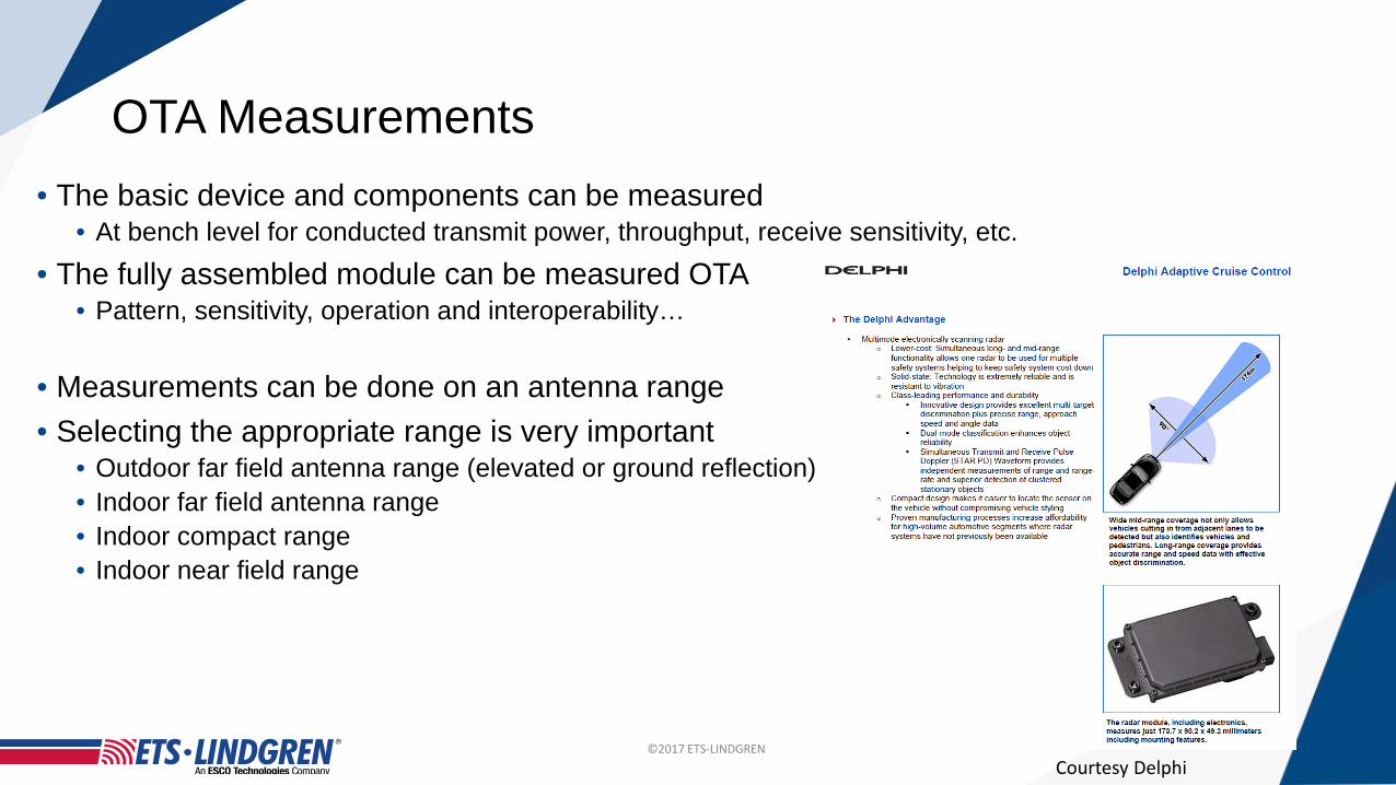
OTA Measurements• The basic device and components can be measured
• At bench level for conducted transmit power, throughput, receive sensitivity, etc.• The fully assembled module can be measured OTA
• Pattern, sensitivity, operation and interoperability…
• Measurements can be done on an antenna range• Selecting the appropriate range is very important
• Outdoor far field antenna range (elevated or ground reflection)• Indoor far field antenna range• Indoor compact range • Indoor near field range
Courtesy Delphi

©2017 ETS-LINDGREN
RADAR Test System• Used for RADAR module operation and target recognition testing using target emulation• Measure beam width, pattern, transmit power, sensitivity, and target discrimination in the
24GHz, 77GHz and 79GHz bands• Approximately 5m x 1.5m x 1.5m test system.• Most useful for module level development and production testing• Relevant Test standard is EN 301091-1
16
Top (or side view)
Qz
Path length
©2017 ETS-LINDGREN
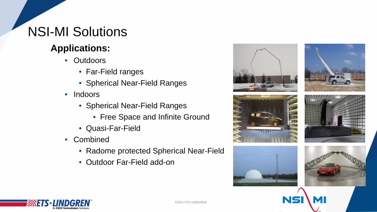
NSI-MI SolutionsApplications:
• Outdoors• Far-Field ranges• Spherical Near-Field Ranges
• Indoors• Spherical Near-Field Ranges
• Free Space and Infinite Ground• Quasi-Far-Field
• Combined• Radome protected Spherical Near-Field• Outdoor Far-Field add-on

©2017 ETS-LINDGREN
Wireless Testing – Hybrid FF Range• Large tapered chamber, designed for dual purposes, APM and EMC
measurement• Antenna Pattern Measurement System
• 2D Long range – taper • 70 MHz to 3 GHz• 40 m test distance
• 3D Short range – roof scanning• 1GHz to 6 GHz• 9 m test distance
©2017 ETS-LINDGREN
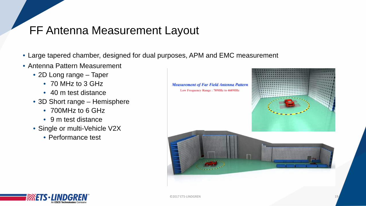
FF Antenna Measurement Layout
• Large tapered chamber, designed for dual purposes, APM and EMC measurement• Antenna Pattern Measurement
• 2D Long range – Taper • 70 MHz to 3 GHz• 40 m test distance
• 3D Short range – Hemisphere• 700MHz to 6 GHz• 9 m test distance
• Single or multi-Vehicle V2X • Performance test
19

©2017 ETS-LINDGREN
Hybrid-Chamber Approach• Semi-Tapered Far-Field Range for Full-Vehicle Antenna, EMC, ADAS Testing
©2017 ETS-LINDGREN
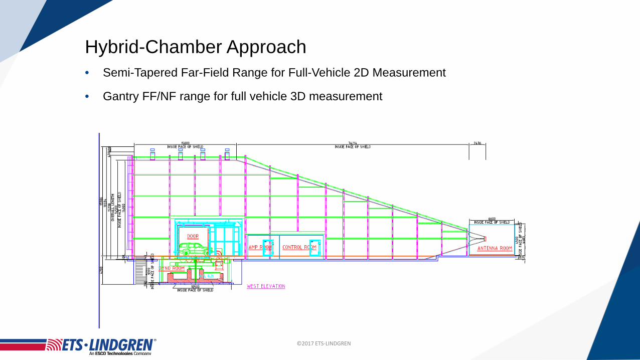
Hybrid-Chamber Approach• Semi-Tapered Far-Field Range for Full-Vehicle 2D Measurement
• Gantry FF/NF range for full vehicle 3D measurement
©2017 ETS-LINDGREN
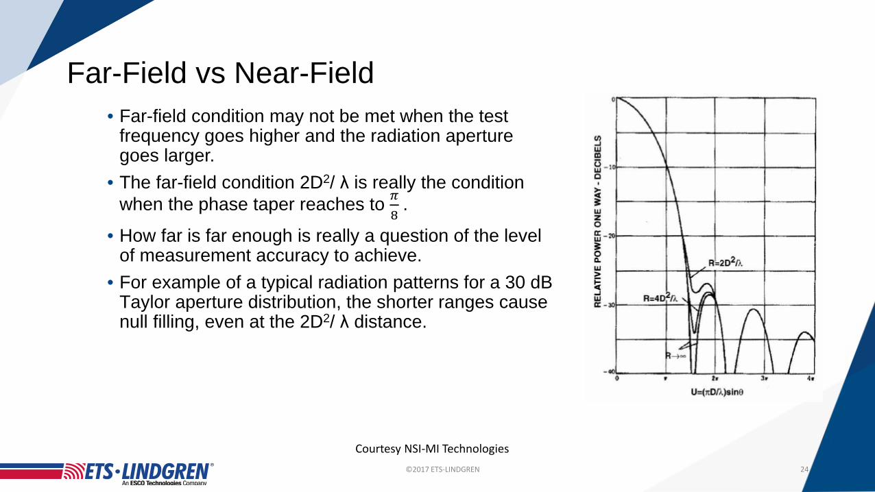
Far-Field vs Near-Field• Far-field condition may not be met when the test
frequency goes higher and the radiation aperture goes larger.
• The far-field condition 2D2/ λ is really the condition when the phase taper reaches to 𝜋𝜋
8.
• How far is far enough is really a question of the level of measurement accuracy to achieve.
• For example of a typical radiation patterns for a 30 dB Taylor aperture distribution, the shorter ranges cause null filling, even at the 2D2/ λ distance.
24
Courtesy NSI-MI Technologies
©2017 ETS-LINDGREN
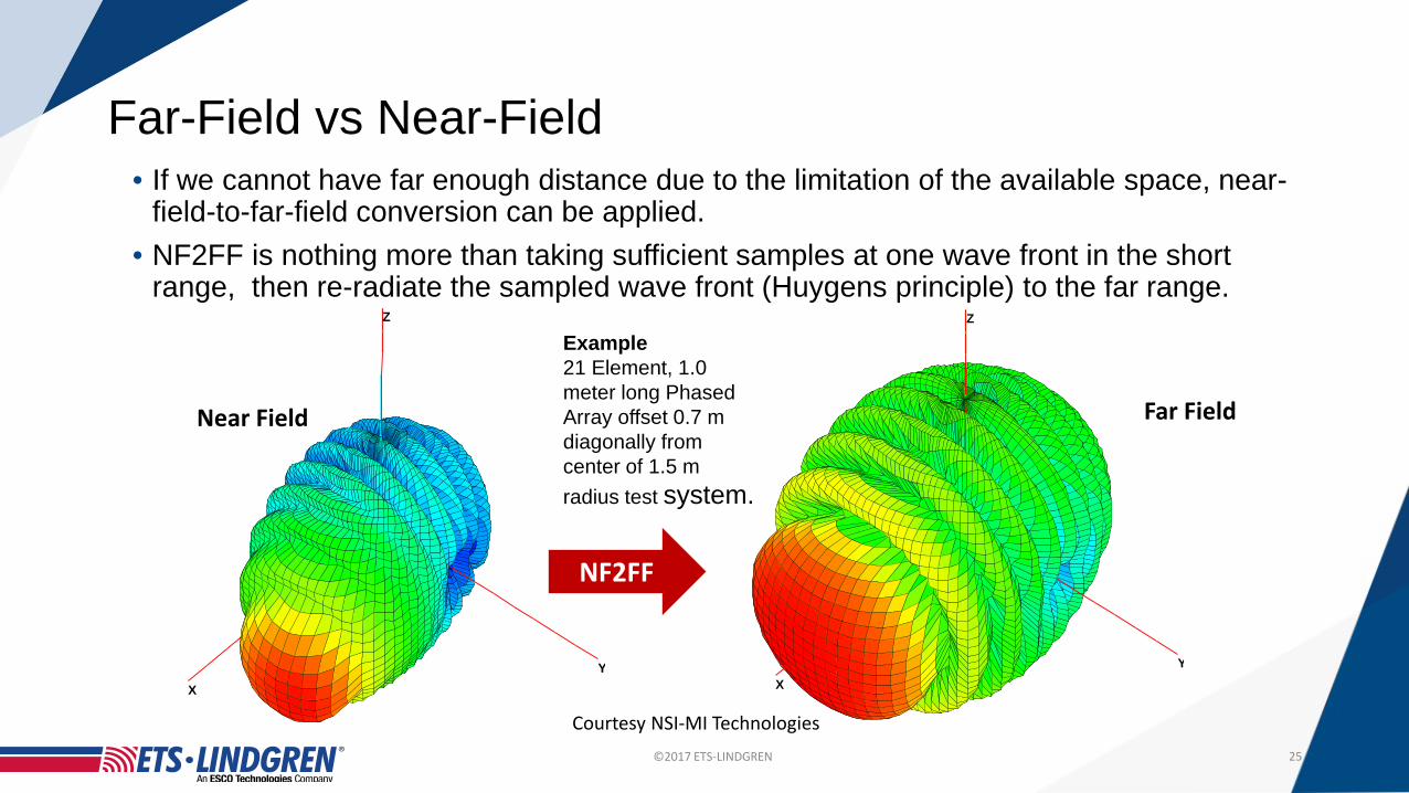
Far-Field vs Near-Field• If we cannot have far enough distance due to the limitation of the available space, near-
field-to-far-field conversion can be applied.• NF2FF is nothing more than taking sufficient samples at one wave front in the short
range, then re-radiate the sampled wave front (Huygens principle) to the far range.
25
YX
Z
YX
Z
Near Field Far Field
Example21 Element, 1.0 meter long Phased Array offset 0.7 m diagonally from center of 1.5 m radius test system.
NF2FF
Courtesy NSI-MI Technologies
©2017 ETS-LINDGREN
26
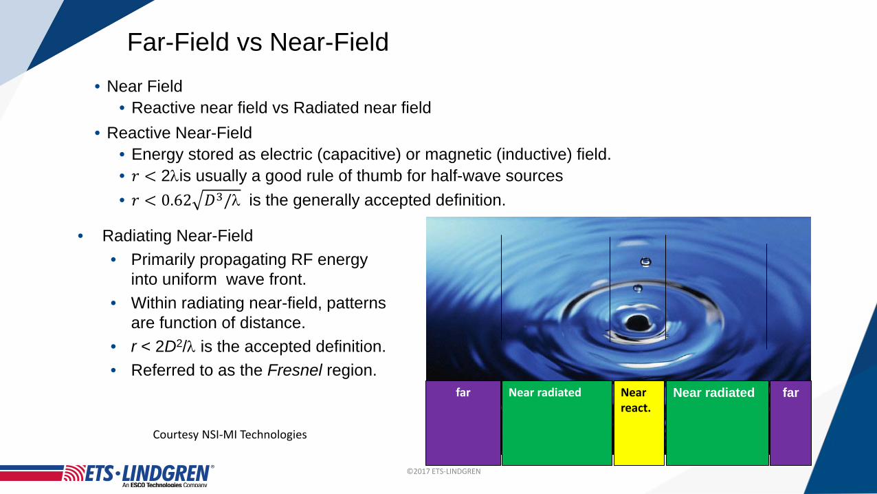
• Near Field• Reactive near field vs Radiated near field
• Reactive Near-Field• Energy stored as electric (capacitive) or magnetic (inductive) field.• 𝑟𝑟 < 2λis usually a good rule of thumb for half-wave sources• 𝑟𝑟 < 0.62 𝐷𝐷3/λ is the generally accepted definition.
Near radiatedNear radiated farfar
Far-Field vs Near-Field
Near react.
• Radiating Near-Field• Primarily propagating RF energy
into uniform wave front.• Within radiating near-field, patterns
are function of distance.• r < 2D2/λ is the accepted definition.• Referred to as the Fresnel region.
Courtesy NSI-MI Technologies

©2017 ETS-LINDGREN
27
• For a NF2FF system, it is important to sample over the major radiation area, which may again be over the upper hemisphere.
• There are several NF scanning methods, for example, cylindrical scanning and spherical scanning.
• Cylindrical scanning is suitable for AUT radiating pattern more confined near the horizontal.
• Spherical scanning is suitable for AUT pattern radiating more towards the sky (upper hemisphere).
Near Field Scanning
Cylindrical Scanning Spherical Scanning

©2017 ETS-LINDGREN
NF- Spherical Sampling Spacing (Steps)• The complete vehicle is the AUT
• Interest : measure the performance of the antenna mounted in the vehicle, not the antenna alone
• Vehicle body and shape affects the antenna performances• Full vehicle size dictates MRE (Maximum Radial Extent of AUT)
• MRE is used to calculate the measurement angular step needed according to Nyquist (1/2 λ)
• Low frequency probe vehicle spacing require large scan radium supported by double-sided gantry
Probe/AUT Distance for Near-field- Good: > 3 λ- Usable: > 2 λ- Minimum : > 1 λ
(very high mutual coupling)
NF probe
AUT Size 6.3x2.3x2 m.
MRE 3.6 m.
FREQ. Nyquist requirementProbe angular step
250 MHz 6 Deg.
1600 MHz 1.25 Deg.
2200 MHz 1 Deg.
2700 MHz 0.8 Deg.
4000 MHz 0.5 Deg.
6000 MHz 0.375 Deg.
MRE
Courtesy NSI-MI Technologies
©2017 ETS-LINDGREN
29
• For a NF2FF system, the chamber absorber performance is less critical.
• The probe to QZ distance is typically 2-3 λ, equivalent to less than 2m.
• Gating can be used to control signals from other reflection boundaries.
• Installation in existing EMC chambers may be feasible without absorber changes.
• Most suitable for measurements at frequencies greater than about 800MHz.
• Not a real time antenna measurement so cannot be used for sensitivity
measurements.
Near Field Scanning

©2017 ETS-LINDGREN
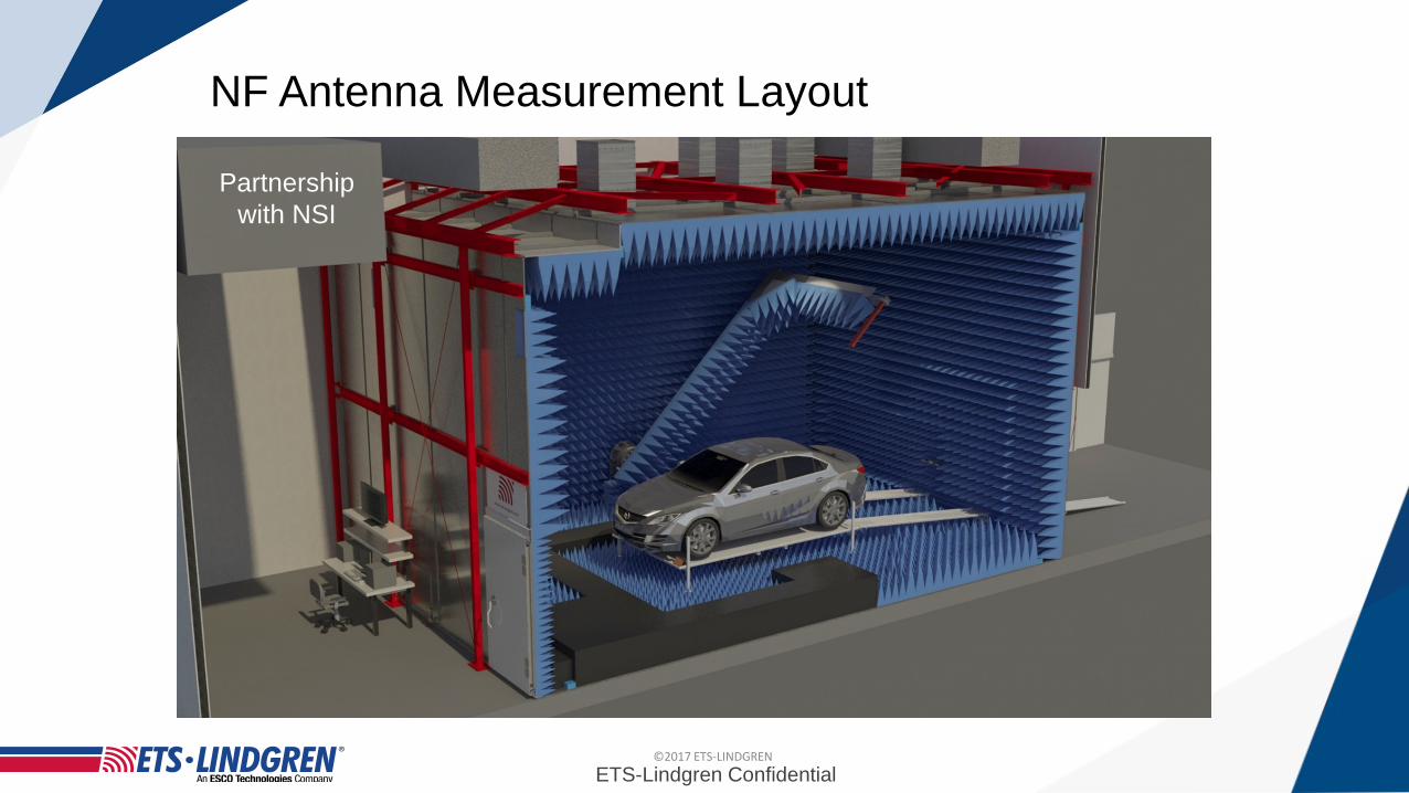
Partnership with NSI-MI
NF Antenna Measurement Layout
©2017 ETS-LINDGREN
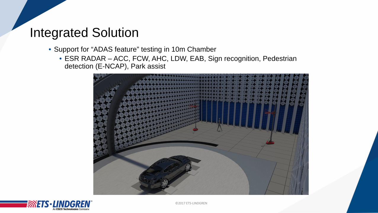
• Support for “ADAS feature” testing in 10m Chamber• ESR RADAR – ACC, FCW, AHC, LDW, EAB, Sign recognition, Pedestrian
detection (E-NCAP), Park assist
Integrated Solution
©2017 ETS-LINDGREN
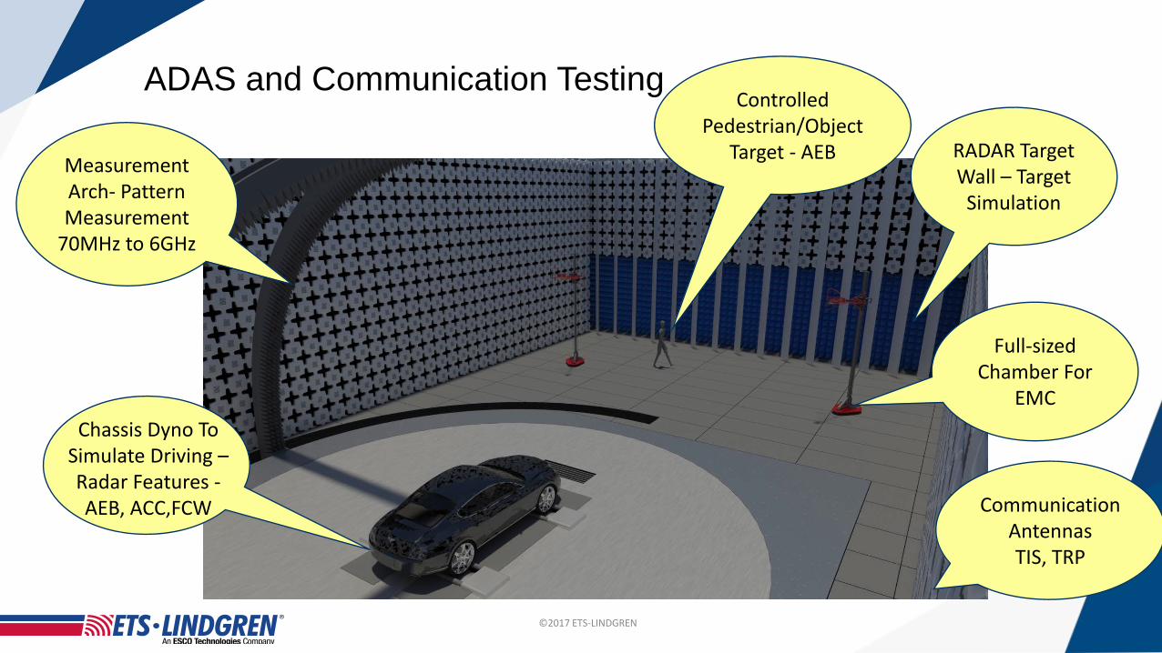
ADAS and Communication Testing
Chassis Dyno To Simulate Driving –Radar Features -AEB, ACC,FCW
Measurement Arch- Pattern Measurement
70MHz to 6GHz
RADAR Target Wall – Target
Simulation
Controlled Pedestrian/Object
Target - AEB
Full-sized Chamber For
EMC
Communication Antennas TIS, TRP

©2017 ETS-LINDGREN
FF Antenna Measurement Layout• Large tapered chamber, designed for dual purposes, APM and EMC measurement• Antenna Pattern Measurement
• 2D Long range – Taper • 70 MHz to 3 GHz• 40 m test distance
• 3D Short range – Hemisphere• 700MHz to 6 GHz• 9 m test distance
• Single or multi-Vehicle V2X • Performance test
33
©2017 ETS-LINDGRENETS-Lindgren Confidential
Partnership with NSI
NF Antenna Measurement Layout

©2017 ETS-LINDGREN
• Support for “ADAS feature” testing in 10m Chamber. • ESR RADAR – ACC, FCW, AHC, LDW, EAB, Sign recognition, Pedestrian
detection (E-NCAP), Park assist.
Full Vehicle Integrated Range
ETS-Lindgren Confidential
©2017 ETS-LINDGREN
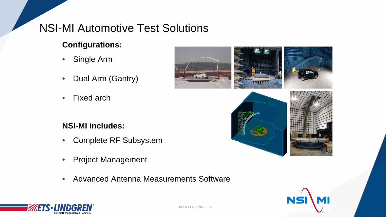
NSI-MI Automotive Test SolutionsConfigurations:
• Single Arm
• Dual Arm (Gantry)
• Fixed arch
NSI-MI includes:
• Complete RF Subsystem
• Project Management
• Advanced Antenna Measurements Software

©2017 ETS-LINDGREN
ETS-Lindgren / NSI Team Capabilities
RF-Shielded Anechoic Chamber

©2017 ETS-LINDGREN
• High Precision Spherical NF • Single arm • 3-Axis: Turntable, gantry arm and polarization• 1.7m vertical arm adjustment• Arm storage capability to allow other type of
testing• 7m. Turntable, 6000 Kg with RJ, SR• Controller • Complete RF Subsystem
• Receiver, Sources, mixers, switches• Probes and reference antennas• Advanced antenna measurements Software
NSI-MI Retractable Design
©2017 ETS-LINDGREN
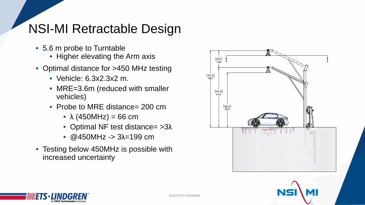
• 5.6 m probe to Turntable• Higher elevating the Arm axis
• Optimal distance for >450 MHz testing• Vehicle: 6.3x2.3x2 m.• MRE=3.6m (reduced with smaller
vehicles)• Probe to MRE distance= 200 cm
• λ (450MHz) = 66 cm• Optimal NF test distance= >3λ• @450MHz -> 3λ=199 cm
• Testing below 450MHz is possible with increased uncertainty
NSI-MI Retractable Design

©2017 ETS-LINDGREN
MI-710CPosition Controller
RANGE
CONTROL ROOM
MI-3003 WORKSTATION
WITH MI-3000 ARENATM
& MI-3046 SNF
SIGNAL CHANNEL
ENET SWITCH
MI t
rigge
r bu
s
MI-350-TATrigger Bus Adapter
Azimuth (TT)
Elevation (Gantry)
Switch control from MI-789
715115 manual switch DC-50GHz
Note: a rotary joint and a polarization stage may be
needed if single linear polarized probes are used
MI-789 Auxiliary Controller
E5072A ENA
Antenna on vehicle
Block Diagram
©2017 ETS-LINDGREN
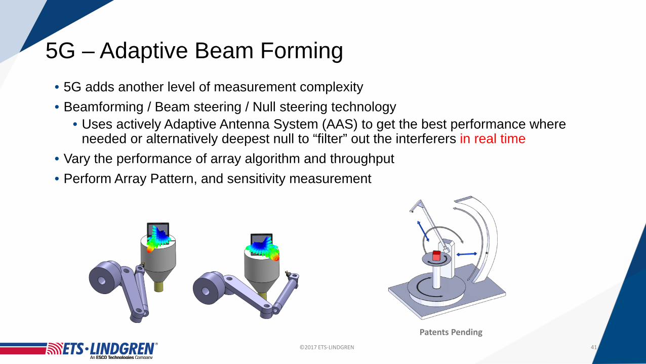
5G – Adaptive Beam Forming• 5G adds another level of measurement complexity• Beamforming / Beam steering / Null steering technology
• Uses actively Adaptive Antenna System (AAS) to get the best performance where needed or alternatively deepest null to “filter” out the interferers in real time
• Vary the performance of array algorithm and throughput• Perform Array Pattern, and sensitivity measurement
41
Patents Pending
©2017 ETS-LINDGREN
Conclusions• The industry is moving rapidly• Already available
• Radio connectivity• Autonomous cruise control, steering, breaking• Navigation• Collision avoidance• Blind spot warning• Integrated infotainment• BYOD support – Apple, Google
• In development• Fully Autonomous capability

©2017 ETS-LINDGREN
• Autonomous Cruise Control• Already available
• Also known as adaptive or radar cruise control• Automatically adjusts vehicle speed to maintain a safe distance from
vehicles ahead• Control based solely on on board sensors • Uses no communication with satellite or roadside infrastructure• 77GHz Auto cruise system available
• Has a forward range of up to 492 ft (150m)• Operates at vehicle speeds ranging from 18.6mph (30kph) to 111mph
(180kph)
Conclusions
©2017 ETS-LINDGREN
Conclusions• New test facilities have already begun to appear designed to support
• EMC• Wireless OTA and interoperability• Antenna measurements
• The demands on absorber design is more important • Interoperability for wireless in EM environment• With optimized chamber performance, and customized layout, the
requirements for the EMC and APM chamber can both be met