vehicle suspension apparatus
TRANSCRIPT

United States Patent [19] Tanaka et a1.
[54] VEHICLE SUSPENSION APPARATUS
[75] Inventors: Tadao Tanaka, Okazaki; Sunao Chikamori, Nagoya; Mitsuhiko Harara, Okazaki; Yasutaka Taniguchi; Masanaga Suzumura, both of Nagoya; Minoru Tatemoto, Okazaki; Naotake Kumagai, Aichi; Hiroki Abe, Okazaki, all of Japan
[11] Patent Number: 4,602,805 [45] Date of Patent: Jul. 29, 1986
4,377,299 3/1983 Fujii .................................. .. 280/708 4,453,725 6/1984 Kuwawa et a1. . 280/708 4,466,625 8/1984 Kondo et al. 280/707 4,468,050 8/1984 Woods et a1. . . . . . . . . . . .. 280/707
4,546,960 10/1985 Abramsetal. ..... .. 280/707
4,564,214 1/1986 Tokunaga et a1. ................ .. 280/708
FOREIGN PATENT DOCUMENTS
53-26021 10/1978 Japan .
[73] Assignee: Mitsubishi Jidosha Kogyo Kabushiki Kaisha, Tokyo, Japan
[21] Appl. No.: 727,376 [22] Filed: Apr. 25, 1985
[30] Foreign Application Priority Data Apr. 25, 1984 [JP] Japan ................................ .. 59-83351 Apr. 27, 1984 [JP] Japan . . . . . . . . .. 59-83865
Apr. 28, 1984 [JP] Japan ........................... .. 59-63113[U] Sep. 29, 1984 [JP] Japan .............................. .. 59-204606 Oct. 9, 1984 [JP] Japan 59-211635 Oct. 9, 1984 [JP] Japan .............................. .. 59-211636
[51] Int. Cl.4 ..................... .. B6OG 11/26; B6OG 17/00 [52] US. Cl. ................................. .. 280/707; 280/6 R;
280/708 [58] Field of Search ............. .. 280/707, 708, 688, 689,
280/703, 711, 6 R; 267/6416
[56] References Cited U.S. PATENT DOCUMENTS
4,326,733 4/1982 Rubalcava ......................... .. 280/708
58-30541 2/1983 Japan. 58-30819 2/1983 Japan.
Primary Examiner-Richard A. Bertsch Attorney, Agent, or Firm—Frishauf, Holtz, Goodman & Woodward
[57] ABSTRACT The front wheel exhaust valves and the rear wheel supply valves are opened for a predetermined period of time when rapid acceleration of the vehicle is detected by the accelerator pedal sensor and the gear position sensor, the absolute value of change in vehicle position and its velocity can be properly controlled. Therefore, comfort and steering stability can be improved as com pared with vehicles mounting of the conventional appa ratus. In addition, since an acceleration state is detected by the gear position sensor as well as the accelerator pedal sensor, rapid acceleration of the vehicle can be accurately detected, thereby preventing unnecessary position control.
25 Claims, 18 Drawing Figures

U.S. Patent Jul. 29, 1986 Sheet 1 of 16 4,602,805

US Patent Jul. 29, 1986 Sheet 2 of 16 4,602,805
F l G.
who zro?wu?mxXXX XXXOQXOOXQOOQOQ w MZQFXMXQXEVWOOOOQQQX XoX XoXX X X X X
m Xu 5 X X X X XOOQX XXXXoXXX X0. m m8 E XXooXXX X XXoX XXXooX X m .Xw é X X XX XooXXXoX XoX XX X0.
m Ea é X XOOX XXOXXXXXXXOOXX
m??aaémw oooooooX XoXXoXXX XX X m .6 E XX XXoXooXXXX XXXooXX m Ea E XOXOXXX XXXoXXoXXXXo. m .XM. i XXXXQXQXXXGXXX XOOXX m .13 i XOXOXX XOXXXXXOX X X,Xo_
2 I._'<n_.xm_ 1
SmOZOFQMIMmXXXXXXXOOXOOXOOQQQQ PNNNT N N N N
‘m. M Lnurwmwwmwwmwmmwnunmwmmwm A M OXDDRTQUMOUMOUMOH W N E RFRFFRRSHRSHRSHRSHR L D 0'
Av“ m N F200 58 E8 wumm P28
PIOEI ljomJ 4.5mm wmOZ .EDOW

US. Patent Jul. 29, 1986 Sheet 3 of 16 4,602,805
F I G. 3A F l G. 35
—o'tf—L i 3 L ‘ _L
F | G. 4‘
INITIALIZE /
HEIGHT CONTROL )5 +
ROLL CONTROL ' IC- I
' V
NOSE DIVE CONTROL r0
! [E SQUAT CONTROL

U.S. Patent 1111.29, 1986 Sheet4ofl6 ‘ 4,602,805
FIG.
(- S T A R T )
v
5 . READ ACCV, ACCA,V,TR »si
[$6 | START CONTROL 1
+ s? l CONTROL FLAG=1 If
DOES ACCA
DECRrPEASE
ISTART RETURN CONTROLI $11
| CONTROL FLAG=O V >
V RETURN

U.S. Patent Jul. 29, 1986 SheétSof 16 4,602,805
. m0 mhqm 62702410
:RNEES $8288

U.S. Patent Jul. 29, 1986
READ ACCV, REV, v ,TR
Sheet 6 Of 16 4,602,805
‘ ,s21
S5 CONTROL FLAG =1
? NO 86 r
START CONTROL | + $7
CONTROL FLAG = 1
NO
7
S28 DOES REv
DECREASE YES 89
CONTROL FLAG=i '? YES SiO
lsTART RETURN CONTROL + 81 i
CONTROL FLAG = o If
i -
( RETURN )

US. Patent Jul. 29, 1986
( START )
8 READ I ACCV, v, TR
82
TR = {ST or 2nd ?
e
| START CONTROL ]
| CONTROL FLAG =i V
' 85
YES CONTROL FLAG= ?
NO [8
DOES a DECREASE ? .
YES 39
CONTROL FLAG=i ? YES 5 f
I§TART RETURN CONTROLI
:7 ( RETURN )
' /
E YES
34 ACCV gvu 7
YES
Sheet 7 of 16 R 4,602,805
831
S38
SH | CONTROL FLAG = olf

U.S. Patent Jul. 29, 1986
FIG.
Sheet 8 of 16 4,602,805
9-- @ READ ACCV, REV, V ,TR
| START CONTROL +
l CONTROL FLAG = 1
Y
DOES REVA D ECREASE
‘ ?
YES 89
‘FLAG = 1
?
YES
/ |
|/ S7
848
SiO r
ISTART RETURN CONTROL] SH
7 < ' RETURN )
L CONTROL FLAG =0 V

Patent Jul. 29, 1986 Sheet9ofl6 ‘4,602,805
FIG. {0
( START )
OPEN VALVES (273) ,(274) (224) , (222)
OPEN VALVES (223) ,(224) A858 (27H ,(272)
____l

U.S. Patent Jul. 29, 1986
FIG. 11
Sheet 10 of 16 4,602,805
( START )
OPEN VALVES (30) , (32)
YES
CLOSE VALVES 362” (30>,(32)
, OPEN VALVES
(223) ,(224) (271), (272)
S61
6 OPEN VALVES (30>,(32)
OPEN VALVES (273) ,(274) (221) ,(222)
Z S56

U.S. Patent Jul. 29, 1986
FIG.
INITIALIZE N57!
TM = O N372 Lg
READ ACCV' M875
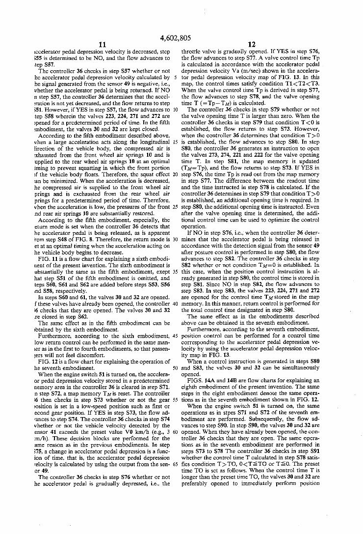
S76
Sheet 11 0f16 4,602,805
i 2
FIND Tp ~57?
4 FIND T=TP—TM N878
s79 T50 T’?
OPEN VALVES OPEN VALVES ‘ 3 (22$),(224) (273),(2?4> T T <27n,(272) (221),(222> M P
Q

- US. Patent Jul. 29,1986. _ Sheet 12 ofl6 4,602,805
F l 6. i3
ACCELERATOR ' VALVE
OPENING VELOCITY CONTROL TIME

US. Patent Jul. 29, 1986 _ Sheetl3 ofl6 4,602,805
-FlG.i4A
'( START )
STW- INITIALIZE
s72~ TM =0
OPEN VALVES ' (30),(32)
S75“ READ ACCV

US. Patent Jul.29, 1986 Sheet 14 ofl6 4,602,805
FIG. {48
S76
NO ACCV>O '.>
s77~ FIND Tp
TM=O S34>TO S78“ FIND
O<TM§TO S9?
CLOSE OPEN OPEN CLOSE VALVES VALVES . VALVES VALVES (3O)1(32) (30%(32) (3O),(32) (30),(32)
3 ( \ I
595 |—} l 896 ‘——l l-——J s93 OPEN VALVES . OPEN VALVES (223),(224) ~883 (273),<274> ~$80 (27!),(272) (22n,(222)

U.S. Patent 1111.29, 1986 SheetlS ofl6 4,602,805
> F I G. {5 ( START )
$51
BSWfPOFF NO YES
s53 NO
YES
354 NO
YES 355
NO YES
sToT
NO
557 3104 NO >
ACCV=VG2 Sm YES to SEC NO 1? , PASSED
OPEN VALVES ? _ YES <273),(274> YES
OPEN VALVES (22i)s(222) (22$),(224) ~$58 RESET (27%) , (272)' T|MER T
1 START S REsET T'MER T 5105 TIMER T “906 x
. I 5103

US. Patent 1111.29, 1986 Sheet 16 0fl6 4,602,805
FIG. {6 ( START )
S51
856 €
OPEN VALVES (273) ,(274) (224) -,(222)
Accvi v02 '2
YES HEIGHT CONTROL 6H2 ROUTINE
OPEN VALVES (223),(2>24) N358 (27i ) ,(272)

4,602,805 1
VEHICLE SUSPENSION APPARATUS
BACKGROUND OF THE INVENTION
The present invention relates to a vehicle suspension apparatus for controlling a change in position of a vehi cle along its longitudinal direction when the vehicle is rapidly accelerated.
In general, a shock absorber having a damping shock absorber and a spring is inserted between the vehicle body and each wheel. Such a suspension apparatus is provided for each of the front and rear wheels. The spring supports the vehicle weight and mainly absorbs a static input, while the shock absorber mainly absorbs a dynamic input. The shock absorber further protects the vehicle body from vibration near a neutral vehicle height position by an external force. However, in this suspension apparatus, when a con
tinuous load acts on the rear wheels as the vehicle is rapidly accelerated, the rear portion of the vehicle body is moved downward while the front portion thereof is moved upward. When acceleration is decreased, the front portion is moved downward while the rear por tion is moved upward, thereby discomforting the driver and passengers and degrading driving stability.
In view of problem, another conventional shock ab sorber with a damping force switching mechanism is known. When the vehicle is rapidly accelerated, the damping force of the shock absorber is increased to decrease a change in vehicle position.
In the above shock absorber, a speed of change in vehicle position can be decreased upon rapid accelera tion of the vehicle, even if the damping force of the shock absorber is increased. However, the absolute value of the change in vehicle position cannot be de creased if an acceleration state is kept for a long period of time, thus failing to provide a satisfactory effect.
SUMMARY OF THE INVENTION
It is an object of the present invention to provide a vehicle suspension apparatus wherein a change in a vehicle position during rapid acceleration can be prop erly controlled to greatly improve steering stability and riding comfort. According to the present invention, there is provided
a vehicle suspension apparatus comprising: front and rear wheel suspension units arranged at wheel positions and having ?uid spring chambers, respectively; ?uid supply means for supplying a ?uid to the ?uid spring chambers in the front and rear wheel suspension units, respectively, through front and rear wheel fluid supply valves; fluid exhaust means for exhausting the ?uid from the ?uid spring chambers in the front and rear wheel suspension units, respectively, through front and rear wheel ?uid exhaust valves; position control means for controlling the front and rear wheel ?uid supply valves and the front and rear wheel ?uid exhaust valves; an accelerator pedal sensor for detecting a state of an accelerator pedal of a vehicle engine and supplying a detection signal to the position control means; and a gear position sensor for detecting a gear change position of a reduction gear of a vehicle and supplying a detec tion signal to the position control means, wherein the position control means opens the front wheel ?uid ex haust valves and the rear wheel ?uid supply valves for a predetermined period of time when a rapid accelera
l0
15
25
30
45
50
55
65
2 tion of the vehicle is detected by the accelerator pedal sensor and the gear position sensor. According to the present invention, since the front
wheel exhaust valves and the rear wheel supply valves are opened for a predetermined period of time when rapid acceleration of the vehicle is detected, the abso lute value of change in vehicle position and its velocity can be properly controlled. Therefore, comfort and steering stability can be improved as compared with vehicles mounting of the conventional apparatus. In addition, since an acceleration state is detected by the gear position sensor as well as the accelerator pedal sensor, rapid acceleration of the vehicle can be accu rately detected, thereby preventing unnecessary posi tion control.
BRIEF DESCRIPTION OF THE DRAWINGS
FIG. 1 is a suspension apparatus according to the present invention; FIG. 2 is a table showing the opening/closing states
in the respective modes of the valves shown in FIG. 1; FIG. 3A is a diagram for explaining the ON state of
each valve shown in FIG. 1; FIG. 3B is a diagram for explaining the OFF state of
each valve shown in FIG. 1; FIG. 4 is a ?ow chart for explaining the main control
flow of the apparatus shown in FIG. 1; FIG. 5 is a flow chart for explaining the operation of
a ?rst embodiment of the present invention; FIG. 6 shows an accelerator pedal depression pat
tern; FIG. 7 is a flow chart for explaining the operation of
a second embodiment of the present invention; FIG. 8 is a ?ow chart for explaining the operation of
a third embodiment of the present invention; FIG. 9 is a flow chart for explaining the operation of
a fourth embodiment of the present invention; FIG. 10 is a flow chart for explaining the operation of
a fifth embodiment of the present invention; FIG. 11 is a ?ow chart for explaining the operation of
a sixth embodiment of the present invention; FIG. 12 is a ?ow chart for explaining the operation of
a seventh embodiment of the present invention; FIG. 13 is a table showing the accelerator pedal de
pression velocity map; FIGS. 14A and 14B are ?ow charts for explaining the
operation of an eighth embodiment of the present inven tlon; FIG. 15 is a ?ow chart for explaining the operation of
a ninth embodiment of the present invention; and FIG. 16 is a ?ow chart for explaining the operation of
a tenth embodiment of the present invention.
DETAILED DESCRIPTION OF THE PREFERRED EMBODIMENTS
The present invention will be described in detail with reference to the preferred embodiments in conjunction with the accompanying drawings. FIG. 1 shows the overall con?guration of a suspen
sion apparatus according to the present invention. Ref erence numeral S FR denotes a front right wheel suspen sion unit; SFL, a front left wheel suspension unit; SRR, a rear right wheel suspension unit; and SRL, a rear left wheel suspension unit. The units SFR, SFL, SRR and SRL have an identical structure and are exemplifeid by the unit SRL. The unit SRL comprises an air spring 10 consisting of a main air spring chamber 11 and an auxil iary air spring chamber 12, a shock absorber 13 and a

4,602,805 3
oil spring (not shown) used as an auxiliary spring. The hock absorber 13 provides a damping force, which is witched between hard and soft by a pneumatic switch nit (actuator) 14. The switch unit 14 opens and closes passage 133 formed in a piston 132 of the shock ab orber 13 by turning a control rod 131 about an axis nereof. In this way, the area of the passage communi ating two chambers de?ned in the shock absorber 13 y the piston 132 is controlled to switch the damping Jrce of the shock absorber 13 between hard and soft. Leference numeral 134 designates a passage formed in he piston 132, through which passage the two cham ers in the shock absorber 13 are communicated with ach other at all time. Reference numeral 15 denotes a ellows which de?nes the main air spring chamber. The nit 14 controls cornmunication/noncommunication etween the chambers 11 and 12, thereby selecting the ard or soft damping mode. The unit 14 is controlled by controller 36 having a microcomputer. Reference numeral 16 denotes an air cleaner. Air
eceived through the cleaner 16 is supplied to a drier 18 rlrough an atmospheric air sealing solenoid valve 17. lir dried by the drier 18 is compressed by a compressor 9 and stored in a reserve tank 21 through a check valve 0. Reference numeral 191 denotes a compressor relay which is controlled by the controller 36. The tank 21 is connected to the main and auxiliary air
pring chambers 11 and 12 in the units SRL to SFL hrough an air intake pipe 23 having air supply solenoid alves 221 to 224 respectively corresponding to the ront and rear wheel suspension units. The chambers 11 nd 12 in the units SRL and SRR are coupled to each ther through a communicating pipe 25 having a com iunicating solenoid valve 241. The chambers 11 and 12 1 the units SFL and SFR are coupled to each other hrough a communicating pipe 26 having a communi ating solenoid valve 242. The compressed air in the hambers 11 and 12 in the units SRL to SFL is exhausted hrough an exhaust pipe 28 with exhaust solenoid valves 71 to 274, a check valve 29, the drier 18, the valve 17 nd the cleaner 16. A pipe 31 having an air intake channel selection sole
.oid valve 30 is arranged in parallel with the pipe 23. Vhen the valve 30 is closed, the compressed air is sup llied from the tank 21 to the respective suspension units hrough only a small-diameter path 310. However, vhen the valve 30 is opened, the compressed air is upplied from the tank 21 to the respective suspension .nits through the path 310 and the large-diameter path 1. A pipe 33 having an exhaust channel selection sole .oid valve 32 is arranged in parallel with the pipe 28. Vhen the valve 32 is closed, the compressed air is ex lausted from the respective suspension units to the drier 8 through a small-diameter path 330. However, when he valve 32 is opened, the compressed air is exhausted hrough the path 33a and the large-diameter path 33. A hard/soft selection solenoid valve 34 is inserted
IetWeen the pipe 23 and the unit 14. The valve 34 is ontrolled in response to a signal from the controller 36. 1 pressure of the tank 21 is detected by a pressure witch 35. A detection signal from the switch 35 is upplied to the controller 36. Reference numeral 37 lenotes a pressure sensor for detecting internal pres ures of the chambers 11 and 12 of the rear suspension [nits SRL and SRR. A detection signal from the sensor "7 is supplied to the controller 36. Reference numeral 38F denotes a front vehicle height
ensor mounted between a front right lower arm 39 and
5
25
40
45
50
65
4 the vehicle body to detect a vehicle height at the front portion of the body. Reference numeral 38R denotes a rear vehicle height sensor mounted between a rear left lateral rod 40 and the vehicle body to detect a vehicle height at the rear portion of the body. Vehicle height signals from the sensors 38F and 38R are supplied to the controller 36. Each of these sensors 38F and 38R com prises an IC element and a magnet, one of which is mounted on the wheel side and the other of which is mounted on the body side so as to detect the distance between the current level and a normal, high or low vehicle height level. The vehicle height sensors can be of another type, e.g., a photointerruptor type.
Reference numeral 41 denotes a vehicle velocity sensor for detecting a vehicle velocity; 42, a steering state sensor for detecting a steering angle and a steering angular velocity of a steering wheel 43; and 44, an ac celeration sensor for detecting back-and-forth, right and-left and vertical acceleration. The sensor 44 can be of a type wherein a weight is suspended and a shielding plate interlocked with the weight shields light from a light-emitting diode so as to prevent light from reaching a photodiode when no acceleration acts, and an acceler ation is detected when the weight is inclined or moved so as to cause light from the light-emitting diode to reach the photodiode. Detection signals from the sen sors 41, 42 and 44 are supplied to the controller 36.
Reference numeral 45 denotes a vehicle height selec tion switch (HSW) for setting a target vehicle height to a high vehicle height (HIGH), a low vehicle height (LOW) or an automatic vehicle height (AUTO). Refer ence numeral 46 denotes a position control selection switch (RSW) for controlling position control so as to decrease rolling of the vehicle. Reference numeral 47 denotes a hydraulic sensor (OSW) for detecting a hy draulic pressure of engine lubricant; 48, a brake sensor (BSW) for detecting a depression angle of a brake pedal; 49, an accelerator pedal sensor (ACSW) for detecting a depression state of the accelerator pedal; 50, an engine speed sensor (RVSW) for detecting an engine speed; 51, an engine switch (ENSW) such as an ignition switch for starting the engine; and 52, a gear position sensor (TRSW) for detecting a gear position of a transmission. Output signals from the switches 45, 46 and 51 and detection signals from the sensors 47, 48, 49 and 50 are supplied to the controller 36. The valves 17, 221 to 224, 271 to 274, 30 and 34 com
prise normally closed valves, respectively; and the valves 241 and 242 comprise normally open valves, respectively. The controller 36 compares the target vehicle heights
set by the switch 45 with the vehicle heights detected by the sensors 38F and 38R, and controls the respective solenoid valves so that the actual vehicle heights coin cide with the target vehicle heights, respectively, thereby performing vehicle height control. The position control function can be performed as
follows. The controller 36 detects a change in vehicle position and its direction in accordance with the outputs from the corresponding sensors and controls the corre sponding solenoid valves so as to cancel the change in vehicle position. When vehicle height control described above is to be
performed, the valves 30 and 32 are closed to slowly change the vehicle height so as to eliminate discomfort to the driver and passengers. When position control described above is to be performed, the valves 30 and 32