ver 4.0.0. 개정내용 2016(v1.1) release notesadmin.midasuser.com/uploadfiles2/74/soilworks...
TRANSCRIPT
1 / 21
SoilWorks SoilWorks 2016(v1.1) Release Notes
Ver 4.0.0. 개정내용
Copyright ⓒ 1989~2014. MIDAS Information Technology Co., Ltd. ALL RIGHTS RESERVED.
2016(v1.1) Release Notes
2 / 21
SoilWorks SoilWorks 2016(v1.1) Release Notes SoilWorks SoilWorks 2016(v1.1) Release Notes Enhancement
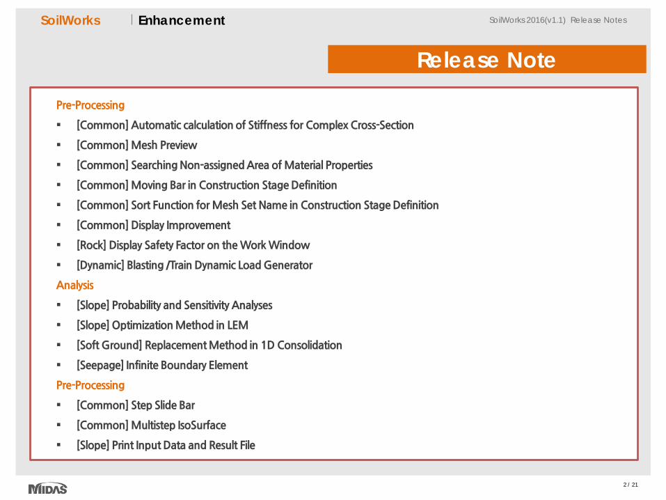
Release Note
Pre-Processing
[Common] Automatic calculation of Stiffness for Complex Cross-Section
[Common] Mesh Preview
[Common] Searching Non-assigned Area of Material Properties
[Common] Moving Bar in Construction Stage Definition
[Common] Sort Function for Mesh Set Name in Construction Stage Definition
[Common] Display Improvement
[Rock] Display Safety Factor on the Work Window
[Dynamic] Blasting /Train Dynamic Load Generator
Analysis
[Slope] Probability and Sensitivity Analyses
[Slope] Optimization Method in LEM
[Soft Ground] Replacement Method in 1D Consolidation
[Seepage] Infinite Boundary Element
Pre-Processing
[Common] Step Slide Bar
[Common] Multistep IsoSurface
[Slope] Print Input Data and Result File
3 / 21
SoilWorks SoilWorks 2016(v1.1) Release Notes SoilWorks SoilWorks 2016(v1.1) Release Notes Enhancement
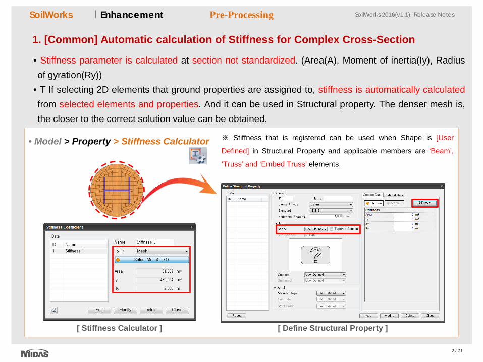
1. [Common] Automatic calculation of Stiffness for Complex Cross-Section
• Stiffness parameter is calculated at section not standardized. (Area(A), Moment of inertia(Iy), Radius of gyration(Ry))
• T If selecting 2D elements that ground properties are assigned to, stiffness is automatically calculated from selected elements and properties. And it can be used in Structural property. The denser mesh is, the closer to the correct solution value can be obtained.
• Model > Property > Stiffness Calculator
Pre-Processing
※ Stiffness that is registered can be used when Shape is [User
Defined] in Structural Property and applicable members are ‘Beam’,
‘Truss’ and ‘Embed Truss’ elements.
[ Stiffness Calculator ] [ Define Structural Property ]
4 / 21
SoilWorks SoilWorks 2016(v1.1) Release Notes SoilWorks SoilWorks 2016(v1.1) Release Notes Enhancement
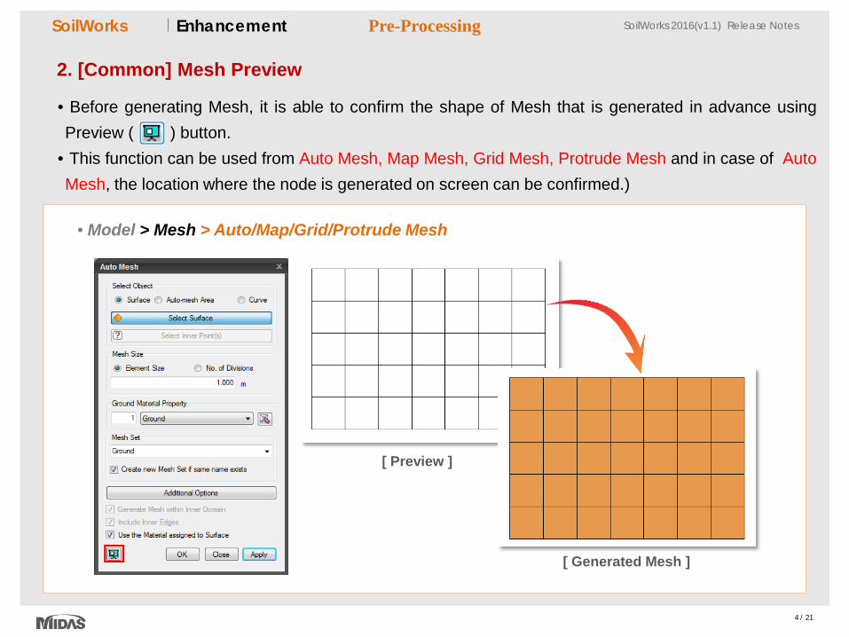
2. [Common] Mesh Preview
• Before generating Mesh, it is able to confirm the shape of Mesh that is generated in advance using Preview ( ) button.
• This function can be used from Auto Mesh, Map Mesh, Grid Mesh, Protrude Mesh and in case of Auto Mesh, the location where the node is generated on screen can be confirmed.)
• Model > Mesh > Auto/Map/Grid/Protrude Mesh
Pre-Processing
[ Preview ]
[ Generated Mesh ]
5 / 21
SoilWorks SoilWorks 2016(v1.1) Release Notes SoilWorks SoilWorks 2016(v1.1) Release Notes Enhancement
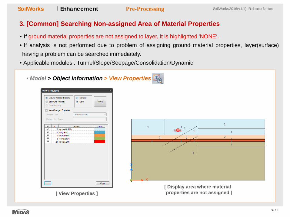
3. [Common] Searching Non-assigned Area of Material Properties
• If ground material properties are not assigned to layer, it is highlighted 'NONE‘. • If analysis is not performed due to problem of assigning ground material properties, layer(surface) having a problem can be searched immediately.
• Applicable modules : Tunnel/Slope/Seepage/Consolidation/Dynamic
• Model > Object Information > View Properties
[ View Properties ] [ Display area where material properties are not assigned ]
Pre-Processing
6 / 21
SoilWorks SoilWorks 2016(v1.1) Release Notes SoilWorks SoilWorks 2016(v1.1) Release Notes Enhancement
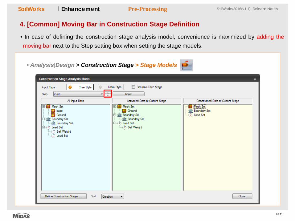
4. [Common] Moving Bar in Construction Stage Definition
• In case of defining the construction stage analysis model, convenience is maximized by adding the moving bar next to the Step setting box when setting the stage models.
• Analysis|Design > Construction Stage > Stage Models
Pre-Processing
7 / 21
SoilWorks SoilWorks 2016(v1.1) Release Notes SoilWorks SoilWorks 2016(v1.1) Release Notes Enhancement
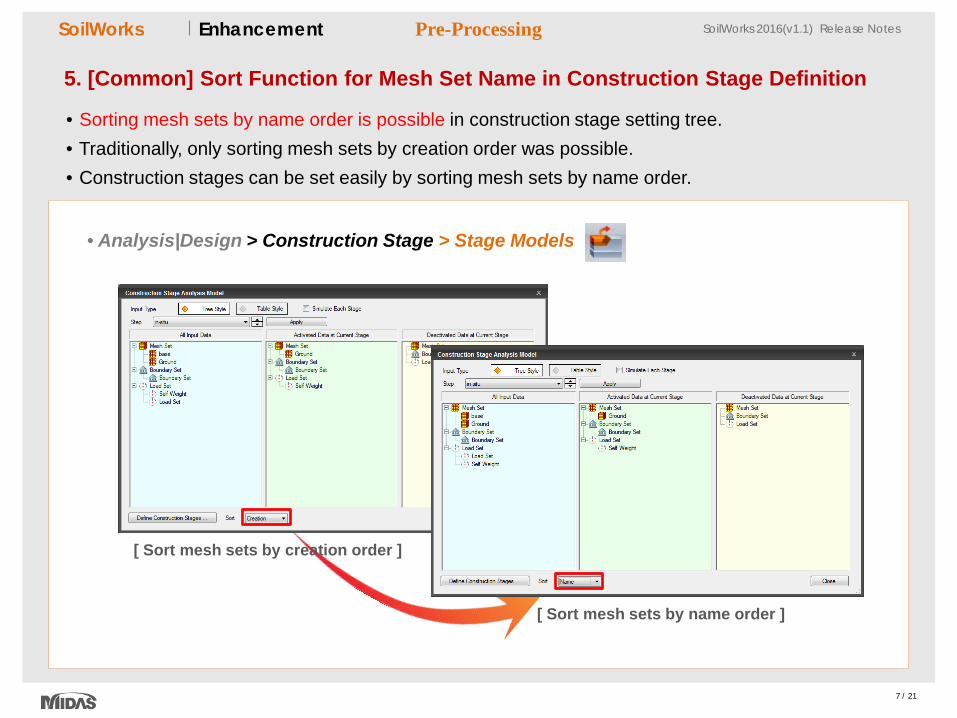
5. [Common] Sort Function for Mesh Set Name in Construction Stage Definition
• Sorting mesh sets by name order is possible in construction stage setting tree. • Traditionally, only sorting mesh sets by creation order was possible. • Construction stages can be set easily by sorting mesh sets by name order.
• Analysis|Design > Construction Stage > Stage Models
[ Sort mesh sets by name order ]
[ Sort mesh sets by creation order ]
Pre-Processing
8 / 21
SoilWorks SoilWorks 2016(v1.1) Release Notes SoilWorks SoilWorks 2016(v1.1) Release Notes Enhancement
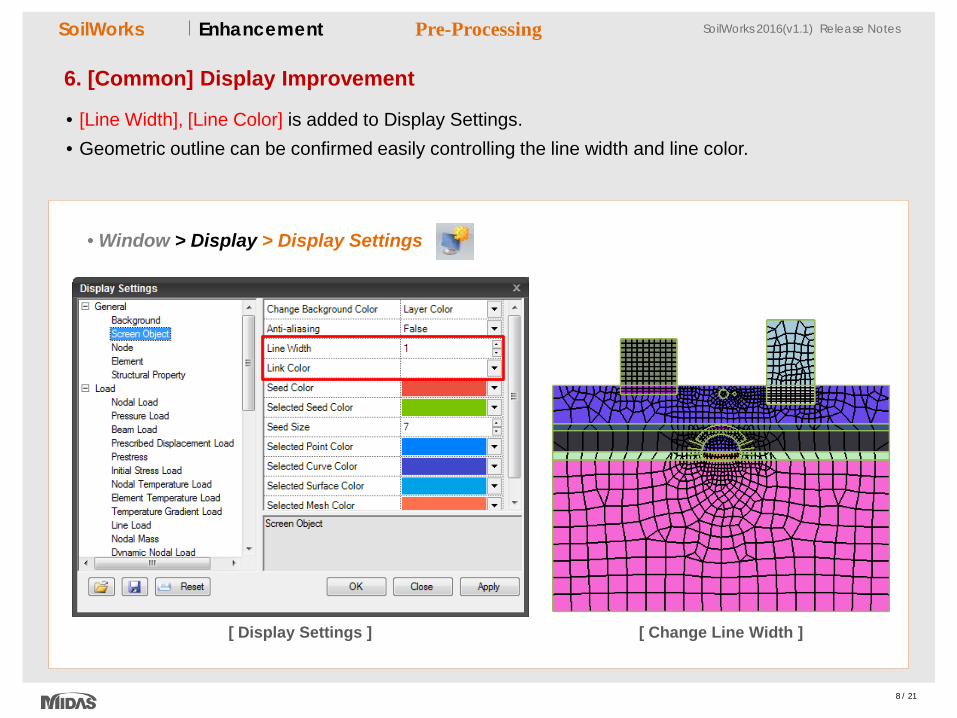
6. [Common] Display Improvement
• [Line Width], [Line Color] is added to Display Settings. • Geometric outline can be confirmed easily controlling the line width and line color.
• Window > Display > Display Settings
Pre-Processing
[ Change Line Width ] [ Display Settings ]
9 / 21
SoilWorks SoilWorks 2016(v1.1) Release Notes SoilWorks SoilWorks 2016(v1.1) Release Notes Enhancement
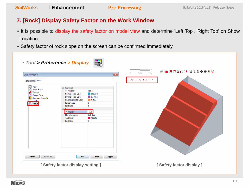
7. [Rock] Display Safety Factor on the Work Window
• It is possible to display the safety factor on model view and determine 'Left Top', 'Right Top' on Show Location.
• Safety factor of rock slope on the screen can be confirmed immediately.
• Tool > Preference > Display
[ Safety factor display setting ] [ Safety factor display ]
Pre-Processing
10 / 21
SoilWorks SoilWorks 2016(v1.1) Release Notes SoilWorks SoilWorks 2016(v1.1) Release Notes Enhancement
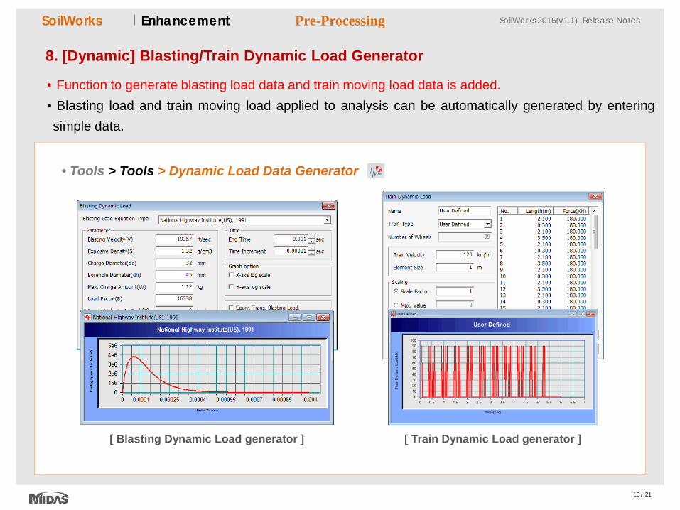
8. [Dynamic] Blasting/Train Dynamic Load Generator
• Function to generate blasting load data and train moving load data is added. • Blasting load and train moving load applied to analysis can be automatically generated by entering simple data.
• Tools > Tools > Dynamic Load Data Generator
[ Blasting Dynamic Load generator ] [ Train Dynamic Load generator ]
Pre-Processing
11 / 21
SoilWorks SoilWorks 2016(v1.1) Release Notes SoilWorks SoilWorks 2016(v1.1) Release Notes Enhancement
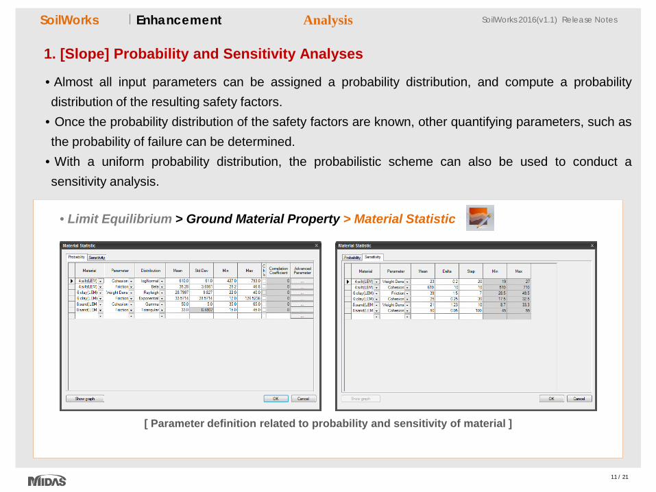
1. [Slope] Probability and Sensitivity Analyses
• Almost all input parameters can be assigned a probability distribution, and compute a probability distribution of the resulting safety factors.
• Once the probability distribution of the safety factors are known, other quantifying parameters, such as the probability of failure can be determined.
• With a uniform probability distribution, the probabilistic scheme can also be used to conduct a sensitivity analysis.
Analysis
• Limit Equilibrium > Ground Material Property > Material Statistic
[ Parameter definition related to probability and sensitivity of material ]
12 / 21
SoilWorks SoilWorks 2016(v1.1) Release Notes SoilWorks SoilWorks 2016(v1.1) Release Notes Enhancement
1. [Slope] Probability and Sensitivity Analyses
Analysis
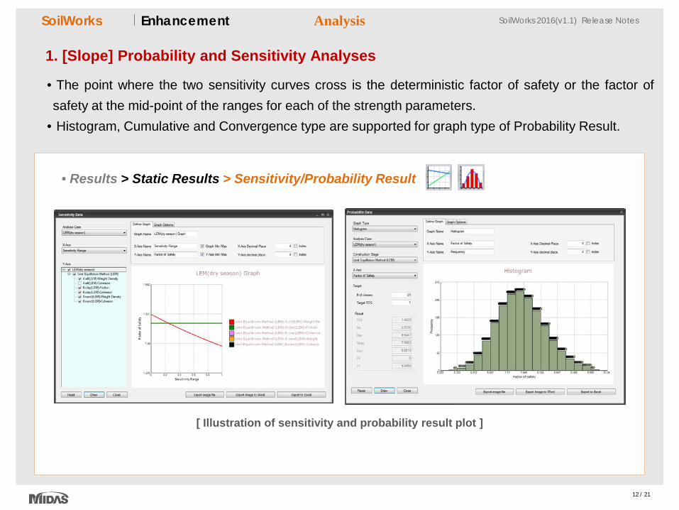
[ Illustration of sensitivity and probability result plot ]
• The point where the two sensitivity curves cross is the deterministic factor of safety or the factor of safety at the mid-point of the ranges for each of the strength parameters.
• Histogram, Cumulative and Convergence type are supported for graph type of Probability Result.
• Results > Static Results > Sensitivity/Probability Result
13 / 21
SoilWorks SoilWorks 2016(v1.1) Release Notes SoilWorks SoilWorks 2016(v1.1) Release Notes Enhancement
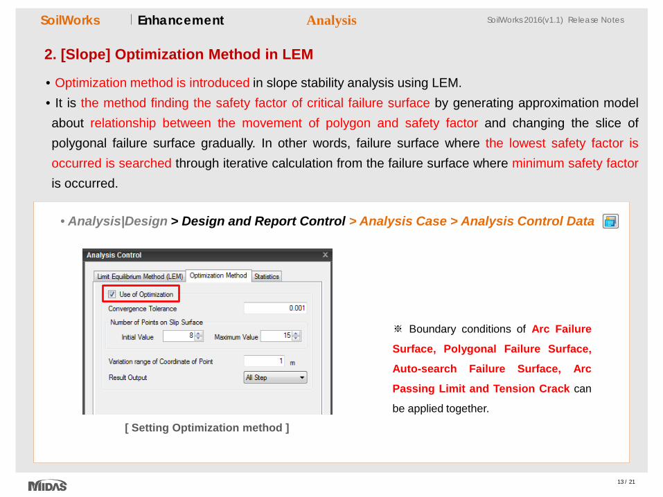
2. [Slope] Optimization Method in LEM
• Optimization method is introduced in slope stability analysis using LEM. • It is the method finding the safety factor of critical failure surface by generating approximation model about relationship between the movement of polygon and safety factor and changing the slice of polygonal failure surface gradually. In other words, failure surface where the lowest safety factor is occurred is searched through iterative calculation from the failure surface where minimum safety factor is occurred.
Analysis
• Analysis|Design > Design and Report Control > Analysis Case > Analysis Control Data
※ Boundary conditions of Arc Failure
Surface, Polygonal Failure Surface,
Auto-search Failure Surface, Arc
Passing Limit and Tension Crack can
be applied together.
[ Setting Optimization method ]
14 / 21
SoilWorks SoilWorks 2016(v1.1) Release Notes SoilWorks SoilWorks 2016(v1.1) Release Notes Enhancement
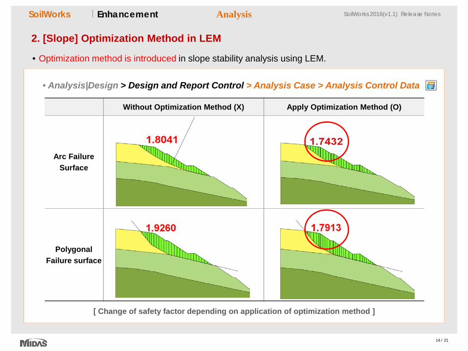
2. [Slope] Optimization Method in LEM
• Optimization method is introduced in slope stability analysis using LEM.
Analysis
• Analysis|Design > Design and Report Control > Analysis Case > Analysis Control Data
[ Change of safety factor depending on application of optimization method ]
Without Optimization Method (X) Apply Optimization Method (O)
Arc Failure Surface
Polygonal Failure surface
15 / 21
SoilWorks SoilWorks 2016(v1.1) Release Notes SoilWorks SoilWorks 2016(v1.1) Release Notes Enhancement
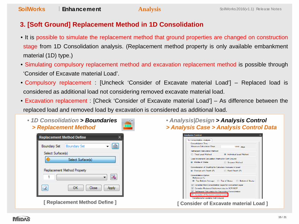
3. [Soft Ground] Replacement Method in 1D Consolidation
• It is possible to simulate the replacement method that ground properties are changed on construction stage from 1D Consolidation analysis. (Replacement method property is only available embankment material (1D) type.)
• Simulating compulsory replacement method and excavation replacement method is possible through ‘Consider of Excavate material Load’.
• Compulsory replacement : [Uncheck ‘Consider of Excavate material Load’] – Replaced load is considered as additional load not considering removed excavate material load.
• Excavation replacement : [Check ‘Consider of Excavate material Load’] – As difference between the replaced load and removed load by excavation is considered as additional load.
Analysis
• 1D Consolidation > Boundaries > Replacement Method
[ Replacement Method Define ] [ Consider of Excavate material Load ]
• Analysis|Design > Analysis Control > Analysis Case > Analysis Control Data
16 / 21
SoilWorks SoilWorks 2016(v1.1) Release Notes SoilWorks SoilWorks 2016(v1.1) Release Notes Enhancement
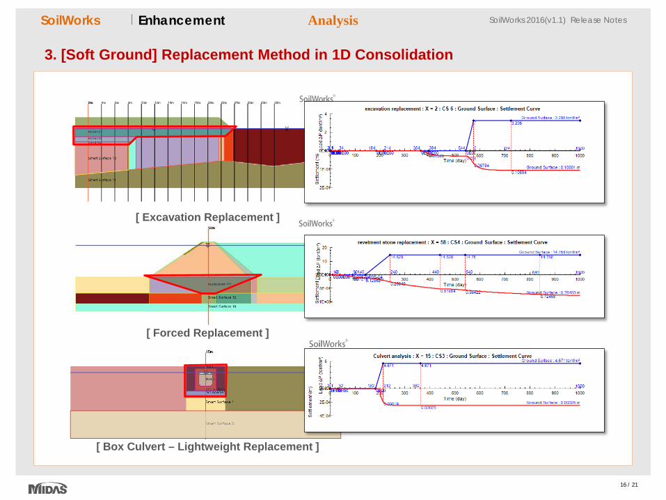
3. [Soft Ground] Replacement Method in 1D Consolidation
Analysis
[ Excavation Replacement ]
[ Forced Replacement ]
[ Box Culvert – Lightweight Replacement ]
17 / 21
SoilWorks SoilWorks 2016(v1.1) Release Notes SoilWorks SoilWorks 2016(v1.1) Release Notes Enhancement
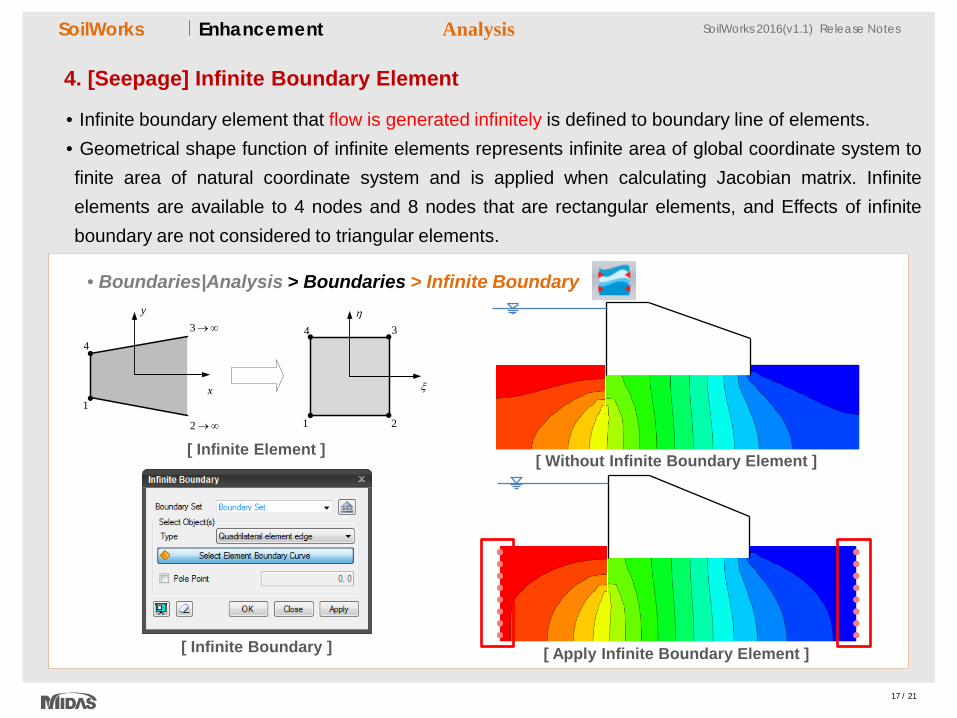
4. [Seepage] Infinite Boundary Element
• Infinite boundary element that flow is generated infinitely is defined to boundary line of elements. • Geometrical shape function of infinite elements represents infinite area of global coordinate system to finite area of natural coordinate system and is applied when calculating Jacobian matrix. Infinite elements are available to 4 nodes and 8 nodes that are rectangular elements, and Effects of infinite boundary are not considered to triangular elements.
Analysis
• Boundaries|Analysis > Boundaries > Infinite Boundary
[ Infinite Boundary ]
1
2 →∞
3→∞
4
1 2
34
x
y
ξ
η
[ Infinite Element ] [ Without Infinite Boundary Element ]
[ Apply Infinite Boundary Element ]
18 / 21
SoilWorks SoilWorks 2016(v1.1) Release Notes SoilWorks SoilWorks 2016(v1.1) Release Notes Enhancement
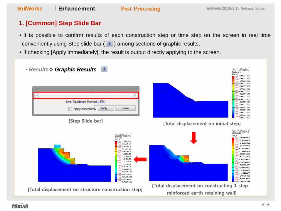
1. [Common] Step Slide Bar
• It is possible to confirm results of each construction step or time step on the screen in real time conveniently using Step slide bar ( ) among sections of graphic results.
• If checking [Apply immediately], the result is output directly applying to the screen.
• Results > Graphic Results
Post-Processing
[Step Slide bar] [Total displacement on initial step]
[Total displacement on constructing 1 step
reinforced earth retaining wall] [Total displacement on structure construction step]
19 / 21
SoilWorks SoilWorks 2016(v1.1) Release Notes SoilWorks SoilWorks 2016(v1.1) Release Notes Enhancement
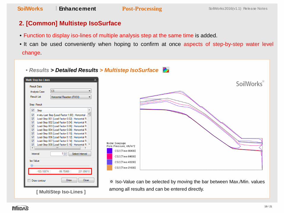
2. [Common] Multistep IsoSurface
• Function to display iso-lines of multiple analysis step at the same time is added. • It can be used conveniently when hoping to confirm at once aspects of step-by-step water level change.
• Results > Detailed Results > Multistep IsoSurface
Post-Processing
[ MultiStep Iso-Lines ]
※ Iso-Value can be selected by moving the bar between Max./Min. values among all results and can be entered directly.
20 / 21
SoilWorks SoilWorks 2016(v1.1) Release Notes SoilWorks SoilWorks 2016(v1.1) Release Notes Enhancement
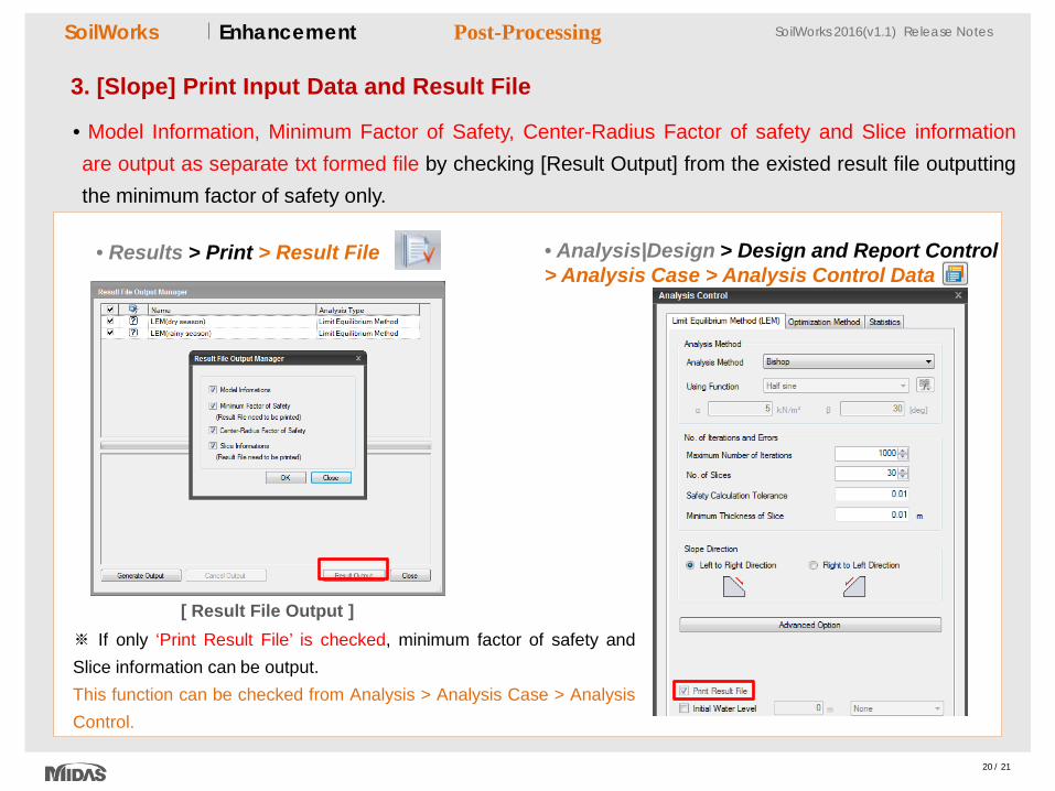
3. [Slope] Print Input Data and Result File
• Model Information, Minimum Factor of Safety, Center-Radius Factor of safety and Slice information are output as separate txt formed file by checking [Result Output] from the existed result file outputting the minimum factor of safety only.
Post-Processing
• Results > Print > Result File • Analysis|Design > Design and Report Control > Analysis Case > Analysis Control Data
[ Result File Output ] ※ If only ‘Print Result File’ is checked, minimum factor of safety and Slice information can be output. This function can be checked from Analysis > Analysis Case > Analysis Control.
21 / 21
SoilWorks SoilWorks 2016(v1.1) Release Notes SoilWorks SoilWorks 2016(v1.1) Release Notes Enhancement
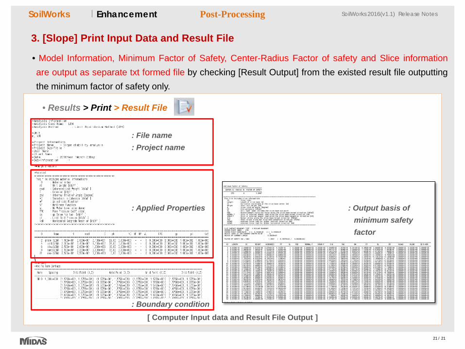
3. [Slope] Print Input Data and Result File
• Model Information, Minimum Factor of Safety, Center-Radius Factor of safety and Slice information are output as separate txt formed file by checking [Result Output] from the existed result file outputting the minimum factor of safety only.
Post-Processing
• Results > Print > Result File
[ Computer Input data and Result File Output ]
: Output basis of minimum safety factor
: Applied Properties
: Boundary condition
: File name : Project name