· web viewoccasionally, it can be difficult getting the computer to communicate to the ip camera...
TRANSCRIPT

Nathan BarnwellFinal Report
Shot Bot
Intelligent Machines Design Laboratory
EEL 4665/5666
Instructors: Dr. A. Antonio ArroyoDr. Eric M. Schwartz
TAs : Ryan StevensTim Martin

Table of Contents1. Abstract ……………………………………………………………………………...……32. Executive Summery……………………………………………………………………….33. Introduction………………………………………………………………………………..34. Integrated System………………………………………………………………………….45. Mobile Platform…………………………………………………………………………...46. Actuation…………………………………………………………………………………..57. Sensors…………………………………………………………………………………….58. Behaviors………………………………………………………………………………….89. Experimental Layout and Results…………………………………………………………810. Conclusion……………………………………………………………………………….1011. Documentation………………………………………………………………………...…1112. Appendices……………………………………………………………………………….12
2

Abstract
Shot Bot navigates through an arena, avoids obstacles that it encounters. Once the enemy colored beacon is located, and then launches a non-lethal shot at the target.
Executive Summary
Shot Bot searches for the enemy colored beacon with its projectile loaded and ready to fire. It navigates around obstacles using infrared proximity sensors, an ultrasonic sensor, and a bump sensor with some redundancy in order to ensure obstacle detection and avoidance. This obstacle avoidance and target searching state continues until the enemy beacon is spotted.
The state is changed to the alignment state once the target is spotted with Shot Bot’s IP camera. During this state, Shot Bot centers itself if the target is on the edges of the image and creeps forward if the target is in the centered. If the target is ever lost during the alignment state, Shot Bot returns to the obstacle avoidance and search state. Once the target is centered and at the bottom of the image, which indicates that the target is within firing range, Shot Bot shoots its projectile at the target.
Shot Bot isolates the beacon showing the enemy’s color using OpenCv and CVblobs. In the image processing code, the color of interest of interest is isolated using a color threshold and the areas of the color of interest are grouped into blobs. The smaller sized blobs are eliminated from consideration since there is a good chance that they could be a reflection or a false target. The center positions of the remaining blobs are then averaged and the average center location is stored, interpreted, and then sent out to Shot Bot using Xbee as a value that it can make sense of.
Introduction
The goal of Shot Bot is to locate and shoot at a specified target while avoiding any obstacles along the way. During a cycle, Shot Bot travels though an arena in search of an illuminated target. It navigates around obstacles until it locates its target, aligns itself, and then fires a non-lethal projectile at the target. Shot Bot integrates a combination of circuitry, logic, mobile platform, motor, servo, and sensor designs in order to carry out the behavioral goals.
3

μP
IR Sensors
Xbee
Bump Sensor
Drive Motors
Shooting Mechanism
(Servo)(servo)
LCD Display
Motor Controller
Servo Controller
LEDs
Shot Bot Integrated SystemUltrasonic Sensor
IP Camera Laptop XbeeRouter
Figure 1 This shows the layout of the Shot Bot integrated system.
Integrated System
Shot Bot is an integrated system that allocates sensors, a microprocessor, controllers, motors, servos, an LCD display, and LEDs as seen in Figure 1. The sensors used for avoiding obstacles communicate with the microprocessor as inputs. These sensors include infrared detectors and an ultrasonic detector that function as proximity sensors and a bump sensor that detects collision. They are arranged in a manner that helps to minimize bind spots and maximize object position awareness. The IP camera captures images from the front of the laptop and sends this data to the laptop, which processes the video, and then the laptop sends information back to the microprocessor using Xbee. The microprocessor outputs to the motor and servo controllers, LCD display, and LEDs based on these inputs. Finally, the controllers output the desired voltage to the motors and servos which create actuation for this system.
Mobile Platform
Shot Bot has a two tier, circular mobile platform constructed from plywood so it will be both strong, easy to construct, and cost effective for this design. The base is a circular shape with cutouts for the wheels inside and centered on the base. This combination decreases obstacle collision while turning, protects the wheels from collision, and increases maneuverability. Additionally, the bottom tier has the motors mounted to it using brackets, the main circuit board, and the battery for powering the robot. Locating all of these components on the bottom tier lowers the center of gravity and increases stability. The top tier has the shooting mechanism and camera mounted on it so there is a minimized obstructed path for tracking and shoots the target.
4

Actuation
The actuation in Shot Bot consists of two drive motors and a servo for controlling the shooting mechanism. The drive motors are from pololu.com (item #1105) and the servo is from sparkfun.com (sku: ROB-09347).
The drive motors are each 12V with a maximum stall torque of 200oz-in and maximum speed of 150 RPM. The motor also has 5A stall so if Shot Bot runs into a wall, the current drawn will not destroy the robot’s circuitry. The characteristics of this motor provide reasonable amount of speed while not being too fast to inhibit the constancy of the Shot Bot’s functions. The torque provides a sufficient amount of torque for moving Shop Bot around the arena. An internal gear ratio of 67:1 was selected so the gearing of the motor is as compact and tailored for this design. Calculations concerning the motors and their ability to satisfy the requirements for Shot Bot can be seen in Appendix A.1 and A.2
The drive motors have the wheels mounted directly to the motor shafts for a direct drive configuration. The motors are mounted next to each other in the center of Shot Bot so if both motors are rotating in opposite directions, the robot will either drive forward or reverse, depending on the electrical current direction. When the motors are rotating in the same direction, the robot will spin clockwise or counter clockwise and will do so on an axis in the center of the robot if identical signal magnitudes are given to the motor controllers. This configuration is beneficial for obstacle avoidance because Shot Bot can change directions in a space confined by its footprint.
A hacked servo will be used as a trigger for the firing mechanism. It operates at 5V and rotates 360° with a maximum speed of 65RPM. It also provides 49 oz-in of stall torque which is sufficient to spin the trigger cam that has to overcome the force of the spring on the firing lever.
Sensors
Shot Bot is equipped with infrared sensors, bump switches, an ultrasonic sensor and an IP camera in order to receive useful information from the surrounding environment.
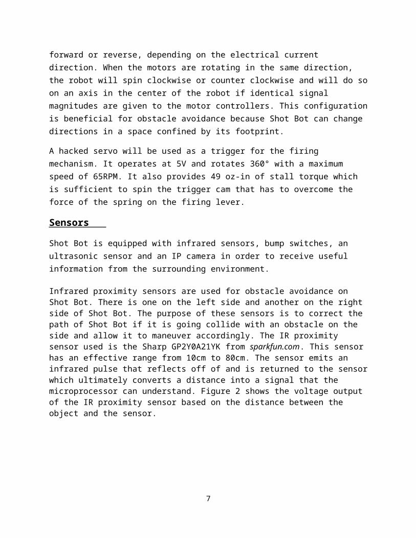
Infrared proximity sensors are used for obstacle avoidance on Shot Bot. There is one on the left side and another on the right side of Shot Bot. The purpose of these sensors is to correct the path of Shot Bot if it is going collide with an obstacle on the side and allow it to maneuver accordingly. The IR proximity sensor used is the Sharp GP2Y0A21YK from sparkfun.com. This sensor has an effective range from 10cm to 80cm. The sensor emits an infrared pulse that reflects off of and is returned to the sensor which ultimately converts a distance into a signal that the microprocessor can understand. Figure 2 shows the voltage output of the IR proximity sensor based on the distance between the object and the sensor.
5

0 5 10 15 20 25 30 350
0.5
1
1.5
2
2.5
3
Infrared Proximity Sensor Output
Left IRRight IR
Distance (in)
Out
put (
V)
Figure 1 This chart shows the distance and voltage output correlation for this IR proximity sensor. This chart data was measured from the right and left IR sensors and the conversions for the voltage can be found in A.3.
A bump sensor will be attached to a bumper so if an obstacle bypasses the IR sensors and ultrasonic sensor, Shot Bot will be aware of its presence. The bump sensor used is a double-throw, single pole switch from pololu.com (item #1403).
The LV-MaxSonar-EZ0 is a 42 kHz ultrasonic sensor that is used on the front of the robot for detecting obstacles. The sensor emits an ultrasonic pulse and the time that it takes for the pulse to return to the sensor is output as an analog voltage. This voltage is sent to the microprocessor and can be interpreted as a distance. It has a beam angle of 70° which is wide enough to cover the front of the robot. The main purpose of this sensor is to avoid any collisions from the front that the infrared sensors may miss. With a range of about 8ft for objects greater than 0.25 in, this sensor will be able to detect objects before they need to be avoided. The ultrasonic sensor used is from sparkfun.com (sku: SEN-08502). Figure 3 shows the voltage output of the ultrasonic sensor based on the distance the object is away from the sensor in inches.
6
0 5 10 15 20 25 30 35 40 450
0.050.1
0.150.2
0.250.3
0.350.4
0.450.5
Ultrasonic Output
Ultrasonic
Distance(in)
Out
put (
V)
Figure 2 This chart shows the distance and voltage output correlation for this Ultrasonic sensor. This chart data was measured for the ultrasonic sensor and the conversions for the voltage can be found in A.3, similarly to the IR sensors.
These infrared proximity sensors, ultrasonic sensors, and the bump sensor work together so Shot Bot can detect and avoid obstacles. If there is an object that is in only in the threshold for the right or left infrared proximity sensors, Shot Bot rotates away from the object until it is back outside of the threshold distance. If an object is detected in the threshold range of the ultrasonic sensor in the front, Shot Bot rotates until the object is out of the way. If the bump senor is pressed, Shot Bot moves away from the object.
The Foscam FI8918W IP camera on Shot Bot is used for tracking the illuminated target. The IP camera communicates with a laptop running OpenCV 2.3 through a wireless router. The program grabs the video data from the IP camera and it isolates the target color from the surrounding environment. Then the software takes all of the blobs of that particular color, excludes blobs smaller that a threshold size, and places rectangles around the blobs that meet the size requirements. These centers of all the blob rectangles are computed and the average position of all the rectangle centers is determined based on their position in the frame. The data is then interpreted by the laptop, and a number corresponding to the particular case is then sent to Shot Bot.
The initial design for Shot Bot actually had a CMU camera instead of an IP Camera. However, after ordering the CMU camera seattlerobotics.com and waiting for 2 weeks, they never collected the money nor shipped the product and could not be contacted. At this point, I decided that I still wanted to have a camera on Shot Bot. Ultimately, the idea of viewing what Shot Bot sees on a laptop screen from a distance outweighed the increased complexly that would accompany this new design and the IP camera replaced that CMU camera.
7

Behaviors
The three main states that Shot Bot operates in are search, obstacle avoidance, and the alignment and shooting states and can be seen in Figure 4.
During the obstacle avoidance/search state, Shot Bot systematically maneuvers until it locates obstacles or the target. When an obstacle is found by one of the IR sensors, ultrasonic sensor, or bump sensor, Shot Bot avoids it by altering its search maneuvering pattern which is the obstacle avoidance state. The alignment state occurs when the target is located by the camera. During this state, Shot Bot will move towards the target very slowly and corrects its course if it ever gets of course, until it is in range of the target. When it gets in range and position of the target, Shot Bot shoots it. If the target is ever lost during any state, it goes back to the obstacle avoidance/search state.
Experimental Layout and Results
Obstacle Avoidance
After testing the infrared proximity sensors on each side of the robot, it was determined that these sensors have a narrow range that created many blind spots on Shot Bot with only two infrared sensors. As a result, the primary obstacle avoidance configuration has a central ultrasonic proximity sensor in the middle since it has a wide and far range of detection. The two infrared sensors are going to be kept on the outsides of the mobile platform so Shot Bot can avoid obstacles on one particular side and correct the direction of Shot Bot if it gradually drifts into an obstacle. Additionally, it was discovered that the effective range for the infrared sensors
8
μP
IP Camera/Laptop
IR Sensors Bump Sensors Ultrasonic
Sensor
Shooting Mechanism
Drive MotorsNo Target Spotted
Target Spotted
Obstacle Avoidance/Search
Alignment
ShootingTarget in Position
Environmental Trigger
Drive Motors
Sensor Input and Processing
μP
μP
OutputState
Figure 4 This is a flow chart demonstrating the behavior of Shot Bot based on environmental triggers and what the outputs will be based on these triggers.
IP Camera/Laptop

is from 5 inches to 30 inches and that critical points in the obstacle avoidance code should account for at least 3 inches of uncertainty since output values tend to vary even at rest.
IP Camera
Setting up the IP camera with OpenCV ended up taking a lot of time and energy. OpenCV itself was challenging to setup, but ultimately investing the resources in it turned out to be a good decision. It is a powerful program that allows the laptop to grab data from the camera and interpret the data. An important discovery during this process was that two different IP cameras may have the same code to function with OpenCV, but the IP address format for grabbing the camera data can. After everything was set up, OpenCV became a very powerful tool.
Occasionally, it can be difficult getting the computer to communicate to the IP camera through the router since the IP address often changes. Once they are communicating, the camera works fantastic. The laptop can control the pan and tilt of the IP camera using the html page interface and I hope to be able to access those commands though OpenCV since it could make searching for the target a much easier task.
Tracking Objects
During testing, it became apparent that lighting conditions seemed to significantly affect the quality, ability, and consistency that the IP camera was able to detect a specific color. To overcome this many steps were taken as precautions to maximize the performance of Shot Bot.
On the target itself, there is a very bright blue light encased in a ping pong ball that is enclosed in a box with a window on only one side. The blue color was determined to be a preferred color to track since most outside obstacles are not the particular shade of blue that I chose. The ping-pong ball enclosure was used to disperse the light that was emitted from the LED so Shot Bot had a larger object to track and the bright light inside was chosen in order to reduce the effect of external light reflecting off of the object. The enclosed box with the window serves two purposes which are to block external light from the beacon and reflect any extra blue light from the beacon.
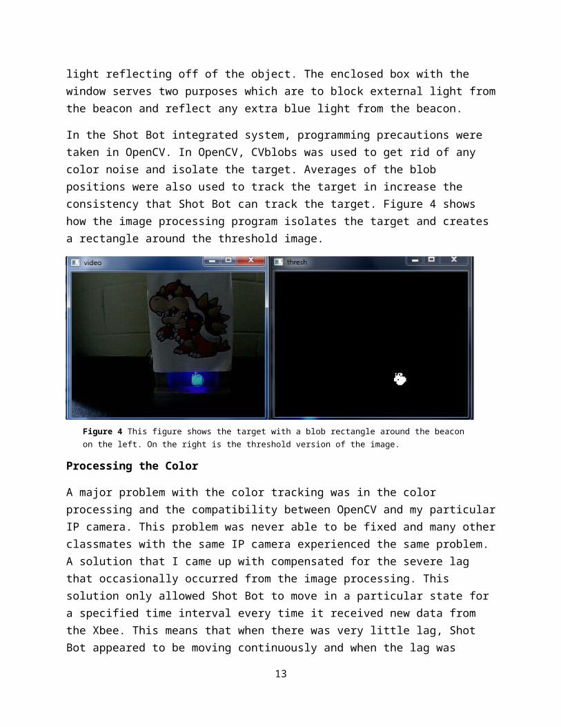
In the Shot Bot integrated system, programming precautions were taken in OpenCV. In OpenCV, CVblobs was used to get rid of any color noise and isolate the target. Averages of the blob positions were also used to track the target in increase the consistency that Shot Bot can track the target. Figure 4 shows how the image processing program isolates the target and creates a rectangle around the threshold image.
9

Processing the Color
A major problem with the color tracking was in the color processing and the compatibility between OpenCV and my particular IP camera. This problem was never able to be fixed and many other classmates with the same IP camera experienced the same problem. A solution that I came up with compensated for the severe lag that occasionally occurred from the image processing. This solution only allowed Shot Bot to move in a particular state for a specified time interval every time it received new data from the Xbee. This means that when there was very little lag, Shot Bot appeared to be moving continuously and when the lag was severe, Shot Bot has jerky movement and even stops in place. This was Shot Bot does not keep moving until it is sure of the environment around it.
Conclusion
Shot Bot was constructed by cutting out and drilling all of the features of the mobile platform by hand which made modifications very easy to make, but at the cost of precision and the visual appeal. Then all of the components, like the motors, wheels, and sensors, were mounted into the desired place. This stage of the creation of Shot Bot did not give me too much trouble since I have some previous assembly experience.
The trickiest mechanical component of Shot Bot was the shooting mechanism that I personally designed and fabricated. My idea of a using a tear drop shaped cam as the trigger worked as I wanted and it minimized the number of moving components for the shooting system. It was very challenging to balance the servo torque and the force from the tension spring since the system seemed to be hyper sensitive to the relative position of all the components. The position of the components also greatly affected the trajectory characteristics of the projectile. After lots of trial and error with different combinations, I was able to get a relatively consistent shot that did not place a large strain on the servo.
10
Figure 4 This figure shows the target with a blob rectangle around the beacon on the left. On the right is the threshold version of the image.

OpenCV gave me a lot of trouble and consumed a huge amount of time that I spent working on Shot Bot. Setting up was probably the worst part about it, but once I got it working, OpenCV became a very powerful image processing tool. It allowed color isolation and helped to exclude false color blobs using CVblobs.
After I had all of the individual components of Shot Bot working, I had to integrate the entire system which presented unanticipated challenges like the occasional lag in the image processing that I compensated for in coding. I also learned that complex obstacle avoidance created more problems than cases were it helped, so the simple solution turned out to be the best. I also had trouble with the Xbee data input was interfering with my servo and it was also solved using coding. Overall, I got the Shot Bot integrated system to work better than I expected considering the challenges that I was faced with.
The major difficulties I had with Shot Bot was in the programming portion since that is the area of the project that I have the least experience in and my limited knowledge of microprocessors also challenged me. Networking with other classmates was helpful because where my knowledge of a particular component was limited, other classmates where more knowledgeable and vice versa. Networking was helpful to both designers and ultimately led to more high quality projects. Additionally, networking allowed me to learn more about robotics than I would have been able to by searching though resources on my own.
If I were to do the project over again, I would try to have the image processing code with OpenCV done much sooner so I would have more time to make the code better and do more things with it like shape or face detection. I would also machine cut the shooting mechanism out of a stronger material like aluminum on a mill so it would be more durable and have more repeatable results. Additionally, I would add a servo controlled loader to the shooter so it could fire many more shots in a controlled manner.
Documentation
http://www.aishack.in/2010/07/tracking-colored-objects-in-opencv/ -Source code for OpenCV color tracking
http://www.technical-recipes.com/2011/tracking-coloured-objects-in-video-using-opencv/ -Source code for OpenCV and CVblobs
https://sites.google.com/site/epiphanydiy/ - Source code created by Tim Martin for the Epiphany DIY board that I used.
11

Appendices
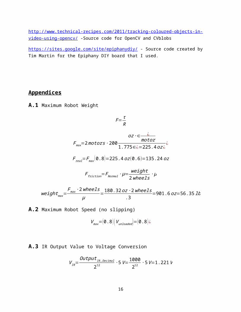
A.1 Maximum Robot Weight
F= τR
Fmax=2 motors ∙200oz ∙∈ ¿
motor1.775∈¿=225.4 oz ¿
¿
F real=Fmax (0.8 )=225.4 oz (0.6)=135.24 oz
F friction=F Normal ∙ μ= weight2wheels
∙ μ
weightmax=Fmax ∙2wheels
μ=180.32 oz ∙ 2wheels
.3=901.6 oz=56.35 lb
A.2 Maximum Robot Speed (no slipping)
V max=(0.8 ) (V unloaded )=(0.8 ) ¿
A.3 IR Output Value to Voltage Conversion
V IR=Output IR, Decimal
212 ∙ 5V =1000212 ∙5V =1.221V
A.4 Robot Code and OpenCV Code
Main Code#include <asf.h>#include <avr/io.h>#include <ctype.h>#include <stdint.h>#include <stdio.h>#include <util/delay.h>#include "motor.h"#include "lcd.h"#include "uart.h"
12
#include "RTC.h"#include "picServo.h"//#include "ATtinyServo.h"#include "ADC.h"#include "sonar.h"
#define DbLedOn() (PORTR.OUTCLR = 0x02) //Turns the debug led on. The led is connected with inverted logic#define DbLedOff() (PORTR.OUTSET = 0x02) //Turns the debug led off. The led is connected with inverted logic#define DbLedToggle() (PORTR.OUTTGL = 0x02) //Toggles the debug led off. The led is connected with inverted logic
int speed=1; //robot speed
ObsticalAvoidance(void);Alignment(void);Shoot(void);volatile uint8_t ObjectPosition = 0;int rando=0;int k=0;int terrain=0;//hard floor//int terrain=10;//carpetint newxbee=0;int shotok=0;
int main (void){
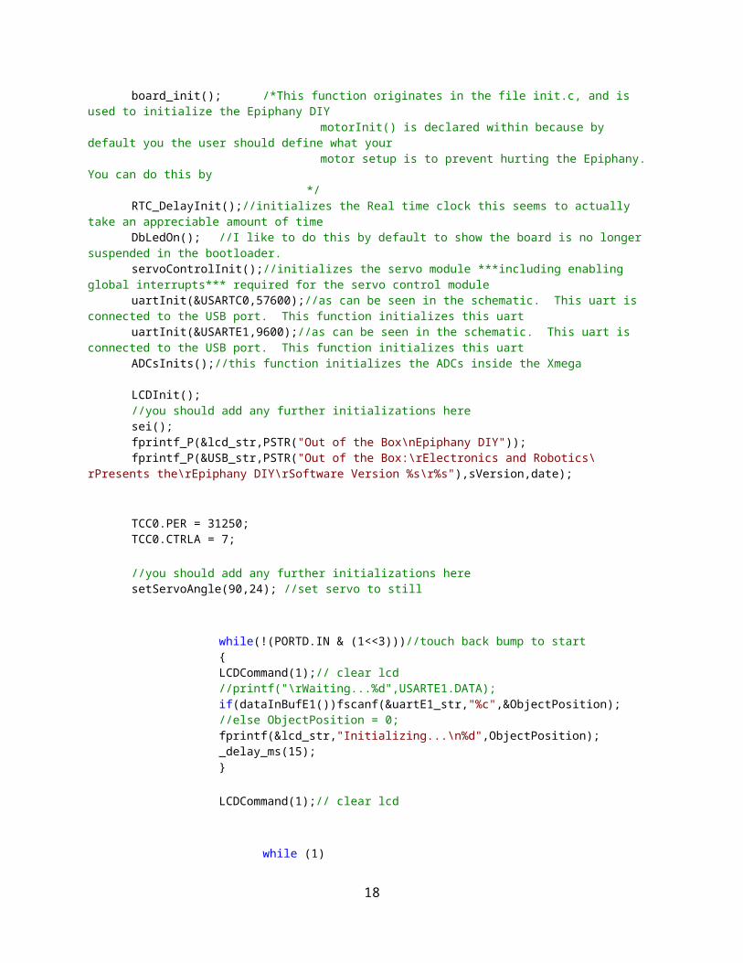
board_init(); /*This function originates in the file init.c, and is used to initialize the Epiphany DIY
motorInit() is declared within because by default you the user should define what your
motor setup is to prevent hurting the Epiphany. You can do this by
*/ RTC_DelayInit();//initializes the Real time clock this seems to actually
take an appreciable amount of timeDbLedOn(); //I like to do this by default to show the board is no longer
suspended in the bootloader.servoControlInit();//initializes the servo module ***including enabling
global interrupts*** required for the servo control module uartInit(&USARTC0,57600);//as can be seen in the schematic. This uart is
connected to the USB port. This function initializes this uartuartInit(&USARTE1,9600);//as can be seen in the schematic. This uart is
connected to the USB port. This function initializes this uartADCsInits();//this function initializes the ADCs inside the Xmega LCDInit();//you should add any further initializations heresei();fprintf_P(&lcd_str,PSTR("Out of the Box\nEpiphany DIY"));fprintf_P(&USB_str,PSTR("Out of the Box:\rElectronics and Robotics\
rPresents the\rEpiphany DIY\rSoftware Version %s\r%s"),sVersion,date);
13

TCC0.PER = 31250;TCC0.CTRLA = 7;
//you should add any further initializations heresetServoAngle(90,24); //set servo to still
while(!(PORTD.IN & (1<<3)))//touch back bump to start{LCDCommand(1);// clear lcd//printf("\rWaiting...%d",USARTE1.DATA);if(dataInBufE1())fscanf(&uartE1_str,"%c",&ObjectPosition);//else ObjectPosition = 0;fprintf(&lcd_str,"Initializing...\n%d",ObjectPosition);_delay_ms(15);}
LCDCommand(1);// clear lcd
while (1){
//unsigned int ObjectPosition = (unsigned int) USARTE1.DATA;
//_delay_ms(20);//LCDCommand(1);// clear lcd//fprintf(&lcd_str,"Waiting for Data\n
%d",ObjectPosition);
if(dataInBufE1()){
newxbee=0;fscanf(&uartE1_str,"%c_
%d",&ObjectPosition,newxbee);_delay_ms(15);
if(ObjectPosition == 0)//obstacle avoidance{
ObsticalAvoidance();}
if(ObjectPosition>0 && ObjectPosition<255)//alignment
{Alignment();
}
if(ObjectPosition==255)//shoot{
Shoot();}
}//ifelse{
14

//setServoAngle(90,24); //set servo to still//newxbee=newxbee+1;//if (newxbee>100)//{
//LCDCommand(1);// clear lcd//fprintf(&lcd_str,"NEED DATA\n%d_
%d",ObjectPosition,newxbee);_delay_ms(15);
setMotorDuty(3,700*speed+terrain,MOTOR_DIR_NEUTRAL_gc);//right motor
setMotorDuty(4,700*speed+terrain,MOTOR_DIR_NEUTRAL_gc);//left motorsetServoAngle(90,24); //set servo to
still//}
}//else
}//while (1)
}//main
Shoot(void){
setMotorDuty(3,700*speed+terrain,MOTOR_DIR_NEUTRAL_gc);//right motorsetMotorDuty(4,700*speed+terrain,MOTOR_DIR_NEUTRAL_gc);//left motorLCDCommand(1);// clear lcdfprintf(&lcd_str,"Shoot!\n%d_%d",ObjectPosition,newxbee);_delay_ms(200);setServoAngle(0,24); //set servo to shoot!_delay_ms(3000);setServoAngle(90,24); //set servo to still_delay_ms(100);
}Alignment(void){
LCDCommand(1);// clear lcdfprintf(&lcd_str,"Alignment\n%d_%d",ObjectPosition,newxbee);_delay_ms(15);setServoAngle(90,24); //set servo to stillk=0;
if(ObjectPosition<115 && ObjectPosition!=0 && ObjectPosition!=255)//object on left so turn left
{ int adjust;adjust=550;
setMotorDuty(3,speed*adjust+terrain,MOTOR_DIR_FORWARD_gc);//right motor
setMotorDuty(4,speed*adjust+terrain,MOTOR_DIR_BACKWARD_gc);//left motor
}
15
else if(ObjectPosition>140 && ObjectPosition!=0 && ObjectPosition!=255)//object on right so turn right
{int adjust;adjust=550;
setMotorDuty(3,speed*adjust+terrain,MOTOR_DIR_BACKWARD_gc);//right motor
setMotorDuty(4,speed*adjust+terrain,MOTOR_DIR_FORWARD_gc);//left motor
}
else if(ObjectPosition<140 && ObjectPosition>115 && ObjectPosition!=255)//creep forward
{int adjust=570;
setMotorDuty(3,speed*adjust+terrain,MOTOR_DIR_FORWARD_gc);//right motor
setMotorDuty(4,speed*adjust+terrain,MOTOR_DIR_FORWARD_gc);//left motor_delay_ms(20);
}else//object in middle or not there, do nothing{
}_delay_ms(25);//turn timesetMotorDuty(3,700*speed+terrain,MOTOR_DIR_NEUTRAL_gc);//right motorsetMotorDuty(4,700*speed+terrain,MOTOR_DIR_NEUTRAL_gc);//left motor
}
ObsticalAvoidance(void){
int left_distance;int right_distance;int center_distance;int motorrrrrr=0;int k=0;
setServoAngle(90,1); //set servo to stillLCDCommand(1);// clear lcd
ADCA_request(0,0);//left irADCA_request(1,1);// right irADCA_request(2,2);// ultrasonic_delay_ms(15);
left_distance=ADCA_getVal(0);right_distance=ADCA_getVal(1);center_distance=ADCA_getVal(2);
fprintf(&lcd_str,"Obstacle Avoidance\n%d_%d",ObjectPosition,newxbee);_delay_ms(15);//center
16

if(center_distance< 230 && left_distance < 1800 && right_distance < 1800)
{
//setMotorDuty(3,680*speed+terrain,MOTOR_DIR_BACKWARD_gc);//right motor
//setMotorDuty(4,680*speed+terrain,MOTOR_DIR_BACKWARD_gc);//left motor//_delay_ms(500);setMotorDuty(3,680*speed+terrain,MOTOR_DIR_FORWARD_gc);//right
motorsetMotorDuty(4,680*speed+terrain,MOTOR_DIR_BACKWARD_gc);//left
motor}//right objectelse if(right_distance>1800){
setMotorDuty(3,680*speed+terrain,MOTOR_DIR_FORWARD_gc);//right motor
setMotorDuty(4,680*speed+terrain,MOTOR_DIR_BACKWARD_gc);//left motor
}//left objectelse if(left_distance>1800){
setMotorDuty(3,680*speed+terrain,MOTOR_DIR_BACKWARD_gc);//right motorsetMotorDuty(4,680*speed+terrain,MOTOR_DIR_FORWARD_gc);//left
motor}else//go straight{
setMotorDuty(3,620*speed+terrain,MOTOR_DIR_FORWARD_gc);//right motor
setMotorDuty(4,620*speed+terrain,MOTOR_DIR_FORWARD_gc);//left motor
}
}
Epiphany DIY-ADC/* * ADC.h * * Created: 9/4/2011 12:54:06 AM * Author: Tim */
#ifndef ADC_H_#define ADC_H_
17
#include <avr/io.h>#include <asf.h>
#define Internal_Temp 0x80 //internal temperature sensor#define Internal_BandGap 0x81 //internal band gap voltage use this for calibrations#define Internal_VccScaled 0x82 //internal vcc/10#define Internal_DAC 0x83 //way of measuring the DAC output#define ADC_InternalChannel_msk 0x80 //Used to detect internal vs external in code
#define ExternalChannel0 0#define ExternalChannel1 1#define ExternalChannel2 2#define ExternalChannel3 3#define ExternalChannel4 4#define ExternalChannel5 5#define ExternalChannel6 6#define ExternalChannel7 7
#define ADCA_CH0_ConvComplete (ADCA.CH0.INTFLAGS & ADC_CH_CHIF_bm) //determines if the conversion has been completed#define ADCA_CH1_ConvComplete (ADCA.CH1.INTFLAGS & ADC_CH_CHIF_bm) //determines if the conversion has been completed#define ADCA_CH2_ConvComplete (ADCA.CH2.INTFLAGS & ADC_CH_CHIF_bm) //determines if the conversion has been completed#define ADCA_CH3_ConvComplete (ADCA.CH3.INTFLAGS & ADC_CH_CHIF_bm) //determines if the conversion has been completed
#define ADCB_CH0_ConvComplete (ADCA.CH0.INTFLAGS & ADC_CH_CHIF_bm) //determines if the conversion has been completed#define ADCB_CH1_ConvComplete (ADCA.CH1.INTFLAGS & ADC_CH_CHIF_bm) //determines if the conversion has been completed#define ADCB_CH2_ConvComplete (ADCA.CH2.INTFLAGS & ADC_CH_CHIF_bm) //determines if the conversion has been completed#define ADCB_CH3_ConvComplete (ADCA.CH3.INTFLAGS & ADC_CH_CHIF_bm) //determines if the conversion has been completed
void ADCsInits(void);//initializes the ADC modulesvoid ADCA_request(uint8_t ADCChannel,uint8_t inputChannel); //get data from any of the 8 external channels or the 4 internal channels. Example choose ExternalChannel0..7 or any of the 4 Internal_... channels.void ADCB_request(uint8_t ADCChannel,uint8_t inputChannel); //get data from any of the 8 external channels or the 4 internal channels. Example choose ExternalChannel0..7 or any of the 4 Internal_... channels.
uint16_t ADCA_getVal(uint8_t ADCChannel);//returns the last chn conversion. 0xFFFF means an error occurred uint16_t ADCB_getVal(uint8_t ADCChannel);//returns the last chn conversion. 0xFFFF means an error occurred
#endif /* ADC_H_ */
/*
18

* ADC.c * * Created: 9/4/2011 12:53:48 AM * Author: Tim */
#include "ADC.h"
void ADCA_request(uint8_t ADCChannel,uint8_t inputChannel){//internal signal to be measured?if (inputChannel & ADC_InternalChannel_msk){
inputChannel &= 0x0F;
switch(ADCChannel){case(0):ADCA.CH0.MUXCTRL = inputChannel<<3;ADCA.CH0.CTRL = ADC_CH_INPUTMODE_INTERNAL_gc | ADC_CH_START_bm;break;case(1):ADCA.CH1.MUXCTRL = inputChannel<<3;ADCA.CH1.CTRL = ADC_CH_INPUTMODE_INTERNAL_gc | ADC_CH_START_bm;break;case(2):ADCA.CH2.MUXCTRL = inputChannel<<3;ADCA.CH2.CTRL = ADC_CH_INPUTMODE_INTERNAL_gc | ADC_CH_START_bm;break;case(3):ADCA.CH3.MUXCTRL = inputChannel<<3;ADCA.CH3.CTRL = ADC_CH_INPUTMODE_INTERNAL_gc | ADC_CH_START_bm;break;default:ADCA.CH0.MUXCTRL = inputChannel<<3;ADCA.CH0.CTRL = ADC_CH_INPUTMODE_INTERNAL_gc | ADC_CH_START_bm;}
}else{
switch(ADCChannel){case(0):ADCA.CH0.MUXCTRL = inputChannel<<3;ADCA.CH0.CTRL = ADC_CH_INPUTMODE_SINGLEENDED_gc | ADC_CH_START_bm;break;case(1):ADCA.CH1.MUXCTRL = inputChannel<<3;ADCA.CH1.CTRL = ADC_CH_INPUTMODE_SINGLEENDED_gc | ADC_CH_START_bm;break;case(2):ADCA.CH2.MUXCTRL = inputChannel<<3;ADCA.CH2.CTRL = ADC_CH_INPUTMODE_SINGLEENDED_gc | ADC_CH_START_bm;break;case(3):ADCA.CH3.MUXCTRL = inputChannel<<3;ADCA.CH3.CTRL = ADC_CH_INPUTMODE_SINGLEENDED_gc | ADC_CH_START_bm;break;default:ADCA.CH0.MUXCTRL = inputChannel<<3;ADCA.CH0.CTRL = ADC_CH_INPUTMODE_SINGLEENDED_gc | ADC_CH_START_bm;}
}}
19

void ADCB_request(uint8_t ADCChannel,uint8_t inputChannel){//internal signal to be measured?if (inputChannel & ADC_InternalChannel_msk){
inputChannel &= 0x0F;
switch(ADCChannel){case(0):ADCB.CH0.MUXCTRL = inputChannel<<3;ADCB.CH0.CTRL = ADC_CH_INPUTMODE_INTERNAL_gc | ADC_CH_START_bm;break;case(1):ADCB.CH1.MUXCTRL = inputChannel<<3;ADCB.CH1.CTRL = ADC_CH_INPUTMODE_INTERNAL_gc | ADC_CH_START_bm;break;case(2):ADCB.CH2.MUXCTRL = inputChannel<<3;ADCB.CH2.CTRL = ADC_CH_INPUTMODE_INTERNAL_gc | ADC_CH_START_bm;break;case(3):ADCB.CH3.MUXCTRL = inputChannel<<3;ADCB.CH3.CTRL = ADC_CH_INPUTMODE_INTERNAL_gc | ADC_CH_START_bm;break;default:ADCB.CH0.MUXCTRL = inputChannel<<3;ADCB.CH0.CTRL = ADC_CH_INPUTMODE_INTERNAL_gc | ADC_CH_START_bm;}
}else{
switch(ADCChannel){case(0):ADCB.CH0.MUXCTRL = inputChannel<<3;ADCB.CH0.CTRL = ADC_CH_INPUTMODE_SINGLEENDED_gc | ADC_CH_START_bm;break;case(1):ADCB.CH1.MUXCTRL = inputChannel<<3;ADCB.CH1.CTRL = ADC_CH_INPUTMODE_SINGLEENDED_gc | ADC_CH_START_bm;break;case(2):ADCB.CH2.MUXCTRL = inputChannel<<3;ADCB.CH2.CTRL = ADC_CH_INPUTMODE_SINGLEENDED_gc | ADC_CH_START_bm;break;case(3):ADCB.CH3.MUXCTRL = inputChannel<<3;ADCB.CH3.CTRL = ADC_CH_INPUTMODE_SINGLEENDED_gc | ADC_CH_START_bm;break;default:ADCB.CH0.MUXCTRL = inputChannel<<3;ADCB.CH0.CTRL = ADC_CH_INPUTMODE_SINGLEENDED_gc | ADC_CH_START_bm;}
}}
uint16_t ADCA_getVal(uint8_t ADCChannel){uint8_t attempts = 0;switch(ADCChannel){
20

case(0):while(!ADCA_CH0_ConvComplete){
attempts++;if(attempts > 4)return 0xFFFF;
}ADCA_CH0_INTFLAGS = ADC_CH_CHIF_bm;//clear bit by writing a
one to itreturn ADCA_CH0RES;
break;case(1):
while(!ADCA_CH1_ConvComplete){attempts++;if(attempts > 4)return 0xFFFF;
}ADCA_CH1_INTFLAGS = ADC_CH_CHIF_bm;//clear bit by writing a
one to itreturn ADCA_CH1RES;
break;case(2):
while(!ADCA_CH2_ConvComplete){attempts++;if(attempts > 4)return 0xFFFF;
}ADCA_CH2_INTFLAGS = ADC_CH_CHIF_bm;//clear bit by writing a
one to itreturn ADCA_CH2RES;
break;case(3):
while(!ADCA_CH3_ConvComplete){attempts++;if(attempts > 4)return 0xFFFF;
}ADCA_CH3_INTFLAGS = ADC_CH_CHIF_bm;//clear bit by writing a
one to itreturn ADCA_CH3RES;
break;default:
return 0xFFFF;break;
}}
uint16_t ADCB_getVal(uint8_t ADCChannel){uint8_t attempts = 0;switch(ADCChannel){
case(0):while(!ADCB_CH0_ConvComplete){
attempts++;if(attempts > 4)return 0xFFFF;
}ADCB_CH0_INTFLAGS = ADC_CH_CHIF_bm;//clear bit by writing a
one to itreturn ADCB_CH0RES;
break;case(1):
while(!ADCB_CH1_ConvComplete){attempts++;if(attempts > 4)return 0xFFFF;
21

}ADCB_CH1_INTFLAGS = ADC_CH_CHIF_bm;//clear bit by writing a
one to itreturn ADCB_CH1RES;
break;case(2):
while(!ADCB_CH2_ConvComplete){attempts++;if(attempts > 4)return 0xFFFF;
}ADCB_CH2_INTFLAGS = ADC_CH_CHIF_bm;//clear bit by writing a
one to itreturn ADCB_CH2RES;
break;case(3):
while(!ADCB_CH3_ConvComplete){attempts++;if(attempts > 4)return 0xFFFF;
}ADCB_CH3_INTFLAGS = ADC_CH_CHIF_bm;//clear bit by writing a
one to itreturn ADCB_CH3RES;
break;default:
return 0xFFFF;break;
}}
void ADCsInits(void){ADCA.CTRLA |= ADC_ENABLE_bm;//enable ADCsADCB.CTRLA |= ADC_ENABLE_bm;
ADCA.REFCTRL = ADC_REFSEL_VCC_gc | ADC_BANDGAP_bm | ADC_TEMPREF_bm; //ref of 2.0625. Due to external circuitry the ref is 5V for the 8 channels that support it. To get the full 5V range make sure the 5V/3.3V jumper above the ADC is jumpered towards 5V. Otherwise signals will be truncated at 5V.
ADCB.REFCTRL = ADC_REFSEL_VCC_gc | ADC_BANDGAP_bm | ADC_TEMPREF_bm; //also bandgap and temp referenaces are initialized.
ADCA.PRESCALER = ADC_PRESCALER_DIV32_gc;//setup for max of 1MHz limited by op-amps
ADCB.PRESCALER = ADC_PRESCALER_DIV32_gc;
/* ADCA.CH0.INTCTRL = ADC_CH_INTLVL_LO_gc | ADC_CH_INTMODE_COMPLETE_gc;ADCA.CH1.INTCTRL = ADC_CH_INTLVL_LO_gc | ADC_CH_INTMODE_COMPLETE_gc;ADCA.CH2.INTCTRL = ADC_CH_INTLVL_LO_gc | ADC_CH_INTMODE_COMPLETE_gc;ADCA.CH3.INTCTRL = ADC_CH_INTLVL_LO_gc | ADC_CH_INTMODE_COMPLETE_gc;
ADCB.CH0.INTCTRL = ADC_CH_INTLVL_LO_gc | ADC_CH_INTMODE_COMPLETE_gc;ADCB.CH1.INTCTRL = ADC_CH_INTLVL_LO_gc | ADC_CH_INTMODE_COMPLETE_gc;ADCB.CH2.INTCTRL = ADC_CH_INTLVL_LO_gc | ADC_CH_INTMODE_COMPLETE_gc;ADCB.CH3.INTCTRL = ADC_CH_INTLVL_LO_gc | ADC_CH_INTMODE_COMPLETE_gc;
PMIC.CTRL |= PMIC_LOLVLEN_bm;*/
22

}
Epiphany DIY-LCD/* * lcd.h * * Created: 7/2/2011 2:18:05 AM * Author: Tim */
#ifndef LCD_H_#define LCD_H_
#include <stdbool.h>#include <avr/io.h>#include <asf/common/boards/user_board/user_board.h>#include <util/delay.h>#include <ctype.h>#include <stdint.h>#include <stdio.h>
#define LCD_BUSY_FLAG 7
#define LCD_CLEAR 0x01#define LCD_HOME 0x02#define LCD_ENTRYMODE 0x06#define LCD_DISPLAYCTRL 0x0C#define LCD_SHIFTCTRL 0x14#define LCD_FUNCSET 0x28
#define LCD_ENABLE 1<<0#define LCD_RW 1<<1#define LCD_RS 1<<2#define LCD_DATA_PIN_msk 0xF0
void LCDInit(void);void LCDSetCursor(uint8_t col, uint8_t row);
//private functionsvoid waitWhileLCDBusy(void);void LCDCommand(uint8_t data);void LCDWrite(uint8_t data);void LCDEnableInterrupt(void);void LCDDisableInterrupt(void);void LCDStrobe(uint8_t read);void outNibble(uint8_t nibble,uint8_t RS);
23

int lcd_putchar(char c, FILE *unused);
FILE lcd_str;
#endif /* LCD_H_ */
/* * lcd.c * * Created: 7/2/2011 2:18:17 AM * Author: Tim */ #include "lcd.h"
FILE lcd_str = FDEV_SETUP_STREAM(lcd_putchar, NULL, _FDEV_SETUP_WRITE);
void LCDInit(void){PORTJ.OUTSET = LCD_RS | LCD_RW;PORTJ.DIRSET = LCD_ENABLE | LCD_RS | LCD_RW | LCD_DATA_PIN_msk;
PORTJ.PIN4CTRL = 0x10;PORTJ.PIN5CTRL = 0x10;PORTJ.PIN6CTRL = 0x10;PORTJ.PIN7CTRL = 0x10;
_delay_ms(10);PORTJ.OUTCLR = LCD_RS | LCD_RW;_delay_ms(50);outNibble(0x30,0);
_delay_ms(5);outNibble(0x30,0);
_delay_ms(.2);outNibble(0x30,0);
outNibble(0x20,0);waitWhileLCDBusy();LCDCommand(0x28);waitWhileLCDBusy();LCDCommand(0x0C);waitWhileLCDBusy();LCDCommand(0x01);waitWhileLCDBusy();LCDCommand(0x06);
/* waitWhileLCDBusy();LCDCommand(LCD_FUNCSET);waitWhileLCDBusy();LCDCommand(LCD_DISPLAYCTRL);waitWhileLCDBusy();LCDCommand(LCD_SHIFTCTRL);waitWhileLCDBusy();
24

LCDCommand(LCD_CLEAR);waitWhileLCDBusy();LCDCommand(LCD_HOME);
*/}void waitWhileLCDBusy(void){
PORTJ.DIRCLR = LCD_DATA_PIN_msk;PORTJ.OUTCLR = 0xF0;PORTJ.OUTCLR = LCD_RS;PORTJ.OUTSET = LCD_RW;_delay_us(1);LCDStrobe(1);LCDStrobe(0);PORTJ.DIRSET = LCD_DATA_PIN_msk;
}void LCDCommand(uint8_t data){
outNibble(data,0);outNibble(data<<4,0);
}void LCDWrite(uint8_t data){
waitWhileLCDBusy();outNibble(data,1);outNibble(data<<4,1);
}void LCDSetCursor(uint8_t col, uint8_t row){
}void LCDEnableInterrupt(){
}void LCDDisableInterrupt(){
}void LCDStrobe(uint8_t read){PORTJ.OUTSET = LCD_ENABLE;_delay_us(3);
if(read){while(PORTJ.IN & 0x80);}
PORTJ.OUTCLR = LCD_ENABLE;_delay_us(3);}
void outNibble(uint8_t nibble,uint8_t RS){
PORTJ.OUTCLR = LCD_RW;
if(RS)PORTJ.OUTSET = LCD_RS;else PORTJ.OUTCLR = LCD_RS;PORTJ.OUTCLR = 0xF0;PORTJ.OUTSET = nibble & 0xF0;LCDStrobe(0);
}
int lcd_putchar(char c, FILE *unused){ static bool nl_seen,cr_seen;
25

if(cr_seen && c != '\r'){ waitWhileLCDBusy(); LCDCommand(LCD_CLEAR);
waitWhileLCDBusy(); LCDCommand(LCD_HOME);
waitWhileLCDBusy();// hd44780_outcmd(HD44780_DDADDR(0));
cr_seen = false; } else if(c == '\r'){
cr_seen = true; } else if (nl_seen && c != '\n') {
/* * First character after newline, move cursor to next line. */
waitWhileLCDBusy(); LCDCommand(0x80 | 0x40); //hd44780_outcmd(HD44780_DDADDR(0x40)); nl_seen = false;
} if (c == '\n') { nl_seen = true; } else { waitWhileLCDBusy();
LCDWrite(c); }
return 0;}
Epiphany DIY-motors/* * motor.h * * Created: 7/2/2011 1:13:38 AM * Author: Tim */
#ifndef MOTOR_H_#define MOTOR_H_
#include <avr/io.h>#include <asf.h>
#define MOTOR_PERIOD_gc 1024 //This is the maximum value for PWM. Duty cycle is (value/1024)*100%
26

#define Motor_CLKSEL_DIV_gc TC_CLKSEL_DIV1_gc //setting of a division of 1 prescaler. So in other words there is no prescaler
#define MOTOR_DIR_NEUTRAL_gc 0 //disables braking, and control of the motor#define MOTOR_DIR_FORWARD_gc 1 //configures the motor for forward drive assuming your wiring is correct#define MOTOR_DIR_BACKWARD_gc 2 //configures the motor for backward drive assuming your wiring is correct#define MOTOR_DIR_BRAKE_gc 3 /*brakes the motor quickly. This may cause amperage spikes due to motors being an inductive load
use with caution.*/void motorInit(void); //this function reinitializes the motor driving modules of the Epiphany DIY void setMotorDuty(uint8_t motorNumber, uint16_t duty,uint8_t direction);/*This function is used to set the duty of a motor. MotorNumber is the motor in question duty is a misnomer because it is not the % duty but a disticnt value 0-1024. The direction can be specified easily by defines I have created Motor_DIR_..._gc */#endif /* MOTOR_H_ */
/* * motor.c * * Created: 7/2/2011 1:13:25 AM * Author: Tim */
#include "motor.h"
void motorInit(void){
//set motor period for 1024... 32000000/1024 = 31.25kHz PWM. this frequency is above audible
TCF0.PER = MOTOR_PERIOD_gc;TCF0.CTRLA = Motor_CLKSEL_DIV_gc;
#if (F_CPU == 2000000L)#warning "F_CPU is defined as 2MHz this will make motors whine and sound annoying"#endif
/*enable the motor control lines and single slope PWMand initialize motor speed as zero*/
#if (motorCtrlMode == quadMode)TCF0.CTRLB = TC0_CCAEN_bm | TC0_CCBEN_bm | TC0_CCCEN_bm | TC0_CCDEN_bm |
TC_WGMODE_SS_gc;TCF0.CCA = 0;TCF0.CCB = 0;TCF0.CCC = 0;TCF0.CCD = 0;
#elif (motorCtrlMode == dualModeDoubleChip)
27

TCF0.CTRLB = TC0_CCBEN_bm | TC0_CCDEN_bm | TC_WGMODE_SS_gc;TCF0.CCB = 0;TCF0.CCD = 0;
#elif (motorCtrlMode == dualModeSingleChip)TCF0.CTRLB = TC0_CCCEN_bm | TC0_CCDEN_bm | TC_WGMODE_SS_gc;TCF0.CCC = 0;TCF0.CCD = 0;
#else//do nothing because motor control is disconnected
#endif}
void setMotorDuty(uint8_t motorNumber, uint16_t duty,uint8_t direction){
motorNumber--;//this fixes the error of the silkscreen vs code numberingif (duty>MOTOR_PERIOD_gc) duty = MOTOR_PERIOD_gc;
switch (motorNumber){case (0):
TCF0.CCA = duty;PORTK.OUTSET = direction<<(motorNumber<<1);PORTK.OUTCLR = 0x3<<(motorNumber<<1) &
(~direction)<<(motorNumber<<1);break;
case (1):TCF0.CCB = duty;PORTK.OUTSET = direction<<(motorNumber<<1);PORTK.OUTCLR = 0x3<<(motorNumber<<1) &
(~direction)<<(motorNumber<<1);break;
case (2):TCF0.CCC = duty;PORTK.OUTSET = direction<<(motorNumber<<1);PORTK.OUTCLR = 0x3<<(motorNumber<<1) &
(~direction)<<(motorNumber<<1);break;
case (3):TCF0.CCD = duty;PORTK.OUTSET = direction<<(motorNumber<<1);PORTK.OUTCLR = 0x3<<(motorNumber<<1) &
(~direction)<<(motorNumber<<1);break;
default://do nothing motor number was incorrectly specifiedbreak;
}}
Epiphany DIY-Servo/* * picServo.h *
28

* Created: 7/9/2011 3:09:39 AM * Author: Tim */
#ifndef PICSERVO_H_#define PICSERVO_H_
#include <stdbool.h>#include <asf.h>#include <stdio.h>#include "uart.h"
#define updateMsgHeader 0x55#define controlHeader 0xCC
volatile uint8_t angles[24];//this is the array that holds all of the data used for controlling servos
volatile uint8_t currentAngle;//current angle being pointed to by the servo control code
void setServoAngle(uint8_t data, uint8_t servoNumber);//use this function to set a new angle for the servo to go touint8_t getServoAngle(uint8_t servoNumber);//use this function to get the angle the servo is currently atvoid servoControlInit(void);/*used to initialize the servo control unit*///void sendServoUpdateMsg(void);
#endif /* PICSERVO_H_ */
/* * picServo.c * * Created: 7/9/2011 3:09:24 AM * Author: Tim */
#include "picServo.h"
void setServoAngle(uint8_t data, uint8_t servoNumber){if(data > 180)data=180;//prevents erroneous valuesangles[servoNumber-1] = data;
}uint8_t getServoAngle(uint8_t servoNumber){
return angles[servoNumber-1];}
void servoControlInit(){uartInit(&USARTE0,57600);uint8_t i;PMIC.CTRL = PMIC_MEDLVLEN_bm;
29

//initializes global interrupts. This is required to make the servo controller work.
sei();//This for loop initializes all the servos to 90 degrees at startup. If
this is not preferable//just set the angle to something different for all the servos, or
individuals for that matter.for(i=0;i<24;i++)angles[i] = 90;
/* DMA.CH0.CTRLA = DMA_CH_ENABLE_bm | DMA_CH_SINGLE_bm;//| DMA_CH_REPEAT_bm;
DMA.CH0.ADDRCTRL = DMA_CH_SRCRELOAD_BURST_gc | DMA_CH_SRCDIR_INC_gc; //set the params for source reload and fix the destination
DMA.CH0.TRIGSRC = 0x8B; //set trigger of DMA to USARTE0 RX interruptDMA.CH0.TRFCNT = 24;
DMA.CH0.SRCADDR2 = (uint8_t)((&angles)>>16);DMA.CH0.SRCADDR1 = (uint8_t)(0xFF & ((&angles)>>8));DMA.CH0.SRCADDR0 = (uint8_t)(0xFF & (&angles));
DMA.CH0.DESTADDR2 = (uint8_t)((&USARTE0.DATA)>>16);DMA.CH0.DESTADDR1 = (uint8_t)(0xFF & ((&USARTE0.DATA)>>8));DMA.CH0.DESTADDR0 = (uint8_t)(0xFF & (&USARTE0.DATA));
DMA.CTRL |= DMA_ENABLE_bm; //enable DMA*/
}
ISR(USARTE0_RXC_vect){cli();//diables interrupts so that this code is not disturbeduint16_t temp = stdout; //temp is used to preserve the current device
being used by stdout.stdout = &uartE0_str; //now the pic can be spoken tochar msg = USARTE0.DATA; //read in the data from the pic.
//first byte that is sentif(msg == 'r'){
printf("%c",angles[23]);currentAngle = 0;
} //for ever byte thereafterelse if(msg == 'n'){
printf("%c",angles[currentAngle++]);}//used for error handlingelse {
printf("%c",msg);}stdout = temp; //Puts stdout back to the way it was.sei();//re-enables interrupts now that the routine is finished.
}
30

Epiphany DIY-UART/* * uart.h * * Created: 7/7/2011 9:55:37 PM * Author: Tim */
#ifndef UART_H_#define UART_H_
#include <ctype.h>#include <stdint.h>#include <stdio.h>#include <avr/io.h>#include <avr/interrupt.h>#include <asf.h>
#define enableUartC1#define enableUartD0#define enableUartD1#define enableUartE0#define enableUartE1#define enableUartF0#define enableUartF1
//1200#define BAUD1200 3331#define USART_BAUDCTRLA_1200 BAUD1200#define USART_BAUDCTRLB_1200 0xC0 | (uint16_t)(0x0FFF & BAUD1200>>8)#define USART_CTRLB_1200 USART_RXEN_bm | USART_TXEN_bm
//2400#define BAUD2400 3329#define USART_BAUDCTRLA_2400 BAUD2400#define USART_BAUDCTRLB_2400 0xE0 | (uint16_t)(0x0FFF & BAUD2400>>8)#define USART_CTRLB_2400 USART_RXEN_bm | USART_TXEN_bm
//4800#define BAUD4800 3325#define USART_BAUDCTRLA_4800 BAUD4800#define USART_BAUDCTRLB_4800 0xD0 | (uint16_t)(0x0FFF & BAUD4800>>8)#define USART_CTRLB_4800 USART_RXEN_bm | USART_TXEN_bm
//9600#define BAUD9600 3317#define USART_BAUDCTRLA_9600 BAUD9600#define USART_BAUDCTRLB_9600 0xC0 | (uint16_t)(0x0FFF & BAUD9600>>8)#define USART_CTRLB_9600 USART_RXEN_bm | USART_TXEN_bm
//14400#define BAUD14400 2206#define USART_BAUDCTRLA_14400 BAUD14400#define USART_BAUDCTRLB_14400 0xC0 | (uint16_t)(0x0FFF & BAUD14400>>8)#define USART_CTRLB_14400 USART_RXEN_bm | USART_TXEN_bm
31

//19200#define BAUD19200 3317#define USART_BAUDCTRLA_19200 BAUD19200#define USART_BAUDCTRLB_19200 0xC0 | (uint16_t)(0x0FFF & BAUD19200>>8)#define USART_CTRLB_19200 USART_RXEN_bm | USART_TXEN_bm | USART_CLK2X_bm
//28800#define BAUD28800 2206#define USART_BAUDCTRLA_28800 BAUD28800#define USART_BAUDCTRLB_28800 0xC0 | (uint16_t)(0x0FFF & BAUD28800>>8)#define USART_CTRLB_28800 USART_RXEN_bm | USART_TXEN_bm | USART_CLK2X_bm
//38400#define BAUD38400 3301#define USART_BAUDCTRLA_38400 BAUD38400#define USART_BAUDCTRLB_38400 0xB0 | (uint16_t)(0x0FFF & BAUD38400>>8)#define USART_CTRLB_38400 USART_RXEN_bm | USART_TXEN_bm | USART_CLK2X_bm
//56000#define BAUD56000 2254#define USART_BAUDCTRLA_56000 BAUD56000#define USART_BAUDCTRLB_56000 0xB0 | (uint16_t)(0x0FFF & BAUD56000>>8)#define USART_CTRLB_56000 USART_RXEN_bm | USART_TXEN_bm | USART_CLK2X_bm
//57600#define BAUD57600 2190#define USART_BAUDCTRLA_57600 BAUD57600#define USART_BAUDCTRLB_57600 0xB0 | (uint16_t)(0x0FFF & BAUD57600>>8)#define USART_CTRLB_57600 USART_RXEN_bm | USART_TXEN_bm | USART_CLK2X_bm
//115200#define BAUD115200 2158#define USART_BAUDCTRLA_115200 BAUD115200#define USART_BAUDCTRLB_115200 0xA0 | (uint16_t)(0x0FFF & BAUD115200>>8)#define USART_CTRLB_115200 USART_RXEN_bm | USART_TXEN_bm | USART_CLK2X_bm
//230400#define BAUD230400 2094#define USART_BAUDCTRLA_230400 BAUD230400#define USART_BAUDCTRLB_230400 0x90 | (uint16_t)(0x0FFF & BAUD230400>>8)#define USART_CTRLB_230400 USART_RXEN_bm | USART_TXEN_bm | USART_CLK2X_bm
void uartInit(USART_t *uart, long baud);//inilization routine for uart modules. uart = &USARTxn where x is C-F n is 0-1void uartF0_putchar(char c,FILE *unused);//uart output functionvoid uartF1_putchar(char c,FILE *unused);//uart output functionvoid uartE0_putchar(char c,FILE *unused);//uart output functionvoid uartE1_putchar(char c,FILE *unused);//uart output functionvoid uartD0_putchar(char c,FILE *unused);//uart output functionvoid uartD1_putchar(char c,FILE *unused);//uart output functionvoid uartC0_putchar(char c,FILE *unused);//uart output functionvoid uartC1_putchar(char c,FILE *unused);//uart output function
int uartC0_getchar(FILE *stream);
32

uint8_t dataInBufC0(void);void storeC0(char c);
int uartC1_getchar(FILE *stream);uint8_t dataInBufC1(void);void storeC1(char c);
int uartD0_getchar(FILE *stream);uint8_t dataInBufD0(void);void storeD0(char c);
int uartD1_getchar(FILE *stream);uint8_t dataInBufD1(void);void storeD1(char c);
int uartE0_getchar(FILE *stream);uint8_t dataInBufE0(void);void storeE0(char c);
int uartE1_getchar(FILE *stream);uint8_t dataInBufE1(void);void storeE1(char c);
int uartF0_getchar(FILE *stream);uint8_t dataInBufF0(void);void storeF0(char c);
int uartF1_getchar(FILE *stream);uint8_t dataInBufF1(void);void storeF1(char c);
FILE uartC0_str;FILE uartC1_str;
FILE uartD0_str;FILE uartD1_str;
FILE uartE0_str;FILE uartE1_str;
FILE uartF0_str;FILE uartF1_str;
#define USB_str uartC0_str#define Xbee_str uartE1_str#define Servo_str uartE0_str
#endif /* UART_H_ */
/* * uart.c * * Created: 7/7/2011 9:55:17 PM * Author: Tim
33

*/ #include "uart.h"
#define bufferSize 64
struct Buffer{const uint8_t *bufferBegin;const uint8_t *bufferEnd;uint8_t *head;uint8_t *tail;uint8_t data[bufferSize];
}bufC0//#ifdef enableUartC1,bufC1//#endif//#ifdef enableUartD0,bufD0//#endif//#ifdef enableUartD1,bufD1//#endif//#ifdef enableUartE0,bufE0//#endif//#ifdef enableUartE1,bufE1//#endif//#ifdef enableUartF0,bufF0//#endif//#ifdef enableUartF1,bufF1//#endif;
//sets up all of the streams
FILE uartC0_str = FDEV_SETUP_STREAM(uartC0_putchar, uartC0_getchar, _FDEV_SETUP_RW);FILE uartC1_str = FDEV_SETUP_STREAM(uartC1_putchar, uartC1_getchar, _FDEV_SETUP_RW);
FILE uartD0_str = FDEV_SETUP_STREAM(uartD0_putchar, uartD0_getchar, _FDEV_SETUP_RW);FILE uartD1_str = FDEV_SETUP_STREAM(uartD1_putchar, uartD1_getchar, _FDEV_SETUP_RW);
//FILE uartE0_str = FDEV_SETUP_STREAM(uartE0_putchar, uartE0_getchar, _FDEV_SETUP_RW);FILE uartE0_str = FDEV_SETUP_STREAM(uartE0_putchar, NULL, _FDEV_SETUP_WRITE);
FILE uartE1_str = FDEV_SETUP_STREAM(uartE1_putchar, uartE1_getchar, _FDEV_SETUP_RW);
FILE uartF0_str = FDEV_SETUP_STREAM(uartF0_putchar, uartF0_getchar, _FDEV_SETUP_RW);FILE uartF1_str = FDEV_SETUP_STREAM(uartF1_putchar, uartF1_getchar, _FDEV_SETUP_RW);
34

//these functions are used for outputing data from the uarts
void uartF0_putchar(char c,FILE *unused){
while(!(USARTF0.STATUS & USART_DREIF_bm));USARTF0.DATA = c;
}void uartF1_putchar(char c,FILE *unused){
while(!(USARTF1.STATUS & USART_DREIF_bm));USARTF1.DATA = c;
}void uartE0_putchar(char c,FILE *unused){
while(!(USARTE0.STATUS & USART_DREIF_bm));USARTE0.DATA = c;
}void uartE1_putchar(char c,FILE *unused){
while(!(USARTE1.STATUS & USART_DREIF_bm));USARTE1.DATA = c;
}void uartD0_putchar(char c,FILE *unused){
while(!(USARTD0.STATUS & USART_DREIF_bm));USARTD0.DATA = c;
}void uartD1_putchar(char c,FILE *unused){
while(!(USARTD1.STATUS & USART_DREIF_bm));USARTD1.DATA = c;
}void uartC0_putchar(char c,FILE *unused){
while(!(USARTC0.STATUS & USART_DREIF_bm));USARTC0.DATA = c;
}void uartC1_putchar(char c,FILE *unused){
while(!(USARTC1.STATUS & USART_DREIF_bm));USARTC1.DATA = c;
}
int uartC0_getchar(FILE *stream){
if (bufC0.tail == bufC0.bufferEnd){uint8_t temp = *bufC0.tail;bufC0.tail = bufC0.bufferBegin;return temp;
}else return *bufC0.tail++;
}
void storeC0(char c){if(bufC0.head == bufC0.bufferEnd){
*bufC0.head = c;
35
bufC0.head = bufC0.bufferBegin;}else *bufC0.head++ = c;
}
uint8_t dataInBufC0(void){if(bufC0.head == bufC0.tail) return 0; //no data to be readelse return 1; //data to be read
}ISR(USARTC0_RXC_vect){
storeC0(USARTC0.DATA);}
#ifdef enableUartC1
int uartC1_getchar(FILE *stream){
if (bufC1.tail == bufC1.bufferEnd){uint8_t temp = *bufC1.tail;bufC1.tail = bufC1.bufferBegin;return temp;
}else return *bufC1.tail++;
}
void storeC1(char c){if(bufC1.head == bufC1.bufferEnd){
*bufC1.head = c;bufC1.head = bufC1.bufferBegin;
}else *bufC1.head++ = c;
}
uint8_t dataInBufC1(void){if(bufC1.head == bufC1.tail) return 0; //no data to be readelse return 1; //data to be read
}ISR(USARTC1_RXC_vect){
storeC1(USARTC1.DATA);}
#endif
#ifdef enableUartD0
int uartD0_getchar(FILE *stream){
if (bufD0.tail == bufD0.bufferEnd){uint8_t temp = *bufD0.tail;bufD0.tail = bufD0.bufferBegin;return temp;
}else return *bufD0.tail++;
}
void storeD0(char c){if(bufD0.head == bufD0.bufferEnd){
*bufD0.head = c;
36

bufD0.head = bufD0.bufferBegin;}else *bufD0.head++ = c;
}
uint8_t dataInBufD0(void){if(bufD0.head == bufD0.tail) return 0; //no data to be readelse return 1; //data to be read
}ISR(USARTD0_RXC_vect){
storeD0(USARTD0.DATA);}
#endif
#ifdef enableUartD1
int uartD1_getchar(FILE *stream){
if (bufD1.tail == bufD1.bufferEnd){uint8_t temp = *bufD1.tail;bufD1.tail = bufD1.bufferBegin;return temp;
}else return *bufD1.tail++;
}
void storeD1(char c){if(bufD1.head == bufD1.bufferEnd){
*bufD1.head = c;bufD1.head = bufD1.bufferBegin;
}else *bufD1.head++ = c;
}
uint8_t dataInBufD1(void){if(bufD1.head == bufD1.tail) return 0; //no data to be readelse return 1; //data to be read
}ISR(USARTD1_RXC_vect){
storeD1(USARTD1.DATA);}
#endif
#ifdef enableUartE0
int uartE0_getchar(FILE *stream){
if (bufE0.tail == bufE0.bufferEnd){uint8_t temp = *bufE0.tail;bufE0.tail = bufE0.bufferBegin;return temp;
}else return *bufE0.tail++;
}
void storeE0(char c){
37
if(bufE0.head == bufE0.bufferEnd){*bufE0.head = c;bufE0.head = bufE0.bufferBegin;
}else *bufE0.head++ = c;
}
uint8_t dataInBufE0(void){if(bufE0.head == bufE0.tail) return 0; //no data to be readelse return 1; //data to be read
}/*ISR(USARTE0_RXC_vect){
storeE0(USARTE0.DATA);}*/#endif
#ifdef enableUartE1
int uartE1_getchar(FILE *stream){
if (bufE1.tail == bufE1.bufferEnd){uint8_t temp = *bufE1.tail;bufE1.tail = bufE1.bufferBegin;return temp;
}else return *bufE1.tail++;
}
void storeE1(char c){if(bufE1.head == bufE1.bufferEnd){
*bufE1.head = c;bufE1.head = bufE1.bufferBegin;
}else *bufE1.head++ = c;
}
uint8_t dataInBufE1(void){if(bufE1.head == bufE1.tail) return 0; //no data to be readelse return 1; //data to be read
}ISR(USARTE1_RXC_vect){
storeE1(USARTE1.DATA);}
#endif
#ifdef enableUartF0
int uartF0_getchar(FILE *stream){
if (bufF0.tail == bufF0.bufferEnd){uint8_t temp = *bufF0.tail;bufF0.tail = bufF0.bufferBegin;return temp;
}else return *bufF0.tail++;
38

}
void storeF0(char c){if(bufF0.head == bufF0.bufferEnd){
*bufF0.head = c;bufF0.head = bufF0.bufferBegin;
}else *bufF0.head++ = c;
}
uint8_t dataInBufF0(void){if(bufF0.head == bufF0.tail) return 0; //no data to be readelse return 1; //data to be read
}ISR(USARTF0_RXC_vect){
storeF0(USARTF0.DATA);}
#endif
#ifdef enableUartF0
int uartF1_getchar(FILE *stream){
if (bufF1.tail == bufF1.bufferEnd){uint8_t temp = *bufF1.tail;bufF1.tail = bufF1.bufferBegin;return temp;
}else return *bufF1.tail++;
}
void storeF1(char c){if(bufF1.head == bufF1.bufferEnd){
*bufF1.head = c;bufF1.head = bufF1.bufferBegin;
}else *bufF1.head++ = c;
}
uint8_t dataInBufF1(void){if(bufF1.head == bufF1.tail) return 0; //no data to be readelse return 1; //data to be read
}ISR(USARTF1_RXC_vect){
storeF1(USARTF1.DATA);}
#endif
//initialization functions for the uartsvoid uartInit(USART_t *uart, long baud){
PMIC.CTRL |= PMIC_MEDLVLEX_bm;if (uart == &USARTC0) {
PORTC.DIRSET = 0x8;bufC0.bufferEnd = &bufC0.data[bufferSize-1];bufC0.bufferBegin = &bufC0.data[0];
39

bufC0.head = bufC0.bufferBegin;bufC0.tail = bufC0.bufferBegin;asm("nop");
}else if (uart == &USARTC1) PORTC.DIRSET = 0x80;else if (uart == &USARTD0) PORTD.DIRSET = 0x8;else if (uart == &USARTD1) PORTD.DIRSET = 0x80;else if (uart == &USARTE0) PORTE.DIRSET = 0x8;else if (uart == &USARTE1) {
PORTE.DIRSET = 0x80;bufE1.bufferEnd = &bufE1.data[bufferSize-1];bufE1.bufferBegin = &bufE1.data[0];bufE1.head = bufE1.bufferBegin;bufE1.tail = bufE1.bufferBegin;asm("nop");
}else if (uart == &USARTF0) PORTF.DIRSET = 0x8;else if (uart == &USARTF1) PORTF.DIRSET = 0x80;
uart->CTRLA |= USART_RXCINTLVL_MED_gc;switch(baud){
case (1200):uart->CTRLB = USART_CTRLB_1200;uart->CTRLC = USART_CMODE_ASYNCHRONOUS_gc |
USART_PMODE_DISABLED_gc | USART_CHSIZE_8BIT_gc;uart->BAUDCTRLA = USART_BAUDCTRLA_1200;uart->BAUDCTRLB = USART_BAUDCTRLB_1200;
break;case (4800):
uart->CTRLB = USART_CTRLB_4800;uart->CTRLC = USART_CMODE_ASYNCHRONOUS_gc |
USART_PMODE_DISABLED_gc | USART_CHSIZE_8BIT_gc;uart->BAUDCTRLA = USART_BAUDCTRLA_4800;uart->BAUDCTRLB = USART_BAUDCTRLB_4800;
break;case (9600):
uart->CTRLB = USART_CTRLB_9600;uart->CTRLC = USART_CMODE_ASYNCHRONOUS_gc |
USART_PMODE_DISABLED_gc | USART_CHSIZE_8BIT_gc;uart->BAUDCTRLA = USART_BAUDCTRLA_9600;uart->BAUDCTRLB = USART_BAUDCTRLB_9600;
break;case (14400):
uart->CTRLB = USART_CTRLB_14400;uart->CTRLC = USART_CMODE_ASYNCHRONOUS_gc |
USART_PMODE_DISABLED_gc | USART_CHSIZE_8BIT_gc;uart->BAUDCTRLA = USART_BAUDCTRLA_14400;uart->BAUDCTRLB = USART_BAUDCTRLB_14400;
break;case (19200):
uart->CTRLB = USART_CTRLB_19200;uart->CTRLC = USART_CMODE_ASYNCHRONOUS_gc |
USART_PMODE_DISABLED_gc | USART_CHSIZE_8BIT_gc;uart->BAUDCTRLA = USART_BAUDCTRLA_19200;uart->BAUDCTRLB = USART_BAUDCTRLB_19200;
break;
40

case (28800):uart->CTRLB = USART_CTRLB_28800;uart->CTRLC = USART_CMODE_ASYNCHRONOUS_gc |
USART_PMODE_DISABLED_gc | USART_CHSIZE_8BIT_gc;uart->BAUDCTRLA = USART_BAUDCTRLA_28800;uart->BAUDCTRLB = USART_BAUDCTRLB_28800;
break;case (38400):
uart->CTRLB = USART_CTRLB_38400;uart->CTRLC = USART_CMODE_ASYNCHRONOUS_gc |
USART_PMODE_DISABLED_gc | USART_CHSIZE_8BIT_gc;uart->BAUDCTRLA = USART_BAUDCTRLA_38400;uart->BAUDCTRLB = USART_BAUDCTRLB_38400;
break;case (56000):
uart->CTRLB = USART_CTRLB_56000;uart->CTRLC = USART_CMODE_ASYNCHRONOUS_gc |
USART_PMODE_DISABLED_gc | USART_CHSIZE_8BIT_gc;uart->BAUDCTRLA = USART_BAUDCTRLA_56000;uart->BAUDCTRLB = USART_BAUDCTRLB_56000;
break;case (57600):
uart->CTRLB = USART_CTRLB_57600;uart->CTRLC = USART_CMODE_ASYNCHRONOUS_gc |
USART_PMODE_DISABLED_gc | USART_CHSIZE_8BIT_gc;uart->BAUDCTRLA = USART_BAUDCTRLA_57600;uart->BAUDCTRLB = USART_BAUDCTRLB_57600;
break;case (115200):
uart->CTRLB = USART_CTRLB_115200;uart->CTRLC = USART_CMODE_ASYNCHRONOUS_gc |
USART_PMODE_DISABLED_gc | USART_CHSIZE_8BIT_gc;uart->BAUDCTRLA = USART_BAUDCTRLA_115200;uart->BAUDCTRLB = USART_BAUDCTRLB_115200;
break;case (230400):
uart->CTRLB = USART_CTRLB_230400;uart->CTRLC = USART_CMODE_ASYNCHRONOUS_gc |
USART_PMODE_DISABLED_gc | USART_CHSIZE_8BIT_gc;uart->BAUDCTRLA = USART_BAUDCTRLA_230400;uart->BAUDCTRLB = USART_BAUDCTRLB_230400;
break;default:
// invalid baud rate defaulting to 9600
uart->CTRLB = USART_CTRLB_9600;uart->CTRLC = USART_CMODE_ASYNCHRONOUS_gc |
USART_PMODE_DISABLED_gc | USART_CHSIZE_8BIT_gc;uart->BAUDCTRLA = USART_BAUDCTRLA_9600;uart->BAUDCTRLB = USART_BAUDCTRLB_9600;
break;}
}
41

OpenCV- modified code from www.technical-recipes.com// ColorTracking.cpp : Defines the entry point for the console application.//
#include "stdafx.h"#include "stdio.h"#include "cvaux.h"#include "stdlib.h"#include "cv.h"#include "highgui.h"#include "COMfunct.h"
// ObjectTracking.cpp : Define the entry point for console app. #include "cv.h" #include "highgui.h" #include "BlobResult.h" // Get thresholded image in HSV format IplImage* GetThresholdedImageHSV( IplImage* img ) { // Create an HSV format image from image passed IplImage* imgHSV = cvCreateImage( cvGetSize( img ), 8, 3 ); cvCvtColor( img, imgHSV, CV_BGR2HSV ); // Create binary thresholded image acc. to max/min HSV ranges // For detecting blue gloves in "MOV.MPG - HSV mode IplImage* imgThresh = cvCreateImage( cvGetSize( img ), 8, 1 );
//cvInRangeS( imgHSV, cvScalar( 104, 178, 70 ), cvScalar( 130, 240, 124 ), imgThresh );
//cvInRangeS(imgHSV, cvScalar(104, 178, 70), cvScalar(130, 240, 124), imgThresh);//blue
//cvInRangeS(imgHSV, cvScalar(0, 100, 100), cvScalar(10, 255, 255), imgThresh);//red
cvInRangeS(imgHSV, cvScalar(60, 120, 120), cvScalar(100, 255, 255), imgThresh);//blue light
// Tidy up and return thresholded image cvReleaseImage( &imgHSV ); return imgThresh; } int main() {
COM_Index INDEX;HANDLE COMPORT;COMPORT = OpenCom(6);//com portint resx=320;
42
CBlobResult blobs; CBlob *currentBlob; CvPoint pt1, pt2; CvRect cvRect; int key = 0; IplImage* frame = 0;
int posX=0;int posY=0;
//WriteCom(COMPORT, 0, 1);//out to comport set to 0 // Initialize capturing live feed from video file or camera //CvCapture* capture = cvCaptureFromCAM(0); //webcam
CvCapture* capture = 0;//capture = cvCaptureFromCAM(0); //webcamcapture = cvCreateFileCapture("http://1.1.1.3/videostream.cgi?
user=admin&pwd=&resolution=8&rate=0&a=.mjpg"); // For IP cam // Get the frames per second /////int fps = ( int )cvGetCaptureProperty( capture, CV_CAP_PROP_FPS ); // Can't get device? Complain and quit if( !capture ) { printf( "Could not initialize capturing...\n" ); return -1; } // Windows used to display input video with bounding rectangles // and the thresholded video cvNamedWindow( "video" ); cvNamedWindow( "thresh" ); // An infinite loop while( key != 'x' ) { // If we couldn't grab a frame... quit if( !( frame = cvQueryFrame( capture ) ) ) break; // Get object's thresholded image (blue = white, rest = black) IplImage* imgThresh = GetThresholdedImageHSV( frame ); // Detect the white blobs from the black background blobs = CBlobResult( imgThresh, NULL, 0 ); // Exclude white blobs smaller than the given value (10) // The bigger the last parameter, the bigger the blobs need // to be for inclusion blobs.Filter( blobs, B_EXCLUDE,CBlobGetArea(),B_LESS,5); // Attach a bounding rectangle for each blob discovered int num_blobs = blobs.GetNumBlobs();
43

//arrays for averaging centersint *StoreX= new int[num_blobs];int *StoreY= new int[num_blobs];
int avgx=0;int avgy=0;
//int StoreX [100];//int StoreY [100];
for ( int i = 0; i < num_blobs; i++ ) { currentBlob = blobs.GetBlob( i ); cvRect = currentBlob->GetBoundingBox(); pt1.x = cvRect.x; pt1.y = cvRect.y; pt2.x = cvRect.x + cvRect.width; pt2.y = cvRect.y + cvRect.height;
posX=(pt2.x+pt1.x)/2;posY=(pt2.y+pt1.y)/2;
StoreX[i]=posX;StoreY[i]=posY;
avgx= StoreX [i] + avgx;avgy= StoreY [i] + avgy;
// Attach bounding rect to blob in orginal video input cvRectangle( frame,pt1,pt2,cvScalar(0, 0, 0, 0),1,8,0 ); }
if (num_blobs>0){avgx=avgx/num_blobs;avgy=avgy/num_blobs;}
avgx=avgx*254/resx;
printf("position (%d,%d)\n", avgx, avgy);
char Xout = avgx;if(avgx<170 && avgx>85 && avgy> 150){
Xout=255;}WriteCom(COMPORT, &Xout, 1);//out to comport
// Add the black and white and original images cvShowImage( "thresh", imgThresh ); cvShowImage( "video", frame ); // Optional - used to slow up the display of frames key = cvWaitKey( 2000 / 640 );
44

// Prevent memory leaks by releasing thresholded image cvReleaseImage( &imgThresh );
} // We're through with using camera. cvReleaseCapture( &capture ); return 0; }
45