von misses truss with imperfection - svf.stuba.sk · von misses truss with imperfection abstract...
TRANSCRIPT
2003/2 PAGES 1 � 7 RECEIVED 21. 9. 2002 ACCEPTED 15.11. 2002
12003 SLOVAK UNIVERSITY OF TECHNOLOGY
PSOTNÝ M. - RAVINGER, J.
VON MISSES TRUSS WITHIMPERFECTION
ABSTRACT KEY WORDS
The von Misses truss is nearly 100 years old. Even so, it is still a subject of interest toresearchers. This truss is one of the best examples to explain different theoreticalapproaches, define the snap-through effect, illustrate interactive buckling, etc. Thepresented paper compares two alternative analytical solutions and a couple of numericalapproaches. The peculiarities of the effects of the initial imperfections are investigated.
• Stability • buckling • post-buckling• geometric non-linear theory• initial imperfection• finite element method
Ing. MARTIN PSOTNÝ
Lecturer at the Department of Structural MechanicsResearch field: Post-Buckling Behaviour of Slender Webs.
Prof. Ing. JÁN RAVINGER, DrScProfessor at the Department of Structural MechanicsResearch field: Dynamic Post-Buckling Behaviour of Thin-Walled Structures. Stability of Structures.
Address: Department of Structural Mechanics, Faculty of Civil Engineering, Slovak University of Technology,813 68 Bratislava, Radlinského 11, SlovakiaE-mails: [email protected], [email protected]
INTRODUCTION
Von Misses was a very active researcher at the beginning of thetwentieth century. He published a wide variety of articles orientedtowards the theory of structures. In addition to the world-famousHMH (Huber – Misses – Hencky) criteria for the plasticity ofmaterial, he investigated buckling problems as well. Timoschenko(1936) in his book ”The Theory of Elastic Stability” mentioned thework of von Misses many times. It is not easy to say who first calleda two-hinged connected bar the von Misses truss. (Fig. 1). At thepresent time, the name ”von Misses truss” is commonly used.Ba�ant and Cedolin (1991) and Bittnar and Šejnoha (1992) havesummarized a wide variety of solutions to this type of truss. Theauthors of the presented paper used these books as an introduction.
Analytical solution of the von Misses truss
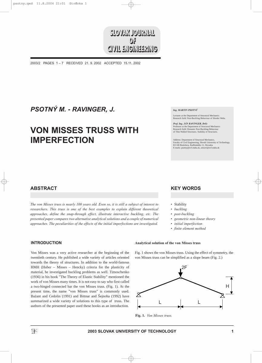
Fig. 1 shows the von Misses truss. Using the effect of symmetry, thevon Misses truss can be simplified as a slope beam (Fig. 2.)
L L
H
2F
Fig. 1. Von Misses truss.
psotny.qxd 11.8.2004 21:01 StrÆnka 1
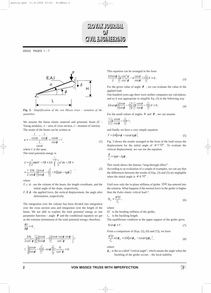
We assume the linear elastic material and prismatic beam (E –Young modulus, A – area of cross section, I – moment of inertia).The strain of the beam can be written as
, (1)
where L is the span.The total potential energy isThe total potential energy is
, (2)
whereV, s, α - are the volume of the beam, the length coordinate, and the
initial angle of the slope, respectively,F, δ, ϕ - the applied force, the vertical displacement, the angle after
deformation, respectively.
The integration over the volume has been divided into integrationover the cross section area and integration over the length of thebeam. We are able to explain the total potential energy as oneparameter function – angle and the conditional equation we getas the extreme (minimum) of the total potential energy; therefore,
,
This equation can be arranged in the form
. (3)
For the given value of angle , we can evaluate the value of theapplied load. One hundred years ago there were neither computers nor calculators,and so it was appropriate to simplify Eq. (3) in the following way
. (4)
For the small values of angles and , we can assume
,
and finally we have a very simple equation
. (5)
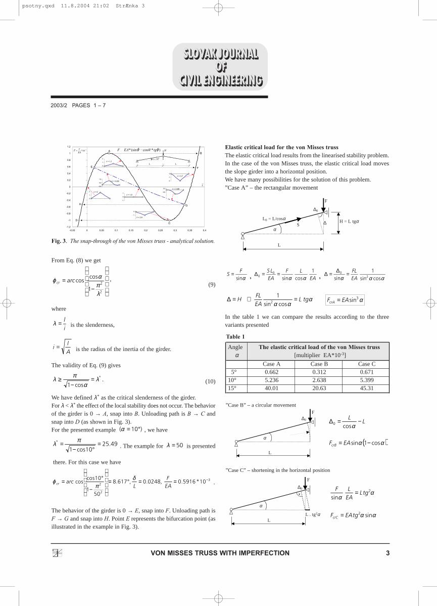
Fig. 3 shows the results arranged in the form of the load versus thedisplacement for the initial angle of . To evaluate thevertical displacement, we can use the equation
.
This result shows the famous ”snap-through effect”. According to an evaluation of a couple of examples, we can say thatthe differences between the results of Eqs. (3) and (5) are negligiblewhen the initial angle is .
Until now only the in-plane stiffness of girder has entered intothe solution. What happens if the normal force in the girder is higherthan the Euler elastic critical load ?
, (6)
whereEI is the bending stiffness of the girder,lcr is the buckling length.The equilibrium condition in the upper support of the girder gives
. (7)
From a comparison of (Eqs. (5), (6) and (7)), we have
, (8)
whereϕcr is the so-called ”critical angle”, which means the angle when the
buckling of the girder occurs – the local stability.
( )crcrcrcr
tgEAl
EI ϕαϕϕπcossinsin2
2
−=
FN =ϕsin
2
2
crcr l
EIN
π=
)(EA
°≤ 10α
ϕαδtgtg
L−=
°= 10α
( )ϕαϕ tgEAF cossin −=
11coscos
321 =
− &
ϕα
ϕα
01coscos
321
1coscos
sin =+
−
− FEA
ϕα
ϕαϕ
ϕ
01coscos
4coscos
32sin
2
2
=+
+− F
EAϕα
ϕαϕ
( ) 0cos
sin1coscos
cossincoscos
1coscos
2cos2
2
2
22
=+
−
−+
+
−
ϕϕ
ϕα
ϕϕϕα
ϕα
ϕ
FL
EAL
0=∂∂ϕU
ϕ
( )ϕαϕα
ϕ
δεδσεϕ
tgtgFLEAL
FdsEAFdVU
L
V
−−
−=
=−=−= ∫∫2
cos
0
2
1coscos
cos21
21
21
1coscos
cos
coscos −=−
−=ϕα
α
ϕαεL
LL
2003/2 PAGES 1 � 7
2 VON MISSES TRUSS WITH IMPERFECTION
äH
F
á
ö
E,A,I
Fig. 2. Simplification of the von Misses truss � notation of thequantities.
α
ϕ
δ
L
psotny.qxd 11.8.2004 21:01 StrÆnka 2
From Eq. (8) we get
,(9)
where
is the slenderness,
is the radius of the inertia of the girder.
The validity of Eq. (9) gives
. (10)
We have defined λ* as the critical slenderness of the girder.For λ < λ* the effect of the local stability does not occur. The behaviorof the girder is 0 → A, snap into B. Unloading path is B → C andsnap into D (as shown in Fig. 3).For the presented example , we have
. The example for is presented
there. For this case we have
.
The behavior of the girder is 0 → E, snap into F. Unloading path isF → G and snap into H. Point E represents the bifurcation point (asillustrated in the example in Fig. 3).
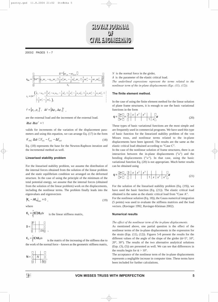
Elastic critical load for the von Misses trussThe elastic critical load results from the linearised stability problem.In the case of the von Misses truss, the elastic critical load movesthe slope girder into a horizontal position.We have many possibilities for the solution of this problem.”Case A” – the rectangular movement
, ,
In the table 1 we can compare the results according to the threevariants presented
α3sinEAFcrA =ααα
tgLEAFL
H =⇒=∆cossin
12
ααα cossin1
sin 20
EAFL=∆=∆
EALF
EALS 1
cossin0
0 αα==∆
αsinF
S =
3
2
210*5916.0,0248.0,617.8
501
10coscos −==°=
−
°=EAF
Larccr
δπ
ϕ
50=λ49.2510cos1
* =°−
= πλ
)10( °=α
*
cos1λ
απλ =
−≥
AI
i =
il=λ
−=
2
2
1
coscos
λπαϕ arccr
2003/2 PAGES 1 � 7
3VON MISSES TRUSS WITH IMPERFECTION
Fig. 3. The snap-through of the von Misses truss - analytical solution.
( )αα
α
cos1sin
cos0
−=
−=∆
EAF
LL
crB
αα
αα
sin
sin
2
2
tgEAF
tgLEALF
crC =
=
”Case B” – a circular movement
”Case C” – shortening in the horizontal position
L0 = L/cosαH = L tgα
L
L
LL . tg2α
F
F
F
Sα
α
α
∆
∆0
∆0
∆0
ϕ � ϕα
Angle The elastic critical load of the von Misses trussα [multiplier EA*10-3]
Case A Case B Case C5° 0.662 0.312 0.671
10° 5.236 2.638 5.39915° 40.01 20.63 45.31
Table 1
psotny.qxd 11.8.2004 21:02 StrÆnka 3

Significant differences between case B and cases A and C have beenobtained. The elastic critical load is unrealistically high compared tothe top of the curve represented in the nonlinear solution and thesnap-through effect (Fig. 3).
Numerical solution of the geometrically nonlinear problems
For the solution of the von Misses truss, the geometrically nonlineartheory must be used. In the analytical solution presented in theprevious part of this article, the geometrically nonlinear solutionwas satisfied by evaluating the strain (Eq. (1)) and the total potentialenergy (Eq. (2)) on the deformed shape of the truss. If we want toarrange the general solution (for example, the finite elementmethod), we must take into consideration the nonlinear terms in theevaluation of the strain (Fig. 4).
Fig. 4. Part of the girder., (11)
whereu is a function of the displacement in the direction of the axis of
the girder – in-plane displacements,w is the function of the displacement perpendicular to the axis of
the girder – the bending displacements, z is the thickness coordinate, and
the indexes denote the derivations.
The bending displacements are much bigger than the in-planedisplacements ; we can therefore ignore the in-planenonlinear term (underlined in Eq. (11)), and the strain is reduced to
(12)
In the case of the von Misses girder, in-plane displacements can playa crucial role. The effect of the in-plane nonlinear term is a partialproblem investigated in the presented article.
We assume the linear elastic material and the stresses are:
, (13)
the index ”0” represents the initial strain.
For a nonlinear solution as a combination of the incremental anditerative steps, we have noted the vectors and the increments of thedisplacements as
, . (14)
The increment of the strain is
. (15)
The underlined expressions represent the terms related to thenonlinear term of the in-plane displacements (Eqs. (11),(12))We arrange the variations of the increments of the strain as follows:
.(16)
From the condition of the minimum of the increment of the totalpotential energy, we have the conditional equations (Ravinger – 1994)
,
, , (17)
wherea is the length of the girder
,
α is the vector of the variational constants – the displacementparameters
,
,.21
21
21
23
31*
,21
23
21
21
*
2,0
2,
2,0
2,,0,33
2,0
2,
2,0
2,,0,22
−+−−+=
−+−+−=
xxxxxx
xxxxxx
wwuuuuEAd
wwuuuuEAd
( )( )
+
+=
33,,,
22
,,,
*
*
dwuwEA
d
wuwEAEI
xxx
xxx
IINNCCDD
[ ] [ ] αα 1,,, ,,,, BuwwBuwq Txxxx
T ===
( ) ( )( )∫ =∆+−+∆∆a
TTINC
TT dxffBsBBDB0
int111 0ααδ
0)( =∆Uδ
xxxxxx
xxxxx
wzwwww
uuuuu
,,,,,
,,,,,
∆−∆∆+∆+
+∆∆+∆+∆=∆
δδδ
δδδεδ
xxxxxxxxx wzwwwuuuu ,2,,,
2,,,, 2
121 ∆−∆+∆+∆+∆+∆=∆ε
[ ]Tuw ∆∆=∆ ,qq[ ]Tuw,=qq
( )0εεσ −= E
xxxx wzwu ,2,, 2
1 −+=ε
uw >>
xxxxx wzwuu ,2,
2,, 2
121 −++=ε
2003/2 PAGES 1 � 7
4 VON MISSES TRUSS WITH IMPERFECTION
Fig. 4. Part of the girder.
pz
pxx
uw
E, A, I
a
z
psotny.qxd 11.8.2004 21:02 StrÆnka 4
,
are the external load and the increment of the external load.
valids for increments of the variation of the displacement para-meters and using this equation, we can arrange Eq. (17) in the form
(18)
Eq. (18) represents the base for the Newton-Raphson iteration andthe incremental method as well.
Linearised stability problem
For the linearised stability problem, we assume the distribution ofthe internal forces obtained from the solution of the linear problemand the static equilibrium condition we arranged on the deformedstructure. In the case of using the principle of the minimum of thetotal potential energy, we assume that the internal forces (obtainedfrom the solution of the linear problem) work on the displacements,including the nonlinear terms. The problem finally leads into theeigenvalues and eigenvectors
, (19)
where
is the linear stiffness matrix,
,
is the matrix of the increasing of the stiffness due tothe work of the normal force – known as the geometric stiffness matrix,
,
N is the normal force in the girder,λ is the parameter of the elastic critical load.The underlined expressions represent the terms related to thenonlinear term of the in-plane displacements (Eqs. (11), (12)).
The finite element method.
In the case of using the finite element method for the linear solutionof plane frame structures, it is enough to use the basic variationalfunctions in the form
(20)
These types of basic variational functions are the most simple andare frequently used in commercial programs. We have used this typeof basic function for the linearized stability problem of the vonMisses truss, and nonlinear terms related to the in-planedisplacements have been ignored. The results are the same as theelastic critical load obtained according to ”Case C”.In the case of the nonlinear solution of frame structures, there is aninteraction between the in-plane displacements (”u”) and thebending displacements (”w”). In that case, using the basicvariational function Eq. (20) is not appropriate. Much better resultscan be obtained using
(21)
For the solution of the linearised stability problem (Eq. (19)), wehave used the basic function (Eq. (21)). The elastic critical loadobtained is the same as the elastic critical load from ”Case A”.For the nonlinear solution (Eq. 18)), the Gauss numerical integration(5 points) was used to evaluate the stiffness matrices and the loadvectors. (Ravinger 1992, Ravinger-Kleiman 2002).
Numerical results
The effect of the nonlinear term of the in-plane displacements.As mentioned above, one partial question is the effect of thenonlinear terms of the in-plane displacements in the expression forthe strain (Eqs. (11), (12)). Figures 5-8 present the results for thedifferent values of the angle of the slope of the girder (α=5°, 10°,20°, 30°). The results of the two alternative analytical solutions(Eqs. (3), (5)) are presented as well. We can see that differences inthe results begin for α > 10°. The acceptance of the nonlinear term of the in-plane displacementsrepresents a negligible increase in computer time. These terms havebeen included for further calculations.
α
=
=32
32
1
1
xxx
xxxu
wqq
α
=
=x
xxxu
w
1
1 32
=
N
NNN
∫=a
TG dx
01 11NNBBBBKK
=
EA
EI
DD
∫=a
T dx0
1 11LL DDBBBBKK
0det
=− GGLL KKKK λ
int ∆−−+∆ extextINC fffK α
1=∆∆ Tαδαδ
[ ] [ ]TxzT
xz ppfppf ∆∆=∆= ,,,
.
2
1
2
1
2
1
2
1
2
1
2
1
2
1
2
3
*2,0
2,
2,0,
2,,
2,0,
3,
2,0,0,
2,,0,
3
−+
+−+−+−−+−=
xx
xxxxxxxxxxxxx
ww
wuwuuuuuuuuuuEAs
( )
−+−+−
−
=
3
2,0,
3,,
2,0,
2,,,0,,
,0,
21
21
21
21
*
*
s
wwwwuwuwuwuEA
wwEI
xxxxxxxxxxx
xxxx
iinnttss
2003/2 PAGES 1 � 7
5VON MISSES TRUSS WITH IMPERFECTION
αα
αα
(
).
psotny.qxd 11.8.2004 21:02 StrÆnka 5

2003/2 PAGES 1 � 7
6 VON MISSES TRUSS WITH IMPERFECTION
Fig. 5. Comparison of the theoretical and numerical results forangle α =5°
Fig. 6 Comparison of the theoretical and numerical results forangle α =10°
Fig. 7. Comparison of the theoretical and numerical results forangle α =20°
Fig. 8. Comparison of the theoretical and numerical results forangle α =30°
Fig. 9. The elastic critical load and the modes of buckling.
Fig. 10. The von Misses truss with an imperfection � a smallbending stiffness of the beam.
α
α
αα
α
psotny.qxd 11.8.2004 21:02 StrÆnka 6

The von Misses truss with imperfections.At the present time the theoretical models for the evaluation of theultimate load assume a structure with imperfections. From thesolution of the linearised stability problem, we can get the elasticcritical load and the modes of the buckling. In the case of the vonMisses truss, the girder remains straight in one mode. The othermodes are the same as the modes of the buckling of the simplesupported girder (Fig. 9). The first mode of the buckling has beenused as the mode of the initial imperfection (Figs. 10, 11). Theload–displacement curve was obtained from the solution of Eq. (18),taking the displacement as the pivotal term of the Newton-Raphsoniteration. For the stable branch the incremental stiffness matrix
must be positively defined; all minors must be positive as well;
and the incremental stiffness matrix must be evaluated for the loadas the pivotal term. The primary and secondary branches have beenevaluated. Other branches have not been investigated. Fig. 10 shows an example when the elastic critical load is lower thanthe top of the load-displacement curve of the ideal von Misses truss.Even in the case when the elastic critical load is bigger than themaximum load of the ideal von Misses truss (Fig. 11), the top of theload- displacement curve of the von Misses truss with animperfection is much lower than the maximum load of the ideal vonMisses truss. Both results show the crucial role of imperfection inthe behavior of the von Misses truss.
CONCLUSION
The presented results show that in the in-plane non-linear term ofthe strain, (Eq. (11)) has a small effect on the solution of the vonMisses truss with the angle . On the other hand, theacceptance of this term into the solution does not increase thecomputer effort. In any case of the von Misses truss, the ultimate load is lower than thetop of the load- displacement curve of the ideal truss. The bendingstiffness and imperfection play crucial roles in the behavior of the truss.
ACKNOWLEDGEMENTS
The presented results have been achieved due to research supportedby the Slovak Scientific Grant Agency.
°≤ 10α
IINNCCKK
2003/2 PAGES 1 � 7
7VON MISSES TRUSS WITH IMPERFECTION
Fig. 11. The von Misses truss with an imperfection � a largerbending stiffness of the beam.
REFERENCES
• BA�ANT, Z. � CEDOLIN, L. (1991), Stability of Structures.Oxford University Press. Oxford.
• BITTNAR, Z. � �EJNOHA, J. (1992), Numerical Methods inMechanics II. Vydavatelství ÈVUT Prague.
• MURÍN, J. � KUTI�, V. (2001), Solution of Non-IncrementalFEM Equations of a Non-Linear Continuum. Strojnícky èasopis,52, No 6, 360-371.
• RAVINGER, J. (1992), �Dynamic Post-Buckling Behaviour ofPlate Girders�, J. of Constructional Steel Research. 21, 1-3,195-204.
• RAVINGER, J. (1994), �Vibration of an Imperfect Thin-WalledPanel. Part 1: Theory and Illustrative Examples. Part 2:Numerical Results and Experiment”, Thin-Walled Structures 19,1-36.
• RAVINGER, J. � KLEIMAN, P. (2002), �Natural Vibration ofImperfect Columns and Frames�, Building Research Journal Vol.50, No 1 , 49-67.
• TIMOSCHENKO, S.P. (1936). Theory of elastic stability.McGraw-Hill, New York.
psotny.qxd 11.8.2004 21:02 StrÆnka 7