wireless sniffing with wireshark - will hack for
TRANSCRIPT
6:1
Wireless Sniffingwith Wireshark
Solutions in this chapter:
■ Techniques for Effective Wireless Sniffing
■ Understanding Wireless Card OperatingModes
■ Configuring Linux for Wireless Sniffing
■ Configuring Windows for Wireless Sniffing
■ Using Wireless Protocol Dissectors
■ Useful Wireless Display Filters
■ Leveraging Wireshark Wireless AnalysisFeatures
Chapter 6
� Summary
� Solutions Fast Track
� Frequently Asked Questions
ethereal_ch06.qxd 11/8/06 5:07 PM Page 1
IntroductionWireless networking is a complex field. With countless standards, protocols, andimplementations, it is not uncommon for administrators to encounter configurationissues that require sophisticated troubleshooting and analysis mechanisms.
Fortunately, Wireshark has sophisticated wireless protocol analysis support tohelp administrators troubleshoot wireless networks. With the appropriate driver sup-port, Wireshark can capture traffic “from the air” and decode it into a format thathelps administrators track down issues that are causing poor performance, intermit-tent connectivity, and other common problems.
Wireshark is also a powerful wireless security analysis tool. Using Wireshark’sdisplay filtering and protocol decoders, you can easily sift through large amounts ofwireless traffic to identify security vulnerabilities in the wireless network, includingweak encryption or authentication mechanisms, and information disclosure risks.Youcan also perform intrusion detection analysis to identify common attacks againstwireless networks while performing signal strength analysis to identify the locationof a station or access point (AP).
This chapter introduces the unique challenges and recommendations for trafficsniffing on wireless networks. We examine the different operating modes supportedby wireless cards, and configure Linux and Windows systems to support wirelesstraffic capture and analysis using Wireshark and third-party tools. Once you have mas-tered the task of capturing wireless traffic, you will learn how to leverage Wireshark’spowerful wireless analysis features, and learn how to apply your new skills.
Challenges of Sniffing WirelessTraditional network sniffing on an Ethernet network is fairly easy to set up. In a sharedenvironment, an analysis workstation running Wireshark starts a new packet capture,which configures the card in promiscuous mode and waits until the desired amount oftraffic has been captured. In a switched environment, you need to configure a span portthat mirrors the traffic sent to other stations, before initiating the packet capture.
In both of these cases, it is easy to initiate a packet capture and start collectingtraffic for analysis. When you switch to wireless analysis, however, the process oftraffic sniffing becomes more complicated and requires additional decisions up frontto best support the analysis you want to perform.
Selecting a Static ChannelWhere a wired network offers a single medium mechanism for packet capture (i.e.,the wire), wireless networks can operate on multiple wireless channels using different
www.syngress.com
6:2 Chapter 6 • Wireless Sniffing with Wireshark
ethereal_ch06.qxd 11/8/06 5:07 PM Page 2
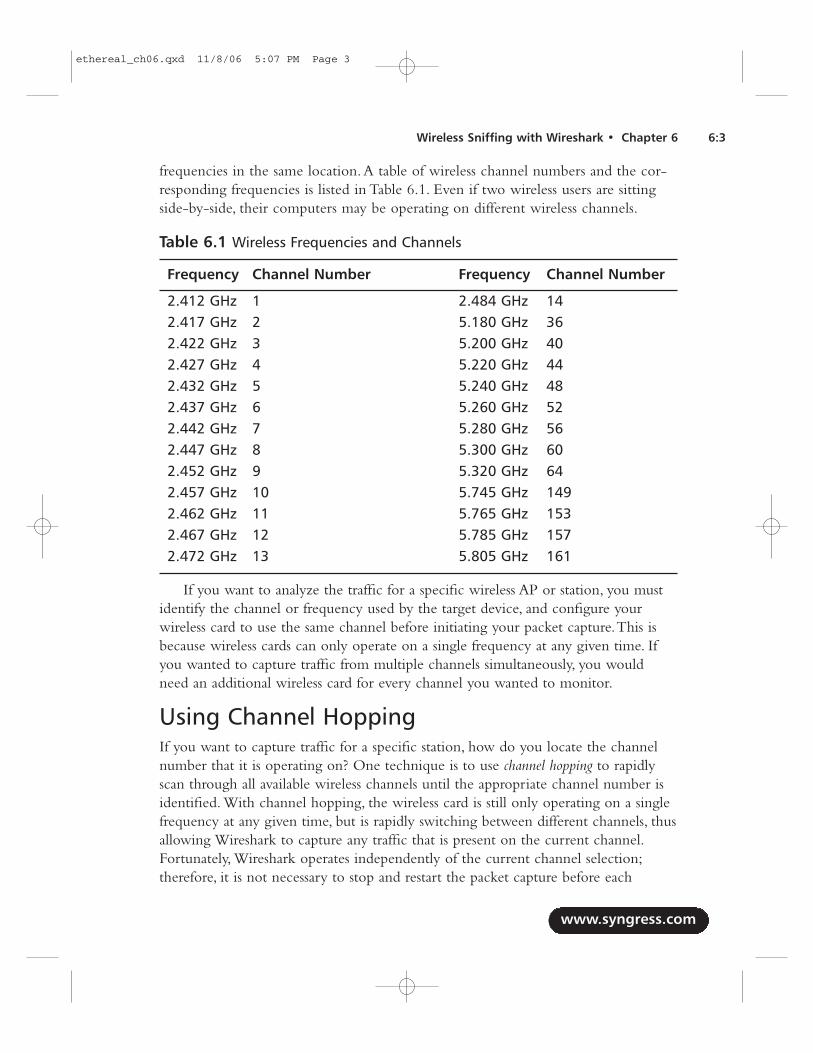
frequencies in the same location.A table of wireless channel numbers and the cor-responding frequencies is listed in Table 6.1. Even if two wireless users are sittingside-by-side, their computers may be operating on different wireless channels.
Table 6.1 Wireless Frequencies and Channels
Frequency Channel Number Frequency Channel Number
2.412 GHz 1 2.484 GHz 142.417 GHz 2 5.180 GHz 362.422 GHz 3 5.200 GHz 402.427 GHz 4 5.220 GHz 442.432 GHz 5 5.240 GHz 482.437 GHz 6 5.260 GHz 522.442 GHz 7 5.280 GHz 562.447 GHz 8 5.300 GHz 602.452 GHz 9 5.320 GHz 642.457 GHz 10 5.745 GHz 1492.462 GHz 11 5.765 GHz 1532.467 GHz 12 5.785 GHz 1572.472 GHz 13 5.805 GHz 161
If you want to analyze the traffic for a specific wireless AP or station, you mustidentify the channel or frequency used by the target device, and configure yourwireless card to use the same channel before initiating your packet capture.This isbecause wireless cards can only operate on a single frequency at any given time. Ifyou wanted to capture traffic from multiple channels simultaneously, you wouldneed an additional wireless card for every channel you wanted to monitor.
Using Channel HoppingIf you want to capture traffic for a specific station, how do you locate the channelnumber that it is operating on? One technique is to use channel hopping to rapidlyscan through all available wireless channels until the appropriate channel number isidentified. With channel hopping, the wireless card is still only operating on a singlefrequency at any given time, but is rapidly switching between different channels, thusallowing Wireshark to capture any traffic that is present on the current channel.Fortunately, Wireshark operates independently of the current channel selection;therefore, it is not necessary to stop and restart the packet capture before each
www.syngress.com
Wireless Sniffing with Wireshark • Chapter 6 6:3
ethereal_ch06.qxd 11/8/06 5:07 PM Page 3
channel hop. Change to the desired channel while Wireshark is running andWireshark will continue to collect traffic.
Unfortunately, you cannot rely on channel hopping for all of your wireless trafficsniffing needs. Channel hopping will cause you to lose traffic, because you arerapidly switching channels. If your wireless card is configured to operate on channel11 and you hop to another channel, you will not be able to “hear” any traffic that isoccurring on channel 11 until you return as part of the channel-hopping pattern.Asa result, channel hopping is not a useful technique for analyzing traffic for a specificAP or station, but it can be useful to identify the channel the network is operatingon, which can be used to set a static channel assignment.
Range in Wireless NetworksAnother unique characteristic of Wireshark is the range between the capture stationand the transmitting device(s). When capturing wireless traffic, the range betweenthe capture station and the transmitter is significant, and must be accounted for toprovide the most reliable traffic collection.
If the capture station is too far away from one or more transmitters, it is unableto “hear” the wireless traffic. If the capture station is too close to another transmit-ting station, the radio interface may become overwhelmed with too much signal,thus resulting in corrupted traffic. Placing the station near the transmitter no closerthan 3 feet is the most desirable location for achieving optimal traffic capture.Youcan achieve satisfactory results for a wireless packet capture from further away, butyou will lose traffic from the capture if there is a significant distance between thecapture station and the transmitter(s).
Interference and CollisionsAnother challenge of sniffing wireless networks is the risk of interference and lostpackets. Unlike an Ethernet network that can transmit and monitor the networksimultaneously, wireless cards can only receive or transmit asynchronously.As a result,wireless networks must take special precautions to prevent multiple stations fromtransmitting at the same time. While these collision-avoidance mechanisms workwell, it is still possible to experience collisions between multiple transmitters on thesame channel, or to experience collisions with wireless local area networks (LANs)and other devices using the same frequency (e.g., cordless phones, baby monitors,microwave ovens, and so on).
When two devices transmit simultaneously within range of the sniffing station, thetransmission becomes corrupted and is rejected by the receiver as an invalid packet.After waiting random back-off intervals, the two stations repeat their transmission, thus
www.syngress.com
6:4 Chapter 6 • Wireless Sniffing with Wireshark
ethereal_ch06.qxd 11/8/06 5:07 PM Page 4
indicating they are attempting to transmit the same information again.This is normalactivity in a wireless LAN, but presents a challenge to the sniffing station.
When capturing traffic on a wireless network, there is no guarantee that youcaptured 100 percent of the traffic. Some traffic may have become corrupted intransit. In other cases, your capture station may be positioned such that it receivesvalid frames before they become corrupt en-route to the destination host.This forcesthe transmitting station to re-transmit the corrupted packets, which causes the cap-ture station to have multiple copies of the same packet in the capture.
Recommendations for Sniffing WirelessNow that you understand some of the limitations and challenges in sniffing wirelessnetworks, you can apply some recommendations to achieve the best fidelity in wire-less packet captures:
■ Locate the Capture Station Near the Source When initiating apacket capture, locate the capture station close to the source of the wirelessactivity you are interested in (i.e., an AP or a wireless station).
■ Disable Other Nearby Transmitters If you are using an external wire-less card (e.g., a Personal Computer Emulator Card [PCCard]) for sniffingtraffic, and you have a built-in card in your laptop, it is common to experi-ence lost traffic on the sniffing card due to interference from the built-incard.To eliminate this factor and achieve a more accurate packet capture,disable any built-in wireless transmitters on the capture station during thepacket capture, including Institute of Electrical & Electronics Engineers(IEEE) 802.11 interfaces and Bluetooth devices.
■ Reduce CPU Utilization While Capturing If your host experiencesexcessive central processing unit (CPU) utilization during a packet capture,you may experience packet loss in the wireless capture (e.g., it is not agood idea to burn a DVD while capturing wireless traffic).To preventpacket loss, try to reduce your CPU utilization when capturing traffic withany sniffer software.
■ Match Channel Selection If you take a comprehensive packet capture ofa wireless network, make sure your wireless card is sniffing on the samechannel as the target network. If you are channel hopping during a packetcapture, you will inevitably lose traffic from your target network. Only usechannel hopping to discover the available networks; focus your capture on asingle channel. Note that while you may capture some traffic from a nearby
www.syngress.com
Wireless Sniffing with Wireshark • Chapter 6 6:5
ethereal_ch06.qxd 11/8/06 5:07 PM Page 5
channel (e.g., you see traffic from channels 1 and 6 when listening onchannel 3), the captured traffic will be sporadic and incomplete.
■ Match Modulation Type With the progression of different IEEE 802.11Physical layer standards, different modulation mechanisms have been devel-oped to accommodate faster data rates. Ensure the supported modulationmechanism for your wireless card matches the target network you are tar-geting. For example, an IEEE 802.11b wireless card sniffing an IEEE802.11g network will capture some backward-compatible modulatedtraffic, but may miss other traffic modulated for an 802.11g network. If indoubt, ensure the card you are using for traffic capture supports all the stan-dard modulation mechanisms. Currently, this includes an IEEE 802.11a/b/gcard, but will also include IEEE 802.11n cards with MIMO (multipleinput, multiple output) technology in the future.
Understanding Wireless Card ModesBefore we start wireless sniffing using Wireshark, it is helpful to understand the dif-ferent operating modes supported by wireless cards. Most wireless users only usetheir wireless cards as a station to an AP. In managed mode, the wireless card anddriver software rely on a local AP to provide connectivity to the wireless network.
Another common mode for wireless cards is ad-hoc mode (or Independent BasicService Set [IBSS] mode.Two wireless stations that want to communicate with eachother directly can do so by sharing the responsibilities of an AP for a limited subsetof wireless LAN services.Ad-hoc mode is used for short-term connectivity betweenstations, when an AP is not available to provide connectivity.
Many wireless cards also support master mode, where the wireless card providesthe services of an AP when paired with the appropriate software. Managed modeallows you to configure your laptop or desktop system as an AP for providing con-nectivity to other wireless stations.
Finally, wireless cards support monitor mode functionality.When configured in mon-itor mode, the wireless card stops transmitting data and sniffs the currently configuredchannel, reporting the contents of any observed packets to the host operating system.This is the most useful mode of operation for analysis when using Wireshark, becausea wireless card configured in monitor mode reports the entire contents of wirelesspackets, including header information and the encrypted or unencrypted data con-tents.When in monitor mode, the wireless card and driver reports the wireless frames“as-is,” giving the most accurate view of the wireless activity for the selected channel.
www.syngress.com
6:6 Chapter 6 • Wireless Sniffing with Wireshark
ethereal_ch06.qxd 11/8/06 5:07 PM Page 6
In order to analyze a wireless network effectively using Wireshark, you needto configure your wireless card to operate in monitor mode on the appropriatechannel, and then start a packet capture. Unfortunately, this is easier said thandone. Because the majority of wireless card users use their wireless cards in man-aged or ad-hoc mode, wireless driver developers may not include support formonitor mode access. In the case of Linux, many drivers support monitor mode.Those Linux drivers that do not natively support monitor mode are often“patched” by other interested users or developers in order to access monitormode functionality. However, in the case of Windows, drivers are closed-source,which prevents anyone except the driver developer from supplying monitor modefunctionality. However, some commercial options exist for Windows that allowyou to leverage the monitor mode support in your wireless card with customdriver software.
Next, we examine the steps necessary to configure your wireless card to supportmonitor mode access on Linux and Windows systems.
Getting Support for Monitor Mode -LinuxIn order to begin sniffing wireless traffic with Wireshark, your wireless card must bein monitor mode. Wireshark does not do this automatically; you have to manuallyconfigure your wireless card before starting your packet capture. However, the com-mands you need in order to configure the card in monitor mode can differ basedon the type of wireless card and driver that you are using.This section discusseshow to complete this step based on the most common wireless card and drivercombination for Linux.
TIP
Determining the type of wireless card you have isn’t always easy. Whilethere are only a handful of manufacturers that make the wirelesschipset hardware, multiple vendors re-brand the cards, thus making itdifficult to identify what the actual chipset is. One resource for identi-fying the chipset from the card manufacturer is available atwww.linux-wless.passys.nl. If your specific card isn’t listed here you cansearch using Google with the card name and keyword “chipset” (e.g.,WPC55AG chipset).
www.syngress.com
Wireless Sniffing with Wireshark • Chapter 6 6:7
ethereal_ch06.qxd 11/8/06 5:07 PM Page 7
Linux Wireless Extensions Compatible DriversMost wireless drivers for Linux systems use the Linux Wireless Extensions interface,thus providing a consistent configuration interface for manipulating the wirelesscard. First, let’s identify the wireless driver interface name by running the wirelesscard configuration utility iwconfig with no parameters:
$ iwconfig
eth0 no wireless extensions.
lo no wireless extensions.
eth1 IEEE 802.11b ESSID:"Beacon Wi-Fi Network"
Mode:Managed Frequency:2.462 GHz Access Point: 00:02:2D:8B:70:2E
Bit Rate:11 Mb/s Tx-Power=20 dBm Sensitivity=8/0
Retry limit:7 RTS thr:off Fragment thr:off
Power Management:off
Link Quality=50/100 Signal level=-71 dBm Noise level=-86 dBm
Rx invalid nwid:0 Rx invalid crypt:0 Rx invalid frag:0
Tx excessive retries:0 Invalid misc:286 Missed beacon:5
NOTE
It is recommended that users take advantage of the Linux 2.6 kernelwhenever possible. Most Linux distributions install their wireless toolspackages for iwconfig and iwpriv by default; you will need to installthese tools manually if they are not included with your default distribu-tion. Use the package management utilities that come with your Linuxdistribution to search for packages with the name “wireless-tools” toidentify installation options. Information specific to older Debian, SuSE,RedHat, and Mandrake distributions is available atwww.hpl.hp.com/personal/Jean_Tourrilhes/Linux/DISTRIBUTIONS.txt.
From this output, we determine that interfaces eth0 and lo do not support LinuxWireless Extensions; however, Interface eth1 does support wireless extensions. Fromthe output, we can see that the card is currently in managed mode and is associatedwith an IEEE 802.11b network with the Service Set Identifier (SSID) “Beacon Wi-FiNetwork” at 2.462 GHz (channel 11).
www.syngress.com
6:8 Chapter 6 • Wireless Sniffing with Wireshark
ethereal_ch06.qxd 11/8/06 5:07 PM Page 8
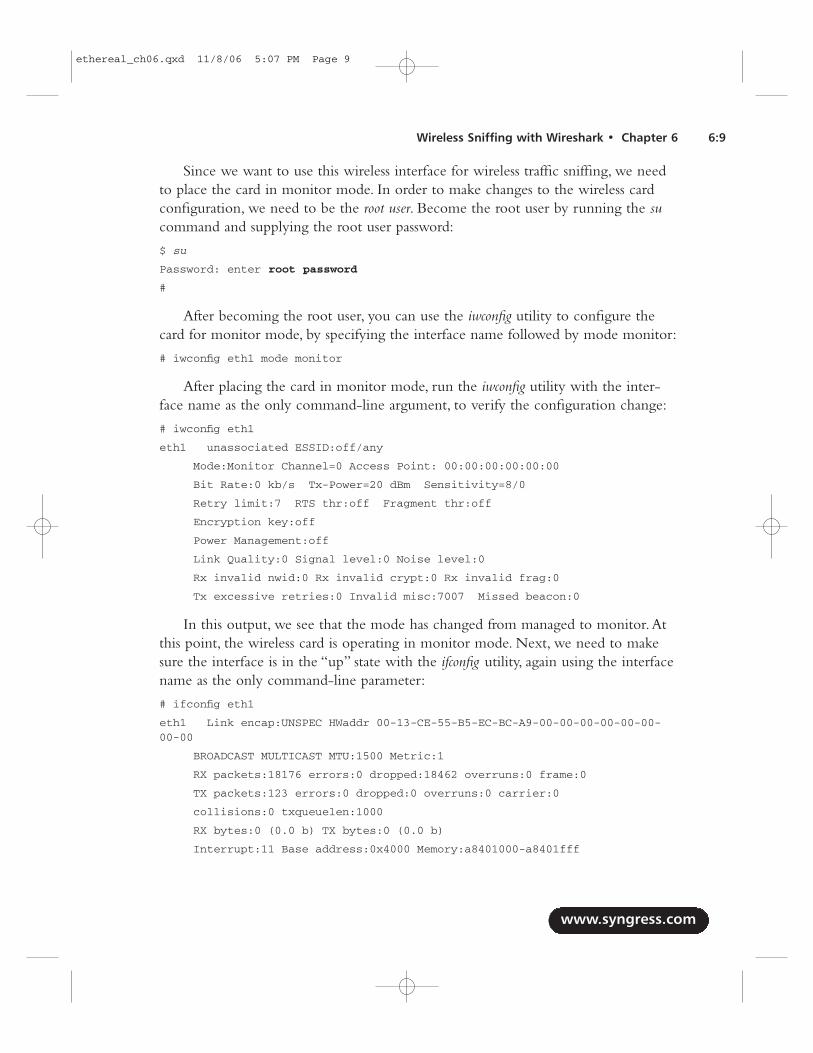
Since we want to use this wireless interface for wireless traffic sniffing, we needto place the card in monitor mode. In order to make changes to the wireless cardconfiguration, we need to be the root user. Become the root user by running the sucommand and supplying the root user password:
$ su
Password: enter root password
#
After becoming the root user, you can use the iwconfig utility to configure thecard for monitor mode, by specifying the interface name followed by mode monitor:
# iwconfig eth1 mode monitor
After placing the card in monitor mode, run the iwconfig utility with the inter-face name as the only command-line argument, to verify the configuration change:
# iwconfig eth1
eth1 unassociated ESSID:off/any
Mode:Monitor Channel=0 Access Point: 00:00:00:00:00:00
Bit Rate:0 kb/s Tx-Power=20 dBm Sensitivity=8/0
Retry limit:7 RTS thr:off Fragment thr:off
Encryption key:off
Power Management:off
Link Quality:0 Signal level:0 Noise level:0
Rx invalid nwid:0 Rx invalid crypt:0 Rx invalid frag:0
Tx excessive retries:0 Invalid misc:7007 Missed beacon:0
In this output, we see that the mode has changed from managed to monitor.Atthis point, the wireless card is operating in monitor mode. Next, we need to makesure the interface is in the “up” state with the ifconfig utility, again using the interfacename as the only command-line parameter:
# ifconfig eth1
eth1 Link encap:UNSPEC HWaddr 00-13-CE-55-B5-EC-BC-A9-00-00-00-00-00-00-00-00
BROADCAST MULTICAST MTU:1500 Metric:1
RX packets:18176 errors:0 dropped:18462 overruns:0 frame:0
TX packets:123 errors:0 dropped:0 overruns:0 carrier:0
collisions:0 txqueuelen:1000
RX bytes:0 (0.0 b) TX bytes:0 (0.0 b)
Interrupt:11 Base address:0x4000 Memory:a8401000-a8401fff
www.syngress.com
Wireless Sniffing with Wireshark • Chapter 6 6:9
ethereal_ch06.qxd 11/8/06 5:07 PM Page 9
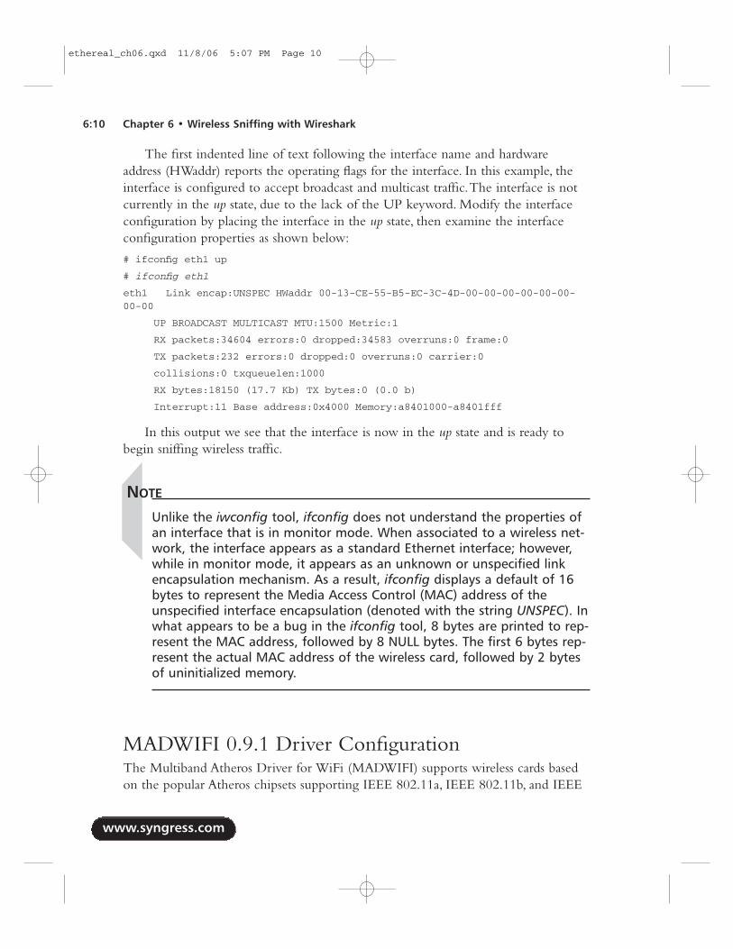
The first indented line of text following the interface name and hardwareaddress (HWaddr) reports the operating flags for the interface. In this example, theinterface is configured to accept broadcast and multicast traffic.The interface is notcurrently in the up state, due to the lack of the UP keyword. Modify the interfaceconfiguration by placing the interface in the up state, then examine the interfaceconfiguration properties as shown below:
# ifconfig eth1 up
# ifconfig eth1
eth1 Link encap:UNSPEC HWaddr 00-13-CE-55-B5-EC-3C-4D-00-00-00-00-00-00-00-00
UP BROADCAST MULTICAST MTU:1500 Metric:1
RX packets:34604 errors:0 dropped:34583 overruns:0 frame:0
TX packets:232 errors:0 dropped:0 overruns:0 carrier:0
collisions:0 txqueuelen:1000
RX bytes:18150 (17.7 Kb) TX bytes:0 (0.0 b)
Interrupt:11 Base address:0x4000 Memory:a8401000-a8401fff
In this output we see that the interface is now in the up state and is ready tobegin sniffing wireless traffic.
NOTE
Unlike the iwconfig tool, ifconfig does not understand the properties ofan interface that is in monitor mode. When associated to a wireless net-work, the interface appears as a standard Ethernet interface; however,while in monitor mode, it appears as an unknown or unspecified linkencapsulation mechanism. As a result, ifconfig displays a default of 16bytes to represent the Media Access Control (MAC) address of theunspecified interface encapsulation (denoted with the string UNSPEC). Inwhat appears to be a bug in the ifconfig tool, 8 bytes are printed to rep-resent the MAC address, followed by 8 NULL bytes. The first 6 bytes rep-resent the actual MAC address of the wireless card, followed by 2 bytesof uninitialized memory.
MADWIFI 0.9.1 Driver ConfigurationThe Multiband Atheros Driver for WiFi (MADWIFI) supports wireless cards basedon the popular Atheros chipsets supporting IEEE 802.11a, IEEE 802.11b, and IEEE
www.syngress.com
6:10 Chapter 6 • Wireless Sniffing with Wireshark
ethereal_ch06.qxd 11/8/06 5:07 PM Page 10
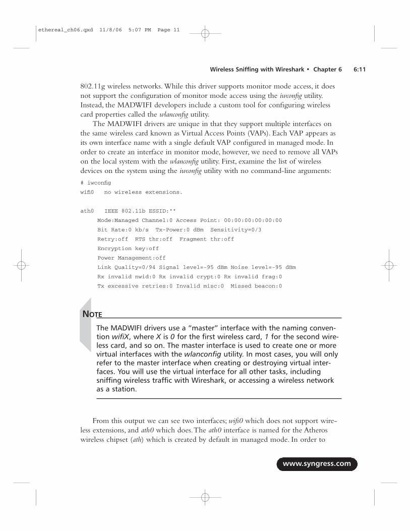
802.11g wireless networks. While this driver supports monitor mode access, it doesnot support the configuration of monitor mode access using the iwconfig utility.Instead, the MADWIFI developers include a custom tool for configuring wirelesscard properties called the wlanconfig utility.
The MADWIFI drivers are unique in that they support multiple interfaces onthe same wireless card known as Virtual Access Points (VAPs). Each VAP appears asits own interface name with a single default VAP configured in managed mode. Inorder to create an interface in monitor mode, however, we need to remove all VAPson the local system with the wlanconfig utility. First, examine the list of wirelessdevices on the system using the iwconfig utility with no command-line arguments:
# iwconfig
wifi0 no wireless extensions.
ath0 IEEE 802.11b ESSID:""
Mode:Managed Channel:0 Access Point: 00:00:00:00:00:00
Bit Rate:0 kb/s Tx-Power:0 dBm Sensitivity=0/3
Retry:off RTS thr:off Fragment thr:off
Encryption key:off
Power Management:off
Link Quality=0/94 Signal level=-95 dBm Noise level=-95 dBm
Rx invalid nwid:0 Rx invalid crypt:0 Rx invalid frag:0
Tx excessive retries:0 Invalid misc:0 Missed beacon:0
NOTE
The MADWIFI drivers use a “master” interface with the naming conven-tion wifiX, where X is 0 for the first wireless card, 1 for the second wire-less card, and so on. The master interface is used to create one or morevirtual interfaces with the wlanconfig utility. In most cases, you will onlyrefer to the master interface when creating or destroying virtual inter-faces. You will use the virtual interface for all other tasks, includingsniffing wireless traffic with Wireshark, or accessing a wireless networkas a station.
From this output we can see two interfaces; wifi0 which does not support wire-less extensions, and ath0 which does.The ath0 interface is named for the Atheroswireless chipset (ath) which is created by default in managed mode. In order to
www.syngress.com
Wireless Sniffing with Wireshark • Chapter 6 6:11
ethereal_ch06.qxd 11/8/06 5:07 PM Page 11
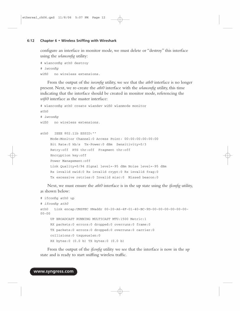
configure an interface in monitor mode, we must delete or “destroy” this interfaceusing the wlanconfig utility:
# wlanconfig ath0 destroy
# iwconfig
wifi0 no wireless extensions.
From the output of the iwconfig utility, we see that the ath0 interface is no longerpresent. Next, we re-create the ath0 interface with the wlanconfig utility, this timeindicating that the interface should be created in monitor mode, referencing thewifi0 interface as the master interface:
# wlanconfig ath0 create wlandev wifi0 wlanmode monitor
ath0
# iwconfig
wifi0 no wireless extensions.
ath0 IEEE 802.11b ESSID:""
Mode:Monitor Channel:0 Access Point: 00:00:00:00:00:00
Bit Rate:0 kb/s Tx-Power:0 dBm Sensitivity=0/3
Retry:off RTS thr:off Fragment thr:off
Encryption key:off
Power Management:off
Link Quality=0/94 Signal level=-95 dBm Noise level=-95 dBm
Rx invalid nwid:0 Rx invalid crypt:0 Rx invalid frag:0
Tx excessive retries:0 Invalid misc:0 Missed beacon:0
Next, we must ensure the ath0 interface is in the up state using the ifconfig utility,as shown below:
# ifconfig ath0 up
# ifconfig ath0
ath0 Link encap:UNSPEC HWaddr 00-20-A6-4F-01-40-BC-9D-00-00-00-00-00-00-00-00
UP BROADCAST RUNNING MULTICAST MTU:1500 Metric:1
RX packets:0 errors:0 dropped:0 overruns:0 frame:0
TX packets:0 errors:0 dropped:0 overruns:0 carrier:0
collisions:0 txqueuelen:0
RX bytes:0 (0.0 b) TX bytes:0 (0.0 b)
From the output of the ifconfig utility we see that the interface is now in the upstate and is ready to start sniffing wireless traffic.
www.syngress.com
6:12 Chapter 6 • Wireless Sniffing with Wireshark
ethereal_ch06.qxd 11/8/06 5:07 PM Page 12
Capturing Wireless Traffic - LinuxOnce your wireless card in Linux has been placed in monitor mode, you are readyto start capturing wireless traffic. Recall that wireless cards can only capture trafficon a single channel at any given time. If you know the wireless channel you want tocapture traffic on, configure your wireless card to listen on that channel using theiwconfig utility:
# iwconfig ath0 channel 1
# iwconfig ath0
Replace ath0 with the name of your wireless interface, and the number 1 withthe channel number you want to capture traffic on.As seen from the output of theiwconfig command, the card is currently configured to listen on 2.412 Gigahertz(GHz) (channel 1).
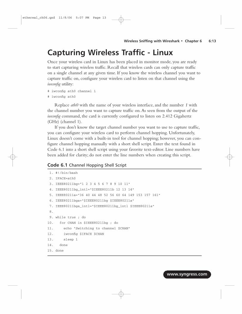
If you don’t know the target channel number you want to use to capture traffic,you can configure your wireless card to perform channel hopping. Unfortunately,Linux doesn’t come with a built-in tool for channel hopping; however, you can con-figure channel hopping manually with a short shell script. Enter the text found inCode 6.1 into a short shell script using your favorite text-editor. Line numbers havebeen added for clarity; do not enter the line numbers when creating this script.
Code 6.1 Channel Hopping Shell Script
1. #!/bin/bash
2. IFACE=ath0
3. IEEE80211bg="1 2 3 4 5 6 7 8 9 10 11"
4. IEEE80211bg_intl="$IEEE80211b 12 13 14"
5. IEEE80211a="36 40 44 48 52 56 60 64 149 153 157 161"
6. IEEE80211bga="$IEEE80211bg $IEEE80211a"
7. IEEE80211bga_intl="$IEEE80211bg_intl $IEEE80211a"
8.
9. while true ; do
10. for CHAN in $IEEE80211bg ; do
11. echo "Switching to channel $CHAN"
12. iwconfig $IFACE $CHAN
13. sleep 1
14. done
15. done
www.syngress.com
Wireless Sniffing with Wireshark • Chapter 6 6:13
ethereal_ch06.qxd 11/8/06 5:07 PM Page 13
After saving the shell script, change the permissions on the file to make it anexecutable program:
# chmod 755 chanhop.sh
Change the interface name ath0 on line 2 to reflect the name of your wirelessinterface.Also, change the channel designator $IEEE802.11bg on line 10 to reflectthe channels that are supported by your wireless card.To start the channel-hoppingscript, run the shell script from the directory where it was created:
# ./chanhop.sh
Switching to channel 1
Switching to channel 2
When you want to stop the channel-hopping script, press Ctrl+C.
NOTE
If creating shell scripts for channel hopping isn’t appealing, you candownload a more sophisticated copy of this script from the Wiresharkweb site wiki at http://wiki.wireshark.org/CaptureSetup/WLAN.
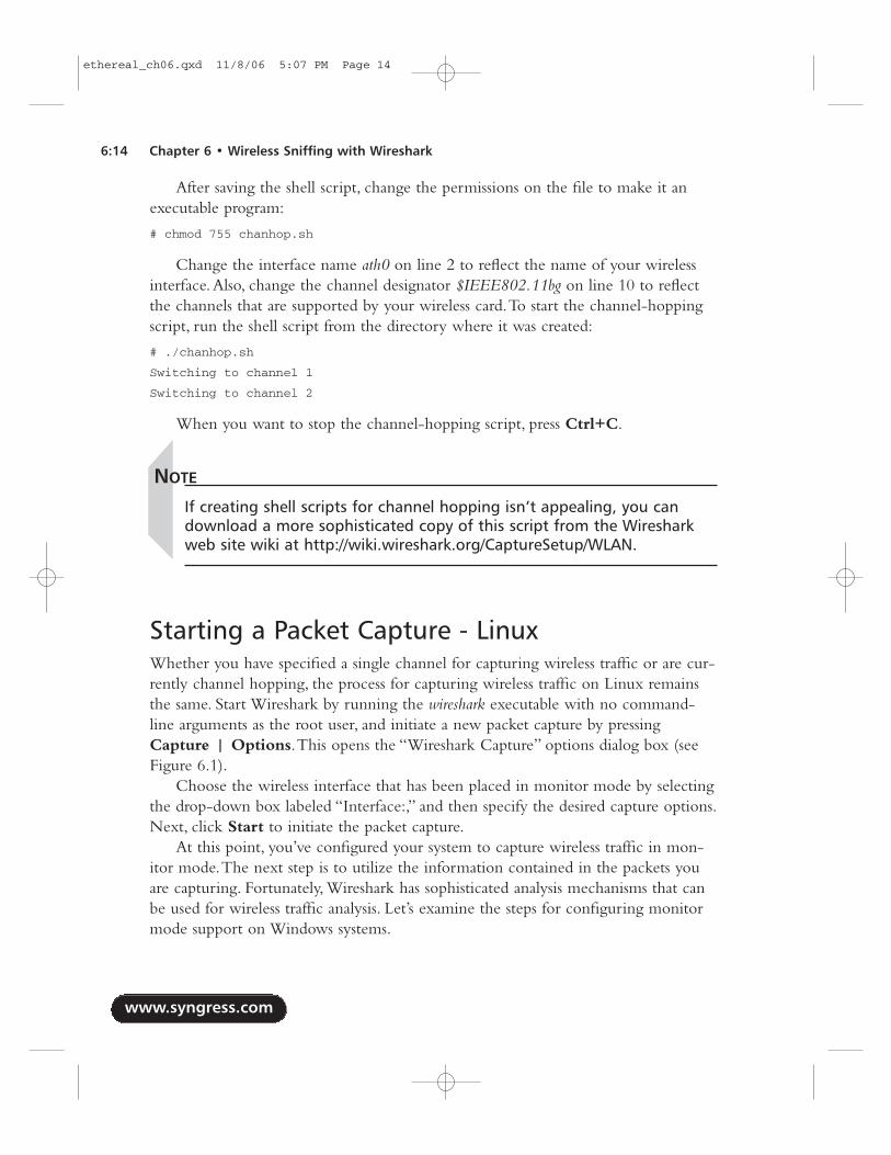
Starting a Packet Capture - LinuxWhether you have specified a single channel for capturing wireless traffic or are cur-rently channel hopping, the process for capturing wireless traffic on Linux remainsthe same. Start Wireshark by running the wireshark executable with no command-line arguments as the root user, and initiate a new packet capture by pressingCapture | Options.This opens the “Wireshark Capture” options dialog box (seeFigure 6.1).
Choose the wireless interface that has been placed in monitor mode by selectingthe drop-down box labeled “Interface:,” and then specify the desired capture options.Next, click Start to initiate the packet capture.
At this point, you’ve configured your system to capture wireless traffic in mon-itor mode.The next step is to utilize the information contained in the packets youare capturing. Fortunately, Wireshark has sophisticated analysis mechanisms that canbe used for wireless traffic analysis. Let’s examine the steps for configuring monitormode support on Windows systems.
www.syngress.com
6:14 Chapter 6 • Wireless Sniffing with Wireshark
ethereal_ch06.qxd 11/8/06 5:07 PM Page 14
Getting Support for Monitor Mode -WindowsUnfortunately, Windows drivers for wireless cards do not normally include supportfor monitor mode access, instead restricting users to operating the card in managedmode. Fortunately, through a combination of commercial and open-source software,we can overcome this limitation to use Windows hosts for wireless traffic analysiswith Wireshark.
Introducing AirPcapIn order to overcome the limitations with most wireless drivers for Windows sys-tems, the engineers at CACE Technologies have introduced a commercial productcalled AirPcap.A combination of a USB IEEE 802.11b/g adapter, supporting driversoftware, and a client configuration utility,AirPcap provides a simple mechanism tocapture wireless traffic in monitor mode on Windows workstations at a reasonablecost.AirPcap is available at www.cacetech.com.
After obtaining the AirPcap CD and Universal Serial Bus (USB) wirelessadapter, follow the installation instructions detailed in the AirPcap User’s Guide.Ensure you have installed the appropriate version (WinPcap 4.0 beta 1) of WinPcapto support the AirPcap.
www.syngress.com
Wireless Sniffing with Wireshark • Chapter 6 6:15
Figure 6.1 Wireshark Capture Options Dialog Box - Linux
ethereal_ch06.qxd 11/8/06 5:07 PM Page 15
NOTE
Unfortunately, at the time of this writing, there are no free softwaresolutions that allow Windows users to capture wireless traffic reliably,and without violating other software license restrictions. If you need toperform wireless traffic analysis with a Windows workstation, Wiresharkis an effective tool; however, you would have to purchase a driver andhardware combination that supports monitor mode.
If you want to avoid any costs associated with drivers for monitormode packet capture, you are encouraged to use a Linux option thatbundles monitor mode support with the free wireless drivers. Using abootable Linux CD such as Backtrack from www.remote-exploit.org, youcan create an easily accessible Linux environment by booting from theLinux CD and plugging in a supported wireless card.
TIP
Another option for Windows users is to use the licensed AiroPeek NXsoftware to collect packet captures. Since Wireshark can read AiroPeekNX’s .apc files, you can use Wireshark to augment the features you getfrom AiroPeek NX. Unfortunately, the demo version of AiroPeek NX doesnot allow you to save packet captures.
Specifying the Capture ChannelAfter installing the AirPcap drivers, start the AirPcap control panel tool by navigatingto Start | All Programs | airpcap | Airpcap Control Panel (see Figure 6.2).Using this utility, you can manipulate the following settings for the wireless capture,as described in Table 6.2.
www.syngress.com
6:16 Chapter 6 • Wireless Sniffing with Wireshark
ethereal_ch06.qxd 11/8/06 5:07 PM Page 16
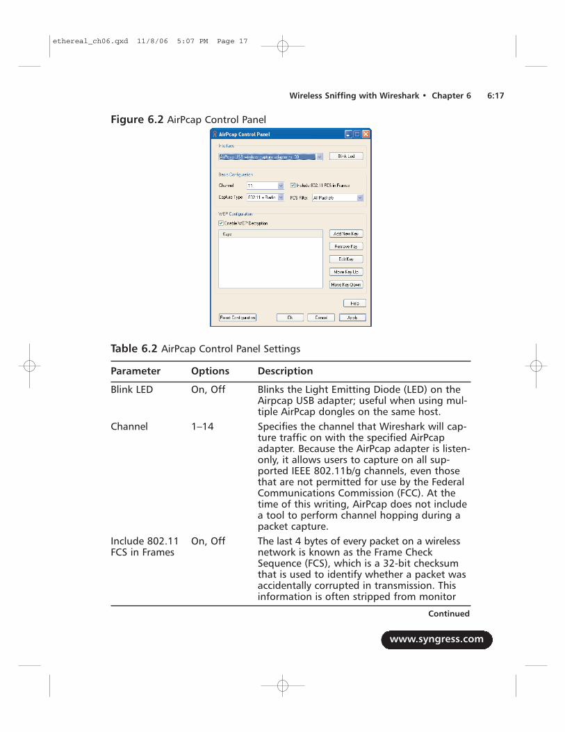
Table 6.2 AirPcap Control Panel Settings
Parameter Options Description
Blink LED On, Off Blinks the Light Emitting Diode (LED) on theAirpcap USB adapter; useful when using mul-tiple AirPcap dongles on the same host.
Channel 1–14 Specifies the channel that Wireshark will cap-ture traffic on with the specified AirPcapadapter. Because the AirPcap adapter is listen-only, it allows users to capture on all sup-ported IEEE 802.11b/g channels, even thosethat are not permitted for use by the FederalCommunications Commission (FCC). At thetime of this writing, AirPcap does not includea tool to perform channel hopping during apacket capture.
Include 802.11 On, Off The last 4 bytes of every packet on a wirelessFCS in Frames network is known as the Frame Check
Sequence (FCS), which is a 32-bit checksumthat is used to identify whether a packet wasaccidentally corrupted in transmission. Thisinformation is often stripped from monitor
www.syngress.com
Wireless Sniffing with Wireshark • Chapter 6 6:17
Figure 6.2 AirPcap Control Panel
Continued
ethereal_ch06.qxd 11/8/06 5:07 PM Page 17
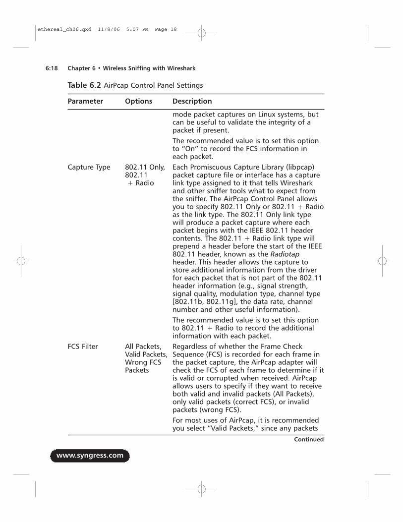
Table 6.2 AirPcap Control Panel Settings
Parameter Options Description
mode packet captures on Linux systems, butcan be useful to validate the integrity of apacket if present.The recommended value is to set this optionto “On” to record the FCS information ineach packet.
Capture Type 802.11 Only, Each Promiscuous Capture Library (libpcap) 802.11 packet capture file or interface has a capture + Radio link type assigned to it that tells Wireshark
and other sniffer tools what to expect fromthe sniffer. The AirPcap Control Panel allowsyou to specify 802.11 Only or 802.11 + Radioas the link type. The 802.11 Only link typewill produce a packet capture where eachpacket begins with the IEEE 802.11 headercontents. The 802.11 + Radio link type willprepend a header before the start of the IEEE802.11 header, known as the Radiotapheader. This header allows the capture tostore additional information from the driverfor each packet that is not part of the 802.11header information (e.g., signal strength,signal quality, modulation type, channel type[802.11b, 802.11g], the data rate, channelnumber and other useful information).The recommended value is to set this optionto 802.11 + Radio to record the additionalinformation with each packet.
FCS Filter All Packets, Regardless of whether the Frame Check Valid Packets, Sequence (FCS) is recorded for each frame in Wrong FCS the packet capture, the AirPcap adapter will Packets check the FCS of each frame to determine if it
is valid or corrupted when received. AirPcapallows users to specify if they want to receiveboth valid and invalid packets (All Packets),only valid packets (correct FCS), or invalidpackets (wrong FCS).For most uses of AirPcap, it is recommendedyou select “Valid Packets,” since any packets
www.syngress.com
6:18 Chapter 6 • Wireless Sniffing with Wireshark
Continued
ethereal_ch06.qxd 11/8/06 5:07 PM Page 18
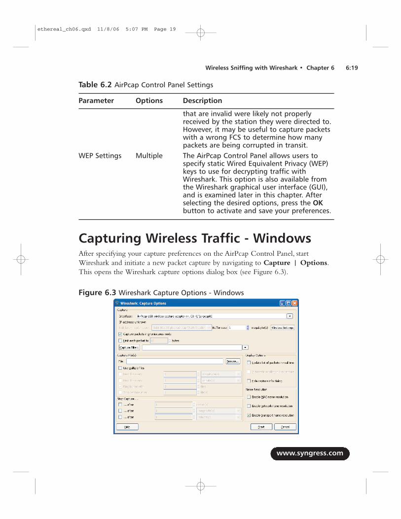
Table 6.2 AirPcap Control Panel Settings
Parameter Options Description
that are invalid were likely not properlyreceived by the station they were directed to.However, it may be useful to capture packetswith a wrong FCS to determine how manypackets are being corrupted in transit.
WEP Settings Multiple The AirPcap Control Panel allows users tospecify static Wired Equivalent Privacy (WEP)keys to use for decrypting traffic withWireshark. This option is also available fromthe Wireshark graphical user interface (GUI),and is examined later in this chapter. Afterselecting the desired options, press the OKbutton to activate and save your preferences.
Capturing Wireless Traffic - WindowsAfter specifying your capture preferences on the AirPcap Control Panel, startWireshark and initiate a new packet capture by navigating to Capture | Options.This opens the Wireshark capture options dialog box (see Figure 6.3).
www.syngress.com
Wireless Sniffing with Wireshark • Chapter 6 6:19
Figure 6.3 Wireshark Capture Options - Windows
ethereal_ch06.qxd 11/8/06 5:07 PM Page 19
Choose the AirPcap interface by selecting the drop-down box labeled“Interface:,” and then specify the desired capture options. Next, click Start to ini-tiate the packet capture. Stop the capture after you have collected the desiredamount of traffic by clicking on the Stop button, or go to Capture | Stop in thecapture dialog box.
At this point, you are capturing wireless traffic in monitor mode on Windows.Next comes the challenging part: extracting useful information from the packet cap-ture contents.The following section examines the many Wireshark features thatmake this analysis easier.
Analyzing Wireless TrafficRegardless of whether you are reading a packet capture from a stored file or from alive interface on a Windows or Linux host, Wireshark’s analysis features are nearlyidentical. Wireshark offers many useful features for analyzing wireless traffic,including detailed protocol dissectors, powerful display filters, customizable displayproperties, and the ability to decrypt wireless traffic. Each of these features are exam-ined in detail.
Navigating the Packet Details WindowOne of the most impressive Wireshark features is the ability to dissect the contentsof traffic and present it in a collapsible “tree-like” manner. For wireless traffic,Wireshark presents the Frame Dissector window starting with frame statistics, andthen the 802.11 MAC layer contents. If additional data follows for the 802.11header, Wireshark logically divides each of the protocols that follow into a newwindow.
Frame StatisticsThe first group in the Packet Details window detailed summary information aboutthe currently selected frame.The Frame window doesn’t display any of the selectedframe’s contents, but rather general information contained in the packet capture forthe selected frame (see Table 6.3).
www.syngress.com
6:20 Chapter 6 • Wireless Sniffing with Wireshark
ethereal_ch06.qxd 11/8/06 5:07 PM Page 20
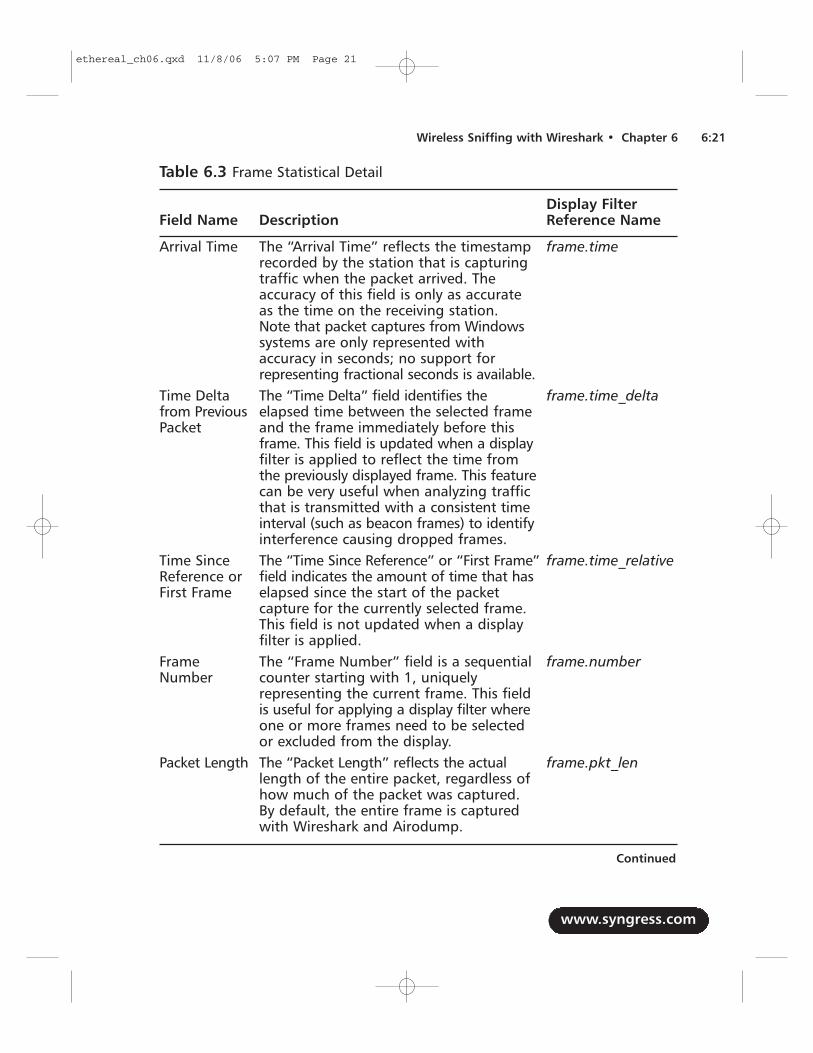
Table 6.3 Frame Statistical Detail
Display FilterField Name Description Reference Name
Arrival Time The “Arrival Time” reflects the timestamp frame.timerecorded by the station that is capturing traffic when the packet arrived. The accuracy of this field is only as accurate as the time on the receiving station. Note that packet captures from Windows systems are only represented with accuracy in seconds; no support for representing fractional seconds is available.
Time Delta The “Time Delta” field identifies the frame.time_deltafrom Previous elapsed time between the selected frame Packet and the frame immediately before this
frame. This field is updated when a displayfilter is applied to reflect the time from the previously displayed frame. This feature can be very useful when analyzing traffic that is transmitted with a consistent time interval (such as beacon frames) to identify interference causing dropped frames.
Time Since The “Time Since Reference” or “First Frame” frame.time_relativeReference or field indicates the amount of time that has First Frame elapsed since the start of the packet
capture for the currently selected frame. This field is not updated when a display filter is applied.
Frame The “Frame Number” field is a sequential frame.numberNumber counter starting with 1, uniquely
representing the current frame. This field is useful for applying a display filter where one or more frames need to be selected or excluded from the display.
Packet Length The “Packet Length” reflects the actual frame.pkt_lenlength of the entire packet, regardless of how much of the packet was captured. By default, the entire frame is captured with Wireshark and Airodump.
www.syngress.com
Wireless Sniffing with Wireshark • Chapter 6 6:21
Continued
ethereal_ch06.qxd 11/8/06 5:07 PM Page 21
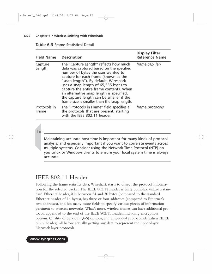
Table 6.3 Frame Statistical Detail
Display FilterField Name Description Reference Name
Capture The “Capture Length” reflects how much frame.cap_lenLength data was captured based on the specified
number of bytes the user wanted to capture for each frame (known as the “snap length”). By default, Wireshark uses a snap length of 65,535 bytes to capture the entire frame contents. When an alternative snap length is specified, the capture length can be smaller if the frame size is smaller than the snap length.
Protocols in The “Protocols in Frame” field specifies all frame.protocolsFrame the protocols that are present, starting
with the IEEE 802.11 header.
TIP
Maintaining accurate host time is important for many kinds of protocolanalysis, and especially important if you want to correlate events acrossmultiple systems. Consider using the Network Time Protocol (NTP) onyou Linux or Windows clients to ensure your local system time is alwaysaccurate.
IEEE 802.11 HeaderFollowing the frame statistics data, Wireshark starts to dissect the protocol informa-tion for the selected packet.The IEEE 802.11 header is fairly complex; unlike a stan-dard Ethernet header, it is between 24 and 30 bytes (compared to the standardEthernet header of 14 bytes), has three or four addresses (compared to Ethernet’stwo addresses), and has many more fields to specify various pieces of informationpertinent to wireless networks. What’s more, wireless frames can have additional pro-tocols appended to the end of the IEEE 802.11 header, including encryptionoptions, Quality of Service (QoS) options, and embedded protocol identifiers (IEEE802.2 header), all before actually getting any data to represent the upper-layerNetwork layer protocols.
www.syngress.com
6:22 Chapter 6 • Wireless Sniffing with Wireshark
ethereal_ch06.qxd 11/8/06 5:07 PM Page 22
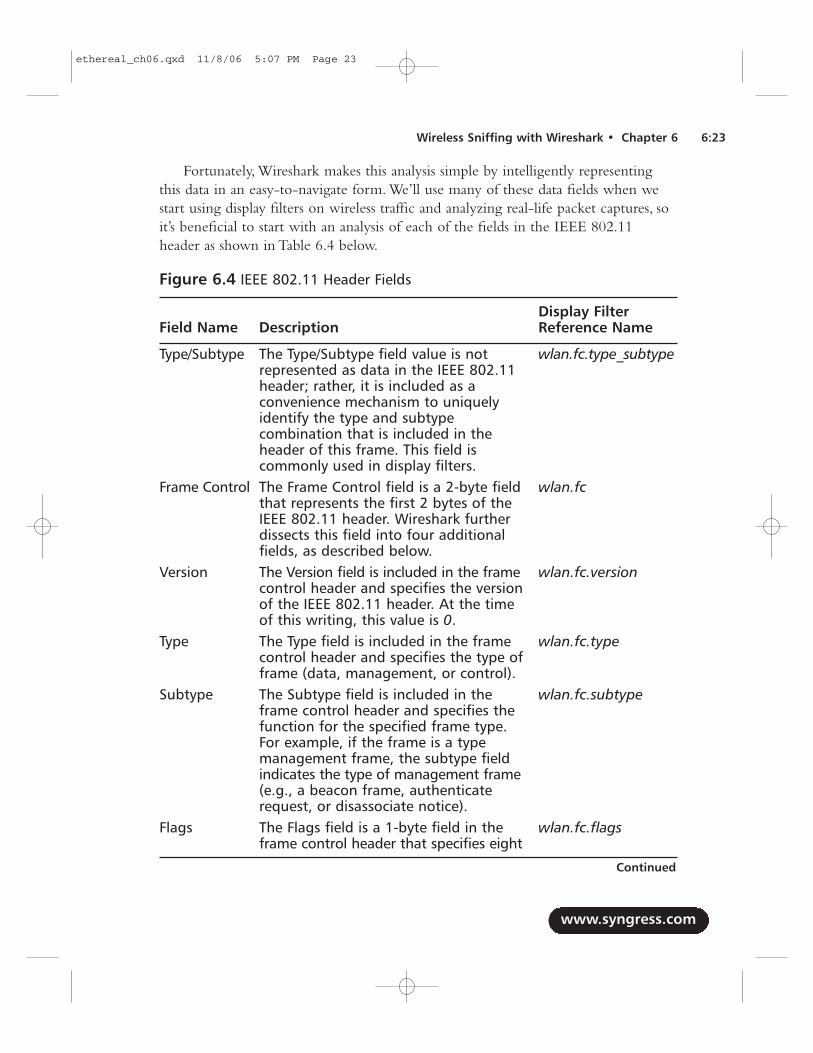
Fortunately, Wireshark makes this analysis simple by intelligently representingthis data in an easy-to-navigate form. We’ll use many of these data fields when westart using display filters on wireless traffic and analyzing real-life packet captures, soit’s beneficial to start with an analysis of each of the fields in the IEEE 802.11header as shown in Table 6.4 below.
Figure 6.4 IEEE 802.11 Header Fields
Display Filter Field Name Description Reference Name
Type/Subtype The Type/Subtype field value is not wlan.fc.type_subtyperepresented as data in the IEEE 802.11 header; rather, it is included as a convenience mechanism to uniquely identify the type and subtype combination that is included in the header of this frame. This field is commonly used in display filters.
Frame Control The Frame Control field is a 2-byte field wlan.fcthat represents the first 2 bytes of the IEEE 802.11 header. Wireshark further dissects this field into four additional fields, as described below.
Version The Version field is included in the frame wlan.fc.versioncontrol header and specifies the version of the IEEE 802.11 header. At the time of this writing, this value is 0.
Type The Type field is included in the frame wlan.fc.typecontrol header and specifies the type of frame (data, management, or control).
Subtype The Subtype field is included in the wlan.fc.subtypeframe control header and specifies the function for the specified frame type. For example, if the frame is a type management frame, the subtype field indicates the type of management frame (e.g., a beacon frame, authenticate request, or disassociate notice).
Flags The Flags field is a 1-byte field in the wlan.fc.flagsframe control header that specifies eight
www.syngress.com
Wireless Sniffing with Wireshark • Chapter 6 6:23
Continued
ethereal_ch06.qxd 11/8/06 5:07 PM Page 23
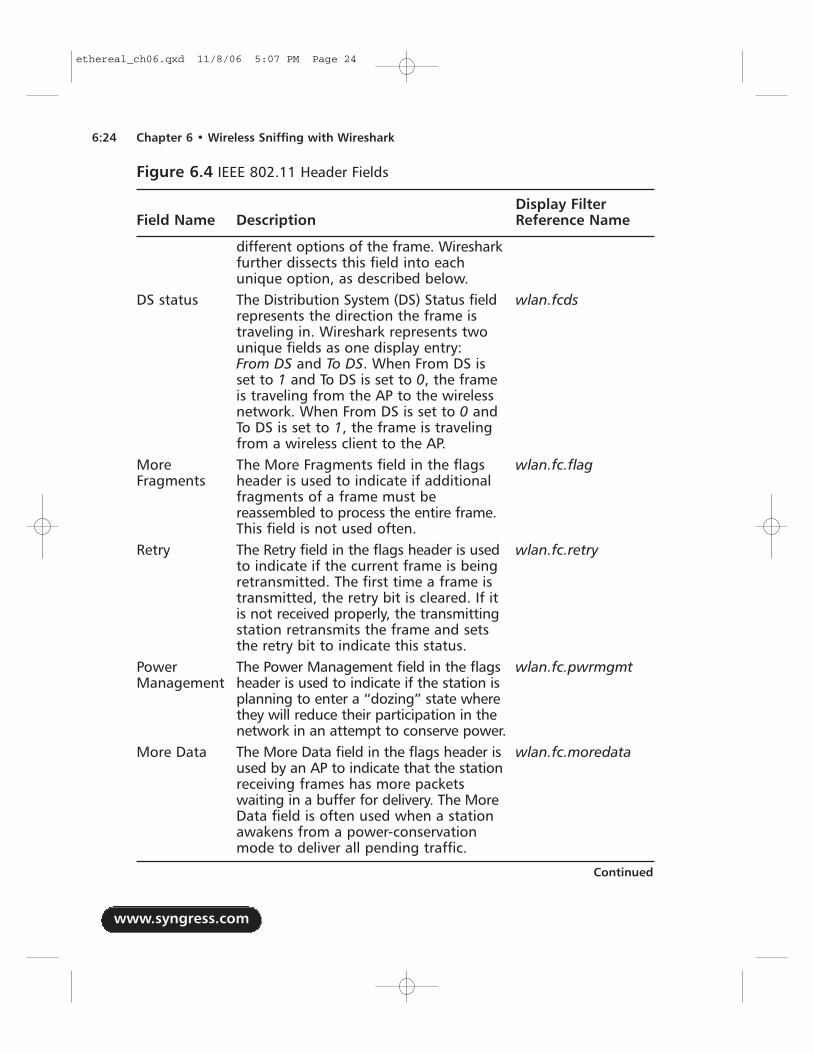
Figure 6.4 IEEE 802.11 Header Fields
Display Filter Field Name Description Reference Name
different options of the frame. Wireshark further dissects this field into each unique option, as described below.
DS status The Distribution System (DS) Status field wlan.fcdsrepresents the direction the frame is traveling in. Wireshark represents two unique fields as one display entry: From DS and To DS. When From DS is set to 1 and To DS is set to 0, the frame is traveling from the AP to the wireless network. When From DS is set to 0 and To DS is set to 1, the frame is traveling from a wireless client to the AP.
More The More Fragments field in the flags wlan.fc.flagFragments header is used to indicate if additional
fragments of a frame must be reassembled to process the entire frame. This field is not used often.
Retry The Retry field in the flags header is used wlan.fc.retryto indicate if the current frame is being retransmitted. The first time a frame is transmitted, the retry bit is cleared. If it is not received properly, the transmitting station retransmits the frame and sets the retry bit to indicate this status.
Power The Power Management field in the flags wlan.fc.pwrmgmtManagement header is used to indicate if the station is
planning to enter a “dozing” state where they will reduce their participation in the network in an attempt to conserve power.
More Data The More Data field in the flags header is wlan.fc.moredataused by an AP to indicate that the stationreceiving frames has more packets waiting in a buffer for delivery. The More Data field is often used when a station awakens from a power-conservation mode to deliver all pending traffic.
www.syngress.com
6:24 Chapter 6 • Wireless Sniffing with Wireshark
Continued
ethereal_ch06.qxd 11/8/06 5:07 PM Page 24
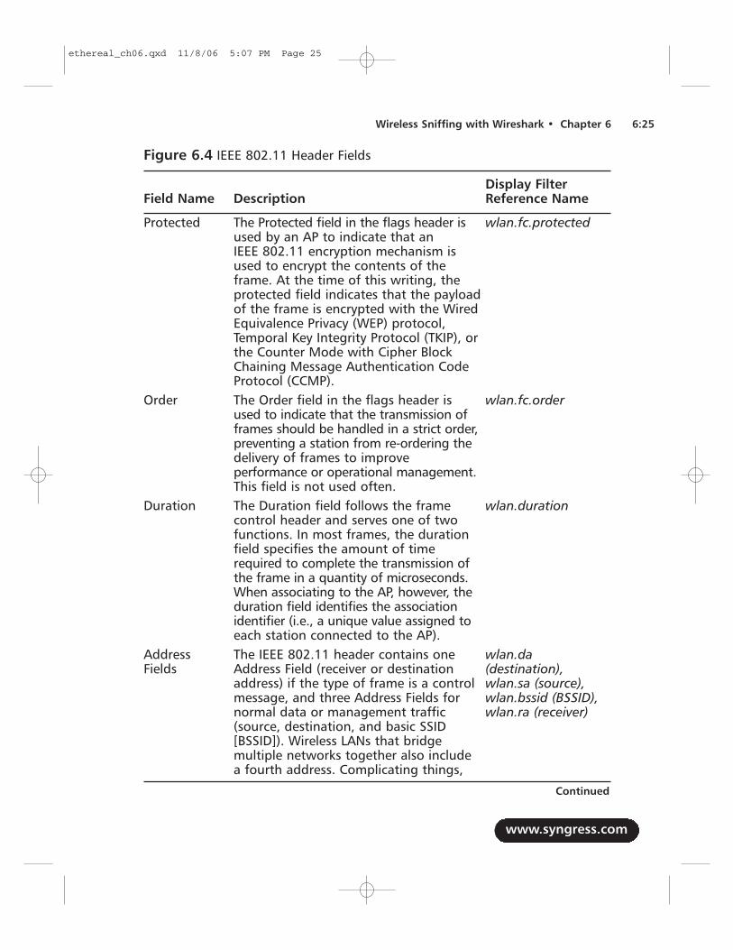
Figure 6.4 IEEE 802.11 Header Fields
Display Filter Field Name Description Reference Name
Protected The Protected field in the flags header is wlan.fc.protectedused by an AP to indicate that an IEEE 802.11 encryption mechanism is used to encrypt the contents of the frame. At the time of this writing, the protected field indicates that the payload of the frame is encrypted with the Wired Equivalence Privacy (WEP) protocol, Temporal Key Integrity Protocol (TKIP), or the Counter Mode with Cipher Block Chaining Message Authentication Code Protocol (CCMP).
Order The Order field in the flags header is wlan.fc.orderused to indicate that the transmission of frames should be handled in a strict order, preventing a station from re-ordering the delivery of frames to improve performance or operational management.This field is not used often.
Duration The Duration field follows the frame wlan.durationcontrol header and serves one of two functions. In most frames, the duration field specifies the amount of time required to complete the transmission of the frame in a quantity of microseconds. When associating to the AP, however, the duration field identifies the association identifier (i.e., a unique value assigned to each station connected to the AP).
Address The IEEE 802.11 header contains one wlan.da Fields Address Field (receiver or destination (destination),
address) if the type of frame is a control wlan.sa (source), message, and three Address Fields for wlan.bssid (BSSID), normal data or management traffic wlan.ra (receiver)(source, destination, and basic SSID [BSSID]). Wireless LANs that bridge multiple networks together also include a fourth address. Complicating things,
www.syngress.com
Wireless Sniffing with Wireshark • Chapter 6 6:25
Continued
ethereal_ch06.qxd 11/8/06 5:07 PM Page 25
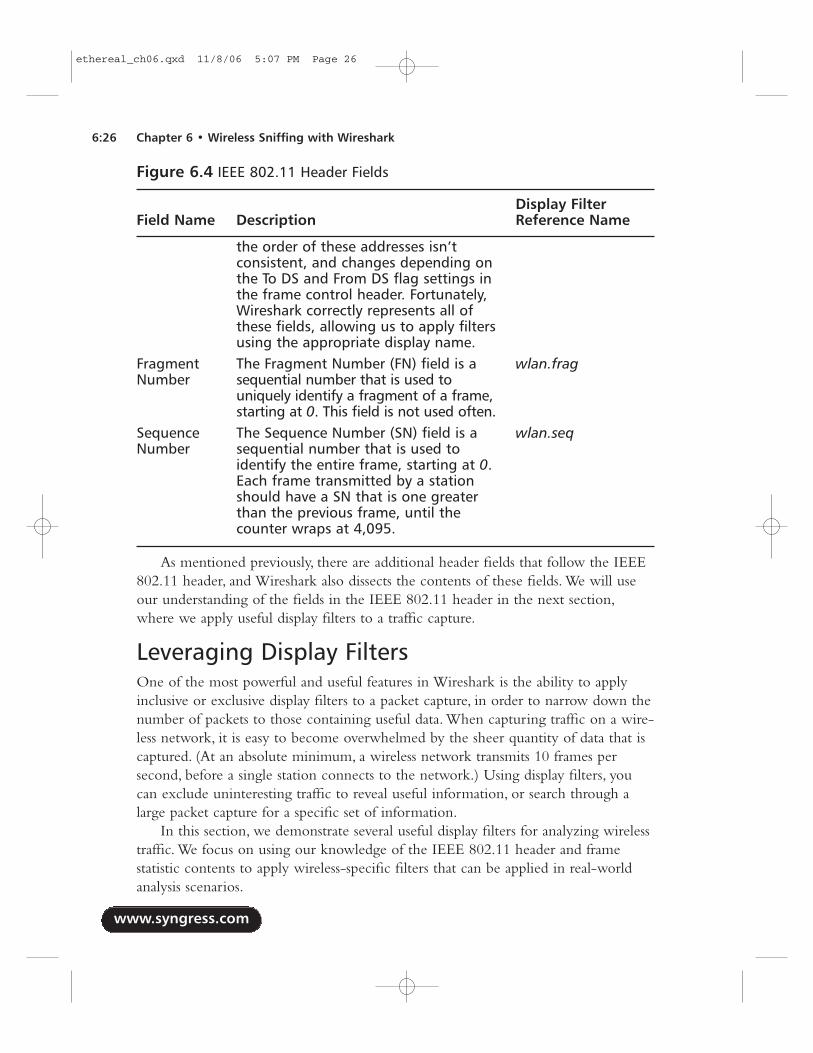
Figure 6.4 IEEE 802.11 Header Fields
Display Filter Field Name Description Reference Name
the order of these addresses isn’t consistent, and changes depending on the To DS and From DS flag settings in the frame control header. Fortunately, Wireshark correctly represents all of these fields, allowing us to apply filters using the appropriate display name.
Fragment The Fragment Number (FN) field is a wlan.fragNumber sequential number that is used to
uniquely identify a fragment of a frame, starting at 0. This field is not used often.
Sequence The Sequence Number (SN) field is a wlan.seqNumber sequential number that is used to
identify the entire frame, starting at 0. Each frame transmitted by a station should have a SN that is one greater than the previous frame, until the counter wraps at 4,095.
As mentioned previously, there are additional header fields that follow the IEEE802.11 header, and Wireshark also dissects the contents of these fields. We will useour understanding of the fields in the IEEE 802.11 header in the next section,where we apply useful display filters to a traffic capture.
Leveraging Display FiltersOne of the most powerful and useful features in Wireshark is the ability to applyinclusive or exclusive display filters to a packet capture, in order to narrow down thenumber of packets to those containing useful data. When capturing traffic on a wire-less network, it is easy to become overwhelmed by the sheer quantity of data that iscaptured. (At an absolute minimum, a wireless network transmits 10 frames persecond, before a single station connects to the network.) Using display filters, youcan exclude uninteresting traffic to reveal useful information, or search through alarge packet capture for a specific set of information.
In this section, we demonstrate several useful display filters for analyzing wirelesstraffic. We focus on using our knowledge of the IEEE 802.11 header and framestatistic contents to apply wireless-specific filters that can be applied in real-worldanalysis scenarios.
www.syngress.com
6:26 Chapter 6 • Wireless Sniffing with Wireshark
ethereal_ch06.qxd 11/8/06 5:07 PM Page 26
Traffic for a Specific Basic Service SetAn IEEE 802.11 wireless network with an AP providing connectivity to one ormore client systems is known as a Basic Service Set (BSS).This is the most commonwireless LAN implementation, and is used everywhere from corporate networks tohotspot environments and high-security government institutions.
Each wireless AP is uniquely identified by the Basic Service Set Identifier(BSSID). Recall that the BSSID is one of the addresses found in the IEEE 802.11header, and is present in every data or management frame transmitted by a wirelessstation or an AP to uniquely identify the wireless LAN.
When traffic is captured in monitor mode, the wireless card reports all validIEEE 802.11 frames for the specified channel, regardless of the BSSID or the net-work name being used.This can also include traffic from other nearby channels,because many wireless cards also have sufficient radio sensitivity to capture trafficfrom other nearby frequencies (e.g., it’s not uncommon for a wireless card onchannel 3 to capture traffic from channels 1, 2, 3, 4, and 5).
TIP
The BSSID address is often the same Medium Access Control (MAC)address as the wireless card on the AP, when there is a single networkname configured. When multiple network names or virtual APs are con-figured, the BSSID may be similar to the MAC address of the AP’s wire-less card with minor variations (often in the last byte of the address).
When doing troubleshooting analysis, however, you usually want to limit theanalysis to traffic to and from a specific AP that is servicing the problematic client.Using display filters, you can easily exclude traffic from nearby APs and focus theanalysis on a specific AP. In this display filter, the goal is to identify all of the trafficfor a single AP.
Identify the Station MAC AddressWe start by obtaining the MAC address of the station that we are trou-bleshooting, or any station that is connected to the target BSS. On a Windowssystem, we can extract this information by running the ipconfig /all utility from acommand shell (see Figure 6.4). On a Linux system, use ifconfig -a to determinethe MAC address (see Figure 6.5).
www.syngress.com
Wireless Sniffing with Wireshark • Chapter 6 6:27
ethereal_ch06.qxd 11/8/06 5:07 PM Page 27
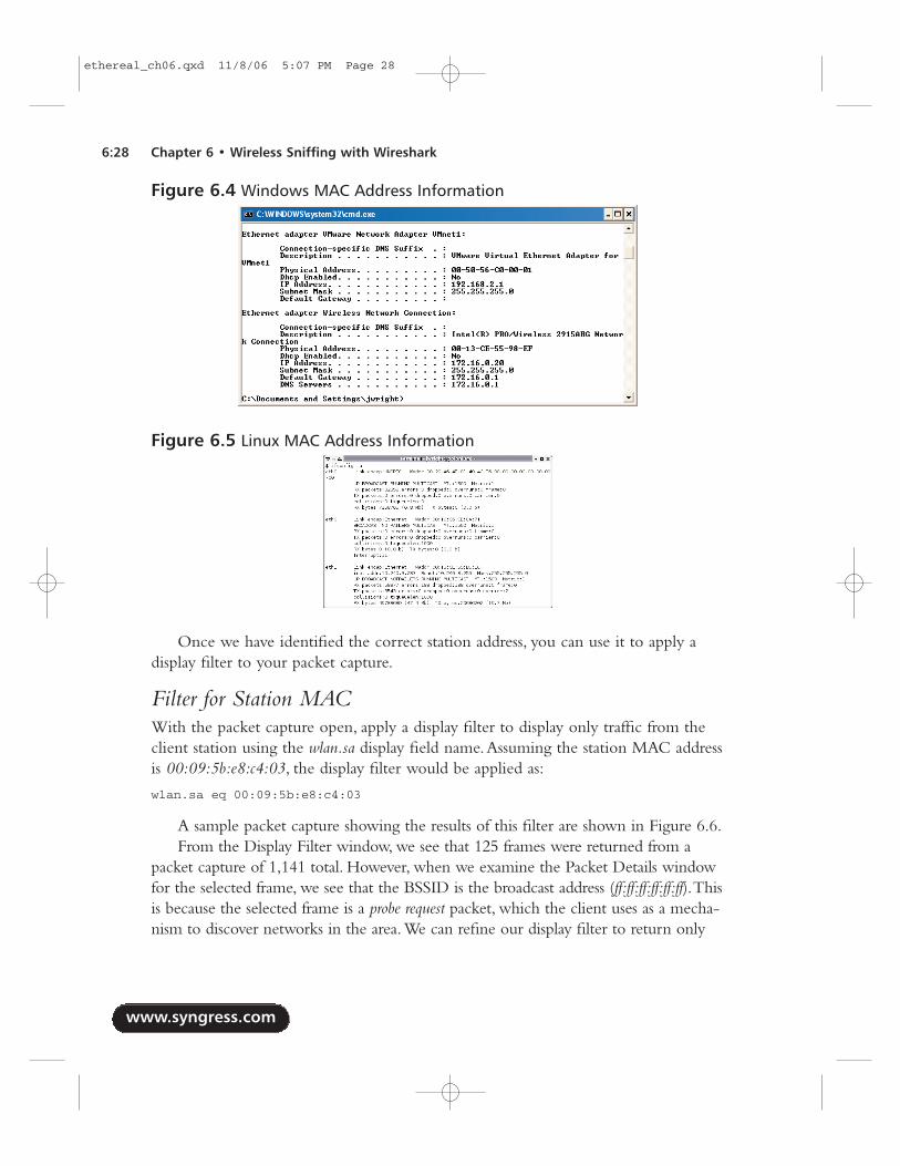
Once we have identified the correct station address, you can use it to apply adisplay filter to your packet capture.
Filter for Station MACWith the packet capture open, apply a display filter to display only traffic from theclient station using the wlan.sa display field name.Assuming the station MAC addressis 00:09:5b:e8:c4:03, the display filter would be applied as:
wlan.sa eq 00:09:5b:e8:c4:03
A sample packet capture showing the results of this filter are shown in Figure 6.6.From the Display Filter window, we see that 125 frames were returned from a
packet capture of 1,141 total. However, when we examine the Packet Details windowfor the selected frame, we see that the BSSID is the broadcast address (ff:ff:ff:ff:ff:ff).Thisis because the selected frame is a probe request packet, which the client uses as a mecha-nism to discover networks in the area.We can refine our display filter to return only
www.syngress.com
6:28 Chapter 6 • Wireless Sniffing with Wireshark
Figure 6.4 Windows MAC Address Information
Figure 6.5 Linux MAC Address Information
ethereal_ch06.qxd 11/8/06 5:07 PM Page 28
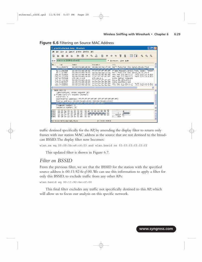
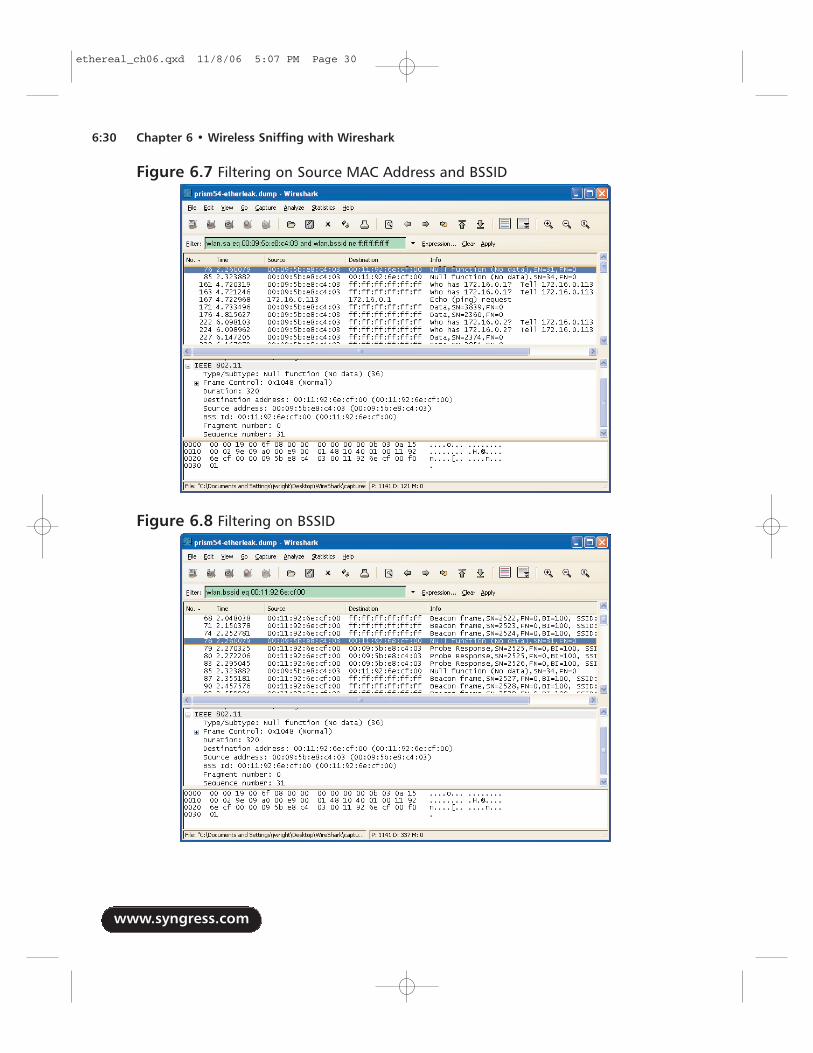
traffic destined specifically for the AP, by amending the display filter to return onlyframes with our station MAC address as the source that are not destined to the broad-cast BSSID.The display filter now becomes:
wlan.sa eq 00:09:5b:e8:c4:03 and wlan.bssid ne ff:ff:ff:ff:ff:ff
This updated filter is shown in Figure 6.7.
Filter on BSSIDFrom the previous filter, we see that the BSSID for the station with the specifiedsource address is 00:11:92:6e:cf:00. We can use this information to apply a filter foronly this BSSID, to exclude traffic from any other APs:
wlan.bssid eq 00:11:92:6e:cf:00
This final filter excludes any traffic not specifically destined to this AP, whichwill allow us to focus our analysis on this specific network.
www.syngress.com
Wireless Sniffing with Wireshark • Chapter 6 6:29
Figure 6.6 Filtering on Source MAC Address
ethereal_ch06.qxd 11/8/06 5:07 PM Page 29
www.syngress.com
6:30 Chapter 6 • Wireless Sniffing with Wireshark
Figure 6.7 Filtering on Source MAC Address and BSSID
Figure 6.8 Filtering on BSSID
ethereal_ch06.qxd 11/8/06 5:07 PM Page 30
Traffic for a Specific Extended Service SetFiltering for a specific BSS is useful if you can narrow your troubleshooting down toa specific AP; however, initially, you may need to take a broader look at your wirelessnetwork and assess traffic for all of the APs in your capture file. Indeed, many of theproblems in wireless networking have to do with roaming between APs, whichforces us to assess traffic from multiple APs. Fortunately, Wireshark display filterscome to the rescue.
When you configure and deploy a wireless network, each AP is configured withone or more network names (or SSIDs), also known as an Extended SSID (ESSID).When you deploy multiple APs that facilitate a client’s ability to roam between APs,all of the APs with the same SSID are referred to as participating in an ExtendedService Set (ESS).
In the display filter example, our goal is to identify all of the traffic for a specificESS identified by the SSID or network name. Unfortunately, we cannot apply a filterto identify all frames for a given SSID, as many management frames and all data andcontrol frames do not include the SSID information. Instead, we need to enumerateall the BSSIDs for a specified SSID to develop an inclusive filter.
Filter on SSIDThe first step is to apply a filter for a target SSID.As mentioned previously, this onlyreturns management frames that include the SSID information element; however, itwill present a list of all of the APs that use this SSID for additional filtering.
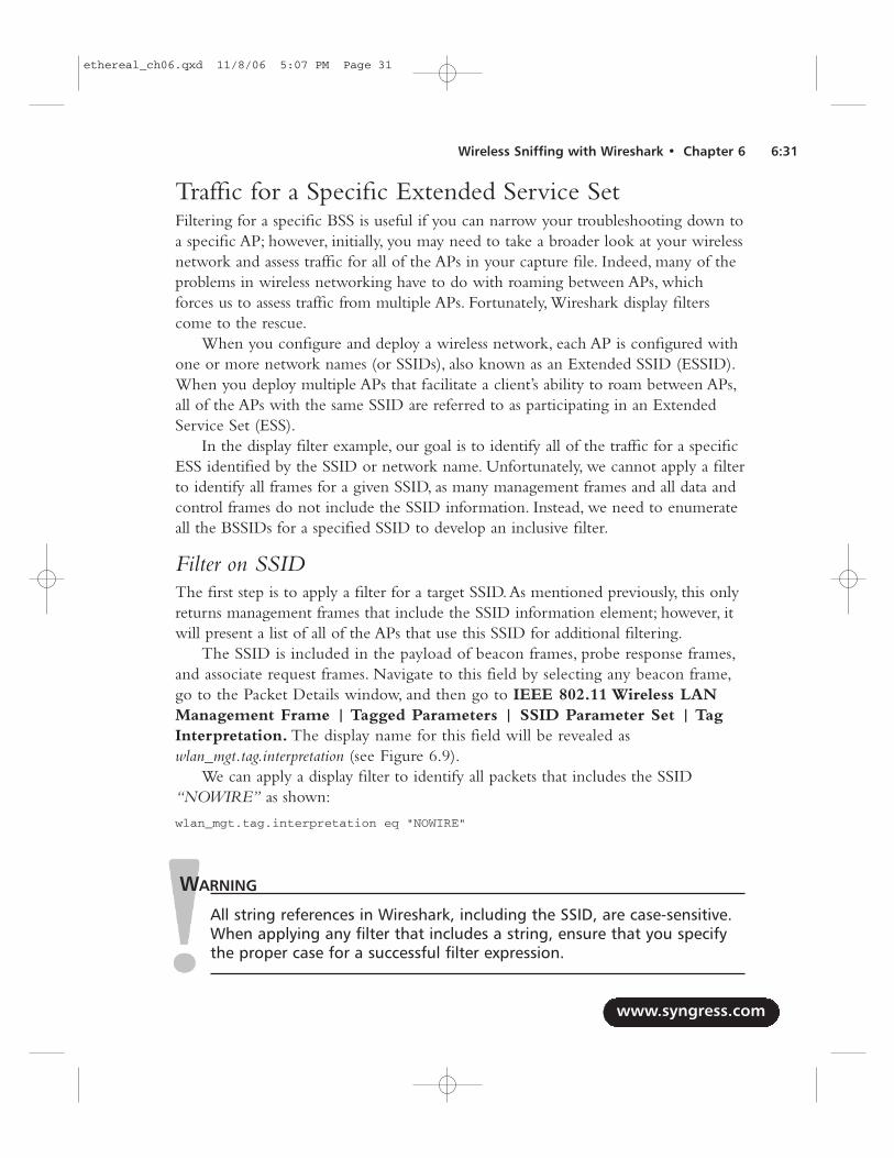
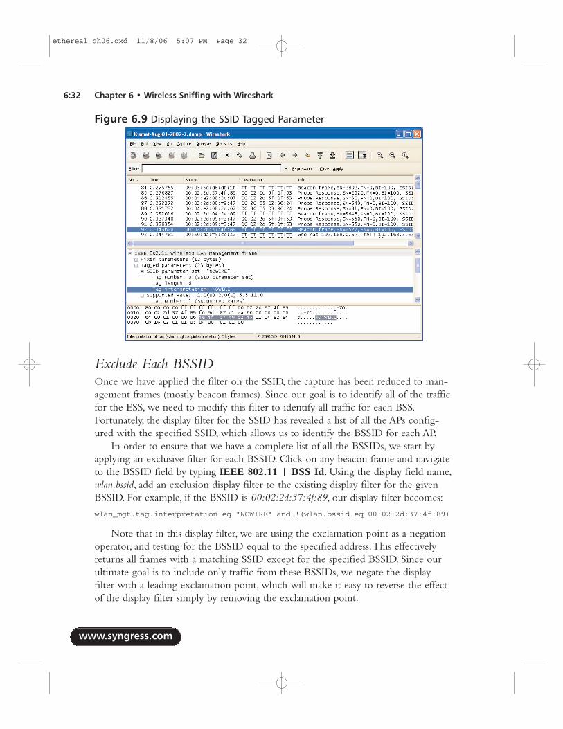
The SSID is included in the payload of beacon frames, probe response frames,and associate request frames. Navigate to this field by selecting any beacon frame,go to the Packet Details window, and then go to IEEE 802.11 Wireless LANManagement Frame | Tagged Parameters | SSID Parameter Set | TagInterpretation. The display name for this field will be revealed aswlan_mgt.tag.interpretation (see Figure 6.9).
We can apply a display filter to identify all packets that includes the SSID“NOWIRE” as shown:
wlan_mgt.tag.interpretation eq "NOWIRE"
WARNING
All string references in Wireshark, including the SSID, are case-sensitive.When applying any filter that includes a string, ensure that you specifythe proper case for a successful filter expression.
www.syngress.com
Wireless Sniffing with Wireshark • Chapter 6 6:31
ethereal_ch06.qxd 11/8/06 5:07 PM Page 31
Exclude Each BSSIDOnce we have applied the filter on the SSID, the capture has been reduced to man-agement frames (mostly beacon frames). Since our goal is to identify all of the trafficfor the ESS, we need to modify this filter to identify all traffic for each BSS.Fortunately, the display filter for the SSID has revealed a list of all the APs config-ured with the specified SSID, which allows us to identify the BSSID for each AP.
In order to ensure that we have a complete list of all the BSSIDs, we start byapplying an exclusive filter for each BSSID. Click on any beacon frame and navigateto the BSSID field by typing IEEE 802.11 | BSS Id. Using the display field name,wlan.bssid, add an exclusion display filter to the existing display filter for the givenBSSID. For example, if the BSSID is 00:02:2d:37:4f:89, our display filter becomes:
wlan_mgt.tag.interpretation eq "NOWIRE" and !(wlan.bssid eq 00:02:2d:37:4f:89)
Note that in this display filter, we are using the exclamation point as a negationoperator, and testing for the BSSID equal to the specified address.This effectivelyreturns all frames with a matching SSID except for the specified BSSID. Since ourultimate goal is to include only traffic from these BSSIDs, we negate the displayfilter with a leading exclamation point, which will make it easy to reverse the effectof the display filter simply by removing the exclamation point.
www.syngress.com
6:32 Chapter 6 • Wireless Sniffing with Wireshark
Figure 6.9 Displaying the SSID Tagged Parameter
ethereal_ch06.qxd 11/8/06 5:07 PM Page 32
Next, we repeat this step for each of the remaining frames in the packet capture,selecting another BSSID and adding it to the exclusion list. For example, if the nextBSSID is 00:40:05:df:93:c6, it is added to our exclusion list:
wlan_mgt.tag.interpretation eq "NOWIRE" and !(wlan.bssid eq00:02:2d:37:4f:89 or wlan.bssid eq 00:40:05:df:93:c6)
Repeat this process until there are no packets remaining in the capture display.
Invert FilterAt this point, our display filter should have no packets displayed. We have effectivelyidentified each AP in the packet capture that is associated with the specified SSID.Now, we can modify the packet capture to invert the exclusion filter on thewlan.bssid field to include all of the specified addresses. For example, if our packetcapture looks like this:
wlan_mgt.tag.interpretation eq "NOWIRE" and !(wlan.bssid eq00:02:2d:37:4f:89 or wlan.bssid eq 00:40:05:df:93:c6 or wlan.bssid eq00:40:96:36:80:f0)
We can modify it by removing the filter on the wlan_mgt.tag.interpretation field,and the exclamation point before the list of BSSIDs:
(wlan.bssid eq 00:02:2d:37:4f:89 or wlan.bssid eq 00:40:05:df:93:c6 orwlan.bssid eq 00:40:96:36:80:f0)
Applying this filter will return all traffic for the specified BSSIDs, effectivelyexcluding any traffic from neighboring networks that are not part of the initiallyspecified SSID.This allows us to focus our analysis only on traffic to and from thenetworks associated with the initial SSID.
TIP
After applying a significant display filter (as shown in this example), it iswise to save the resulting packets in a new packet capture file. This way,you can assess the results of your filter at a later time without having torepeat the filtering process. To save an extract of packets, click File |Save As, and then click on the Displayed button. Enter an appropriatefilename for the results of the display filter and click on Save.
You can also save the display filter itself by clicking Analyze | DisplayFilters. Enter a name for the display filter in the “Filter name” text boxand click on Save. When you want to recall the filter, go to Analyze |Display Filters and double-click on the desired display filter name.
www.syngress.com
Wireless Sniffing with Wireshark • Chapter 6 6:33
ethereal_ch06.qxd 11/8/06 5:07 PM Page 33
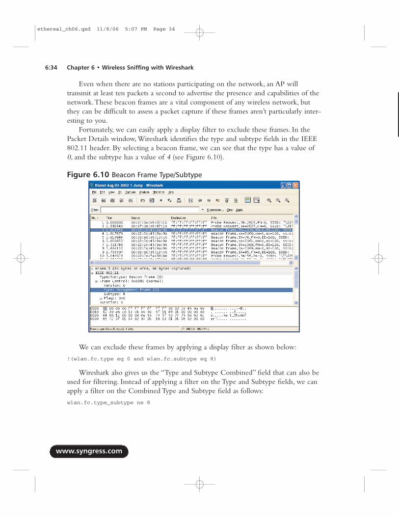
Even when there are no stations participating on the network, an AP willtransmit at least ten packets a second to advertise the presence and capabilities of thenetwork.These beacon frames are a vital component of any wireless network, butthey can be difficult to assess a packet capture if these frames aren’t particularly inter-esting to you.
Fortunately, we can easily apply a display filter to exclude these frames. In thePacket Details window, Wireshark identifies the type and subtype fields in the IEEE802.11 header. By selecting a beacon frame, we can see that the type has a value of0, and the subtype has a value of 4 (see Figure 6.10).
We can exclude these frames by applying a display filter as shown below:
!(wlan.fc.type eq 0 and wlan.fc.subtype eq 8)
Wireshark also gives us the “Type and Subtype Combined” field that can also beused for filtering. Instead of applying a filter on the Type and Subtype fields, we canapply a filter on the Combined Type and Subtype field as follows:
wlan.fc.type_subtype ne 8
www.syngress.com
6:34 Chapter 6 • Wireless Sniffing with Wireshark
Figure 6.10 Beacon Frame Type/Subtype
ethereal_ch06.qxd 11/8/06 5:07 PM Page 34
www.syngress.com
Wireless Sniffing with Wireshark • Chapter 6 6:35
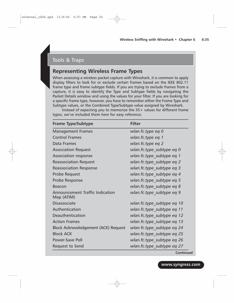
Representing Wireless Frame TypesWhen assessing a wireless packet capture with Wireshark, it is common to applydisplay filters to look for or exclude certain frames based on the IEEE 802.11frame type and frame subtype fields. If you are trying to exclude frames from acapture, it is easy to identify the Type and Subtype fields by navigating thePacket Details window and using the values for your filter. If you are looking fora specific frame type, however, you have to remember either the Frame Type andSubtype values, or the Combined Type/Subtype value assigned by Wireshark.
Instead of expecting you to memorize the 35+ values for different frametypes, we’ve included them here for easy reference.
Frame Type/Subtype Filter
Management Frames wlan.fc.type eq 0Control Frames wlan.fc.type eq 1Data Frames wlan.fc.type eq 2Association Request wlan.fc.type_subtype eq 0Association response wlan.fc.type_subtype eq 1Reassociation Request wlan.fc.type_subtype eq 2Reassociation Response wlan.fc.type_subtype eq 3Probe Request wlan.fc.type_subtype eq 4Probe Response wlan.fc.type_subtype eq 5Beacon wlan.fc.type_subtype eq 8Announcement Traffic Indication wlan.fc.type_subtype eq 9Map (ATIM) Disassociate wlan.fc.type_subtype eq 10Authentication wlan.fc.type_subtype eq 11Deauthentication wlan.fc.type_subtype eq 12Action Frames wlan.fc.type_subtype eq 13Block Acknowledgement (ACK) Request wlan.fc.type_subtype eq 24Block ACK wlan.fc.type_subtype eq 25Power-Save Poll wlan.fc.type_subtype eq 26Request to Send wlan.fc.type_subtype eq 27
Tools & Traps
Continued
ethereal_ch06.qxd 11/8/06 5:07 PM Page 35
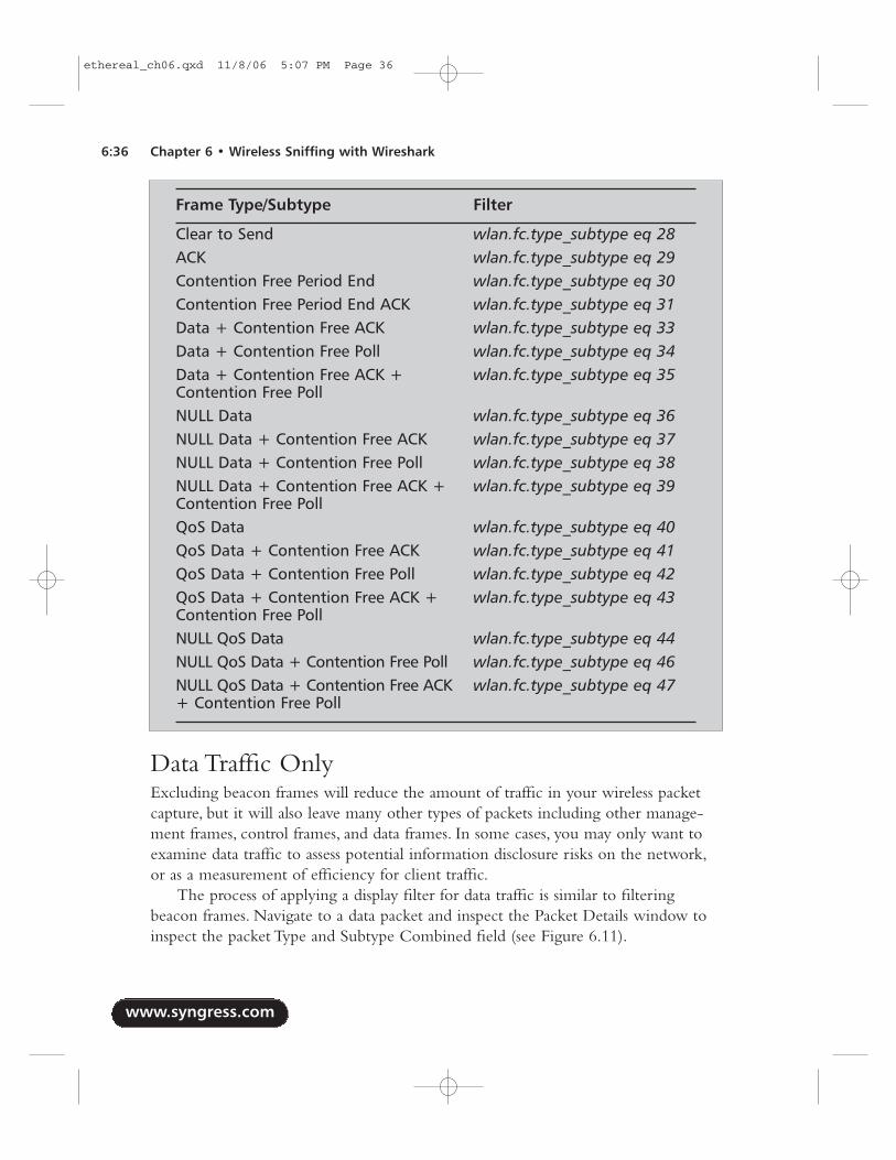
Data Traffic OnlyExcluding beacon frames will reduce the amount of traffic in your wireless packetcapture, but it will also leave many other types of packets including other manage-ment frames, control frames, and data frames. In some cases, you may only want toexamine data traffic to assess potential information disclosure risks on the network,or as a measurement of efficiency for client traffic.
The process of applying a display filter for data traffic is similar to filteringbeacon frames. Navigate to a data packet and inspect the Packet Details window toinspect the packet Type and Subtype Combined field (see Figure 6.11).
www.syngress.com
6:36 Chapter 6 • Wireless Sniffing with Wireshark
Frame Type/Subtype Filter
Clear to Send wlan.fc.type_subtype eq 28ACK wlan.fc.type_subtype eq 29Contention Free Period End wlan.fc.type_subtype eq 30Contention Free Period End ACK wlan.fc.type_subtype eq 31Data + Contention Free ACK wlan.fc.type_subtype eq 33Data + Contention Free Poll wlan.fc.type_subtype eq 34Data + Contention Free ACK + wlan.fc.type_subtype eq 35Contention Free PollNULL Data wlan.fc.type_subtype eq 36NULL Data + Contention Free ACK wlan.fc.type_subtype eq 37NULL Data + Contention Free Poll wlan.fc.type_subtype eq 38NULL Data + Contention Free ACK + wlan.fc.type_subtype eq 39Contention Free PollQoS Data wlan.fc.type_subtype eq 40QoS Data + Contention Free ACK wlan.fc.type_subtype eq 41QoS Data + Contention Free Poll wlan.fc.type_subtype eq 42QoS Data + Contention Free ACK + wlan.fc.type_subtype eq 43Contention Free PollNULL QoS Data wlan.fc.type_subtype eq 44NULL QoS Data + Contention Free Poll wlan.fc.type_subtype eq 46NULL QoS Data + Contention Free ACK wlan.fc.type_subtype eq 47+ Contention Free Poll
ethereal_ch06.qxd 11/8/06 5:07 PM Page 36
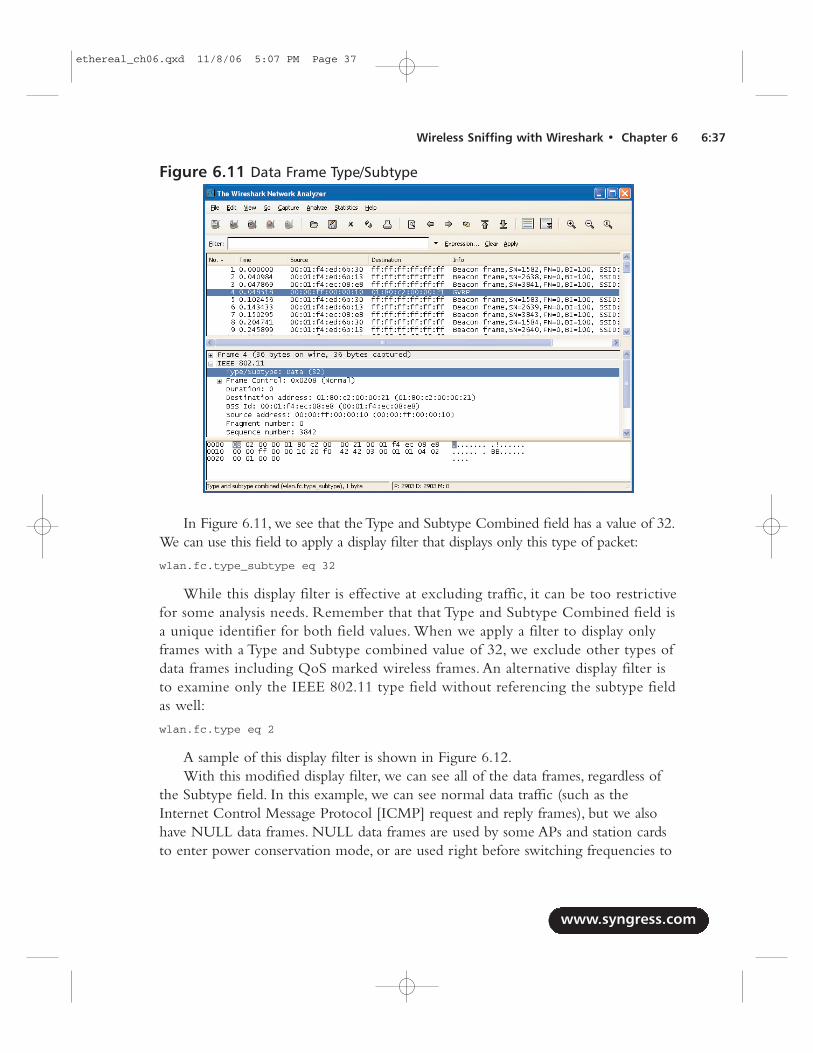
In Figure 6.11, we see that the Type and Subtype Combined field has a value of 32.We can use this field to apply a display filter that displays only this type of packet:
wlan.fc.type_subtype eq 32
While this display filter is effective at excluding traffic, it can be too restrictivefor some analysis needs. Remember that that Type and Subtype Combined field isa unique identifier for both field values. When we apply a filter to display onlyframes with a Type and Subtype combined value of 32, we exclude other types ofdata frames including QoS marked wireless frames. An alternative display filter isto examine only the IEEE 802.11 type field without referencing the subtype fieldas well:
wlan.fc.type eq 2
A sample of this display filter is shown in Figure 6.12.With this modified display filter, we can see all of the data frames, regardless of
the Subtype field. In this example, we can see normal data traffic (such as theInternet Control Message Protocol [ICMP] request and reply frames), but we alsohave NULL data frames. NULL data frames are used by some APs and station cardsto enter power conservation mode, or are used right before switching frequencies to
www.syngress.com
Wireless Sniffing with Wireshark • Chapter 6 6:37
Figure 6.11 Data Frame Type/Subtype
ethereal_ch06.qxd 11/8/06 5:07 PM Page 37
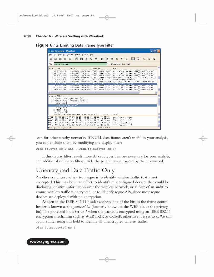
scan for other nearby networks. If NULL data frames aren’t useful in your analysis,you can exclude them by modifying the display filter:
wlan.fc.type eq 2 and !(wlan.fc.subtype eq 4)
If this display filter reveals more data subtypes than are necessary for your analysis,add additional exclusion filters inside the parenthesis, separated by the or keyword.
Unencrypted Data Traffic OnlyAnother common analysis technique is to identify wireless traffic that is notencrypted.This may be in an effort to identify misconfigured devices that could bedisclosing sensitive information over the wireless network, or as part of an audit toensure wireless traffic is encrypted, or to identify rogue APs, since most roguedevices are deployed with no encryption.
As seen in the IEEE 802.11 header analysis, one of the bits in the frame controlheader is known as the protected bit (formerly known as the WEP bit, or the privacybit).The protected bit is set to 1 when the packet is encrypted using an IEEE 802.11encryption mechanism such as WEP,TKIP, or CCMP; otherwise it is set to 0. We canapply a filter using this field to identify all unencrypted wireless traffic:
wlan.fc.protected ne 1
www.syngress.com
6:38 Chapter 6 • Wireless Sniffing with Wireshark
Figure 6.12 Limiting Data Frame Type Filter
ethereal_ch06.qxd 11/8/06 5:07 PM Page 38
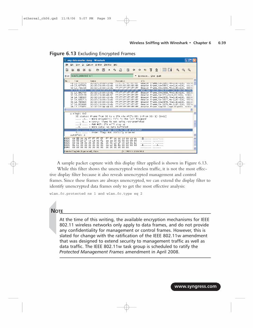
A sample packet capture with this display filter applied is shown in Figure 6.13.While this filter shows the unencrypted wireless traffic, it is not the most effec-
tive display filter because it also reveals unencrypted management and controlframes. Since these frames are always unencrypted, we can extend the display filter toidentify unencrypted data frames only to get the most effective analysis:
wlan.fc.protected ne 1 and wlan.fc.type eq 2
NOTE
At the time of this writing, the available encryption mechanisms for IEEE802.11 wireless networks only apply to data frames, and do not provideany confidentiality for management or control frames. However, this isslated for change with the ratification of the IEEE 802.11w amendmentthat was designed to extend security to management traffic as well asdata traffic. The IEEE 802.11w task group is scheduled to ratify theProtected Management Frames amendment in April 2008.
www.syngress.com
Wireless Sniffing with Wireshark • Chapter 6 6:39
Figure 6.13 Excluding Encrypted Frames
ethereal_ch06.qxd 11/8/06 5:07 PM Page 39
Identifying Hidden SSIDsMany organizations have adopted SSID cloaking, or prevented their APs from adver-tising their SSIDs to anyone who asks.While this provides a minimal measure of secu-rity, it is an ineffective mechanism for controlling access to the network and shouldonly be used in conjunction with a strong encryption and authentication mechanism.
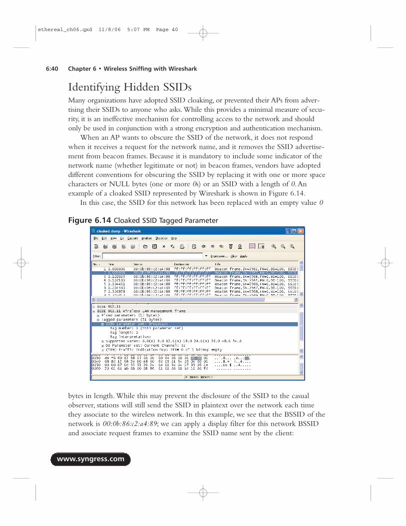
When an AP wants to obscure the SSID of the network, it does not respondwhen it receives a request for the network name, and it removes the SSID advertise-ment from beacon frames. Because it is mandatory to include some indicator of thenetwork name (whether legitimate or not) in beacon frames, vendors have adopteddifferent conventions for obscuring the SSID by replacing it with one or more spacecharacters or NULL bytes (one or more 0s) or an SSID with a length of 0.Anexample of a cloaked SSID represented by Wireshark is shown in Figure 6.14.
In this case, the SSID for this network has been replaced with an empty value 0
bytes in length. While this may prevent the disclosure of the SSID to the casualobserver, stations will still send the SSID in plaintext over the network each timethey associate to the wireless network. In this example, we see that the BSSID of thenetwork is 00:0b:86:c2:a4:89; we can apply a display filter for this network BSSIDand associate request frames to examine the SSID name sent by the client:
www.syngress.com
6:40 Chapter 6 • Wireless Sniffing with Wireshark
Figure 6.14 Cloaked SSID Tagged Parameter
ethereal_ch06.qxd 11/8/06 5:07 PM Page 40
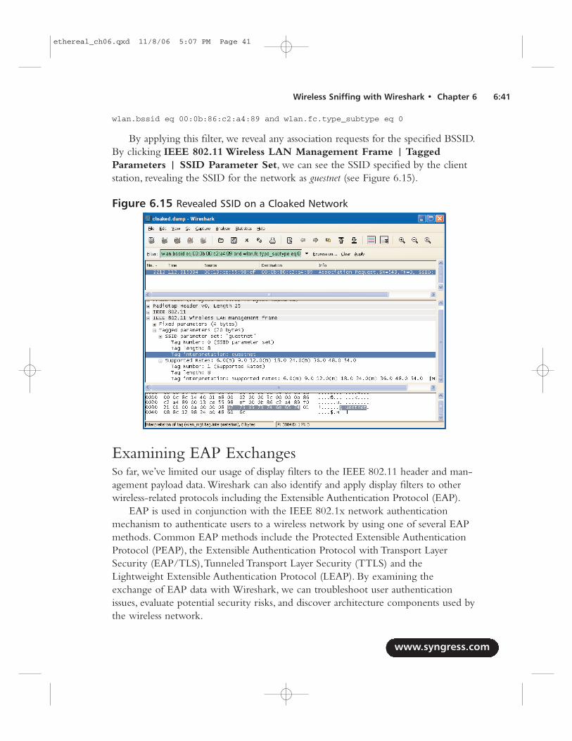
wlan.bssid eq 00:0b:86:c2:a4:89 and wlan.fc.type_subtype eq 0
By applying this filter, we reveal any association requests for the specified BSSID.By clicking IEEE 802.11 Wireless LAN Management Frame | TaggedParameters | SSID Parameter Set, we can see the SSID specified by the clientstation, revealing the SSID for the network as guestnet (see Figure 6.15).
Examining EAP ExchangesSo far, we’ve limited our usage of display filters to the IEEE 802.11 header and man-agement payload data. Wireshark can also identify and apply display filters to otherwireless-related protocols including the Extensible Authentication Protocol (EAP).
EAP is used in conjunction with the IEEE 802.1x network authenticationmechanism to authenticate users to a wireless network by using one of several EAPmethods. Common EAP methods include the Protected Extensible AuthenticationProtocol (PEAP), the Extensible Authentication Protocol with Transport LayerSecurity (EAP/TLS),Tunneled Transport Layer Security (TTLS) and theLightweight Extensible Authentication Protocol (LEAP). By examining theexchange of EAP data with Wireshark, we can troubleshoot user authenticationissues, evaluate potential security risks, and discover architecture components used bythe wireless network.
www.syngress.com
Wireless Sniffing with Wireshark • Chapter 6 6:41
Figure 6.15 Revealed SSID on a Cloaked Network
ethereal_ch06.qxd 11/8/06 5:07 PM Page 41
To identify any EAP traffic in a capture file, apply a display filter for the EAPOver LAN protocol:eapol
This filter will return any EAP traffic present in the capture file, includingauthentication requests, identity negotiation, key and encryption negotiationexchanges, and success or failure messages. Next, we examine each data exchangemechanism in the EAP exchange.
Identifying the EAP typeIf you are auditing a wireless network or trying to identify potentially misconfiguredclient systems, you may need to identify the EAP method used by those client sys-tems.The EAP method is reported in an EAP exchange in the EAP type field. Wecan use a display filter to identify frames that report this information:eap.type
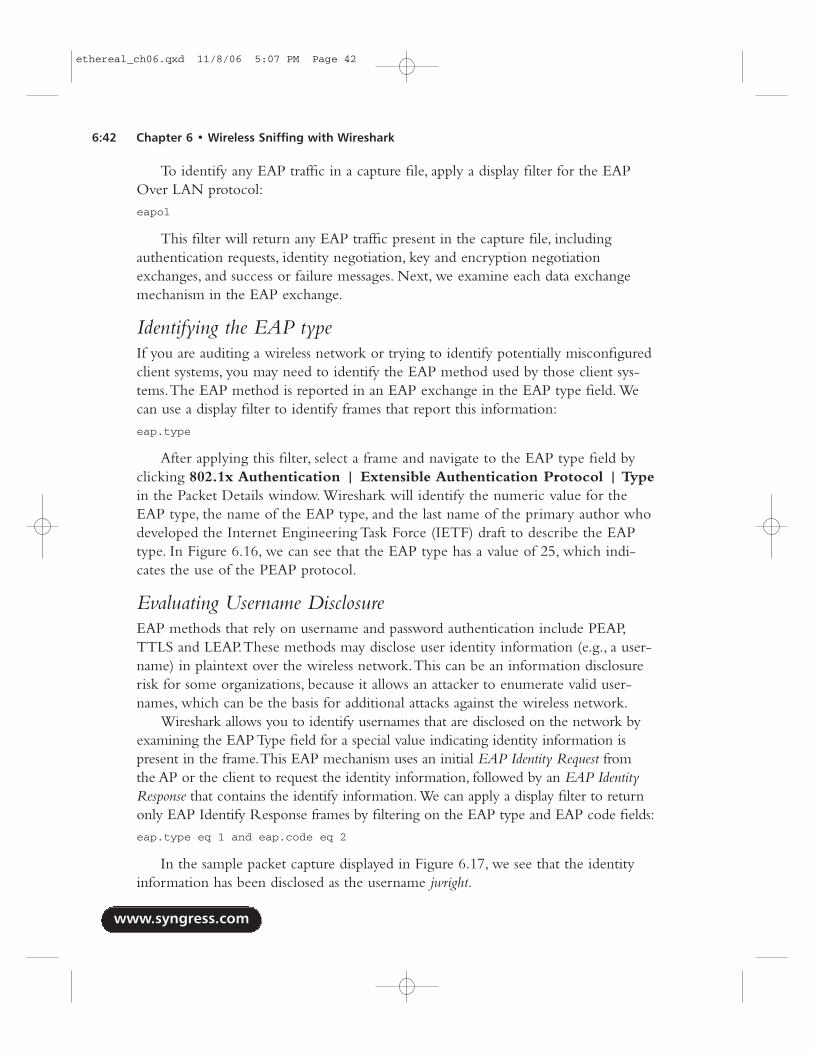
After applying this filter, select a frame and navigate to the EAP type field byclicking 802.1x Authentication | Extensible Authentication Protocol | Typein the Packet Details window. Wireshark will identify the numeric value for theEAP type, the name of the EAP type, and the last name of the primary author whodeveloped the Internet Engineering Task Force (IETF) draft to describe the EAPtype. In Figure 6.16, we can see that the EAP type has a value of 25, which indi-cates the use of the PEAP protocol.
Evaluating Username DisclosureEAP methods that rely on username and password authentication include PEAP,TTLS and LEAP.These methods may disclose user identity information (e.g., a user-name) in plaintext over the wireless network.This can be an information disclosurerisk for some organizations, because it allows an attacker to enumerate valid user-names, which can be the basis for additional attacks against the wireless network.
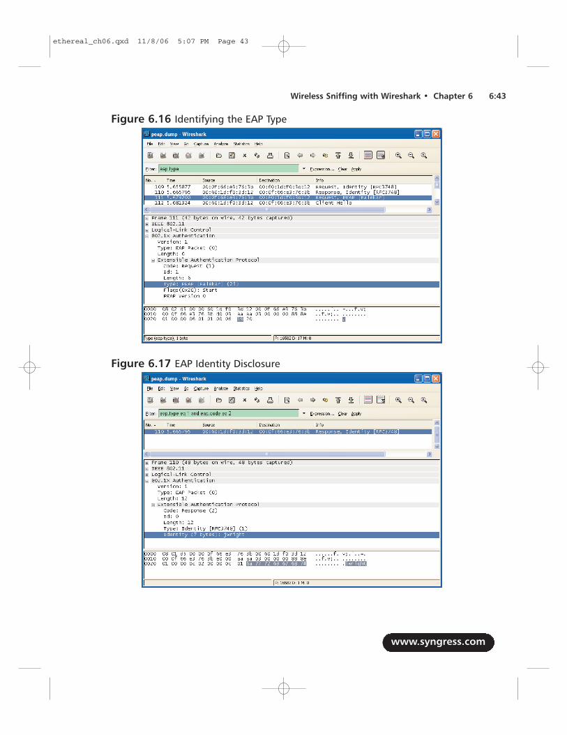
Wireshark allows you to identify usernames that are disclosed on the network byexamining the EAP Type field for a special value indicating identity information ispresent in the frame.This EAP mechanism uses an initial EAP Identity Request fromthe AP or the client to request the identity information, followed by an EAP IdentityResponse that contains the identify information.We can apply a display filter to returnonly EAP Identify Response frames by filtering on the EAP type and EAP code fields:eap.type eq 1 and eap.code eq 2
In the sample packet capture displayed in Figure 6.17, we see that the identityinformation has been disclosed as the username jwright.
www.syngress.com
6:42 Chapter 6 • Wireless Sniffing with Wireshark
ethereal_ch06.qxd 11/8/06 5:07 PM Page 42
www.syngress.com
Wireless Sniffing with Wireshark • Chapter 6 6:43
Figure 6.16 Identifying the EAP Type
Figure 6.17 EAP Identity Disclosure
ethereal_ch06.qxd 11/8/06 5:07 PM Page 43
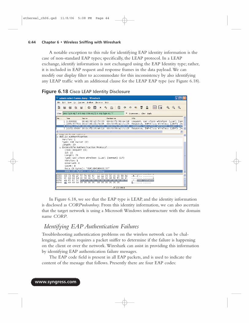
A notable exception to this rule for identifying EAP identity information is thecase of non-standard EAP types; specifically, the LEAP protocol. In a LEAPexchange, identify information is not exchanged using the EAP Identity type; rather,it is included in EAP request and response frames in the data payload. We canmodify our display filter to accommodate for this inconsistency by also identifyingany LEAP traffic with an additional clause for the LEAP EAP type (see Figure 6.18).
In Figure 6.18, we see that the EAP type is LEAP, and the identity informationis disclosed as CORP\ndoanhuy. From this identity information, we can also ascertainthat the target network is using a Microsoft Windows infrastructure with the domainname CORP.
Identifying EAP Authentication FailuresTroubleshooting authentication problems on the wireless network can be chal-lenging, and often requires a packet sniffer to determine if the failure is happeningon the client or over the network. Wireshark can assist in providing this informationby identifying EAP authentication failure messages.
The EAP code field is present in all EAP packets, and is used to indicate thecontent of the message that follows. Presently there are four EAP codes:
www.syngress.com
6:44 Chapter 6 • Wireless Sniffing with Wireshark
Figure 6.18 Cisco LEAP Identity Disclosure
ethereal_ch06.qxd 11/8/06 5:08 PM Page 44
■ Code 1 - EAP Request A value of 1 in the EAP Code field indicatesthat the EAP frame is requesting information from the recipient.This canbe identity information, encryption negotiation content, or a response-to-challenge text.
■ Code 2 - EAP Response A value of 2 in the EAP Code field indicatesthat the EAP frame is responding to an EAP Request frame.
■ Code 3 - EAP Success A value of 3 in the EAP Code field indicatesthat the previous EAP Response was successful.This is primarily used as aresponse to authentication messages.
■ Code 4 - EAP Failure A value of 4 in the EAP Code field indicates thatthe previous EAP Response failed authentication.
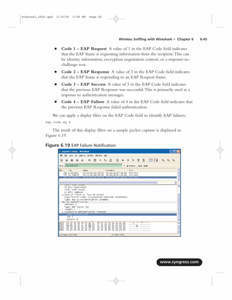
We can apply a display filter on the EAP Code field to identify EAP failures:
eap.code eq 4
The result of this display filter on a sample packet capture is displayed inFigure 6.19.
www.syngress.com
Wireless Sniffing with Wireshark • Chapter 6 6:45
Figure 6.19 EAP Failure Notification
ethereal_ch06.qxd 11/8/06 5:08 PM Page 45
In Figure 6.19, we can see three authentication failures at approximately 8 sec-onds and 7 seconds apart. We can also see that the From DS bit is set in the IEEE802.11 header, indicating that the failure message is coming from the AP. From this,we can determine that the failure message is coming from the client system, notfrom the network.
Identifying Key Negotiation PropertiesSome EAP methods negotiate a Transport Layer Security (TLS) tunnel beforeexchanging authentication information to protect weak authentication protocol data.In order to establish the TLS tunnel, at least one digital certificate is transmitted fromthe AP to the station. We can use Wireshark to examine this certificate information,and possibly determine other sensitive information about the network including theorganization name and address.
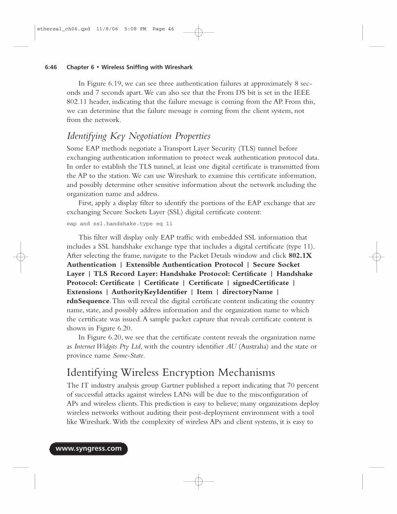
First, apply a display filter to identify the portions of the EAP exchange that areexchanging Secure Sockets Layer (SSL) digital certificate content:
eap and ssl.handshake.type eq 11
This filter will display only EAP traffic with embedded SSL information thatincludes a SSL handshake exchange type that includes a digital certificate (type 11).After selecting the frame, navigate to the Packet Details window and click 802.1XAuthentication | Extensible Authentication Protocol | Secure SocketLayer | TLS Record Layer: Handshake Protocol: Certificate | HandshakeProtocol: Certificate | Certificate | Certificate | signedCertificate |Extensions | AuthorityKeyIdentifier | Item | directoryName |rdnSequence.This will reveal the digital certificate content indicating the countryname, state, and possibly address information and the organization name to whichthe certificate was issued.A sample packet capture that reveals certificate content isshown in Figure 6.20.
In Figure 6.20, we see that the certificate content reveals the organization nameas Internet Widgits Pty Ltd, with the country identifier AU (Australia) and the state orprovince name Some-State.
Identifying Wireless Encryption MechanismsThe IT industry analysis group Gartner published a report indicating that 70 percentof successful attacks against wireless LANs will be due to the misconfiguration ofAPs and wireless clients.This prediction is easy to believe; many organizations deploywireless networks without auditing their post-deployment environment with a toollike Wireshark. With the complexity of wireless APs and client systems, it is easy to
www.syngress.com
6:46 Chapter 6 • Wireless Sniffing with Wireshark
ethereal_ch06.qxd 11/8/06 5:08 PM Page 46
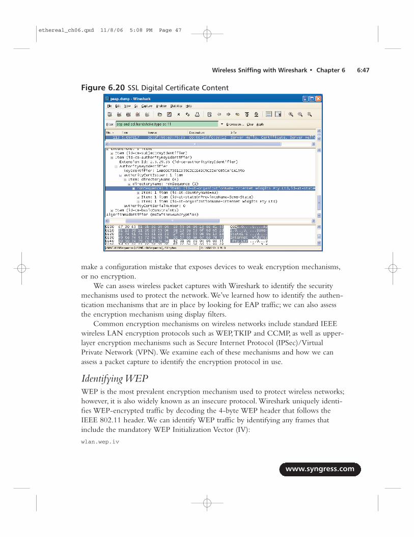
make a configuration mistake that exposes devices to weak encryption mechanisms,or no encryption.
We can assess wireless packet captures with Wireshark to identify the securitymechanisms used to protect the network. We’ve learned how to identify the authen-tication mechanisms that are in place by looking for EAP traffic; we can also assessthe encryption mechanism using display filters.
Common encryption mechanisms on wireless networks include standard IEEEwireless LAN encryption protocols such as WEP,TKIP and CCMP, as well as upper-layer encryption mechanisms such as Secure Internet Protocol (IPSec)/VirtualPrivate Network (VPN). We examine each of these mechanisms and how we canassess a packet capture to identify the encryption protocol in use.
Identifying WEPWEP is the most prevalent encryption mechanism used to protect wireless networks;however, it is also widely known as an insecure protocol. Wireshark uniquely identi-fies WEP-encrypted traffic by decoding the 4-byte WEP header that follows theIEEE 802.11 header. We can identify WEP traffic by identifying any frames thatinclude the mandatory WEP Initialization Vector (IV):
wlan.wep.iv
www.syngress.com
Wireless Sniffing with Wireshark • Chapter 6 6:47
Figure 6.20 SSL Digital Certificate Content
ethereal_ch06.qxd 11/8/06 5:08 PM Page 47
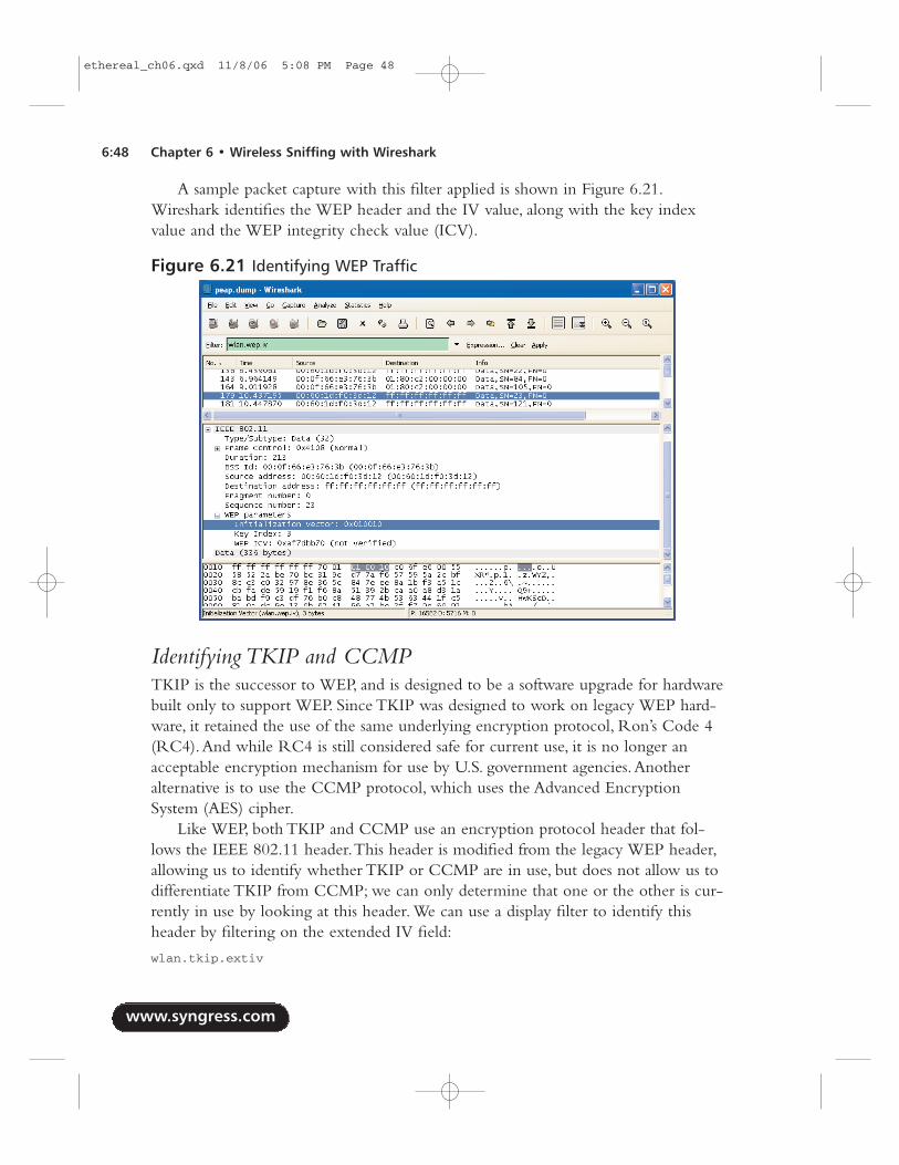
A sample packet capture with this filter applied is shown in Figure 6.21.Wireshark identifies the WEP header and the IV value, along with the key indexvalue and the WEP integrity check value (ICV).
Identifying TKIP and CCMPTKIP is the successor to WEP, and is designed to be a software upgrade for hardwarebuilt only to support WEP. Since TKIP was designed to work on legacy WEP hard-ware, it retained the use of the same underlying encryption protocol, Ron’s Code 4(RC4).And while RC4 is still considered safe for current use, it is no longer anacceptable encryption mechanism for use by U.S. government agencies.Anotheralternative is to use the CCMP protocol, which uses the Advanced EncryptionSystem (AES) cipher.
Like WEP, both TKIP and CCMP use an encryption protocol header that fol-lows the IEEE 802.11 header.This header is modified from the legacy WEP header,allowing us to identify whether TKIP or CCMP are in use, but does not allow us todifferentiate TKIP from CCMP; we can only determine that one or the other is cur-rently in use by looking at this header. We can use a display filter to identify thisheader by filtering on the extended IV field:
wlan.tkip.extiv
www.syngress.com
6:48 Chapter 6 • Wireless Sniffing with Wireshark
Figure 6.21 Identifying WEP Traffic
ethereal_ch06.qxd 11/8/06 5:08 PM Page 48
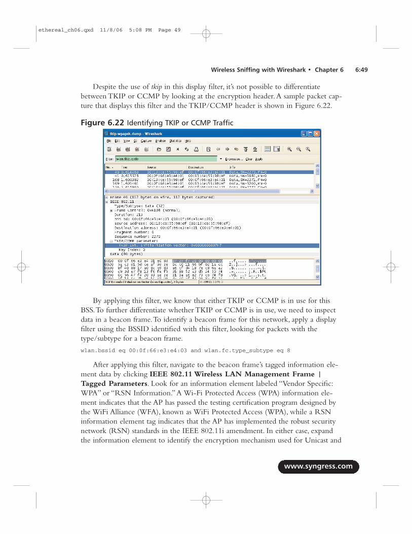
Despite the use of tkip in this display filter, it’s not possible to differentiatebetween TKIP or CCMP by looking at the encryption header.A sample packet cap-ture that displays this filter and the TKIP/CCMP header is shown in Figure 6.22.
By applying this filter, we know that either TKIP or CCMP is in use for thisBSS.To further differentiate whether TKIP or CCMP is in use, we need to inspectdata in a beacon frame.To identify a beacon frame for this network, apply a displayfilter using the BSSID identified with this filter, looking for packets with thetype/subtype for a beacon frame.
wlan.bssid eq 00:0f:66:e3:e4:03 and wlan.fc.type_subtype eq 8
After applying this filter, navigate to the beacon frame’s tagged information ele-ment data by clicking IEEE 802.11 Wireless LAN Management Frame |Tagged Parameters. Look for an information element labeled “Vendor Specific:WPA” or “RSN Information.”A Wi-Fi Protected Access (WPA) information ele-ment indicates that the AP has passed the testing certification program designed bythe WiFi Alliance (WFA), known as WiFi Protected Access (WPA), while a RSNinformation element tag indicates that the AP has implemented the robust securitynetwork (RSN) standards in the IEEE 802.11i amendment. In either case, expandthe information element to identify the encryption mechanism used for Unicast and
www.syngress.com
Wireless Sniffing with Wireshark • Chapter 6 6:49
Figure 6.22 Identifying TKIP or CCMP Traffic
ethereal_ch06.qxd 11/8/06 5:08 PM Page 49
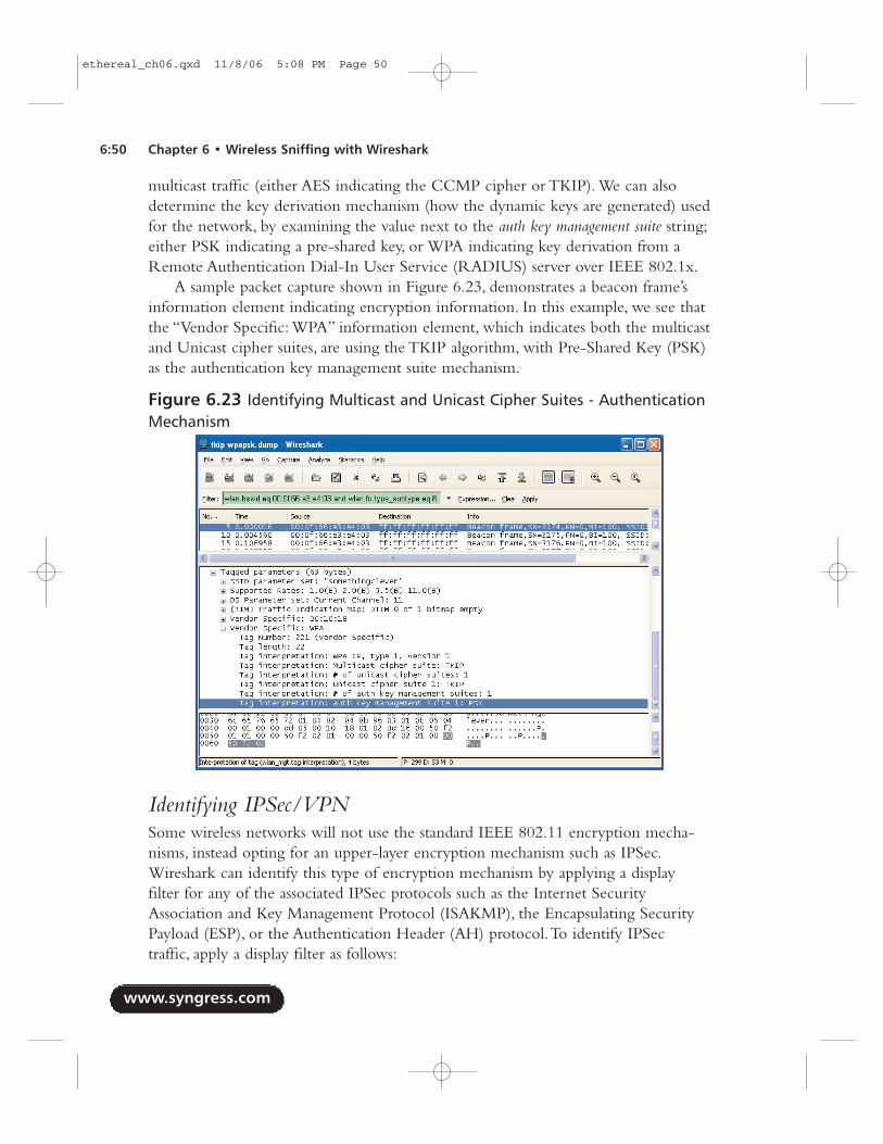
multicast traffic (either AES indicating the CCMP cipher or TKIP). We can alsodetermine the key derivation mechanism (how the dynamic keys are generated) usedfor the network, by examining the value next to the auth key management suite string;either PSK indicating a pre-shared key, or WPA indicating key derivation from aRemote Authentication Dial-In User Service (RADIUS) server over IEEE 802.1x.
A sample packet capture shown in Figure 6.23, demonstrates a beacon frame’sinformation element indicating encryption information. In this example, we see thatthe “Vendor Specific: WPA” information element, which indicates both the multicastand Unicast cipher suites, are using the TKIP algorithm, with Pre-Shared Key (PSK)as the authentication key management suite mechanism.
Identifying IPSec/VPNSome wireless networks will not use the standard IEEE 802.11 encryption mecha-nisms, instead opting for an upper-layer encryption mechanism such as IPSec.Wireshark can identify this type of encryption mechanism by applying a displayfilter for any of the associated IPSec protocols such as the Internet SecurityAssociation and Key Management Protocol (ISAKMP), the Encapsulating SecurityPayload (ESP), or the Authentication Header (AH) protocol.To identify IPSectraffic, apply a display filter as follows:
www.syngress.com
6:50 Chapter 6 • Wireless Sniffing with Wireshark
Figure 6.23 Identifying Multicast and Unicast Cipher Suites - AuthenticationMechanism
ethereal_ch06.qxd 11/8/06 5:08 PM Page 50
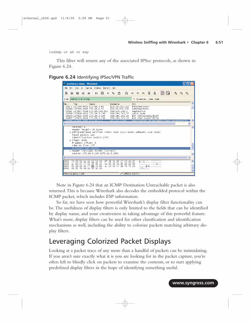
isakmp or ah or esp
This filter will return any of the associated IPSec protocols, as shown inFigure 6.24.
Note in Figure 6.24 that an ICMP Destination Unreachable packet is alsoreturned.This is because Wireshark also decodes the embedded protocol within theICMP packet, which includes ESP information.
So far, we have seen how powerful Wireshark’s display filter functionality canbe.The usefulness of display filters is only limited to the fields that can be identifiedby display name, and your creativeness in taking advantage of this powerful feature.What’s more, display filters can be used for other classification and identificationmechanisms as well, including the ability to colorize packets matching arbitrary dis-play filters.
Leveraging Colorized Packet DisplaysLooking at a packet trace of any more than a handful of packets can be intimidating.If you aren’t sure exactly what it is you are looking for in the packet capture, you’reoften left to blindly click on packets to examine the contents, or to start applyingpredefined display filters in the hope of identifying something useful.
www.syngress.com
Wireless Sniffing with Wireshark • Chapter 6 6:51
Figure 6.24 Identifying IPSec/VPN Traffic
ethereal_ch06.qxd 11/8/06 5:08 PM Page 51
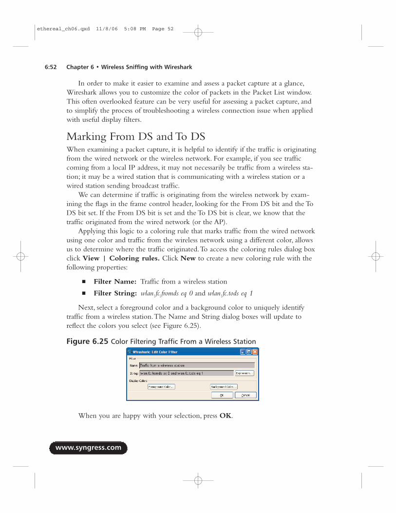
In order to make it easier to examine and assess a packet capture at a glance,Wireshark allows you to customize the color of packets in the Packet List window.This often overlooked feature can be very useful for assessing a packet capture, andto simplify the process of troubleshooting a wireless connection issue when appliedwith useful display filters.
Marking From DS and To DSWhen examining a packet capture, it is helpful to identify if the traffic is originatingfrom the wired network or the wireless network. For example, if you see trafficcoming from a local IP address, it may not necessarily be traffic from a wireless sta-tion; it may be a wired station that is communicating with a wireless station or awired station sending broadcast traffic.
We can determine if traffic is originating from the wireless network by exam-ining the flags in the frame control header, looking for the From DS bit and the ToDS bit set. If the From DS bit is set and the To DS bit is clear, we know that thetraffic originated from the wired network (or the AP).
Applying this logic to a coloring rule that marks traffic from the wired networkusing one color and traffic from the wireless network using a different color, allowsus to determine where the traffic originated.To access the coloring rules dialog boxclick View | Coloring rules. Click New to create a new coloring rule with thefollowing properties:
■ Filter Name: Traffic from a wireless station
■ Filter String: wlan.fc.fromds eq 0 and wlan.fc.tods eq 1
Next, select a foreground color and a background color to uniquely identifytraffic from a wireless station.The Name and String dialog boxes will update toreflect the colors you select (see Figure 6.25).
When you are happy with your selection, press OK.
www.syngress.com
6:52 Chapter 6 • Wireless Sniffing with Wireshark
Figure 6.25 Color Filtering Traffic From a Wireless Station
ethereal_ch06.qxd 11/8/06 5:08 PM Page 52
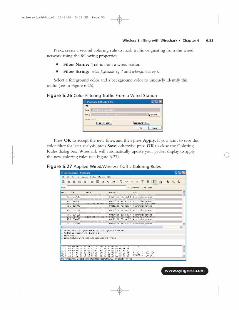
Next, create a second coloring rule to mark traffic originating from the wirednetwork using the following properties:
■ Filter Name: Traffic from a wired station
■ Filter String: wlan.fc.fromds eq 1 and wlan.fc.tods eq 0
Select a foreground color and a background color to uniquely identify thistraffic (see in Figure 6.26).
Press OK to accept the new filter, and then press Apply. If you want to save thiscolor filter for later analysis, press Save; otherwise press OK to close the ColoringRules dialog box. Wireshark will automatically update your packet display to applythe new coloring rules (see Figure 6.27).
www.syngress.com
Wireless Sniffing with Wireshark • Chapter 6 6:53
Figure 6.26 Color Filtering Traffic From a Wired Station
Figure 6.27 Applied Wired/Wireless Traffic Coloring Rules
ethereal_ch06.qxd 11/8/06 5:08 PM Page 53
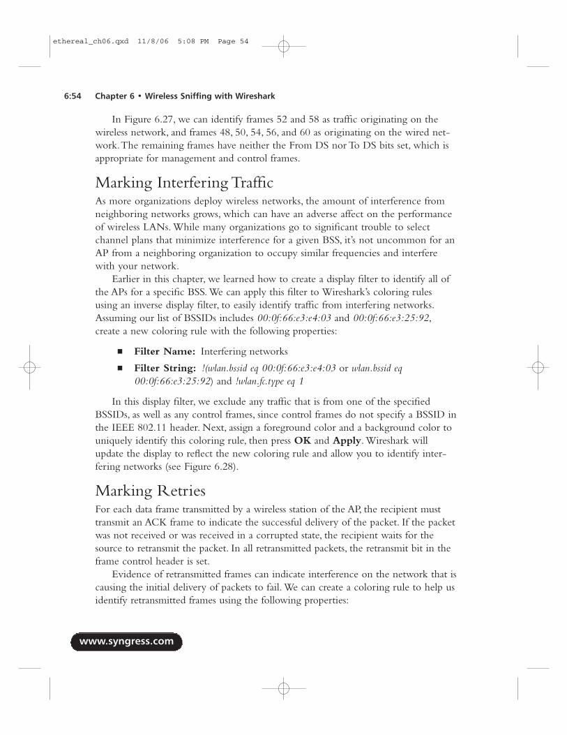
In Figure 6.27, we can identify frames 52 and 58 as traffic originating on thewireless network, and frames 48, 50, 54, 56, and 60 as originating on the wired net-work.The remaining frames have neither the From DS nor To DS bits set, which isappropriate for management and control frames.
Marking Interfering TrafficAs more organizations deploy wireless networks, the amount of interference fromneighboring networks grows, which can have an adverse affect on the performanceof wireless LANs. While many organizations go to significant trouble to selectchannel plans that minimize interference for a given BSS, it’s not uncommon for anAP from a neighboring organization to occupy similar frequencies and interferewith your network.
Earlier in this chapter, we learned how to create a display filter to identify all ofthe APs for a specific BSS. We can apply this filter to Wireshark’s coloring rulesusing an inverse display filter, to easily identify traffic from interfering networks.Assuming our list of BSSIDs includes 00:0f:66:e3:e4:03 and 00:0f:66:e3:25:92,create a new coloring rule with the following properties:
■ Filter Name: Interfering networks
■ Filter String: !(wlan.bssid eq 00:0f:66:e3:e4:03 or wlan.bssid eq00:0f:66:e3:25:92) and !wlan.fc.type eq 1
In this display filter, we exclude any traffic that is from one of the specifiedBSSIDs, as well as any control frames, since control frames do not specify a BSSID inthe IEEE 802.11 header. Next, assign a foreground color and a background color touniquely identify this coloring rule, then press OK and Apply. Wireshark willupdate the display to reflect the new coloring rule and allow you to identify inter-fering networks (see Figure 6.28).
Marking RetriesFor each data frame transmitted by a wireless station of the AP, the recipient musttransmit an ACK frame to indicate the successful delivery of the packet. If the packetwas not received or was received in a corrupted state, the recipient waits for thesource to retransmit the packet. In all retransmitted packets, the retransmit bit in theframe control header is set.
Evidence of retransmitted frames can indicate interference on the network that iscausing the initial delivery of packets to fail. We can create a coloring rule to help usidentify retransmitted frames using the following properties:
www.syngress.com
6:54 Chapter 6 • Wireless Sniffing with Wireshark
ethereal_ch06.qxd 11/8/06 5:08 PM Page 54
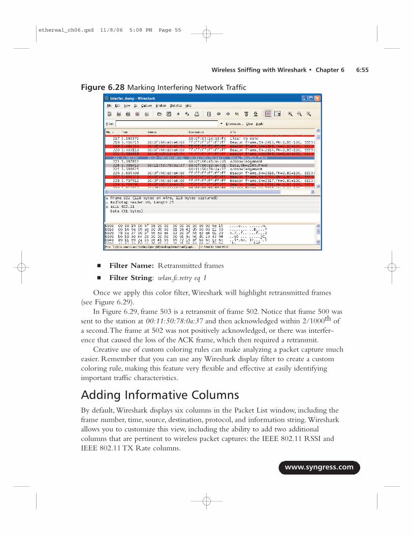
■ Filter Name: Retransmitted frames
■ Filter String: wlan.fc.retry eq 1
Once we apply this color filter, Wireshark will highlight retransmitted frames(see Figure 6.29).
In Figure 6.29, frame 503 is a retransmit of frame 502. Notice that frame 500 wassent to the station at 00:11:50:78:0a:37 and then acknowledged within 2/1000th ofa second.The frame at 502 was not positively acknowledged, or there was interfer-ence that caused the loss of the ACK frame, which then required a retransmit.
Creative use of custom coloring rules can make analyzing a packet capture mucheasier. Remember that you can use any Wireshark display filter to create a customcoloring rule, making this feature very flexible and effective at easily identifyingimportant traffic characteristics.
Adding Informative ColumnsBy default, Wireshark displays six columns in the Packet List window, including theframe number, time, source, destination, protocol, and information string. Wiresharkallows you to customize this view, including the ability to add two additionalcolumns that are pertinent to wireless packet captures: the IEEE 802.11 RSSI andIEEE 802.11 TX Rate columns.
www.syngress.com
Wireless Sniffing with Wireshark • Chapter 6 6:55
Figure 6.28 Marking Interfering Network Traffic
ethereal_ch06.qxd 11/8/06 5:08 PM Page 55
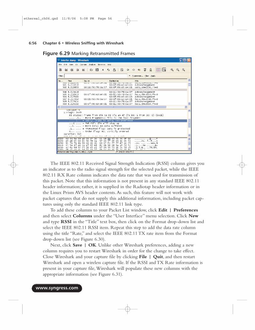
The IEEE 802.11 Received Signal Strength Indication (RSSI) column gives youan indicator as to the radio signal strength for the selected packet, while the IEEE802.11 RX Rate column indicates the data rate that was used for transmission ofthis packet. Note that this information is not present in any standard IEEE 802.11header information; rather, it is supplied in the Radiotap header information or inthe Linux Prism AVS header contents.As such, this feature will not work withpacket captures that do not supply this additional information, including packet cap-tures using only the standard IEEE 802.11 link type.
To add these columns to your Packet List window, click Edit | Preferencesand then select Columns under the “User Interface” menu selection. Click Newand type RSSI in the “Title” text box, then click on the Format drop-down list andselect the IEEE 802.11 RSSI item. Repeat this step to add the data rate columnusing the title “Rate,” and select the IEEE 802.11 TX rate item from the Formatdrop-down list (see Figure 6.30).
Next, click Save | OK. Unlike other Wireshark preferences, adding a newcolumn requires you to restart Wireshark in order for the change to take effect.Close Wireshark and your capture file by clicking File | Quit, and then restartWireshark and open a wireless capture file. If the RSSI and TX Rate information ispresent in your capture file, Wireshark will populate these new columns with theappropriate information (see Figure 6.31).
www.syngress.com
6:56 Chapter 6 • Wireless Sniffing with Wireshark
Figure 6.29 Marking Retransmitted Frames
ethereal_ch06.qxd 11/8/06 5:08 PM Page 56
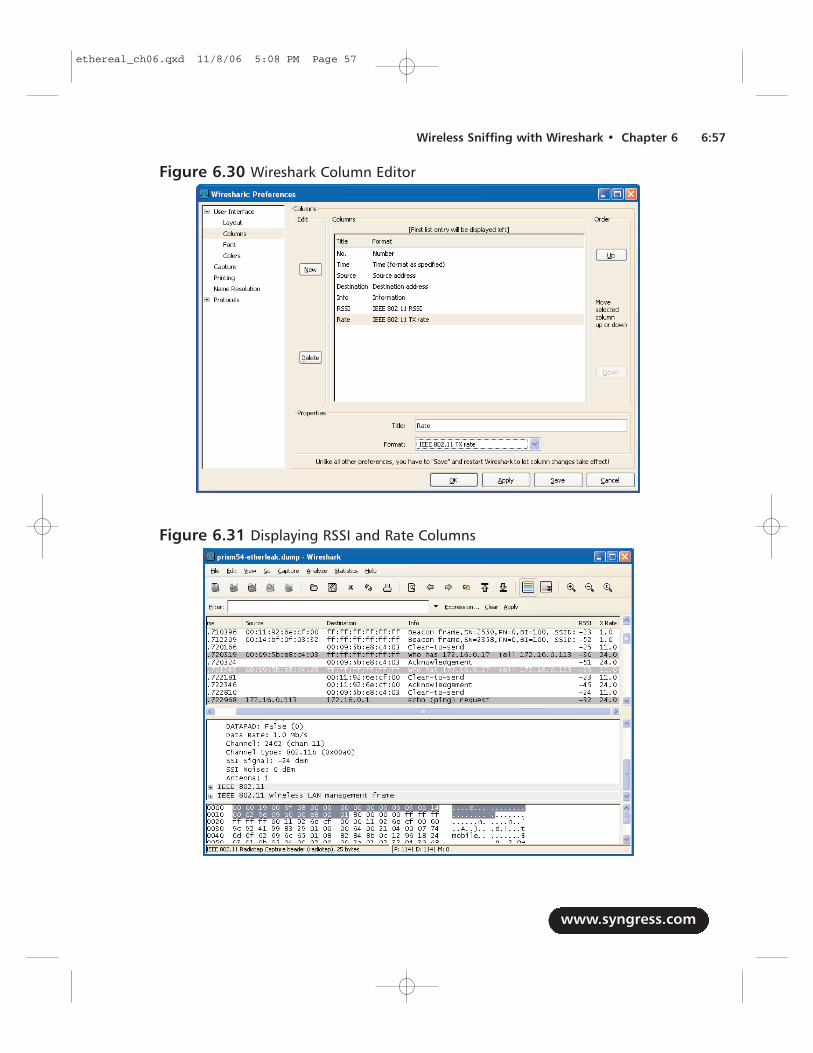
www.syngress.com
Wireless Sniffing with Wireshark • Chapter 6 6:57
Figure 6.30 Wireshark Column Editor
Figure 6.31 Displaying RSSI and Rate Columns
ethereal_ch06.qxd 11/8/06 5:08 PM Page 57
The ability to view these fields can be useful for troubleshooting and wirelessintrusion detection purposes.As a station gets farther away from the AP, the TX ratefor data frames drops in order to sustain connectivity to an AP. Observing a largenumber of stations transmitting below the optimal 11 Megabits per second (Mbps)for IEEE 802.11b networks or 54 Mbps for IEEE 802.11g or IEEE 802.11a net-works, is an indicator of poor AP selection on behalf of the client (there may be amore optimal AP available), or poor deployment or configuration of APs. Inspectingthe RSSI information allows you to identify drops in the signal strength for a client,which can be an indicator of interference or other Radio Frequency (RF) loss char-acteristics, which can also affect network performance.
Decrypting TrafficOne of the challenges of wireless traffic analysis is the ability to inspect the contentsof encrypted data frames. While Wireshark has the ability to decode many differentNetwork layer and higher protocols, encrypted traffic limits your ability to analyzepackets and troubleshoot network problems.
Fortunately, Wireshark offers some options to analyze WEP-encrypted data.When configured with the appropriate WEP key, Wireshark can automaticallydecrypt WEP-encrypted data and dissect the plaintext contents of these frames.Thisallows you to use display filters, coloring rules, and all other Wireshark features onthe decrypted frame contents.
In order for Wireshark to decrypt the contents of WEP-encrypted packets, itmust be given the appropriate WEP key for the network. Wireshark does not assistyou in breaking WEP keys or attacking the WEP protocol. If you are the legitimateadministrator of the wireless network, you can configure Wireshark with the appro-priate WEP key by clicking Edit | Preferences, and then expanding the“Protocols” menu and selecting IEEE 802.11. In the Wireshark Preferences window,supply one or more WEP keys in hexadecimal form separated by colons (see Figure6.32).After entering one or more WEP keys, select the Enable Decryptioncheckbox. Click OK when finished.
Wireshark will automatically apply the WEP key to each WEP-encrypted packetin the capture. If the packet decrypts properly, Wireshark will add a tabbed view tothe Packet Bytes window, allowing you to choose between the encrypted anddecrypted views. Wireshark will also dissect the contents of the unencrypted frame,allowing you to view the embedded protocol information as if the frame wereunencrypted in its original state.
Unfortunately, at the time of this writing, Wireshark does not supportdecrypting TKIP or CCMP packets. However, you can use external tools such as the
www.syngress.com
6:58 Chapter 6 • Wireless Sniffing with Wireshark
ethereal_ch06.qxd 11/8/06 5:08 PM Page 58
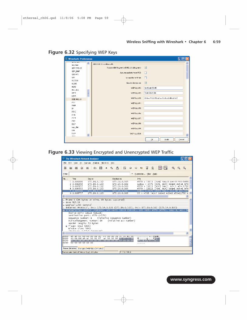
www.syngress.com
Wireless Sniffing with Wireshark • Chapter 6 6:59
Figure 6.32 Specifying WEP Keys
Figure 6.33 Viewing Encrypted and Unencrypted WEP Traffic
ethereal_ch06.qxd 11/8/06 5:08 PM Page 59
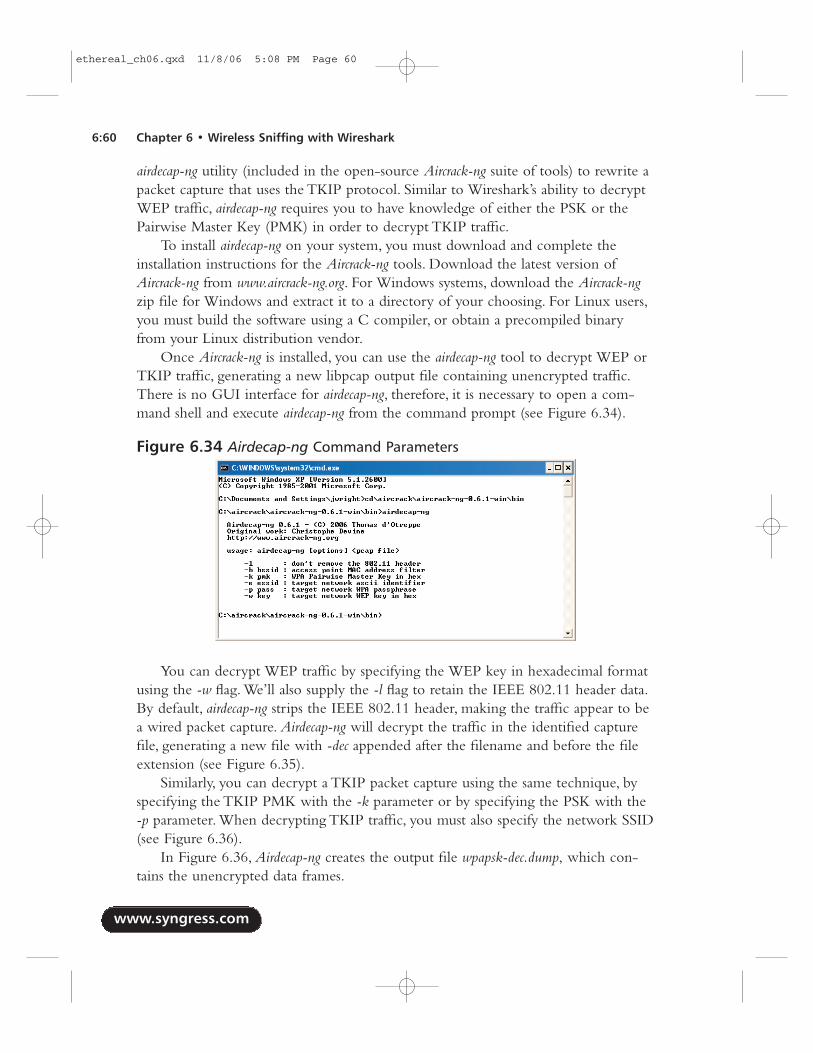
airdecap-ng utility (included in the open-source Aircrack-ng suite of tools) to rewrite apacket capture that uses the TKIP protocol. Similar to Wireshark’s ability to decryptWEP traffic, airdecap-ng requires you to have knowledge of either the PSK or thePairwise Master Key (PMK) in order to decrypt TKIP traffic.
To install airdecap-ng on your system, you must download and complete theinstallation instructions for the Aircrack-ng tools. Download the latest version ofAircrack-ng from www.aircrack-ng.org. For Windows systems, download the Aircrack-ngzip file for Windows and extract it to a directory of your choosing. For Linux users,you must build the software using a C compiler, or obtain a precompiled binaryfrom your Linux distribution vendor.
Once Aircrack-ng is installed, you can use the airdecap-ng tool to decrypt WEP orTKIP traffic, generating a new libpcap output file containing unencrypted traffic.There is no GUI interface for airdecap-ng, therefore, it is necessary to open a com-mand shell and execute airdecap-ng from the command prompt (see Figure 6.34).
You can decrypt WEP traffic by specifying the WEP key in hexadecimal formatusing the -w flag. We’ll also supply the -l flag to retain the IEEE 802.11 header data.By default, airdecap-ng strips the IEEE 802.11 header, making the traffic appear to bea wired packet capture. Airdecap-ng will decrypt the traffic in the identified capturefile, generating a new file with -dec appended after the filename and before the fileextension (see Figure 6.35).
Similarly, you can decrypt a TKIP packet capture using the same technique, byspecifying the TKIP PMK with the -k parameter or by specifying the PSK with the-p parameter. When decrypting TKIP traffic, you must also specify the network SSID(see Figure 6.36).
In Figure 6.36, Airdecap-ng creates the output file wpapsk-dec.dump, which con-tains the unencrypted data frames.
www.syngress.com
6:60 Chapter 6 • Wireless Sniffing with Wireshark
Figure 6.34 Airdecap-ng Command Parameters
ethereal_ch06.qxd 11/8/06 5:08 PM Page 60
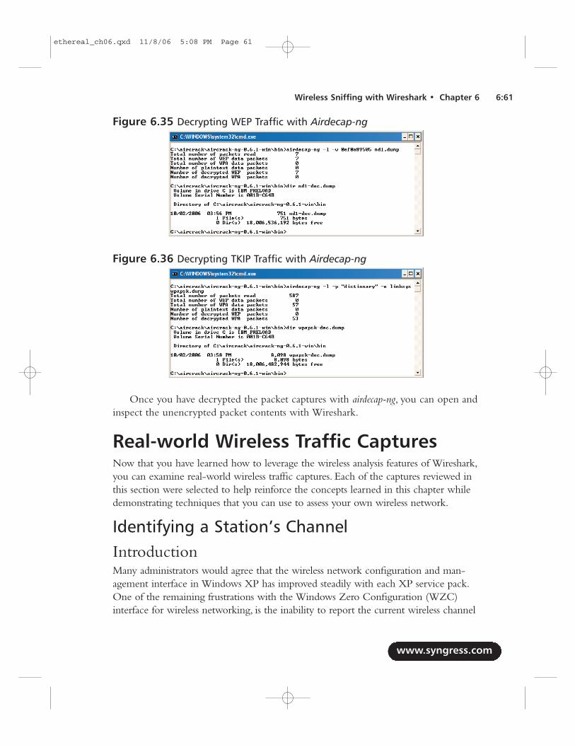
Once you have decrypted the packet captures with airdecap-ng, you can open andinspect the unencrypted packet contents with Wireshark.
Real-world Wireless Traffic CapturesNow that you have learned how to leverage the wireless analysis features of Wireshark,you can examine real-world wireless traffic captures. Each of the captures reviewed inthis section were selected to help reinforce the concepts learned in this chapter whiledemonstrating techniques that you can use to assess your own wireless network.
Identifying a Station’s ChannelIntroductionMany administrators would agree that the wireless network configuration and man-agement interface in Windows XP has improved steadily with each XP service pack.One of the remaining frustrations with the Windows Zero Configuration (WZC)interface for wireless networking, is the inability to report the current wireless channel
www.syngress.com
Wireless Sniffing with Wireshark • Chapter 6 6:61
Figure 6.35 Decrypting WEP Traffic with Airdecap-ng
Figure 6.36 Decrypting TKIP Traffic with Airdecap-ng
ethereal_ch06.qxd 11/8/06 5:08 PM Page 61
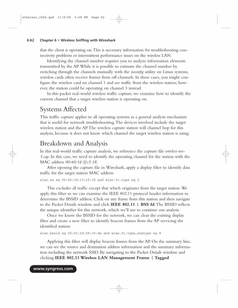
that the client is operating on.This is necessary information for troubleshooting con-nectivity problems or intermittent performance issues on the wireless LAN.
Identifying the channel number requires you to analyze information elementstransmitted by the AP. While it is possible to estimate the channel number byswitching through the channels manually with the iwconfig utility on Linux systems,wireless cards often receive frames from off-channels. In these cases, you might con-figure the wireless card on channel 1 and see traffic from the wireless station; how-ever, the station could be operating on channel 3 instead.
In this packet real-world wireless traffic capture, we examine how to identify thecurrent channel that a target wireless station is operating on.
Systems AffectedThis traffic capture applies to all operating systems as a general analysis mechanismthat is useful for network troubleshooting.The devices involved include the targetwireless station and the AP.The wireless capture station will channel hop for thisanalysis, because it does not know which channel the target wireless station is using.
Breakdown and AnalysisIn this real-world traffic capture analysis, we reference the capture file wireless-rwc-1.cap. In this case, we need to identify the operating channel for the station with theMAC address 00:60:1d:1f:c5:18.
After opening the capture file in Wireshark, apply a display filter to identify datatraffic for the target station MAC address:
wlan.sa eq 00:60:1d:1f:c5:18 and wlan.fc.type eq 2
This excludes all traffic except that which originates from the target station. Weapply this filter so we can examine the IEEE 802.11 protocol header information todetermine the BSSID address. Click on any frame from this station and then navigateto the Packet Details window and click IEEE 802.11 | BSS Id.The BSSID reflectsthe unique identifier for this network, which we’ll use to continue our analysis.
Once we know the BSSID for the network, we can clear the existing displayfilter and create a new filter to identify beacon frames from the AP servicing theidentified station:
wlan.bssid eq 00:02:2d:09:c0:da and wlan.fc.type_subtype eq 8
Applying this filter will display beacon frames from the AP. On the summary line,we can see the source and destination address information and the summary informa-tion including the network SSID. By navigating to the Packet Details window andclicking IEEE 802.11 Wireless LAN Management Frame | Tagged
www.syngress.com
6:62 Chapter 6 • Wireless Sniffing with Wireshark
ethereal_ch06.qxd 11/8/06 5:08 PM Page 62
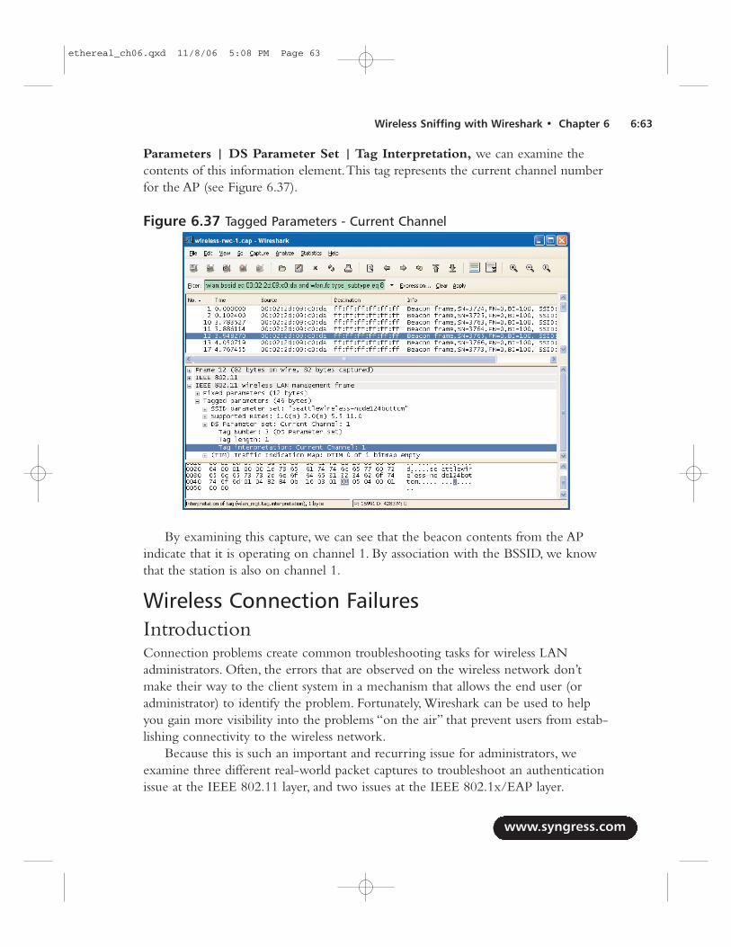
Parameters | DS Parameter Set | Tag Interpretation, we can examine thecontents of this information element.This tag represents the current channel numberfor the AP (see Figure 6.37).
By examining this capture, we can see that the beacon contents from the APindicate that it is operating on channel 1. By association with the BSSID, we knowthat the station is also on channel 1.
Wireless Connection FailuresIntroductionConnection problems create common troubleshooting tasks for wireless LANadministrators. Often, the errors that are observed on the wireless network don’tmake their way to the client system in a mechanism that allows the end user (oradministrator) to identify the problem. Fortunately, Wireshark can be used to helpyou gain more visibility into the problems “on the air” that prevent users from estab-lishing connectivity to the wireless network.
Because this is such an important and recurring issue for administrators, weexamine three different real-world packet captures to troubleshoot an authenticationissue at the IEEE 802.11 layer, and two issues at the IEEE 802.1x/EAP layer.
www.syngress.com
Wireless Sniffing with Wireshark • Chapter 6 6:63
Figure 6.37 Tagged Parameters - Current Channel
ethereal_ch06.qxd 11/8/06 5:08 PM Page 63
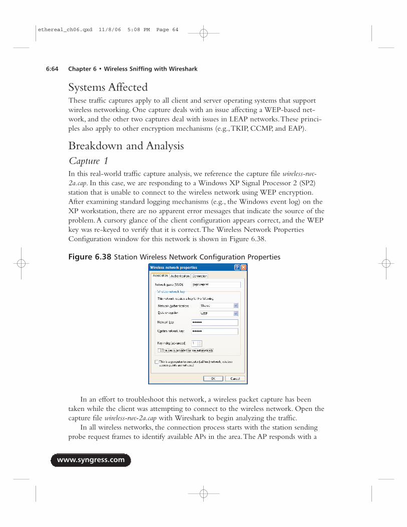
Systems AffectedThese traffic captures apply to all client and server operating systems that supportwireless networking. One capture deals with an issue affecting a WEP-based net-work, and the other two captures deal with issues in LEAP networks.These princi-ples also apply to other encryption mechanisms (e.g.,TKIP, CCMP, and EAP).
Breakdown and AnalysisCapture 1In this real-world traffic capture analysis, we reference the capture file wireless-rwc-2a.cap. In this case, we are responding to a Windows XP Signal Processor 2 (SP2)station that is unable to connect to the wireless network using WEP encryption.After examining standard logging mechanisms (e.g., the Windows event log) on theXP workstation, there are no apparent error messages that indicate the source of theproblem.A cursory glance of the client configuration appears correct, and the WEPkey was re-keyed to verify that it is correct.The Wireless Network PropertiesConfiguration window for this network is shown in Figure 6.38.
In an effort to troubleshoot this network, a wireless packet capture has beentaken while the client was attempting to connect to the wireless network. Open thecapture file wireless-rwc-2a.cap with Wireshark to begin analyzing the traffic.
In all wireless networks, the connection process starts with the station sendingprobe request frames to identify available APs in the area.The AP responds with a
www.syngress.com
6:64 Chapter 6 • Wireless Sniffing with Wireshark
Figure 6.38 Station Wireless Network Configuration Properties
ethereal_ch06.qxd 11/8/06 5:08 PM Page 64
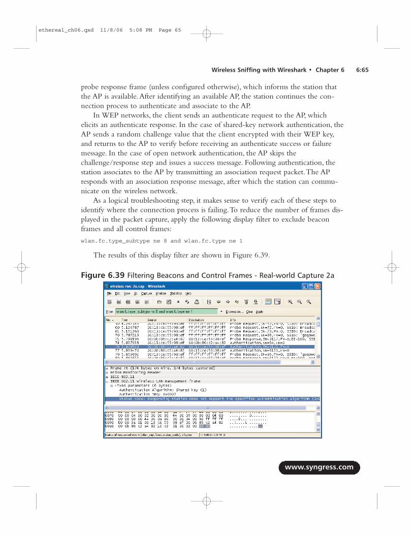
probe response frame (unless configured otherwise), which informs the station thatthe AP is available.After identifying an available AP, the station continues the con-nection process to authenticate and associate to the AP.
In WEP networks, the client sends an authenticate request to the AP, whichelicits an authenticate response. In the case of shared-key network authentication, theAP sends a random challenge value that the client encrypted with their WEP key,and returns to the AP to verify before receiving an authenticate success or failuremessage. In the case of open network authentication, the AP skips thechallenge/response step and issues a success message. Following authentication, thestation associates to the AP by transmitting an association request packet.The APresponds with an association response message, after which the station can commu-nicate on the wireless network.
As a logical troubleshooting step, it makes sense to verify each of these steps toidentify where the connection process is failing.To reduce the number of frames dis-played in the packet capture, apply the following display filter to exclude beaconframes and all control frames:
wlan.fc.type_subtype ne 8 and wlan.fc.type ne 1
The results of this display filter are shown in Figure 6.39.
www.syngress.com
Wireless Sniffing with Wireshark • Chapter 6 6:65
Figure 6.39 Filtering Beacons and Control Frames - Real-world Capture 2a
ethereal_ch06.qxd 11/8/06 5:08 PM Page 65
In frame 34, we see the station sending probe requests for the SSID <No currentssid>; another probe request in frame 35 is targeting the broadcast SSID.These repeatwithout response until frame 70, which probes for the gogowepnet SSID, gets aresponse from the AP in the form of a probe response frame.This is appropriatebehavior, because the station needs to know the BSSID and other capability infor-mation contained in the probe response frame before connecting to the AP.
Following the probe response in frames 74, 76, and 77, we see authenticationtraffic. We can tell that frame 77 is a retransmit of frame 76, because the SN (3121)listed in the information column is the same for both packets. We start our detailedanalysis with frame 74; click on this frame and expand the management parametersby clicking IEEE 802.11 Wireless LAN Management Frame | FixedParameters.This will reveal the authentication algorithm as shared key, the authen-tication SN, and the status code. Because this is the first packet in the authenticationexchange, the status code value is irrelevant.
Now that we know the authentication algorithm information that is beingrequested, look at frame 77. In the management parameters information we see theauthentication algorithm is still shared key, but the status code has a message indi-cating “Responding station does not support the specified authentication algorithm.”This error is preventing the client from connecting to the AP.
As a security feature, modern APs using WEP only support open authenticationwith WEP encryption, because shared key authentication introduces additional vul-nerabilities to the network. Since this client is requesting shared-key authentication,the AP is rejecting the request with an error.To resolve this problem, reconfigure theclient system to use open authentication with WEP instead of shared authentication.
Capture 2In this real-world traffic capture analysis, we reference the capture file wireless-rwc-2b.cap.This is another example of a client that is unable to connect to the network. Open thecapture file wireless-rwc-2b.cap and use the same display filter as in the previous capture toexclude beacon frames and control frames from the display:
wlan.fc.type_subtype ne 8 and wlan.fc.type ne 1
The result of this display filter is shown in Figure 6.40.We can identify that the station is connecting to the AP successfully by looking
at the Packet List window Information column. In frames 23 and 25, we see theprobe request and response exchange, followed by two authentication frames.Clicking on frame 29 to select the second authentication frame, and clicking onIEEE 802.11 Wireless LAN Management Frame | Fixed Parameters |Status Code reveals that the authentication exchange was successful.
www.syngress.com
6:66 Chapter 6 • Wireless Sniffing with Wireshark
ethereal_ch06.qxd 11/8/06 5:08 PM Page 66
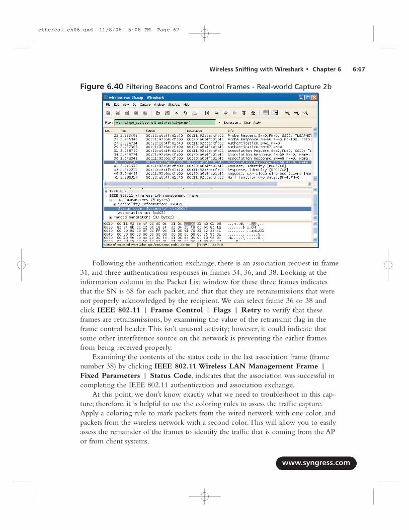
Following the authentication exchange, there is an association request in frame31, and three authentication responses in frames 34, 36, and 38. Looking at theinformation column in the Packet List window for these three frames indicatesthat the SN is 68 for each packet, and that that they are retransmissions that werenot properly acknowledged by the recipient. We can select frame 36 or 38 andclick IEEE 802.11 | Frame Control | Flags | Retry to verify that theseframes are retransmissions, by examining the value of the retransmit flag in theframe control header.This isn’t unusual activity; however, it could indicate thatsome other interference source on the network is preventing the earlier framesfrom being received properly.
Examining the contents of the status code in the last association frame (framenumber 38) by clicking IEEE 802.11 Wireless LAN Management Frame |Fixed Parameters | Status Code, indicates that the association was successful incompleting the IEEE 802.11 authentication and association exchange.
At this point, we don’t know exactly what we need to troubleshoot in this cap-ture; therefore, it is helpful to use the coloring rules to assess the traffic capture.Apply a coloring rule to mark packets from the wired network with one color, andpackets from the wireless network with a second color.This will allow you to easilyassess the remainder of the frames to identify the traffic that is coming from the APor from client systems.
www.syngress.com
Wireless Sniffing with Wireshark • Chapter 6 6:67
Figure 6.40 Filtering Beacons and Control Frames - Real-world Capture 2b
ethereal_ch06.qxd 11/8/06 5:08 PM Page 67
Following the association response frame, we see that the beginning of the EAPauthentication exchange in frame 41 is coming from the AP; this frame is requestingidentity information from the station, which is returned in frame 43 with an identityresponse frame. In frame 46, we see a new EAP request frame indicating that theEAP type is the Cisco LEAP protocol. We can inspect the EAP details of this frameby clicking 802.1X Authentication | Extensible Authentication Protocol.Inspecting the details of this frame, we see that the payload of the EAP packetincludes an 8-byte random value and the name of the user authentication to thenetwork.The 8-byte random value represents the challenge value that must beencrypted and returned by the authenticating station.
Frame 51 indicates a NULL data frame.This frame is not part of the EAPexchange. Rather, it is a mechanism that is used by the station to enter power-con-servation mode while advertising to the AP that it should save any pending trafficfor that station until it returns to the network.This can be confirmed by inspectingthe power management bit in the frame control header, and by clicking IEEE802.11 | Frame Control | Flags | PWR MGT. Since this value is set to 1, weknow that the station is entering power management mode.This is normal activityfor some stations, especially Intel Centrino wireless cards, which are more aggressiveat power conservation than other chipset manufacturers.
The station returns from power conservation mode in frame 66 with an EAPresponse frame.Again, we can inspect the contents of the EAP payload by clicking802.1X Authentication | Extensible Authentication Protocol. In the EAPpayload contents, we see something labeled “Peer Challenge [8] Random Value”; thisis an incorrect representation by Wireshark. Instead of being a peer challenge value,this is the actual peer response. Further, the peer response value is 24 bytes in length,not 8 bytes as indicated.This frame represents the response from the wireless stationfollowing the earlier challenge value.
Following the EAP response from the station, we would normally expect to seean EAP Success message from the AP. In this capture, we see an additional NULLdata frame from the station indicating additional power management activity, fol-lowed by a multicast data frame for the Spanning Tree Protocol (STP) in frames 71and 77, respectively. Instead of an EAP Success message, we see several deauthentica-tion messages from the AP to the wireless client.This indicates that the LEAPauthentication exchange was not successful, and that the AP is notifying the stationthat it has been disconnected from the network.The deauthentication frame is trans-mitted multiple times, because it is not properly acknowledge by the wireless station,possibly because the station is in power conservation mode.
In this packet capture, we see that the station has successfully completed theIEEE 802.11 authentication and association exchange, but was unable to complete
www.syngress.com
6:68 Chapter 6 • Wireless Sniffing with Wireshark
ethereal_ch06.qxd 11/8/06 5:08 PM Page 68
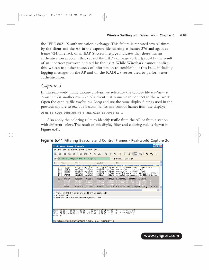
the IEEE 802.1X authentication exchange.This failure is repeated several timesby the client and the AP in the capture file, starting at frames 376 and again atframe 724.The lack of an EAP Success message indicates that there was anauthentication problem that caused the EAP exchange to fail (probably the resultof an incorrect password entered by the user). While Wireshark cannot confirmthis, we can use other sources of information to troubleshoot this issue, includinglogging messages on the AP and on the RADIUS server used to perform userauthentication.
Capture 3In this real-world traffic capture analysis, we reference the capture file wireless-rwc-2c.cap.This is another example of a client that is unable to connect to the network.Open the capture file wireless-rwc-2c.cap and use the same display filter as used in theprevious capture to exclude beacon frames and control frames from the display:
wlan.fc.type_subtype ne 8 and wlan.fc.type ne 1
Also apply the coloring rules to identify traffic from the AP or from a stationwith different colors.The result of this display filter and coloring rule is shown inFigure 6.41.
www.syngress.com
Wireless Sniffing with Wireshark • Chapter 6 6:69
Figure 6.41 Filtering Beacons and Control Frames - Real-world Capture 2c
ethereal_ch06.qxd 11/8/06 5:08 PM Page 69
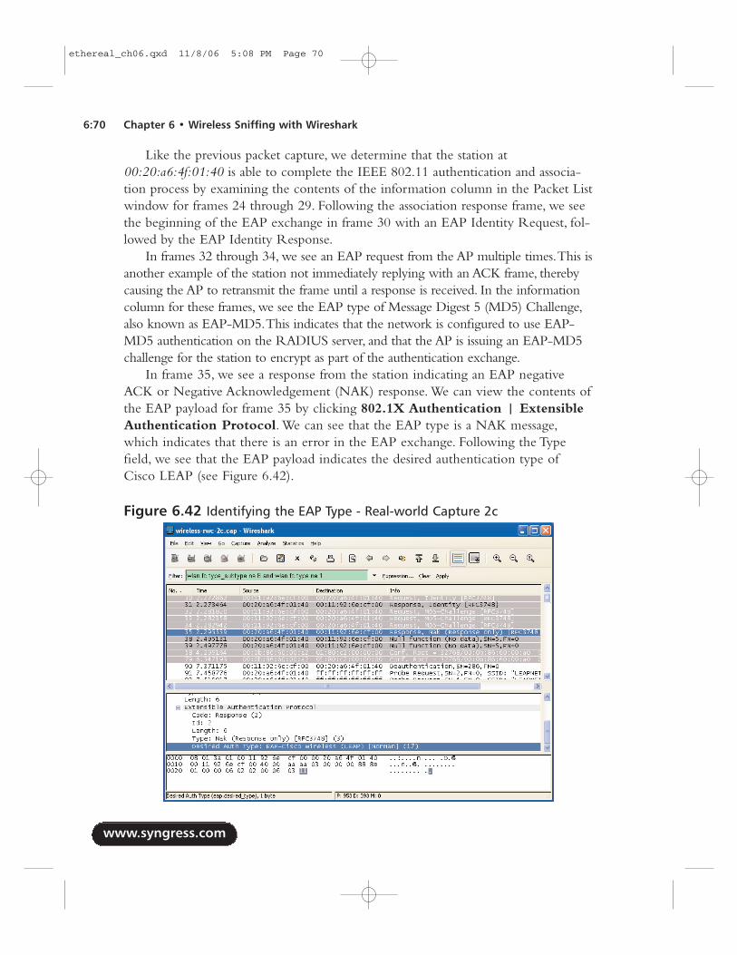
Like the previous packet capture, we determine that the station at00:20:a6:4f:01:40 is able to complete the IEEE 802.11 authentication and associa-tion process by examining the contents of the information column in the Packet Listwindow for frames 24 through 29. Following the association response frame, we seethe beginning of the EAP exchange in frame 30 with an EAP Identity Request, fol-lowed by the EAP Identity Response.
In frames 32 through 34, we see an EAP request from the AP multiple times.This isanother example of the station not immediately replying with an ACK frame, therebycausing the AP to retransmit the frame until a response is received. In the informationcolumn for these frames, we see the EAP type of Message Digest 5 (MD5) Challenge,also known as EAP-MD5.This indicates that the network is configured to use EAP-MD5 authentication on the RADIUS server, and that the AP is issuing an EAP-MD5challenge for the station to encrypt as part of the authentication exchange.
In frame 35, we see a response from the station indicating an EAP negativeACK or Negative Acknowledgement (NAK) response. We can view the contents ofthe EAP payload for frame 35 by clicking 802.1X Authentication | ExtensibleAuthentication Protocol. We can see that the EAP type is a NAK message,which indicates that there is an error in the EAP exchange. Following the Typefield, we see that the EAP payload indicates the desired authentication type ofCisco LEAP (see Figure 6.42).
www.syngress.com
6:70 Chapter 6 • Wireless Sniffing with Wireshark
Figure 6.42 Identifying the EAP Type - Real-world Capture 2c
ethereal_ch06.qxd 11/8/06 5:08 PM Page 70
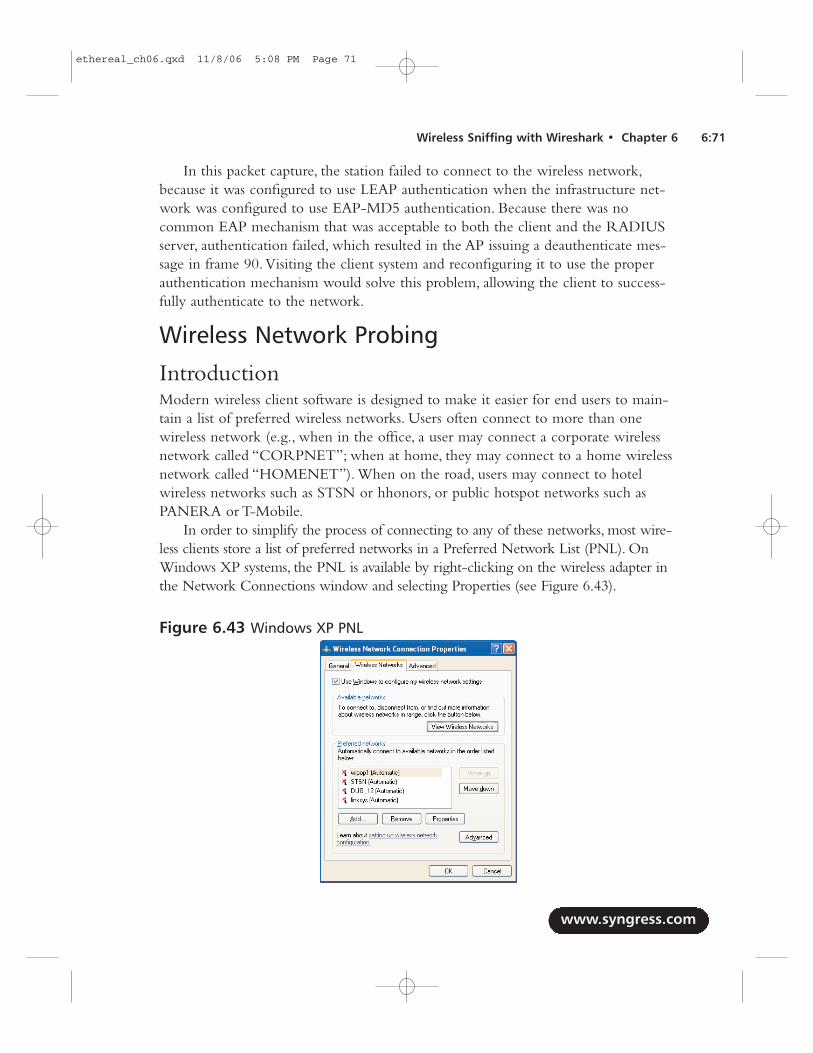
In this packet capture, the station failed to connect to the wireless network,because it was configured to use LEAP authentication when the infrastructure net-work was configured to use EAP-MD5 authentication. Because there was nocommon EAP mechanism that was acceptable to both the client and the RADIUSserver, authentication failed, which resulted in the AP issuing a deauthenticate mes-sage in frame 90. Visiting the client system and reconfiguring it to use the properauthentication mechanism would solve this problem, allowing the client to success-fully authenticate to the network.
Wireless Network Probing
IntroductionModern wireless client software is designed to make it easier for end users to main-tain a list of preferred wireless networks. Users often connect to more than onewireless network (e.g., when in the office, a user may connect a corporate wirelessnetwork called “CORPNET”; when at home, they may connect to a home wirelessnetwork called “HOMENET”). When on the road, users may connect to hotelwireless networks such as STSN or hhonors, or public hotspot networks such asPANERA or T-Mobile.
In order to simplify the process of connecting to any of these networks, most wire-less clients store a list of preferred networks in a Preferred Network List (PNL). OnWindows XP systems, the PNL is available by right-clicking on the wireless adapter inthe Network Connections window and selecting Properties (see Figure 6.43).
www.syngress.com
Wireless Sniffing with Wireshark • Chapter 6 6:71
Figure 6.43 Windows XP PNL
ethereal_ch06.qxd 11/8/06 5:08 PM Page 71
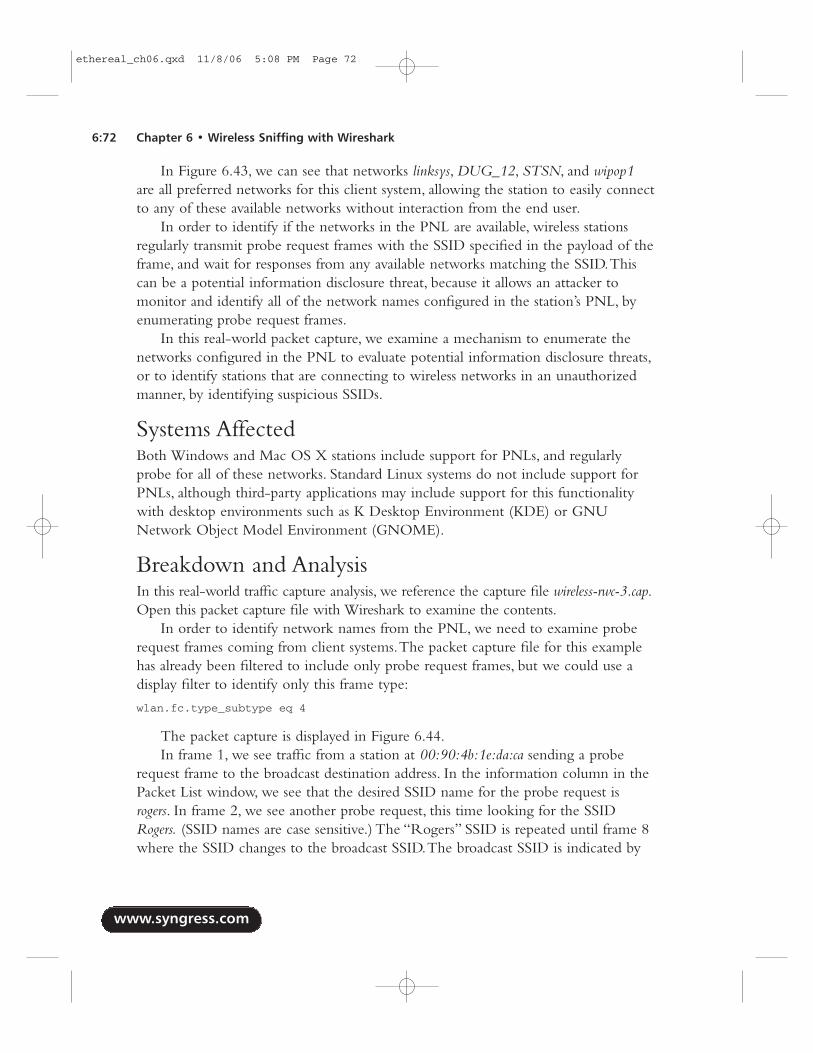
In Figure 6.43, we can see that networks linksys, DUG_12, STSN, and wipop1are all preferred networks for this client system, allowing the station to easily connectto any of these available networks without interaction from the end user.
In order to identify if the networks in the PNL are available, wireless stationsregularly transmit probe request frames with the SSID specified in the payload of theframe, and wait for responses from any available networks matching the SSID.Thiscan be a potential information disclosure threat, because it allows an attacker tomonitor and identify all of the network names configured in the station’s PNL, byenumerating probe request frames.
In this real-world packet capture, we examine a mechanism to enumerate thenetworks configured in the PNL to evaluate potential information disclosure threats,or to identify stations that are connecting to wireless networks in an unauthorizedmanner, by identifying suspicious SSIDs.
Systems AffectedBoth Windows and Mac OS X stations include support for PNLs, and regularlyprobe for all of these networks. Standard Linux systems do not include support forPNLs, although third-party applications may include support for this functionalitywith desktop environments such as K Desktop Environment (KDE) or GNUNetwork Object Model Environment (GNOME).
Breakdown and AnalysisIn this real-world traffic capture analysis, we reference the capture file wireless-rwc-3.cap.Open this packet capture file with Wireshark to examine the contents.
In order to identify network names from the PNL, we need to examine proberequest frames coming from client systems.The packet capture file for this examplehas already been filtered to include only probe request frames, but we could use adisplay filter to identify only this frame type:
wlan.fc.type_subtype eq 4
The packet capture is displayed in Figure 6.44.In frame 1, we see traffic from a station at 00:90:4b:1e:da:ca sending a probe
request frame to the broadcast destination address. In the information column in thePacket List window, we see that the desired SSID name for the probe request isrogers. In frame 2, we see another probe request, this time looking for the SSIDRogers. (SSID names are case sensitive.) The “Rogers” SSID is repeated until frame 8where the SSID changes to the broadcast SSID.The broadcast SSID is indicated by
www.syngress.com
6:72 Chapter 6 • Wireless Sniffing with Wireshark
ethereal_ch06.qxd 11/8/06 5:08 PM Page 72
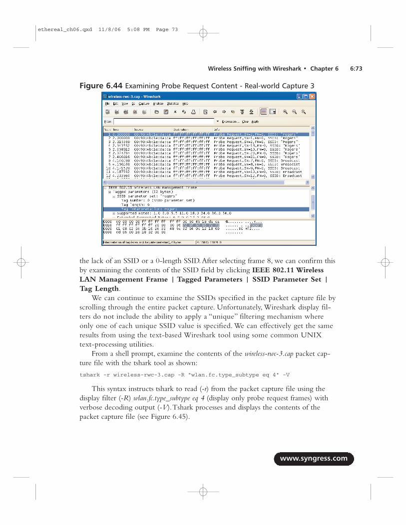
the lack of an SSID or a 0-length SSID.After selecting frame 8, we can confirm thisby examining the contents of the SSID field by clicking IEEE 802.11 WirelessLAN Management Frame | Tagged Parameters | SSID Parameter Set |Tag Length.
We can continue to examine the SSIDs specified in the packet capture file byscrolling through the entire packet capture. Unfortunately, Wireshark display fil-ters do not include the ability to apply a “unique” filtering mechanism whereonly one of each unique SSID value is specified. We can effectively get the sameresults from using the text-based Wireshark tool using some common UNIXtext-processing utilities.
From a shell prompt, examine the contents of the wireless-rwc-3.cap packet cap-ture file with the tshark tool as shown:
tshark -r wireless-rwc-3.cap -R "wlan.fc.type_subtype eq 4" -V
This syntax instructs tshark to read (-r) from the packet capture file using thedisplay filter (-R) wlan.fc.type_subtype eq 4 (display only probe request frames) withverbose decoding output (-V).Tshark processes and displays the contents of thepacket capture file (see Figure 6.45).
www.syngress.com
Wireless Sniffing with Wireshark • Chapter 6 6:73
Figure 6.44 Examining Probe Request Content - Real-world Capture 3
ethereal_ch06.qxd 11/8/06 5:08 PM Page 73
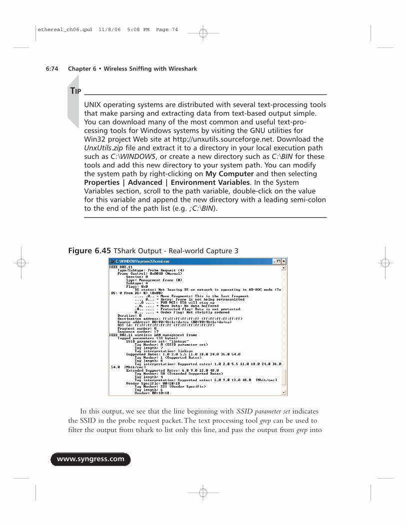
TIP
UNIX operating systems are distributed with several text-processing toolsthat make parsing and extracting data from text-based output simple.You can download many of the most common and useful text-pro-cessing tools for Windows systems by visiting the GNU utilities forWin32 project Web site at http://unxutils.sourceforge.net. Download theUnxUtils.zip file and extract it to a directory in your local execution pathsuch as C:\WINDOWS, or create a new directory such as C:\BIN for thesetools and add this new directory to your system path. You can modifythe system path by right-clicking on My Computer and then selectingProperties | Advanced | Environment Variables. In the SystemVariables section, scroll to the path variable, double-click on the valuefor this variable and append the new directory with a leading semi-colonto the end of the path list (e.g. ;C:\BIN).
In this output, we see that the line beginning with SSID parameter set indicatesthe SSID in the probe request packet.The text processing tool grep can be used tofilter the output from tshark to list only this line, and pass the output from grep into
www.syngress.com
6:74 Chapter 6 • Wireless Sniffing with Wireshark
Figure 6.45 TShark Output - Real-world Capture 3
ethereal_ch06.qxd 11/8/06 5:08 PM Page 74
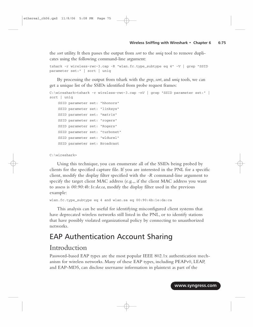
the sort utility. It then passes the output from sort to the uniq tool to remove dupli-cates using the following command-line argument:
tshark -r wireless-rwc-3.cap -R "wlan.fc.type_subtype eq 4" -V | grep "SSIDparameter set:" | sort | uniq
By processing the output from tshark with the grep, sort, and uniq tools, we canget a unique list of the SSIDs identified from probe request frames:
C:\wireshark>tshark -r wireless-rwc-3.cap -nV | grep "SSID parameter set:" |sort | uniq
SSID parameter set: "hhonors"
SSID parameter set: "linksys"
SSID parameter set: "matrix"
SSID parameter set: "rogers"
SSID parameter set: "Rogers"
SSID parameter set: "turbonet"
SSID parameter set: "wldurel"
SSID parameter set: Broadcast
C:\wireshark>
Using this technique, you can enumerate all of the SSIDs being probed byclients for the specified capture file. If you are interested in the PNL for a specificclient, modify the display filter specified with the -R command-line argument tospecify the target client MAC address (e.g.,, if the client MAC address you wantto assess is 00:90:4b:1e:da:ca, modify the display filter used in the previousexample:
wlan.fc.type_subtype eq 4 and wlan.sa eq 00:90:4b:1e:da:ca
This analysis can be useful for identifying misconfigured client systems thathave deprecated wireless networks still listed in the PNL, or to identify stationsthat have possibly violated organizational policy by connecting to unauthorizednetworks.
EAP Authentication Account SharingIntroductionPassword-based EAP types are the most popular IEEE 802.1x authentication mech-anism for wireless networks. Many of these EAP types, including PEAPv0, LEAP,and EAP-MD5, can disclose username information in plaintext as part of the
www.syngress.com
Wireless Sniffing with Wireshark • Chapter 6 6:75
ethereal_ch06.qxd 11/8/06 5:08 PM Page 75
authentication exchange.This can be potentially advantageous to an attacker, but isalso advantageous to an administrator to assess the identities of users on the wirelessnetwork.
Systems AffectedThis analysis applies to wireless networks using IEEE 802.1x authentication forwireless networks, with an EAP type that discloses username information in plain-text as part of the authentication exchange. Examples of EAP types that disclose thisinformation include EAP-MD5, LEAP, and PEAPv0.
Breakdown and AnalysisIn this real-world traffic capture analysis, we reference the capture file wireless-rwc-4.cap. Open this packet capture file with Wireshark to examine the contents.
NOTE
It was necessary to sanitize the wireless-rwc-4.cap contents before beingallowed to include it as a reference for this book. Please disregard thetimestamp information for each frame, as it is not valid for this analysis.Other sources of information in the capture have also been modifiedthat do not affect the outcome of the analysis.
In order to examine username information disclosed in plaintext, we are pri-marily concerned with EAP traffic.Apply the following display filter to examine allEAP traffic in the capture file:
eap
The initial display after applying the filter for this packet capture is displayed inFigure 6.46.
Looking at the information column, we can see that this is a capture of CiscoLEAP (EAP-Cisco) traffic. While the first two frames in the display filter resultsdon’t disclose username information, selecting frame 12 (the third frame of the dis-play filter results) displays the string nthom in the Packet Bytes window. Clicking802.1X Authentication | Extensible Authentication Protocol | Identityconfirms that this is the username of the person at this workstation who is authenti-cating to the wireless network.
www.syngress.com
6:76 Chapter 6 • Wireless Sniffing with Wireshark
ethereal_ch06.qxd 11/8/06 5:08 PM Page 76
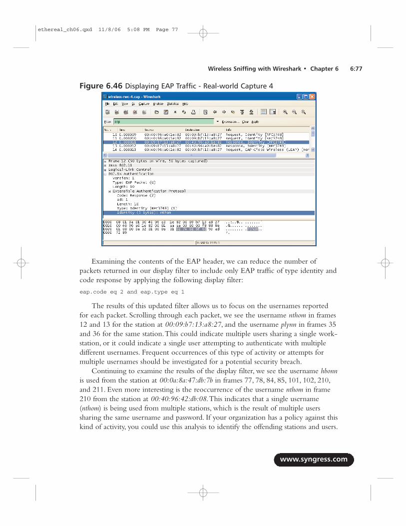
Examining the contents of the EAP header, we can reduce the number ofpackets returned in our display filter to include only EAP traffic of type identity andcode response by applying the following display filter:
eap.code eq 2 and eap.type eq 1
The results of this updated filter allows us to focus on the usernames reportedfor each packet. Scrolling through each packet, we see the username nthom in frames12 and 13 for the station at 00:09:b7:13:a8:27, and the username plynn in frames 35and 36 for the same station.This could indicate multiple users sharing a single work-station, or it could indicate a single user attempting to authenticate with multipledifferent usernames. Frequent occurrences of this type of activity or attempts formultiple usernames should be investigated for a potential security breach.
Continuing to examine the results of the display filter, we see the username hbonnis used from the station at 00:0a:8a:47:db:7b in frames 77, 78, 84, 85, 101, 102, 210,and 211. Even more interesting is the reoccurrence of the username nthom in frame210 from the station at 00:40:96:42:db:08.This indicates that a single username(nthom) is being used from multiple stations, which is the result of multiple userssharing the same username and password. If your organization has a policy against thiskind of activity, you could use this analysis to identify the offending stations and users.
www.syngress.com
Wireless Sniffing with Wireshark • Chapter 6 6:77
Figure 6.46 Displaying EAP Traffic - Real-world Capture 4
ethereal_ch06.qxd 11/8/06 5:08 PM Page 77
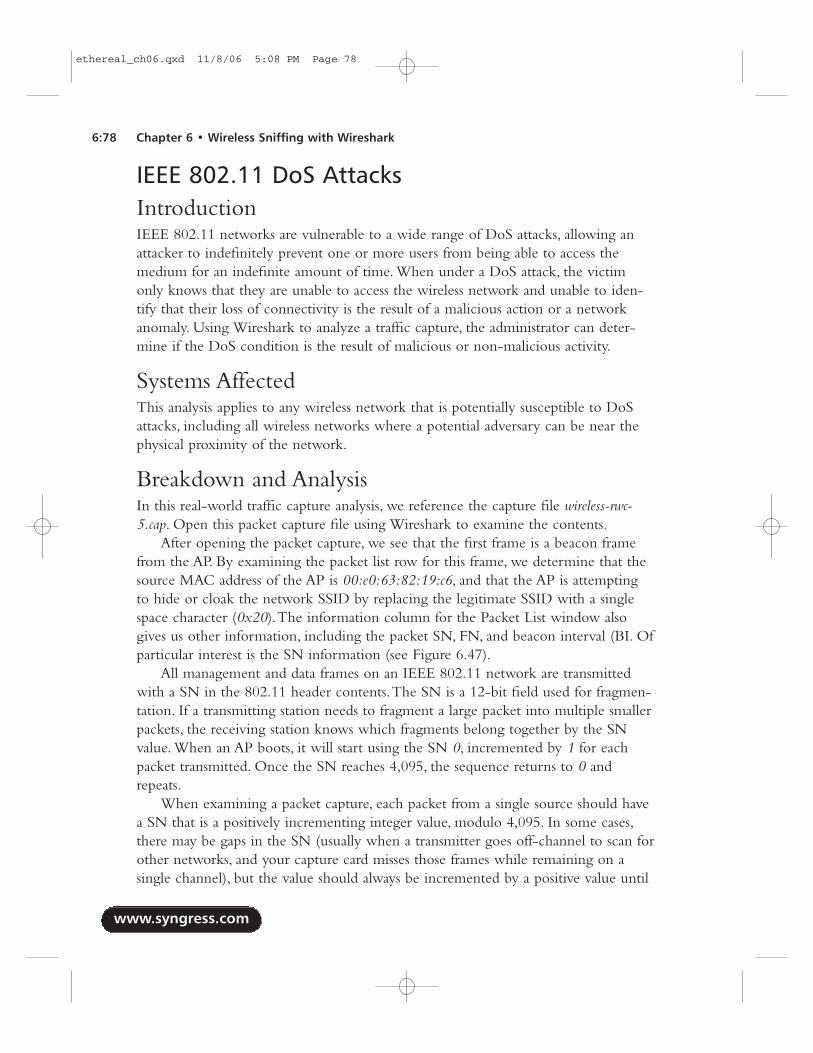
IEEE 802.11 DoS AttacksIntroductionIEEE 802.11 networks are vulnerable to a wide range of DoS attacks, allowing anattacker to indefinitely prevent one or more users from being able to access themedium for an indefinite amount of time. When under a DoS attack, the victimonly knows that they are unable to access the wireless network and unable to iden-tify that their loss of connectivity is the result of a malicious action or a networkanomaly. Using Wireshark to analyze a traffic capture, the administrator can deter-mine if the DoS condition is the result of malicious or non-malicious activity.
Systems AffectedThis analysis applies to any wireless network that is potentially susceptible to DoSattacks, including all wireless networks where a potential adversary can be near thephysical proximity of the network.
Breakdown and AnalysisIn this real-world traffic capture analysis, we reference the capture file wireless-rwc-5.cap. Open this packet capture file using Wireshark to examine the contents.
After opening the packet capture, we see that the first frame is a beacon framefrom the AP. By examining the packet list row for this frame, we determine that thesource MAC address of the AP is 00:e0:63:82:19:c6, and that the AP is attemptingto hide or cloak the network SSID by replacing the legitimate SSID with a singlespace character (0x20).The information column for the Packet List window alsogives us other information, including the packet SN, FN, and beacon interval (BI. Ofparticular interest is the SN information (see Figure 6.47).
All management and data frames on an IEEE 802.11 network are transmittedwith a SN in the 802.11 header contents.The SN is a 12-bit field used for fragmen-tation. If a transmitting station needs to fragment a large packet into multiple smallerpackets, the receiving station knows which fragments belong together by the SNvalue. When an AP boots, it will start using the SN 0, incremented by 1 for eachpacket transmitted. Once the SN reaches 4,095, the sequence returns to 0 andrepeats.
When examining a packet capture, each packet from a single source should havea SN that is a positively incrementing integer value, modulo 4,095. In some cases,there may be gaps in the SN (usually when a transmitter goes off-channel to scan forother networks, and your capture card misses those frames while remaining on asingle channel), but the value should always be incremented by a positive value until
www.syngress.com
6:78 Chapter 6 • Wireless Sniffing with Wireshark
ethereal_ch06.qxd 11/8/06 5:08 PM Page 78
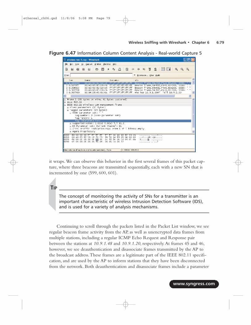
it wraps. We can observe this behavior in the first several frames of this packet cap-ture, where three beacons are transmitted sequentially, each with a new SN that isincremented by one (599, 600, 601).
TIP
The concept of monitoring the activity of SNs for a transmitter is animportant characteristic of wireless Intrusion Detection Software (IDS),and is used for a variety of analysis mechanisms.
Continuing to scroll through the packets listed in the Packet List window, we seeregular beacon frame activity from the AP, as well as unencrypted data frames frommultiple stations, including a regular ICMP Echo Request and Response pairbetween the stations at 10.9.1.48 and 10.9.1.20, respectively.At frames 45 and 46,however, we see deauthentication and disassociate frames transmitted by the AP tothe broadcast address.These frames are a legitimate part of the IEEE 802.11 specifi-cation, and are used by the AP to inform stations that they have been disconnectedfrom the network. Both deauthentication and disassociate frames include a parameter
www.syngress.com
Wireless Sniffing with Wireshark • Chapter 6 6:79
Figure 6.47 Information Column Content Analysis - Real-world Capture 5
ethereal_ch06.qxd 11/8/06 5:08 PM Page 79
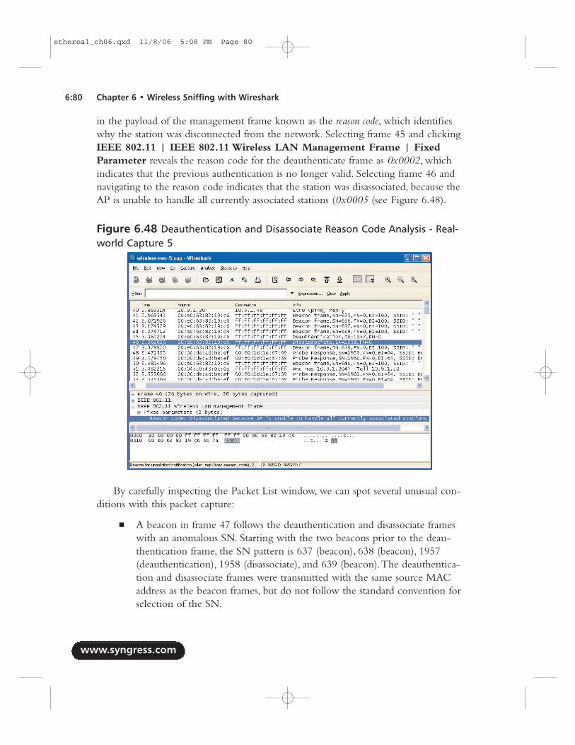
in the payload of the management frame known as the reason code, which identifieswhy the station was disconnected from the network. Selecting frame 45 and clickingIEEE 802.11 | IEEE 802.11 Wireless LAN Management Frame | FixedParameter reveals the reason code for the deauthenticate frame as 0x0002, whichindicates that the previous authentication is no longer valid. Selecting frame 46 andnavigating to the reason code indicates that the station was disassociated, because theAP is unable to handle all currently associated stations (0x0005 (see Figure 6.48).
By carefully inspecting the Packet List window, we can spot several unusual con-ditions with this packet capture:
■ A beacon in frame 47 follows the deauthentication and disassociate frameswith an anomalous SN. Starting with the two beacons prior to the deau-thentication frame, the SN pattern is 637 (beacon), 638 (beacon), 1957(deauthentication), 1958 (disassociate), and 639 (beacon).The deauthentica-tion and disassociate frames were transmitted with the same source MACaddress as the beacon frames, but do not follow the standard convention forselection of the SN.
www.syngress.com
6:80 Chapter 6 • Wireless Sniffing with Wireshark
Figure 6.48 Deauthentication and Disassociate Reason Code Analysis - Real-world Capture 5
ethereal_ch06.qxd 11/8/06 5:08 PM Page 80
■ Following frame 47, we have two probe response frames with SNs thatfollow the previous deauthentication and disassociate frames, but conflictwith the beacon frame.This is unusual from a SN perspective, because weare observing probe responses without a prior probe request frame.However, it is possible that our sniffer dropped the probe request frame,which must be taken into consideration.
■ The source MAC address of the probe response frames is 00:00:de:ad:be:ef.While this is a valid MAC address, it is not the original MAC addressassigned to the station that transmitted this packet.
■ The SSID contents of the probe response frame are sent to the broadcastSSID (a 0-length SSID indicates the broadcast SSID).This is also unusual,because the AP must include an SSID in the probe response frame, even ifit is the cloaked SSID. (In this network, the cloaked SSID is representedwith a single space character.)
These factors all point to the notion that the deauthentication and disassociateframes were spoofed and not transmitted by the legitimate source, and that the proberesponse frames were sent in an effort to otherwise manipulate the network to theattacker’s goals.
Examining the contents of the packet capture further, we see more similar deau-thentication and disassociate activity with anomalous SN values, as well as additionalunsolicited probe responses with the unusual source MAC address. With this analysis,we can determine that any DoS conditions users are experiencing are the effect ofan attack against the network, not from the result of misconfigured clients or otherlegitimate network anomalies.
NOTE
The technique used in this packet capture is known as the NULL SSIDDoS attack, where an attacker is attempting to get client stations to pro-cess malformed probe response frames in an effort to manipulatefirmware on legacy wireless LAN cards. This is particularly effective as aDoS attack, because it renders the victim wireless card inoperable untilthe card has been power-cycled. More information on this bug is avail-able in the Wireless Vulnerabilities and Exploits database as WVE-2006-0064 (www.wve.org/entries/show/WVE-2006-0064).
www.syngress.com
Wireless Sniffing with Wireshark • Chapter 6 6:81
ethereal_ch06.qxd 11/8/06 5:08 PM Page 81
IEEE 802.11 Spoofing AttacksIntroductionA significant security weakness in IEEE 802.11 networks is the lack of a crypto-graphically secure integrity check mechanism for traffic on the wireless network.While more modern encryption protocols such as TKIP or CCMP provide asecure integrity check over the payload of a data frame, it does not prevent at leastpartial analysis of a frame transmitted by an attacker with a spoofed source MACaddress.This weakness exposes a wireless network to several classes of attacks,including packet spoofing attacks where an attacker impersonates a legitimate sta-tion on the network.
Systems AffectedThis analysis focuses on a vulnerability in a WEP network, but the principles ofanalysis for identifying spoofed traffic, apply to all IEEE 802.11 wireless networks.
Breakdown and AnalysisIn this real-world traffic capture analysis, we reference the capture file wireless-rwc-6.cap. Open this packet capture file with Wireshark to examine the contents.
Upon opening the packet capture, we see traffic from multiple stations andbeacon frames for the WEPNET SSID.After examining the first few frames, youmay notice an anomalous SN combination for the station at 00:13:ce:55:98:ef inframes 4 (SN=2651), 8 (SN=2652), and 10 (SN=591). However, when assessing thecontents of frames, it is important to examine the status of the From DS and To DSflags to determine if the frame is coming from a station on the wireless network, orif it is being retransmitted by an AP to other stations on the network. Select frame 8and click IEEE 802.11 | Frame Control | Flags to examine the DS status infor-mation (see Figure 6.49).
Examining the DS status line, we see that the frame is being transmitted to thedistribution system (To DS).This indicates that frame 8 is being transmitted by awireless station to the AP. Selecting frame 10 and navigating to the DS status lineindicates that the frame is being transmitted from the distribution system (From DS)by the AP.This is not indicative of a spoofing attack; rather, the AP is retransmittingthe frame from the station to be received by other stations on the AP.
In order to inspect the SN patterns for signs of possible spoofing activity, we canapply a display filter to examine only traffic sent to the DS from wireless stations:
wlan.fc.tods eq 1 and wlan.fc.fromds eq 0
www.syngress.com
6:82 Chapter 6 • Wireless Sniffing with Wireshark
ethereal_ch06.qxd 11/8/06 5:08 PM Page 82
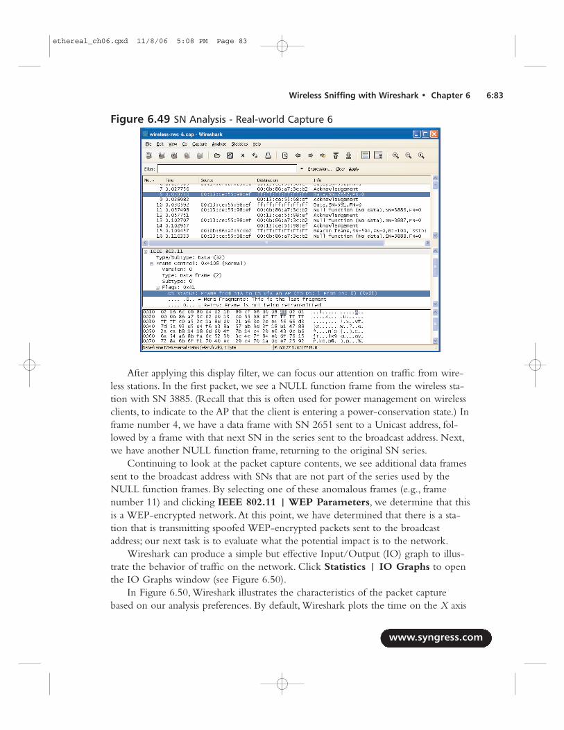
After applying this display filter, we can focus our attention on traffic from wire-less stations. In the first packet, we see a NULL function frame from the wireless sta-tion with SN 3885. (Recall that this is often used for power management on wirelessclients, to indicate to the AP that the client is entering a power-conservation state.) Inframe number 4, we have a data frame with SN 2651 sent to a Unicast address, fol-lowed by a frame with that next SN in the series sent to the broadcast address. Next,we have another NULL function frame, returning to the original SN series.
Continuing to look at the packet capture contents, we see additional data framessent to the broadcast address with SNs that are not part of the series used by theNULL function frames. By selecting one of these anomalous frames (e.g., framenumber 11) and clicking IEEE 802.11 | WEP Parameters, we determine that thisis a WEP-encrypted network.At this point, we have determined that there is a sta-tion that is transmitting spoofed WEP-encrypted packets sent to the broadcastaddress; our next task is to evaluate what the potential impact is to the network.
Wireshark can produce a simple but effective Input/Output (IO) graph to illus-trate the behavior of traffic on the network. Click Statistics | IO Graphs to openthe IO Graphs window (see Figure 6.50).
In Figure 6.50, Wireshark illustrates the characteristics of the packet capturebased on our analysis preferences. By default, Wireshark plots the time on the X axis
www.syngress.com
Wireless Sniffing with Wireshark • Chapter 6 6:83
Figure 6.49 SN Analysis - Real-world Capture 6
ethereal_ch06.qxd 11/8/06 5:08 PM Page 83
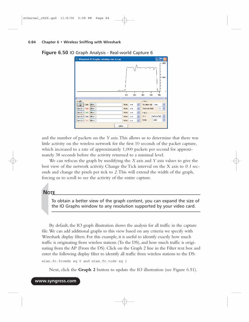
and the number of packets on the Y axis.This allows us to determine that there waslittle activity on the wireless network for the first 10 seconds of the packet capture,which increased to a rate of approximately 1,000 packets per second for approxi-mately 38 seconds before the activity returned to a minimal level.
We can refocus the graph by modifying the X axis and Y axis values to give thebest view of the network activity. Change the Tick interval on the X axis to 0.1 sec-onds and change the pixels per tick to 2.This will extend the width of the graph,forcing us to scroll to see the activity of the entire capture.
NOTE
To obtain a better view of the graph content, you can expand the size ofthe IO Graphs window to any resolution supported by your video card.
By default, the IO graph illustration shows the analysis for all traffic in the capturefile.We can add additional graphs to this view based on any criteria we specify withWireshark display filters. For this example, it is useful to identify exactly how muchtraffic is originating from wireless stations (To the DS), and how much traffic is origi-nating from the AP (From the DS). Click on the Graph 2 line in the Filter text box andenter the following display filter to identify all traffic from wireless stations to the DS:
wlan.fc.fromds eq 0 and wlan.fc.tods eq 1
Next, click the Graph 2 button to update the IO illustration (see Figure 6.51).
www.syngress.com
6:84 Chapter 6 • Wireless Sniffing with Wireshark
Figure 6.50 IO Graph Analysis - Real-world Capture 6
ethereal_ch06.qxd 11/8/06 5:08 PM Page 84
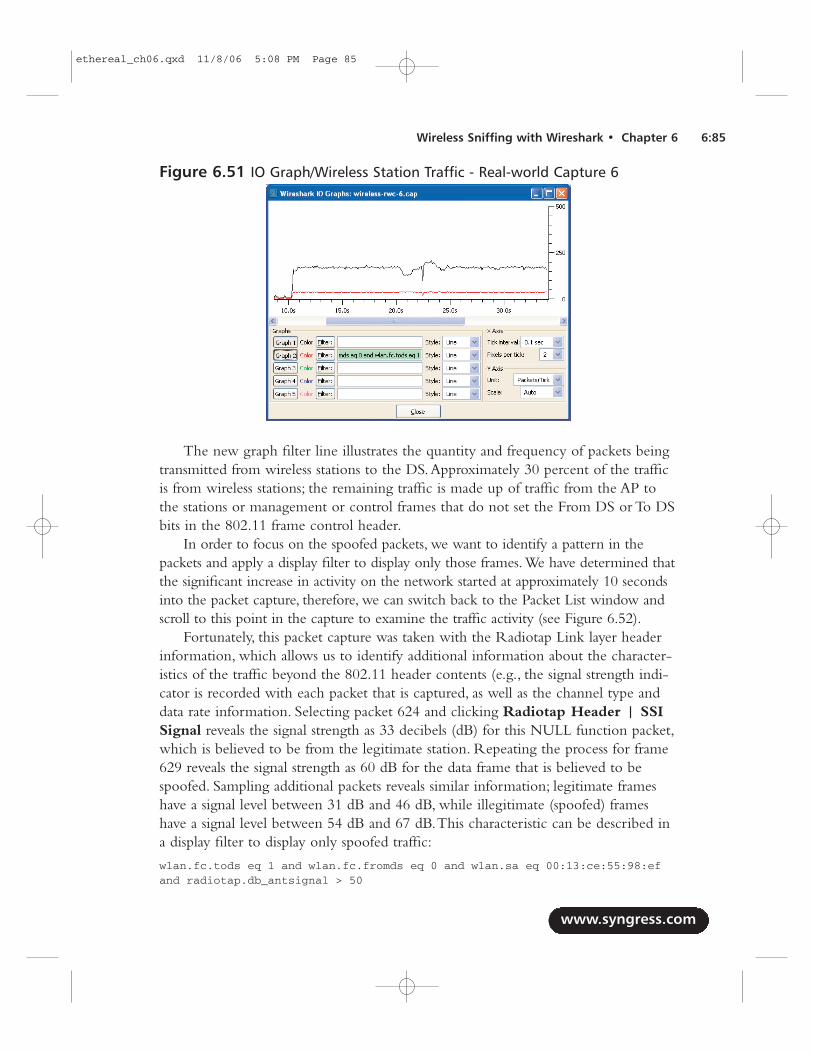
The new graph filter line illustrates the quantity and frequency of packets beingtransmitted from wireless stations to the DS.Approximately 30 percent of the trafficis from wireless stations; the remaining traffic is made up of traffic from the AP tothe stations or management or control frames that do not set the From DS or To DSbits in the 802.11 frame control header.
In order to focus on the spoofed packets, we want to identify a pattern in thepackets and apply a display filter to display only those frames.We have determined thatthe significant increase in activity on the network started at approximately 10 secondsinto the packet capture, therefore, we can switch back to the Packet List window andscroll to this point in the capture to examine the traffic activity (see Figure 6.52).
Fortunately, this packet capture was taken with the Radiotap Link layer headerinformation, which allows us to identify additional information about the character-istics of the traffic beyond the 802.11 header contents (e.g., the signal strength indi-cator is recorded with each packet that is captured, as well as the channel type anddata rate information. Selecting packet 624 and clicking Radiotap Header | SSISignal reveals the signal strength as 33 decibels (dB) for this NULL function packet,which is believed to be from the legitimate station. Repeating the process for frame629 reveals the signal strength as 60 dB for the data frame that is believed to bespoofed. Sampling additional packets reveals similar information; legitimate frameshave a signal level between 31 dB and 46 dB, while illegitimate (spoofed) frameshave a signal level between 54 dB and 67 dB.This characteristic can be described ina display filter to display only spoofed traffic:
wlan.fc.tods eq 1 and wlan.fc.fromds eq 0 and wlan.sa eq 00:13:ce:55:98:efand radiotap.db_antsignal > 50
www.syngress.com
Wireless Sniffing with Wireshark • Chapter 6 6:85
Figure 6.51 IO Graph/Wireless Station Traffic - Real-world Capture 6
ethereal_ch06.qxd 11/8/06 5:08 PM Page 85
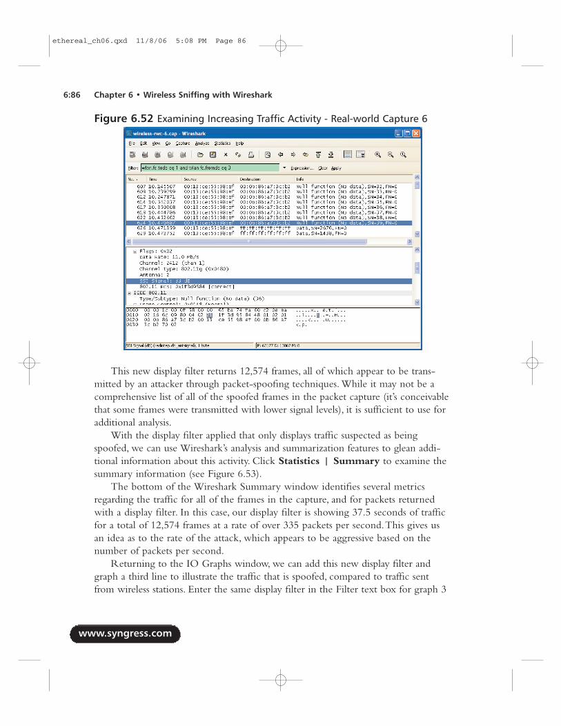
This new display filter returns 12,574 frames, all of which appear to be trans-mitted by an attacker through packet-spoofing techniques. While it may not be acomprehensive list of all of the spoofed frames in the packet capture (it’s conceivablethat some frames were transmitted with lower signal levels), it is sufficient to use foradditional analysis.
With the display filter applied that only displays traffic suspected as beingspoofed, we can use Wireshark’s analysis and summarization features to glean addi-tional information about this activity. Click Statistics | Summary to examine thesummary information (see Figure 6.53).
The bottom of the Wireshark Summary window identifies several metricsregarding the traffic for all of the frames in the capture, and for packets returnedwith a display filter. In this case, our display filter is showing 37.5 seconds of trafficfor a total of 12,574 frames at a rate of over 335 packets per second.This gives usan idea as to the rate of the attack, which appears to be aggressive based on thenumber of packets per second.
Returning to the IO Graphs window, we can add this new display filter andgraph a third line to illustrate the traffic that is spoofed, compared to traffic sentfrom wireless stations. Enter the same display filter in the Filter text box for graph 3
www.syngress.com
6:86 Chapter 6 • Wireless Sniffing with Wireshark
Figure 6.52 Examining Increasing Traffic Activity - Real-world Capture 6
ethereal_ch06.qxd 11/8/06 5:08 PM Page 86
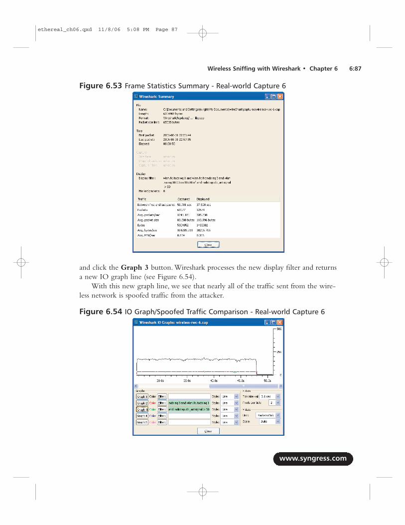
and click the Graph 3 button. Wireshark processes the new display filter and returnsa new IO graph line (see Figure 6.54).
With this new graph line, we see that nearly all of the traffic sent from the wire-less network is spoofed traffic from the attacker.
www.syngress.com
Wireless Sniffing with Wireshark • Chapter 6 6:87
Figure 6.53 Frame Statistics Summary - Real-world Capture 6
Figure 6.54 IO Graph/Spoofed Traffic Comparison - Real-world Capture 6
ethereal_ch06.qxd 11/8/06 5:08 PM Page 87
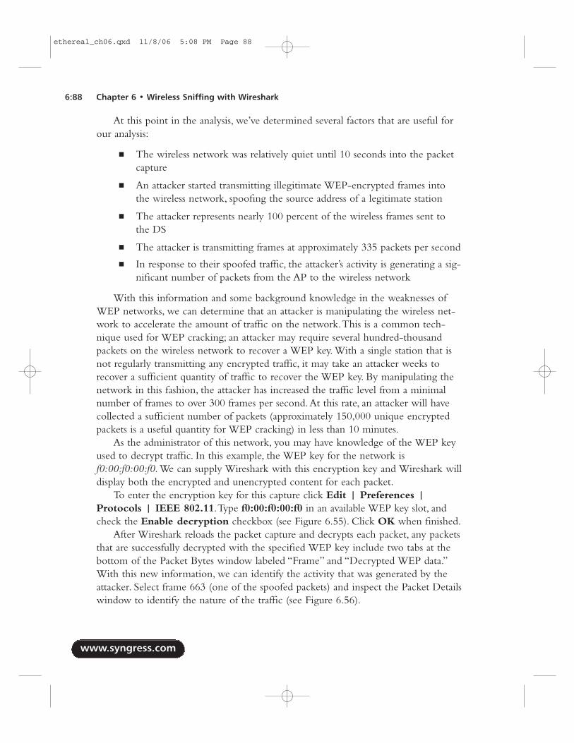
At this point in the analysis, we’ve determined several factors that are useful forour analysis:
■ The wireless network was relatively quiet until 10 seconds into the packetcapture
■ An attacker started transmitting illegitimate WEP-encrypted frames intothe wireless network, spoofing the source address of a legitimate station
■ The attacker represents nearly 100 percent of the wireless frames sent tothe DS
■ The attacker is transmitting frames at approximately 335 packets per second
■ In response to their spoofed traffic, the attacker’s activity is generating a sig-nificant number of packets from the AP to the wireless network
With this information and some background knowledge in the weaknesses ofWEP networks, we can determine that an attacker is manipulating the wireless net-work to accelerate the amount of traffic on the network.This is a common tech-nique used for WEP cracking; an attacker may require several hundred-thousandpackets on the wireless network to recover a WEP key. With a single station that isnot regularly transmitting any encrypted traffic, it may take an attacker weeks torecover a sufficient quantity of traffic to recover the WEP key. By manipulating thenetwork in this fashion, the attacker has increased the traffic level from a minimalnumber of frames to over 300 frames per second.At this rate, an attacker will havecollected a sufficient number of packets (approximately 150,000 unique encryptedpackets is a useful quantity for WEP cracking) in less than 10 minutes.
As the administrator of this network, you may have knowledge of the WEP keyused to decrypt traffic. In this example, the WEP key for the network isf0:00:f0:00:f0. We can supply Wireshark with this encryption key and Wireshark willdisplay both the encrypted and unencrypted content for each packet.
To enter the encryption key for this capture click Edit | Preferences |Protocols | IEEE 802.11.Type f0:00:f0:00:f0 in an available WEP key slot, andcheck the Enable decryption checkbox (see Figure 6.55). Click OK when finished.
After Wireshark reloads the packet capture and decrypts each packet, any packetsthat are successfully decrypted with the specified WEP key include two tabs at thebottom of the Packet Bytes window labeled “Frame” and “Decrypted WEP data.”With this new information, we can identify the activity that was generated by theattacker. Select frame 663 (one of the spoofed packets) and inspect the Packet Detailswindow to identify the nature of the traffic (see Figure 6.56).
www.syngress.com
6:88 Chapter 6 • Wireless Sniffing with Wireshark
ethereal_ch06.qxd 11/8/06 5:08 PM Page 88
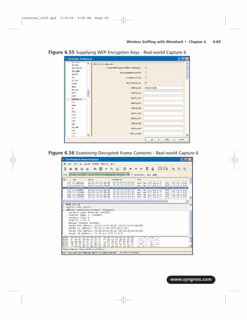
www.syngress.com
Wireless Sniffing with Wireshark • Chapter 6 6:89
Figure 6.55 Supplying WEP Encryption Keys - Real-world Capture 6
Figure 6.56 Examining Decrypted Frame Contents - Real-world Capture 6
ethereal_ch06.qxd 11/8/06 5:08 PM Page 89
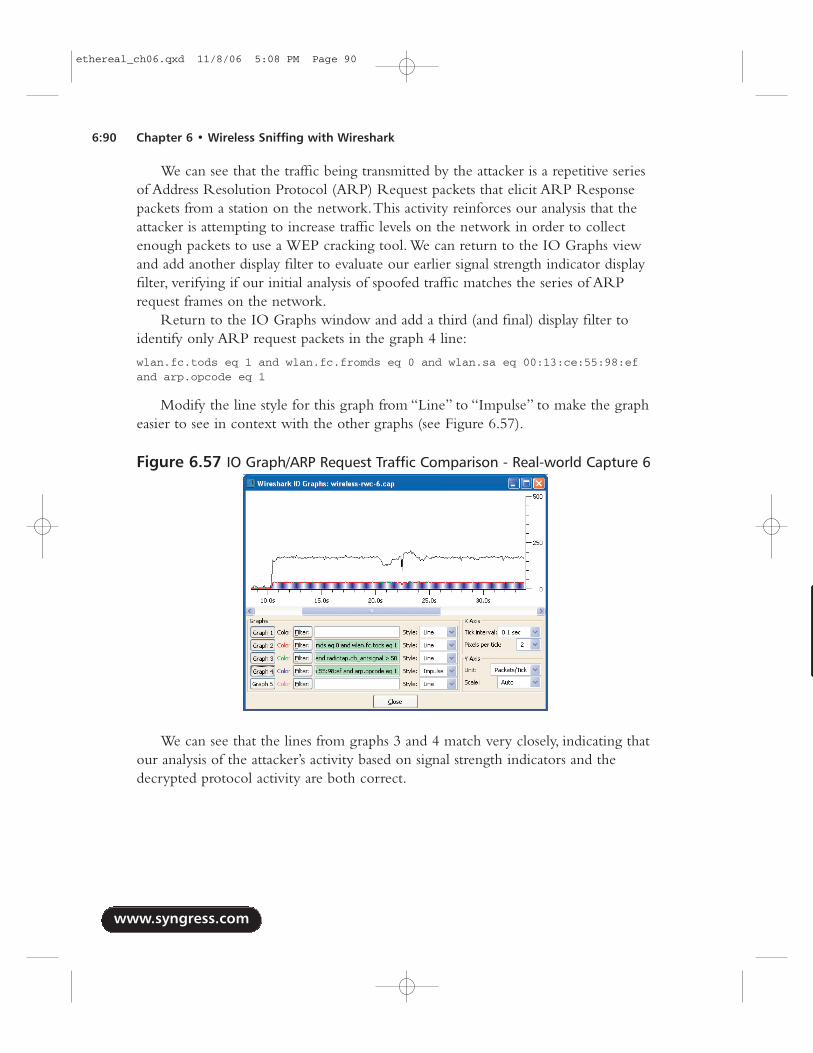
We can see that the traffic being transmitted by the attacker is a repetitive seriesof Address Resolution Protocol (ARP) Request packets that elicit ARP Responsepackets from a station on the network.This activity reinforces our analysis that theattacker is attempting to increase traffic levels on the network in order to collectenough packets to use a WEP cracking tool. We can return to the IO Graphs viewand add another display filter to evaluate our earlier signal strength indicator displayfilter, verifying if our initial analysis of spoofed traffic matches the series of ARPrequest frames on the network.
Return to the IO Graphs window and add a third (and final) display filter toidentify only ARP request packets in the graph 4 line:
wlan.fc.tods eq 1 and wlan.fc.fromds eq 0 and wlan.sa eq 00:13:ce:55:98:efand arp.opcode eq 1
Modify the line style for this graph from “Line” to “Impulse” to make the grapheasier to see in context with the other graphs (see Figure 6.57).
We can see that the lines from graphs 3 and 4 match very closely, indicating thatour analysis of the attacker’s activity based on signal strength indicators and thedecrypted protocol activity are both correct.
www.syngress.com
6:90 Chapter 6 • Wireless Sniffing with Wireshark
Figure 6.57 IO Graph/ARP Request Traffic Comparison - Real-world Capture 6
ethereal_ch06.qxd 11/8/06 5:08 PM Page 90
NOTE
This attack activity matches the mechanism implemented in the Aireplaytool that ships with the Aircrack-ng suite of WEP and WPA-PSK crackingtools. This attack tool is assigned the identifier WVE-2005-0015 by theWireless Vulnerabilities and Exploits group; visitwww.wve.org/entries/show/WVE-2005-0015 for additional informationabout this attack tool.
Malformed Traffic AnalysisIntroductionA recent development in the saga of wireless LAN security is the use of IEEE802.11 protocol fuzzing against wireless stations to identify bugs in driver software.Fuzzing is a technique where an attacker sends malformed packets that violate thespecification of a protocol to a client or a server. If the server or client software isnot written to expect invalid packets, it can sometimes trigger flaws in software thatcan be exploited by an attacker.
www.syngress.com
Wireless Sniffing with Wireshark • Chapter 6 6:91
IEEE 802.11 Protocol FuzzingA recent advancement in the list of techniques that can be used to compromisethe security of a wireless network, is the use of IEEE 802.11 protocol fuzzing.Fuzzing is a technique used by security researchers and attackers to identifysoftware weaknesses when presented with unexpected data. This technique isfrequently used to identify potential security flaws in software that can be suc-cessfully exploited to the attacker’s gain. Once an attacker identifies a sequenceof data that causes a victim to behave in a way the target software’s author didnot intend, the technique is developed into an exploit that can be used repeat-edly against vulnerable stations. In the case of IEEE 802.11 wireless LANs,fuzzing is being used to identify weaknesses in device driver software whenpresented with malformed or unexpected wireless frames. These frames can bemalformed by violating the framing rules stated in the 802.11 specification orby violating the expected order and timing of otherwise legitimate packets.
Notes from the Underground…
Continued
ethereal_ch06.qxd 11/8/06 5:08 PM Page 91
Systems AffectedThis analysis applies to all wireless LANs where an attacker can get within physicalrange of the wireless network.
Breakdown and AnalysisCapture 1In this real-world traffic capture analysis, we reference the capture file wireless-rwc-7.cap. Open this packet capture file with Wireshark to examine the contents.
This packet capture includes the 4-byte FCS at the end of each frame; however,Wireshark has no way of knowing that the FCS is present. In order to successfullyanalyze the contents of this capture, instruct Wireshark to expect the FCS informa-tion by clicking Edit | Preferences | Protocols | IEEE 802.11 and ensure“Assume packets have FCS” is selected. Click OK.
www.syngress.com
6:92 Chapter 6 • Wireless Sniffing with Wireshark
The use of 802.11 protocol fuzzing is not necessarily a bad thing. If aresearcher uses this technique to identify potential software flaws in stationdrivers, and uses ethical disclosure practices to communicate these flaws to thevendor, all wireless users benefit from improving the quality of otherwisebuggy software. However, if the intention of the researcher is to turn them intoexploits for their own gain (potentially by exploiting systems or by selling theirexploits to others who will use them for ill gain), the risk to vulnerable organi-zations is significant.
In a wireless LAN, any attacker that gets within physical proximity of thevictim network can inject packets that will be received by wireless stations,regardless of the encryption or authentication mechanisms used. If an attackercan identify a driver vulnerability in the processing of these packets, there is littlethat can be done to protect the vulnerable station. This is amplified because thereis little security software designed to protect the integrity of client systems at thewireless LAN layer (OSI model layer 2). Most firewalls and other security tools(e.g., host-based intrusion prevention tools) start assessing traffic at layer 3 andhigher, often leaving stations vulnerable and blind to any attacks at layer 2.
Fortunately, independent security researchers are actively looking for,identifying, and communicating these driver flaws to the appropriate vendors,in an effort to resolve them before they become actively exploited by attackers.Concerned organizations should take care to ensure driver software on clientstations remains current, and that upper-layer analysis tools (such as intrusiondetection systems) are used to identify questionable activity from compromisedstations (including Internet Relay Chat [IRC] information, or signs of spywareinfections and other unauthorized network use) to monitor for potentially com-promised stations.
ethereal_ch06.qxd 11/8/06 5:08 PM Page 92
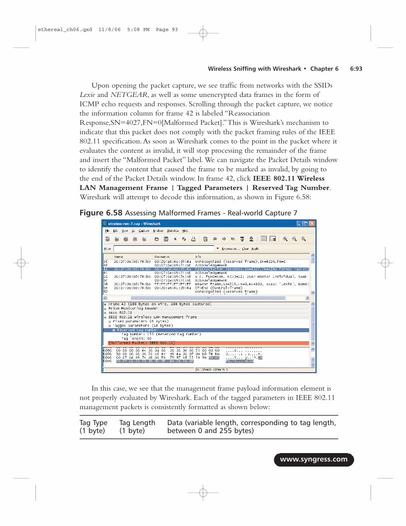
Upon opening the packet capture, we see traffic from networks with the SSIDsLexie and NETGEAR, as well as some unencrypted data frames in the form ofICMP echo requests and responses. Scrolling through the packet capture, we noticethe information column for frame 42 is labeled “ReassociationResponse,SN=4027,FN=0[Malformed Packet].”This is Wireshark’s mechanism toindicate that this packet does not comply with the packet framing rules of the IEEE802.11 specification.As soon as Wireshark comes to the point in the packet where itevaluates the content as invalid, it will stop processing the remainder of the frameand insert the “Malformed Packet” label. We can navigate the Packet Details windowto identify the content that caused the frame to be marked as invalid, by going tothe end of the Packet Details window. In frame 42, click IEEE 802.11 WirelessLAN Management Frame | Tagged Parameters | Reserved Tag Number.Wireshark will attempt to decode this information, as shown in Figure 6.58:
In this case, we see that the management frame payload information element isnot properly evaluated by Wireshark. Each of the tagged parameters in IEEE 802.11management packets is consistently formatted as shown below:
Tag Type Tag Length Data (variable length, corresponding to tag length, (1 byte) (1 byte) between 0 and 255 bytes)
www.syngress.com
Wireless Sniffing with Wireshark • Chapter 6 6:93
Figure 6.58 Assessing Malformed Frames - Real-world Capture 7
ethereal_ch06.qxd 11/8/06 5:08 PM Page 93
In this example, Wireshark identifies the tag number as 155 or 0 ×9b with alength is 65 bytes (0 ×41). However, only 8 bytes remain at the end of the packetbefore the FCS, not 65 as indicated by the frame length.This prompts Wireshark toidentify the packet as malformed.
NOTE
Wireshark identifies this packet as malformed, because the reported taglength exceeds the number of remaining bytes in the packet, andbecause Wireshark knows it has received 100 percent of the bytes in thepacket, as indicated by the frame packet length and capture lengthinformation. However, Wireshark also identifies this tagged parameter asusing a reserved tag number.
Throughout the development of Wireshark, the authors of variousdissectors maintained the software to stay current with the supportedprotocols and the values used in these protocols. However, over time,standards bodies such as the IEEE and IETF may allocate previouslyreserved values for new uses of existing protocols. As such, Wiresharkdoesn’t assume the packet is invalid simply because it does not knowhow to interpret a value that it observed, such as the tag number 155in this example.
Observing a single malformed frame does not suggest that the capture is theproduct of protocol fuzzing techniques or other potentially hostile activity; it is pos-sible that this frame was accidentally corrupted when it was transmitted, or that thestation that is sending this data is flawed and is sending invalid frames. We can easilydetermine if the first condition caused the frame to be malformed by checking thecontents of the FCS field. In frame 42, click IEEE 802.11 | Frame CheckSequence. We see that Wireshark reports the FCS as 0 ×4e2e3e6f, which it reports ascorrect for this packet. While it is possible that the packet could be modified byretaining a valid FCS, it is highly unlikely.As such, we can assume the packet wasreceived in this capture exactly as it was transmitted.
The second possibility of a flawed implementation remains, which would alsosuggest that we would see multiple packets that shared the characteristic of thereserved tag number with a length that is longer than the number of bytes availablein the capture. We can use a display filter to identify other frames that are similar toframe 42, in an attempt to prove/disprove this theory. Right-click on Reserved
www.syngress.com
6:94 Chapter 6 • Wireless Sniffing with Wireshark
ethereal_ch06.qxd 11/8/06 5:08 PM Page 94
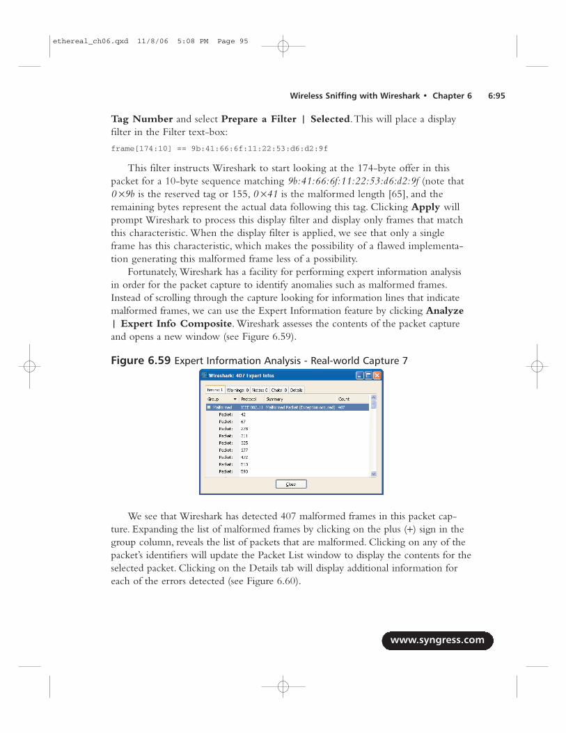
Tag Number and select Prepare a Filter | Selected.This will place a displayfilter in the Filter text-box:
frame[174:10] == 9b:41:66:6f:11:22:53:d6:d2:9f
This filter instructs Wireshark to start looking at the 174-byte offer in thispacket for a 10-byte sequence matching 9b:41:66:6f:11:22:53:d6:d2:9f (note that0 ×9b is the reserved tag or 155, 0 ×41 is the malformed length [65], and theremaining bytes represent the actual data following this tag. Clicking Apply willprompt Wireshark to process this display filter and display only frames that matchthis characteristic. When the display filter is applied, we see that only a singleframe has this characteristic, which makes the possibility of a flawed implementa-tion generating this malformed frame less of a possibility.
Fortunately, Wireshark has a facility for performing expert information analysisin order for the packet capture to identify anomalies such as malformed frames.Instead of scrolling through the capture looking for information lines that indicatemalformed frames, we can use the Expert Information feature by clicking Analyze| Expert Info Composite. Wireshark assesses the contents of the packet captureand opens a new window (see Figure 6.59).
We see that Wireshark has detected 407 malformed frames in this packet cap-ture. Expanding the list of malformed frames by clicking on the plus (+) sign in thegroup column, reveals the list of packets that are malformed. Clicking on any of thepacket’s identifiers will update the Packet List window to display the contents for theselected packet. Clicking on the Details tab will display additional information foreach of the errors detected (see Figure 6.60).
www.syngress.com
Wireless Sniffing with Wireshark • Chapter 6 6:95
Figure 6.59 Expert Information Analysis - Real-world Capture 7
ethereal_ch06.qxd 11/8/06 5:08 PM Page 95
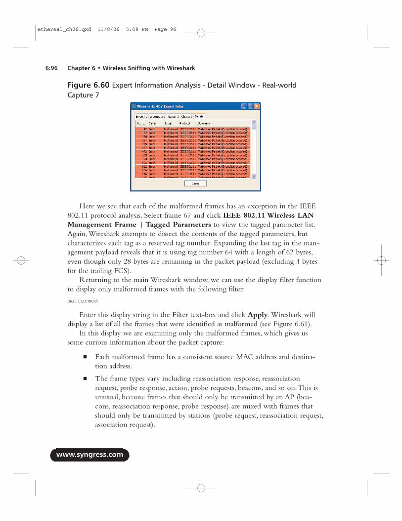
Here we see that each of the malformed frames has an exception in the IEEE802.11 protocol analysis. Select frame 67 and click IEEE 802.11 Wireless LANManagement Frame | Tagged Parameters to view the tagged parameter list.Again, Wireshark attempts to dissect the contents of the tagged parameters, butcharacterizes each tag as a reserved tag number. Expanding the last tag in the man-agement payload reveals that it is using tag number 64 with a length of 62 bytes,even though only 28 bytes are remaining in the packet payload (excluding 4 bytesfor the trailing FCS).
Returning to the main Wireshark window, we can use the display filter functionto display only malformed frames with the following filter:
malformed
Enter this display string in the Filter text-box and click Apply. Wireshark willdisplay a list of all the frames that were identified as malformed (see Figure 6.61).
In this display we are examining only the malformed frames, which gives ussome curious information about the packet capture:
■ Each malformed frame has a consistent source MAC address and destina-tion address.
■ The frame types vary including reassociation response, reassociationrequest, probe response, action, probe requests, beacons, and so on.This isunusual, because frames that should only be transmitted by an AP (bea-cons, reassociation response, probe response) are mixed with frames thatshould only be transmitted by stations (probe request, reassociation request,association request).
www.syngress.com
6:96 Chapter 6 • Wireless Sniffing with Wireshark
Figure 6.60 Expert Information Analysis - Detail Window - Real-worldCapture 7
ethereal_ch06.qxd 11/8/06 5:08 PM Page 96
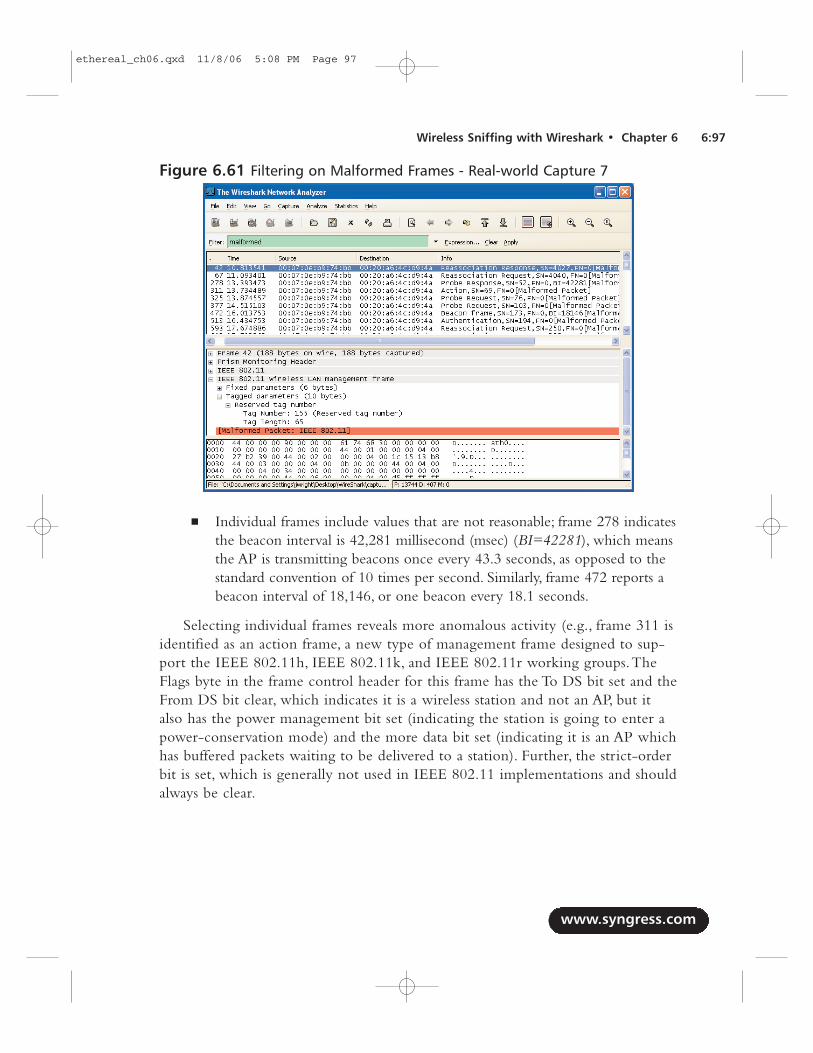
■ Individual frames include values that are not reasonable; frame 278 indicatesthe beacon interval is 42,281 millisecond (msec) (BI=42281), which meansthe AP is transmitting beacons once every 43.3 seconds, as opposed to thestandard convention of 10 times per second. Similarly, frame 472 reports abeacon interval of 18,146, or one beacon every 18.1 seconds.
Selecting individual frames reveals more anomalous activity (e.g., frame 311 isidentified as an action frame, a new type of management frame designed to sup-port the IEEE 802.11h, IEEE 802.11k, and IEEE 802.11r working groups.TheFlags byte in the frame control header for this frame has the To DS bit set and theFrom DS bit clear, which indicates it is a wireless station and not an AP, but italso has the power management bit set (indicating the station is going to enter apower-conservation mode) and the more data bit set (indicating it is an AP whichhas buffered packets waiting to be delivered to a station). Further, the strict-orderbit is set, which is generally not used in IEEE 802.11 implementations and shouldalways be clear.
www.syngress.com
Wireless Sniffing with Wireshark • Chapter 6 6:97
Figure 6.61 Filtering on Malformed Frames - Real-world Capture 7
ethereal_ch06.qxd 11/8/06 5:08 PM Page 97
TIP
A great place to get information about upcoming IEEE 802.11 stan-dards is the IEEE 802.11 timelines page, where each working groupprovides a short summary of the activity of the working group andthe estimated schedule for the ratification of the standard or amend-ment. Linked to each task group is the project authorization requestform and approval letter, which documents the intentions of theworking group and the detailed status page for the activity of theworking group. The IEEE 802.11 timelines page is available athttp://grouper.ieee.org/groups/802/11/Reports/802.11_Timelines.htm.
Our analysis suggests evidence of IEEE 802.11 protocol fuzzing; our “mal-formed” display filter revealed over 400 packets that have conflicting field settingsand reserved field values. However, further analysis also indicates that these 400frames are not the only packets that appear to be the result of protocol fuzzing.Apply the following display filter to identify all frames with the consistent sourceand destination address we have identified for this traffic.
wlan.sa eq 00:07:0e:b9:74:bb and wlan.da eq 00:20:a6:4c:d9:4a
Applying this filter returns 4,580 frames (see Figure 6.62).Even though many of these frames aren’t recognized as malformed by
Wireshark, they appear to have similar characteristics that would lead us to believethat they are also the result of IEEE 802.11 protocol fuzzing. For example, frame 55is reported as a fragmented packet, a feature that is seldom-used in wireless LANs.However, it is also indicating that the station is going to sleep, effectively saying,“Here’s the first part of a packet, now I’m going to sleep, so hold on to this for me.”
From a security researcher’s perspective, Wireshark is an indispensable tool foranalyzing the results of protocol fuzzing activity, assisting in narrowing down theactivity that caused misbehavior in the target station. From an intrusion analysis per-spective, it’s not likely you’ll see this kind of activity on your network, because mostof these packets don’t elicit a response from the target station; rather, a Wireless LocalArea Network (WLAN) IDS system may observe the few frames sent by the attackerto reproduce an identified vulnerability in an effort to exploit a victim system.
www.syngress.com
6:98 Chapter 6 • Wireless Sniffing with Wireshark
ethereal_ch06.qxd 11/8/06 5:08 PM Page 98
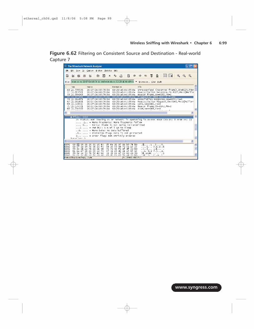
www.syngress.com
Wireless Sniffing with Wireshark • Chapter 6 6:99
Figure 6.62 Filtering on Consistent Source and Destination - Real-worldCapture 7
ethereal_ch06.qxd 11/8/06 5:08 PM Page 99
SummaryPacket sniffing on wireless networks has unique challenges that are different than thechallenges of capturing traffic on wired networks. Fortunately, many wireless cardssupport the ability to capture wireless traffic without needing to connect to a net-work with the monitor mode feature. By leveraging available tools and drivers forWindows and Linux systems, you can use a standard wireless card to capture trafficon the wireless network for analysis.
Wireshark’s wireless analysis features have grown to be a very powerful tool fortroubleshooting and analyzing wireless networks. Leveraging Wireshark’s display fil-ters and powerful protocol dissector features, you can sift through large quantities ofwireless traffic to identify a specific condition or field value you are looking for, orexclude undesirable traffic until you are left with only a handful of traffic to assess.In this chapter, we examined several examples of display filters taken from practicalanalysis needs that you can apply to your own network analysis needs.
Wireshark doesn’t limit itself to display filters for wireless analysis; we can alsotake advantage of other analysis features built into Wireshark to simplify wireless net-work analysis. Features like Wireshark’s coloring rules allow us to leverage display fil-ters to uniquely color-code packets in the Packet List window, which allows you toassess the contents of a packet capture by looking at the number of packets. If yourpacket capture includes radio signal strength information or transmission rate infor-mation, Wireshark can make that information visible as well, giving extra visibilityinto the health and robustness of wireless client connectivity. Finally, when config-ured with the appropriate encryption keys, Wireshark can decrypt traffic dynami-cally, to further simplify the task of network troubleshooting.
Finally, we examined several packet captures taken from production and labwireless environments, to demonstrate Wireshark’s wireless analysis and trou-bleshooting capabilities. Without a doubt, Wireshark is a powerful assessment andanalysis tool for wireless networks that should be a part of every auditor, engineer,and consultant toolkit.
www.syngress.com
6:100 Chapter 6 • Wireless Sniffing with Wireshark
ethereal_ch06.qxd 11/8/06 5:08 PM Page 100
Solutions Fast TrackTechniques for Effective Wireless Sniffing
� Wireless cards can sniff on one channel at a time.
� Channel hopping is used to rapidly change channels and briefly capturetraffic.
� Interference can result in lost traffic and incomplete packet captures.
� Locate the capture station near the station being monitored, while disablingany local transmitters and minimizing CPU utilization.
Understanding Wireless Card Operating Modes
� Wireless card operating modes include managed, master, ad-hoc, andmonitor.
� Monitor mode causes the card to passively capture wireless traffic withoutconnecting to a network.
� Wireless cards do not normally transmit while in monitor mode.
Configuring Linux for Wireless Sniffing
� Linux Wireless Extensions compatible drivers use the iwconfig utility toconfigure monitor mode.
� The Linux MADWIFI drivers for Atheros cards use the wlanconfig utility toconfigure monitor mode.
� Linux Wireless Extensions compatible drivers and the MADWIFI driversuse the iwconfig utility to specify the channel number.
Configuring Windows for Wireless Sniffing
� Windows does not have a built-in mechanism for using a wireless driver inmonitor mode.
� The commercial AirPcap drivers and USB wireless dongle can be used tocapture traffic in monitor mode.
www.syngress.com
Wireless Sniffing with Wireshark • Chapter 6 6:101
ethereal_ch06.qxd 11/8/06 5:08 PM Page 101
Using Wireless Protocol Dissectors
� Frame statistic information is included as the first group of fields in thePacket Details window.
� Protocol dissectors extract and enumerate fields in the IEEE 802.11 headerand payload.
� The IEEE 802.11 header and payload data can be very complex, but thedata is easily assessed with protocol dissectors.
Useful Wireless Display Filters
� Display filters can be applied to any of the fields in the IEEE 802.11 headerand payload data.
� Complex display filters can be built by adding to a filter with AND or ORconditions.
� You can apply inclusive filters when looking for a specific set of data, or toremove uninteresting data from the packet list.
Leveraging Wireshark Wireless Analysis Features
� Coloring rules leverage display filters to identify matching display filterconditions.
� Applying a handful of helpful coloring rules can make it easier to analyzelarge quantities of frames.
www.syngress.com
6:102 Chapter 6 • Wireless Sniffing with Wireshark
ethereal_ch06.qxd 11/8/06 5:08 PM Page 102
Q: Can I use Wireshark for wireless intrusion analysis?
A: Wireshark’s display filter functionality can be used to identify some attacks onwireless networks, such as deauthenticate DoS attacks (wlan.fc.type_subtype eq 12),FakeAP (wlan_mgt.fixed.timestamp < “0 ×000000000003d070”) and NetStumbler(wlan.fc.type_subtype eq 32, llc.oui eq 0x00601d, and llc.pid eq 0x0001), but it is nota replacement for a sophisticated WLAN IDS system.
Q: Can I use Wireshark to crack wireless encryption keys?
A: No, Wireshark does not include any key cracking functionality. Wireshark candecrypt WEP traffic, but only when configured with the correct WEP key.
Q: Can I use Wireshark to analyze traffic captured with Kismet?
A: Yes, Kismet generates several output file types including libpcap files with a .dumpextension. Wireshark can open and assess libpcap files generated with Kismet.
Q: Can I use Wireshark to analyze traffic captured with NetStumbler?
A: No, NetStumbler does not capture traffic in monitor mode and is unable tocreate libpcap files for use with Wireshark.
Q: What is the best card to get for wireless analysis?
A: Wireless cards with an Atheros chipset are known to be effective at capturingwireless traffic on Linux systems, often allowing you to select between IEEE802.11a, 802.11b and 802.11g traffic. Visit the Atheros Product Database athttp://customerproducts.atheros.com/customerproducts/ResultsPageBasic.asp toidentify if a card is based on an Atheros chipset. For Windows hosts, the AirPcapadapter is functional and well-supported by Wireshark, but does not yet supportIEEE 802.11a channels.
www.syngress.com
Wireless Sniffing with Wireshark • Chapter 6 6:103
Frequently Asked Questions
The following Frequently Asked Questions, answered by the authors of this book,are designed to both measure your understanding of the concepts presented in this chapter and to assist you with real-life implementation of these concepts. Tohave your questions about this chapter answered by the author, browse towww.syngress.com/solutions and click on the “Ask the Author” form.
ethereal_ch06.qxd 11/8/06 5:08 PM Page 103
Q: Can I use Wireshark to capture traffic while connected to an AP?
A: When associated to an AP, the wireless card is working in managed mode. Somedrivers allow you to capture traffic in managed mode, but the data is reported asif it were coming from a standard Ethernet interface.This prevents you fromseeing management frames, control frames, and data destined for other networks.
Q: Can Wireshark sniff IEEE 802.11a/b/g/n networks?
A: Wireshark isn’t limited in its ability to sniff any Physical layer wireless networktype, as long as the driver is compatible with libpcap/winpcap and the wirelesscard supports monitor mode for the desired spectrum.At the time of thiswriting we are just starting to see pre-802.11n networks; if your wireless cardand driver support monitor mode for IEEE 802.11n modulation, Wireshark canbe used to analyze the traffic.
Q: How can I examine signal strength information in a Wireshark capture?
A: Wireshark will display signal strength information in any packet capture thatincludes this information in the frame header contents. Some packet capturesonly contain the IEEE 802.11 header contents, which does not include signalstrength information. When capturing traffic for a wireless network, use theRadiotap of Prism AVS link types to record signal strength information.
www.syngress.com
6:104 Chapter 6 • Wireless Sniffing with Wireshark
ethereal_ch06.qxd 11/8/06 5:08 PM Page 104