01 gprs inokia
TRANSCRIPT

8/2/2019 01 Gprs Inokia
http://slidepdf.com/reader/full/01-gprs-inokia 1/138
GPRS in BSC
dn99565086Issue 5-1 en
© Nokia CorporationNokia Proprietary and Confidential
1 (138)
2003282
Nokia BSC S10.5 ED, Product Documentation

8/2/2019 01 Gprs Inokia
http://slidepdf.com/reader/full/01-gprs-inokia 2/138
The information in this document is subject to change without notice and describes only theproduct defined in the introduction of this documentation. This document is intended for the useof Nokia's customers only for the purposes of the agreement under which the document issubmitted, and no part of it may be reproduced or transmitted in any form or means without theprior written permission of Nokia. The document has been prepared to be used by professionaland properly trained personnel, and the customer assumes full responsibility when using it.Nokia welcomes customer comments as part of the process of continuous development andimprovement of the documentation.
The information or statements given in this document concerning the suitability, capacity, or performance of the mentioned hardware or software products cannot be considered binding butshall be defined in the agreement made between Nokia and the customer. However, Nokia hasmade all reasonable efforts to ensure that the instructions contained in the document areadequate and free of material errors and omissions. Nokia will, if necessary, explain issueswhich may not be covered by the document.
Nokia's liability for any errors in the document is limited to the documentary correction of errors.NOKIA WILL NOT BE RESPONSIBLE IN ANY EVENT FOR ERRORS IN THIS DOCUMENTOR FOR ANY DAMAGES, INCIDENTAL OR CONSEQUENTIAL (INCLUDING MONETARYLOSSES), that might arise from the use of this document or the information in it.
This document and the product it describes are considered protected by copyright according tothe applicable laws.
NOKIA logo is a registered trademark of Nokia Corporation.
Other product names mentioned in this document may be trademarks of their respectivecompanies, and they are mentioned for identification purposes only.
Copyright © Nokia Corporation 2003. All rights reserved.
2 (138) © Nokia CorporationNokia Proprietary and Confidential
dn99565086Issue 5-1 en
GPRS in BSC

8/2/2019 01 Gprs Inokia
http://slidepdf.com/reader/full/01-gprs-inokia 3/138
Contents
Contents 3
List of tables 5
List of figures 6
Summary of changes 7
1 GPRS in BSC 91.1 GPRS in BSC Overview 121.2 Software and hardware requirements of GPRS 131.2.1 Packet Control Unit (PCU) 141.2.2 Gb interface functionality 16
1.2.3 Additional hardware for GPRS needed by the other BSC models thanBSC3i 19
1.3 GPRS Interoperability 191.3.1 Interaction of GPRS with other BSC features 21
2 GPRS parameters in BSC 292.1 Radio Network parameters for GPRS 292.2 Dynamic Abis Pool Handling parameters 312.3 Radio Network parameters for EGPRS 322.4 Radio Network parameters for PBCCH/PCCCH 332.5 Radio Network parameters for Priority Based Scheduling 342.6 Radio Network parameters for GSM-WCDMA cell re-selection 352.7 PAFILE parameters 362.8 PRFILE parameters 37
3 GPRS statistics in BSC 413.1 GPRS-specific measurements 413.2 GPRS-related counters in other measurements 443.3 System level trace for GPRS in BSC 46
4 GPRS alarms in BSC 49
5 Radio network management for GPRS in BSC 515.1 Routing Area 515.2 PCU selection algorithm 54
5.3 Neighbouring cell 555.4 Packet control channels 55
6 Gb interface configuration and state management 576.1 The protocol stack of the Gb interface 576.2 Load sharing function 596.3 NS-VC management function 606.4 BVC management function 646.5 Recovery in restart and switchover 66
dn99565086Issue 5-1 en
© Nokia CorporationNokia Proprietary and Confidential
3 (138)
Contents

8/2/2019 01 Gprs Inokia
http://slidepdf.com/reader/full/01-gprs-inokia 4/138
7 Dynamic Abis 697.1 Dynamic Abis Pool management 697.2 EGPRS Dynamic Abis Pool connections 727.3 Capacity of Dynamic Abis 73
7.4 Error conditions in Dynamic Abis 767.5 Restrictions to Dynamic Abis 77
8 Radio resource management 818.1 Territory method 828.2 Circuit switched traffic channel allocation in GPRS territory 918.3 BTS selection for packet traffic 928.4 Quality of Service 948.5 Channel allocation and scheduling 958.6 Error situations in (E)GPRS connections 100
9 GPRS radio connection control 103
9.1 Radio channel usage 1039.2 Paging 1069.3 Mobile terminated TBF (GPRS or EGPRS) 1109.4 Mobile originated TBF (GPRS or EGPRS) 1139.5 Suspend and resume GPRS 1209.6 Flush 1219.7 Cell selection and reselection 1229.8 Traffic administration 1239.9 Coding scheme selection in GPRS 1279.10 Coding scheme selection in EGPRS 1329.11 Power control 135
10 Limitations of the (E)GPRS feature 137
4 (138) © Nokia CorporationNokia Proprietary and Confidential
dn99565086Issue 5-1 en
GPRS in BSC

8/2/2019 01 Gprs Inokia
http://slidepdf.com/reader/full/01-gprs-inokia 5/138
List of tables
Table 1. NS-VC operational states 60
Table 2. BVC operational states 65
Table 3. Coding scheme. Need for master (M) and slave channels (S) on Abis(EDAP) 75
Table 4. Defining the margin of idle TCH/Fs 86
Table 5. Defining the margin of idle TCHs, % 89
Table 6. Supported Network Operation Modes 106
Table 7. EGPRS Coding Schemes 132
dn99565086Issue 5-1 en
© Nokia CorporationNokia Proprietary and Confidential
5 (138)
List of tables

8/2/2019 01 Gprs Inokia
http://slidepdf.com/reader/full/01-gprs-inokia 6/138
List of figures
Figure 1. BSS relation to the GPRS network 10
Figure 2. PCU connections to BTS and SGSN 16
Figure 3. Protocol stack of the Gb interface 17
Figure 4. Gb interface between the BSC and SGSN 18
Figure 5. Relationship of Routing Areas and PCUs 52
Figure 6. The protocol stack on the Gb interface 57
Figure 7. Territory method in BSC 83
Figure 8. GPRS territory upgrade when a time slot is cleared for GPRS use with an
intra cell handover 85
Figure 9. PS page and CS page in GPRS 108
Figure 10. Uplink power control 136
6 (138) © Nokia CorporationNokia Proprietary and Confidential
dn99565086Issue 5-1 en
GPRS in BSC
8/2/2019 01 Gprs Inokia
http://slidepdf.com/reader/full/01-gprs-inokia 7/138
Summary of changes
Summary of changes
Changes between document issues are cumulative. Therefore, the latest document
issue contains all changes made to previous issues.
Changes made between issues 05V and 05
A warning about sharing a Dynamic Abis Pool between more than one BCF
cabinets added.
Information about BTS selection for packet traffic added.
Changes made between issues 05 and 04
Changes related to Dynamic Abis included.
A note about not creating PBCCH/PCCCH channels in NMO II has been added.
Information about MS synchronisation in GPRS and EGPRS cases has been
added.
Information about IP as an alternative to Frame Relay as the Gb interface protocol
removed.
Changes made between issues 04 and 03
Changes due to Gb over IP
Information about IP as an alternative to Frame Relay as the Gb interface protocol
added.
Changes due to BSC3i
The different hardware of the BSC3i has been taken into consideration in the
document.
Changes made between issues 03 and 02
GPRS-related changes
Added information about the possibility to include a second PCU to the BCSU in
BSC2A, BSC2E and BSC2i.
The explanation of the PCU selection algorithm has also been corrected.
dn99565086Issue 5-1 en
© Nokia CorporationNokia Proprietary and Confidential
7 (138)
Summary of changes

8/2/2019 01 Gprs Inokia
http://slidepdf.com/reader/full/01-gprs-inokia 8/138
8 (138) © Nokia CorporationNokia Proprietary and Confidential
dn99565086Issue 5-1 en
GPRS in BSC

8/2/2019 01 Gprs Inokia
http://slidepdf.com/reader/full/01-gprs-inokia 9/138
1 GPRS in BSC
The function of the following features in the BSC is described here: BSS9006:
GPRS , BSS10083: EGPRS , BSS10074: Support of PCCCH /PBCCH,
BSS10084: Quality of Service, BSS10045: Dynamic Abis allocation.
This text is applicable for both ANSI and ETSI environments.
GPRS provides packet data radio access for GSM mobile phones. GPRS is well
adapted to burst data applications, and it upgrades GSM data services to allow an
interface with Local Area Networks (LAN s), Wide Area Networks (WAN s), and
the Internet.
GPRS uses the radio interface efficiently in two ways. Firstly, it enables a fast
method for reserving radio channels. Secondly, the benefit of GPRS is the sharing
of resources with circuit switched connections. GPRS packets can be transmitted
in the free periods between circuit switched calls. Furthermore, GPRS provides
immediate connectivity and high throughput.
On a general level, GPRS connections use the resources only for a short time
when they are sending or receiving data. When the user is ready to receive new
data, the terminal sends a request, and resources are again reserved only for the
duration of transmitting the request and initiating a second data transfer. The data
to be transferred is encapsulated into short packets with a header containing the
originating and destination address. No pre-set time slots are used. Instead,
network capacity is allocated when needed and released when not needed. This is
called statistical multiplexing, in contrast to static time division multiplexing,
where time slots are reserved for one user for the length of the connection,
regardless of whether it is used or not, as with PCM lines and GSM voice and
circuit switched data.
GPRS offers a very flexible range of bitrates, from less than 100 bit/s to over 100
kbit/s. Applications that need less than one time slot benefit from GPRS's ability
to share one time slot among several users. Moreover, the high bitrates that GPRS
provides by using multiple time slots give short response times, even if a lot of
data is transmitted.
The main functions of the BSC with GPRS are to:
dn99565086Issue 5-1 en
© Nokia CorporationNokia Proprietary and Confidential
9 (138)
GPRS in BSC

8/2/2019 01 Gprs Inokia
http://slidepdf.com/reader/full/01-gprs-inokia 10/138
" manage GPRS-specific radio network configuration
" control access to GPRS radio resources
" share radio resources between GPRS and circuit switched use
" handle signalling between the MS, BTS and Serving GPRS Support Node
(SGSN)
" transfer GPRS data.
The figure below illustrates the GPRS network and how the Base Station
Subsystem is related to the core network.
Figure 1. BSS relation to the GPRS network
Enhanced Data Rates for Global Evolution (EDGE) provides services such as
Enhanced GPRS (EGPRS) allowing higher data rates than current GPRS
configurations. The Nokia EDGE Solution includes EGPRS for the packet
switched data. EGPRS uses nine modulation and coding schemes (MCS) which
vary from 8.8 kbps up to 59.2 kbps with one time slot in the radio interface.
Corporate Server
Localareanetwork
Router
HLR/ AuC
MSC
BSCBTS
PSTN
Firewall
Firewall
Firewall
R/S
SMS-GMSC
EIR
IP SUBNETWORK155.222.33.XXX
Serving GPRSSupport Node
(SGSN)
Border Gateway (BG)
Inter-PLMNBackbone
network
Point-To-MultipointServiceCenter (PTM SC)
Gateway GPRS
Support Node(GGSN)
SS7Network
GPRS
INFRASTRUCTURE
Datanetwork(X.25)
Datanetwork(Internet)
Intra-PLMNbackbonenetwork
(IP based)
10 (138) © Nokia CorporationNokia Proprietary and Confidential
dn99565086Issue 5-1 en
GPRS in BSC

8/2/2019 01 Gprs Inokia
http://slidepdf.com/reader/full/01-gprs-inokia 11/138
Due to GPRS traffic increase, more capacity is needed for the packet common
control signalling. This will bring dedicated CCCH capacity for (E)GPRS
services. The PCCCH comprises logical channels for packet common control
signalling.
Basically all TBFs (in GPRS calls) have the same priority, that is, all users and
all applications get the same service level. The needs of different applications
differ and mechanisms to have separate service levels are required. ETSI
specifications define QoS functionality which gives the possibility to differentiate
TBFs by delay, throughput and priority. Priority Based Scheduling is introduced
as a first step towards QoS. With Priority Based Scheduling the operator can give
users different priorities. Higher priority users will get better service than lower
priority users. There will be no extra blocking to any user, only the experienced
service quality changes.
Benefits for the operator
GPRS has minimal effects on the handling of circuit switched calls, but the
interoperability of existing circuit switched features needs to be taken into
consideration (refer to Interoperability for more information). Nevertheless,
GPRS does offer additional benefits for the operator:
" resources are better used, thus there is less idle time
" circuit switched traffic is prioritised, but quality is guaranteed by reserving
time slots only for GPRS traffic
" new services, applications, and business for the operator
" fast connection setup for end-users
" high bitrate in data bursts, up to 100 kbit/s (for end-users).
Enhanced Data Rates for Global Evolution (EDGE) provides services such as
Enhanced GPRS (EGPRS) allowing higher data rates than previous GPRS
configurations. EGPRS furthermore offers the operator the following benefits:
" Migration to wireless multimedia services. The operator could increase
data revenues by offering completely new types of attractive services to
end-users.
" Fast network implementation. EDGE capability can be introduced
incrementally in the network.
" Optimised network investment as GSM enhancement. Flexible data
capacity deployment where the demand is.
dn99565086Issue 5-1 en
© Nokia CorporationNokia Proprietary and Confidential
11 (138)
GPRS in BSC
8/2/2019 01 Gprs Inokia
http://slidepdf.com/reader/full/01-gprs-inokia 12/138
1.1 GPRS in BSC Overview
GPRS in BSC " Overview of GPRS in BSC
" Software and hardware requirements of GPRS
" GPRS Interoperability
GPRS parameters in BSC
" Radio Network parameters for GPRS
" Dynamic Abis Pool Handling parameters
" Radio Network parameters for EGPRS
" Radio Network parameters for PBCCH/PCCCH
" Radio Network parameters for Priority Based Scheduling
"
PRFILE parameters
GPRS statistics in BSC
" GPRS specific measurements
" GPRS related counters in other measurements
" System level trace for GPRS in BSC
GPRS alarms in BSC
Radio network management for GPRS in BSC
" Routing Area
" PCU selection algorithm
" Neighbouring cell" Packet control channels
Gb interface configuration and state management
" The protocol stack of the Gb interface
" Load sharing function
" NS-VC management function
" BVC management function
" Recovery in restart and switchover
Dynamic Abis
" Dynamic Abis Pool management
" EGPRS Dynamic Abis Pool connections
" Capacity
" Error conditions in Dynamic Abis
" Restrictions to Dynamic Abis
12 (138) © Nokia CorporationNokia Proprietary and Confidential
dn99565086Issue 5-1 en
GPRS in BSC

8/2/2019 01 Gprs Inokia
http://slidepdf.com/reader/full/01-gprs-inokia 13/138
Radio resource management
" Territory method
" Circuit switched traffic channel allocation in GPRS territory
"
Quality of service" Channel allocation and scheduling
" Error situations in GPRS connection
GPRS radio connection control
" Radio channel usage
" Paging
" Mobile terminated GPRS TBF
" Mobile originated GPRS TBF
" Suspend and resume GPRS
" Flush
" Cell selection and reselection
" Traffic administration
" Coding scheme selection in GPRS
" Coding scheme selection for EGPRS
" Power control
Limitations of the (E)GPRS feature
1.2 Software and hardware requirements of GPRS
The BSC software releases from S9 onwards support GPRS.
The hardware needed for GPRS to function in the BSC are Packet Control Unit
(PCU), Gb interface functionality between the BSC and Serving GPRS Support
Node (SGSN), GSWB extension, and ET5C cartridge (optional).
In general, the BSC S10.5 network element HW supports all existing
functionalities and their implementation principles. BSC S10.5 does not require
any cabling or cartridge changes to the basic configurations of BSCE, BSCi,
BSC2E, BSC2A, BSC2i and BSC3i. All modifications to the HW cabling or
cartridge are related to the optional EDGE feature.
By the implementation of EDGE (Enhanced Data Rates for Global Evolution) a
new service such as Enhanced GPRS (EGPRS) can allow higher data rates than
current GPRS configurations. EGPRS can be implemented for the BSC with S9
level GPRS PCUs. However, a new configuration has been created for BSC2E/A
and BSC2i, with the possibilitly to add a second PCU (PCU-S or PCU-T plug-in
dn99565086Issue 5-1 en
© Nokia CorporationNokia Proprietary and Confidential
13 (138)
GPRS in BSC

8/2/2019 01 Gprs Inokia
http://slidepdf.com/reader/full/01-gprs-inokia 14/138
unit) per BCSU unit (8+1) to further increase the packet processing capacity. The
implementation of a second PCU also requires a GSWB extension from 192 to
256 PCMs. Correspondingly the number of ETs can be extended from 112 to 144
in BSC2s.
BSC3i has two PCU-B plug-in units in each BCSU that each contain two logical
PCUs. So in essence, BSC3i has four PCUs per BCSU.
Additional or optional hardware for EGPRS for BSC3i
" Two PCU-B plug-in units
Additional or optional hardware for EGPRS for other BSCs
" PCU-S or PCU-T PIU and DMCT2-S terminator if not already installed.
" Two additional ET5C-cartridges.
" Fourth SW64B PIU and the SWBUS4 connector to the GSWB.
" AS7-X replaces AS7-V and AS7-VA in new deliveries.
More information on GPRS in BSC:
GPRS in BSC
GPRS in BSC Overview
Interoperability
1.2.1 Packet Control Unit (PCU)
For GPRS the BSC needs the Packet Control Unit, which implements both the
Gb interface and RLC /MAC protocols in the BSS. The Nokia implementation of
the PCU is in the BSC.
PCU functions
The PCU controls the GPRS radio resources and acts as the key unit in the
following procedures:
" GPRS radio resource allocation and management
" GPRS radio connection establishment and management
" data transfer
14 (138) © Nokia CorporationNokia Proprietary and Confidential
dn99565086Issue 5-1 en
GPRS in BSC

8/2/2019 01 Gprs Inokia
http://slidepdf.com/reader/full/01-gprs-inokia 15/138
" coding scheme selection
" PCU statistics.
PCU capacity and connections
Two 2 Mbit/s PCM lines are connected through the GSWB to the Abis interface,
and one 2 Mbit/s line to the Gb interface towards the SGSN. Each BCSU has to
have equal number of PCU(s), either one or two. Refer to Enabling GPRS in BSC
for instructions on how to equip and connect the PCU, and to PCU for more
information on the plug-in unit hardware.
One PCU can handle the GPRS traffic of 256 radio time slots, and the maximum
number of connected traffic channels (16kbit/s) in GPRS use in a BSS is 2048
(that is, 8 times 256) for BSCE and BSCi, 4096 (16 times 256) for BSC2A,
BSC2E and BSC2i, and 6144 (24 times 256) for BSC3i. Furthermore, one PCUcan handle a maximum of 64 BTSs and 128 TRXs. This means that at least four
active PCUs are required to handle the maximum number of BTSs (248) of one
BSC.
The EGPRS modifications have an effect on the PCU memory demand due to the
larger RLC data block size and possible use of large RLC window size. Once a
window size is selected for a given MS, it may be changed to a larger size but not
to a smaller size, in order to prevent dropping data blocks from the window.
Therefore, if a TBF is reallocated so that the number of allocated timeslots is
reduced, the RLC window size may become larger than the maximum window
size for the new resources.
There are some limitations to the PCU:
" in one PCU, only 16 DAPs can be created
" in one PCU there can be only 256 channels (including PBCCH/PCCCH +
default GPRS + EDAP channels)
" having more than 204 EDAP channels in one PCU is not recommended
(requires space for at least 1 master channel per 4 slave channels)
There are also some limitations to the radio network:
" the maximum number of DAPs is 470
" The theoretical maximum number of TRXs per DAP is 20. However, since
TRXs using DAP resources must be allocated to the same Abis ETPCM
line with EDAP, the maximum TRX count for a DAP is 12 in the ETSI
environment and 8 in the ANSI environment.
dn99565086Issue 5-1 en
© Nokia CorporationNokia Proprietary and Confidential
15 (138)
GPRS in BSC

8/2/2019 01 Gprs Inokia
http://slidepdf.com/reader/full/01-gprs-inokia 16/138
" one EDGE synchronisation master channel per TRX must exist (EGPRS
limitation)
" the serving PCU must be the same for all the TRXs under one segment (for
more information, see Restrictions to Dynamic Abis )
Figure 2. PCU connections to BTS and SGSN
More information on software and hardware requirements of GPRS:
Gb interface functionality
Additional hardware for GPRS needed by the older BSC models
Back to GPRS in BSC Overview.
1.2.2 Gb interface functionality
The Gb interface is an open interface between the BSC and the SGSN. Theinterface consists of the Physical Layer, Network Service layer (NS), and the
Base Station Subsystem GPRS Protocol (BSSGP). The layers are briefly
described here, but their functions are discussed in more detail in Gb interface
configuration and state management .
SGSN
ETs
ETs
ET
DMC bus
PCU
GSWB
Packets in FR
AbisGb
FR: bearer channel + optionalload sharing redundant bearer (2 Mbit/s)
Packets inTRAU frames
4 Mbit/s internal PCM256 channels
16 (138) © Nokia CorporationNokia Proprietary and Confidential
dn99565086Issue 5-1 en
GPRS in BSC

8/2/2019 01 Gprs Inokia
http://slidepdf.com/reader/full/01-gprs-inokia 17/138
Figure 3. Protocol stack of the Gb interface
The BSSGP protocol functions are BSSGP protocol encoding and decoding,
BSSGP virtual connection (BVC ) management, BSSGP data transfer, paging
support, and flow control support.
The Network Service Control is responsible for NS protocol encoding and
decoding, NS data transfer, NS Service Data Unit (NS SDU) transmission, uplink
congestion control on Network Service Virtual Connection (NS-VC ), load
sharing between NS-VCs, NS-VC state management, and GPRS-specific
addressing, which maps cells to virtual connections.
The Frame Relay protocols provide a link layer access between the peer entities.
Frame Relay offers permanent virtual circuits (PVC ) to transfer GPRS signalling
and data between the BSC and SGSN.
The Gb interface may consist of direct point-to-point connections between the
BSS and the SGSN, or an intermediate Frame Relay network may be placed
between both ends of the Gb interface. In the case of an intermediate Frame Relay
network, both BSS and SGSN are treated as the user side of the user-to-network
interface.
In FR, the physical link is provided by the Frame Relay Bearer channels. In the
BSC this physical connection is a maximum of one 2 Mbit/s PCM for each active
PCU. For load sharing and transmission security reasons, one PCU can have up
to four Frame Relay Bearer channels that are routed to the SGSN through
different transmission paths. This means that the GPRS traffic from one PCU can
be shared with a maximum of four physical PCM connections. The PCUs cannot
be multiplexed to use a common bearer.
SGSNGbBSS
L1
NS
BSSGP
RELAY
RLC
MAC
LLC
BSSGP
NS
L1
dn99565086Issue 5-1 en
© Nokia CorporationNokia Proprietary and Confidential
17 (138)
GPRS in BSC

8/2/2019 01 Gprs Inokia
http://slidepdf.com/reader/full/01-gprs-inokia 18/138
The maximum combined Bearer Channel Access Rate in both the ETSI and
ANSI environments is 2048 kbit/s within a PCU. This can be achieved by
combining the different PCMs so that 32 subtimeslots are available for traffic.
The step size is 64 kbit/s. The Committed Information Rate of Network Service
Virtual Connections can be configured from 16 kbit/s up to the Access Rate of the
Bearer channel in 16 kbit/s steps.
In the Nokia implementation each PCU represents one and only one Network
Service Entity (NSE).
Figure 4. Gb interface between the BSC and SGSN
For more information on the NS and BSSGP protocols, refer to BSC-SGSN
Interface Specification, Network Service Protocol (NS) and BSC-SGSN Interface
Specification, BSS GPRS Protocol (BSSGP) .
The following references, on the other hand, will give you more information on
the configuring and handling of the Gb interface: Enabling GPRS in BSC , Frame Relay Bearer Channel Handling , and Frame Relay Parameter Handling .
More information on software and hardware requirements of GPRS:
Packet Control Unit (PCU)
Additional hardware for GPRS needed by the older BSC models
BCSU 0
GSWB
FR
PCU
ET
PCM-TSL
bearer channelID=1name=BSC1time slots:1-31
access rate:1984 kbit/s
SGSN
BSC
18 (138) © Nokia CorporationNokia Proprietary and Confidential
dn99565086Issue 5-1 en
GPRS in BSC

8/2/2019 01 Gprs Inokia
http://slidepdf.com/reader/full/01-gprs-inokia 19/138
Back to GPRS in BSC Overview.
1.2.3 Additional hardware for GPRS needed by the other BSC models thanBSC3i
GSWB extension (optional)
The PCU requires the GSWB extension (2 per BSC) for multiplexing the 256
Abis sub-time-slots into it. The second PCU card for the BSC unit requires an
extension of the GSWB with a third SW64B plug-in unit.
ET5C cartridge (optional)
Additional ET5C cartridges are optional as they are not needed for GPRS.
However, they are needed to increase the PCMs from 80 to 112. In the S8optional upgrade to High Capacity BSC they have been added.
AS7-X, Adapter for CCS7 signalling
The AS7-X is a multichannel signalling link terminal for data or signalling using
the HDLC format. The capacity of the AS7-X is the same as the AS7-Vand AS7-
VA. The memory architecture in AS7-X pre-processor units is based on the
SRAM .
The capacity of the AS7-X is as follows:
" 16 CCS7 links, or
" 64 LAPD channels, or
" digital X.25
AS7-X replaces AS7-V and AS7-VA in new deliveries.
More information on software and hardware requirements of GPRS:
Packet Control Unit (PCU)
Gb interface functionality
Back to GPRS in BSC Overview.
1.3 GPRS Interoperability
This section describes how the existing features of the BSC interact with GPRS.
dn99565086Issue 5-1 en
© Nokia CorporationNokia Proprietary and Confidential
19 (138)
GPRS in BSC

8/2/2019 01 Gprs Inokia
http://slidepdf.com/reader/full/01-gprs-inokia 20/138
System viewpoint
GPRS needs a number of new network elements and new functionalities.
The new network elements are Serving GPRS Support Nodes (SGSN), Gateway
GPRS Support Nodes (GGSN), GPRS backbone, and the Point-to-multipoint
Service Centre (PTM SC).
In addition, mobile stations need to be capable of handling GPRS traffic, and
software upgrades are required in BTSs, MSC/VLRs and HLRs, NMSs, and the
BSCs. BSC releases from S9 onwards support GPRS.
On the functionality side GPRS requires the following:
" GPRS-specific mobility management, where the location of the MS is
handled separately by the SGSN and by the MSC/VLR even if some
cooperation exists
" the network management must be capable of handling the GPRS-specific
elements
" new security features for the GPRS backbone
" a new ciphering algorithm
" a new radio interface (Um) for packet data traffic
" new MAP and GPRS-specific signalling.
For the full use of GPRS all these need to be taken into consideration. The latter
two radio interface and GPRS signalling are relevant to the functioning of
the BSC.
EGPRS requires the following new network elements and new functionalities:
" new EDGE-capable TRX
" new EDGE-capable MS
" software upgrade to BSC
EGPRS network elements
Nokia EDGE -capable TRXs for the Nokia MetroSite EDGE BTS and the
UltraSite EDGE BTS are compatible with GSM TRXs. In addition to providing
Nokia EDGE services, Nokia EDGE TRXs are fully GSM-compatible and
support GSM voice, data, HSCSD, GPRS and EGPRS. They are also backward
compatible with all legacy GSM mobiles.
20 (138) © Nokia CorporationNokia Proprietary and Confidential
dn99565086Issue 5-1 en
GPRS in BSC

8/2/2019 01 Gprs Inokia
http://slidepdf.com/reader/full/01-gprs-inokia 21/138
The Nokia Talk-family BTS site can be upgraded to Nokia EDGE functionality
with the installation of a Nokia UltraSite EDGE BTS (housing Nokia EDGE-
capable TRXs) on the site as an extension cabinet. Site compatibility is achieved
with the synchronisation of Nokia Talk-family BTS and Nokia UltraSite EDGE
BTS and by using existing antenna and feeding structures. The synchronized
BTSs share a single BCCH (per sector) and function in the network as a single
cell. The site is then seen as one object by the NMS and the BSC (Multi BCF
control feature). In this configuration, the Nokia Talk-family TRXs support voice,
9.6 kbits data, HSCSD and GPRS.
More information on GPRS in BSC:
GPRS in BSC
GPRS in BSC Overview
Software and hardware requirements of GPRS
More about GPRS interoperability:
1.3.1 Interaction of GPRS with other BSC features
The implementation of GPRS causes changes to the following existing functions
of the BSC:
" the PCU plug-in unit is introduced in Hardware ConfigurationManagement
" GPRS-related radio network parameters are introduced in Radio Network
Configuration Management
" co-operation between circuit switched traffic and GPRS traffic is defined in
Radio Channel Allocation
" GPRS traffic is monitored by GPRS-specific measurements and counters
" the serving PCU must be same for all the TRXs under one segment.
The implementation is described in detail in Radio network management for
GPRS in BSC , Gb interface configuration and state management , Radio
resource management , and GPRS radio connection control . GPRS statistics in
BSC introduce the new GPRS measurements.
In the BSC the introduction of GPRS means dividing the radio resources
circuit switched and GPRS traffic into two territories. This has an effect on the
radio channel allocation features in which the BSC makes decisions based on the
load of traffic. For some features only the resources of the circuit switched
dn99565086Issue 5-1 en
© Nokia CorporationNokia Proprietary and Confidential
21 (138)
GPRS in BSC
8/2/2019 01 Gprs Inokia
http://slidepdf.com/reader/full/01-gprs-inokia 22/138
territory are included in the decisions. However, for most features also the traffic
channels in the GPRS territory need to be taken into consideration when the BSC
defines the traffic load, because radio time slots (RTSL) in the GPRS territory
may be allocated for circuit switched traffic if necessary. Only if there are radio
time slots that are permanently reserved for GPRS use (dedicated GPRS
resources), these cannot be used for circuit switched calls and the BSC totally
excludes these in its decisions on traffic load.
Extended Cell Range
Cell resources in the extended area of a cell are not used for GPRS.
Note
Packet control channels cannot be used with Extended Cell Range.
Frequency Hopping
In Baseband hopping radio time slot 0 belongs to a different hopping group from
other radio time slots of a TRX. This makes radio time slot 0 unusable for
multislot connections. If Baseband hopping is employed in a BTS, radio time slot
0 of any TRX in the BTS will not be used for GPRS.
Both RF and Baseband hopping are supported in EGPRS.
Optimisation of the MS Power Level
The BSC attempts to allocate the traffic channels within the circuit switched
territory according to the interference level recommendation the BSC has
calculated, in order to allow the performing of optimisation of the MS power
level. When the BSC has to allocate a traffic channel for a circuit switched
request in the GPRS territory, the interference level recommendation is no longer
the guiding factor. Now the first GPRS radio time slot beside the territory border
is taken regardless of its interference level being among the recommended ones or
not. Refer to Radio resource management for more information on the division
of territories.
Intelligent Underlay-Overlay
Super-reuse frequencies are not supported for GPRS.
22 (138) © Nokia CorporationNokia Proprietary and Confidential
dn99565086Issue 5-1 en
GPRS in BSC

8/2/2019 01 Gprs Inokia
http://slidepdf.com/reader/full/01-gprs-inokia 23/138
Dynamic Hot Spot
For the Dynamic Hot Spot feature also the possible traffic on the GPRS channels
is meaningful. The radio time slots in GPRS traffic are regarded as busy channels
in the algorithms of the Dynamic Hot Spot feature during traffic channel
allocation. On the other hand, the BSC applies the Dynamic Hot Spot algorithm
when it allocates radio time slots for GPRS use in case the radio time slots are
above and beyond the operator-defined GPRS territory. When allocating the
default GPRS territory that the operator has defined with the parameter default
GPRS capacity (CDEF) , the BSC does not apply the Dynamic Hot Spot
algorithm.
Dynamic SDCCH allocation
The BSC selects a traffic channel time slot to be reconfigured as a dynamic
SDCCH time slot always within the circuit switched territory.
TRX prioritisation in TCH allocation
The operator can set the BCCH TRX or the non-BCCH TRXs as preferred for the
GPRS territory with the parameter prefer BCCH frequency GPRS (BFG) .
This parameter indicates whether the same or the opposite preference is used for
GPRS as is used for circuit switched traffic, indicated by the parameter TRX
priority in TCH allocation (TRP) . If no preference is indicated, then
no prioritisation will be used between different TRX types when forming the
GPRS territory either.
Trunk reservation
In trunk reservation the BSC defines the number of idle traffic channels. The BSC
adds together the number of idle traffic channels in the circuit switched territory
and the number of traffic channels in the radio time slots of the GPRS territory,
excluding the ones that are in the radio time slots that the BSC has allocated
permanently for GPRS.
TRX fault
When a TRX carrying traffic channels becomes faulty, the radio time slots on the
TRX are blocked from use. The BSC releases the possible ongoing calls and thecall control resources. The BSC downgrades the traffic channels belonging to the
GPRS territory in the faulty TRX from GPRS use. To replace the lost GPRS
capacity the BSC determines the possibility of a GPRS territory upgrade in
another TRX. Refer to Radio resource management for more information on
GPRS territory upgrades and downgrades.
If the faulty TRX functionality is reconfigured to another TRX in the cell, the
GPRS-enabled TRX is also transferred to the new TRX.
dn99565086Issue 5-1 en
© Nokia CorporationNokia Proprietary and Confidential
23 (138)
GPRS in BSC

8/2/2019 01 Gprs Inokia
http://slidepdf.com/reader/full/01-gprs-inokia 24/138
If the faulty TRX is EDGE-capable, and GPRS in enabled in the TRX and
EGPRS is enabled in the BTS, the system tries to reconfigure its functionality to
another EDGE-capable TRX in the BTS.
Resource indication to MSC
In general the BSCs indication on the resources concerns traffic channels of a
BTS excluding those allocated permanently to GPRS (dedicated GPRS channels).
GPRS territory resources other than the dedicated ones are regarded as working
and idle resources.
Half Rate
Permanent type half rate time slots are not used for GPRS traffic. Thus it is
recommended not to configure permanent half rate time slots in TRXs that are
planned to be capable of GPRS.
When the BSC can select the channel rate (full rate or half rate) to be used for a
circuit switched call based on the traffic load of the target BTS, the load limits
used in the procedure are calculated using the operator defined BSC and BTS
parameters lower limit for HR TCH resources (HRL) , upper limit
for HR TCH resources (HRU) , lower limit for FR TCH resources
(FRL) , and upper limit for FR TCH resources (FRU) and the
resources of the circuit switched territory of the BTS only.
High Speed Circuit Switched Data (HSCSD)
If GPRS has been enabled in a BTS, the HSCSD-related load limits are calculated
based on the existing HSCSD parameters and the following rules:
" the number of working resources includes all the working TCH/F
resources of a BTS, excluding the ones that have been allocated
permanently to GPRS
" the number of occupied TCH/F resources includes all the occupied TCH/
Fs of the circuit switched territory, as well as the default GPRS territory
TCH/Fs, excluding the GPRS radio time slots defined as dedicated
" HSCSD parameter HSCSD cell load upper limit (HCU) is
replaced with the radio network GPRS parameter free TSL for CS
downgrade (CSD) if the latter is more restricting; thus the one is used
that limits HSCSD traffic earlier.
The parameter free TSL for CS downgrade (CSD) defines a margin of
radio time slots that the BSC tries to preserve idle for circuit switched traffic by
downgrading the GPRS territory when necessary.
24 (138) © Nokia CorporationNokia Proprietary and Confidential
dn99565086Issue 5-1 en
GPRS in BSC

8/2/2019 01 Gprs Inokia
http://slidepdf.com/reader/full/01-gprs-inokia 25/138
If HSCSD multislot allocation is denied based on the appropriate parameters, the
BSC rejects the transparent HSCSD requests and serves the non-transparent
HSCSD requests with one time slot.
If the time slot share in HSCSD allocation is not restricted, the transparent
requests are served preferably in the circuit switched territory, and only if
necessary in the GPRS territory. If a transparent HSCSD call ends up in the GPRS
territory, the BSC does not try to move it elsewhere with an intra cell handover.
Instead it tries to replace the lost GPRS capacity by extending the GPRS territory
on the circuit switched side of the territory border.
When the transparent HSCSD call inside the GPRS territory is later released, the
BSC returns the released radio time slots back to GPRS use to keep the GPRS
territory continuous and undivided. Refer to Radio resource management for
more information on how the resources form the territories.
The non-transparent HSCSD requests are always served in the circuit switched
territory as long as there is at least one TCH/F available. A normal HSCSD
upgrade procedure is applied later to fulfill the need of the non-transparent
request, if the call starts with less channels than needed and allowed. In order for
the non-transparent call to get the needed number of time slots, the BSC starts an
intra cell handover for suitable single slot calls beside the non-transparent
HSCSD call. At the start of the handover, the BSC checks that a single slot call
can be moved to another radio time slot and that HSCSD upgrade is generally
allowed.
A non-transparent HSCSD call enters the GPRS territory only in case of congestion of the circuit switched territory. If multislot allocation was originally
defined as allowed, it will be applied also within the GPRS territory to serve the
non-transparent request. If the BTS load later decreases, so that a GPRS territory
upgrade becomes enabled, the non-transparent HSCSD call is handed over to
another location in the BTS so that the GPRS territory can be extended.
When deciding whether to downgrade an HSCSD call or the GPRS territory the
BSC checks first if the margin of idle resources defined by the parameter free
TSL for CS downgrade (CSD) exists. If a sufficient margin exists, the BSC
acts as without GPRS; that is, using the state information that the HSCSD
parameters define for the BTS, the BSC performs an HSCSD downgrade if
necessary. If the number of idle resources is below the parameter free TSL for
CS downgrade (CSD) , then the actions proceed as follows:
dn99565086Issue 5-1 en
© Nokia CorporationNokia Proprietary and Confidential
25 (138)
GPRS in BSC

8/2/2019 01 Gprs Inokia
http://slidepdf.com/reader/full/01-gprs-inokia 26/138

8/2/2019 01 Gprs Inokia
http://slidepdf.com/reader/full/01-gprs-inokia 27/138
" frequency band (GSM800, PGSM900, EGSM900, GSM1800, and
GSM1900)
" power levels (Talk-family and UltraSite base stations)
" regular and super-reuse frequencies
" normal and extended cell radius frequencies
" EDGE capability.
TRXs inside a BTS object must have common capabilities. An exception to this
is that EDGE-capable and non-EDGE-capable TRXs can be configured to the
same BTS object. In this case, GPRS must be disabled in the non-EDGE-capable
TRXs. (E)GPRS territory can be defined to each BTS object separately. GPRS
and EGPRS territories cannot both be defined to a BTS object at the same time.
Super-reuse and extended cell radius frequencies are not supported in (E)GPRS.
There is only one BCCH /CCCH and one or no PBCCH /PCCCH in one
Segment.
Note
The Operator must define GPRS territory to the BCCH frequency band in a
Common BCCH cell in which more than one frequency band is in use. Otherwise
the GPRS feature will not work properly in the cell. The reason for this
requirement is that in cases when the MS RAC of the GPRS mobile is not known
by the BSC, the TBF must be allocated on the BCCH frequency band first.During the first TBF allocation, the GPRS mobile indicates its frequency
capability to the BSC. After that other frequency bands of the cell can be used for
the GPRS mobile accordingly.
Note
GPRS territory must be configured into the BCCH BTS of a segment with two or
more BTSs on the BCCH band if PBCCH is not used and BTS(s) containing Gpchannels are hopping.
This is due to the fact that without PBCCH, hopping frequency parameters are
encoded to the Immediate Assignment on CCCH with indirect encoding. When
the allocated BTS is hopping, indirect encoding can only refer to the System
Information 13 message, which in the Nokia BSS contains GPRS Mobile
Allocation only for the BCCH BTS.
dn99565086Issue 5-1 en
© Nokia CorporationNokia Proprietary and Confidential
27 (138)
GPRS in BSC

8/2/2019 01 Gprs Inokia
http://slidepdf.com/reader/full/01-gprs-inokia 28/138
The limitation to use only indirect encoding with hopping frequency parameters
in Immediate Assignment comes from the fact that Immediate Assignment
message segmentation is not supported in the Nokia BSS. The other two possible
hopping frequency encodings, direct 1 and 2, might use a large number of octets
for the frequency hopping. Large sized frequency parameters cause control
message segmentation. Thus as Immediate Assignment segmentation is not
supported, direct 1 and 2 encoding cannot be used.
Therefore, in a segment where BCCH band Gp channels are on hopping BTS(s),
the TBFs must initially be allocated to the BCCH BTS. Later, the TBFs may be
reallocated to other BTSs as well. Further, if frequency hopping and EGPRS are
used in a cell without PBCCH, the operator must configure EDGE territory to the
BCCH BTS or to a non-hopping BTS.
See Common BCCH Control in BSC and Multi BCF Control in BSC for more
information on Multi BCF and Common BCCH.
Back to GPRS interoperability.
Back to GPRS in BSC Overview.
28 (138) © Nokia CorporationNokia Proprietary and Confidential
dn99565086Issue 5-1 en
GPRS in BSC

8/2/2019 01 Gprs Inokia
http://slidepdf.com/reader/full/01-gprs-inokia 29/138
2 GPRS parameters in BSC
The GPRS-related parameters that the user can modify are created to the
BSDATA, PRFILE and PAFILE. The parameters are listed and shortly described
how they are related to GPRS. Refer to BSS Radio Network Parameter
Dictionary for more detailed information on the BSDATA parameters. Refer to
PRFILE and FIFILE Parameter List for a more complete list and description of
the PRFILE parameters. Refer to PAFILE Timer and Parameter List for a morecomplete list and description of the PAFILE parameters.
Back to GPRS in BSC Overview.
2.1 Radio Network parameters for GPRS
Base Transceiver Station parameters
"GPRS non BCCH layer rxlev upper limit (GPU)
" GPRS non BCCH layer rxlev lower limit (GPL)
" direct GPRS access threshold (DIRE)
" max GPRS capacity (CMAX)
" Routing Area Code (RAC)
" GPRS enable (GENA)
" network service entity identifier (NSEI)
" default GPRS capacity (CDEF)
" dedicated GPRS capacity (CDED)
" prefer BCCH frequency GPRS (BFG)
The following eight parameters were PRFILE parameters in S9:
" DL adaption probability threshold (DLA)
" UL adaption probability threshold (ULA)
dn99565086Issue 5-1 en
© Nokia CorporationNokia Proprietary and Confidential
29 (138)
GPRS parameters in BSC

8/2/2019 01 Gprs Inokia
http://slidepdf.com/reader/full/01-gprs-inokia 30/138
" DL BLER crosspoint for CS selection no hop (DLB)
" UL BLER crosspoint for CS selection no hop (ULB)
" DL BLER crosspoint for CS selection hop (DLBH)
" UL BLER crosspoint for CS selection hop (ULBH)
" coding scheme no hop (COD)
" coding scheme hop (CODH)
Adjacent Cell parameters
" adjacent GPRS enabled (AGENA)
GPRS NS Layer Handling parameters
" data link connection identifier (DLCI)
" committed information rate (CIR)
" network service virtual connection identifier (NSVCI)
" network service virtual connection name (NAME)
" network service entity identifier (NSEI)
" bearer channel identifier (BCI)
"bearer channel name (BCN)
Power Control Handling parameters
" binary representation ALPHA (ALPHA)
" binary representation TAU (GAMMA)
" idle mode signal strength filter period (IFP)
" transfer mode signal strength filter period (TFP)
TRX Handling parameters
" GPRS enabled TRX (GTRX)
Base Station Controller parameters
" GPRS territory update guard time (GTUGT)
" maximum number of DL TBF (MNDL)
" maximum number of UL TBF (MNUL)
30 (138) © Nokia CorporationNokia Proprietary and Confidential
dn99565086Issue 5-1 en
GPRS in BSC

8/2/2019 01 Gprs Inokia
http://slidepdf.com/reader/full/01-gprs-inokia 31/138
The following two parameters were UTPFIL parameters in S9:
" free TSL for CS downgrade (CSD)
" free TSL for CS upgrade (CSU)
Back to GPRS in BSC Overview.
More information on GPRS parameters in BSC:
Dynamic Abis Pool Handling parameters
Radio Network parameters for EGPRS
Radio Network parameters for PBCCH/PCCCH
Radio Network parameters for Priority Based Scheduling
Radio Network parameters for GSM-WCDMA cell re-selection
PAFILE parameters
PRFILE parameters
2.2 Dynamic Abis Pool Handling parameters
" identification (ID)
" Abis interface ET-PCM number and first TSL of the pool
(CRCT)
" pool size (SIZE)
" BCSU-unit which handles PCU (BCSU)
" PCU-unit which handles PCU PCMs (PCU)
" new first timeslot (NFT)
" new last timeslot (NLT)
" TRX(s) connected to pool(s) (TRXS)
Back to GPRS in BSC Overview.
More information on GPRS parameters in BSC :
dn99565086Issue 5-1 en
© Nokia CorporationNokia Proprietary and Confidential
31 (138)
GPRS parameters in BSC

8/2/2019 01 Gprs Inokia
http://slidepdf.com/reader/full/01-gprs-inokia 32/138
Radio Network parameters for GPRS
Radio Network parameters for EGPRS
Radio Network parameters for PBCCH/PCCCH
Radio Network parameters for Priority Based Scheduling
Radio Network parameters for GSM-WCDMA cell re-selection
PAFILE parameters
PRFILE parameters
2.3 Radio Network parameters for EGPRS
Base Transceiver Station parameters
" EGPRS enabled (EGENA)
" EGPRS link adaptation enabled (ELA)
" initial MCS for acknowledged mode (MCA)
" initial MCS for unacknowledged mode (MCU)
" maximum BLER in acknowledged mode (BLA)
" maximum BLER in unacknowledged mode (BLU)
" mean BEP offset GMSK (MBG)
" mean BEP offset 8PSK (MBP)
Power Control parameters
" bit error probability period (BEP)
Back to GPRS in BSC Overview.
More information on GPRS parameters in BSC:
Radio Network parameters for GPRS
Dynamic Abis Pool Handling parameters
Radio Network parameters for PBCCH/PCCCH
32 (138) © Nokia CorporationNokia Proprietary and Confidential
dn99565086Issue 5-1 en
GPRS in BSC

8/2/2019 01 Gprs Inokia
http://slidepdf.com/reader/full/01-gprs-inokia 33/138
Radio Network parameters for Priority Based Scheduling
Radio Network parameters for GSM-WCDMA cell re-selection
PAFILE parameters
PRFILE parameters
2.4 Radio Network parameters for PBCCH/PCCCH
Base Transceiver Station parameters
" GPRS not allowed access classes (GACC)
" GPRS cell barred (GBAR)
" GPRS rxlev access min (GRXP)
" GPRS MS txpwr max CCH (GTXP1)
" GPRS MS txpwr max CCH 1x00 (GTXP2)
" GPRS cell reselect hysteresis (GHYS)
" RA reselect hysteresis (RRH)
" C31 hysteresis (CHYS)
" C32 qual (QUAL)
" random access retry (RAR)
" reselection time (RES)
" priority class (PRC)
" HCS threshold (HCS)
" PBCCH blocks (PBB)
" PAGCH blocks (PAB)
" PRACH blocks (PRB)
" calculate minimum number of slots (CALC)
" GPRS number of slots spread trans (GSLO)
" GPRS max number of retransmission (GRET)
dn99565086Issue 5-1 en
© Nokia CorporationNokia Proprietary and Confidential
33 (138)
GPRS parameters in BSC

8/2/2019 01 Gprs Inokia
http://slidepdf.com/reader/full/01-gprs-inokia 34/138
Adjacent Cell parameters
" GPRS rxlev access min (GRXP)
" GPRS MS txpwr max CCH (GTXP1)
" GPRS MS txpwr max CCH 1x00 (GTXP2)
" priority class (PRC)
" HCS signal level threshold (HCS)
" GPRS temporary offset (GTEO)
" GPRS penalty time (GPET)
" GPRS reselect offset (GREO)
" routing area code (RAC)
" GPRS cell barred (GBAR)
Back to GPRS in BSC Overview.
More information on GPRS parameters in BSC:
Radio Network parameters for GPRS
Dynamic Abis Pool Handling parameters
Radio Network parameters for EGPRS
Radio Network parameters for Priority Based Scheduling
Radio Network parameters for GSM-WCDMA cell re-selection
PAFILE parameters
PRFILE parameters
2.5 Radio Network parameters for Priority BasedScheduling
Base Station Controller parameters
" DL high priority SSS (DHP)
" DL normal priority SSS (DNP)
34 (138) © Nokia CorporationNokia Proprietary and Confidential
dn99565086Issue 5-1 en
GPRS in BSC

8/2/2019 01 Gprs Inokia
http://slidepdf.com/reader/full/01-gprs-inokia 35/138
" DL low priority SSS (DLP)
" UL priority 1 SSS (UP1)
" UL priority 2 SSS (UP2)
" UL priority 3 SSS (UP3)
" UL priority 4 SSS (UP4)
Back to GPRS in BSC Overview.
More information on GPRS parameters in BSC:
Radio Network parameters for GPRS
Dynamic Abis Pool Handling parameters
Radio Network parameters for EGPRS
Radio Network parameters for PBCCH/PCCCH
Radio Network parameters for GSM-WCDMA cell re-selection
PAFILE parameters
PRFILE parameters
2.6 Radio Network parameters for GSM-WCDMA cellre-selection
The dual mode GSM/WCDMA mobiles are divided into two categories: GPRS-
capable and non-GPRS-capable mobiles. The following idle state parameters are
only used by GPRS-capable mobiles:
Base Tranceiver Station parameters
" GPRS threshold to search WCDMA RAN cells (QSRP)
" GPRS fdd cell reselect offset (GFDD)
" GPRS minimum fdd threshold (GFDM)
For more information on these parameters, see section Cell re-selection with
GPRS capable mobiles in GSM-WCDMA Inter-System Handover.
dn99565086Issue 5-1 en
© Nokia CorporationNokia Proprietary and Confidential
35 (138)
GPRS parameters in BSC

8/2/2019 01 Gprs Inokia
http://slidepdf.com/reader/full/01-gprs-inokia 36/138
Back to GPRS in BSC Overview.
More information on GPRS parameters in BSC:
Radio Network parameters for GPRS
Dynamic Abis Pool Handling parameters
Radio Network parameters for EGPRS
Radio Network parameters for PBCCH/PCCCH
Radio Network parameters for Priority Based Scheduling
PAFILE parameters
PRFILE parameters
2.7 PAFILE parameters
These parameters have no Q3 interface and are stored in PAFILE, not BSDATA:
" DRX TIMER MAX
" MSC RELEASE
" SGSN RELEASE
Back to GPRS in BSC Overview.
More information on GPRS parameters in BSC:
Radio Network parameters for GPRS
Dynamic Abis Pool Handling parameters
Radio Network parameters for EGPRS
Radio Network parameters for PBCCH/PCCCH
Radio Network parameters for Priority Based Scheduling
Radio Network parameters for GSM-WCDMA cell re-selection
36 (138) © Nokia CorporationNokia Proprietary and Confidential
dn99565086Issue 5-1 en
GPRS in BSC

8/2/2019 01 Gprs Inokia
http://slidepdf.com/reader/full/01-gprs-inokia 37/138
PRFILE parameters
2.8 PRFILE parameters
The following parameters are related to the Gb interface configuration and state
management and the PCU, and to the MAC and RLC protocols (Abis interface):
" BSC_GPRS_PARAM_ENABLED
" TNS_BLOCK
" TNS_RESET
" TNS_TEST
" TNS_ALIVE
" NS_BLOCK_RETRIES
" NS_UNBLOCK_RETRIES
" NS_ALIVE_RETRIES
" NS_RESET_RETRIES
" TGB_BLOCK
" TGB_RESET
" TGB_SUSPEND
" BVC_BLOCK_RETRIES
" BVC_UNBLOCK_RETRIES
" BVC_RESET_RETRIES
" SUSPEND_RETRIES
" BTS_LOAD_REALLC_THRSHLD
" BTS_TSL_BALANCE_THRSHLD
" EGPRS_DOWNLINK_PENALTY
" EGPRS_DWNLINK_THRESHOLD
" EGPRS_RE_SEGMENTATION
" EGPRS_UPLINK_PENALTY
" EGPRS_UPLINK_THRESHOLD
dn99565086Issue 5-1 en
© Nokia CorporationNokia Proprietary and Confidential
37 (138)
GPRS parameters in BSC

8/2/2019 01 Gprs Inokia
http://slidepdf.com/reader/full/01-gprs-inokia 38/138
" FC_B_MAX_TSL
" FC_B_MAX_TSL_EGPRS
" FC_MS_B_MAX_DEF
" FC_MS_B_MAX_DEF_EGPRS
" FC_MS_R_DEF
" FC_MS_R_DEF_EGPRS
" FC_MS_R_MIN
" FC_R_DIF_TRG_LIMIT
" FC_R_TSL
" FC_R_TSL_EGPRS
" GPRS_DOWNLINK_PENALTY
" GPRS_DOWNLINK_THRESHOLD
" GPRS_TBF_REALLC_THRSHLD
" GPRS_UPLINK_PENALTY
" GPRS_UPLINK_THRESHOLD
" MEMORY_OUT_FLAG_SUM
" PRE_EMPTIVE_TRANSMISSIO
" TBF_LOAD_GUARD_THRSHLD
" TBF_SIGNAL_GRD_THRSHLD
" TERRIT_BALANCE_THRSHLD
" TERRIT_UPD_GTIME_GPRS
" UPLNK_RX_LEV_FRG_FACTOR
" TSNS_PROV
" SNS_ADD_RETRIES
" SNS_CONFIG_RETRIES
" SNS_CHANGEWEIGHTS_RETRIES
" SNS_DELETE_RETRIES
" SNS_SIZE_RETRIES
Back to GPRS in BSC Overview.
38 (138) © Nokia CorporationNokia Proprietary and Confidential
dn99565086Issue 5-1 en
GPRS in BSC

8/2/2019 01 Gprs Inokia
http://slidepdf.com/reader/full/01-gprs-inokia 39/138
More information on GPRS parameters in BSC:
Radio Network parameters for GPRS
Dynamic Abis Pool Handling parameters
Radio Network parameters for EGPRS
Radio Network parameters for PBCCH/PCCCH
Radio Network parameters for Priority Based Scheduling
Radio Network parameters for GSM-WCDMA cell re-selection
PAFILE parameters
dn99565086Issue 5-1 en
© Nokia CorporationNokia Proprietary and Confidential
39 (138)
GPRS parameters in BSC

8/2/2019 01 Gprs Inokia
http://slidepdf.com/reader/full/01-gprs-inokia 40/138
40 (138) © Nokia CorporationNokia Proprietary and Confidential
dn99565086Issue 5-1 en
GPRS in BSC

8/2/2019 01 Gprs Inokia
http://slidepdf.com/reader/full/01-gprs-inokia 41/138
3 GPRS statistics in BSC
Back to GPRS in BSC Overview.
3.1 GPRS-specific measurements
For GPRS statistics there are several measurements in the BSC. Some of these
provide information about the basic functionality of GPRS and some are related
to some specific GPRS feature.
Packet Control Unit Measurement
The measurement gives cell level information about the functions in the Packet
Control Unit (PCU).
The PCU measurement focuses on handling of Temporary Block Flows (TBF ).
The same time slots are carrying several interlaced TBFs simultaneously.
The counters of PCU measurement give information about the different phases of
TBF: allocation requests, establishments, reallocations and finally TBF releases.
In each of these phases a set of counters is triggered. Most of the counters are
provided for uplink and downlink TBFs separately.
The counters triggered in TBF allocation are counting the number of TBF
requests for different numbers of TSLs (1-8). Respectively, there are counters for
different numbers of TSLs that have actually been allocated. The counters for the
number of TBFs both in acknowledged and unacknowledged mode are triggered
when the TBF is established.
In TBF reallocation the resources used to carry the TBF are changed, for example
the number of TSLs used is increased or decreased. In this phase the counters for
the number of reallocations and reallocation failures is triggered.
When TBF is finally released the counters for maximum and average TBF
duration are updated. There are also counters for different release causes.
dn99565086Issue 5-1 en
© Nokia CorporationNokia Proprietary and Confidential
41 (138)
GPRS statistics in BSC

8/2/2019 01 Gprs Inokia
http://slidepdf.com/reader/full/01-gprs-inokia 42/138
PCU Measurement also contains counters for the number of RLC data blocks
and indicated bad frames during the measurement period. These counters are
available for different coding schemes in uplink and downlink separately.
Another group of counters is provided for GPRS signalling transactions, such as
paging and immediate assignment as well as some failure situations.
The information is updated with the following protocols and functions: PCU
Frame Handler, RLC/MAC , BSSGP and radio channel management.
For further information, see BSC Counters: Packet Control Unit Measurement .
Frame Relay Measurement
The measurement provides bearer channel and Permanent Virtual Connection
(PVC ) -specific information on the proper working of the frame relay between
the PCU and the SGSN.
The bearer-specific counters give information about the frame errors and bearer
state changes between operational and unoperational states. The PVC-specific
counters provide information about the number of frames and amount of data sent
on each PVC, as well as the status information of each PVC.
For further information, see BSC Counters: Frame Relay Measurement .
RLC Blocks per TRX Measurement
This measurement provides TRX-specific information on data throughput (number of blocks and retransmitted blocks) quality based on the RLC/MAC
blocks. The information can be used for the parameterisation of TRX capacity.
The counters are updated by the PCU Frame Handler (PFH) protocol object.
For further information, see BSC Counters: RLC Blocks per TRX Measurement .
Dynamic Abis Measurement
The Dynamic Abis Measurement provides information on the usage of Dynamic
Abis Pool both in uplink and downlink directions. The counters count the average
and peak usage of EDAP, as well as the unsuccessful or inadequately served TBF
schedulings in EGPRS territory due to EDAP capacity load.
This measurement is optional.
For further information, see BSC Counters: Dynamic Abis Measurement .
42 (138) © Nokia CorporationNokia Proprietary and Confidential
dn99565086Issue 5-1 en
GPRS in BSC

8/2/2019 01 Gprs Inokia
http://slidepdf.com/reader/full/01-gprs-inokia 43/138
Coding Scheme Measurement
The modulation techniques of Enhanced GPRS (EGPRS) allow up to three times
higher data rates per time slot compared to standard GPRS. This has been
achieved by introducing a new type of air interface modulation.
The Coding Scheme Measurement provides information about the amounts of
data transferred to uplink and downlink directions using the different modulation
and coding schemes (MCS) of the EGPRS. The transferred data is represented on
the RLC block level and the number of different types of failures as well as RLC
block retransmissions are also provided in separate counters. The object level of
this measurement is the BTS and the modulation and coding schemes used
within.
This measurement is optional.
For further information, see BSC Counters: Coding Scheme Measurement .
Quality of Service Measurement
The Quality of Service (QoS) Measurement provides information about TBF
allocations and their duration, number of transferred RLC blocks, dropped
LLCPDUs and average DL flow rate for each priority class. Priority classes are
based on combinations of GPRS delay class and GPRS precedence class values,
and they are used in priority-based scheduling. The object levels of this
measurement are the different priority classes on each segment. There are four
priority classes in the uplink direction and three priority classes in the downlink direction.
For further information, see BSC Counters: Quality of Service Measurement .
PBCCH Availability Measurement
The Packet Broadcast Control Channel (PBCCH ) is used for sending packet-
data-specific system information in the downlink direction. The PCCCH
comprises logical channels for common control signaling which are used for
packet data in both directions:
" Packet Paging Channel (PPCH ): Used for paging an MS.
" Packet Random Access Channel (PRACH ).
" Packet Access Grant Channel (PAGCH ).
The multiframe structure for packet control channels consists of 52 TDMA
frames, divided into 12 radio blocks (B0-B11).
dn99565086Issue 5-1 en
© Nokia CorporationNokia Proprietary and Confidential
43 (138)
GPRS statistics in BSC

8/2/2019 01 Gprs Inokia
http://slidepdf.com/reader/full/01-gprs-inokia 44/138
The counters in the measurement can be divided into two groups: uplink PCCCH
load counters and downlink PCCCH load counters. The contents of the counters
are related to channel availability and access.
For further information, see BSC Counters: PBCCH Availability Measurement .
Back to GPRS in BSC Overview.
More information on GPRS statistics in BSC:
GPRS-related counters in other measurements
System level trace for GPRS in BSC
3.2 GPRS-related counters in other measurements
In addition to GPRS-specific measurements, some new counters have been added
to the existing measurements.
Traffic Measurement
The new GPRS counters in Traffic Measurement are related to the GPRS territory
method. In the territory method the size of the GPRS territory is changed
according to load situation both on circuit switched as well as on the packet
switched side. The new counters give information about the GPRS upgrade anddowngrade requests, their reasons as well as the possible failure situations.
For further information, see BSC Counters: Traffic Measurement .
Resource Availability Measurement
The new GPRS counters in Resource Availability Measurement provide
information about the average and peak size of the GPRS territory, i.e. the
number of default and additional channels delivered for GPRS use. The average
and peak number of dedicated GPRS channels is given in their own counters, as
well as the average holding time of the additional GPRS channels and the number
of additional GPRS channel seizures. This information can be used to indicate the
need for added GPRS capacity and to verify the correct functionality of the GPRS
territory method.
For further information, see BSC Counters: Resource Availability Measurement .
44 (138) © Nokia CorporationNokia Proprietary and Confidential
dn99565086Issue 5-1 en
GPRS in BSC

8/2/2019 01 Gprs Inokia
http://slidepdf.com/reader/full/01-gprs-inokia 45/138
Resource Access Measurement
The Resource Access measurement gives information about the paging load both
on the Gb interface and on the radio interface. There are counters for average and
maximum paging buffer occupancies as well as for the numbers of sent CS and
PS paging commands.
For further information, see BSC Counters: Resource Access Measurement .
Handover Measurement
A new counter for intra cell handover attempts due to GPRS (HO ATT DUE TO
GPRS) is added. This counter is triggered when an intra cell handover of circuit-
switched calls is attempted, while a GPRS territory is upgraded. These CS calls
are moved from the new GPRS territory to other available channels in the same
cell. Note that this counter may be triggered also without actual GPRS traffic, if the GPRS territory mechanism is active.
For further information, see BSC Counters: Handover Measurement .
BSC Clear Code (PM) Measurement
A new counter for intra cell handovers due to GPRS (INTRA GPRS HO) is
added. This counter is triggered when an intra cell handover is successfully made
to the circuit-switched calls, while a GPRS territory is upgraded. These CS calls
are moved from the new GPRS territory to other available channels in the same
cell. Note that this counter may be triggered also without actual GPRS traffic, if
the GPRS territory mechanism is active.
For further information, see BSC Counters: BSC Level Clear Code (PM)
Measurement .
Back to GPRS in BSC Overview.
More information on GPRS statistics in BSC:
GPRS-specific measurements
System level trace for GPRS in BSC
dn99565086Issue 5-1 en
© Nokia CorporationNokia Proprietary and Confidential
45 (138)
GPRS statistics in BSC

8/2/2019 01 Gprs Inokia
http://slidepdf.com/reader/full/01-gprs-inokia 46/138
3.3 System level trace for GPRS in BSC
TBF Observation for GPRS Trace
Trace is already implemented in the GSM network, but the introduction of the
GPRS service adds new network elements (SGSN, GGSN) and changes old
principles. Therefore, new tracing facilities are needed. Trace is a system level
feature and in order to get the full advantage out of trace, it should be
implemented in all main network elements of the GPRS network: SGSN, GGSN,
BSC, MSC/HLR and NMS.
TBF Observation for GPRS Trace is a part of the System Level Trace for the
GPRS feature. It is implemented to expand the tracing capabilities to include
packet switched services. The trace facility enables customer administration and
network management to trace the activities of selected subscribers, which results
in events occurring in the PLMN. The trace facility is a useful maintenance aid
and a development tool, which can be used during system testing. In particular it
may be used in conjunction with test-MSs to ascertain the digital cell "footprint",
the network integrity and also the network quality of service, as perceived in the
PLMN. The network management can use the facility, for example, in connection
with a customer complaint, a suspected equipment malfunction or if authorities
request for a subscriber trace for example in an emergency situation.
The ETSI specifies the tracing facility for GSM, where it refers both to subscriber
tracing (activated using IMSI) and equipment tracing (activated using IMEI).
Only subscriber tracing is supported in BSC. Subscriber tracing can be defined
for a certain subscriber in the HLR or in a specific SGSN. From the BSC point of view the GPRS trace invocation always comes from the SGSN.
The SGSN invokes the trace by sending a BSSGB SGSN-INVOKE-TRACE
(GSM 08.18) message to the BSS when SGSN trace becomes active or when
SGSN receives a trace request. When the BSC receives this message it starts
tracing. The BSS does not send an acknowledgement of the BSSGB message to
the SGSN. When trace is activated in the BSS and the traced subscriber performs
actions causing an allocation of TBFs (Temporary Block Flow) in the BSS the
tracing is started. Each TBF reallocation, MCS (Modulation and Coding Scheme)
change and finally the TBF release is recorded and a trace record in the BSC is
produced. In the case of a handover between BSCs the tracing is deactivated inthe source side BSC and activated on the target side BSC by an SGSN-INVOKE-
TRACE message from SGSN.
The records of GPRS trace in the BSC concentrate on observing two things:
resource consumption by the subscriber during tracing and call-quality-related
transactions performed on this subscriber. The former includes allocations,
reallocations and releases of Temporary Block Flows (TBF). The latter consists of
changes in the used coding scheme and MS flow control.
46 (138) © Nokia CorporationNokia Proprietary and Confidential
dn99565086Issue 5-1 en
GPRS in BSC
8/2/2019 01 Gprs Inokia
http://slidepdf.com/reader/full/01-gprs-inokia 47/138
The BSC sends the generated trace reports to Nokia NetAct. Trace reports are
also stored in observation files on the BSC's disk.
The System Level Trace for GPRS in the BSC is implemented as a new
observation type in the BSC. This observation cannot, however, be started or
stopped by MML commands or from the NMS. The trace is handled only by the
SGSN-INVOKE-TRACE messages from the SGSN. If start of this observation
type is tried (without trace) from NetAct, the BSC replies with an error status.
For further information, see BSC Counters: TBF Observation for GPRS Trace .
Back to GPRS in BSC Overview.
More information on GPRS statistics in BSC:
GPRS-specific measurements
GPRS-related counters in other measurements
dn99565086Issue 5-1 en
© Nokia CorporationNokia Proprietary and Confidential
47 (138)
GPRS statistics in BSC

8/2/2019 01 Gprs Inokia
http://slidepdf.com/reader/full/01-gprs-inokia 48/138
48 (138) © Nokia CorporationNokia Proprietary and Confidential
dn99565086Issue 5-1 en
GPRS in BSC
8/2/2019 01 Gprs Inokia
http://slidepdf.com/reader/full/01-gprs-inokia 49/138
4 GPRS alarms in BSC
This section lists the main GPRS-related alarms. Keep in mind that many of the
existing alarms may also occur with the use of GPRS. Refer to Alarm Reference
Manuals for detailed alarm descriptions, work instructions, and cancelling
information.
" 2114 FR VIRTUAL CONNECTION FAILED
" 2115 FR USER LINK INTEGRITY VERIFICATION FAILED
" 2117 FR TRUNK FAILED
" 2188 FR ACCESS DATA UPDATING FAILED
" 2189 COMMUNICATION FAILURE BETWEEN FR TERMINAL
AND FRCMAN
" 3019 NETWORK SERVICE ENTITY UNAVAILABLE
"3020 NETWORK SERVICE VIRTUAL CONNECTIONUNAVAILABLE
" 3021 NETWORK SERVICE VIRTUAL CONNECTION UNBLOCK
PROCEDURE FAILED
" 3022 NETWORK SERVICE VIRTUAL CONNECTION BLOCK
PROCEDURE FAILED
" 3023 NETWORK SERVICE VIRTUAL CONNECTION RESET
PROCEDURE FAILED
" 3024 NETWORK SERVICE ENTITY CONFIGURATION
MISMATCH
" 3025 NETWORK SERVICE VIRTUAL CONNECTION TEST
PROCEDURE FAILED
" 3026 NETWORK SERVICE VIRTUAL CONNECTION PROTOCOL
ERROR
" 3027 UPLINK CONGESTION ON THE NETWORK SERVICE
VIRTUAL CONNECTION
dn99565086Issue 5-1 en
© Nokia CorporationNokia Proprietary and Confidential
49 (138)
GPRS alarms in BSC
8/2/2019 01 Gprs Inokia
http://slidepdf.com/reader/full/01-gprs-inokia 50/138
" 3028 NETWORK SERVICE VIRTUAL CONNECTION IDENTIFIER
UNKNOWN
" 3029 BSSGP VIRTUAL CONNECTION UNBLOCK PROCEDURE
FAILED
" 3030 BSSGP VIRTUAL CONNECTION BLOCK PROCEDURE
FAILED
" 3031 BSSGP VIRTUAL CONNECTION RESET PROCEDURE
FAILED
" 3032 BSSGP VIRTUAL CONNECTION PROTOCOL ERROR
" 3033 UNKNOWN ROUTING AREA OR LOCATION AREA DURING
PAGING
" 3068 EGPRS DYNAMIC ABIS POOL FAILURE
" 3073 FAULTY PCUPCM TIMESLOTS IN PCU
" 3164 PCU PROCESSOR OVERLOAD ALARM
" 7724 CONFLICT BETWEEN BSS RADIO NETWORK DATABASE
AND CALL CONTROL
" 7725 TRAFFIC CHANNEL ACTIVATION FAILURE
" 7730 CONFIGURATION OF BCF FAILED
" 7760 FAILURE IN PACKET SYSTEM INFORMATION SENDING
Back to GPRS in BSC Overview.
50 (138) © Nokia CorporationNokia Proprietary and Confidential
dn99565086Issue 5-1 en
GPRS in BSC

8/2/2019 01 Gprs Inokia
http://slidepdf.com/reader/full/01-gprs-inokia 51/138
5 Radio network management for GPRS in
BSC
For Radio Network Configuration Management the preconditions are that the
PCU and Gb interface have been created and configured. In the case of Frame
Relay, the user builds the Gb interface in two phases: first the Frame Relay bearer
channels are created, then the NS layer. The BSC then builds the BSSGP virtualconnection automatically when the user enables GPRS. Before enabling GPRS
on a cell level, the user needs to create the Routing Area. Refer to GPRS
Handling in BSC for detailed task instructions.
Back to GPRS in BSC Overview.
5.1 Routing Area
Mobility management in the GPRS network is handled in a similar way to theexisting GSM system. One or more cells form a Routing Area (RA ), which is a
subset of one Location Area (LA). The Routing Area is unique within a Location
Area. As Routing Areas are served by SGSNs, it is important to keep in mind the
network configuration plan and what has been defined in the SGSN, before
configuring the BSC side. One Routing Area is served by one SGSN.
When creating a Routing Area the user identifies the obligatory parameters
mobile country code (MCC) , mobile network code (MNC) ,
location area code (LAC) , and routing area code (RAC) . Routing
Areas are created in the BSDATA.
The MCC, MNC, LAC and RAC parameters constitute a routing area
identification (RAI). In other words:
RAI = MCC+MNC+LAC+RAC
The Routing Area and the BTS are linked logically together by the RAI. Routing
Areas are used in the PCU selection algorithm which selects a serving PCU for
the cell when the operator enables the GPRS traffic in the cell.
dn99565086Issue 5-1 en
© Nokia CorporationNokia Proprietary and Confidential
51 (138)
Radio network management for GPRS in BSC

8/2/2019 01 Gprs Inokia
http://slidepdf.com/reader/full/01-gprs-inokia 52/138
Figure 5. Relationship of Routing Areas and PCUs
Optimal Routing Area size
Paging signalling to mobiles is sent, for example, over the whole Location Area/
Routing Area. If a Packet Common Control Channel (PCCCH ) exists in the cell,
it is used for paging from the SGSN. This means that one paging message over the A interface and Gb interface is copied to all Abis links going to the CCCH
TRX of the cells in the same paging area. An optimal Routing Area (RA) is
balanced between paging channel load and Routing Area updates. Refer to GPRS
radio connection control for more information on paging.
If the Routing Area size is too large, paging channels and capacity will be
saturated due to limited LAPD Abis or radio interface CCCH paging capacity.
On the other hand, with a small Routing Area there will be a larger number of
Routing Area updates. Paging channel capacity is shared between the paging of
the existing GSM users to the Location Areas (LA) and the GPRS users to the
Routing Area. Based on the traffic behaviour of subscribers and the performanceof the network (in terms of paging success), it is possible to derive guidelines
regarding the maximum number of subscribers per LA/RA.
The Routing Area dimensioning is similar to the dimensioning of the Location
Area of the existing GSM service. Routing Area dimensioning balances paging
traffic from subscribers and the paging capacity offered by a given paging
channel configuration. The number of pages that are sent by the BTS within an
LA/RA indicates the number of mobile terminating calls that are being sent to
subscribers in the LA/RA. The paging demand thus depends on three factors:
BTS
RA 2
RA n
BTS
BTS
BTS
BTS
BTS
BTS
RA 1
SGSN
BSC LA
PCU 1
PCU 0
PCU 2
52 (138) © Nokia CorporationNokia Proprietary and Confidential
dn99565086Issue 5-1 en
GPRS in BSC

8/2/2019 01 Gprs Inokia
http://slidepdf.com/reader/full/01-gprs-inokia 53/138
" the number of mobile terminating calls
" the number of subscribers in the LA/RA
" paging parameters defined by the operator in the SGSN.
The higher the number of mobile terminating sessions for subscribers in the
Routing Area, the higher the number of pages that have to be sent by the BTS in
the Routing Area. The success of paging, that is the number of times that a paging
message has to be resent before it is answered, also has a profound effect on
paging traffic. Paging traffic can thus be observed by means of:
" the number of pages per second per user
" the number of subscribers
" the paging success ratio.
The Nokia infrastructure allows a combined Routing Area and Location Area
paging by implementing the Gs interface between the SGSN and MSC/HLR. An
attached GPRS mobile must send a Routing Area Update to the SGSN each time
it changes Routing Area. The SGSN then forwards the relevant location area
update information to the MSC reducing the RACH and AGCH load. The
conclusion is that the signalling load is highly dependent on the parameters. In
the same LA/RA, the paging load should be monitored.
Note
The smallest cell in the LA/RA will set the paging channel limit where combined
channel structure is in use. Combined channel structure is possible if the cell is
GPRS enabled (Routing Area exists).
Back to GPRS in BSC Overview.
More information on Radio network management for GPRS in BSC:
PCU selection algorithm
Neighbouring cell
Packet control channels
dn99565086Issue 5-1 en
© Nokia CorporationNokia Proprietary and Confidential
53 (138)
Radio network management for GPRS in BSC

8/2/2019 01 Gprs Inokia
http://slidepdf.com/reader/full/01-gprs-inokia 54/138
5.2 PCU selection algorithm
The PCU selection algorithm in the BSC distributes GPRS traffic capacity
between PCUs. Traffic is distributed on a cell level when the user enables GPRSin the cell. The algorithm then selects which PCU takes care of the traffic of a
certain cell.
When GPRS is enabled, each cell is situated in a Routing Area. In the Radio
Network, each Routing Area has its own object, to which the user defines the
Network Service Entity Identifiers (NSEI ) serving the Routing Area. The NSEIs
are further discussed in Gb interface configuration and state management . The
Nokia implementation is such that one PCU corresponds to one NSEI, and thus it
can be said that the function of the PCU selection algorithm is to distribute GPRS
traffic capacity between these NSEIs.
The algorithm locates the cells (BVCIs ) in the same BCF to the same NSEI. The
algorithm also tries to locate the cells which have adjacencies between each other
to the same NSEI. If there are no NSEIs with the same BCF or with adjacencies
then the algorithm selects the NSEI to which the smallest number of GPRS
capable traffic channels, defined with the parameter max GPRS capacity
(CMAX) , is attached. Traffic channels are counted on TRXs which are GPRS
enabled but not extended or super-reuse TRXs. Only unlocked NSEIs are
selected. The NSEI is unlocked when it has at least one of its NS-VCs unlocked.
If a Dynamic Abis Pool is defined for a TRX in a cell and when GPRS is enabled
for the cell, the same NSEI (PCU) is selected for the cell as for the Dynamic Abis
Pool. In this case the PCU selection algorithm is not used.
The NSEIs can also be selected manually. If manual selection is used the PCU
selection algorithm is not used. For more information on manual selection refer to
GPRS Handling in BSC and Base Transceiver Station Handling in BSC (EQ).
Back to GPRS in BSC Overview.
More information on Radio network management for GPRS in BSC:
Routing Area
Neighbouring cell
Packet control channels
54 (138) © Nokia CorporationNokia Proprietary and Confidential
dn99565086Issue 5-1 en
GPRS in BSC

8/2/2019 01 Gprs Inokia
http://slidepdf.com/reader/full/01-gprs-inokia 55/138
5.3 Neighbouring cell
Introduction of PBCCH makes it possible to have a separate neighbour cell list
for GPRS, enabling GPRS capable MSs to camp only on GPRS capable cells.Furthermore, the usage of C31 and C32 cell selection parameters sent on
PBCCH allows GPRS prioritisation of certain cells or network layers.
The new cell re-selection procedure applies to the MSs attached to GPRS if a
PBCCH exists in the serving cell. If the PBCCH is not allocated, then the MS will
perform cell re-selection according to the C2 criteria. The following cell re-
selection criteria are used for GPRS:
" The path loss criterion parameter C1 is used as a minimum signal level
criterion for cell re-selection for GPRS in the same way as for GSM Idle
mode.
" The signal level threshold criterion parameter (C31 ) for hierarchical cell
structures (HCS) is used to determine whether prioritized hierarchical
GPRS cell re-selection shall apply.
" The cell ranking criterion parameter (C32 ) is used to select cells among
those with the same priority.
The cells to be monitored for cell re-selection are defined in the BA(GPRS) list,
which is broadcast on PBCCH . If PBCCH does not exist, BA(GPRS) is equal to
BA(BCCH ). A GPRS MS will not camp on a non-GPRS-capable cell, that is,
BA(GPRS) is a subgroup of BA(BCCH). The BSC sends the neighbour cell list to the MS in a Packet System Information 3 (PSI3) message, and the 3G
neighbour cell list in a PSI3quater message.
Back to GPRS in BSC Overview.
More information on Radio network management for GPRS in BSC:
Routing Area
PCU selection algorithm
Packet control channels
5.4 Packet control channels
In general the packet control channel is configured in the cell with the same
principles as other time slot types. The restrictions on the location of channel are:
dn99565086Issue 5-1 en
© Nokia CorporationNokia Proprietary and Confidential
55 (138)
Radio network management for GPRS in BSC

8/2/2019 01 Gprs Inokia
http://slidepdf.com/reader/full/01-gprs-inokia 56/138
" The operator can define only one Packet Control Channel (MPBCCH) in
the cell and it must be located in the same TRX as the BCCH . The time
slot of MPBCCH can be from RTSL 1 to 6.
" MPBCCH contains the following logical channels: PBCCH + PCCCH +PTCCH. In the current implementation the MPBCCH does not carry data
traffic. The MPBCCH channel may be located outside the GPRS territory.
MPBCCH is hopping inside the hopping group to which the timeslot belongs
according to the parameters defined for the hopping group. An MS attached to
GPRS will not be required to monitor BCCH if a PBCCH exists. All system
information relevant for GPRS and some information relevant for circuit switched
services is in this case broadcast on PBCCH. When PBCCH exists in the cell the
operator can define the GPRS capability of neighbour cells with the parameters in
the adjacent cell object. Cell-level parameters handle MS-controlled cell re-
selection.
In cases where the PBCCH/PCCCH channel is allocated to an EDGE TRX it acts
as an EGPRS Abis L1 synchronisation master channel for the GPRS channels of
the BCCH TRX.
The operator should not create the PBCCH/PCCCH channel in network operation
mode II, because CS paging will not work on PCCCH in network operation mode
II.
Back to GPRS in BSC Overview.
More information on Radio network management for GPRS in BSC:
Routing Area
PCU selection algorithm
Neighbouring cell
56 (138) © Nokia CorporationNokia Proprietary and Confidential
dn99565086Issue 5-1 en
GPRS in BSC
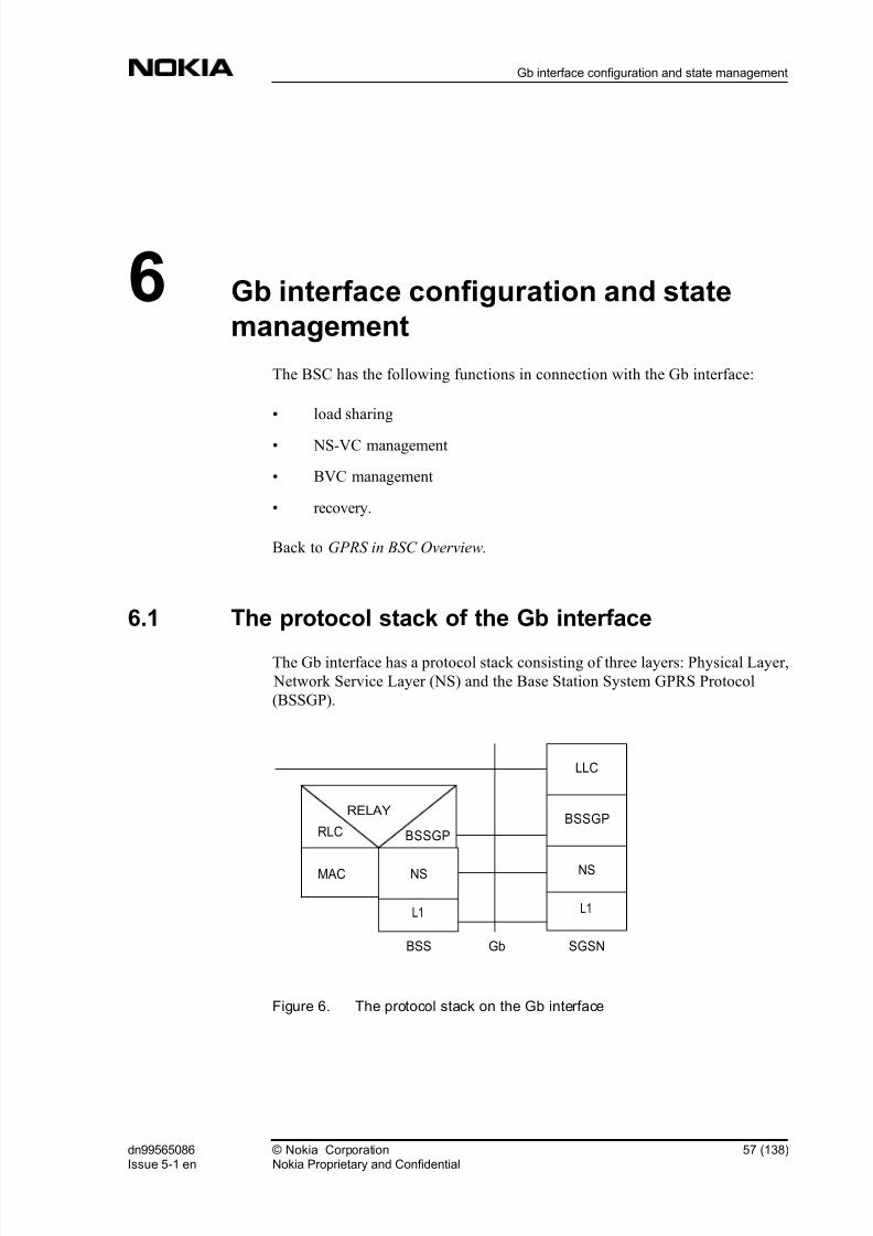
8/2/2019 01 Gprs Inokia
http://slidepdf.com/reader/full/01-gprs-inokia 57/138
6 Gb interface configuration and state
management
The BSC has the following functions in connection with the Gb interface:
" load sharing
" NS-VC management
" BVC management
" recovery.
Back to GPRS in BSC Overview.
6.1 The protocol stack of the Gb interface
The Gb interface has a protocol stack consisting of three layers: Physical Layer,
Network Service Layer (NS) and the Base Station System GPRS Protocol
(BSSGP).
Figure 6. The protocol stack on the Gb interface
SGSNGbBSS
L1
NS
BSSGP
RELAY
RLC
MAC
LLC
BSSGP
NS
L1
dn99565086Issue 5-1 en
© Nokia CorporationNokia Proprietary and Confidential
57 (138)
Gb interface configuration and state management

8/2/2019 01 Gprs Inokia
http://slidepdf.com/reader/full/01-gprs-inokia 58/138
Network Service Virtual Connection (NS-VC)
NS-VCs are end-to-end virtual connections between the BSS and SGSN. The
physical link in the Gb interface is the Frame Relay Bearer channel.
An NS-VC is the permanent virtual connection (PVC) and corresponds to the
Frame Relay DLCI (Data Link Connection Identifier) together with the Bearer
channel identifier. Each NS-VC is identified by means of an NS-VCI (Network
Service Virtual Connection Identifier).
Network Service Virtual Connection Group (NSE)
NSE identifies a group of NS-VCs in the BSC. The NSEI is used by the BSC to
determine the NS-VC that provides service to a BSSGP Virtual connection (BVC
). One NSE is configured between two peer NSs. At each side of the Gb interface,
there is a one-to-one correspondence between a group of NS-VCs and an NSEI.The NSEI has an end-to-end significance across the Gb interface at NS level, but
only local significance at the BSSGP level. One NSE per PCU is supported and
within one NSE a maximum of four NS-VCs are supported.
BSSGP Virtual Connection (BVC)
BVCs are communication paths between peer NS user entities on the BSSGP
level. Each BVC is supported by one NSE and it is used to transport Network
Service Service Data Units (NS SDUs) between peer NS users.
Each BVC is identified by means of a BVCI which has end-to-end significance
across the Gb interface. Each BVC is unique between two peer NSs.
Within BSS the user identifies a cell uniquely by a BVCI. The BVCI value 0000
(hex) is used for signalling and the value 0001 (hex) is reserved for point-to-
multipoint (PTM). PTM is not supported. All other values can be used for cell
identifiers.
Link Selector Parameter (LSP)
All BSSGP UNITDATA PDUs related to an MS are passed to NS with the same
LSP. This preserves the order of BSSGP UNITDATA PDUs, since the LSP is
always mapped to the certain NS-VC. LSP has only local significance at each endof the Gb interface.
Permanent Virtual Connection (PVC)
See Network Service Virtual Connection (NS-VC) .
More information on Gb interface configuration and state management:
58 (138) © Nokia CorporationNokia Proprietary and Confidential
dn99565086Issue 5-1 en
GPRS in BSC

8/2/2019 01 Gprs Inokia
http://slidepdf.com/reader/full/01-gprs-inokia 59/138
Load sharing function
NS-VC management function
BVC management function
Recovery in restart and switchover
Back to GPRS in BSC Overview.
6.2 Load sharing function
The BSC's load sharing function distributes all uplink Network Service Service
Data Units (NS SDU s) among the unblocked NS-VCs within the NSE on the Gb
interface. The use of load sharing also provides the upper layer with seamless
service upon failure or user intervention by reorganising the SDU traffic between
the unblocked NS-VCs. When creating the NS-VC the operator gives a CIR
value (bit/s). Note that all NS-VC CIR values need to have the same value.
The reorganisation may disturb the order of transmitted SDUs. All NS SDUs to
be transmitted over the Gb interface towards the SGSN are passed from BSSGP
to NS along with the Link Selector Parameter (LSP ). For each BVC, NS SDUs
with the same LSP are sent on the same NS-VC, since the LSP is always mapped
to a certain NS-VC. Thus, the load sharing function guarantees that, for each
BVC, the order of all NS SDUs marked with the same LSP value is preserved.
The load sharing functions of the BSC and SGSN are independent. Therefore,
uplink and downlink NS SDUs may be transferred over different NS-VCs. SGSN
distributes downlink NS SDUs.
More information on Gb interface configuration and state management:
The protocol stack of the Gb interface
NS-VC management function
BVC management function
Recovery in restart and switchover
Back to GPRS in BSC Overview.
dn99565086Issue 5-1 en
© Nokia CorporationNokia Proprietary and Confidential
59 (138)
Gb interface configuration and state management

8/2/2019 01 Gprs Inokia
http://slidepdf.com/reader/full/01-gprs-inokia 60/138
6.3 NS-VC management function
The Network Service Virtual Connection (NS-VC) management function is
responsible for the blocking, unblocking, resetting, and testing of NS-VCs. NS-VC management procedures can be triggered by both the BSC and the SGSN.
Only one substate (BL-US, BL-SY or BL-RC) is valid at a time when an NS-VC
is blocked. The BL-US state overrides both the BL-SY and BL-RC states. The
BL-SY state overrides the BL-RC state. The BL-RC state does not override any
other blocking state, so it is only possible when the NS-VC is unblocked. An
exception is when the NS-VC is in the BL-SY state and SGSN initiates an NS-
RESET. Refer to NS-VC reset.
Table 1. NS-VC operational states
State Possible substates
Unblocked (WO-EX Available) BL-RC (unavailable by remote user)
Blocked BL-US (unavailable by useror BL-SY (unavailable by
system) or BL-RC (unavailable by remote user)
NS-VC blocking
When an NS-VC is unavailable for BSSGP traffic, the NS-VC is marked as blocked by the BSC and the peer NS is informed by means of the blocking
procedure.
The BSC blocks an NS-VC when:
" the user locks the NS-VC, thus making it unavailable for BSSGP traffic;
the cause sent to SGSN is "O & M intervention"; operational state is BL-
US
" an NS-VC test fails; the cause sent to SGSN is "Transit network failure";
operational state is BL-SY
" Frame Relay detects unavailability of a bearer or PVC; the cause sent to
SGSN is "Transit network failure"; operational state is BL-SY
During user block the BSC marks the NS-VC as user blocked, informs peer NSs,
and reorganises BSSGP traffic to use other unblocked NS-VCs of the NSE. User-
triggered blocking is started only when the PVC or the bearer is available,
otherwise the NS-VC is marked as user blocked and the block procedure is
skipped. The BSC cancels any pending NS-VC management procedure and
related alarm.
60 (138) © Nokia CorporationNokia Proprietary and Confidential
dn99565086Issue 5-1 en
GPRS in BSC

8/2/2019 01 Gprs Inokia
http://slidepdf.com/reader/full/01-gprs-inokia 61/138
After NS-VC test failure the NS-VC is marked as system blocked, the BSC raises
the alarm NETWORK SERVICE VIRTUAL CONNECTION TEST
PROCEDURE FAILED (3025 ) and blocks the NS-VC towards the SGSN
through any 'live' NS-VC within the NSE, blocked or unblocked. The BSC also
initiates the NS-VC reset procedure. BSSGP traffic is reorganized to use other
unblocked NS-VCs of the NSE. If the NS-VC is user blocked while reset is
attempted, the reset is stopped, the user block is accepted and the state of the NS-
VC is user blocked. The BSC cancels the NETWORK SERVICE VIRTUAL
CONNECTION TEST PROCEDURE FAILED (3025 ) alarm after the next
successful test procedure on the NS-VC. If the NS-VC is already user blocked,
the BSC does not change the NS-VC state, it sets no alarms, and sends no block
to the SGSN, but instead initiates the NS-VC reset procedure. After a successful
reset, the test procedure is continued. If the NS-VC reset procedure fails after all
the retries, no alarm is set.
After the BSC detects the unavailability of a PVC or a bearer, the related NS-VC(s) is marked as system blocked and the BSC blocks it towards the SGSN through
any 'live' NS-VC within the NSE, blocked or unblocked. The BSC sets the
NETWORK SERVICE VIRTUAL CONNECTION UNAVAILABLE (3020 )
alarm for the blocked NS-VC(s) and reorganises BSSGP traffic to use other
unblocked NS-VCs of the NSE. If the NS-VC(s) is already user blocked, when
the unavailability of a PVC or bearer is detected, the BSC does not change the
state of the NS-VC(s), does not set an alarm, and does not send a block to the
SGSN, but instead stops the NS-VC(s) test. If the NS-VC(s) is already system
blocked, the BSC actions are the same but it also stops a possible ongoing reset
procedure.
During an SGSN-initiated block, if the NS-VC is not user, system or remote
blocked, the BSC marks the NS-VC as remote blocked, reorganises BSSGP
traffic to use other unblocked NS-VCs of the NSE and sets the alarm NETWORK
SERVICE VIRTUAL CONNECTION UNAVAILABLE (3020 ). If the NS-VC is
user, system or remote blocked, then the BSC does not change the NS-VC state
and acknowledges the received block back to the SGSN.
In all the above cases, if the blocked NS-VC is the last one in the NSE, it means
that all BSSGP traffic to/from PCU-managed cells stops on the Gb interface, and
the BSC sends System Information messages to relevant cells indicating that
GPRS is disabled. The BSC sets the NETWORK SERVICE ENTITY
UNAVAILABLE (3019 ) alarm when PVC/bearers are unavailable, the SGSN
initiates the block, or related BVCs are implicitly blocked.
NS-VC unblocking
When the NS-VC becomes available again for BSSGP traffic, the peer NS is
informed by means of the unblocking procedure, after which the NS-VC is
marked as unblocked by the BSC.
dn99565086Issue 5-1 en
© Nokia CorporationNokia Proprietary and Confidential
61 (138)
Gb interface configuration and state management

8/2/2019 01 Gprs Inokia
http://slidepdf.com/reader/full/01-gprs-inokia 62/138
The BSC unblocks an NS-VC after:
" user unlocks the NS-VC thus making it available for BSSGP traffic.
" the system initiates a NS-VC reset, for example after a test failed NS-VC isreset or after a reset of a NS-VC whose bearer is resumed as available for
NS level.
During user unblock the BSC informs the peer NS and marks the NS-VC as
unblocked after receiving an acknowledgement from the peer NS. New BSSGP
traffic now uses this new NS link (refer to Load sharing function ). User triggered
unblocking starts only when the PVC or the bearer is available, otherwise the
BSC marks the NS-VC as system blocked and skips the unblock procedure. The
BSC sets the NETWORK SERVICE VIRTUAL CONNECTION UNBLOCK
PROCEDURE FAILED (3021 ) alarm and marks the NS-VC unblock as pending
until NS-VC unblock can be performed and the alarm is cancelled by the BSC.
During system unblock the BSC cancels the NETWORK SERVICE VIRTUAL
CONNECTION UNAVAILABLE (3020 ) alarm. The BSC does not start system
initiated unblock if the NS-VC is user blocked.
During SGSN initiated unblock, the BSC marks the NS-VC as unblocked and
cancels the NETWORK SERVICE VIRTUAL CONNECTION UNAVAILABLE
(3020 ) alarm if the NS-VC is not user or system blocked. If the NS-VC is user
blocked, then the BSC is not able to unblock the NS-VC. The NS-VC remains
user blocked and the BSC initiates the NS-VC blocking procedure by returning
an NS-BLOCK PDU to the SGSN with the cause "O & M intervention". This
NS-BLOCK PDU is sent on the NS-VC where the NS-UNBLOCK PDU was
received. If the NS-VC is system blocked with no BSC initiated unblock
procedure on, then the BSC is not able to unblock the NS-VC. The NS-VC
remains system blocked and the BSC initiates the NS-VC reset procedure by
returning an NS-RESET PDU to the SGSN with the cause "PDU not compatible
with the protocol state". If the NS-VC is system blocked with a BSC initiated
unblock procedure on, then the BSC acknowledges the received PDU back to the
SGSN and it is interpreted as an acknowledgement for the sent NS-UNBLOCK
PDU.
In all the above cases, if the unblocked NS-VC is the first one in the NSE, it
means that BSSGP traffic to/from PCU-managed cells can start again on the Gbinterface, and the BSC sends System Information messages to relevant cells
indicating that GPRS is enabled. The BSC triggers the BVC reset procedure for
signalling BVC and cell-specific BVCs, and cancels the NETWORK SERVICE
ENTITY UNAVAILABLE (3019 ) alarm in cases of system unblock and SGSN
initiated unblock.
For more information refer to BSC-SGSN Interface Specification, Network
Service Protocol (NS) .
62 (138) © Nokia CorporationNokia Proprietary and Confidential
dn99565086Issue 5-1 en
GPRS in BSC

8/2/2019 01 Gprs Inokia
http://slidepdf.com/reader/full/01-gprs-inokia 63/138
NS-VC reset
The NS-VC reset procedure is used to reset an NS-VC to a determined state
between peer NSs.
The BSC resets an NS-VC after:
" the user sets up a new or modifies an existing NS-VC or unlocks an NS-
VC; the cause sent to the SGSN is "O & M intervention"
" a system or BCSU restart; the cause sent to the SGSN is "Equipment
failure" (see BCSU (PCU) restart )
" a periodic NS-VC test fails; the cause sent to the SGSN is "Transit network
failure"
" Frame Relay detects an unavailability of a bearer; the cause sent to theSGSN is "Transit network failure".
During a reset triggered by user unblock, the BSC marks the NS-VC as system
blocked, informs the peer NS, and reorganises BSSGP traffic to use other
unblocked NS-VCs of the NSE. After a completed reset procedure, the BSC starts
a test procedure (periodic testing) and after successful testing unblocks the NS-
VC. The BSC starts a reset triggered by user unblock only when the PVC or the
bearer is available, otherwise it marks the NS-VC as system blocked, skips the
reset procedure, and sets the NETWORK SERVICE VIRTUAL CONNECTION
RESET PROCEDURE FAILED (3023 ) alarm. The BSC sets the NS-VC reset as
pending until the NS-VC reset can be performed and then cancels the alarm.
During an SGSN-initiated reset, the BSC marks the NS-VC as remote blocked
and sets the NETWORK SERVICE VIRTUAL CONNECTION
UNAVAILABLE (3020 ) alarm if the NS-VC is not user or remote blocked. If the
NS-VC is user or remote blocked, then the BSC does not change the state, but
acknowledges the received reset back to SGSN and initiates the test procedure. If
the NS-VC is system blocked, then the action depends on whether the NS-VC
reset is ongoing or not. If the NS-VC reset is ongoing, then the received NS-
RESET is interpreted as an acknowledgement and the BSC acknowledges it back
to the SGSN and initiates the test procedure. If the NS-VC reset is stopped, then
the BSC changes the NS-VC state to remote blocked (to get the NS-VC up during
SGSN initiated NS-VC unblock), acknowledges the received reset back to the
SGSN, and initiates the test procedure.
In all the above cases, if the blocked NS-VC is the last one in the NSE, it means
that all BSSGP traffic to/from PCU managed cells stops on the Gb interface, and
the BSC sends System Information messages to relevant cells indicating that
GPRS is disabled. The BSC sets the NETWORK SERVICE ENTITY
UNAVAILABLE (3019 ) alarm in a SGSN initiated reset and blocks the related
BVCs implicitly.
dn99565086Issue 5-1 en
© Nokia CorporationNokia Proprietary and Confidential
63 (138)
Gb interface configuration and state management

8/2/2019 01 Gprs Inokia
http://slidepdf.com/reader/full/01-gprs-inokia 64/138
For more information refer to BSC-SGSN Interface Specification, Network
Service Protocol (NS) .
NS-VC test
The NS-VC test procedure is used when the BSC checks that end-to-end
communication exists between peer NSs on a given NS-VC. The user can define
the test procedure with the PRFILE parameter TNS_TEST . When end-to-end
communication exists, the NS-VC is said to be "live", otherwise it is "dead". A
"dead" NS-VC cannot be in the unblocked state, instead it is always marked as
blocked and a reset procedure is initiated.
Both sides of the Gb interface may initiate the NS-VC test independently from
each other. This procedure is initiated after successful completion of the reset
procedure, and is then periodically repeated. The test procedure runs on
unblocked NS-VCs and also on user blocked and remote blocked NS-VCs, but not on system blocked NS-VCs, except after NS-VC reset. The test procedure is
stopped when the underlying bearer or PVC is unavailable.
For more information refer to BSC-SGSN Interface Specification, Network
Service Protocol (NS) .
More information on Gb interface configuration and state management:
The protocol stack of the Gb interface
Load sharing function
BVC management function
Recovery in restart and switchover
Back to GPRS in BSC Overview.
6.4 BVC management function
The BVC management function is responsible for the blocking, unblocking and
reset of BVCs. The BVC reset procedure can be triggered by both the BSC and
the SGSN, but BVC blocking and unblocking procedures can only be triggered
by the BSC.
64 (138) © Nokia CorporationNokia Proprietary and Confidential
dn99565086Issue 5-1 en
GPRS in BSC

8/2/2019 01 Gprs Inokia
http://slidepdf.com/reader/full/01-gprs-inokia 65/138
Table 2. BVC operational states
State Possible substate
Unblocked (WO-EX, available) BL-SY (unavailable by system)
BVC blocking and unblocking
BVC blocking is initiated by the BSC to remove a BVC from GPRS data use.
The BSC blocks a BVC after:
" a user disables GPRS in a cell, disables the last GPRS-supporting TRX in a cell, blocks the BCCH TRX in a cell, or deletes a BVC by disabling GPRS
in a cell; the cause sent to the SGSN is "O & M intervention"
" a user or system block of the last NS-VC of the NSE serving the BVC;
related BVCs are locally blocked by the BSC, no indication is sent to the
SGSN
" SGSN initiates a BVC-RESET procedure (if necessary); the cause sent to
the SGSN is "BVCI-blocked"
" a cell level fault, for example at the beginning of site reset, BTS reset or
TRX reset; the cause sent to the SGSN is "Equipment failure".
BVC unblocking is used only in an exceptional condition when the BSC receives
an unexpected BVC-BLOCK-ACK PDU relating to a BVC that is locally
unblocked. The BSC then unblocks the BVC with the BVC-UNBLOCK PDU.
For more information refer to BSC-SGSN Interface Specification, BSS GPRS
Protocol (BSSGP) .
BVC reset
A BVC reset is initiated by the BSC to bring GPRS data into use in a BVC. BVC
reset is used instead of BVC unblock because of the dynamic configuration of BVCs in the SGSN.
The BSC resets a BVC after:
dn99565086Issue 5-1 en
© Nokia CorporationNokia Proprietary and Confidential
65 (138)
Gb interface configuration and state management

8/2/2019 01 Gprs Inokia
http://slidepdf.com/reader/full/01-gprs-inokia 66/138
" the user enables GPRS in a cell, enables the first GPRS-supporting TRX in
a cell, deblocks the BCCH TRX in a cell, or creates a BVC by enabling
GPRS in a cell; the cause sent to the SGSN is "O & M intervention"
" a user or system unblock of the first NS-VC of the NSE serving the BVC(signalling BVC is reset first, then the rest); the cause sent to the SGSN is
"Network service transmission capacity modified from zero kbit/s to
greater than zero kbit/s"
" a cell restart, for example after site, BTS or TRX reset, when the restarted
object is working; the cause sent to the SGSN is "Equipment failure".
With the BVC reset the underlying network service must be available for use,
otherwise the BSC marks the BVC as unblocked in order to get the BVC up and
running when the NS-level becomes available again, skips the BVC reset
procedure, and sets the BSSGP VIRTUAL CONNECTION RESET
PROCEDURE FAILED (3031 ) alarm. The BSC cancels the alarm after the next
successful BVC block, unblock or reset.
For more information refer to BSC-SGSN Interface Specification, BSS GPRS
Protocol (BSSGP) .
More information on Gb interface configuration and state management:
The protocol stack of the Gb interface
Load sharing function
NS-VC management function
Recovery in restart and switchover
Back to GPRS in BSC Overview.
6.5 Recovery in restart and switchover
In a recovery situation the BCSU and PCU are always handled together as a pair.The diagnostics of the PCU is included in the diagnostics of the BCSU.
Diagnostics is run automatically, but the operator may also start the diagnostics
routine if needed.
66 (138) © Nokia CorporationNokia Proprietary and Confidential
dn99565086Issue 5-1 en
GPRS in BSC

8/2/2019 01 Gprs Inokia
http://slidepdf.com/reader/full/01-gprs-inokia 67/138
BCSU (PCU) restart
If the Gb interface uses Frame Relay, after user or system initiated BCSU (PCU)
restart, the BSC recreates the Gb interface on the restarted PCU right after Frame
Relay level set-up. The PCU starts Frame Relay level periodic polling towards
the SGSN. Spontaneous indications come from the SGSN to the BSC's PCU on
Frame Relay level about bearer channel availability for NS-VCs.
First all NS-VCs are created, then all BVCs are created after cell-specific block
indications. The PCU maintains only user blocked information of NS-VCs. The
NS-VCs which have received DLCIs from the network are reset when the bearer
channel is available. The PCU sets others as pending and raises the NETWORK
SERVICE VIRTUAL CONNECTION RESET PROCEDURE FAILED (3023 )
alarm for each NS-VC.
The reset procedure is completed when the PCU receives a suitable DLCI fromthe network, and cancels the alarm. The PCU then initiates the test procedure on
the successfully reset NS-VCs, and after successful tests unblocks all tested NS-
VCs, and resets the signalling BVC. After successful BVC reset the uplink
BSSGP data delivery is possible on that BVC. After an initial flow control
procedure for the BVCs, also downlink BSSGP data delivery is possible on that
BVC. Flow control is discussed more in GPRS radio connection control .
BCSU (PCU) switchover
If the Gb interface uses Frame Relay, after BCSU (PCU) switchover (either user
or system initiated), the BSC recreates the Gb interface on the target PCU right after Frame Relay level set-up. The Gb interface configuration is from the source
PCU and the setting up of the Gb interface is similar to what was described in the
section BCSU (PCU) restart.
The BSC does not send NS level blocks from the source PCU in order not to
interrupt the BVC configurations of the SGSN.
Forced BCSU (PCU) switchover
The operation in a forced BCSU (PCU) switchover is very similar to the
operation in a BCSU (PCU) restart. The PCU releases all PCU PCM connections
related to the restarted PCU. All GPRS data connections will drop after the PCUPCM connections are released.
After the switchover whether user or system initiated the BSC unblocks
TRXs and delivers new territory to the PCU.
dn99565086Issue 5-1 en
© Nokia CorporationNokia Proprietary and Confidential
67 (138)
Gb interface configuration and state management

8/2/2019 01 Gprs Inokia
http://slidepdf.com/reader/full/01-gprs-inokia 68/138
Controlled BCSU (PCU) switchover
A controlled BCSU (PCU) switchover is always a user action given with an
MML command. The user defines between which BCSUs the switchover is
made, and the system tries to make it. A controlled switchover may fail, for
example the system may cancel the switchover command if the execution could
lead to a situation where some of the circuit switched calls would drop. If the
switchover fails, the original working BCSU is restored back to the working state.
Note
Only GPRS data connections that are connected to the PCU are released.
In a successful switchover, the BSC moves the control of the working BCSU/
PCU pair to the spare BCSU/PCU pair as in the forced switchover, but data is
copied only from the working BCSU to the spare BCSU. Because GPRS data is
not copied to the PCU, the PCU sees the data as lost and thus releases all its PCU
PCM connections and unblocks its BTSs. The BSC resets the new spare PCU to
the working state, and defines its new GPRS territory.
If the switchover is cancelled for some reason, the original working PCU is
restored back to the working state, and the BSC resumes GPRS territory
updatings. The BSC allows new GPRS connection setups in the old working
PCU again. After an unsuccessful switchover the PCU uses the same GPRSterritory as it had before the switchover. At the end of the switchover the spare
PCU is restarted regardless of the switchover being successful or not.
More information on Gb interface configuration and state management:
The protocol stack of the Gb interface
Load sharing function
NS-VC management function
BVC management function
Back to GPRS in BSC Overview.
68 (138) © Nokia CorporationNokia Proprietary and Confidential
dn99565086Issue 5-1 en
GPRS in BSC
8/2/2019 01 Gprs Inokia
http://slidepdf.com/reader/full/01-gprs-inokia 69/138
7 Dynamic Abis
The increasing capacity demand of the services connected over EDGE sets new
demands for Abis interface transmission, as well. The Abis interface transmission
requirement varies a lot depending on the call type used. It is not sensible to
allocate fixed transmission capacity according to the highest possible data rate for
every traffic channel from the Abis interface but share common transmission
resources between several traffic channels.
The Dynamic Abis feature makes it possible to define common transmission
resources for EDGE capable TRXs situated in the same Abis ETPCM. This
common resource is called the Dynamic Abis Pool. There are fixedly allocated
transmission resources for Abis signalling links and traffic channels in Abis
ETPCM as before but extra transmission resources needed for EGPRS calls are
reserved from the dynamic Abis pool.
Refer to Dynamic Abis pool handling for operating instructions on how to handle
Dynamic Abis pools in the BSC.
Back to GPRS in BSC Overview.
7.1 Dynamic Abis Pool management
Dynamic Abis is an optional feature. However, the Dynamic Abis feature is a
mandatory feature to enable EGPRS support in the BSC and in the PCU. If
dynamic Abis is used, the operator must define the pool to be used by the TRX. It
must be located on the same PCM as TRXSIG and the fixed traffic timeslots.
Dynamic Abis usage cannot be modified later. If the operator wants to change the
TRX's usage of Dynamic Abis, the TRX must be deleted and created again. CS
calls are handled as before. Abis capacity is allocated fixedly.
dn99565086Issue 5-1 en
© Nokia CorporationNokia Proprietary and Confidential
69 (138)
Dynamic Abis

8/2/2019 01 Gprs Inokia
http://slidepdf.com/reader/full/01-gprs-inokia 70/138
Activating Dynamic Abis Pool for EGPRS use
The operator can allocate common transmission resources for EDGE capable
TRXs from the Abis ETPCM. This common resource is called the Dynamic Abis
Pool (DAP) and it is comprised of consecutive Abis ETPCM timeslots. There can
be several DAPs in one Abis ETPCM but normally only one is needed. The DAP
has to be created before the EDGE TRXs using the DAP are created to the Abis
ETPCM.
When a DAP is created, the BSC reserves the corresponding block of timeslots
from the PCUPCM. These PCUPCM circuits are needed when DAP circuits are
connected to EGPRS use. The BSC downgrades all packet switched traffic
channels from the PCU and then upgrades these same traffic channels to packet
switched use again. This short interruption ensures that the BSC can find a block
of free timeslots from the PCUPCM and to ensure optimised PCU DSP resource
usage for each DAP connected to the PCU. Refer to Creating dynamic Abis pool for operating instructions on how to handle Dynamic Abis pools in the BSC.
Dynamic Abis Pool modification
The operator can change the size of the Dynamic Abis Pool (DAP) by adding
Abis ETPCM timeslots to DAP, or by removing Abis ETPCM timeslots from
DAP. The integrity of the DAP is kept up in these operations. This means that
new Abis ETPCM timeslots are added to either upper or lower edge of the DAP
and Abis ETPCM timeslots are removed from either upper or lower edge of the
DAP.
When new Abis ETPCM timeslots are added to DAP, BSC reserves a
corresponding block of timeslots from PCUPCM. These PCUPCM circuits are
needed when DAP circuits are connected to EGPRS use. The BSC downgrades
all packet switched traffic channels from PCU and then upgrades these same
traffic channels to packet switched use again. This short interruption ensures that
the BSC can find a block of free timeslots from the PCUPCM and to ensure
optimised PCU DSP resource usage for each DAP connected to the PCU.
The operator can also change the controlling PCU of the DAP. When the DAP's
PCU is changed, the BSC downgrades all packet switched traffic channels from
both the old and the new PCU and then upgrades these same traffic channels to
packet switched use again. This short interruption ensures optimised PCU DSPresource usage for each DAP connected to those PCUs. If there are one or more
TRXs attached to that pool, the packet swithed channels of the segments of the
TRXs are upgraded to the new PCU. Refer to Modifying Dynamic Abis pool for
operating instructions on how to handle Dynamic Abis pools in the BSC.
70 (138) © Nokia CorporationNokia Proprietary and Confidential
dn99565086Issue 5-1 en
GPRS in BSC

8/2/2019 01 Gprs Inokia
http://slidepdf.com/reader/full/01-gprs-inokia 71/138
Dynamic Abis Pool deletion
The operator can delete Dynamic Abis Pool (DAP) when there are no TRXs
attached to it. The BSC releases all resources reserved for the DAP when it is
deleted. The BSC downgrades all packet switched traffic channels from the PCU
and then upgrades these same traffic channels to packet switched use again. This
short interruption ensures ensures optimised PCU DSP resource usage for each
other DAP connected to the PCU. Refer to Deleting Dynamic Abis pool for
operating instructions on how to handle Dynamic Abis pools in the BSC.
Dynamic Abis Pool circuit routings
Circuit routings are needed for Abis ETPCM circuits to utilise the Dynamic Abis
feature in BSC. The BSC makes these routings automatically when Dynamic
Abis Pool (DAP) is created, modified or deleted.
The BSC adds Abis ETPCM circuits to a circuit group named ETPCM at the
same time as the Abis ETPCM circuits are added to DAP. This prevents other use
of these Abis ETPCM circuits while they belong to the DAP. The ETPCM circuit
group is common for all DAP circuits.
The BSC has also own circuit group for every DAP. These DAP circuit groups
are named to DAPxxx, where xxx indicates Dynamic Abis Pool number with
three digits. The DAP circuit group is specially designed for Dynamic Abis and it
enables hunting and connection methods required by Dynamic Abis. The BSC
adds DAP circuits to the DAP circuit group as one bit wide circuits which are in
ascending order according to timeslots and subtimeslot. The BSC changes statesof these circuits from BA to WO at the same time as the circuits are added to
circuit group.
Note
It is not allowed to make changes to DAP routings manually even if it is possible
with MML commands provided by the DX200 platform. Removing DAP
routings causes malfunction of the Dynamic Abis feature.
More information on Dynamic Abis:
EGPRS Dynamic Abis Pool connections
Capacity of Dynamic Abis
Error conditions in Dynamic Abis
dn99565086Issue 5-1 en
© Nokia CorporationNokia Proprietary and Confidential
71 (138)
Dynamic Abis
8/2/2019 01 Gprs Inokia
http://slidepdf.com/reader/full/01-gprs-inokia 72/138
Restrictions to Dynamic Abis
Back to GPRS in BSC Overview.
7.2 EGPRS Dynamic Abis Pool connections
The BSC connects Dynamic Abis Pool circuits to EGPRS use. The DAP area
connected to EGPRS use is called the EGPRS Dynamic Abis Pool (EDAP). The
procedure where DAP circuits are connected to EGPRS use is called the EDAP
upgrade procedure and the procedure where DAP circuits are removed from
EGPRS use is called the EDAP downgrade procedure. If GPRS service is
provided with an EDGE TRX, EDAP circuits may also be used for GPRS. In
EDAP upgrade and downgrade the BSC downgrades all packet switched traffic
channels from the PCU and then upgrades these same traffic channels to packet switched use again. This short interruption ensures optimised PCU DSP resource
usage for each DAP connected to the PCU.
EGPRS Dynamic Abis Pool upgrade
The BSC performs the EDAP upgrade procedure when:
1. the DAP is created
2. new circuits are added to the DAP
3. the PCU controlling the DAP is restarted
There are two phases in the EDAP upgrade procedure. In the first phase the BSC
makes connections between Abis ETPCM circuits and PCUPCM circuits. In the
second phase the BSC attaches DAP circuits to EDAP by informing the PCU
about mappings between the Abis ETPCM circuits and the PCUPCM circuits.
The BSC connects DAP circuits to EDAP starting from the last circuit and then
connecting the next circuit from the side of previous circuit as long as there are
circuits configured to EGPRS use. EDAP is always comprised of consecutive
DAP circuits. In S10 all the circuits belonging to the DAP are connected to the
EDAP.
EGPRS Dynamic Abis Pool downgrade
The BSC starts the EDAP downgrade procedure when:
1. the DAP is deleted
2. circuits are removed from the DAP
72 (138) © Nokia CorporationNokia Proprietary and Confidential
dn99565086Issue 5-1 en
GPRS in BSC

8/2/2019 01 Gprs Inokia
http://slidepdf.com/reader/full/01-gprs-inokia 73/138
There are two phases in the EDAP downgrade procedure. In the first phase the
BSC detaches DAP circuits from the EDAP by informing the PCU about changed
mappings between Abis ETPCM circuits and PCUPCM circuits. In the second
phase the BSC releases connections between the Abis ETPCM circuits and the
PCUPCM circuits.
BCSU (PCU) restart
When the BCSU is restarted the BSC releases all EDAP connections related to
the BCSU. After the PCU becomes operational again, the BSC runs an upgrade
procedure for each EDAP controlled by the PCU. The PCU shares the DSP
resources optimally for all the EDAPs when the BCSU (PCU) is restarted.
BCSU (PCU) switchover
If a switchover is made for the BCSU, the BSC releases all EDAP connectionsrelated to the old BCSU and then starts an upgrade procedure to recover the
EDAP connections in the new BCSU. The PCU shares the DSP resources
optimally for all the EDAPs in BCSU (PCU) switchover.
More information on Dynamic Abis:
EGPRS Dynamic Abis Pool connections
Capacity of Dynamic Abis
Error conditions in Dynamic Abis
Restrictions to Dynamic Abis
Back to GPRS in BSC Overview.
7.3 Capacity of Dynamic Abis
The capacity of a specific EDAP depends on the total count of EDAPs in the
PCU, on the EDAP size, on the number of EDGE TRXs and EGPRS channels/
PDCHs connected to the EDAP, and on the modulation and coding schemes
(MCS) used in data transmission. The MCSs that are used are selected by the
PCU based on the radio link quality measurements and Link Adaption
algorithms. Operator parameters for initial MCSs are also taken into account
when selecting an MCS for data transmission. However, Dynamic Abis capacity
(EDAP size and available PCU DSP resources) also affects MCS usage and due
to this, Dynamic Abis and PCU capacity limitations are also taken into account in
MCS selection.
dn99565086Issue 5-1 en
© Nokia CorporationNokia Proprietary and Confidential
73 (138)
Dynamic Abis

8/2/2019 01 Gprs Inokia
http://slidepdf.com/reader/full/01-gprs-inokia 74/138
Dynamic Abis counters monitor EDAP usage and Dynamic Abis limitations to
TBF scheduling in the EGPRS territory. The following actions may have to be
considered if the Dynamic Abis counters indicate problems in Dynamic Abis
usage:
" increasing EDAP size
" decreasing the number of EDGE TRXs and/or EGPRS channels attached
to EDAP
" sharing the load between PCUs (moving an EDAP(s) and/or (E)GPRS
channels from one PCU to another)
" decreasing the initial CS/MCS for TBFs, in DL and/or UL direction
GPRS TBF
In the BSC there are separate territories for GPRS and EGPRS. In onther words,
GPRS traffic primarily uses non-EDGE TRXs and EGPRS traffic uses EDGE
TRXs. In GPRS load situations or when a GPRS territory does not exist, it is
possible that GPRS traffic (GPRS TBFs) uses EGPRS capacity from the EGPRS
territory. Nokia supports only coding schemes CS-1 and CS-2 in standard GPRS
service. When a GPRS TBF is via GPRS territory (via a non-EDGE TRX), the
CS-2 coding scheme needs only 16 kbit/s from Abis. When a GPRS TBF is via
EGPRS territory (via an EDGE TRX), the CS-2 coding scheme needs a 16 kbit/s
master Abis channel and one 16 kbit/s slave channel from the EDAP. This is
because the EDGE TRX uses different TRAU formats and synchronization
schemes. This means that master Abis channels and EDAP resources are only
used by the EGPRS territory. The EDAP is not used by the GPRS territory.
In case a 16 kbit/s slave channel for a GPRS TBF cannot be found, for example
due to the EDAP load situation, CS-2 cannot be used. In the UL direction, the
MS's transmission turn may have to be rejected. In the DL direction, CS-1 may be
used instead of CS-2 in certain cases.
Otherwise GPRS release 1 procedures apply for GPRS.
EGPRS TBF
The GPRS RR procedures apply in EGPRS also. The difference comes from theEGPRS's need for more than 16 kbit/s Abis channels. The master Abis channel is
always linked to a PDTCH . The rest of the required Abis transmission is
allocated from the EDAP in 16-64 kbit/s blocks, depending on the coding scheme
(MCS) used. The Dynamic Abis resource information and coding scheme is told
to the BTS by inband signalling of the EGPRS Abis L1 in the PCU master data
74 (138) © Nokia CorporationNokia Proprietary and Confidential
dn99565086Issue 5-1 en
GPRS in BSC
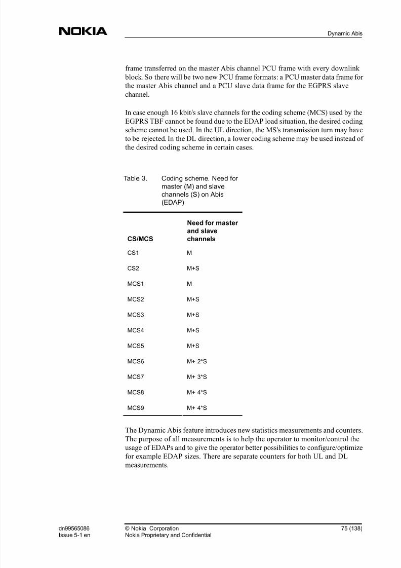
8/2/2019 01 Gprs Inokia
http://slidepdf.com/reader/full/01-gprs-inokia 75/138
frame transferred on the master Abis channel PCU frame with every downlink
block. So there will be two new PCU frame formats: a PCU master data frame for
the master Abis channel and a PCU slave data frame for the EGPRS slave
channel.
In case enough 16 kbit/s slave channels for the coding scheme (MCS) used by the
EGPRS TBF cannot be found due to the EDAP load situation, the desired coding
scheme cannot be used. In the UL direction, the MS's transmission turn may have
to be rejected. In the DL direction, a lower coding scheme may be used instead of
the desired coding scheme in certain cases.
Table 3. Coding scheme. Need for
master (M) and slave
channels (S) on Abis
(EDAP)
CS/MCS
Need for master
and slave
channels
CS1 M
CS2 M+S
MCS1 M
MCS2 M+S
MCS3 M+S
MCS4 M+S
MCS5 M+S
MCS6 M+ 2*S
MCS7 M+ 3*S
MCS8 M+ 4*S
MCS9 M+ 4*S
The Dynamic Abis feature introduces new statistics measurements and counters.
The purpose of all measurements is to help the operator to monitor/control the
usage of EDAPs and to give the operator better possibilities to configure/optimize
for example EDAP sizes. There are separate counters for both UL and DL
measurements.
dn99565086Issue 5-1 en
© Nokia CorporationNokia Proprietary and Confidential
75 (138)
Dynamic Abis

8/2/2019 01 Gprs Inokia
http://slidepdf.com/reader/full/01-gprs-inokia 76/138
Note
However, EDAP size is the same for both DL and UL directions, so it is not
possible to set different EDAP sizes for DL and UL directions.
For further information on statistics related to Dynamic Abis, see BSC Counters:
Dynamic Abis Measurement .
More information on Dynamic Abis:
Dynamic Abis Pool management
EGPRS Dynamic Abis Pool connections
Error conditions in Dynamic Abis
Restrictions to Dynamic Abis
Back to GPRS in BSC Overview.
7.4 Error conditions in Dynamic Abis
If the BSC cannot connect one DAP circuit to EDAP because of connection
failure, the BSC sets the alarm EGPRS DYNAMIC ABIS POOL FAILURE
(3068 ) and then attaches all successfully connected DAP circuits to EDAP.
The BSC sets the alarm EGPRS DYNAMIC ABIS POOL FAILURE (3068 ) if
an EDAP configuration update or an EDAP modification to PCU fails.
PCU capacity (for example, PCU DSP resource load for on-going EGPRS calls
using EDAP resources) may start limiting the EGPRS and GPRS RR procedures.
It is possible that new (E)GPRS TCHs cannot be added to the PCU.
If the BSC cannot attach DAP circuits to EDAP, the BSC sets the alarm EGPRS
DYNAMIC ABIS POOL FAILURE (3068 ).
More information on Dynamic Abis:
Dynamic Abis Pool management
EGPRS Dynamic Abis Pool connections
76 (138) © Nokia CorporationNokia Proprietary and Confidential
dn99565086Issue 5-1 en
GPRS in BSC
8/2/2019 01 Gprs Inokia
http://slidepdf.com/reader/full/01-gprs-inokia 77/138
Capacity of Dynamic Abis
Restrictions to Dynamic Abis
Back to GPRS in BSC Overview.
7.5 Restrictions to Dynamic Abis
Only Nokia UltraSite EDGE BTSs and Nokia MetroSite EDGE BTSs are able to
use Dynamic Abis allocation. Furthermore, only EDGE capable TRXs (EDGE
TRX) are capable of using shared EGPRS Dynamic Abis Pool (EDAP) resources.
Internal PCU restrictions:
" A PCU has 16 DSP cores. One DSP core can handle only one EDAP, but
one EDAP can be shared by several DSP cores. The maximum number of
EDAPs per PCU is 16.
" One DSP core can handle 0&20 channels (16 kbit/s) including active
EDAP channels, EGPRS channels, GPRS channels and PBCCH/
PCCCHs. The maximum number of 16 kbit/s channels per PCU is 256.
" All EGPRS channels of one EDGE TRX must be handled in the DSP core
that handles the related EDAP. If the EDAP is handled by several DSP
cores, the EGPRS channels of one EDGE TRX can be divided to several
DSP cores.
PCUPCM allocation restrictions:
" one EDAP cannot be divided to separate PCUPCMs
" Every EDGE TRX must have one synchronization master channel
(SMCH). SMCHs are allocated from the beginning of PCUPCM 0 and
they are usually allocated to a different PCUPCM TSL than other EGPRS
channels in the same TRX.
" One PCUPCM TSL (64 kbit/s = 4 x 16 kbit/s subTSLs) must be handled in
one DSP core.
A PCU shares DSP resources optimally for EDAPs when a new dynamic Abis
pool is created or an existing pool is deleted or modified. DSP resources are also
shared after BCSU restart or switchover. A PCU shares all (working) DSP cores
between all EDAP's connected to the PCU by using a PCU internal algorithm.
PCU DSP resources for an individual EDAP depends on the total number of
EDAPs for the PCU and on EDAP-specific properties (EDAP size and attached
dn99565086Issue 5-1 en
© Nokia CorporationNokia Proprietary and Confidential
77 (138)
Dynamic Abis

8/2/2019 01 Gprs Inokia
http://slidepdf.com/reader/full/01-gprs-inokia 78/138
default EGPRS channel count). Because the following formulas use the EDAP-
specific default EGPRS channel count, BCSU switchover is recommended when
the default EGPRS channel count is changed, in order to maintain optimal PCU
DSP resource sharing for EDAPs.
First the PCU calculates the ideal DSP core count for each EDAP:
, where
"EDAPsizeIn16kbit/sChannels is EDAP size in 16 kbit/s PCM subTSLs
" DefaultEGPRSChannels is the sum of default EGPRS channels of all the
TRXs (BTSs) attached to the EDAP
" 20 is the 16kbit/s channel handling capacity of a single PCU DSP core
The ideal DSP core count is rounded upwards.
For each EDAP, the PCU also calculates the EDAP DSP load based on the ideal
DSP core count for that EDAP:
If the sum of ideal DSP core counts for all EDAPs in the PCU differs from the
available DSP core count, the PCU adjusts DSP resources for each EDAP
according to the available DSP core count. If the sum of ideal DSP core counts
for all EDAPs in the PCU is less than the available DSP core count, then the extra
DSP cores are allocated to the EDAPs, starting from the EDAP with the highest
DSP EDAP load. If the sum of ideal DSP core counts for all EDAPs in the PCU
is more than the available DSP core count, then the PCU decreases the DSP corecount for the EDAPs that have the lowest DSP EDAP loads until the sum of
allocated DSP core counts equals the available DSP cores. However, each EDAP
gets at least one DSP core.
PCU DSP resources assigned to an EDAP may limit the usage of EDAP
resources and PCU capacity for new (E)GPRS channels.
Some possible but bad configuration examples:
IdealDSPcoreCountForEDAP=EDAPsizeIn16kbit/sChannels + DefaultEGPRSchannels
20
DSP_EDAPload= EDAPsizeIn16kbit/sChannels + DefaultEGPRSchannels
IdealDSPcoreCountForEDAP
78 (138) © Nokia CorporationNokia Proprietary and Confidential
dn99565086Issue 5-1 en
GPRS in BSC

8/2/2019 01 Gprs Inokia
http://slidepdf.com/reader/full/01-gprs-inokia 79/138
" One EDAP containing 12 TSLs and 15 EDAPs containing 2 TSLs each are
configured to one PCU. The first EDAP is handled in one DSP core, and
the EDAP has 48 channels. Only 16 EDAP channels of the first EDAP can
be used by 4 EGPRS channels.
" 16 EDAPs that each contain 3 TSLs are configured to a PCU. The TRXs
that are connected to one EDAP have 20 default GPRS channels (total
count). No single EDAP channel can be used and only MCS 1 or CS 1
traffic is possible in the TRXs.
Warning
WARNING: One EDAP resource should not be shared between several BCF
cabinets. It may damage the TRX or DTRU hardware if the operator tries to
share EDAP between several cabinets.
More information on Dynamic Abis:
Dynamic Abis Pool management
EGPRS Dynamic Abis Pool connections
Capacity of Dynamic Abis
Error conditions in Dynamic Abis
Back to GPRS in BSC Overview.
dn99565086Issue 5-1 en
© Nokia CorporationNokia Proprietary and Confidential
79 (138)
Dynamic Abis

8/2/2019 01 Gprs Inokia
http://slidepdf.com/reader/full/01-gprs-inokia 80/138
80 (138) © Nokia CorporationNokia Proprietary and Confidential
dn99565086Issue 5-1 en
GPRS in BSC

8/2/2019 01 Gprs Inokia
http://slidepdf.com/reader/full/01-gprs-inokia 81/138
8 Radio resource management
Channel allocation for GPRS data users is a two-phase procedure in the BSC.
In the first phase of the GPRS channel allocation the BSC defines the territory for
GPRS, which means selecting the radio time slots that the BSC will use primarily
for packet data traffic and therefore avoid in traffic channel allocation for circuit
switched services. The second phase includes the PCU activity during which thedifferent GPRS channels are assigned for GPRS TBFs within the radio time slots
of the GPRS territory.
The radio resource management function that allocates traffic channels for the
circuit switched calls is also responsible for the territory management and the
resource share between the circuit switched services and GPRS. The PCU has its
own radio channel allocation that takes care of allocating channels for GPRS
TBFs. Up to seven uplink GPRS TBFs can share the resources of a single radio
time slot. The uplink and downlink schedulings are independent of each other,
and for downlink up to sixteen GPRS TBFs can share the resources of a single
radio time slot.
First the operator has to activate the GPRS feature in the BSC with the cell-
specific parameter GPRS enable (GENA) and define which TRXs are capable
of GPRS with the parameter GPRS enabled TRX (GTRX) . To activate the
EGPRS feature, the operator uses the BTS-specific parameter EGPRS enable
(EGENA) . The BTS can contain both EDGE-capable and non-EDGE-capable
TRXs (HW), if GPRS is disabled in the non-EDGE-capable TRXs. The operator
needs to define which TRXs are capable of EGPRS with the parameter GPRS
enabled TRX (GTRX) .
Only after the BSC has an update on the BTS parameters and other parameters
indicating GPRS usage, does it count the number of default and dedicated GPRS
time slots in the BTS and selects a TRX where it starts to establish the GPRS
territory.
The BSC can upgrade or downgrade the number of radio resources allocated for
GPRS use according to the varying needs of the circuit switched and GPRS
traffic. These procedures are also explained in detail below.
Back to GPRS in BSC Overview.
dn99565086Issue 5-1 en
© Nokia CorporationNokia Proprietary and Confidential
81 (138)
Radio resource management

8/2/2019 01 Gprs Inokia
http://slidepdf.com/reader/full/01-gprs-inokia 82/138
8.1 Territory method
The territory method is the same for GPRS and EGPRS.
The BSC divides radio resources semipermanently between circuit switched
services and GPRS, thus forming two territories. The PCU uses the GPRS
territory resources. The initial territories are formed on a BTS-to-BTS basis
according to the operator-defined parameters. The BSC can later broaden the
GPRS territory based on the actual need and according to the requests of the
PCU.
The circuit switched services have priority over GPRS in channel allocation
within common resources. GPRS releases its resources as soon as they are needed
for circuit switched traffic.
Within a cell, all the Full Rate and Dual Rate traffic channels are GPRS capable.
GPRS capacity can be divided into three types:
" default GPRS capacity
" dedicated GPRS capacity
" additional GPRS capacity.
GPRS has a predefined set of resources which it can utilise when the circuit
switched load allows. This is referred to as the default GPRS capacity. Part of
these default traffic channels can be reserved solely for GPRS and this meansthey are blocked altogether from circuit switched use. This is referred to as the
dedicated GPRS capacity. The user can modify these two capacities by using the
respective parameters default GPRS capacity (CDEF) and dedicated
GPRS capacity (CDED) .
Additional GPRS capacity is referred to with radio time slots that are above and
beyond the default GPRS capacity and that the BSC has allocated for GPRS use
according to the requests of the PCU. GPRS territory size can be restricted by the
user-modifiable parameter max GPRS capacity (CMAX) . There is a GPRS
territory update guard time defining how often the PCU can request new radio
time slots for GPRS use.
82 (138) © Nokia CorporationNokia Proprietary and Confidential
dn99565086Issue 5-1 en
GPRS in BSC

8/2/2019 01 Gprs Inokia
http://slidepdf.com/reader/full/01-gprs-inokia 83/138
Figure 7. Territory method in BSC
The BSC calculates these defined resources from percentages to concrete
numbers of radio time slots based on the number of traffic channel radio time
slots (both blocked and working) capable of Full Rate traffic in the TRXs with
GPRS enabled (set with the parameter GPRS enabled TRX (GTRX) ). The
super reuse TRXs in the Intelligent Underlay Overlay feature and the extended
area TRXs in the Extended Range Cell feature are never included as available
resources in the GPRS territory calculation. The calculation is as follows:
" the product of default GPRS capacity (CDEF) parameter and the
number of radio time slots is rounded down to a whole number.
" if default GPRS capacity (CDEF) parameter value is > 0 but the
rounded product equals 0, then the territory size 1 is used
" default GPRS capacity (CDEF) parameter minimum value is 1.
" max GPRS capacity (CMAX) parameter minimum value is 1 (range 1
100%).
The BSC starts to create the GPRS territory by first selecting the most suitableTRXs in the BTS according to its GPRS capability, TRX type, TRX
configuration, and the actual traffic situation in the TRX.
The prefer BCCH frequency GPRS (BFG) parameter indicates if the
BCCH-TRX is the first or the last choice for the GPRS territory or if it is handled
equally with non-BCCH-TRXs. This is defined together with the circuit switched
related parameter TRX priority in TCH allocation (TRP) . The
parameter TRX priority in TCH allocation (TRP) first indicates
TRX 1
TRX 2
BCCH
Default
GPRS Capacity
DedicatedGPRS
Capacity
AdditionalGPRS
Capacity
Territory border moves based onCircuit Switched and GPRS traffic load
GPRSTerritory
CircuitSwitched
Territory
MaxGPRS
Capacity
dn99565086Issue 5-1 en
© Nokia CorporationNokia Proprietary and Confidential
83 (138)
Radio resource management
8/2/2019 01 Gprs Inokia
http://slidepdf.com/reader/full/01-gprs-inokia 84/138
whether a preference between BCCH and non-BCCH TRXs for circuit switched
traffic is made and prefer BCCH frequency GPRS (BFG) further indicates
if the same or the opposite prioritisation as for circuit switched traffic is applied in
establishing the GPRS territory.
The best candidate for GPRS territory according to the traffic load is the TCH
TRX that holds the most idle successive TCH/F time slots counted from the end
of the TRX (time slot 7). The GPRS time slots are always allocated from TSL7
towards TSL0 per TRX. The TRX containing permanent TCH/F time slots is
preferred to one with Dual Rate time slots to avoid wasting Half Rate capability
in the GPRS territory. TRXs with permanent TCH/H time slots or multislot
HSCSD calls are also avoided, if possible.
One TSL of an EDGE TRX works as a synchronisation master channel for the
other EGPRS channels on the EGPRS territory. GPRS/EGPRS traffic is not
possible in an EDGE capable TRX without a synchronisation master channel.The synchronisation master channel has to be part of the EGPRS territory or, in
case the PBCCH/PCCCH channel is allocated to an EDGE TRX, it acts as a
synchronisation master channel for the EGPRS channels of the BCCH TRX.
Having defined the GPRS capacity share and having selected the best TRX for
GPRS, the BSC next begins a GPRS territory upgrade procedure where it
allocates the selected radio time slots of the TRX for GPRS use and informs the
PCU.
GPRS territory upgrade
The BSC uses a GPRS territory upgrade procedure to allocate part of the
resources for GPRS use. The BSC starts the GPRS territory upgrade procedure
when the user enables GPRS in a BTS.
The number of time slots given for GPRS use is defined by the operator with the
parameters dedicated GPRS capacity (CDED) , default GPRS
capacity (CDEF) and max GPRS capacity . All the defined time slots
cannot necessarily be delivered immediately due to the circuit switched traffic
load of the BTS. However, the BSC fulfils the defined GPRS capacity as soon as
possible. After the default capacity (which includes also the dedicated part) has
been delivered, the PCU can request more resources for a GPRS territory upgrade
based on the actual need caused by GPRS use.
Each GPRS territory upgrade concerns time slots of one TRX; thus an upgrade is
a TRX-specific procedure. The BSC performs upgrades of continuous sets of
successive time slots. Starting from the end of the first TRX in the GPRS
territory, the BSC includes in a GPRS territory upgrade the time slots according
to need and availability.
84 (138) © Nokia CorporationNokia Proprietary and Confidential
dn99565086Issue 5-1 en
GPRS in BSC

8/2/2019 01 Gprs Inokia
http://slidepdf.com/reader/full/01-gprs-inokia 85/138
If the GPRS territory cannot be extended to its full size due to a time slot being
occupied by circuit switched traffic, an intra cell handover is started. The aim of
the handover is to move the circuit switched call to another time slot and clear the
time slot for GPRS use (refer to the figure below). The BSC then continues with
the upgrading of the GPRS territory after the release of the source channel of the
handover. If the GPRS territory of a BTS needs more time slots than one TRX
can offer, the BSC selects a new TRX and starts to define the territory.
When the user enables GPRS in a cell, the BSC starts a handover to be able to
allocate dedicated GPRS channels, even if the defined margin of idle time slots is
not met but there is at least one time slot available.
The BSC starts a handover to move a non-transparent multislot HSCSD call, but
not for a transparent multislot HSCSD call. For a transparent HSCSD call, the
HSCSD time slots are left inside the GPRS territory, although not as actual GPRS
channels. The BSC extends the GPRS territory on the other side of the time slotsreserved for the transparent HSCSD call.
Figure 8. GPRS territory upgrade when a time slot is cleared for GPRS use
with an intra cell handover
Situations leading to the starting of a GPRS territory upgrade are related to
configuration and traffic channel resource changes. When the user adds GPRS
capable TRXs in a BTS, it results in an increase in the time slot share that should
be provided for GPRS traffic. The BSC starts the GPRS territory upgrade
procedure when:
= Circuit Switched territory
= GPRS territory
B S C C C C C
C
C
C C
C
C d d D D D
C C C C
C C C
C
GPRS territory upgrade
B = BCCH TSLS = SDCCH TSLC = Circuit Switched call
Default GPRS capacity (d)= 20%Dedicated GPRS capacity (D) = 10%
dn99565086Issue 5-1 en
© Nokia CorporationNokia Proprietary and Confidential
85 (138)
Radio resource management

8/2/2019 01 Gprs Inokia
http://slidepdf.com/reader/full/01-gprs-inokia 86/138
" the user enables GPRS in a cell
" the user or BSC unblocks a GPRS enabled TRX thus enabling a pending
GPRS territory upgrade
" the user or BSC unblocks a radio time slot inside the GPRS territory
enabling it to be included in the GPRS territory
" the BSC releases a circuit switched TCH/F causing the number of idle
resources in the BTS to increase above a margin that is required before
GPRS territory upgrade can be started
" the BSC releases a circuit switched TCH/F beside the GPRS territory
border (as a consequence of handover) so that the pending GPRS territory
upgrade can be performed
" the PCU requests a GPRS territory upgrade.
Other general conditions for a GPRS territory upgrade are:
" previous GPRS territory change in the BTS has been completed
" that there is a sufficient margin of idle TCH/Fs in the BTS
" that there are idle GPRS capable resources available in the BTS
" that there is available capacity in the PCU controlling the BTS.
The margin of idle TCH/Fs that is required as a condition for starting a GPRS
territory upgrade is defined by the BSC parameter free TSL for CS upgrade(CSU) . In fact, the parameter defines how many traffic channel radio time slots
have to be left free after the GPRS territory upgrade. When defining the margin, a
two-dimensional table is used. In the two-dimensional table the columns are for
different amounts of available resources (TRXs) in the BTS. The rows indicate a
selected time period (seconds) during which probability for an expected
downgrade is no more than 5%. The operator can modify the period with the BSC
parameter CSU . The default value for the period length is 4 seconds.
Table 4. Defining the margin of idle TCH/Fs
T-
R-
Xs 1 2 3 4 5 6 7 8 9 10 11 12 13 14 15 16
Ti-
m-
e0
0 0 0 0 0 0 0 0 0 0 0 0 0 0 0 0
1 0 1 1 1 2 2 2 2 2 2 3 3 3 3 3 3
86 (138) © Nokia CorporationNokia Proprietary and Confidential
dn99565086Issue 5-1 en
GPRS in BSC

8/2/2019 01 Gprs Inokia
http://slidepdf.com/reader/full/01-gprs-inokia 87/138
Table 4. Defining the margin of idle TCH/Fs (cont.)
T-
R-
Xs 1 2 3 4 5 6 7 8 9 10 11 12 13 14 15 16
2 1 1 2 2 2 3 3 3 3 4 4 4 4 5 5 5
3 1 1 2 3 3 3 4 4 4 5 5 6 6 6 6 6
4 1 2 2 3 4 4 4 5 5 6 6 6 7 7 7 7
5 1 2 3 3 4 5 5 5 6 6 7 7 7 8 8 8
6 1 2 3 4 4 5 5 6 6 7 7 8 8 8 9 9
7 1 2 3 4 5 5 6 7 7 7 8 8 9 9 9 9
8 1 3 4 4 5 6 6 7 7 7 8 9 9 9 9 9
9 1 3 4 5 5 6 7 7 8 8 9 9 9 9 9 9
10 2 3 4 5 6 7 7 8 8 8 9 9 9 9 9 9
The user can define and modify with the parameter GPRS territory update
guard time (GTUGT) the guard time, which the PCU has to wait between
successive requests for GPRS territory configuration updates. The BSC obeys
this guard time also when it performs GPRS territory upgrades to fulfil theoperator-defined default GPRS territory.
If the conditions required for a GPRS territory upgrade are not met at the time the
PCU requests a GPRS territory upgrade, the BSC simply does nothing but
updates related statistics. There are three reasons for a GPRS territory upgrade
request being rejected: lack of GPRS radio resources, circuit switched traffic load,
and the capacity limit of the PCU unit. In case the PCU asks for several time slots
in one request and only a part of the requested resources are available, a statistics
counter is updated.
In the GPRS territory upgrade, the BSC selects a free PCUDSP channel from thePCU and connects it to an Abis circuit. If an error occurs when connecting the
PCUDSP circuit to the Abis circuit, the BSC cancels the upgrade and saves
information on the detected fault and starts to avoid the PCUDSP circuit in
question. The BSC initiates a new GPRS territory upgrade during which another
free PCUDSP channel is selected.
If two successive connection failures of a PCUDSP circuit with different Abis
circuits occur, the BSC marks the PCUDSP channel as faulty and sets the alarm
FAULTY PCUPCM TIMESLOTS IN PCU (3073 ).
dn99565086Issue 5-1 en
© Nokia CorporationNokia Proprietary and Confidential
87 (138)
Radio resource management
8/2/2019 01 Gprs Inokia
http://slidepdf.com/reader/full/01-gprs-inokia 88/138
Additional GPRS territory upgrade
The need for additional GPRS channels is checked when a new TBF is
established or an existing TBF is terminated. The PCU will request additional
channels, if a GPRS territory contains less channels than could be allocated to a
mobile according to its multislot class, or if the average number of TBFs per TSL
is more than 1.5 after the allocation of the new TBF (average TBF/TSL>1.5).
These additional channels will be requested only if all GPRS default channels are
already in the GPRS territory.
The number of additional channels the PCU will request is the greater of the
following two numbers:
" The number of additional channels needed in the allocation according to
the MS's multislot class (this criterion is used only when the GPRS
territory contains fewer channels than the MS is capable of using), and
" The number of additional channels needed for the average number of
allocated TBFs per TSL to be 1(average TBF/TSL=1).
Examples:
1. The GPRS territory consists of one (default) channel and resources should
be allocated for a downlink TBF of a multislot class 4 mobile. The PCU
will first allocate one channel for the TBF and it will request for (at least) 2
more channels, as the mobile is capable of using 3 downlink channels.
When the PCU receives this additional capacity, the TBF will be
reallocated to utilise all channels.
2. The GPRS territory consists of three channels (one default and two
additional) and a mobile of multislot class 4 has a downlink TBF of three
timeslots (performing ftp for example). One of the additional channels is
taken into CS use, the territory is decreased to two channels, and the
downlink TBF is reallocated to these channels. When the previously
reserved channel is freed from the CS side, a territory upgrade would be
possible, but nothing happens (no upgrade of the territory), because the
system only checks for need for upgrade when a new TBF is established.
However, if the existing TBF is terminated and a new one is established or
if the concurrent uplink TBF is terminated the need and possibility of theterritory upgrade is re-evaluated.
GPRS territory downgrade
The BSC uses a GPRS territory downgrade procedure when it needs to reduce the
share of time slots in the GPRS territory, for example when there is an increase in
the circuit switched traffic load.
The BSC starts a GPRS territory downgrade procedure when
88 (138) © Nokia CorporationNokia Proprietary and Confidential
dn99565086Issue 5-1 en
GPRS in BSC

8/2/2019 01 Gprs Inokia
http://slidepdf.com/reader/full/01-gprs-inokia 89/138
" the user disables GPRS in a cell
" the user or BSC blocks the TRX that is carrying GPRS traffic
" the user or BSC blocks the time slot that is carrying GPRS traffic
" the user or BSC blocks circuit switched resources causing the number of
idle resources in the BTS to decrease below the required margin
" the BSC allocates a traffic channel for circuit switched use causing the
number of idle resources in the BTS to decrease below the required margin
" the PCU requests for a GPRS territory downgrade
If the user or the BSC blocks the time slot that is carrying the synchronisation
master channel, the BSC starts a (E)GPRS territory downgrade procedure for all
(E)GPRS channels connected to that TRX.
The PCU initiates a GPRS territory downgrade procedure for additional type
GPRS radio time slots. This means that the PCU has requested these time slots for
GPRS traffic in addition to the default capacity, but the need for additional time
slots has ceased. If the BSC cannot start a GPRS territory downgrade at the time
the PCU requests it, the PCU will have to request a downgrade again after the
territory update guard time has expired, if the need for the downgrade still exists.
The operator defines the margin of idle TCHs that the BSC tries to maintain free
in a BTS for the incoming circuit switched resource requests using the parameter
free TSL for CS downgrade (CSD) . If the number of idle TCH resources
in the circuit switched territory of the BTS decreases below the defined margin, a GPRS territory downgrade is started if possible. The definition of the margin
involves a two-dimensional table. One index of the table is the number of TRXs
in the BTS. Another index of the table is the needed amount of idle TCHs. Actual
table items are percentage values indicating probability for TCH availability
during a one-second downgrade opreration with the selected resource criterion.
Default probability 95% can be changed through the free TSL for CS
downgrade (CSD) parameter (CSD).
Table 5. Defining the margin of idle TCHs, %
T-
R-
Xs 1 2 3 4 5 6 7 8 9 10 11 12 13 14 15 16
T-
C-
H0
94 84 76 69 63 58 54 50 48 45 43 41 40 38 37 35
1 99 98 96 93 91 87 85 82 79 77 74 72 70 68 66 64
dn99565086Issue 5-1 en
© Nokia CorporationNokia Proprietary and Confidential
89 (138)
Radio resource management

8/2/2019 01 Gprs Inokia
http://slidepdf.com/reader/full/01-gprs-inokia 90/138
Table 5. Defining the margin of idle TCHs, % (cont.)
T-
R-
Xs 1 2 3 4 5 6 7 8 9 10 11 12 13 14 15 16
2 10-
0
99 99 99 98 97 96 94 93 92 90 89 87 86 84 83
3 10-
0
99 99 99 98 98 97 97 96 95 94 94 93
4 10-
0
99 99 99 99 99 98 98 98 97
5 10-
0
10-
0
99 99 99 99
6 10-
0
10-
0
10-
0
7 10-
0
10-
0
8 10-
0%
10-
0%
10-
0%
10-
0%
9 10-
0
100
Additional GPRS territory downgrade
Additional channels are taken into CS use whenever more channels are needed on
the CS side. The need for additional GPRS channels is always checked when an
existing TBF is terminated. The PCU will request the removal of additional
channels, if the average TBFs per TLS is less than 0.5(average TBF/TSL<0.5).
More information on Radio resource management:
Circuit switched traffic channel allocation in GPRS territory
BTS selection for packet traffic
Quality of service
Channel allocation and scheduling
Error situations in GPRS connection
90 (138) © Nokia CorporationNokia Proprietary and Confidential
dn99565086Issue 5-1 en
GPRS in BSC

8/2/2019 01 Gprs Inokia
http://slidepdf.com/reader/full/01-gprs-inokia 91/138
Back to GPRS in BSC Overview.
8.2 Circuit switched traffic channel allocation in GPRSterritory
The BSC maintains a safety margin of idle traffic channels for circuit switched
traffic by starting a GPRS territory downgrade when the number of free traffic
channels in the circuit switched territory of a BTS decreases below the limit
defined by the parameter free TSL for CS downgrade (CSD) . Depending
on the size of the margin and on the amount of traffic on the BTS, new circuit
switched traffic channel requests may come before the GPRS territory downgrade
procedure has been completed. During a sudden burst of traffic channel requests,
the BSC may not be able to maintain the margin with the GPRS territory
downgrade procedure and the circuit switched territory may run out of idle traffic
channels.
If the circuit switched territory becomes congested, the BSC can allocate a traffic
channel for circuit switched use in the GPRS territory if there is one not
dedicated for GPRS. The BSC first releases the channel in GPRS use from the
PCU and then activates it in the BTS for circuit switched use.
The BSC cannot allocate a traffic channel in the GPRS territory for circuit
switched use, if the radio time slot in question is involved in a GPRS territory
upgrade procedure that has not been completed yet. In this case the circuit
switched traffic channel request is put in queue to wait for the GPRS territoryupgrade to finish. This kind of queuing can be performed if the MSC allows it for
the request. Traffic channel queuing during GPRS territory upgrade does not
require the normal queuing to be in use in the target BTS. The use of the
parameter free TSL for CS upgrade (CSU) aims at avoiding collisions
between a GPRS territory upgrade and circuit switched requests.
Multislot traffic channel allocation for an HSCSD call within the GPRS territory
follows the same principles as for single slot requests. A non-transparent HSCSD
call is placed inside the GPRS territory only in the case of total congestion of the
CS territory. In that case the HSCSD call can have one or more TSLs depending
on the HSCSD parameters of the BTS in question. A transparent HSCSD call can be allocated partly over the GPRS territory so that traffic channels for the call are
allocated from both territories or the whole HSCSD call can be allocated over the
GPRS territory.
More information on Radio resource management:
Territory method
dn99565086Issue 5-1 en
© Nokia CorporationNokia Proprietary and Confidential
91 (138)
Radio resource management
8/2/2019 01 Gprs Inokia
http://slidepdf.com/reader/full/01-gprs-inokia 92/138
BTS selection for packet traffic
Quality of service
Channel allocation and scheduling
Error situation in GPRS connection
Back to GPRS in BSC Overview.
8.3 BTS selection for packet traffic
Channel allocation goes through all the following steps, in the order presented, in
every allocation and reallocation instance. After every step, the list of valid BTSs
is relayed to next step and the BTSs that did not meet the requirements are
discarded.
BTS selection in a segment without PBCCH/PCCCH
1. Mobile RAC (bands)
With RF hopping there has to be a packet territory in BCCH BTS or in a
non-hopping BTS on BCCH band.
2. Check maximum TBF/TSL3. Signal Level
" In case of initial allocation (DL signal level not known), DIRE is
used for ruling out some BTSs. BTS with NBL value greater than
DIRE is ruled out.
" Reallocation based on signal level is trickered by ( RX_level
(BCCH)-NBL<GPL )
" In reallocation between different valid BTSs, NBL is used for
comparing levels and ruling out BTSs. ( RX_level(BCCH)-
NBL>GPU )
" In reallocation case, if no BTS fullfilling ( RX_level(BCCH)- NBL>GPU ) is found, the old BTS is selected.
4. Mobile capability (GPRS /EGPRS )
5. Load (Penalty,Qos)
92 (138) © Nokia CorporationNokia Proprietary and Confidential
dn99565086Issue 5-1 en
GPRS in BSC

8/2/2019 01 Gprs Inokia
http://slidepdf.com/reader/full/01-gprs-inokia 93/138
BTS selection in a segment with PBCCH/PCCH
1. Mobile RAC (bands)
2. Check maximum TBF/TSL in BTS
3. Signal Level
" In case of initial allocation (DL signal level not known), DIRE is
used for ruling out some BTSs. BTS with NBL value greater than
DIRE is ruled out.
" Reallocation based on signal level is trickered by:( RX_level
(BCCH)-NBL<GPL )
" In reallocation between different valid BTSs, NBL is used for
comparing levels and ruling out BTSs. ( RX_level(BCCH)-
NBL>GPU )
" In reallocation case, if no BTS fullfilling ( RX_level(BCCH)-
NBL>GPU ) is found, the old BTS is selected.
4. Mobile capability (GPRS/EGPRS)
5. Load (Penalty,Qos)
In UL reallocation, the uplink RX level of the TBF in the serving BTS is
compared to GPL to check if the reallocation was triggered by a bad uplink RX
level (uplink RX level < GPL). If the reallocation was due to bad uplink RX
level, then the old serving BTS will be discarded in the very beginning.
More information on Radio resource management:
Territory method
Circuit switched traffic channel allocation in GPRS territory
Quality of service
Channel allocation and scheduling
Error situation in GPRS connection
Back to GPRS in BSC Overview.
dn99565086Issue 5-1 en
© Nokia CorporationNokia Proprietary and Confidential
93 (138)
Radio resource management

8/2/2019 01 Gprs Inokia
http://slidepdf.com/reader/full/01-gprs-inokia 94/138
8.4 Quality of Service
The concept of 'Priority Class' is introduced at system level. This is based on
combinations of GPRS Delay class and GPRS Precedence class values. Packetshaving higher 'Priority' are sent before those packets having lower 'Priority'.
ETSI specifications define QoS functionality which gives the possibility to
differentiate TBFs by delay, throughput and priority. Priority Based Scheduling
is introduced as a first step towards QoS. With Priority Based Scheduling the
operator can give users different priorities. Higher priority users will get better
service than lower priority users. There will be no extra blocking to any user, only
the experienced service quality changes.
The PCU receives the QoS information to be used in DL TBFs from the SGSN in
a DL unitdata PDU. In case of UL TBF, the MS informs its radio priority in a PACKET CHANNEL REQUEST (PCR) or a PACKET RESOURCE REQUEST
(PRR), and this is used for UL QoS.
In the UL direction, the PCU uses the radio priority received from the MS.
Exceptions to this rule are one phase access and single block requests; in these
cases the PCU always uses Best Effort priority.
The PCU receives the QoS profile information element in the DL unitdata. This
IE includes Precedence class information which indicates the priority of the PDU.
Each TBF allocated to a timeslot has a so-called latest (timeslot specific) service
time. In each scheduling round (performed every 20ms), the TBF with the lowest
service time is selected and given a turn to send a radio block (provided that no
control blocks have to be sent). Also, the latest service time of the selected TBF is
incremented by the scheduling step size of the TBF.
The sizes of the scheduling steps determine the handing out of radio resources: If
several TBFs have been allocated to a timeslot, then the higher the scheduling
step size of the TBF, the less often it is selected and given a turn.
In release 1 scheduling step sizes are set to the same constant value for all TBFs.
In the S10.5 release these depend on the priority class of the TBF. Each priority
class has its own scheduling step size which is operator adjustable.
Priorities are also taken into account in allocations of TBFs. The allocation
process tries to ensure that better priority TBFs do not gather into the same radio
timeslot.
Priority Based Scheduling in BSC is a standard feature and is always active in an
active PCU.
94 (138) © Nokia CorporationNokia Proprietary and Confidential
dn99565086Issue 5-1 en
GPRS in BSC

8/2/2019 01 Gprs Inokia
http://slidepdf.com/reader/full/01-gprs-inokia 95/138
To get more detailed information about QoS in Gb, see BSC-SGSN interface
description; BSS GPRS protocol (BSSGP).
More information on Radio resource management:
Territory method
Circuit switched traffic channel allocation in GPRS territory
BTS selection for packet traffic
Channel allocation and scheduling
Error situation in GPRS connection
Back to GPRS in BSC Overview.
8.5 Channel allocation and scheduling
GPRS channels are allocated according to the following rules:
" downlink and uplink are separate resources
" multiple mobiles can share one traffic channel, but the traffic channel is
dedicated to one MS at a time this is referred to as temporary GPRSconnection block flow or Temporary Block Flow (TBF ) meaning that
one MS is transmitting or receiving at a time; seven uplink and sixteen
downlink TBFs can share the resources of a single time slot; the uplink and
downlink scheduling are independent
" channels allocated to a TBF must be allocated from the same TRX
" those traffic channels which give the maximum possible (priority based)
capacity for the TBF are allocated within the limits of the multislot class of
the mobile; exceptions are TBFs for which only one channel is allocated.
Temporary Block Flow (TBF) is explained in GPRS radio connection control .
The PCU determines the number of traffic channels that are needed and counts
the best throughput for that number of traffic channels. When the load of traffic
channel combinations is equal they are first compared by QoS load of the
channel, then by capacity type (additional < default < dedicated) and then by the
Packet Associated Control Channel (PACCH ) load. The QoS load of a channel is
dn99565086Issue 5-1 en
© Nokia CorporationNokia Proprietary and Confidential
95 (138)
Radio resource management

8/2/2019 01 Gprs Inokia
http://slidepdf.com/reader/full/01-gprs-inokia 96/138
defined as a weighted sum of the TBFs in the channel. The weights used
correspond with the scheduling rate of the QoS class of TBFs in the channel. The
PACCH load is the number of TBFs using a certain TCH as PACCH. PACCH is
defined in more detail in GPRS radio connection control .
Higher priority TBFs will get more turns, therefore they will cause more load on
the channel.
Packet scheduling
Uplink and downlink scheduling are independent. The PCU can assign multiple
MSs to the same uplink traffic channels. ETSI specifications allow the scheduling
of uplink transmission turns to be done by three different Medium Access modes
(MAC ): dynamic allocation, extended dynamic allocation and fixed allocation.
The BSC releases from S9 on support dynamic allocation.
In Dynamic allocation, the BSC gives the MS a USF value for each assigned
traffic channel in the assignment message. The MS monitors the downlink Radio
Link Control (RLC) blocks on the traffic channels it has been assigned.
Whenever the MS finds the USF value in the downlink RLC block, it may send
an uplink RLC block in the corresponding uplink frame. The scheduling of the
RLC data block in each time slot is independent of other time slots. Radio Link
Control is defined in more detail in GPRS radio connection control .
Scheduling is based on a kind of weighted round robin method, which means that
a higher priority (QoS) Temporary Block Flow (TBF) gets a bigger share of the
PDTCHs allocated for it than a lower priority TBF. See Quality of service for more information on adjusting weight.
TBF allocation
After the BTS has been selected, QoS and TBF type are compared
simultaneously. Different QoS classes result in different penalties for load
comparing. Multiplexed and non-multiplexed TSLs are also prioritized by a
penalty value. Among multiplexed TSLs, QoS is the selecting criteria.
If there are both GPRS and EGPRS TBFs allocated in the same BTS, the PCU
tries to avoid allocating the GPRS and EGPRS TBFs into the same timeslots
because it would dramatically worsen the throughput of EGPRS TBFs.
Multiplexing, that is, allocating GPRS and EGPRS TBFs into the same timeslots
is avoided by the means of a channel allocator: when it is searching for a best
channel configuration for a TBF, it 'sees' a penalty in those channel combinations
that would increase multiplexing.
96 (138) © Nokia CorporationNokia Proprietary and Confidential
dn99565086Issue 5-1 en
GPRS in BSC

8/2/2019 01 Gprs Inokia
http://slidepdf.com/reader/full/01-gprs-inokia 97/138
If we would like to allocate a new EGPRS TBF into a TRX, the channel allocator
would see the TRX as follows: the timeslots where there are already some GPRS
TBFs allocated would not look very attractive for this allocation, because the
EGPRS TBF would not get a very good data rate in those timeslots but it would
increase multiplexing.
When optimum resources for a mobile are searched for from the GPRS territory,
both UL and DL resources are evaluated and the decision for the allocation is
made depending on the amount of effective resources received in both directions.
If a mobile is using only one direction (UL or DL), only the resources of the
direction used are evaluated. If the mobile being evaluated already has an existing
TBF in one direction and it requires resources from the other direction, the
evaluation of resources received is first done for the concurrent allocation and
then for different re-allocations and, if effective resources received in the
concurrent allocation are the same as with re-allocation, the concurrent allocation
is preferred. In the evaluation of the resources, dedicated and default territoryareas are preferred, so if similar resources are found from the additional and
default territory, resources from the default area will be allocated.
Examples:
1. The GPRS territory consists of three channels, and a MS of multislot class
4 has a downlink TBF of three timeslots (performing ftp for example) and
also uses an uplink TBF of one timeslot to acknowledge the received data
(Note: the UL TBF is not always present as it is not always needed). A
second mobile of multislot class 4 requests UL resources. These will be
allocated to it and the optimum resources are evaluated for the ULdirection only. As a result, the second MS will get its UL resource from a
channel that is not used by the first mobile.
TSL 0 1 2 3 4 5 6 7
DEF DEF DEF
UL MS1 MS2
DL MS1 MS1 MS1
dn99565086Issue 5-1 en
© Nokia CorporationNokia Proprietary and Confidential
97 (138)
Radio resource management

8/2/2019 01 Gprs Inokia
http://slidepdf.com/reader/full/01-gprs-inokia 98/138
2. Continuing from the previous example, downlink resources are needed for
the second mobile. Available resources are evaluated for both directions
and the allocation is made in such a way that optimum resources are used
in both directions. Now the allocation depends on the resource usage of
MS1 in both UL and DL directions.
a. A concurrent allocation for the DL TBF is made for MS2 if MS1 has
an UL TBF in use when the DL TBF of MS2 is allocated. The
concurrent allocation is made, because the reallocation does not
provide any better resources for MS2 in this phase.
TSL 0 1 2 3 4 5 6 7
DEF DEF DEF
UL MS1 MS2
DL MS1 MS1
MS2
MS1
MS2
As a result, MS1 has the resources of 3 effective timeslots (the total
sum of UL and DL resources) and MS2 has the resources of 2
effective timeslots. If MS2 had been allocated in the same way as
MS1 (with re-allocation), it would have resulted in both MSs having
only 2 effective timeslots (the total sum of UL and DL resources).
MS2 does not receive the maximum amount of timeslots in the DL
direction in this phase, but it will receive them later, when theterritory upgrade has been completed.
b. DL resources for MS2 are given with reallocation if MS1 does not
have a UL TBF in use when the DL TBF of MS2 is allocated. The
reallocation is made, because better resources are achieved with it.
TSL 0 1 2 3 4 5 6 7
DEF DEF DEF
UL MS2
DL MS1
MS2
MS1
MS2
MS1
MS2
In this allocation, MS1 has the resources of 1.5 effective timeslots
(the total sum of UL and DL resources) and MS2 has the resources
of 2.5 effective timeslots.
98 (138) © Nokia CorporationNokia Proprietary and Confidential
dn99565086Issue 5-1 en
GPRS in BSC
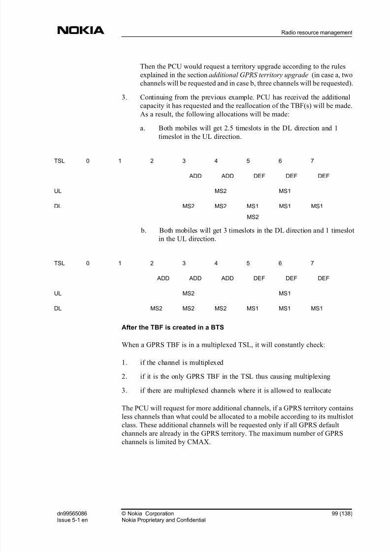
8/2/2019 01 Gprs Inokia
http://slidepdf.com/reader/full/01-gprs-inokia 99/138
Then the PCU would request a territory upgrade according to the rules
explained in the section additional GPRS territory upgrade (in case a, two
channels will be requested and in case b, three channels will be requested).
3. Continuing from the previous example. PCU has received the additionalcapacity it has requested and the reallocation of the TBF(s) will be made.
As a result, the following allocations will be made:
a. Both mobiles will get 2.5 timeslots in the DL direction and 1
timeslot in the UL direction.
TSL 0 1 2 3 4 5 6 7
ADD ADD DEF DEF DEF
UL MS2 MS1
DL MS2 MS2 MS1
MS2
MS1 MS1
b. Both mobiles will get 3 timeslots in the DL direction and 1 timeslot
in the UL direction.
TSL 0 1 2 3 4 5 6 7
ADD ADD ADD DEF DEF DEF
UL MS2 MS1
DL MS2 MS2 MS2 MS1 MS1 MS1
After the TBF is created in a BTS
When a GPRS TBF is in a multiplexed TSL, it will constantly check:
1. if the channel is multiplexed
2. if it is the only GPRS TBF in the TSL thus causing multiplexing
3. if there are multiplexed channels where it is allowed to reallocate
The PCU will request for more additional channels, if a GPRS territory contains
less channels than what could be allocated to a mobile according to its multislot
class. These additional channels will be requested only if all GPRS default
channels are already in the GPRS territory. The maximum number of GPRS
channels is limited by CMAX.
dn99565086Issue 5-1 en
© Nokia CorporationNokia Proprietary and Confidential
99 (138)
Radio resource management

8/2/2019 01 Gprs Inokia
http://slidepdf.com/reader/full/01-gprs-inokia 100/138
When ensuring the best quality and speed for end-users, planning may not rely on
additional channels in the dimensioning of the GPRS territory. The use of
additional channels is less efficient compared to the default channels. The reason
for this is that the additional channels (territory upgrade) are always requested
from circuit-switched (CS) territory and there is always some delay before the
channel is moved to the GPRS territory. For example, there can be a CS call in the
time slot, which is to be moved to the GPRS territory, and intracell handover is
needed before the territory upgrade can be completed.
Additional channels are taken into CS use whenever more channels are needed on
the CS side. The need for additional GPRS channels is always checked when an
existing TBF is terminated. The PCU will request the removal of additional
channels, if the average TBF/TSL is less than 0.5 (average TBF/TSL<0.5). The
target in the downgrade is to achieve an average TBF/TSL equal to 1.
When there is a multiplexed downlink TBF for GPRS and EGPRS, the MCS islimited to 1-4 (GMSK) whenever there is a CS-coded uplink TBF in the TSL.
Even if there is only an EGPRS TBF present, there will be a CS-1 coded DL-
block every 360ms for syncronization purposes.
More information on Radio resource management:
Territory method
Circuit switched traffic channel allocation in GPRS territory
BTS selection for packet traffic
Quality of service
Error situation in GPRS connection
Back to GPRS in BSC Overview.
8.6 Error situations in (E)GPRS connections
When the PCU detects a synchronisation error between itself and the BTS, the
BSC downgrades the related channels from GPRS use. The BSC saves
information on the detected fault and starts to avoid the PCUDSP circuits that
were involved in the fault. The BSC upgrades the radio time slots back to GPRS
use and makes new connections with new PCUDSP circuits.
100 (138) © Nokia CorporationNokia Proprietary and Confidential
dn99565086Issue 5-1 en
GPRS in BSC

8/2/2019 01 Gprs Inokia
http://slidepdf.com/reader/full/01-gprs-inokia 101/138
The BSC sets the alarm TRAFFIC CHANNEL ACTIVATION FAILURE (7725 )
if the Abis synchronisation for an (E)GPRS traffic channel repeatedly fails. The
alarm is automatically cancelled when the synchronisation succeeds and the
channel is taken back into (E)GPRS use.
The BSC sets the alarm FAILURE IN PACKET SYSTEM INFORMATION
SENDING (7760 ) if the Abis synchronisation for the PBCCH/PCCCH channel
fails. The alarm is automatically cancelled when the synchronisation succeeds
and the channel is taken back into use.
More information on Radio resource management:
Territory method
Circuit switched traffic channel allocation in GPRS territory
BTS selection for packet traffic
Quality of service
Channel allocation and scheduling
Back to GPRS in BSC Overview.
dn99565086Issue 5-1 en
© Nokia CorporationNokia Proprietary and Confidential
101 (138)
Radio resource management

8/2/2019 01 Gprs Inokia
http://slidepdf.com/reader/full/01-gprs-inokia 102/138
102 (138) © Nokia CorporationNokia Proprietary and Confidential
dn99565086Issue 5-1 en
GPRS in BSC

8/2/2019 01 Gprs Inokia
http://slidepdf.com/reader/full/01-gprs-inokia 103/138
9 GPRS radio connection control
Radio channel usage when GPRS is in use is discussed in this chapter. The GPRS
radio connection establishment (TBF establishment) and data transfer are
described from the point of view of a mobile terminating (MT) and mobile
originating (MO) GPRS TBF. Paging is described in a section of its own. This
section describes the BSC's functions in relation to suspend and resume, flush,
and coding scheme selection, as well as traffic administration and power controlin GPRS. Cell selection and reselection is also defined.
Back to GPRS in BSC Overview.
9.1 Radio channel usage
ETSI specifications (05.02) define the possibility to use dedicated broadcast and
common control channels for GPRS.
System information messages on BCCH
The support of GPRS is indicated in a SYSTEM INFORMATION TYPE 3
message. GPRS-specific cell parameters are sent to the MS in a SYSTEM
INFORMATION TYPE 13 message.
For more information refer to GSM Specification (04.18).
Common Control Channel signalling (CCCH)
The Common Control Channel signalling (CCCH ) is used for paging and uplink
and downlink temporary block flow (TBF ) setup if Packet Common ControlChannels (PCCCH ) are not available.
GPRS paging is made on the Paging Channel (PCH ). The MS initiates uplink
TBF establishment on the Random Access Channel (RACH ). The network
responds to the MS on the Access Grant Channel (AGCH ). Network-initiated
TBF establishment is done on the AGCH.
dn99565086Issue 5-1 en
© Nokia CorporationNokia Proprietary and Confidential
103 (138)
GPRS radio connection control

8/2/2019 01 Gprs Inokia
http://slidepdf.com/reader/full/01-gprs-inokia 104/138
Packet Common Control Channel (PCCCH)
PCCCH comprises logical channels for common control signalling which are
used for packet data in both directions. Packet Paging Channel (PPCH ) is used to
page the MS, the Packet Random Access Channel (PRACH ) is used to request
radio resources, and the Packet Access Grant Channel (PAGCH ) is used to
allocate radio resources.
Packet Broadcast Control Channel (PBCCH)
The PBCCH broadcasts Packet System Information. If the PBCCH is not
allocated, the packet data specific system information is broadcast on the BCCH.
BCCH/CCCH and PCCCH/PBCCH are mapped to separate timeslots. PCCCH
and PBCCH use the same timeslot. For more information refer to GSM
Specification (04.60).
Packet Data Traffic Channel (PDTCHs)
The Packet Data Traffic Channel (PDTCH) is a channel allocated for data
transfer. It is temporarily dedicated to one MS. In the multislot operation, one MS
may use multiple PDTCHs in parallel for individual packet transfer. All PDTCHs
are uni-directional, either uplink (PDTCH/U) for a mobile originated packet
transfer or downlink (PDTCH/D) for a mobile terminated packet transfer.
PDTCH/U and PDTCH/D can be assigned to an MS simultaneously. In the Nokia
implementation, traffic channels belonging to a GPRS territory are PDTCHs and
traffic channels belonging to circuit switched territory are TCHs. The PCU uses
each radio time slot which the BSC has allocated for the GPRS territory, as one
PDTCH. GPRS Territories are described in Radio resource management .
Packet Associated Control Channel (PACCH)
The Packet Associated Control Channel (PACCH) conveys signalling
information related to a given MS. The signalling information includes, for
example, acknowledgements and resource assignment and reassignment
messages. One PACCH is associated to one or several traffic channels that are
assigned to one MS. PACCH is a bi-directional channel. It can be allocated both
on the uplink and on the downlink regardless of whether the corresponding traffic
channel assignment is for uplink or downlink. Assigned traffic channels are used
for PACCH for the direction the data is sent. For the opposite direction the MSmultislot capability has to be taken into account when allocating the PACCH.
104 (138) © Nokia CorporationNokia Proprietary and Confidential
dn99565086Issue 5-1 en
GPRS in BSC
8/2/2019 01 Gprs Inokia
http://slidepdf.com/reader/full/01-gprs-inokia 105/138
Temporary Block Flow (TBF)
Temporary Block Flow (TBF) is a physical connection used by two radio
resource entities to support the unidirectional transfer of Logical Link Control
(LLC ) PDUs on packet data physical channels. The TBF is allocated radio
resources on one or more PDTCHs and comprises a number of RLC /MAC
blocks carrying one or more LLC PDUs. A TBF is temporary and is maintained
only for the duration of the data transfer. A TBF is identified by a Temporary
Flow Identity (TFI ).
Logical Link Control (LLC) and Radio Link Control (RLC)
The Logical Link Control (LLC) layer provides a highly reliable ciphered logical
link. LLC is independent of the underlying radio interface protocols in order to
allow introduction of alternative GPRS radio solutions with minimum changes to
the NSS . LLC PDUs are sent between the MS and the SGSN.
The Radio Link Control (RLC) function provides a radio-solution-dependent
reliable link. RLC blocks are sent between the MS and the BSC (PCU). There are
two RLC modes: acknowledged and unacknowledged mode. The latter does not
have retransmission.
In downlink data transmission, the PCU receives LLC PDUs from the SGSN,
segments them to the RLC blocks and sends the RLC blocks to the MS. The LLC
PDU is buffered in the PCU until it has been sent to the MS or discarded.
In uplink data transmission, the PCU receives the RLC data blocks from the MSand reassembles them into LLC PDUs. When the LLC PDU is ready, the PCU
sends it to the SGSN and releases it from the PCU buffer. The LLC PDUs have to
be sent to the SGSN in the order they were transmitted by the MS.
More information on GPRS radio connection control:
Paging
Mobile terminated TBF (GPRS or EGPRS)
Mobile originated TBF (GPRS or EGPRS)
Suspend and resume GPRS
Flush
Cell selection and reselection
Traffic administration
dn99565086Issue 5-1 en
© Nokia CorporationNokia Proprietary and Confidential
105 (138)
GPRS radio connection control

8/2/2019 01 Gprs Inokia
http://slidepdf.com/reader/full/01-gprs-inokia 106/138
Coding scheme selection in GPRS
Coding scheme selection for EGPRS
Power control
Back to GPRS in BSC Overview.
9.2 Paging
The network may provide co-ordination of paging for circuit switched services
and GPRS depending on the network operation modes supported.
Network operation modes
The BSC supports network operation modes I and II. Mode I requires Gs
interface between the SGSN and MSC/HLR.
In mode II circuit switched paging messages are transferred through the A
interface from the MSC to the BSC. In mode I circuit switched paging messages
are routed through the Gb interface for GPRS-attached mobiles. GPRS pages
always come from the SGSN through the Gb interface.
The network operation mode is indicated as system information to mobiles, and it
must be the same in each cell of a Routing Area. Based on the provided mode, anMS can choose (according to its capabilities) whether it attaches to GPRS
services or to non-GPRS services, or to both.
The operator should not create the PBCCH/PCCCH channel in network operation
mode II, because CS paging will not work on PCCCH in network operation mode
II.
Table 6. Supported Network Operation Modes
Mode Circuit Paging
Channel
GPRS Paging
Channel
Gs interface Paging co-
ordination
I CCCH/PCCCH CCCH/PCCCH Yes Yes
I Packet Data
Channel
N/A Yes Yes
II CCCH CCCH No No
106 (138) © Nokia CorporationNokia Proprietary and Confidential
dn99565086Issue 5-1 en
GPRS in BSC

8/2/2019 01 Gprs Inokia
http://slidepdf.com/reader/full/01-gprs-inokia 107/138
GPRS paging
The SGSN initiates the GPRS paging process. It sends one or more PAGING PS
PDUs messages to the BSC (PCU). These PDUs contain the information
elements necessary for the BSS to initiate paging for an MS within a group of
cells at an appropriate time. The BSC translates the incoming GPRS and circuit
switched paging messages into one corresponding Abis paging message per cell.
A GPRS paging message is sent only to cells that support GPRS services.
The paging area indicates the cells within which the BSC pages the MS and they
can be:
" all cells within the BSC
" all cells of the BSC within one Location Area
" all cells of the BSC within one Routing Area
" one cell (identified with a BSSGP virtual connection identifier (BVCI)).
A Routing Area, a Location Area, or a BSC area is associated with one or more
NSEIs (PCUs). If the cells in which to page the MS are served by several NSEIs,
then the SGSN sends one paging message to each of these NSEIs.
The SGSN indicates the MS's IMSI and DRX parameters, which enables the
BSS to derive the paging group. If the SGSN provides a P-TMSI , then the BSC
uses it to address the MS. Otherwise IMSI is used to address the MS.
In GPRS paging the BSS forwards the PACKET PAGING REQUEST message
from the SGSN to the MS on the CCCH(s) or PCCCH. The MS's paging response
to the SGSN is handled in the PCU as any other uplink TBF.
For more information, refer to BSC-SGSN Interface Specification, BSS GPRS
Protocol (BSSGP) .
dn99565086Issue 5-1 en
© Nokia CorporationNokia Proprietary and Confidential
107 (138)
GPRS radio connection control

8/2/2019 01 Gprs Inokia
http://slidepdf.com/reader/full/01-gprs-inokia 108/138
Figure 9. PS page and CS page in GPRS
Note
RA0 is a routing area for cells that do not support GPRS.
Note
Gs interface is obligatory in order to support CS paging.
Circuit switched paging via GPRS in network operation mode I
In order to initiate circuit-switched transmission between the MSC and the MS,
the SGSN sends one or more PAGING CS PDUs to the BSC. These PDUs
contain the information elements necessary for the BSS to initiate paging for an
MS within a group of cells. The paging area is the same as in GPRS paging.
SGSN
PCU
Cell
DX
RA / LA / BSS
PCU sends paging
message if cell has
PCCCH channel
DX sends paging
message on CCCH
channel
DX sends paging
message in cells
that have only
CCCH channel. If
the page came with
RA indication, DX
also sends paging in
cells in RA0
PCU sends paging
message in cells
that have PCCCH
channel
If cell does not
have PCCCH,
paging message is
sent to DX
Paging messageis always sent to
DXPCU DX
108 (138) © Nokia CorporationNokia Proprietary and Confidential
dn99565086Issue 5-1 en
GPRS in BSC

8/2/2019 01 Gprs Inokia
http://slidepdf.com/reader/full/01-gprs-inokia 109/138
The SGSN indicates the MS's IMSI and DRX parameters, which enable the BSS
to derive the paging group. If the SGSN provides the TMSI , then the BSC does
not use the IMSI to address the MS. If a radio context identified by the TLLI
exists within the BSS, then the paging message is directly sent to the MS on
PACCH . If no radio context identified by the TLLI exists within the BSS, then
the TMSI is used to address the MS. Otherwise IMSI is used to address the MS.
After the paging procedure, the circuit switched connection is set up as usual as
described in Basic Call .
If within the SGSN area there are cells that do not support GPRS services, the
cells are grouped under a 'null RA'. The 'null RA' covers all the cells in the
indicated paging area that do not support GPRS services. For example, if the
SGSN indicates to the BSC to initiate paging for an MS within a Routing Area
the BSC sends one circuit switched paging message to all cells in the Routing
Area and one message to all the cells in the 'null RA'. The 'null RA' in this case isall the cells that do not support GPRS services in a Location Area derived from
the Routing Area.
For more details about the paging message contents, refer to BSC-SGSN Interface
Specification, BSS GPRS Protocol (BSSGP) .
More information on GPRS radio connection control:
Radio channel usage
Mobile terminated TBF (GPRS or EGPRS)
Mobile originated TBF (GPRS or EGPRS)
Suspend and resume GPRS
Flush
Cell selection and reselection
Traffic administration
Coding scheme selection in GPRS
Coding scheme selection for EGPRS
Power control
Back to GPRS in BSC Overview.
dn99565086Issue 5-1 en
© Nokia CorporationNokia Proprietary and Confidential
109 (138)
GPRS radio connection control
8/2/2019 01 Gprs Inokia
http://slidepdf.com/reader/full/01-gprs-inokia 110/138
9.3 Mobile terminated TBF (GPRS or EGPRS)
When the SGSN knows the location of the MS, it can send LLCPDUs to the
correct PCU. Each LLC PDU is encapsulated in one DL-UNITDATA PDU. TheSGSN indicates the cell identification in every DL-UNITDATA PDU. For more
details about the downlink data message contents, refer to BSC-SGSN Interface
Specification, BSS GPRS Protocol (BSSGP) .
The PCU allocates one or more PDTCHs for the TBF, and indicates it and the TFI
to the MS in the assignment message. The TBF establishment is done in one of
the following ways:
" on PACCH; used when a concurrent UL TBF exists or when the timer
T3192 is running in the MS
" on PCCCH; used when a PCCCH exists in the cell, and there is no
concurrent UL TBF and T3192 is not running
" on CCCH; used when there is no PCCCH in the cell, no concurrent UL
TBF, and T3192 is not running
These alternatives are described in the following subchapters. The procedures are
the same for GPRS and EGPRS TBFs. The EGPRS-specific things are discussed
in the chapter Finding an EGPRS-capable MS.
Downlink TBF establishment on CCCH
The PCU allocates one PDTCH for the TBF, and sends an IMMEDIATE
ASSIGNMENT message to the MS. The possible multislot allocation is done
later and indicated to the MS by a reallocation message.
When the MS is ready to receive on PACCH, the PCU sends a PACKET
POLLING REQUEST message to the MS and requests an acknowledgement.
This is done in order to determine the initial Timing Advance for the MS. If the
channel configuration to be allocated for the downlink TBF consists of only one
channel already assigned to the MS, the PCU sends the PACKET POWER
CONTROL/TIMING ADVANCE message to the MS to indicate the Timing
Advance value.
When multiple PDTCHs are allocated to the MS, the MS GPRS multislot class
must be taken into account. The MS GPRS multislot class is part of the MS Radio
Access Capability IE, which is included in the DL-UNITDATA PDU message.
The PCU sends the PACKET DOWNLINK ASSIGNMENT message, and gives
the whole configuration together with the Timing Advance value to the MS.
110 (138) © Nokia CorporationNokia Proprietary and Confidential
dn99565086Issue 5-1 en
GPRS in BSC

8/2/2019 01 Gprs Inokia
http://slidepdf.com/reader/full/01-gprs-inokia 111/138
In case there are no radio resources for the new TBF, the LLC PDU is discarded
and the BSC sends a LLC-DISCARD message to the SGSN. The assignment
procedure is guarded with two timers, one for resending the IMMEDIATE
ASSIGNMENT message and one for aborting the establishment.
Downlink TBF establishment on PCCCH
The PCU allocates one or more PDTCH for the TBF, and sends a PACKET
DOWNLINK ASSIGNMENT message to the MS.
When the MS is ready to receive on PACCH, the PCU sends a PACKET
POLLING REQUEST message to the MS and requests an acknowledgement
from the MS. Then the PCU sends the PACKET POWER CONTROL/TIMING
ADVANCE message to the MS to indicate the Timing Advance value.
Downlink TBF establishment when an uplink TBF exists
Downlink TBF establishment when an uplink TBF exists follows the same
principles as uplink TBF establishment when a downlink TBF exists. This is
discussed more at the end of Mobile originated TBF .
The establishment is done with a PACKET DOWNLINK ASSIGNMENT or
PACKET TIMESLOT RECONFIGURE message. The TBF mode (GPRS/
EGPRS) is always the same as the mode of the existing UL TBF.
Downlink TBF establishment when timer T3192 is running and no UL TBF
exists
When the DL TBF is released, the MS starts the timer T3192 and continues
monitoring the PACCH of the released TBF until T3192 expires. During the
timer T3192 the PCU makes the establishment of a new DL TBF by sending a
PACKET DOWNLINK ASSIGNMENT on the PACCH of the 'old' DL TBF.
Finding an EGPRS-capable MS (EGPRS downlink TBF establishment)
The DL-UNITDATA message from SGSN to PCU includes the MS Radio
Access Capability IE (RAC). If this optional field is missing only the BCCH band
can be used for TBF establishment and only 1 PDTCH can be allocated for a
GPRS-mode TBF. Multislot capability struct has the optional field EGPRSmultislot class. If this field is not present the MS is not EGPRS capable, and a
standard GPRS TBF is established with GPRS multislot capabilities. If the field is
present it defines the multislot capabilities of the MS when 8PSK is used. It
means that when an MCS using GMSK is used in the TBF, the GPRS multislot
class can be used. The PCU selects the PDTCHs for the TBF and performs an
assignment to the MS.
dn99565086Issue 5-1 en
© Nokia CorporationNokia Proprietary and Confidential
111 (138)
GPRS radio connection control

8/2/2019 01 Gprs Inokia
http://slidepdf.com/reader/full/01-gprs-inokia 112/138
Downlink EGPRS-mode TBF establishment is done by including EGPRS-
specific fields, for example EGPRS window size, to the assignment message. The
existence of these fields defines the TBF mode.
An EGPRS-mode TBF is primarily allocated for an EGPRS capable MS (to an
EDGE capable BTS). A GPRS-mode TBF can be allocated for an EGPRS
capable MS to a non-EDGE capable BTS if:
" there are no EDGE capable BTSs in the segment, or
" the average TBF / TSL is more than or equal to the MaxTBFinTSL
parameter defined in every EDGE capable BTS.
MS-specific flow control
Mobile specific flow control is part of the QoS solution in the PCU. This featureworks together with the SGSN to provide a steady data flow to the mobile from
the network. Mobile specific flow control also ensures that if an MS has better
QoS, and therefore better transmission rate in radio interface (more air time), it
will also get more data from the SGSN. It is also an effective countermeasure
against buffer overflows in the PCU. Mobile-specific flow control is done for
every MS that has a downlink TBF. There is no uplink flow control.
Data transfer
During the actual data transfer, the MS recognizes the Radio Link Control (RLC )
blocks sent from the TFI, which is included in every RLC block header. Each
TBF has a transmit window (64 blocks in GPRS mode), which is the maximumnumber of unacknowledged RLC blocks at a time.
The PCU can request the MS to send an (EGPRS) PACKET DOWNLINK ACK/
NACK message by setting a polling flag to the RLC data block header. The PCU
can send further RLC data blocks along with the acknowledgement procedure. If
the PCU does not receive the (EGPRS) PACKET DOWNLINK ACK/NACK
message when polled, it increments a counter. After the counter reaches its
maximum value of 8, the BSC considers the MS as lost, releases the downlink
TBF, discards the LLC PDU from the PCU buffer and sends an LLC-
DISCARDED message to the SGSN. The counter is reset after each correctly
received (EGPRS) PACKET DOWNLINK ACK/NACK.
The PCU can change the downlink PDTCH configuration whenever needed by
sending the MS PACKET DOWNLINK ASSIGNMENT or PACKET
TIMESLOT RECONFIGURE message. The reasons for this reallocation may be
a GPRS territory downgrade, uplink TBF establishment, or a change of
requirements of the SGSN.
112 (138) © Nokia CorporationNokia Proprietary and Confidential
dn99565086Issue 5-1 en
GPRS in BSC

8/2/2019 01 Gprs Inokia
http://slidepdf.com/reader/full/01-gprs-inokia 113/138
If reallocation is impossible in the case of GPRS territory downgrade, the PCU
may release channels with a PDCH RELEASE message.
The normal downlink TBF release is initiated by the PCU by setting a Final
Block Indicator (FBI) bit in the last RLC block header. There may still be some
retransmission after this, but the PCU releases the TBF and removes the LLC
PDU from the PCU buffer when the MS sends the (EGPRS) PACKET
DOWNLINK ACK/NACK message with the Final Ack Indicator bit on.
More information on GPRS radio connection control:
Radio channel usage
Paging
Mobile originated TBF (GPRS or EGPRS)
Suspend and resume GPRS
Flush
Cell selection and reselection
Traffic administration
Coding scheme selection in GPRS
Coding scheme selection for EGPRS
Power control
Back to GPRS in BSC Overview.
9.4 Mobile originated TBF (GPRS or EGPRS)
When the MS wants to send data or upper layer signalling messages to the
network, it requests the establishment of an uplink TBF from the BSC. There are
the following main alternatives for the TBF establishment:
dn99565086Issue 5-1 en
© Nokia CorporationNokia Proprietary and Confidential
113 (138)
GPRS radio connection control

8/2/2019 01 Gprs Inokia
http://slidepdf.com/reader/full/01-gprs-inokia 114/138
" on PACCH; used when a concurrent DL TBF exists
" on PCCCH; used when a PCCCH exists in the cell and there is no
concurrent DL TBF
" on CCCH; used when there is no PCCCH in the cell and no concurrent DL
TBF
Additionally, on CCCH and PCCCH there are different options for TBF
establishment, for example one phase access or two phase access, depending on
the needs for the data transfer. The PCU may force the MS to make a two phase
access, even if the MS requested some other access type, for instance if there is
no room for the TBF in the BCCH band.
These alternatives are described in the following subchapters. The procedures are
mainly the same for GPRS and EGPRS TBFs. The EGPRS-specific things are
discussed in separate chapters.
Random access on CCCH
The MS sends a CHANNEL REQUEST message on CCCH. The EGPRS
PACKET CHANNEL REQUEST is not supported on RACH. Since the MS
cannot tell its EGPRS capability in the CHANNEL REQUEST message, the MS
must use two phase access when it wants to initiate an EGPRS TBF on CCCH .
One phase access on CCCH, GPRS
In a one phase access the MS sends a CHANNEL REQUEST message with theestablishment cause 'one phase access'. The PCU allocates a PDTCH for the
request, and informs the MS in the IMMEDIATE ASSIGNMENT message along
with TFI and USF values. The MS sends its TLLI in the first data blocks and the
one phase access is finalized when the PCU sends the PACKET UPLINK ACK/
NACK message to the MS containing the TLLI (contention resolution).
If the PCU has no PDTCHs to allocate to the MS, it sends an IMMEDIATE
ASSIGNMENT REJECT message to the MS. One phase access is guarded by a
timer in the PCU.
Two phase access on CCCH, GPRS
In a two phase access the MS sends a CHANNEL REQUEST message with the
establishment cause 'single block access'. The PCU allocates one uplink block for
the request, schedules a certain radio interface TDMA frame number for the
block, and informs it to the MS in the IMMEDIATE ASSIGNMENT message.
114 (138) © Nokia CorporationNokia Proprietary and Confidential
dn99565086Issue 5-1 en
GPRS in BSC

8/2/2019 01 Gprs Inokia
http://slidepdf.com/reader/full/01-gprs-inokia 115/138
The MS then uses the allocated block to send a more accurate request to the PCU
with the PACKET RESOURCE REQUEST message. The PCU allocates the
actual configuration for the uplink TBF according to the information received in
this message. When multiple PDTCHs are allocated to an MS, the MS GPRS
multislot class must be taken into account. The MS GPRS multislot class is a part
of the MS Radio Access Capability IE, which is included in the PACKET
RESOURCE REQUEST message. The PCU indicates the PDTCH
configuration, USF value for each PDTCH, and the TFI to the MS in the
PACKET UPLINK ASSIGNMENT message sent in the same time slot in which
the single block was allocated, but the assigned PDTCH(s) may be elsewhere.
The channel allocation in this second phase is independent of the first phase, and
if the PCU has no PDTCHs to allocate to the MS, it sends a PACKET ACCESS
REJECT message to the MS. The second part of the two phase access is guarded
with a timer in the PCU.
The two phase access is finalized when the PCU receives the first block on theassigned PDTCH . The MS sends its TLLI in the PACKET RESOURCE
REQUEST message, and the PCU includes it in the PACKET UPLINK
ASSIGNMENT message to the MS (contention resolution).
Two phase access on CCCH, EGPRS
PCU assigns one RLC block for an MS with the IMMIDIATE ASSIGNMENT
message. The frame number of the assigned block is told in the message. The MS
sends a PACKET RESOURCE REQUEST message in the assigned block. There
the PCU receives information about the MSs EGPRS capabilities (EGPRS
multislot capability and uplink 8PSK capability). When uplink TBF
establishment is done in CCCH, the MS might only be able to tell the RAC
information from the band where the CCCH is located.
The multislot capability struct has the optional field EGPRS multislot class. If this
field is not present, the MS is not capable of EGPRS, and a standard GPRS TBF
is established with GPRS multislot capabilities. If the field is present it defines the
multislot capabilities of the MS when 8PSK is used. When an MCS using GMSK
is used in the TBF, the GPRS multislot class can be used. (The naming and
meaning of the multislot classes is to be clarified in ETSI) If the MS has not
determined the 8PSK power capability, it doesn't support 8PSK in uplink.
EGPRS GMSK MCSs must be used in that case. The PCU allocates the PDTCHs
for the TBF and sends a PACKET UPLINK ASSIGNMENT (PUA) message tothe MS. The PUA includes the following new fields:
dn99565086Issue 5-1 en
© Nokia CorporationNokia Proprietary and Confidential
115 (138)
GPRS radio connection control

8/2/2019 01 Gprs Inokia
http://slidepdf.com/reader/full/01-gprs-inokia 116/138
" EGPRS Channel Coding Command IE, where the BSC tells the MS what
MCS it must use in uplink RLC blocks.
" Resegment IE, which determines whether the MS must use the same MCS
in RLC data block retransmission as was used initially, or resegment theretransmitted RLC data block according to the commanded MCS.
" EGPRS Window Size IE, where the BSC tells what RLC window size the
MS must use
Random access on PCCCH
The BSC tells the MS in the PSI1 GPRS Cell Options IE whether the MS can use
the EGPRS PACKET CHANNEL REQUEST (EPCR) message or if
onlyPACKET CHANNEL REQUEST (PCR) is supported. The Nokia BSS
supports EPCR on PRACH.
An EGPRS capable MS uses EPCR (on EGPRS cells) and a non-EGPRS MS
uses PCR for the access. Still, if the MS wants to establish a TBF for a Page
Response, Cell Update or MM procedure or have Single Block Without TBF
Establishment it must use the PCR message. The access types One Phase Access,
short access and two phase access can be used both with PCR and EPCR. In
EPCR the MS can inform its uplink 8PSK capability by different training
sequences.
One phase access on PCCCH, GPRS
The differences when one phase access is initiated on PRACH instead of onRACH are:
" The initial message is PACKET CHANNEL REQUEST with access type
One Phase Access Request.
" MS tells its multislot class and priority in the PACKET CHANNEL
REQUEST . The multislot class information enables multislot allocation in
the case of one phase access also. The priority information is used in
priority based scheduling.
" The assignment is done with the PACKET UPLINK ASSIGNMENT
message
Short access on PCCH, GPRS
This is a new establishment cause, which cannot be used in RACH. The
differences compared to one phase access on PCCCH are:
116 (138) © Nokia CorporationNokia Proprietary and Confidential
dn99565086Issue 5-1 en
GPRS in BSC
8/2/2019 01 Gprs Inokia
http://slidepdf.com/reader/full/01-gprs-inokia 117/138
" The MS tells its priority and the number of blocks in the PACKET
CHANNEL REQUEST . The number of blocks indicates the number of the
RLC blocks the MS needs to send during the TBF. The number of the RLC
blocks can be 1 - 8.
" Only one PDCH is allocated.
Two phase access on PCCCH, GPRS
The differences when two phase access is initiated on PRACH instead of on
RACH are:
" The initial message is PACKET CHANNEL REQUEST with access type
Two Phase Access Request.
" The single block assignment is done with the PACKET UPLINK
ASSIGNMENT message.
One phase access on PCCCH, EGPRS
In one phase access using the EPCR message, the MS's multislot class is
included. If the MS has 8PSK uplink capability, the multislot class told in EPCR
is the MS 8PSK multislot class. The PCU allocates the PDTCHs for the TBF,
selects the initial MCS and the EGPRS window size to be used in the uplink TBF
and sends a PACKET UPLINK ASSIGNMENT (PUA) message to the MS.
When the BSC sends the PUA message it can poll RAC information, which
includes the MS's multislot capability in different modulation and in different
frequency bands. When the cell supports several frequency bands, the RAC isrequested for them all. The MS sends a PACKET RESOURCE REQUEST (PRR)
message where it has included the requested RAC information from at least the
first requested band. If all the requested RAC information doesn't fit in the PRR,
the MS also sends an ADDITIONAL MS RADIO ACCESS CAPABILITIES
(ARAC) message where it tells the RAC of the other frequencies. Transmission
turns to that MS can be scheduled regardless of the PRR and ARAC polling. The
MS uses the two radio blocks assigned first for these signaling messages. If the
GMSK multislot class is not available, it is also possible to use the 8PSK
multislot class in GMSK allocation. If the MS doesn't support 8PSK in uplink,
the multislot class told in EPCR is the MS's GMSK multislot class.
Two phase access on PCCCH, EGPRS
In PCCCH the BSC can request RAC information from several frequency bands
in the PACKET UPLINK ASSIGNMENT (PUA) message. When the cell
supports several frequency bands the RAC is requested from them all. The PUA
contains a multi block allocation, assigning a single block or two consecutive
blocks for the MS, depending on the requested RAC information. The MS sends
a PACKET RESOURCE REQUEST (PRR) message where it has included the
dn99565086Issue 5-1 en
© Nokia CorporationNokia Proprietary and Confidential
117 (138)
GPRS radio connection control

8/2/2019 01 Gprs Inokia
http://slidepdf.com/reader/full/01-gprs-inokia 118/138
requested RAC information at least from the first requested band. If all the
requested RAC information doesn't fit in the PRR, the MS also sends an
ADDITIONAL MS RADIO ACCESS CAPABILITIES (ARAC) message where
it tells the RAC of the other frequencies.
Short access on PCCCH, EGPRS
The MS may request EGPRS Short Access with or without uplink 8PSK
capability if the amount of sent data is less or equal to 8 MCS-1 coded RLC
blocks. The amount of blocks is told in the EGPRS PACKET CHANNEL
REQUEST message. Only one PDTCH is allocated for such a request. The
assigned PDTCH and MCS are told to the MS in the PACKET UPLINK
ASSIGNMENT message.
Data transfer
In uplink data transfer, the RLC data blocks are collected to the PCU buffer. The
TBF has a transmit window (64 RLC blocks in GPRS mode), which is the
maximum number of unacknowledged RLC blocks. The PCU can schedule the
MS to send further the RLC data blocks along with the acknowledgement
procedure. The PCU can at any time send the PACKET UPLINK ACK/NACK
message to the MS. The PACKET UPLINK ACK/NACK message includes a
bitmap which tells the correctly received blocks relative to the last correctly
received block. The PCU can use the PACKET UPLINK ACK/NACK message
for other purposes too, for example to change the coding scheme, which also
affects the frequency of the acknowledgements.
The PCU has a counter to control the MS's ability to send RLC blocks in the
frames it has been assigned by the USF values. The counter is always reset when
the MS uses the frame it has been assigned to. If the counter reaches its maximum
value of 15, the MS is considered lost and therefore the PCU releases the uplink
TBF. The BSC signals this to the SGSN by setting the Radio Cause information
element (IE) value to "radio contact lost with MS". This indicates to the SGSN
that attempts to communicate between the MS and the SGSN via the cell should
be suspended or abandoned. The BSC thus recommends the SGSN to stop
sending LLC PDUs for the MS to the cell.
The PCU delivers the LLCPDU with a UL-UNITDATA PDU to the SGSN.
There is only one LLC PDU per UL-UNITDATA PDU. The underlying network service has to be available for the BSSGP level in order to deliver data to the
SGSN. Otherwise the data is discarded and a counter is updated.
The PCU can change the uplink PDTCH configuration whenever needed by
sending the MS a PACKET UPLINK ASSIGNMENT or PACKET TIMESLOT
RECONFIGURE message. Reasons for reallocation may be a GPRS territory
downgrade, downlink TBF establishment, or a change of an MS's requirements.
118 (138) © Nokia CorporationNokia Proprietary and Confidential
dn99565086Issue 5-1 en
GPRS in BSC

8/2/2019 01 Gprs Inokia
http://slidepdf.com/reader/full/01-gprs-inokia 119/138
If reallocation during a downgrade is impossible, the PCU releases channels with
a PDCH RELEASE message to the MS. A normal uplink TBF release is made
by countdown, where the MS counts down the last RLC data blocks (15 or less)
with the last block numbered 0. There may still be some retransmission, but when
the PCU has received all the RLC data blocks correctly, it sends the LLC PDU to
the SGSN, and a PACKET UPLINK ACK/NACK message with final ack
indicator to the MS. The MS responds with a PACKET CONTROL ACK
message and the PCU releases the TBF.
For more details about the uplink data message contents, refer to BSC-SGSN
Interface Specification, BSS GPRS Protocol (BSSGP) .
Uplink TBF establishment when downlink TBF exists
During a downlink TBF the MS can request resources for an uplink TBF by
including a Channel Request Description IE in the (EGPRS) PACKETDOWNLINK ACK/NACK message. The TBF mode (GPRS/EGPRS) of the new
UL TBF is always the same as the mode of the existing DL TBF.
If there is no need to change the downlink PDTCH configuration, a PACKET
UPLINK ASSIGNMENT message from the PCU to the MS contains the uplink
PDTCH configuration, USF values for each PDTCH, and TFI.
If the downlink PDTCH configuration is changed, for instance due to MS
multislot capability restrictions, the PACKET TIMESLOT RECONFIGURE
message from the PCU informs the MS of both the uplink and downlink PDTCH
configurations, USF values for the uplink PDTCHs, and the uplink and downlink TFIs.
The establishment is ready when the PCU receives the first block on the assigned
uplink PDTCHs. This establishment is also guarded by a timer in the PCU.
If the PACKET UPLINK ASSIGNMENT message fails, the uplink TBF is
released. If the PACKET TIMESLOT RECONFIGURE message fails, both
downlink and uplink TBFs are released.
More information on GPRS radio connection control:
Radio channel usage
Paging
Mobile terminated TBF (GPRS or EGPRS)
Suspend and resume GPRS
dn99565086Issue 5-1 en
© Nokia CorporationNokia Proprietary and Confidential
119 (138)
GPRS radio connection control

8/2/2019 01 Gprs Inokia
http://slidepdf.com/reader/full/01-gprs-inokia 120/138
Flush
Cell selection and reselection
Traffic administration
Coding scheme selection in GPRS
Coding scheme selection for EGPRS
Power control
Back to GPRS in BSC Overview.
9.5 Suspend and resume GPRS
The GPRS suspension procedure enables the network to discontinue GPRS
packet flow in the downlink direction. Suspend is referred to as the situation
which occurs when a circuit switched call interrupts a GPRS packet flow and the
GPRS connection is thus discontinued or suspended.
The MS initiates the GPRS suspension procedure by sending a GPRS
SUSPENSION REQUEST message to the BSC. The BSC sends the SUSPEND
PDU message to the SGSN. The SUSPEND PDU message contains the TLLI
and the Routing Area of the MS. The SGSN acknowledges with a SUSPEND-ACK PDU, which contains the TLLI, the Routing Area of the MS, and the
Suspend Reference Number. The SGSN typically stops paging for a suspended
mobile.
After the MS has released the circuit switched call, the resuming GPRS services
relies on the Routing Area Update Requests sent by the MS. This is because the
BSC is not able to send any resume message to the SGSN because the BSC does
not maintain a link between the circuit switched and GPRS connections.
More information on GPRS radio connection control:
Radio channel usage
Paging
Mobile terminated TBF (GPRS or EGPRS)
Mobile originated TBF (GPRS or EGPRS)
120 (138) © Nokia CorporationNokia Proprietary and Confidential
dn99565086Issue 5-1 en
GPRS in BSC

8/2/2019 01 Gprs Inokia
http://slidepdf.com/reader/full/01-gprs-inokia 121/138
Flush
Cell selection and reselection
Traffic administration
Coding scheme selection in GPRS
Coding scheme selection for EGPRS
Power control
Back to GPRS in BSC Overview.
9.6 Flush
The flush procedure is used, for example, when the MS has stopped data sending
in a given cell and has moved to another cell. The SGSN sends a FLUSH-LL
PDU to the BSC to ensure that LLCPDUs queued for transmission in a cell for
an MS are either deleted or transferred to the new cell.
The MS's TLLI indicates which mobile's data is in question and the BVCI (old)
indicates the cell. The BSC deletes all buffered LLC PDUs in the cell and all
contexts for the MS. If an optional new cell, BVCI (new), is given, the BSC
transfers all buffered LLC PDUs to the new cell on the condition that both theBVCI (old) and the BVCI (new) are served by the same PCU and the same
Routing Area.
For more details on flush, refer to BSC-SGSN Interface Specification, BSS GPRS
Protocol (BSSGP) .
More information on GPRS radio connection control:
Radio channel usage
Paging
Mobile terminated TBF (GPRS or EGPRS)
Mobile originated TBF (GPRS or EGPRS)
Suspend and resume GPRS
Cell selection and reselection
dn99565086Issue 5-1 en
© Nokia CorporationNokia Proprietary and Confidential
121 (138)
GPRS radio connection control

8/2/2019 01 Gprs Inokia
http://slidepdf.com/reader/full/01-gprs-inokia 122/138
Traffic administration
Coding scheme selection in GPRS
Coding scheme selection for EGPRS
Power control
Back to GPRS in BSC Overview.
9.7 Cell selection and reselection
In BSC S10 and subsequent releases, the MS controls cell selection and
reselection. The following cell re-selection criteria are used for GPRS:
" The path loss criterion parameter C1 is used as a minimum signal level
criterion for cell re-selection for GPRS in the same way as for GSM Idle
mode.
" The signal level threshold criterion parameter C31 for hierarchical cell
structures (HCS) is used to determine whether prioritised hierarchical
GPRS and LSA cell re-selection shall apply.
" The cell ranking criterion parameter (C32) is used to select cells among
those with the same priority.
More information on GPRS radio connection control:
Radio channel usage
Paging
Mobile terminated TBF (GPRS or EGPRS)
Mobile originated TBF (GPRS or EGPRS)
Suspend and resume GPRS
Flush
Traffic administration
Coding scheme selection in GPRS
Coding scheme selection for EGPRS
122 (138) © Nokia CorporationNokia Proprietary and Confidential
dn99565086Issue 5-1 en
GPRS in BSC

8/2/2019 01 Gprs Inokia
http://slidepdf.com/reader/full/01-gprs-inokia 123/138
Power control
Back to GPRS in BSC Overview.
9.8 Traffic administration
The BSC has many overload mechanisms to protect existing traffic flow and thus
ensure good quality for end-users.
The cause of an overload may be, for example, in the planning of the network and
capacity being too small in a particular area. In the case of overload, neither
circuit switched nor GPRS connections can be set up. The BCSU continuously
tries, however, to set up the GPRS connection, and the unit can in the worst case
thus easily run itself into a state of malfunction. The BCSU cuts down the load byrejecting particular messages when the processor load or the link load exceeds the
defined load limit. Circuit switched calls are marked in the same way as GPRS
connections.
The load the BCSU can handle has been tested, but the user can determine GPRS
usage and thus prevent the overload situations from happening. Refer to Flow
and Overload Control and section BSS overload protection in BSS (BSC)
Traffic Handling Capacity, Overload Protection and Network Planning for more
information on the BSC's overload control in general.
BCSU overload control
The BCSU has an overload control to protect itself against the processor
overloading and the TRXSIG link overloading.
BCSU protection against excessive number of paging messages on the Gb
interface
The BCSU cuts down the load by rejecting particular messages when the
processor load or the link load exceeds the defined load limit. The BCSU rejects
messages which are sent in the downlink direction to the TRXSIG if needed.
Each message sent to TRXSIG has a certain message group value. In case the
message buffers of an AS7 plug-in unit begin to fill up, the BCSU rejectsmessages based on the message group value.
The BCSU cuts down the load caused by GPRS and circuit switched paging
messages sent by the SGSN. The load control is based on the number of
unhandled messages in the BCSU's message queue. The BCSU checks the count
of unhandled messages in the message queue every time a new paging message is
received. If the load limit is exceeded, the message is deleted.
dn99565086Issue 5-1 en
© Nokia CorporationNokia Proprietary and Confidential
123 (138)
GPRS radio connection control

8/2/2019 01 Gprs Inokia
http://slidepdf.com/reader/full/01-gprs-inokia 124/138
BCSU protection against high GPRS RACH load
In the uplink direction the BCSU cuts down the load caused by GPRS random
accesses. The BCSU rejects P-CHANNEL REQUIRED messages received from
the TRXSIG if the processor load exceeds the defined load limit. The load control
is based on the number of unhandled messages in the BCSU's message queue.
The count of unhandled messages in the message queue is checked every time a
new P-CHANNEL REQUIRED message is received. If the load limit is
exceeded, the BCSU deletes the message.
BVC flow control
The BVC flow control mechanism is based on the following:
" there is a downlink buffer in the BSC for each cell as identified by a BVCI
on the Gb interface
" the BSC controls the transfer of BSSGP UNITDATA PDUs for both BVC-
specific and MS-specific buffer sizes and buffer rates to the SGSN
" only downlink BSSGP UNITDATA PDU transfer to BSC is managed with
flow control procedures; uplink flow control is not performed
" flow control is not performed for signalling.
The BSC sends a periodic BVC FLOW-CONTROL PDU to the SGSN after
every BVC-RESET in order to start the downlink BSSGP data transfer. The
SGSN modifies its downlink transmission as instructed within 100 ms and alsoensures that it never transmits more data than can be accommodated within the
BSC buffer for a BVC.
The BSC sends a periodic FLOW-CONTROL-BVC PDU to the SGSN every
time the TgbFlow timer expires, if the criteria for controlling flow still exists.
When the BSC does not receive a confirmation to a FLOW-CONTROL PDU and
the reason for flow control still exists, the BSC triggers another FLOW-
CONTROL PDU without waiting for the expiration of the TgbFlow timer. If no
reason for flow control exists, the FLOW-CONTROL PDU is not triggered.
The BSC monitors the lifetime values of LLC PDUs and if the lifetime expires
before the PDU is sent, the PDU is deleted. The local deletion is signalled to the
SGSN by LLC-DISCARDED PDU.
For more information on BVC flow control, refer to BSC-SGSN Interface
Specification, BSS GPRS Protocol (BSSGP) .
124 (138) © Nokia CorporationNokia Proprietary and Confidential
dn99565086Issue 5-1 en
GPRS in BSC

8/2/2019 01 Gprs Inokia
http://slidepdf.com/reader/full/01-gprs-inokia 125/138
MS-specific flow control
Mobile-specific flow control is part of the QoS solution in the PCU. This feature
works together with the SGSN to provide a steady data flow to the mobile from
the network. It is also an effective countermeasure against buffer overflows in the
PCU.
The BSS performs BSSGP flow control for each BVC (cell) separately.
Additionally it performs MS-specific flow control within each BVC.
The flow control mechanism manages the transfer of BSSGP UNITDATA PDUs
sent by the SGSN on the Gb interface to the BSS.
The BSS controls the flow of BSSGP UNITDATA PDUs to its BVC buffers by
indicating to the SGSN the maximum allowed throughput in total for each BVC.
The BSS controls the flow of BSSGP UNITDATA PDUs to the BVC buffer for an individual MS by indicating to the SGSN the maximum allowed throughput
for a certain TLLI .
The BSS controls the flow of BSSGP UNITDATA PDUs by transmitting Flow
Control PDUs to the SGSN. Within one Flow Control PDU the BSS can
determine new flow control parameter values for one BVC or for one MS. The
received flow control parameter values are stored by the SGSN and the
transmission rate of the BSSGP UNITDATA PDUs is adjusted accordingly for
the specified BVC or MS. The frequency of Flow Control PDUs is limited by the
specifications.
The cell-based flow control was already implemented in S9. MS-specific flow
control is implemented in S10.5.
Only DL-TBF data flows are managed by the flow control algorithm. If the BSS
would support the BSS Context for QoS, then all the flows having the Agregate
BSS QoS Profile would be monitored by the flow control algorithm. In S10, BSS
Context for QoS is not supported.
Sending Initial Flow Control Message
After the PCU has started up, it delivers an initial flow control parameter to the
SGSN. The SGSN performs flow control on an individual MS using initial values
until it receives a new flow control message from the BSSGP regarding that MS.
dn99565086Issue 5-1 en
© Nokia CorporationNokia Proprietary and Confidential
125 (138)
GPRS radio connection control

8/2/2019 01 Gprs Inokia
http://slidepdf.com/reader/full/01-gprs-inokia 126/138
Managing MS Flow Control
The BSSGP keeps record of the received data per MS. It knows the buffer
loading and leak rate of each MS, and compares that leak rate value to the leak
rate value reported by the SGSN. Flow control messages are triggered when the
difference in the two leak rate values of one or more MSs increases to the limit of
the flow-control-triggering PRFILE parameter FC_R_DIF_TRG_LIMIT .
Sending MS flow control messages stops when the leak rate difference of all MSs
decreases to the limit of the flow control parameter FC_R_DIF_TRG_LIMIT .
When conditions exist for sending more than one flow control message, the
BSSGP selects which flow will be controlled.
Selecting the flow to be controlled
The rate with which the BSSGP is allowed to send flow control messages islimited for each flow: after a BVC or MS-specific flow control PDU, the BSSGP
may send a new PDU specific to that same MS or BVC after C seconds
(1s<C<10s). With one message the BSSGP can control only one flow, either a
BVC flow or one MS-specific flow.
The BSSGP sends a flow control message with new flow control parameter
values for every flow whose leak rate difference exceeds the parameter
FC_R_DIF_TRG_LIMIT . For BVC flow control, the message FLOW-
CONTROL-BVC will be sent to the SGSN. Otherwise the message FLOW-
CONTROL-MS will be sent. The SGSN acquits these with the messages FLOW-
CONTROL-BVC-ACK and FLOW-CONTROL-MS-ACK . If the SGSN doesnot acquit the flow control message, and the condition which caused the sending
of the flow control message still exists, the BSSGP may retransmit the flow
control message immediately.
The flow to be controlled is selected with the Flow Control Algorithm 1.
Uplink congestion control on NS-VC
The BSC uses a local congestion control procedure to adapt uplink NS-Unitdata
traffic to the NS-VCs according to their throughput. The BSC sends an NS-
Unitdata, which passes the procedure, to the SGSN as long as the CIR of the NS-
VC is not exceeded.
The BSC deletes any NS-Unitdata that do not pass the procedure. This updates a
counter, and the BSC sets the UPLINK CONGESTION ON THE NETWORK
SERVICE VIRTUAL CONNECTION alarm. The BSC cancels the alarm when
NS-Unitdata again pass the procedure.
More information on GPRS radio connection control:
126 (138) © Nokia CorporationNokia Proprietary and Confidential
dn99565086Issue 5-1 en
GPRS in BSC

8/2/2019 01 Gprs Inokia
http://slidepdf.com/reader/full/01-gprs-inokia 127/138
Radio channel usage
Paging
Mobile terminated TBF (GPRS or EGPRS)
Mobile originated TBF (GPRS or EGPRS)
Suspend and resume GPRS
Flush
Cell selection and reselection
Coding scheme selection in GPRS
Coding scheme selection for EGPRS
Power control
Back to GPRS in BSC Overview.
9.9 Coding scheme selection in GPRS
Stealing bits in the channel coding (for more information see ETSI specification
on Channel Coding) are used to indicate the actual coding scheme (CS) which is
used for each block sent between the BSC's PCU and the MS.
In downlink packet transfer the PCU selects the CS, and the code word for the
selected CS is included in each RLC data block sent to the MS. If the PCU
changes the CS during one TBF reservation, it includes the new CS code word in
the blocks.
In uplink data transfer, the PCU informs the MS the initial CS to be used in either
the IMMEDIATE ASSIGNMENT or PACKET UPLINK ASSIGNMENT
message. The PCU can command the MS to change the CS by sending thePACKET UPLINK ACK/NACK message, which includes the Channel Coding
Command field. In retransmission the same CS has to be used as in the initial
block transmission.
dn99565086Issue 5-1 en
© Nokia CorporationNokia Proprietary and Confidential
127 (138)
GPRS radio connection control
8/2/2019 01 Gprs Inokia
http://slidepdf.com/reader/full/01-gprs-inokia 128/138
Currently the coding schemes CS-1 and CS-2 are supported. The BSC level
parameters coding scheme no hop (COD) and coding scheme hop
(CODH) define whether the fixed CS value (CS-1/CS-2) is used or if the coding
scheme is changed dynamically according to the Link Adaptation algorithm. In
unacknowledged RLC mode CS-1 is always used regardless of the parameter
values. When the Link Adaptation algorithm is deployed, then the initial value for
the CS at the beginning of a TBF is CS-2.
For synchronisation purposes, the network sends at least one radio block using
CS-1 in the downlink direction every 360 milliseconds on every timeslot that has
either uplink or downlink TBFs.
Link Adaptation algorithm
The Link Adaptation (LA) algorithm is used to select the optimum channel
coding scheme (CS-1 or CS-2) for a particular RLC connection and it is based ondetecting the occurred RLC block errors.
Essential for the LA algorithm is the crosspoint, where the two coding schemes
give the same bit rate. In terms of block error rate (BLER) the following equation
holds at the crosspoint: 8.0 kbps * (1 - BLER_CP_CS1) = 12 kbps * (1 -
BLER_CP_CS2) , where:
" 8.0 kbps is the theoretical maximum bit rate for CS-1
" 12.0 kbps is the theoretical maximum bit rate for CS-2
" BLER_CP_CS1 is the block error rate at the crosspoint when CS-1 is used
" BLER_CP_CS2 is the block error rate at the crosspoint when CS-2 is used
If CS-1 is used and if BLER is less than BLER_CP_CS1, then it would be
advantageous to change to CS-2. If CS-2 is used and if BLER is larger than
BLER_CP_CS2, then it would be advantageous to change to CS-1. Since CS-1 is
more robust than CS-2, BLER_CP_CS2 is larger than BLER_CP_CS1.
The crosspoint can be determined separately for UL and DL directions as well as
for frequency hopping (FH) and non-FH cases. For this purpose the following
BSC-level parameters are used by the LA algorithm:
" UL BLER crosspoint for CS selection hop (ULBH)
" DL BLER crosspoint for CS selection hop (DLBH)
" UL BLER crosspoint for CS selection no hop (ULB)
" DL BLER crosspoint for CS selection no hop (DLB)
The given parameters correspond to the BLER_CP_CS1 (see equation above).
128 (138) © Nokia CorporationNokia Proprietary and Confidential
dn99565086Issue 5-1 en
GPRS in BSC

8/2/2019 01 Gprs Inokia
http://slidepdf.com/reader/full/01-gprs-inokia 129/138
During transmission, two counters are updated: N_Number gives the total
number of RLC data blocks and K_Number gives the number of corrupted RLC
data blocks that have been transmitted after the last link adaptation decision.
At certain intervals (in uplink transfer after approximately 10 transmitted RLC
blocks, and in downlink after every PACKET DL ACK/NACK message
reception) the LA algorithm is run by performing two of the following (either 1
and 2 or 3 and 4) statistical tests:
1.
Current coding scheme is CS-1; change to CS-2?
Hypothesis: BLER > BLER_CP_CS1.
Reference case: N_Number of blocks have been transmitted with a constant
BLER value of BLER_CP_CS1. In this reference case the number of erroneous
blocks follow binomial distribution and the P-value gives the probability to get at
most K_Number of block errors out of N_Number of transmissions.
P-value =
If the P-value is less than a certain risk level (RL), the hypothesis can be rejected
with (1-RL) confidence. If the hypothesis is rejected, it means that the reference
case would hardly give the observed measures with the given condition of BLER
> BLER_CP_CS1. If this is the case, then it can be concluded that BLER <
BLER_CP_CS1.
Action in case the hypothesis is rejected: Change to CS-2. Reset counters
N_Number and K_Number.
Action in case the hypothesis is accepted: No actions.
2.
Current coding scheme is CS-1; confirm CS-1?
Hypothesis: BLER < BLER_CP_CS1.
Reference case: N_Number of blocks have been transmitted with a constant
BLER value of BLER_CP_CS1. In this reference case the number of erroneous
blocks follow binomial distribution and the P-value gives the probability to get at
least K_Number of block errors out of N_Number of transmissions.
dn99565086Issue 5-1 en
© Nokia CorporationNokia Proprietary and Confidential
129 (138)
GPRS radio connection control

8/2/2019 01 Gprs Inokia
http://slidepdf.com/reader/full/01-gprs-inokia 130/138
P-value =
If the P-value is less than a certain risk level, the hypothesis can be rejected with
(1-RL) confidence. This means that the reference case would hardly give the
observed measures with the condition of BLER < BLER_CP_CS1. If this is the
case, then it can be concluded that BLER > BLER_CP_CS1.
Action in case the hypothesis is rejected: Reset counters N_Number and
K_Number (CS-1 is confirmed).
Action in case the hypothesis is accepted: No actions.
3.
Current coding scheme is CS-2; change to CS-1?
Hypothesis: BLER < BLER_CP_CS2.
Reference case: N_Number of blocks have been transmitted with a constant
BLER value of BLER_CP_CS2. In this reference case the number of erroneous
blocks follow binomial distribution and the P-value gives the probability to get at
least K_Number of block errors out of N_Number of transmissions.
P-value =
If P-value is less than a certain risk level, the hypothesis can be rejected with (1-
RL) confidence. This means that the reference case would hardly give the
observed measures with the condition of BLER < BLER_CP_CS2. If this is thecase, then it can be concluded that BLER > BLER_CP_CS2.
Action in case the hypothesis is rejected: Change to CS-1. Reset counters
N_Number and K_Number.
Action in case the hypothesis is accepted: No actions.
130 (138) © Nokia CorporationNokia Proprietary and Confidential
dn99565086Issue 5-1 en
GPRS in BSC

8/2/2019 01 Gprs Inokia
http://slidepdf.com/reader/full/01-gprs-inokia 131/138
4.
Current coding scheme is CS-2; confirm CS-2?
Hypothesis: BLER > BLER_CP_CS2.
Reference case: N_Number of blocks have been transmitted with a constant
BLER value of BLER_CP_CS2. In this reference case the number of erroneous
blocks follow binomial distribution and the P-value gives the probability to get at
most K_Number of block errors out of N_Number of transmissions.
P-value =
If P-value is less than a certain risk level, the hypothesis can be rejected with (1-
RL) confidence. This means that the reference case would hardly give the
observed measures with the condition of BLER > BLER_CP_CS2. If this is the
case, then it can be concluded that BLER < BLER_CP_CS2.
Action in case the hypothesis is rejected: Reset counters N_Number and
K_Number (CS-2 is confirmed).
Action in case the hypothesis is accepted: No actions.
In practice the threshold K_Number values have been computed beforehand to
look-up tables indexed with respect to the N_Number and the link adaptation
decisions can be performed by simply comparing the observed K_Number with
the theshold K_Number values.
The Risk Level parameters (UL adaption probability threshold
(ULA) and DL adaption probability threshold (DLA) ) describe the
probability with which the LA algorithm may make a wrong conclusion to reject
a given hypothesis. In other words, they determine the sensitivity of the LA
algorithm. The larger the risk level, the more quickly the LA algorithm is able
react to changes in BLER by switching the coding scheme but on the other handthe reliability of the switching decision is lowered as the risk level is increased.
The PCU chooses a lower CS than what the Link Adaptation algorithm allows, if
there is no room in the dynamic Abis pool for the higher CS allowed by the LA.
More information on GPRS radio connection control:
Radio channel usage
dn99565086Issue 5-1 en
© Nokia CorporationNokia Proprietary and Confidential
131 (138)
GPRS radio connection control

8/2/2019 01 Gprs Inokia
http://slidepdf.com/reader/full/01-gprs-inokia 132/138
Paging
Mobile terminated TBF (GPRS or EGPRS)
Mobile originated TBF (GPRS or EGPRS)
Suspend and resume GPRS
Flush
Cell selection and reselection
Traffic administration
Coding scheme selection for EGPRS
Power control
Back to GPRS in BSC Overview.
9.10 Coding scheme selection in EGPRS
In the EGPRS air interface, each radio block consists of four bursts, which are all
modulated either using Gaussian Minimum Shift Keying (GMSK) or Phase Shift
Keying (8-PSK). The modulation is blindly detected by the receiver using
training sequences. The radio blocks include a protected header, which has one
format for GMSK and two formats for 8-PSK. The two formats of 8-PSK are
differentiated from each other using stealing bits. The information on the used
modulation and coding scheme (MCS) is then carried in the protected header. The
coding schemes are listed in Table 1 and the exact formats are specified in the
GSM Specification (05.03).
Table 7. EGPRS Coding Schemes
Name MCS-1 MCS-2 MCS-3 MCS-4 MCS-5 MCS-6 MCS-7 MCS-8 MCS-9
peak
through-
put
(bps/
timeslot)
8800 11200 14800 17600 22400 29600 44800 54400 59200
132 (138) © Nokia CorporationNokia Proprietary and Confidential
dn99565086Issue 5-1 en
GPRS in BSC

8/2/2019 01 Gprs Inokia
http://slidepdf.com/reader/full/01-gprs-inokia 133/138
Table 7. EGPRS Coding Schemes (cont.)
Name MCS-1 MCS-2 MCS-3 MCS-4 MCS-5 MCS-6 MCS-7 MCS-8 MCS-9
Modula-
tion
GMSK GMSK GMSK GMSK 8 PSK 8 PSK 8 PSK 8 PSK 8 PSK
MCS
family
C B A C B A B A A
Format
of
protec-
ted
header
3 3 3 3 2 2 1 1 1
RLCBlocks
in radio
block
1 1 1 1 1 1 2 2 2
In downlink packet transfer the PCU selects the MCS for each downlink radio
block within a TBF . Original transmissions may be performed in any MCS, but
for retransmissions of RLC blocks the coding scheme must be chosen to be the
same as the original one or in some cases it can be changed within an MCS
family. The mechanisms used for the switch may include padding the block with
dummy bits, and/or changing the number of RLC blocks in a radio block.
In the uplink the PCU commands the MS to use a certain MCS in the PACKET
UPLINK ASSIGNMENT message and can change the commanded MCS in the
PACKET UPLINK ACK/NACK or PACKET TIMESLOT RECONFIGURE
message. The commanded MCS is used for all initial transmissions.
Retransmissions of RLC blocks obey the same restrictions as in the downlink, but
the MCS selection is controlled by the commanded MCS according to rules in the
GSM Specification (04.60).
All the EGPRS coding schemes MCS-1...MCS-9 are supported with incremental
redundancy.
Initial MCS (MCS used before any measurement data is available) is controlled
by the operator. Parameters Initial MCS for acknowledged mode (MCA)
and Initial MCS for unacknowledged mode (MCU) are used for this.
For synchronisation purposes, the network sends at least one radio block using
CS-1 or MCS-1 in the downlink direction every 360 milliseconds on every
timeslot that has either uplink or downlink TBFs. If there are only EGPRS TBFs
on the timeslot, the synchronisation block is sent using MCS-1. If there are also
GPRS TBFs on the timeslot, the synchronisation block is sent using CS-1.
dn99565086Issue 5-1 en
© Nokia CorporationNokia Proprietary and Confidential
133 (138)
GPRS radio connection control

8/2/2019 01 Gprs Inokia
http://slidepdf.com/reader/full/01-gprs-inokia 134/138
EGPRS Link Adaptation Algorithm
For the acknowledged mode, the link adaptation algorithm is designed to
optimise channel throughput in different radio conditions. For the
unacknowledged mode, the algorithm tries to keep below a specified Block Error
Rate (BLER ) limit. The algorithm is based on Bit Error Probability (BEP)
measurements performed at the MS (downlink TBF) and the BTS (uplink TBF).
BEP measurement consists of the mean and cv (= coefficient of variance =
standard deviation / mean) of burstwise BEP, calculated over one radio block and
averaged using an exponentially-forgetting filter. Mean BEP is expressed using 5
bits (range 0...31) and cv BEP using 3 bits (range 0...7). The operator can offset
the reported mean BEP values using the parameters mean BEP offset GMSK
(MBG) and mean BEP offset 8PSK (MBP) . The same offset is applied in
both directions (uplink and downlink).
The PCU chooses a lower MCS than what the Link Adaptation algorithm allows,if there is no room in the dynamic Abis pool for the higher MCS allowed by the
LA.
Link Adaptation can be enabled and disabled with the parameter EGPRS link
adaptation enabled (ELA).
LA in the acknowledged mode
The algorithm includes an internal MCS selection table to select the MCS that
optimises throughput based on the BEP measurements. Both mean BEP and cv
BEP are used as inputs. Also the desired modulation is selected at this step, takinginto account the BEP values of both modulations.
In some cases, the MCS that has the highest throughput also has a relatively high
BLER. In that case, although the throughput is high, there is also a high number
of retransmissions and therefore the requirement on receiver IR memory is high
and the delay can be quite large. The operator has the possibility to limit the
estimated BLER to a certain value. This value is controlled by the parameter
maximum BLER in acknowledged mode (BLA) . The algorithm computes
a BLER estimate for each MCS based on BEP measurements. Then the estimates
are compared to the BLER limit, and an MCS whose BLER is higher than the
limit is not allowed even if its estimated throughput is the highest one.
The algorithm also has an internal mechanism to take into account IR memory
overflows of the MS.
For retransmissions, the algorithm preferably uses high coding schemes, so that a
block first transmitted in MCS-6 (MCS-5) is usually retransmitted in MCS-9
(MCS-7). This gives up to 2 dB better throughput performance than plain MCS-6
(MCS-5). If the BEP values are poor, then lower MCS's (MCS-5 and MCS-6) can
be used instead.
134 (138) © Nokia CorporationNokia Proprietary and Confidential
dn99565086Issue 5-1 en
GPRS in BSC

8/2/2019 01 Gprs Inokia
http://slidepdf.com/reader/full/01-gprs-inokia 135/138
LA in the unacknowledged mode
The BEP measurements are used to calculate an estimate of the BLER for each
MCS. Then the highest MCS whose BLER is lower than the operator adjusted
parameter maximum BLER in unacknowledged mode (BLU) is selected to
be used for the next transmissions.
More information on GPRS radio connection control:
Radio channel usage
Paging
Mobile terminated TBF (GPRS or EGPRS)
Mobile originated TBF (GPRS or EGPRS)
Suspend and resume GPRS
Flush
Cell selection and reselection
Traffic administration
Coding scheme selection in GPRS
Power control
Back to GPRS in BSC Overview.
9.11 Power control
GPRS power control consists of the uplink power control. Due to the data bursts
in traffic, the power control is not as effective as for circuit switched traffic.
Downlink power control will be supported in future BSC releases.
Power control is used for optimising the signal strength from MS to BTS. The
operator can use the cell-specific parameters binary representation
ALPHA (ALPHA) and binary representation TAU (GAMMA) to
optimise the signal strength. The gamma parameter sets the minimum power
level, and the alpha parameter sets the slope for field strength effect to uplink
power level.
dn99565086Issue 5-1 en
© Nokia CorporationNokia Proprietary and Confidential
135 (138)
GPRS radio connection control

8/2/2019 01 Gprs Inokia
http://slidepdf.com/reader/full/01-gprs-inokia 136/138
Figure 10. Uplink power control
More information on GPRS radio connection control:
Radio channel usage
Paging
Mobile terminated TBF (GPRS or EGPRS)
Mobile originated TBF (GPRS or EGPRS)
Suspend and resume GPRS GPRS
Flush
Cell selection and reselection
Traffic administration
Coding scheme selection in GPRS
Coding scheme selection for EGPRS
Back to GPRS in BSC Overview.
0
5101520
2530
35
-45
-50
-55
-60
-65
-70
-75
-80
-85
-90
-95
-100
-105
-110
Signal Strength (dBm)
gamma_ch = 30 alfa = 0.8
gamma_ch = 20, alfa = 0.3
Uplink power control
M S O utpu t
Po we r (dBm)
136 (138) © Nokia CorporationNokia Proprietary and Confidential
dn99565086Issue 5-1 en
GPRS in BSC

8/2/2019 01 Gprs Inokia
http://slidepdf.com/reader/full/01-gprs-inokia 137/138
10 Limitations of the (E)GPRS feature
There are a number of limitations to the GPRS and EGPRS features. The
limitations are gathered here to a list, with links to the relevant sections in the
library where they are covered more thoroughly.
" The Satellite Abis feature is not supported.
" The Nokia GPRS implementation only supports dynamic traffic channel
allocation.
" GPRS territory cannot be configured in the extended range area of cells.
" Super-reuse frequencies are not supported for GPRS.
" If Baseband hopping is employed in a BTS, radio time slot 0 of any TRX
in the BTS will not be used for GPRS.
" PCCCH cannot carry data traffic.
"BTS testing cannot be executed on the packet control channel.
" PCCCH and PBCCH must use the same timeslot, and be configured on
the BCCH TRX.
" PBCCH/PCCCH is not supported in Network Operation Mode II.
" Network operation mode III is not supported.
" Coding Scheme CS-1 is always used in unacknowledged RLC mode.
" Coding schemes CS-3 and CS-4 are not supported.
" The Network Controlled Cell Re-selection feature is not supported.
" The paging reorganisation feature is not supported.
" Only EDGE capable TRXs are capable of using shared EGPRS Dynamic
Abis Pool (EDAP) resources.
" There can be 16 EGPRS Dynamic Abis Pools per Packet Control Unit.
" One EDAP cannot be divided to separate PCUPCMs.
dn99565086Issue 5-1 en
© Nokia CorporationNokia Proprietary and Confidential
137 (138)
Limitations of the (E)GPRS feature

8/2/2019 01 Gprs Inokia
http://slidepdf.com/reader/full/01-gprs-inokia 138/138
" One EDAP resource should not be shared between several BCF cabinets.
It may damage the TRX or DTRU hardware if the operator tries to share
EDAP between several cabinets.
" The BSS does not restrict the use of 8PSK modulation on TSL7 of theBCCH TRX, using the highest output power. The maximum output power
is 2dB lower than with GMSK. This is fully compliant with 3GPP Rel 5.
Back to GPRS in BSC Overview.
GPRS in BSC