8. kevin stanton-report psubot
TRANSCRIPT
PSUBOT Reference Manual: Hardware and Software
Kevin B. Stanton
Portland State UniversitySpring, 1993
ABSTRACT
The PSUBOT (pronounced pea-es-you-bought) is an autonomous wheel-chair robot for persons with certain disabilities. It consists of an Everest & Jen-ning electric wheelchair equipped with a controlling computer, sonar, a compass,odometry feedback, voice recognition, and controlling software. It began as asenior design project in EE406 in the late 1980’s and has been the topic of atleast three M.S. degrees from the PSU EE department. In this document Idescribe the various hardware, software, and interface systems installed on thePSUBOT, their operation, a little history, and an occasional improvement orsuggestion for future upgrades.
I. Introduction: What is the PSUBOTThe PSUBOT is a voice controlled, computer assisted robot for the disabled. It is intended
to be used within known buildings, implying some procedure for entering maps of buildings(currently stored with line segments representing walls).
1. What you need to already knowTo fully understand the internal operation of the PSUBOT, the reader should be familiar
with the basics of electronics and programming. However, anyone with a sufficient technicalbackground should be able to glean a significant amount from this document as well. It is a goodexample of integration of many technologies and could be used to demonstrate various designtechniques and problems from a hardware, software, and systems approach.
1.1. Digital circuits and systems:It is assumed that the reader is familiar with basic digital logic circuits such as found in the
TTL 74LSXX series. Anyone needing instruction in this area is referred to an excellent text byDouglas V. Hall[Hall89a ]. Also, the reader should be familiar with basic analog electronics asthey apply to Digital to Analog converters and resistor voltage divider networks. The undere-quipped reader is again referred to a book by Douglas V. Hall; [Hall92a ]. Finally, any furtherdevelopments and/or modifications to the PSUBOT should be performed by someone with a vastknowledge of shielding and other electromagnetic interactions present on the PSUBOT (particu-larly near the PWM motor controller mounted to the back-rest of the wheelchair).
1.2. Object oriented design fundamentals/C++:To understand the software described herein, the reader should have at least a basic under-
standing of the rationale of the Object Oriented paradigm as well as a familiarity with the C++language itself. Dynamic memory allocation, inheritance, and virtual base functions are but afew of the facilities of the language exploited in this version of the PSUBOT software system.
Some of the conventions that I used were:Function names start with lower case with no dashes, underlines etc.The first part of subsequent words part of the name are in upper case.
PSUBOT Reference Manual Spring, 1993 $Revision: 1.2 $"

- 2 -
EXAMPLE: whereAreWe()
User defined types (including classes) begin with a capital letter.EXAMPLE: Boolean ok;
Class definitions start with ‘‘friend’’ functions, followed by ‘‘public’’ members (constructors firstthen destructor), followed by ‘‘private:’’ members.
Each header file begins with a commented description and then the rest is inclosed in some c-pre-processor commands which keep the file from being included multiple times in a single com-pilation. Usually these names are the class name, all in capital letters, followed by two under-scores. The last line of the file is a #endif.
2. Common HardwareWe now turn our attention to some general purpose hardware used by several systems on
the PSUBOT and how these devices are driven by software.
2.1. Input/Output boards:There are two boards which were purchased for data acquisition and control. First, the digi-
tal input/output board from Keithly/Metrabyte (‘‘clones’’ are available from Computer Boards,Inc. at a lower cost). The board is called the DIO/PIO96 and consists of four 82C55 chips eachwith 24 bits of digital I/O programmable in banks of 8 bit bytes for a total of 96 bits of I/O. Referto Intel’s ‘‘Peripheral Components’’ for full details of the 8255’s.
I will briefly describe the operation of the 8255 here as review. There are three ports oneach 8255, labeled A, B, and C. Each of A and B can be programmed to be either 8 bits of inputor 8 bits of output. Port C may be split into two four-bit sections each of which may beconfigured independently as input or output. It is also possible to independently set and reset bitsof the C port.
The 8255 also has three operating modes: 0, 1, and 2. Mode 0 is what is used exclusivelyfor the PSUBOT, and is called ‘‘basic input/output’’. Also available are mode 1 ‘‘strobedinput/output’’ and mode 2 ‘‘bi-directional bus’’ where port C is used for handshaking. Interruptsmay also be generated when certain conditions are satisfied, though no such facility is currentlyutilized.
Before sending data to or reading data from an 8255, the chip must first be initialized.Again, the data sheets describe this process. The resulting control-byte is an 8-bit quantity whichdescribes the desired configuration of the chip. This byte is then sent to the Control Port of the8255. Subsequent INP inputs and OUT outputs use the appropriate A, B, or C port address.
For example, the following is from a file called ports.h
#define DEVICE_ADDRESS 0x300
const int ONE_A = DEVICE_ADDRESS+0;const int ONE_B = DEVICE_ADDRESS+1;const int ONE_C = DEVICE_ADDRESS+2;const int ONE_CTRL = DEVICE_ADDRESS+3;
Then if one desires to put the byte 0x8D on port A of the first 8255, the function call from‘‘C’’ would be:
outportb(ONE_A, 0x8d);
The remaining 8255’s on the PIO96 board are number sequentially so that TWO_A isDEVICE_ADDRESS+4, and so on for the remaining three 8255’s. The base address of 0x300 isset by DIP switches on the board.
PSUBOT Reference Manual Spring, 1993 $Revision: 1.2 $"

- 3 -
TABLE I
PIO96 Board Port Usage
�����������������������������������8255 Chip # Current Use����������������������������������������������������������������������1 Feedback Board2 Joystick Emulator Board3 Sonar/Stepper Motor4 Unused������������������������������������
�����
�����
������
PLEASE NOTE that the PIO96 board itself was modified to supply ±12V to the customcontrol board, so for J2 (chip 2), pins 29 and 31 of the connector are +12V and -12V respectively.This is documented more fully in the report by David Underwood, Spring 1992.
2.2. ANALOG INPUT BOARD.The analog input board is used to acquire voltage signals from the flux-gate compass. The
board is manufactured by Prarie Digital and is called their ‘‘Data Acquisition System’’ and con-sists of an 8255 as described above, a user configured 12-bit counter, and an 8-channel analogmultiplexed A/D converter. It is this A/D converter that we utilized.
The voltage level of the analog input should be between 0 and +5 volts. The procedure forreading an analog voltage is somewhat complex, since data is read out serially and certainhandshaking signals must be sent to initiate the A/D conversion. Following we show how ananalog to digital conversion takes place, with actual code from the Compass class.
First, CS��� is pulsed low, and then the CLK is raised:
outportb(647,129); //CS given low pulseoutportb(646,192);
outportb(646,0); //Raise the Clock inputoutportb(646,64);
Next the chip must be cleared of residual bits (8 garbage bits must be clocked out).
for (int z = 0; z <= 7; z++) {outportb(646,0); //Clock lowoutportb(646,64); //Clock high
}
and finally the data is read one bit at a time and scaled the the appropriate power of two (calcu-lated beforehand and placed in the powerArray[]).
int R = 0;for (int j = 7; j >= 0; j--) {
for (int p = 0; p < delay; p++);unsigned char val = inportb(646);
R += (val & 8 ) / 8 * powerArray[j];outportb(646,0);outportb(646,64);
}
and R is the 8-bit representation of the result. Note that a minimum delay is required betweenclock pulses as is true of any successive approximation conversion procedure.
PSUBOT Reference Manual Spring, 1993 $Revision: 1.2 $"
- 4 -
2.3. PC HardwareThe PC now used for both development and operating of the PSUBOT is a VIP 80386-
based PC with a 80387 math co-processor, a monochrome monitor, a 20 Megabyte hard drive anda double-density 5.25 inch floppy drive.
The system is currently running DR. DOS version 2. The compiler is BORLAND C++Version 2.1, which is Kevin’s personal version. The school owns version 2.0. It is not possibleto install the entire suite of tools with the compiler on the computer due to its limited hard-drivespace.
What is needed is a smaller, notebook, 486-based computer to act as the master controller.Communication could be performed through a parallel port to a board which would connect tothe multiple peripherals such as sonar, motion control, etc. Another extension to the computingsystem is the addition of several dedicated controllers which perform real-time operations, suchas controlling the wheels and acquiring data from the sonar. This would allow more high-levelsoftware to run on the main CPU as additional capabilities (such as path planning) are imple-mented.
II. Motor Control and Feedback:
1. Joystick InterfaceTo control the wheelchair by computer, the electro-mechanical interface (the joystick)
needed to be replaced by an entirely electrical solution, one which could be interfaced to the com-puter. This task was solved by Paul Sherman with the help of Kevin Stanton. After several falsestarts, schematics for the existing electrical system on the wheelchair were obtained from Everest& Jennings. Then a Digital to Analog interface was built and tested by Paul.
1.1. Interface Requirements of WheelchairThe following paragraph was taken from a report written by Paul Sherman in 1990:
Wheelchair control characteristics: The wheelchair is an Everest & Jennings D3wheelchair, whic is a joystick operated, 24vdc motor driven unit. The joystick con-sists of two 10Kohm potentiometers, one pot controlling each wheel. Since each sideis identical in operation, all further references will be to one side of the wheelchairunless otherwise noted. A 6.8vdc reference is provided to the wiper of each pot. Inthe neutral position an equal voltage drop will occur across half of the pot to the endleads. The ends of the pot lead to the bases of two differential amplifier pairs, one setNPN and the other set PNP. Also at the base of the diff amps is a precision 4.87Kohmresistor. Assuming a negligable current (relatively) through the bases of the transis-tors, there is a voltage divider network which consists of a portion fo the potentiome-ter and each precision resistor. If the pot were allowed full travel the voltage swing atthe inputs of the diff amps would range from 0 volts on one side and 6.8 volts on theother to the ocnverse, 6.8 volts on one side, 0 on the other. However, due to the phy-sical restrictions of the joystick mechanisms, a maximum voltage of 3.6 to a minimumof 2.8 volts is allowed. The neutral volatege for the system is hence 4.87/9.87 * 6.8volts, or about 3.20 vdc. Each pair of amps controls a direction, hence as the joystickis moved one direction, one set of amps will be biased on and the other oeft off. Eachset of diff amps then drives two following stages each to provide ample power to drivethe motors. The motors are driven in a pulse-width-modulcation (PWM) mode via acircuit provided in the wheelchair. For the purposes of this project it is sufficient toassume that this part of the system is working.
PSUBOT Reference Manual Spring, 1993 $Revision: 1.2 $"
- 5 -
1.2. Circuit used to interface to the existing motor driver circuitry.This section was also taken from a report written by Paul Sherman in 1990.
Digital to Analog Conversion: To provide digital to analog conversion, the DAC0800was chosen for its multiple current output capability. The DAC is configured for amaximum total current of 2.5 ma by tying IREF on pins 14 and 16 to _5vdc andground respectively, thnrough 2Kohm resistors. The logic inputs are set to theirrespective values through a port of the PIO96 parallel interface expansion board. Thecurrnet outputs are designed within the DAC such that for a 0 input, the IO output is0ma and the IO�� output is maximum, 255/256*IREF. At 255 input (all ones) the con-verse applies. The current outputs are tied to voltage conversion circuits which aredescribed below.
Amplification: The amplification consists of current to voltage conversion and voltagerange and value setting. To accomplish the conversion, each current output is tied to1/2 of the LM358 dual op-amp via a 390ohm resistor. For feedback, a 390ohm reistoris also used, providing unity gain, and a voltage range of 390ohm * 2.5ma = 0.971volts. This provides the range needed to simulate the joystick, plus a small cushion.The other input to each is tied to a voltage source provided by a 3.0 volt Zener diodeand a volrate divider network to provide 2.6vdc minimum voltage output to the outputat zero current at the DAC output. In this manner, a voltage range of 2.6 to 3.6 voltswill be available at the output of each circuit. As with the original joystick, this cir-cuit will provide 2.8 vdc at one output and 3.6vdc at the other for one extreme and theconverse for the other extreme. In this manner the joystick is effectively simulated bythe computer and is thus software controllable.
1.3. Software Device Driver fundamentalsA device-driver is used to command each wheel to rotate forward or reverse. The procedure
is quite simple: one byte is sent to each port, with a 0x00 (0) meaning full reverse, 0xff (255)meaning full forward, and 0x80 (128) meaning stop. There is also a non-ideality inherent in themotor-controller (original equipment on the wheelchair) which defines a null-area about thecenter of the range (0x80) which does not immediately begin the motors turning. So, for exam-ple, any value sent to the controller board between 0x70 and 0x90 would stop the motor. Thiseffect is counteracted in the driver software by essentially skipping the null-region.
1.4. Software DescriptionFollowing is the member-function of the Wheel object which initializes the 8255 ports
necessary for both the motor control and feedback interfaces.
void Wheel::initialize() {
/* set up 8255 ports so that port 1A -> outputport 1B -> outputport 1C -> input
*/
outportb(ONE_CTRL,0x9A); /* control word to port one */
/* set up 8255 ports so that port 2A -> outputport 2B -> outputport 2C -> input */
outportb(TWO_CTRL,0x89); // Control word to port-twooutportb(TWO_A,0x80); // Stop the Wheeloutportb(TWO_B,0x80); // Stop the Wheel
validInitialization = True;}
PSUBOT Reference Manual Spring, 1993 $Revision: 1.2 $"

- 6 -
Next the function which sends a byte to one of the wheel (left or right) ports (depending onwhich of the two Wheel objects is calling the function). Notice that the null-region is artificiallyshrunk to allow better linear response. The parameter passed to the function is absolute, meaningthat 0 is stop, positive is forward, and negative is reverse.
void Wheel::commandToWheel(int command) {
#define forwardThreshold 160#define reverseThreshold 90#define nullWidthOverTwo 5
command += 128; // give the offset required by the D to A board.
// Remove the null width (except for the desired NullWidth defined above)
if (command > 128)command += (forwardThreshold - 128) - nullWidthOverTwo;
if (command < 128)command -= (128 - reverseThreshold) - nullWidthOverTwo;
// Make sure the values are valid.if (command > 255)
command = 255; // Clip control output to no larger than 128if (command < 0)
command = 0; //Clip control output to no smaller than -128
outportb(Port,command); // send values to the D/A converters}
2. FeedbackAs with any feedback control system, the PSUBOT has sensors to measure the controlled
quantity (speed). This is accomplished by a pair of optical encoders connected to each wheel bya chain and sprocket. The encoders require +5V and ground and output two TTL-level squarewaves which are proportional to the angular rotation, and are 90° out of phase. From the gearratios, encoder resolution, and tire size, we calculate the distance traveled for each cycle of thesquare waves. From their phases we can determine direction. ‘‘A’’ before ‘‘B’’ implies forwardand ‘‘B’’ before ‘‘A’’ implies reverse as shown in Figure 1.
ReverseForward
B
A
Figure 1.�������� Wheel encoder outputs.
2.1. Shaft EncodersThe shaft-encoders are part number HP9000 from Hewlett Packard. Their outputs are each
cleaned up with Schmitt Triggers (74LS14). The original circuit used the signals directly fromthe encoders but were found to be extremely sensitive to noise. Thus a small move of the wheel(two or three pulses worth) could sometimes result in a count of several hundred. Clearly thesituation needed attention. One wheel exhibited worse characteristics than the other. I attributedthis to the fact that the code-wheel was warped and slighly off-center. The ’14 cleared up the
PSUBOT Reference Manual Spring, 1993 $Revision: 1.2 $"

- 7 -
problem nicely.
The pinout for the encoders is as follows: When looking at the encoder with the waffledsquare out, and with the pins sticking straight up, the sequence is [GND, NC, A, VCC , B].
2.2. Feedback OperationTo understand the currently implemented feedback board, a little history of its development
are necessary.
2.2.1. Initial ConceptOriginally we expected that the feedback board would generate interrupts to the controlling
CPU at which time it would read the values from one or both wheels. The question was raised:‘‘When should the interrupt be generated’’. We decided that an interrupt should be generatedafter a particular distance was traveled, but to allow as much flexability as possible, we wanted tobe able to select at runtime how often the encoder counters were serviced. The solution was to tiethe high bits of the counter to a multiplexer, the output of which would generate the interrupt.Which bit triggered the event was then selectable by the computer. So, for example, if the robotwere moving forward, frequent update of the position would be not as necessary as if the robotwere doing some ‘‘tight’’ maneuver, such as rotating or turning a corner. In the latter case the bitselected to generate the interrupt would be a less-significant-bit than if the motion was smooth,regular, and less critical (at which time the CPU would then be able to spend more time doingother useful things).
Another idea was to provide one overflow bit so that if the count was greater than 255 theresult would not roll over to zero. Thus we extended the counter to 9 bits, or 511 counts.
2.2.2. ShortcomingsFirst, there are no hardware interrupts generated by any circuitry currently added to the
PSUBOT, so the ‘‘interrupt’’ output was instead tied to an input bit (bit four) of the 8255 port(ONE_C). This bit is currently not used by any software.
The overflow bit (implemented with a D-Flip-Flop) had a short in the wiring, so during theprocess of debugging, the device was simply disconnected. I justified this by noting that thecomputer should look at the counts more often than every 255 counts to ensure stable control.
2.2.3. Hardware FixesIn addition to the above changes to the board, one other addition was made late in the pro-
ject (early 1993). It was found that due to a non-ideal mounting of the encoder’s code-wheel (foilcircle with slots that the encoder detects) and perhaps warpage of the same, the outputs of theencoder was very noisy and prone to high-frequency jitter. This resulted in one instance of afrequency-counter counting up to several hundred counts when the wheelchair was movedbumped. Clearly the situation was a good candidate for hysterisis, which was added to each ofthe four outputs (two for each wheel) in the form of a 74LS14, Schmitt Trigger Inverter. Theresults after this modification was made were much superior.
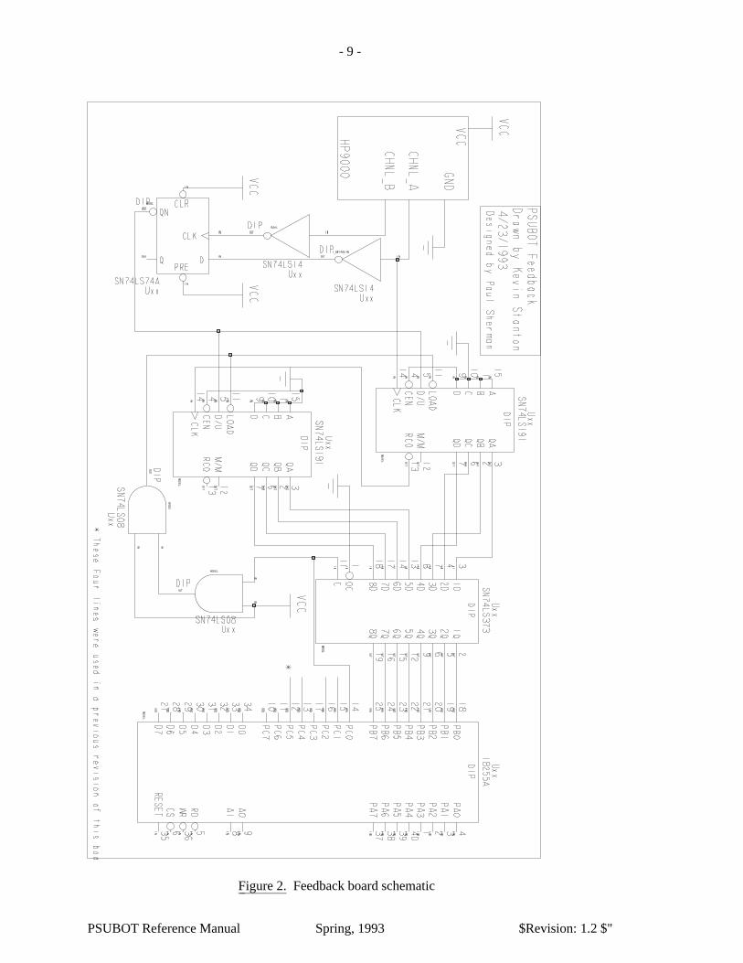
2.3. Feedback Board SchematicFollowing, in figure 2, is the schematic for the feedback board as used currently in the PSU-
BOT. It does not include the multiplexer or the additional D flip-flop as described above, thoughthey are in fact on the board itself. For a diagram of the original intent, see the report by PaulSherman.
2.4. Software Device Driver fundamentalsTo read the distances traveled by the wheels, the latch signal first goes low. Then the two
counts are read from the feedback board, and the latch signal goes back high. While the latch islow, the counters are told to load the value on their inputs. This value is binary 10000000, or
PSUBOT Reference Manual Spring, 1993 $Revision: 1.2 $"
- 8 -
0x80. In this way, the actual number of counts may be obtained by subtracting 128 from theinput value. If more than 128 counts are detected between reads from the computer, the resultwill be incorrect.
Also note that while the latch output is low, the counters are disabled, and any pulses occur-ing during that time will be lost. Therefore it is important that the duration of the low pulse onthe latch output be as short as possible.
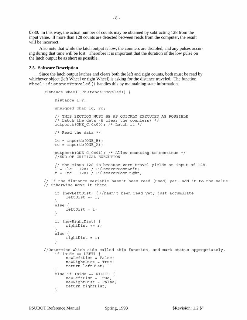
2.5. Software DescriptionSince the latch output latches and clears both the left and right counts, both must be read by
whichever object (left Wheel or right Wheel) is asking for the distance traveled. The functionWheel::distanceTraveled() handles this by maintaining state information.
Distance Wheel::distanceTraveled() {
Distance l,r;
unsigned char lc, rc;
// THIS SECTION MUST BE AS QUICKLY EXECUTED AS POSSIBLE/* Latch the data (& clear the counters) */outportb(ONE_C,0x00); /* Latch it */
/* Read the data */
lc = inportb(ONE_B);rc = inportb(ONE_A);
outportb(ONE_C,0x01); /* Allow counting to continue *///END OF CRITICAL EXECUTION
// the minus 128 is because zero travel yields an input of 128.l = (lc - 128) / PulsesPerFootLeft;r = (rc - 128) / PulsesPerFootRight;
// If the distance variable hasn’t been read (used) yet, add it to the value.// Otherwise move it there.
if (newLeftDist) { //hasn’t been read yet, just accumulateleftDist += l;
}else {
leftDist = l;}
if (newRightDist) {rightDist += r;
}else {
rightDist = r;}
//Determine which side called this function, and mark status appropriately.if (side == LEFT) {
newLeftDist = False;newRightDist = True;return leftDist;
}else if (side == RIGHT) {
newLeftDist = True;newRightDist = False;return rightDist;
}
PSUBOT Reference Manual Spring, 1993 $Revision: 1.2 $"
- 9 -
Figure 2.�������� Feedback board schematic
PSUBOT Reference Manual Spring, 1993 $Revision: 1.2 $"
- 10 -
return 0;}
3. Higher Level Software Modules
Figure 3.�������� Wheelchair Motion Object Hierarchy with Inheritance
3.1. PID Controller ObjectA PID controller stands for Proportional + Integral + Derivative control algorithm, and indi-
cates how the error (difference between the desired and actual quantity (speed)) are combined togenerate the command output). The core of the PID controller was developed by Karl Radestamas a 406 project. The code was written in C and I generated a C++ class with it. It has twoforms; velocity and positional. The velocity form (currently the one used) was modified slightlyby myself so that the proportional term didn’t go away after the first iteration (as would havebeen the case with the straight PID algorithm). The interface to the object is very straight-forward. Upon construction it sets up the arrays used in the calculations, and reads the constants(KP, KI and KD) from the Parameters object. Of course the destructor frees the memory taken upby the arrays, and the two remaining member functions do the actual PID calculation (work()),and reset the state of the PID if a new context is desired.
class PID {
public:PID();˜PID();
float work(Speed &desired, Speed ¤t, float& T);void reset(); //Clear the state of the PID
private:
int length; //This must be before the K[PID] declarations!!!float KP;float KI;float KD;
float *e; //Error arrayfloat *m; //Command array
};
Notice that the order of declaration of private members is critical, since the length of the arraysmust be defined before the arrays themselves are defined. The order in which the members areinitialized in the constructor is of no consequence; the order of declaration ultimately determinesthe order of initialization.
3.2. Wheel ObjectThe Wheel object is responsible for operating a wheel at a particular speed, and maintain a
record of what distance the outer surface of the wheel has travled. There are command functions,such as setSpeed, motorOff, there are status functions such as currentSpeed, distanceTraveled,and finally the work() function actually polls the object to allow it to do all the controlling andstatus-update operations.
enum SIDE { LEFT, RIGHT };
PSUBOT Reference Manual Spring, 1993 $Revision: 1.2 $"
- 11 -
class Wheel {
public:
Wheel(SIDE s);˜Wheel();
void work();void setSpeed(Speed s);Distance travel() {return cumulativeDistance; }void resetTravel();Speed speed() {return currentSpeed; }void motorOff();void markTime(); //Don’t control, just read distances.
private:���
3.3. PathSegment Base-Class (contains two Wheel objects)The PathSegment class is never instantiated, but rather is the base class of all objects which
represent a robot motion, such as Forward, Rotate, Stop, and all extensions which will undoubt-edly appear later (Arc, Sideways, etc.). The goal of this class was to encapsulate those data andfunction members which would be common to all such higher-level classes. The most basicmembers of the PathSegment class are the left and right Wheel classes. Clearly each of themotions just mentioned require the control of both wheels. Also included is all functions neces-sary to calculate and maintain the current Posture of the robot based on odometry (distance read-ings from each wheel).
This class also uses a feature of the C++ language which no other class in the system uses:virtual functions. In this case, the functions are Pure Virtual Functions (as can be seen by the ‘‘=0’’ at the end of their declaration) and therefore the class PathSegment is an Abstract Class. Butthis is what we want, since it would not make sense to tell the PathSegment directly to work(),since work() has no meaning until it is inherited (and thereby defined) in the derived class(Forward, for example). A benefit is that all classes which make PathSegment a base-class, mustdefine a minimum interface which is expected by the Motion class or a compile-time error willresult. Thus we can guarantee that the function-call interface for each derived class will be con-sistant.
class PathSegment {
public:
PathSegment(Posture loc);
virtual void work() = 0;virtual void pause() = 0;virtual void continueNow() = 0;virtual Angle shieldDirection() = 0; //Which direction to watch for collisions
Boolean done() {return finished;}void setPosture(Posture p) {current = p;}Posture currentPosture() {return current;}void calculatePosture(Distance l, Distance r);void reset(); // Turn the motors off
protected: //Derived functions may call these directly, private// to everyone else.
Angle deltaTheta;
PSUBOT Reference Manual Spring, 1993 $Revision: 1.2 $"
- 12 -
Boolean finished, pausing;Posture current;Time pauseStart;
virtual void setSpeeds() = 0;Wheel left, right;
};
3.4. Forward, Rotate, Stop objects (inherit PathSegment Object)Once the abstract base class (PathSegment) had been defined, the derived classes must sim-
ply define custom functions to be used when the pure-virtual functions of the base class arecalled. These include: work(), pause(), continueNow(), shieldDirection(),and setSpeeds().
Forward:The Forward object simply assigns the default maximum-speed to both the left and rightwheels as their desired speeds. It returns 0° as the shieldDirection() (though 180°
would be appropriate for negative speeds (reverse)) and the work() function defineswhen the motion is completed. It would probably be a good idea to include all commoncommands of the work() function of all the derived classes of PathSegment into a com-mon function, which then would call a pure virtual function to detect the termination condi-tion.
class Forward: public PathSegment {
public:
Forward(Distance dist, Posture p);
void pause();void continueNow();void work();Angle shieldDirection();
private:
Speed ForwardSpeed; //Desired wheel speedsDistance desiredDistance, totalTravel;void setSpeeds();
};
Rotate:The Rotate object returns the correct direction (±180°) for the shieldDirection()function, and accumulates the total rotation amount to determine when the correct angle isachieved.
class Rotate: public PathSegment {
public:
Rotate(Angle ang, Posture p);
void pause();void continueNow();void work();Angle shieldDirection(); //Which way to look out
private:
Angle desiredRotation;
PSUBOT Reference Manual Spring, 1993 $Revision: 1.2 $"
- 13 -
Angle initialHeading;Angle rotatedSoFar;int CW; //This is +-1void setSpeeds();Speed RotateSpeed;//Default maximum rotation speed
};
Stop: The Stop object simply maintains the odometry-based position of the robot, and tries tokeep both wheels stopped. It also has a termination condition; that of the wheels speedsboth being lower than some threshold.
class Stop: public PathSegment {
public:
Stop(Posture loc);
void pause();void continueNow();void work();Angle shieldDirection();
private:
void setSpeeds();Speed StopSpeed; //Speed at which we are assumed to have stopped.
};
3.5. Motion Object (executes a Forward, Rotate, or Stop)The Motion object is nothing more than a place to hold a pointer to a PathSegment (which
is actually one of the derived classes, but pointers to an objects’ base-class are allowed) and func-tions which pass function-calls to the current motion type. In other words, it provides a con-venient interface between the higher-level classes and the low-level motion-types. Thus ahigher-level function can tell the motion object that it wants a Forward object to be the currentexecuting pathsegment, and then another higher-level function tell the Motion object towork(), at which time it would execute the current segment (which would be a Forward object).
class Motion {
public:Motion();˜Motion();
Boolean done();
// here are the motions availablevoid forward(Distance dist);void rotate(Angle ang);void stop();
Angle shieldDirection(); //Watch for collisions here (theta)void work();void pause();void continueNow();
Posture currentPosture();void setPosture(Posture& pos);void reset(); // Turn the motors off.
private:PathSegment *currentSegment; //The segment currently being executed
PSUBOT Reference Manual Spring, 1993 $Revision: 1.2 $"
- 14 -
};
So, for example, the definition of the member function ::forward(Distance d) isas follows:
void Motion::forward(Distance d) {Posture p = currentPosture(); //Find out where we are firstdelete currentSegment;currentSegment = new Forward(d,p); // Give it the current postureif (!currentSegment) {
noMem();}
}
and a call to work() would be simply executing the following one-liner:
void Motion::work() {currentSegment -> work();
}
The other members of this class are very similar. Notice that as each segment is constructedwhen desired, it is passed the odometry-based, believed posture. Graphically, each segment isgiven its starting point (Posture), and yields its endpoint (Posture) just before its destructor iscalled.
III. Sonar Sytem:
1.Sonar Device
Concepts of operationBrief overview of hardware (commercially available)Digital Signal InterfaceSoftware Device Driver
2. Sonar Rotation DeviceSince we wanted to be able to look in more than just one direction with the sonar, the ultra-
sonic trasnducer was connected (by a piece of toilet-bowl tubing, I might add) to a stepper-motormounted with the shaft oriented vertically.
2.1. Source for circuit, driver chipThe cheapest stepper motor/driver I found was from a company called Mavin P. Jones Inc.
(XXXXX address and phone number) and was sold in the form of a kit. Well, when the kit came,I discovered that the circuit was not very useful. For one, the user had to push a button to make itstep each time, or could hook the step-input to a 555 astable timer and then adjust the frequencyby turning a potentiometer. Also, the direction was controlled by a switch. What we needed wasall these things controlled by logic-level signals from the computer.
Dispite little experience with signal-level conversions, I managed to get the circuit to workby using simple emitter follower (?????) circuits to ground the input when the logic level washigh. This worked, except that after more thorough testing I discovered that between times whenthe line was pulled low by the transistor, the line bascially floated and picked up lots of straynoise (especially when the PWM drive motors were operating), resulting in erratic stepping of themotor. This was solved by putting a pull-up resistor on the line, something that should have beenpart of the initial circuit.
PSUBOT Reference Manual Spring, 1993 $Revision: 1.2 $"
- 15 -
2.2. Hardware Description (Circuit with modifications)Basically, the circuit is simply a XXXXYYYY stepper-motor controller connected to +12V.
Level tranlsation (as described above) allows control of the chip with logic-level signals. Havinglearned much and seen numerous power-conversion circuits since the circuit was built, I expectthat another chip with direct logic inputs would be a good choice as a replacement.
��������������������������������������������������������������������������������������������
��������������������������������������������������������������������������������������������
Figure 4.�������� Sonar Rotation Device Circuit
2.3. Software Device DriverThe software for driving the stepper motor involves simply setting a pair of bits in port
THREE_C. Bit 0 tells the chip when to step, and bit 1 tells which direction to step (bit 5 indi-cates the ‘‘home’’ position). The basics of the software was written by Robert Gatlin (who alsoput the sonar device together).
The result of the logical AND of the value from port THREE_C with 0x10 is zero if theoptical detector is blocked (home position) and one otherwise.
Bit 1 of port THREE_C indicates the direction the motor is to step. A one indicates coun-terclockwise rotation (positive angles) and a zero in that bit position indicates a clocwise rotationis desired. Bit zero of port THREE_C is the step signal. A transition of this bit from 1 to 0 (withbit one set appropriately to indicate direction) steps the motor one step in the appropriate direc-tion. A delay is introduced between steps to put a ceiling on the step rate. Following is a code-segment which steps a specified number of steps in the specified direction:
void Sonar::step(int steps) {
int direction;if (steps > 0)
direction = 0x02;else
direction = 0x00;for (int i = 0; i < abs(steps); i++) {
outportb(THREE_C,(0x01|direction));outportb(THREE_C,(0x00|direction));delay(StepDelay);
}sonarPosition += steps;
}
PSUBOT Reference Manual Spring, 1993 $Revision: 1.2 $"

- 16 -
3. The Sonar ObjectThe Sonar object is responsible for all interactions with the sonar sub-systems, including
reading distances and maintaining the current sonar-heading. Since the sonar device is mountedon a stepper-motor, a particular maximum number of steps are obtainable, thus some roundingmay occur, for example, when the object is told to point in the direction of 90° (1.5 radians).Since the distance value returned from the hardware was meant to light a 7-segment display, aconversion function is included (lookupNum()).
Everything is in place for the sonar to be able to ‘‘home’’ itself by means of a photo-interruptor module mounted on the sonar pedistal. However, currently there is no linkage whichtravels around with the sonar transducer to break the light path, so a piece of black electrical tapeis place in the slot so that the Sonar object always thinks it is in the home position (whenever itchecks).
All functions one would like to have in the Sonar object are present, including the raw dis-tance ahead, the current angle, the number of steps in a complete revolution, the ability to set theangle or directly step a specific number of steps, and finally, an array of points may be returnedwhich represent a full 360° scan of the current room as seen by the sonar.
class Sonar {
public:
Sonar();
Distance distance(); //in feetAngle angle(); //in radiansvoid setDirection(Angle ang);//in radiansvoid home();void step(int steps); //+ is clockwisePointArray& scan();int numOfScanPoints();
private:
int totalSteps; //Steps in one revolutionint StepDelay; //How many ms to wait between steps.
Boolean positionKnown;int sonarPosition; //in radians
Boolean atHome();void init();void resetTransducer();void transmit_sonar(); //Chirp itvoid reset_everything();char lookupNum(int number); //convert 7-seg to decimal
float radiansPerStep;Distance MaxDistance; //Prune any sounding more distant
PointArray scanPoints; //360 degree scan};
IV. Compass:
PSUBOT Reference Manual Spring, 1993 $Revision: 1.2 $"
- 17 -
1. OverviewRadio Shack makes (made) a flux-gate compass for use in automobiles. Since the internals
were elctrical signals, it seemed that if we could tap into the right lines, a computer could deducethe heading of the robot. Upon removing the cover and investigating, an MC3403 Quad Dif-ferential Input Operational Amplifier was found which amplified two sinusoids. From those twosinusoids we were able to calculate the heading as indicated by the compass.
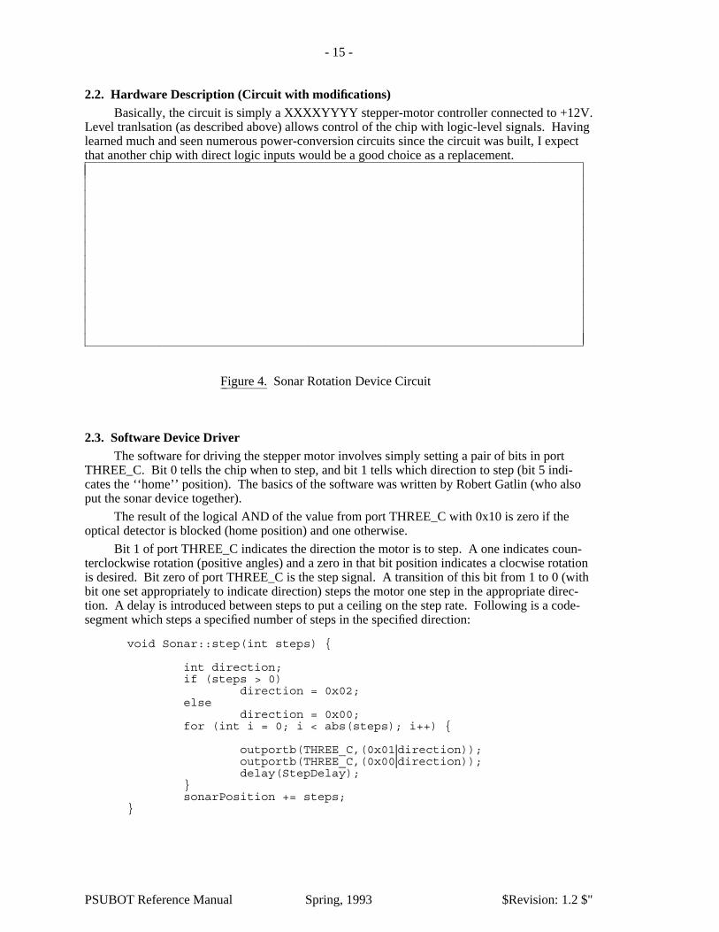
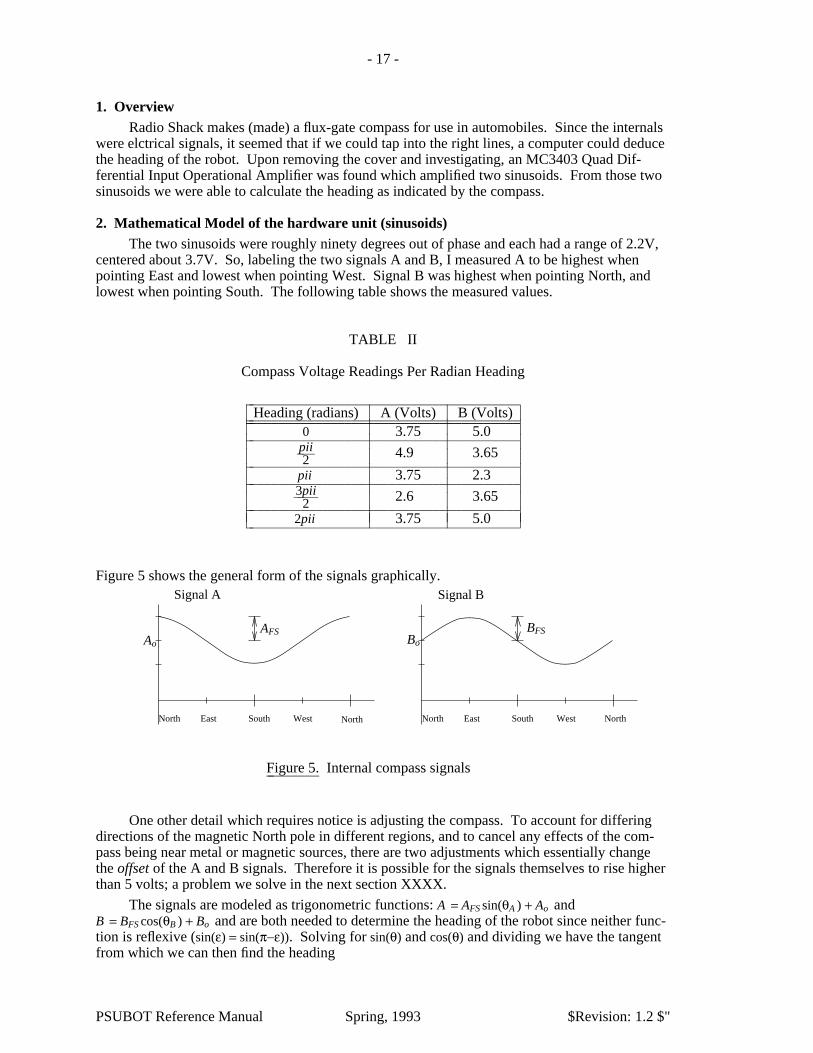
2. Mathematical Model of the hardware unit (sinusoids)The two sinusoids were roughly ninety degrees out of phase and each had a range of 2.2V,
centered about 3.7V. So, labeling the two signals A and B, I measured A to be highest whenpointing East and lowest when pointing West. Signal B was highest when pointing North, andlowest when pointing South. The following table shows the measured values.
TABLE II
Compass Voltage Readings Per Radian Heading
��������������������������������������Heading (radians) A (Volts) B (Volts)������������������������������������������������������������������������������������������������������������������
0 3.75 5.0��������������������������������������
2pii��� 4.9 3.65��������������������������������������pii 3.75 2.3��������������������������������������
23pii���� 2.6 3.65��������������������������������������2pii 3.75 5.0����������������������������������������
�������
���������
���������
���������
Figure 5 shows the general form of the signals graphically.Signal BSignal A
AFSAo
NorthSouthEast WestNorth North WestEast South North
Bo
BFS
Figure 5.�������� Internal compass signals
One other detail which requires notice is adjusting the compass. To account for differingdirections of the magnetic North pole in different regions, and to cancel any effects of the com-pass being near metal or magnetic sources, there are two adjustments which essentially changethe offset of the A and B signals. Therefore it is possible for the signals themselves to rise higherthan 5 volts; a problem we solve in the next section XXXX.
The signals are modeled as trigonometric functions: A = AFS sin(θA ) + Ao andB = BFS cos(θB ) + Bo and are both needed to determine the heading of the robot since neither func-tion is reflexive (sin(ε) = sin(π−ε)). Solving for sin(θ) and cos(θ) and dividing we have the tangentfrom which we can then find the heading
PSUBOT Reference Manual Spring, 1993 $Revision: 1.2 $"

- 18 -
θ = tan−1
�������
��� BFS
B −Bo�������
��� AFS
A −Ao����������������
�����
3. Analog Input boardAs described in section XXXX, the analog input board may be used to convert up to eight,
0-5V signals to an 8-bit quantity. However, as noted above, it would found that to keep the com-pass signals stable, the signal voltages could rise above 5 volts (in fact, the compass was ulti-mately adjusted so that the maximum voltages were in the neighborhood of 5.8 volts). We solvedthis in the simplest (and crudest) manner possible: with a simple set of voltage dividers. Figure 6shows the adjustable resistor pairs which can cut down the voltage.
VinBVinA VoutBVoutA
10K
1K 1K
10K
Figure 6.�������� Compass signal voltage dividers
4. Driving SoftwareThe device driver for the compass is a compound object called Compass. Internally, there
is another object called CompassInput which actually performs the A/D conversion, does an ini-tial calibration to determine the min and max values to be expected (requires a complete spin ofthe compass (robot) upon initialization to get this information), and calculates the normalizedsinusoid value [-1,1].
4.1. CompassInput ObjectThis class is nested internal to the Compass class (and private: too). It is necessary to call
initialize() often while spinning the robot 360 degrees to allow the class to build up acomplete and accurate estimate of the minimum and maximum values from the input channel.
class CompassInput {
public:CompassInput(char which);˜CompassInput();int raw();// initialize is called repeatedly while rotating.int initialize();float sineValue();Boolean goodInit();
private:unsigned char channel; // N/S or E/Wint delay; //Needed to allow the A/D converter to settleint min,max; //Used for calibrationfloat SinusoidValue;int *powerArray; //Holds powsers of two
};
PSUBOT Reference Manual Spring, 1993 $Revision: 1.2 $"
- 19 -
The sineValue() function calculates the value of a unit sinusoid (-1 to 1) representedby the current value read from the A/D port. This is accomplished by scaling by the expectedfull-scale and shifting by the average expected full-scale as seen below:
float Compass::CompassInput::sineValue() {
float theValue;float ave, fullscale;
ave = (max + min) / 2;fullscale = max - min;
float r = raw(); //Read the raw value from the porttheValue = (r - ave) / (fullscale / 2);
return val;}
4.2. Compass ObjectSince the CompassInput class takes care of much of the ‘‘dirty work’’, the Compass object
simply provides a friendly interface to the lower level operations. Of particular interest is theheading() command. As seen above from the equations, the heading is simply the tan−1 of thetwo sinusoids. Following is the heading() function of the compass object:
Angle Compass::heading() {
Angle heading = atan2(east.sineValue(), north.sineValue());
heading = NortherlyAngle - heading;
//Normalize the heading to be in the range [-pi,pi]while (heading > Pi) heading -= TWO_PI;while (heading < -Pi) heading += TWO_PI;
return heading;}
Notice also that any heading may be assigned zero degrees (the NortherlyAnble). This allows theCompass class to adapt to a building which might not have zero degrees assigned as pointingnorth.
5. Performance/Suggested ImprovementsThe accuracy of the Compass system is far less than its resolution. Several components
may be contributing to this problem of accuracy: The sinusoids may not be precisely 90° out ofphase, slight tilts in the flux-gate sensor may cause radical changes in the reported heading, metalnear the sensor may skew the results, among others. The first problem (I think the most likelycandidate) could be solved with a little better characterization of the signals during initialization,including sinewave-parameter estimation techniques. The second two could possibly be solvedwith better mounting of the sensor, or moving to a better suited, commercial digital compass.
V. Voice Recognition
1. IntroductionThe voice recognition system currently in place on the PSUBOT is called Voice Master
Key from COVOX corporation in Eugene, OR. The system was purchased in 1989 for under$200. From the outset I would like it known that clearly there are better and even less expensive
PSUBOT Reference Manual Spring, 1993 $Revision: 1.2 $"
- 20 -
systems available (even from the same company).
The system consists of a headset with a microphone and headphones, a interface boardwhich plugs into the computer, and demonstration and driver software. The demonstrationsoftware includes a digital oscilloscope, a crude frequency spectrum. The driver software is aTSR which activates when a key sequence is detected or when something is spoken into themicrophone. In either case, the software takes full control of the CPU so that whatever was run-ning previously sleeps.
The system works by the user training it to recognize words. A minimum of three and amaximum of nine trainings are allowed. Up to 256 words may be loaded at one time, thoughonly 16 may be active (chosen from) at any given time. However, once one word is recognized,it may activate a different ‘‘template’’ of 16 words, and so on.
Once a word is recognized, it is inserted into the DOS keyboard-input buffer for processingas though it were typed in. This turned out to be a problem for us since Borland C++ seems touse BIOS routines to read the keyboard, and BIOS knows nothing of DOS. It was thereforenecessary to perform a DOS (INT21) interrupt from the program to ask DOS about its keyboardinput buffer. This is described in more detail a little later on.
2. Device DriverThe Voice object knows how to ask DOS if there is a character waiting from the keyboard,
and then knows how to read one character. This was necessary (rather than just the standardin/out) because Borland C++ seems to read keyboard input directly from the BIOS routines ratherthan DOS, and the voice recognition system stuffs characters into the DOS buffers, not the BIOSbuffers. Following is the (simple) header definition of the Voice class:
class Voice {
public:Voice();
Boolean characterReady();char next(); //Read a character
private:};
Both member functions use the intdos() function call, which requires some explanation.First, there is a register union, called REGS which stores the a,b,c,d, etc 80X86 register valuesbefore and after a system call. So, to test the keyboard input-buffer to see if anything is there,one must simply give the DOS interrupt a value of 0x0B in the AH register, and the interruptreturns with either 0x00 (no) or 0xFF (yes) in the AL register.
Reading a character requires 0x01 in the AH register, the result is then found in the ALregister.
Boolean Voice::characterReady() {// A regular C stdio function won’t work, since the VMKEY interface stuffs// characters into the DOS buffer, but somehow the BIOS routines can’t// tell they are there (borland uses the BIOS routines)//// Otherwise a function such as "int kbhit()" would do the same thing.//
union REGS inregs, outregs;
inregs.h.ah = 0xb;intdos(&inregs,&outregs); // Perform a DOS interrupt (0x0b)
return (outregs.h.al); // 0x00 if none, 0xff if one or more
PSUBOT Reference Manual Spring, 1993 $Revision: 1.2 $"

- 21 -
}
// ****************char Voice::next() {
union REGS inregs, outregs;
inregs.h.ah = 0x01;intdos(&inregs,&outregs); // Perform a DOS interrupt (0x01)
return outregs.h.al;}
3. Caveat:With any non-preemptive multi-tasking environment, if one process takes control of the
CPU and doesn’t relinquish it in a timely manner (as in the case of the above described voicerecognition system), other real-time dependent processes (such as the PID-based wheel con-troller) may not be given the processing time they require. This happened during my thesisdefense demonstration video. While moving, the wheelchair wheels squeeked loud enough tomake the VMKEY software think I was saying something. So, the recognition software tookover, and the PID controller suddently had an update period of one or two SECONDS which isrelatively quite long. It would be exceedingly nice to have the voice recognition a little moremulti-process friendly, or implemented offboard with another processor.
VI. PSUBOT Software System:
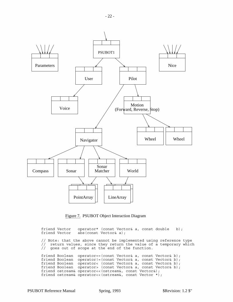
1. OverviewFigure 7 shows the object-interaction diagram for the current PSUBOT configuration. Each
box with a name represents a major system object, and arrows denote which way messages arepassed. (This does not mean that a lower-object cannot communicate with a higher-level object,only that the higher-level must ask the lower-level object for the information.)
2. Data Objects:Several data elements were encapsulated into classes to improve the readability and reliabil-
ity of the resulting code, and for ease of programming. They all basically build upon the Vectordata structure which is described next.
2.1. Vector (point)This class was originally a project assigned in an OCATE Object Oriented Design/C++
course. The goal was to define a Vector and Polar class. The Vector class would have beenbetter named a ’Rectangular’ class, but an assgnment is an assgnment. A Vector takes an x and yparameter, a Polar object takes an r and θ argument. They can be converted to each other, and allPSUBOT software uses the Vector, though Polar are sometimes used in conversions.
The Vector class overloads many operators, and provides many access functions. Follow-ing is a condenced version of the header definition of it.
class Vector {
friend Vector operator+ (const Vector& a, const Vector& b);friend Vector operator- (const Vector& a, const Vector& b);friend Vector operator* (const Vector& a, const Vector& b);friend Vector operator/ (const Vector& a, const Vector& b);
friend Vector operator/ (const Vector& a, const double b);
PSUBOT Reference Manual Spring, 1993 $Revision: 1.2 $"
- 22 -
User
Voice
Pilot
NiceParameters
PointArray
PSUBOT1
Compass Sonar MatcherSonar
Navigator
Motion
Wheel Wheel
(Forward, Reverse, Stop)
World
LineArray
Figure 7.�������� PSUBOT Object Interaction Diagram
friend Vector operator* (const Vector& a, const double b);friend Vector abs(const Vector& a);
// Note: that the above cannot be implemented using reference type// return values, since they return the value of a temporary which// goes out of scope at the end of the function.
friend Boolean operator==(const Vector& a, const Vector& b);friend Boolean operator!=(const Vector& a, const Vector& b);friend Boolean operator< (const Vector& a, const Vector& b);friend Boolean operator> (const Vector& a, const Vector& b);friend ostream& operator<<(ostream&, const Vector&);friend ostream& operator<<(ostream&, const Vector *);
PSUBOT Reference Manual Spring, 1993 $Revision: 1.2 $"

- 23 -
friend istream& operator>>(istream&, Vector&);
public:
// CONSTRUCTORS
Vector() { Real = 0; i = 0; }Vector(double real, double imag) { Real = real; i = imag; }Vector(const Vector& v) { Real = v.Real; i = v.i; }Vector(const Polar& p); //implicit conversion from
//Polar to Vector.
// NON-SYMMETRIC ARITHMETIC OPERATORS
Vector& operator+=(const Vector& c);
Vector& operator-=(const Vector& c);
Vector& operator*=(const Vector& c);
Vector& operator/=(const Vector& c);
// OTHERSdouble& real() { return Real; }double& x() { return Real; }double& imag() { return i; }double& y() { return i; }double radius() const { return sqrt(Real*Real + i*i); }double angle() const;char operator<= (const Vector& a);char operator>= (const Vector& a);
void rotate(const double);
private:// Here is the cartesean data that represents the value of// this complex number.
double Real;double i;
};
So, using the above class, it would be possible to perform the following actions with two byone vectors (which probably does nothing useful in this case):
Vector PointA(-5,2), PointB(3,2), PointC;
PointC = (PointA++ - PointA) * Vector(1, -1);
if (PointC >= Vector(-1,-1))cout << PointC.y();
elsecout << PointC.x();
With the addition of the Polar class (not shown here), it is possible to easily tranlate polarcoordinates to rectangular, as is done in the Sonar class:
Vector sonarDataPoint = Polar(radialDistance, currentSonarHeading);
The resulting sonarDataPoint is a regular Vector object, and was converted automatically with a‘‘user defined conversion’’ (one of the Vector constructors which accepts an instance of the Polarclass as its argument).
PSUBOT Reference Manual Spring, 1993 $Revision: 1.2 $"

- 24 -
A Vector may also be created from user input using the standard extraction operator; >>.The exact format of the input expected is defined in the .c files where the operator>> is defined.
2.2. PostureThe robot’s location is defined not only in two-dimensional space, but also in terms of a
heading. Therefore it was convenient to define another class which would hold the current x ,yposition as well as the robot’s heading θ.
class Posture {
friend ostream& operator<< (ostream& os, Posture& p);friend istream& operator>> (istream& is, Posture& p);friend Posture abs(const Posture& p);
public:Posture(const Distance x, const Distance y, const Angle heading);Posture(const Vector vec, const Angle heading = 0);Posture(Posture& p){ disp = p.disp; theHeading = normalizeHeading(p.theHeading);}
Posture(); //Set all data members to zero
Boolean operator==(Posture &p);Boolean operator<(Posture &p); //Checks both disp and angleBoolean operator>(Posture &p); //Checks both disp and angleDistance& x() { return disp.x(); }Distance& y() { return disp.y(); }Posture operator+(Posture&);Posture operator-(Posture&);Angle& heading() { return theHeading; }Angle& theta() { return theHeading; }Angle& angle() { return theHeading; }void addDisplacement(Vector vec) { disp += vec; }Vector& displacement() { return disp; }Vector& vector() { return disp; }void addHeading(Angle theta);void setDisplacement(Vector& displacement)
{ disp = displacement; }void setHeading(Heading newHeading)
{ theHeading = normalizeHeading(newHeading); }
private:Angle normalizeHeading(Angle &a); //Constrain -PI <= a <= PIVector disp;Angle theHeading;
};
Notice that many of the operations rely on the functions available from the Vector class.
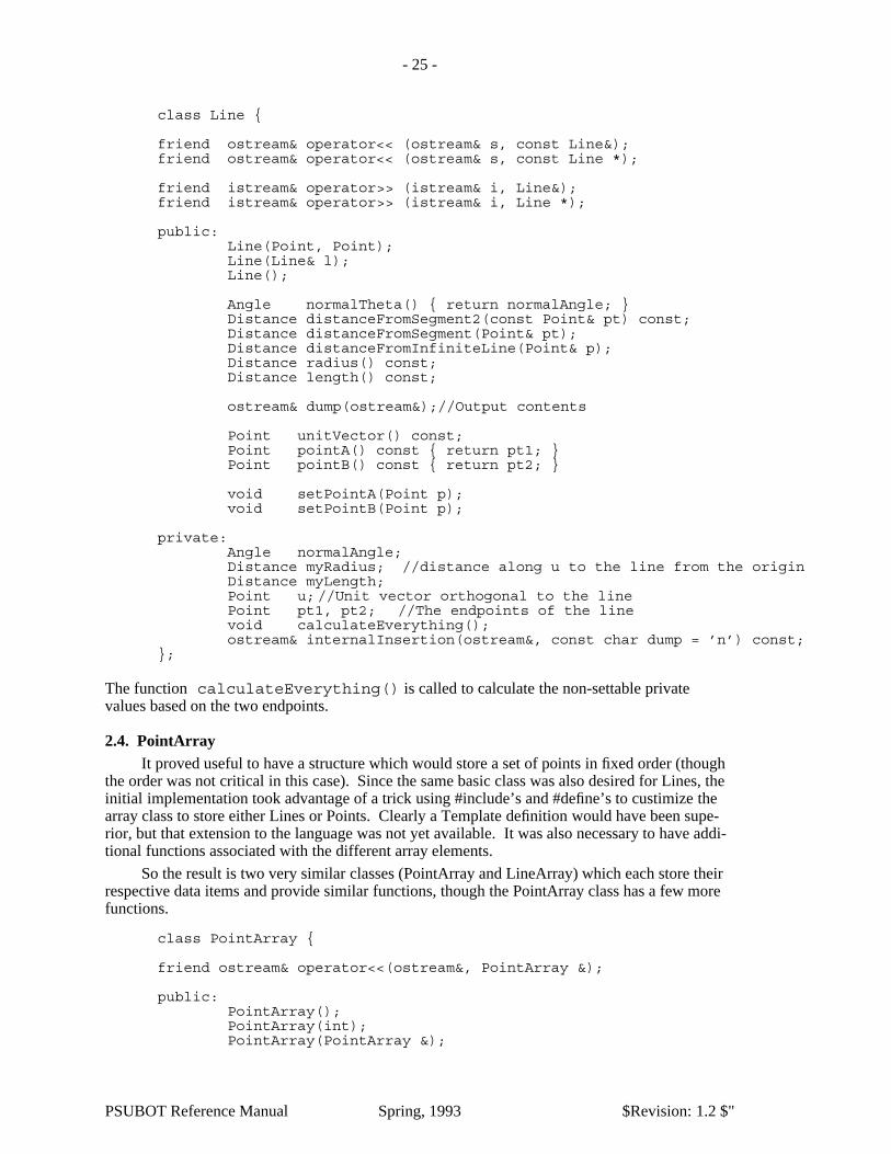
2.3. LineSince the model of the room used in the matching algorithm developed for my thesis rely
on line segments, I thought it fitting to develope a line class which could be optimized for compu-tational efficiency and programming ease. The efficiency was accomplished by calculating allparameters of the line on construction (or when the line was changed) so that subsequent requestsfor the length of the line, for example, was reduced to a mere return of a reference to that pre-calculated quantity.
A Line may be constructed from either a pair of points, or another line (the copy construc-tor). However, member functions are avilable to tell the length of the line, the distance from anarbitrary Point (Vector) to that line (taking into account all three possible cases of orientation),distance from the origin, unit vector from origin which is orthogonal to the line, among others.Follwing is a listing of the header file:
PSUBOT Reference Manual Spring, 1993 $Revision: 1.2 $"
- 25 -
class Line {
friend ostream& operator<< (ostream& s, const Line&);friend ostream& operator<< (ostream& s, const Line *);
friend istream& operator>> (istream& i, Line&);friend istream& operator>> (istream& i, Line *);
public:Line(Point, Point);Line(Line& l);Line();
Angle normalTheta() { return normalAngle; }Distance distanceFromSegment2(const Point& pt) const;Distance distanceFromSegment(Point& pt);Distance distanceFromInfiniteLine(Point& p);Distance radius() const;Distance length() const;
ostream& dump(ostream&);//Output contents
Point unitVector() const;Point pointA() const { return pt1; }Point pointB() const { return pt2; }
void setPointA(Point p);void setPointB(Point p);
private:Angle normalAngle;Distance myRadius; //distance along u to the line from the originDistance myLength;Point u; //Unit vector orthogonal to the linePoint pt1, pt2; //The endpoints of the linevoid calculateEverything();ostream& internalInsertion(ostream&, const char dump = ’n’) const;
};
The function calculateEverything() is called to calculate the non-settable privatevalues based on the two endpoints.
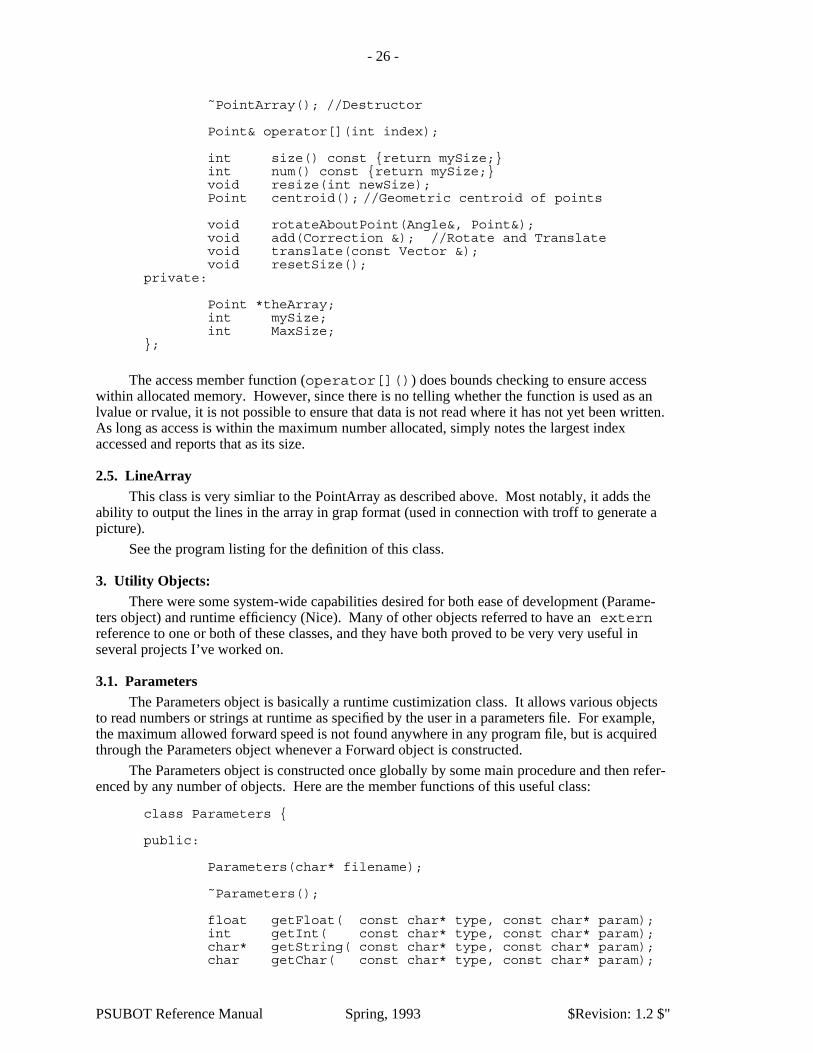
2.4. PointArrayIt proved useful to have a structure which would store a set of points in fixed order (though
the order was not critical in this case). Since the same basic class was also desired for Lines, theinitial implementation took advantage of a trick using #include’s and #define’s to custimize thearray class to store either Lines or Points. Clearly a Template definition would have been supe-rior, but that extension to the language was not yet available. It was also necessary to have addi-tional functions associated with the different array elements.
So the result is two very similar classes (PointArray and LineArray) which each store theirrespective data items and provide similar functions, though the PointArray class has a few morefunctions.
class PointArray {
friend ostream& operator<<(ostream&, PointArray &);
public:PointArray();PointArray(int);PointArray(PointArray &);
PSUBOT Reference Manual Spring, 1993 $Revision: 1.2 $"
- 26 -
˜PointArray(); //Destructor
Point& operator[](int index);
int size() const {return mySize;}int num() const {return mySize;}void resize(int newSize);Point centroid(); //Geometric centroid of points
void rotateAboutPoint(Angle&, Point&);void add(Correction &); //Rotate and Translatevoid translate(const Vector &);void resetSize();
private:
Point *theArray;int mySize;int MaxSize;
};
The access member function (operator[]()) does bounds checking to ensure accesswithin allocated memory. However, since there is no telling whether the function is used as anlvalue or rvalue, it is not possible to ensure that data is not read where it has not yet been written.As long as access is within the maximum number allocated, simply notes the largest indexaccessed and reports that as its size.
2.5. LineArrayThis class is very simliar to the PointArray as described above. Most notably, it adds the
ability to output the lines in the array in grap format (used in connection with troff to generate apicture).
See the program listing for the definition of this class.
3. Utility Objects:There were some system-wide capabilities desired for both ease of development (Parame-
ters object) and runtime efficiency (Nice). Many of other objects referred to have an externreference to one or both of these classes, and they have both proved to be very very useful inseveral projects I’ve worked on.
3.1. ParametersThe Parameters object is basically a runtime custimization class. It allows various objects
to read numbers or strings at runtime as specified by the user in a parameters file. For example,the maximum allowed forward speed is not found anywhere in any program file, but is acquiredthrough the Parameters object whenever a Forward object is constructed.
The Parameters object is constructed once globally by some main procedure and then refer-enced by any number of objects. Here are the member functions of this useful class:
class Parameters {
public:
Parameters(char* filename);
˜Parameters();
float getFloat( const char* type, const char* param);int getInt( const char* type, const char* param);char* getString( const char* type, const char* param);char getChar( const char* type, const char* param);
PSUBOT Reference Manual Spring, 1993 $Revision: 1.2 $"

- 27 -
private:
Boolean Initialized;char *first, *second, *string;
};
So each member function finds a different type of parameter - float, int, char*, char - and isgiven two char* parameters. My convention was to pass the name of the object as the firstparameter (the ‘‘type’’ parameter), and the parameter name as the second string. So, when theForward class is constructed, it performs a call to the getFloat() function
ForwardSpeed = param->getFloat("forward","speed");
This runtime resolution of execution parameters allows quick modification of system variablesduring debugging and performance evaluation.
There is currently no method of changing parameters in the parameters file (commonlycalled ‘‘param.dat’’), though such a capability could prove useful in the future. It would also benice to get the compiler to figure out which of the four functions to call based on the type of thevariable to which the value is being assigned.
3.2. NiceThe Nice object was used to divide execution time ‘‘fairly’’ between major objects as the
nice(1) command in UNIX adjusts priority of a process, though not as well. The concept is this;there is a main execution loop which tells each major object to work(). Thus each object iscalled an equal number of times. However, since some tasks require smaller periods betweenworking, it was necessary to cause the other objects to basically skip a certain number of execu-tions of their work() function.
This was accomplished by having a global Nice object which would keep a tally of howmany times each object requested execution priviledges (each time their work() function wascalled) and would turn them down a predefined number of times. Thus the Wheel class would beallowed to execute each time its work() function was called, while the PathSegment class(which does some numeric computations) would be allowed to execute its routines only afterevery 15 requests, for example. Following is the header file for the Nice class:
//The following is a list of all possible Object Types recognized.enum ObjectType { _Start,WHEEL,MOTION,MATCHER,NAVIGATOR,PILOT,USER,_Finish };
class Nice {
public:
Nice();˜Nice();
Boolean myTurn(ObjectType obj);
private:
ObjectType modTotal[12]; //How often each gets to executeint modCount[12]; //# times left to ask before grant
PSUBOT Reference Manual Spring, 1993 $Revision: 1.2 $"

- 28 -
};
Clearly this object is of minimal implementation and better management of the real-timeaspects of the PSUBOT will be necessary in the future unless a more multi-tasking or real-timeoperating system is employed.
4. Other Files:mdefs.h-
This file is left over from dabbling in Mathematica and converts some of its more readablemathematical outputs to proper C syntax.
object.h-Here is where I define system-wide constants and typedef some common aliases such asBoolean, Speed, Angle, etc.
types.h-This is used only for backward compatibility with some other objects of the past.
ports.h-As described in the section about the PIO96 digital interface board, this header file definesthe I/O space addresses used to access the various custom external hardware devices.
file.h-This file is not needed. It is empty and is simply included in the nice.cpp file.
5. Major System Objects
5.1. Voice Object:The Voice object is described in detail above in the Systems section on the voice recogni-
tion system.
5.2. Command Object:The Command object is nothing more than a portable data structure which can hold all the
different commands the PSUBOT recognizes. Basically the commands were broken down intotwo Types: Action and Goal. Actions included such things as ‘‘stop’’, ‘‘continue’’, ‘‘quit’’, etc.Goals were simply an x , y , θ representation of where the user desired to go. Thus a Commandobject could be passed from one level in the hierarchy to another with minimal information aboutthe object required of the ‘‘passer’’. Once to its destination the receiver could then interrogatethe object for its command type and either its goal or action desired.
Note that additional actions are easily accomodated by simply adding them to the Action-Type enumerated list and modifying the User object (described below) to recognize a user inputas belonging to that action.
enum CommandType { GOAL, ACTION };enum ActionType { STOP, CONTINUE, QUIT, SETLOCATION, STARTAGAIN,
STARTAGIN, PRINTLOCATION, NONE };
class Command {
public:
Command();Command(CommandType t);
void setGoal(Posture p);void setAction(ActionType a);void setType(CommandType t);Posture& goal();
PSUBOT Reference Manual Spring, 1993 $Revision: 1.2 $"

- 29 -
ActionType action();CommandType type() {return theType;}
private:
Posture theGoal;ActionType theAction;CommandType theType;//Determines goal or actionBoolean valid; //Am I (command) valid?
};
5.3. User Object:We desired the ability to enter commands by either voice input or from the keyboard while
the robot was in motion. We also wanted the class responsible for user input to be easily expand-able. While we met the first of these goals, the second one could be improved upon by simplygenerating a data structure with all the allowed commands from which commands could be sim-ply added by typing them in or deleted by removing the corresponding program line.
The User object is allowed to execute by the object above it using the work() functionand is polled for a valid command with the commandReady() member function. Of coursethe command it returns is actually a Command object which is described above. Following is theclass definition:
class User {
public:
User();˜User();
void work();Boolean commandReady();Command readCommand();
private:
Command currentCommand;Boolean validCommand;char buffer[MaxString];int index; //index into character bufferchar* dummy; // Used to read in don’t-care stringsVoice voice; // Tells us what to do.
};
This object, when asked to work(), checks for keystrokes from the keyboard (via the Voiceobject) and collects them until a newline is detected. It then attempts to parse the input line andrepresent it with a Command object.
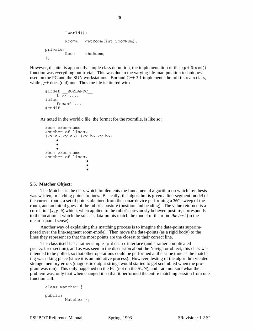
5.4. World Object:The World is simply a file-input class: It can read a Room (which is a LineArray) from a
file. Here is it’s simple class definition:
class World {
public:
World();
PSUBOT Reference Manual Spring, 1993 $Revision: 1.2 $"
- 30 -
˜World();
Room& getRoom(int roomNum);
private:Room theRoom;
};
However, dispite its apparently simple class definition, the implementation of the getRoom()function was everything but trivial. This was due to the varying file-manipulation techniquesused on the PC and the SUN workstations. Borland C++ 3.1 implements the full ifstream class,while g++ does (did) not. Thus the file is littered with
#ifdef __BORLANDC__f >> ....
#elsefscanf(...
#endif
As noted in the world.c file, the format for the roomfile, is like so:
room <roomnum><number of lines>(<x1a>,<y1a>) (<x1b>,<y1b>)
���
room <roomnum><number of lines>
���
5.5. Matcher Object:The Matcher is the class which implements the fundamental algorithm on which my thesis
was written; matching points to lines. Basically, the algorithm is given a line-segment model ofthe current room, a set of points obtained from the sonar-device performing a 360° sweep of theroom, and an initial guess of the robot’s posture (position and heading). The value returned is acorrection (x , y , θ) which, when applied to the robot’s previously believed posture, correspondsto the location at which the sonar’s data-points match the model of the room the best (in themean-squared sense).
Another way of explaining this matching process is to imagine the data-points superim-posed over the line-segment room-model. Then move the data-points (as a rigid body) to thelines they represent so that the most points are the closest to their correct line.
The class itself has a rather simple public: interface (and a rather complicatedprivate: section), and as was seen in the discussion about the Navigator object, this class wasintended to be polled, so that other operations could be performed at the same time as the match-ing was taking place (since it is an interative process). However, testing of the algorithm yieldedstrange memory errors (diagnostic output strings would started to get scrambled when the pro-gram was run). This only happened on the PC (not on the SUN), and I am not sure what theproblem was, only that when changed it so that it performed the entire matching session from onefunction call.
class Matcher {
public:Matcher();
PSUBOT Reference Manual Spring, 1993 $Revision: 1.2 $"

- 31 -
PointArray match(Posture &, LineArray &, PointArray &);
// void work(); //This function removed.Boolean done() { return finished; }Correction &correction();void setNegligableCorrection(const Correction c) {
negligableCorrection = c;}float calculateS(PointArray &, LineArray &, Vector&, Angle);void generateS(Posture &, LineArray &, PointArray &);
private:���
One public member which was added later, was the generateS() function. This wasadded so that I could make pretty pictures for my thesis, like this:
Figure 8.�������� Pretty Picture
5.6. Navigator Object:The Navigator is responsible for maintaining an estimate the position of the robot. Ulti-
mately this could include the sonar matching algorithm, the compass, the odometry, and perhapsother sources of location information. Currently, however, the Navigator ignores the odometry(except as the initial condition for the matching algorithm) and uses the compass only initially toget a rough estimate of the current heading, and it also uses the compass after each matching ses-sion as a litmus test to tell whether the matcher converged to a reasonable location or not. If thecompass and matching algorithm disagree by more than some maximum amount, the softwareterminates. Some more intelligent handling of this condition should be developed in the future.
The Navigator also watches for collisions and may alert the Pilot when an obstacle isdetected too close in the direction of motion.
class Navigator{
public:
Navigator();
Posture ourPosture();Boolean done();void work();
//initiate the localizationvoid whereAreWe(Posture guess, Boolean wild = True);
PSUBOT Reference Manual Spring, 1993 $Revision: 1.2 $"

- 32 -
Boolean inpendingCollision();void watch(Angle direction);void init();Boolean goodInit();
private:
Boolean finished, validLocation;Posture location;Distance minimumSafeDistance;Angle MaxCompassMatcherDiscrepancy;
Matcher matcher; //a matching algorithmCompass compass; //a deviceSonar sonar; //a deviceWorld world; //a world databaseint currentRoomNumber;Room currentRoom;PointArray scan;
};
Two additional items need mentioning. First, the Navigator was initially designed to exe-cute on a polled basis; as do the Pilot, Wheel, and User objects. However, due to problems withthe Matcher I decided to make the matching operation atomic. So the functions done() andwork() are currently not necessary since whereAreWe() does all the work.
The second item to note is that the Navigator requires repetative initialization before usingit. This is due to the Compass, and its need to calibrate itself. Therefore, it is the responsibilityof some other module to ensure that an entire 360° rotation is achieved, though the Compass candetect if no rotation occured.
5.7. Pilot Object: Goals, Abilities Interface (class definition) Code Listing
VII. Custom Demonstration Software to Show Off the PSUBOT
1. PSUBOT1.[hc]Actually, this is a class which invokes and manages the localization-demonstration software
for which all this software was originally written. It’s place in the hierarchy can be seen from theObject diagram in Figure 3. It is the class that is called by the primary main() function until it(the PSUBOT1 object) says it is finished. Here is the class definition, along with the go() func-tion:
class PSUBOT1 {
public:
PSUBOT1();
void go();Boolean finished();
private:
// These are the two objects it likes to talk to.User user;Pilot pilot;
};
PSUBOT Reference Manual Spring, 1993 $Revision: 1.2 $"

- 33 -
and in the .c file,
void PSUBOT1::go() {
Command command;
do {user.work();if (user.commandReady()) {
command = user.readCommand();pilot.command(command);
}pilot.work();variable = 2;
} while ((pilot.status() != DONE) && (pilot.status() != EXIT));}
Boolean PSUBOT1::finished() {
return (pilot.status() == EXIT);}
2. ctest.cThis main() function is used to test the compass. It first asks the user to spin the robot
around at least once and press a space bar. Then it displays the calculated heading of the robotbased on the compass.
3. mtest.cThis main() function demonstrates the minimum setup,etc required to test the wheel
objects, motion object, etc. This can prove invaluable when debugging lower-level moduleswhen, for example, a new controller algorithm is implemented.
4. stest.cThis main() function demonstrates the sonar system. It turns the sonar device to every
radian-specified angle until 0 is entered, at which time it begins displaying the distance aheadeach time a key other than ’q’ is pressed. (’q’ quits).
5. demo.cThis program is more involved than those above. When linked with the correct user and
command files, it allows the user to specify the commands: forward, rotate_left, rotate_right,stop, and quit. This is useful as a simple demonstration of the current capabilities of the PSU-BOT, though it has nothing to do with localization. It does, however, turn the sonar device in thedirection of motion in order to pause when something is seen obstructing the path.
6. graph.cThis main() function continually graphs the current room by spinning the sonar device
around, and plotting the points it sees on the screen. The robot is indicated with a rectangle. Thisis another nice demo of one of the PSUBOT subsystems (Sonar).
PSUBOT Reference Manual Spring, 1993 $Revision: 1.2 $"
- 34 -
References
Hall89a.Douglas V. Hall, Digital Circuits and Systems, Glencoe Division of Macmillan/McGraw-Hill, 1989.
Hall92a.Douglas V. Hall, Microprocessors and Interfacing; Programming and Hardware, GlencoeDivision of Macmillan/McGraw-Hill, 1992.
PSUBOT Reference Manual Spring, 1993 $Revision: 1.2 $"