a904c-us-ntb02.08neu_7364-0
TRANSCRIPT

8/10/2019 A904C-US-NTB02.08neu_7364-0
http://slidepdf.com/reader/full/a904c-us-ntb0208neu7364-0 1/24
Operating Weight: 41,200 - 46,500
Engine Output: 105 kW / 143 H
Bucket Capacity: 0.40 - 1.40 y
A 904 CWheeled Excavator

8/10/2019 A904C-US-NTB02.08neu_7364-0
http://slidepdf.com/reader/full/a904c-us-ntb0208neu7364-0 2/242 A 904 C Litronic
Operating Weight: 41,200 - 46,500 lb
Engine Output: 105 kW / 143 HP
Bucket Capacity: 0.40 - 1.40 yd³
A 904 C

8/10/2019 A904C-US-NTB02.08neu_7364-0
http://slidepdf.com/reader/full/a904c-us-ntb0208neu7364-0 3/24 A 904 C Litronic
EconomyThe Liebherr-Litronic-System increases machine
performance, reduces fuel consumption and mi-
nimises service and maintenance costs. Due to
Liebherr’s well- balanced range, the ideal machine
can always be selected to suit every application.
ReliabilityLiebherr hydraulic excavators have been designed
and built to withstand the toughest of conditions
at the building site. Their rugged design, high-
tensile materials and individual componen-
ts ensure maximum availability and long
life-expectancy.
ComfortLargely dimensioned and ergonomically designed,
the Liebherr excavator cab features an operator’s
seat which can be individually adjusted, as well as
clearly arranged control instruments and ideal all-
round view. Automatic air-conditioning guarantees
an optimum temperature in the Liebherr Feel-Good
cab at all times.
PerformanceLiebherr wheel excavators have been designed for
maximum productivity. Maximum digging perfor-
mances, high lift capacities and quick working cy-
cles are prerequisite for efficient building site ope-
ration, and a wide variety of attachments optimize
every excavator application.

8/10/2019 A904C-US-NTB02.08neu_7364-0
http://slidepdf.com/reader/full/a904c-us-ntb0208neu7364-0 4/244 A 904 C Litronic
Liebherr diesel engine
• Long life-expectancy, expansive cylinder
capacity and increased weight
• According to level IIIA/Tier 3
• Specially designed for construction
machinery operation
• Oil supply even with 100 % tilt angle

8/10/2019 A904C-US-NTB02.08neu_7364-0
http://slidepdf.com/reader/full/a904c-us-ntb0208neu7364-0 5/24 A 904 C Litronic
Performance
The A 904 C Litronic has been designed for maximum production. Perfectly harm
nized, the Liebherr-developed and Liebherr-manufactured components includin
diesel engine, hydraulic pump and motor, as well as swing gear and cylinders, g
arantee maximum performance. Tremendous digging and breakout forces, exte
sive lifting capacities and quick working and travel movements are thus resulted
Innovative solutionsMultitude ofattachments
Liebherr provide an individual, application-relaterange of diverse attachments. Hydraulic booms, a
justable both in height and offset positions, as well standard and offset-adjustable goosenecks, can bcombined with different sticks.
Extensive liftingcapacities
Canalization and the lifting of pipes are everyday tasfor rubber-tyre excavators. These requirements aendorsed via an intelligent concept of uppercarriagsectioning together with the positioning of the Lieherr engine, mounted at a transversal angle directlyfront of the counterweight. Separate hoist cylinder baring points at the upper end of the basic boom alsincrease the lifting capacities considerably.
Quick working cycles High swing torque – attained as a result of the Liebheswing ring featuring internal teeth and swing drivspecially designed to increase the torque.
Performance withoutcompromise
Maximum performance and maximum forces aavailable to the operator at all times.
Rugged undercarriage
• Various undercarriage designs featuring
welded, durable outriggers allow safe
positioning, optimum stability, and longlife-expectancy of the machine for every
application.
• Prop-up blade / dozing blade in box-type
design – only two bearing points for high
torsional resistance
Litronic
• Increases productivity of the
excavator
• Reduces fuel consumption
• Reduces service costs and eases
operation
• Allows maximum sensitivity and as
many overlapping movements as are
required
8/10/2019 A904C-US-NTB02.08neu_7364-0
http://slidepdf.com/reader/full/a904c-us-ntb0208neu7364-0 6/246 A 904 C Litronic
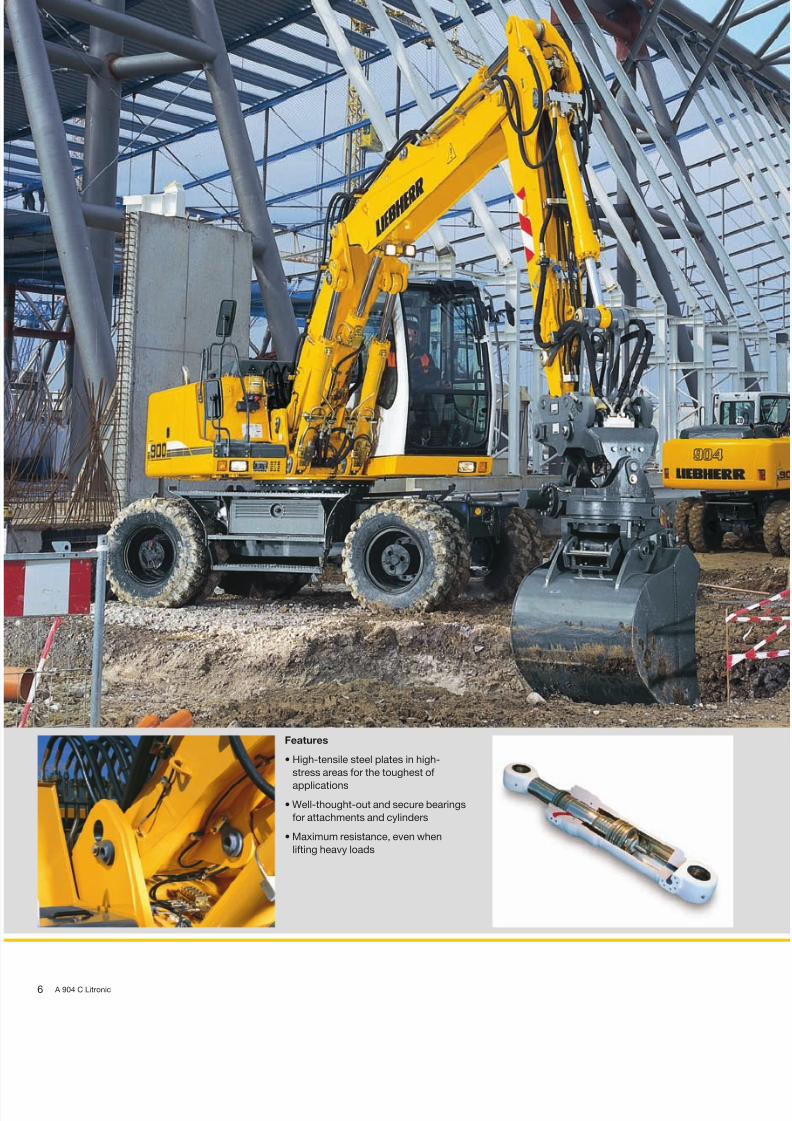
Features
• High-tensile steel plates in high-
stress areas for the toughest of
applications
• Well-thought-out and secure bearings
for attachments and cylinders
• Maximum resistance, even when
lifting heavy loads

8/10/2019 A904C-US-NTB02.08neu_7364-0
http://slidepdf.com/reader/full/a904c-us-ntb0208neu7364-0 7/24 A 904 C Litronic
Reliability
Liebherr construction machinery is proven all over the world every day on the mo
diverse of building sites. Many years of experience as the world’s largest manu
acturer of rubber-tyre excavators, continuous development and the introduction
the latest technology are evident in every machine, guaranteeing absolute safe
during applications. With its rugged design, and featuring Liebherr component
the A 904 C Litronic has been designed for extremely long life-expectancy.
Quality in detailLiebherr components Components such as engine, hydraulic cylinde
swing gear and electric parts have been speciadesigned, tested and manufactured by Liebherr fconstruction machinery. Parts including engines apumps for example, are already being synchronizwith each other as early as the construction phasyielding a constant standard of quality.
Functional safety Safety-orientated components, fitted as standard, alow high availability.
The operator can thus concentrate fully on the task hand, due to the integrated on-board electronics peforming a constant balancing of pre-defined set datFiltering of metallic filings by the magnetic rod, fittein the hydraulic system as standard, increases life-epectancy of the hydraulic components and the oil.
Rugged attachmentsWorking attachment The durable attachments have been designed for th
toughest of applications. All components are optimsed to the FEM methods and the hoist cylinders feture bearings on both sides.
Piping The hydraulic lines are arranged optimally to safguard against damage. The electric cabling is madwith high-grade materials, thus guaranteeing a reliabsupply to the consumer.
Liebherr hydraulic cylinders
• Specific size for each machine
• High-grade surface coating of
the piston rods
• All Liebherr cylinders feature special
long-life sealing systems
• Shock absorption at both sides
in the working cylinders
Functional safety
• Essential operating data is stored and can
be recalled at any time.
• Control and monitoring functions increase
functional safety of the machine.
• Four fixed working modes for output discharge
facilitate an effective and efficient operation:
– Eco-Mode: for high output at big fuel savings
– Power-Mode: for heavy-duty digging-and load
performance under severe conditions
– Lift-Mode: for precise handling of heavy loads
– Fine-Mode: for fine control at precision work

8/10/2019 A904C-US-NTB02.08neu_7364-0
http://slidepdf.com/reader/full/a904c-us-ntb0208neu7364-0 8/248 A 904 C Litronic
Large-sized cab
• Adjustable steering column
• Operator’s seat, adjustable in height and
can also be adapted to the individual weight
of the operator.
• Consoles with or without possibility
of horizontal adjustment.
• Large roof window
• Sun blinds

8/10/2019 A904C-US-NTB02.08neu_7364-0
http://slidepdf.com/reader/full/a904c-us-ntb0208neu7364-0 9/24 A 904 C Litronic
Comfort
The excavator operator is provided with an ergonomically-arranged working ar
within Liebherr hydraulic excavator cabs. All switches and functions are logica
laid out, and operator’s seat, steering column and consoles can be adjusted ind
vidually. Conditioning and concentration can thus be maintained throughout t
entire working day, guaranteeing constant, maximum productivity of the operato
Mobile comfortEasy access Wide steps, ergonomically-positioned handles a
adjustable steering column allow an easy access inthe Liebherr operator’s cab.
Optimum visibility A well-thought-out design of the uppercarriage, featring large glass panels and rounded edges, increaoverall visibility and guarantees a safe overview of tentire working area.
Pleasant surroundings Reduced engine speed together with elaborate souinsulation, as well as optimised hydraulic componenallow a comfortable noise level both inside and o
The noise level is comparable with that of a diesel c
Maintenance featuresEasy maintenance A central lubrication point for swing gear and ma
parts of the attachment.
Ease of operation A shut-off valve, fitted to the hydraulic tank as stadard, disconnects the system and guarantees ease maintenance to the hydraulic system.
Easy access Large maintenance flaps allow comfortable and saaccess to all maintenance points.
Fully-automatic air-conditioning system
• The air-conditioning system, fitted as
standard, offers the same comfort as that
of a regular car
• Two sensors for precise temperature
regulation
• Ventilation flaps are controlled via keys
• Reheat function for quick dehumidifying /
defrosting of the windshield
Storage compartment –
Everything has its place
• Sufficient storage space for a commer-
cially-approved cooler box behind theoperator’s seat
• Drinks holder and storage compart-
ment in operator’s cab
• Large storage box behind the
operator’s cab
• Two standard tool boxes in the
undercarriage

8/10/2019 A904C-US-NTB02.08neu_7364-0
http://slidepdf.com/reader/full/a904c-us-ntb0208neu7364-0 10/2410 A 904 C Litronic
Hydrostatic fan drive
• Accelerated warm-up period
• Guaranteed constant oil quality as a
result of constant oil temperature
• Increased life-expectancy of drive
components
• The fan only runs at the output re-
quired, thus conserving fuel and re-
ducing the noise level considerably

8/10/2019 A904C-US-NTB02.08neu_7364-0
http://slidepdf.com/reader/full/a904c-us-ntb0208neu7364-0 11/24 A 904 C Litronic
Economy
Liebherr offer a wide range of models, guaranteeing optimum suitability for eve
application. Easy access to components, as well as the proven service offer allow
maintenance tasks to be performed in the shortest of times, thus reducing oper
ting costs considerably.
Low operating costsLiebherr engine Maximum power of the engine is generated even wh
running at minimum speed. This allows the necessaoutput without limitation, whereby the torque whichavailable is ample for the level required, resulting hiproductivity with low consumption.
Automatic idle If no working or travel movements are being perfomed, the shiftable function reduces the engine speto idle, which in turn reduces fuel consumption aemission levels.
Liebherr Tool Control Available as an option, immediately after the changover of a hydraulic tool, the required pressure and
flow values can be selected with a push of a buttoUp to 10 combinations can be programmed. A tochangeover cannot be simpler and more time savin
Investment for the futureExtensive service offer Proven service offers assured by our service perso
nel trained directly at the manufacturing plants, aendorsed by our tight-knit network of dealers, proviservices in all required areas. Direct contact to Liebhis guaranteed via complete integration of all servipoints in our own Liebherr logistics system. Electronaccess to our global spare-parts management allowa 98% availability of spare-parts 24 hours a day.
High resale values Liebherr excavators are built with high-grade materiaand quality production to provide a long-term opertional life-span, thus guaranteeing maximum resavalues.
Service-orientated
• The semi-automatic central lubrica-
tion system fitted as standard saves
on time-consuming greasing
• Long filling intervals thanks to large
fuel tank
• Consistently high performance
thanks to series-production fuel
cooling system
Modular quick-change systemmade by Liebherr
• Likufix – connects all hydraulically mounte
tools without having to leave the opera-tor’s cab, maximum productivity due to to
change being performed in a matter of
seconds
• The suitable digging tool for every applica
tion. Your machine is a multi-functional too
carrier and will pay for itself very quickly
indeed.
• Mechanic and hydraulic Liebherr
quick-change adapter

8/10/2019 A904C-US-NTB02.08neu_7364-0
http://slidepdf.com/reader/full/a904c-us-ntb0208neu7364-0 12/2412 A 904 C Litronic
Technical Data
EngineRating per ISO 9249 ____________ 143 hp (105 kW) at 1800 rpmModel ______________________________ Liebherr D 934 S according to level IIIA / Tier 3Type ________________________________ 4 cylinder in-line
Bore/Stroke__________________ 4.8/5.4 inDisplacement________________ 390 in3
Engine operation ________________ 4-stroke dieselunit pump systemturbo-charged and after-cooledreduced emissions
Cooling system __________________ water-cooled and integrated motor oil cooler Air cleaner ________________________ dry-type air cleaner with pre-cleaner, primary and
safety elementsFuel tank __________________________ 93 galEngine idling ______________________ sensor controlledElectrical system
Voltage________________________ 24 VBatteries______________________ 2 x 110 Ah/12 V Alternator ____________________ three phase current 28 V/80 A
Swing DriveDrive ________________________________ Liebherr swash plate motor with torque control
and integrated brake valveTransmission ______________________ Liebherr compact planetary reduction gearSwing ring ________________________ Liebherr sealed single race ball bearing swing
ring, internal teeth
Swing speed ______________________ 0 – 9.0 rpmSwing torque ______________________ 33,928 lbf ftHolding brake ____________________ wet discs (spring applied – pressure released)Option ______________________________ pedal controlled positioning brake
Operator’s CabCab ________________________________ resiliently mounted, sound insulated, tinted
windows, front window stores overhead, doorwith sliding window
Operator’s seat __________________ fully adjustable, shock absorbing suspension,adjustable to operator’s weight and size,6-way adjustable Liebherr seat
Joysticks __________________________ integrated into adjustable seat consolesMonitoring ________________________ menu driven query of current operating condi-
tions via the LCD display. Automatic monitoring,
display, warning (acoustical and optical signal)and saving machine data, for example, engineoverheating, low engine oil pressure or lowhydraulic oil level
Air conditioning __________________ standard air conditioning, combined cooler/heater,additional dust filter in fresh air/recirculated
Noise emissionISO 6396 __________________________ LpA (inside cab) = 73 dB(A)2000/14/EC________________________ LWA (surround noise) = 100 dB(A)Sound level in correspondence with “Blue Angel” guidelines.
UndercarriageDrive ________________________________ variable flow swash plate motor with automatic
brake valveTransmission ______________________ oversized two speed power shift transmission
with additional creeper speed
Travel speed ______________________ 0 – 1.6 mph (creeper speed off road)0 – 3.1 mph (off road)0 – 5.6 mph (creeper speed on road)0 – 12.4 mph (road travel)0 – 18.6 mph Speeder (Option)
Axles________________________________ 88,185 lb excavator axles; automatic or operatorcontrolled front axle oscillation lock
Brakes ______________________________ steering and rigid axle with wet, maintenance-freemulti disc brakes with minimized backlash. Springapplied/pressure released parking brake integratedinto gear box
Stabilization ______________________ stabilizing blade (adjustable during travel fordozing)2-point outriggersstabilizing blade, front + 2 pt. outriggers, rear4-point outriggers
Option ______________________________ EW (extra wide gauge) undercarriage
AttachmentHydraulic cylinders ______________ Liebherr cylinders with special seal system.
Shock absorptionPivots ______________________________ sealed, low maintenanceLubrication ________________________ Liebherr semi-automatic central lubrication
systemBucket ____________________________ standard equipped with 17,637 lb safety hook for
liftingOption ______________________________ Liebherr quick change adapter
Hydraulic ControlsPower distribution ________________ via control valve with integrated safety valves,
simultaneous and independent operation of traveldrive, swing drive and work
Control type Attachment and swing ____ proportional via joystick leversTravel ________________________ proportional via foot pedal
Additional functions______________ via switch and/or proportional foot pedals
Hydraulic System
Hydraulic pump__________________
Liebherr, variable displacement, swash plate double pumpMax. flow ____________________ 2 x 50 gpmMax. hydr. pressure ________ 5,076 psi
Hydraulic pumpregulation and control __________ Liebherr-Synchronic-Comfort-system (LSC) with
electronic engine speed sensing regulation, pres-sure and flow compensation, load sensing andtorque controlled swing drive priority
Hydraulic tank capacity ________ 46 galHydraulic system capacity ______ max. 85 galFiltration____________________________ one main return filter with integrated partial micro
filtration (5 µm)Cooling system __________________ compact cooler, consisting of a water cooler,
sandwiched with hydraulic oil cooler, fuel coolerand after-cooler cores and hydrostatically drivenfan
Modes ______________________________ can also be adjusted by the operator to adjustengine and hydraulic performance to match jobconditions (Note: All modes provide full max.
power)LIFT __________________________ for precise lifting tasksFINE __________________________ for precision work at high speed i.e. gradingECO __________________________ for economic performancePOWER ______________________ for max. output
Super-Finish ______________________ additional operator adjustable work speed func-tion for further increased feathering. Applies to allmodes and all control functions
RPM adjustment__________________ step less adjustment of engine output via rpmTool Control (Option) ____________ ten pre-adjustable pump flows and pressures for
add on tools

8/10/2019 A904C-US-NTB02.08neu_7364-0
http://slidepdf.com/reader/full/a904c-us-ntb0208neu7364-0 13/24
Dimensions
A 904 C Litronic 1
ft in
A 8’ 4”
B 8’ 4”
B* 9’ ”
B1 12’ 1”B2 8’ 4”
B2* 9’ ”
C 10’ 4”
D 8’ 1”
E 8’ 3”
H 8’ 1”
I2 1’ 8”
I3 1’ 7”
J2 2’ 1”
J3 1’10”
K 4’ 1”
L 9’ ”
M 4’ 1”
Q 1’ 2”
T1 3’ 5”T2 4’ 2”
T3 5’ ”
T4 3’11”
U1 14’10”
U2 15’ 7”
U3 17’ 5”
U4 16’ 4”
* = EW-undercarriage
E = Tail radius
Tires 10.00-20
Stick Hydr. Adjustable Gooseneck BoomBoom 12’6” 17’5”stabil. 2 pt. blade 4 pt. stabil. 2 pt. blade 4 pt
blade outr. + 2 pt. outr. blade outr. + 2 pt. outr.
outr. outr.ft in ft in ft in ft in ft in ft in ft in ft in ft in
V 7’5” 20’ ” 19’10” 21’ 8” 19’10” 19’6” 19’ 4” 21’ 4” 20’2
8’ 19’ 8” 19’ 6” 21’ 4” 19’ 6” 19’ ” 18’10” 20’10” 19’8
8’8” 19’ 2” 19’ ” 20’12” 19’ ” 18’8” 18’ 6” 20’ 4” 19’2
10’ 16’ 5” 16’ 3” 19’ 8” 18’ 6” 16’5” 16’ 3” 18’ 4” 17’3
W 7’5” 10’ 6” 10’ 6” 10’ 6” 10’ 6” 10’4” 10’ 4” 10’ 4” 10’4
8’ 10’ 6” 10’ 6” 10’ 6” 10’ 6” 10’6” 10’ 6” 10’ 6” 10’6
8’8” 10’10” 10’10” 10’10” 10’10” 10’8” 10’ 8” 10’ 8” 10’8
10’ 10’ 2” 10’ 2” 10’12” 10’12” 10’2” 10’ 2” 10’ 8” 10’8
X 7’5” 29’ 8” 29’ 6” 31’ 4” 29’ 6” 29’8” 29’ 6” 31’ 4” 30’2
8’ 29’ 8” 29’ 6” 31’ 4” 29’ 6” 29’8” 29’ 6” 31’ 4” 30’2
8’8” 29’ 8” 29’ 6” 31’ 4” 29’ 6” 29’8” 29’ 6” 31’ 6” 30’4
10’ 29’ 6” 29’ 4” 31’ 4” 30’ 2” 29’6” 29’ 4” 31’ 6” 30’4
Dimensions are with attachment over steering axle
L
U1
V
X
W
D
E
K
H
C
B
Q
A
B1
M T1
T2
U2
J2I2
B
B2
T4
U4
T1 B
B1
J3 I3
T3
U3
T1 B
B2
B1

8/10/2019 A904C-US-NTB02.08neu_7364-0
http://slidepdf.com/reader/full/a904c-us-ntb0208neu7364-0 14/24
v
y
V
Y
Backhoe Attachment with Hydr. Adjustable Boom 12’6”
14 A 904 C Litronic
12
34
0 m123456789
0 ft51015202530
0
-1
-2
-3
-4
-5
0
-5
-10
-15
1
2
3
4
5
6
7
8
9
m
5
10
15
20
25
30
ft
10
-6-20
-710
1135
Digging Envelope with Quick Change Adapter 1 2 3 4
Stick length ft in 7’ 5” 8’ ” 8’8” 10’ ”
Max. digging depth ft in 19’ 2” 19’10” 20’6” 21’ 8”
Max. reach at ground level ft in 29’10” 30’ 6” 31’2” 31’10”
Max. dumping height ft in 22’ 6” 22’12” 23’5” 23’ 2”
Max. teeth height ft in 32’ 8” 33’ 2” 33’6” 32’12”
Digging Forces 1 2 3 4
Max. digging force lbf 21,267 20,053 18,974 17,130
lb 21,164 20,062 18,960 17,196
Max. breakout force lbf 31,159 31,159 31,159 31,159
lb 31,085 31,085 31,085 31,085
Max. breakout force with ripper bucket 35,273 lbf (35,274 lb)
Operating Weight
The operating weight includes the basic machine with 8 tires plus
spacer rings, hydr. adjustable boom 12’6”, stick 8’, quick change
adapter 48 and bucket 41.3”/0.92 yd3.
Undercarriage versions Weight
A 904 C litronic̀ with stabilizer blade 42,350 lb
A 904 C litronic̀ with 2 pt. outriggers 42,550 lb
A 904 C litronic̀ with stabilizer blade + 2 pt. outriggers 45,650 lb
A 904 C litronic̀ with 4 pt. outriggers 45,850 lb
A 904 C EW litronic̀ with stabilizer blade 42,800 lb
A 904 C EW litronic̀ with 2 pt. outriggers 42,800 lb
C u t t i n g w i d t h
C a p a c i t y
I S O 7 4 5 1 1 )
W e i g h t
Buckets Machine stability per ISO 10567* (75 % of tipping capacity)
Stabilizers Stabilizer 2 point Stabilizer blade 4 point EW stabilizers EW stabilizer EW 2 point
raised blade down outriggers + 2 pt. outr. outriggers raised blade down outriggers
down down down down
Stick length (ft in) Stick length (ft in) Stick length (ft in) Stick length (ft in) Stick length (ft in) Stick length (ft in) Stick length (ft in) Stick length (ft in)
7’5” 8’ 8’8” 10’ 7’5” 8’ 8’8” 10’ 7’5” 8’ 8’8” 10’ 7’5” 8’ 8’8” 10’ 7’5” 8’ 8’8” 10’ 7’5” 8’ 8’8” 10’ 7’5” 8’ 8’8” 10’ 7’5” 8’ 8’8” 10’
in yd3 lb
21.7” 0.39 0,970 Y Y Y Y Y Y Y Y Y Y Y Y Y Y Y Y Y Y Y Y Y Y Y Y Y Y Y Y Y Y Y Y
23.6” 0.46 1,543 Y Y Y Y Y Y Y Y Y Y Y Y Y Y Y Y Y Y Y Y Y Y Y Y Y Y Y Y Y Y Y Y
25.6” 0.52 1,036 Y Y Y Y Y Y Y Y Y Y Y Y Y Y Y Y Y Y Y Y Y Y Y Y Y Y Y Y Y Y Y Y
33.5” 0.72 1,190 Y Y Y Y Y Y Y Y Y Y Y Y Y Y Y Y Y Y Y Y Y Y Y Y Y Y Y Y Y Y Y Y
41.3” 0.92 1,367 Y V V y Y Y Y V Y Y Y Y Y Y Y Y Y Y Y Y Y Y Y V Y Y Y Y Y Y Y Y
49.2” 1.18 1,565 y y y v V V y y Y Y Y V Y Y Y Y Y Y Y Y V V y y Y V V y Y Y Y Y
55.1” 1.37 1,676 v v v v y y v v V V V y Y Y Y V Y Y Y V y y v v V y y y Y V V V
* Indicated loads are based on ISO 10567 and do not exceed 75 % of tipping or 87 % of hydraulic capacity, max. stick length without quick
change adapter, lifted 360° on firm with blocked oscillating axle1) comparable with SAE (heaped)
= ≤ 3,034 lb/yd3 max. material weight
= ≤ 2,528 lb/yd3 max. material weight
= ≤ 2,023 lb/yd3 max. material weight
= –

8/10/2019 A904C-US-NTB02.08neu_7364-0
http://slidepdf.com/reader/full/a904c-us-ntb0208neu7364-0 15/24
Lift Capacities with Hydr. Adjustable Boom 12’6”
A 904 C Litronic 1
Stick 7’5”10 ft 15 ft 20 ft 25 ft
ft Undercarriage ft inStabilizers raisedStabilizer blade down
2 pt. outriggers downBlade + 2 pt. down254 pt. outriggers down
Stabilizers raisedStabilizer blade down2 pt. outriggers downBlade + 2 pt. down
204 pt. outriggers down
Stabilizers raisedStabilizer blade down2 pt. outriggers downBlade + 2 pt. down
154 pt. outriggers down
Stabilizers raisedStabilizer blade down2 pt. outriggers downBlade + 2 pt. down
104 pt. outriggers down
Stabilizers raisedStabilizer blade down2 pt. outriggers downBlade + 2 pt. down
54 pt. outriggers down
Stabilizers raisedStabilizer blade down2 pt. outriggers downBlade + 2 pt. down
04 pt. outriggers down
Stabilizers raisedStabilizer blade down
2 pt. outriggers downBlade + 2 pt. down– 54 pt. outriggers down
Stabilizers raisedStabilizer blade down2 pt. outriggers downBlade + 2 pt. down
– 104 pt. outriggers down
Stabilizers raisedStabilizer blade down2 pt. outriggers downBlade + 2 pt. down
– 154 pt. outriggers down
7,700* 7,700*7,700* 7,700*
7,700* 7,700*7,700* 7,700*7,700* 7,700*
17’ 4”
6,800 10,600* 5,600 6,900*7,400 10,600* 6,100 6,900*8,800 10,600* 6,900* 6,900*
10,600* 10,600* 6,900* 6,900*10,600* 10,600* 6,900* 6,900*
21’10”
1 0, 50 0 1 4, 700 * 6 ,9 00 11 ,20 0 4, 40 0 6, 700 *1 1, 40 0 1 4, 700 * 7 ,5 00 12 ,70 0* 4, 90 0 6, 700 *1 3, 70 0 1 4, 700 * 9 ,0 00 12 ,70 0* 6, 00 0 6, 700 *14,700* 14,700* 11,200 12,700* 6 ,700 * 6 ,700 *14,700* 14,700* 12,700* 12,700* 6 ,700 * 6 ,700 *
24’ 6”
17,700 28,100* 10,000 16,800 6,800 11,100 4,200 7,400 3,800 6,800*19,600 28,100* 10,900 18,200* 7,400 14,100* 4,600 10,000* 4,200 6,800*24,300 28,100* 13,300 18,200* 8,900 14,100* 5,700 10,000* 5,300 6,800*28,100* 28,100* 16,700 18,200* 11,000 14,100* 7,400 10,000* 6,800* 6,800*28,100* 28,100* 18,200* 18,200* 12,800 14,100* 8,900 10,000* 6,800* 6,800*
25’10”
17,100 26,700* 9,800 16,600 6,600 11,100 4,000 7,300 3,600 6,60019,000 26,700* 10,800 21,200* 7,200 15,500* 4,400 12,500* 4,000 7,300*23,300 26,700* 12,900* 21,200* 8,600 15,500* 5,500 12,200 5,000 7,300*26,700* 26,700* 16,400 21,200* 11,100 15,500* 7,300 12,500* 6,600 7,300*26,700* 26,700* 19,300* 21,200* 12,700 15,500* 8,700 12,500* 7,300* 7,300*
26’ 2”
17,200 32,300 9,600 16,800* 6,000 10,500 3,700 7,000 3,600 6,80019,100 32,400* 10,500 22,300* 6,600 16,200* 4,200 11,300* 4,000 8,300*24,000* 32,400* 12,900 22,300* 8,100 16,200* 5,200 11,300* 5,000 8,300*31,100 32,400* 16,600 22,300* 10,500 16,200* 7,000 11,300* 6,800 8,300*32,400* 32,400* 19,500 22,300* 12,600 16,200* 8,500 11,300* 8,200 8,300*
25’ 6”
1 6, 20 0 3 3,2 00 9 ,1 00 1 6, 500 5 ,5 00 10 ,00 0 3, 90 0 7, 40018,100 36,300* 10,000 22,600* 6 ,100 16,500* 4 ,400 10,200*
23,100 36,300* 12,300 22,600* 7 ,500 16,500* 5 ,500 10,200*32,300 36,300* 16,300 22,600* 10,000 16,500* 7,400 10,200*36,300* 36,300* 20,000 22,600* 12,100 16,500* 9,000 10,200*
23’ 9”
1 6, 10 0 3 3,3 00 8, 30 0 1 5, 600 5, 100 9, 70 0 4, 90 0 9, 30017,900 37,700* 9,200 22,800* 5,700 13,000* 5 ,500 11,900*22,900 37,700* 11,500 22,800* 7 ,200 13,000* 6 ,900 11,900*32,100 37,700* 15,400 22,800* 9 ,600 13,000* 9 ,200 11,900*37,700* 37,700* 19,100 22,800* 11,700 13,000* 11,300 11,900*
20’ 6”
15,400 24,200* 11,600 18,200*17,200 24,200* 13,000 18,200*22,200 24,200* 16,400 18,200*24,200* 24,200* 18,200* 18,200*24,200* 24,200* 18,200* 18,200*
11’11”
Stick 8’10 ft 15 ft 20 ft 25 ft
ft Undercarriage ft iStabilizers raisedStabilizer blade down
2 pt. outriggers downBlade + 2 pt. down254 pt. outriggers down
Stabilizers raisedStabilizer blade down2 pt. outriggers downBlade + 2 pt. down
204 pt. outriggers down
Stabilizers raisedStabilizer blade down2 pt. outriggers downBlade + 2 pt. down
154 pt. outriggers down
Stabilizers raisedStabilizer blade down2 pt. outriggers downBlade + 2 pt. down
104 pt. outriggers down
Stabilizers raisedStabilizer blade down2 pt. outriggers downBlade + 2 pt. down
54 pt. outriggers down
Stabilizers raisedStabilizer blade down2 pt. outriggers downBlade + 2 pt. down
04 pt. outriggers down
Stabilizers raisedStabilizer blade down
2 pt. outriggers downBlade + 2 pt. down– 54 pt. outriggers down
Stabilizers raisedStabilizer blade down2 pt. outriggers downBlade + 2 pt. down
– 104 pt. outriggers down
Stabilizers raisedStabilizer blade down2 pt. outriggers downBlade + 2 pt. down
– 154 pt. outriggers down
7,000* 7,000*7,000* 7,000*
7,000* 7,000*7,000* 7,000*7,000* 7,000*
18’
6,900 10,400* 5,200 6,300*7,500 10,400* 5,800 6,300*8,900 10,400* 6,300* 6,300*
10,400* 10,400* 6,300* 6,300*10,400* 10,400* 6,300* 6,300*
22’
10,500 14,100* 6,800 11,300 4,200 6,700* 4,200 6,100*11,400 14,100* 7,500 12,300* 4,700 6,700* 4,600 6,100*13,700 14,100* 9,000 12,300* 5,800 6,700* 5,700 6,100*14,100* 14,100* 11,200 12,300* 6,700* 6,700* 6,100* 6,100*14,100* 14,100* 12,300* 12,300* 6,700* 6,700* 6,100* 6,100*
25’
18,000 27,900* 10,000 16,800* 6,600 11,000 4,200 7,500 3,600 6,200*20,000 27,900* 11,000 17,600* 7,200 13,800* 4,600 10,600* 4,000 6,200*24,400 27,900* 13,100 17,600* 8,700 13,800* 5,700 10,600* 5,000 6,200*27,900* 27,900* 16,700 17,600* 11,000 13,800* 7,500 10,600* 6,200* 6,200*27,900* 27,900* 17,600* 17,600* 12,800 13,800* 8,900 10,600* 6,200* 6,200*
26’
17,200 26,000* 9,500 16,400 6,700 11,000* 4,000 7,300 3,400 6,30019,100 26,000* 10,500 20,800* 7,300 15,200* 4,500 12,400* 3,800 6,600*23,300 26,000* 12,800 20,800* 8,600 15,200* 5,500 12,200 4,700 6,600*26,000* 26,000* 16,200 20,800* 11,000* 15,200* 7,300 12,400* 6,300 6,600*26,000* 26,000* 19,300* 20,800* 12,700 15,200* 8,700 12,400* 6,600* 6,600*
26’1
17,300 31,700* 9,600 16,500 6,100 10,600 3,800 7,000 3,400 6,50019,200 31,700* 10,500 22,200* 6,700 16,000* 4,200 12,500* 3,800 7,500*23,500 31,700* 12,900 22,200* 8,200 16,000* 5,300 11,900 4,800 7,500*31,200 31,700* 16,200 22,200* 10,600 16,000* 7,000 12,500* 6,500 7,500*31,700* 31,700* 19,100 22,200* 12,700 16,000* 8,500 12,500* 7,500* 7,500*
26’
1 6, 200 32 ,8 00 9 ,00 0 1 6, 50 0 5,5 00 1 0, 10 0 3 ,70 0 7, 10 018,100 35,800* 9 ,900 22,500* 6 ,100 16,300* 4 ,100 9 ,100*
23,100 35,800* 12,300 22,500* 7,600 16,300* 5 ,200 9 ,100 *32,000* 35,800* 16,200 22,500* 10,000 16,300* 7,100 9,100*35,800* 35,800* 20,000 22,500* 12,100 16,300* 8,600 9,100*
24’
1 5, 900 33 ,1 00 8, 30 0 1 5, 70 0 5 ,1 00 9, 60 0 4 ,60 0 8 ,70 017,800 37,300* 9,300 23,100* 5,700 14,200* 5 ,100 11,600*22,800 37,300* 11,500 23,100* 7 ,200 14,200* 6 ,400 11,600*31,900 37,300* 15,500 23,100* 9 ,600 14,200* 8 ,600 11,600*37,300* 37,300* 19,100 23,100* 11,700 14,200* 10,500 11,600*
21’
15,300 27,600* 8,400 14,000*17,100 27,600* 9,400 14,000*22,100 27,600* 11,800 14,000*27,600* 27,600* 14,000* 14,000*27,600* 27,600* 14,000* 14,000*
14’
Stick 8’8”10 ft 15 ft 20 ft 25 ft
ft Undercarriage ft inStabilizers raisedStabilizer blade down2 pt. outriggers downBlade + 2 pt. down
254 pt. outriggers down
Stabilizers raisedStabilizer blade down2 pt. outriggers downBlade + 2 pt. down
204 pt. outriggers down
Stabilizers raisedStabilizer blade down2 pt. outriggers downBlade + 2 pt. down
154 pt. outriggers down
Stabilizers raisedStabilizer blade down2 pt. outriggers downBlade + 2 pt. down
104 pt. outriggers down
Stabilizers raisedStabilizer blade down2 pt. outriggers downBlade + 2 pt. down
54 pt. outriggers down
Stabilizers raisedStabilizer blade down2 pt. outriggers downBlade + 2 pt. down
04 pt. outriggers down
Stabilizers raisedStabilizer blade down2 pt. outriggers downBlade + 2 pt. down
– 54 pt. outriggers down
Stabilizers raisedStabilizer blade down2 pt. outriggers downBlade + 2 pt. down
– 104 pt. outriggers down
Stabilizers raisedStabilizer blade down2 pt. outriggers downBlade + 2 pt. down
– 154 pt. outriggers down
6,400* 6,400*6,400* 6,400*6,400* 6,400*6,400* 6,400*6,400* 6,400*
19’ 3”
6,900 10,000* 4,900 5,800*6,900 10,000* 4,900 5,800*9,000 10,000* 5,800* 5,800*
10,000* 10,000* 5,800* 5,800*10,000* 10,000* 5,800* 5,800*
23’ 5”
10,500 12,700* 6,800 11,200 4,300 7,600 3,900 5,600*10,500 12,700* 6,800 11,200 4,300 7,600 3,900 5,600*12,700* 12,700* 8,900 11,900* 5,800 7,800* 5,400 5,600*12,700* 12,700* 11,200* 11,900* 7,600 7,800* 5,600* 5,600*12,700* 12,700* 11,900* 11,900* 7,800* 7,800* 5,600* 5,600*
25’10”
18,000 26,300* 9,900 16,900 6,700 10,900 4,300 7,500 3,400 5,700*18,000 26,300* 9,900 16,900 6,700 10,900 4,300 7,500 3,400 5,700*24,400 26,300* 13,200 17,000* 8,800 13,400* 5,800 10,800* 4,800 5,700*26,300* 26,300* 16,600 17,000* 10,900 13,400* 7,500 10,800* 5,700* 5,700*26,300* 26,300* 17,000* 17,000* 12,800 13,400* 8,900 10,800* 5,700* 5,700*
27’ 2”
17,300 25,300* 9,600 16,500 6,500 10,900 4,100 7,400 3,200 6,000*17,300 25,300* 9,600 16,500 6,500 10,900 4,100 7,400 3,200 6,000*23,400 25,300* 12,900 20,400* 8,700 15,000* 5,600 12,100 4,500 6,000*25,300* 25,300* 16,200 20,400* 10,800 15,000* 7,300 12,200* 6,000* 6,000*25,300* 25,300* 19,300 20,400* 12,600 15,000* 8,800 12,200* 6,000* 6,000*
27’ 6”
17,400 30,600* 9,600 16,500 6,300 10,700 3,800 7,100 3,200 6,20017,400 30,600* 9,600 16,500 6,300 10,700 3,800 7,100 3,200 6,20023,700 30,600* 13,000 22,000* 8,200 15,900* 5,300 11,900 4,600 6,800*30,600* 30,600* 16,300 22,000* 10,700 15,900* 7,100 12,500* 6,200 6,800*30,600* 30,600* 19,200 22,000* 12,700 15,900* 8,500 12,500* 6,800* 6,800*
26’10”
16,200 32,800 9,000 16,500 5,600 10,200 3,500 6,800 3,500 6,70016,200 32,800 9,000 16,500 5,600 10,200 3,500 6,800 3,500 6,70023,100 35,400* 12,300 22,300* 7,700 16,200* 5,000 8,900* 5,000 8,100*31,600 35,400* 16,200 22,300* 10,100 16,200* 6,800 8,900* 6,700 8,100*35,400* 35,400* 19,800 22,300* 12,100 16,200* 8,300 8,900* 8,100* 8,100*
25’ 2”
1 5, 80 0 3 3,0 00 8, 40 0 1 5, 800 5, 100 9, 60 0 4, 30 0 8, 1001 5, 80 0 3 3,0 00 8, 40 0 1 5, 800 5, 100 9, 60 0 4, 30 0 8, 10022,700 36,900* 11,600 23,000* 7 ,200 14,900* 6 ,000 11,000*31,800 36,900* 15,600 23,000* 9 ,600 14,900* 8 ,100 11,000*36,900* 36,900* 19,200 23,000* 11,700 14,900* 9,900 11,000*
22’ 2”
15,200 30,500* 8,000 15,200 6,900 11,900*15,200 30,500* 8,000 15,200 6,900 11,900*22,000 30,500* 11,100 15,400* 9,600 11,900*30,500* 30,500* 15,000 15,400* 11,900* 11,900*30,500* 30,500* 15,400* 15,400* 11,900* 11,900*
16’ 5”
Stick 10’10 ft 15 ft 20 ft 25 ft
ft Undercarriage ft iStabilizers raisedStabilizer blade down2 pt. outriggers downBlade + 2 pt. down
254 pt. outriggers down
Stabilizers raisedStabilizer blade down2 pt. outriggers downBlade + 2 pt. down
204 pt. outriggers down
Stabilizers raisedStabilizer blade down2 pt. outriggers downBlade + 2 pt. down
154 pt. outriggers down
Stabilizers raisedStabilizer blade down2 pt. outriggers downBlade + 2 pt. down
104 pt. outriggers down
Stabilizers raisedStabilizer blade down2 pt. outriggers downBlade + 2 pt. down
54 pt. outriggers down
Stabilizers raisedStabilizer blade down2 pt. outriggers downBlade + 2 pt. down
04 pt. outriggers down
Stabilizers raisedStabilizer blade down2 pt. outriggers downBlade + 2 pt. down
– 54 pt. outriggers down
Stabilizers raisedStabilizer blade down2 pt. outriggers downBlade + 2 pt. down
– 104 pt. outriggers down
Stabilizers raisedStabilizer blade down2 pt. outriggers downBlade + 2 pt. down
– 154 pt. outriggers down
6,800 7,100* 5,400* 5,400*7,100* 7,100* 5,400* 5,400*7,100* 7,100* 5,400* 5,400*7,100* 7,100* 5,400* 5,400*7,100* 7,100* 5,400* 5,400*
21’
7,000 9,100* 4,400 4,900*7,600 9,100* 4,900 4,900*9,000 9,100* 4,900* 4,900*9,100* 9,100* 4,900* 4,900*9,100* 9,100* 4,900* 4,900*
24’1
6,800 10,400* 4,500 7,700 3,600 4,700*7,400 10,400* 4,900 8,300* 4,000 4,700*9,000 10,400* 6,000 8,300* 4,700* 4,700*
10,400* 10,400* 7,700 8,300* 4,700* 4,700*10,400* 10,400* 8,300* 8,300* 4,700* 4,700*
27’
18,200 23,200* 10,100 15,800* 6,600 10,900 4,400 7,700 3,100 4,800*20,200 23,200* 11,100 15,800* 7,200 12,700* 4,900 10,400* 3,500 4,800*23,200* 23,200* 13,200* 15,800* 8,700 12,700* 5,900 10,400* 4,400 4,800*23,200* 23,200* 15,800* 15,800* 10,800* 12,700* 7,600 10,400* 4,800* 4,800*23,200* 23,200* 15,800* 15,800* 12,700* 12,700* 9,100 10,400* 4,800* 4,800*
28’
17,100 27,700* 9,400 16,400 6,500 10,700 4,200 7,500 2,900 5,100*19,000 27,700* 10,400 19,500* 7,100 14,400* 4,700 11,800* 3,300 5,100*23,500 27,700* 12,700 19,500* 8,600 14,400* 5,700 11,800* 4,200 5,100*27,700* 27,700* 16,100 19,500* 10,700 14,400* 7,400 11,800* 5,100* 5,100*27,700* 27,700* 19,200 19,500* 12,500 14,400* 8,900 11,800* 5,100* 5,100*
28’
17,000 28,600* 9,400 16,200 6,300 10,900 3,900 7,200 2,900 5,600*19,000 28,600* 10,400 21,700* 6,900 15,600* 4,400 12,300* 3,300 5,600*23,300 28,600* 12,700 21,700* 8,400 15,600* 5,400 12,000 4,200 5,600*28,600* 28,600* 16,000 21,700* 10,800 15,600* 7,200 12,300* 5,600* 5,600*28,600* 28,600* 19,000 21,700* 12,500 15,600* 8,600 12,300* 5,600* 5,600*
28’
16,300 32,200 9,000 16,500 5,800 10,200 3,600 6,900 3,100 6,10018,200 34,200* 9,900 22,100* 6,400 15,900* 4,000 12,000* 3,500 6,600*23,200 34,200* 12,300 22,100* 7,900 15,900* 5,100 11,700 4,500 6,600*31,000 34,200* 16,300 22,100* 10,200 15,900* 6,900 12,000* 6,100 6,600*34,200* 34,200* 19,300 22,100* 12,300 15,900* 8,300 12,000* 6,600* 6,600*
26’
1 5, 700 32 ,9 00 8, 70 0 1 6, 10 0 5 ,2 00 9, 70 0 3 ,70 0 7 ,20 017,600 36,400* 9 ,600 22,700* 5 ,800 15,800* 4 ,200 8 ,600*22,500 36,400* 11,900 22,700* 7,200 15,800* 5 ,300 8 ,600 *31,700 36,400* 15,800 22,700* 9,700 15,800* 7 ,200 8 ,600 *36,400* 36,400* 19,200 22,700* 11,700 15,800* 8,600* 8,600*
23’
15,300 32,400 7,900 15,200 5,300 10,100*17,200 34,700* 8,800 19,200* 5,900 10,100*22,100 34,700* 11,100 19,200* 7,500 10,100*31,200 34,700* 15,000 19,200* 10,100 10,100*34,700* 34,700* 18,600 19,200* 10,100* 10,100*
19’
Height Can be slewed through 360° In longitudinal position of undercarriage Max. reach * Limited by hydr. capacity
The lift capacities on the load hook of the Liebherr quick-change adapter 48 without grab attachment are stated in pounds (lb) and are valid on a firm, level supporting surface with
blocked oscillating axle. These capacities can be slewed through 360° with the undercarriage in the transverse position. Capacities in the longitudinal position of the undercarriage
(+/– 15°) are specified over the steering axle with the stabilizers raised and over the rigid axle with the stabilizers down. The values apply when the adjusting cylinder is in the optim
position. Indicated loads comply with the ISO 10567 standard and do not exceed 75 % of tipping or 87 % of hydraulic capacity, or are limited by the permissible load of the load
hook on the quick-change adapter (max. 26,455 lb). Without the quick-change adapter, lift capacities will increase by up to 498 lb.

8/10/2019 A904C-US-NTB02.08neu_7364-0
http://slidepdf.com/reader/full/a904c-us-ntb0208neu7364-0 16/24
Lift Capacities with Hydr. Adjustable Boom 12’6” EW-Undercarriage
16 A 904 C Litronic
Stick 7’5”10 ft 15 ft 20 ft 25 ft
ft Undercarriage ft in
Stabilizers raised
Stabilizer blade down25 2 pt. outriggers down
Stabilizers raisedStabilizer blade down202 pt. outriggers down
Stabilizers raisedStabilizer blade down152 pt. outriggers down
Stabilizers raisedStabilizer blade down102 pt. outriggers down
Stabilizers raisedStabilizer blade down52 pt. outriggers down
Stabilizers raisedStabilizer blade down02 pt. outriggers down
Stabilizers raised
Stabilizer blade down– 5 2 pt. outriggers down
Stabilizers raisedStabilizer blade down– 102 pt. outriggers down
Stabilizers raisedStabilizer blade down– 152 pt. outriggers down
7,700* 7,700*
7,700* 7,700*7,700* 7,700*17’ 4”
7,400 10,600* 6,100 6,900*8,200 10,600* 6,800 6,900*9,200 10,600* 6,900* 6,900*
21’10”
1 1, 400 14 ,7 00 * 7 ,50 0 1 1, 30 0 4, 900 6 ,7 00 *1 2, 700 14 ,7 00 * 8 ,30 0 1 2, 70 0* 5, 400 6, 700 *1 4, 300 14 ,7 00 * 9 ,40 0 1 2, 70 0* 6, 300 6, 700 *
24’ 6”
19,600 28,100* 10,900 16,900 7,400 11,200 4,600 7,500 4,200 6,800*22,200 28,100* 12,200 18,200* 8,200 14,100* 5,200 10,000* 4,800 6,800*25,400 28,100* 13,700 18,200* 9,200 14,100* 6,000 10,000* 5,500 6,800*
25’10”
19,000 26,700* 10,800 16,700 7,200 11,200* 4,400 7,300 4,000 6,70021,700 26,700* 12,000 21,200* 7,900 15,500* 5,000 12,500* 4,500 7,300*24,800 26,700* 13,400 21,200* 9,000 15,500* 5,800 12,200* 5,200 7,300*
26’ 2”
19,100 32,400* 10,500 16,800* 6,700 10,600 4,200 7,100 4,000 6,80021,700 32,400* 11,800 22,300* 7,400 16,200* 4,700 11,300* 4,600 8,300*24,900 32,400* 13,500 22,300* 8,500 16,200* 5,500 11,300* 5,300 8,300*
25’ 6”
1 8,1 00 3 3, 40 0 1 0, 000 16 ,6 00 6 , 10 0 1 0, 10 0 4, 400 7 , 500
20,700 36,300* 11,200 22,600* 6 ,800 16,500* 5 ,000 10,200*24,600 36,300* 13,000 22,600* 7 ,900 16,500* 5 ,900 10,200*23’ 9”
1 7,9 00 3 3, 60 0 9, 200 15 ,8 00 5, 70 0 9 ,80 0 5, 500 9, 40020,500 37,700* 10,400 22,800* 6 ,500 13,000* 6 ,200 11,900*24,400 37,700* 12,100 22,800* 7 ,600 13,000* 7 ,300 11,900*
20’ 6”
17,200 24,200* 13,000 18,200*19,800 24,200* 14,800 18,200*23,600 24,200* 17,400 18,200*
11’11”
Stick 8’10 ft 15 ft 20 ft 25 ft
ft Undercarriage ft in
Stabilizers raised
Stabilizer blade down25 2 pt. outriggers down
Stabilizers raisedStabilizer blade down202 pt. outriggers down
Stabilizers raisedStabilizer blade down152 pt. outriggers down
Stabilizers raisedStabilizer blade down102 pt. outriggers down
Stabilizers raisedStabilizer blade down52 pt. outriggers down
Stabilizers raisedStabilizer blade down02 pt. outriggers down
Stabilizers raised
Stabilizer blade down– 5 2 pt. outriggers down
Stabilizers raisedStabilizer blade down– 102 pt. outriggers down
Stabilizers raisedStabilizer blade down– 152 pt. outriggers down
7,000* 7,000*
7,000* 7,000*7,000* 7,000*18’ 4”
7,500 10,400* 5,800 6,300*8,200 10,400* 6,300* 6,300*9,300 10,400* 6,300* 6,300*
22’ 8”
11,400 14,100* 7,500 11,300* 4,700 6,700* 4,600 6,100*12,700 14,100* 8,300 12,300* 5,300 6,700* 5,200 6,100*14,100* 14,100* 9,300 12,300* 6,100 6,700* 6,000 6,100*
25’ 2”
20,000 27,900* 11,000 16,900 7,200 11,100 4,700 7,600 4,000 6,200*21,900 27,900* 12,200 17,600* 8,000 13,800* 5,200 10,600* 4,500 6,200*25,500 27,900* 13,700 17,600* 9,200 13,800* 6,000 10,600* 5,300 6,200*
26’ 6”
19,100 26,000* 10,500 16,500 7,300 11,000* 4,500 7,400 3,800 6,40021,700 26,000* 11,700 20,800* 8,000 15,200* 5,000 12,400* 4,300 6,600*24,800 26,000* 13,500 20,800* 9,100 15,200* 5,800 12,200 5,000 6,600*
26’10”
19,200 31,700* 10,600 16,600 6,700 10,700 4,200 7,100 3,800 6,50021,800 31,700* 11,800 22,200* 7,500 16,000* 4,800 12,500* 4,300 7,500*25,000 31,700* 13,600 22,200* 8,600 16,000* 5,600 12,000 5,100 7,500*
26’ 2”
18 ,1 00 33 ,10 0 9, 90 0 1 6,6 00 6 ,1 00 1 0, 200 4 ,20 0 7,1 00
20,600 35,800* 11,200 22,500* 6,900 16,300* 4 ,700 9 ,100 *24,600 35,800* 12,900 22,500* 8,000 16,300* 5 ,500 9 ,100 *24’ 5”
17 ,8 00 33 ,40 0 9 ,30 0 1 5,8 00 5, 70 0 9, 700 5 ,10 0 8 ,8 0020,400 37,300* 10,500 23,100* 6 ,500 14,200* 5 ,800 11,600*24,300 37,300* 12,200 23,100* 7 ,600 14,200* 6 ,800 11,600*
21’ 4”
17,100 27,600* 9,400 14,000*19,700 27,600* 10,600 14,000*23,500 27,600* 12,500 14,000*
14’ 6”
Stick 8’8”10 ft 15 ft 20 ft 25 ft
ft Undercarriage ft in
Stabilizers raisedStabilizer blade down252 pt. outriggers down
Stabilizers raisedStabilizer blade down202 pt. outriggers down
Stabilizers raisedStabilizer blade down152 pt. outriggers down
Stabilizers raisedStabilizer blade down102 pt. outriggers down
Stabilizers raisedStabilizer blade down52 pt. outriggers down
Stabilizers raisedStabilizer blade down02 pt. outriggers down
Stabilizers raisedStabilizer blade down– 52 pt. outriggers down
Stabilizers raisedStabilizer blade down– 102 pt. outriggers down
Stabilizers raisedStabilizer blade down– 152 pt. outriggers down
6,400* 6,400*6,400* 6,400*6,400* 6,400*
19’ 3”
7,600 10,000* 5,400 5,800*8,300 10,000* 5,800* 5,800*9,400 10,000* 5,800* 5,800*
23’ 5”
11,400 12,700* 7,400 11,300 4,800 7,700 4,400 5,600*12,700 12,700* 8,200 11,900* 5,300 7,800* 4,900 5,600*12,700* 12,700* 9,300 11,900* 6,100 7,800* 5,600* 5,600*
25’10”
20,000 26,300* 10,800 17,000* 7,300 11,000 4,700 7,600 3,800 5,700*22,300 26,300* 12,100 17,000* 8,100 13,400* 5,300 10,800* 4,300 5,700*25,600 26,300* 13,700* 17,000* 9,100 13,400* 6,100 10,800* 5,100 5,700*
27’ 2”
19,200 25,300* 10,500 16,600 7,200 11,000 4,500 7,400 3,600 6,000*21,000 25,300* 11,800 20,400* 8,000 15,000* 5,100 12,200* 4,100 6,000*24,900 25,300* 13,300* 20,400* 9,100 15,000* 5,900 12,200* 4,800 6,000*
27’ 6”
19,300 30,600* 10,600 16,600 6,900 10,800 4,200 7,100 3,600 6,20021,600 30,600* 11,800 22,000* 7,700 15,900* 4,800 12,500* 4,100 6,800*24,500* 30,600* 13,400 22,000* 8,600 15,900* 5,600 12,000 4,800 6,800*
26’10”
18,100 32,800* 9,900 16,600 6,200 10,200* 4,000 6,900 3,900 6,80020,600 35,400* 11,200 22,300* 7,000 16,200* 4,500 8,900* 4,500 8,100*24,600 35,400* 12,900 22,300* 8,100 16,200* 5,300 8,900* 5,300 8,100*
25’ 2”
1 7,7 00 3 3, 30 0 9, 300 15 ,9 00 5, 70 0 9 ,70 0 4, 800 8, 20020,200 36,900* 10,500 23,000* 6 ,500 14,900* 5 ,400 11,000*24,100 36,900* 12,300 23,000* 7 ,600 14,900* 6 ,400 11,000*
22’ 2”
17,100 30,500* 8,900 15,400 7,700 11,900*19,600 30,500* 10,100 15,400* 8,700 11,900*23,500 30,500* 11,800 15,400* 10,200 11,900*
16’ 5”
Stick 10’10 ft 15 ft 20 ft 25 ft
ft Undercarriage ft in
Stabilizers raisedStabilizer blade down252 pt. outriggers down
Stabilizers raisedStabilizer blade down202 pt. outriggers down
Stabilizers raisedStabilizer blade down152 pt. outriggers down
Stabilizers raisedStabilizer blade down102 pt. outriggers down
Stabilizers raisedStabilizer blade down52 pt. outriggers down
Stabilizers raisedStabilizer blade down02 pt. outriggers down
Stabilizers raisedStabilizer blade down– 52 pt. outriggers down
Stabilizers raisedStabilizer blade down– 102 pt. outriggers down
Stabilizers raisedStabilizer blade down– 152 pt. outriggers down
7,100* 7,100* 5,400* 5,400*7,100* 7,100* 5,400* 5,400*7,100* 7,100* 5,400* 5,400*
21’ 1”
7,600 9,100* 4,900 4,900*8,400 9,100* 4,900* 4,900*9,100* 9,100* 4,900* 4,900*
24’11”
7,400 10,400* 4,900 7,800 4,000 4,700*8,200 10,400* 5,500 8,300* 4,500 4,700*9,300 10,400* 6,300 8,300* 4,700* 4,700*
27’ 3”
20,200 23,200* 11,100 15,800* 7,200 11,100 4,900 7,700 3,500 4,800*22,500 23,200* 12,300* 15,800* 8,000 12,700* 5,400 10,400* 4,000 4,800*23,200* 23,200* 13,800 15,800* 9,000 12,700* 6,200 10,400* 4,700 4,800*
28’ 6”
19,000 27,700* 10,400 16,500 7,100 10,800 4,700 7,500 3,300 5,100*21,600 27,700* 11,600 19,500* 7,900 14,400* 5,300* 11,800* 3,800 5,100*24,700* 27,700* 13,400 19,500* 9,000 14,400* 6,000 11,800* 4,400 5,100*
28’ 9”
18,900 28,600* 10,400 16,300 6,900 10,900 4,400 7,200 3,300 5,600*21,200* 28,600* 11,600 21,700* 7,700 15,600* 4,900 12,300* 3,800 5,600*24,800 28,600* 13,300* 21,700* 8,800 15,600* 5,700 12,100 4,400 5,600*
28’ 2”
18,200 32,500 10,000 16,700 6,400 10,300 4,000 6,900 3,500 6,20020,700 34,200* 11,200 22,100* 7,200 15,900* 4,600 12,000* 4,100 6,600*24,700 34,200* 12,900 22,100* 8,300 15,900* 5,400 11,800 4,800 6,600*
26’ 6”
17 ,6 00 33 ,20 0 9 ,60 0 1 6,2 00 5, 80 0 9, 800 4 ,20 0 7 ,3 0020,100 36,400* 10,800 22,700* 6,500 15,800* 4 ,800 8 ,600 *24,000 36,400* 12,500 22,700* 7,600 15,800* 5 ,700 8 ,600 *
23’ 9”
17,200 32,700 8,800 15,400 5,900 10,100*19,700 34,700* 10,000 19,200* 6,700 10,100*23,600 34,700* 11,700 19,200* 7,900 10,100*
19’ 2”
Height Can be slewed through 360° In longitudinal position of undercarriage Max. reach * Limited by hydr. capacity
The lift capacities on the load hook of the Liebherr quick-change adapter 48 without grab attachment are stated in pounds (lb) and are valid on a firm, level supporting surface with
blocked oscillating axle. These capacities can be slewed through 360° with the undercarriage in the transverse position. Capacities in the longitudinal position of the undercarriage
(+/– 15°) are specified over the steering axle with the stabilizers raised and over the rigid axle with the stabilizers down. The values apply when the adjusting cylinder is in the optimal
position. Indicated loads comply with the ISO 10567 standard and do not exceed 75 % of tipping or 87 % of hydraulic capacity, or are limited by the permissible load of the load
hook on the quick-change adapter (max. 26,455 lb). Without the quick-change adapter, lift capacities will increase by up to 498 lb.

8/10/2019 A904C-US-NTB02.08neu_7364-0
http://slidepdf.com/reader/full/a904c-us-ntb0208neu7364-0 17/24
v
y
V
Y
A 904 C Litronic 1
Backhoe Attachment with Gooseneck Boom 17’5”
123
4
0 m123456789
0 ft51015202530
0
-1
-2
-3
-4
-5
0
-5
-10
-15
1
2
3
4
5
6
7
8
9
m
5
10
15
20
25
30
ft
10
-6-20
-710
Digging Envelope with Quick Change Adapter 1 2 3 4
Stick length ft in 7’5” 8’ ” 8’8” 10’
Max. digging depth ft in 19’ ” 19’ 8” 20’4” 21’ 8
Max. reach at ground level ft in 29’8” 30’ 4” 31’ ” 31’ 8
Max. dumping height ft in 20’6” 20’10” 21’4” 20’ 6
Max. teeth height ft in 30’4” 30’ 8” 31’2” 29’10
Operating Weight
The operating weight includes the basic machine with 8 tires plus
spacer rings, gooseneck boom 17’5”, stick 8’, quick change adapter
48 and bucket 41.3”/0.92 yd3.
Undercarriage versions Weigh
A 904 C litronic̀ with stabilizer blade 41,200 lb
A 904 C litronic̀ with 2 pt. outriggers 41,200 lb
A 904 C litronic̀ with stabilizer blade + 2 pt. outriggers 44,550 lb
A 904 C litronic̀ with 4 pt. outriggers 44,750 lb
A 904 C EW litronic̀ with stabilizer blade 41,650 lb
A 904 C EW litronic̀ with 2 pt. outriggers 41,450 lb
Digging Forces 1 2 3 4
Max. digging force lbf 21,267 20,053 18,974 17,130
lb 21,164 20,062 18,960 17,196
Max. breakout force lbf 31,159 31,159 31,159 31,159
lb 31,085 31,085 31,085 31,085
Max. breakout force with ripper bucket 35,273 lbf (35,274 lb
C u t t i n g w i d t h
C a p a c i t y
I S O 7 4 5 1 1 )
W e i g h t
Buckets Machine stability per ISO 10567* (75 % of tipping capacity)
Stabilizers Stabilizer 2 point Stabilizer blade 4 point EW stabilizers EW stabilizer EW 2 point
raised blade down outriggers + 2 pt. outr. outriggers raised blade down outriggers
down down down down
Stick length (ft in) Stick length (ft in) Stick length (ft in) Stick length (ft in) Stick length (ft in) Stick length (ft in) Stick length (ft in) Stick length (ft in
7’5” 8’ 8’8” 10’ 7’5” 8’ 8’8” 10’ 7’5” 8’ 8’8” 10’ 7’5” 8’ 8’8” 10’ 7’5” 8’ 8’8” 10’ 7’5” 8’ 8’8” 10’ 7’5” 8’ 8’8” 10’ 7’5” 8’ 8’8” 10
in yd3 lb
21.7” 0.39 0,970 Y Y Y Y Y Y Y Y Y Y Y Y Y Y Y Y Y Y Y Y Y Y Y Y Y Y Y Y Y Y Y Y
23.6” 0.46 1,543 Y Y Y Y Y Y Y Y Y Y Y Y Y Y Y Y Y Y Y Y Y Y Y Y Y Y Y Y Y Y Y Y
25.6” 0.52 1,036 Y Y Y Y Y Y Y Y Y Y Y Y Y Y Y Y Y Y Y Y Y Y Y Y Y Y Y Y Y Y Y Y
33.5” 0.72 1,190 Y Y Y Y Y Y Y Y Y Y Y Y Y Y Y Y Y Y Y Y Y Y Y Y Y Y Y Y Y Y Y Y
41.3” 0.92 1,367 Y Y V V Y Y Y Y Y Y Y Y Y Y Y Y Y Y Y Y Y Y Y V Y Y Y Y Y Y Y Y
49.2” 1.18 1,565 y y y v V V y y Y Y Y V Y Y Y V Y Y Y V V V y y Y Y V V Y Y Y V
55.1” 1.37 1,676 y v v v y y y v Y V V y Y Y V y Y Y V y y y y v V V y y Y Y V y
* Indicated loads are based on ISO 10567 and do not exceed 75 % of tipping or 87 % of hydraulic capacity, max. stick length without quick
change adapter, lifted 360° on firm with blocked oscillating axle1) comparable with SAE (heaped)
= ≤ 3,034 lb/yd3 max. material weight
= ≤ 2,528 lb/yd3 max. material weight
= ≤ 2,023 lb/yd3 max. material weight
= –

8/10/2019 A904C-US-NTB02.08neu_7364-0
http://slidepdf.com/reader/full/a904c-us-ntb0208neu7364-0 18/24
Lift Capacities with Gooseneck Boom 17’5”
18 A 904 C Litronic
Stick 7’5”10 ft 15 ft 20 ft 25 ft
ft Undercarriage ft inStabilizers raisedStabilizer blade down
2 pt. outriggers downBlade + 2 pt. down254 pt. outriggers down
Stabilizers raisedStabilizer blade down2 pt. outriggers downBlade + 2 pt. down
204 pt. outriggers down
Stabilizers raisedStabilizer blade down2 pt. outriggers downBlade + 2 pt. down
154 pt. outriggers down
Stabilizers raisedStabilizer blade down2 pt. outriggers downBlade + 2 pt. down
104 pt. outriggers down
Stabilizers raisedStabilizer blade down2 pt. outriggers downBlade + 2 pt. down
54 pt. outriggers down
Stabilizers raisedStabilizer blade down2 pt. outriggers downBlade + 2 pt. down
04 pt. outriggers down
Stabilizers raisedStabilizer blade down
2 pt. outriggers downBlade + 2 pt. down– 54 pt. outriggers down
Stabilizers raisedStabilizer blade down2 pt. outriggers downBlade + 2 pt. down
– 104 pt. outriggers down
Stabilizers raisedStabilizer blade down2 pt. outriggers downBlade + 2 pt. down
– 154 pt. outriggers down
6,500* 6,500*6,500* 6,500*
6,500* 6,500*6,500* 6,500*6,500* 6,500*
17’1”
6,700 9,500* 5,800 5,900*7,300 9,500* 5,900* 5,900*8,700 9,500* 5,900* 5,900*9,500* 9,500* 5,900* 5,900*9,500* 9,500* 5,900* 5,900*
21’8”
6,400 10,900* 4,500 5,700*7,000 10,900* 5,000 5,700*8,500 10,900* 5,700* 5,700*
10,900* 10,900* 5,700* 5,700*10,900* 10,900* 5,700* 5,700*
24’4”
16,200 26,400* 9,200 15,900* 6,000 10,500 4,100 7,400 3,900 6,000*18,000 26,400* 10,100 15,900* 6,600 12,700* 4,600 8,600* 4,400 6,000*23,000 26,400* 12,400 15,900* 8,000 12,700* 5,600 8,600* 5,400 6,000*26,400* 26,400* 15,900* 15,900* 10,500 12,700* 7,400 8,600* 6,000* 6,000*26,400* 26,400* 15,900* 15,900* 12,600 12,700* 8,600* 8,600* 6,000* 6,000*
25’8”
8,200 15,400 5,500 10,000 3,900 7,100 3,700 6,500*9,100 19,900* 6,100 14,600* 4,400 11,100* 4,100 6,500*
11,400 19,900* 7,600 14,600* 5,400 11,100* 5,100 6,500*15,200 19,900* 10,000 14,600* 7,200 11,100* 6,500* 6,500*18,700 19,900* 12,000 14,600* 8,600 11,100* 6,500* 6,500*
26’ ”
13,600* 13,600* 7,700 14,700 5,200 9,600 3,800 7,000 3,700 6,90013,600* 13,600* 8,500 22,100* 5,800 15,900* 4,200 9,400* 4,100 7,500*13,600* 13,600* 10,800 22,100* 7,200 15,900* 5,300 9,400* 5,200 7,500*13,600* 13,600* 14,500 22,100* 9,600 15,900* 7,000 9,400* 6,900 7,500*13,600* 13,600* 18,100 22,100* 11,600 15,900* 8,400 9,400* 7,500* 7,500*
25’4”
1 3,7 00 2 2, 00 0* 7, 500 14 ,5 00 5 ,10 0 9, 50 0 4, 100 7 ,6 0015,500 22,000* 8 ,400 22,400* 5 ,600 16,300* 4 ,500 9 ,600*
20,200 22,000* 10,600 22,400* 7,100 16,300* 5 ,700 9 ,600 *22,000* 22,000* 14,400 22,400* 9,400 16,300* 7 ,600 9 ,600 *22,000* 22,000* 17,900 22,400* 11,500 16,300* 9,100 9,600*
23’6”
1 4,1 00 3 0, 30 0* 7, 600 14 ,7 00 5 ,20 0 9, 60 0 5, 100 9 ,4 0015,900 30,300* 8,500 20,600* 5,800 14,700* 5 ,700 14,400*20,600 30,300* 10,700 20,600* 7 ,200 14,700* 7 ,100 14,400*29,300 30,300* 14,500 20,600* 9 ,600 14,700* 9 ,400 14,400*30,300* 30,300* 18,000 20,600* 11,600 14,700* 11,400 14,400*
20’3”
8,500 15,500*9,400 15,500*
11,800 15,500*15,500* 15,500*15,500* 15,500*
14’7”
Stick 8’10 ft 15 ft 20 ft 25 ft
ft Undercarriage ft inStabilizers raisedStabilizer blade down
2 pt. outriggers downBlade + 2 pt. down254 pt. outriggers down
Stabilizers raisedStabilizer blade down2 pt. outriggers downBlade + 2 pt. down
204 pt. outriggers down
Stabilizers raisedStabilizer blade down2 pt. outriggers downBlade + 2 pt. down
154 pt. outriggers down
Stabilizers raisedStabilizer blade down2 pt. outriggers downBlade + 2 pt. down
104 pt. outriggers down
Stabilizers raisedStabilizer blade down2 pt. outriggers downBlade + 2 pt. down
54 pt. outriggers down
Stabilizers raisedStabilizer blade down2 pt. outriggers downBlade + 2 pt. down
04 pt. outriggers down
Stabilizers raisedStabilizer blade down
2 pt. outriggers downBlade + 2 pt. down– 54 pt. outriggers down
Stabilizers raisedStabilizer blade down2 pt. outriggers downBlade + 2 pt. down
– 104 pt. outriggers down
Stabilizers raisedStabilizer blade down2 pt. outriggers downBlade + 2 pt. down
– 154 pt. outriggers down
5,900* 5,900*5,900* 5,900*
5,900* 5,900*5,900* 5,900*5,900* 5,900*
18’ ”
6,700 9,600* 5,300* 5,300*7,300 9,600* 5,300* 5,300*8,800 9,600* 5,300* 5,300*9,600* 9,600* 5,300* 5,300*9,600* 9,600* 5,300* 5,300*
22’5”
6,500 10,500* 4,300 5,200*7,000 10,500* 4,700 5,200*8,500 10,500* 5,200* 5,200*
10,500* 10,500* 5,200* 5,200*10,500* 10,500* 5,200* 5,200*
25’ ”
16,600 24,500* 9,300 15,300* 6,000 10,500 4,100 7,400 3,700 5,400*18,500 24,500* 10,200 15,300* 6,600 12,200* 4,600 9,500* 4,200 5,400*23,400 24,500* 12,500 15,300* 8,000 12,200* 5,600 9,500* 5,100 5,400*24,500* 24,500* 15,300* 15,300* 10,500 12,200* 7,400 9,500* 5,400* 5,400*24,500* 24,500* 15,300* 15,300* 12,200* 12,200* 8,800 9,500* 5,400* 5,400*
26’4”
8,200 15,400 5,500 10,000 3,900 7,100 3,500 5,900*9,100 19,400* 6,100 14,200* 4,300 11,900* 3,900 5,900*
11,400 19,400* 7,500 14,200* 5,400 11,900* 4,900 5,900*15,200 19,400* 9,900 14,200* 7,100 11,900* 5,900* 5,900*18,800 19,400* 12,000 14,200* 8,600 11,900* 5,900* 5,900*
26’8”
13,500 13,800* 7,600 14,700 5,100 9,600 3,700 6,900 3,500 6,50013,800* 13,800* 8,500 21,800* 5,700 15,700* 4,100 11,600* 3,900 6,700*13,800* 13,800* 10,700 21,800* 7,100 15,700* 5,200 11,600* 4,900 6,700*13,800* 13,800* 14,500 21,800* 9,500 15,700* 6,900 11,600* 6,600 6,700*13,800* 13,800* 18,000 21,800* 11,600 15,700* 8,400 11,600* 6,700* 6,700*
26’ ”
13 ,6 00 21 ,10 0* 7 ,40 0 1 4,4 00 5 ,0 00 9 ,4 00 3 ,80 0 7,2 0015,300 21,100* 8 ,300 22,400* 5 ,500 16,200* 4 ,300 8 ,400 *
20,000 21,100* 10,500 22,400* 7,000 16,200* 5 ,400 8 ,400 *21,100* 21,100* 14,300 22,400* 9,300 16,200* 7 ,200 8 ,400 *21,100* 21,100* 17,800 22,400* 11,400 16,200* 8,400* 8,400*
24’2”
13 ,9 00 30 ,10 0 7 ,50 0 1 4,5 00 5, 10 0 9, 500 4 ,70 0 8 ,8 0015,600 31,000* 8,400 20,900* 5,600 15,000* 5 ,300 12,400*20,300 31,000* 10,600 20,900* 7 ,000 15,000* 6 ,600 12,400*29,000 31,000* 14,400 20,900* 9 ,400 15,000* 8 ,800 12,400*31,000* 31,000* 17,900 20,900* 11,500 15,000* 10,700 12,400*
21’1”
14,600 23,900* 8,000 15,100 7,500 14,00016,400 23,900* 8,900 16,100* 8,300 15,000*21,200 23,900* 11,100 16,100* 10,400 15,000*23,900* 23,900* 14,900 16,100* 13,900 15,000*23,900* 23,900* 16,100* 16,100* 15,000* 15,000*
15’9”
Stick 8’8”10 ft 15 ft 20 ft 25 ft
ft Undercarriage ft inStabilizers raisedStabilizer blade down2 pt. outriggers downBlade + 2 pt. down
254 pt. outriggers down
Stabilizers raisedStabilizer blade down2 pt. outriggers downBlade + 2 pt. down
204 pt. outriggers down
Stabilizers raisedStabilizer blade down2 pt. outriggers downBlade + 2 pt. down
154 pt. outriggers down
Stabilizers raisedStabilizer blade down2 pt. outriggers downBlade + 2 pt. down
104 pt. outriggers down
Stabilizers raisedStabilizer blade down2 pt. outriggers downBlade + 2 pt. down
54 pt. outriggers down
Stabilizers raisedStabilizer blade down2 pt. outriggers downBlade + 2 pt. down
04 pt. outriggers down
Stabilizers raisedStabilizer blade down2 pt. outriggers downBlade + 2 pt. down
– 54 pt. outriggers down
Stabilizers raisedStabilizer blade down2 pt. outriggers downBlade + 2 pt. down
– 104 pt. outriggers down
Stabilizers raisedStabilizer blade down2 pt. outriggers downBlade + 2 pt. down
– 154 pt. outriggers down
5,400* 5,400*5,400* 5,400*5,400* 5,400*5,400* 5,400*5,400* 5,400*
19’ ”
6,800 9,100* 4,900* 4,900*7,400 9,100* 4,900* 4,900*8,800 9,100* 4,900* 4,900*9,100* 9,100* 4,900* 4,900*9,100* 9,100* 4,900* 4,900*
23’ 2”
6,500 10,000* 4,300 6,500* 4,100 4,800*7,100 10,000* 4,700 6,500* 4,500 4,800*8,600 10,000* 5,800 6,500* 4,800* 4,800*
10,000* 10,000* 6,500* 6,500* 4,800* 4,800*10,000* 10,000* 6,500* 6,500* 4,800* 4,800*
25’ 8”
17,000 22,600* 9,300 14,600* 6,000 10,500 4,100 7,400 3,600 4,900*18,900 22,600* 10,300 14,600* 6,600 11,800* 4,600 9,900* 4,000 4,900*22,600* 22,600* 12,600 14,600* 8,100 11,800* 5,600 9,900* 4,900* 4,900*22,600* 22,600* 14,600* 14,600* 10,500 11,800* 7,400 9,900* 4,900* 4,900*22,600* 22,600* 14,600* 14,600* 11,800* 11,800* 8,800 9,900* 4,900* 4,900*
27’ ”
12,200* 12,200* 8,300 15,500 5,500 10,000 3,900 7,100 3,300 5,300*12,200* 12,200* 9,200 18,800* 6,100 13,900* 4,300 11,600* 3,700 5,300*12,200* 12,200* 11,400 18,800* 7,500 13,900* 5,400 11,600* 4,700 5,300*12,200* 12,200* 15,300 18,800* 9,900 13,900* 7,100 11,600* 5,300* 5,300*12,200* 12,200* 18,800* 18,800* 12,000 13,900* 8,500 11,600* 5,300* 5,300*
27’ 3”
13,400 14,000* 7,600 14,700 5,100 9,500 3,700 6,900 3,300 6,100*14,000* 14,000* 8,500 21,500* 5,700 15,500* 4,100 12,400* 3,700 6,100*14,000* 14,000* 10,700 21,500* 7,100 15,500* 5,100 11,700 4,700 6,100*14,000* 14,000* 14,500 21,500* 9,500 15,500* 6,900 12,400* 6,100* 6,100*14,000* 14,000* 18,000 21,500* 11,600 15,500* 8,300 12,400* 6,100* 6,100*
26’ 7”
1 3,4 00 2 0, 30 0* 7, 300 14 ,4 00 4 ,90 0 9, 30 0 3, 600 6 ,8 0015,200 20,300* 8 ,200 22,300* 5 ,500 16,100* 4 ,100 7 ,500*19,800 20,300* 10,400 22,300* 6,900 16,100* 5 ,100 7 ,500 *20,300* 20,300* 14,200 22,300* 9,300 16,100* 6 ,800 7 ,500 *20,300* 20,300* 17,700 22,300* 11,300 16,100* 7,500* 7,500*
24’11”
1 3,7 00 2 9, 70 0* 7, 400 14 ,4 00 5 ,00 0 9, 40 0 4, 400 8 ,3 0015,500 29,700* 8,300 21,100* 5,500 15,300* 4 ,900 10,600*20,100 29,700* 10,500 21,100* 6 ,900 15,300* 6 ,200 10,600*28,800 29,700* 14,300 21,100* 9 ,300 15,300* 8 ,300 10,600*29,700* 29,700* 17,800 21,100* 11,400 15,300* 10,000 10,600*
21’11”
14,400 25,200* 7,800 14,900 6,700 12,50016,200 25,200* 8,700 17,000* 7,400 14,600*20,900 25,200* 10,900 17,000* 9,300 14,600*25,200* 25,200* 14,700 17,000* 12,400 14,600*25,200* 25,200* 17,000* 17,000* 14,600* 14,600*
16’10”
Stick 10’10 ft 15 ft 20 ft 25 ft
ft Undercarriage ft inStabilizers raisedStabilizer blade down2 pt. outriggers downBlade + 2 pt. down
254 pt. outriggers down
Stabilizers raisedStabilizer blade down2 pt. outriggers downBlade + 2 pt. down
204 pt. outriggers down
Stabilizers raisedStabilizer blade down2 pt. outriggers downBlade + 2 pt. down
154 pt. outriggers down
Stabilizers raisedStabilizer blade down2 pt. outriggers downBlade + 2 pt. down
104 pt. outriggers down
Stabilizers raisedStabilizer blade down2 pt. outriggers downBlade + 2 pt. down
54 pt. outriggers down
Stabilizers raisedStabilizer blade down2 pt. outriggers downBlade + 2 pt. down
04 pt. outriggers down
Stabilizers raisedStabilizer blade down2 pt. outriggers downBlade + 2 pt. down
– 54 pt. outriggers down
Stabilizers raisedStabilizer blade down2 pt. outriggers downBlade + 2 pt. down
– 104 pt. outriggers down
Stabilizers raisedStabilizer blade down2 pt. outriggers downBlade + 2 pt. down
– 154 pt. outriggers down
5,800* 5,800* 4,500* 4,500*5,800* 5,800* 4,500* 4,500*5,800* 5,800* 4,500* 4,500*5,800* 5,800* 4,500* 4,500*5,800* 5,800* 4,500* 4,500*
20’ 9”
4,100* 4,100*4,100* 4,100*4,100* 4,100*4,100* 4,100*4,100* 4,100*
24’ 8”
6,600 9,100* 4,400 7,500* 3,700 4,000*7,200 9,100* 4,800 7,500* 4,000* 4,000*8,700 9,100* 5,900 7,500* 4,000* 4,000*9,100* 9,100* 7,500* 7,500* 4,000* 4,000*9,100* 9,100* 7,500* 7,500* 4,000* 4,000*
27’ ”
17,800 19,100* 9,600 13,200* 6,100 10,600 4,100 7,400 3,300 4,100*19,100* 19,100* 10,500 13,200* 6,700 11,000* 4,600 9,900* 3,600 4,100*19,100* 19,100* 12,800 13,200* 8,100 11,000* 5,600 9,900* 4,100* 4,100*19,100* 19,100* 13,200* 13,200* 10,600 11,000* 7,400 9,900* 4,100* 4,100*19,100* 19,100* 13,200* 13,200* 11,000* 11,000* 8,900 9,900* 4,100* 4,100*
28’ 3”
14,600 16,400* 8,400 15,600 5,500 10,000 3,900 7,100 3,000 4,400*16,400* 16,400* 9,300 17,700* 6,100 13,200* 4,300 11,100* 3,400 4,400*16,400* 16,400* 11,600 17,700* 7,600 13,200* 5,300 11,100* 4,300 4,400*16,400* 16,400* 15,400 17,700* 10,000 13,200* 7,100 11,100* 4,400* 4,400*16,400* 16,400* 17,700* 17,700* 12,100 13,200* 8,500 11,100* 4,400* 4,400*
28’ 6”
13,400 14,500* 7,600 14,700 5,100 9,500 3,600 6,800 3,000 5,000*14,500* 14,500* 8,500 20,900* 5,700 15,000* 4,100 12,000* 3,400 5,000*14,500* 14,500* 10,700 20,900* 7,100 15,000* 5,100 11,700 4,300 5,000*14,500* 14,500* 14,500 20,900* 9,500 15,000* 6,800 12,000* 5,000* 5,000*14,500* 14,500* 18,000 20,900* 11,600 15,000* 8,300 12,000* 5,000* 5,000*
27’11”
13,200 19,100* 7,200 14,300 4,800 9,200 3,500 6,700 3,300 6,000*15,000 19,100* 8,100 22,100* 5,400 15,900* 3,900 11,700* 3,700 6,000*19,100* 19,100* 10,300 22,100* 6,800 15,900* 5,000 11,500 4,600 6,000*19,100* 19,100* 14,100 22,100* 9,200 15,900* 6,700 11,700* 6,000* 6,000*19,100* 19,100* 17,600 22,100* 11,300 15,900* 8,100 11,700* 6,000* 6,000*
26’ 3”
13 ,4 00 26 ,70 0* 7 ,20 0 1 4,2 00 4 ,8 00 9 ,2 00 3 ,90 0 7,4 0015,100 26,700* 8 ,100 21,500* 5 ,400 15,600* 4 ,300 8 ,100 *19,800 26,700* 10,300 21,500* 6,800 15,600* 5 ,500 8 ,100 *26,700* 26,700* 14,100 21,500* 9,200 15,600* 7 ,400 8 ,100 *26,700* 26,700* 17,600 21,500* 11,200 15,600* 8,100* 8,100*
23’ 6”
13,900 27,400* 7,500 14,600 5,500 10,40015,700 27,400* 8,400 18,400* 6,100 13,700*20,500 27,400* 10,600 18,400* 7,700 13,700*27,400* 27,400* 14,400 18,400* 10,300 13,700*27,400* 27,400* 17,900 18,400* 12,600 13,700*
18’10”
Height Can be slewed through 360° In longitudinal position of undercarriage Max. reach * Limited by hydr. capacity
The lift capacities on the load hook of the Liebherr quick-change adapter 48 without grab attachment are stated in pounds (lb) and are valid on a firm, level supporting surface with
blocked oscillating axle. These capacities can be slewed through 360° with the undercarriage in the transverse position. Capacities in the longitudinal position of the undercarriage
(+/– 15°) are specified over the steering axle with the stabilizers raised and over the rigid axle with the stabilizers down. Indicated loads comply with the ISO 10567 standard and do
not exceed 75 % of tipping or 87 % of hydraulic capacity, or are limited by the permissible load of the load hook on the quick-change adapter (max. 26,455 lb). Without the quick-
change adapter, lift capacities will increase by up to 498 lb.
8/10/2019 A904C-US-NTB02.08neu_7364-0
http://slidepdf.com/reader/full/a904c-us-ntb0208neu7364-0 19/24
vyVY
0 m123456789
0 ft51015202530
0
-1
-2
-3
-4
-5
0
-5
-10
-15
1
2
3
4
5
6
7
8
9
m
5
10
15
20
25
30
ft
-6-20
-7
10
10
123
4-8
-25
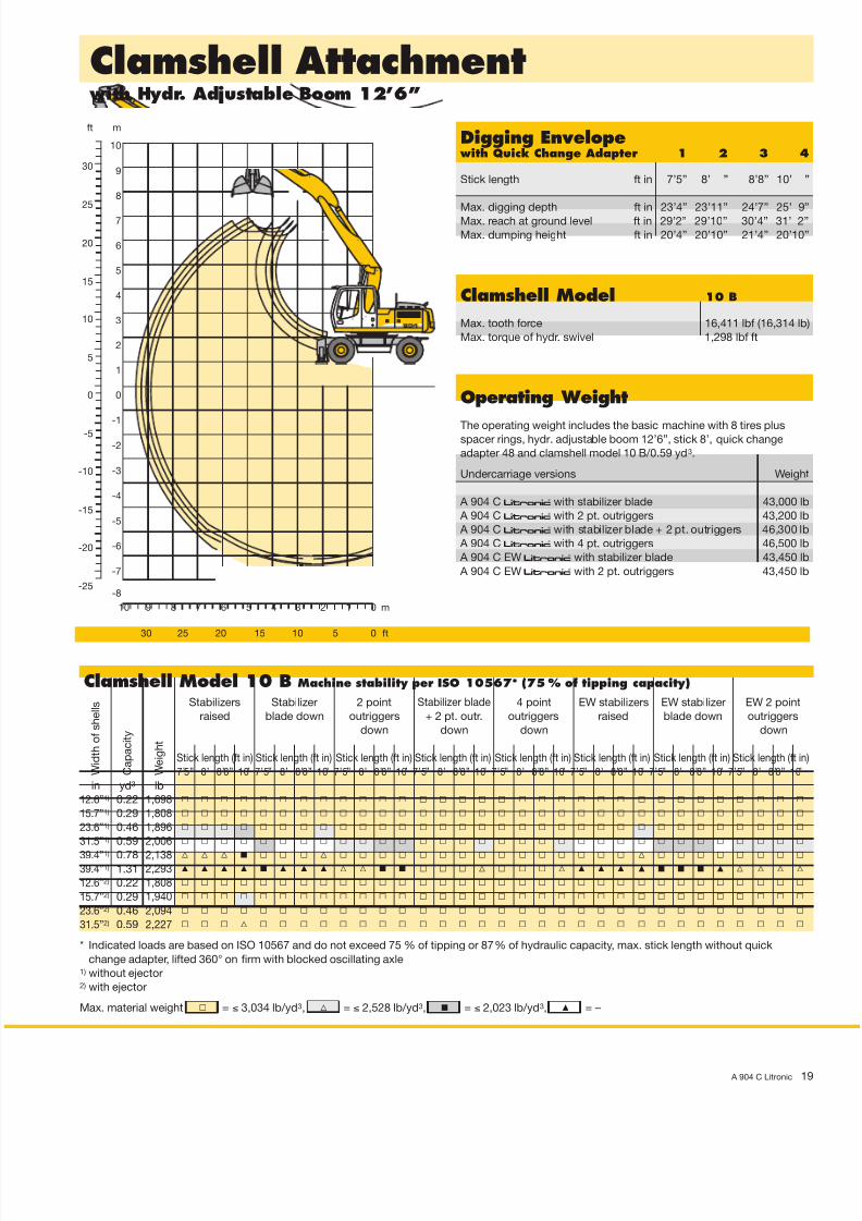
Clamshell Attachment with Hydr. Adjustable Boom 12’6”
A 904 C Litronic 1
Digging Envelope with Quick Change Adapter 1 2 3 4
Stick length ft in 7’5” 8’ ” 8’8” 10’
Max. digging depth ft in 23’4” 23’11” 24’7” 25’ 9
Max. reach at ground level ft in 29’2” 29’10” 30’4” 31’ 2
Max. dumping height ft in 20’4” 20’10” 21’4” 20’10
Operating Weight
The operating weight includes the basic machine with 8 tires plus spacer rings, hydr. adjustable boom 12’6”, stick 8’, quick change
adapter 48 and clamshell model 10 B/0.59 yd3.
Undercarriage versions Weigh
A 904 C litronic̀ with stabilizer blade 43,000 lb
A 904 C litronic̀ with 2 pt. outriggers 43,200 lb
A 904 C litronic̀ with stabilizer blade + 2 pt. outriggers 46,300 lb
A 904 C litronic̀ with 4 pt. outriggers 46,500 lb
A 904 C EW litronic̀ with stabilizer blade 43,450 lb
A 904 C EW litronic̀ with 2 pt. outriggers 43,450 lb
Clamshell Model 10 B
Max. tooth force 16,411 lbf (16,314 lb
Max. torque of hydr. swivel 1,298 lbf ft
W i d t h o f s h e l l s
C a p a c i t y
W e i g h t
Clamshell Model 10 B Machine stability per ISO 10567* (75 % of tipping capacity)
Stabilizers Stabilizer 2 point Stabilizer blade 4 point EW stabilizers EW stabilizer EW 2 point
raised blade down outriggers + 2 pt. outr. outriggers raised blade down outriggers
down down down down
Stick length (ft in) Stick length (ft in) Stick length (ft in) Stick length (ft in) Stick length (ft in) Stick length (ft in) Stick length (ft in) Stick length (ft in
7’5” 8’ 8’8” 10’ 7’5” 8’ 8’8” 10’ 7’5” 8’ 8’8” 10’ 7’5” 8’ 8’8” 10’ 7’5” 8’ 8’8” 10’ 7’5” 8’ 8’8” 10’ 7’5” 8’ 8’8” 10’ 7’5” 8’ 8’8” 10
in yd3 lb
12.6”1) 0.22 1,698 Y Y Y Y Y Y Y Y Y Y Y Y Y Y Y Y Y Y Y Y Y Y Y Y Y Y Y Y Y Y Y Y
15.7”1) 0.29 1,808 Y Y Y Y Y Y Y Y Y Y Y Y Y Y Y Y Y Y Y Y Y Y Y Y Y Y Y Y Y Y Y Y
23.6”1) 0.46 1,896 Y Y Y Y Y Y Y Y Y Y Y Y Y Y Y Y Y Y Y Y Y Y Y Y Y Y Y Y Y Y Y Y
31.5”1) 0.59 2,006 Y Y Y Y Y Y Y Y Y Y Y Y Y Y Y Y Y Y Y Y Y Y Y Y Y Y Y Y Y Y Y Y
39.4”1) 0.78 2,138 V V V y Y Y Y V Y Y Y Y Y Y Y Y Y Y Y Y Y Y Y V Y Y Y Y Y Y Y Y
39.4”1) 1.31 2,293 v v v v y v v v V V y y Y Y Y V Y Y Y V v v v v y y y v V V V V
12.6”2) 0.22 1,808 Y Y Y Y Y Y Y Y Y Y Y Y Y Y Y Y Y Y Y Y Y Y Y Y Y Y Y Y Y Y Y Y
15.7”2) 0.29 1,940 Y Y Y Y Y Y Y Y Y Y Y Y Y Y Y Y Y Y Y Y Y Y Y Y Y Y Y Y Y Y Y Y
23.6”2) 0.46 2,094 Y Y Y Y Y Y Y Y Y Y Y Y Y Y Y Y Y Y Y Y Y Y Y Y Y Y Y Y Y Y Y Y
31.5”2) 0.59 2,227 Y Y Y V Y Y Y Y Y Y Y Y Y Y Y Y Y Y Y Y Y Y Y Y Y Y Y Y Y Y Y Y
* Indicated loads are based on ISO 10567 and do not exceed 75 % of tipping or 87 % of hydraulic capacity, max. stick length without quick
change adapter, lifted 360° on firm with blocked oscillating axle1) without ejector2) with ejector
Max. material weight = ≤ 3,034 lb/yd3, = ≤ 2,528 lb/yd3, = ≤ 2,023 lb/yd3, = –
8/10/2019 A904C-US-NTB02.08neu_7364-0
http://slidepdf.com/reader/full/a904c-us-ntb0208neu7364-0 20/24
vyVY
0 m123456789
0 ft51015202530
0
-1
-2
-3
-4
-5
0
-5
-10
-15
1
2
3
4
5
6
7
8
9
m
5
10
15
20
25
30
ft
-6-20
-7
10
-8-25
12
34
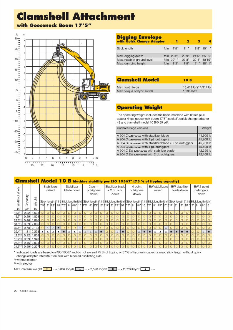
Clamshell Attachment with Gooseneck Boom 17’5”
20 A 904 C Litronic
Digging Envelope with Quick Change Adapter 1 2 3 4
Stick length ft in 7’5” 8’ ” 8’8” 10’ ”
Max. digging depth ft in 23’2” 23’9” 24’5” 25’ 9”
Max. reach at ground level ft in 29’ ” 29’8” 30’4” 30’10”
Max. dumping height ft in 18’3” 18’8” 19’ ” 18’ 1”
Operating Weight
The operating weight includes the basic machine with 8 tires plus spacer rings, gooseneck boom 17’5”, stick 8’, quick change adapter
48 and clamshell model 10 B/0.59 yd3.
Undercarriage versions Weight
A 904 C litronic̀ with stabilizer blade 41,900 lb
A 904 C litronic̀ with 2 pt. outriggers 41,900 lb
A 904 C litronic̀ with stabilizer blade + 2 pt. outriggers 45,200 lb
A 904 C litronic̀ with 4 pt. outriggers 45,400 lb
A 904 C EW litronic̀ with stabilizer blade 42,350 lb
A 904 C EW litronic̀ with 2 pt. outriggers 42,100 lb
Clamshell Model 10 B
Max. tooth force 16,411 lbf (16,314 lb)
Max. torque of hydr. swivel 1,298 lbf ft
W i d t h o f s h e l l s
C a p a c i t y
W e i g h t
Clamshell Model 10 B Machine stability per ISO 10567* (75 % of tipping capacity)
Stabilizers Stabilizer 2 point Stabilizer blade 4 point EW stabilizers EW stabilizer EW 2 point
raised blade down outriggers + 2 pt. outr. outriggers raised blade down outriggers
down down down down
Stick length (ft in) Stick length (ft in) Stick length (ft in) Stick length (ft in) Stick length (ft in) Stick length (ft in) Stick length (ft in) Stick length (ft in)
7’5” 8’ 8’8” 10’ 7’5” 8’ 8’8” 10’ 7’5” 8’ 8’8” 10’ 7’5” 8’ 8’8” 10’ 7’5” 8’ 8’8” 10’ 7’5” 8’ 8’8” 10’ 7’5” 8’ 8’8” 10’ 7’5” 8’ 8’8” 10’
in yd3 lb
12.6”1) 0.22 1,698 Y Y Y Y Y Y Y Y Y Y Y Y Y Y Y Y Y Y Y Y Y Y Y Y Y Y Y Y Y Y Y Y
15.7”1) 0.29 1,808 Y Y Y Y Y Y Y Y Y Y Y Y Y Y Y Y Y Y Y Y Y Y Y Y Y Y Y Y Y Y Y Y
23.6”1) 0.46 1,896 Y Y Y Y Y Y Y Y Y Y Y Y Y Y Y Y Y Y Y Y Y Y Y Y Y Y Y Y Y Y Y Y
31.5”1) 0.59 2,006 Y Y Y Y Y Y Y Y Y Y Y Y Y Y Y Y Y Y Y Y Y Y Y Y Y Y Y Y Y Y Y Y
39.4”1) 0.78 2,138 Y V V y Y Y Y V Y Y Y Y Y Y Y Y Y Y Y Y Y Y Y V Y Y Y Y Y Y Y Y
39.4”1) 1.31 2,293 v v v v y v v v V V V y Y Y V y Y Y V y y v v v y y y y Y Y V y
12.6”2) 0.22 1,808 Y Y Y Y Y Y Y Y Y Y Y Y Y Y Y Y Y Y Y Y Y Y Y Y Y Y Y Y Y Y Y Y
15.7”2) 0.29 1,940 Y Y Y Y Y Y Y Y Y Y Y Y Y Y Y Y Y Y Y Y Y Y Y Y Y Y Y Y Y Y Y Y
23.6”2) 0.46 2,094 Y Y Y Y Y Y Y Y Y Y Y Y Y Y Y Y Y Y Y Y Y Y Y Y Y Y Y Y Y Y Y Y
31.5”2) 0.59 2,227 Y Y Y Y Y Y Y Y Y Y Y Y Y Y Y Y Y Y Y Y Y Y Y Y Y Y Y Y Y Y Y Y
* Indicated loads are based on ISO 10567 and do not exceed 75 % of tipping or 87 % of hydraulic capacity, max. stick length without quick
change adapter, lifted 360° on firm with blocked oscillating axle1) without ejector2) with ejector
Max. material weight = ≤ 3,034 lb/yd3, = ≤ 2,528 lb/yd3, = ≤ 2,023 lb/yd3, = –

8/10/2019 A904C-US-NTB02.08neu_7364-0
http://slidepdf.com/reader/full/a904c-us-ntb0208neu7364-0 21/24
v
y
V
Y
Ditchcleaning Attachment with Hydr. Adjustable Boom 12’6”
A 904 C Litronic 2
0 m123456789
0 ft51015202530
0
-1
-2
-3
-4
-5
0
-5
-10
-15
1
2
3
4
5
6
7
8
9
m
5
10
15
20
25
30
ft
-6-20
-7
10
10
123
4
Digging Envelope with Quick Change Adapter 1 2 3 4
Stick length ft in 7’5” 8’ ” 8’ 8” 10’
Max. digging depth ft in 17’9” 18’ 4” 19’ ” 20’
Max. reach at ground level ft in 28’3” 28’10” 29’ 6” 30’2
Max. dumping height ft in 24’1” 24’ 7” 24’11” 24’9
Max. teeth height ft in 31’ ” 31’ 6” 31’12” 31’6
Operating Weight
The operating weight includes the basic machine with 8 tires plus
spacer rings, hydr. adjustable boom 12’6”, stick 8’, quick change
adapter 48 and ditchcleaning bucket 78.7”/0.92 yd3.
Undercarriage versions Weigh
A 904 C litronic̀ with stabilizer blade 42,800 lb
A 904 C litronic̀ with 2 pt. outriggers 43,000 lb A 904 C litronic̀ with stabilizer blade + 2 pt. outriggers 46,100 lb
A 904 C litronic̀ with 4 pt. outriggers 46,300 lb
A 904 C EW litronic̀ with stabilizer blade 43,200 lb
A 904 C EW litronic̀ with 2 pt. outriggers 43,200 lb
C u t t i n g w i d t h
C a p a c i t y
I S O 7 4 5 1 1 )
W e i g h t
Ditchcleaning Buckets Machine stability per ISO 10567* (75 % of tipping capacity)
Stabilizers Stabilizer 2 point Stabilizer blade 4 point EW stabilizers EW stabilizer EW 2 point
raised blade down outriggers + 2 pt. outr. outriggers raised blade down outriggers
down down down down
Stick length (ft in) Stick length (ft in) Stick length (ft in) Stick length (ft in) Stick length (ft in) Stick length (ft in) Stick length (ft in) Stick length (ft in
7’5” 8’ 8’8” 10’ 7’5” 8’ 8’8” 10’ 7’5” 8’ 8’8” 10’ 7’5” 8’ 8’8” 10’ 7’5” 8’ 8’8” 10’ 7’5” 8’ 8’8” 10’ 7’5” 8’ 8’8” 10’ 7’5” 8’ 8’8” 10
in yd3 lb
59.1” 0.65 0,882 Y Y Y Y Y Y Y Y Y Y Y Y Y Y Y Y Y Y Y Y Y Y Y Y Y Y Y Y Y Y Y Y
78.7” 0.92 1,102 Y Y Y V Y Y Y Y Y Y Y Y Y Y Y Y Y Y Y Y Y Y Y Y Y Y Y Y Y Y Y Y
94.5” 1.11 1,301 V V y y Y V V y Y Y Y Y Y Y Y Y Y Y Y Y Y V V y Y Y Y V Y Y Y Y
63.0”2) 1.05 1,698 V y y v V V V y Y Y Y Y Y Y Y Y Y Y Y Y V V V y Y Y Y V Y Y Y Y
63.0”2) 1.31 1,764 y v v v y y y v Y V V y Y Y Y V Y Y Y V y y y v V V y y Y Y V V
78.7”2) 0.92 1,786 V V y y Y Y V V Y Y Y Y Y Y Y Y Y Y Y Y Y Y V V Y Y Y Y Y Y Y Y
78.7”2) 1.31 1,918 v v v v y y v v V V V y Y Y Y V Y Y Y V y y v v V y y y Y V V V
* Indicated loads are based on ISO 10567 and do not exceed 75 % of tipping or 87 % of hydraulic capacity, max. stick length without quick
change adapter, lifted 360° on firm with blocked oscillating axle1) comparable with SAE (heaped)2) with 2 x 50° rotator
= ≤ 3,034 lb/yd3 max. material weight
= ≤ 2,528 lb/yd3 max. material weight
= ≤ 2,023 lb/yd3 max. material weight
= –

8/10/2019 A904C-US-NTB02.08neu_7364-0
http://slidepdf.com/reader/full/a904c-us-ntb0208neu7364-0 22/24
v
y
V
Y
Ditchcleaning Attachment with Gooseneck Boom 17’5”
22 A 904 C Litronic
0 m123456789
0 ft51015202530
0
-1
-2
-3
-4
-5
0
-5
-10
-15
1
2
3
4
5
6
7
8
9
m
5
10
15
20
25
30
ft
10
-6-20
-710
12 3
4
Digging Envelope with Quick Change Adapter 1 2 3 4
Stick length ft in 7’ 5” 8’ ” 8’ 8” 10’ ”
Max. digging depth ft in 17’ 5” 18’ 1” 18’ 8” 20’ ”
Max. reach at ground level ft in 28’ 3” 28’10” 29’ 4” 30’ ”
Max. dumping height ft in 21’12” 22’ 6” 22’10” 21’12”
Max. teeth height ft in 28’10” 29’ 4” 29’ 8” 28’ 7”
Operating Weight
The operating weight includes the basic machine with 8 tires plus
spacer rings, gooseneck boom 17’5”, stick 8’, quick change adapter
48 and ditchcleaning bucket 78.7”/0.92 yd3.
Undercarriage versions Weight
A 904 C litronic̀ with stabilizer blade 41,700 lb
A 904 C litronic̀ with 2 pt. outriggers 41,700 lb A 904 C litronic̀ with stabilizer blade + 2 pt. outriggers 45,000 lb
A 904 C litronic̀ with 4 pt. outriggers 45,200 lb
A 904 C EW litronic̀ with stabilizer blade 42,100 lb
A 904 C EW litronic̀ with 2 pt. outriggers 41,900 lb
C u t t i n g w i d t h
C a p a c i t y
I S O 7 4 5 1 1 )
W e i g h t
Ditchcleaning Buckets Machine stability per ISO 10567* (75 % of tipping capacity)
Stabilizers Stabilizer 2 point Stabilizer blade 4 point EW stabilizers EW stabilizer EW 2 point
raised blade down outriggers + 2 pt. outr. outriggers raised blade down outriggers
down down down down
Stick length (ft in) Stick length (ft in) Stick length (ft in) Stick length (ft in) Stick length (ft in) Stick length (ft in) Stick length (ft in) Stick length (ft in)
7’5” 8’ 8’8” 10’ 7’5” 8’ 8’8” 10’ 7’5” 8’ 8’8” 10’ 7’5” 8’ 8’8” 10’ 7’5” 8’ 8’8” 10’ 7’5” 8’ 8’8” 10’ 7’5” 8’ 8’8” 10’ 7’5” 8’ 8’8” 10’
in yd3 lb
59.1” 0.65 0,882 Y Y Y Y Y Y Y Y Y Y Y Y Y Y Y Y Y Y Y Y Y Y Y Y Y Y Y Y Y Y Y Y
78.7” 0.92 1,102 Y Y Y V Y Y Y Y Y Y Y Y Y Y Y Y Y Y Y Y Y Y Y Y Y Y Y Y Y Y Y Y
94.5” 1.11 1,301 V V y y Y V V V Y Y Y Y Y Y Y Y Y Y Y Y Y V V V Y Y Y Y Y Y Y Y
63.0”2) 1.05 1,698 V V y y Y V V y Y Y Y Y Y Y Y Y Y Y Y Y Y V V y Y Y Y Y Y Y Y Y
63.0”2) 1.31 1,764 y v v v y y y v Y V Y y Y Y Y y Y Y Y y y y y v V V y y Y Y Y y
78.7”2) 0.92 1,786 V V V y Y Y Y V Y Y Y Y Y Y Y Y Y Y Y Y Y Y V V Y Y Y Y Y Y Y Y
78.7”2) 1.31 1,918 y v v v y y y v Y V V y Y Y V y Y Y V y y y y v V V y y Y Y V y
* Indicated loads are based on ISO 10567 and do not exceed 75 % of tipping or 87 % of hydraulic capacity, max. stick length without quick
change adapter, lifted 360° on firm with blocked oscillating axle1) comparable with SAE (heaped)2) with 2 x 50° rotator
= ≤ 3,034 lb/yd3 max. material weight
= ≤ 2,528 lb/yd3 max. material weight
= ≤ 2,023 lb/yd3 max. material weight
= –

8/10/2019 A904C-US-NTB02.08neu_7364-0
http://slidepdf.com/reader/full/a904c-us-ntb0208neu7364-0 23/24 A 904 C Litronic 2
S = Standard, O = Option
Options and/or special attachments, supplied by vendors other than Liebherr, are only to be installed with theknowledge and approval of Liebherr to retain warranty.
Equipment
Undercarriage S O
Two circuit travel brake with accumulator •
Travel motor protection •
Outrigger cylinder rod guards •
Creeper speed electrically switchable from cab •
New tires •
Service free parking brake •
Independent outrigger control •
Choice of tires •
Auto check valve directly on each stabilizer cylinder •
Proportional power steering with mechanical back up •
Customized colors •
Two lockable storage boxes •
Lockable storage box additional
Two-speed power shift transmission •
Operator’s Cab S O
Storage tray •
Displays for engine operating condition •
Mechanical hour meters, readable from outside the cab •
Roof hatch •
Adjustable roof vent
6-way adjustable seat •
Air pressure operator seat with heating and head-rest •
Seat and consoles independently adjustable •
Extinguisher •
Removable customized foot mat •
Dome light •
Cab heater with defroster •
Coat hook •
Air conditioning •
Cooler •
Adjustable steering wheel •
Bullet proof window (fixed installation – can not be opened) •
Radio stereo •
Radio installation •
Rain hood over front window opening •
Beacon •
Tinted windows •
Door with sliding window •
Optical and acoustical warning if outriggers are not fully retracted •
Auxiliary heating •
Sun shade •
Sun blinds •
Electronic theft protection •
Wiper blades •
Cigarette lighter and ashtray •
Additional flood lights •
Uppercarriage S O
Electric fuel tank filler pump •
Maintenance-free swing brake lock •
Handrails, Non slip surfaces •
Main switch for electric circuit •
Engine hood with lift assistance •
Pedal controlled positioning swing brake •
Reverse travel warning system •
Sound insulation •
Customized colors •
Pin lock upper/lower •
Maintenance-free HD-batteries •
Extended tool kit •
Lockable tool box •
Tool kit •
Hydraulics S O
Hydraulic tank shut-off valve •
Extra hydr. control for hydr. swivel •
Pressure compensation •
Hook up for pressure checks •
Pressure storage for controlled lowering of attachments with engine
turned off •
Filter with partial micro filtration (5 µm) •
Electronic pump regulation •
Step less mode system (ECO) •
Flow compensation •
Four mixed modes, can also be adjusted •
Full flow micro filtration •
Bio degradable hydraulic oil •
Pressure compensation
Flow summation
Tool Control •
Additional hydraulic circuits •
Attachment S O
Flood lights on boom •
Hydr. lines for clam operation •
Sealed pivots •
Safety lift hook on hoe buckets •
Liebherr line of clams •
Liebherr semi-automatic central lubrication system •
Liebherr fully-automatic central lubrication system •
Likufix •
Safety check valves on hoist cylinder •
Safety check valves on stick cylinder •
Hose quick connection •
Hydraulic or manual quick change tool adapter •
Customized colors •
Special buckets and other tools •
Overload warning device •
Two way valves for bucket/clam use •
Locking of connections for clam operation •
Cylinders with shock absorber •
Engine S OTurbo charger •
Unit pump system •
Cold start aid •
Sensor controlled engine idling •
Air filter with pre-cleaner main- and safety element •
All illustrations and data may differ from standard equipment. Subject to change without notice.

8/10/2019 A904C-US-NTB02.08neu_7364-0
http://slidepdf.com/reader/full/a904c-us-ntb0208neu7364-0 24/24
Li bh C i E i C
Printed in Germany by Geiselmann RG-BK-RP LHB/VF 10472024-1.5-02.08
The Liebherr Group of Companies
Wide product rangeThe Liebherr Group is one of the largest construction
equipment manufacturers in the world. Liebherr’s high-
value products and services enjoy a high reputation in
many other fields, too. The wide range includes domes-
tic appliances, aerospace and transportation systems,
machine tools and maritime cranes.
Exceptional customer benefitEvery product line provides a complete range of models
in many different versions. With both its technical excel-
lence and acknowledged quality, Liebherr products offer
a maximum of customer benefits in practical application.
State-of-the-art technology To provide consistent, top quality products, Liebherr
attaches great importance to each product area, its
components and core technologies. Important modules
and components are developed and manufactured in-
house, for instance the entire drive and control techno-
logy for construction equipment.
Worldwide and independentHans Liebherr founded the Liebherr family company in
1949. Since that time, the enterprise has steadily grown to
a Group of 100 companies with over 30,000 employees
located on all continents. The corporate headquarters of
the Group is Liebherr-International AG in Bulle, Switzerland.
The Liebherr family is the sole owner of the company.
www.liebherr.us