alteon l4 switch basic training
TRANSCRIPT

Alteon Application Switch Basics

Overview of Alteon

Alteon - 3/
What is L4 Switch? – L2 Switch
Switching 의 결정 요소가 Mac 주소가 된다 (Switch 의 FDB 테이블 참조 ).
D-mac
S-mac
D-ip
S-ip
B620
D-Port
C-Port
B620
Layer 2
Layer 3
Layer 4
Ping 10.1.1.1
10.1.1.1 의 Mac 주소는
어느 포트에 ?
IP : 10.1.1.1Mac : 00-00-E2-6D-7A-F8

Alteon - 4/
What is L4 Switch? – L4 Switch Switching 의 결정 요소가 Service Type(Port) 이 된다 .
D-mac
S-mac
D-ip
S-ip
B620
D-Port
C-Port
B620
Layer 2
Layer 3
Layer 4
http://www.ringnet.co.kr
VIP 로 오는 http Service인 경우 리얼서버 3 개중 하나로 Switching 한다 .
VIP 10.1.1.100
10.1.1.1 10.1.1.2 10.1.1.3
DNS

Alteon - 5/
Alteon Web Switch Platforms
Feature/Function
Industry LeadingWeb Switching (L4-7)
AD3• Eight 10/100 BASE-T ports• One 1000BASE-SX uplink• 2 MB of memory per port• 336K concurrent sessions• 8 Gbps backplane capacity
180e• Eight 10/100/1000 Mbps ports• One 1000BASE-SX port• 2MB of memory per port• 336K concurrent sessions• 8 Gbps backplane capacity
184• Nine 10/100/1000 Mbps ports• 4 MB of memory per port (1-8)• 8 MB of memory on port 9• 512K concurrent sessions• 8 Gbps backplane capacity
AD4• Eight 10/100 BASE-T ports• One 1000BASE-SX uplink• 4 MB of memory per port (1-8)• 8 MB of memory on port 9 • 512K concurrent sessions• 8 Gbps backplane capacity
WSM• 4- 10/100 TX or Gig SX ports • 80MB of Memory• 512K concurrent sessions
AD4
AD3
180e
184
WSM
Pri
ce

Alteon - 6/
Alteon Web Switches
Selectable 8 x 10/100 or 1000SX Ethernet ports
1- 100 or Gigabit Ethernet uplink on Port 9
6 LEDs/port- Data- Link- Active
Console port
AC and DC power
available
“We went with Alteon’s AD4 because of it’s industry leading performance and Layer 7 logic.”
Alteon 184
“Alteon 184 outclassed all of its competitors under the heaviest load conditions and demonstrated superior performance!”
Alteon - 7/
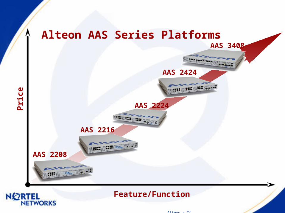
Alteon AAS Series Platforms
Feature/Function
Pri
ce
AAS 2208
AAS 2424
AAS 2216
AAS 3408
AAS 2224

Alteon - 8/
AAS Series Model Number
Alteon Application Switch xyzz
First Digit = x Identifies series2000 = Fast Ethernet; 3000 = Gigabit Ethernet
Second Digit = y Indicates the number of optical Gigabit ports(“uplink” – but can be used for anything)
Last Two Digits = zz Indicates the number of ports for servers/devices
Example: Alteon Application Switch 2224Fast Ethernet; 2 optical GE ports; 24 FE ports

Alteon - 9/
Alteon Application Switch 2224
Nortel Networks
1
2
3
4
5
6
7
8
9
10
11
12
13
14
15
16
17
18
19
20
21
22
23
24
25 26
Note: GBIC is required for GE.
DB9Console
RJ45Management
Port

Alteon - 10/
Alteon Application Switch 2424
RJ45 Auto 10/100Fast Ethernet Ports
LEDs on Port
SFP GBICs: 1000Base-SXOr 1000Base-LX with LC Connectors
LEDs: SFPLED: Power
LED: Fan
DB9Console
RJ45Management
Port
12 7
8 910 15
16 1718 23
24 25 261-RUform factor
{27 28

Alteon - 11/
Alteon Application Switch 3408
RJ45 Auto 10/100/1000
Ethernet Ports
SFP GBICs: 1000Base-SXOr 1000Base-LX with LC Connectors
DB9Console
RJ45 ManagementPort
Optional Copper or Optical
1-RUform factor
{ 1 4 3 5 864 5 6 72 3
119 10 12
LEDs: SFP
LED: PowerLED: Fan

Alteon - 12/
Summary: Alteon Switch Positioning
AD4
AD3 180e
184
Fe
atu
re/F
un
cti
on
/Pe
rfo
rma
nce
Passport 8600 Layer 2-7 Routing Switch
Fast Ethernet Gig Ethernet Modular
Alteon Web Switches
A3408
AAS2424
AAS2208
AAS2216
AAS2224

장비별 지원 사항
분류 AD3 AD4 180E 184 WSMAAS
2208
AAS
2216
AAS
2224
AAS
2424
AAS
3408
Port 수8-10/100M,1-1000M
8-10/100M,
1-1000M
8-10/100M/1000M,
1-1000M
9-10/100M/
1000M4-1000M
8-10/100M,
2-1000M
16-10/100M,2-1000M
24-10/100M,
2-1000M
24-10/100M,
4-1000M
4-1G
(RJ-45),
4-1G
(SFP),
4-1G
(RJ-45/
SFP 선택형 )
Total Memory
18M 40M 18M 40M 80M 256M 384M 640M 640M 640M
Concurrent Session
336K 512K 336K 512K 512K 600K 1M 2M 2M 2M
Switch Capacity
8Gbps 8Gbps 8Gbps 8Gbps - 16Gbps 16Gbps 16Gbps 16Gbps 16Gbps

Alteon - 14/
CPU load 가 높은 경우 아래를 참고 해서 원인 판단 가능
MP (Management Processor)
• Configuration Manager • All switch management including SNMP, WebUI, Telnet, SSH, RADIUS, Syslogs, Traps, etc.., • STP (Spanning Tree Protocol) • Routing protocols such as RIP1, OSPF, BGP • VRRP • Real server health checking • Statistics collection from SPs
SP (Switch Processor)
• Processes received packets from the port • Transmits packets out to the port• L2 bridging • VLAN and Trunk management• VLAN tag insertion by HW• L3 forwarding • L4-7 packet processing • Session table management • BWM classification• BWM (shaping & policing) • Statistics reporting to MP
Alteon L4 Switch Basic

Alteon - 16/
• The switch is a Layer 2 device with Layer 3 functionality
• All Layer 4 to 7 features are off by default• Allows for 16 instance of Spanning Tree Group• Supports 10/100/1000Mbps Ethernet• Supports Telnet, CLI, WebUI• Boots in 10 seconds!!
Switch Basics

Alteon - 17/
Console Connection
• Requires standard DB9 cable with male connection• Standard connection
– 9600 baud– 8 data bits– No parity bit– 1 stop bit– No flow control
• Hyper-terminal or any other terminal emulator

Alteon - 18/
Upgrading Switch Code
• Two software images plus boot image• Upgrading procedure
– Option 1 - Download image from TFTP server to switch– Option 2 – Load image via serial download
• /boot menu– gtimg – downloads new image via TFTP
• Where to put image <image 1/image 2/boot>• TFTP server IP address• Image file name
– _mp vs. _boot vs._bin– .180e vs. .184
– ptimg – transfers image to a TFTP server• Reset switch with /boot/reset command

Alteon - 19/
Setting the Switch Configuration Block
• Two user configuration blocks or a factory configuration
• /boot/conf command– active – backup– factory

Alteon - 20/
Setting Telnet
• Telnet capabilities• Enable/disable telnet
– /cfg/sys/tnet <ena|dis>– From console port only– Telnet timeout default set to 5 minutes
Alteon - 21/
Switch Timeout
• Switch CLI session timeout– 1 to 60 minutes– Default set to 5 minutes
• /cfg/sys/idle <idle time>– Set time from 1 to 60 minutes

Alteon - 22/
Setting Switch Date and Time
• /cfg/sys/date <date>– System# date– Enter year [2004]: 2004– Enter month [4]: 4– Enter day [18]: 18– System clock set to 14:11:46 Sun Apr 18, 2004.
• /cfg/sys/time <24 hour time>– System# time– Enter hour in 24-hour format [14]: 14– Enter minutes [11]: 12– Enter seconds [50]: 00– System clock set to 14:12:00 Sun Apr 18, 2004.

Alteon - 23/
Setting the Switch Banner
• Login banner up to 80 characters • Banner enabled for console/telnet user/admin logins• /cfg/sys/bannr <banner>

Alteon - 24/
Setting the Switch Management Network
• Allows the administrator to set a workstation or range of workstations that are allowed to have management access to the switch
• /cfg/sys/mnet <IP Address>• /cfg/sys/mmask <Subnet Mask>• Limits internal stack access

Alteon - 25/
Port Configurations• Configure individual physical switch ports
– /cfg/port <port number> fast menu• Link speed - speed <any/10/100>• Duplex mode - mode <any/full/half>• Flow control - fctl <auto/rx/tx/both/none>• Auto-negotiation enable/disable - auto <e|d>
• Enable/disable a switch port– /cfg/port <port number> menu
• ena/dis (or shorter term e/d)

Alteon - 26/
IP Interfaces
• Switch supports 256 IP Interfaces• Switch supports 246 Vlans
– range 1~4094
• The interfaces are logical and are associated with Vlans• Vlans are in turn associated with Physical ports• Each port can support 246 Vlans by using Vlan Tagging• All IP interfaces can be on different subnets all in the same
Vlan• Interfaces need to be enabled in order to become active

Alteon - 27/
IP Interfaces
Switch Operation AD3/4 and 180e/184
VLAN's 246
IP I/F's 256
Routing ProtocolsRIP I, OSPF, BGP Lite (up to 4 peers)
Routes 1K
Static Routes 128
ARP Cache 4096
STP Domains 16(webos 10.0), 1(webos 9.0)
MAC Addresses 2K

Alteon - 28/
Changing Password
• Default Password is admin• To change a user level password
– Administrator access to switch with admin password– /cfg/sys/user menu then select user to change
• usrpw - Set user password (user)• sopw - Set SLB operator password (slboper)• l4opw - Set L4 operator password (l4oper)• opw - Set operator password (oper)• sapw - Set Slb administrator password (slbadmin)• l4apw - Set L4 administrator password (l4admin)• admpw - Set administrator password (admin)

Alteon - 29/
Switch Administration Security Protection• user
– Generic switch access to view switch statistics and status information
– Default - user• slboper
– Operator that manages web servers and other Internet services and their loads
• l4oper
– Operator that manages traffic on the lines leading to the Internet services• oper
– Operator that manages all functions of the switch and is permitted to reset ports or the entire switch

Alteon - 30/
• slbadmin
– Administrator that configures and manages web servers and other Internet services and their loads
• l4admin
– Administrator that configures and manages the traffic on the lines leading to the shares Internet services
– Default - l4admin• admin
– The Superuser Administrator that has access to all of the switch's management and configuration features
– Default - admin
• Password determines user level
Switch Administration Security Protection

Alteon - 31/
Setting Up a Syslog
• Configure up to two hosts to capture syslog messages
• /cfg/sys/syslog/host <ip address>• Eight different types of syslog messages
– EMERG: system is unusable– ALERT: immediate action required– CRIT: critical condition– ERR: error condition/operation– WARNING: warning condition– NOTICE: normal but significant condition– INFO: information message– DEBUG: debug level message

Alteon - 32/
Setting Up SNMP
• Allows for the switch to support SNMP network management
– /cfg/snmp menu• System name, system location, contact information (64 characters each)• Read/write community strings (32 characters)• IP address of up to 2 hosts to receive system traps (allows for community
string access)
Alteon - 33/
Upgrading Switch Software Key
• SLB and WCR software come with the switch• GSLB and BWM are optional• If you want to run GSLB or BWM
– Call Alteon to obtain license certificate (key)• License is MAC Address specific
– /oper/swkey• Enter swkey

Alteon - 34/
– /Move back to Main menu
– ..Move back one menu level
– .Show menu for current context
– applyMakes changes active in volatile RAM
– saveSave changes to non-volatile Active Flash bank.
– diff [flash]View un-applied [applied but un-saved] changes
– revert [apply]Revert un-applied [applied but not saved] changes
Command Line Basics

Alteon - 35/
• /info/linkView physical port Link state
• /info/vrrpShow VRRP information
• /info/ipShow IP Interface Information
• /info/route/dumpDump the routing table
• /info/slb/dumpShow SLB state and information
• /info/slb/sess/dumpDump session table or find entry by clients IP address
• /stat/slb/<virt x> <real x> <group x>View SLB statistics for Virtual Server, Real Server or Group
Useful Reference Material

Alteon - 36/
Useful Reference Material
• Glossary– Service
Part of a Virtual Server which associates a TCP or UDP port and Group to be load balanced
– Virtual Server Comprises of a VIP and and up to 8 services.
Up to 256 Virtual Servers per switch
– VIP (Virtual IP Address) Destination IP to load balance service requests from clients
– Real [server] A physical server - May have more than 1 RIP bound to it
– RIP (Real IP Address) IP address on a Real server - Up to 256 (4096) RIP per switch

Architecture issue

Alteon - 38/
Switch Overview• Each switch supports the following:
– 10/100/1000 Ethernet– VLAN Tagging - 802.1.Q– Trunking – up to 4 GE or 6 FE ports– SNMP– Routing (RIP, OSPF, BGP “Lite”)– Syslog– SSH– Telnet

Alteon - 39/
MAC Addresses• Each Tigon switch is assigned 16 MAC addresses by
manufacturing. The first three octets (OUI) are currently 00:60:cf
• These 16 MAC addresses are assigned as follows:– One to the MP and is used for routing and management– One is assigned to each SP and is used as the MAC address of the PIP– Two are used as Virtual MAC addresses– The remaining 4 are undefined

Alteon - 40/
WebOS Software
• Runs proprietary software coded in C++ and Assembler
• Majority of functions are programed into the ASICs • Image sizes are between 500KB and 1MB• Requires a Boot Image to boot switch – Boot Image
can be different version to OS• Solid state switch means boot process takes 10
seconds
Alteon - 41/
WebOS Software
• Configs and Image stored in non-volatile internal flash memory
• Three config banks (TFTP or Text up/download)– Factory Default– Active– Backup
• Two Image banks (TFTP or Serial upload)– Image 1– Image 2

Alteon - 42/
• WebOS file name format– Version_File Type.Product (e.g. 100309_mp.184) where:
FileType
‘mp’ for core WebOS code (TFTP upload) ↔ ‘AlteonOS’ (AAS)
‘boot’ for boot code (TFTP upload) ↔ ‘Boot’ (AAS)
‘bin’ for both above (Serial upload) ↔ ‘Serial’ (AAS)
Product
‘180E’ for 180E and AD3
‘184’ for 184 and AD4
‘img’ for AAS
WebOS Software

Alteon - 43/
...
8 Gbps Switch Backplane
Management Module
Switch Ports
Memory Flash
WebIC
Memory
Fwd Engine
RISC
RISCWebIC
Memory
Fwd Engine
RISC
RISCWebIC
Memory
Fwd Engine
RISC
RISC
RISC RISC
• Distributed architecture• WebIC: network processing ASIC with hardware-assisted forwarding
engine and dual RISC processors• Up to 20 RISC processor per switch• Separate centralized switch management processors
Switch Architecture

Alteon - 44/
CPU CPU CPU CPU CPU CPU CPU CPU
Unattached port
Client
Server
DA_X, SA_3, RIP_A
• Memory at all ports pooled and utilized at all times– Session entries kept in memory local to designated CPUs– Global session table kept for cookie persistent sessions– All ports store all filtering/redirection policies
DA_X, SA_1, RIP_A DA_Y, SA_2, RIP_B DA_X, SA_1, RIP_A
Performance of distributed architecture with centralized architecture’s resource utilization
SA_1DA_X
SA_3DA_X
SA_2DA_Y
SA_1DA_X
• CPUs at all ports actively share L4-7 processing load– Each ingress packet hashed to one of 8 ports for L4-7 processing– Hashing algorithm ensures even distribution of Internet traffic– Packets in same session always hashed to the same CPU
Server
Virtual Matrix Architecture (VMA)
Can be turned off if not required/c/slb/adv/matrix ena/dis
Only used for Layer 4 – 7 sessionsRequires Version 8.0 or above WebOS

Alteon - 45/
SP(Switch Processor)/MP(Management Processor)SP(Switch Processor)/MP(Management Processor)
Switch Model SP1 SP2 SP3 SP4 MP
Alteon 2208Ports 1-8, and 9
Port 10 N/A N/A 1 개 (128M)
Alteon 2216Ports 1-12, and 17
Ports 13-16, and 18
N/A N/A 1 개 (128M)
Alteon 2224Ports 1-12, and 25
Ports 13-24 Port 26 N/A 1 개 (128M)
Alteon 2424Port 1-12, and 25
Ports 13-24, and 27
Port 26 Port 28 1 개 (128M)
All the four SPs are used in Virtual Matrix Architecture(VMA)

Alteon - 46/
Alteon Terminology• VIP, VMAC, Vport
– virtual server :• IP address, MAC address, TCP/UDP port
• RIP, RMAC, Rport– real server :
• IP address, MAC address, TCP/UDP port• CIP, CMAC, Cport
– Client :• IP address, MAC address, TCP/UDP port
• PIP, PMAC, Pport– proxy :
• IP address, MAC address, TCP/UDP port• Session
– TCP connection, UDP session, IP flow

Alteon - 47/
WebOS Traffic Flow• At each Ingress Port if Layer 4 parameters are
configured traffic flow follows these 3 processes:• Server
– Translates RIP to VIP, RPort to VPort and RMAC to VMAC
• Filter– Fires Filters and performs associated action
• Client - Translates VIP to RIP, VPort to Rport and VMAC to RMAC
• PIP -> RTP -> Server -> Filter -> Client -> L3/L2

Others

Alteon - 49/
Routing Protocols
• RIPv1, 1K route table entries• BGP4 subset supported (on AD4 and Alteon 184)• Static routes (up to 128)• Multiple default gateways
– Up to 4 per switch– Each default gateway is health checked using ICMP Echo

Alteon - 50/
VLAN Terminology
• VLANs– Separation of broadcast domains
• On a single networking device or multiple networking devices• VLAN ID
– Identifier of a specific broadcast domain– Can be “named” any number 1-4095 (per IEEE 802.1Q standard)
• PVID– Port VLAN Identifier– Used to associate a physical switch port with a specific VLAN
• Tagged Ports– Field in Ethernet frame used to identify a VLAN– Required if multiple VLANs are running over an single port
• Trunk Ports– Ports that carry more than one VLAN

Alteon - 51/
VLAN Configurations
• When running VLANs, there are two areas you need to configure VLAN identifiers:
– on the IP interface configuration– on the switch port
• To configure VLANs on the IP interface– /cfg/ip/if <if number>– vlan <vlan number> (1-4094)
• To configure VLANs on the port– /cfg/port <port number> menu– pvid <vlan number (1-4094)>
• To configure a port for multiple VLANs– /cfg/port <port number>/tag e– pvid <vlan number (1-4094)>

Alteon - 52/
Port Trunking
• Port trunking is combining multiple physical ports together to act as one single “Super Bandwidth” port
– Aggregate bandwidth– Built in fault tolerance

Alteon - 53/
Alteon’s Port Trunking Capabilities
• Up to four trunk groups consisting of 2 to 6 ports each• Up to six 10/100 mbps ports per group• Up to four 1000 mbps ports per group• Nortel Multilink Trunking (MLT) compatible• Cisco Etherchannel compatible• SUN Quad Fast Ethernet Adapter compatible

Server Load Balancing

Alteon - 55/
• Improves server utilization by transparently distributing traffic across server groups
• Provides increased reliability of user services and applications in the event of server or network failure
• Increases Web server performance by offloading server CPUs while increasing throughput
Server Load Balancing-advantage

Alteon - 56/
• Provides scalability for deploying new services without interrupting existing services
• Improves security by allowing private addresses to be used
• Allows intelligent management of content by inspecting Layer 7 information
• Provides switch and/or site resilience • MaxCon Real server capacity by intelligently
limiting the maximum connections
Server Load Balancing-advantage

Alteon - 57/
Server Load Balancing• Two ways to implement SLB
– VIP Based Load Balancing– Redirection Filter Based Balancing
• Server Load Balancing generally uses VIP • WCR and FWLB (+ other application LB) generally use
Redirection Filters• L4 to L7 Load Balancing supported• Alteon can LB on any TCP / UDP port
– However, some applications write Real server IP address in data portion and we may not be able to Load Balance

Alteon - 58/
Server Load Balancing
• Internet Traffic comes into a Virtual IP address which is resolved via DNS
• The VIP (Virtual IP Address) is associated with a Group of Real Servers
• The Alteon load balances the requests to the Real Servers
• Request forwarding is determined using an algorithm to establish the load on each Real Server
• Health checks are used to determine Real Server responsiveness and availability Servers
Virtual Web Site
VIP

Alteon - 59/
Server Load Balancing
• Real Servers– Can have Public or Private IP Addresses– Must run a TCP/UDP service– Up to 1024 Real Servers can be configured (Version 10)– Must Belong to a Group but can be a member of multiple Groups– an have maximum connections and timeout values assigned
• Groups– Support of up to 256 Groups– A Group can support 1024 Real Servers– Requires a Health Check metric– Requires a Load Balancing Metric

Alteon - 60/
Server Load Balancing
• Virtual IP Address (VIP)– Also called Virtual Server– Up to 256 VIPs can be configured– Each VIP must have at least one service (TCP/UDP port such as HTTP,
HTTPS, FTP etc.) associated with it – Must have a Group associated with each service– Each VIP can support 8 Services
Alteon - 61/
Server Load Balancing• VIP, VMAC, Vport
– virtual server :• IP address, MAC address, TCP/UDP port
• RIP, RMAC, Rport– real server :
• IP address, MAC address, TCP/UDP port• CIP, CMAC, Cport
– Client :• IP address, MAC address, TCP/UDP port
• PIP, PMAC, Pport– proxy :
• IP address, MAC address, TCP/UDP port• Session
– TCP connection, UDP session, IP flow

Alteon - 62/
Server Load Balancing
• Client / Server processing– Changes DIP from VIP to Real server IP and vice-versa– Client processing also creates session binding entry based on client SIP and
Sport
Server192.168.1.1
VIP 100.10.10.1Client
200.20.20.1
SIP 200.20.20.1DIP 100.10.10.1DMAC = V-MAC
SIP 200.20.20.1DIP 192.168.1.1DMAC = R-MAC
Client processing
SIP 192.168.1.1DIP 200.20.20.1DMAC = DGW-MAC
SIP 100.10.10.1DIP 200.20.20.1DMAC = C-MAC
Server processing

Alteon - 63/
TCP
IP
MACDst MAC
Src MAC
IP Checksum
Src IP Address
Dst IP Address
TCP Checksum
Src Port
Dst Port
Vmac
Cmac
B62A
CIP
VIP
037A
2155
80
Client
Vmac
Cmac
B62A
CIP
VIP
037A
2155
80
Alteon Switch
Rmac
Cmac
48A0
CIP
RIP
C107
2155
80
Rmac
Cmac
48A0
CIP
RIP
C107
2155
80
Real Server
Server Load Balancing• Client processing

Alteon - 64/
TCP
IP
MACDst MAC
Src MAC
IP Checksum
Src IP Address
Dst IP Address
TCP Checksum
Src Port
Dst Port
Cmac
Vmac
644B
VIP
CIP
761A
80
2155
Client
Cmac
Vmac
644B
VIP
CIP
761A
80
2155
Alteon Switch
Cmac
Rmac
823F
RIP
CIP
0A15
80
2155
Cmac
Rmac
823F
RIP
CIP
0A15
80
2155
Real Server
Server Load Balancing• Server processing

Alteon - 65/
Load Balancing Metrics• Load Based or Persistent Based• Load Based:
– Round Robin / Weighted Round Robin– Least Connections / Weighted Least Connections– Response Time– Bandwidth
• Persistent Based– Hash– Minimum Misses– Cookie Phash– SSL ID

Alteon - 66/
Hash• Source IP address used to generate an index into a table
containing all servers in group• All requests from same user are sent to same server
– True as long as no servers enter or leave group– Useful in e-commerce applications and FWLB where state must be maintained across
multiple TCP sessions
• Table recomputed when a server leaves or enters group• Weighting has no effect• Maximum connections option supported• If Application Redirection is configured the DIP is used instead

Alteon - 67/
Health Checks
• Health checks are used to determine the availability of the servers/service
• Servers are marked down when health check fails and up when health check succeeds
• All health check parameters are configurable:– Interval between checks– Number of failed Retry Counts to declare a server down– Number of Restore Counts to declare a server up
• Health Checks can be turned off

Alteon - 68/
Health Checks• Health check types are:
– ICMP– TCP - 3 way handshake on configured Service port– Content - HTTP– Application specific – Radius, SSL, POP, DNS etc.– Scripted – send sequence, expected response
• Note:– If you put all Services on a Real server into one Group and one
service fails, all services in that Group will be marked down– It is therefore recommended that Services are put into different
Groups when adding more than 1 service per Real server

Alteon - 69/
Health Checks• Group configuration item• Health checks occur every 2 seconds by default• For ICMP and TCP, 4 Retries will be attempted by default
before declaring a service down• For ICMP only, there must be 8 successful pings by default
before declaring service up• All other types will be declared up after 1 successful Health
check• If more than 1 service is configured on a Real server for a
Virtual Server, the Health checks occur sequentially for each service

Alteon - 70/
Health Checks- TCP
• Layer 4 connection requests (TCP SYN requests) sent to each configured service on each server
• Interval between attempts is user configurable• When connection request succeeds (switch receives TCP SYN
ACK response), connection is quickly closed (switch sends TCP FIN request to server)

Alteon - 71/
Direct Access Mode
• Direct Access Mode (DAM) is needed when:– Flows from a RIP that use a load balanced service should not be
load balanced
– Providing direct access to real servers– When a single RIP supports multiple VIPs– When delayed bindings are used

Alteon - 72/
Server Load Balancing Configuration
Alteon - 73/
Server Load Balancing
• All configuration happens under the /cfg/slb/ menu• Steps:
– Turn on SLB
– Set up Real Servers
– Set up Real Server Groups
– Configure VIP with required services
– Ensure correct processing (client/servers) is on for ports

Alteon - 74/
Server Load Balancing
• Troubleshooting– Is SLB enabled– Are the Reals enabled– Is the Virt enabled– Are the Groups associated with the correct Service
• Use the /info, /stat menus to get SLB information
Alteon - 75/
Virtual Router Redundancy Protocol

Alteon - 76/
VRRP• Defined by RFC 2338 for Layer 3 resilience – Virtual default gateway
• Upon switch failure the backup switches will select a new master
• Fail over takes 3 seconds
• VRRP uses IP multicast to communicate on 224.0.0.18
• Use of a multicast MAC address

Alteon - 77/
VRRP and Alteon WebOS
• VRRP– Allows multiple routers/switches to be active at the same time
• Alteon extensions to VRRP– Supports Layer 4 redundancy with Virtual Server Routers (VSR)– Share Mode

Alteon - 78/
VRRP Terminology• VRRP Router
– A router running VRRP, e.g., an Alteon switch
• Virtual Router (per RFC 2338)– Virtual interface that represents a set of IP addresses
• Virtual Interface Router (Alteon terminology)– A Virtual Router supporting layer 3 interfaces
• Virtual Server Router (Alteon terminology)– A Virtual Router supporting layer 4 (VIP) interfaces
• Virtual Router ID (VRID)– Unique within a LAN– Used for building the Virtual Router MAC address

Alteon - 79/
VRRP Terminology
• Virtual Router Master– Answers ARP requests– VRRP router that forwards packets sent to the virtual router
• Virtual Router Backups– VRRP routers available to assume forwarding responsibility for a virtual router if the
master fails

Alteon - 80/
VRRP
• How does VRRP work ?– Uses IP Multicast 224.0.0.18 for advertisements
– Advertisements sent every second by Master
– If Backup does not hear advertisement for 3 seconds, declares itself as Master
– Master sends MAC address 00-00-5E-00-01-VRID in response to ARP for Redundant IP address
– This MAC address is used by all Virtual Routers in a VIR
– VRID must be unique on a LAN

Alteon - 81/
Virtual Router MAC Address
• First five octets are the standard MAC prefix for VRRP packets as defined in RFC 2338
• VRID becomes the final octet• “00-00-5E-00-01-02” for VRID = 2

Alteon - 82/
VRRP• When configuring VRRP it is important that both switches be
configured identically – only IP Address and Priorities should be different
• The Priority of the switch determines who is master for that VIR and VSR
• Priorities are between 1 – 254 (default 100)• Highest Priority wins – if set the same then the highest MAC
address becomes Master• Preemption forces switch back to original Master on recovery
– can be turned off

Alteon - 83/
VRRP Tracking• Track on L3 parameters or L4 parameters• Parameters you can track on:
– L3 parameters– Virtual routers in master mode on the switch (vrs)– Active IP interfaces on the switch (ifs)– Active ports on the same VLAN (ports)
– L4 parameters– Physical ports that have active Layer 4 processing (l4pts)– Healthy Real Servers behind the VIP (reals)– In HSRP networks, the number of layer 4 client-only ports that receive HSRP
advertisements (hsrp)
• Each tracked parameter has a user configurable weight associated with it

Alteon - 84/
Redundant Operation Modes
• Active-standby– All switches actively perform load balancing and/or routing functions, but for
different virtual services and/or interfaces
• Active-Active– All switches can actively forward traffic for the same virtual services and/or
interface
• Hot Standby– One master with one or more backups. Only master processes layer 4 traffic

Alteon - 85/
Hot-Standby Redundancy
Active for Service #1
Active for Service #2
Active for Service #3
Standby for Service #1
Standby for Service #2
Standby for Service #3
Internet
Active Standby
Master Backup

Alteon - 86/
Active-Standby Redundancy
Active for Service #1
Standby for Service #2
Active for Service #3
Standby for Service #1
Active for Service #2
Standby for Service #3
Internet
Active Active
Master Backup

Alteon - 87/
Active-Active Redundancy
Internet
Active Active
Active for Service #1
Active for Service #2
Active for Service #3
Active for Service #1
Active for Service #2
Active for Service #3
Master Backup

Configuration and Operations
Alteon - 89/
VRRP Summary
• Alteon switches provide L3 and L4 redundancy, as well as support for sharing interfaces (Active-Active feature)
• Reviewed VRRP operations and services• Reviewed VRRP configuration

Alteon - 90/
Filters

Alteon - 91/
• The use of filters enable the administrator to allow and deny traffic, provides application redirection and increase network security
• Rich feature set that can allow packets to be:– Allowed– Denied– Redirected– NATed– TOS Bit Coloring
• Is the second stage of WebOS traffic flow
– PIP > RTP > Server > Filter > Client > L2/L3
Filters
Alteon - 92/
• Filter Processing done in ASIC providing wire speed access lists
• Off load network devices to take advantage of their strengths• 2048 filters per switch on AD4/184
– 224 filters on other models
• Filter number determines order of precedence• Once filter fires, packet is passed out of switch• When allow filter is created there is no explicit deny
Filters

Alteon - 93/
Filters• Normal filters perform a logical AND on all filter parameters
– Filter fires if all filter conditions are met
• Each Filter can have logging enabled or disabled• Caching of Filter entries is recommended when using TCP for
quick filter access

Alteon - 94/
Application Redirection

Alteon - 95/
Application Redirection• Allows traffic to be steered
transparently to the device proxying or handling the session
• Requires redirection filters• SSL, WCR and FWLB are
typical applications
Apply Filter 10
/cfg/slb/filt 10
sip any
dip any
proto tcp
sport any
dport http
action redir
rport http
group 10
ena

Firewall Load Balance & VPN LB

Alteon - 97/
Firewall Load Balancing

Alteon - 98/
• Eliminates single points of failure in a network
• Allows multiple active firewalls to operate in parallel
• Increases Internet access for internal users
Firewall Load Balancing

Alteon - 99/
• Firewall Load Balancing and Server Load Balancing can be performed on the same switch
• Highly Scalable solution• Up to 256 Firewalls can be Load Balanced in an
Alteon Firewall Load Balancing Sandwich • Firewall vendor independent
Firewall Load Balancing

Alteon - 100/
• Most Common Designs:– Directly Connected Firewalls – Bucher Box– Two Switch – Two Vlans or STP– Four switch – Four Vlans or STP– Bridging Firewalls– FWLB with Multiple DMZ – FWLB with NAT– FWLB with SLB/URL SLB
• With STP off VRRP allows for a much quicker fail over and is the recommended configuration
• See the “Complete Firewall Load Balancing Guide” for most configurations
Firewall Load Balancing

Alteon - 101/
FwLB Traffic Flow

Alteon - 102/
• Dirty Side– Allow Filters for local address/subnets/VRRP Broadcasts– Redirection Filter for all others– Enable FWLB on Filter– Static Routes to internal networks and to Real servers– Default Route to external networks
• Clean Side– Allow Filters for local address/subnets/VRRP Broadcast (dip 224.0.0.0/24)
/(and management area)– Redirection Filter for all others – Enable FWLB on Filter– Static Routes to external networks and to Real servers– SLB Configuration
Firewall Load Balancing-Traffic Flow

Alteon - 103/
• Ingress to Site
– Traffic hits the ingress port – server, filter, client– Redirection Filter Fires – hash on SIP and DIP– Select designated Real server – this is merely the corresponding IP Interface of
Clean Switch– Route via configured Static Route – changing only the DMAC to that of the Firewall– Firewall receives packet with original DIP (VIP) and routes to Switch for SLB– Arrives on Clean Switch, Client Processing replaces VIP with RIP and sends to
selected Real server– Server processes request
Firewall Load Balancing-Traffic Flow

Alteon - 104/
• Egress from Site
– Server sends packet back to Client– Server processing changes the RIP back to the VIP– Redirection Filter Fires - hash on SIP and DIP – still the same just reversed– Select designated Real server – this is merely the corresponding IP Interface of
the Dirty Switch– Route via configured static route – changing only the DMAC to that of the original
Firewall– Firewall receives packet with DIP of Client and routes to Dirty switch which sends
to upstream router via default gateway or static route
Firewall Load Balancing-Traffic Flow

Alteon - 105/
Firewall Load Balancing- Four Switch – Four Vlans no STP
Net B
Net C
Net D
Net E
InternetNet A
SLB Servers
Net F
FW 1
FW 2
M
B
M
B
R.1
R.2
R.3
R.4
.1
.1 .1
.1
R.1
R.2
R.3
R.4
Group 1 – Metric:Hash, Health:ICMP
Real 1, Backup Real 2Real 3, Backup Real 4Static 1 – Net D via Net B.1Static 2 – Net E via Net C.1
Group 1 – Metric:Hash, Health:ICMP
Real 1, Backup Real 2Real 3, Backup Real 4
Static 1 – Net B via Net D.1Static 2 – Net C via Net E.1
VIR's VIR's

Alteon - 106/
Firewall Load Balancing
• Common Mistakes– Real servers incorrectly numbered– No Routes to Networks on switch or Firewall– Firewall Policy does not allow Health Checks
through– Filters not set for local nets – No Dummy Filter for HTTP Health Checks– Static Routes are not consistent with Clean and
Dirty Side Reals– Incorrect Vlans configured on switch

Alteon - 107/
Virtual Private Network Load Balancing

Alteon - 108/
• Eliminates single points of failure in a network
• Allows multiple active VPN Gateways to operate in parallel
• VPN LB, Firewall LB and SLB can be performed on the same switch
• Scalable solution
VPN Load Balancing

Alteon - 109/
• Load balance up to 256 VPN Gateways in an Alteon 'sandwich‘• Multiple VPN Gateway products supported:
– Contivity– Checkpoint VPN-1– Netscreen– Intel
• Alteons maintain session state through Firewalls by using Hash Metric on SIP / DIP
• Uses ICMP Health Checks
VPN Load Balancing

Alteon Troubleshooting
Alteon - 111/
Bootup Issues
– Switch will not boot• Check LED patterns• May need to do a serial download
– Switch will boot but generates errors• Kernel Magic Wrong• Bad CRC• Could not read Active/Backup Config blocks

Alteon - 112/
Switch Management Issues
• Cannot ping switch IP interface(s)• Cannot telnet to the switch IP interface(s)• Cannot bring up WebUI• Switch does not log messages to syslog host• Switch does not send SNMP traps

Alteon - 113/
Link Issues
– Check cable (could be wrong type or a bad cable)– Check link negotiation (especially for Gigabit connections)– Check for port configuration mismatches on either end of the connection
(speed/mode/fctl)– Check /info/link– Check LED status

Alteon - 114/
Panic/Crash/Hang Issues
• Forcing a panic– /maint/panic– Hitting <ctrl-shift-6> keys together
• Collecting core dumps – /maint/uudmp (make sure terminal logging is turned ON prior to initiating
this)• Hard reset
– /boot/reset hard

Alteon - 115/
Connectivity Problems
• Flaky port connections
– check port statistics and look for error counters, for example
• /stats/port <port-number>/ether
• /stats/port <port-number>/if/ifInErrors
– check link on either ends (refer to Link Issues)
– check STP states
– check LED patterns
– note changes after disconnecting/connecting cable and/or resetting the switch

Alteon - 116/
L4 Issues
• Clients cannot access the real server’s service port directly– security feature
• Periodic health check failures (L3)– check IP interfaces on both ends
• Periodic health check failures (L4)– check if service is up and running– might need network traces between Alteon & the real servers
• Periodic health check failures (Content)– verify that the requested http object is present on the real server(s)

Alteon - 117/
L4 Issues (contd.)
• Clients cannot contact the VIP– check port state(s) for client connections– make sure the VIP is enabled– VIP needs to be ‘well known’
• Cannot telnet to the Switch– make sure the concerned interface is enabled
• Clients cannot access the services through the VIP when the real server(s) are marked operational
– possible condition with L3 health checks, service could be down but server might be UP

Alteon - 118/
Layer 2 - Useful CLI Commands
• /info/sys• /info/link• /info/dump• /cfg/dump• /stats/port <num> <ether/if/link>• /stats/if <>

Alteon - 119/
Layer 4 - Useful CLI Commands
• /info/slb• /cfg/slb/cur• /cfg/dump• /stats/slb/group <real-server-group-number>• /stats/slb/real <real-server-number>• /stats/slb/virt <virtual-server-number>• /stats/slb/maint

Alteon - 120/
감사합니다 .