analysis of the loads acting on rotary kiln & hydraulic design34-2-2019)/05.pdf · analysis of...
TRANSCRIPT

Çukurova Üniversitesi Mühendislik Mimarlık Fakültesi Dergisi, 34(2), ss. 45-55, Haziran 2019 Çukurova University Journal of the Faculty of Engineering and Architecture, 34(2), pp. 45-55, June 2019
Analysis of the Loads Acting on Rotary Kiln & Hydraulic Design
Sadık ÜNAL*1, Abdul Kadir EKŞİ1
1Çukurova Üniversitesi, Mühendislik Mimarlık Fakültesi, Makine Mühendisliği Bölümü, Adana Abstract Rotary kilns are the equipment for which crystallization and mixing is carried out with the help of high temperature. In this study, evaluation of replacing the electric motor which was used for moving the pinion gear with a hydraulic motor were carried out. The force and torque value exerts on the gear that provides the rotation of the rotary kiln was calculated analytically. As a result of the calculation, it was concluded that the pinion gear is exposed to 21,208 kN and the torque value is 6097,3 N.mm. By these values, detailed calculations of the hydraulic motor, pump, electric motor, minimum pipe diameter and reservoir capacity which constitute the rest of the system were performed. According to the calculations made, the final system was created by selecting the components to be used in the system. Keywords: Hydraulic design, Rotary kiln, Load analysis
Döner Fırına Etki Eden Yüklerin Analizi ve Hidrolik Dizayn Öz Döner fırınlar, yüksek sıcaklık yardımıyla kristalizasyon ve karışım işlemlerinin yapıldığı ekipmanlardır. Bu çalışmada, döner fırını hareket ettiren elektrik motorunun hidrolik bir motor ile değiştirilmesi irdelenmiştir. Döner bir fırının çalışması esnasında fırının dönmesini sağlayan dişlinin maruz kaldığı kuvvet ve tork değeri analitik olarak hesaplanmıştır. Yapılan hesaplama sonucu pinyon dişlinin maruz kaldığı 21.208 kN ve tork değerinin 6097.3 N.mm olduğu sonucuna varılmıştır. Bu değerlere göre sistemin geri kalanını oluşturan hidrolik motorun, pompanın, elektrik motorun, minimum boru çaplarının ve rezervuar kapasitesinin detaylı hesaplamaları gerçekleştirilmiştir. Yapılan hesaplamalara göre sistemde kullanılması gereken bileşenler seçilerek nihai sistem oluşturulmuştur. Anahtar Kelimeler: Hidrolik dizayn, Döner fırın, Yük analizi
*Sorumlu yazar (Corresponding author): Sadık ÜNAL, [email protected]
Geliş tarihi: 16.01.2019 Kabul tarihi: 28.06.2019
Ç.Ü. Müh. Mim. Fak. Dergisi, 34(2), Haziran 2019 45

Analysis of The Loads Acting on Rotary Kiln & Hydraulic Design
1. INTRODUCTION The shape of rotary kiln is a cylindrical vessel. The material slights in the horizontal inclined surface. The rotary kiln rotates very slowly about its axis. The raw material before crystallization is fed into cylindrical vessel from the end. During the rotation, material moves down slowly under high temperature in the form of mixing. Hot gases pass through the rotary kiln to crystallize. The flow direction of hot gases can be same with material flow. It is called co-current flow. But generally, the flow direction of hot gases can be opposite with material flow. It is called counter-current flow. Hot gases can be generated lots of different ways. But generally, the generation of hot gases can be categorized two different ways; external generated hot gases and internal generated hot gases. The large flame is obtained and spread out from the pipe. This pipe is called fire-burner. Different types of fuels can be used such as coal, gas or oil. The main components of a rotary kiln are the refractory lining, support tyres and rollers, shell, main drive gear, auxiliary drive gear and internal heat exchangers. Raw enters from a side in the kiln; remove the other side by moving the product in a hot environment [1]. The rotary kiln working principle is geared system. Electrical motor feeds the gear box and gives first move. After that, gear system transfers the motion to the other gears until reaching the large pinion on the tube. So, rotation is obtained by using electrical power. The material and hot gas are fed. The material rotates with high level of heat and crystal form of material is obtained [2]. The spur gear has been used at rotary kiln. The teeth of spur gears are parallel to the axis. The power is transmitted between two parallel shafts. The advantages of spur gears are less cost, simple construction and easy manufacturing. In addition to this, spur gears have highest efficiency compared to other gear types. Spur gears are used at high speed and high load applications [3]. There is no system directly driven hydraulic system at rotary kiln. Generally, mechanical driven rotary kiln system is preferred. Because, hydraulic
requires expertise compared to other systems. High capacity forces can be obtained by using hydraulic systems. Various studies are available for the design of rotary kiln in literature. Almost all works are related to gear system. Working principles are similar to each other. But every work was done by putting something new in literature. Dmitrij Ramanenka has analyzed the effects on the rotary kiln [4]. He was modeled the rotary kiln with respect to these effects. Especially, it has been about drive unit. Because, the drive unit is most affected by the external influences of the rotary kiln. He has categorized the effects under three main titles. These are mechanical effects, thermal effects and chemical effects. There are many factors that can cause sudden loads on the rotary kiln. There is a load due to the product in the rotary kiln. In addition to this, layer on the wall causes sudden load. Dmitrij Ramanenka has explained brick lining loading effect, too. Brick lining is tightly fitted to the rotary kiln steel walls. During the rotation of rotary kiln, the steel walls and lining are affected from radial and longitudinal bending forces, vibrations and torsion. Additional stresses can typically arise from misalignment of the kiln or other abnormalities. He has explained the loads to effect on rotary kiln stress-controlled loads, external loads, gravity load and pressure load. Ramanenka had made some analytical calculations to better understand the state of refractory lining. For this reason, he applied to create simplified numerical models of rotary kiln. He used LS-Dyna software program for numerical calculations. Versteeg, et al. (2001) modeled the rotary kiln with respect to mass transfer [5]. They found out that the most important parameter in rotary kiln was mass transfer for designing the gale. The other factors generally affect thermal stress, elongation, ovality, and distance between gales. According to their findings, despite the other effects such as thermal and chemical effects, mass transfer and loads are the most important factors for designing the gales. As a conclusion of their study, they found out that if the bed fill was high or rotational speed was fast, the momentum of the particles increases. Momentum depends on mass and speed.
46 Ç.Ü. Müh. Mim. Fak. Dergisi, 34(2), Haziran 2019

Sadık ÜNAL, Abdul Kadir EKŞİ
So, the particles which were in rotary kiln fall down during the rotation and reach the inner surface of rotary kiln. This situation caused a distortion in the surface of the bed. In this study, a rotary kiln and pinion gear system was evaluated in details. Firstly, analytical calculation of the force and torque that exerts on the helical gear was performed. Then, the specification of the components was enlightened and selected to composed the system. 2. MATERIAL AND METHOD 2.1. Material The specification of the evaluated system is given in Table 1. Table 1. The gear box parameters of rotary kiln
Power 90 kW + 7,5 kW
Input Speed 1500 rpm
Output Speed 150 rpm
Gear Type Transmission Between Gear Box and Rotary Kiln
Spur
Gear Type Inside The Gear Box Helical
Working Temperature 150 0C
Power Source Electrical Motor Reducer gives low revolution values and high torque values to the pinion of gear system. In our system gear ratio was determined as 10 with respect to inlet rotation speed. Thereby 1500 rpm inlet speed of electric motor was decreased to 150 rpm output speed which is the desired speed for rotary kiln system operates at calcination temperature. Revolution speed of the motor was reduced in order to get higher torque on the system. Pinion gear transmits torque to the girth gear on rotary kiln shell. Electrical motor produces a rotary
motion and translate to reducer. Then, reducer decreases the speed of rotary motion and increases torque of system. Then, reducer feeds the pinion gear. Pinion gear is contacted with drive gear. The rotary kiln is surrounded by a large single gear from outside. This single large gear is called Girth Gear. The electrical motor creates first motion and drive reducer. Reducer decreases speed and increases torsion. The reducer translates the motion to the pinion gear. Pinion gear and girth gear are contacted each other. Pinion gear translates motion to the girth gear. When the girth gear rotates, the rotary kiln rotation is obtained. Variable-speed electric motor can be used. But electrical motor has to be high starting torque at start of kiln with a large load effect [6]. The teeth of the gear were finished by hobbing or shaping. Cycles life up to 108 and reliability is about 99%-99,9%. It is high presicion shaved or ground tooth. Especially efficiency and nominal torque class are important to design hydraulic system. General assembly technical drawing is given in Figure 1 [7].
1 Main Electric Motor 2 Base Frame 3 Main Reducer 4 Auxiliary Reducer 5 Auxiliary Coupling Between Electric Motor & Reducer 6 Auxiliary Electric Motor 7 Main Coupling 8 Auxiliary Coupling Between Auxiliary Reducer & Main
Reducer 9 Output Shaft of Main Reducer
Figure 1. General assembly of drive system
Ç.Ü. Müh. Mim. Fak. Dergisi, 34(2), Haziran 2019 47
Analysis of The Loads Acting on Rotary Kiln & Hydraulic Design
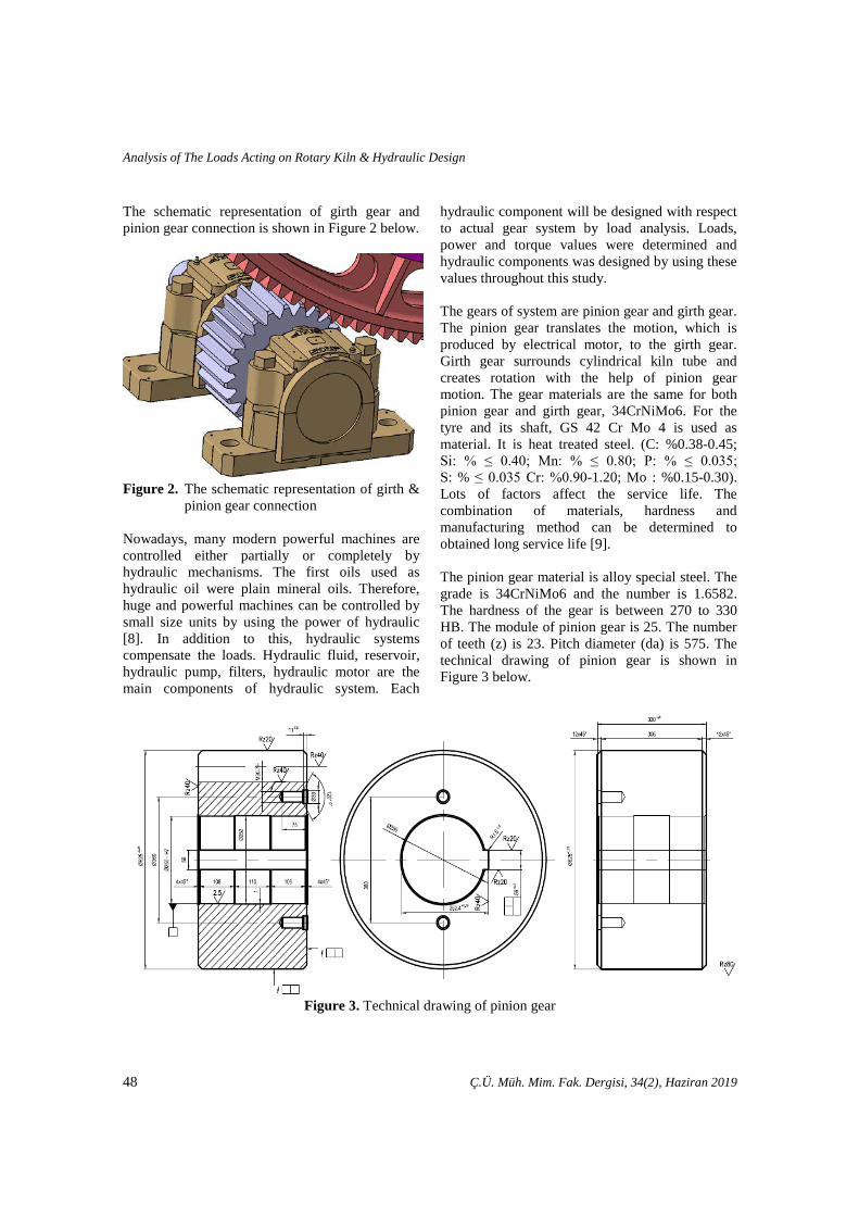
The schematic representation of girth gear and pinion gear connection is shown in Figure 2 below.
Figure 2. The schematic representation of girth &
pinion gear connection Nowadays, many modern powerful machines are controlled either partially or completely by hydraulic mechanisms. The first oils used as hydraulic oil were plain mineral oils. Therefore, huge and powerful machines can be controlled by small size units by using the power of hydraulic [8]. In addition to this, hydraulic systems compensate the loads. Hydraulic fluid, reservoir, hydraulic pump, filters, hydraulic motor are the main components of hydraulic system. Each
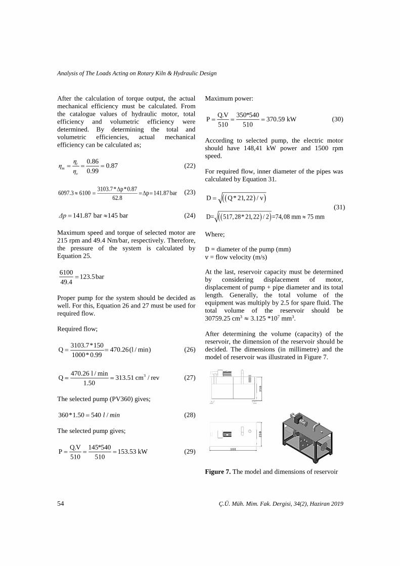
hydraulic component will be designed with respect to actual gear system by load analysis. Loads, power and torque values were determined and hydraulic components was designed by using these values throughout this study. The gears of system are pinion gear and girth gear. The pinion gear translates the motion, which is produced by electrical motor, to the girth gear. Girth gear surrounds cylindrical kiln tube and creates rotation with the help of pinion gear motion. The gear materials are the same for both pinion gear and girth gear, 34CrNiMo6. For the tyre and its shaft, GS 42 Cr Mo 4 is used as material. It is heat treated steel. (C: %0.38-0.45; Si: % ≤ 0.40; Mn: % ≤ 0.80; P: % ≤ 0.035; S: % ≤ 0.035 Cr: %0.90-1.20; Mo : %0.15-0.30). Lots of factors affect the service life. The combination of materials, hardness and manufacturing method can be determined to obtained long service life [9]. The pinion gear material is alloy special steel. The grade is 34CrNiMo6 and the number is 1.6582. The hardness of the gear is between 270 to 330 HB. The module of pinion gear is 25. The number of teeth (z) is 23. Pitch diameter (da) is 575. The technical drawing of pinion gear is shown in Figure 3 below.
Figure 3. Technical drawing of pinion gear
48 Ç.Ü. Müh. Mim. Fak. Dergisi, 34(2), Haziran 2019

Sadık ÜNAL, Abdul Kadir EKŞİ
The girth gear material is alloy special steel. The grade is 34CrNiMo6 and the number is 1.6582, too. The hardness of the gear is between 220 to 266 HB. The module of pinion gear is 25 mm. The
number of teeth (z) is 176. Pitch diameter (da) is 4400 mm. The technical drawing of girth gear is shown in Figure 4 below.
Figure 4. Technical drawing of girth gear
The design rotary kiln has 45 meter length and 3 meter diameter with 2o inclination. The dimension between the layers of rotary kiln and 3 tyres and gear are shown in Figure 5. The other name of tyres is riding rings. Tyre is annular single steel part. Tyre is produced by machining to obtain
smooth cylindrical surface. The tyre rides steel rollers and set about half a kiln-diameter apart. The rotary kiln must be supported by tyres and reduce the friction. Tyres are welded with a block to rotary kiln rotating ring.
Figure 5. Technical drawing of rotary kiln
Ç.Ü. Müh. Mim. Fak. Dergisi, 34(2), Haziran 2019 49

Analysis of The Loads Acting on Rotary Kiln & Hydraulic Design
The rotary kiln, which was analyzed and designed, was modeled via CATIA software program in 3D environment. The 3D model of the system was illustrated in Figure 6.
Figure 6. 3D model of the rotary kiln 3.2. Method The modules and number of teeth for pinion and girth gear are given in material section. So, the pitch diameters can be calculated. Also, the analytical calculation of force and torque on the gear can be calculated as follows. The first step of calculation starts with the pitch diameters of gears dr=Nr*m (1) dp=Np*m (2) Where; 𝑑𝑑 is the pitch diameter of the rotary kiln and the pinion (mm), 𝑚𝑚 is the module, N is the number of teeth, Sub-index 𝑟𝑟 and 𝑝𝑝 indicates rotary kiln and pinion, respectively. Calculation of the center diameter of gears the second step of values of force and torque. dr+dp
2=dc (3)
Where; dr is the pitch diameter of rotary kiln, dp is the pitch diameter of pinion, dc is the center diameter. The corresponding equation of transmitted load is expressed by following equation;
60000=t
p p
* HWπ* d * n
(4)
Where; 𝑊𝑊𝑡𝑡 is the transmitted load (kN), 𝐻𝐻 is the power (kW), 𝑛𝑛 is the speed (rev/min), Thus, the tangential force of pinion on rotary kiln is 𝐹𝐹𝑡𝑡 = 𝑊𝑊𝑡𝑡. And force (𝐹𝐹) express as;
cos 20=
t
o
FF (5)
After the calculation of force, torque (T) can be find out as;
2= pd
T F * (6)
For the design of the hydraulic system, it is necessary to know the forces and torque in the gear system. As we have given the force and torque formulas, we can also share hydraulic formulas. Required flow is express as;
V*nQ (l / min)1000
=v
* η
(7)
Torque output is express as;
V*Δp*M (Nm)
62.8= mη
(8)
Output power is express as;
50 Ç.Ü. Müh. Mim. Fak. Dergisi, 34(2), Haziran 2019

Sadık ÜNAL, Abdul Kadir EKŞİ
Q*Δp*P (kW)
600= tη
(9)
Where; V = displacement (cm3/rev), n = speed (rpm), Δp = differential pressure (bar), 𝜂𝜂𝑣𝑣 = volumetric efficiency, 𝜂𝜂𝑚𝑚 = mechanical efficiency, 𝜂𝜂𝑡𝑡 = overall efficiency. Hydraulic Pump is the circuit element that sends the fluid in the tank to the set pressure and outgoing system. The pumps convert mechanical energy into hydraulic energy. The basic principle of hydraulic pumps is Pascal’s Law. The pressure which is applied on hydraulic, transmits everywhere with contacting hydraulic. Hydraulic pumps are positive displacement pumps. Power source is substance of hydraulic, reservoir and hydraulic pump instead of the electrical motor at gear system. Safe working system is obtained with the help of safety valves at hydraulic system. When the pump is selected, it must be selected to produce enough pressure and pressure to perform the function of the system to be used. Varies types of hydraulic pumps are available such as hand, power driven, constant displacement, gear type power, gerotor, piston, vane and variable displacement [10]. The principle of piston pump is reciprocation by rotation unit for producing fluid flow. There is no only single piston, but also piston-cylinder combinations may be used. The mechanism of the pump creates rotation to shaft for generating reciprocating motion. The fluid is drawn into cylinder and fluid expels, so flow is produced. Two different types of piston pump are available, axial and radial piston. In addition to this, both types of pumps have fixed and variable displacement type pumps. Variable displacement piston pumps are generally called overcenter pumps. The gerotor type pumps are in reality generated rotor pumps. Different types of gerotor are
available. The internal-gear gerotor pump has pair of gears and these gears are always in sliding contact. The internal gear has to be one more tooth than the gerotor gear for obtaining sliding contact. All of the gears rotation direction is the same. Chamber is filled with oil before the teeth distancing from each other, and is ejected. The sealing is used by the sliding contact. Gerotor has some advantages and disadvantages and they are shown Table 2 below: Table 2. Precedence and limitations of the
hydraulic gerotor motor Precedence Limitations
Compared to other types of hydraulic motors, relatively
simple construction
Low sealing ability of lobes between the inner
rotor and outer ring
Low speed Low total efficiency Relatively small
and light Friction
Relatively cheap Wear High torque
Self-braking ability For selection of electric motor, maximum power should be calculated. It can be calculated from equation 10 as below:
.510
=QV P (10)
Every hydraulics has different physical properties. Hydraulic fluids are used to transmit hydraulic power. In addition to lubricating and cooling the hydraulic circuit elements. When water is used as a hydraulic fluid, problems such as corrosion, boiling point, freezing point and low viscosity are encountered. The physical properties of hydraulic fluids are very sensitive and important such as viscosity, oxidation, ability of lubrication, bubble formation, yield point, flashing point, and polymerization [11]. For the fluid, the best quality hydraulic mineral fluid is preferable such as HLP oils to DIN 51524. Brugger value should be more than 30 N/mm2 for general application and more than 50 N/mm2 for heavily loaded hydraulic equipment and fast cycling and high dynamic
Ç.Ü. Müh. Mim. Fak. Dergisi, 34(2), Haziran 2019 51

Analysis of The Loads Acting on Rotary Kiln & Hydraulic Design
loaded machines, measured with respect to DIN 51 347-2. The normal operating viscosity should be between 16 and 100 mm2/s (cSt) whereas maximum start-up viscosity should be 800 mm2/s (cSt). Effective filtration should be performed in order to protect the system from contamination for maximum pump and system component functionality and life. The quality can be obtained by obeying standards. For the fluid cleanliness, the system should be suitable to ISO 4406:1999 standard. In addition to this, quality of filter elements should be suitable to such as class 20/18/15, with respect to to ISO 4406:1999. Recommended cleanliness class is 18/16/13 for ISO 4406:1999. Therefore, maximum component life and functionality are obtained. Hydraulic fluid specification for chemical resistance of seal material and its temperature must be compared with maximum system temperature and ambient temperature. N- Nitride which is able to resist between -40…+90 oC are preferable [12]. Inner diameter of the pipe can be calculated from equation 11 as below:
( )( )21.22 /=D Q* v (11) 𝐷𝐷 = diameter of the pump (mm) 𝑣𝑣 = flow velocity (m/s) The last component that should be calculated on the system is the reservoir. The reservoir capacity should be more than the volume of motor displacement, pump displacement and pipes in the system. 3. RESULTS The pitch diameters of gears were calculated as 575 mm for pinion and 4400 mm for rotary gears. The equations are presented in Equation 12 and 13, respectively.
176 25 4400= = =r rd N * m * mm (12)
23 25 575= = =p pd N * m * mm (13) The center diameter of the gears is calculated by Equation 14.
4400 575 2487.52 2+ +
= =r pd d mm (14)
The corresponding equation of transmitted load is expressed by following equation (7,5 kW electrical motor is neglected, because it is auxiliary drive). Calculations are made with respect to main drive (90 kW electrical motor);
60000 60000 90.0575 150
= =tp p
* H *Wπ* d * n π* *
19.929kN=tW
(15)
Thus, the tangential force of pinion on rotary kiln is Wt=𝐹𝐹𝑡𝑡 = 19,929 kN. Therefore, force can be calculated as;
19.929 21.208kNcos 20 cos 20
= = =t
o o
FF (16)
Torque 𝑇𝑇 of the gear is can be calculated as;
T=F*dp
2=21.208*
5752
=6097.3 N.mm (17)
After the calculation of force and torque, the motor capacity, pump capacity, electric motor and reservoir can be evaluated.
Required flow;
(l / min)1000
=v
V * nQ * η
(18)
Torque output;
(Nm)62.8
= mV * Δp* ηM (19)
52 Ç.Ü. Müh. Mim. Fak. Dergisi, 34(2), Haziran 2019

Sadık ÜNAL, Abdul Kadir EKŞİ
Output power;
(kW)600
= tQ* Δp* ηP (20)
V = displacement (cm3/rev) n = speed (rpm) Δp = differential pressure (bar) 𝜂𝜂𝑣𝑣 = volumetric efficiency 𝜂𝜂𝑚𝑚 = mechanical efficiency 𝜂𝜂𝑡𝑡 = overall efficiency Generally, mechanical efficiency is assumed 0,9 at mechanical systems. By assuming the system mechanical efficiency as 0,9 torque output formula, 𝑉𝑉 ∗ 𝛥𝛥𝑝𝑝 can be calculated as;
V * p*0,9 6097.3 6100 V * p 425644.4 Nm62.8∆
≈ = = ∆ = (21)
The selection hydraulic motor must be confirmed the value of 425644.4 Nm. The different type of hydraulic motors can be selected in table from MR 1800 H to MRE 5400 L. But for example, at MR2400 H must be Flushing. Minimum MR2400 I can be selected, but minimum two size of larger can be selected for working in safe area. According to calculations, the motor from 1800 H to MRE 5400 L can be used. However, in order to avoid flushing, the motor MR 2400 I and the rest should be selected. To be more secure, in this study, MRE 3100 I was selected as motor. The diagrams of the motor MRA 2400 H, MR 2400 H and MRE 3100 I were presented in Table 3 below [13].
Table 3. Hydraulic motor selection chart
Ç.Ü. Müh. Mim. Fak. Dergisi, 34(2), Haziran 2019 53
Analysis of The Loads Acting on Rotary Kiln & Hydraulic Design
After the calculation of torque output, the actual mechanical efficiency must be calculated. From the catalogue values of hydraulic motor, total efficiency and volumetric efficiency were determined. By determining the total and volumetric efficiencies, actual mechanical efficiency can be calculated as;
0.86 0.870.99
= = =tm
v
ηη
η (22)
3103.7* p*0.876097.3 6100 p 141.87 bar
62.8∆
≈ = =∆ = (23)
141.87 ba 1 45r bar= ≈Δp (24)
Maximum speed and torque of selected motor are 215 rpm and 49.4 Nm/bar, respectively. Therefore, the pressure of the system is calculated by Equation 25. 6100 123.5bar49.4
=
Proper pump for the system should be decided as well. For this, Equation 26 and 27 must be used for required flow. Required flow;
3103.7 150Q 470.26(l / min)1000 0.99
= =*
* (26)
3470.26 l / minQ 313.51 cm / rev
1.50= = (27)
The selected pump (PV360) gives; 360 1.50 540 /=* l min (28) The selected pump gives;
Q.V 145*540P 153.53 kW510 510
= = = (29)
Maximum power:
Q.V 350*540P 370.59 kW510 510
= = = (30)
According to selected pump, the electric motor should have 148,41 kW power and 1500 rpm speed. For required flow, inner diameter of the pipes was calculated by Equation 31.
( )( )D Q 21,22 / v= *
( )( )D= 517,28 21,22 / 2 74,08 mm 7 mm= 5 ≈* (31)
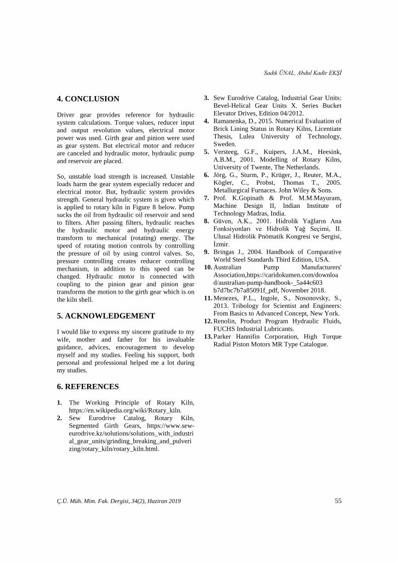
Where; D = diameter of the pump (mm) v = flow velocity (m/s) At the last, reservoir capacity must be determined by considering displacement of motor, displacement of pump + pipe diameter and its total length. Generally, the total volume of the equipment was multiply by 2.5 for spare fluid. The total volume of the reservoir should be 30759.25 cm3 ≈ 3.125 *107 mm3. After determining the volume (capacity) of the reservoir, the dimension of the reservoir should be decided. The dimensions (in millimetre) and the model of reservoir was illustrated in Figure 7.
Figure 7. The model and dimensions of reservoir
54 Ç.Ü. Müh. Mim. Fak. Dergisi, 34(2), Haziran 2019
Sadık ÜNAL, Abdul Kadir EKŞİ
4. CONCLUSION Driver gear provides reference for hydraulic system calculations. Torque values, reducer input and output revolution values, electrical motor power was used. Girth gear and pinion were used as gear system. But electrical motor and reducer are canceled and hydraulic motor, hydraulic pump and reservoir are placed. So, unstable load strength is increased. Unstable loads harm the gear system especially reducer and electrical motor. But, hydraulic system provides strength. General hydraulic system is given which is applied to rotary kiln in Figure 8 below. Pump sucks the oil from hydraulic oil reservoir and send to filters. After passing filters, hydraulic reaches the hydraulic motor and hydraulic energy transform to mechanical (rotating) energy. The speed of rotating motion controls by controlling the pressure of oil by using control valves. So, pressure controlling creates reducer controlling mechanism, in addition to this speed can be changed. Hydraulic motor is connected with coupling to the pinion gear and pinion gear transforms the motion to the girth gear which is on the kiln shell. 5. ACKNOWLEDGEMENT I would like to express my sincere gratitude to my wife, mother and father for his invaluable guidance, advices, encouragement to develop myself and my studies. Feeling his support, both personal and professional helped me a lot during my studies. 6. REFERENCES 1. The Working Principle of Rotary Kiln,
https://en.wikipedia.org/wiki/Rotary_kiln. 2. Sew Eurodrive Catalog, Rotary Kiln,
Segmented Girth Gears, https://www.sew-eurodrive.kz/solutions/solutions_with_industrial_gear_units/grinding_breaking_and_pulverizing/rotary_kiln/rotary_kiln.html.
3. Sew Eurodrive Catalog, Industrial Gear Units: Bevel-Helical Gear Units X. Series Bucket Elevator Drives, Edition 04/2012.
4. Ramanenka, D., 2015. Numerical Evaluation of Brick Lining Status in Rotary Kilns, Licentiate Thesis, Lulea University of Technology, Sweden.
5. Versteeg, G.F., Kuipers, J.A.M., Heesink, A.B.M., 2001. Modelling of Rotary Kilns, University of Twente, The Netherlands.
6. Jörg, G., Sturm, P., Krüger, J., Reuter, M.A., Kögler, C., Probst, Thomas T., 2005. Metallurgical Furnaces. John Wiley & Sons.
7. Prof. K.Gopinath & Prof. M.M.Mayuram, Machine Design II, Indian Institute of Technology Madras, India.
8. Güven, A.K., 2001. Hidrolik Yağların Ana Fonksiyonları ve Hidrolik Yağ Seçimi, II. Ulusal Hidrolik Pnömatik Kongresi ve Sergisi, İzmir.
9. Bringas J., 2004. Handbook of Comparative World Steel Standards Third Edition, USA.
10. Australian Pump Manufacturers' Association,https://caridokumen.com/download/australian-pump-handbook-_5a44c603 b7d7bc7b7a85091f_pdf, November 2018.
11. Menezes, P.L., Ingole, S., Nosonovsky, S., 2013. Tribology for Scientist and Engineers: From Basics to Advanced Concept, New York.
12. Renolin, Product Program Hydraulic Fluids, FUCHS Industrial Lubricants.
13. Parker Hannifin Corporation, High Torque Radial Piston Motors MR Type Catalogue.
Ç.Ü. Müh. Mim. Fak. Dergisi, 34(2), Haziran 2019 55

Analysis of The Loads Acting on Rotary Kiln & Hydraulic Design
56 Ç.Ü. Müh. Mim. Fak. Dergisi, 34(2), Haziran 2019