antenna downtilt
DESCRIPTION
Antenna downtiltTRANSCRIPT
macrocellular site and antenna configurations for electrical and mechanical antenna downtilt concepts. The aim
of this massive simulation campaign was expected to provide an answer to two questions: firstly, how to selected
depending on the network configuration. Moreover, the corresponding downlink capacity gains varied between
the simulation results revealed how the importance of the antenna downtilt becomes more significant in dense
the definition of antenna configuration, and especially, antenna downtilt angle. By utilizing antenna downtilt,
+358-3-3115 4749; fax: +358-3-3115 3808; e-mail: [email protected]).The target of topology planning is to optimize site and antenna configuration in such a manner that cells become as isolated as possible.
to coverage problems at cell border areas. Therefore, it is vital to define an optimum downtilt angle separately
for each site and antenna configuration.
It has been observed to be an efficient method to reduce other-cell interference in the main-lobe direction [
ıs reduction of other-cell interference affects especially in macrocellular WCDMA
], optimum EDT angles have been defined site-by-site basis using
capacity gain up to 15% with practical macrocellular network configurations. Naturally, an increasing impact
evaluate optimum downtilt angles for different practical base station site and antenna configurations for suburban
all simulated network configurations.

Furthermore, the network (or cell) capacity is defined by the load equations that, on the other hand, set limits
for the maximum number of users in a cell or for the maximum cell throughput. The system capacity is defined
in this context as the maximum number of users that can be supported simultaneously with a pre-defined service
th mobile to the base station. The maximum uplink capacity is defined by the uplink load factor,
The load factor is used to define a radio network planning parameter called interference margin
be fulfilled:
is the downlink traffic channel (TCH) TX power for the
(CPICH), other common channels (CCCH), and traffic channels as well. The total transmit power
, is defined with the aid of the average transmit power of TCHs of base stations
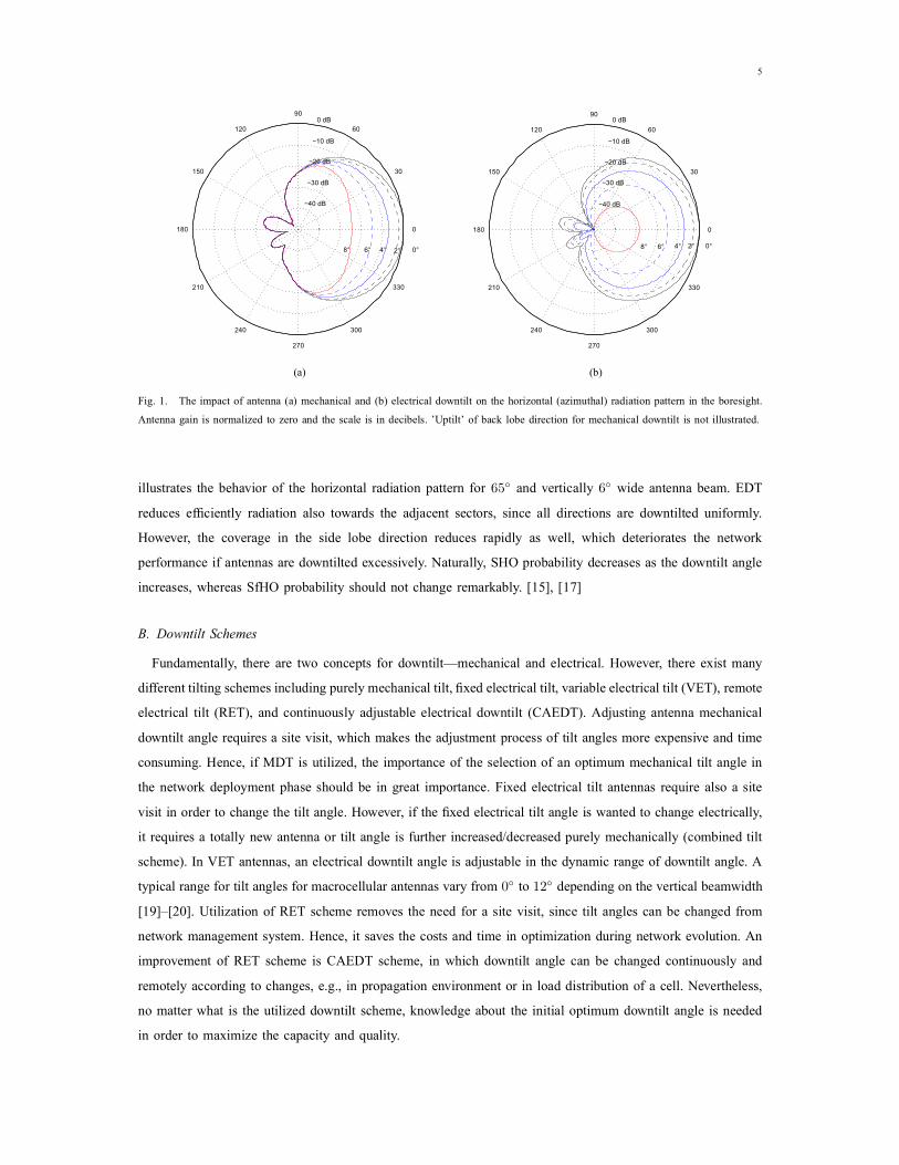
reduces efficiently radiation also towards the adjacent sectors, since all directions are downtilted uniformly.
different tilting schemes including purely mechanical tilt, fixed electrical tilt, variable electrical tilt (VET), remote
visit in order to change the tilt angle. However, if the fixed electrical tilt angle is wanted to change electrically,

The selection of antenna downtilt angle depends on the site and antenna configuration, and hence it has to
geometrical factor as such is not enough to define the required downtilt angle, as it does not take into account
A. Network Configuration
The impact of different network configurations on the optimum downtilt angles is simulated by using a static
For the system level analysis, a macrocellular network is configured in a shape of a regular hexagonal grid of
]. Finally, the selected site and antenna configurations are the following
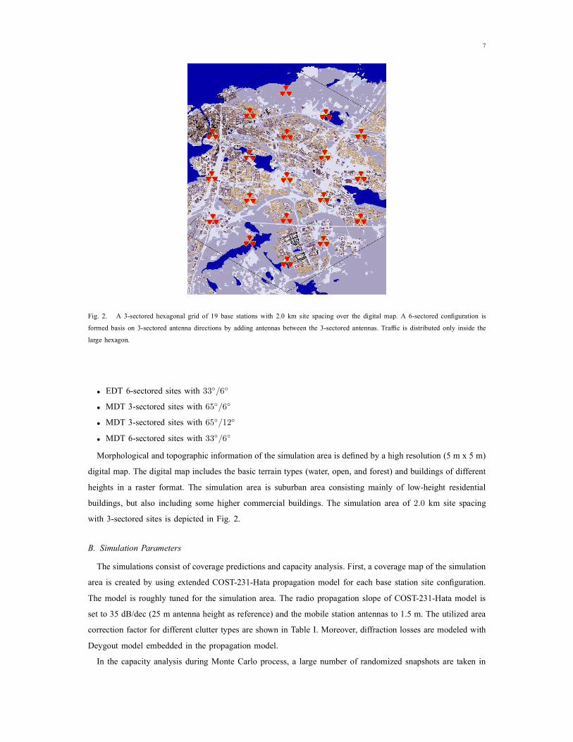
A 3-sectored hexagonal grid of 19 base stations with 2.0 km site spacing over the digital map. A 6-sectored configuration is
formed basis on 3-sectored antenna directions by adding antennas between the 3-sectored antennas. Traffic is distributed only inside the
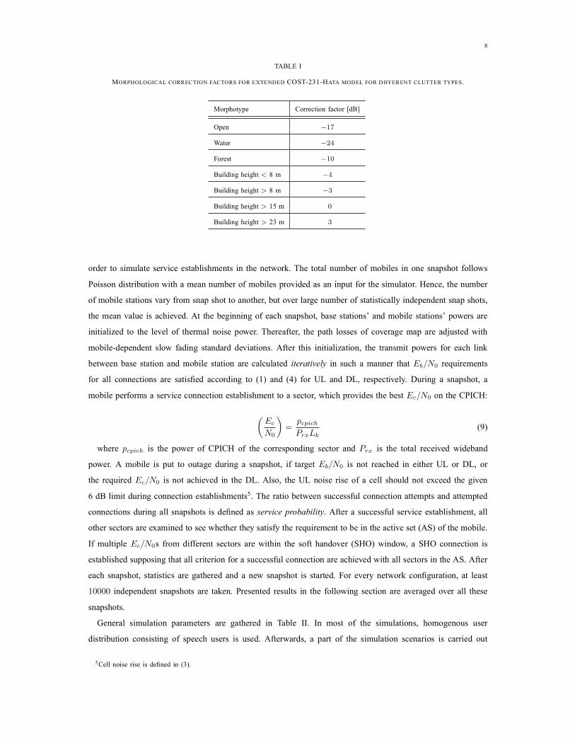
Morphological and topographic information of the simulation area is defined by a high resolution (5 m x 5 m)
area is created by using extended COST-231-Hata propagation model for each base station site configuration.
for all connections are satisfied according to (
connections during all snapshots is defined as
each snapshot, statistics are gathered and a new snapshot is started. For every network configuration, at least
Cell noise rise is defined in (

BS noise figure [dB]
by using a traffic mix of speech and data users with a nonuniform distribution. Table
Every site and antenna configuration is simulated with two different traffic volumes (referred to as low and
configuration. Note that the target is not to seek the same downtilt angle for a part of a network, but to find an
optimum downtilt angle depending on the site and antenna configuration. The definition of an optimum downtilt
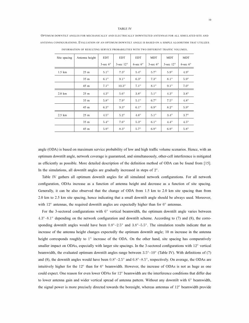
angle (ODA) is based on maximum service probability of low and high traffic volume scenarios. Hence, with an
as efficiently as possible. More detailed description of the definition method of ODA can be found from [
gathers all optimum downtilt angles for all simulated network configurations. For all network
configuration, ODAs increase as a function of antenna height and decrease as a function of site spacing.
For the 3-sectored configurations with
depending on the network configuration and downtilt scheme. According to (
smaller impact on ODAs, especially with larger site spacings. In the 3-sectored configurations with
). With definitions of (

(a) Service probability and (b) DL load for the 3-sectored network configuration under high traffic volume. The network configuration
configurations with 1.5 km site spacing and 25 m antenna height under high traffic volume scenario. Moreover,
beamwidth is more efficient coverage reduction (see Section V.C). However, with 12
beamwidth the coverage reduction is not that efficient due to the wider vertical beam, but ODA is limited by
this particular traffic volume at maximum by
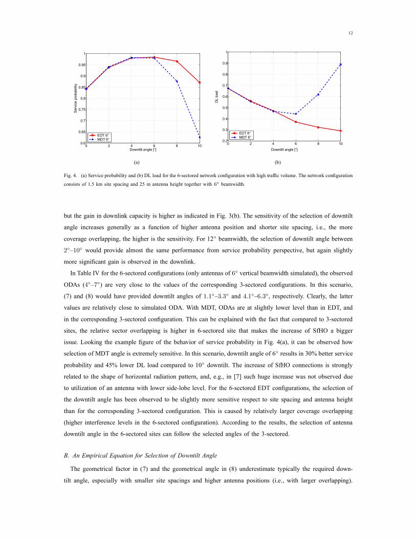
(a) Service probability and (b) DL load for the 6-sectored network configuration with high traffic volume. The network configuration
more significant gain is observed in the downlink.
for the 6-sectored configurations (only antennas of
) are very close to the values of the corresponding 3-sectored configurations. In this scenario,
in the corresponding 3-sectored configuration. This can be explained with the fact that compared to 3-sectored
issue. Looking the example figure of the behavior of service probability in Fig.
to utilization of an antenna with lower side-lobe level. For the 6-sectored EDT configurations, the selection of
than for the corresponding 3-sectored configuration. This is caused by relatively larger coverage overlapping
(higher interference levels in the 6-sectored configuration). According to the results, the selection of antenna
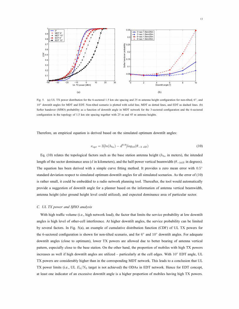
(a) UL TX power distribution for the 6-sectored 1.5 km site spacing and 25 m antenna height configuration for non-tilted,
Softer handover (SfHO) probability as a function of downtilt angle in MDT network for the 3-sectored configuration and the 6-sectored
configuration in the topology of 1.5 km site spacing together with 25 m and 45 m antenna heights.
The equation has been derived with a simple curve fitting method. It provides a zero mean error with
With high traffic volume (i.e., high network load), the factor that limits the service probability at low downtilt
the 6-sectored configuration is shown for non-tilted scenario, and for
the 6-sectored configurations with 25 m and 45 m antenna heights, and with 1.5 km site spacing. The increase
is more significant after
overhead becomes more significant also with higher antenna position after downtilt angle of
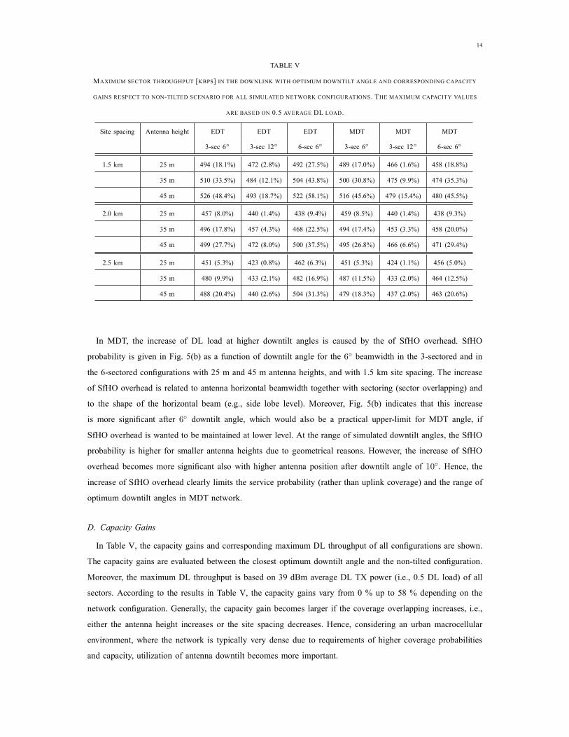
, the capacity gains and corresponding maximum DL throughput of all configurations are shown.
The capacity gains are evaluated between the closest optimum downtilt angle and the non-tilted configuration.
network configuration. Generally, the capacity gain becomes larger if the coverage overlapping increases, i.e.,
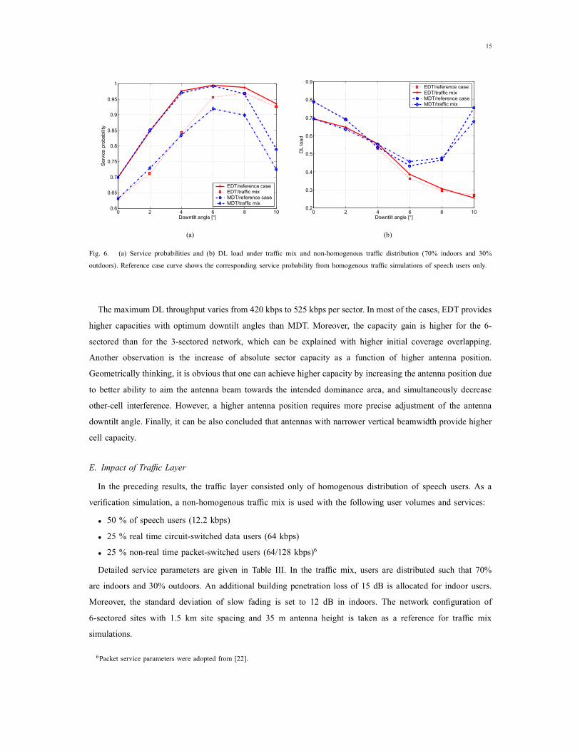
(a) Service probabilities and (b) DL load under traffic mix and non-homogenous traffic distribution (70% indoors and 30%
outdoors). Reference case curve shows the corresponding service probability from homogenous traffic simulations of speech users only.
E. Impact of Traffic Layer
In the preceding results, the traffic layer consisted only of homogenous distribution of speech users. As a
verification simulation, a non-homogenous traffic mix is used with the following user volumes and services:
. In the traffic mix, users are distributed such that 70%
Moreover, the standard deviation of slow fading is set to 12 dB in indoors. The network configuration of
6-sectored sites with 1.5 km site spacing and 35 m antenna height is taken as a reference for traffic mix

shows the average service probabilities under high user volume traffic
the corresponding DL loads. Under the traffic mix, the optimum downtilt angles for MDT
increase of SfHO connections obviously limits the ODA in MDT network independent of the traffic mix. On
the traffic or its distribution does not affect the optimum downtilt angle.
An optimum downtilt angle, which is defined by the site spacing, antenna height and vertical beamwidth,
has been found for numerous practical network configurations. Within the range of typical macrocellular
network configurations (site spacings of 1.5 km–2.5 km, antenna heights of 25 m–45 m, and antenna vertical
traffic distribution. The sectoring scheme (3-sectored or 6-sectored) and tilting concept (MDT or EDT) affect
mean larger proportion of mobiles benefitting from the SHO gain. On the other hand, e.g., in [
The traffic distribution between outdoor and indoor or traffic mix was not observed to have notable impact
different traffic volumes, it is heavily assumed that the optimum downtilt angle is more sensitive to changes
J. Wu, J. Chung, C. Wen, ”Hot-spot traffic relief with a tilted antenna in CDMA cellular networks,”
J. Laiho-Steffens, A. Wacker, P. Aikio, ”The impact of the radio network planning and site configuration on the WCDMA network
a, ”Impact of base station and antenna configuration on capacity in WCDMA cellular networks,” M. Sc. Thesis, Tampere