appendix d.1 parametric study mathcad calculation...
TRANSCRIPT

Appendix D.1
Parametric Study MathCAD Calculation Sheets

MathCAD Example Templates for AASHTO Design Calculations
Table of Contents
Metal Arch AASHTO Design 20.1x9………………………………………………2
Metal Arch AASHTO Design 30.1x18……………………………………………..4
Metal Arch AASHTO Standard Design 20.1x9…………………………………… 6
Metal Arch AASHTO Standard Design 30.1x18………………………………….. 8
Metal Arch AASHTO Proposed Simple Equation 20.1x9………………………… 10
Metal Arch AASHTO Proposed Simple Equation 30.1x18……………………….. 13
Profile Wall 24” – CL85 AASHTO Design……………………………………….. 16
Profile Wall 24” – CL85 AASHTO Standard Design……………………………... 19
Profile Wall 24” – CL85 AASHTO Proposed Simple Equation…………………... 22
RCP AASHTO Design Type 1…………………………………………………….. 25
RCP AASHTO Standard Design Type 1…………………………………………...30
RCP AASHTO Proposed Simple Equation………………………………………... 35
CMP 24” AASHTO Design………………………………………………………...40
CMP 24” AASHTO Standard Design………………………………………………42
CMP 24” AASHTO Proposed Simple Equation…………………………………... 44

CONSULTING ENGINEERS2800 UNIVERSITY AVE SEMINNEAPOLIS, MN 55414
CNAPhone: (612) 379-8805
Fax: (612) 379-8160
CLIENT PROJECT: NCHRP
CALCULATION BY: GL DATE: 9/14/2007
APPROVED BY: CRN DATE: 9/14/2007
OBJECT : Metal Arch - AASHTO LRFD Design_20.1X9
SOURCE: AASHTO LRFD Bridge Design Specifications_________________________________________________________________________________________________
Units
lb lbf psilb
in2kip 1000lbf ksi
kip
in2plf
lbfft
psflbf
ft2pcf
lbf
ft3
Define Variables and Input Design Values
w = unit weight of soil (pcf) w 120
H = Height of fill over pipe (ft.) H 2
S = Span (ft.) S 20.083
R = Rise (ft.) R 9.083
Ru = Upper rise (ft.) Ru 6.5
Rt = Top radius (ft.) Rt 13.083
top = Top angle (deg.) top 80
S/R = Span/ Rise Ratio SR
2.21
LL = total live load applied at surface (lb.) LL 16000
Wt = width of tire (in.) Wt 20
Lt = length of tire parallel to span of culvert (in) Lt 10
LLDF = rate of increase of load spread with increasing depth of fill
LLDF 1.15
whsp 6whsp = wheel spacing (ft.)
LFl 1.75LFl = live load factor
LFd 1.95LFd = dead load factor
SHEET 1 OF 2Page 2 of 46

Total Applied load Values
Soil Unit Weight
We = Crown load (lb/ft) We w H S We 4819.92
Wheel Unit Load (Live Load) (Service load)
Hint = Wheel interaction depth (ft.) Hint
whspWt
12LLDF
Hint 3.77
ALL = Distributed Area (ft2)ALL
Wt
12LLDF H
Lt
12LLDF H H Hintif
Wt
12whsp LLDF H
Lt
12LLDF H H Hintif
ALL 12.43
WLL = live load pressure (lb/ft2) WLLLLALL
H Hintif
2 LLALL
H Hintif WLL 1287.32
Lt.gov = Select controlling load length (ft.) Lt.govLt
12H .82if
Lt
12LLDF H otherwise
Mmpf = Multiple Presence Factor Mmpf 1.2
IM = Dynamic Load Allowance IM1 331 0.125 H
100
IM 331 0.125 H
100H 8if
0 H 8ifIM 0.25
WL = Service Live Load (lb/ft) WL Mmpf 1 IM( ) WLL min S Lt.gov WL 6038.32
Total Service and Factor Load
Wts = Total Service Load (lb/ft) Wts We WL Wts 10858.2
Wtf LFd We LFl WL Wtf 19965.9Wtf = Total Factor Load (lb/ft)
Factored Thrust ValuesTL
Wtf
2TL = Factored thrust per unit length (lb/ft.) TL 9982.95
SHEET 2 OF 2Page 3 of 46

CONSULTING ENGINEERS2800 UNIVERSITY AVE SEMINNEAPOLIS, MN 55414
CNAPhone: (612) 379-8805
Fax: (612) 379-8160
CLIENT PROJECT: NCHRP
CALCULATION BY: GL DATE: 9/14/2007
APPROVED BY: CRN DATE: 9/14/2007
OBJECT : Metal Arch - AASHTO LRFD Design_30.1X18
SOURCE: AASHTO LRFD Bridge Design Specifications_________________________________________________________________________________________________
Units
lb lbf psilb
in2kip 1000lbf ksi
kip
in2plf
lbfft
psflbf
ft2pcf
lbf
ft3
Define Variables and Input Design Values
w = unit weight of soil (pcf) w 120
H = Height of fill over pipe (ft.) H 2
S = Span (ft.) S 30.083
R = Rise (ft.) R 18
Ru = Upper rise (ft.) Ru 10.083
Rt = Top radius (ft.) Rt 19.417
top = Top angle (deg.) top 80
S/R = Span/ Rise Ratio SR
1.67
LL = total live load applied at surface (lb.) LL 16000
Wt = width of tire (in.) Wt 20
Lt = length of tire parallel to span of culvert (in) Lt 10
LLDF = rate of increase of load spread with increasing depth of fill
LLDF 1.15
whsp 6whsp = wheel spacing (ft.)
LFl 1.75LFl = live load factor
LFd 1.95LFd = dead load factor
SHEET 1 OF 2Page 4 of 46
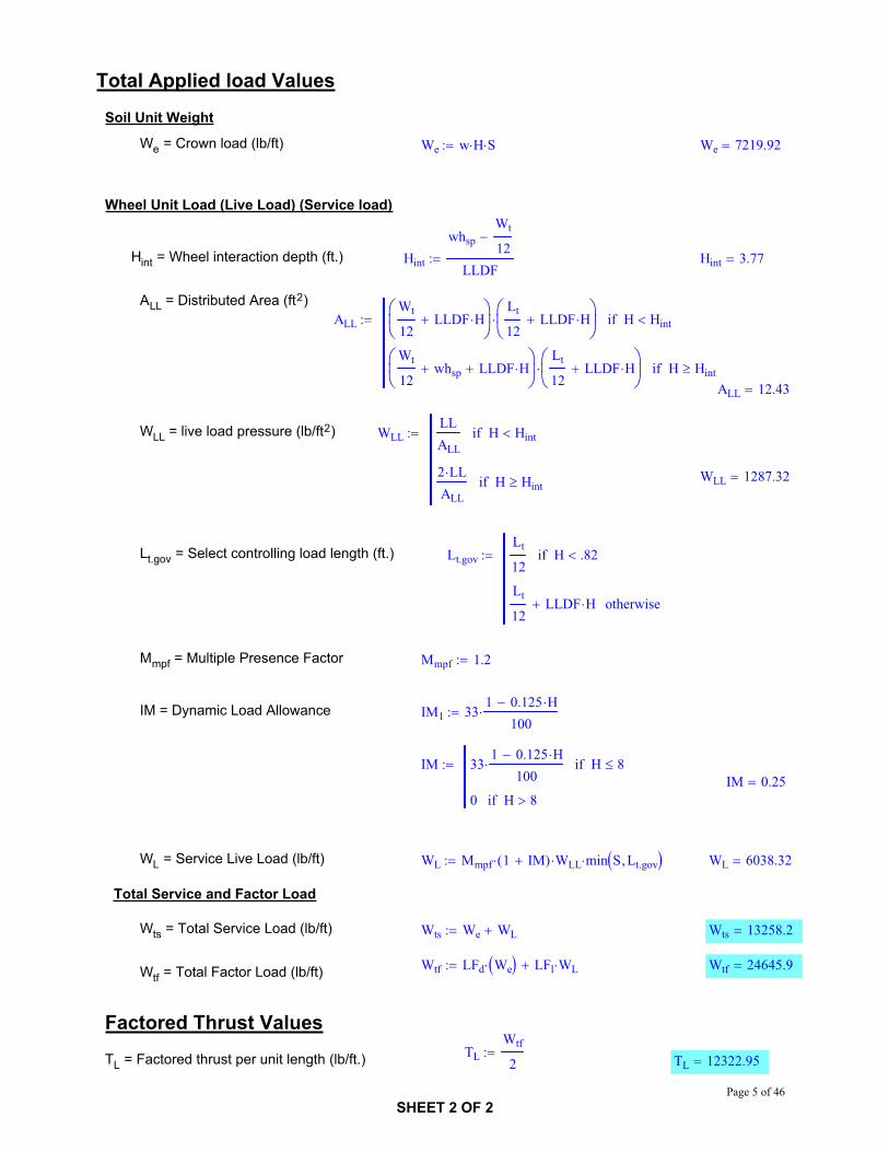
Total Applied load Values
Soil Unit Weight
We = Crown load (lb/ft) We w H S We 7219.92
Wheel Unit Load (Live Load) (Service load)
Hint = Wheel interaction depth (ft.) Hint
whspWt
12LLDF
Hint 3.77
ALL = Distributed Area (ft2)ALL
Wt
12LLDF H
Lt
12LLDF H H Hintif
Wt
12whsp LLDF H
Lt
12LLDF H H Hintif
ALL 12.43
WLL = live load pressure (lb/ft2) WLLLLALL
H Hintif
2 LLALL
H Hintif WLL 1287.32
Lt.gov = Select controlling load length (ft.) Lt.govLt
12H .82if
Lt
12LLDF H otherwise
Mmpf = Multiple Presence Factor Mmpf 1.2
IM = Dynamic Load Allowance IM1 331 0.125 H
100
IM 331 0.125 H
100H 8if
0 H 8ifIM 0.25
WL = Service Live Load (lb/ft) WL Mmpf 1 IM( ) WLL min S Lt.gov WL 6038.32
Total Service and Factor Load
Wts = Total Service Load (lb/ft) Wts We WL Wts 13258.2
Wtf LFd We LFl WL Wtf 24645.9Wtf = Total Factor Load (lb/ft)
Factored Thrust ValuesTL
Wtf
2TL = Factored thrust per unit length (lb/ft.) TL 12322.95
SHEET 2 OF 2Page 5 of 46

CONSULTING ENGINEERS2800 UNIVERSITY AVE SEMINNEAPOLIS, MN 55414
CNAPhone: (612) 379-8805
Fax: (612) 379-8160
CLIENT PROJECT: NCHRP
CALCULATION BY: GL DATE: 9/14/2007
APPROVED BY: CRN DATE: 9/14/2007
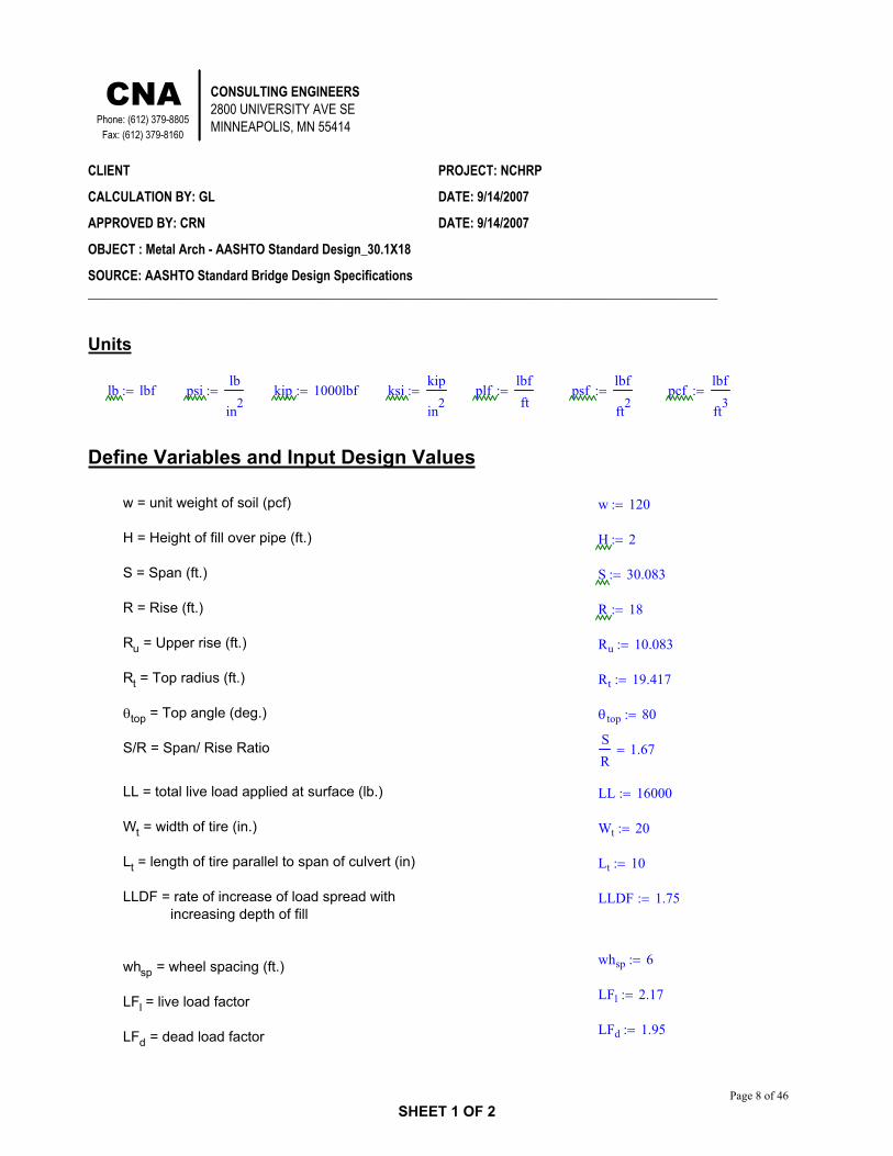
OBJECT : Metal Arch - AASHTO Standard Design_20.1X9
SOURCE: AASHTO Standard Bridge Design Specifications_________________________________________________________________________________________________
Units
lb lbf psilb
in2kip 1000lbf ksi
kip
in2plf
lbfft
psflbf
ft2pcf
lbf
ft3
Define Variables and Input Design Values
w = unit weight of soil (pcf) w 120
H = Height of fill over pipe (ft.) H 2
S = Span (ft.) S 20.083
R = Rise (ft.) R 9.083
Ru = Upper rise (ft.) Ru 6.5
Rt = Top radius (ft.) Rt 13.083
top = Top angle (deg.) top 80
S/R = Span/ Rise Ratio SR
2.21
LL = total live load applied at surface (lb.) LL 16000
Wt = width of tire (in.) Wt 20
Lt = length of tire parallel to span of culvert (in) Lt 10
LLDF = rate of increase of load spread with increasing depth of fill
LLDF 1.75
whsp 6whsp = wheel spacing (ft.)
LFl 2.17LFl = live load factor
LFd 1.95LFd = dead load factor
SHEET 1 OF 2Page 6 of 46
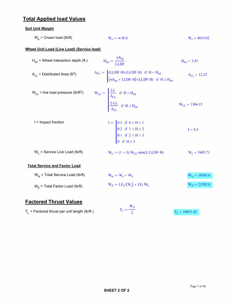
Total Applied load Values
Soil Unit Weight
We = Crown load (lb/ft) We w H S We 4819.92
Wheel Unit Load (Live Load) (Service load)
Hint = Wheel interaction depth (ft.) Hintwhsp
LLDFHint 3.43
ALL LLDF H( ) LLDF H( ) H Hintif
whsp LLDF H LLDF H( ) H HintifALL = Distributed Area (ft2) ALL 12.25
WLL = live load pressure (lb/ft2) WLLLLALL
H Hintif
2 LLALL
H Hintif WLL 1306.12
I = Impact fraction I 0.3 0 H 1if
0.2 1 H 2if
0.1 2 H 3if
0 H 3if
I 0.2
WL = Service Live Load (lb/ft) WL 1 I( ) WLL min S LLDF H( ) WL 5485.71
Total Service and Factor Load
Wts = Total Service Load (lb/ft) Wts We WL Wts 10305.6
Wtf LFd We LFl WL Wtf 21302.8Wtf = Total Factor Load (lb/ft)
Factored Thrust ValuesTL
Wtf
2TL = Factored thrust per unit length (lb/ft.) TL 10651.42
SHEET 2 OF 2Page 7 of 46
CONSULTING ENGINEERS2800 UNIVERSITY AVE SEMINNEAPOLIS, MN 55414
CNAPhone: (612) 379-8805
Fax: (612) 379-8160
CLIENT PROJECT: NCHRP
CALCULATION BY: GL DATE: 9/14/2007
APPROVED BY: CRN DATE: 9/14/2007
OBJECT : Metal Arch - AASHTO Standard Design_30.1X18
SOURCE: AASHTO Standard Bridge Design Specifications_________________________________________________________________________________________________
Units
lb lbf psilb
in2kip 1000lbf ksi
kip
in2plf
lbfft
psflbf
ft2pcf
lbf
ft3
Define Variables and Input Design Values
w = unit weight of soil (pcf) w 120
H = Height of fill over pipe (ft.) H 2
S = Span (ft.) S 30.083
R = Rise (ft.) R 18
Ru = Upper rise (ft.) Ru 10.083
Rt = Top radius (ft.) Rt 19.417
top = Top angle (deg.) top 80
S/R = Span/ Rise Ratio SR
1.67
LL = total live load applied at surface (lb.) LL 16000
Wt = width of tire (in.) Wt 20
Lt = length of tire parallel to span of culvert (in) Lt 10
LLDF = rate of increase of load spread with increasing depth of fill
LLDF 1.75
whsp 6whsp = wheel spacing (ft.)
LFl 2.17LFl = live load factor
LFd 1.95LFd = dead load factor
SHEET 1 OF 2Page 8 of 46

Total Applied load Values
Soil Unit Weight
We = Crown load (lb/ft) We w H S We 7219.92
Wheel Unit Load (Live Load) (Service load)
Hint = Wheel interaction depth (ft.) Hintwhsp
LLDFHint 3.43
ALL LLDF H( ) LLDF H( ) H Hintif
whsp LLDF H LLDF H( ) H HintifALL = Distributed Area (ft2) ALL 12.25
WLL = live load pressure (lb/ft2) WLLLLALL
H Hintif
2 LLALL
H Hintif WLL 1306.12
I = Impact fraction I 0.3 0 H 1if
0.2 1 H 2if
0.1 2 H 3if
0 H 3if
I 0.2
WL = Service Live Load (lb/ft) WL 1 I( ) WLL min S LLDF H( ) WL 5485.71
Total Service and Factor Load
Wts = Total Service Load (lb/ft) Wts We WL Wts 12705.6
Wtf LFd We LFl WL Wtf 25982.8Wtf = Total Factor Load (lb/ft)
Factored Thrust ValuesTL
Wtf
2TL = Factored thrust per unit length (lb/ft.) TL 12991.42
SHEET 2 OF 2Page 9 of 46

CONSULTING ENGINEERS2800 UNIVERSITY AVE SEMINNEAPOLIS, MN 55414
CNAPhone: (612) 379-8805
Fax: (612) 379-8160
CLIENT PROJECT: NCHRP
CALCULATION BY: GL DATE: 9/14/2007
APPROVED BY: CRN DATE: 9/14/2007
OBJECT : Metal Arch - Proposed Simplified Design Eqation_20.1X9
SOURCE:_________________________________________________________________________________________________
Units
lb lbf psilb
in2kip 1000lbf ksi
kip
in2plf
lbfft
psflbf
ft2pcf
lbf
ft3
Define Variables and Input Design Values
w = unit weight of soil (pcf) w 120
H = Height of fill over pipe (ft.) H 2
S = Span (ft.) S 20.083
R = Rise (ft.) R 9.083
Ru = Upper rise (ft.) Ru 6.5
Rt = Top radius (ft.) Rt 13.083
top = Top angle (deg.) top 80
S/R = Span/ Rise Ratio SR
2.21
LL = total live load applied at surface (lb.) LL 16000
Wt = width of tire (in.) Wt 20
Lt = length of tire parallel to span of culvert (in) Lt 10
LLDF = rate of increase of load spread with increasing depth of fill
LLDF 1.15
whsp 6whsp = wheel spacing (ft.)
LFl 1.75LFl = live load factor
LFd 1.95LFd = dead load factor
SHEET 1 OF 3Page 10 of 46
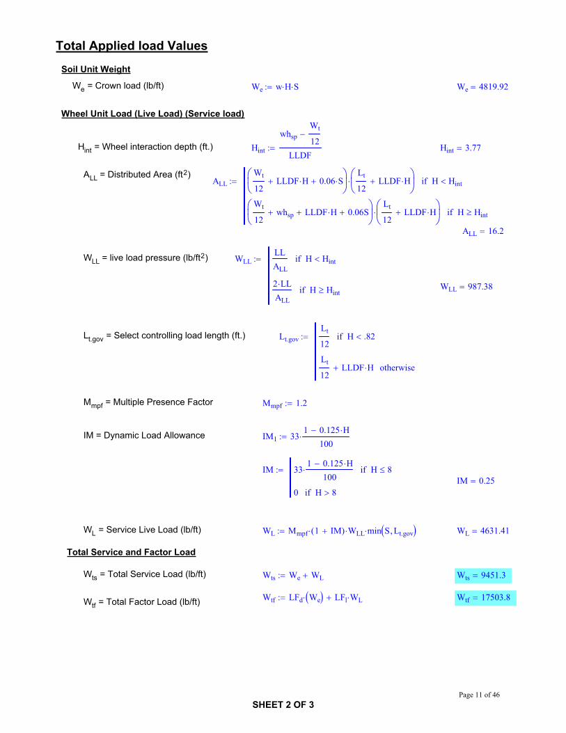
Total Applied load Values
Soil Unit Weight
We = Crown load (lb/ft) We w H S We 4819.92
Wheel Unit Load (Live Load) (Service load)
Hint = Wheel interaction depth (ft.) Hint
whspWt
12LLDF
Hint 3.77
ALL = Distributed Area (ft2)ALL
Wt
12LLDF H 0.06 S
Lt
12LLDF H H Hintif
Wt
12whsp LLDF H 0.06S
Lt
12LLDF H H Hintif
ALL 16.2
WLL = live load pressure (lb/ft2) WLLLLALL
H Hintif
2 LLALL
H Hintif WLL 987.38
Lt.gov = Select controlling load length (ft.) Lt.govLt
12H .82if
Lt
12LLDF H otherwise
Mmpf = Multiple Presence Factor Mmpf 1.2
IM = Dynamic Load Allowance IM1 331 0.125 H
100
IM 331 0.125 H
100H 8if
0 H 8ifIM 0.25
WL = Service Live Load (lb/ft) WL Mmpf 1 IM( ) WLL min S Lt.gov WL 4631.41
Total Service and Factor Load
Wts = Total Service Load (lb/ft) Wts We WL Wts 9451.3
Wtf LFd We LFl WL Wtf 17503.8Wtf = Total Factor Load (lb/ft)
SHEET 2 OF 3Page 11 of 46

Factored Thrust Values
TD = Factored thrust per unit length from dead load (lb/ft.) TDLFd We
2TD 4699.42
Fm,arch = Thrust modifier for long-span metal arches Fm.arch0.54 S
Wt
12LLDF H 0.03 S
Fm.arch 2.37
TL = Factored thrust per unit length from live load (lb/ft.) TLLFl WL
2Fm.arch TL 9618.5
TT = Factored thrust per unit length (lb/ft.) TT TD TL TT 14317.921
SHEET 3 OF 3Page 12 of 46

CONSULTING ENGINEERS2800 UNIVERSITY AVE SEMINNEAPOLIS, MN 55414
CNAPhone: (612) 379-8805
Fax: (612) 379-8160
CLIENT PROJECT: NCHRP
CALCULATION BY: GL DATE: 9/14/2007
APPROVED BY: CRN DATE: 9/14/2007
OBJECT : Metal Arch - Proposed Simplified Design Eqation_30.1X18
SOURCE:_________________________________________________________________________________________________
Units
lb lbf psilb
in2kip 1000lbf ksi
kip
in2plf
lbfft
psflbf
ft2pcf
lbf
ft3
Define Variables and Input Design Values
w = unit weight of soil (pcf) w 120
H = Height of fill over pipe (ft.) H 2
S = Span (ft.) S 30.083
R = Rise (ft.) R 18
Ru = Upper rise (ft.) Ru 10.083
Rt = Top radius (ft.) Rt 19.417
top = Top angle (deg.) top 80
S/R = Span/ Rise Ratio SR
1.67
LL = total live load applied at surface (lb.) LL 16000
Wt = width of tire (in.) Wt 20
Lt = length of tire parallel to span of culvert (in) Lt 10
LLDF = rate of increase of load spread with increasing depth of fill
LLDF 1.15
whsp 6whsp = wheel spacing (ft.)
LFl 1.75LFl = live load factor
LFd 1.95LFd = dead load factor
SHEET 1 OF 3Page 13 of 46
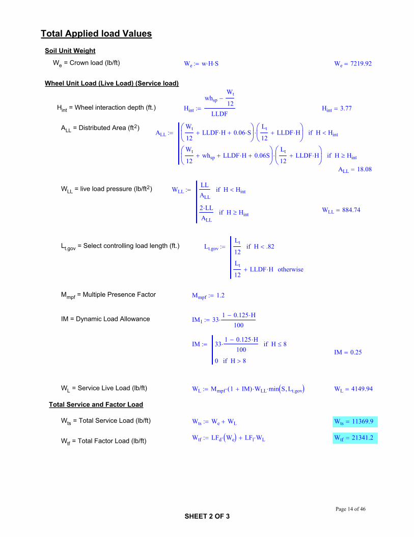
Total Applied load Values
Soil Unit Weight
We = Crown load (lb/ft) We w H S We 7219.92
Wheel Unit Load (Live Load) (Service load)
Hint = Wheel interaction depth (ft.) Hint
whspWt
12LLDF
Hint 3.77
ALL = Distributed Area (ft2)ALL
Wt
12LLDF H 0.06 S
Lt
12LLDF H H Hintif
Wt
12whsp LLDF H 0.06S
Lt
12LLDF H H Hintif
ALL 18.08
WLL = live load pressure (lb/ft2) WLLLLALL
H Hintif
2 LLALL
H Hintif WLL 884.74
Lt.gov = Select controlling load length (ft.) Lt.govLt
12H .82if
Lt
12LLDF H otherwise
Mmpf = Multiple Presence Factor Mmpf 1.2
IM = Dynamic Load Allowance IM1 331 0.125 H
100
IM 331 0.125 H
100H 8if
0 H 8ifIM 0.25
WL = Service Live Load (lb/ft) WL Mmpf 1 IM( ) WLL min S Lt.gov WL 4149.94
Total Service and Factor Load
Wts = Total Service Load (lb/ft) Wts We WL Wts 11369.9
Wtf LFd We LFl WL Wtf 21341.2Wtf = Total Factor Load (lb/ft)
SHEET 2 OF 3Page 14 of 46

Factored Thrust Values
TD = Factored thrust per unit length from dead load (lb/ft.) TDLFd We
2TD 7039.42
Fm,arch = Thrust modifier for long-span metal arches Fm.arch0.54 S
Wt
12LLDF H 0.03 S
Fm.arch 3.34
TL = Factored thrust per unit length from live load (lb/ft.) TLLFl WL
2Fm.arch TL 12114.66
TT = Factored thrust per unit length (lb/ft.) TT TD TL TT 19154.083
SHEET 3 OF 3Page 15 of 46

CONSULTING ENGINEERS2800 UNIVERSITY AVE SEMINNEAPOLIS, MN 55414
CNAPhone: (612) 379-8805
Fax: (612) 379-8160
CLIENT PROJECT: NCHRP
CALCULATION BY: GL DATE: 9/13/2007
APPROVED BY: CRN DATE: 9/13/2007
OBJECT : Profile Wall - AASHTO LRFD Design_cl85
SOURCE: AASHTO LRFD Bridge Design Specifications; ASCE 15-98_________________________________________________________________________________________________
Units
lb lbf psilb
in2kip 1000lbf ksi
kip
in2plf
lbfft
psflbf
ft2pcf
lbf
ft3
Define Variables and Input Design Values
w = unit weight of soil (pcf) w 120
H = Height of fill over pipe (ft.) H 2
Di = inside diameter of pipe (in.) Di 24
h = wall thickness (in.) h 2.16
Do = outside diameter of pipe (in.) Do Di 2 h Do 28.32
Dm = mean diameter of pipe (in.) Dm Di h Dm 26.16
Ap = unit pipe area (in2/in) Ap 0.344
LL = total live load applied at surface (lb.) LL 16000
Wt = width of tire (in.) Wt 20
Lt = length of tire parallel to span of culvert (in) Lt 10
LLDF = rate of increase of load spread with increasing depth of fill
LLDF 1.15
whsp 6whsp = wheel spacing (ft.)
LFl 1.75LFl = live load factor
LFd 1.95LFd = dead load factor
SHEET 1 OF 3Page 16 of 46
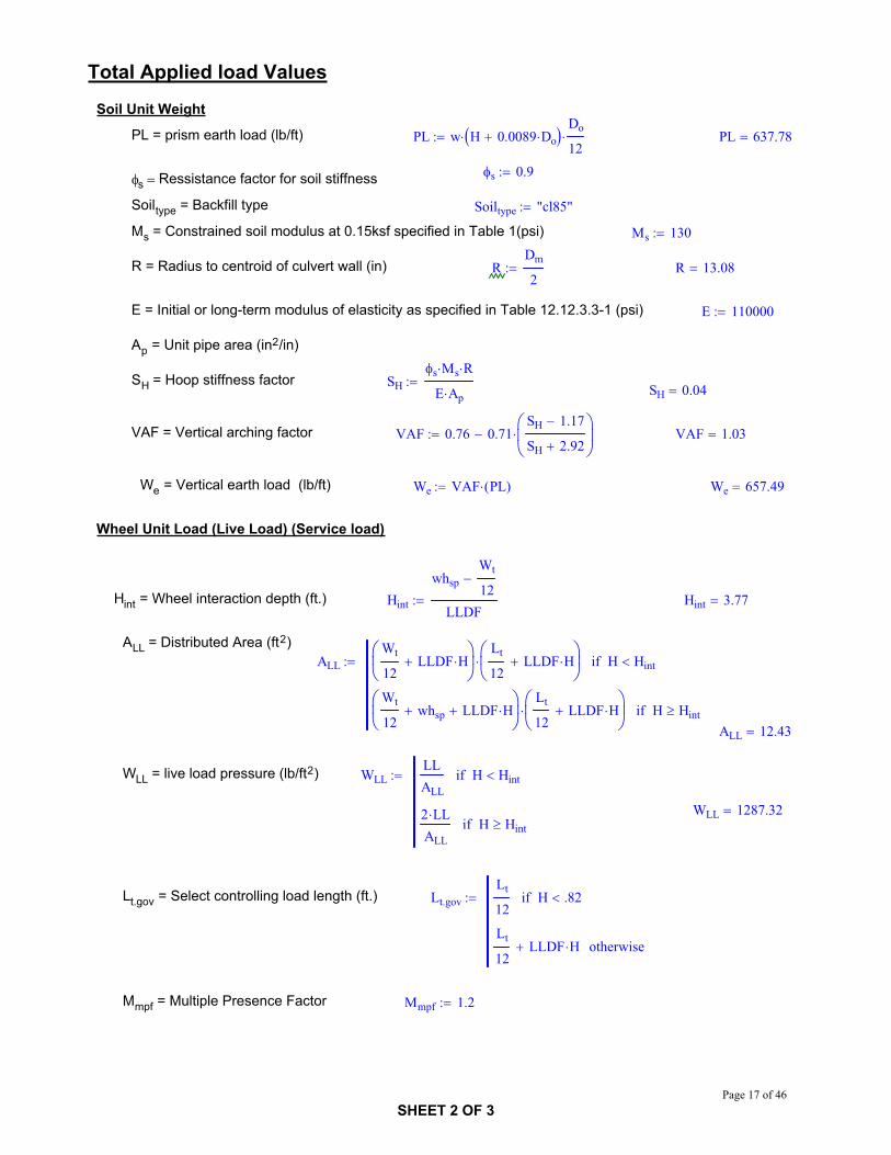
Total Applied load Values
Soil Unit Weight
PL = prism earth load (lb/ft) PL w H 0.0089 DoDo
12PL 637.78
s 0.9s Ressistance factor for soil stiffness
Soiltype = Backfill type Soiltype "cl85"
Ms = Constrained soil modulus at 0.15ksf specified in Table 1(psi) Ms 130
R = Radius to centroid of culvert wall (in) RDm
2R 13.08
E = Initial or long-term modulus of elasticity as specified in Table 12.12.3.3-1 (psi) E 110000
Ap = Unit pipe area (in2/in)
SH = Hoop stiffness factor SHs Ms R
E Ap SH 0.04
VAF = Vertical arching factor VAF 0.76 0.71SH 1.17
SH 2.92VAF 1.03
We = Vertical earth load (lb/ft) We VAF PL( ) We 657.49
Wheel Unit Load (Live Load) (Service load)
Hint = Wheel interaction depth (ft.) Hint
whspWt
12LLDF
Hint 3.77
ALL = Distributed Area (ft2)ALL
Wt
12LLDF H
Lt
12LLDF H H Hintif
Wt
12whsp LLDF H
Lt
12LLDF H H Hintif
ALL 12.43
WLL = live load pressure (lb/ft2) WLLLLALL
H Hintif
2 LLALL
H HintifWLL 1287.32
Lt.gov = Select controlling load length (ft.) Lt.govLt
12H .82if
Lt
12LLDF H otherwise
Mmpf = Multiple Presence Factor Mmpf 1.2
SHEET 2 OF 3Page 17 of 46

IM = Dynamic Load Allowance IM1 331 0.125 H
100
IM 331 0.125 H
100H 8if
0 H 8ifIM 0.25
WL = Service Live Load (lb/ft) WL Mmpf 1 IM( ) WLL minDi
12Lt.gov WL 3854.25
Total Service and Factor Load
Wts = Total Service Load (lb/ft) Wts We WL Wts 4511.7
Wtf LFd We LFl WL Wtf 8027Wtf = Total Factor Load (lb/ft)
Factored Thrust ValuesTL
Wtf
2TL = Factored thrust per unit length (lb/ft.) TL 4013.52
SHEET 3 OF 3Page 18 of 46

CONSULTING ENGINEERS2800 UNIVERSITY AVE SEMINNEAPOLIS, MN 55414
CNAPhone: (612) 379-8805
Fax: (612) 379-8160
CLIENT PROJECT: NCHRP
CALCULATION BY: GL DATE
APPROVED BY DATE
OBJECT : Profile Wall-AASHTO Standard Design_cl85
SOURCE: AASHTO Standard Bridge Design Specifications; ASCE 15-98_________________________________________________________________________________________________
Units
lb lbf psilb
in2kip 1000lbf ksi
kip
in2plf
lbfft
psflbf
ft2pcf
lbf
ft3
Define Variables and Input Design Values
w = unit weight of soil (pcf) w 120
H = Height of fill over pipe (ft.) H 2
Di = inside diameter of pipe (in.) Di 24
h = wall thickness (in.) h 2.16
Do = outside diameter of pipe (in.) Do Di 2 h Do 28.32
Dm = mean diameter of pipe (in.) Dm Di h Dm 26.16
Ap = unit pipe area (in2/in) Ap 0.344
LL = total live load applied at surface (lb.) LL 16000
Wt = width of tire (in.) Wt 20
Lt = length of tire parallel to span of culvert (in) Lt 10
LLDF = rate of increase of load spread with increasing depth of fill
LLDF 1.75
whsp 6whsp = wheel spacing (ft.)
LFl 2.17LFl = live load factor
LFd 1.95LFd = dead load factor
SHEET 1 OF 3Page 19 of 46

Total Applied load Values
Soil Unit Weight
PL = prism earth load (lb/ft) PL w H 0.0089 DoDo
12PL 637.78
s 0.9s Ressistance factor for soil stiffness
Soiltype = Backfill type Soiltype "cl85"
Ms = Constrained soil modulus at 0.15ksf specified in Table 1 Ms 130
R = Radius to centroid of culvert wall (in) RDm
2R 13.08
E = Initial or long-term modulus of elasticity as specified in Table 12.12.3.3-1 (psi) E 110000
Ap = Unit pipe area (in2/in)
SH = Hoop stiffness factor SHs Ms R
E Ap SH 0.04
VAF = Vertical arching factor VAF 0.76 0.71SH 1.17
SH 2.92VAF 1.03
We = Vertical earth load (lb/ft) We VAF PL( ) We 657.49
Wheel Unit Load (Live Load) (Service load)
Hint = Wheel interaction depth (ft.) Hintwhsp
LLDFHint 3.43
ALL LLDF H( ) LLDF H( ) H Hintif
whsp LLDF H LLDF H( ) H HintifALL = Distributed Area (ft2) ALL 12.25
WLL = live load pressure (lb/ft2) WLLLLALL
H Hintif
2 LLALL
H Hintif WLL 1306.12
I = Impact fraction I 0.3 0 H 1if
0.2 1 H 2if
0.1 2 H 3if
0 H 3if
I 0.2
WL = Service Live Load (lb/ft) WL 1 I( ) WLL minDi
12LLDF H WL 3134.69
Total Service and Factor Load
Wts = Total Service Load (lb/ft) Wts We WL Wts 3792.2
Wtf LFd We LFl WL Wtf 8084.4Wtf = Total Factor Load (lb/ft)
SHEET 2 OF 3Page 20 of 46

Factored Thrust ValuesTL
Wtf
2TL = Factored thrust per unit length (lb/ft.) TL 4042.19
SHEET 3 OF 3Page 21 of 46

CONSULTING ENGINEERS2800 UNIVERSITY AVE SEMINNEAPOLIS, MN 55414
CNAPhone: (612) 379-8805
Fax: (612) 379-8160
CLIENT PROJECT: NCHRP
CALCULATION BY: GL DATE: 9/13/2007
APPROVED BY: CRN DATE: 9/13/2007
OBJECT : Profile Wall - Proposed Simplified Design Eqation_cl85
SOURCE: NCHRP 15-29; ASCE 15-98_________________________________________________________________________________________________
Units
lb lbf psilb
in2kip 1000lbf ksi
kip
in2plf
lbfft
psflbf
ft2pcf
lbf
ft3
Define Variables and Input Design Values
w = unit weight of soil (pcf) w 120
H = Height of fill over pipe (ft.) H 2
Di = inside diameter of pipe (in.) Di 24
h = wall thickness (in.) h 2.16
Do = outside diameter of pipe (in.) Do Di 2 h Do 28.32
Dm = mean diameter of pipe (in.) Dm Di h Dm 26.16
Ap = unit pipe area (in2/in) Ap 0.344
LL = total live load applied at surface (lb.) LL 16000
Wt = width of tire (in.) Wt 20
Lt = length of tire parallel to span of culvert (in) Lt 10
LLDF = rate of increase of load spread with increasing depth of fill
LLDF 1.15
whsp 6whsp = wheel spacing (ft.)
LFl 1.75LFl = live load factor
LFd 1.95LFd = dead load factor
SHEET 1 OF 3Page 22 of 46
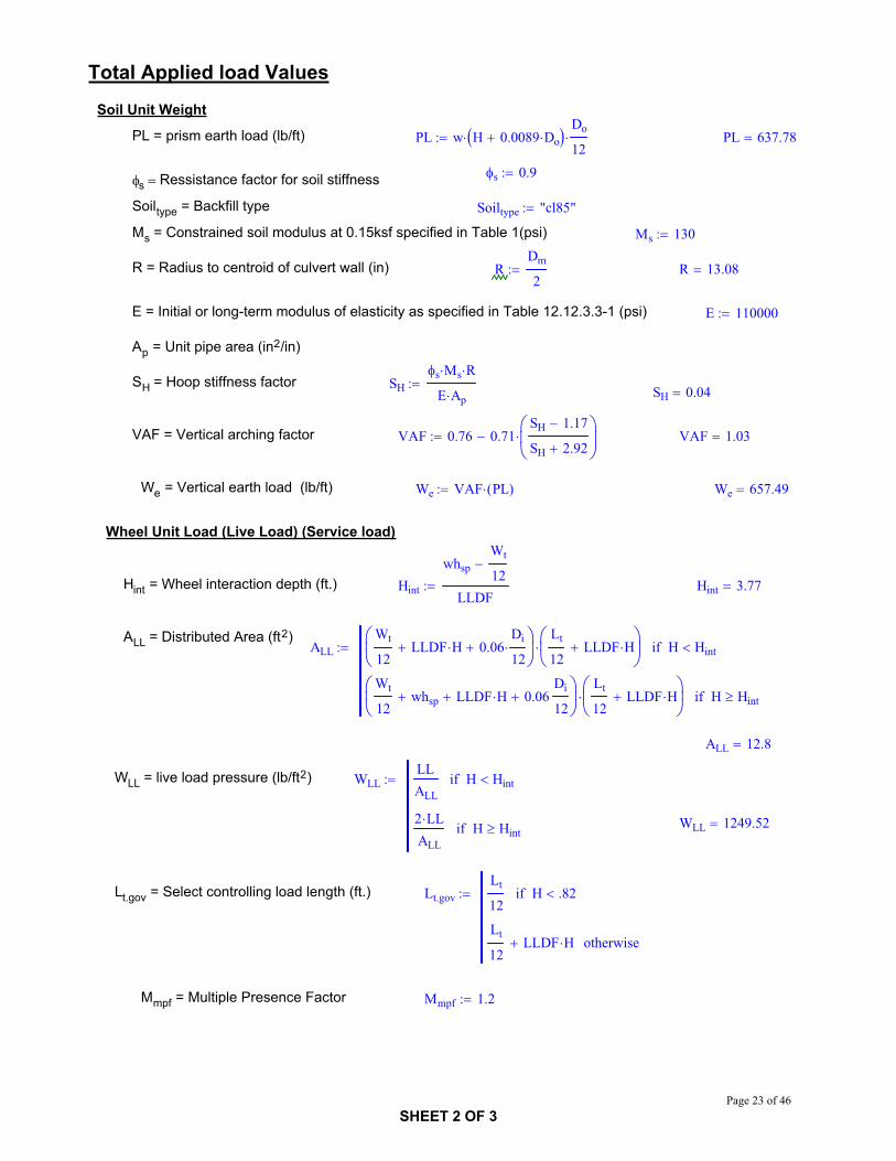
Total Applied load Values
Soil Unit Weight
PL = prism earth load (lb/ft) PL w H 0.0089 DoDo
12PL 637.78
s 0.9s Ressistance factor for soil stiffness
Soiltype = Backfill type Soiltype "cl85"
Ms = Constrained soil modulus at 0.15ksf specified in Table 1(psi) Ms 130
R = Radius to centroid of culvert wall (in) RDm
2R 13.08
E = Initial or long-term modulus of elasticity as specified in Table 12.12.3.3-1 (psi) E 110000
Ap = Unit pipe area (in2/in)
SH = Hoop stiffness factor SHs Ms R
E Ap SH 0.04
VAF = Vertical arching factor VAF 0.76 0.71SH 1.17
SH 2.92VAF 1.03
We = Vertical earth load (lb/ft) We VAF PL( ) We 657.49
Wheel Unit Load (Live Load) (Service load)
Hint = Wheel interaction depth (ft.) Hint
whspWt
12LLDF
Hint 3.77
ALL = Distributed Area (ft2)ALL
Wt
12LLDF H 0.06
Di
12
Lt
12LLDF H H Hintif
Wt
12whsp LLDF H 0.06
Di
12
Lt
12LLDF H H Hintif
ALL 12.8
WLL = live load pressure (lb/ft2) WLLLLALL
H Hintif
2 LLALL
H Hintif WLL 1249.52
Lt.gov = Select controlling load length (ft.) Lt.govLt
12H .82if
Lt
12LLDF H otherwise
Mmpf = Multiple Presence Factor Mmpf 1.2
SHEET 2 OF 3Page 23 of 46
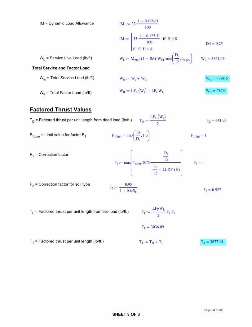
IM = Dynamic Load Allowance IM1 331 0.125 H
100
IM 331 0.125 H
100H 8if
0 H 8ifIM 0.25
WL = Service Live Load (lb/ft) WL Mmpf 1 IM( ) WLL minDi
12Lt.gov WL 3741.07
Total Service and Factor Load
Wts = Total Service Load (lb/ft) Wts We WL Wts 4398.6
Wtf LFd We LFl WL Wtf 7829Wtf = Total Factor Load (lb/ft)
Factored Thrust Values
TD = Factored thrust per unit length from dead load (lb/ft.) TDLFd We
2TD 641.05
F1.Lim = Limit value for factor F1 F1.lim max15Di
1.0 F1.lim 1
F1 = Correction factor
F1 max F1.lim 0.75
Di
12
Lt
12LLDF H( )
F1 1
F2 = Correction factor for soil typeF2
0.951 0.6 SH F2 0.927
TL = Factored thrust per unit length from live load (lb/ft.) TLLFl WL
2F1 F2
TL 3036.09
TT = Factored thrust per unit length (lb/ft.) TT TD TL TT 3677.14
SHEET 3 OF 3Page 24 of 46
CONSULTING ENGINEERS2800 UNIVERSITY AVE SEMINNEAPOLIS, MN 55414
CNAPhone: (612) 379-8805
Fax: (612) 379-8160
CLIENT PROJECT: NCHRP
CALCULATION BY: GL DATE: 9/17/2007
APPROVED BY: CRN DATE: 9/17/2007
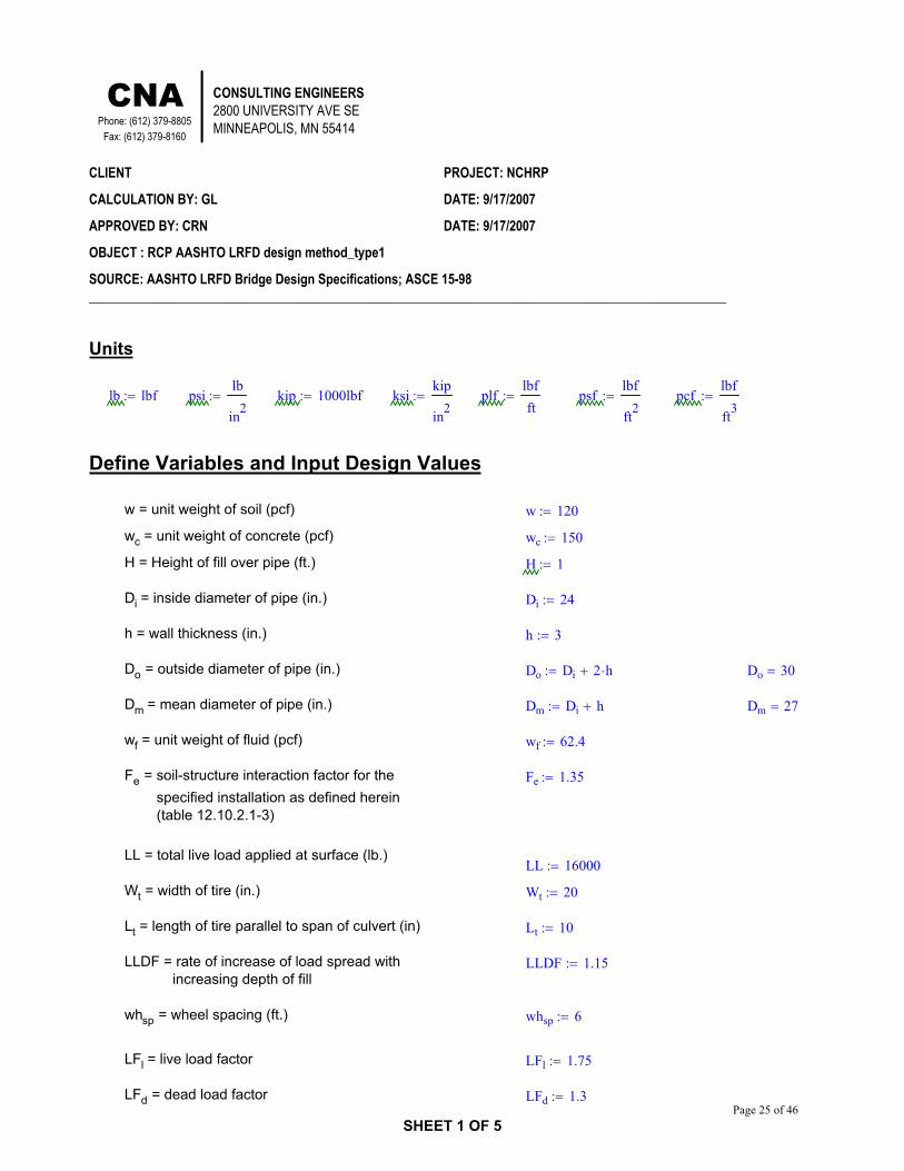
OBJECT : RCP AASHTO LRFD design method_type1
SOURCE: AASHTO LRFD Bridge Design Specifications; ASCE 15-98_________________________________________________________________________________________________
Units
lb lbf psilb
in2kip 1000lbf ksi
kip
in2plf
lbfft
psflbf
ft2pcf
lbf
ft3
Define Variables and Input Design Values
w = unit weight of soil (pcf) w 120
wc = unit weight of concrete (pcf) wc 150
H = Height of fill over pipe (ft.) H 1
Di = inside diameter of pipe (in.) Di 24
h = wall thickness (in.) h 3
Do = outside diameter of pipe (in.) Do Di 2 h Do 30
Dm = mean diameter of pipe (in.) Dm Di h Dm 27
wf = unit weight of fluid (pcf) wf 62.4
Fe = soil-structure interaction factor for the specified installation as defined herein (table 12.10.2.1-3)
Fe 1.35
LL = total live load applied at surface (lb.)LL 16000
Wt = width of tire (in.) Wt 20
Lt = length of tire parallel to span of culvert (in) Lt 10
LLDF = rate of increase of load spread with increasing depth of fill
LLDF 1.15
whsp = wheel spacing (ft.) whsp 6
LFl = live load factor LFl 1.75
LFd = dead load factor LFd 1.3
SHEET 1 OF 5Page 25 of 46

Total Applied load Values
Pipe Unit Weight
A = area of the pipe (in2) A14
Do2 Di
2 A 254.47
Wp = pipe unit weight (lb/ft) Wp wcA
144Wp 265
Soil Unit Weight
PL = prism earth load (lb/ft) PL w H 0.0089 DoDo
12PL 380.1
We = vertical earth load (lb/ft) We Fe PL We 513.13
Fluid Unit Weight
Wf = fluid load (lb/ft) Wf wf14
Di
12
2
Wf 196.04
Wheel Unit Load (Live Load) (Service load)
Hint = Wheel interaction depth (ft.) Hint
whspWt
12LLDF
Hint 3.77
ALL = Distributed Area (ft2)ALL
Wt
12LLDF H
Lt
12LLDF H H Hintif
Wt
12whsp LLDF H
Lt
12LLDF H H Hintif
ALL 5.59
WLL = live load pressure (lb/ft2) WLLLLALL
H Hintif
2 LLALL
H Hintif WLL 2864.1
Lt.gov = Select controlling load length (ft.) Lt.govLt
12H .82if
Lt
12LLDF H otherwise
Mmpf = Multiple Presence Factor Mmpf 1.2
IM = Dynamic Load Allowance IM1 331 0.125 H
100
IM 331 0.125 H
100H 8if
0 H 8ifIM 0.29
WL = Service Live Load (lb/ft) WL Mmpf 1 IM( ) WLL minDi
12Lt.gov WL 8784.85
SHEET 2 OF 5Page 26 of 46

Total Service and Factor Load
Wts = Total Service Load (lb/ft) Wts Wp We Wf WL Wts 9759.1
Wtf LFd Wp We Wf LFl WL Wtf 16640Wtf = Total Factor Load (lb/ft)
Total Moment and Thrust and Shear Values AASHTO LRFDDi 24
Nondimensional Coefficients (Cmi, Cni,Cvi) H 1Installation Type 1 Coefficients; See Table C-3.1. InvertInstallation Type 2 Coefficients; See Table C-3.2.
Installation Type 3 Coefficients; See Table C-3.3.
Installation Type 4 Coefficients; See Table C-3.4.
Cmip 0.225 Cnip 0.077 Cvip 0.437
Cmie 0.091 Cnie 0.188 Cvie 0.143
Cmif 0.088 Cnif 0.445 Cvif 0.141
Cmil 0.165 Cnil 0.046 Cvil 0.15
Moment and Thrust and Shear Values
Factor Values
Mi LFd Cmip Wp Cmie We Cmif Wf LFl Cmil WLDm
2Mi 36413.41
Ni LFd Cnip Wp Cnie We Cnif Wf LFl Cnil WL Ni 668.64
Vi LFd Cvip Wp Cvie We Cvif Wf LFl Cvil WL Vi 2587.94
Service Values
Ms Cmip Wp Cmie We Cmif Wf Cmil WLDm
2Ms 21236.69
Ns Cnip Wp Cnie We Cnif Wf Cnil WL Ns 374.46
Vs Cvip Wp Cvie We Cvif Wf Cvil WL Vs 1534.58
Flexural Resistance at the Strength Limit State
Circumferential Reinforcement
As = Area of reinforcement per length of pipe (in2/ft)
fy = Specified yield strength of reinforcing (ksi) fy 65
d = Distance from compression face to centroid of tension reinforcement (in.) d h 1.5 d 1.5
Mu = Moment due to factored loads (kip-in/ft) MuMi
1000Mu 36.413
Nu = Thrust due to factored load, taken to be positive for compression (kip/ft)
NuNi
1000Nu 0.669
= Resistance factor for flexure specified in Article 12.5.5 ( =0.9, Type 1 installation; =1.0, Other type installations)
0.9
b = Length of reinforcement for flexural resistance provided (in) b 12SHEET 3 OF 5
Page 27 of 46

fc = Compressive strength of concrete (ksi) fc 4
g 0.85 b fc g 40.8
Asg d Nu g g d
2Nu 2 d h 2 Mu
fy As 0.744
Table 12.10.2.1-3
1 2 3 4VAF 1.35 1.4 1.4 1.45HAF 0.45 0.4 0.37 0.3
Installation Type
* Fe shall be taken as the vertical arching factor, VAF
Type Reinforcement C11 Smooth wire or plain bars 12 Welded smooth wire fabric
with 8.0 inch maximumspacing of longitudinals
3 Welded deformed wire fabric,deformed wire, bars, or anyreinforcement with stirrupsanchored thereto
1.5
1.9
Table 1
SHEET 4 OF 5Page 28 of 46

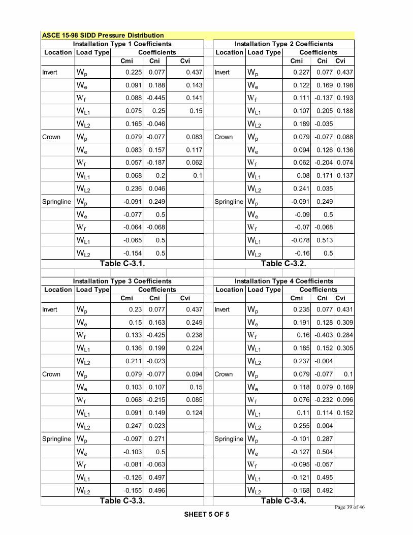
ASCE 15-98 SIDD Pressure Distribution
Location Load Type Location Load TypeCmi Cni Cvi Cmi Cni Cvi
Invert Wp 0.225 0.077 0.437 Invert Wp 0.227 0.077 0.437
We 0.091 0.188 0.143 We 0.122 0.169 0.198
Wf 0.088 -0.445 0.141 Wf 0.111 -0.137 0.193
WL1 0.075 0.25 0.15 WL1 0.107 0.205 0.188
WL2 0.165 -0.046 WL2 0.189 -0.035
Crown Wp 0.079 -0.077 0.083 Crown Wp 0.079 -0.077 0.088
We 0.083 0.157 0.117 We 0.094 0.126 0.136
Wf 0.057 -0.187 0.062 Wf 0.062 -0.204 0.074
WL1 0.068 0.2 0.1 WL1 0.08 0.171 0.137
WL2 0.236 0.046 WL2 0.241 0.035
Springline Wp -0.091 0.249 Springline Wp -0.091 0.249
We -0.077 0.5 We -0.09 0.5
Wf -0.064 -0.068 Wf -0.07 -0.068
WL1 -0.065 0.5 WL1 -0.078 0.513
WL2 -0.154 0.5 WL2 -0.16 0.5
Location Load Type Location Load TypeCmi Cni Cvi Cmi Cni Cvi
Invert Wp 0.23 0.077 0.437 Invert Wp 0.235 0.077 0.431
We 0.15 0.163 0.249 We 0.191 0.128 0.309
Wf 0.133 -0.425 0.238 Wf 0.16 -0.403 0.284
WL1 0.136 0.199 0.224 WL1 0.185 0.152 0.305
WL2 0.211 -0.023 WL2 0.237 -0.004
Crown Wp 0.079 -0.077 0.094 Crown Wp 0.079 -0.077 0.1
We 0.103 0.107 0.15 We 0.118 0.079 0.169
Wf 0.068 -0.215 0.085 Wf 0.076 -0.232 0.096
WL1 0.091 0.149 0.124 WL1 0.11 0.114 0.152
WL2 0.247 0.023 WL2 0.255 0.004
Springline Wp -0.097 0.271 Springline Wp -0.101 0.287
We -0.103 0.5 We -0.127 0.504
Wf -0.081 -0.063 Wf -0.095 -0.057
WL1 -0.126 0.497 WL1 -0.121 0.495
WL2 -0.155 0.496 WL2 -0.168 0.492
Coefficients CoefficientsInstallation Type 1 Coefficients Installation Type 2 Coefficients
Installation Type 3 Coefficients Installation Type 4 CoefficientsCoefficients Coefficients
Table C-3.1. Table C-3.2.
Table C-3.3. Table C-3.4.SHEET 5 OF 5
Page 29 of 46

CONSULTING ENGINEERS2800 UNIVERSITY AVE SEMINNEAPOLIS, MN 55414
CNAPhone: (612) 379-8805
Fax: (612) 379-8160
CLIENT PROJECT: NCHRP
CALCULATION BY: GL DATE: 9/18/2007
APPROVED BY: CRN DATE: 9/18/2007
OBJECT : RCP AASHTO Standard design method_type1
SOURCE: AASHTO standard Bridge Design Specifications; ASCE 15-98_________________________________________________________________________________________________
Units
lb lbf psilb
in2kip 1000lbf ksi
kip
in2plf
lbfft
psflbf
ft2pcf
lbf
ft3
Define Variables and Input Design Values
w = unit weight of soil (pcf) w 120
wc = unit weight of concrete (pcf) wc 150
H = Height of fill over pipe (ft.) H 1
Di = inside diameter of pipe (in.) Di 96
h = wall thickness (in.) h 9
Do = outside diameter of pipe (in.) Do Di 2 h Do 114
Dm = mean diameter of pipe (in.) Dm Di h Dm 105
wf = unit weight of fluid (pcf) wf 62.4
Fe = soil-structure interaction factor for the specified installation as defined herein (table 12.10.2.1-3)
Fe 1.35
LL = total live load applied at surface (lb.)LL 16000
Wt = width of tire (in.) Wt 20
Lt = length of tire parallel to span of culvert (in) Lt 10
LLDF = rate of increase of load spread with increasing depth of fill
LLDF 1.75
whsp = wheel spacing (ft.) whsp 6
LFl = live load factor LFl 2.17
LFd = dead load factor LFd 1.3
SHEET 1 OF 5Page 30 of 46

Total Applied load Values
Pipe Unit Weight
A = area of the pipe (in2) A14
Do2 Di
2 A 2968.81
Wp = pipe unit weight (lb/ft) Wp wcA
144Wp 3093
Soil Unit Weight
PL = prism earth load (lb/ft) PL w H 0.0089 DoDo
12PL 2296.64
We = vertical earth load (lb/ft) We Fe PL We 3100.47
Fluid Unit Weight
Wf = fluid load (lb/ft) Wf wf14
Di
12
2
Wf 3136.57
Wheel Unit Load (Live Load) (Service load)
Hint = Wheel interaction depth (ft.) Hintwhsp
LLDFHint 3.43
ALL LLDF H( ) LLDF H( ) H Hintif
whsp LLDF H LLDF H( ) H HintifALL = Distributed Area (ft2) ALL 3.06
WLL = live load pressure (lb/ft2) WLLLLALL
H Hintif
2 LLALL
H Hintif WLL 5224.49
I = Impact fraction I 0.3 0 H 1if
0.2 1 H 2if
0.1 2 H 3if
0 H 3if
I 0.3
WL = Service Live Load (lb/ft) WL 1 I( ) WLL minDi
12LLDF H WL 11885.71
SHEET 2 OF 5Page 31 of 46

Total Service and Factor Load
Wts = Total Service Load (lb/ft) Wts Wp We Wf WL Wts 21215.3
Wtf LFd Wp We Wf LFl WL Wtf 37920.4Wtf = Total Factor Load (lb/ft)
Total Moment and Thrust and Shear Values AASHTO Standard
Di 96Nondimensional Coefficients (Cmi, Cni,Cvi) H 1
Installation Type 1 Coefficients; See Table C-3.1. CrownInstallation Type 2 Coefficients; See Table C-3.2.
Installation Type 3 Coefficients; See Table C-3.3.
Installation Type 4 Coefficients; See Table C-3.4.
Cmip 0.079 Cnip 0.077 Cvip 0.083
Cmie 0.083 Cnie 0.157 Cvie 0.117
Cmif 0.057 Cnif 0.187 Cvif 0.062
Cmil 0.236 Cnil 0.046 Cvil 0.1
Moment and Thrust and Shear Values
Factor Values
Mi LFd Cmip Wp Cmie We Cmif Wf LFl Cmil WLDm
2Mi 3.66 105
Ni LFd Cnip Wp Cnie We Cnif Wf LFl Cnil WL Ni 747.18
Vi LFd Cvip Wp Cvie We Cvif Wf LFl Cvil WL Vi 3637.27
Service Values
Ms Cmip Wp Cmie We Cmif Wf Cmil WLDm
2Ms 1.83 105
Ns Cnip Wp Cnie We Cnif Wf Cnil WL Ns 208.86
Vs Cvip Wp Cvie We Cvif Wf Cvil WL Vs 2002.47
Flexural Resistance at the Strength Limit State
Circumferential Reinforcement
As = Area of reinforcement per length of pipe (in2/ft)
fy = Specified yield strength of reinforcing (ksi) fy 65
d = Distance from compression face to centroid of tension reinforcement (in.) d h 1.5 d 7.5
Mu = Moment due to factored loads (kip-in/ft) MuMi
1000Mu 366.002
Nu = Thrust due to factored load, taken to be positive for compression (kip/ft)
NuNi
1000Nu 0.747
SHEET 3 OF 5Page 32 of 46
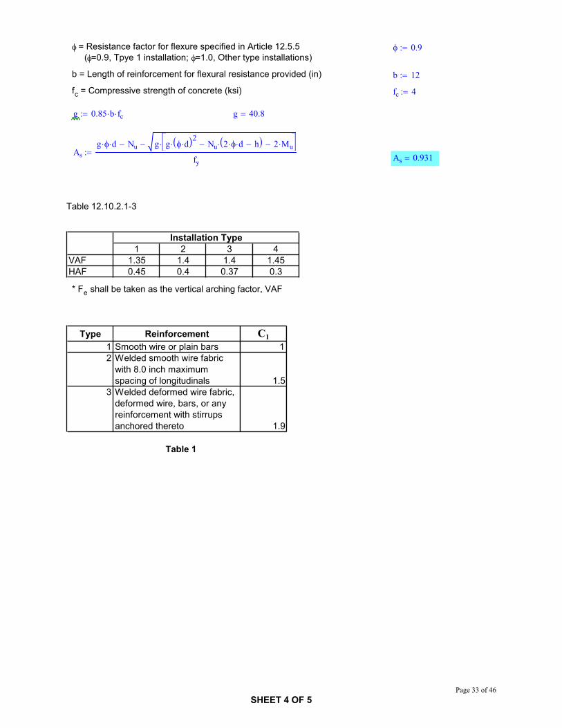
= Resistance factor for flexure specified in Article 12.5.5 ( =0.9, Tpye 1 installation; =1.0, Other type installations)
0.9
b = Length of reinforcement for flexural resistance provided (in) b 12
fc = Compressive strength of concrete (ksi) fc 4
g 0.85 b fc g 40.8
Asg d Nu g g d
2Nu 2 d h 2 Mu
fy As 0.931
Table 12.10.2.1-3
1 2 3 4VAF 1.35 1.4 1.4 1.45HAF 0.45 0.4 0.37 0.3
Installation Type
* Fe shall be taken as the vertical arching factor, VAF
Type Reinforcement C11 Smooth wire or plain bars 12 Welded smooth wire fabric
with 8.0 inch maximumspacing of longitudinals
3 Welded deformed wire fabric,deformed wire, bars, or anyreinforcement with stirrupsanchored thereto
1.5
1.9
Table 1
SHEET 4 OF 5Page 33 of 46

ASCE 15-98 SIDD Pressure Distribution
Location Load Type Location Load TypeCmi Cni Cvi Cmi Cni Cvi
Invert Wp 0.225 0.077 0.437 Invert Wp 0.227 0.077 0.437
We 0.091 0.188 0.143 We 0.122 0.169 0.198
Wf 0.088 -0.445 0.141 Wf 0.111 -0.137 0.193
WL1 0.075 0.25 0.15 WL1 0.107 0.205 0.188
WL2 0.165 -0.046 WL2 0.189 -0.035
Crown Wp 0.079 -0.077 0.083 Crown Wp 0.079 -0.077 0.088
We 0.083 0.157 0.117 We 0.094 0.126 0.136
Wf 0.057 -0.187 0.062 Wf 0.062 -0.204 0.074
WL1 0.068 0.2 0.1 WL1 0.08 0.171 0.137
WL2 0.236 0.046 WL2 0.241 0.035
Springline Wp -0.091 0.249 Springline Wp -0.091 0.249
We -0.077 0.5 We -0.09 0.5
Wf -0.064 -0.068 Wf -0.07 -0.068
WL1 -0.065 0.5 WL1 -0.078 0.513
WL2 -0.154 0.5 WL2 -0.16 0.5
Location Load Type Location Load TypeCmi Cni Cvi Cmi Cni Cvi
Invert Wp 0.23 0.077 0.437 Invert Wp 0.235 0.077 0.431
We 0.15 0.163 0.249 We 0.191 0.128 0.309
Wf 0.133 -0.425 0.238 Wf 0.16 -0.403 0.284
WL1 0.136 0.199 0.224 WL1 0.185 0.152 0.305
WL2 0.211 -0.023 WL2 0.237 -0.004
Crown Wp 0.079 -0.077 0.094 Crown Wp 0.079 -0.077 0.1
We 0.103 0.107 0.15 We 0.118 0.079 0.169
Wf 0.068 -0.215 0.085 Wf 0.076 -0.232 0.096
WL1 0.091 0.149 0.124 WL1 0.11 0.114 0.152
WL2 0.247 0.023 WL2 0.255 0.004
Springline Wp -0.097 0.271 Springline Wp -0.101 0.287
We -0.103 0.5 We -0.127 0.504
Wf -0.081 -0.063 Wf -0.095 -0.057
WL1 -0.126 0.497 WL1 -0.121 0.495
WL2 -0.155 0.496 WL2 -0.168 0.492
Coefficients CoefficientsInstallation Type 1 Coefficients Installation Type 2 Coefficients
Installation Type 3 Coefficients Installation Type 4 CoefficientsCoefficients Coefficients
Table C-3.1. Table C-3.2.
Table C-3.3. Table C-3.4.SHEET 5 OF 5
Page 34 of 46

CONSULTING ENGINEERS2800 UNIVERSITY AVE SEMINNEAPOLIS, MN 55414
CNAPhone: (612) 379-8805
Fax: (612) 379-8160
CLIENT PROJECT: NCHRP
CALCULATION BY: GL DATE: 9/18/2007
APPROVED BY: CRN DATE: 9/18/2007
OBJECT : RCP Proposed Simplified Equation method_type1
SOURCE: NCHRP 15-29; ASCE 15-98_________________________________________________________________________________________________
Units
lb lbf psilb
in2kip 1000lbf ksi
kip
in2plf
lbfft
psflbf
ft2pcf
lbf
ft3
Define Variables and Input Design Values
w = unit weight of soil (pcf) w 120
wc = unit weight of concrete (pcf) wc 150
H = Height of fill over pipe (ft.) H 1
Di = inside diameter of pipe (in.) Di 96
h = wall thickness (in.) h 9
Do = outside diameter of pipe (in.) Do Di 2 h Do 114
Dm = mean diameter of pipe (in.) Dm Di h Dm 105
wf = unit weight of fluid (pcf) wf 62.4
Fe = soil-structure interaction factor for the specified installation as defined herein (table 12.10.2.1-3)
Fe 1.35
LL = total live load applied at surface (lb.)LL 16000
Wt = width of tire (in.) Wt 20
Lt = length of tire parallel to span of culvert (in) Lt 10
LLDF = rate of increase of load spread with increasing depth of fill
LLDF 1.15
whsp = wheel spacing (ft.) whsp 6
LFl = live load factor LFl 1.75
LFd = dead load factor LFd 1.3
SHEET 1 OF 5Page 35 of 46

Total Applied load Values
Pipe Unit Weight
A = area of the pipe (in2) A14
Do2 Di
2 A 2968.81
Wp = pipe unit weight (lb/ft) Wp wcA
144Wp 3093
Soil Unit Weight
PL = prism earth load (lb/ft) PL w H 0.0089 DoDo
12PL 2296.64
We = vertical earth load (lb/ft) We Fe PL We 3100.47
Fluid Unit Weight
Wf = fluid load (lb/ft) Wf wf14
Di
12
2
Wf 3136.57
Wheel Unit Load (Live Load) (Service load)
Di = Inside diameter of concrete pipe (in)
LLDFcp = Live load distribution factor for concrete pipe
LLDF 1.15 Di 24if
0.00833 Di 0.95 24 Di 96if
1.75 Di 96ifLLDF 1.75
Hint = Wheel interaction depth (ft.) Hint
whspWt
12
.06 Di
12LLDF
Hint 2.2
ALL = Distributed Area (ft2)ALL
Wt
12LLDF H 0.06
Di
12
Lt
12LLDF H H Hintif
Wt
12whsp LLDF H 0.06
Di
12
Lt
12LLDF H H Hintif
ALL 10.07
WLL = live load pressure (lb/ft2) WLLLLALL
H Hintif
2 LLALL
H Hintif WLL 1589.45
Lt.gov = Select controlling load length (ft.) Lt.govLt
12H .82if
Lt
12LLDF H otherwise
Mmpf = Multiple Presence Factor Mmpf 1.2
SHEET 2 OF 5Page 36 of 46

IM = Dynamic Load Allowance IM1 331 0.125 H
100
IM 331 0.125 H
100H 8if
0 H 8ifIM 0.29
WL = Service Live Load (lb/ft) WL Mmpf 1 IM( ) WLL minDi
12Lt.gov WL 6350.04
Total Service and Factor Load
Wts = Total Service Load (lb/ft) Wts Wp We Wf WL Wts 15679.6
Wtf LFd Wp We Wf LFl WL Wtf 23241Wtf = Total Factor Load (lb/ft)
Total Moment and Thrust and Shear Values H 1
Di 96Nondimensional Coefficients (Cmi, Cni,Cvi)
Installation Type 1 Coefficients; See Table C-3.1.
Installation Type 2 Coefficients; See Table C-3.2.
Installation Type 3 Coefficients; See Table C-3.3.
Installation Type 4 Coefficients; See Table C-3.4.
Cmip 0.079 Cnip 0.077 Cvip 0.083
Cmie 0.083 Cnie 0.157 Cvie 0.117
Cmif 0.057 Cnif 0.187 Cvif 0.062
Cmil 0.236 Cnil 0.046 Cvil 0.1
Moment and Thrust and Shear Values
Factor Values
Mi LFd Cmip Wp Cmie We Cmif Wf LFl Cmil WLDm
2Mi 1.84 105
Ni LFd Cnip Wp Cnie We Cnif Wf LFl Cnil WL Ni 71.93
Vi LFd Cvip Wp Cvie We Cvif Wf LFl Cvil WL Vi 2169.33
Service Values
Ms Cmip Wp Cmie We Cmif Wf Cmil WLDm
2Ms 1.14 105
Ns Cnip Wp Cnie We Cnif Wf Cnil WL Ns 45.79
Vs Cvip Wp Cvie We Cvif Wf Cvil WL Vs 1448.9
Flexural Resistance at the Strength Limit State
Circumferential Reinforcement
As = Area of reinforcement per length of pipe (in2/ft)
fy = Specified yield strength of reinforcing (ksi) fy 65
SHEET 3 OF 5Page 37 of 46

d = Distance from compression face to centroid of tension reinforcement (in.) d h 1.5 d 7.5
Mu = Moment due to factored loads (kip-in/ft) MuMi
1000Mu 184.124
Nu = Thrust due to factored load, taken to be positive for compression (kip/ft)
NuNi
1000Nu 0.072
= Resistance factor for flexure specified in Article 12.5.5 ( =0.9, Tpye 1 installation; =1.0, Other type installations)
0.9
b = Length of reinforcement for flexural resistance provided (in) b 12
fc = Compressive strength of concrete (ksi) fc 4
g 0.85 b fc g 40.8
Asg d Nu g g d
2Nu 2 d h 2 Mu
fy As 0.442
Table 12.10.2.1-3
1 2 3 4VAF 1.35 1.4 1.4 1.45HAF 0.45 0.4 0.37 0.3
Installation Type
* Fe shall be taken as the vertical arching factor, VAF
Type Reinforcement C11 Smooth wire or plain bars 12 Welded smooth wire fabric
with 8.0 inch maximumspacing of longitudinals
3 Welded deformed wire fabric,deformed wire, bars, or anyreinforcement with stirrupsanchored thereto
1.5
1.9
Table 1
SHEET 4 OF 5Page 38 of 46
ASCE 15-98 SIDD Pressure Distribution
Location Load Type Location Load TypeCmi Cni Cvi Cmi Cni Cvi
Invert Wp 0.225 0.077 0.437 Invert Wp 0.227 0.077 0.437
We 0.091 0.188 0.143 We 0.122 0.169 0.198
Wf 0.088 -0.445 0.141 Wf 0.111 -0.137 0.193
WL1 0.075 0.25 0.15 WL1 0.107 0.205 0.188
WL2 0.165 -0.046 WL2 0.189 -0.035
Crown Wp 0.079 -0.077 0.083 Crown Wp 0.079 -0.077 0.088
We 0.083 0.157 0.117 We 0.094 0.126 0.136
Wf 0.057 -0.187 0.062 Wf 0.062 -0.204 0.074
WL1 0.068 0.2 0.1 WL1 0.08 0.171 0.137
WL2 0.236 0.046 WL2 0.241 0.035
Springline Wp -0.091 0.249 Springline Wp -0.091 0.249
We -0.077 0.5 We -0.09 0.5
Wf -0.064 -0.068 Wf -0.07 -0.068
WL1 -0.065 0.5 WL1 -0.078 0.513
WL2 -0.154 0.5 WL2 -0.16 0.5
Location Load Type Location Load TypeCmi Cni Cvi Cmi Cni Cvi
Invert Wp 0.23 0.077 0.437 Invert Wp 0.235 0.077 0.431
We 0.15 0.163 0.249 We 0.191 0.128 0.309
Wf 0.133 -0.425 0.238 Wf 0.16 -0.403 0.284
WL1 0.136 0.199 0.224 WL1 0.185 0.152 0.305
WL2 0.211 -0.023 WL2 0.237 -0.004
Crown Wp 0.079 -0.077 0.094 Crown Wp 0.079 -0.077 0.1
We 0.103 0.107 0.15 We 0.118 0.079 0.169
Wf 0.068 -0.215 0.085 Wf 0.076 -0.232 0.096
WL1 0.091 0.149 0.124 WL1 0.11 0.114 0.152
WL2 0.247 0.023 WL2 0.255 0.004
Springline Wp -0.097 0.271 Springline Wp -0.101 0.287
We -0.103 0.5 We -0.127 0.504
Wf -0.081 -0.063 Wf -0.095 -0.057
WL1 -0.126 0.497 WL1 -0.121 0.495
WL2 -0.155 0.496 WL2 -0.168 0.492
Coefficients CoefficientsInstallation Type 1 Coefficients Installation Type 2 Coefficients
Installation Type 3 Coefficients Installation Type 4 CoefficientsCoefficients Coefficients
Table C-3.1. Table C-3.2.
Table C-3.3. Table C-3.4.SHEET 5 OF 5
Page 39 of 46

CONSULTING ENGINEERS2800 UNIVERSITY AVE SEMINNEAPOLIS, MN 55414
CNAPhone: (612) 379-8805
Fax: (612) 379-8160
CLIENT PROJECT: NCHRP
CALCULATION BY: GL DATE: 9/12/2007
APPROVED BY: CRN DATE: 9/12/2007
OBJECT : Corrugated Metal Pipe - AASHTO LRFD Design Diameter=8 Depth=1
SOURCE: AASHTO LRFD Bridge Design Specifications; ASCE 15-98_________________________________________________________________________________________________
Units
lb lbf psilb
in2kip 1000lbf ksi
kip
in2plf
lbfft
psflbf
ft2pcf
lbf
ft3
Define Variables and Input Design Values
w = unit weight of soil (pcf) w 120
wc = unit weight of steel (pcf) wc 490
H = Height of fill over pipe (ft.) H 1
Di = inside diameter of pipe (in.) Di 96
h = wall thickness (in.) h 0.109
Do = outside diameter of pipe (in.) Do Di 2 h Do 96.22
Dm = mean diameter of pipe (in.) Dm Di h Dm 96.11
Fe = soil-structure interaction factor for the specified installation as defined herein
Fe 1.0
Ap 0.968AP = unit pipe area (in2/ft.)
LL = total live load applied at surface (lb.) LL 16000
Wt = width of tire (in.) Wt 20
Lt = length of tire parallel to span of culvert (in) Lt 10
LLDF = rate of increase of load spread with increasing depth of fill
LLDF 1.15
whsp 6whsp = wheel spacing (ft.)
LFl 1.75LFl = live load factor
LFd = dead load factor LFd 1.95
SHEET 1 OF 2Page 40 of 46

Total Applied load Values
Soil Unit Weight
PL = prism earth load (lb/ft) PL w H 0.0089 DoDo
12PL 1786.13
We = vertical earth load (lb/ft) We Fe PL We 1786.13
Wheel Unit Load (Live Load) (Service load)
Hint = Wheel interaction depth (ft.) Hint
whspWt
12LLDF
Hint 3.77
ALL = Distributed Area (ft2)ALL
Wt
12LLDF H
Lt
12LLDF H H Hintif
Wt
12whsp LLDF H
Lt
12LLDF H H Hintif
ALL 5.59
WLL = live load pressure (lb/ft2) WLLLLALL
H Hintif
2 LLALL
H Hintif WLL 2864.1
Lt.gov = Select controlling load length (ft.) Lt.govLt
12H .82if
Lt
12LLDF H otherwise
Mmpf = Multiple Presence Factor Mmpf 1.2
IM = Dynamic Load Allowance IM1 331 0.125 H
100
IM 331 0.125 H
100H 8if
0 H 8ifIM 0.29
WL = Service Live Load (lb/ft) WL Mmpf 1 IM( ) WLL minDm
12Lt.gov WL 8784.85
Total Service and Factor Load
Wts = Total Service Load (lb/ft) Wts We WL Wts 10571
Wtf = Total Factor Load (lb/ft) Wtf LFd We LFl WL Wtf 18856.5
Factored Thrust ValuesTL
Wtf
2TL = Factored thrust per unit length (lb/ft.) TL 9428.23
SHEET 2 OF 2Page 41 of 46

CONSULTING ENGINEERS2800 UNIVERSITY AVE SEMINNEAPOLIS, MN 55414
CNAPhone: (612) 379-8805
Fax: (612) 379-8160
CLIENT PROJECT: NCHRP
CALCULATION BY: GL DATE: 9/12/2007
APPROVED BY: CRN DATE: 9/12/2007
OBJECT : Corrugated Metal Pipe - AASHTO Standard Design Diameter= 8 Depth=1
SOURCE: AASHTO standard Bridge Design Specifications; ASCE 15-98_________________________________________________________________________________________________
Units
lb lbf psilb
in2kip 1000lbf ksi
kip
in2plf
lbfft
psflbf
ft2pcf
lbf
ft3
Define Variables and Input Design Values
w = unit weight of soil (pcf) w 120
ws = unit weight of concrete (pcf) ws 490
H = Height of fill over pipe (ft.) H 1
Di = inside diameter of pipe (in.) Di 96
h = wall thickness (in.) h 0.109
Do = outside diameter of pipe (in.) Do Di 2 h Do 96.22
Dm = mean diameter of pipe (in.) Dm Di h Dm 96.11
Fe = soil-structure interaction factor for the specified installation as defined herein
Fe 1.0
AP = unit pipe area (in2/ft.) Ap 0.968
LL = total live load applied at surface (lb.) LL 16000
Wt = width of tire (in.) Wt 20
Lt = length of tire parallel to span of culvert (in) Lt 10
LLDF = rate of increase of load spread with increasing depth of fill
LLDF 1.75
whsp 6whsp = wheel spacing (ft.)
LFl 2.17LFl = live load factor
LFd 1.95LFd = dead load factor
SHEET 1 OF 2Page 42 of 46
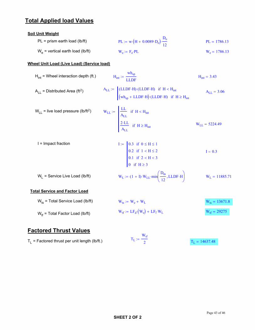
Total Applied load Values
Soil Unit Weight
PL = prism earth load (lb/ft) PL w H 0.0089 DoDo
12PL 1786.13
We = vertical earth load (lb/ft) We Fe PL We 1786.13
Wheel Unit Load (Live Load) (Service load)
Hint = Wheel interaction depth (ft.) Hintwhsp
LLDFHint 3.43
ALL LLDF H( ) LLDF H( ) H Hintif
whsp LLDF H LLDF H( ) H HintifALL = Distributed Area (ft2) ALL 3.06
WLL = live load pressure (lb/ft2) WLLLLALL
H Hintif
2 LLALL
H Hintif WLL 5224.49
I = Impact fraction I 0.3 0 H 1if
0.2 1 H 2if
0.1 2 H 3if
0 H 3if
I 0.3
WL = Service Live Load (lb/ft) WL 1 I( ) WLL minDm
12LLDF H WL 11885.71
Total Service and Factor Load
Wts = Total Service Load (lb/ft) Wts We WL Wts 13671.8
Wtf LFd We LFl WL Wtf 29275Wtf = Total Factor Load (lb/ft)
Factored Thrust ValuesTL
Wtf
2TL = Factored thrust per unit length (lb/ft.) TL 14637.48
SHEET 2 OF 2Page 43 of 46

CONSULTING ENGINEERS2800 UNIVERSITY AVE SEMINNEAPOLIS, MN 55414
CNAPhone: (612) 379-8805
Fax: (612) 379-8160
CLIENT PROJECT: NCHRP
CALCULATION BY: GL DATE: 9/12/2007
APPROVED BY: CRN DATE: 9/12/2007
OBJECT : Corrugated Metal Pipe - Simplified Design Equation
SOURCE: NCHRP 15-29; ASCE 15-98_________________________________________________________________________________________________
Units
lb lbf psilb
in2kip 1000lbf ksi
kip
in2plf
lbfft
psflbf
ft2pcf
lbf
ft3
Define Variables and Input Design Values
w = unit weight of soil (pcf) w 120
wc = unit weight of steel (pcf) wc 490
H = Height of fill over pipe (ft.) H 2
Di = inside diameter of pipe (in.) Di 24
h = wall thickness (in.) h 0.079
Do = outside diameter of pipe (in.) Do Di 2 h Do 24.16
Dm = mean diameter of pipe (in.) Dm Di h Dm 24.08
Fe = soil-structure interaction factor for the specified installation as defined herein
Fe 1.0
AP = unit pipe area (in2/ft.) Ap 0.968
LL = total live load applied at surface (lb.)LL 16000
Wt = width of tire (in.) Wt 20
Lt = length of tire parallel to span of culvert (in) Lt 10
LLDF = rate of increase of load spread with increasing depth of fill
LLDF 1.15
whsp 6whsp = wheel spacing (ft.)
LFl 1.75LFl = live load factor
LFd 1.95LFd = dead load factor
SHEET 1 OF 3Page 44 of 46

Total Applied load Values
Soil Unit Weight
PL = prism earth load (lb/ft) PL w H 0.0089 DoDo
12PL 535.1
We = vertical earth load (lb/ft) We Fe PL We 535.1
Wheel Unit Load (Live Load) (Service load)
Hint = Wheel interaction depth (ft.) Hint
whspWt
12LLDF
Hint 3.77
ALL = Distributed Area (ft2)ALL
Wt
12LLDF H 0.06
Di
12
Lt
12LLDF H H Hintif
Wt
12whsp LLDF H 0.06
Di
12
Lt
12LLDF H H Hintif
ALL 12.8
WLL = live load pressure (lb/ft2) WLLLLALL
H Hintif
2 LLALL
H Hintif WLL 1249.52
Lt.gov = Select controlling load length (ft.) Lt.govLt
12H .82if
Lt
12LLDF H otherwise
Mmpf = Multiple Presence Factor Mmpf 1.2
IM = Dynamic Load Allowance IM1 331 0.125 H
100
IM 331 0.125 H
100H 8if
0 H 8ifIM 0.25
WL = Service Live Load (lb/ft) WL Mmpf 1 IM( ) WLL minDm
12Lt.gov WL 3753.39
Total Service and Factor Load
Wts = Total Service Load (lb/ft) Wts We WL Wts 4288.5
Wtf LFd We LFl WL Wtf 7611.9Wtf = Total Factor Load (lb/ft)
SHEET 2 OF 3Page 45 of 46
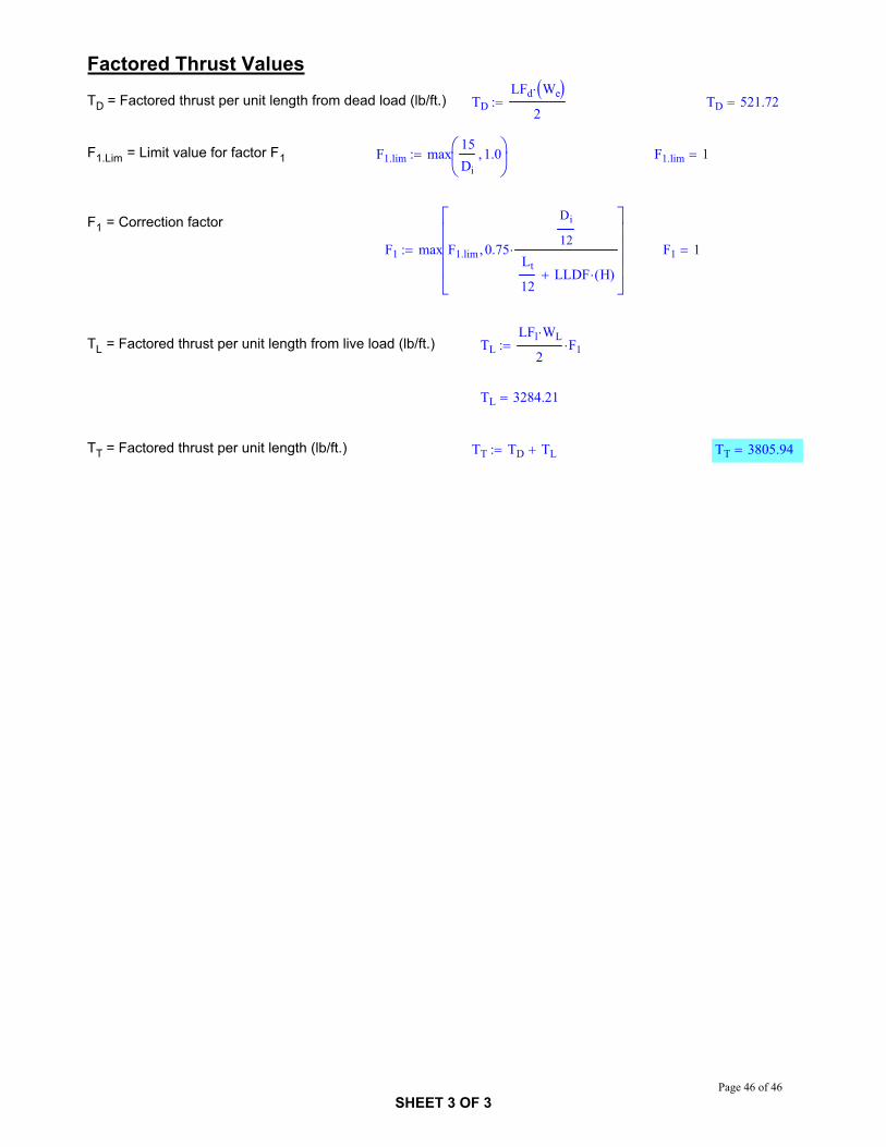
Factored Thrust Values
TD = Factored thrust per unit length from dead load (lb/ft.) TDLFd We
2TD 521.72
F1.Lim = Limit value for factor F1 F1.lim max15Di
1.0 F1.lim 1
F1 = Correction factor
F1 max F1.lim 0.75
Di
12
Lt
12LLDF H( )
F1 1
TL = Factored thrust per unit length from live load (lb/ft.) TLLFl WL
2F1
TL 3284.21
TT = Factored thrust per unit length (lb/ft.) TT TD TL TT 3805.94
SHEET 3 OF 3Page 46 of 46