arvind steel centre.company.catlock
TRANSCRIPT


ARVIND STEEL CENTRE
e 0 the leading firm engaged in Manufacturing &Processing large variety of Butt-Welding I Forged Pipe-Fittings,FlaIiIge5 in Carbon y eel, Stainless Steel, NickeUSuperAIIoJr.>& l~rffihEs ferrous I etaIs.
t:rlt::e.:::::::a:;~~stmdaJtIs and as perspecifications/drawings for
iG:::aries., etrochemicals, Chemicals, Oil & Gas,ceulicals, Food & Beverages, Sugar, Paper,
St.:pburi1diJ19, Aerospace, Engineering, Nuclear, Defence,=e;aa:lm Centers etc.=Wnrrn:;rllrf:lcluring phase, from forging to welding, machining to
out . a vast array of modern equipment and. controlled through out the
SPECTION
Uhde India Ltd.
Email: [email protected].: www.arVindsteelcentre.com
manufacturing phases, thanks to rigorous QA & QC proceduresand external chemical & mechanical laboratories well equipped toperform both destructive & non-destructive examinations.
We provide original Material Test Certificates, GovernmentiLloydsapproved labora Of'{ Tes Certificates, Third Party Inspection('.e{jfu1ai7esandGuam teeiWarranty Certificates for the supplies.(Aur missil:•.•oHs 'to provide the best customer service by supplying
o-date technology, respecting the, moniblring the progress of the work and
saf6fyilgmgernrnqll'in:lI111ents,than s to our large inventory of rawmal:eri.ails, semHinished and finished products.
Our customers are end-users, fabricators and distributors aroundthe world. Our mission is to be always able to represent for ourcustomers a reference for reliability, competence and service. Webuild relationships with our customers, which last and contribute totheir success, because we know that their success is our success.List of third Party Inspection agencies under which we can supplythe materials:-
inspection of any third party. Third party Inspection offers quality and thorough Inspection for buyers. Thenominated by client or we can arrange the third party inspection by various world class reputed agency like
~ (I;1~-
~I.. j,
Nuclear Power Corp. of India Ltd.
GTATAl.loyclsK'eg,sfer
TATA Project
1

Types:Elbow, Tee, Union, Cross, Coup Bushing, Plug, Swage Nipple, Welding Boss, Hexagon Nipple,Barrel Nipple, Welding Nipple, Parraler Nipple, Street Elbow, Hexagon Nut, Hose Nipple, Bend,Adapter, Insert, Weldolet, Elbowlet, Sockolet, Threadolet, Nipolet, Letrolet, etc.
Material Grades:Carbon Steel: ASTM A105 / A694 F42/46/ 52/56/ 60/ 65/70 / A350 LF3/ A350 Lf2.Alloy Steel: ASTM A182 F1/ F5/ F9/ F11/ F22/F91 etc.Stainless Steel: ASTM A182 F304/ 304U 304H/ 316/ 316U 317/ 317U 321/310/347/ 904L etc.Others: Monel, Nickel, Inconel, Hastalloy, Copper, Brass, Bronze, Titanium, Tantalum, Bismuth,Aluminium, High Speed Steel, Zinc, Lead, etc.Size: 1/4- B TO 4- B. (Socketweld & Threaded)
Class: 3000#, 6000#, 9000#.
Main Products:
FLANGESTypes:Weldneck, Slipon, Blind, Socket Weld, Lap Joint, Spectacles, Ring Joint, Orific, LongWeldneck, Deck Flange, etc.
Material Grades:Carbon Steel: ASTM A105/A694/F42/46/ 52/ 56/ 60/ 65/70/A350 LF3/A350 LF2, C22.8, etc.Alloy Steel: ASTM A182 F1/ F5/ F9/ F11/ F22/ F91 etc.Stainless Steel: ASTM A182 F304/304U 304H/ 316/ 316U 317/ 317U 321/ 310/ 347/904Letc.Others: Monel, Nickel, Inconel, Hastalloy, Copper,Brass, Bronze, Titanium, Tantalum,
Bismuth, Aluminium, High Speed Steel, Zinc, Lead, etc.Size:1/2" NB TO 24" NB. (above 24" as per customers requirement)Class:150#, 300#, 400#, 600#, 900#,1500# & 2500#.
FORGED FITTINGS
BUTT WELD FITTINGSTypes:Elbow, Equal/unequal Tee, Concentric/Eccentric Reducers, Caps, Cross, Return Bend, Long
Piggable Bends, 30/50/60/80 upto 220, S/J/U/Expansion Bends & Swivels are manufacturedaccording to ANSI B16.9, B 16.28, MSS SP-43, MSS SP-95 & NACE etc.
Material Grades:Carbon Steel: A234 WPB, WPCAlloy Steel: A234 WP1 , WP5, WP9, WFl11, WP12, WP22, Wp91
Stainless Steel: A403 304/UH, 310/H, 316/UH, 316Ti, 321/H, 347/H, 904LLow Temperature Steel: A420 WPL3, WPL6
High Yield: WPHY42, 52, 60, 65, 70Copper Alloys: Copper, Cupro Nickel, Brass, Gunmetal etc.
eI Alloys: 200, 400, K500, 600, 625, 800, 825- •••••••. J•• ~ •••• 'fS: ALLOY 20, ALLOY C, ALLOY C276, ALLOY B2
- a Super Dupl'e'x:"-A815 UNS31803, UNS31254, UNS S32750 & S32760
- .- 'e -024- B (above 24" NB two half Elbow upto 72"NB).
Email: [email protected].: www.arvindsteelcentre.com
02

ARVIND STEEL CENTRE
PIPES &. TUBES
Email: [email protected].: www.arvindsteelcentre.com
OTHER PRODUCTS
Stainless Steel Seamless & ERW Tubes for Boilers, Super Heaters, HeatExchangers and Condensers: as per ASTMA213, A249, A271 &A688, Gr. TP201,202,304,304L, 304H, 304LN, 309, 309S, 309H, 310S, 316,316L, 316H,316LN, 317, 317L, 321,321 H, 347, 347H, 348, 348H, etc.
Stainless Steel Seamless & ERW Tubes and Pipes for High Temperatureservices as per ASTM A 269, A 312 & A3]6 Gr. TP 304, 304L, 304H, 304LN,309,309S, 310S,310H,316, 316L,316H,316LN,317,317L,321,321H,347,347H, 348, 348H, etc.
Stainless Steel ERW Large Diameter Pipes as per ASTM A 358 and A 409Gr. TP 304, 304L, 304H, 304LN, 309, 309S, 309H, 310S, 3tOH, 316, 316L,316H, 316LN, 316Ti, 317, 317L, 321,321 H, 347, 347H, 348, 348H etc.
Alloy Steel Seamless Pipes & Tubes forHigh Temperature/ Pressure services as per ASTM A335, Gr.P1, P2, P5, P9,P11, P12, P22,P91 : ASTM A213 Gr. T2, T5, T11 , T12 & T22 with IBR Test Certificate.
Carbon Steel Seamless Pipes as per ASTM A 106 Gr. B, A53 Gr. B, API 5L Gr. A, B, X42, X46,X52, X56 & X60 with IBR Test Certificate.
Carbon Steel Seamless Pipes & Tubes for Low Temperature Services as per ASTM A 333, Gr.1 &Gr.6with IBRTC.
Carbon Steel ERW & Seamless Boiler Tubes as per BS 3059 Part I Gr.320, BS 3059 Part II Gr.360, 440 & 620 with IBR Test Certificate.
SHEETS & PLATESStainless Steel Sheets & Plates as per ASTM A240, Gr. TP 304, 304L, 304H, 304LN, 309, 309S, 309H, 31OS,31 OH,316, 316L, 316H, 316LN, 316Ti, 317,317L, 321,321 H, 347, 347H, 348, 348H, 409, 410,420,430 etc.
Alloy Steel Plates as per ASTM A 387 Gr. 2,5,9,11, 12 & 22 in class 1 & 2: ASTM A 204, Gr. A & B DIN 17175, Gr.15Mo3 & 16Mo3 with IBR Test Certificate.
Carbon Steel/ Boiler Quality Plates as per IS 2062 Gr. A, B & C, IS 2002 Gr. 1 & 2, ASTM A516 Gr.60 & 70,ASTMA515 Gr.70
Abrasion Resistant Steel Plates : 400, 450, 500 (SAILHARD, TISCRAL, JISCRAL, HARDOX, DILLIBUR,ABRASO, RAEX, FORA, CREUSBRO)
High Tensile Steel Plates: Sailma 350, S275J2G3, S355J2G3, S355JR
BARSStainless Steel Bars: as per ASTM A 276, A 314, A582, A 479 &A484 Gr. TP 304, 304L, 304H, 304LN, 309,309S, 309H, 31'oS, 310H, 316, 316L, 316H, 316LN, 316Ti, 317, 317L, 321, 317L, 321,321 H, 347, 347H, 348,348H, 409, 410,420,430,440 etc.
Alloy Steel Bars as per ASTM A 182, Gr.F1, F2, F5, F9, F11, F12, F22, F91 etc.
Carbon Steel Bars as per ASTM A 105, IS 2062 Gr. A & B, EN Series etc.
03

ARVIND STEEL CENTREEmail: [email protected].: www.arvindsteelcentre.com
DIMENSIONS OF BUTT-WELDING FITTING ANSI B 16.9 / B 16.28
Ei3]D £~ ~~
-s-
~ ~Jo }@ ffi--=re 0T~~W~ T-BJ-II-T -H-T
-H-T -E>-
90'Elbow 90'Elbow 1BO'Return 1BO'ReturnLong Radius 4S'Elbow Short Radius Short Radius Long Radius Equal Tee- Caps Stub· End
NO"'~~r> Outsidemir'iiJ3 >,~>
~ Length'L'Center to Face Back to Face Center to"Cerite MSSSP 43 'B16.!t·Pipe ... Diameter 'fut
A N Short' LongINCH MM D R=1.SD B C R=1D E F G R M S L L
1/2 15 21.3 38.00 16.0 25.0 . 25.0 48.0 . 76.0 35.0 50.8 76.2
3/4 20 26.7 29.00 11.0 29.0 . 25.0 43.0 . 57.0 43.0 50.8 76.2
1 25 33.4 38.00 22.0 38.0 25.0 38.0 56.0 41.0 76.0 51.0 51.0 50.8 101.6
1.1/4 32 42.2 48.00 25.0 48.0 32.0 38.0 70.0 52.0 95.0 64.0 64.0 50.8 101.6
1.1/2 40 48.3 57.15 29.0 57.0 38.0 38.0 83.0 62.0 114.0 76.0 73.0 50.8 101.6
2 50 60.3 76.00 35.0 64.0 51.0 38.0 106.0 81.0 152.0 102.0 93.0 63.5 152.4
2.1/2 65 73.0 95.25 44.0 76.0 64.0 38.0 132.0 100.0 191.0 127.0 105.0 63.5 152.4
3 80 88.9 114.30 51.0 86.0 76.0 51.0 159.0 121.0 229.0 152.0 127.0 63.5 152.4
3.1/2 90 101.6 133.35 57.0 95.0 89.0 64.0 184.0 140.0 267.0 178.0 140.0 76.2" 152.4
4 100 114.3 152.0 64.0 105.0 102.0 64.0 210.0 159.0 305.0 203.0 157.0 76.2 152.4
5 125 141.3 190.0 79.0 123.0 127.0 76.0 262.0 197.0 381.0 254.0 186.0 76.2 203.2
6 150 168.3 229.0 95.0 143.0 152.0 89.0 313.0 237.0 457.0 305.0 218.0 88.9 203.2
8 200 219.1 305.0 127.0 178.0 203.0 102.0 414.0 313.0 610.0 406.0 270.0 101.6 203.2
10 250 273.1 381.0 159.0 216.0 254.0 127.0 515.0 391.0 762.0 508.0 324.0 127.0 254.0
12 300 323.8 457.0 190.0 254.0 305.0 152.0 619.0 467.0 914.0 610.0 381.0 152.4 254.0
14 350 355.6 533.0 222.0 279.0 356.0 165.0 711.0 533.0 1067.0 711.0 413.0 152.4 305.0
16 400 406.4 610.0 254.0 305.0 406.0 178.0 813.0 610.0 1219.0 813.0 470.0 152.4 305.0
18 450 457.2 686.0 286.0 343.0 457.0 203.0 914.0 686.0 1372'.0 914.0 533.0 152.4 305.0
20 500 508.0 762.0 318.0 381.0 508.0 229.0 1016.0 762.0 1524.0 1016.0 584.0 152.4 305.0
22 550 559.0 838.0 343.0 419.0 559.0 254.0 1118.0 838.0 1676.0 1118.0 614.4 152.4 305.0
24 600 610.0 914.0 381.0 432.0 610.0 267.0, 1219.0 914.0 1829.0 1219.0 692.0 152.4 305.0
26 650 660.0 991.0 405.0 495.0 660.0 267.0~
28 700 711.0 1067.0 438.0 521.0 771.0 267.0
30 750 762.0 1143.0 470.0 559.0 762.0 267.0 r=-«:32 800 813.0 1219.0 502.0 597.0 813.0 267.0 -;,
34 850 864.0 1295.0 533.0 635.0 864.0 267.0 I36 900 914.4 1372.0 565.0 673.0 914.0 267.0
AlIlimensions in Millimeters
04

ARVIND STEEL CENTREEmail: [email protected].: www.arvindsteelcentre.com
DIMENSIONS OF BUTT-WELDING FITTINGS ANSI B 16.9/ B 16.28
~'11: ) 13h M HI r
tic c T1~ T~pp
REDUCING TEES CONCENTRIC ECCENTRICREDUCERSREDUCERS
-. ~'1'
Nominal Pipe Outside Center to LengthSize Diameter End
INCH MM D P C M H1/2x3/8 15x10 21.3 17.1 25 25 -1/2x 1/4 15x8 21.3 13.7 25 25 -314x 1/2 20x15 26.7 2U 29 29 38314x3/8 20x 10 26.7 17.1 29 29 381x314 25x20 33A 26.7 38 38 511x 112 25x15 33A 2L3 38 38 5111/4x 1 I 32x25 422 33A 48 48 5111/4x3f4 32x20 422 26.7 48 48 5111/4x 112 32x15 422 21_3 I 48 48 5111f2x1114 4Ox32 ~ 422 57 57 6411f2x 1 4Ox25 ~ 33..4 57 57 6411f2x3f4 4Ox20 ~ 2!l3..7 57 57 6411f2x1f2 43%15 ~ 2"..3 57 51 642x-:1.'2 3)x?: 313 40.3 O? 50 762x-:~ aiJx32 6Il3 42.2 64- 57 76
2x-: BDx25 6Il3 33..4 I 64 I 51 762.x3.- 5{lx20 60.3 2fH 64144 762"••.2x2 ssxso I 73.0 I 60.3 76 70 8921I2x11f2 65x40 73.0 48.3 76 67 89£. a«: A I u-. 65x32 73.0 42.2 76 64 8921f2x1 65x25 73.0 33.4 76 57 893x21f2 80x65 88.9 73.0 86 83 89
3x2 80x50 88.9 60.3 86 76 893x 11/2 80x40 88.9 48.3 86 73 893x 11/4 80x32 88.9 42.2 86 70 894x31/2 100x90 114.3 101.6 105 102 102
4x3 100x80 114.3 88.9 105 98 1024x21f2 100x65 114.3 73.0 105 95 102
4x2 100x50 114.3 60.3 105 89 1024x11f2 100x40 114.3 48.3 105 86 102
5x4 125x 100 141.3 114.3 124 117 1275x31f2 125x90 141.3 101.6 124 114 127
5x3 125x80 141.3 88.9 124 111 1275x21f2 125x65 141 3 73.0 124 108 127
5x2 125x50 141.3 60.3 124 105 127:x5 '150x125 168.3 141.3 143 137 140
I '=·x.!. 150x100 168.3 114.3 143 130 140=x~~~ -50x90 168.3 101.6 143 127 140
=x~ 15CxBO 168.3 88.9 143 124 140:;XZ"_2 - 5C"x95 168.3 73.0 143 121 140
~ .> _. • '" ~...,..-~~- ~ -",;...~ '~:;e.: -:-_._ _~.-:~~!._-_~!..=~ _
Nominal Pipe Outside Center to LengthSize Diameter End
INCH MM D P C M H8x6 200x150 219.1 168.3 178 168 1528x5 200x 125 219.1 141.3 178 162 1528x4 200x 100 219.1 114.3 178 156 152
8x31/2 200x90 219.1 101.6 178 152 15210x8 250x200 273.1 219.1 216 203 17810x6 250x 150 273.1 168.1 216 194 17810x5 250x 125 273.1 141.3 216 191 17810x4 250 x 100 273.1 114.3 216 184 17812x 10 I3OOx250 323.9 273.1 254 241 20312x8 l300x200 323.9 219.1 254 229 20312x6 l300x150 323.9 168.3 254 219 20312x5 I300 x 125 323.9 141.3 254 216 203
I 14x12 I 350x300 355.6 323.9 279 270 33014x10 I350 x250 355.6 273.1 279 257 33014x8 350 x200 355.6 219.1 279 248 33014x6 350 x 150 355.6 168.3 279 238 33016x14 400x350 406.4 355.6 305 305 35616x 12 400x300 406.4 323.9 305 295 35616x10 400x250 406.4 273.1 305 283 35616x8 400x200 406.4 219.1 305 273 35616x6 400x 150 406.4 168.3 305 264 35618x 16 450x400 457.0 406.4 343 330 38118x14 450 x350 457.0 355.6 343 330 38118x 12 450 x300 457.0 323.9 343 321 38118x 10 450x250 457.0 273.1 343 308 38118x8 450x200 457.0 219.1 343 298 381
20x18 500x450 508.0 457.0 381 368 50820x16 500x400 508.0 406.4 381 356 50820x 14 500x350 508.0 355.6 381 356 50820x12 500x300 S08.0 323.9 381 346 S0820x'10 SOOx2S0 S08.0 273.1 381 333 50820x8 500x200 S08.0 219.1 381 324 50824x22 600x5S0 610.0 5S9.0 432 432 S0824x20 600x500 610.0 508.0 432 432 50824x18 600x450 '610.0 4S7.0 432 419 50824x 16 600x400 610.0 406.4 432 406 50824x14 600x350 610.0 35S.6 432 406 50824x12 600x300 610.0 323.9 432 397 50824x10 600x250 610.0 273.1 432 384 508
05

Email: [email protected].: www.arvindsteelcentre.comARVIND STEEL CENTRE
DIMENSION IN MMOF SCREWED FITTINGS TO ANSI 8-16.11 THREADTO ASA 8 2.1gO' ELBOWS TEE 45'ELBOW CROSS COUPLING REDUCER HALF COUPLING PIPE CAP
~~
I I+-G ----+1 1-- G----+I I-J --+1 I-K-I-
r~ [QPJ @~ Cf Df If 11.L /I.-A I+-A..•I
NOM PIPE 3000 LBS SERIES 6000 LBS SERIES--BORE O.D. T A B C L G H J K A B C L G H J K
1/8" 10.29 5.0 21 22 17 6.7 32 16 16 19 25 25 19 6.7 32 22 16 -
1/4" 13.72 5.0 25 25 19 10.2 35 19 17.5 25 29 33 22 10.2 35 25 17.5 27
3/8" 17.15 5.0 29 33 22 10.4 38 22 19 25 33 38 25 10.4 38 32 1-9 27
1/2" 21.34 6.5 33 38 25 13.6 48 28 24 32 38 46 28 13.6 48 38 24 33
3/4" 26.67 6.5 38 46 28 13.9 51 35 25.5 37 44 56 33 13.9 51 44 25.5 38
1" 33.40 9.5 44 56 33 17.3 60 44 30 41 51 62 35 17.3 60 57 30 43
11/4" 42.16 9.5 51 62 35 18.0 67 57 33.5 44 60 75 43 18.0 67 64 33.5 46
11'2" 48.26 11.2 60 75 43 18.4 79 63 39.5 44 64 84 44 18.4 79 76 39.5 48
2" 60.32 12.5 64 84 45 19.2 86 76 43 48 83 102 52 19.2 86 92 43 51
21/2" 73.02 16 83 102 52 28.9 92 92 46 60 95 121 64 28.9 92 108 46 64
3' 89.90 19 95 121 64 30.5 100 105 54 65 106 146 79 30.5 108 127 54 68
4' 114.30 22 114 152 79 33.5 110 140 60.5 68 114 152 79 33.0 121 159 60.5 75
DIMENSION IN MMOF SOCKETWELD FITTING TO ANSI 8-16.11gO' ELBOWS 45'ELBOW CROSS HALF COUPLINGTEE COUPLING REDUCER CAP
3000 LBS SERIES & 6000 LBS SERIES -- 3 0
NOM PIPE 6{
BORE O.D. A B C D E F K G E H a P3000 6000
1/8 10.29 19.5 17.16 10.8 9.5 10 16.5 25.5 7 6.80 4.0 25.5 6.5.....1±L
21.5 17.56 12 18.5 9 -
1/4 13.72 19.5 20.80 14.2 9.5 10 16.5 25.5 7 9.25 6.35 25.5 6.5 ~21.5 22.16 12 18.5 9
3/8 17.15 21.5 24.60 17.6 9.5 12 16.5 25.5 7 12.55 9.15 27.0 6.5 ~24.5 26.02 15 18.5 9 -
1/2 21.34 23.5 29.98 21.8 9.5 14 19.0 28.5 9.5 15.80 11.75 32.0 9.5 ~26.5 32.54 17 22.0 12.5
3/4 26.67 30.0 35.74 27.2 12.5 17.5 24.0 34.5 11.5 20.95 15.55 36.5 9.5 ~33.0 35.40 20.5 27.0 14.5
1 33.40 33.0 43.86 33.9 12.520.5 24.5
.37.5 12.0 26.65 20.70 41.0 12.5 .zai.37.0 45.68 24.5 28:5 16.0
1-1/4 42.1637.5 53.26
42.7 12.525.0 28.0
37.515.5
35.05 29.45 42.5 12.5 ~41.5 55.26 29.0 32.0 19.5
1-1/2 48.26'42.5 59.88
48.8 12.528.0 31.0
37.518.5
40.85 33.95 ~46.5 61.90 34.0 35.0 22.5 44.5 12.5
52.0 73.2861.2 16
36 39.5 23.5 ~2 60.32 56.0 75.56 40 43.5 51.0 27.5 52.50 42.85 57.0 19 -54.5 89.24 38.5 42.0 26.0 --=---2-1/2 73.02 59.5 91.2 73.9 16 43.5 47 51.0 31.0 62.70 - 59.0 19
70.5 106.40 54.5 46.0 30.03 88.90 75.5 109.34 89.80 16 59.5 50.0 51.0 34.0 77.90 - 60.5 19 - -
85.5 133.90 66,0 57.5. 38.5 I---4 114.30 90.0 137.08 115.20 19 71.0 62.5 57.0 43.5 102.25 - 67.0 19
Note: For 6000 LBS Socket Weld/3000 LBS Screwed FIttings, Forgings of One Size Higher Grade of 3000 LBS, Being Considered.
06
!3
40 11% I 48.3
50 I 2 160.3
:,rI!.~"11"".4...
~
~
~
~
~I!!~
~
~
3.02 I 0.80 I 3.02 I 0.80
2.41 10.47
3.20 I 1.10 I 3.20 I 1.10
3.7311.6213.7311.62 4.781 1.95 I 7.5 I 2.55
3.91 I 2.20 I 3.91 I 2.20 5.561 2.90 I 7.82 I 3.64-II 1 II 1 II II 1 1
5.49 I 11.3 I 5.49 I 11.3
65 I 2% I 73.0
4.55 I 3.24 I 4.55 I 3.24 6.35 I 4.24 I 9.1 I 5.45
4.85 I 4.47 I 4.85 I 4.47 6.35 I 5.61 I 9.7 I 7.77
3.68 4.05 3.6814.013
3.91 5.44 3.91 6.44 8.74111.11 I 11.1 113.4
6.08 I 5.41 I 5.08 I 5.41 7.141 7.25 I 10.2 19.56
5.54 I 7.48 I 5.54 I 7.48
7.01 111.4117.01 111.41 9.53114.92 I 14.0 120.4
80 I 3 188.9
5.16 18.63 15.16 18.63
6.02 116.07 I 6.02 116.07
90 13%1101.6
7.11 128.2617.11 128.26
5.74 113.57 I 5.74 113.57
7.62 I 15.3 I 7.62 I 15.3 1.13121.35115.24127.7
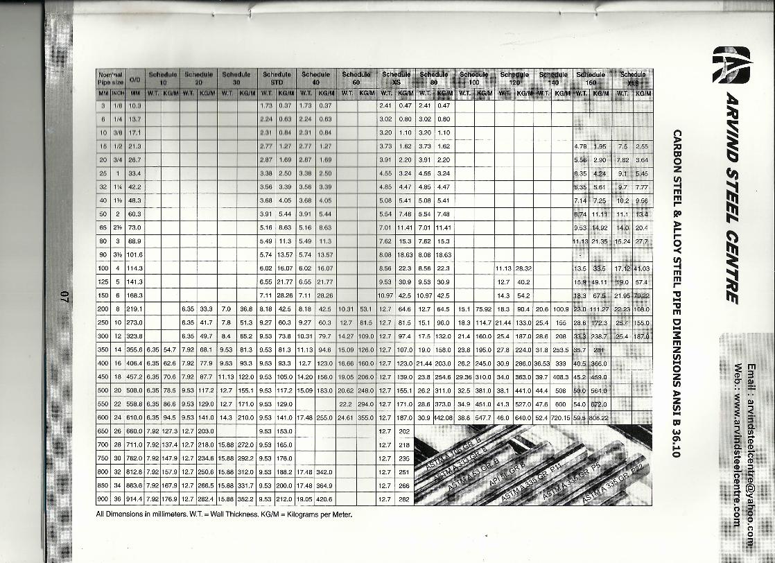
All Dimensions in millimeters. w.T. = Wall Thickness. KG/M = Kilograms per Meter.
6.55 121.77 I 6.55 121.77
9.53 1153.0
8.08 118.631 8.08 118.63
15.9 I 49.11 I 19.0 I 57.4
100 I 4 1114.3
1251 5 1141.3
8.56 I 22.3 I 8.56 I 22.3
9.53 I 30.9 I 9.53 I 30.9
11.13128.32 13.51 33.5 117.12141.03
12.7 I 40.2
150 I 6 1168.3 10.971 42.5 110.971 42.5 14.3 I 54.2 18.3167.5 121.95179.22
2001 8 1219.1 6.35 I 33.3 I 7.0 I 36.8 18.18 I 42.5 I 8.18 I 42.5 110.31 153.1 112.7 164.6 I 12.7 I 64.5 I 15.1 175.92 I 18.3 I 90.4 I 20.61100.9 123.01111.271 22.231108.0
250 I 10 1273.0 6.35141.7 I 7.8 151.3 19.27160.3 19.27 160.3 112.7 181.5112.7181.5115.1196.0 118.31114.7121.441133.0125.41 155 128.61172.3 125.4 1155.0
300 I 12 1323.8
350 I 14 1355.616.35154.7 17.92 I 68.1 19.53 I 81.3 19.53 181.3 111.131 94.6 115.09 1126.0112.7 1107.0 I 19.0 1158.0 I 23.8 1195.0 127.8 1224.0131.81253.5 135.71 281
400 I 16 1406.416.351 62.6 17.92 I 77.9 I 9.53 I 93.3 I 9.53 I 93.3 I 12.7 1123.0 116.66 1160.0 112.7 1123.0121.441203.0 1 26.2 1245.0 130.9 1286.0136.531 333 140.5 I 366.0
450 I 18 1457.216.35170.6 17.92 I 87.7 111.131122.019.53 1105.0114.201156.0 119.05 1206.0112.7 1139.0 I 23.8 1254.6 129.361310.0 134.0 1363.0139.71408.3 145.21459.0
500 I 20 1508.016.35178.5 19.53 1117.2 I 12.7 1155.1 19.53 1117.2 115.091183.0 120.62 1248.0112.7 1155.11 26.2 1311.0 I 32.5 1381.0 I 38.1 1441.0 I 44.41 508 150.0 I 564.0
5501221558.816.35186.619.531129.0112.71171.019.531129.0
600 I 24 1610.016.35194.5 19.531141.0114.3 1210.0 I 9.53 1141.0117.481255.0 124.61 1355.0112.7 1187.0 I 30.9 M2.081 38.8 1547.7146.0 1640.0152.41720.15159.51808.22
6.35149.7 I 8.4 165.2 19.53 173.8 110.31179.7 114.271109.0112.7 197.4 I 17.5 1132.0 I 21.4 1160.0 125.4 1187.0128.61 208 133.31238.7 I 25.4 1187.0
22.2 1294.0112.71171.0128.61373.0 I 34.9 1451.0141.31527.0147.61 600 154.01672.0
12.7 I 202
12.7 I 218
12.7 I 235
12.7 I 251
12.7 I 266
12.7 I 282
~
'"'"oz!!lmmr-RO»r-§!!lmmr-"tlI1-1"tlImC1-13:mZtn1-1oZtn»Ztn1-1
'"W0\•••••o
650 I 261660.017.921127.3112.71203.0
7001281711.017.921137.4112.71218.0115.881272.019.531165.0
750130 1762.017.921147.9112.71234.6115.881292.219.531176.0
8001321812.817.921157.9112.71250.6115.881312.019.531188.2117.481342.0
850 I 34 1863.617.921167.9112.71266.5 115.88 1331.7 I 9.53 1200.0 117.481364.9
900 I 36 1914.417.921176.9112.71282.4 115.881352.2 I 9.53 1212.0 119.051420.6
::E 1m(I) 3~ ~.
i~DI :i'< 0._. UI
:::::I -0.(1)UI (I)
S- o(I) (I)-:::::I(") -(I) @;a@@'<• C)("):ro 03 9
(")o3

MATERIAL SPECIFICATION FOR SEAMLESS/WELDED BUTT-WELDING PIPE-FITTINGS.I
II'~ CHIIMICAL PFlcfpERTIES I MECHANICAL ~RO~ER'(Jj;Sllil!i~~'F ,; ~:iii:l" 11 %
I S~ECIFlCATJONI P% 1% I U.T.S. V.S. ELONG. H~tdi\e<!.$ ~
OTHERS(,ASTM-2002) C% Mn% 11% Cl"% Mo% INIO/O (Mln) (Mln) (Mln) (Max).
I (Max) (MIX) Mpa Mpa L T BHN
STAINLESS STEEL
A 403 Gr. WP 304 0.080 Max 2.00 Max 0.045 O.OSO 1.00 Max 18.0-20.0 - 8.0-11.0 515 205 28 20
A 403 Gr. WP 304L 0.030 Max 2.00 Max 0.045 O.OSO 1.00 Max 18.0-20.0 - 8.0-12.0 485 170 28 20
A 403 Gr. WP 304H.0.04-0.10 2.00 Max 0.045 O.OSO 1.00 Mox 18.0-20.0 8.0-11.0 515 205 28 20- -
A 403 Gr. WP 304LN 0.030 Max 2.00 Max 0.045 O.OSO 1.00 Mox 18.0-20.0 - 8.0-11.0 515 205 28 20 - N%=0.10-0.16
A 403 Gr. WP 309 0.20 Max 2.00 Max 0.045 O.OSO 1.00 Mox 22.0-24.0 - 12.0-15.0 515 205 28 20 -A 403 Gr. WP 3108 0.080 Max 2.00 Max 0.045 O.OSO 1.00 Mox 24.0-26.0 - 19.0-22.0 515 205 28 20 -A 403 Gr. WP 316 0.080 Max 2.00 Max 0.045 O.OSO 1.00 Mox 16.0-18.0 2.0-3.0 10.0-14.0 515 205 28 20 -A 403 Gr. WP 316L 0.030 Max 2.00 Max 0.045 0.030 1.00 Max 16.0-18.0 2.0-3.0 10.0-14.0 485 170 28 20 --A 403 Gr. WP 316H 0.04-0.10 2.00 Max 0.045 0.030 1.00 Mox 16.0-18.0 2.0-3.0 10.0-14.0 515 205 28 20 -
A 403 Gr. WP 316LN 0.030 Max 2.00 Max 0.045 0.030 1.00 Max 16.0-18.0 2.0-3.0 10.0-13.0 515 205 28 20 - N%=0.10-0.16
A 403 Gr. WP 317 0.080 Max 2.00 Max 0.045 0.030 1.00 Mox 18.0-20.0 3.0-4.0 11.0-15.0 515 205 28 20 -A 403 Gr. WP 317L 0.030 Max 2.00 Max 0.045 0.030 1.00 Mox 18.0-20.0 3.0-4.0 11.0-15.0 515 205 28 20 -A 403 Gr. WP 321 0.080 Max 2.00 Max 0.045 0.030 1.00 Mox 17.0-19.0 - 9.0-12.0 515 205 28 20 - Ti%=(5XC)-0.70
A 403 Gr. WP 321 H 0.04-0.10 2.00 Max 0.045 0.030 1.00 Mox 17.0-19.0 - 9.0-12.0 515 205 28 20 - Ti%=(4XC)-0.70
A 403 Gr. WP 347 0.080 Max 2.00 Max 0.045 0.030 1.00 Mox 17.0-19.0 - 9.0-12.0 515 205 28 20 - Cb%=(10XC)-1.10
A 403 Gr. WP 347H 0.04-0.10 2.00 Max 0.045 0.030 1.00 Mox 17.0-19.0 - 9.0-12.0 515 205 28 20 - Cb%=(8XC)- 1.10
CARBON STEEL
A 234 Gr. WPB 0.30 Max 0.29-1.06 0.050 0.058 0.10 Mln 0.40 Max 0.15 Max 0.40 Max 415-655 240 30 20 197 Cu%=OAOMax,Va%=O.08Max,Cb%=0.02Max
A 234 Gr. WPC 0.35 Max 0.29-1.06 0.050 0.058 0.10 Mln 0.40 Max 0.15 Max 0.40 Max 485-655 275 30 20 197 Cu%=0.40Max,Va%:O.08Max,Cb%=0.02Max
LOW TEMPERATURE CARBON STEEL
A 420 Gr. WPL6 . 0.30 Max 0.50-1.35 0.035 0.040 0.15·0.40 0.30 Max 0.12 Max 0.40 Max 415-655 240 30 16.5 197Cu%=OAOMax,Va%=O.08Max,Cb%=0.02Max
ImpactTesl=·45'C,J=17.3·13·6
A 420 Gr. WPL 3 0.20 Max 0.31-0.64 0.050 0.050 0.13-0.S7 - - 3.20-3.80 450-620 240 30 20 197 ImpactTest=·45'C,J=17.3·13·6
ALLOY STEEL
A 234 Gr. WP 1 0.28 Max 0.30-0.90 0.045 0.045 0.10-0.50 - 0.44-0.65 - 380-550 205 30 20 197
A234 Gr. WP5 0.15 Max 0.30-0.60 0.040 0.030 0.50 Max 4.0-6.0 0.44-0.65 - 415-585 205 30 20 217
A 234 Gr. WP9 0.15 Max 0.30-0.60 0.030 0.030 1.00 Max 8.0-10.0 0.90-1.10 - 415-585 205 30 20 217
A 234 Gr. WP 11 CL 1 0.05-0.15 0.30-0.60 0.030 0.030 0.50-1.0 1.0-1.5 0.44-0.65 - 415-585 205 30 20 197
A 234 Gr. WP 11 CL2 0.05-0.20 0.30-0.80 0.040 0.040 0.50-1.0 1.0-1.5 0.44-0.65 - 485-655 275 30 20 197
A 234 Gr. WP 11 CL3 0.05-0.20 0.30-0.80 0.040 0.040 0.50-1.0 1.0-1.5 0.44-0.65 - 520-690 310 30 20 197
A 234 Gr. WP 12 CLl 0.05-0.20 0.30-0.80 0.045 0.045 0.60 Max 0.80-1.25 0.44-0.65 - 415-585 220 30 20 197
A 234 Gr. WP 12 CL2 0.05-0.20 0.30-0.80 0.045 0.045 0.60 Max 0.80-1.25 0.44-0.65 - 485-655 275 30 20 197
A 234 Gr. WP 22 CL 1 0.05-0.15 0.30-0.60 0.040 0.040 0.50 Max 1.90-2.60 0.87-1.13 - 415-585 205 30 20 197
A 234 Gr. WP 22 CL3 0.05-0.15 0.30'0.60 0.040 0.040 0.50 Max 1.90-2.60 0.87-1.13 - 520-690 310 30 20 197 ;
A 234 Gr. WP 91 0.08-0.12 0.30-0.60 0.020 0.010 0.20-0.50 8.0-9.5 0.85-1.05 0.40 Max 585-760 415 20 - 248Va%:O.18-0.25,Cb%:O.06.Q.10,N%:O.03.().07,AI%--o.04Max
e(X)
'"c=II:e
mr-C••••Z~'TI••••=I••••z~(I)
»~J:
~
~
~fI)
~I!!~
~
~
:!Em(1) 3~ ~.
I~ill S':< 0.._. (II
:::I -o..(1)t/I !.CD o(1) (1)-:::I(') ==r(1) (1)a@a'<• Q)(') ::ro 03 ?
(')o3
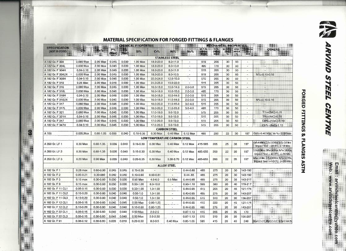
MATERIAL SPECII7ICATION FOR FORGED FITTINGS & FLANGES,.........~, ~"P"""E"'.S ._51% I (:r%, 'Ni~/~ii,-
'Ox , ' "~imrni:xiiSTAINLESS STEEL
A 182 Gr. F 304 0.080 Max 2.00 Max 0.045 0.030 1.00 Max 18.0-20.0 8.0-11.0 - 515 205 30 50 -A 182 Gr. F 304L 0.030 Max 2.00 Max 0.045 0.030 1.00 Max 18.0-20.0 8.0-13.0 485 170 30 50 - -A 182 Gr. F 304H 0.04-0.10 2.00 Max 0.045 0.030 1.00 Max 18.0-20.0 8.0-11.0 515 205 30 50 -A 182 Gr. F 304LN . 0.030 Max 2.00 Max 0.045 0.030 1.00 Max 18.0-20.0 8.0-10.5 515 205 30 50 - N%=0.10-0.16A 182 Gr. F 309H 0.04-0.10 2.00 Max 0.045 0.030 1.00 Max 22.0-24.0 12.0-15.0 - 515 205 30 50
A 182 Gr. F 310 0.25 Max 2.00 Max 0.045 0.030 1.00 Max 24.0-26.0 19.0-22.0 - 515 205 30 50A 182 Gr. F 316 0.080 Max 2.00 Max 0.045 0.030 1.00 Max 16.0-18.0 10.0-14.0 2.0-3.0 515 205 30 50 -A 182 Gr. F 316L 0.030 Max 2.00 Max 0.045 0.030 1.00 Max 16.0-18.0 10.0-15.0 2.0-3.0 485 170 30 50A 182 Gr. F 316H 0.04-0.10 2.00 Max 0.045 0.030 1.00 Max 16.0-18.0 10.0-14.0 2.0-3.0 515 205 30 50 -A 182 Gr. F 316LN 0.030 Max 2.00 Max 0.045 0.030 1.00 Max 16.0-18.0 11.0-14.0 2.0-3.0 515 205 30 50 N%=0.10-0.16A 182 Gr. F 317 0.080 Max 2.00 Max 0.045 0.030 1.00 Max 18.0-20.0 11.0-15.0 3.0-4.0 515 205 30 50A 182 Gr. F 317L 0.030 Max 2.00 Max 0.045 0.030 1.00 Max 18.0-20.0 11.0-15.0 3.0-4.0 485 170 30 50 -A 182 Gr. F 321 0.080 Max 2.00 Max 0.045 0.030 1.00 Max 17.0-19.0 9.0-12.0 - 515 205 30 50 Ti%=(5xC)-0.70
A 182 Gr. F 321 H 0.04-0.10 2.00 Max 0.045 0.030 1.00 Max 17.0-19.0 9.0-12.0 - 515 205 30 50 - Ti%=( 4xC)-0. 70
A 182 Gr. F 347 0.080 Max 2.00 Max 0.045 0.030 1.00 Max 17.0-20.0 9.0-13.0 515 205 30 50 - Cb%=(10xC)"1.10A 182 Gr. F 347H 0.04-0.10 2.00 Max 0.045 0.030 1.00 Max 17.0-20.0 9.0-13.0 515 205 30 50 Cb%=18xC)-1.10
CARBON STEELA 105 0.035,Max 0.60-1.05 0.035 0.040 0.10-0.35 0.30 Max 0.40 Max 0.12 Max 485 250 22 30 187 Cu%=0.40 Max, Va %= 0.08 Max
LOW TEMPERATURE CARBON STEEL
A 350 Gr. LF 1 0.30 Max 0.60-1.35 0.035 0.040 0.15-0.30 0.30 Max 0.40 Max 0.12 Max 415-585 205 25 38 197 CU%:{).40Max, Cb%:{).02 Max, Va %= 0.05 Max,Impact Test =-28.9°C, J=18 Min
A 350 Gr. LF 2 0.30 Max 0.60-1.35 0.035 0.040 0.15-0.30 0.30 Max 0.40 Max 0.12 Max 485-655 250 22 30 197Cu%:{).40Max, Cb%:{).02 Max, Va %= 0.05 Max,
Impact Test =-45.6°C, J=18 Min
A 350 Gr. LF 3 0.20 Max 0.90 Max 0.035 0.040 0.20-0.35 0.30 Max 3.30-3.70 0.12 Max 485-655 260 22 35 197 Cu%:{).40Max, Cb%=0.02 Max, Va %~ 0.03 Max,Impact Test =-101 'c, J=20 Min
ALLOY STEEL ,A182Gr.F1 0.28 max 0.60-0.90 0.045 0.045 0.15-0.35 - - 0.44-0.65 485 275 20 30 143-192
A182Gr.F2 0.05-0.21 0.30-080 0.040 0.040 0.10-0.60 0.50-0.81 0.44-.65 485 275 20 30 143-192
A 182 Gr. F 5 0.15 max 0.30-0.60 0.030 0.030 0.50 Max 4.0-6.0 0.5 Max 0.44-0.65 485 275 20 35 143-217; x
A 182 Gr. F9 0.15 max 0.30-0.60 0.030 0.030 0.50-1.00 8.0-10.0 0.90-1.10 585 380 20 40 179-217 -'"
A 182 Gr. F 11 CL 1 0.05-0.15 0.30-0.60 0.030 0.030 0.50-1.00 1.0-1.50 0.44-0.65 415 205 20 45 121-174
A 182 Gr. F 11 CL2 0.10-0.20 0.30-0.80 0.040 0.040 0.50-1.0 1.0-1.50 - 0.40-0.65 485 275 20 30 143-207
A182Gr.F11 CL3 0.10-0.20 0.30-0.80 0.040 0.040 0.50-1.0 1.0-1.50 - 0.44-0.65 515 310 20 30 156-207 -A 182 Gr. F 12 CL1 0.05-0.15 0.30-0.60 0.045 0.045 0.50 Max 0.80-1.25 - 0.44-0.65 415 220 20 45 121-174
~..
A 182 Gr. F 12 CL2 0.10-0.20 0.30-0.80 0.040 0.040 0.10-0.60 0.80-1.25 0.44-0.65 485 275 20 30 143-207 -A 182 Gr. F 22 CL1 0.05-0.15 0.30-0.60 0.040 0.040 0.50 Max 2.0-2.5 0.87-1.13 415 205 20 35 170
A 182 Gr. F 22 CL3 0.05-0.15 0.30-0.60 0.040 0.040 0.50 Max 2.0-2.50 0.87-1.13 515 310 20 30 156-207
A 182 Gr. F91 0.08-0.12 0.30-0.60 0.020 0.010 0.20-0.50 8.0-9.5 0.40 Max 0.85-1.05 585 415 20 40 248 Cb%=0.06.().10, N%=O.03-0.07, Va %= 0.18-0.25
."o~mC."1-1
:::J1-1ZCi)tn120.">ZCi)mtn
~3:
~.;~A'~",~~
~
~fI)
~
~
~
~
~
:Em(I) 3?" !-
i~~ :5-< 0.__ en;:::J <D0.(1)en --(')(I) (I)(I) ;:::J-,...(') .,(I) (I)a@@'<- I»(') :ro 03 !=>
oo3
CHEMICAL PROPERTIES I MECHANICAL PROPERTIES
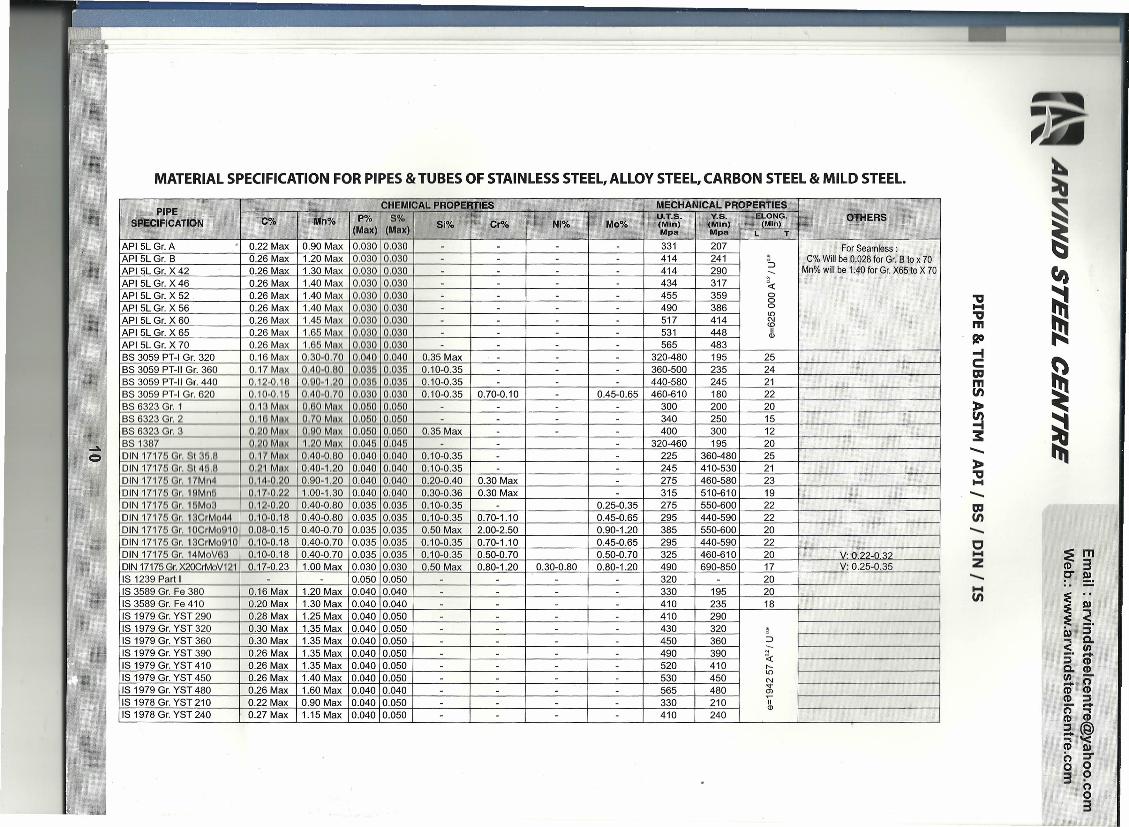
MATERIAL SPECIFICATION FOR PIPES & TUBES OF STAINLESS STEEL, ALLOY STEEL, CARBON STEEL & MILD STEEL.
<\"C%PIPE
SPECIFICATION 0'M I po, 'I SOl I I"" U.T.S. I V.S."' n% '0 ,0 81% Cr%'h' NI% Moo;. (NUn) (Mln)(Max) (Max) Mpa Mpa
~
API 5L Gr. X 52 0.26 Max 1.40 Max 0.030 0.030 - - - - 455 359API 5L Gr. X 56 0.26 Max 1.40 Max 0.030 0.030 - - - - 490 386API 5L Gr. X 60 0.26 Max 1.45 Max 0.030 0.030 - - - - 517 414
IAPI 5L Gr. X 65 0.26 Max 1.65 MA~ Q..O~o 0.030 - - - - 531 448API 5L Gr. X 70 0.26 Max 1.65 MAli ~<L 0.030 - - - - 565 483BS 3059 PT-I Gr. 320 0.16 Max 0.30-0.70 0.040 0.040 0.35 Max - - - 320-480 195 25
IBS 3059 PT-II Gr. 360 0.17 MnL~Qj9 Q..6~ ~ 0.10-0.35 - - - 360-500 235 24 I IIBS 3059PT-1I Gr. 440 0.12-0.100.J)0-ULO 0.•..031,5Q.QM... 0.10-0.35 - - - 440-580 245 21 I IBS 3059 PT-I Gr. 620 0.10-0.16 0.1\0-0,70 0.030 0.030 0.10-0.35 0.70-0.10 - 0.45-0.65 460-610 180 22BS 6323 Gr. 1 QJ~Mnlt MO Mnx QMQ ° 060 - - - - 300 200 20BS 6323 Gr. 2 _ o...1nMNt Q.1Q11nx.. 0.060 0060 - - - - 340 250 15BS 6323 Gr. ~ • O,JO .M.">I. O,JlOMnx 10.060,.Q,:Q§Q.. 0.35 Max - - - 400 300 12BS 1387 _ _ __ • ~ Mnli .1c~.MAX 0.045 0.045 - - - 320-460 195 20DIN 17175 [email protected]!.3(!,fl 0.•..1'1 Mnl!.. 0.40-0.80 0.040 0.040 0.10-0.35 - - 225 360-480 25DIN 17176 Gr, 914(3,11 ()'~1 MAX 0.40·1.20 0.040 0.040 0.10-0.35 - - 245 410-530 21DIN 17176Clr,. 1Ifi.1l)~ OL14-Q.6Q... 0.90-1.20 0.040 0.040 0.20-0.40 0.30 Max - 275 460-580 23
IDIN 17175 Gr. 10Mn" 0.Ji'-0.22 1.00-1.30 0.040 0.040 0.30-0.36 0.30 Max - 315 510-610 19DIN 17176 Gr. 1GMQrJ 0.12-0.20 0.40-0.80 0.035 0.035 0.10-0.35 - 0.25-0.35 275 550-600 22DIN 17176 Gr,1~'~14 0.10-0.18 0.40-0.80 0.035 0.035 0.10-0.35 0.70-1.10 0.45-0.65 295 440-590 22
IDIN 17175 Gr. 10CrMoM6 0.08·0.15 0.40-0.70 0.035 0.035 0.50 Max 2.00-2.50 0.90-1.20 385 550-600 20DIN 17175 Gr:-13CrMo010 0.10-0.18 0.40-0.70 0.035 0.035 0.10-0.35 0.70-1.10 0.45-0.65 295 440-590 22 I IDIN 17175 Gr. 14MoV83 . 0.10-0.18 0.40-0.70 0.035 0.035 0.10-0.35 0.50-0.70 0.50-0.70 325 460-610 20 I V: 0.2:>-0::\/DIN 17175Gr.X20CrMoV121 0.17-0.23 1.00 Max 0.030 0.030 0.50 Max 0.80-1.20 0.30-0.80 0.80-1.20 490 690-850 17 I V: 0.25-0.35
API 5L Gr. A -I 0.22 Max I 0.90 Max 10.030 10.030 I I - 331 I 207API 5L Gr. B I 0.26 Max I 1.20 Max 10.030 10.030 I I I 414 I 241API 5L Gr. X 42 I 0.26 Max I 1.30 Max 10.030I0.030 I I I I I 414 I 290API 5L Gr. X 46 I 0.26 Max I 1.40 Max 10.030 10.030 I I I 434 I 317
..•..Q
OTHERS
---~oooioC\J<DII
Ql
ForSeamless:C%Willbe0.028for Gr.B to x 70
Mn%will be 1.40for Gr.X65to X 70
IS 1239 Part I I I 10.05010.0501 I I I 1320 I I 20IS 3589 Gr. Fe 380 I 0.16Max I 1.20 Max 10.04010.040 I I I I I 330 I 195 I 20IS 3589 Gr. Fe410 I 0.20Max I 1.30 Max 10.Q4010.040 I I I 410 I 235 I 18IS 1979 Gr. YST 290 I 0.28 Max I 1.25 Max 10.040 10.050 I I I I I 410 I 290IS 1979 Gr. YST 320 I 0.30 Max I 1.35 Max I0.040 10.050 I I I 430 320IS 1979 Gr. YST 360 I 0.30 Max I 1.35 Max 10.040 10.050 I I I 1 I 450 I 360IS 1979 Gr. YST 390 1 0.26 Max 11.35 Max 10.040 10.050 I 1 1 I 490 390IS 1979 Gr. YST410 1 0.26Max 11.35 Max 10.04010.050 I 1 I I 520 410IS 1979 Gr. YST 450 I 0.26 Max I 1.40 Max 10.04010.050 1 1 1 1 1 530 1 450IS 1979 Gr. YST 480 1 0.26 Max 1 1.60 Max 10.040 10.040 I I I I I 565 480IS 1978 Gr. YST 210 1 0.22 Max 10.90 Max 10.04010.050 I I I I 1 330 1 210IS 1978 Gr. YST240 1 0.27Max 11.15Max 10.04010.050 1 1 1 1 410 240
~::>---~r-;ioN-a;ItQl
"a••••"am~-tCmm(I)
~3:....••»"a••••....••m(I)....••c••••Z....••••••(I)
~
~
~
~
~I!!~
~
~
::Em(I) 3?" ~ .
i~.Q) ::::s< 0.._. tII::::s -0..(1)tII ~(to(I) (I)_::::so -(I) @;a.@""'<~ Q)o :::To 03 !=>
oo3
'i':-~>. .-
"" .';' -sl' ."..••. ra
't'~
-
..•..•
ASTMA210 Gr. A1
~ i t t=:
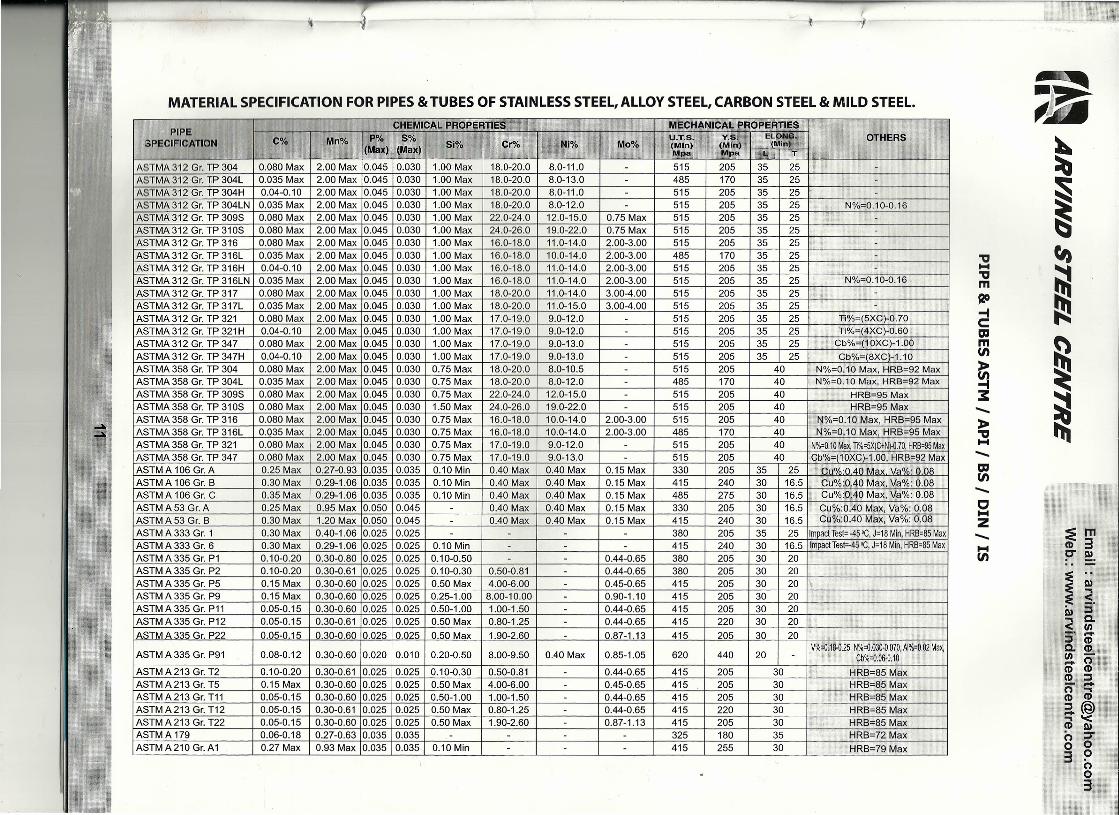
MATERIAL SPECIFICATION FOR PIPES & TUBES OF STAINLESS STEEL, ALLOY STEEL, CARBON STEEL & MILD STEEL.
PIPESPECIFICATION OTHERS
CHEMICAL IPROPERTIES MECHANICAL PROPERTIES
HRB=79 Max
C% Mn% 1 Po;.(Max)
So;.(Max) SI% Cr% ••
NI% Mo%U.T.S.(Mln)MpSdi
V:S.(Mln)Mpa
ELONG.(Min)
L/. T
ASTMA 312 Gr. TP 304 0.080 Max 2.00 Max 10.045 0.030 1.00 Max 18.0-20.0 8.0·11.0 515 205 35 25
N%=0.10-0.16
ASTMA 312 Gr. TP 304L 0.035 Max 2.00 Max 10.045 0.030 1.00 Max 18.0-20.0 8.0-13.0 485 170 35 25ASTMA 312 Gr. TP 304H 0.04-0.10 2.00 Max 10.045 0.030 1.00 Max 18.0-20.0 8.0-11.0 515 205 35 25
25
ASTM,A. 312 Gr. TP 304LN 0.0.35 Max 2.00 Max 10.045 0.030 1.00 Max 18.0-20.0 8.0-12.0 515 205 35 25
25
ASTMA 312 Gr. TP 309S 0.080 Max 2.00 Max 10.045 0.030 1.00 Max 22.0-24.0 12.0-15.0 0.75 Max 515 205 35 25
25
ASTMA 312 Gr. TP 310S 0.080 Max 2.00 Max 10.D45 0.030 1.00 Max 24.0-26.0 19.0-22.0 0.75 Max 515 205 35
25
ASTMA 312 Gr. TP 3t6 0.080 Max 2.00 Max 10.045 0.030 1.00 Max 16.0-18.0 11.0-14.0 2.00-3.00 515 205 35
25 N%=0.10-0.16
ASTMA 312 Gr. TP 316L 0.035 Max 2.00 Max 10.045 0.030 1.00 Max 16.0-18.0 10.0-14.0 2.00-3.00 485 170 35ASTMA 312 Gr. TP 316H 0.04-0.10 2.00 Max 10.045 0.030 1.00 Max 16.0-18.0 11.0-14.0 2.00-3.00 515 205 35
25
ASTMA 312 Gr. TP 316LN 0.035 Max 2.00 Max 10.045 0.030 1.00 Max 16.0-18.0 11.0-14.0 2.00-3.00 515 205 35ASTMA 312 Gr. TP 317 0.080 Max 2.00 Max 10.045 0.030 1.00 Max 18.0-20.0 11.0-14.0 3.00-4.00 515 205 35 25
Ti%=(5XC)-O.70ASTMA 312 Gr. TP 317L 0.035 Max 2.00 Max 10.D45 0.030 1.00 Max 18.0-20.0 11.0-15.0 3.00-4.00 515 205 35ASTMA 312 Gr. TP 321 0.080 Max 2.00 Max 10.045 0.030 1.00 Max 17.0-19.0 9.0-12.0 515 205 35 25
25 Cb%=(10XC)-1.00ASTMA 312 Gr. TP 321 H 0.04-0.10 2.00 Max 10.045 0.030 1.00 Max 17.0-19.0 9.0-12.0 515 205 35 25 Ti%=(4XC)-0.60
Cb%=(8XC)-1.10ASTMA312 Gr. TP 347 0.080 Max 2.00 Max 10.045 0.030 1.00 Max 17.0-19.0 9.0-13.0 515 205 35
ASTMA 358 Gr. TP 30440 N%=O.10 Max. HRB=92 Max
ASTMA 312 Gr. TP 347H 0.04-0.10 2.00 Max 10.045 0.030 1.00 Max 17.0-19.0 9.0-13.0 515 205 35 250.080 Max 2.00 Max 10.045 0.030 0.75 Max 18.0-20.0 8.0-10.5 515 205 40 N%=0.10 Max, HRB=92 Max
ASTMA 358 Gr. TP 304L 0.035 Max 2.00 Max 10.045 0.030 0.75 Max 18.0-20.0 8.0-12.0 485 170ASTMA 358 Gr. TP 309S 0.080 Max 2.00 Max 10.045 0.030 0.75 Max 22.0-24.0

Email: [email protected].: www.arvindsteelcentre.comARVIND STEEL CENTRE
DIMENSIONS OF FORGED FLANGES ANSI 16.5
----!ot-
SLIP-ON FLANGE BLIND FLANGEWELDING NECK FLANGE
ASA 150 CLASS
(15 1/2 88.9 60.3 15.9 4 11.1 30.2 15.9 47.6 15.9 22.3 22.9 34.9 9.5 21.3320 3/4 98.4 69.8 15.9 4 12.7 38.1 15.9 52.4 15.9 27.7 28.2 42.9 11.1 26.6725 1 107.9 79.4 15.9 4 14.3 49.2 17.5 55.6 17.5 34.5 35.0 50.8 12.7 33.4032 11/4 117.5 88.9 15.9 4 15.9 58.7 20.6 57.1 20.6 43.2 43.7 63.5 14.3 42.1640 1 1/2 127.0 98.4 15.9 4 17.5 65.1 22.2 61.9 22.2 49.5 50.0 73.0 15.9 48.2650 2 152.4 120.6 19.0 4 19.0 77.8 25.4 63.5 25.4 62.0 62.5 92.1 17.5 60.3165 21/2 177.8 139.7 19.0 4 22.2 90.5 28.6 69.8 28.6 74.7 75.4 104.8 19.0 73.0280 3 ' 190.5 152.4 19.0 4 23.8 107.9 30.2 69.8 30.2 90.7 91.4 127.0 20.6 88.90100 4 228.6 190.5 19.0 8 23.8 134.9 33.3 76.2 33.3 116.1 116.8 157.2 23.8 114.30125 5 254.0 215.9 22.2 8 23.8 163.5 36.5 88.9 36.5 143.8 144.5 185.7 23.8 141.30150 6 279.4 241.3 22.2 8 25.4 192.1 39.7 88.9 39.7 170.7 171.4 215.9 27.0 168.27200 8 342.9 298.4 22.2 8 28.6 246.1 44.4 101.6 44.4 221.5 222.2 269.9 31.7 219.07250 10 406.4 361.9 25.4 12 30.2 304.8 49.2 101.6 49.2 276.3 277.4 323.8 33.3 273.05300 12 482.6 431.8 25.4 12 31.8 365.1 55.6 114.3 55.6 327.1 328.2 381.0 39.7 323.85350 14 533.4 476.2 28.6 12 34.9 400.0 57.1 127.0 79.4 359.1 360.2 412.7 4'k3 355.60400 16 596.9 539.7 28.6 16 36.5 457.2 63.5 127.0 87.3 410.5 411.2 469.9 44.4 406.40450 18 635.0 577.8 31.7 16 39.7 504.8 68.3 139.7 96.8 461.8 462.3 533.4 49.2 457.20500 20 698.5 635.0 31.7 20 42.9 558.8 73.0 144.5 103.2 513.1 514.3 584.2 54.0 508.00600 24 812.8 749.3 34.9 20 47.6 663.6 82.5 152.4 111.1 615.9 615.9 692.1 63.5 609.60
AllDimensionsare inMillimeters. FlangesexceptLapJointwillbe furnishedwith(1.6mm)RaisedFace,whichis includedinThickness(C)and LenghtthroughHub(Y).
ASA 300 CLASSNomnIt Range Diaof Diaaf No. of TlIkaf Diaaf Length llvougfi Huti Dia of Bore Diaof
Pipe Dia Bolt Boll Holes Ringe Hub R/FSize Cin:Ie Holes SIO&SIW WIN UJ SIO&SIW LlJ
~ 1(llCH.) 0 A D C E - Y Y y B B R F'"15 I 112 I 952 I 66.7 I 15.9 4 14.3 38.1 22.2 52.4 22.2 22.3 22.9 34.9 9.5 21.3320 1314 I 117.5 82..5 19.0 4 15.9 47.6 25.4 57.1 25.4 27.7 28.2 42.9 11.1 26.6725 I 1 I 123.8 88.9 19.0 4 17.5 54.0 27.0 61.9 27.0 34.5 35.0 50.8 12.7 33.4032 111/4 133.3 98.4 19.0 4 19.0 63.5 27.0 65.1 27.0 43.2 43.7 63.5 14.3 42.1640 1 112 155.6 114.3 22.2 4 20.6 69.8 30.2 68.3 30.2 49.5 50.0 73.0 '15.9 48.2650 2 165.1 127.0 19.0 8 22.2 84.1 33.3 69.8 33.3 62.0 62.5 92.1 17.5 60.3165 21/2 190.5 149.2 22.2 8 25.4 100.0 38.1 76.2 38.1 74.7 75.4 104.8 19.0 73.0280 3 209.5 168.3 22.2 8 28.6 117.5 42.9 79.4 42.9 90.7 91.4 127.0 20.6 88.90100 4 254.0 200.0 22.2 8 31.8 146.0 ,47.6 85.7 47.6 116.1 116.8 157,2 23.8 114,30125 5 279.4 234.9 22.2 8 34.9 177.8 50.8 98.4 50.8 143.8 144.5 185.7 - 141.30150 6 317.5 269.9 22.2 12 36.5 206.4 52.4 98.4 52.4 170.7 171.4 215,9 168.27200 8 381.0 330,2 25.4 12 41.3 260.3 61.9 111.1 61.9 221.5 222.2 269.9 - 219.07250 10 444.5 387.3 28.6 16 47.6 320.7 66.7 117.5 95.2 276.3 277.4 323.8 273.05300 12 520.7 450.8 31.7 16 50.8 374.6 73.0 130,2 101.6 327.1 328.2 381.0 - 323.85350 14 584.2 514.3 31.7 20 54.0 425.4 76.2 142.9 111.1 359.1 360.2 412.7 355.60400 16 647.7 571.5 34.9 20 57.2 482.6 82,5 146,0 120.6 410.5 411.2 469,9 - 406.40450 18 711.2 628.5 34.9 24 60.3 533.4 88.9 158.7 130.2 461.8 462.3 533.4 - 457.20500 20 774.7 685.8 34.9 24 63.5 587.4 95.2 161.9 139.7 513.1 514.3 584.2 - 508.00600 24 914.4 812.8 41.3 24 69.8 701.7 106.4 168.3 152.4 6.15.9 615.9 692.1 - 609.60
AI Dnensions are inMillimeters. FlangesexceptLapJointwillbe furnishedwith(1.6mm)RaisedFace,whichis includedinThickness(C)and LenghtthroughHub(Y).

~ ARVIND STEEL CENTRE.~ Email: [email protected].: www.arvindsteelcentre.com
DIMENSIONS OF CLASS 600 FLANGES AS PER ANSI B 16.5
WELD·NECK SCREWED LAPPED
N.B. A B C 0 E F G H J K L M N 0 P R T ~ No.ofHoles
-15 95 14.3 6.4 35 22 38 22.4 9.5 21.3 23.5 52 16 22 23.0 66.7 3.0 15.9 420 117 15.9 6.4 43 25 48 27.7 11.0 26.7 29.0 57 16 25 28.0 82.6 3.0 19.0 425 124 17.5 6.4 51 27 54 34.5 12.5 33.4 36.0 62 17 27 35.0 88.9 3.0 19.0 432 133 20.6 6.4 64 29 64 43.2 14.5 42.2 44.5 67 21 29 43.5 98.4 5.0 19.0 440 156 22.2 6.4 73 32 70 49.5 16.0 48.3 50.5 70 22 32 50.0 114.3 6.5 22.2 450 165 25.4 6.4 92 37 84 62.0 17.5 60.3 63.5 73 29 37 62.5 127.0 8.0 19.0 865 190 28.6 6.4 105 41 100 74.7 19.0 73.0 76.0 79 32 41 75.5 149.2 8.0 22.2 880 210 31.8 6.4 127 46 117 90.7 20.5 88.9 92.0 83 35 46 91.5 168.3 9.5 22.2 890 229 34.9 6.4 140 49 133 103.4 · 101.6 105.0 86 40 49 104.0 184.2 9.5 25.4 8100 273 38.1 6.4 157 54 152 116.1 · 114.3 118.0 102 41 54 117.0 215.9 11.0 25.4 8125 330 44.4 6.4 186 60 189 143.8 · 141.3 145.0 114 48 60 145.0 266.7 11.0 28.6 8150 356 47.6 6.4 216 67 222 170.7 · 168.3 171.0 117 51 67 171.0 292.1 12.5 28.6 12200 419 55.6 6.4 270 76 273 221.5 · 219.1 222.0 133 57 76 222.0 349.2 12.5 31.8 12250 508 63.5 6.4 324 86 343 276.4 · 273.0 276.0 152 65 111 277.0 431.8 12.5 34.9 16300 559 66.7 6.4 381 92 400 327.2 · 323.9 329.0 156 70 117 328.0 489.0 12.5 34.9 20350 603 69.8 6.4 413 94 432 359.2 · 355.6 360.0 165 73 127 360.0 527.0 12.5 38.1 20400 686 76.2 6.4 470 106 495 410.5 · 406.4 411.0 178 78 140 411.0 603.2 12.5 41.3 20450 743 82.6 6.4 533 117 546 461.8 · 457.2 462.0 184 79 152 462.0 654.0 12.5 44.4 20500 813 88.9 6.4 584 122 610 513.1 · 508.0 513.0 190 83 165 514.0 723.9 12.5 44.4 24600 940 101.6 6.4 692 140 718 616.0 · 609.6 614.0 203 92 184 616.0 838.2 12.5 50.8 24
DIMENSIONS OF CLASS 900 FLANGES AS PER ANSI B 16.5
.,i~· ~ .K \';11\ -.;~A. p ··~~Il~li··~N.B. A B C 0 E G M~:Ii, N ~15 121 22.2 6.4 35 32 38 22.4 9.5 21.3 23.5 60 22 32 23.0 82.6 3.0 22.2 420 130 25.4 6.4 43 35 44 27.7 11.0 26.7 29.0 70 25 35 28.0 88.9 3.0 22.2 4
25 149 28.6 6.4 51 41 52 34.5 12.5 33.4 36.0 73 29 41 35.0 101.6 3.0 25.4 4
32 159 28.6 6.4 64 41 64 43.2 14.5 42.2 44.5 73 30 41 43.5 111.1 5.0 25.4 440 178 31.8 6.4 73 44 70 49.5 16.0 48.3 50.5 83 32 44 50.0 123.8 6.5 28.6 450 216 38.1 6.4 92 57 105 62.0 17.5 60.3 63.5 102 38 57 62.5 165.1 8.0 25.4 865 244 41.3 6.4 105 64 124 74.7 19.0 73.0 76.0 105 48 64 75.5 190.5 8.0 28.6 880 267 47.6 6.4 127 73 133 · · 88.9 92.0 117 51 73 91.5 203.2 9.5 31.8 8
·100 311 54.0 6.4 157 91 162 · 114.3 118.0 124 57 91 117.0 241.3 11.0 34.9 8
125 325 73.0 6.4 186 105 197 · 141.3 145.0 156 64 105 145.0 292.1 11.0 41.3 8150 394 82.6 6.4 216 119 229 · 168.3 171.0 171 70 119 171.0 317.5 12.5 38.1 12
200 483 92.1 6.4 270 143 292 · · 219.1 222.0 213 75 143 222.0 393.7 12.5 44.4 12
250 584 108.0 6.4 324 159 368 · · 273.0 276.0 254 84 178 277.0 482.6 12.5 50.8 12300 673 123.8 6.4 381 181 451 · 323.9 329.0 283 92 219 328.0 571.5 12.5 54.0 16350 749 133.4 6.4 ,413 495 · 356.6 · 298 . 241 360.0 635.0 12.5 60.3 16400 826 146.1 6.4 470 552 · 406.4 · 311 . 260 411.0 704.8 12.5 66.7 16450 914 161.9 6.4 533 597 · · 457.2 327 - 276 462.0 774.7 12.5 73.0 16
500 984 178.0 6.4 584 641 · 508.0 - 356 - 292 514.0 831.8 12.5 79.4 16
600 168\203.0 6.4 692 762 - - 609.6 · 406 - 330 616.0 990.6 12.5 92.0 16
1) All dImensions are in Millimeters2) Flanges excepll...ap Joint will be furnished with (1.6) Raised Face, which is included in "Thickness(C)" and "Length through Hub(Y)".
13

WD STEEL CENTREEmail: [email protected].: www.arvindsteelcentre.com .
DIMENSIONS OF FORGED FLANGES ANSI B 16.5
Nominal Flange Dla of Dlaof No. of Thkof Diaof Length Through Hub Dia of Bore Diaof Depth of PipePipe Dia Bolt Bolt Holes Flange Hub RIF Socket Dia
Size Circle Holes s/O&SIW WIN UJ 5/0 & SIW UJ
(MM) I(INCH.) 0 A D C E Y Y Y B B R F X
For Dimensions from 1/2" to 21/2" kindly refer ASA 900 LBS Table.
80 3 266.7 203.2 31.7 8 47.6 133.3 73.0 117.5 73.0 90.7 91.4 127.0 - 88.90
100 4 311.1 241.3 34.9 8 54.0 161.9 90.5 123.0 90.4 116.1 116.8 157.2 - 114.30
125 5 374.6 292.1 41.3 8 73.0 196.8 104.8 155.6 104.8 143.8 144.5 185.7 - 141.30
150 6 393.7 317.5 38.1 12 82.6 228.6 119.1 171.4 119.1 170.7 171.4 215.9 - 168.27
200 8 482.6 393.7 44.4 12 92.1 292.1 142.9 212.7 142.8 221.5 222.2 269.9 - 219.07
250 10 584.2 482.6 50.8 12 107.9 368.3 158.7 254.0 177.8 276.3 277.3 323.8 - 273.05
300 12 673.1 571.5 54.0 16 123.8 450.8 181.0 282.5 218.9 327.1 328.1 381.0 - 323.85
All Dimensions are in Millimeters. Flanges except Lap Joint will be furnished with(6.35mm) Raised Face, which is not included in Thickness(C) and Lenght through Hub(Y).
Nominat'· Flange ThkOf.st..++
PipeDla of DJaof No. of Die of Length Throu!l~~Hub Dia of Bore oia ',DepthofPipe [lia Bolt Bolt Holes Flange Hub RIF Socket Dla
Size Circle Holes s/O&SIW WIN UJ s/O&SIW UJI .
(MY) (INCH.) w 0 A D 1"•.v'C E y Y.. y B B A F ·X
15 1/2 133.3 88.9 22.2 4 30.2 42.9 39.7 73.0 39.7 22.3 22.3 34.9 - 21.33..
20 3/4 139.7 95'.3 22.2 4 31.7 50.8 42.9 79.4 42.9 27.7 27.7 42.9 - 26.67
25 1 158.7 107.9 25.4 4 34.9 57.1 47.7 88.9 47.7 34.5 34.5 50.8 - 33.40
32 1 1/4 184.1 .130.2 28.6 4 38.1 73.0 52.4 95.2 52.4 43.2 43.2 63.5 - 42.16
40 1 1/2 203.2- 146.0 31.7 4 44.4 79.4 60.3 111.1 60.3 49.5 49.5 73.0 - 48.26
50 2 - 234.9 171.4 28.6 8 50.8 95.2 69.8 127.0 69.8 62.4 62.0 92.1 - 60.31
65 21/2 266.7 196.8 31.7 8 57.1 114.3 79.4' 142.9 79.4 74.7 74.7 104.8 - 73.02
80 3 304.8 228.6 34.9 8 66.7 133.3 92.1 168.3 92.1 90.7 90.7 127.0 - 88.90
100 4 ·355.6 273.0 4.1.2 8 76.2 165.1 107.9 190.5 107.9 116.1 116.1 1572 - 114.30
125 5 419.1 323.8 47.6 8 92.1 2032 130.0 1228.6 130.0 143.8 143.8 185.7 - 141.30
150 6 482.6 368.3 54.0 8 107.9 234.9 152.4 1273.01152.4 170.7 170.7 215.9 - 168.27
200 8 552.4 438.1 54.0 12 127.0 304.8 177.8 317.5 177.8 221.5 221.5 269.9 - 129.07
0 673.1 539.7 66.7 12 165.1 374.6 2,28.6 419.1 228.6 276.3 276.3 323.8 - 273.05
2 762.0 61 73.0 12 184.1 441.3 254.0 463.5 254.0 327.1 327.1 381.0 - 32.
SLIP-ON FLANGE
"i"t-f--E f
.+--'I ~'.IIl~~--~----_- ~ r ;..,f lTHREADED FLANGES
WELDING NECK FLANGE
LAP JOINT FLANGES
ASA 1500CLASS
ASA 2500CLASS
-tot-
BLIND FLANGE
SOCKET WELD FLANGES
14

ARVIND STEEL CENTREEmail : [email protected].: www.arvindsteelcentre.com
BRITISH STANDARD PIPE FLANGESDIMENSION OF PIPE FLANGES AS PER TABLE BS-10
Table 0 : For Working steam Pressure upto 50 Ibs per sq. inch.
NOrl}inal O.D. of Dia. of Dia. of No. of Dia. of '4
pipe·size Pipe Flange Bolt Circle Bolt Bolt Thickness
1/2 27/32" 3.3/4" 2.5/B" 4 1/2" 3/16"3/4' 1.1/16' 4" 2.7/B" 4 1/2" 3/16"
1" 1.11/32" 4.1/2" 3.1/4' 4 1/2" 3/16"1:1-14" 1.11/16" 4.3/4" 3.7/16" 4 1/2" 1/4"
, 1.1/2" 1.29/32" 5.1/4" 3.7/B" 4 1/2" 1/4"2" 2.3/B" 6" 4.1/2" 4 5/B" 5/16"
2.1/2" 3" 6.1/2" 5" 4 5/B" 5/16"3" 3.1/2" 7.1/4" 5.3/4' 4 5/B" 3/B"
3.1/2" 4" B" 6.1/2' 4 5/B" 3/B"4" 4.1/2" B.1/2" 7" 4 5/B" 3/B"5" 51/2" 10" B.1/4' B 5/B" 1/2"6" 6.1/2" 11" 9.1/4' B 5/B" 1/2"7" 7.1/2" 12" 10.1/4" B 5/B" 1/2"B" B.5/B" 13.1/4" 11.1/2" B 5/B" 1/2"9" 9.5/B" 14.1/2" 12.3/4' B 5/B" 5/B"
10' 10.3/4" 16" 14" B 3/4" 5/B"12" 12.3/4" 1B" 16" 12 3/4" 5/B"14' 14" 20.3/4" 1B.1/2" 12 71B' 3/4"16" 16" 22.3/4" 20.1/2" 12 7/B" 3/4"18" 1B" 25.1/4" 23" 12 7/B" 71B"20" 20" 27.3/4" 25.1/4" 16 7/B" 1"24" 24" 32.1/2" 29.3/4' 16 l' 1.1/B"
Table F : For Working steam Pressure 100 Ibs and upto 150 per sq. inch.
Nominal Dia of Oia.of No. of Dia. ofpipe size Range Bolt Circle Bolt Bolt Thickness
1/2 3.3/4' 2.5/B" 4 1/2" 3/8"3/4' 4' 2.7IB" 4 1/2" 3/8"
1" 4.3/4" 3.7/16" 4 5/8" 3/8"1.1/4" 5.1/4" 3.718" 4 518" 1/2"1.1/2" 5.1/2" 4.1/8" 4 5/8" 1/2"
2" 6.1/2" 5" 4 5/8" 5/8"2.1/2" 7.1/4" 5.3/4" 8 5/8" 5/8"
3" 8" 6.1/2" 8 5/8" 5/8"3.1/2" 8.1/2" 7" 8 5/8" 3/4"
4" 9" 7.1/2" 8 5/8" 3/4"5" 11" 9.1/4" 8 3/4" 7/8"6' 12' 10.1/4" 12 3/4" 7/8"7' 13.1/4" 11.1/2" 12 3/4" 7/8"8' 14.1/2" 12.3/4" 12 3/4" 1"9" 16" 14" 12 7/8" 1"
10" 17" 15" 12 7/8" 1"12" 19.1/4" 17.1/4" . 16 7/8" 1.118"14" 21.314' 19.1/2" 16 1" 1.1/4"16" 24' 21.3/4" 20 1" 1.1/4"
18" 26.112" I 24" 20 1.1/8" 1.3/8"20' 'l!1' 26.112" 24 1.1/8" 1.1/2"24' 33.1fZ' 31.314" 24 1.1/4" 1.5/8"
Table E : For Working steam Pressure 50 Ibs and upto 100 per sq. inch.
Nominal Dia. of Dia. of No. of Dia. of"pipe size Flange Bolt Circle Bolt Bolt Thickness
1/2" 3.3/4" 2.5/8" 4 1/2" 1/4"3/4" 4" 2.7/8" 4 112" 1/4"
1" 4.1/2" 3.1/4" 4 1/2" 9/32"1.1/4" 4.3/4" 3.7/16" 4 1/2" 5/16"1.1/2" 5.1/4" 3.7/8" 4 1/2" 11/32"
2" 6" 4.1/2" 4 5/8" 3/8"2.1/2' 6.1/2" 5" 4 5/8' 13/32"
3" 7.1/4" 5.3/4" 4 5/8" 7/16"3.1/2' 8" 6.1/2" 8 5/8" 15/32'
4" 8.1/2" 7' 8 5/8' 1/2"5" 10" 8.1/4" 8 5/8" 9/16"6" 11" 9.1/4"
..8 .3/4" 11/16" ,
7" 12" 10.1/4" 8 3/4" 3/4"8" 13.1/4" 11.1/2" 8 3/4" 3/4"9" 14.1/2" 12.3/4" 12 3/4" 13/16"
10' 16" 14" 12 3/4" 7/8"12" 18' 16" 12 7/8" 1"14' 20.3/4" 18.1/2" 12 7/8" 1"16" 22.3/4" 20.1/2" 12 7/8" 1"18" 25.1/4" 23" 16 7/8" 1.118"20" 27.3/4" 25.1/4" 16 7/8" 1.114"24" 32.1/2" 29.3/4" 16 1.118" 1.1/2"
Table H : For Working steam Pressure 150 Ibs and upto 250 per sq. inch.
Nominal Dia. of Dia. of No. of Dia. ofpipe size Flange Bolt Circle Bolt BO~'[$
Thickness[~i
1/2" 4.1/2" 3.1/4" 4 5/8" 1/2"3/4" 4.1/2" 3.1/4" 4 5/8" 1/2'
1" 4.3/4" 3.7/16' 4 5/8" 9/16"1.1/4" 5.1/4" 3.7/8" 4 5/8" 11/16'1.1/2" 5.1/2" 4.1/8" 4 5/8" 11/16'
2" 6.1/2" 5' 4 5/8" 3/4'2.1/2" 7.1/4" 5.3/4" 8 5/8" 3/4"
3" 8" 6.1/2" 8 5/8" 7/8"3.1/2" 8.1/2" 7" 8 5/8" 7/8"
4" 9" 7.1/2" 8 5/8" 1"5' 11" 9.1/4" 8 3/4" 1.1/8'6" 12" 10.1/4" 12 3/4" 1.1/8'7" 13.1/4" 11.1/2" 12 3/4" 1.114"8" 14.1/2" 12.3/4" 12 3/4" 1.114"9" 16" 14' 12 7/8" 1.3/8"
10" 17" 15' 12 7/8" 1.3/B"12" 19.1/4" 17.1/4' 16 7/8" 1.1/2"14' 21.3/4" 19.1/2" 16 1" 1.5/8"
16" 24" 21.3/4" 20 1" 1.3/4"18' 26.1/2" 24" 20 1.118" 1.7IB"
20' 29' 26.1/2" 24 1.1/8" 2"24" 33.1/2' 30.3/4" 24 1.114" 2.1/4"
All Dimensions are •• "':::aEG. A3:g;s""""" lap Joint will be furnished with(6.35mm) Raised Face, which is not included in Thickness(C) and Longht through Hub(Y).
15

I ARVIND STEEL CENTREEmail: [email protected].: www.arvindsteelcentre.com
-
WELDING NECK FLANGE BORE
,INPS 0.0. Sch. Sch. Sch. Sch. Sch. Sch. Sch. Sch. Sch. Sch.(NB) (MM) 10 20 30 Std 40 XS 80 120 160 XXS
15 21.33 17.1 15.7 15.7 13.8 13.8 11.7 6.4II
20 26.67 22.5 20.8 20.8 18.8 18.8 15.5 11.0
25 33.40 27.9 26.6 25.4 24.3 24.3 20.7 15.2
32 42.16 36.6 35.0 35.0 32.4 32.4 29.4 22.7
40 48.26 42.7 40.8 40.8 38.1 38.1 33.7 27.9
50 60.31 54.8 52.3 52.3 49.2 49.2 42.8 38.1
65 73.02 66.9 62.4 62.4 59.0 59.0 53.9 44.9
80 88.90 82.8 77.9 77.9 73.6 73.6 66.6 58.4
I' 100 114.30 108.2 102.2 102.2 97.1 97.1 92.0 87.3 80.0 \I'125 141.30 134.5 128.1 128.1 122.2 122.2 115.9 109.5 103.2
Ii150 168.27 161.5 154.0 154.0 146.3 146.3 139.7 131.7 124.3
200 219.07 211.6 206.2 204.9 202.7 202.7 193.6 193.6 182.5 173.0 174.6
250 273.05 264.7 260.3 257.4 254.5 254.5 247.6 242.8 230.1 215.9 222.2
300 323.85 314.7 311.1 307.0 304.8 303.2 298.4 288.8 273.0 257.2 273.0
350 355.60 346.2 337.8 336.5 336.5 333.3 330.2 317.5 300.0 284.1 "
400 406.40 396.7 390.3 387.3 387.3 381.0 381.0 363.5 344.5 325.4 I450 45720 447.5 441.1 434.9 438.1 428.6 431.8 409.5 387.3 366.7
~
500 508.00 497.3 488.9 482.6 488.9 477.8 482.6 455.6 431.8 407.9
600 609.60 596.9 590.5 581.0 590.5 574.6 584.2 547.6 517.5 490.5

r.'-
Email : [email protected]'~ ARVIND STEEL CENTRE Web.: www.arvindsteelcentre.com-':'-.J A --
.6BAR DIN 2573 SLIP - ON FLANGESd SEE DIN 2559
--+ Ir=s'-;1 + ~DIN 2527 BLIND FLANGES
ffiI- ~lDIN 2631 WELDING NECK FLANGES .+1 1.l]1!II. l-d'~.1 tf+--k0~. 0 .
WELDING NECK
~r Unil:mm
Bore""
Common Dimension Hub Raise Face Drilling Approx Weighl (kg)
I No.!\Iominal a DIN DINd, D Weld- slip- K T d, s r d. f of Dia. of Boll d,
rr~,Bore ing on Blind =
Boll 2573 2631""~ neck -.. ·10 14 75 12 12 12 50 28 22 1.8 4 6 35 2 4 M10 - 11.5 0.036 0.335
17.2*) 26
15 20 2821.3*) 80 12 12 12 55 30 30 2.0 4 6 40 2 4 M10 - 11.5 0.410 0.392
20 25 3526.9*) 90 14 14 14 65 32 38 2.3 4 6 50 2 4 M10 - 11.5 0.600 . 0.592
25 30 40 .33.7*) 100 14 14 14 75 35 42 2.6 4 6 60 2 4 M10 - 11.5 0.740 0.747
32 38 5042.4*) 120 14 16 14 90 35 55 2.6 6 6 70 2 4 M12 (1/2") 14 1.19 1.05
40 44.5 5848.3*) 130 14 16 14 100 38 62 2.6 6 7 80 3 4 M12 (1/2") 14 1.39 1.18
50 57 7060.3*) 140 14 16 14 110 38 74 2.9 6 8 90 3 4 M12 (1/2") 14 1.53 1.34
65 76.1*) 160 14 16 14 130 38 88 2.9 6 9 110 3 4 M12 (1/2") 14 1.89 1.67
80 88.9*) 190 16 18 16 150 42 102 3.2 8 10 128 3 4 M16 (5/8") 18 2.98 2.71
100 108 122114.3*) 210 16 18 16 170 45 130 3.6 8 10 148 3 4 M16 (5/8") 18 3.46 3.24
0"
125 133 148139.7*) 240 18 20 18 200 48 155 4.0 8 10 178 3 8 M16 (5/8") 18 4.60 4.49
150 159 172168.3*) 265 18 20 18 225 48 184 4.5 10 12 202 3 8 M16 (5/8") 18 5.22 5.15
200 216 230219.1*) 320 20 22 20 280 55 236 5.9 10 15 258 3 8 M16 (5/8") 18 70.15 7.78
250 267 282273*) 375 22 24 22 335 60 290 6.2 12 15 312 3 12 M16 (5/8") 18 9.61 10.8
300 381 335323.9*) 440 22 24 22 395 62 342 7.1 12 15 365 4 12 M20 (3/4") 23 12.6 14.0
I\~ 350 355.6*)368 490 22 26 22 445 62 385 7.1 12 15 415 4 12 M20 (3/4") 23 15.6 16.1
400 406.4*)418 540 22 28 22 495 65 438 7.1 12 15 455 4 16 M20 (3/4") 23 18.4 18.3
.'- 500 508*)521 645 24 30 24 600 68 538 7.1 12 15 570 4 20 M20 (3/4") 23 24.5 24.6
600 609.6*)622 755 24 705 70 640 7.1 12 16 670 5 20 M24 (7/8") 27
700 711.2*)720 860 24 • 810 70 740 7.1 12 16 775 5 24 M24 (7/8") 27
I,' 800 812.8*)
\1' 820 975 24 920 70 842 7.1 12 16 880 5 24 M27 (1") 30
900 .411075 26 1020 70 942 7.1 12 16 980 5 24 M27 (1") 30
1000 11020 26 1120 70 1045 7.1 16 16 1080 5 28 M27 (1") 30
Out side diameteroi p;;:.e - ISO [sutJi .,ndation R64
17 "
~ ..:"--- .~. .•

Email: [email protected].: www.arvindsteelcentre.comARVIND STEEL CENTRE
10BARD1N 2576 SUP - ON FlANGES 2d,t~ I. DIN 2527 BliND FLANGES !,. t
DIN 2632 WELDING NECK FLANGES II ~--=-- I t
SLIP-ON BLINDUnit: mm
Bore Common Dimension Hub Raise Face Drilling Approx Weight (kg)
t I No.Nominal d, I:;: slip- K T d,a
d, f of Dia.ofBolt d, DIN DINBore 0 B6nd 5 r 2576 2632on = Bolt
10 14 90 14 14 14 60 35 25 1.8 4 6 40 2 4 M12 (1.2") 14 0.163 0.58017.2*) 28
15 20 3021.3*) 95 14 14 14 65 35 32 2.0 4 6 45 2 4 M12 (1.2") 14 0.675 0.648
20 25 3826.9*) 105 16 16 16 75 38 40 2.3 4 6 58 2 4 M12 (1.2") 14 0.947 0.952
25 30 42 .33.7') 115 16 16 16 85 38 45 2.6 4 6 68 2 4 M12 (1.2") 14 1.14 1.14
32 38 5242.4') 140 16 16 16 100 40 56 2.6 6 6 78 2 4 M16 (5/8") 18 1.66 1.69
40 44.5 6048.3') 150 16 16 18 110 42 64 2.6 6 7 88 3 4 M16 (5/8") 18 1.89 1.86
50 57 7260.3') 165 18 18 18 125 45 75 2.9 6 8 102 3 4 M16 (5/8") 18 2.51 2.53
65 76.1') 185 18 18 18 145 45 90 2.9 6 10 122 3 4 M16 (5/8") 18 3.00 3.06
80 88.9') 200 20 20 20 160 50 105 3.2 8 10 138 3 4 M16 (5/8') 18 3.79 3.70
100 108 125114.3') 220 20 20 20 180 52 131 3.6 8 12 158 3 8 M16 (5/8") 18 4.20 4.62
125 133 150139.7') 250 22 22 22 210 55 156 4.0 8 12 188 3 8 M16 (5/8") 18 5.71 6.30
150 159 175168:3') 285 22 22 22 240 55 184 4.5 10 12 212 3 8 M20 (3/4") 23 6.72 7.75
200 216 232219.1') 340 24 24 24 295 62 235 5.9 10 16 268 3 8 M20 (3/4") 23 9.50 11.3
250 267 285273*) 395 26 26 26 350 68 292 6.3 12 6 320 3 12 M20 (3/4') 23 12.5 14.7
300 381 335323.9') 445 26 26 28 400 68 ~ 1.1 12 16 370 4 12 M20 (3/4") 23 14.4 17.6
350 355.6*)368 505 26 28 30 - 6 430 4 16 M20 (3/4") 23 20.6 21.4·
400 406.4')419 565 26 32 32 5 - - - 6 482 4 16 M24 (7/8") 27 27.9 26.1·
500 508')521 670 28 38 34 620 15 ~ i'.' t2 15 585 4 20 M24 (7/8") 27 41.1 34.7
600 609.6')622 780 28 725 - . 3 5 20 M27 (1') 30·
700 711.2')720 895 30 840 80 - . • M27 (1") 30.
800 812.8')820 1015 32 950 90 850 an i2 3 9J5 5 24 M30 (1.1/8") 30
900 914.4')920 1115 34 1050 95 950 0.0 005 5 28 M30 (1.1/8") 33
1000 1016')10.0.\ 16 1.26 111101020 1230 34 1160 95 1052 5 28 M33 (11/4") 36
Out side diameter of pipe complies with ISO recommendation R64
18

r~ Email : [email protected]
ARVIND STEEL CENTRE Web.: www.arvindsteelcentre.com-.~ !
16 BAR DIN 2543 SLIP - ON FLANGES_ d, -.,SEE DIN 2559
-+II'-S . ~ I. ~.- DIN 2527 BLIND FLANGES
~1~1DIN 2633 WELDING NECK FLANGES d, ._ / T..i. 14-f--~'--H ...LJ1!
I, I, I-~~~ .1 , tf
WELDING NECK Unit:mm~ Bore Common Dimension Hub Raise Face DriUing Approx Weight (kg)
t No.Nominal d, D Weld- slip- K T d, ad, f of Dia.ofBolt d, DIN DINs r
_" Bore in9 on Blind ~Bolt 2543 2633;.- neck No-hub
-.,,·10 14 90 14 14 14 60 35 25 1.8 4 6 40 2 4 M12 (1.2") 14 0.63 0.58017.2*) 28
15 20 30.. 21.3*) 95 14 14 14 65 35 32 2.0 4 6 45 2 4 M12 (1.2') 14 0.72 0.648
20 25 3826.9*) 105 16 16 16 75 38 40 2.3 4 6 58 2 4 M12 (1.2") 14 1.01 0.952
25 30 42 .33.7*) 115 16 16 16 85 38 45 2.6 4 6 68 2- 4 M12 (1.2") 14 1.23 1.14
32 38 5242.4*) 140 16 16 16 100 40 56 2.6 6 6 78 2 4 M16 (5/8") 18 1.80 1.69
40 44.5 6048.3*) 150 16 16 16 110 42 64 2.6 6 7 88 3 4 M16 (5/8") 18 2.09 1.86
50 57 7260.3*) 165 18 18 18 125 45 75 2.9 6 8 102 3 4 M16 (5/8") 18 2.88 2.53
65 76.1*) 185 18 18 18 145 45 90 2.9 6 10 122 3 4 M16 (5/8') 18 3.66 3.06
80 88.9*) 200 20 20 20 160 50 105 3.2 8 10 138 3 8 M16 (5/8') 18 4.77 3.70
100 108 125114.3*) 220 20 20 20 180 52 131 3.6 8 12 158 3 8 M16 (5/8") 18 5.65 4.62
125 133 150139.7*) 250 22 22 22 210 55 156 4.0 8 12 188 3 8 M16 (5/8") 1& 8.42 6.30
I. 150 159 175168.3*) 285 22 22 22 240 55 184 4.5 10 12 212 3 8 M20 (3/4") 23 10.4 7.75
200 216 232219.1*) 340 24 24 24 295 62 235 5.9 10 16 268 3 12 M20 (3/4") 23 16.1 11.0
250 267 285273*) 405 26 26 26 355 70 292 6.3 12 16 320 3 12 M24 (7/8') 27 24.9 15.6
300 381 338323.9*) 460 28 28 28 410 78 344 7.1 12 16 378 4 12 M24 (7/8") 27 35.1 22.0
350 355.6*)368 520 30 30 30 470 82 390 8.0 12 16 438 4 16 M24 (7/8") 27 47.8 28.7
\ 400 406.4*)419 580 32 32 32 525 85 445 8.8 12 16 490 4 16 M27 (1') 30 63.5 36.3
l' 500 508*)521 715 34 36 34 650 90 548 8.0 12 16 610 4 20 M30 (11/8") 33 102.0 59.3
600 609.6*)622 840 36 40 770 95 652 8.8 12 18 725 5 20 M33 (11/4') 36
711.2*)720 910 36 840 100 755 8.8 1.2 18 795 5 24 M33 (11/4") 36
- 812.8*)820 1025 38 950 105 855 10.0 12 20 900 5 24 M36 (13/8") 39
- ~'"
- 1125 40 1050 110 955 10.0 12 20 1000 5 28 M36 (13/8') 39. - --- 1255 42 1170 120 1058 10.0 16 20 1115 5 28 M39 (11/2") 42
cnsi:'E - ISO recommendation R64
~ 19to' ~". E:l

Email: [email protected].: www.arvindsteelcentre.comARVIND STEEL CENTRE
25 BARDIN 2544 SLIP - ON FLANGESDIN 2527 BLIND FLANGES -Idl+-DIN 2634 WELDING NECK FLAN GES rrl--r----.--+-----.-..--l-r-..---.-
SLIP-ON BLIND
Unit.rnm
Bore Common Dimension Hub Raise Face Drilling Approx Weighl (kg)
I No.Nominal d, Weld- slip- K T d,a
d, f of Dia. of Boll d, DIN DIND s r
Bore ing on Blind '. = 2544 2634W" 'A neck (No-hub) B.oll
10 14 90 16 16 16 60 35 25 1.8 4 6 40 2 4 M12 (1.2") 14 0.72 0.66117.2*) 28
15 20 3021.3*) 95 16 16 16 65 35 32 2.0 4 6 45 2 4 M12 (1.2") 14 0.81 0.746
20 25 3826.9*) 105 18 18 18 75 40 40 2.3 4 6 58 2 4 M12 (1.2") 14 1.24 1.06
25 30 4233.7*) 115 18 18 18 85 40 46 2.6 4 6 68 2 4 M12 (1.2") 14 1.38 1.29
32 38 5242.4*) 140 18 18 18 100 42 56 2.6 6 6 78 2 4 M16 (5/8") 18 2.03 1.88
40 44.5 6048.3*) 150 18 18 18 110 45 64 2.6 6 7 88 3 4 M16 (5/8") 18 2.35 2.34
50 Of I 1 I 201 251 I 7260.3') 165 20 5 2.9 6 8 102 3 4 M16 (5/8") 18 3.20 2.82
65 ~ - 22 22 22 - 90 2.9 6 10 122 3 8 M16 (5/8") 18 4.29 3.74-180 88S) E ~ ~ ~ 58 05 32 8 12 138 3 8 M16 (5/8") 18 5.88 4.75
00 I 128- 2~ 2. 24 190 65 134 3.6 8 12 162 3 8 M20 (3/4") 23 7.54 6.52
125 133 155139 26 26 26 220 68 162 4.0 8 12 188 3 8 M24 (7/8') 27 10.8 9.07
150 159 182168.3j 300 28 28 28 250 75 192 4.5 10 12 218 3 8 M24 (7/8') 27 14.5 11.8
200 216 240219.1*) 360 30 30 30 310 80 244 6.3 10 16 278 3 12 M24 (7/8') 27 22.3 17.0
250 267 292273*) 425 32 32 32 370 88 298 7.1 12 18 355 3 12 M27 (1") 30 33.5 24.4
300 381 345323.9') 485 34 34 34 430 92 352 8.0 12 18 395 4 16 M27 (1') 30 46.3 31.2
350 355.6*)368 555 38 38 38 490 100 398 8.0 12 20 450 4 16 M30 (11/8") 33 68.0 45.0
400 406.4*) 620 40 40 40 550 110 452 8.8 12 20 505 4 16 M33 (11/4") 36 89.7 58.7
500 508*) ,
521 730 44 44 44 660 125 558 10.0 12 20 615 4 20 M33 (11/4") 36 138.0 86.1
600 609.6')622 845 46 770 125 660 11.0 12 20 720 5 20 M36 (13/8") 39 101.0
700 711.2*)720 960 46 875 125 760 12.5 12 20 820 5 24 M39 (11/2') 42 134.0
800 812.8*)820 1085 50 990 135 865 14.2 12 22 930 5 24 M45 (13/4") 48 183.0
900 914.4*)920 1185 54 1090 145 968 16.0 12 24 1030 5 28 M45 (13/4') 48 232.0
r1016*)
1320 58 1210 155 1070 17.5 16 24 1140 5 28 M52 (2") 56 302.0- - ~ ~ with ISO recommendation R64
-

rI,
IJrJ Email : [email protected]
ARVIND STEEL CENTRE Web.: www.arvindsteelcentre.com-
L....; I~ -
40 BAR DIN 2545 SUP - ON FLANGESDIN 2527 BLIND FLANGESDIN 2635 WELDING NECK FLANGES
SLIP-ONWELDING NECK -+I~'I+-
1 I
1_d, -I SEE DIN 2559 IOli ~)$111--I<-S \l ~ ~ I I- d,--I.I ti+----k0~
ffitl~T • 0 •
, I+-f-~'-----+1 ' 111 -+11'/+-BLINDI
I l-d'~.1 tf 11]1 :. ,lill I'.--k0 ---------+
• D I I /-d,--I.I tf...--k0---+I D I
Unit:mm~. Bore Common Dimension Hub Raise Face Drilling Approx Weight (kg)
t No.Nominal I· a DIN DINH, d, D Weld- slip- K T d, s r d, f of Dia.ofBolt d,1+ Bore'li'.
ing on Blind,IV I,~: Bolt", 2545 26a5.
neck (NO-hub) 'F ·"LX. ·x10 14 90 16 16 16 60 35 25 1.8 4 6 40 2 4 M12 (1.2") 14 0.72 0.661
17.2*) 28
I, 15 20 3021.3*) 95 16 16 16 65 38 32 2.0 4 6 45 2 4 M12 (1.2") 14 0.81 0.746
20 25 3826.9*) 105 18 18 18 75 40 40 2.3 4 6 58 2 4 M12 (1.2") 14 1.24 1.06
25 30 4233.7*) 115 18 18 18 85 40 46 2.6 4 6 68 2 4 M12 (1.2") 14 1.38 1.29
32 38 5242.4*) 140 18 18 18 100 42 56 2.6 6 6 78 2 4 M16 (5/8") 18 2.03 1.88,~~ 40 44.5 6048.3*) 150 18 18 18 110 45 64 2.6 6 7 88 3 4 M16 (5/8") 18 2.35 2.33
50 57 7260.3*) 165 20 20 20 125 48 75 2.9 6 8 102 3 4 M16 (5/8") 18 3.20 2.82
I 65 76.1*) 185 22 22 22 145 52 90 2.9 6 10 122 3 8 M16 (5/8") 18 4.29 3.74
80 88.9*) 200 24 24 24 160 58 105 3.2 8 12 138 3 8 M16 (5/8") 18 5.88 4.75
100 108 128114.3*) 235 24 24 24 190 65 134 3.6 8 12 162 3 8 M20 (3/4') 23 7.54 6.52
125 133 155139.7*) 270 26 26 26 220 68 162 4.0 8 12 188 3 8 M24 (7/8') 27 10.8 9.07
150 159 182168.3*) 300 28 28 28 250 75 192 4.5 10 12 218 3 8 M24 (7/8") 27 14.5 11.80
(175) (191) 251193.7*) 350 32 30 32 295 82 218 5.6 10 15 260 3 12 M27 (1") 30 22.1 18.2
200 216 240291.1*) 375 34 34 34 320 88 244 6.3 10 16 385 3 12 M27 (1") 30 27.2 21.5
250 267 298273*) 450 38 38 38 385 105 306 H 12 18 345 3 12 M30 (11/8") 33 43.8 34.9
300 318 352323.9*) 515 42 42 42 450 115 362 8.0 12 18 410 4 16 M30 (11/8") 33 63.3 49.7.- 355.6*368 580 46 46 46 510 125 408 8.8 12 20 565 4 16 M33 (11/4") 36 89.5 68.1
- ?:6..41-;:: 660 50 50 50 585 135 462 11.0 12 20 535 4 16 M36 (11/8') 39 127.0 96.5
7 I 52 52 52 670 140 562 142 12 20 615 4 20. ,
M39 (11/8") 42 172.0 117.0-• -'''" 00n R64I] ~
~ 21,~
,

ARVIND STEEL CENTREEmail: [email protected].: www.arvindsteelcentre.com
T
SPECTACLE FLG 8 RF &. FF, SPACER &. BLANKSSPECTACLE FLANGES 150CLASS, 300CLASS, 600CLASS, 900CLASS
I---C--------i
CLASS 150 ::Inside Outside Centerline Thickness Web
NPS Diameter Diameter Dimension WidthB 0 A t W
1/2 16 44 60 3 383/4 21 54 70 3 381 27 64 79 3 3811/4 42 73 89 6 3811/2 48 83 99 6 382 60 102 121 6 5121/2 73 121 140 6 513 89 133 152 6 6431/2 102 159 178 10 644 114 171 190 10 645 141 194 216 10 766 168 219 241 13 768 219 276 298 13 7610 273 337 362 16 10212 324 406 432 19 10214 356 I 448 I 476 I 19 I H)816 406 511 540 22 H)818 457 540 578 25 11420 508 603 I 635 I 28 I 12124 610 n4 749 32 140
a.ASS600
NPSInside OUtside Webomw-~ Width
A t W1/2 16 51 67 6 38
21 64 83 6 381 27 70 89 10 5711/4 37 79 99 10 5711/2 43 92 114 10 672 55 108 127 10 5721/2 67 127 149 13 673 83 146 168 13 673172 96 159 184 16 764 108 191 216 16 765 135 238 267 19 866 162 264 292 22 868 212 318 349 28 9510 265 397 432 35 10512 315 454 489 41 10514 346 489 527 44 11416 397 562 603 51 12418 448 610 654 54 13320 497 679 724 64 13324 597 787 838 73 152
Notes:
(1) Thickness (dimension) includes a corrosion allowed allowance of 0.05inch(1.3millimeters) for material groups 1.1,1.7,1.9,1,10,and 1.12,CorrosionaIowance is 0.00inch for material groups 2.1,2.2,2.4and 2.5
(2) Hole size (where required due to bolt spacing) shall be the same as thebolt hole.
CLASS300 .Inside Outside Centerline Thickness Web
NPS Diameter Diameter Dimension WidthB 0 A t W
1/2 16 51 60 6 383/4 21 64 70 6 381 27 70 79 6 3811/4 42 79 89 6 3811/2 48 92 99 6 512 60 108 121 10 5121/2 73 127 140 10 643 89 146 152 10 6431/2 102 162 178 13 644 114 178 190 13 645 141 213 216 16 766 168 248 241 16 768 219 305 298 22 8910 273 359 362 25 10212 324 419 432 28 10214 356 483 476 32 12116 406 537 540 38 12418 457 594 578 41 11420 508 651 635 44 12124 610 772 749 51 140
CLASS 600 ~Inside Outside Cen1er1ine Thickness Web
NPS Diameter Diameter Dimension WidthB 0 A t W
1/2 16 60 83 6 383/4 21 67 89 6 411 27 76 102 6 5711/4 37 86 111 10 5711/2 43 95 124 10 672 55 140 165 13 5721/2 67 162 190 13 673 83 165 190 16 674 108 203 235 19 765 135 244 279 22 866 162 286 318 25 868 212 356 394 35 9510 265 432 470 41 10512 315 495 533 48 10514 346 518 559 54 11416 397 572 616 60 12418 448 635 686 67 13320 497 695 749 73 13324 597 835 902 89 152
(3)The thickness of the web (or tie bar) dimension Wt, shall be 0.25inch(6.4 miDimeter) minimum, except when r is less than 0.25inch Wt shall equalt

~ ARVIND STEELI~ CENTREEmai : [email protected].: .arvindsteelcentre.com
DIMENSIONAL TOLERANCESOF FORGED FLANGESANSI 8.16.5
Welding Neck"Threaded, Slipon, Lapjoint,
Socket Welding & Blind
Outside O.D. is 600 or smaller ±1.6 Outside 0.0. is 50 or smaller ±1.6Diameter O. Dover 600 ± 3.1 Diameter O. D over600 ± 3.1
Inside Diameter 250 and smaller ±0.7 Inside Diameter threaded: to standard gauge limits (bore)(bore) 12 through 450 ±1.6 slip lap joint: socket-welding:
500 and larger ±3.1 -1.6 250 and larger +0.7 -0.0300 and larger +1.6 -0.0
Diameter of 1.6 raise face ±07 Diameter of threadedcontact face 6.3 raised face: tongue & counter bore 250 and smaller +0.7 -0.0
grooved male & female ±OA 300 and larger - +1.6 -0.0
Diameter of When E is 600 or smaller ±1.6 Outside diameter 300 and smaller +2.3 -1.6hub at base When E is over 600 ±3.1 hub 350 and larger +3.1Diameter hub at 125 and smaller +0.7 ±0.7 Diameter of 1.6 raised face ±0.7point of welding 150 and larger +4.0 ±OO contact face 6.3 raised: tongue & grooved
male & female ±OA
Thickness 450 and smaller +3.1 ±OO Thickness 450 and smaller +3.1 -0.0500 and larger +4.7 ±O.O 500 and larger +4.7 -0.0
Length through 250 and smaller ±1.6 Length through 250 and smaller ±1.6hub 300 and larger +3.1 hub 300 and larger ±3.1
bolt circle ±1.6 bolt circle ±1.6Drilling bolt hole spacing ±0.7 Drilling bolt hole spacing ±0.7
essentriecity with respect esssntriecity with respectto bore 0.7 max to bore 0.7 max
DIMENSIONAL TOLERANCE OF PIPE ANSI B 36.10 I B 36.19
Tubes Nominal Permissible variations Permissible Permissible variations Straight tolerance a
Specification Pipe Size (mm) in Outside Diameter (mm) variations in THK in Length (mm)ASTM Over Under Over Under Max. curvar're in
any metere ength
3 to 40 Inel 0.4 0.8 Up to 125 mm 010 andA 106CSSeamless Over 40 to 12 mm THK Pipe
PipeforHigh 100lnel. 0.8 0.8 -12.5% -0.76mmTemp.Over125 mm 010 to
A312 Over 100 toSeamless& 200 Incl. 1.6 0.8 200 mm 010 InclusiveWeldedAustiniticSS
Over 200 to -1.15 mmPipes450lncl. 2.4 0.8
A333Seamless& Over 450 to Except forWeldedpipe 650 Incl. 3.2 0.8 Welded pipe willforLTService filler Metal Added Over 200 mm 010 to
A 335 Over 650 to 6 0 324.mm 010 Inclusive850lncl. 4.0 0.8
Seamless -1.52mmFerriticAlloySteelPipefor Over 850 to
0.8~Temp. 12001ncl: 4.8SeM:e
ERN All Sizes -0.5%(upto 200 NB) +0.5%-~-.-. . (Based on Circum- -0.3mm 3 mm 3/metresferencial Measurement)
- -~ •~ +0.2% +0.2%
- 750 (ForT<4.8mm)- & OS) -0.4%- (For T 4.8 mm)+0.4% -0.46 mm 4.8mm/3 metres=.~
II Based on Circumferential Measurement
23
-

Email: [email protected].: www.arvindsteelcentre.comRVIND STEEL CENTRE
DIMENSIONAL TOLERANCE OF PIPE FITTING ANSI B 16.9 I B 16.28 I MSS SP - 43
90'/60'/45 '180' RETURNS
ALL FITTINGS 30'ELBOWS REDUCERS CAPS ANGULARITY TOLERANCE
&TEES
Nominal Outside Inside WallCenter
OverallCenter 8ackto Face
Alingnment Overall Off Angel Off
Pipe size Diameter Dia Thickness Length of End Nominal Inchlmm Planeto End to End Dimension LengthINCHlMM at8evel Meter at End Dimension Dimentions Pipe Size
+'0 T A,8,C,M H 0 K U E Q P
(1) MSS (2) 816.9 MSS 816.9 MSS 816.9 MSS 816.9 MSS 816.9 MSS 816.9 MSS 816.9 MSS 816.9 MSS 816.9816.9 Sp43 816.9 SP43 SP43 SP43 SP43 SP43 SP43 SP43 SP75
¥""-2W' ±1.6 +0.8FROM FROM FROM FROM W'-4"
15 - 65 »"T016 3/4" 112' ·24' 1/2'·8" ±3 :,:3.1715 -100 ±1 ±2
·0.8 I--- 15TOOO 15·600 15·200 f----3"-3¥.!"
:,:0.805"- 8" ±2 ±4
80 - 90 125 - 200±1.6
f----
4" 10" -12" ±3 ±5100 ±1.6 ±2 +1.60 ±2 +1.60 ±6 +6.35 ±6.0 +6.4 ±1 ±0.8 250 - 300 16" - 24"
5" - 6" 14" - 16"r----..---
±3 400 - ±7125 -150 +1.60 ±6 ±6.35+2.4 350 - 400 600 f----
8" -1.6 -0.80 Nol Not 18" - 24" 1.6200 Less Less 450 - 600 ±4 ±10
10" - 18" Than Thanf---
10"-24" 26" - 30" 26" - 36"+4 +2.38250 - 450 -3.2 ±3.2 87.5% 87.5% +2.40 +2.38 650 -750 ±5 650 - ±10-0.80 NominalNominal 250·20" - 24" +6.4 Thk Thk ±10 :,:10 ±2.0" ±1.60 32" - 42"
900 f---
3.17 600-4.8 0.79 800 - 1050 ±5
2.4±13
500 - 600
26" - 30" +6.4 :':4.8 :':4.8 :,:3 FROM ±10 44"-48" 32"- 48" ±20±5650 -750 -4.8 26"·48" 1100 - 1200 950 - 1---.
f-- 650NB
32" - 48" +6.4 +5 ·701200 42 - 48"±5
1200 ±20
800 - 1200 -4.8 NB 1050 - 1200 3.2+5
a
Q
-~
Tees
24

PIPE FITTINGS PRODUCTION PROCESS FLOW CHART
I Size, material, lot no. r Geometric size, material, I Visual controlI to be controlled I lot no. to be inspected I__----~_.R---~_.p---~"IiPOOf nee, mechanical
1)(01) rty, chemical compositiono bo reviewd
Temperature, time coolingmethod to be controlled
I
Hardnessinspection
Geometricsize to becontrolled
IAppooronco.
slzo to bOcontrollod
~I-__I_. Ellipticity to be controlled
Appearance, sizeto be inspected
I
.•~--.Specification, meterlal, lot no
to be controlled
Appearance, size and
r~ ~~ __ 'i.ope.be.a:".I.nce.trO.'I~.~••••-~---~
L Visual control
Coating thckness control
I
Heating temperature, appearanceand size to be controlled
I
Appearance, size to becontrolled
I
F
1l~--1Seamless carbon steel,alloy fittings
I
Heating temperature,appearance
and size to be controlled
I_ .•1--.••••••
Geometric size, bevel and angularitytolerance to be controlled
I
\Inspection marking
record control
I
Visual control Full acceptance as per standard and gauge
Weld seam carbonsteel, alloy fittings
Size angularity tolerance,bevel to be inspected
••~__I-
44E&·e, ",~
Surface quality,thickness to be inspected
___ I__ ~ ~
I ISurface qbality control Inspection record and
marking control
::EmCD 3~ ~.

Email: [email protected].: www.arvindsteelcentre.comARVIND STEEL CENTRE
1)
FORMULAE OF CALCULATING WEIGHT
. Thick (mm) X 0.02466= Wt. Per Mtr.
. Thick (mm) X 0.00756= Wt. Per Feet
2) Weight ot Stainless Steel Round BarOia (mm) X Oia (mm) X 0.00623 = Wt. per Mtr.Oia (mm) X Oia (mm) X 0.0019 = Wt. per Feet
3) Weight of Stainless Steel Square BarOia (mm) X Dia (mm) X 0.00788 = Wt. per Mtr.Dia (mm) X Dia (mm) X 0.0024 = Wt. per Feet
4) Weight of Stainless Steel Hexagonal BarNF (mrn) X NF (mm) X 0.00680 = Wt. per Mtr.NF (mm) X NF (mm) X 0.002072 = Wt. per Feet
5) Weight of Stainless Steel Flat BarWidth (mm) X Thickness (mm) X 0.00798 = Weight per Mtr.Width '(mm) X Thickness (mm) X 0.00243 = Weight per Feet
6) Weight of Stainless Steel Sheets & PlatesLenght (Mtrs) X Width (Mtrs) X Thick (mm) X 8 = Weight per PCLenght (Feet) X Width (Feet) X Thick (mm) X 3/4 = Weight per PC
7) Weight of Stainless Steel CircleDia (mm) X Dia (mm) X Thick (mm) -i- 160 =Gms. per PCDia (mm) X Dia (mm) X Thick (mm) X 0.0000063 = Kg. per PC
8) Weight of Brass Pipes / Copper Pipes0.0. (mm) - W. Thick (mm) X W.Thick (mm) X 0.0260 = Wt. Per Mtr.
11)
9) Weight Lead Pipe0.0 (mm) - W. Thick (mm) X W.Thick (mm) X 0.0345 = Wt. Per Mtr
10) inium Pipe. Thick (mm) X W.Thick (mm) X 0.0083 = Wt. per Mtr.
(mm) X 2.69 = Weight per PC
12)
13) Barlow's Fonnula ~or<..c:a"""""",--
P = 2ST/D or t-OP/2S or S-P = Bursting Pressure PSi.,o = Outside Diameter Oninches
aJI Thickness (in inches)
14) Formula for Healthy BusinessHonesty + Quality of Goods + Quick Service TReasonable Rate = Good Healthy Business :U
26

ARVIND STEEL CENTRE
Refractory Anchors
Crimp Rodanchor
Email: [email protected].: www.arvindsteelcentre.com .
V For Light - Med Anchor v - Anchor ( Zig - Zag)
MULTILAYERED
Y - Anchor
Typical anchor PatternSQUARE
WING NUT
Y - ANCHOR
M. S. HOOK
HL - 3 I LI ANCHORTypical anchor PatternSTAGGERED
27
uPLASTIC CAP V-ANCHOR

Email: [email protected].: www.arvindsteelcentre.com
FORMULAE OF CALCULATI G WEIGHT
1) Weight of Carbon Steel Pipe0.0. (mm) - W.Thick (mm) X . Thick (mm) X 0.02466= Wt. Per Mtr.0.0. (mm) - W. Thick (mm) X W. Thick (mm) X 0.00756= Wt. Per Feet
2) Weight of Stainless Steel Round BarOia (mm) X Oia (mm) X 0.00623 = Wt. per Mtr.Oia (mm) X Oia (mm) X 0.0019 = Wt. per Feet
3) Weight of Stainless Steel Square BarOia (mm) X Oia (mm) X 0.00788 = Wt. per Mtr.Oia (mm) X Oia (mm) X 0.0024 = Wt. per Feet
4) Weight of Stainless Steel Hexagonal BarNF (rnrn) X NF (mm) X 0.00680 = Wt. per Mtr.NF (mm) X NF (mm) X 0.002072 = Wt. per Feet
5) Weight of Stainless Steel Flat BarWidth (mm) X Thickness (mm) X 0.00798 = Weight per Mtr.Width (mm) X Thickness (mm) X 0.00243 = Weight per Feet
6) Weight of Stainless Steel Sheets & PlatesLenght (Mtrs) X Width (Mtrs) X Thick (mm) X 8 = Weight per PCLenght (Feet) X Width (Feet) X Thick (mm) X 3/4 = Weight per PC
7) Weight of Stainless Steel CircleDia (mm) X Oia (mm) X Thick (mm) + 160 =Gms. per PCOia (mm) X Oia (mm) X Thick (mm) X 0.0000063 = Kg. per PC
8) Weight of Brass Pipes / Copper Pipes0.0. (mm) - W. Thick (mm) X W. Thick (mm) X 0.0260 = Wt. Per Mtr.
9) Weight Lead Pipe0.0 (mm) - . Thick (mm) X
10). per Mtr.
11)per PC
12)
13) Barlow's Formula for l.>G:AULJc:"';;
P = 2ST/D or t-DP/2S orP = Bursting Pressure Po = Outside Diameter (in inches
- = M3i Thickness (in inches)
14) Formula for Healthy BusinessHonesty + Quality of Goods + Quick Service - easonabIe Rate = Good Healthy Business :II
26

'RVIND STEEL CENTRE
efractory anchors
Email: [email protected].: www.arvindsteelcentre.com
Y - Anchor
oApplication Plastic Cap
Typical Arrangement ofHolding Brick
Brick Holder Hook Application of Clamp
,
DOoShim Plate
Retainer PlateStud Anchor Stiffner Plate
Multi - Layer '[' Lamp
•~~ .',~ tJ,
Roof Hangers Application
28
n'[' Clip
v - Anchor ( Zig - Zag) "Flexi" Anchor

