automatic locomotion pattern generation for modular robots
TRANSCRIPT

Automatic Locomotion Pattern Generation for Modular Robots
Akiya Kamimura*, Haruhisa Kurokawa*, Eiichi Yoshida*Kohji Tomita*, Satoshi Murata† and Shigeru Kokaji*
* National Institute of Advanced Industrial Science and Technology (AIST)1-2-1 Namiki, Tsukuba, Ibaraki, 305-8564 Japan
{kamimura.a, kurokawa-h, e.yoshida, k.tomita, s.kokaji}@aist.go.jp
† Tokyo Institute of Technology4259 Nagatsuta-cho, Midori-ku, Yokohama, 226-8502 Japan
Abstract
Locomotion is considered as most basic function of robots. In thecase of ordinary robots, they are not needed to change locomotionpattern because their configurations are constant. Forself-reconfigurable modular robots, since they can change theirconfigurations, locomotion patterns must be prepared in advanceand changed by each configuration. There are two types oflocomotion used for modular robots. One is locomotion byself-reconfiguration which is realized by using its reconfigurationcapability. The other is locomotion using many degrees offreedoms of the configuration, e.g. walking, crawling and rolling,where the connection relationship between modules is constant. Inthis paper, we focus on the latter type of locomotion. Actually todesign locomotion pattern suited for each configurationanalytically or manually by human is difficult because it includesmany DOFs. To solve this problem, we propose an automaticlocomotion pattern generation method using neural oscillator andnetwork and evolutionary computation method. The method isapplicable for various kinds of modular robots. We confirmed theavailability of the method by software simulation and hardwareexperiments.
1 Introduction
In recent years the feasibility of reconfigurable robotic systemshas been examined through hardware and software experiments[1-14]. Self-reconfigurable robots (modular robots) proposed sofar are composed of homogeneous or heterogeneous roboticmodules and they can be connected together in a variety ofconfigurations according to given tasks. They can also changetheir configuration by themselves by disconnecting connectionsbetween modules and changing positions of modules. Thiscapability is effective for adapting themselves to the externalenvironment by changing their configurations or repairingthemselves by using spare modules. Modular robots seem to beuseful at extreme conditions such as on distant planet, in deep sea,inside nuclear plants and at disaster areas where the access isdifficult for human.
Current research topics on modular robots are mainly on theirhardware systems and also many studies on their reconfigurationalgorithms or planning methods have been proposed [15-20].Locomotion using self-reconfiguration is actually useful when the
number of modules becomes larger. However when the numberof modules is not large, locomotion such as walking, crawling androlling is faster and efficiently compared to the locomotion usingreconfiguration. There are few studies on the latter locomotionusing real modular robots or methods for making locomotionpatterns in variety of module configurations. This is becauselocomotive motions need high motor torque for supporting thewhole body or moving by themselves, which is difficult for mostof the current modular robots. In [7], we have shown hardwareexperiments on various locomotive motions and reconfigurationbetween configurations by using our M-TRAN1 module, whereall the sequences in each configuration were programmed byhuman and it needed much time and effort to make stablelocomotion patterns.
On the other hand, in biological cybernetics research field, thereare several researches on generation of biped or quadrupedlocomotion by using neural oscillators [21-24]. The method hasbeen studied for understanding of the mechanism for walkingfrom the neurodynamics point of view or realizing a robustlocomotion and adaptation against the external disturbances. It isconsidered possible to apply the same principle on the modularrobots for making locomotive motions.
In this paper, we describe an automatic locomotion generationmethod (called ALPG hereafter) aimed at making locomotion ofarbitrary module configurations using neural oscillator as a modelof CPG (Central Pattern Generator) and Genetic Algorithm forevolving parameters. In section 2 basic functions of M-TRANmodule are explained; in section 3 the details of ALPG softwareare described and the results are shown and in section 4 hardwareexperiments on locomotion are described.
2 Basic Functions of M-TRAN Module
In this paper, we work with the self-reconfigurable modular robotM-TRAN2 shown in Fig.1 as an exercise for realizing locomotionof modular robot. This module is composed of three components,two semi-cylindrical parts and a link part. Each semi-cylindricalpart can rotate from –90 to 90 degree independently by a gearedmotor embedded in the link. There are four permanent magnetson each of three connecting surfaces of each semi-cylindrical part.As the polarity of the magnets between two parts is different, themodule can connect to other modules by magnetic force. As each
connecting surface can be connected to another connectingsurface in every orthogonal relation, various lattice structures areeasily formed as shown in Fig.2 and it can be reconfigured bychanging positions of the semi-cylindrical parts.
Besides self-reconfiguration, this modular robot system can alsomake various robotic motions such as a crawler and a quadrupedrobot [7] by using two degrees of freedoms on each module.
Figure 1. Schematic view of the module
180º
Link
180ºPermanentmagnets
Figure 2. Example of possible configurations
3Automatic Locomotion pattern Generation Method
3.1 Locomotion Generation Flow
The automatic locomotion pattern generation method (ALPG)makes locomotion pattern of an arbitrary module configurationand an initial shape in simulation space. Note that theconfiguration here means connection relationship betweenmodules and that shape will change according to each module’sangle.
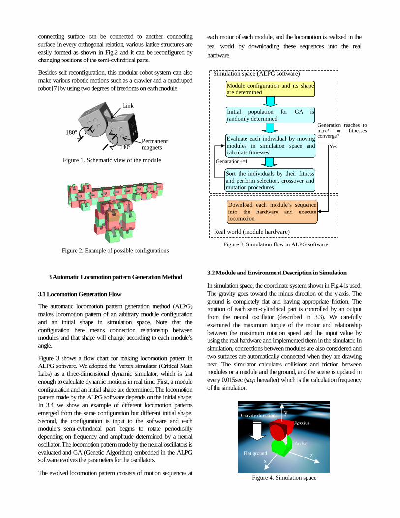
Figure 3 shows a flow chart for making locomotion pattern inALPG software. We adopted the Vortex simulator (Critical MathLabs) as a three-dimensional dynamic simulator, which is fastenough to calculate dynamic motions in real time. First, a moduleconfiguration and an initial shape are determined. The locomotionpattern made by the ALPG software depends on the initial shape.In 3.4 we show an example of different locomotion patternsemerged from the same configuration but different initial shape.Second, the configuration is input to the software and eachmodule’s semi-cylindrical part begins to rotate periodicallydepending on frequency and amplitude determined by a neuraloscillator. The locomotion pattern made by the neural oscillators isevaluated and GA (Genetic Algorithm) embedded in the ALPGsoftware evolves the parameters for the oscillators.
The evolved locomotion pattern consists of motion sequences at
each motor of each module, and the locomotion is realized in the
real world by downloading these sequences into the realhardware.
Module configuration and its shapeare determined
Initial population for GA israndomly determined
Evaluate each individual by movingmodules in simulation space andcalculate fitnesses
Sort the individuals by their fitnessand perform selection, crossover andmutation procedures
Download each module’s sequenceinto the hardware and executelocomotion
Simulation space (ALPG software)
Real world (module hardware)
Figure 3. Simulation flow in ALPG software
Generation reaches tomax? or fitnessesconverge?
Yes
Genaration+=1
3.2 Module and Environment Description in Simulation
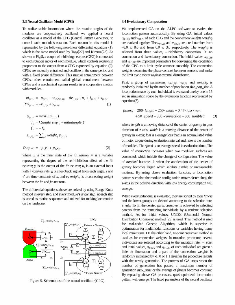
In simulation space, the coordinate system shown in Fig.4 is used.The gravity goes toward the minus direction of the y-axis. Theground is completely flat and having appropriate friction. Therotation of each semi-cylindrical part is controlled by an outputfrom the neural oscillator (described in 3.3). We carefullyexamined the maximum torque of the motor and relationshipbetween the maximum rotation speed and the input value byusing the real hardware and implemented them in the simulator. Insimulation, connections between modules are also considered andtwo surfaces are automatically connected when they are drawingnear. The simulator calculates collisions and friction betweenmodules or a module and the ground, and the scene is updated inevery 0.015sec (step hereafter) which is the calculation frequencyof the simulation.
xz
yGravity direction
Passive
Active
Figure 4. Simulation space
Flat ground
3.3 Neural Oscillator Model (CPG)
To realize stable locomotion where the rotation angles of themodules are cooperatively oscillated, we applied a neuraloscillator as a model of the CPG (Central Pattern Generator) tocontrol each module’s rotation. Each neuron in this model isrepresented by the following non-linear differential equations (1),which is the same model used by Taga[22] and Kimura[23]. Asshown in Fig.5, a couple of inhibiting neurons (CPG) is connectedto each rotation motor of each module, which controls rotation inproportion to the output from a CPG expressed by equation (2).CPGs are mutually entrained and oscillate in the same period andwith a fixed phase difference. This mutual entrainment betweenCPGs, other entrainment called global entrainment betweenCPGs and a mechanical system results in a cooperative motionwith modules.
)2(
)][(
),0max(
)1('
2211
}2,1{1}2,1{
12
1
}2,1{}2,1{
}2,1{}2,1{}2,1{
}2,1{}2,1{}2,1{}1,2{12}2,1{}2,1{
iii
j
n
j ijj
ii
iii
ii
iii
iieiiii
ypypOutput
yweights
ff
leinitialangstepanglekf
uy
yvv
sfuvywuu
+−=
=
−=−=
=
+−=
+++−−−=
∑ =
&
&
τβτ
where ui is the inner state of the ith neuron; vi is a variablerepresenting the degree of the self-inhibition effect of the ith
neuron; yi is the output of the ith neuron; ue is an external inputwith a constant rate; fi is a feedback signal from each angle. τ andτ’ are time constants of ui and vi; weightij is a connecting weightbetween the ith and jth neurons.
The differential equations above are solved by using Runge-Kuttamethod in every step, and every module’s angle[step] at each stepis stored as motion sequences and utilized for making locomotionon the hardware.
u1 v1β�
τ� τ’�
Extensor Neuron
u2 v2β�
τ� τ’�
Flexor Neuron
),0max( 11 ii uy =
),0max( 22 ii uy =
p1�
p2�
ue
w12
jnj ij yweight 11∑ =
jnj ij yweight 21∑ =
ue
f1i
f2i
Outputi
Passive
Active
CPGi
CPGi+1
CPGi
fi
fi+1
Figure 5. Schematics of the neural oscillator(CPG)
ue
ue
jnj ij yweight }2,1{1∑ =
jnj ij yweight }2,1{1∑ =
jnj ij yweight }2,1{1∑ =
|–
+
3.4 Evolutionary Computation
We implemented GA on the ALPG software to evolve thelocomotion pattern automatically. By using GA, initial valuesu0{1,2}i and v0{1,2}i of each CPG and the connection weights weightijare evolved together. The u0{1,2}i and v0{1,2}i are a real number from–8.0 to 8.0 and from 0.0 to 3.0 respectively. The weightij isselected from three values, –1:inhibitory connection, 0: noconnection and 1:excitatory connection. The initial values u0{1,2}i
and v0{1,2}i are important parameters for converging the oscillationof the CPG to a limit cycle attractor smoothly. The connectionweights determine the phase-contrast between neurons and makethe limit cycle robust against external disturbance.
First, a group of parameters, u0{1,2}i, v0{1,2}i and weightij, israndomly initialized by the number of population size, pop_size. Alocomotion made by each individual is evaluated one by one in 15sec in simulation space by the evaluation function represented byequation (3).
)3(30030050
/47.0250200
tumbledconnectionspeed
numlosswidthlengthfitness
⋅−⋅−⋅+⋅−⋅−⋅=
where length is a moving distance of the center of gravity in plusdirection of z-axis; width is a moving distance of the center ofgravity in x-axis; loss is a energy loss that is an accumulated valueof motor torque during evaluation interval and num is the numberof modules. The speed is an average speed in evaluation time. Thevalue of connection increases when two modules’ surfaces areconnected, which inhibits the change of configuration. The valueof tumbled becomes 1 when the acceleration of the center ofgravity becomes larger, which inhibits tumble or unreasonablemotions. By using above evaluation function, a locomotionpattern such that the module configuration moves faster along thez-axis in the positive direction with low energy consumption willemerge.
When every individual is evaluated, they are sorted by their fitnessand the lower groups are deleted according to the selection rate,s_rate. To fill the deleted parts, crossover is achieved by selectingparents from the remaining individuals by a roulette selectionmethod. As for initial values, UNDX (Unimodal NormalDistribution Crossover) method [25] is used. This method is usedfor real-coded Genetic Algorithm, which is superior inoptimization for multimodal functions or variables having manylocal minimums. On the other hand, N-point crossover method isused as for connection weights. In mutation procedure, severalindividuals are selected according to the mutation rate, m_rate,and initial values, u0{1,2}i and v0{1,2}i, of each individual are given alittle bit fluctuation and a part of the connection weights israndomly initialized by -1, 0 or 1. Hereafter the procedure restartswith the newly generation. The process of GA stops when thenumber of generation has passed a maximum number ofgeneration max_gene or the average of fitness becomes constant.By repeating above GA processes, quasi-optimized locomotionpattern will emerge. The fixed parameters of the neural oscillator

and GAare summarized in Table 1.
Table 1. Parameters for neural oscillator (N.O.) and GA
Parameters for N.O.ValueParameters for GAValue
τ 0.05 pop_size 150
τ’ 0.6 max_gene 150
β 1.5 s_rate 0.6
p1, p2 0.125 m_rate 0.05
k 8
w12 2.5
ue 8.5
(a) (b) (c)
(d) (e)
9 modules 9 modules 9 modules
6 modules 6 modules
Figure 6. Examples of tested configurations
(f)
4 modules
Figure 7. Obtained locomotion patterns, gait pattern(upper) and wave-like pattern (below)
3.5Application to Various Module Configurations
We applied ALPG method to various module configurationsshown in Fig.6. For every configuration stable locomotionpatterns were obtained. The obtained locomotion patterns of Fig.6(a) and (b) are shown in Fig.7. In spite of the configurations beingthe same, two different kinds of locomotion patterns wereobtained, one is a gait pattern and the other is a wave-like motion.This is caused by the difference of the initial shape.
Figure 8 shows the fitness curve of each configuration from Fig.6(a) to (f). It is found that the configuration (d) has the highestfitness value. On the flat grounds, it is considered that the crawlershape is more effective for moving faster since it can roll to move.
Figure 9 (a) shows the relationship between angle and angularvelocity for one of the motors involved in Fig.6 (a). Figure 9 (b)shows the transition of every motor’s angle of Fig.6 (a). It is foundthat every motors is oscillating with a constant frequency (about
1.2Hz), amplitude and phase-contrast, namely the locomotionpattern is stable. The needed time for making locomotion patternby ALPG software depends on the number of modules and thenumber of collisions at each step. It took about 6 hours by using2.53GHz Pentium 4 processor PC to evolve a stable walkingpattern for the 9-module configuration in Fig.6 (a).
-1000
0
1000
2000
3000
4000
5000
6000
0 10 20 30 40 50 60 70 80 -500
0
500
1000
1500
0 10 20 30 40 50 60 70 80
-1000
0
1000
2000
3000
4000
5000
6000
0 10 20 30 40 50 60 70 80 -5000
0
5000
10000
15000
0 10 20 30 40 50 60 70 80
-500
0
500
1000
1500
2000
2500
0 10 20 30 40 50 60 70 80 -1000
-500
0
500
1000
1500
2000
0 10 20 30 40 50 60 70 80
(a) (b)
(c) (d)
(e)(f)
Figure 8. Fitness vs. generation of various configurations shownin Fig.6
-3-2
-101
2
3
-0.8 -0.6 -0.4 -0.2 0 0.2 0.4 0.6 0.8
Angle (rad)
Ang
ular
velo
city
(rad
/s)
-1.5
-1
-0.5
0
0.5
1
1.5
7.49
7.97
8.45
8.93
9.41
9.89
10.4
10.8
11.3
11.8
12.3
12.8
13.2
13.7
14.2
14.7
Time (sec)
Ang
le(r
ad)
Figure 9. (a) Relationship between angle and angularvelocity for one of the motors involved in Fig.6 (a). (b)Transition of every motor’s angle in Fig.6 (a).
(a)
(b)
4 Hardware Experiments
4.1 Specifications of M-TRAN2 Module
We have developed twenty M-TRAN2 modules shown in Fig.10.There are two semi-cylindrical parts called a passive part and anactive part. The passive part has four permanent magnets (S poleoutside) on each of three surfaces. On the same surface, electrodesare placed symmetrically for power supply (VCC, GND), globalcommunication (RS-485) and local communication. Inside thepassive part, there are circuit boards including a microprocessor

(Neuron chip, TMPN3120FE5M, Echelon Corporation) forglobal inter-module communication and a microprocessor(PIC16F873, Microchip Technology, Inc.) for localcommunication. A power supply circuit and a battery are alsoembedded as shown in Fig.11. Power for the module is suppliedby an internal battery or by connecting wires from outside to anyof surfaces of the modules. In the experiments that follows weused the internal battery and no tethers were attached.
Inside the active part, there are connecting plates that will rise tothe surface by the attractive force of the magnets and connects twosurfaces electrically and mechanically. Two surfaces are alsodetached automatically by heating and lengthening shape memoryalloy coils by small light bulbs as shown in Fig.11. There is also amicroprocessor (PIC16F873) for controlling detachment and localcommunication with other modules.
Inside the link, there are two geared motors and their controlcircuit board that includes a microprocessor (PIC16F877) intowhich we implemented a PID position control program. Themotion sequence of each module made by the ALPG software isrealized by a trajectory control using this PID position control.
Specifications of M-TRAN2 module are summarized in Table 2.More details on mechanical and electrical design of M-TRAN2module are available in [26].
ActivePassive
Link
GND VCC (8V)
GlobalCommunication(RS-485)
Permanentmganet (S)
Localcommunication
Geared motor
Figure 10. M-TRAN2 module
Power supplycircuit
Main-CPU Connetingplate
Accelerationsensor
Neuronchip
PIC-P
Li-ion battery
PIC-A
Lightbulb
Permanentmagnet (N)
SMA coil
Non-linearspring
Figure 11. Inner structure of the module
4.2 Experimental Setup
Figure 12 shows the experimental setup and the internalcommunication system of the modules. First, the motion sequenceof each module made by the ALPG software is downloaded byusing global communication line between host PC and modulesand it is stored in Main-CPU RAM of each module. After the
download is completed, synchronization between modules isachieved by host PC and the cable is disconnected. In every 60msec each module’s Main-CPU sends the angle datum for eachstep to the microprocessor (PIC-M) in link and the locomotion ofthe modules is thereby realized in a cooperative manner.
Global communication (39kbps)
ALPG software on host PC
Local communication (4800bps)
Main-CPU(Neuron Chip)
PIC-APIC-MPIC-P
Transceiver (RS-485)
Local serial bus (4800bps)
Module
Main-CPU(Neuron Chip)
PIC-MPIC-P
Transceiver (R
Local serial b
M
Uhip)
PIC-AIC-M
ver (RS-485)
serial bus (4800bps)
Module
Figure 12. Experimental setup and communication system
4.3 Experiments on Locomotion
We have performed experiments on locomotion of all theconfigurations shown in Fig.6. As shown in Fig.13, all thelocomotion but Fig.6 (d) are successfully realized by realhardware. The moving speeds of locomotion in hardwareexperiments and in simulations are shown in Table 3. This provesthe validity of the simulation and the implemented model. As forthe configuration of Fig.6 (d), the chain was broken by a moduledetachment and we stopped the experiment. One of the reasonsfor the failure is that synchronization between modules was not
Table 2. Specifications of a M-TRAN2 module
Item ValueDimensionWeightCPUGlobal communicationLocal communicationPower supply (wired)Power supply (battery)Max. torque of each axisMax. rotation speedConnecting forceBatteryTotal power dissipationSensor
60x120x60mm0.4kg (including battery)Neuron chip and three PICsLonWorks, 39kbps4,800 bpsDC 8V~20VDC 3.8V19.8 kg cm (rating)0.5π rad/sec83 NLi-ion (3.8V, 700mAh)0.4W(8V)Acceleration sensor (3 axes)
Table 3. Comparison of the speed in hardware experimentsand in simulation
Hardware experiments Simulation(a)(b)(c)(d)(e)(f)
20 cm/sec4.5 cm/sec11cm/secN/A6.0 cm/sec6.0 cm/sec
23 cm/sec6.8 cm/sec19 cm/sec49.3 cm/sec7.9 cm/sec6.7 cm/sec
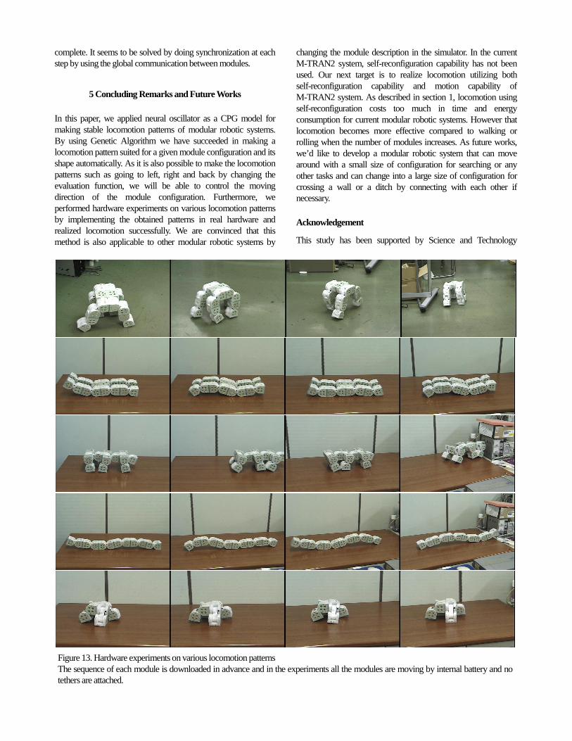
complete. It seems to be solved by doing synchronization at eachstep by using the global communication between modules.
5 Concluding Remarks and Future Works
In this paper, we applied neural oscillator as a CPG model formaking stable locomotion patterns of modular robotic systems.By using Genetic Algorithm we have succeeded in making alocomotion pattern suited for a given module configuration and itsshape automatically. As it is also possible to make the locomotionpatterns such as going to left, right and back by changing theevaluation function, we will be able to control the movingdirection of the module configuration. Furthermore, weperformed hardware experiments on various locomotion patternsby implementing the obtained patterns in real hardware andrealized locomotion successfully. We are convinced that thismethod is also applicable to other modular robotic systems by
changing the module description in the simulator. In the currentM-TRAN2 system, self-reconfiguration capability has not beenused. Our next target is to realize locomotion utilizing bothself-reconfiguration capability and motion capability ofM-TRAN2 system. As described in section 1, locomotion usingself-reconfiguration costs too much in time and energyconsumption for current modular robotic systems. However thatlocomotion becomes more effective compared to walking orrolling when the number of modules increases. As future works,we’d like to develop a modular robotic system that can movearound with a small size of configuration for searching or anyother tasks and can change into a large size of configuration forcrossing a wall or a ditch by connecting with each other ifnecessary.
Acknowledgement
This study has been supported by Science and Technology
Figure 13. Hardware experiments on various locomotion patternsThe sequence of each module is downloaded in advance and in the experiments all the modules are moving by internal battery and notethers are attached.�

Research Grant Program for Young Researchers with a Termfrom Ministry of Education, Culture, Sports, Science andTechnology (MEXT) of Japan.
As for neural oscillator (CPG) and its implementation we havebeen advised by Dr. Sooyol Ok at Communications ResearchLaboratory, Information and Network Systems Division,Keihanna Human Info-Communications Research Center, ImageGroup, Japan.
References[1] Y.Kawauchi, M.Inaba and T.Fukuda, A study on cellular
robotic system (A realization of robotic system capable ofadaption, self-organization, and self-evolution), RSJ, vol.12,116/132 (1994), in Japanese.
[2] G.S.Chirikjian, et al., Evaluating Efficiency ofSelf-Reconfiguration in a Class of Modular Robots,J.Robotic Systems, 12-5, 317/338 (1995).
[3] S.Murata, et al., Self-assembling machine, Proc. IEEEICRA, 441/448 (1994).
[4] S.Murata, et al., A 3-D self-reconfigurable structure, Proc.IEEE ICRA, 432/439 (1998).
[5] E.Yoshida, et al., Micro self-reconfigurable robotic systemusing shape memory alloy, DARS2000, 145/154 (2000).
[6] S.Murata, et al., Hardware Design of Modular RoboticSystem, Proc. IEEE IROS, 2210/2217 (2000).
[7] A.Kamimura, et al., Self-reconfigurable Modular Robot –Experiment on reconfiguration and locomotion, Proc. 2001IEEE/RSJ Int. Conf. on Intelligent Robots and Systems(IROS2001), 606–612, 2001.
[8] K.Hosokawa, et al, Self-Organizing Collective Robots withMorphogenesis in a Vertical Place, Proc. IEEE ICRA,2858/2863 (1998).
[9] D.Rus and M.Vona, A basis for self-reconfigurable robotsusing crystal modules, Proc. IEEE IROS, 2194/2202(2000).
[10] K.Kotay, et al., The self-reconfigurable robotic molecule,Proc. IEEE ICRA, 424/431 (1998).
[11] C.Ünsal, H.Kiliccote and K.Kohsla, I(CES)-cubes; amodular self-reconfigurable bipartite robotic system, Proc.SPIE, vol.3839, 258/269 (1999).
[12] A.Castano and P.Will, Mechanical design of a module forreconfigurable robots, Proc. IEEE IROS, 2203/2209 (2000).
[13] M.Yim, New Locomotion Gaits, Proc. IEEE ICRA,2508/2514 (1994).
[14] A.Casal and M.Yim, Self-reconfigurable planning for aclass of modular robot, Proc. SPIE, vol.3839, 246/257(1999).
[15] E.Yoshida, et al., Adistributed method for reconfiguration of3-D homogeneous structure, Advanced Robotics, 13-4,363/380 (1999).
[16] K.Tomita, et al., Self-assembly and self-repair method fordistributed mechanical system, IEEE Trans. on RoboticsandAutomation, 15-6, 1035/1045 (1999).
[17] K.Kotay and D.Rus, Motion synthesis for theself-reconfigurable molecule, Proc.1998 IEEE/RSJ Int.Conf. on Intelligent Robots and Systems, 843/851 (1998).
[18] C.Ünsal, et al., A modular self-reconfigurable bipartiterobotic system: implementation and motion planning,Autonomous Robots, 10-1, 23/40 (2001).
[19] Z.Butler, et al., Generic Decentralized Control for a Class ofSelf-Recon¯ gurable Robots, Proc. IEEE ICRA, 809/816(2002).
[20] K.C.Prevas, et al., A Hierarchical Motion Planning Strategyfor a Uniform Self-Reconfigurable Modular RoboticSystem, Proc. IEEE ICRA, 787/792 (2002).
[21] K.Matsuoka, Mechanisms of frequency and pattern controlin the neural rhythm generators, Biolog. Cybern., 56,345/353 (1987).
[22] G.Taga, A model of the neuro-musculo-skeletal system forhuman locomotion II – real-time adaptability under variousconstraints, Biolog. Cybern., 73, 113/121 (1995).
[23] H.Kimura, et al., Realization of dynamic walking andrunning of the quadruped using neural oscillator,Autonomous Robots, 7-3, 247/258 (1999).
[24] K.Hase, et al., Development of three-dimensionalwhole-body musculoskeletal model for various motionanalyses, JSME Int J C 40, 25/32 (1997).
[25] I.Ono and S. Kobayashi, A Real-coded Genetic Algorithmfor Function Optimization Using Unimodal NormalDistribution Crossover, Proc. 7th ICGA, 246/253 (1997).
[26] H.Kurokawa, et al., Self-Reconfigurable Modular Robot(M-TRAN) and its Motion Design, Proc. ICARCV 2002(will appear).