chapter 18 two-port circuits - 清華大學電機系 …sdyang/courses/circuits/ch18_std.pdf ·...
TRANSCRIPT
1
Chapter 18 Two-Port Circuits
18.1 The Terminal Equations18.2 The Two-Port Parameters18.3 Analysis of the Terminated Two-Port
Circuit 18.4 Interconnected Two-Port Circuits
2
Motivation
Thévenin and Norton equivalent circuits are used in representing the contribution of a circuit to one specific pair of terminals.
Usually, a signal is fed into one pair of terminals (input port), processed by the system, then extracted at a second pair of terminals (output port). It would be convenient to relate the v/i at one port to the v/i at the other port without knowing the element values and how they are connected inside the “black box”.
3
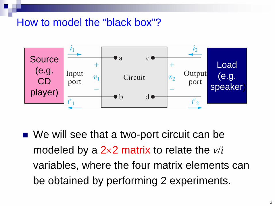
How to model the “black box”?
We will see that a two-port circuit can be modeled by a 22 matrix to relate the v/i variables, where the four matrix elements can be obtained by performing 2 experiments.
Source (e.g. CD
player)
Load (e.g.
speaker)
4
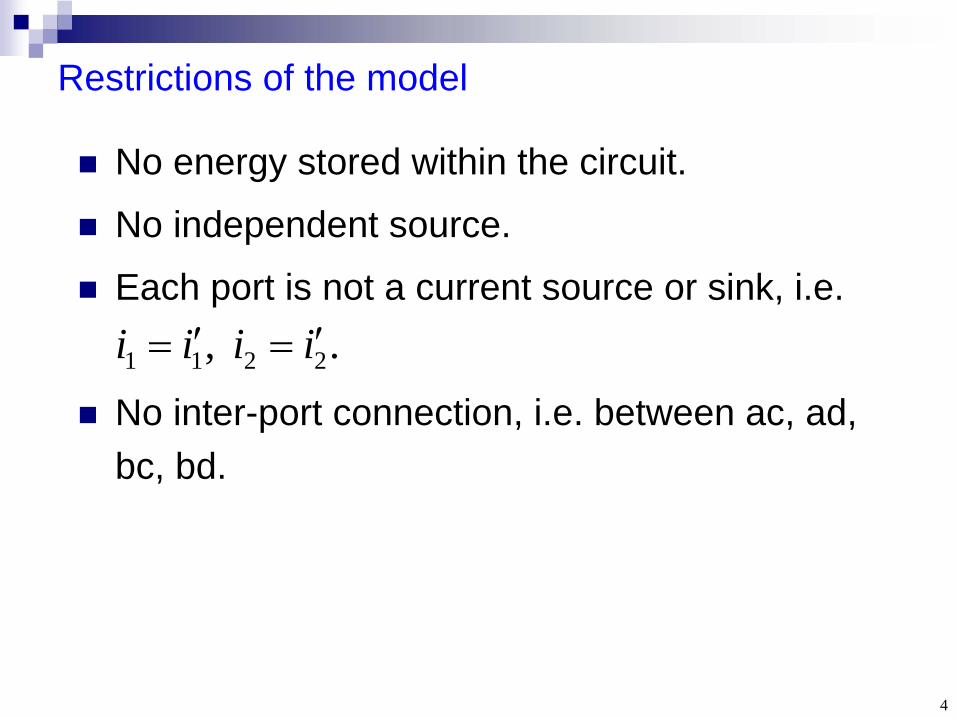
Restrictions of the model
No energy stored within the circuit.
No independent source.
Each port is not a current source or sink, i.e.
No inter-port connection, i.e. between ac, ad, bc, bd.
. , 2211 iiii
5
Key points
How to calculate the 6 possible 22 matrices of a two-port circuit?
How to find the 4 simultaneous equations in solving a terminated two-port circuit?
How to find the total 22 matrix of a circuit consisting of interconnected two-port circuits?
6
Section 18.1 The Terminal Equations
7
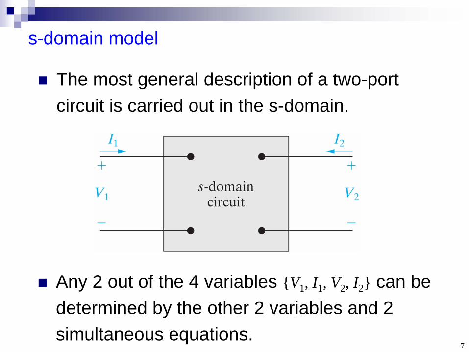
s-domain model
The most general description of a two-port circuit is carried out in the s-domain.
Any 2 out of the 4 variables {V1 , I1 , V2 , I2 } can be determined by the other 2 variables and 2 simultaneous equations.
8
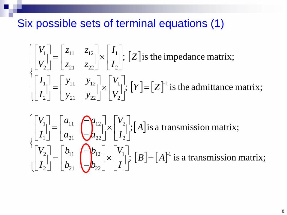
Six possible sets of terminal equations (1)
matrix; admittance theis ;
matrix; impedance theis ;
1-
2
1
2221
1211
2
1
2
1
2221
1211
2
1
ZYVV
yyyy
II
ZII
zzzz
VV
matrix; siona transmis is ;
matrix; siona transmis is ;
1-
1
1
2221
1211
2
2
2
2
2221
1211
1
1
ABIV
bbbb
IV
AIV
aaaa
IV
9
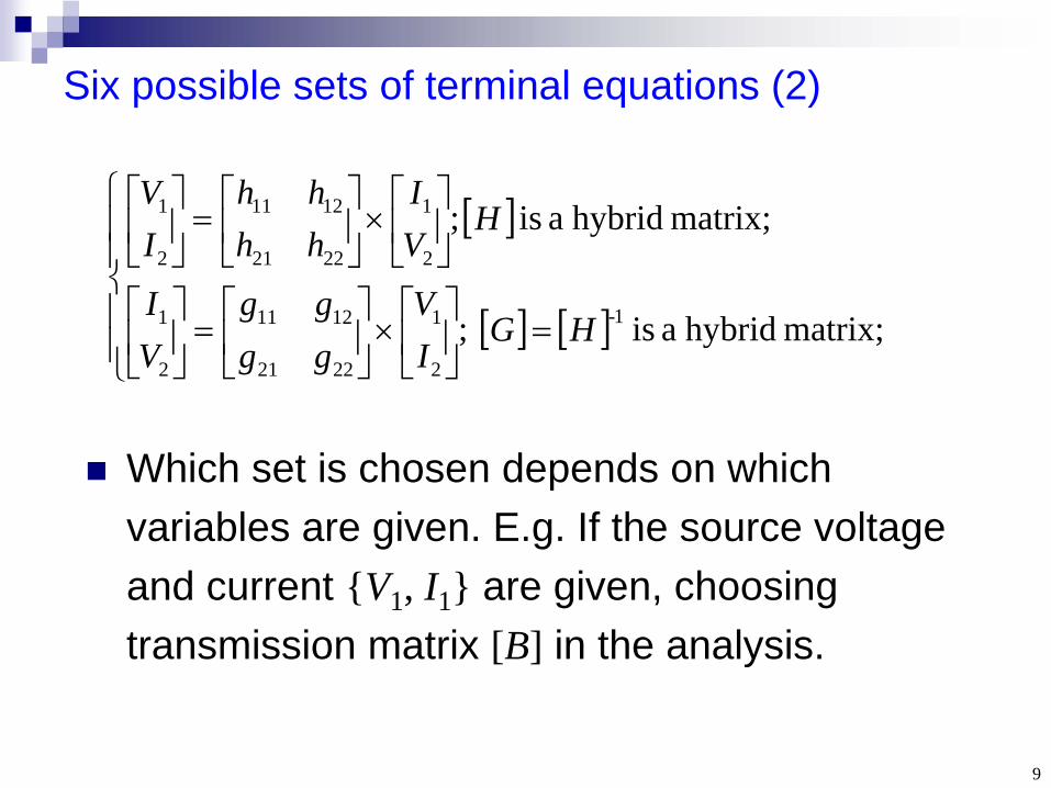
Six possible sets of terminal equations (2)
matrix; hybrida is ;
matrix; hybrida is ;
1-
2
1
2221
1211
2
1
2
1
2221
1211
2
1
HGIV
gggg
VI
HVI
hhhh
IV
Which set is chosen depends on which variables are given. E.g. If the source voltage and current {V1 , I1 } are given, choosing transmission matrix [B] in the analysis.

10
Section 18.2 The Two-Port Parameters
1. Calculation of matrix [Z]2. Relations among 6 matrixes

11
Example 18.1: Finding [Z] (1)
Q: Find the impedance matrix [Z] for a given resistive circuit (not a “black box”):
By definition, z11 = (V1 /I1 ) when I2 =0, i.e. the input impedance when port 2 is open. z11 = (20 )//(20 )=10 .
2
1
2221
1211
2
1
II
zzzz
VV
12
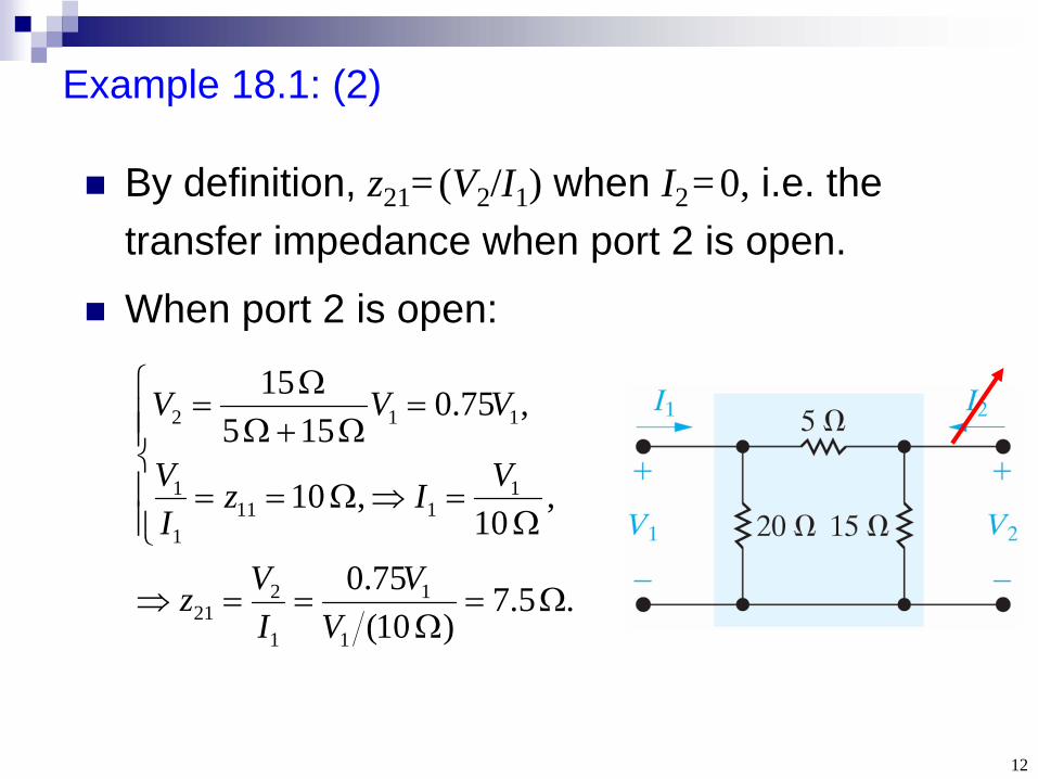
Example 18.1: (2)
By definition, z21 = (V2 /I1 ) when I2 =0, i.e. the transfer impedance when port 2 is open.
When port 2 is open:
. 5.7) 10(
75.0
, 10
, 10
,75.0 15 5
15
1
1
1
221
1111
1
1
112
VV
IVz
VIzIV
VVV
13
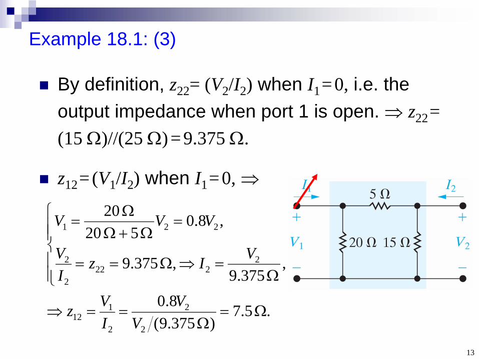
. 5.7) 375.9(
8.0
, 375.9
, 375.9
,8.0 5 02
02
2
2
2
112
2222
2
2
221
VV
IVz
VIzIV
VVV
Example 18.1: (3)
By definition, z22 = (V2 /I2 ) when I1 =0, i.e. the output impedance when port 1 is open. z22 = (15 )//(25 ) =9.375 .
z12 = (V1 /I2 ) when I1 =0,
14
Comments
When the circuit is well known, calculation of [Z] by circuit analysis methods shows the physical meaning of each matrix element.
When the circuit is a “black box”, we can perform 2 test experiments to get [Z]: (1) Open port 2, apply a current I1 to port 1, measure the input voltage V1 and output voltage V2 . (2) Open port 1, apply a current I2 to port 2, measure the terminal voltages V1 and V2 .
15
Relations among the 6 matrixes
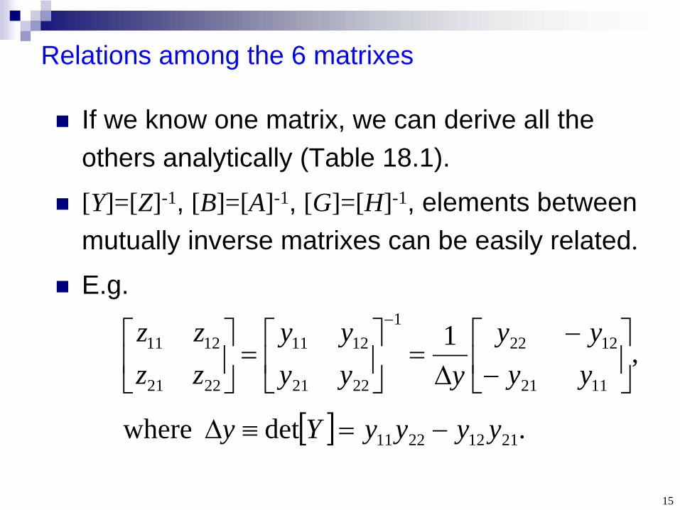
If we know one matrix, we can derive all the others analytically (Table 18.1).
[Y]=[Z]-1, [B]=[A]-1, [G]=[H]-1, elements between mutually inverse matrixes can be easily related.
E.g.
.det where
,1
21122211
1121
12221
2221
1211
2221
1211
yyyyYy
yyyy
yyyyy
zzzz
16
Represent [Z] by elements of [A] (1)
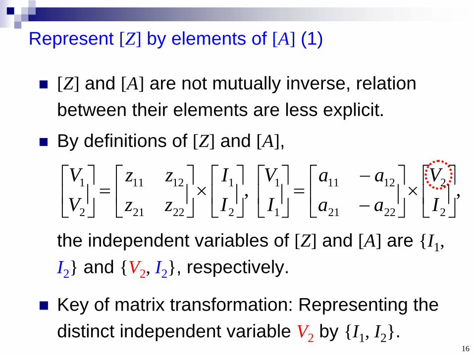
[Z] and [A] are not mutually inverse, relation between their elements are less explicit.
By definitions of [Z] and [A],
the independent variables of [Z] and [A] are {I1 , I2 } and {V2 , I2 }, respectively.
Key of matrix transformation: Representing the distinct independent variable V2 by {I1 , I2 }.
, ,2
2
2221
1211
1
1
2
1
2221
1211
2
1
IV
aaaa
IV
II
zzzz
VV
17
Represent [Z] by elements of [A] (2)
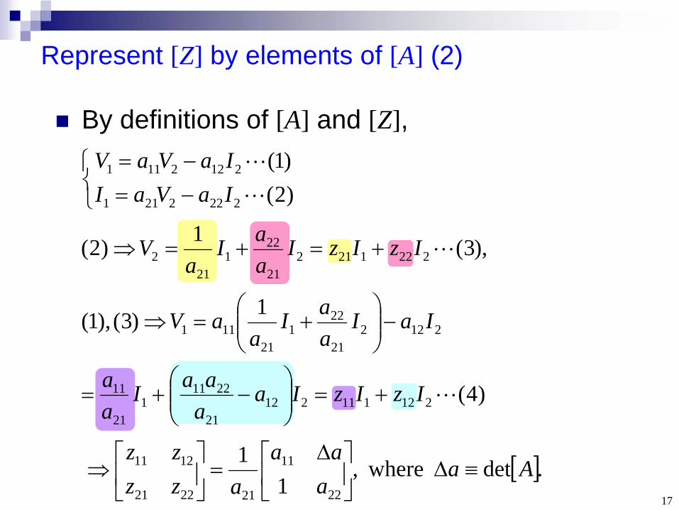
By definitions of [A] and [Z],
)2()1(
2222211
2122111
IaVaIIaVaV
.det where,1
122
11
212221
1211 Aaa
aaazz
zz
),3(1)2( 222121221
221
212 IzIzI
aaI
aV
)4(
1)3(),1(
21211121221
22111
21
11
212221
221
21111
IzIzIaaaaI
aa
IaIaaI
aaV
18
Section 18.3 Analysis of the Terminated Two-Port Circuit
1. Analysis in terms of [Z]2. Analysis in terms of [T][Z]
19
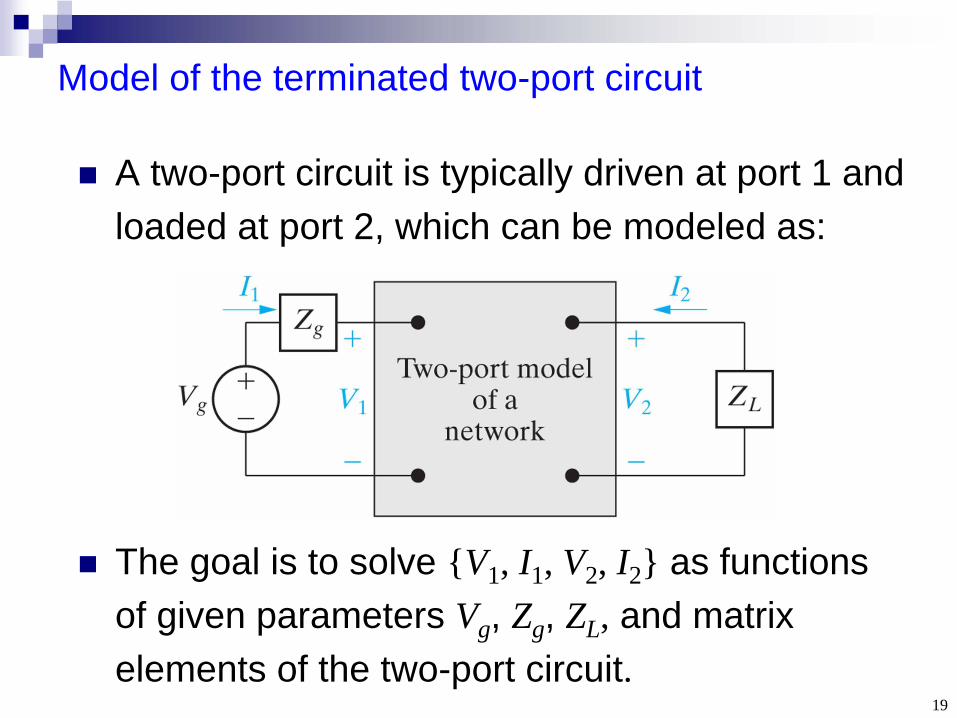
Model of the terminated two-port circuit
A two-port circuit is typically driven at port 1 and loaded at port 2, which can be modeled as:
The goal is to solve {V1 , I1 , V2 , I2 } as functions of given parameters Vg , Zg , ZL , and matrix elements of the two-port circuit.
20
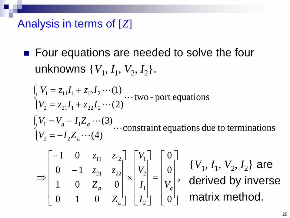
Analysis in terms of [Z]
Four equations are needed to solve the four unknowns {V1 , I1 , V2 , I2 }.
ons terminati todue equations constraint)4(
)3(
equationsport -two)2()1(
22
11
2221212
2121111
L
gg
ZIVZIVV
IzIzVIzIzV
,
0
00
010001
1001
2
1
2
1
2221
1211
g
L
g VIIVV
ZZ
zzzz
{V1 , I1 , V2 , I2 } are derived by inverse matrix method.
21
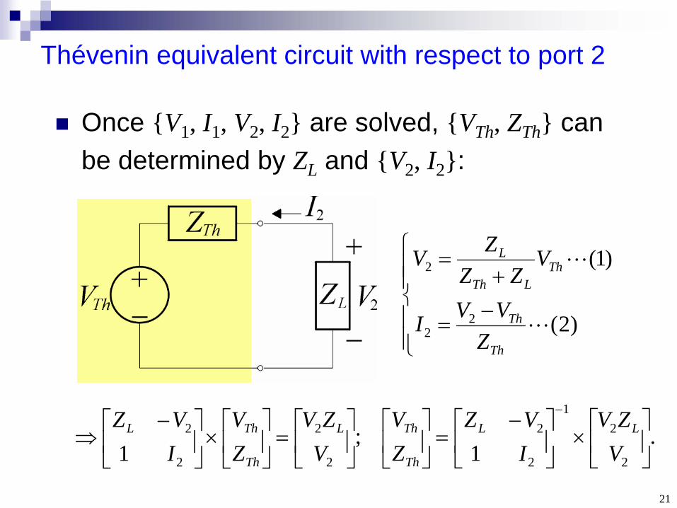
Thévenin equivalent circuit with respect to port 2
Once {V1 , I1 , V2 , I2 } are solved, {VTh , ZTh } can be determined by ZL and {V2 , I2 }:
)2(
)1(
22
2
Th
Th
ThLTh
L
ZVVI
VZZ
ZV
.1
;1 2
21
2
2
2
2
2
2
VZV
IVZ
ZV
VZV
ZV
IVZ LL
Th
ThL
Th
ThL
22
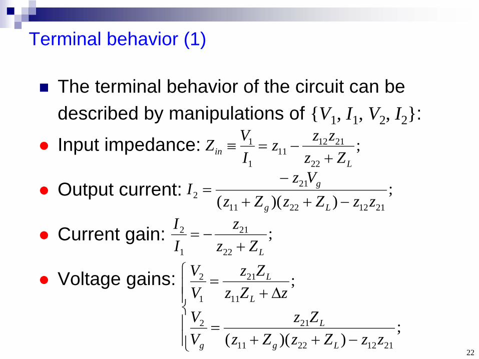
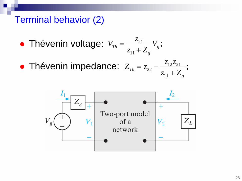
Terminal behavior (1)
The terminal behavior of the circuit can be described by manipulations of {V1 , I1 , V2 , I2 }:
Input impedance:
Output current:
Current gain:
Voltage gains:
;22
211211
1
1
Lin Zz
zzzIVZ
;))(( 21122211
212 zzZzZz
VzI
Lg
g
;22
21
1
2
LZzz
II
;))((
;
21122211
212
11
21
1
2
zzZzZzZz
VV
zZzZz
VV
Lg
L
g
L
L
23
Terminal behavior (2)
Thévenin voltage:
Thévenin impedance:
;11
21g
gTh V
ZzzV
;11
211222
gTh Zz
zzzZ
24
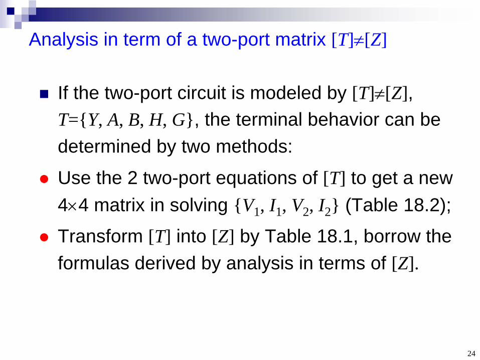
Analysis in term of a two-port matrix [T][Z]
If the two-port circuit is modeled by [T][Z], T={Y, A, B, H, G}, the terminal behavior can be determined by two methods:
Use the 2 two-port equations of [T] to get a new 44 matrix in solving {V1 , I1 , V2 , I2 } (Table 18.2);
Transform [T] into [Z] by Table 18.1, borrow the formulas derived by analysis in terms of [Z].
25
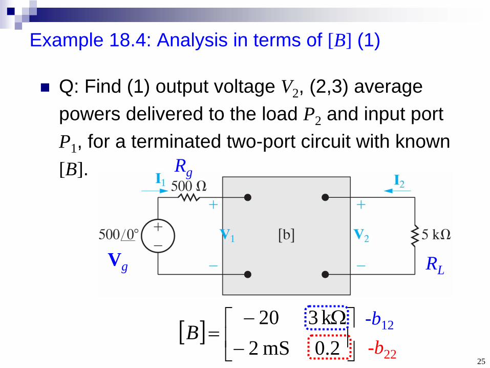
Example 18.4: Analysis in terms of [B] (1)
Q: Find (1) output voltage V2 , (2,3) average powers delivered to the load P2 and input port P1 , for a terminated two-port circuit with known [B].
2.0mS 2k 320
B-b12
-b22
RLVg
Rg
26
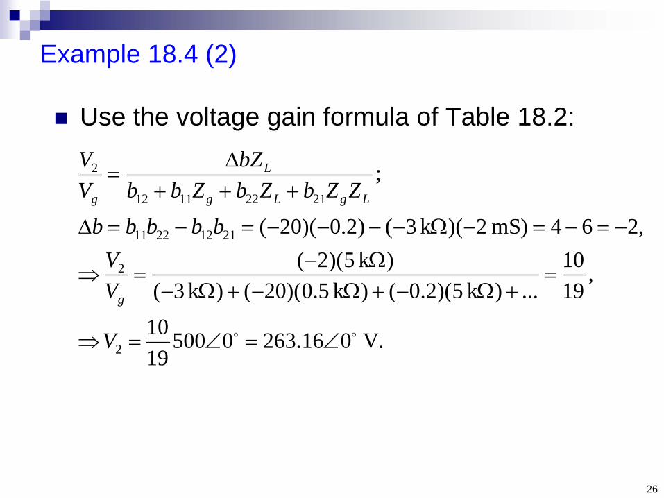
Example 18.4 (2)
Use the voltage gain formula of Table 18.2:
.V 016.26305001910
,1910
...)k 5)(2.0()k 5.0)(20()k 3()k 5)(2(
,264)mS 2)(k 3()2.0)(20(
;
2
2
21122211
21221112
2
V
VV
bbbbbZZbZbZbb
bZVV
g
LgLg
L
g
27
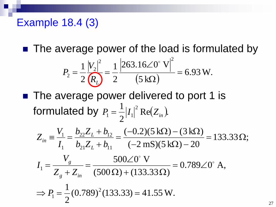
Example 18.4 (3)
The average power of the load is formulated by
.W 93.6k 5
V 016.26321
21
222
2
LRV
P
The average power delivered to port 1 is formulated by .Re
21 2
11 inZIP
W. 55.41)33.133()789.0(21
A, 0789.0) 33.133() 500(
V 0500
; 33.13320)k 5)(mS 2(
)k 3()k 5)(2.0(
21
1
1121
1222
1
1
P
ZZV
I
bZbbZb
IVZ
ing
g
L
Lin

28
Section 18.4 Interconnected Two-Port Circuits

29
Why interconnected?
Design of a large system is simplified by first designing subsections (usually modeled by two-port circuits), then interconnecting these units to complete the system.
30
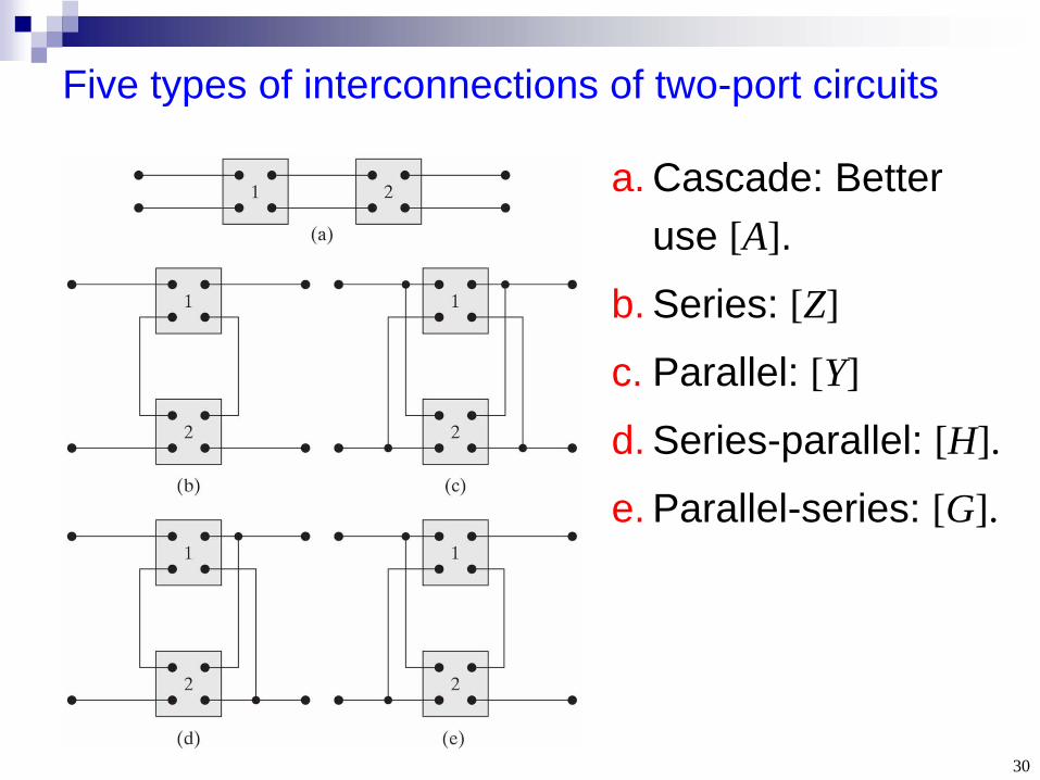
Five types of interconnections of two-port circuits
a. Cascade: Better use [A].
b. Series: [Z]
c. Parallel: [Y]
d. Series-parallel: [H].
e. Parallel-series: [G].
31
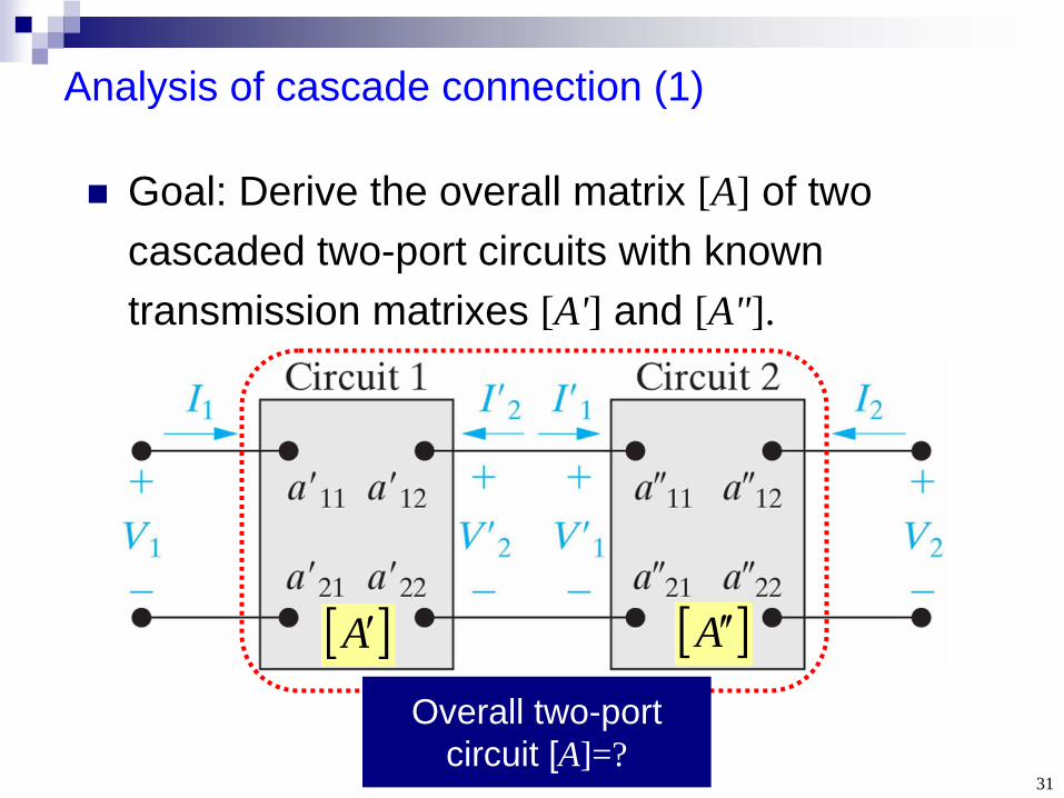
Analysis of cascade connection (1)
Goal: Derive the overall matrix [A] of two cascaded two-port circuits with known transmission matrixes [A'] and [A"].
A A
Overall two-port circuit [A]=?
)2(
,
2
2
2
2
2221
1211
1
1
2
2
2221
1211
2
2
1
1
I
VA
I
V
aa
aa
I
V
I
V
aa
aa
I
VA
I
V
32
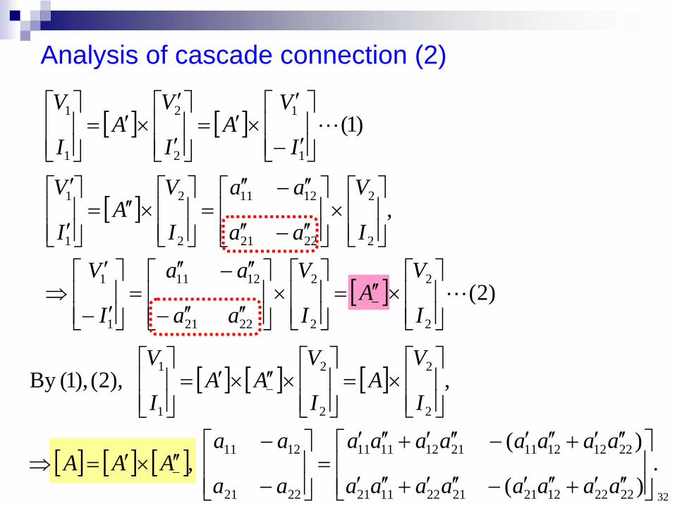
Analysis of cascade connection (2)
)1(1
1
2
2
1
1
I
VA
I
VA
I
V
.)(
)( ,
, ),2(),1(By
2222122121221121
2212121121121111
2221
1211
2
2
2
2
1
1
aaaaaaaa
aaaaaaaa
aa
aaAAA
I
VA
I
VAA
I
V
33
Key points
How to calculate the 6 possible 22 matrices of a two-port circuit?
How to find the 4 simultaneous equations in solving a terminated two-port circuit?
How to find the total 22 matrix of a circuit consisting of interconnected two-port circuits?

34
Practical Perspective Audio Amplifier
35
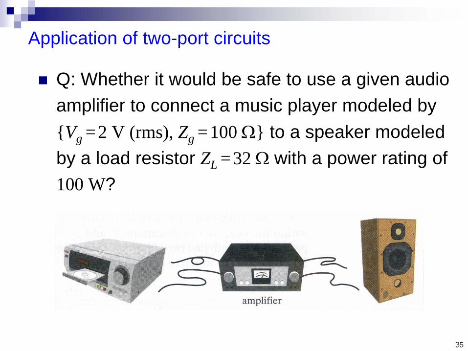
Application of two-port circuits
Q: Whether it would be safe to use a given audio amplifier to connect a music player modeled by {Vg =2 V (rms), Zg =100 } to a speaker modeled by a load resistor ZL =32
with a power rating of
100 W?
36
Find the [H] by 2 test experiments (1)
;2
1
2221
1211
2
1
V
I
hh
hh
I
V
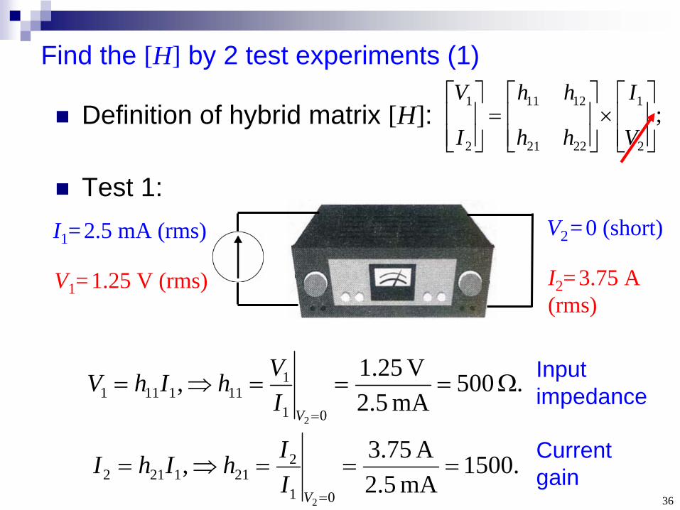
Definition of hybrid matrix [H]:
Test 1:I1 =2.5 mA (rms) V2 =0 (short)
. 500mA 5.2
V 25.1 ,01
1111111
2
VI
VhIhV
.1500mA 5.2
A 75.3 ,01
2211212
2
VI
IhIhI
V1 = 1.25 V (rms) I2 =3.75 A (rms)
Input impedance
Current gain
37
Find the [H] by 2 test experiments (2)
;2
1
2221
1211
2
1
V
I
hh
hh
I
V
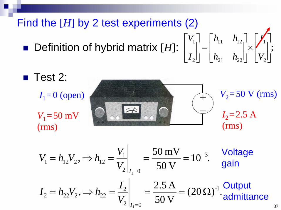
Definition of hybrid matrix [H]:
Test 2:I1 = 0 (open) V2 =50 V (rms)
.10V 05
mV 50 , 3
02
1122121
1
IV
VhVhV
.) 20(V 05A 5.2 , 1-
02
2222222
1
IV
IhVhI
V1 =50 mV (rms)
I2 =2.5 A (rms)
Voltage gain
Output admittance
38
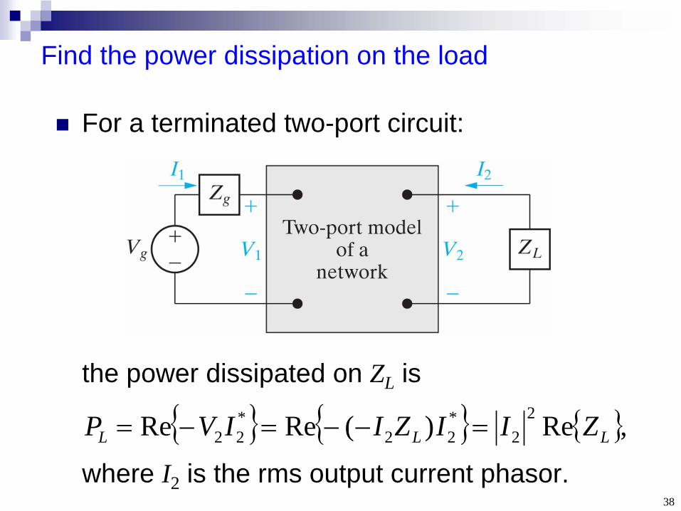
Find the power dissipation on the load
For a terminated two-port circuit:
,Re)(ReRe 22
*22
*22 LLL ZIIZIIVP
the power dissipated on ZL is
where I2 is the rms output current phasor.
39
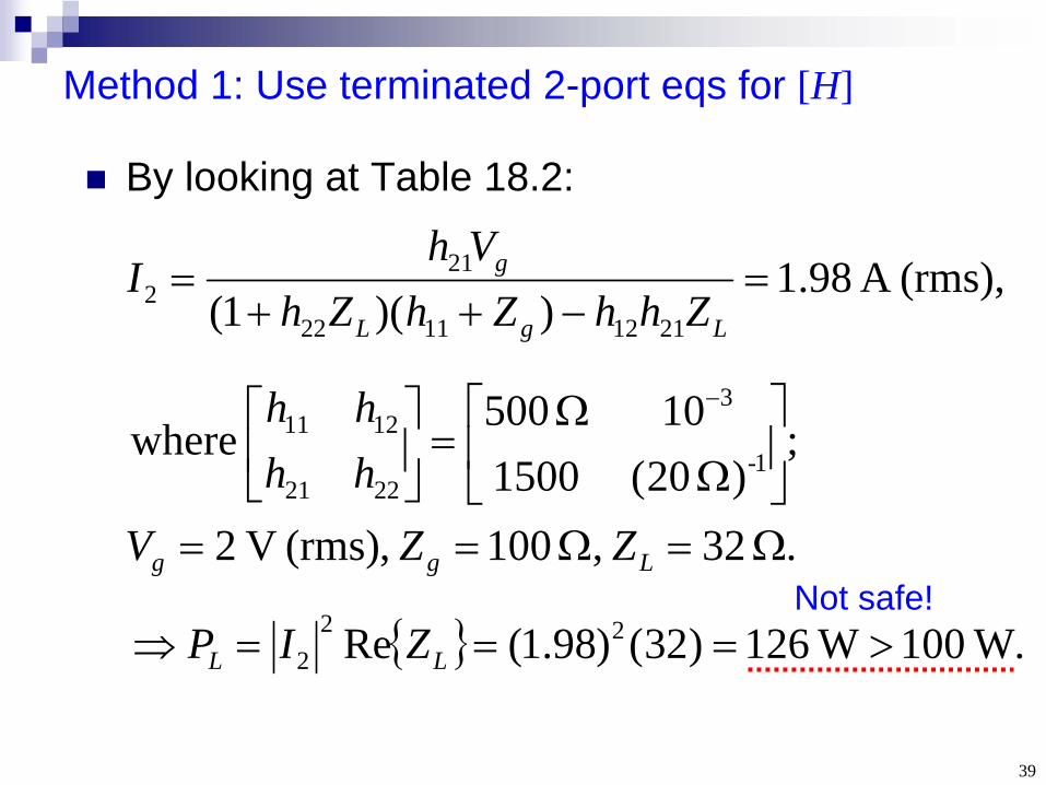
Method 1: Use terminated 2-port eqs for [H]
By looking at Table 18.2:
(rms), A 98.1))(1( 21121122
212
LgL
g
ZhhZhZhVh
I
. 32 , 100 ,(rms) V 2
;) 20(1500
10 500 where 1-
3
2221
1211
Lgg ZZV
hhhh
.W 100W 126)32()98.1(Re 222 LL ZIP
Not safe!
40
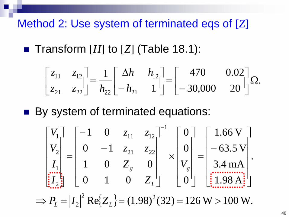
Method 2: Use system of terminated eqs of [Z]
Transform [H] to [Z] (Table 18.1):
.W 100W 126)32()98.1(Re 222 LL ZIP
. 20000,3002.0470
11
21
12
222221
1211
h
hhhzz
zz
.
A 98.1mA .43
V 63.5V 66.1
0
00
010001
1001 1
2221
1211
2
1
2
1
g
L
g VZ
Zzzzz
IIVV
By system of terminated equations: