clafer: unifying class and feature modeling
TRANSCRIPT

Software and Systems Modeling manuscript No.(will be inserted by the editor)
Clafer: Unifying Class and Feature Modeling
Kacper Bąk · Zinovy Diskin · Michał Antkiewicz · Krzysztof Czarnecki ·Andrzej Wąsowski
Received: date / Accepted: date
Abstract We present Clafer (class, feature, reference),a class modeling language with first-class support forfeature modeling. We designed Clafer as a concise nota-tion for meta-models, feature models, mixtures of meta-and feature models (such as components with options),and models that couple feature models and meta-modelsvia constraints (such as mapping feature configurationsto component configurations or model templates). Claferallows arranging models into multiple specialization andextension layers via constraints and inheritance. Weidentify several key mechanisms allowing a meta-modelinglanguage to express feature models concisely. Claferunifies basic modeling constructs, such as class, associa-tion, and property, into a single construct, called clafer.We provide the language with a formal semantics builtin a structurally-explicit way. The resulting semanticsexplains the meaning of hierarchical models wherebyproperties can be arbitrarily nested in the presence ofinheritance and feature modeling constructs. The se-mantics also enables building consistent automated rea-soning support for the language: to date, we imple-mented three reasoners for Clafer based on Alloy, Z3
Kacper BąkGSD Lab, University of Waterloo, CanadaE-mail: [email protected]
Zinovy DiskinGSD Lab, University of Waterloo, CanadaE-mail: [email protected]
Michał AntkiewiczGSD Lab, University of Waterloo, CanadaE-mail: [email protected]
Krzysztof CzarneckiGSD Lab, University of Waterloo, CanadaE-mail: [email protected]
Andrzej WąsowskiIT University of Copenhagen, DenmarkE-mail: [email protected]
SMT, and Choco3 CSP solvers. We show that Clafermeets its design objectives using examples and by com-paring to other languages.
Keywords Language Design · Feature Modeling ·OOM · Semantics · Unification
CR Subject Classification D.2.1 [Software Engi-neering]: Requirements/Specifications—languages
1 Introduction
Both feature and meta-modeling have been used inSoftware Product Line (SPL) engineering to model vari-ability. Feature models can be seen as tree-like menusof mostly Boolean, sometimes also numerical and tex-tual, configuration options, augmented with cross-treeconstraints [45]. These models are typically used toshow the variation of user-relevant characteristics ofproduct variants within a product line. In contrast,meta-models, usually represented as class models as ex-pressed using Meta Object Facility (MOF) [54], specifyconcepts representing more detailed aspects of prod-ucts; including behavioral and architectural aspects. Forexample, meta-models are often used to specify thecomponent and connector types of product line archi-tectures and the valid ways of connecting them. The na-ture of variability expressed by each type of models isdifferent: feature models capture selections from prede-fined choices within a fixed tree structure; meta-modelssupport making new structures by creating multiple in-stances of classes and connecting them via links.
Over the last decade, the distinction between fea-ture models and meta-models has been blurred in theliterature due to (i) feature modeling extensions, suchas cardinality-based feature modeling [21,6], (ii) propos-als to unify feature modeling notations into a useful

2 Kacper Bąk et al.
and widely applicable subset [58], and (iii) attemptsto express feature models as class models in the Uni-fied Modeling Language (UML) [16,23]. In fact, a num-ber of practitioners use UML-based representations tomodel variability [11]. A key driver behind some ofthese developments has been the desire to express bothconfiguration options and variability of component ar-chitecture instantiations in one notation [19,37,38,32].Cardinality-based feature modeling achieves this by ex-tending feature models toward class modeling by in-troducing multiple instantiation and references. It isincomplete, however, because it does not offer inheri-tance. Class modeling, which natively supports multipleinstantiation, references, and inheritance, enables fea-ture modeling by a stylized use of containment (UML’scomposition) and the profiling mechanisms of MOF orUML (e.g., as in [34]).
Both developments have notable drawbacks, how-ever. An important advantage of feature modeling asoriginally defined by Kang et al. [45] is its simplicity;several respondents to a recent survey confirmed thisview [46]. Extending feature modeling with multiple in-stantiation and references diminishes this advantage byintroducing additional complexity. Models that containsignificant amounts of multiply-instantiatable featuresand references can be hardly called feature models inthe original sense; they are more of class models ratherthan easy-to-use menus guiding configuration decisions.On the other hand, whereas the model parts requiringmultiple instantiation and references are naturally ex-pressed as class models, the parts that have feature-modeling nature cannot be expressed simply in classmodels, but rather clumsily simulated using compo-sition hierarchy and certain modeling patterns. Evenworse, such a solution requires inconvenient model refac-torings, while according to a recent survey [11], evolv-ability of variability models is one of the main chal-lenges faced by practitioners.
We present Clafer (class, feature, reference), a lan-guage that unifies feature and class modeling. It cannaturally express feature models, while allowing for fullclass modeling and relating both types of models. Clafersupports: (i) class-based meta-models, (ii) object mod-els, (iii) partial object models (with uncertainty), (iv) fea-ture models with attributes and multiple instantiation,(v) full and partial configurations of feature models,(vi) mixtures of meta- and feature models and modeltemplates [18], (vii) first-order logic constraints. Claferalso allows arranging models into multiple specializa-tion and extension layers via constraints and inheri-tance. On the other hand, by designing Clafer we wantedto create a language that builds upon as few conceptsas possible and that is easy to learn. The main princi-ple guiding our design was that “simple things (feature
models and simple constraints) should be natural andsimple while complex things (meta-models and complexconstraints) should be possible”.
In this paper, we present several contributions.1. We identified several key mechanisms allowing a meta-
modeling language to express feature models con-cisely; particularly, concept unification, instance com-position and type nesting, and default singleton mul-tiplicity.
2. We unify basic constructs of structural modeling:class, association, and property (which includes at-tribute, reference, and role), into a single construct,called clafer. Such a construct has the characteris-tics of a class (ability to nest and inherit propertiesand other classes in it), an association (ability tonavigate over it), and an attribute (ability to storesingle or multiple (set, bag) values of primitive typesin it).
3. Rich semantic capabilities are packed into very com-pact syntax that makes class models concise. If nec-essary, concrete uses of Clafer could introduce syn-tax to distinguish among the various interpretationsof clafers, such as features, classes, components, aswell as, any domain-specific concepts.
4. We provide a mathematical model of Clafer’s syn-tactical mechanism (meta-models and the overall ar-chitecture) using formal class diagrams [29], whichis a structural modeling formalism based on cate-gory theory and diagrammatic logic [31]. The for-malism has allowed us to define semantics conciselyby specifying mappings between artifacts and oper-ations over the artifacts and mappings. The struc-tures of the syntactic and semantic domains arealigned and made explicit rather than flattened andhidden in a multitude of first-order logic formulas.The main benefit of semantic unification is simplifi-
cation of analyses and tools that operate both on fea-ture and class models, and mappings between them.The language is supported by tools for model analy-ses including consistency checking, instantiation and in-stance completion [48,49], and single- and multi-objectiveoptimization [53]. Analyzes are performed by translat-ing Clafer models into the input language of the under-lying backend solvers (Alloy relational logic solver [40],Z3 Satisfiability Modulo Theories (SMT) solver [26],and Choco 3 Constraint Satisfaction Problems (CSP)and Constraint Programming (CP) solver) [44]. The re-sults of the analysis are translated back to Clafer. Wealso provide a web-based suite of tools for working withClafer models and the backend solvers [3,52].
In the industrial context, support for variability isneeded when modeling product-line architectures usingsuch standards as AUTOSAR [56], EAST-ADL [17],and SysML [35]. These standards do not require the
Clafer: Unifying Class and Feature Modeling 3
unification of feature and class modeling; however, theypoint to the need of having both feature and architec-tural models in a single, integrated system specification.In fact, the first level of an EAST-ADL specification isthe technical feature model and AUTOSAR defines afeature model interchange format [57] allowing for inte-gration of external feature modeling tools and supportfor adding variation points into AUTOSAR models.The thesis by Padilla Gaeta demonstrates techniquesfor adding variability to SysML models [33]. Further-more, formal reasoning, such as constraint checking andpropagation, over such integrated specifications is re-quired, which in turn, necessitates the integration ofthe modeling languages and the supporting reasoners.In contrast, by unifying feature and class models inClafer, we provide unified reasoning support for such in-tegrated system specifications. For example, the thesisby Murashkin demonstrates that Clafer can express andoptimize complex automotive electronic/electric archi-tectural models that span three abstraction levels of anarchitecture modeling standard EAST-ADL [51].
The paper is organized as follows. We introduce ourrunning example in Sect. 2. We define (i) the challengesof representing the example using either only class mod-eling or only feature modeling, (ii) the challenges ofmapping feature configurations to component and op-tion configurations, and (iii) a set of design objectivesfor Clafer in Sect. 3. We then present Clafer in Sect. 4and show that it naturally supports unified feature andclass modeling. Section 5 explains the semantic founda-tions of Clafer, and shows how it implements the uni-fication idea. Section 6 describes Clafer syntax designin more detail, and shows that a Clafer model is a hi-erarchical view on a formal class diagram. We evaluatethe language analytically in Sect. 7 and demonstratethat it satisfies the design objectives. We conclude inSect. 9, after having compared Clafer with related workin Sect. 8. Our work is supported with a set of appen-dices following the main body of the paper.
2 Modeling Variability in SPLs: An Example
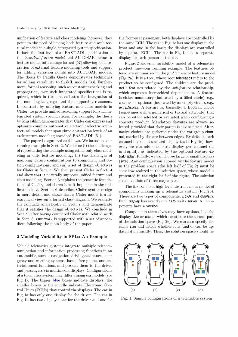
Vehicle telematics systems integrate multiple telecom-munication and information processing functions in anautomobile, such as navigation, driving assistance, emer-gency and warning systems, hands-free phone, and en-tertainment functions, and present them to the driverand passengers via multimedia displays. Configurationsof a telematics system may differ among car models (seeFig. 1). The bigger blue boxes indicate displays; thesmaller boxes in the middle indicate Electronic Con-trol Units (ECUs) that control the displays. The car inFig. 1a has only one display for the driver. The car inFig. 1b has two displays: one for the driver and one for
the front-seat passenger; both displays are controlled bythe same ECU. The car in Fig. 1c has one display in thefront and one in the back; the displays are controlledby separate ECUs. The car in Fig. 1d has a separatedisplay for each person in the car.
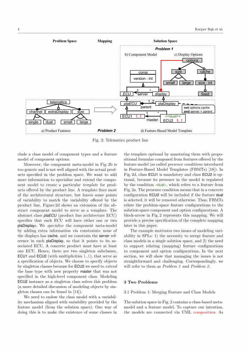
Figure 2 shows a variability model of a telematicsproduct line—our running example. The features of-fered are summarized in the problem-space feature model(Fig. 2a). It is a tree, whose root telematics refers to theproduct to be configured. The children are the prod-uct’s features related by the sub-feature relationship,which expresses hierarchical dependencies. A featureis either mandatory (indicated by a filled circle), e.g.,channel, or optional (indicated by an empty circle), e.g.,extraDisplay. A feature is, basically, a Boolean choice(sometimes with a numerical or textual attribute) thatcan be either selected or excluded when configuring aconcrete product. Mandatory features are always se-lected, provided that their parent is also selected. Alter-native choices are gathered under the xor-group chan-nel, marked by the arc between edges. By default, eachchannel has one associated display (as in Fig. 1c); how-ever, we can add one extra display per channel (asin Fig. 1d), as indicated by the optional feature ex-traDisplay. Finally, we can choose large or small displays(size). Any configuration allowed by the feature modelin the problem space (the left half of Fig. 2) must besomehow realized in the solution space, whose model ispresented in the right half of the figure. The solutionspace consists of three major parts.
The first one is a high-level abstract meta-model ofcomponents making up a telematics system (Fig. 2b).There are two types of components: ECUs and displays.Each display has exactly one ECU as its server. All com-ponents have a version.
Components themselves may have options, like thedisplay size or cache, which constitute the second partof the solution space (Fig. 2c). We can also specify thecache size and decide whether it is fixed or can be up-dated dynamically. Thus, the solution space should in-
(a) (b) (c) (d)
Fig. 1: Sample configurations of a telematics system
4 Kacper Bąk et al.
Fig. 2: Telematics product line
clude a class model of component types and a featuremodel of component options.
Moreover, the component meta-model in Fig. 2b istoo generic and is not well aligned with the actual prod-ucts specified in the problem space. We want to addmore information to specialize and extend the compo-nent model to create a particular template for prod-ucts offered by the product line. A template fixes mostof the architectural structure, but leaves some pointsof variability to match the variability offered by theproduct line. Figure 2d shows an extension of the ab-stract component model to serve as a template. Theabstract class plaECU (product line architecture ECU)specifies that each ECU will have either one or twoplaDisplays. We specialize the component meta-modelby adding extra information via constraints: none ofthe displays has cache, and we constrain the server ref-erence in each plaDisplay, so that it points to its as-sociated ECU. A concrete product must have at leastone ECU. Hence, there are two singleton subclasses,ECU1 and ECU2 (with multiplicities 1..1), that serve asa specification of objects. We choose to specify objectsby singleton classes because for ECU2 we need to extendthe base type with new property master that was notspecified in the high-level component class. ModelingECU2 instance as a singleton class solves this problem(a more detailed discussion of modeling objects by sin-gleton classes can be found in [14]).
We need to endow the class model with a variabil-ity mechanism aligned with variability provided by thefeature model (from the solution space). One way ofdoing this is to make the existence of some classes in
the template optional by annotating them with propo-sitional formulas composed from features offered by thefeature model (so called presence conditions introducedin Feature-Based Model Templates (FBMTs) [18]). InFig. 2d, class ECU1 is mandatory and class ECU2 is op-tional, because its presence in the model is regulatedby the condition «dual», which refers to a feature fromFig. 2a. The presence condition means that in a concreteconfiguration ECU2 will be included if the feature dualis selected; it will be removed otherwise. Thus, FBMTsrelate the problem-space feature configurations to thesolution-space component and option configurations. Ablock-arrow in Fig. 2 represents this mapping. We willprovide a precise specification of the complete mappinglater in this paper.
The example motivates two issues of modeling vari-ability in SPLs: 1) the necessity to merge feature andclass models in a single solution space, and 2) the needto support relating (mapping) feature configurationsto component and option configurations. In the nextsection, we will show that managing the issues is notstraightforward and challenging. Correspondingly, wewill refer to them as Problem 1 and Problem 2 .
3 Two Problems
3.1 Problem 1: Merging Feature and Class Models
The solution space in Fig. 2 contains a class-based meta-model and a feature model. To capture our intention,the models are connected via UML composition. As

Clafer: Unifying Class and Feature Modeling 5
Fig. 3: Cardinality-based feature model of components
the precise semantics of such notational mixture is notclear, this connection should be understood only infor-mally for now. Basically, we have two choices to modelcomponents and options in a single notation: either en-rich feature modeling to allow it to capture class mod-eling, or encode feature models as class models. We willconsider them in the two consecutive subsections.
3.1.1 Class Modeling via Feature Modeling
Figure 3 shows the part of the model which representscomponents. The model introduces a synthetic root fea-ture; display and ECU can be multiply instantiated (asindicated by the multiplicity *), but they cannot be ab-stract; and display has a server subfeature representinga reference to instances of ECU. Two subfeatures ver-sion are added to display and ECU to match the meta-model in Fig. 2b since feature models do not supportinheritance. Extending cardinality-based feature mod-eling with inheritance would bring the notation veryclose to class modeling, posing the question whetherclass modeling should not be used for the entire solu-tion space model instead. Furthermore, the semanticsof such an extended notation is unclear.
We may conclude that cardinality-based feature mod-eling blurs the distinction between feature modelingand class modeling. It encompasses mechanisms charac-teristic of class modeling, such as multiple instantiationand references, and could even be extended further to-ward class modeling, e.g., with inheritance; however,the result can hardly be called ‘feature modeling’ in itsclassical sense, as it clearly goes beyond the originalscope of feature modeling [45].
3.1.2 Feature Modeling via Class Modeling
Figure 4 shows only the display option model, as thecomponent model remains unchanged (as in Fig. 2b). A
Fig. 4: Meta-model of display options
(a) Iteration 1
(b) Iteration 2
Fig. 5: Evolved meta-model of display options
subfeature is either an attribute (if it has no other sub-features) or a class (if it has features) – we choose thesimplest suitable language construct. Subfeature rela-tionships are represented either as property nesting oras UML composition. Feature multiplicities correspondto property multiplicities. The xor-group is encoded byenumeration.
Representing a feature model as a UML class modelworks reasonably well for our small example; however,it does have several drawbacks:
1) Limited property nesting and model refactoring.The feature model shows fixed as a property of sizeby nesting. This intention is lost in the class model,in which fixed is a property of cache rather than size;particularly, if the attribute size was optional, the at-tribute fixed could exist even if size was eliminated. Tofix this drawback, we could add an Object ConstraintLanguage (OCL) [55] constraint expressing the depen-dency but hiding an important structural informationwithin constraints is not generally advisable.
A better solution would be to reify the attributesize as a class contained in cache as shown in Fig. 5a, inwhich the structural dependency is explicit. Note alsothat in some cases, reification of attributes would natu-

6 Kacper Bąk et al.
rally be modeled using subclassing rather than contain-ment. Suppose, for example, that we need to add anoptional property hd (high definition) to large displays.A natural way to do this is shown in Fig. 5b, which isagain a substantial refactoring of the initial class modelfrom Fig. 4. In contrast, adding the property hd to thefeature model in Fig. 2a amounts to plain nesting thefeature hd under the feature large.
These examples show a general drawback of ordi-nary class modeling in the context of gradual modeldevelopment. Modeling properties by attributes is com-pact, but disallows further nesting. On the other hand,modeling properties by classes leads to bulky models;even worse, there are several ways of such modeling,which may be a problem for an inexperienced modeler.
2) Name clashes. By default, class diagrams offer asingle namespace for class names. Feature names, how-ever, often repeat in different parts of the feature model,e.g., the name size is used three times in Fig. 5a. Namerepetitions may easily lead to name clashes. For exam-ple, if we make the enumeration Size a class, the nameof the new class would clash with the class size repre-senting the display size; thus, we would have to renameone of them, or use nested classes (Fig. 5b), which wouldfurther complicate the model.
3) Limited support for groups. Converting an xor-group to an or-group in feature modeling is simple: theempty arc is replaced by a filled one. For example, size(Fig. 2a) may become an or-group in a future version ofthe product line to allow systems with both large andsmall displays simultaneously. Such a change is trickyin class models: we need to refactor size to a class withtwo subtypes: small and large (Fig. 5b). Then we wouldeither allow one to two objects of type size and writean OCL constraint forbidding two objects of the samesubtype (small or large), or use overlapping inheritance.
Thus, existing class modeling notations, e.g., UMLclass diagrams, are inadequate for feature modeling, es-pecially in the context of gradual model developmentand evolution. Similar arguments apply to other exist-ing class-based modeling languages, such as MOF andAlloy, as well as, to most object-oriented programminglanguages, such as Java and C++.
3.2 Problem 2: Mapping Features to ComponentConfigurations
Relating heterogeneous models by a mapping is a non-trivial task. For example, a FBMT in Fig. 2 relatesa feature model, a class model (of components), and(implicitly) their meta-models. As annotations, such as«dual», change the class model itself, complicated syn-tactic checks are needed to guarantee the correctness ofall template configurations. For example, when «dual»
is deselected and ECU2 is consequently removed, thenmaster may become a dangling association (because itis mandatory and has no presence condition). Thus,the configured template does not conform to the UMLmeta-model for class diagrams. Verification of annota-tive model templates is a non-trivial task and requiresspecialized tools [24].
3.3 Toward a Solution
We conclude that a solution to the aforementioned is-sues is to design a (class-based) meta-modeling languagewith first-class support for feature modeling. We postu-late that such a language should satisfy the followingdesign goals:
1. Provide a concise notation for feature modeling2. Provide a concise notation for class modeling3. Allow mixing of feature models and class models4. Use a minimal number of concepts and have a uni-
form semantics
The last requirement is aimed at a language that unifiesthe concepts of feature and class modeling as much aspossible, both syntactically and semantically. We seethe following advantages of unification: 1) the abilityto encode a variety of models, especially allowing flex-ible mixing of feature and class models as shown bythe example, as well as, easy evolving of feature modelstowards class models, if needed; 2) the ability to re-late feature and class configurations via ordinary con-straints; 3) a common infrastructure to support analy-ses of these models; and 4) simplified implementationof the tools. The next section presents Clafer—the lan-guage designed to meet these requirements.
4 Clafer vs. the Two Problems
4.1 Clafer in a Nutshell
Clafer has a minimalistic syntax but rich semantics thatunifies class, association, and property (which includesattribute, reference, and role) into a single constructcalled clafer. Throughout the paper, if the word Claferbegins with upper case, then it refers to the language,otherwise it refers to the unifying concept or the corre-sponding construct, or to a syntactical unit—a modelexpressed using Clafer is built from clafers. For exam-ple, Fig. 6a shows a sample Clafer model consisting oftwo clafer declarations. First, a clafer display is declared,then the declaration of the clafer server is nested underthe first declaration (display, implicitly, is nested underthe synthetic root clafer, i.e., ancestor of all clafers). A

Clafer: Unifying Class and Feature Modeling 7
display ∗
server→ ECU 1..1
(a) Clafer model (b) Rendering as a UML Class Di-agram
Fig. 6: Clafer model and its meaning
clafer declaration includes multiplicities, and may op-tionally contain a superclafer or a reference to a claferor both. In the example, the clafer display has the mul-tiplicity *: there can be any number of instances of thisclafer. The clafer server refers to the clafer ECU (de-fined elsewhere in the model) and it has multiplicity1..1: each display has exactly one ECU server.
The clafer declaration (server) specifies a relation-ship between its parent class (display) and its targetclass (ECU), and it declares the following (cf. Fig. 6b):
1. A new class server and a bidirectional compositionassociation, which enables navigation to the intro-duced class via the end server and back to the par-ent/owner;
2. A unidirectional association dref (dereference) tonavigate to the target class from the new class;
3. A unidirectional association server* to navigate tothe target from the parent class (note that the *mimics a dereferencing operator on server). By de-fault, we assume that for any instance this of classdisplay, the equality this.server.dref=this.server* holds.In fact, this condition means that the class servercan be considered as a reification of the associationserver* in the sense of UML’s association classes.Figure 6b uses the UML syntax for representing anassociation class (the dashed line from the associa-tion server* to the class server) to indicate this fact.
If a clafer has no reference (i.e., has neither class ECUnor maps dref and server*), then it corresponds to purecontainment (server would be still contained by display).We call clafers with references reference clafers, other-wise they are basic clafers. We make these conceptsmore precise in Sect. 5.
4.2 Solving Problem 1: Merging Feature and ClassModels
Let us model the running example using Clafer. In gen-eral, a Clafer model consists of three types of con-structs: clafers, constraints, and objectives. In this pa-per, we are only concerned with clafers and constraints;objectives are used in multi-objective optimization andthey are discussed elsewhere [53,51]. Each line in Fig. 7
1 abstract options2 xor size3 small ?4 large ?5 cache ?6 size→ integer7 fixed ?8 [ small && cache =⇒ fixed ]
Fig. 7: Feature model of component options in Clafer
declares a new clafer (lines 1-7) or a constraint (insquare brackets, line 8). Clafers can be arbitrarily nested(in the containment hierarchy) using indentation: theclafer options is at the top level; the clafers size (line 2),cache, and the constraint are nested under options; theclafers small and large are nested under size; etc. Belowwe discuss the Clafer model step by step. We providethe full example in Appendix F for reference.
4.2.1 Feature Modeling
The Clafer model in Fig. 7 corresponds to the model ofdisplay options in Fig. 2c. The clafer options is abstract(cf. keyword abstract)—it has no direct instances, thatis, all its instances are instances of some other concrete(i.e., non-abstract) clafer inheriting from it (similar toabstract class in UML). One of the applications of ab-stract clafers is to support reuse, as we will show shortly.
The clafer options contains a hierarchy of featuresand a constraint. Each clafer can contain any number ofchildren clafers and constraints, shown by indentation.Clafers can be preceded by group cardinality, which con-strains the number of instances of children clafers. Forexample, the keyword xor means that size allows eithersmall or large but not both (nor none of the two) as achild instance.
Clafers are constrained by multiplicity constraints:a multiplicity is an interval m..n, where m ∈ N, n ∈N ∪ {∗},m ≤ n, assuming that i < ∗ for all i ∈ N.A clafer can only have the number of instances l fromthis interval: m ≤ l ≤ n. Besides direct notation m..n,some syntactic sugar exists. For example, the clafercache is followed by the question mark ? (meaning 0..1),i.e., cache is optional. By default the multiplicity forclafers is 1..1, so size is mandatory; for top-level ab-stract clafers it is 0..*, so there is no restriction on op-tions. As the examples will show, such a design choicesmoothly integrates feature and class models.
Similarly to feature models, Clafer models have animportant property: an instance of a child clafer can-not exist unless an instance of its parent also exists.The clafer size→ int corresponds to a feature with anattribute of type integer; it also nests another clafer
8 Kacper Bąk et al.
1 abstract comp2 version→ integer3
4 abstract ECU : comp5
6 abstract display : comp7 server→ ECU8 ‘options // shorthand for options : options9 [ version ≥ server.version ]
Fig. 8: Component meta-model in Clafer
fixed (cf. Fig. 2b). If cache is eliminated, then its chil-dren size→ int and fixed are eliminated too.
4.2.2 Constraints
Constraints express dependencies among clafers or re-strict numerical and textual values. For example, theconstraint in line 8 requires that a small display withcache must have the cache of fixed size. The clafer smallis found within size; the full path inserted by the com-piler will be this.size.small. Clafer constraints were in-spired by Alloy. The latter notation is elegant, con-cise, and expressive enough to restrict both feature andclass models. Similarly to Alloy and OCL, constraintsin Clafer can be either declared at the top-level ornested under a clafer. Top-level constraints are global,in a sense that they must hold for every instance ofthe model. Nested constraints must only hold for ev-ery instance of the context clafer (i.e., the clafer theyare nested under). We define Clafer constraints in Ap-pendix D.
Each clafer introduces a namespace. For example,the two different clafers named size exist in differentnamespaces (one within options, and one within cache).Names are path expressions, used for navigation like inOCL or Alloy. Clafer has name resolution rules; theyare important when resolving clafer names used in con-straints and clafer definitions. A name is resolved in thecontext of a clafer using the following rules. First, it ischecked whether it is a special reserved name, such asthis or parent. Second, it is looked up in descendantsin the containment hierarchy in a breadth-first-searchmanner. If it is not found, the algorithm searches withinthe ancestor clafers. Otherwise, the name is looked upin all top-level definitions. If the name cannot be re-solved or it is ambiguous within one rule, an error isreported.
4.2.3 Class-Based Meta-Modeling
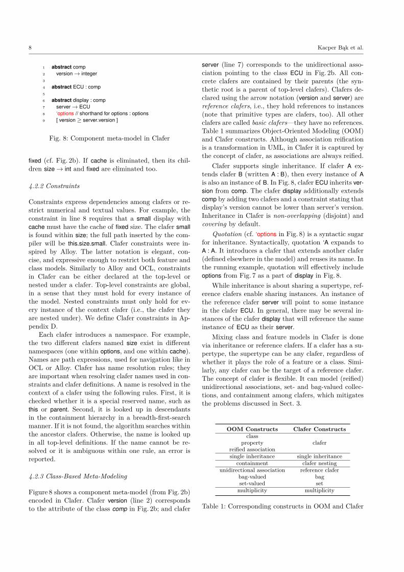
Figure 8 shows a component meta-model (from Fig. 2b)encoded in Clafer. Clafer version (line 2) correspondsto the attribute of the class comp in Fig. 2b; and clafer
server (line 7) corresponds to the unidirectional asso-ciation pointing to the class ECU in Fig. 2b. All con-crete clafers are contained by their parents (the syn-thetic root is a parent of top-level clafers). Clafers de-clared using the arrow notation (version and server) arereference clafers, i.e., they hold references to instances(note that primitive types are clafers, too). All otherclafers are called basic clafers—they have no references.Table 1 summarizes Object-Oriented Modeling (OOM)and Clafer constructs. Although association reificationis a transformation in UML, in Clafer it is captured bythe concept of clafer, as associations are always reified.
Clafer supports single inheritance. If clafer A ex-tends clafer B (written A : B), then every instance of Ais also an instance of B. In Fig. 8, clafer ECU inherits ver-sion from comp. The clafer display additionally extendscomp by adding two clafers and a constraint stating thatdisplay’s version cannot be lower than server’s version.Inheritance in Clafer is non-overlapping (disjoint) andcovering by default.
Quotation (cf. ‘options in Fig. 8) is a syntactic sugarfor inheritance. Syntactically, quotation ‘A expands toA : A. It introduces a clafer that extends another clafer(defined elsewhere in the model) and reuses its name. Inthe running example, quotation will effectively includeoptions from Fig. 7 as a part of display in Fig. 8.
While inheritance is about sharing a supertype, ref-erence clafers enable sharing instances. An instance ofthe reference clafer server will point to some instancein the clafer ECU. In general, there may be several in-stances of the clafer display that will reference the sameinstance of ECU as their server.
Mixing class and feature models in Clafer is donevia inheritance or reference clafers. If a clafer has a su-pertype, the supertype can be any clafer, regardless ofwhether it plays the role of a feature or a class. Simi-larly, any clafer can be the target of a reference clafer.The concept of clafer is flexible. It can model (reified)unidirectional associations, set- and bag-valued collec-tions, and containment among clafers, which mitigatesthe problems discussed in Sect. 3.
OOM Constructs Clafer Constructsclass
claferpropertyreified associationsingle inheritance single inheritance
containment clafer nestingunidirectional association reference clafer
bag-valued bagset-valued setmultiplicity multiplicity
Table 1: Corresponding constructs in OOM and Clafer

Clafer: Unifying Class and Feature Modeling 9
1 abstract plaECU : ECU2 plaDisplay : display 1..23 [ no cache ]4 [ server = parent ]5
6 ECU1 : plaECU7
8 ECU2 : plaECU ?9 master→ ECU1
Fig. 9: Architectural template in Clafer
4.3 Solving Problem 2: Mapping Feature toComponent Configurations
Clafer can encode model templates in a way that con-figurations are always syntactically correct. Figure 9 en-codes the template from Fig. 2d in Clafer. The prede-fined keyword parent points to one of the instances ofplaECU, which is either ECU1 or ECU2. Instead of mak-ing existence of a class optional, it is assumed that theclass exists, but it has the multiplicity 0..1. Its presencecondition becomes a normal constraint that regulatesinstantiation — as it is typically done in class model-ing. The constraint can easily relate feature and classmodels, because they are in a unified notation.
Having defined an architectural template, we can ex-pose the variability points present in it as a product-linefeature model. Figure 10 shows this model (cf. Fig. 2a)along with constraints coupling its features to the vari-ability points of the template. The template in Fig. 9allows the number of displays (plaDisplay under ECU1and ECU2) and the size of every display to vary inde-pendently. We want to further restrict the variabilityas stipulated in the feature model; however, requiringeither all present ECUs to have two displays or all tohave no extra display, and either all present displaysto be small or all to be large. We opted to explain themeaning of each feature in terms of the model elementsto be selected rather than defining the presence con-dition of each element in terms of the features. Bothapproaches are available in Clafer, however.
Constraints allow us to restrict the model to a sin-gle instance (to configure it). Figure 11 shows top-levelconstraints specifying a single product, with two ECUs,two large displays per ECU, and all components in ver-sion 1. The configuration corresponds to the one inFig. 1d. Instance generators [3] can automatically in-stantiate the product line by deriving a configurationof the architectural template as shown in Fig. 12.
Clafer offers the same syntax for specifying bothmodels and instances (configurations), and the lattercan be partial. Figure 12 shows a Clafer model thatencodes exactly one configuration that was previously
1 telematics2 xor channel3 single ?4 dual ?5
6 extraDisplay ?7
8 xor size9 small ?
10 large ?11
12 [ dual⇔ ECU213 extraDisplay⇔#ECU1.plaDisplay = 214 extraDisplay⇔ (ECU2 =⇒ #ECU2.plaDisplay = 2)15 large⇔ !plaECU.plaDisplay.options.size.small16 small⇔ !plaECU.plaDisplay.options.size.large ]
Fig. 10: Feature model with mapping constraints
specified by constraints. The encoding is done by hierar-chical redefinition among clafers — subclassing amongclafers and subclassing among references. For example,in Fig. 9 the clafer plaDisplay is nested under plaECU,thus in Fig. 12 the singleton clafer d1 subclasses plaDis-play and is nested under e1. For reference clafers, thetarget of the reference gets redefined. For example, inFig. 9 the clafer master points to ECU1 and is nested un-
1 [ dual2 extraDisplay3 telematics.size.large ]4 [ all c : comp | c.version = 1]
Fig. 11: Constraints specifying a single product
1 t1 : telematics2 c1 : channel3 d1 : dual4 ed1 : extraDisplay5 s5 : size6 l5 : large7 e1 : ECU18 d1 : plaDisplay9 s1 : server→ e1
10 o1 : options11 s1 : size12 l1 : large13 v1 : version→ 114 d2 : plaDisplay15 s2 : server→ e116 o2 : options17 s2 : size18 l2 : large19 v2 : version→ 120 v3 : version→ 1
21 e2 : ECU222 m1 : master→ e123 d3 : plaDisplay24 s3 : server→ e225 o3 : options26 s3 : size27 l3 : large28 v4 : version→ 129 d4 : plaDisplay30 s4 : server→ e231 o4 : options32 s4 : size33 l4 : large34 v5 : version→ 135 v6 : version→ 1
Fig. 12: A sample configuration (instance) in Clafer

10 Kacper Bąk et al.
Fig. 13: Architecture of Clafer syntax and semantics
der ECU2; in Fig. 12 the clafer m1 (line 16) subclassesmaster, is nested under e2, and points to e1, which is asubclass of ECU1 (line 1). Note that redefinition of basicor reference clafers allows refining their multiplicities.
This capability of seamlessly expressing abstractions(model) and examples (instances) in a single notationis critical for effective example-driven modeling [9,2].
5 Anatomy of a Clafer Model and ItsInstantiation
This section discusses the basic ingredients of Clafersyntax (details in Appendix C) and presents instanti-ation of Clafer models which plays an important rolein model analyses. Many non-trivial model analyses(e.g., checking model consistency) can be reduced tothe problem of finding a model instance by combina-torial solvers. Therefore, instantiation of Clafer mod-els is the primary functionality of the Clafer toolchain.Furthermore, we give semantics to Clafer models viainstantiation (cf. Fig. 13).
The rich semantics of Clafer models is expressible ina concise syntax. We designed the concrete syntax sothat it hides the complexity of its semantics. The mech-anism is shown in Fig. 13. In the figure, the roundedrectangles represent artifacts (e.g., Clafer Model), the ar-rows type represent typing mappings (e.g., Type’), andthe chevrons represent transformations (e.g., Compile).Another convention used in figures througout the pa-per is that shaded shapes are assumed to exist, whereasblank shapes are assumed to be fully derived.
Figure 13 illustrates that a Clafer Model is typed overand required to conform to the Abstract Syntax Tree (AST)Meta-Model (cf. the constraint |=). Then, the Clafer Modelis compiled into an intermediate representation, a Multi-Clafer Shape (MCS), which is typed over and created sothat it conforms to the MCS Meta-Model (cf. the con-straint |=). The MCS structurally resembles the ClaferModel and it is not yet a class diagram as class namescan repeat when classes play different roles. Therefore,
the MCS needs to be transformed into a Class Diagram(CD), which is typed over and created so that it con-forms to the CD Meta-Model. Roughly, the transforma-tion glues classes with the same name playing differentroles into single classes.
At this point, the class diagram can be given to abackend reasoner for instantiation, which creates anObject Diagram (OD) typed over and required to conformto the class diagram CD. Now, the object diagram mustbe “claferized”, that is, transformed into an instanceMulti-Clafer Instance (MCI) typed over and conforming tothe MCS. In the MCI, objects are replicated so that theycan appear in the original positions, as before the glu-ing. The instance MCI can now be decompiled into aClafer Instance. Note, that the Clafer Instance is transi-tively typed over the AST Meta-Model, which explainswhy instances in Clafer have the same notation as theClafer models - they have the same abstract syntax.For example, compare the clafer options from Fig. 7 andits instances o1-o4 in Fig. 12, lines 10, 16, 25, and 31,respectively.
In our toolchain [3], the Clafer compiler first parses atextual Clafer model into its abstract syntax tree ClaferModel and then compiles it into an MCS. Next, the com-piler transforms the MCS into an encoding of a class dia-gram CD in the language of the chosen backend solver,such as, Alloy, SMT-LIB, and Choco 3. The backendsolver then produces object diagrams OD which are in-stances of the class diagram CD. Finally, these ODs aretranslated back to Clafer syntax.
5.1 Clafers as Views onto Class Diagrams
Figure 14a shows a Clafer model where plaECU is atop-level basic clafer with an unrestricted multiplicity.The optional reference clafer master is contained withinplaECU and, simultaneously, has plaECU as a referencetarget. Furthermore, it is possible to navigate from thetop-level plaECU to the one pointed to by master. Fig-ure 14d shows an intuitive meaning of the model, i.e.,a UML class diagram with a reified association beinga loop. This intuitive meaning is precisely captured inFig. 14b by an MCS that follows the concrete syntax ofClafer. MCS defines Clafer models in terms of formalclass diagrams [29] (formal CDs or just CDs for short),which we use as a notation for our semantic domain.In general, an MCS is a tree-like structure composedby joining Clafer Shapes (CSs). A single CS representsa single clafer declaration. In the example, the MCS iscomposed of only one CS.
A formal CD is a graph with additional labels en-coding constraints. For the CD in Fig. 14b, the graphencompasses three nodes and three edges, and the con-straint labels denote multiplicities and a commutativ-

Clafer: Unifying Class and Feature Modeling 11
plaECU ∗
master→ plaECU ?
(a) Clafer model (b) MCS (c) Labeling as a graph mapping (d) UML Class Diagram
Fig. 14: (a) A Clafer model, (b) its compilation, (c) label extraction, (d) the rendering using reified association
ity constraint ([=]). Nodes of the graph (think of UMLclasses) are interpreted as sets (of their instances). Edges(think of UML associations) are interpreted as map-pings, i.e., sets of links mapping elements from the sourceset to the elements of the target set. The commutativityconstraint denotes that the mapping master* is the se-quential composition ofmaster followed by dref. In fact,this equality means that class master together with itspair of associations (parent, dref) can be considered asreification of association master* (which is shown by adashed line in the UML diagram in Fig. 14d).
We use the following notation for maps (edges). Pre-defined maps, e.g., parent, are underlined. By default,maps are partially defined and multi-valued, and aredenoted by arrows with a black triangle head, see, e.g.,the shapes of arrows master and master* in Fig. 14b.An open arrow head (e.g., arrow dref) means that themap is single-valued: each instance of master points toat most one instance of plaECU. A black bullet arrowtail means that the map is total: each instance of masterpoints to at least one instance of plaECU. A black di-amond arrow tail (arrow master) denotes containmentconsidered as a conjunction of two conditions: multi-plicity 1 (there is one and only one instance of plaECUfor an instance of master) and existence dependency(deletion of an instance of plaECU implies the deletionof its nested instance of master). The first conditionis often referred to as non-sharing (and the multiplic-ity is sometimes relaxed to 0..1). The second conditionis also referred to as cascade deletion. Although it isnot expressible in the CD formalism described in thiswork (which does not have any means of expressing dy-namic constraints), it is an important part of Clafersemantics. Existence dependency can be formalized inthe framework of Class Diagrams with dynamic pred-icates described in [30]. Our arrow notation for mapsis summarized in Tab. 2. Table 3 summarizes the dia-gram predicates we use. They are formally defined inAppendices A and B. We mark a non-constrained bag-valued mapping with the label [bag] while being set-valued is assumed by default and we hide the predicate[set]. Note the difference between the arrow heads for ageneral multi-valued mapping (a black triangle) and asingle-valued mapping (an open arrow-head).
Mapping Arrow Intended semanticspartial
bag-valuedNo constraints.
partialset-valued
f(a) is a set for all a ∈A
total for any a ∈ A there isb ∈ f(a).
single-valued for any a ∈ A there isat most one b ∈ f(a).
inclusion A ⊂ B and f(a) = a.
containment for any b ∈ B there isexactly one a ∈ A s.t.f(a) = b.
Table 2: Notational conventions for maps
Notice, however, that the MCS in Fig. 14b is nota valid class diagram, because it contains two classesnamed plaECU. What is the meaning of this strangediagram then? In contrast with class diagrams (wherenames are unique), the Clafer model (and the corre-sponding MCS) distinguishes two different roles that in-stances of the class plaECU can play: (i) being the parentof reference master, and (ii) being the target of the refer-ence. What Fig. 14b actually encodes is a mapping froma diagram of roles to a diagram of classes and associa-tions, as shown in Fig. 14c. The source of the mappingis the carrier graph of the diagram from Fig. 14b. Thetarget is a formal class diagram that makes the mean-ing of the class diagram from Fig. 14d precise. Indeed,as an object of class master is supposed to reify a masterlink, such an object must have a source projection refer-ence (to the source of the association) that returns thesource component of the link, and a target projectionreference (to the target of the association) that returnsthe target component of the link. In Fig. 14c, these pro-jection references are given respectively by parent anddref associations (maps) in the target CD.
The mapping specified in diagram Fig. 14c (label)consists of links assigning labels to roles; they are shownwith dashed lines. The two links targeting at the sameclass plaECU show that class plaECU plays the two rolesof being both the parent and the target of associa-

12 Kacper Bąk et al.
Predicate Shape Intended semanticsname/symbol (elements a, a′, b, b′ range over A,B resp.)
inv maps f, g are mutually inverse iff their spans f∗, g∗ are such.
key fi(a) = fi(a′) for both i = 1, 2 implies a = a′.
= f∗.g∗ = h∗
cover for any b ∈ B there is a ∈ Ai s.t. b ∈ fi!(a) for i=1 or 2, or both.
disj f1!(a) ∩ f2!(a′) = ∅ for all a 6= a′.
mult-trg m ≤ |f(a)| ≤ n.
mult-src m ≤ |g(b)| ≤ n where g is the inverse of f .
Table 3: A signature of diagram predicates (the labels [bag] are omitted)
tion master. Note that the mapping preserves the graphstructure: it maps edges to edges so that their sourcesand targets are respected. This preservation is an im-portant condition to be respected by labeling.
We will say that Fig. 14c describes a view on theclass diagram, and call the mapping label. For a com-plex Clafer model consisting of multiple clafers, therole graph has the shape of multiple triangles joinedtogether into a hierarchical structure (see, for exam-ple, Fig. 17c). Thus, a Clafer model is compiled into anMCS, whose labeling encodes a mapping to a class di-agram. We will again call this mapping label, and saythat it is extracted from the MCS. The mapping la-bel is crucial for claferizing and decompiling of objectdiagrams that instantiate the back-end class diagramsinto instances typed over MCS, in which different rolesplayed by the same object are explicit.
Below we consider Clafer syntax and MCS compila-tion in more detail.
5.2 Clafer Shape
The diagram in Fig. 15a is a more detailed represen-tation of the diagram in Fig. 14b. Nodes of the dia-gram denote roles played by the involved classes, andedges are roles played by mappings (unidirectional asso-ciations). The bidirectional containment association issplit into two mappings, which are declared as mutually
(a) Clafer Shape (b) Class Diagram
Fig. 15: The CS and the corresponding CD of master
inverse (the predicate declaration [inv](master , parent),which is visually shown by the label [inv] hung on thetwo arrows). Furthermore, the diagram carries the mul-tiplicities of the associationsmaster andmaster*, whichare equal because mapping dref is single-valued.
Thus, the diagram of roles is a graph endowed withpredicate labels declaring certain properties of the map-pings involved. We will call such graphs DP-graphs,meaning graphs with diagram predicates. In fact, formalCDs are nothing but DP-graphs in some predefined sig-nature of diagram predicates required to express staticsemantics of UML class diagrams. Now we can say thata single clafer declaration is compiled into a specificDP-graph (formal CD) of a specific shape specified inFig. 16. We call this specific DP-graph a Clafer Shape,and name its elements as shown in the figure.
The clafer shape has a standard visual layout: thesource class is always above the head class; the tar-get class is to right of the head class. The head classindicates the clafer introduced by the compiled decla-

Clafer: Unifying Class and Feature Modeling 13
Clafer Kind Clafer Model Clafer Shape
Basic telematicsextraDisplay m..n
Reference bag displayserver � ECU m..n
Reference set displayserver→ ECU m..n
Table 4: The meaning of a clafer declaration
Fig. 16: Clafer Shape (CS) (without labels)
ration; the source class relates the introduced clafer toits parent in the containment hierarchy. The dref mapand the target indicate the target type of the reference.Note that mappings dref and parent are always single-valued. Among predicate declarations embodied into aclafer shape, all but multiplicity m..n is automaticallyassumed by default; multiplicity m..n is declared by theuser (and is assumed to be 1..1 unless explicitly statedin concrete syntax to be otherwise).
5.3 Kinds of Clafers
There are two kinds of user-defined clafers: basic clafersand reference (bag and set) clafers. We describe themand specify their semantics via generic examples below.Table 4 summarizes the discussion and shows samplemodels and their CSs. Although, the figures use con-crete names, such as display and server, the compilationworks analogically for any clafer of a given kind. Eachof the clafers can be either abstract or concrete.
5.3.1 Basic Clafers
They establish containment hierarchy among clafers bynesting (same as composition in UML). An example isshown in the first row of Tab. 4. A distinction of a basicclafer’s shape is that the maps dref and target and thetarget class are excluded.
5.3.2 Reference Bag Clafers
They correspond to bag-valued references, i.e., two ormore references from the same source instance can pointto the same target instance. The target clafer namefollows the double arrow symbol (�). For example,there may be several connections from a display toECU. The second row of Tab. 4 illustrates a compila-tion of the reference bag clafer server to a correspondingCS. In fact, reference bag clafers follow the structureof basic clafers, but additionally have the target class(cf. Fig. 16). In reference bag clafers, the target map isbag-valued, hence the annotation [bag] on server*.
5.3.3 Reference Set Clafers
They are set-valued references and their name is fol-lowed by the arrow symbol (→). They are similar toreference bag clafers, but the same source instance can-not point to the same target instance multiple times.
The compilation of reference bag and set clafers toCSs is similar, but the latter have an additional pred-icate declaration [key](parent, dref ) (cf. the last row ofTab. 4). The predicate means that each instance thisof the head class is identified by a pair of instances

14 Kacper Bąk et al.
(this.parent, this.dref) from the source and target classes,and hence “rows” in the “table” server are not dupli-cated. Then navigation from the source to the targetresults in a set-valued mapping. In the example, for agiven instance of display, each instance of server pointsto a different instance of ECU, and the mapping server*is set-valued. Conversely, if the target mapping is set-valued, the pair of projections is a key.
5.3.4 Abstract Clafers
Abstract clafers define only a type (no direct instances).We distinguish nested and top-level abstract clafers.The CS of the former is the same as of previously de-scribed clafers. Top-level abstract clafers, on the otherhand, have slightly different CSs: they have no parentin the containment hierarchy, i.e., the CS excludes thehead class and the corresponding maps. When a top-level clafer is declared abstract, then all its descendants(in the containment hierarchy) are declared abstract bydefault; this is the only case in which abstract clafersare nested.
5.3.5 Predefined Clafers
There are several clafers that are predefined in the lan-guage: the clafer Sing and a family Dom of clafers rep-resenting primitive domains (e.g., int for integers, andstring for strings of characters). Sing is very importantalthough it does not appear in the concrete syntax.Each Clafer model by default has Sing as the root ofthe containment hierarchy, and hence Sing is the par-ent of top-level concrete clafers. It also is important inthe context of top-level abstract clafers that have noparent. The synthetic root embodies the concept of ex-istence. In Clafer, being reachable from the syntheticroot is necessary for a clafer to exist when the modelgets instantiated. Sing only has a head class, which issome predefined singleton class {*} also called Sing andhas neither a parent nor a target (see the upper trian-gle in Fig. 17b). Any clafer in Dom is a child of Sing, itshead class is the class of the respective values (integers,strings, etc.), and it does not have a target class.
5.4 Clafer Nesting
A Clafer model is a tree of clafer declarations. In con-crete syntax, that hierarchy is expressed via indenta-tion. For example, master is a child of plaECU in Fig. 17a.Clafers can arbitrarily nest clafers irrespective of theirkind. In particular, reference clafers can nest clafers,which corresponds to nesting properties under UMLassociation classes. In contrast to property nesting inUML, clafers can be nested arbitrarily deeply, however.
Fig. 18: Inheritance among two CSs
Clafer nesting is realized through cojoining CSs whichthen form an MCS. If a clafer B is a child of (nested un-der) clafer A, then the head class of A is also the sourceclass of B, so that the CS of B is plugged into the CSof A such that:
A.head = B.source
For example, Fig. 17b shows three cojoined CSs whereplaECU is a parent of master and Sing is a parent ofplaECU.
Section 5.1 showed that a single CS amounts to alabeling mapping to a CD. Correspondingly, an MCSamounts to a labeling mapping to a bigger CD. Fig-ure 17c presents the extraction of this mapping for ourexample. The mapping itself is specified in Fig. 17c’. TheCD, generated by the mapping label, demonstrates thatlabeling glues together some nodes from the MCS.
5.5 Inheritance
Inheritance between two clafers is defined at the levelof their CSs and means their inclusion: the correspond-ing classes in CS are related by inclusions, as in Fig. 18.Inclusion maps are denoted by hollow-triangle heads,which resemble UML notation for inheritance. Formally,a map m with a hollow-triangle head means a predicatedeclaration [incl](m). The idea of modeling subsettingvia inclusion maps is borrowed from category theory.Figure 19 shows an example. The clafer master underECU2 specializes master under plaECU. Effectively, forreference clafers inheritance is a redefinition. The redef-inition for maps also holds due to commutativity con-dition of maps: supers.head = head.superh. If a CS hasno target (is a basic clafer) or no parent (an abstractclafer), then there is no inclusion between the missingclasses.
Inheritance among any types of clafers is allowed,but it is subject to the following restrictions:

Clafer: Unifying Class and Feature Modeling 15
1 plaECU 0..∗
2 master→ plaECU 0..1
(a) Clafer model
ClassRole LabelSing Sing
plaECU1, plaECU2 plaECUmaster1 master
MapRole Labelparent1 parent1plaECU1 plaECUparent2 parent2master1 mastermaster1* master*dref1 dref
(b) Corresponding MCS (c’) Definition of the mapping label
(c) Corresponding MCS mapped via label defined in (c’) to a CD
(d) An MCI mapped via label* to a sample OD.
Fig. 17: Compilation of a Clafer model to an MCS, gluing into a CD, and instantiation
16 Kacper Bąk et al.
Fig. 19: An example of clafer inheritance
– a basic clafer cannot inherit from a reference clafer(because the subtype would remove the reference);
– a bag clafer cannot inherit from a set clafer (becausethe subtype would remove a constraint);
– if the super-clafer is not a top-level abstract clafer(i.e., it has a parent), then both the sub- and super-clafer must have the same parent in the contain-ment hierarchy (because a clafer cannot have mul-tiple parents).
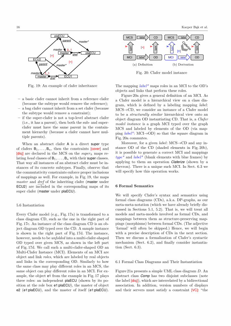
When an abstract clafer A is a direct super typeof clafers B1, . . . ,Bn, then the constraints [cover] and[disj] are declared in the MCS on the superh maps re-lating head classes of B1, . . . ,Bn with their super classes.That way all instances of an abstract clafer must be in-stances of its concrete subtypes. Finally, observe thatthe commutativity constraints enforce proper inclusionsof mappings as well. For example, in Fig. 19, the mapsmaster and dref of the inheriting clafer (master underECU2) are included in the corresponding maps of itssuper clafer (master under plaECU).
5.6 Instantiation
Every Clafer model (e.g., Fig. 17a) is transformed to aclass diagram CD, such as the one in the right part ofFig. 17c. An instance of the class diagram CD is an ob-ject diagram OD typed over the CD. A sample instanceis shown in the right part of Fig. 17d. The instance,however, needs to be unfolded into a multi-clafer-shapedOD typed over given MCS, as shown in the left partof Fig. 17d. We call such a multi-clafer-shaped OD anMulti-Clafer Instance (MCI). Elements of an MCI areobject and link roles, which are labeled by real objectsand links in the corresponding OD. Similarly to howthe same class may play different roles in an MCS, thesame object can play different roles in an MCI. For ex-ample, the object e1 from the example in Fig. 17 playsthree roles: an independent plaECU (shown by its po-sition at the role box e1:plaECU), the master of objecte2 (e1:plaECU), and the master of itself (e1:plaECU).
(a) Definition (b) Derivation
Fig. 20: Clafer model instance
The mapping label* maps roles in an MCI to the OD’sobjects and links that perform these roles.
Figure 20a gives a general definition of an MCI. Asa Clafer model is a hierarchical view on a class dia-gram, which is defined by a labeling mapping label:MCS→CD, we consider an instance of a Clafer modelto be a structurally similar hierarchical view onto anobject diagram OD instantiating CD. That is, a Clafermodel instance is a graph MCI typed over the graphMCS and labeled by elements of the OD (via map-ping label* : MCI→OD) so that the square diagram inFig. 20a commutes.
Moreover, for a given label: MCS→CD and any in-stance OD of the CD (shaded elements in Fig. 20b),it is possible to generate a correct MCI and mappingstype* and label* (blank elements with blue frames) byapplying to them an operation Claferize (shown by achevron). There is a unique such MCI. In Sect. 6.3 wewill specify how this operation works.
6 Formal Semantics
We will specify Clafer’s syntax and semantics usingformal class diagrams (CDs), a.k.a. DP-graphs, as ourmeta-meta-notation (which we have already briefly dis-cussed in Sections 5.1, 5.2). That is, we will treat allmodels and meta-models involved as formal CDs, andmappings between them as structure-preserving map-pings (morphisms) between formal CDs. (The adjective’formal’ will often be skipped.) Hence, we will beginwith a precise description of CDs in the next section.Then we discuss a formalization of Clafer’s syntacticmechanism (Sect. 6.2), and finally consider instantia-tion (Sect. 6.3).
6.1 Formal Class Diagrams and Their Instantiation
Figure 21a presents a simple UML class diagram D. Anabstract class Comp has two disjoint subclasses (notethe label [disj]), which are interrelated by a bidirectionalassociation. In addition, version numbers of displaysand their servers must satisfy a constraint [VC]: “the

Clafer: Unifying Class and Feature Modeling 17
(a) UML CD, D (b) Formal CD, FD
(c) Meta-model of formal class diagrams ([nd] and [ad] are Name Discipline and Arity Discipline constraints resp.)
Fig. 21: Formal Class Diagrams: an instance in UML (a), formal CD rendering (b), and the meta-model (c)
version number of the ECU serving a display must benot lower than the display’s version number”, whichis written in the OCL format below the diagram. Anabstract meaning of this diagram in terms of sets andmappings is that we have a set Comp partitioned intotwo disjoint subsets, which are interrelated by two mu-tually inverse mappings: server that maps displays toECUs, and display that maps an ECU to the displays itserves. The attribute version can be also considered asa mapping that assigns an integer to each component.Finally, this configuration of sets and mappings mustsatisfy the constraint [VC].
This meaning is accurately specified by a formal di-agram FD in Fig. 21b. The latter is a directed graphencompassing four nodes and five arrows, which in addi-tion carries several predicate declarations (constraints)shown in red square brackets. Thus, the diagram is apair FD = (Γ [FD], Φ[FD]) with the first component be-ing the carrier graph, and the second one being theset of constraints (we will also say formulas, hence, thesymbol Φ), which will be formalized shortly. We callsuch formal diagrams formal CDs. We will first discussthe carrier graph and its instantiation in Sect. 6.1.1,and then proceed to constraints in Sect. 6.1.2. Althoughmultiplicities are constraints, we will discuss them inSect. 6.1.1. In Sect. 6.1.3 we give a formal definition offormal CDs by specifying their meta-model. Formaliza-tion of the set-and-mapping semantics of CDs involvesmany details, which we present in Appendix B.1. In
the present section we will assume that the notions of aset and a (partial multi-valued) mapping between setsare intuitively understood; Appendix B.1 supports thisintuition with a system of formal definitions.
6.1.1 Instantiation of Formal CDs, I: The GraphStructure.
Nodes in FD are to be interpreted as sets: JCompK, JIntK,JECUK etc. We will often say “a component” for anelement of set JCompK, “an ECU” for an element ofJECUK etc. Arrows are to be interpreted by mappings(functions) between sets, which map elements from thesource to sets of elements in the target. For example,an ECU is mapped to a set (perhaps, empty) of thedisplays it serves. We recall our convention about map-pings that we have been using (cf. Tab. 2). If the map-ping is defined for each element in the source (and re-sults in a non-empty subset of the target), we call themapping total and denote it by arrow with a bullet tail.If each element from the source, for which the map-ping is defined, is mapped to a singleton, we say thatthe mapping is single-valued and denote it by arrowwith an open-ended head. Thus, mapping server is par-tial single-valued, and version is total single-valued. Incontrast, display is a general mapping, i.e., partial andmulti-valued.
Very important and very special mappings are in-clusions, which are denoted by arrows with a hollowtriangle head — see arrows i1 and i2 in the diagram of

18 Kacper Bąk et al.
Fig. 21b. An inclusion between two sets can be definediff the source is a subset of the target; inclusion mapseach element of the source to itself, but now consid-ered as an element of the target. For example, inclusioni1 means that JECUK ⊂ JCompK and i1(e) = e for alle ∈ JECUK. Thus, inclusion changes the role/type ofECU object e: object i1(e) is a component with all itsECU-properties forgotten. In this way inclusions modelinheritance. As there can be only one inclusion betweena subset and its superset, we can name all inclusions bythe same default name “isA” and omit it in concretevisualizations of formal CDs. Labels i1, i2 in Fig. 21bare IDs of the arrows rather than their names.
The discussion above can be summarized by sayingthat an instance of formal class diagram FD is a mega-mapping J..K : Γ [FD]→ SetMap from the carrier graphof FD into a universe of sets and mappings, SetMap,also arranged as a directed graph: nodes are sets andarrows are mappings between sets. This mega-mappingpreserves the graph structure (nodes are mapped tonodes and arrows to arrows so that their incidence ispreserved), and respects mappings’ properties: arrowswith bullet tails are mapped to total mappings in SetMap,arrows with hollow-triangle heads are mapped to inclu-sion mappings in SetMap, etc.
A mega-mapping J..K is practically equivalent to thestandard UML understanding of instantiation as hav-ing an object diagram typed over a class diagram. In-deed, sets JECUK etc. give us the objects, and mappingsJserverK etc. give us the links. If, for example, for anobject e ∈ JECUK, we have JdisplayK(e) = {d1, .., dn} ⊂JDisplayK, then in the object diagram we create n linksfrom ECU e to displays d1, d2, ...dn, all typed by map-ping display. We will also have a link from e ∈ JECUKto e ∈ JCompK typed by i1, a link from e ∈ JCompKto an integer JversionK(e), and so on. In this way, amega-mapping J..K gives rise to a directed graph GJ..K ofobjects and links, and a typing mapping tJ..K : GJ..K →Γ [FD], which again respects the graph structure. Con-versely, an object diagram O with object-link graph GO
and typing mapping tO : GO → Γ [FD] gives rise to amega-mapping J..KO : Γ [FD]→ SetMap by defining
JECUKO = {n is a node (object) in GO : tO(n) = ECU},JDisplayKO = {n is a node in GO : tO(n) = Display},JserverKO = {a is an arrow (link) in GO : tO(a) = server}
and so on. An accurate formal definition of this con-struction, and a proof of equivalence of the two ways ofinstantiating formal class diagrams (via mega-mappingsinto SetMap and typing), are known in category the-ory under the name of theGrothendieck construction [10].
6.1.2 Instantiation of Formal CDs, II: TheConstraints.
We have already discussed multiplicities—simple con-straints assigned to single arrows. However, the diagramFD also has four constraints shown in square brack-ets, which regulate instantiation of groups of arrows.Three of them, [disj], [cover], and [inv] have a predefinedmeaning and their names are written in small font; thefourth, [VC], has a user-defined meaning specified by theOCL expression in Fig. 21a (links from the label [VC] tothe four arrows, whose instantiation [VC] constrains, arenot shown in the diagram to avoid line clutter).
In the abstract syntax, the four constraints encodethe following expressions: [inv](server, display), [disj](i1,i2 ),[cover](i1,i2 ), and [VC](server , i1, i2, version) of the for-mat P (a1, ...an) with P a predicate name and a1...an
a list of arguments matching the predicate’s arity. Thepredicate [inv] can be declared only for two arrows be-tween two classes going in the opposite directions, [cover]works for a group of arrows with a common target, and[disj] has the same arity. We can use these arities tocheck correctness of constraint declarations. Similarly,multiplicities are constraints for a single arrow, and di-agram FD actually declares several such constraints:[single-valued](server), [total](version), [0..5](display), etc.,and also [incl](i1 ), [incl](i2 ).
In contrast, the arity of the user-defined predicate[VC] is given by the constraint declaration, and the ar-ity condition is automatically true as soon as the ex-pression is syntactically correct. In fact, any OCL, oranother constraint language, expression written over aclass diagram can be trivially considered as a respectivediagram predicate declaration of the aforementionedformat. Moreover, there exists a compact set of prede-fined diagram predicates, which allows one to expressany FOL (and actually higher-order too) constraint asa composition of these predefined predicates [47]. Thisresult may be useful for our future work on Clafer, butwe do not need it here. The Clafer compiler treats aClafer constraint expression as a property of the re-spective configuration of classes and mappings, like itis done in OCL.
Each predefined predicate has a certain semanticsin terms of sets and mappings (cf. Tab. 3). For exam-ple, two mappings with a common target satisfy thepredicate [cover] iff any element in the target belongs tothe image of one of the mappings, or to both. The lat-ter possibility is prohibited by predicate [disj]. Predicate[inv] holds iff the two mappings are mutually inverse. Forexample, for any ECU e and display d, e ∈ JserverK(d)iff d ∈ JdisplayK(e). Semantics of user-defined predicatesis given by the user. Thus, a legal instance of diagramFD is a mega-mapping J..K such that all constraints de-

Clafer: Unifying Class and Feature Modeling 19
clared in Φ[FD] are satisfied. Note that we have mod-eled abstractness of class Comp by requiring the twoinclusions to be covering, i.e., stating that
JCompK = JECUK ∪ JDisplayK
and hence any component is either ECU or Display (butnot both because of the [disj] declaration). In contrast tothe UML class diagram in Fig. 21a, writing the nameComp in italic in the formal CD is a pure decorationwithout semantic meaning.
6.1.3 Meta-model
A meta-model of formal CDs is specified in Fig. 21c. Itis itself a formal CD, MCD, and any valid formal CDshould have a valid instance J..K : MCD → SetMap.The meaning of the central part (dashed-framed) of theformal CD is standard; we show how it works for ourformal CD FD in Fig. 21b. The latter is the followinginstance of the meta-model (we denote names of meta-classes in Small Capital font):
JClassK = {#Comp,#Int,#ECU,#Display},JMapK = {#version, i1, i2,#server,#display},
where #xyz denotes the ID of the classifier named xyz.This gives us the set JClassifierK = JClassK∪JMapK.Mapping JnameK is defined as follows:
JnameK(#ECU) = “ECU” ∈ JStringK,JnameK(#display) = “display” ∈ JStringK,
. . . ,
JnameK(i1) = JnameK(i2) = “isA” ∈ JStringK,
where JStringK is the set of all possible strings, andstring “isA” is the default name of all inclusions.
Definition of mappings JsoK and JtaK are also clear:
JsoK(#display) = #ECU,
JtaK(#server) = #ECU,
and so on. And JInclK={i1,i2} so that JInclK ⊂ JMapKas required. It is also easy to check that mega-mappingJ..K is a correct graph morphism, and all multiplicitiesare also respected.
Let us consider the meaning of the left part of themeta-model (to the left of the dashed frame). Meta-class SING is a singleton with a predefined (but op-tional) instantiation by a class Sing, which, in turn,is instantiated (optionally) by a predefined object *.That is, for any formal CD F instantiating MCD, setJSINGKF is (either empty or) the same fixed single-ton class {Sing}; for any object diagram O instantiating
F , JSingKO is (either empty or) the same fixed single-ton {*}. Meta-class SING is not instantiated in CD inFig. 21b, but in formal CDs generated by the Clafercompiler, class Sing is always present as discussed inSect. 5.3.
Similarly, the meta-class Dom is instantiated by(names of) predefined primitive-value domains like Int,String, or Bool, which, in turn, are instantiated by pre-defined sets of values. For example, for formal CD inFig. 21b, JDomK={#Int}, and instances of #Int are pre-defined integer values. Thus, for a CD F , we have a setof predefined classes JPredefKF , which have predefinedfixed names, say, JnameK(#Int) = “Int” ∈ JPredefStrKand are common for all CDs. Constraint [nd] (read NameDiscipline) requires that names of predefined classes betaken from predefined strings, and that names of user-defined classes be taken outside predefined strings.
Finally, the right part of the meta-model defines for-mulas. Meta-class Signature is instantiated by predi-cates, which can be used in constraint declarations. Forthe diagram in Fig. 21b,
JSignatureK = {[cover],[disj],[inv],[incl],[set],[VC]}∪ {[m..n]:m ∈ N, n ∈ N ∪ {∗}}
although not all multiplicities are used. Meta-class For-mula is instantiated by constraint formulas declared inthe CD, and the constraint [key] states that a formulaφ ∈ JFormulaK is uniquely determined by its predi-cate symbol P = JpredK(φ) and its list of arguments(a1, ..., an) = JargsK(φ) (we consider a list of formulasas a bag/family of formulas indexed by natural num-bers, see Appendix B.1.2). That is, a formula is actu-ally a pair (P, (a1...an)), which we typically write asP (a1...an). For example, for the diagram in Fig. 21b,the set JFormulaK is
{[disj](i1, i2), [cover](i1, i2), [inv](#server,#display),[incl](i1), [incl](i2), [0..5](#display),[1..1](#version), [0..1](#server)[VC](#server, i1 , i2 ,#version)}
plus three default declarations
{[set](#version), [set](#server), [set](#display)}.
Importantly, the list of arguments in the formulaP (a1, .., an) must match the arity of predicate symbolP as it was discussed in Sect. 6.1.2. In detail, the map-ping args is bag-valued, and the indexing set for a for-mula φ (Appendix B.1.2) is the list of the arrows of thearity graph of predicate pred(φ); a precise formal defi-nition can be found in Appendix B.1.2. This conditionis encoded by a meta-constraint [ad] (read Arity Dis-cipline), which is a part of the meta-model like othermeta-constraint declarations: [key](args, pred), [nd], etc.

20 Kacper Bąk et al.
Thus, legal instances of the meta-model Fig. 21c are(formal) CDs or, synonymously, DP-graphs.
6.2 Formalizing Clafer Syntax
6.2.1 Architecture of Clafer’s syntactical mechanism
We already presented the syntactical mechanism of Claferin Fig. 13. There are three meta-models: Abstract Syn-tax Tree (AST) Meta-Model, Multi-Clafer Shape (MCS) Meta-Model, and Class Diagram (CD) Meta-Model. The MCSmeta-model includes the AST meta-model and extendsit with new properties of clafers. The MCS meta-modelalso includes the CD meta-model but names its ele-ments differently. We describe the meta-models in Sec-tions 6.2.2 and 6.2.3, respectively.
Formally, all nodes at the model and meta-modellevels in Fig. 13 are CDs (i.e., DP-graphs) The verticalarrows are graph morphisms typing elements in theirsource graphs by elements in the target graphs. In ad-dition, these typing mappings must satisfy constraintsdeclared in their target graphs (meta-models). We vi-sualize this requirement by labeling the mapping withthe entailment symbol |=.
6.2.2 Abstract Syntax Tree
The AST meta-model (cf. Fig. 22) specifies the abstractsyntax of Clafer. The AST corresponds to a grammarof Clafer models (cf. Fig. 27, Appendix C). We discussthe meta-model starting from the left. Each clafer has aname, some multiplicity and, optionally, a super-type.The class BasicClafer stands for a basic clafer decla-ration; RefClafer for reference clafer; and RefSet-Clafer for reference set clafer. The map target spec-ifies the target of a reference clafer, and the map ab-stract indicates whether a clafer is abstract. The classDom represents a family of primitive domain clafers(for example, clafer Int is a basic clafer whose parent issynthetic root); the singleton class Sing represents thesynthetic root clafer. The map parent establishes thecontainment hierarchy among Clafers. It is specifiedfor each clafer besides the synthetic root and top-levelabstract clafers: for any clafer C, if C.parent = ⊥ andC 6= Sing, then C.abstract = true.
The class Constraint represents user-defined con-straints in Clafer models. The map context points tothe clafer in which a constraint was declared. The mapscope indicates a bag of clafers that each constraintrefers to (besides the context clafer). For example, groupcardinalities, such as the xor group cardinality in line2 in Fig. 7, are simple constraints that relate a claferwith its children. There, the constraint c relates the
Fig. 22: Clafer AST Meta-Model
clafer size with its children small and large; formally:
JcontextK(c) = size,
JscopeK(c) = {small, large}.
The constraint language of user-defined constraints isspecified in Appendix D. The language can be consid-ered as a part of the meta-model.
6.2.3 Multi-Clafer Shape
The result of compilation is an MCS. The meta-modelin Fig. 23 defines the structure of an MCS. As discussedin Sect. 5.2, in Fig. 16, each clafer actually declares a la-beled clafer shape, i.e., a labeled graph of class and maproles. The three leftmost vertical arrows (head, source,and target) give three classes (i.e., class roles) that makeup the shape of a clafer: the head class is always present,but the source (parent) and the target are optional de-pending on the kind of clafer. The next four verticalarrows in the middle (head, parent, dref, target) givefour maps (all optional) that make up a clafer shape.The three rightmost vertical arrows give optional inclu-sion maps, if the clafer has a supertype. For example,the Clafer model in Fig. 17b amounts to the followinginstance of the meta-model:
JSingK = ##Sing,
JClaferK = {##Sing,##plaECU,##master},JparentK(##plaECU) = ##Sing,
. . .
JSINGK = #Sing,
JsourceK(##plaECU) = #Sing,
JheadK(##plaECU) = #plaECU1
. . .
where ##xyz refers to the clafer named xyz, and #xyzrefers to the class role named (labeled by) xyz.
MCS is augmented with diagram predicates overmaps, which are represented by class Formula and are
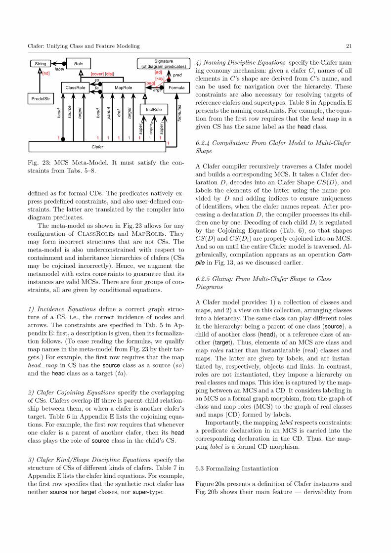
Clafer: Unifying Class and Feature Modeling 21
Fig. 23: MCS Meta-Model. It must satisfy the con-straints from Tabs. 5–8.
defined as for formal CDs. The predicates natively ex-press predefined constraints, and also user-defined con-straints. The latter are translated by the compiler intodiagram predicates.
The meta-model as shown in Fig. 23 allows for anyconfiguration of ClassRoles and MapRoles. Theymay form incorrect structures that are not CSs. Themeta-model is also underconstrained with respect tocontainment and inheritance hierarchies of clafers (CSsmay be cojoined incorrectly). Hence, we augment themetamodel with extra constraints to guarantee that itsinstances are valid MCSs. There are four groups of con-straints, all are given by conditional equations.
1) Incidence Equations define a correct graph struc-ture of a CS, i.e., the correct incidence of nodes andarrows. The constraints are specified in Tab. 5 in Ap-pendix E: first, a description is given, then its formaliza-tion follows. (To ease reading the formulas, we qualifymap names in the meta-model from Fig. 23 by their tar-gets.) For example, the first row requires that the maphead_map in CS has the source class as a source (so)and the head class as a target (ta).
2) Clafer Cojoining Equations specify the overlappingof CSs. Clafers overlap iff there is parent-child relation-ship between them, or when a clafer is another clafer’starget. Table 6 in Appendix E lists the cojoining equa-tions. For example, the first row requires that wheneverone clafer is a parent of another clafer, then its headclass plays the role of source class in the child’s CS.
3) Clafer Kind/Shape Discipline Equations specify thestructure of CSs of different kinds of clafers. Table 7 inAppendix E lists the clafer kind equations. For example,the first row specifies that the synthetic root clafer hasneither source nor target classes, nor super-type.
4) Naming Discipline Equations specify the Clafer nam-ing economy mechanism: given a clafer C, names of allelements in C’s shape are derived from C’s name, andcan be used for navigation over the hierarchy. Theseconstraints are also necessary for resolving targets ofreference clafers and supertypes. Table 8 in Appendix Epresents the naming constraints. For example, the equa-tion from the first row requires that the head map in agiven CS has the same label as the head class.
6.2.4 Compilation: From Clafer Model to Multi-ClaferShape
A Clafer compiler recursively traverses a Clafer modeland builds a corresponding MCS. It takes a Clafer dec-laration D, decodes into an Clafer Shape CS(D), andlabels the elements of the latter using the name pro-vided by D and adding indices to ensure uniquenessof identifiers, when the clafer names repeat. After pro-cessing a declaration D, the compiler processes its chil-dren one by one. Decoding of each child Di is regulatedby the Cojoining Equations (Tab. 6), so that shapesCS(D) and CS(Di) are properly cojoined into an MCS.And so on until the entire Clafer model is traversed. Al-gebraically, compilation appears as an operation Com-pile in Fig. 13, as we discussed earlier.
6.2.5 Gluing: From Multi-Clafer Shape to ClassDiagrams
A Clafer model provides: 1) a collection of classes andmaps, and 2) a view on this collection, arranging classesinto a hierarchy. The same class can play different rolesin the hierarchy: being a parent of one class (source), achild of another class (head), or a reference class of an-other (target). Thus, elements of an MCS are class andmap roles rather than instantiatable (real) classes andmaps. The latter are given by labels, and are instan-tiated by, respectively, objects and links. In contrast,roles are not instantiated, they impose a hierarchy onreal classes and maps. This idea is captured by the map-ping between an MCS and a CD. It considers labeling inan MCS as a formal graph morphism, from the graph ofclass and map roles (MCS) to the graph of real classesand maps (CD) formed by labels.
Importantly, the mapping label respects constraints:a predicate declaration in an MCS is carried into thecorresponding declaration in the CD. Thus, the map-ping label is a formal CD morphism.
6.3 Formalizing Instantiation
Figure 20a presents a definition of Clafer instances andFig. 20b shows their main feature — derivability from

22 Kacper Bąk et al.
the respective CD instances. Whereas the two model-level artifacts are formal CDs (DP-graphs), the twoinstance-level artifacts are merely graphs (Clafer modelinstances, like ODs, do not carry constraints). All verti-cal arrows are typing mappings that respect the graphstructure and satisfy the constraints (note the symbols|=). The right “column” of models conforms to the stan-dard MOF architecture of instantiation; the left columnis its counterpart for Clafer. All horizontal mappingsare also graph morphisms; in addition, the mappingslabel respect constraints (are DP-graphs morphisms).Chevron Claferize denotes an operation that completesan instance of a CD, i.e., a pair (OD, type) to a Claferinstance (MCI, type*) (which is traced to the originalinstance via the mapping label*). Below we will oftenrefer to instances by their source graphs, and say “in-stance OD” and “instance MCI”.
The operation Claferize recursively traverses an MCSand OD and builds a corresponding MCI. It takes eachsource class R from MCS, finds its instances O in OD,such that label(R) = type(O), and, for each O, createsa source object role in MCI. It then finds and addscorresponding instances of the mappings head, source,etc. If the mapping target is instantiated for a givensource object O, then it also adds the target object. Af-ter processing the class role R, the operation processesits children (pointed to by the mappping head) one byone, for each instance O.
Let us illustrate how the operation Claferize worksbased on the example from Fig. 17d. Note that in theclass diagram CD, the class plaECU plays two roles: thesource of the map master and the target of the map dref.The Claferize constructs the MCI in such a way that thediagram commutes, that is, type*.label = label*.type.
As we have seen in Sect. 6.1, an instance of a CDcan be seen as a mega-mapping J..K : CD → SetMap.In the example, we have the instance JSingKOD={*},JplaECUKOD={e1, e2}, Jmaster*KOD={m21, m11}, etc.Sequential mapping composition label.J..KOD then yieldsan instance of MCS. That is, for any element x of graphMCS, we define JxK=Jx.labelKOD, which gives us a mega-mapping J..K : MCI → SetMap. The latter can berepresented by a typed graph (due to the Grothendieckconstruction discussed at the end of Sect. 6.1.1), whichwe denote by MCI. In other words, we set JxKMCI =Jx.labelKOD=x.label.J..KOD for all elements x of graph MCS.
Note that as the mapping label maps two differentroles into one class (JplaECU1KMCI = JplaECU2KMCI = {e1,e2}), each object ei, i = 1, 2 may play two roles of be-ing the source and the target of master links. Hence,in the carrier graph MCI we have three clones of e1(e1:plaECU1 as a source, and e1:plaECU2 as a targetplayed twice: once as a target of e1 and once as a tar-get of e2) and one clone of e2 (only e2:plaECU1 as a
source, because e2 does not play the role of a target).Other OD elements are not cloned because the mappinglabel only glues together classes plaECU1 and plaECU2.Mapping label∗0:MCI → OD provides traceability ofroles to objects, particularly, it glues together clonesinto their original objects.
Note that graph MCI is properly typed over graphMCS. It also satisfies all multiplicities declared in MCSbecause the mapping label carries these predicates intoCD and the instance OD satisfies them.
7 Analytical Evaluation
We examine the extent to which Clafer meets its designgoals from Sect. 3.
1. Clafer provides a concise notation for feature model-ing. This can be seen by comparing Clafer to TVL, astate-of-the-art textual feature modeling language [15].Figure 24 shows the TVL encoding of the featuremodel from Fig. 7. Conciseness can be measured asthe number of elements used to encode a model. TheClafer model has slightly fewer concepts than theTVL model. Feature models in Clafer look very sim-ilar to feature models in TVL, except that TVL usesexplicit keywords (e.g., to declare groups), braces fornesting, and feature names must be unique.Clafer’s language design reveals several key ingredi-ents allowing a class modeling language to providea concise notation for feature modeling:– Concept unification: The concept clafer unifies
basic constructs of structural modeling, such asclass, association, and property (which includesattribute, reference, and role). Such a unifica-tion enables arbitrary property nesting, whichallows us to concisely specify feature models ina class modeling language. Neither UML nor Al-loy provide this mechanism; there, associationsand classes are declared separately, and proper-ties cannot be arbitrarily nested. Although UMLoffers association classes, they cannot use prim-itive domains as association ends.
1 Options group allof {2 Size group oneof { Small, Large },3 opt Cache group allof {4 CacheSize group allof {5 SizeVal { int val; },6 opt Fixed7 }8 },9 Constraint { (Small && Cache)→ Fixed; }
10 }
Fig. 24: Options feature model in TVL

Clafer: Unifying Class and Feature Modeling 23
– Instance composition and type nesting: Clafernesting accomplishes instance composition andtype nesting in a single construct. UML providescomposition, but type nesting is specified sepa-rately (cf. Fig. 5b). Alloy has no built-in sup-port for composition and thus requires explicitparent-child constraints. It also has no signaturenesting, so name clashes need to be avoided us-ing prefixes or alike.
– Default singleton multiplicity: All clafers that havea parent in the containment hierarchy, are single-tons by default. It allows one to specify manda-tory features without declaring their multiplicityexplicitly in the concrete syntax. In UML andAlloy, on the other hand, associations are multi-valued by default.
– Group constraints: Clafer’s group constraints areexpressed concisely as intervals. In UML groupscan be specified in OCL, but using a lengthyencoding, explicitly listing features belonging tothe group. The same applies to Alloy.
– Constraints with default quantifiers: Default quan-tifiers on relations enable writing constraints thatlook like propositional logic, although their un-derlying semantics is FOL. For example, clafernames in the last line in Fig. 7 would be precededby the quantifier some (cf. lines 11-13 in Fig. 26in Appendix C). Name resolution rules furthercontribute to the conciseness of constraints.
– Navigation over optional clafers: Navigation ex-pressions of the form n1.n2 . . . nm encompass nav-igation along the clafer hierarchy and occur inconstraints (e.g., in the last line of Fig. 8). Eachof the names ni may refer to a clafer of anymultiplicity; in particular, the clafer n1 may beoptional, whereas n2 mandatory. In Clafer andAlloy, all navigation expressions uniformly eval-uate to a set (either empty or not). In OCL,however, one needs to explicitly check if navi-gation over an optional element evaluates to anempty set before proceeding to the next element.Otherwise, the navigation results in an unde-fined value indicating an error. Formally, uncon-ditional mapping composition is defined in OCLfor only total mappings, whereas in Clafer andAlloy one can compose partial mappings as well.
2. Clafer provides a concise notation for meta-modeling.Figure 25 shows the meta-model of Fig. 8 encoded inKM3 [43], a state-of-the-art textual meta-modelinglanguage. The most visible syntactic difference be-tween KM3 and Clafer is the use of explicit key-words introducing elements and mandatory bracesestablishing hierarchy. Both models have the samenumber of concepts. KM3, however, cannot express
1 class Comp {2 reference version : integer3 }4
5 class ECU extends Comp {}6
7 class Display extends Comp {8 reference server : ECU9 attribute options : Options
10 }
Fig. 25: Component meta-model in KM3
additional constraints in the model. They are spec-ified separately, e.g., as OCL invariants.
3. Clafer allows one to concisely mix feature and meta-models. Clafer integrates subclassing into hierarchi-cal modeling. Clafers at any nesting level in the con-tainment hierarchy can subclass other clafers. Inher-itance among clafers is a semantically rich opera-tion. For example, inheritance among two referenceclafers introduces two classes (head and target), fourmaps (head, parent, dref, and head*), and three in-clusions (heads, headh, and headt), with all the con-straints regulating well-formedness of CS and inher-itance. Using inheritance, one can reuse feature orclass types in multiple locations; reference clafers al-low reusing both types and instances. Feature andclass models can be related via constraints.
4. Clafer tries to use a minimal number of conceptsand has uniform semantics. While integrating fea-ture modeling into meta-modeling, our goal was toavoid creating a language with duplicate concepts.In Clafer, there is no distinction between class andfeature types; they are all clafers. Features are rela-tions and, besides their obvious role in feature mod-eling, they also play the role of attributes in meta-modeling.We also contribute a simplification to feature mod-eling: Clafer has no explicit feature group construct;instead, every clafer has a group cardinality to con-strain the number of children. This is a significantsimplification; we no longer need to distinguish be-tween grouping features (features used purely forgrouping, such as menus) and feature groups. Thegrouping intention and grouping cardinalities are or-thogonal: any clafer can be annotated as a groupingfeature, and any clafer may choose to impose group-ing constraints on children. This idea has also beenadopted in the current draft of CVL [39].Finally, both feature and class modeling have uni-form semantics. Syntactic and semantic unificationin Clafer keeps the language small, allows for uni-form representation of models, and also simplifiesdevelopment of tools for model analyses. Further,
24 Kacper Bąk et al.
unification has the potential of simplifying modelevolution as fewer special cases (concepts) need tobe considered. In general, however, syntactic unifi-cation may also have some drawbacks, such as a lackof correspondence between the modeler’s intent andnative support for that intent in the language, wors-ened model comprehension, and less efficient modelanalyses. On the other hand, one could easily in-troduce two subclasses of clafer: class and feature,allowing the user to state an intention explicitly.All the tools, however, could still benefit from thesemantic unification by looking at instances of fea-tures and classes as instances of clafer.
8 Related Work
Clafer builds on our several previous works, includ-ing encoding feature models as UML class models withOCL [23]; a Clafer-like graphical profile for Ecore, hav-ing a bidirectional translation between an annotatedEcore model and its rendering in the graphical syn-tax [63]; and the Clafer-like notation used to specifyFramework-Specific Modeling Languages (FSMLs) [4].Moreover, feature models have been characterized asviews on class diagrams (referred to as ontologies) in[22]. None of these works provided a proper languagedefinition that unifies feature and class modeling, anddid not provide implementation like Clafer; also, theylacked Clafer’s concise constraint notation. Althoughwe introduced Clafer earlier [13], our previous worklacked precise semantics because semantic unificationposed a major challenge. In our current work, we pre-cisely specify the unification on feature and class mod-eling constructs and present Clafer’s semantics.
Cardinality-based feature models have been formal-ized in [21] as context-free grammars, and in [50] us-ing set theory. None of the works covers references, at-tributes, and a constraint language that can deal withmultiply-instantiated features. Our work is more com-plete in that sense and, in fact, subsumes cardinality-based feature modeling, equipping it with inheritance.Also, none of the works considers unification of featureand class models, whereas we precisely show how it canbe done.
TVL is a textual feature modeling language [15]. Itfavors the use of explicit keywords, which some softwaredevelopers may prefer. The language covers Booleanfeatures and features of other primitive types such asinteger. The key difference is that Clafer is also a classmodeling language with multiple instantiation, refer-ences, and inheritance. It would be interesting to pro-vide a translation from TVL to Clafer. The oppositetranslation is only partially possible.
Common Variability Language (CVL) is an ObjectManagement Group (OMG) proposal for a standard forspecifying and resolving variability [39]. CVL is beingdesigned by a working group whose members includevariability modeling tool vendors, industrial practition-ers, and academics. In contrast with other works, CVLmodels are not self-contained. CVL allows for intro-ducing variability into any existing model that con-forms to the MOF meta-model. In particular, it can beused to create families of UML models. Clafer models,on the other hand, are self-contained. They can spec-ify variability over existing models, but both would beencoded in Clafer (as in our running example). Simi-larly to UML, CVL has explicit syntactical construc-tions for different concepts. For example, depending onfeature type it is either choice (Boolean feature), clas-sifier (feature with multiplicity), or parameter (featurewith attribute). In Clafer, the three concepts are unifiedinto clafer. CVL provides a constraint language that isstratified into: 1) basic constraint language that speci-fies propositional constraints; and 2) full constraint lan-guage that provides full expressivity of OCL. Clafer hasone constraint language that is inspired by Alloy con-straints. It has the same expressivity as FOL. Further-more, it treats Boolean features as singleton clafers,therefore navigation over clafers results in an emptyset, in the worst case. In CVL, navigation may re-sult in an unknown value if an element does not ex-ist. CVL is a diagrammatic language, while Clafer ismostly textual (although graphical renderings exist).Finally, CVL aims at modeling and resolving variabil-ity, whereas Clafer excells in variabilty modeling andanalysis. It can be used as a back-end for analyses ofCVL models.
Kconfig and CDL [12] are languages for modelingvariability of operating systems: the Linux kernel andeCos. They have a variety of constructs and mix vari-ability with mechanisms to control how models are pre-sented to users in a configurator. Clafer is general-purpose,has one construct, and is user-interface agnostic. It canexpress Kconfig and CDL models, except for the UIaspects.
Asikainen and Männistö present Forfamel, a unifiedconceptual foundation for feature modeling [6]. The ba-sic concepts of Forfamel and Clafer are similar; both in-clude subfeature, attribute, and subtype relations. Themain difference is that Clafer’s focus is to provide con-cise concrete syntax, such as being able to define fea-ture, feature type, and nesting by stating an indentedfeature name. Also, the conceptual foundations of For-famel and Clafer differ; e.g., features in Forfamel corre-spond to Clafer’s instances, but features in Clafer areboth types and instances. Also, a feature instance inForfamel can have several parents; in Clafer, an instance

Clafer: Unifying Class and Feature Modeling 25
has at most one parent. These differences likely stemfrom the difference in perspective: Forfamel takes a fea-ture modeling perspective and aims at providing a foun-dation unifying the many existing extensions to featuremodeling; Clafer limits feature modeling to its originalFeature-Oriented Domain Analysis (FODA) scope [45],but integrates it into class modeling. Finally, Forfamelconsiders a constraint language as out of scope, hintingat OCL. Clafer comes with a concise constraint nota-tion.
Nivel is a meta-modeling language, which was ap-plied to define feature and class modeling languages [5].It supports deep instantiation, enabling concise defini-tions of languages with class-like instantiation seman-tics. Clafer’s purpose is different: to provide a concisenotation for combining feature and class models withina single model. Nivel could be used to define the ab-stract syntax of Clafer, but it would not be able tonaturally support our concise concrete syntax.
In essence, Alloy [41] is a class modeling languagethat reduces OOM to two primitives: signatures (typedsets) and relations. The former correspond to classes;the latter to associations. Alloy can encode and analyzemore conceptually complex UML class diagrams [1].In the context of variability modeling, Alloy has thesame shortcomings as UML class diagrams (cf. Sect. 3).Clafer, on the other hand, was designed to support vari-ability modeling and hierarchical models.
As mentioned earlier, class-based meta-modeling lan-guages, such as KM3 [43] and MOF [54] cannot ex-press feature models as concisely as Clafer. Further-more, Clafer covers the same scope as MOF, but isbased on fewer concepts, as a clafer represents classes,attributes, and relationships.
Decision models group decisions and focus on prod-uct derivation from a product family [20]. Notationsfor specifying decision models include a tabular nota-tion [61] and Synthesis [62]. Clafer models are more ex-pressive, and therefore subsume decision models (mod-ulo language features controlling UI aspects such as vis-ibility). In fact, owing to unification, Clafer can encodevariability, class, and meta-models.
A rigorous approach to unification of different typesof associations based on mathematical operations withmappings, particularly, tabulation, was proposed in [29].Clafer develops this idea further by introducing: 1) in-heritance among clafers, 2) the ability to arbitrarilynest properties, 3) a naming discipline that compactssyntax, and 4) the notion of multi-clafer shape and thecorresponding hierarchical view on Class Diagrams.
Formalization and unification of different views onrelationships and properties has been done in concep-tual modeling, e.g., [65,25]. In contrast to our work,they typically focus on complex semantic aspects rather
than seemingly simple tabular and navigational aspects,and use first-order rather than diagrammatic logic andalgebra.
Refactoring of UML class diagrams is a practical ac-tivity performed during model evolution [64,8]. We ac-knowledge the importance of refactorings, but our ideawith Clafer is more radical: we conjecture that unifi-cation of modeling concepts reduces the number of re-quired model refactorings.
Formalization of conceptual modeling constructs withina framework based on diagram predicates and opera-tions over sets and mappings was proposed in [28,30].The subsequent idea to interpret various diagrammaticnotation used in structural modeling as different visual-izations of the same format of DP-graphs is developedin [31] (where DP-graphs are called sketches). Particu-larly, considering UML class diagrams as visualizationsof formal class diagrams is elaborated in [27,29]. Sev-eral applications of DP-graphs to model-driven softwareengineering are developed in [59,60]
Relating problem-space feature models and solution-space models has a long tradition. For example, featuremodels have been used to configure model templatesbefore [18,36]. That work considered model templatesas superimposed instances of a meta-model and pres-ence conditions attached to individual elements of theinstances; however, Clafer implements model templatesas specializations of a meta-model. Such a solution al-lows us treating the feature model, the meta-model, andthe template at the same meta-level, simply as partsof a single Clafer model. This design allows us to el-egantly reuse a single constraint language at all theselevels and to relate them. As another example, Janotaand Botterweck show how to relate feature and archi-tectural models using constraints [42]. Again, our workdiffers from this work in that our goal is to providesuch integration within a single language. Such inte-gration is given in Kumbang [7], which is a languagethat supports both feature and architectural models,related via constraints. Kumbang models are translatedto Weight Constraint Rule Language (WCRL), whichhas a reasoner supporting model analysis and instanti-ation. Kumbang provides a rich domain-specific vocab-ulary, including features, components, interfaces, andports; however, Clafer’s goal is a minimal uniform lan-guage covering both feature and class modeling, andserving as a platform to derive such domain specificlanguages, as needed.
9 Conclusion
Clafer closes the gap between feature and class modelsand provides improvements on both sides. We showedhow the essential modeling concepts can be unified both
26 Kacper Bąk et al.
syntactically and semantically, which allows for arbi-trary property nesting and uniform representation offeature and class models. Clafer subsumes cardinality-based feature modeling with references. We are notaware of other works that precisely define semantics ofsuch models. We provided semantics in a structurallyexplicit way, as MCSs resemble models in concrete syn-tax. Furthermore, the work on formal semantics gaveus new insights and helped to fix the language (e.g.,clarified the meaning of reference clafers and naviga-tion through the clafer hierarchy).
Our work contributes to the design of modeling no-tations and model analyses. Clafer can encode rich struc-tural models, e.g., domain models, variability models,class models. Unified syntax and semantics allow usinga common infrastructure for reasoning on a large vari-ety of models. We have implemented reasoning supportbased on Alloy, Z3 SMT, and Choco 3 CSP solvers.
Our work intends to help modelers express and an-alyze complex Software Product Lines. We have pre-viously shown that a wide range of realistic featuremodels, meta-models, and model templates can be ex-pressed in Clafer and that useful analyses can be runon them within seconds [13]. The recent thesis demon-strates using Clafer for modeling the three levels ofEAST-ADL architecture on an example of complex au-tomotive electronic/electric architecture and reasoningover such an integrated model [51].
This work has also implications for programminglanguage design. Current OO programming languagessuffer from the same problems as UML class diagrams.The need for arbitrary object nesting (declaring con-tainment and the type of contained object) has beenrecognized in, for example, JavaScript Object Notation(JSON) and protocol buffers.
In the future, we would like to carry out empiricalstudies to explore the benefits and disadvantages of con-cept unification in practical modeling. Other promisingdirections for future work include adding support for:1) domain-specific abstractions in Clafer, 2) modular-ity to provide visibility and variability interfaces, and3) behavioral modeling to express the evolution of statespecified by Clafer models over time. Finally, we wouldlike to adapt Clafer and the tools to better supportarchitecture modeling, design exploration, and multi-objective optimization, e.g., to find optiminal function-to-hardware deployment and topology generation.
References
1. Anastasakis, K., Bordbar, B., Georg, G., Ray, I.:UML2Alloy: A challenging model transformation. In:Model Driven Engineering Languages and Systems (2007)
2. Antkiewicz, M., Bąk, K., Zayan, D., Czarnecki, K., Wą-sowski, A., Diskin, Z.: Example-driven modeling using
clafer. In: First International Workshop on Model-drivenEngineering By Example (2013). URL http://ceur-ws.org/Vol-1104
3. Antkiewicz, M., Bąk, K., Murashkin, A., Liang, J.,Olaechea, R., Czarnecki, K.: Clafer Tools for Product LineEngineering. In: Proceedings of the 17th International Soft-ware Product Line Conference co-located workshops (2013)
4. Antkiewicz, M., Czarnecki, K., Stephan, M.: Engineeringof framework-specific modeling languages. Software Engi-neering, IEEE Transactions 35(6) (2009)
5. Asikainen, T., Männistö, T.: Nivel: a metamodelling lan-guage with a formal semantics. Software and Systems Mod-eling 8(4) (2009)
6. Asikainen, T., Männistö, T., Soininen, T.: A unified con-ceptual foundation for feature modelling. In: SoftwareProduct Line Conference, 10th International (2006)
7. Asikainen, T., Männistö, T., Soininen, T.: Kumbang: A do-main ontology for modelling variability in software productfamilies. Advanced Engineering Informatics 21(1) (2007)
8. Astels, D.: Refactoring with UML. In: Proceedings of the3rd International Conference eXtreme Programming andFlexible Processes in Software Engineering (2002)
9. Bąk, K., Zayan, D., Czarnecki, K., Antkiewicz, M., Diskin,Z., Wąsowski, A., Rayside, D.: Example-driven modeling.model = abstractions + examples. In: New Ideas andEmerging Results (NIER) track of the 35th InternationalConference on Software Engineering (2013)
10. Barr, M., Wells, C.: Category theory for computing science,vol. 10. Prentice Hall New York (1990)
11. Berger, T., Rublack, R., Nair, D., Atlee, J.M., Becker, M.,Czarnecki, K., Wąsowski, A.: A survey of variability mod-eling in industrial practice. In: Proceedings of the Sev-enth International Workshop on Variability Modelling ofSoftware-intensive Systems (2013)
12. Berger, T., She, S., Lotufo, R., Wąsowski, A., Czarnecki,K.: Variability modeling in the real: a perspective fromthe operating systems domain. In: Proceedings of theIEEE/ACM international conference on Automated soft-ware engineering (2010)
13. Bąk, K., Czarnecki, K., Wąsowski, A.: Feature and meta-models in Clafer: mixed, specialized, and coupled. In: Soft-ware Language Engineering (2010)
14. Bąk, K., Diskin, Z., Antkiewicz, M., Czarnecki, K., Wą-sowski, A.: Partial Instances via Subclassing. In: SoftwareLanguage Engineering (2013)
15. Classen, A., Boucher, Q., Heymans, P.: A text-based ap-proach to feature modelling: Syntax and semantics of TVL.Science of Computer Programming 76(12) (2011)
16. Clauß, M., Jena, I.: Modeling variability with UML. In:Young Researchers Workshop at GCSE (2001)
17. Consortium, A., et al.: EAST-ADL domain model specifi-cation, nov 28, 2013, version 2.1.12
18. Czarnecki, K., Antkiewicz, M.: Mapping features to mod-els: A template approach based on superimposed variants.In: Generative Programming and Component Engineering(2005)
19. Czarnecki, K., Bednasch, T., Unger, P., Eisenecker, U.:Generative programming for embedded software: An indus-trial experience report. In: Generative Programming andComponent Engineering (2002)
20. Czarnecki, K., Grüenbacher, P., Rabiser, R., Schmid, K.,Wąsowski, A.: Cool features and tough decisions: A com-parison of variability modeling approaches. In: Proceedingsof the sixth international workshop on variability modelingof software-intensive systems (2012)
21. Czarnecki, K., Helsen, S., Eisenecker, U.: Formalizingcardinality-based feature models and their specialization.Software process: Improvement and practice 10(1) (2005)

Clafer: Unifying Class and Feature Modeling 27
22. Czarnecki, K., Hwan, C., Kim, P., Kalleberg, K.: Featuremodels are views on ontologies. In: Software Product LineConference, 10th International (2006)
23. Czarnecki, K., Kim, C.H.: Cardinality-based feature mod-eling and constraints: A progress report. In: InternationalWorkshop on Software Factories (2005)
24. Czarnecki, K., Pietroszek, K.: Verifying feature-basedmodel templates against well-formedness ocl constraints.In: Proceedings of the 5th international conference on Gen-erative programming and component engineering (2006)
25. Dahchour, M., Pirotte, A., Zimányi, E.: Generic relation-ships in information modeling. Journal on Data SemanticsIV 3730 (2005)
26. De Moura, L., Bjørner, N.: Z3: An efficient SMT solver. In:Tools and Algorithms for the Construction and Analysis ofSystems, pp. 337–340 (2008)
27. Diskin, Z.: Visualization vs. specification in diagrammaticnotations: A case study with the UML. In: Diagrams (2002)
28. Diskin, Z., Cadish, B.: Variable sets and functions frame-work for conceptual modeling: Integrating ER and OO viasketches with dynamic markers. In: Object-Oriented andEntity-Relationship Modeling (1995)
29. Diskin, Z., Easterbrook, S., Dingel, J.: Engineering Associ-ations: From Models to Code and Back through Semantics.In: Objects, Components, Models and Patterns (2008)
30. Diskin, Z., Kadish, B.: Variable set semantics for keyedgeneralized sketches: Formal semantics for object identityand abstract syntax for conceptual modeling. Data andKnowledge Engineering 47 (2003)
31. Diskin, Z., Kadish, B., Piessens, F., Johnson, M.: Universalarrow foundations for visual modeling. In: Diagrams (2000)
32. Felfernig, A., Friedrich, G.E., Jannach, D.: UML as domainspecific language for the construction of knowledge-basedconfiguration systems. International Journal of SoftwareEngineering and Knowledge Engineering 10(04) (2000)
33. Gaeta, J.A.P.: Modeling and implementing variability inaerospace systems product lines. Master’s thesis, Universityof Waterloo (2014)
34. Gomaa, H.: Designing software product lines with UML.Addison-Wesley Boston, USA; (2004)
35. Group, O.M.: Systems Modeling Language (SysML)(2012). http://www.omg.org/spec/SysML/1.3/
36. Heidenreich, F., Kopcsek, J., , Wende, C.: FeatureMapper:Mapping Features to Models. In: Companion of the 30thinternational conference on Software engineering (2008)
37. Hubaux, A., Boucher, Q., Hartmann, H., Michel, R., Hey-mans, P.: Evaluating a Textual Feature Modelling Lan-guage: Four Industrial Case Studies. In: Software LanguageEngineering (2010)
38. Hubaux, A., Xiong, Y., Czarnecki, K.: A user survey of con-figuration challenges in Linux and eCos. In: Proceedings ofthe Sixth International Workshop on Variability Modelingof Software-Intensive Systems (2012)
39. IBM, Thales, FOKUS, F., TCS: Proposal for CommonVariability Language (CVL) Revised Submission (2012)
40. Jackson, D.: Alloy: A lightweight object modelling nota-tion. ACM Transactions on Software Engineering andMethodology 11(2) (2002)
41. Jackson, D.: Software Abstractions: Logic, Language, andAnalysis. The MIT Press (2011)
42. Janota, M., Botterweck, G.: Formal approach to integrat-ing feature and architecture models. In: Fundamental Ap-proaches to Software Engineering (2008)
43. Jouault, F., Bézivin, J.: KM3: a DSL for Metamodel Spec-ification. In: Formal Methods for Open Object-Based Dis-tributed Systems (2006)
44. Jussien, N., Rochart, G., Lorca, X., et al.: Choco: anopen source java constraint programming library. In:
CPAIOR’08 Workshop on Open-Source Software for Inte-ger and Contraint Programming (OSSICP’08) (2008)
45. Kang, K., Cohen, S., Hess, J., Nowak, W., Peterson, S.:Feature-oriented domain analysis (FODA) feasibility study.Tech. Rep. CMU/SEI-90-TR-21, CMU (1990)
46. Kang, K.C.: FODA: Twenty years of perspective on fea-ture modeling. In: Proceedings of the Fourth InternationalWorkshop on Variability Modelling of Software-intensiveSystems (2010)
47. Lambek, J., Scott, P.J.: Introduction to higher-order cate-gorical logic, vol. 7. Cambridge University Press (1988)
48. Liang, J.: Correcting Clafer Models with Automated Anal-ysis. Tech. Rep. GSDLab-TR 2012-04-30, GSD Lab, Uni-versity of Waterloo (2012)
49. Liang, J.: Solving Clafer models with Choco (GSDLab-TR2012-12-30) (2012)
50. Michel, R., Classen, A., Hubaux, A., Boucher, Q.: A formalsemantics for feature cardinalities in feature diagrams. In:Proceedings of the 5th Workshop on Variability Modelingof Software-Intensive Systems (2011)
51. Murashkin, A.: Automotive electronic/electric architec-ture modeling, design exploration and optimization usingClafer. Master’s thesis, University of Waterloo (2014)
52. Murashkin, A., Antkiewicz, M., Rayside, D., Czarnecki, K.:Visualization and Exploration of Optimal Variants in Prod-uct Line Engineering. In: Proceedings of the 17th Interna-tional Software Product Line Conference (2013)
53. Olaechea, R., Stewart, S., Czarnecki, K., Rayside, D.: Mod-eling and multi-objective optimization of quality attributesin variability-rich software. In: Proceedings of the FourthInternational Workshop on Nonfunctional System Proper-ties in Domain Specific Modeling Languages (2012)
54. OMG: Meta Object Facility (MOF) Core Specification(2011)
55. OMG: OMG Object Constraint Language (OCL)2.4 (2014)56. Partnership, A.D.: Automotive open system architec-
ture (autosar), release 4.1 (2013). http://www.autosar.org/specifications/release-41/
57. Partnership, A.D.: Feature model exchange format(2013). https://www.autosar.org/fileadmin/files/releases/4-1/methodology-templates/templates/standard/AUTOSAR_TPS_FeatureModelExchangeFormat.pdf
58. Reiser, M.O., Kolagari, R.T., Weber, M.: Unified featuremodeling as a basis for managing complex system fami-lies. In: Proceedings of the First International Workshop onVariability Modelling of Software-intensive Systems (2007)
59. Rossini, A., Rutle, A., Lamo, Y., Wolter, U.: A formalisa-tion of the copy-modify-merge approach to version controlin MDE. The Journal of Logic and Algebraic Programming79(7) (2010)
60. Rutle, A., Rossini, A., Lamo, Y., Wolter, U.: A formalapproach to the specification and transformation of con-straints in MDE. The Journal of Logic and Algebraic Pro-gramming 81(4) (2012)
61. Schmid, K., John, I.: A customizable approach to full life-cycle variability management. Science of Computer Pro-gramming 53 (2004)
62. Software Productivity Consortium Services Corpora-tion: Reuse-driven software processes guidebook, version02.00.03. Tech. Rep. SPC-92019-CMC (1993)
63. Stephan, M., Antkiewicz, M.: Ecore.fmp: A tool for editingand instantiating class models as feature models. Tech.Rep. 2008-08, University of Waterloo (2008)
64. Sunyé, G., Pollet, D., Traon, Y.L., Jézéquel, J.M.: Refac-toring UML models. In: UML – The Unified Modeling Lan-guage. Modeling Languages, Concepts, and Tools (2001)
65. Wand, Y., Storey, V., Weber, R.: An ontological analysisof the relationship construct in conceptual modeling. ACMTransactions on Database Systems 24(4) (1999)
28 Kacper Bąk et al.
A Notation and Terminology
A.1 Mappings
By a mapping f from a source set A to a target set B we un-derstand a function that sends each element of A to a collection(perhaps, empty) f(a) of elements of B. We say that f ismulti-valued. The most general collection we consider is a bag (ora family, or an indexed set) of elements – precise definitionsare in Sect. B.1. We call a mapping set-valued, if all bagsf(a) are actually sets (UML then annotates the mapping withmarker “unique”). A set-valued mapping is single-valued, ifall non-empty sets f(a) are singletons.
A mapping is total if all bags f(a) are not empty; otherwiseit is strictly partial. An underspecified mapping, which maybe total but not necessarily, is called partial. Thus, totality andstrict partiality are constraints that a general (partial) mappingmay satisfy. Following a common practice, we often say partialinstead of strictly partial. Note that according to the definitionabove, a single-valued mapping can be partial.
A set-valued mapping is inclusion if its source is a subsetof the target, A ⊂ B, and for all A ∈ A, f(a) = a (but a on theright of equality is considered as an element of B). An inclusionof A into itself is the identity mapping idA : A→ A.
A set-valued mapping is containment if its inverse is totaland single-valued.
A.2 Shapes and Fonts
We use the following terminology and conventions to formallyspecify models and meta-models. Boxes (called classes) rep-resent sets, boxes with rounded edges represent primitive do-mains (e.g., Integer), arrows (called maps) represent mappingsbetween sets. Names of classes in models are written in Seriffont, whereas names of classes in meta-models are written inSmall Capital font. Names of maps are in italic font. If aclass or map name is predefined then it is underlined. Diagrampredicates are [red and enclosed in brackets]. For multiplicities weskip the braces and write numbers (e.g., 1), or number ranges(e.g., 1..1). Derived elements are shown as blue and blank.
B Semantics and syntax of DP-graphs (formalCDs)
In the OO modeling view, the world consists of objects andlinks between them. We typically collect objects into sets, andlinks into mappings between these sets. Taken together, objects,links, sets, and mappings, constitute a huge universe denotedby SetMap. A particular OO model (class diagram) specifies asmall fragment of the universe; usually, by describing a diagramof sets and mappings involved in the fragment, and propertiesthey must satisfy. Here, we outline the basics of a mathematicalframework, in which such OO-modeling can be formally spec-ified. We first consider semantics, i.e., the universe SetMapas such, in Sect. B.1–B.3, and then proceed with syntacticalmeans for specifying fragments of SetMap (Sect. B.4). We as-sume that the basic notions of naive set-theory (set, subset, anordered pair etc., and (single-valued) function, injection, bijec-tion, etc.) are known.
B.1 Semantic universe: Mappings
We give two definitions: relational (a mapping is a span of func-tions), and navigational or functional (a mapping is a multi-valued function as in Sect. A.1). Then we show that both es-sentially define the same construct called a mapping.
B.1.1 Multi-relations or Spans.
Let A and B be sets. By a mapping from A to B we can un-derstand a set of labeled links, i.e., triples (a, b, `) with a ∈ A,b ∈ B, and ` ∈ L a label taken from some predefined set L oflink IDs, so that multiple links between the same a and b arepossible. The following definition makes the idea precise.
Definition 1 (span) A multi-relation or a span, r : A 9 B,is a triple (Lr, sr, tr) with Lr a set, and sr, tr two totally de-fined single-valued functions from Lr as shown in the followingdiagram:
(span) Asr←− Lr
tr−→ B.
Set Lr is the head, functions sr, tr are the source and targetlegs, and sets A,B are the source and target feet of the span.
We will denote the set of all spans fromA toB by Span(A,B).
To ease reading formulas, we will align them with the geometryof diagram (span) and write a = sr.` to denote application offunction sr to ` ∈ Lr, which results in a ∈ A, and similarly`.tr = b denotes tr applied to ` with result b ∈ B. The triple(a, `, b) is then called an r-link ` from a to b.
It is easy to see that a span r : A 9 B gives rise to a totalsingle-valued function r̂ : Lr → A × B (even if r is strictlypartial), and conversely, any such function gives us a span withsr = r̂.p and tr = r̂.q where p : A ← A × B and q : A × B →B are projection functions. (Totality of r is equivalent to left-surjectivity of r̂, i.e., surjectivity of sr.) Any relation r ⊂ A×Bis a span, whose head is r and legs are projections restrictedto r. Hence, the set of all relations Rel(A,B) is included intoSpan(A,B).
A span r ∈ Span(A,B) can be seen as a multi-relation,i.e., a relation with possible repetitive pairs of elements (links).We can eliminate repetitive links by considering the image ofLr, i.e., set Lr!
def= r̂(Lr) ⊂ A × B, which consists of pairs ofelements, i.e., is a binary relation. It gives rise to a reduct spanr!, whose head is Lr!, and legs are restrictions of projections p, qabove to set Lr!. Thus, we have a function !A,B : Span(A,B)→Rel(A,B); the subindex will be omitted if it is clear from thecontext.
We will also need the notion of span isomorphism, in whichthe number of links matters, not their IDs.
Definition 2 Two spans r1, r2 : A 9 B are considered iso-morphic, r1 ∼= r2, iff there is a bijection between their headscommuting with legs.
B.1.2 Multi-valued functions.
By a mapping from A to B we can also understand a functionthat sends each element of A to a collection (perhaps, empty)f(a) of elements of B. Hence, we first need to define collections.
Definition 3 (families or bags) Let X be a set. A familyof X’s elements is given by an indexed set I and a functionx : I → X, for which we prefer to write xi for the value x(i),i ∈ I. Correspondingly, the graph of function x, i.e., the set{(i, xi)| i ∈ I} is denoted by exprression {{xi| i ∈ I}}, where

Clafer: Unifying Class and Feature Modeling 29
double-brackets indicate that repetitions (say, xi = xj for i 6= j)are possible. In the UML parlance, such double-bracketed ex-pressions are often called bags, and we also use this term. How-ever, formally, a bag is a family, i.e., the graph of the indexingfunction of the family.
The set of all bags of X’s elements is denoted Bag(X).
Note that an ordinary subset A of X can be seen as a bag{{aa| a ∈ A}}={(a, a)| a ∈ A}, which is the graph of inclusionA into X. Thus, the powerset of X, Set(X), is included intoBag(X).
Any bag/family x ∈ Bag(X) can be compressed to its car-rier set by eliminating repetitions, i.e., by taking the image{xi| i ∈ I} of the indexing function. We denote the resultingset by x! ⊂ X. We thus have a function !X : Bag(X)→ Set(X);the subindex will be omitted if it is clear from the context.
Definition 4 A multi-valued (mv) function, f : A � B, is asingle-valued total function f : A → Bag(X). Given a ∈ A, wewill denote the indexing function of family f(a) as fa : Iaf → B.
By composing f with !X , we obtain the set-valued reduct of f ,function f ! : A→ Set(X).
Like for span isomorphism, what maters is the number ofindices rather than their IDs.
Definition 5 Two mv-functions f1, f2: A� B are consideredisomorphic, f1 ∼= f2, if for each a ∈ A, there is a bijectionbetween the indexing sets ιa : Iaf1 → Iaf2 commuting with theindexing functions fia, that is, ιa.f2a = f1a.
B.1.3 Spans and functions together: Mappings
Given a span r : A 9 B, we can build a multi-valued functionr∗ : A� B by defining for a given a ∈ A,
1) the index set Iar∗ = s−1r (a) ⊂ Lr, and
2) for a link ` ∈ Iar∗ considered as an index, r∗a(`) = `.tr(see Def.4 for the notation used).
In a slightly different notation,
r∗(a) = {{b`| ` ∈ Iar∗ and `.tr = b`)}}= {(`, b`)| ` ∈ Iar∗ and `.tr = b`},
(1)
Given any mv-function f : A � B, we build a span f∗ :A9 B by defining
1) the set of links Lf∗ = ]{Iaf | a ∈ A} (where ] denotesdisjoint union), and
2) for any link ` ∈ Lf∗ , sf∗ (`) = a iff ` ∈ Iaf , and tf∗ (`) =fa(`).
Theorem 1 For any span r : A9 B, r∗∗ ∼= r and r!∗ = r∗!.For any mv-function f : A� B, f∗∗ ∼= f and f !∗ = f∗!.
Proof . Straightforward checkingThus, spans and mv-functions are two equivalent ways of
specifying a unidirectional association between two sets. We canuse either of them to make technicalities easier. We thus use aloose term “mapping” as a reference to either a span, or anequivalent mv-function. For example, working with set-valuedfunctions is convenient, and this is how we have interpreted non-bag arrows in our formal CDs. However, if we need to considerinstantiation in the classical UML sense via typed graphs, directlinking and, hence, spans, may be a better choice. As for bag-valued functions, working with them is technically much simplerin the span representation.
For a puristically oriented reader, we can define a mappingin the Clafer spirit as a pair (r, f) with r : A 9 B a spanand f : A � B an mv-function with r∗ ∼= f (or, equivalently,f∗ ∼= r).
B.1.4 Set-valued mappings.
Given an mv-function f : A� B and an element a ∈ A, supposethat the indexing function fa : Iaf → B (see Def. 4) is injective.Then the bag f(a) does not have repetitions, indexes can beforgotten, and the bag can be seen as a subset of B. If allindexing functions are injections, then all bags f(a) can be seenas subsets, and f ∼= f ! : A → Set(B). We then say that f is aset-valued function.
It is easy to see that in the span representation, the coun-terpart of set-valued functions are relations. A mapping/spanr : A9 B is a relation iff each element/link ` ∈ Lr is completelyidentified by the pair (sf .`, `.tf ).Theorem 2 A span r : A9 B is a relation iff its navigationalcounterpart, mv-function r∗ : A� B, is set-valued.
B.2 Semantic universe: Operations on mappings
B.2.1 (Sequential) Mapping Composition.
For set-valued mappings, f : A � B, g : B � C, their com-position is an ordinary functional composition: for any a ∈ A,a.f.g = (a.f).g, where for a set X ⊂ B, X.g def=
⋃x∈X x.g.
For the general case of bag-valued mappings, it is mucheasier to define composition for the span representation. Giventwo consecutive spans q : A 9 B, r : B 9 C, their compositionq.r : A9 C is defined as follows. The head
Lq.rdef= {(`, `′) ∈ Lq × Lr : `1.tq = sr.`2},
and the legs are defined by setting
sq.r.(`, `′) = sq.`, and (`, `′).tq.r = `′.tr,
which is a straightforward generalization of the ordinary bi-nary relation composition for the general span case. It is easyto see that if spans are relations and hence functions q∗, r∗are set-valued, two definitions of composition coincide (up toisomorphism).
Note that composition of set-valued mappings can be bag-valued. For example, suppose that A = {a}, B = {b1, b2}, C ={c}, and mappings are defined functionally: f∗(a) = {b1, b2},and g∗(b1) = g∗(b2) = {c}. Then f.g consists of two links,`1 = (ab1, b1c) and `2 = (ab2, b2c), so that (f.g)∗(a) is a bag{{c`1 , c`2}}.
With so defined mapping composition, we can check thatgiven a span f : A 9 B, its navigational counterpart f∗ isactually the composition s−1
f .tf . Although functions sf and tfare always set-valued, their composition can be bag-valued asdemonstrated by the example above. Think of B as the headLβ of some span β with sβ = (f∗)−1, and tβ = g∗. Thenβ∗ = s−1
β .tβ = f.g.
B.2.2 Inversion.
Given a set-valued function f : A � B, its inverse is a set-valued function g : A� B such that the equivalence
a ∈ g.b⇔ a.f 3 b
holds for any a ∈ A and b ∈ B. For the general case of bag-valued functions, we again resort to spans.
Given a span r : A9 B, its inverse r−1 : A8 B is definedas follows: Lr−1 = Lr, sr−1 = tr and tr−1 = sr. That is, theinverse of mappings uses the same span but swaps the roles ofits legs. If spans are relations, both definitions coincide. It isevident that r−1−1 = r.
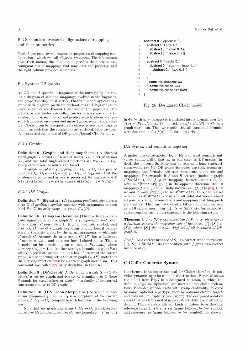
30 Kacper Bąk et al.
B.3 Semantic universe: Configurations of mappingsand their properties
Table 3 presents several important properties of mapping con-figurations, which we call diagram predicates. The left columngives their names, the middle one specifies their arities, i.e.,configurations of mappings that may have the property, andthe right column provides semantics.
B.4 Syntax: DP-graphs
An OO model specifies a fragment of the universe by describ-ing a diagram of sets and mappings involved in the fragment,and properties they must satisfy. That is, a model appears as agraph with diagram predicate declarations (a DP-graph) thatdescribe properties. Formal CDs used in the paper are DP-graphs, whose nodes are called classes, arrows are maps (=unidirectional associations), and predicate declarations are con-straints imposed on classes and maps. Hence, semantics of a for-mal CDs is given by interpreting its classes as sets, and maps asmappings such that the constraints are satisfied. Here we spec-ify syntax and semantics of DP-graphs/formal CDs formally.
B.4.1 Graphs
Definition 6 (Graphs and their moprhisms.) A (directedmulti)graph G consists of a set of nodes GN , a set of arrowsGA, and two total single-valued functions src, trg:GA → GNgiving each arrow its source and target.
A graph morphism (mapping) f : G1 → G2 is a pair offunctions fN : G1N → G2N and fA: G1A → G2A such that theincidence of nodes and arrows is preserved: for any arrow a ∈G1A, src(fA(a)) = fN (src(a)) and trg(fA(a)) = fN (trg(a)).
B.4.2 DP-Graphs
Definition 7 (Signature.) A (diagram predicate) signature isa set Σ of predicate symbols together with assignment to eachlabel P ∈ Σ its arity shape – a graph Gar(P ).
Definition 8 ((Diagram) formulas.) Given a diagram pred-icate signature Σ and a graph G, a (diagram) formula overG is a pair (P, args) with P ∈ Σ a predicate symbol, andargs : Gar(P ) → G a graph morphism binding formal param-eters in the arity graph by the actual arguments — elementsof graph G. Assume the arity graph Gar(P ) has a finite setof arrows α1...αn, and does not have isolated nodes. Then aformula can be encoded by an expression P (a1...an) whereai = args(αi), i = 1..n. In other words, a formula is a pair (P,a)with P a predicate symbol and a a bag of arrows of the carriergraph, whose indexing set is the arity graph Gar(P ) (note thatthe indexing function must be a correct graph morphism – thisconstraint was called [ad], arity discipline, in Sect. 6.1.3.
Definition 9 (DP-Graph) A DP-graph is a pair S = (G,Φ)with G a carrier graph, and Φ a set of formulas over G (hereS stands for specification, or sketch — a family of categoricalconstructs similar to DP-graphs).
Definition 10 (DP-Graph Morphisms.) A DP-graph mor-phism (mapping) f : S1 → S2 is a morphism of the carriergraphs, f : G1 → G2, compatible with formulas in the followingway.
Note that any graph morphism f : G1 → G2 translates for-mulas overG1 into formulas overG2: any formula φ = P (a1..an)
1 abstract 0..∗ options 0..∗ {2 abstract 1..1 size 1..1 {3 abstract 0..∗ small 0..1 {}4 abstract 0..∗ large 0..1 {}5 }6 abstract 0..∗ cache 0..1 {7 abstract 0..∗ size→ integer 1..1 {8 abstract 0..∗ fixed 0..1 {}9 }
10 }11 [ some this.size.small &&12 some this.cache =⇒13 some this.cache.size.fixed ]14 }
Fig. 26: Desugared Clafer model.
in Φ1 (with ai = αi.args) is translated into a formula over G2,f(φ) = P (a1.f, ..., an.f)—indeed, args.f : Gar(P ) → G2 is agraph morphism. Then we require that all translated formulaswere declared in Φ2: f(φ) ∈ Φ2 for all φ ∈ Φ1.
B.5 Syntax and semantics together
A major idea of categorical logic [10] is to treat semantic uni-verses syntactically, that is, in our case, as DP-graphs. In-deed, the universe SetMap can be seen as a huge (categori-cians would say big) DP-graph: its nodes are sets, arrows aremappings, and formulas are true statements about sets andmappings. For example, if A and B are sets (nodes in graphΓ [SetMap]), and f , g are mappings between them (i.e., ar-rows in Γ [SetMap]) going in the opposite direction, then, ifmappings f and g are mutually inverse, i.e., (f, g) |= [inv], thenwe add formula [inv](f, g) to set Φ[SetMap]. Thus, the big setof formulas Φ[SetMap] consists of all valid statements aboutall possible configurations of sets and mappings matching pred-icate arities. Then an instance of a DP-graph S can be seenas a DP-graph morphism J..K : S → SetMap. An immediateconsequence of such an arrangement is the following result:
Theorem 3 Any DP-graph morphism f : S1 → S2 gives rise toa function between the respective sets of instances, JfK : JS1K←JS2K, where JSiK denotes the (big) set of all instances of DP-graph Si.
Proof . As a correct instance of S2 is a correct graph morphism,J..K : S2 → SetMap, its composition with f gives us a correctinstance of S1.
C Clafer Concrete Syntax
Conciseness is an important goal for Clafer; therefore, it pro-vides syntactic sugar for common constructions. Figure 26 showsthe model from Fig. 7 in a desugared notation, in which thedefaults (e.g., multiplicities) are inserted into clafer declara-tions. Each declaration starts with group cardinality, followedby name, optional supertype, then by optional clafer’s target,and ends with multiplicity (see Fig. 27). The desugared notationshows that all clafers nested in an abstract clafer are abstract bydefault. There are also different kinds of clafers: basic (have noreference target), reference set (name followed by ’→’ symbol,and reference bag (name followed by ’�’ symbol); not shown.

Clafer: Unifying Class and Feature Modeling 31
〈Clafer〉 ⇒ 〈Abs〉 〈GCard〉 string 〈Super〉 〈Target〉 〈Card〉〈Elements〉〈Abs〉 ⇒ | abstract〈Elements〉 ⇒ {〈ElList〉} 〈ElList〉 ⇒ | 〈Element〉 〈ElList〉〈Element〉 ⇒ 〈Clafer〉 | 〈Constraint〉〈Super〉 ⇒ | : string〈Target〉 ⇒ | 〈Kind〉 string〈Kind〉 ⇒ → | �〈GCard〉 ⇒ | xor | or | mux | opt | 〈NCard〉〈Card〉 ⇒ | ? | + | * | 〈NCard〉〈NCard〉 ⇒ integer .. ExInteger〈ExInteger〉 ⇒ * | integer
Fig. 27: BNF grammar of Clafer (no constraints).
Clafer multiplicity is given by an interval m..n. Clafer pro-vides syntactic sugar similar to syntax of regular expressions:? (optional) denotes 0..1; * denotes 0..∗; and + denotes 1..∗. Bydefault, clafers have multiplicity 1..1.
Group cardinality is given by an interval m..n, with thesame restrictions on m and n as for multiplicities, or by a key-word: xor denotes 1..1; or denotes 1..∗; opt denotes 0..∗; and muxdenotes 0..1; further, each of the keywords makes children op-tional by default. For example, xor on size (line 2) states thatonly one child instance of either small or large is allowed. Noexplicit group cardinality stands for 0..∗, except when it is in-herited from clafers supertype.
D Clafer Constraint Language
The Clafer constraint language is essentially borrowed from Al-loy [41]. The two most significant differences are name resolu-tion rules and the default some quantifier before clafer names.Both developments contribute to conciseness of the constraintsdefined over hierarchical models. Constraints are logical expres-sions composed of terms and logical operators. Terms either re-late values (integers, strings) or are navigational expressions.The value of navigational expression is always a set, thereforeeach expression must be preceded by a quantifier, such as no(requires set to be empty), one (requires set to have one ele-ment), lone (requires set to have at most one element), or some(requires the set to be non-empty). Lack of explicit quantifier(Fig. 7) stands for some (Fig. 26).
Although the constraints are specified over Clafer models,we define their semantics over Class Diagrams (our semanticdomain). A formal class diagram of Clafer model is composedof classes, maps, and constraints. An instance of class diagramis an object diagram that is composed of objects and links;it must satisfy constraints defined over CD. Each constraintis defined in context of a class. The context corresponds todefining constraints nested under clafers, because in a CS thehead class represents the clafer. If in a Clafer model constraint isdefined at top-level, then in the corresponding MCS and CD it isdefined in the context of synthetic root. The constraint languageused in Clafer allows one to define new diagram predicates ofshapes spanning several Clafer shapes and whose semantics isexpressible in first-order logic.
D.1 Grammar
Figure 28 shows grammar of the core constraint language. Thefull constraint language has additional syntactic sugar, but anyconstraint may be desugared to the core constraint language. Inthe first production in Fig. 28 var represents variables bound byquantifiers. In the production with binary operators, ⊕ is one
〈Exp〉 ⇒all var : 〈SetExp〉 | 〈Exp〉 universal quantification| 〈Exp〉 && 〈Exp〉 conjunction| ! 〈Exp〉 negation| 〈Exp〉 ⊕ 〈Exp〉 binary operators| # 〈Exp〉 set cardinality| 〈SetExp〉 set expression〈SetExp〉 ⇒〈SetExp〉 ⊗ 〈SetExp〉 set operators| 〈SetExp〉 . 〈SetExp〉 relational join| Name reserved/map name
Fig. 28: BNF grammar of core Clafer constraints
of <,=,+,− (logical comparison, equality, addition, and sub-traction, respectively). In the production with set operators, ⊗is one of ++,−−,&, in (set union, difference, intersection, andsubsetting, respectively). The last production Name representsnames of head maps that correspond to clafer names, or is oneof reserved names. When Names form a sequence n1.n2 . . . nm,we call such as an expression a navigation. The dot betweennames indicates relational join.
D.2 Name Resolution Rules
Name resolution rules disambiguate names of clafers used inconstraints. The rules are needed as clafer names may repeatin Clafer model. The rules are applied during compilation ofClafer model to MCS; thus MCS and CD have all names prop-erly resolved. The rules are similar to CVL rules [39], as thelatter were inspired by Clafer. A name is resolved in the con-text of a clafer (top-level constraints are defined in the contextof synthetic root) as follows:
1. Reserved names. Check if it is a special name: such asparent, dref, and this. The latter indicates object for whichthe constraint is evaluated. Further, primitive domains alsouse reserved names, int for integers, and string for strings.
2. Binding. Check if name is introduced by a local variable(used in constraints with quantifiers).
3. Descendants. Look up the name in descendant clafers of thecontext clafer in breadth-first search manner. If a clafer hassupertype, take into account inherited clafers.
4. Targets. Similar to the previous step but additionally takeinto account clafers reachable via references.
5. Ancestors. Search in the ancestors clafers starting from theparent clafer of the context and up. For each ancestor, lookup the name using the rules Descendants and, if necessary,Targets.
6. Top level. Search in other top-level clafers. For each claferapply rules Descendants and, if necessary, Targets.
7. Error. If the name cannot be resolved or is ambiguouswithin a single step, the constraint is not well-formed andan error is reported.
For navigations (expressions of the form n1.n2 . . . nm) thename resolution rules are applied to resolve n1 first. Once itis resolved, subsequent clafers (n2.n3 . . . nm) are resolved byapplying only rules Reserved names, Descendants, and Error.Note that n1 becomes the context clafer for resolving n2, andn2 becomes the context for n3, etc. A fully resolved name is anavigation that starts with this, i.e., is of the form this.c2 . . . cm.

32 Kacper Bąk et al.
D.3 Type Rules
The type system is specified in a series of formal rules.
statementA
statementB
The above rule says that if A holds, then B follows.
D.3.1 Expressions
Universal quantification. In the rule below the environment envis extended by specifying that the type of var is SetExp.
env, var :: SetExp ` Exp :: Booleanenv ` all var : SetExp | Exp :: Boolean
Conjunction.env ` Exp1 :: Boolean env ` Exp2 :: Boolean
env ` Exp1 && Exp2 :: Boolean
Negation.env ` Exp :: Booleanenv ` !Exp :: Boolean
Comparison.env ` Exp1 :: τ env ` Exp2 :: τenv ` Exp1 ⊕ Exp2 :: Boolean
,
where ⊕ ∈ {<,=}.Arithmetic operator.
env ` Exp1 :: τ env ` Exp2 :: τenv ` Exp1 + Exp2 :: τ
, where ⊕ ∈ {+,−}.
Set cardinality.env ` Exp :: τ
env ` #Exp :: IntegerSet expression. env ` Exp :: τ
D.3.2 Set Expressions
Set operators.env ` Exp1 :: τ env ` Exp2 :: τ
env ` Exp1 ++ Exp2 :: τ,
where ⊕ ∈ {++,−−,&}.
Subsetting.env ` Exp1 :: τ env ` Exp2 :: τenv ` Exp1 in Exp2 :: Boolean
Relational join.env ` Exp1 :: τ × υ env ` Exp2 :: υ × φ
env ` Exp1.Exp2 :: τ × φenv ` Exp1 :: τ env ` Exp2 :: τ × υ
env ` Exp1.Exp2 :: υReserved/map name.
env ` this :: τenv ` Name :: τ × υ
D.4 Semantics
The semantics assumes that: 1) navigation paths have alreadybeen resolved to specific clafers (head classes), and 2) all expres-sions are correctly typed. A constraint is specified in the contextof a class, and is evaluated in the context of each instance (ob-ject) of that class. We call the latter context an environment.For an object o we initialize environment to be env = {this 7→ o}
Env = Var→ ValueValue = P(Object) ∪ P(Link)Environment maps variables to values, which are either sets
of objects or links. Note that a single object would be repre-sented as a singleton set.
A constraint is a Boolean-valued expression. The semanticsuses two interpretation functions:
JKE : Exp→ Env→ Boolean ∪ P(Object)JKS : SetExp→ Env→ ValueThe former function interprets abstract syntax elements of
expressions for a given environment and evaluates to a Booleanvalue or a set of objects. A set of objects is always a singleton.In particular, values of primitive domains (e.g., integer) are en-coded as singletons. Analogically, the latter function interpretsset expressions, which are either sets of objects or links.
D.4.1 Semantics of Expressions
Universal quantification. For universal quantification the ex-pression Exp has to hold for each instance of SetExp. It isdone by extending the environment with a mapping fromfrom var to an instance.Jall var : SetExp | ExpKE env=
∧{JExpKE (env⊕ var 7→ v)|v ∈
JSetExpKS env}Conjunction.
JExp1 && Exp2KE env= JExp1KE env∧ JExp2KE envNegation. J!ExpKE env= ¬ JExpKE envLess than. JExp1 < Exp2KE env= JExp1KE env< JExp2KE envEquality. JExp1 = Exp2KE env= (JExp1KE env= JExp2KE env)Subsetting.
JExp1 in Exp2KE env= JExp1KE env⊆ JExp2KE envAddition. JExp1 + Exp2KE env= JExp1KE env+ JExp2KE envSubtraction. JExp1 - Exp2KE env= JExp1KE env− JExp2KE envSet cardinality. J#ExpKE env= | JExpKE env|Set expression. Although set expressions are also expressions,
they must be quantified to evaluate to a Boolean value.JSetExpKE env= JSetExpKS env
D.4.2 Semantics of Set Expressions
Union. JExp1 ++ Exp2KS env= JExp1KS env∪ JExp2KE envDifference. JExp1 – – Exp2KS env= JExp1KS env\ JExp2KE envIntersection. JExp1 & Exp2KS env= JExp1KS env∩ JExp2KE envRelational join. Relational join (the dot operator) joins two re-
lations. In our formal CDs all navigational expressions startwith the this keyword, which is then followed by names ofmaps (clafer names): Name. The this keyword indicates anobject; it can be viewed as a unary relation. Furthermore,all other relations are binary, thus the final result of eachnavigation expression is always a set of objects. If any ofthe components of the navigational expression evaluates toan empty set, the final result is also an empty set.JExp1.Exp2KS env={(x, z)|∃y((x, y) ∈JExp1KSenv ∧ (y, z) ∈JExp2KSenv)}
Reserved/map name. It refers to names of maps in formal CD.JNameKS env= env(Name)
E MCS Constraints
Each Multi-Clafer Shape is only valid if it satisfies incidenceconstraints (defined in Tab. 5), clafer kind/shape discipline con-straints (defined in Tab. 7), clafer cojoining constraints (definedin Tab. 6), and naming discipline constraints (defined in Tab. 8).

Clafer: Unifying Class and Feature Modeling 33
Description ConstraintsThe map head_map goes from class (role)source_class to class head_class. Analogicalconstraints hold for the maps parent_map,dref_map, and target_map.
this.head_map.so = this.source_classthis.head_map.ta = this.head_class
Table 5: Incidence constraints in the context of Clafer, which the MCS meta-model in Fig. 23 must satisfy
Description ConstraintsThe class source_class of given CS is a classhead_class of the parent CS. Analogical con-straints hold for cojoining CS with the CS of itstarget.
this.source_class = this.parent.head_classthis.target_class = this.target.head_class
In case of subclassing between two clafers, thereexists an inclusion between the head classes ofthe two CSs. Analogical constraints hold for mapssupers and supert if the corresponding source andtarget classes exist in both CSs.
this.super 6= ⊥ =⇒this.superh.so = this.head_classthis.superh.ta = this.super.head_class
Table 6: Clafer cojoining MCS constraints in the context of Clafer, which the MCS meta-model in Fig. 23 mustsatisfy
Description Constraints
The CS of Sing has only the class Sing as headand does not participate in inheritance.
this ∈ Sing =⇒this.source_class = ⊥this.target_class = ⊥
this.super = ⊥
The CS of Dom is a basic clafer whose parent isSing.
this ∈ Dom =⇒this.source_class = Sing
this.target_class = ⊥this.super = ⊥
Basic clafers have a source_class but no tar-get_class. Analogical constraints apply to refer-ence clafers.
this ∈ BasicClafer =⇒this.source_class 6= ⊥this.target_class = ⊥
Top-level clafers, that are not a synthetic root,are abstract.
this.parent = ⊥ ∧ this 6= Sing =⇒this.abstract = true
Table 7: Clafer kind constraints in the context of Clafer, which the MCS meta-model in Fig. 23 must satisfy
Description ConstraintsThe map head has the same name as the classhead. this.head_map.label = this.head_class.label
The map parent is named “parent”. Analogicalconstraints holds for the map dref.
this.parent_map.label = "parent"
The map target (if defined) has name derivedfrom the name of the class head by concatenatingthe name with *.
this.target_map.label =concat(this.head_map.label, *)
There is one distinguished element of Stringnamed “Sing”. Analogical constraints hold forother predefined clafers, such as “int” and “string”.
this ∈ Sing ⇐⇒ this.head_class.label = "Sing"
Table 8: Naming constraints in the context of Clafer, which the operation Compile must satisfy

34 Kacper Bąk et al.
F Full Telematics Model
Below is the running example of telematics system modeled inClafer.
abstract optionsxor size
small ?large ?
cache ?size→ integer
fixed ?[ small && cache =⇒ fixed ]
abstract compversion→ integer
abstract ECU : comp
abstract display : compserver→ ECU‘options // shorthand for options : options[ version ≥ server.version ]
abstract plaECU : ECUplaDisplay : display 1..2
[ no cache ][ server = parent ]
ECU1 : plaECU
ECU2 : plaECU ?master→ ECU1
// feature model for the specific PL
telematicsxor channel
single ?dual ?
extraDisplay ?
xor sizesmall ?large ?
[ dual⇔ ECU2extraDisplay⇔#ECU1.plaDisplay = 2extraDisplay⇔ (ECU2 =⇒ #ECU2.plaDisplay = 2)large⇔ !plaECU.plaDisplay.options.size.smallsmall⇔ !plaECU.plaDisplay.options.size.large ]
[ dualextraDisplaytelematics.size.large ]