cm-l1-g-70-995003 rev c
TRANSCRIPT
DRAWING/DOCUMENT STATUS: Final for Reference
C 2007.09.18 Change of Unit ID from 459341723 Loenne Rost Duehrkop B 2007.08.23 Attachment 1to 14 included Loenne Rost Duehrkop A 2007.07.10 First issue Loenne Rost Schobert
Rev. DATE DESCRIPTION Bearb. Coord.
Geprüft Checked APPD.
PROJECT :
CAMAU 2 750MW COMBINED CYCLE POWER PLANT OWNER OWNER’S ENGINEER :
PETRO VIETNAM CPMB
CONTRACTOR : CONTRACTOR’S ENGINEER :
LILAMA CORPORATION FICHTNER
SUBCONTRACTOR’S NAME : SUBCONTRACTOR’S SUPPLIER :
s POWER GENERATION
DRAWING TITLE :
Steam Blow Concept PKZ UAS Contents Code Reg. No. UNID
VIT800 DN02 9800 995003 460265919 Ursprung/Original Ursprung-Nr./Original-No. Urspr.-PKZ-Nr.
Orig.-PC
Projekt/Project PKZ/PC
CA MAU 2 750MW CCPP VIT800 Datum
Date Name Maßstab
Scale N/A A4 UA/DCC Type DN02
gezeich. Drawn 2007-07-10 Loenne Benennung/Title Inhaltskennzeichen
Contents Code bearb. Coord. 2007-07-10 Rost
geprüft Checked 2007-07-10 Schobert
9800 Abtlg. Dept. EC1 sgd.
Steam Blow Concept Zähl.-Nr. Reg.-No. 995003
Dienstst./Dept. UNID Index/Rev. Version
s AG POWER GENERATION EC1 460265919 C
Blatt-Nr./Page-No.
CM2-L1-G-.70-995003 Erstellt mit/designed with
Ersatz für Supersedes

Siemens AG . Power Generation (PG) Inbetriebsetzung
Dampfausblasekonzept
Steam Blow Concept Seitenzahl: No. of Pages
17 Anlagen:Appendices
16
Ibs-Kennzeichen
Ca Mau II SCC5-4000F (2+1) VIT800 DN02 B-HA / LB-01 Kraftwerk/Power Plant Block/Unit KW-Nr./Plant Code UA Inhaltskennzeichen/Contents Code Zähl-Nr./Reg. No.
Handhabung/Handling: Restriktiv//Restricted
System/Komponente: System/Component
Cleaning of steam systems
Anweisungstitel: Instruction Title
- Steam Blow Concept - Steam blow of HRSG’s and steam pipes
Table of Contents 1 Purpose 6 Start-up, steam blow steps and steam blow conditions 2 General description 7 Scope of measurement 3 Preparation tasks 8 Performance criteria 4 Precautions 9 Attachments 5 Operating design
*) Nicht zutreffendes streichen *) Delete as appropriate
Erstellt Prepared by
Erstellt/Geprüft*) Prepared/Verified by
Geprüft/Freigeg.*) Verified/Released by
Geprüft/Freigeg.*) Verified/Released by
Dienststelle Department
EC62 EC62 ÊC61 E-CM2
Name Name
Lönne Rost Unger Schobert
Datum Date
2007-05-11 2007-06-04 2007-07-09 2007-07-02
Unterschrift Signature
gez gez gez gez
*) Nicht zutreffendes streichen *) Delete as appropriate
Geprüft/Freigeg.*) Verified/Released by
Geprüft/Freigeg.*) Verified/Released by
Geprüft/Freigeg.*) Verified/Released by
Geprüft/Freigeg.*) Verified/Released by
Dienststelle Department
Name Name
Datum Date
Unterschrift Signature
Geändert: modified by
c b a Rev. Name/Kurzzeichen Dienststelle/Firma Datum Fachabteilung, Ibs-Leitung, Projektleitung Index Name/Signature Department/Company Date Techn. Department, Com. Management, Project Management
Verteiler: Copies to
E272, EE15, EE16, EC1, EC61
Commissioning L:\15_Plant_Cleaning_Chemistry\03_Cleaning\03_Steam Blow\03_Actual Projects\Ca Mau II\Steam Blow Procedure\Comm-Instr_SteamblowCaMauII_final.doc

Kraftwerk: Power Plant
Ca Mau II SCC5-4000F (2+1)
BKW-Kennzeichen: VIT 800 BKW-Code:
Seite: Page
2
Dampfausblasekonzept Steam Blow Concept
Steam blow of HRSG’s and steam pipes
Siemens AG . Power Generation (PG) Inbetriebsetzung
1. Purpose
The purpose of this procedure is to describe the preparation tasks, precautions and operation steps involved in the steam blow cleaning of the Heat Recovery Steam Generators (HRSG’s) and associated steam pipes. Prior to initial operation of the steam turbine (ST) the steam blow process serves to clear the steam piping of foreign material which may remain in components or systems after chemical cleaning. The steam used for steam blows will be provided by the HRSG’s and for the cleaning of the auxiliary steam system by the auxiliary steam generator. The required cleaning criteria regarding the removal of dirt and debris shall be achieved prior to the initial steam supply to the steam turbine. 2. General description Prior to the steam blow process a chemical cleaning of the HRSG’s and associated steam pipes will be carried out. The chemical cleaning of the HRSG’s, the HP-, IP- and LP-steam pipes will remove all oxide products (e.g. mill scale, welding slag) as well as all organic materials. Metallic parts (e.g. weld rods, steel grid etc.) should not be in the boiler components or steam pipes, nevertheless the steam systems shall be cleaned from remaining particles during steam blows. Prior to the steam blows, the steam turbine seal steam supply system will be cleaned by means of air blows (to be performed by steam turbine construction department) and the auxiliary steam piping shall be blown by means of steam provided by the auxiliary steam generator. During the steam blows of the auxiliary steam system the steam will be vented to the atmosphere. Seal steam supply to the steam turbine is not allowed before the performance of these service blows (see Remark) !!! Remark: A service blow is defined as a steam blow without using targets for evaluation of cleaning criteria. The system will be blown until the steam plume appears visually clean at the steam exit to the atmosphere. The boiler steam systems as : • HRSG’s, HP- , IP- and LP-superheaters and re-heaters (RH)
• HP-steam pipes
• Cold reheat steam pipes (CRH)
• Hot reheat steam pipes (HRH)
• IP-steam pipes
• LP-steam pipes
shall be cleaned during atmospheric blow out by means of steam generated during operation of the gas turbine(s) (GT(s)). In order to achieve an effective steam blow in the HP-systems during the steam blow steps No.5 and No.6, the steam will be led firstly through the temporary HP-emergency stop valve inserts of 20MAA11AA051 and 20MAA21AA051 via temporary piping and silencer to the atmosphere (see Attachments No.7 & No.8). During the steam blow steps No.7 and No.9 the cleaned HP-steam shall be led through the original HP-bypass stations into the reheat systems, through the IP-emergency stop valve inserts of 20MAB11AA051 and 20MAB21AA051 and via temporary piping and silencer to the atmosphere (see Attachments No.9 & 11). Ensuing the HP-steam shall be led during the steam blow steps No.8 and No.10 through the temporary HP-emergency stop valve inserts of 20MAA11AA051 & 20MAA21AA051, through temporary piping into the cold reheat system, through the IP-emergency stop valve inserts of 20MAB11AA051 & 20MAB21AA051 and via temporary piping and silencer to the atmosphere (see Attachments No.10 & 12). In order to clean the common HP-, CRH- and HRH-steam pipes both HRSG’s will be operated during steam blow step No.11. During this step the steam is routed through the HP-emergency stop valve inserts of 20MAA11AA051 & 20MAA21AA051, through the reheat systems, through the IP-emergency stop valve inserts of 20MAB11AA051 & 20MAB21AA051 and via temporary piping and silencer to the atmosphere (see Attachment No.13). The LP-steam systems will be cleaned during steam blow step No.12. The LP-steam shall be exhausted through the LP-shut off damper connection (20MAC45AA051 temporarily removed) via temporary piping and
Commissioning L:\15_Plant_Cleaning_Chemistry\03_Cleaning\03_Steam Blow\03_Actual Projects\Ca Mau II\Steam Blow Procedure\Comm-Instr_SteamblowCaMauII_final.doc
Kraftwerk: Power Plant
Ca Mau II SCC5-4000F (2+1)
BKW-Kennzeichen: VIT 800 BKW-Code:
Seite: Page
3
Dampfausblasekonzept Steam Blow Concept
Steam blow of HRSG’s and steam pipes
Siemens AG . Power Generation (PG) Inbetriebsetzung
silencer to the atmosphere (see Attachments No.14). During this steam blow step both HRSG’s will be operated in parallel in order to clean the boiler related LP-systems as well as the LP-common pipe section.
The LP-system steam blow allow to save demineralised water and shortens the cleaning period due to an operation of the HP- and IP-system in a bypass mode, that means HP-steam shall be led via the HP-bypass station(s) and the IP-steam via the IP-bypass station(s) into the condenser. For a proper cleaning by means of steam blow a Cleaning Force Ratio (CFR) or so called “disturbance factor” of 1,2 at all sections should be achieved. That means the cleaning will be accomplished by developing a steam flow in the piping with a mass-velocity head equal or greater than that which will occur in each steam line during normal full load operation. The Cleaning Force Ratio (CFR) is defined as follows:
CFRmm
b b
o o
=⋅⋅
2
2
υυ
mb = mass flow (blow)
υb = specific. volume (blow)
mo = mass flow (max. operating condition)
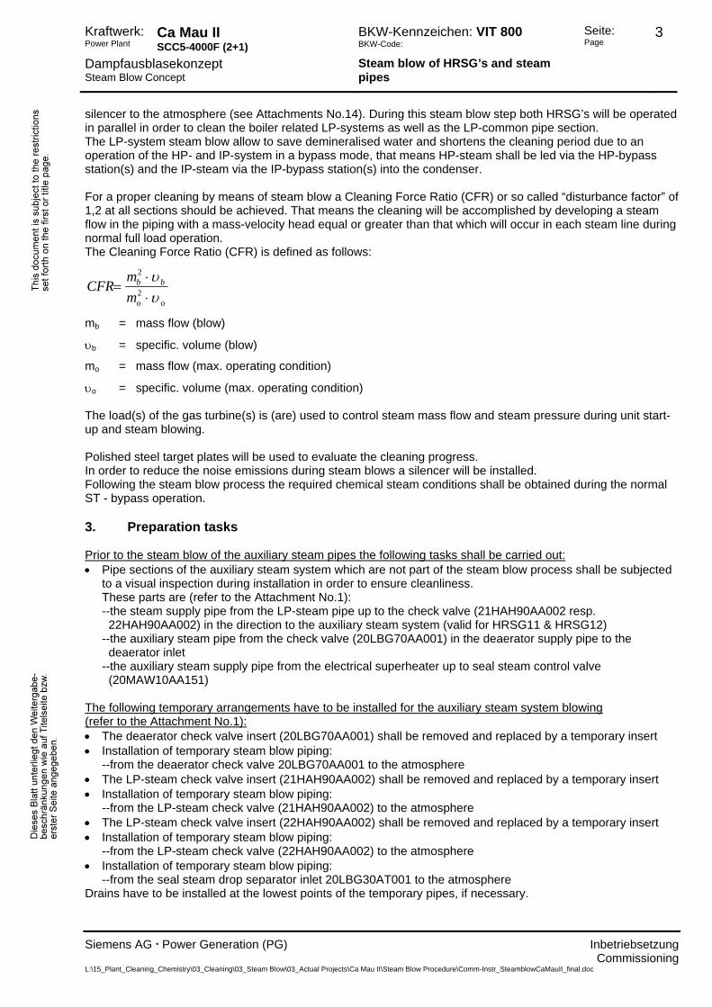
υo = specific. volume (max. operating condition) The load(s) of the gas turbine(s) is (are) used to control steam mass flow and steam pressure during unit start-up and steam blowing. Polished steel target plates will be used to evaluate the cleaning progress. In order to reduce the noise emissions during steam blows a silencer will be installed. Following the steam blow process the required chemical steam conditions shall be obtained during the normal ST - bypass operation. 3. Preparation tasks Prior to the steam blow of the auxiliary steam pipes the following tasks shall be carried out: • Pipe sections of the auxiliary steam system which are not part of the steam blow process shall be subjected
to a visual inspection during installation in order to ensure cleanliness. These parts are (refer to the Attachment No.1): --the steam supply pipe from the LP-steam pipe up to the check valve (21HAH90AA002 resp. 22HAH90AA002) in the direction to the auxiliary steam system (valid for HRSG11 & HRSG12) --the auxiliary steam pipe from the check valve (20LBG70AA001) in the deaerator supply pipe to the deaerator inlet --the auxiliary steam supply pipe from the electrical superheater up to seal steam control valve (20MAW10AA151)
The following temporary arrangements have to be installed for the auxiliary steam system blowing (refer to the Attachment No.1): • The deaerator check valve insert (20LBG70AA001) shall be removed and replaced by a temporary insert • Installation of temporary steam blow piping:
--from the deaerator check valve 20LBG70AA001 to the atmosphere • The LP-steam check valve insert (21HAH90AA002) shall be removed and replaced by a temporary insert • Installation of temporary steam blow piping:
--from the LP-steam check valve (21HAH90AA002) to the atmosphere • The LP-steam check valve insert (22HAH90AA002) shall be removed and replaced by a temporary insert • Installation of temporary steam blow piping:
--from the LP-steam check valve (22HAH90AA002) to the atmosphere • Installation of temporary steam blow piping:
--from the seal steam drop separator inlet 20LBG30AT001 to the atmosphere Drains have to be installed at the lowest points of the temporary pipes, if necessary.
Commissioning L:\15_Plant_Cleaning_Chemistry\03_Cleaning\03_Steam Blow\03_Actual Projects\Ca Mau II\Steam Blow Procedure\Comm-Instr_SteamblowCaMauII_final.doc
Kraftwerk: Power Plant
Ca Mau II SCC5-4000F (2+1)
BKW-Kennzeichen: VIT 800 BKW-Code:
Seite: Page
4
Dampfausblasekonzept Steam Blow Concept
Steam blow of HRSG’s and steam pipes
Siemens AG . Power Generation (PG) Inbetriebsetzung
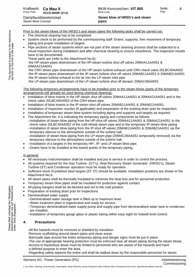
Prior to the steam blows of the HRSG’s and steam pipes the following tasks shall be carried out:
• The chemical cleaning has to be completed. • System check to be performed by the commissioning staff: Drains, supports, free movement of temporary
piping and proper installation of targets. • Pipe sections of steam systems which are not part of the steam cleaning process shall be subjected to a
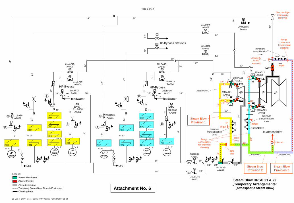
visual inspection during installation and after chemical cleaning to ensure cleanliness. The inspection results have to be documented. These parts are (refer to the Attachment No.6): -the HP-steam pipes downstream of the HP-steam turbine shut off valves 20MAA11AA051 & 20MAA21AA051 -the CRH steam pipe downstream of the HP-steam turbine exhaust until CRH check valve 20LBC40AA052 -the IP-steam pipes downstream of the IP-steam turbine shut off valves 20MAB11AA051 & 20MAB21AA051 -the IP-steam turbine exhaust to the tie into the LP-steam inlet pipe -the LP-steam pipe downstream of the LP-steam turbine shut off damper 20MAC45AA051
The following temporary arrangements have to be installed prior to the steam blows (parts of the temporary arrangements will already be used during chemical cleaning): • Installation of blow inserts in the HP-steam shut off valves 20MAA11AA051 & 20MAA21AA051 and in the
check valve 20LBC40AA052 of the CRH steam pipe. • Installation of blow inserts in the IP-steam shut off valves 20MAB11AA051 & 20MAB21AA051. • Installation of inspection nozzles (if applicable) and preparation of the existing drain pots for inspection. • Installation of temporary steam blow system including piping and supports and targets as required. • The Attachment No. 6 is indicating the temporary piping and components as follows: --Installation of steam blow piping from the HP-shut off valves 20MAA11AA051 & 20MAA21AA051 to the check valve 20LBC40AA052 of the cold reheat steam pipe and to the temporary IP-steam blow piping. --Installation of steam blow piping from the IP-shut off valves 20MAB11AA051 & 20MAB21AA051 via the temporary silencer to the atmosphere outside of the turbine hall. --Installation of steam blow piping from the LP-steam pipe (20MAC45AA051 temporarily removed) via the temporary silencer to the atmosphere outside of the turbine hall. • --Installation of a targets in the temporary HP-, IP- and LP-steam blow pipe. • --Drains have to be installed at the lowest points of the temporary piping. In general: • All necessary instrumentation shall be installed and put in service in order to control the process. • All systems required for the Gas Turbine- (GT’s), Heat Recovery Steam Generator- (HRSG’s), Steam
Turbine-(ST) and Condenser operation must be ready for operation. • Sufficient stock of polished steel targets (ST 37) should be available. Installation positions are shown in the
Attachment No.6. • All steam pipes shall be thermally insulated to minimise the heat loss and for personnel protection. • Temporary steam blow pipes shall be insulated for protection against contact. • All piping hangers shall be de-blocked and set to the cold position. • Preparation of existing drain pots for inspections • Demineralised water supply
--Demineralised water storage tank is filled up to maximum level. --Water treatment plant is regenerated and ready for service. --Temporary demineralised water supply pump and supply pipe from demineralised water tank to condenser are installed. --Installation of temporary gauge glass or plastic tubing within easy sight for hotwell level control.
4. Precautions -All fire hazards must be removed or shielded by insulation. -Remove scaffolding around steam pipes and clean areas. -Barricade tape around the entire temporary piping and danger signs must be put in place. -The use of appropriate hearing protection must be enforced near all steam piping during the steam blows. -Access to hazardous areas must be limited to personnel who are aware of the hazards and have a defined purpose to enter the area. -Regarding safety aspects the entire unit shall be walked down by the responsible personnel for steam
Commissioning L:\15_Plant_Cleaning_Chemistry\03_Cleaning\03_Steam Blow\03_Actual Projects\Ca Mau II\Steam Blow Procedure\Comm-Instr_SteamblowCaMauII_final.doc

Kraftwerk: Power Plant
Ca Mau II SCC5-4000F (2+1)
BKW-Kennzeichen: VIT 800 BKW-Code:
Seite: Page
5
Dampfausblasekonzept Steam Blow Concept
Steam blow of HRSG’s and steam pipes
Siemens AG . Power Generation (PG) Inbetriebsetzung
blow co-ordination. Any additional requirements will be completed prior to the start of the steam blow
process. 4.1 Precautionary measures in the DCS-System • If the pressure in the HP-steam pipe(s) rises above 25 bara the load of the gas turbine(s) will be reduced.1 • The pressure setpoint of the HP-bypass station shall be reduced to 27 bar in order to avoid overpressure in the temporary HP-steam blow piping Provision 1.1
• If the boiler outlet HP-steam temperature (downstream water injection) exceeds 420°C the load of the gas turbine(s) will be reduced (Due to design limits of temporary piping and equipment).1 (temporary HP-steam blow pipe: max. allowable operating pressure 37 bara / temperature 400°C)
• In case of a HP-bypass station blockage during the steam blow operation, the gas turbine will be tripped (valid for steam blow step No.7 and No.9). • In case of a HP- and/or IP- bypass station blockage during the steam blow operation, the gas turbines will be tripped (valid for steam blow step No.12). • If the pressure in the condenser rises above 600 mbar abs the IP-bypass stations and the GT’s will be tripped (valid for steam blow step No. 12).
1 Temporary change in the DCS-logic for steam blow step No. 5, 6, 8, 10 and 11 ! Attention !!!: For the steam blow steps No. 7, No. 9 and No.12 the changes in the DCS-logic regarding the HP-pressure, HP-temperature and HP-bypass setpoint will be re-adjusted to the original settings !
4.2 Precautionary measures during steam blow operation
• The steam temperatures can be controlled by water injection controllers and / or with the gas
turbine exhaust gas temperature. • Since mechanical carry over cannot be excluded at all times during this kind of operation, it is
essential that only volatile treatment (e.g. ammonia) is used. Hence solid alkalinisation (e.g. Na3PO4) shall not be used during steam blow operation.
5 Design 5.1 Design limits of temporary steam blow arrangements For the steam blows of HRSG’s and associated steam pipes:
Temporary steam blow equipment Pressure
(barg) Temperature
(°C) HP- Shut off valve inserts (2 pieces) 50 540 IP- Shut off valve inserts (2 pieces) 50 540 Check valve insert in cold reheat (1 piece) 39 400 Temporary piping for HP-steam system blow (Provision No.1) 36 400 Temporary piping for IP-steam system blow (Provision No.2) 10 400 Temporary piping for LP-steam system blow (Provision No.3) 10 400 Target plate for 1 location in Provision No.1 36 400 Target plates for 2 locations in Provisions No.2 and No.3 10 400 Silencer (1 piece) for HP-, IP- and LP-steam blow 2 400
Commissioning L:\15_Plant_Cleaning_Chemistry\03_Cleaning\03_Steam Blow\03_Actual Projects\Ca Mau II\Steam Blow Procedure\Comm-Instr_SteamblowCaMauII_final.doc

Kraftwerk: Power Plant
Ca Mau II SCC5-4000F (2+1)
BKW-Kennzeichen: VIT 800 BKW-Code:
Seite: Page
6
Dampfausblasekonzept Steam Blow Concept
Steam blow of HRSG’s and steam pipes
Siemens AG . Power Generation (PG) Inbetriebsetzung
5.2 Operating Design For calculation of the steam blow conditions the following maximum load operating data are considered:
Max. operating conditions (according to the Attachment No.15) HP-Superheater Outlet po= 128,7 barabs, to= 567 ºC mo= 2 x 72,7 kg/sec νo= 0,02793 m3/kg
wo = approx. 55 m/s in 10” steam pipes
wo = approx. 64 m/s in 14” steam pipe
Cold Reheat po= 33 barabs, to= 368 ºC mo = 2 x 70,3 kg/sec νo= 0,08494 m3/kg
wo = approx. 46 m/s in 24” steam pipe
wo = approx. 33 m/s in 20” steam pipes Hot Reheat po= 31 barabs, to= 565 ºC mo = 2 x 85,7 kg/sec νo= 0,12325 m3/kg
wo = approx. 46 m/s in 24” steam pipes
wo = approx. 60 m/s in 30” steam pipe IP-Superheater Outlet po= 32,4 barabs, to= 334 ºC mo = 2 x 15,4 kg/sec νo= 0,08068 m3/kg wo = approx. 38 m/s in 8” steam pipe
LP-Superheater Outlet po= 5,1 barabs, to= 239 ºC mo = 2 x 10,9 kg/sec νo= 0,45533 m3/kg wo = approx. 56 m/s in 14” steam pipe
wo = approx. 57 m/s in 20” steam pipe
po = Operating Pressure (max. operating condition) to = Operating Temperature (max. operating condition) mo = Operation mass flow (max. operating condition) νo = spec. steam volume (max. operating condition) wo = Steam velocity (max. operating condition) 6. Start-up, steam blow steps and steam blow conditions 6.1 Start-up of the Unit As for any new unit the start-up as well as the steam blow operation must be conducted with great care in order to allow the checking of equipment and monitoring of expansion movements. For that reason the gas turbine will be operated with minimum load in order to verify or to adjust the control systems of the boiler and water steam cycle systems. Remark:During the steam blow step No.12 (see Attachment No.14) the steam turbine is on turning gear operation, the condenser is evacuated and cooled by means of the main cooling water, because steam from the cleaned HP-, IP-, CRH- and HRH-systems shall be led into the condenser in order to save demineralised water. 1. Start-up drains for LP-superheater outlet, IP-superheater outlet, HP-superheater outlet and in the cold/hot reheat should be kept manually in open position in order to flush off remaining debris. 2. Steam piping to be aligned with a full open flow path (according the relevant steam blowing step). 3. Manual drain valves are to be opened fully (root and drain control valves) and drain subloop controls to be put in automatic mode. All steam traps are to remain isolated until the system has been adequately blown clean. --When required drains are to be throttled using the drain control valves. --Root valves are to remain open at all times until it is necessary to completely isolate the steam pipe.
Commissioning L:\15_Plant_Cleaning_Chemistry\03_Cleaning\03_Steam Blow\03_Actual Projects\Ca Mau II\Steam Blow Procedure\Comm-Instr_SteamblowCaMauII_final.doc
Kraftwerk: Power Plant
Ca Mau II SCC5-4000F (2+1)
BKW-Kennzeichen: VIT 800 BKW-Code:
Seite: Page
7
Dampfausblasekonzept Steam Blow Concept
Steam blow of HRSG’s and steam pipes
Siemens AG . Power Generation (PG) Inbetriebsetzung
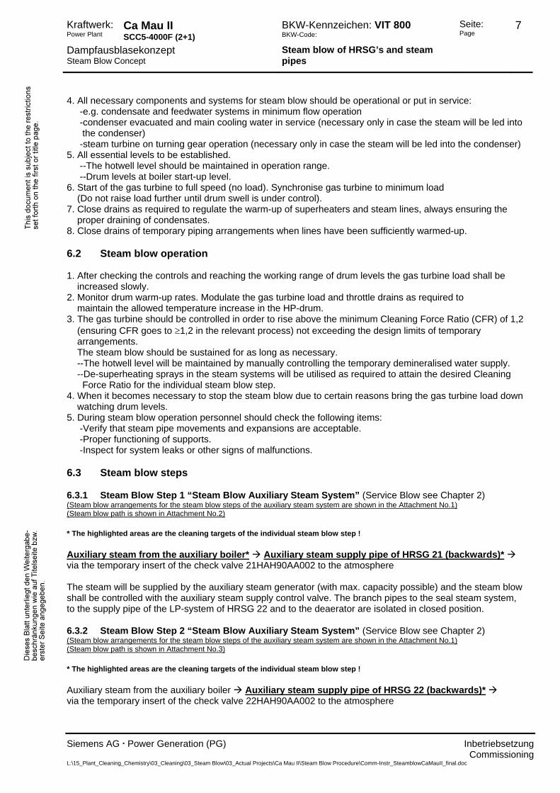
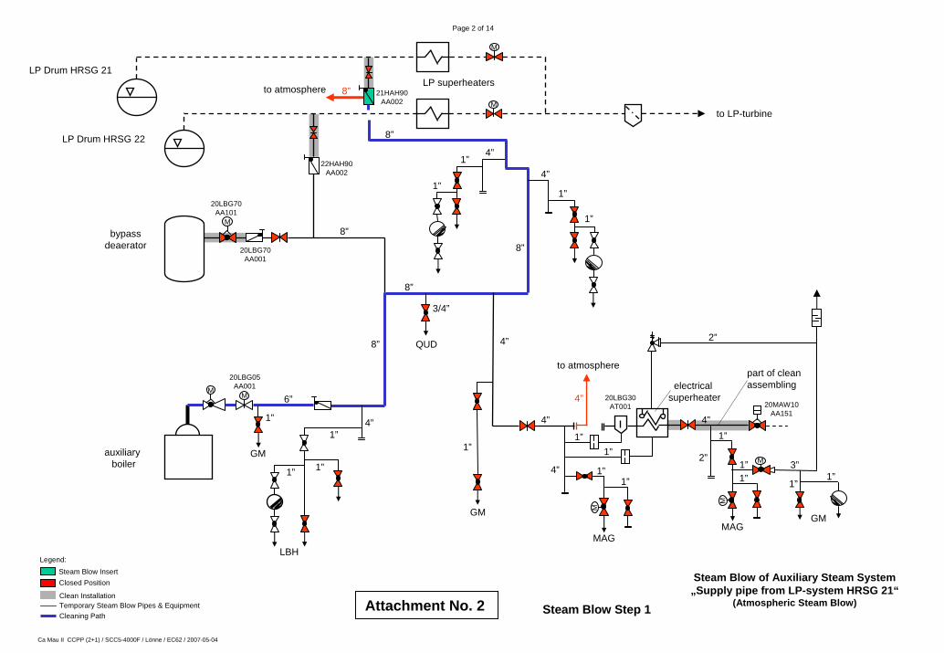
4. All necessary components and systems for steam blow should be operational or put in service: -e.g. condensate and feedwater systems in minimum flow operation -condenser evacuated and main cooling water in service (necessary only in case the steam will be led into the condenser) -steam turbine on turning gear operation (necessary only in case the steam will be led into the condenser) 5. All essential levels to be established. --The hotwell level should be maintained in operation range. --Drum levels at boiler start-up level. 6. Start of the gas turbine to full speed (no load). Synchronise gas turbine to minimum load (Do not raise load further until drum swell is under control). 7. Close drains as required to regulate the warm-up of superheaters and steam lines, always ensuring the proper draining of condensates. 8. Close drains of temporary piping arrangements when lines have been sufficiently warmed-up. 6.2 Steam blow operation 1. After checking the controls and reaching the working range of drum levels the gas turbine load shall be increased slowly. 2. Monitor drum warm-up rates. Modulate the gas turbine load and throttle drains as required to maintain the allowed temperature increase in the HP-drum. 3. The gas turbine should be controlled in order to rise above the minimum Cleaning Force Ratio (CFR) of 1,2 (ensuring CFR goes to ≥1,2 in the relevant process) not exceeding the design limits of temporary arrangements. The steam blow should be sustained for as long as necessary. --The hotwell level will be maintained by manually controlling the temporary demineralised water supply. --De-superheating sprays in the steam systems will be utilised as required to attain the desired Cleaning Force Ratio for the individual steam blow step. 4. When it becomes necessary to stop the steam blow due to certain reasons bring the gas turbine load down watching drum levels. 5. During steam blow operation personnel should check the following items: -Verify that steam pipe movements and expansions are acceptable. -Proper functioning of supports. -Inspect for system leaks or other signs of malfunctions. 6.3 Steam blow steps 6.3.1 Steam Blow Step 1 “Steam Blow Auxiliary Steam System” (Service Blow see Chapter 2) (Steam blow arrangements for the steam blow steps of the auxiliary steam system are shown in the Attachment No.1) (Steam blow path is shown in Attachment No.2) * The highlighted areas are the cleaning targets of the individual steam blow step ! Auxiliary steam from the auxiliary boiler* Auxiliary steam supply pipe of HRSG 21 (backwards)* via the temporary insert of the check valve 21HAH90AA002 to the atmosphere The steam will be supplied by the auxiliary steam generator (with max. capacity possible) and the steam blow shall be controlled with the auxiliary steam supply control valve. The branch pipes to the seal steam system, to the supply pipe of the LP-system of HRSG 22 and to the deaerator are isolated in closed position. 6.3.2 Steam Blow Step 2 “Steam Blow Auxiliary Steam System” (Service Blow see Chapter 2) (Steam blow arrangements for the steam blow steps of the auxiliary steam system are shown in the Attachment No.1) (Steam blow path is shown in Attachment No.3) * The highlighted areas are the cleaning targets of the individual steam blow step ! Auxiliary steam from the auxiliary boiler Auxiliary steam supply pipe of HRSG 22 (backwards)* via the temporary insert of the check valve 22HAH90AA002 to the atmosphere
Commissioning L:\15_Plant_Cleaning_Chemistry\03_Cleaning\03_Steam Blow\03_Actual Projects\Ca Mau II\Steam Blow Procedure\Comm-Instr_SteamblowCaMauII_final.doc

Kraftwerk: Power Plant
Ca Mau II SCC5-4000F (2+1)
BKW-Kennzeichen: VIT 800 BKW-Code:
Seite: Page
8
Dampfausblasekonzept Steam Blow Concept
Steam blow of HRSG’s and steam pipes
Siemens AG . Power Generation (PG) Inbetriebsetzung
The steam will be supplied by the auxiliary steam generator (with max. capacity possible) and the steam blow shall be controlled with the auxiliary steam supply control valve. The branch pipes to the seal steam system,
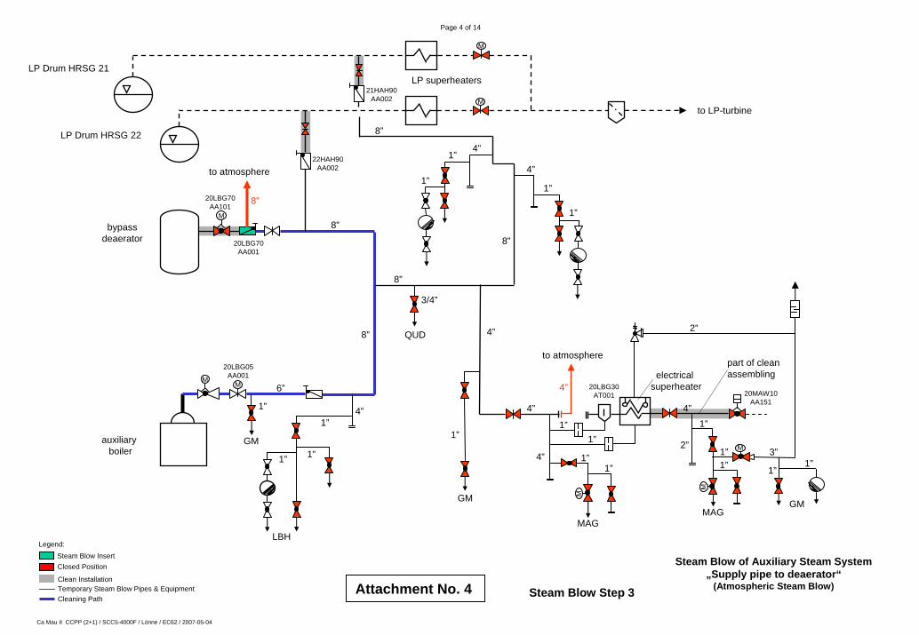
to the supply pipe of the LP-system of HRSG 21 and to the deaerator are isolated in closed position. 6.3.3 Steam Blow Step 3 “Steam Blow Auxiliary Steam System” (Service Blow see Chapter 2) (Steam blow arrangements for the steam blow steps of the auxiliary steam system are shown in the Attachment No.1) (Steam blow path is shown in Attachment No.4) * The highlighted areas are the cleaning targets of the individual steam blow step ! Auxiliary steam from the auxiliary boiler Auxiliary steam supply pipe to bypass deaerator* via the temporary insert of the check valve 20LBG70AA001 to the atmosphere The steam will be supplied by the auxiliary steam generator (with max. capacity possible) and the steam blow shall be controlled with the auxiliary steam supply control valve. The branch pipe to the seal steam system and the supply pipes of the LP-systems of HRSG’s are isolated in closed position. 6.3.4 Steam Blow Step 4 “Steam Blow Auxiliary Steam System” (Service Blow see Chapter 2) (Steam blow arrangements for the steam blow steps of the auxiliary steam system are shown in the Attachment No.1) (Steam blow path is shown in Attachment No.5) * The highlighted areas are the cleaning targets of the individual steam blow step ! Auxiliary steam from the auxiliary boiler Auxiliary steam pipe upstream the drop separator 20LBG30AT001* via the temporary pipe to the atmosphere The steam will be supplied by the auxiliary steam generator (with max. capacity possible) and the steam blow shall be controlled with the auxiliary steam supply control valve. The supply pipes from the LP-systems of HRSG’s and the pipe to the deaerator are isolated in closed position. 6.3.5 Steam Blow Step 5 “Atmospheric Steam Blow HP- System of HRSG 21” (Target Blow) (Steam blow arrangements for the steam blow steps of HRSG 21/ 22 and associated steam pipes are shown in the Attachment No.6 (Steam blow path is shown in the Attachment No.7) * The highlighted areas are the cleaning targets of the individual steam blow step ! HP-Superheaters 1-4 * (HRSG 21) HP-Steam Pipe * (HRSG 21) HP-Turbine Shut Off Valves Steam Blow Provision 1 Steam Blow Provision 2 via the silencer to the atmosphere and IP-Superheater (HRSG 21) Cold Reheat Pipe (HRSG 21) Reheater 1+2 (HRSG 21) Hot Reheat Pipe (HRSG 21) IP-Turbine Shut Off Valves Steam Blow Provision 2 via the silencer to the atmosphere and LP-Superheater (HRSG 21) LP-Steam Pipe (HRSG 21) Steam Blow Provision 3 via the silencer to the atmosphere Prior to the performance of this steam blow step the temporary changes (temporary protections) in the DCS-logic (valid for steam blow steps No.5) must be implemented (refer also to Chapter 4.1) ! For this steam blow step the HRSG’s and steam system piping will be aligned according to Attachment No.7. The HP-, IP- and LP- bypass stations (HRSG 21 + 22), the HP- steam gate valves (HRSG 22), the IP-steam gate valve (HRSG 22), the LP-steam gate valve (HRSG 22), the cold reheat inlet control dampers (HRSG 21 + 22) and the hot reheat gate valve (HRSG 22) are closed. The HP- , IP-, LP- and the hot reheat steam gate valves (HRSG 21) are completely open. The HP-steam pressure shall be controlled by means of the gas turbine load. The gas turbine load will be increased very slowly up to approximately 50 MW not exceeding the design limits of the temporary piping arrangement. Steam blow conditions (refer to the Attachment No.15): (Parameters are rough values and can be adapted one site) The gas turbine (GT 21) is in operation with approx. 50 MW load and the exhaust gas temperature is approx. 475°C.
Commissioning L:\15_Plant_Cleaning_Chemistry\03_Cleaning\03_Steam Blow\03_Actual Projects\Ca Mau II\Steam Blow Procedure\Comm-Instr_SteamblowCaMauII_final.doc

Kraftwerk: Power Plant
Ca Mau II SCC5-4000F (2+1)
BKW-Kennzeichen: VIT 800 BKW-Code:
Seite: Page
9
Dampfausblasekonzept Steam Blow Concept
Steam blow of HRSG’s and steam pipes
Siemens AG . Power Generation (PG) Inbetriebsetzung
The following steam blowing conditions are suggested: HP-Superheater Outlet Pb= 24.5 barabs, tb= 473 ºC mb= 1 x 41.2 kg/sec νb= 0.13751 m3/kg (temperature to be controlled to 400°C upstream of temporary piping by water injection!) Cold Reheat Intlet Pb = 1.8 barabs, tb= 387 ºC mb= 0 kg/sec νb= 1,651 m3/kg Hot Reheat Inlet Pb = 1.6 barabs, tb= 473 ºC mb= 1 x 8.5 kg/sec νb= 2.123 m3/kg Hot Reheat after water injection Pb = 1.6 barabs, tb= 400 ºC mb= 1 x 8.5 kg/sec νb= 1.914 m3/kg (temperature to be controlled by water injection !) IP-Superheater Outlet Pb = 1.8 barabs, tb= 240 ºC mb= 1 x 8.5 kg/sec νb= 1.307 m3/kg LP-Superheater Outlet Pb = 1.6 barabs, tb= 161 ºC mb= 1 x 3.3 kg/sec νb= 1.237 m3/kg Cleaning Force Ratios = CFR of > 1.2 in the relevant sections to be cleaned could be achieved. As a result the following steam blow velocities could be reached: HP-steam system: wb = approx. 112 m/sec in the 10” steam pipe With the completion of this steam blow step No.5 the HP-steam gate valves (HRSG 21) will be electrically isolated in “closed” position and mechanically locked. The cold reheat inlet control dampers (HRSG 21 + 22) remain in “closed” position. Afterwards the Unit will be configured for the next steam blow step. 6.3.6 Steam Blow Step 6 “Atmospheric Steam Blow HP- System of HRSG 22” (Target Blow) (Steam blow arrangements for the steam blow steps of HRSG 21/ 22 and associated steam pipes are shown in the Attachment No.6 (Steam blow path is shown in the Attachment No.8) * The highlighted areas are the cleaning targets of the individual steam blow step ! HP-Superheaters 1-4 * (HRSG 22) HP-Steam Pipe * (HRSG 22) HP-Turbine Shut Off Valves Steam Blow Provision 1 Steam Blow Provision 2 via the silencer to the atmosphere and IP-Superheater (HRSG 22) Cold Reheat Pipe (HRSG 22) Reheater 1+2 (HRSG 22) Hot Reheat Pipe (HRSG 22) IP-Turbine Shut Off Valves Steam Blow Provision 2 via the silencer to the atmosphere and LP-Superheater (HRSG 22) LP-Steam Pipe (HRSG 22) Steam Blow Provision 3 via the silencer to the atmosphere Prior to the performance of this steam blow step the temporary changes (temporary protections) in the DCS-logic (valid for steam blow steps No.6) must be implemented (refer also to Chapter 4.1) ! For this steam blow step the HRSG’s and steam system piping will be aligned according to Attachment No.8. The HP-, IP- and LP- bypass stations (HRSG 21 + 22), the HP- steam gate valves (HRSG 21), the IP-steam gate valve (HRSG 21), the LP-steam gate valve (HRSG 21), the cold reheat inlet control dampers (HRSG 21 + 22) and the hot reheat gate valve (HRSG 21) are closed. The HP- , IP-, LP- and the hot reheat steam gate valves (HRSG 22) are completely open. The HP-steam pressure shall be controlled by means of the gas turbine load. The gas turbine load will be increased very slowly up to approximately 50 MW not exceeding the design limits of the temporary piping arrangement. Steam blow conditions (refer to the Attachment No.15): (Parameters are rough values and can be adapted one site)
Commissioning L:\15_Plant_Cleaning_Chemistry\03_Cleaning\03_Steam Blow\03_Actual Projects\Ca Mau II\Steam Blow Procedure\Comm-Instr_SteamblowCaMauII_final.doc

Kraftwerk: Power Plant
Ca Mau II SCC5-4000F (2+1)
BKW-Kennzeichen: VIT 800 BKW-Code:
Seite: Page
10
Dampfausblasekonzept Steam Blow Concept
Steam blow of HRSG’s and steam pipes
Siemens AG . Power Generation (PG) Inbetriebsetzung
The gas turbine (GT 22) is in operation with approx. 50 MW load and the exhaust gas temperature is
approx. 475°C. The following steam blowing conditions are suggested: HP-Superheater Outlet Pb= 24.5 barabs, tb= 473 ºC mb= 1 x 41.2 kg/sec νb= 0.13751 m3/kg (temperature to be controlled to 400°C upstream of temporary piping by water injection!) Cold Reheat Intlet Pb = 1.8 barabs, tb= 387 ºC mb= 0 kg/sec νb= 1,651 m3/kg Hot Reheat Inlet Pb = 1.6 barabs, tb= 473 ºC mb= 1 x 8.5 kg/sec νb= 2.123 m3/kg Hot Reheat after water injection Pb = 1.6 barabs, tb= 400 ºC mb= 1 x 8.5 kg/sec νb= 1.914 m3/kg (temperature to be controlled by water injection !) IP-Superheater Outlet Pb = 1.8 barabs, tb= 240 ºC mb= 1 x 8.5 kg/sec νb= 1.307 m3/kg LP-Superheater Outlet Pb = 1.6 barabs, tb= 161 ºC mb= 1 x 3.3 kg/sec νb= 1.237 m3/kg Cleaning Force Ratios = CFR of > 1.2 in the relevant sections to be cleaned could be achieved. As a result the following steam blow velocities could be reached: HP-steam system: wb = approx. 112 m/sec in the 10” steam pipe With the completion of this steam blow step No.6 the HP-steam gate valves (HRSG 22) will be electrically isolated in “closed” position and mechanically locked. The cold reheat inlet control dampers (HRSG 21 + 22) remain in “closed” position. The temporary pipe spool piece in the Steam Blow Provision No.1 shall be connected to the temporary inlet pipe of the CRH check valve insert and the blind disc from the temporary CRH inlet pipe will be moved to the connection of the temporary spool piece inlet at the Steam Blow Provision No.2. Afterwards the Unit will be configured for the next steam blow step. 6.3.7 Steam Blow Step 7 “Atmospheric Steam Blow HP-Bypass & IP-System of HRSG 21” (Target Blow) (Steam blow arrangements for the steam blow steps of HRSG 21/ 22 and associated steam pipes are shown in the Attachment No.6 (Steam blow path is shown in the Attachment No.9) * The highlighted areas are the cleaning targets of the individual steam blow step ! HP-Superheater 1-4 (HRSG 21) HP-Steam Pipe (HRSG 21) HP-Bypass * (HRSG 21) Cold Reheat Pipe (HRSG 21partly) Reheater 1+2 (HRSG 21) Hot Reheat Pipe (HRSG 21) IP-Turbine Shut Off Valves Steam Blow Provision 2 via the silencer to the atmosphere and from IP-Superheater * (HRSG 21) Cold Reheat Pipe (HRSG 21partly) Reheater 1+2 (HRSG 21) Hot Reheat Pipe (HRSG 21) IP-Turbine Shut Off Valves Steam Blow Provision 2 via the silencer to the atmosphere Prior to the performance of this steam blow step the temporary changes for the HP-pressure, HP-temperature and HP-bypass setpoint (temporary protections, refer also to Chapter 4.1) in the DCS-logic must be re-adjusted to the original settings (valid for steam blow steps No.7) !! For this steam blow step the HRSG’s and steam system piping will be aligned according to Attachment No.9. The HP-steam gate valves of the HRSG 21 + 22, the HP-bypass station of HRSG 22, the IP- and LP- bypass stations (HRSG 21 + 22), the HP- , IP- and LP- steam gate valves (HRSG 22) and the cold reheat inlet dampers (HRSG 21 + 22) are closed. The IP-, HRH- and LP-steam gate valves of HRSG 21 are open. The HP-steam pressure shall be controlled by the HP-bypass station of HRSG 21. The pressure in the cold reheat pipe will be adjusted by means of the gas turbine load.
Commissioning L:\15_Plant_Cleaning_Chemistry\03_Cleaning\03_Steam Blow\03_Actual Projects\Ca Mau II\Steam Blow Procedure\Comm-Instr_SteamblowCaMauII_final.doc

Kraftwerk: Power Plant
Ca Mau II SCC5-4000F (2+1)
BKW-Kennzeichen: VIT 800 BKW-Code:
Seite: Page
11
Dampfausblasekonzept Steam Blow Concept
Steam blow of HRSG’s and steam pipes
Siemens AG . Power Generation (PG) Inbetriebsetzung
The gas turbine load will be increased very slowly up to approximately 50 MW not exceeding the design limits of the temporary piping arrangement.
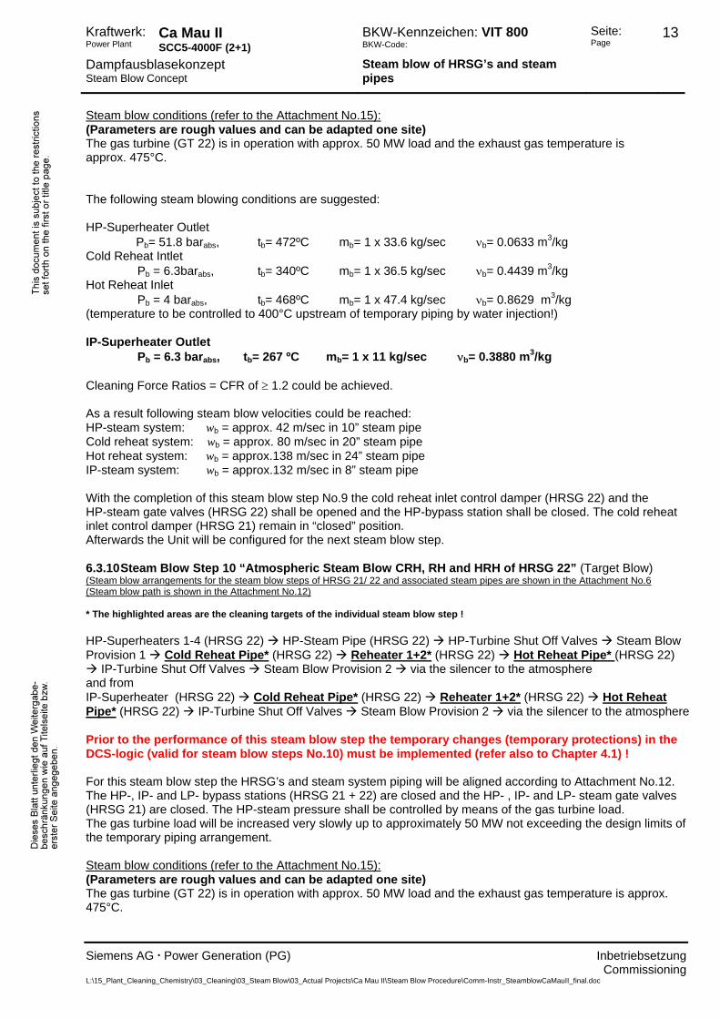
Steam blow conditions (refer to the Attachment No.15): (Parameters are rough values and can be adapted one site) The gas turbine (GT 21) is in operation with approx. 50 MW load and the exhaust gas temperature is approx. 475°C. The following steam blowing conditions are suggested: HP-Superheater Outlet Pb= 51.8 barabs, tb= 472ºC mb= 1 x 33.6 kg/sec νb= 0.0633 m3/kg Cold Reheat Intlet Pb = 6.3barabs, tb= 340ºC mb= 1 x 36.5 kg/sec νb= 0.4439 m3/kg Hot Reheat Inlet Pb = 4 barabs, tb= 468ºC mb= 1 x 47.4 kg/sec νb= 0.8629 m3/kg (temperature to be controlled to 400°C upstream of temporary piping by water injection!) IP-Superheater Outlet Pb = 6.3 barabs, tb= 267 ºC mb= 1 x 11 kg/sec νb= 0.3880 m3/kg Cleaning Force Ratios = CFR of ≥ 1.2 could be achieved. As a result following steam blow velocities could be reached: HP-steam system: wb = approx. 42 m/sec in 10” steam pipe Cold reheat system: wb = approx. 80 m/sec in 20” steam pipe Hot reheat system: wb = approx.138 m/sec in 24” steam pipe IP-steam system: wb = approx.132 m/sec in 8” steam pipe With the completion of this steam blow step No.7 the cold reheat inlet control damper and the HP-steam gate valves (HRSG 21) shall be opened and the HP-bypass station shall be closed. The cold reheat inlet control damper (HRSG 22) remain in “closed” position. Afterwards the Unit will be configured for the next steam blow step. 6.3.8 Steam Blow Step 8 “Atmospheric Steam Blow CRH, RH and HRH of HRSG 21” (Target Blow) (Steam blow arrangements for the steam blow steps of HRSG 21/ 22 and associated steam pipes are shown in the Attachment No.6 (Steam blow path is shown in the Attachment No.10) * The highlighted areas are the cleaning targets of the individual steam blow step ! HP-Superheaters 1-4 (HRSG 21) HP-Steam Pipe (HRSG 21) HP-Turbine Shut Off Valves Steam Blow Provision 1 Cold Reheat Pipe* (HRSG 21) Reheater 1+2* (HRSG 21) Hot Reheat Pipe* (HRSG 21)
IP-Turbine Shut Off Valves Steam Blow Provision 2 via the silencer to the atmosphere and from IP-Superheater (HRSG 21) Cold Reheat Pipe* (HRSG 21) Reheater 1+2* (HRSG 21) Hot Reheat Pipe* (HRSG 21) IP-Turbine Shut Off Valves Steam Blow Provision 2 via the silencer to the atmosphere Prior to the performance of this steam blow step the temporary changes (temporary protections) in the DCS-logic (valid for steam blow steps No.8) must be implemented (refer also to Chapter 4.1) ! For this steam blow step the HRSG’s and steam system piping will be aligned according to Attachment No.10. The HP-, IP- and LP- bypass stations (HRSG 21 + 22) are closed and the HP- , IP- and LP- steam gate valves (HRSG 22) are closed. The HP-steam pressure shall be controlled by means of the gas turbine load. The gas turbine load will be increased very slowly up to approximately 50 MW not exceeding the design limits of the temporary piping arrangement. Steam blow conditions (refer to the Attachment No.15): (Parameters are rough values and can be adapted one site)
Commissioning L:\15_Plant_Cleaning_Chemistry\03_Cleaning\03_Steam Blow\03_Actual Projects\Ca Mau II\Steam Blow Procedure\Comm-Instr_SteamblowCaMauII_final.doc

Kraftwerk: Power Plant
Ca Mau II SCC5-4000F (2+1)
BKW-Kennzeichen: VIT 800 BKW-Code:
Seite: Page
12
Dampfausblasekonzept Steam Blow Concept
Steam blow of HRSG’s and steam pipes
Siemens AG . Power Generation (PG) Inbetriebsetzung
The gas turbine (GT 21) is in operation with approx. 50 MW load and the exhaust gas temperature is
approx. 475°C. The following steam blowing conditions are suggested: HP-Superheater Outlet Pb= 24.0 barabs, tb= 472ºC mb= 1 x 39.3 kg/sec νb= 0.1423 m3/kg (temperature to be controlled to 400°C upstream of temporary piping by water injection !) Cold Reheat Intlet Pb = 7.3 barabs, tb= 400ºC mb= 1 x 41.2 kg/sec νb= 0.4215 m3/kg Hot Reheat Inlet Pb = 4.0 barabs, tb= 469ºC mb= 1 x 48.2 kg/sec νb= 0.8532 m3/kg (temperature to be controlled to 400°C upstream of temporary piping by water injection!) IP-Superheater Outlet Pb = 6.5 barabs, tb= 241ºC mb= 1 x 7.0 kg/sec νb= 0.3560 m3/kg Cleaning Force Ratios = CFR of ≥ 1.2 could be achieved. As a result following steam blow velocities could be reached: HP-steam system: wb = approx.109 m/sec in 10” steam pipe Cold reheat system: wb = approx. 86 m/sec in 20” steam pipe Hot reheat system: wb = approx.141 m/sec in 24” steam pipe IP-steam system: wb = approx. 77 m/sec in 8” steam pipe With the completion of this steam blow step No.8 the cold reheat inlet control dampers (HRSG 21 + 22) and the HP-steam gate valves (HRSG 21 + 22) shall be closed and the HP-bypass station (HRSG 22) shall be closed. Afterwards the Unit will be configured for the next steam blow step. 6.3.9 Steam Blow Step 9 “Atmospheric Steam Blow HP-Bypass & IP-System of HRSG 22” (Target Blow) (Steam blow arrangements for the steam blow steps of HRSG 21/ 22 and associated steam pipes are shown in the Attachment No.6 (Steam blow path is shown in the Attachment No.11) * The highlighted areas are the cleaning targets of the individual steam blow step ! HP-Superheater 1-4 (HRSG 22) HP-Steam Pipe (HRSG 22) HP-Bypass * (HRSG 22) Cold Reheat Pipe (HRSG 22partly) Reheater 1+2 (HRSG 22) Hot Reheat Pipe (HRSG 22) IP-Turbine Shut Off Valves Steam Blow Provision 2 via the silencer to the atmosphere and from IP-Superheater * (HRSG 22) Cold Reheat Pipe (HRSG 22partly) Reheater 1+2 (HRSG 22) Hot Reheat Pipe (HRSG 22) IP-Turbine Shut Off Valves Steam Blow Provision 2 via the silencer to the atmosphere Prior to the performance of this steam blow step the temporary changes for the HP-pressure, HP-temperature and HP-bypass setpoint (temporary protections, refer also to Chapter 4.1) in the DCS-logic must be re-adjusted to the original settings (valid for steam blow steps No.9) !! For this steam blow step the HRSG’s and steam system piping will be aligned according to Attachment No.11. The HP-steam gate valves of the HRSG 21 + 22, the HP-bypass station of HRSG 21, the IP- and LP- bypass stations (HRSG 21 + 22), the HP- , IP- and LP- steam gate valves (HRSG 21) and the cold reheat inlet dampers (HRSG 21 + 22) are closed. The IP-, HRH- and LP-steam gate valves of HRSG 22 are open. The HP-steam pressure shall be controlled by the HP-bypass station of HRSG 22. The pressure in the cold reheat pipe will be adjusted by means of the gas turbine load. The gas turbine load will be increased very slowly up to approximately 50 MW not exceeding the design limits of the temporary piping arrangement.
Commissioning L:\15_Plant_Cleaning_Chemistry\03_Cleaning\03_Steam Blow\03_Actual Projects\Ca Mau II\Steam Blow Procedure\Comm-Instr_SteamblowCaMauII_final.doc
Kraftwerk: Power Plant
Ca Mau II SCC5-4000F (2+1)
BKW-Kennzeichen: VIT 800 BKW-Code:
Seite: Page
13
Dampfausblasekonzept Steam Blow Concept
Steam blow of HRSG’s and steam pipes
Siemens AG . Power Generation (PG) Inbetriebsetzung
Steam blow conditions (refer to the Attachment No.15):
(Parameters are rough values and can be adapted one site) The gas turbine (GT 22) is in operation with approx. 50 MW load and the exhaust gas temperature is approx. 475°C. The following steam blowing conditions are suggested: HP-Superheater Outlet Pb= 51.8 barabs, tb= 472ºC mb= 1 x 33.6 kg/sec νb= 0.0633 m3/kg Cold Reheat Intlet Pb = 6.3barabs, tb= 340ºC mb= 1 x 36.5 kg/sec νb= 0.4439 m3/kg Hot Reheat Inlet Pb = 4 barabs, tb= 468ºC mb= 1 x 47.4 kg/sec νb= 0.8629 m3/kg (temperature to be controlled to 400°C upstream of temporary piping by water injection!) IP-Superheater Outlet Pb = 6.3 barabs, tb= 267 ºC mb= 1 x 11 kg/sec νb= 0.3880 m3/kg Cleaning Force Ratios = CFR of ≥ 1.2 could be achieved. As a result following steam blow velocities could be reached: HP-steam system: wb = approx. 42 m/sec in 10” steam pipe Cold reheat system: wb = approx. 80 m/sec in 20” steam pipe Hot reheat system: wb = approx.138 m/sec in 24” steam pipe IP-steam system: wb = approx.132 m/sec in 8” steam pipe With the completion of this steam blow step No.9 the cold reheat inlet control damper (HRSG 22) and the HP-steam gate valves (HRSG 22) shall be opened and the HP-bypass station shall be closed. The cold reheat inlet control damper (HRSG 21) remain in “closed” position. Afterwards the Unit will be configured for the next steam blow step. 6.3.10 Steam Blow Step 10 “Atmospheric Steam Blow CRH, RH and HRH of HRSG 22” (Target Blow) (Steam blow arrangements for the steam blow steps of HRSG 21/ 22 and associated steam pipes are shown in the Attachment No.6 (Steam blow path is shown in the Attachment No.12) * The highlighted areas are the cleaning targets of the individual steam blow step ! HP-Superheaters 1-4 (HRSG 22) HP-Steam Pipe (HRSG 22) HP-Turbine Shut Off Valves Steam Blow Provision 1 Cold Reheat Pipe* (HRSG 22) Reheater 1+2* (HRSG 22) Hot Reheat Pipe* (HRSG 22)
IP-Turbine Shut Off Valves Steam Blow Provision 2 via the silencer to the atmosphere and from IP-Superheater (HRSG 22) Cold Reheat Pipe* (HRSG 22) Reheater 1+2* (HRSG 22) Hot Reheat Pipe* (HRSG 22) IP-Turbine Shut Off Valves Steam Blow Provision 2 via the silencer to the atmosphere Prior to the performance of this steam blow step the temporary changes (temporary protections) in the DCS-logic (valid for steam blow steps No.10) must be implemented (refer also to Chapter 4.1) ! For this steam blow step the HRSG’s and steam system piping will be aligned according to Attachment No.12. The HP-, IP- and LP- bypass stations (HRSG 21 + 22) are closed and the HP- , IP- and LP- steam gate valves (HRSG 21) are closed. The HP-steam pressure shall be controlled by means of the gas turbine load. The gas turbine load will be increased very slowly up to approximately 50 MW not exceeding the design limits of the temporary piping arrangement. Steam blow conditions (refer to the Attachment No.15): (Parameters are rough values and can be adapted one site) The gas turbine (GT 22) is in operation with approx. 50 MW load and the exhaust gas temperature is approx. 475°C.
Commissioning L:\15_Plant_Cleaning_Chemistry\03_Cleaning\03_Steam Blow\03_Actual Projects\Ca Mau II\Steam Blow Procedure\Comm-Instr_SteamblowCaMauII_final.doc
Kraftwerk: Power Plant
Ca Mau II SCC5-4000F (2+1)
BKW-Kennzeichen: VIT 800 BKW-Code:
Seite: Page
14
Dampfausblasekonzept Steam Blow Concept
Steam blow of HRSG’s and steam pipes
Siemens AG . Power Generation (PG) Inbetriebsetzung
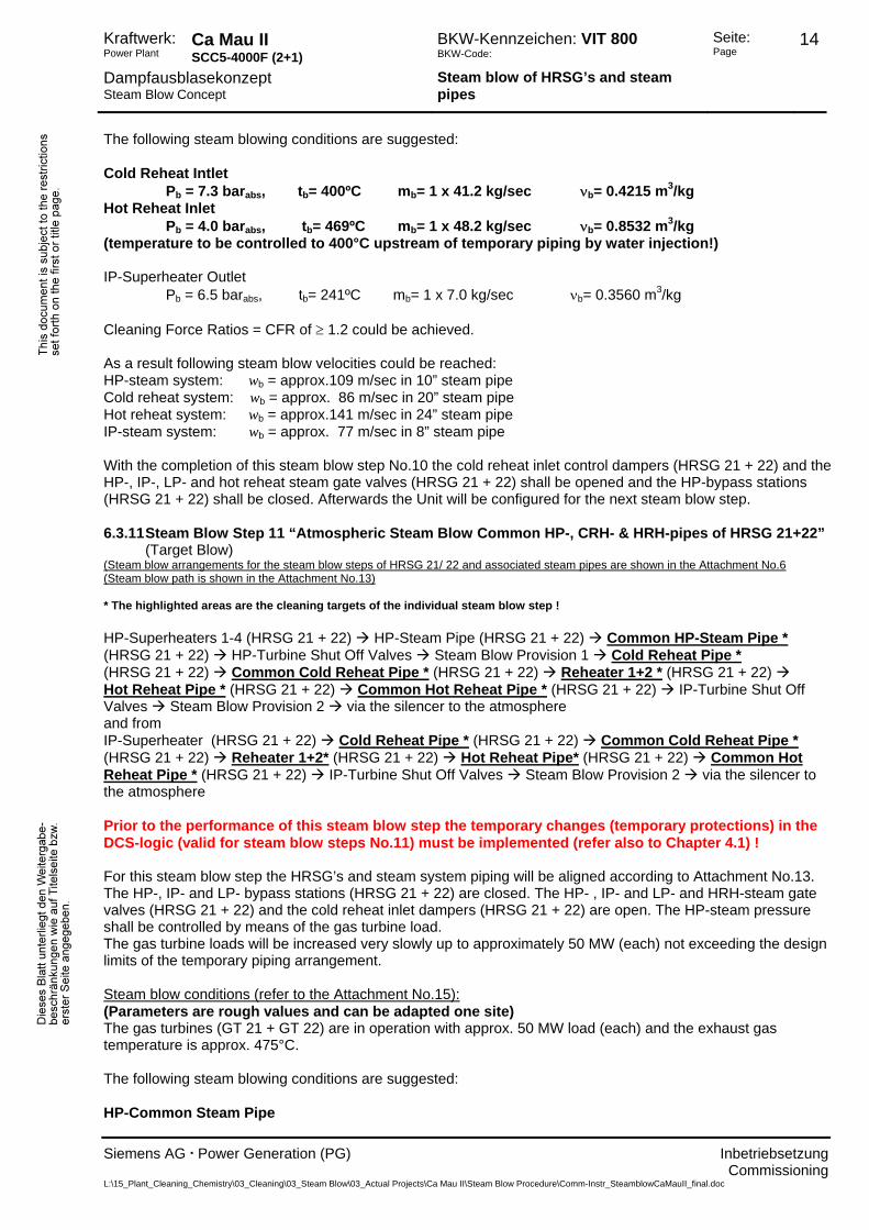
The following steam blowing conditions are suggested:
Cold Reheat Intlet Pb = 7.3 barabs, tb= 400ºC mb= 1 x 41.2 kg/sec νb= 0.4215 m3/kg Hot Reheat Inlet Pb = 4.0 barabs, tb= 469ºC mb= 1 x 48.2 kg/sec νb= 0.8532 m3/kg (temperature to be controlled to 400°C upstream of temporary piping by water injection!) IP-Superheater Outlet Pb = 6.5 barabs, tb= 241ºC mb= 1 x 7.0 kg/sec νb= 0.3560 m3/kg Cleaning Force Ratios = CFR of ≥ 1.2 could be achieved. As a result following steam blow velocities could be reached: HP-steam system: wb = approx.109 m/sec in 10” steam pipe Cold reheat system: wb = approx. 86 m/sec in 20” steam pipe Hot reheat system: wb = approx.141 m/sec in 24” steam pipe IP-steam system: wb = approx. 77 m/sec in 8” steam pipe With the completion of this steam blow step No.10 the cold reheat inlet control dampers (HRSG 21 + 22) and the HP-, IP-, LP- and hot reheat steam gate valves (HRSG 21 + 22) shall be opened and the HP-bypass stations (HRSG 21 + 22) shall be closed. Afterwards the Unit will be configured for the next steam blow step. 6.3.11 Steam Blow Step 11 “Atmospheric Steam Blow Common HP-, CRH- & HRH-pipes of HRSG 21+22”
(Target Blow) (Steam blow arrangements for the steam blow steps of HRSG 21/ 22 and associated steam pipes are shown in the Attachment No.6 (Steam blow path is shown in the Attachment No.13) * The highlighted areas are the cleaning targets of the individual steam blow step ! HP-Superheaters 1-4 (HRSG 21 + 22) HP-Steam Pipe (HRSG 21 + 22) Common HP-Steam Pipe * (HRSG 21 + 22) HP-Turbine Shut Off Valves Steam Blow Provision 1 Cold Reheat Pipe * (HRSG 21 + 22) Common Cold Reheat Pipe * (HRSG 21 + 22) Reheater 1+2 * (HRSG 21 + 22) Hot Reheat Pipe * (HRSG 21 + 22) Common Hot Reheat Pipe * (HRSG 21 + 22) IP-Turbine Shut Off Valves Steam Blow Provision 2 via the silencer to the atmosphere and from IP-Superheater (HRSG 21 + 22) Cold Reheat Pipe * (HRSG 21 + 22) Common Cold Reheat Pipe * (HRSG 21 + 22) Reheater 1+2* (HRSG 21 + 22) Hot Reheat Pipe* (HRSG 21 + 22) Common Hot Reheat Pipe * (HRSG 21 + 22) IP-Turbine Shut Off Valves Steam Blow Provision 2 via the silencer to the atmosphere Prior to the performance of this steam blow step the temporary changes (temporary protections) in the DCS-logic (valid for steam blow steps No.11) must be implemented (refer also to Chapter 4.1) ! For this steam blow step the HRSG’s and steam system piping will be aligned according to Attachment No.13. The HP-, IP- and LP- bypass stations (HRSG 21 + 22) are closed. The HP- , IP- and LP- and HRH-steam gate valves (HRSG 21 + 22) and the cold reheat inlet dampers (HRSG 21 + 22) are open. The HP-steam pressure shall be controlled by means of the gas turbine load. The gas turbine loads will be increased very slowly up to approximately 50 MW (each) not exceeding the design limits of the temporary piping arrangement. Steam blow conditions (refer to the Attachment No.15): (Parameters are rough values and can be adapted one site) The gas turbines (GT 21 + GT 22) are in operation with approx. 50 MW load (each) and the exhaust gas temperature is approx. 475°C. The following steam blowing conditions are suggested: HP-Common Steam Pipe
Commissioning L:\15_Plant_Cleaning_Chemistry\03_Cleaning\03_Steam Blow\03_Actual Projects\Ca Mau II\Steam Blow Procedure\Comm-Instr_SteamblowCaMauII_final.doc

Kraftwerk: Power Plant
Ca Mau II SCC5-4000F (2+1)
BKW-Kennzeichen: VIT 800 BKW-Code:
Seite: Page
15
Dampfausblasekonzept Steam Blow Concept
Steam blow of HRSG’s and steam pipes
Siemens AG . Power Generation (PG) Inbetriebsetzung
Pb= 19 barabs, tb= 411ºC mb= 81.3 kg/sec νb= 0.16255 m3/kg
(temperature to be controlled to 400°C upstream of temporary piping by water injection!) Common Cold Reheat Pipe Pb = 7.9 barabs, tb= 400ºC mb= 81.3 kg/sec νb= 0.3892 m3/kg Common Hot Reheat Pipe Pb = 3.5 barabs, tb= 402ºC mb= 100.9 kg/sec νb= 0.8863 m3/kg (temperature to be controlled to 400°C upstream of temporary piping by water injection!) IP-Superheater Outlet Pb = 7 barabs, tb= 245ºC mb= 2 x 7.4 kg/sec νb= 0.3328 m3/kg Cleaning Force Ratios = CFR of ≥ 1.2 could be achieved. As a result following steam blow velocities could be reached: Common HP-steam pipe: wb = approx. 133 m/sec in 14” steam pipe Common Cold reheat pipe: wb = approx. 80 m/sec in 28” steam pipe Common Hot reheat pipe: wb = approx. 196 m/sec in 30” steam pipe With the completion of this steam blow step No.11 the HP-steam gate valves (HRSG 21 + 22), the cold reheat inlet control dampers (HRSG 21 + 22), the hot reheat steam gate valves (HRSG 21 + 22) and the LP-bypass station shall be closed. Afterwards the Unit will be configured for the next steam blow step. The HP- and IP-bypass stations (HRSG 21+ 22) will be operated during the blow step No.12 in controlled open manner. 6.3.12 Steam Blow Step 12 “Atmospheric Steam Blow LP-System of HRSG 21 + 22” (Target Blow) (Steam blow arrangements for the steam blow steps of HRSG 21/ 22 and associated steam pipes are shown in the Attachment No.6 (Steam blow path is shown in the Attachment No.14) * The highlighted areas are the cleaning targets of the individual steam blow step ! LP-Superheater * (HRSG 21 + 22) LP-Steam Pipes * (HRSG 21 + 22) LP-Turbine Steam Strainer * (strainer insert temporarily removed) Steam Blow Provision 3 via the silencer to the atmosphere Prior to the performance of this steam blow step the temporary changes for the HP-pressure, HP-temperature and HP-bypass setpoint (temporary protections, refer also to Chapter 4.1) in the DCS-logic must be re-adjusted to the original settings (valid for steam blow steps No.12) !! For this steam blow step the HRSG’s and steam system piping will be aligned according to Attachment No.14. The temporary piping provisions 1+2 are isolated and the HP- and IP- systems (HRSG 21 + 22) will be operated in normal bypass mode while the LP-superheaters and steam pipes will be blown out to the atmosphere. With the completion of this steam blow step the steam blow cleaning is finalised. Steam blow conditions (refer to the Attachment No.15): (Parameters are rough values and can be adapted one site) The gas turbines (GT 21 + GT 22) are in operation with approx. 40 MW load (each) and the exhaust gas temperature is approx. 451°C. The HP- and IP-systems are operated in normal bypass operation. The following steam blowing conditions are suggested: LP-Superheater Outlet Pb= 2.2 barabs, tb= 210 ºC mb= 2 x 7.9 kg/sec νb= 1.0029 m3/kg Common LP-Steam Pipe Pb= 1.8 barabs, tb= 209 ºC mb= 15.9 kg/sec νb= 1.2256 m3/kg A Cleaning Force Ratio = CFR of ≥ 1.2 could be achieved.
Commissioning L:\15_Plant_Cleaning_Chemistry\03_Cleaning\03_Steam Blow\03_Actual Projects\Ca Mau II\Steam Blow Procedure\Comm-Instr_SteamblowCaMauII_final.doc
Kraftwerk: Power Plant
Ca Mau II SCC5-4000F (2+1)
BKW-Kennzeichen: VIT 800 BKW-Code:
Seite: Page
16
Dampfausblasekonzept Steam Blow Concept
Steam blow of HRSG’s and steam pipes
Siemens AG . Power Generation (PG) Inbetriebsetzung
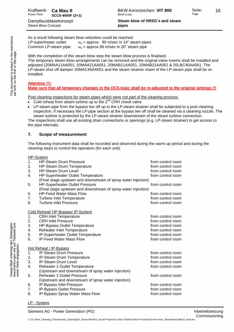
As a result following steam blow velocities could be reached:
LP-superheater outlet: wb = approx. 80 m/sec in 14” steam pipes Common LP-steam pipe: wb = approx.96 m/sec in 20” steam pipe With the completion of this steam blow step the steam blow process is finalised. The temporary steam blow arrangements can be removed and the original valve inserts shall be installed and adjusted (20MAA11AA051, 20MAA21AA051, 20MAB11AA051, 20MAB21AA051 & 20LBC40AA051. The LP-steam shut off damper 20MAC45AA051 and the steam strainer insert of the LP-steam pipe shall be re-installed. Attention !!!: Make sure that all temporary changes in the DCS-logic shall be re-adjusted to the original settings !!! Post cleaning inspections for steam pipes which were not part of the cleaning process: • Cold reheat from steam turbine up to the 2nd CRH check valve • LP-steam pipe from the bypass tee off up to the LP-steam strainer shall be subjected to a post cleaning
inspection. If necessary the LP-pipe section at the bypass tee off shall be cleaned via a cleaning nozzle. The steam turbine is protected by the LP-steam strainer downstream of the steam turbine connection.
The inspections shall use all existing drain connections or openings (e.g. LP-steam strainer) to get access to the pipe internals. 7. Scope of measurement The following instrument data shall be recorded and observed during the warm up period and during the cleaning steps to control the operation (for each unit). HP-System 1. HP-Steam Drum Pressure from control room 2. HP-Steam Drum Temperature from control room 3. HP-Steam Drum Level from control room 4. HP-Superheater Outlet Temperature from control room (Final stage upsteam and downstream of spray water injection) 5. HP-Superheater Outlet Pressure from control room (Final stage upsteam and downstream of spray water injection) 6. HP-Feed Water Mass Flow from control room 7. Turbine Inlet Temperature from control room 8. Turbine Inlet Pressure from control room Cold Reheat/ HP-Bypass/ IP-System 1. CRH Inlet Temperature from control room 2. CRH Inlet Pressure from control room 3. HP-Bypass Outlet Temperature from control room 4. Reheater Inlet Temperature from control room 5. IP-Superheater Outlet Temperature from control room 6. IP-Feed Water Mass Flow from control room Hot Reheat / IP-Bypass 1. IP-Steam Drum Pressure from control room 2. IP-Steam Drum Temperature from control room 3. IP-Steam Drum Level from control room 4. Reheater 2 Outlet Temperature from control room (Upstream and downstream of spray water injection) 5. Reheater 2 Outlet Pressure from control room (Upstream and downstream of spray water injection) 6. IP-Bypass Inlet Pressure from control room 7. IP-Bypass Outlet Pressure from control room 8. IP-Bypass Spray Water Mass Flow from control room LP - System
Commissioning L:\15_Plant_Cleaning_Chemistry\03_Cleaning\03_Steam Blow\03_Actual Projects\Ca Mau II\Steam Blow Procedure\Comm-Instr_SteamblowCaMauII_final.doc
Kraftwerk: Power Plant
Ca Mau II SCC5-4000F (2+1)
BKW-Kennzeichen: VIT 800 BKW-Code:
Seite: Page
17
Dampfausblasekonzept Steam Blow Concept
Steam blow of HRSG’s and steam pipes
Siemens AG . Power Generation (PG) Inbetriebsetzung
1. LP-Steam Drum Pressure from control room
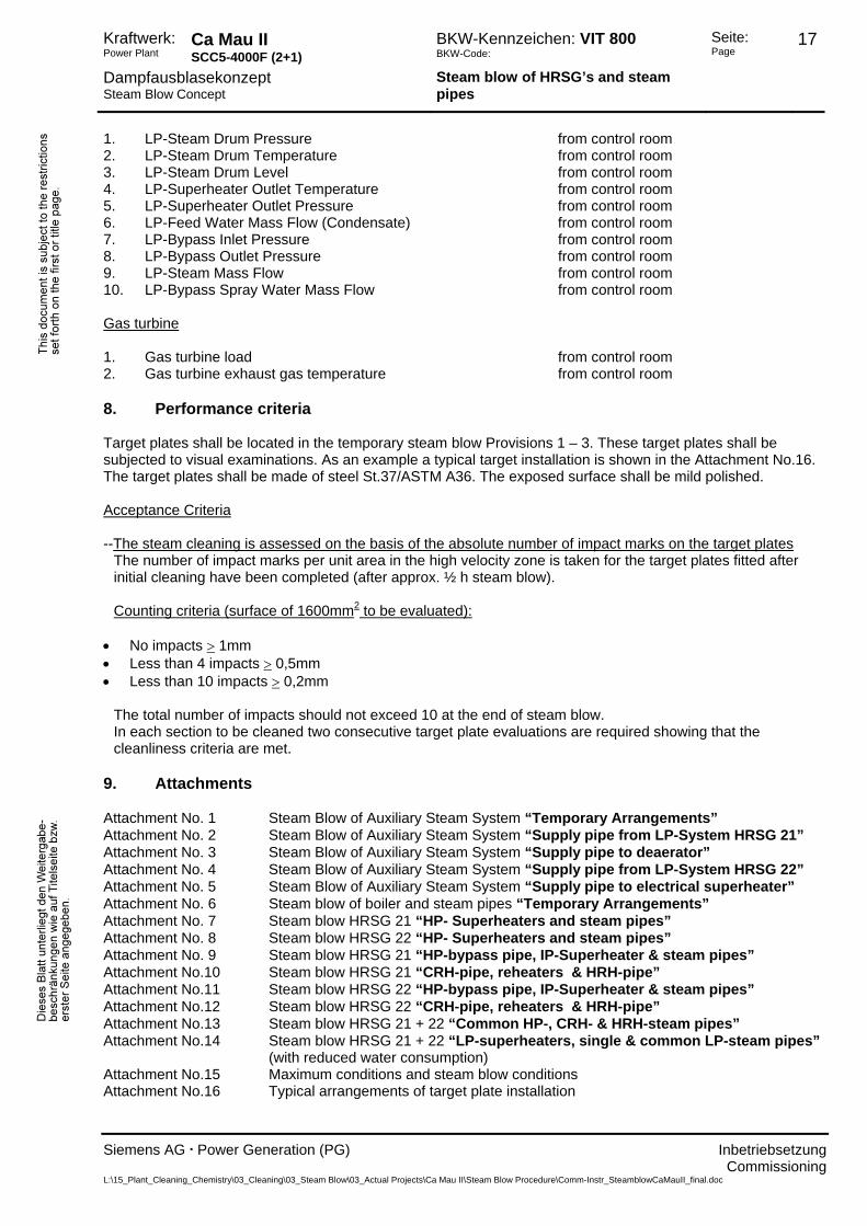
2. LP-Steam Drum Temperature from control room 3. LP-Steam Drum Level from control room 4. LP-Superheater Outlet Temperature from control room 5. LP-Superheater Outlet Pressure from control room 6. LP-Feed Water Mass Flow (Condensate) from control room 7. LP-Bypass Inlet Pressure from control room 8. LP-Bypass Outlet Pressure from control room 9. LP-Steam Mass Flow from control room 10. LP-Bypass Spray Water Mass Flow from control room Gas turbine 1. Gas turbine load from control room 2. Gas turbine exhaust gas temperature from control room 8. Performance criteria Target plates shall be located in the temporary steam blow Provisions 1 – 3. These target plates shall be subjected to visual examinations. As an example a typical target installation is shown in the Attachment No.16. The target plates shall be made of steel St.37/ASTM A36. The exposed surface shall be mild polished. Acceptance Criteria --The steam cleaning is assessed on the basis of the absolute number of impact marks on the target plates
The number of impact marks per unit area in the high velocity zone is taken for the target plates fitted after initial cleaning have been completed (after approx. ½ h steam blow). Counting criteria (surface of 1600mm2 to be evaluated):
• No impacts > 1mm • Less than 4 impacts > 0,5mm • Less than 10 impacts > 0,2mm
The total number of impacts should not exceed 10 at the end of steam blow. In each section to be cleaned two consecutive target plate evaluations are required showing that the cleanliness criteria are met.
9. Attachments Attachment No. 1 Steam Blow of Auxiliary Steam System “Temporary Arrangements” Attachment No. 2 Steam Blow of Auxiliary Steam System “Supply pipe from LP-System HRSG 21” Attachment No. 3 Steam Blow of Auxiliary Steam System “Supply pipe to deaerator” Attachment No. 4 Steam Blow of Auxiliary Steam System “Supply pipe from LP-System HRSG 22” Attachment No. 5 Steam Blow of Auxiliary Steam System “Supply pipe to electrical superheater” Attachment No. 6 Steam blow of boiler and steam pipes “Temporary Arrangements” Attachment No. 7 Steam blow HRSG 21 “HP- Superheaters and steam pipes” Attachment No. 8 Steam blow HRSG 22 “HP- Superheaters and steam pipes” Attachment No. 9 Steam blow HRSG 21 “HP-bypass pipe, IP-Superheater & steam pipes” Attachment No.10 Steam blow HRSG 21 “CRH-pipe, reheaters & HRH-pipe” Attachment No.11 Steam blow HRSG 22 “HP-bypass pipe, IP-Superheater & steam pipes” Attachment No.12 Steam blow HRSG 22 “CRH-pipe, reheaters & HRH-pipe” Attachment No.13 Steam blow HRSG 21 + 22 “Common HP-, CRH- & HRH-steam pipes” Attachment No.14 Steam blow HRSG 21 + 22 “LP-superheaters, single & common LP-steam pipes” (with reduced water consumption) Attachment No.15 Maximum conditions and steam blow conditions Attachment No.16 Typical arrangements of target plate installation
Commissioning L:\15_Plant_Cleaning_Chemistry\03_Cleaning\03_Steam Blow\03_Actual Projects\Ca Mau II\Steam Blow Procedure\Comm-Instr_SteamblowCaMauII_final.doc

Page 1 of 14
auxiliaryboiler
bypassdeaerator
MM
to LP-turbine
LP superheatersLP Drum HRSG 21
LP Drum HRSG 22
to atmosphere
to atmosphere
M
8”
4”1”
1”1”
6”
8”
8”
MAG
electricalsuperheater
MAG
to atmospherepart of cleanassembling
4”
4”
4”
LBH
M
M
M
M
M
8”
8”
8”
4”
4”
1”
1”
1”
1”
2”
4”2”
1”1”
1”1”
1”
1”1”
3”
4”
8”
GM
1”1”
1”
GM
GM
1”
QUD
3/4”
8”
Attachment No. 1
Legend:Steam Blow InsertClosed Position
Clean InstallationTemporary Steam Blow Pipes & EquipmentCleaning Path
Steam Blow of Auxiliary Steam System „Temporary Arrangements“
(Atmospheric Steam Blow)
22HAH90AA002
21HAH90AA002
20LBG70AA001
20LBG70AA101
20LBG05AA001
20MAW10AA151
20LBG30AT001
Ca Mau II CCPP (2+1) / SCC5-4000F / Lönne / EC62 / 2007-05-04
auxiliaryboiler
MM
to LP-turbine
bypassdeaerator
to atmosphere
M
4”1”
1”1”
6”
8”
8”
MAG
electricalsuperheater
MAG
to atmospherepart of cleanassembling
4”
4”
4”
LBH
M
M
M
M
M
8”
8”
8”
4”
4”
1”
1”
1”
1”
2”
4”2”
1”1”
1”1”
1”
1”1”
3”
4”
8”
GM
1”1”
1”
GM
GM
1”
QUD
3/4”
Attachment No. 2
Page 2 of 14
Steam Blow of Auxiliary Steam System „Supply pipe from LP-system HRSG 21“
(Atmospheric Steam Blow)
LP superheaters
Legend:Steam Blow InsertClosed Position
Clean InstallationTemporary Steam Blow Pipes & EquipmentCleaning Path
22HAH90AA002
21HAH90AA002
20LBG70AA001
20LBG05AA001
LP Drum HRSG 21
LP Drum HRSG 22
20MAW10AA151
20LBG30AT001
20LBG70AA101
Steam Blow Step 1
Ca Mau II CCPP (2+1) / SCC5-4000F / Lönne / EC62 / 2007-05-04

auxiliaryboiler
bypassdeaerator
MM
to atmosphere
to LP-turbine
to atmosphere
M
8”
4”1”
1”1”
6”
8”
MAG
electricalsuperheater
MAG
to atmospherepart of cleanassembling
4”
4”
4”
LBH
M
M
M
M
M
8”
8”
8”
4”
4”
1”
1”
1”
1”
2”
4”2”
1”1”
1”1”
1”
1”1”
3”
4”
8”
GM
1”1”
1”
GM
GM
1”
QUD
3/4”
Attachment No. 3
Page 3 of 14
LP superheaters
Legend:Steam Blow InsertClosed Position
Clean InstallationTemporary Steam Blow Pipes & EquipmentCleaning Path
Steam Blow of Auxiliary Steam System „Supply pipe from LP-system HRSG 22“
(Atmospheric Steam Blow)
22HAH90AA002
21HAH90AA002
20LBG70AA001
20LBG05AA001
LP Drum HRSG 21
LP Drum HRSG 22
20MAW10AA151
20LBG30AT001
20LBG70AA101
Steam Blow Step 2
Ca Mau II CCPP (2+1) / SCC5-4000F / Lönne / EC62 / 2007-05-04
auxiliaryboiler
MM
to LP-turbine
bypassdeaerator
to atmosphere
M
4”1”
1”1”
6”
8”
MAG
electricalsuperheater
MAG
to atmospherepart of cleanassembling
4”
4”
4”
LBH
M
M
M
M
M
8”
8”
8”
4”
4”
1”
1”
1”
1”
2”
4”2”
1”1”
1”1”
1”
1”1”
3”
4”
8”
GM
1”1”
1”
GM
GM
1”
QUD
3/4”
8”
Attachment No. 4
Page 4 of 14
Steam Blow of Auxiliary Steam System „Supply pipe to deaerator“
(Atmospheric Steam Blow)
LP superheaters
Legend:Steam Blow InsertClosed Position
Clean InstallationTemporary Steam Blow Pipes & EquipmentCleaning Path
22HAH90AA002
21HAH90AA002
20LBG70AA001
20LBG05AA001
LP Drum HRSG 21
LP Drum HRSG 22
20MAW10AA151
20LBG30AT001
20LBG70AA101
Steam Blow Step 3
Ca Mau II CCPP (2+1) / SCC5-4000F / Lönne / EC62 / 2007-05-04

auxiliaryboiler
MM
to LP-turbine
bypassdeaerator
M
4”1”
1”1”
6”
8”
MAG
electricalsuperheater
MAG
to atmospherepart of cleanassembling
4”
4”
4”
LBH
M
M
M
M
M
8”
8”
8”
4”
4”
1”
1”
1”
1”
2”
4”2”
1”1”
1”1”
1”
1”1”
3”
4”
8”
GM
1”1”
1”
GM
GM
1”
QUD
3/4”
Attachment No. 5
Page 5 of 14
Steam Blow of Auxiliary Steam System „Supply pipe to electrical superheater“
(Atmospheric Steam Blow)
20MAW10AA151
20LBG05AA001
LP superheaters
Legend:Steam Blow InsertClosed Position
Clean InstallationTemporary Steam Blow Pipes & EquipmentCleaning Path
20LBG30AT001
Steam Blow Step 4
22HAH90AA002
21HAH90AA002
20LBG70AA001
LP Drum HRSG 21
LP Drum HRSG 22
20LBG70AA101
Ca Mau II CCPP (2+1) / SCC5-4000F / Lönne / EC62 / 2007-05-04
Page 6 of 14
HP-Bypass
M
M
10“
2“
RH1
LP-drum
SH1
10“
LPIPHP
HP-Bypass
M
M2“
RH1
LP-drum
SH1
28“
M
M
24“
20“
M
M
IP-Bypass Stations
LP-BypassStation
24“
10“
14“10“
22“ 22
“
30“
24“
24“
10“
24“
24“
14“
14“
14“
10“
feedwaterfeedwater
flangeconnectionsfor chemical
cleaning
18“ blind
disc
spoolpiece
12“
12“
18“
P
to atmosphere
silencer
Steam BlowProvision 2
Steam BlowProvision 3
target
target
minimumtranquillisation
zone
20“
28“
20“
20“
Steam BlowProvision 1
20“
M M
20“
16“
21LBA85AA001
SH1
21LBA15AA003
28“20“
22LBC45AA101
21LBC45AA101
22“
22“
target
16“ 16“10“10“
10D 5D
10D
5D
P
P
10D
5D
minimumtranquillisation
zone
minimumtranquillisation
zone
18“
flangeconnectionfor chemical
cleaning
10bar/400°C 10bar/400°C
16bar/400°C
36bar/400°C
SH2
F
SH3
SH4
6 x 6“
2 x 8“
6 x 6“
12“
10“
SH2
F
SH3
SH4
6 x 6“
2 x 8“
6 x 6“
12“
10“
HP-drum
SH1
HP-drum
SH1
21LBA15AA004
21LBF10AA101
4 x 8“
F
12“
F
12“
4 x 8“
LBG LBG
8“ 8“
F
SH
M
IP-drum
8“
2 x 6“
8“
F
SH
M
21LBA50AA002
IP-drum
8“
2 x 6“
8“ 8“
8“
20“
20“
RH2
Attachment No. 6
6 x 10“
24“
RH2
6 x 10“
24“
14“
14“
28“
Steam Blow HRSG 21 & 22 „Temporary Arrangements“
(Atmospheric Steam Blow)
filter cartridgetemporarilyremoved
20LBC40AA052
Legend:Steam Blow InsertClosed Position
Clean InstallationTemporary Steam Blow Pipes & EquipmentCleaning Path
22LBA85AA001
22LBA15AA003
22LBA15AA004
22LBF10AA101
22LBA50AA002
22LBB45AA003
21LBB45AA003
20MAA11AA051
20MAA21AA051
20MAB11AA051
20MAA21AA051
20MAC45AA051
removed
Ca Mau II CCPP (2+1) / SCC5-4000F / Lönne / EC62 / 2007-05-04

Page 7 of 14
HP-Bypass
M
M
10“
2“
RH1
LP-drum
SH1
10“
LPIPHP
HP-Bypass
M
M2“
RH1
LP-drum
SH1
28“
M
M
24“
20“
M
M
IP-Bypass Stations
LP-BypassStation
24“
10“
14“10“
22“
30“
24“
24“
10“
24“
24“
14“
14“
14“
10“
feedwaterfeedwater
flangeconnectionsfor chemical
cleaning
18“ blind
disc
spoolpiece
12“
12“
18“
P
to atmosphere
silencer
Steam BlowProvision 2
Steam BlowProvision 3
target
target
minimumtranquillisation
zone
20“
28“
20“
20“
Steam BlowProvision 1
20“
M M
20“
16“
SH1
11LBA15AA003
28“20“
22“
22“
target
16“ 16“10“10“
10D 5D
10D
5D
P
P
10D
5D
minimumtranquillisation
zone
minimumtranquillisation
zone
18“
flangeconnectionfor chemical
cleaning
10bar/400°C 10bar/400°C
16bar/400°C
36bar/400°C
SH2
F
SH3
SH4
6 x 6“
2 x 8“
6 x 6“
12“
10“
SH2
F
SH3
SH4
6 x 6“
2 x 8“
6 x 6“
12“
10“
HP-drum
SH1
HP-drum
SH1
4 x 8“
F
12“
F
12“
4 x 8“
LBG LBG
8“ 8“
F
SH
M
IP-drum
8“
2 x 6“
8“
F
SH
M
IP-drum
8“
2 x 6“
8“ 8“
8“
20“
20“
RH2
Attachment No. 7
6 x 10“
24“
RH2
6 x 10“
24“
14“
14“
28“
Steam Blow HRSG 21„HP-superheaters & steam pipes“
(Atmospheric Steam Blow)
Legend:Steam Blow InsertClosed Position
Clean InstallationTemporary Steam Blow Pipes & EquipmentCleaning Path
filter cartridgetemporarilyremoved
22“
21LBA85AA001
21LBA15AA003
21LBF10AA101
21LBA50AA002
21LBA15AA004
22LBA85AA001
22LBA15AA003
22LBA15AA004
22LBF10AA101
22LBA50AA002
22LBC45AA101
21LBC45AA101
20LBC40AA052
22LBB45AA003
21LBB45AA003
20MAA11AA051
20MAA21AA051
20MAB11AA051
20MAA21AA051
20MAC45AA051
removed
Steam Blow Step 5
Ca Mau II CCPP (2+1) / SCC5-4000F / Lönne / EC62 / 2007-05-04

Page 8 of 14
HP-Bypass
M
M
10“
2“
RH1
LP-drum
SH1
10“
LPIPHP
HP-Bypass
M
M2“
RH1
LP-drum
SH1
28“
M
M
24“
20“
M
M
IP-Bypass Stations
LP-BypassStation
24“
10“
14“10“
22“
30“
24“
24“
10“
24“
24“
14“
14“
14“
10“
feedwaterfeedwater
flangeconnectionsfor chemical
cleaning
18“ blind
disc
spoolpiece
12“
12“
18“
P
to atmosphere
silencer
Steam BlowProvision 2
Steam BlowProvision 3
target
target
minimumtranquillisation
zone
20“
28“
20“
20“
Steam BlowProvision 1
20“
M M
20“
16“
SH1
28“20“
22“
22“
target
16“ 16“10“10“
10D 5D
10D
5D
P
P
10D
5D
minimumtranquillisation
zone
minimumtranquillisation
zone
18“
flangeconnectionfor chemical
cleaning
10bar/400°C 10bar/400°C
16bar/400°C
36bar/400°C
SH2
F
SH3
SH4
6 x 6“
2 x 8“
6 x 6“
12“
10“
SH2
F
SH3
SH4
6 x 6“
2 x 8“
6 x 6“
12“
10“
HP-drum
SH1
HP-drum
SH1
4 x 8“
F
12“
F
12“
4 x 8“
LBG LBG
8“ 8“
F
SH
M
IP-drum
8“
2 x 6“
8“
F
SH
M
IP-drum
8“
2 x 6“
8“ 8“
8“
20“
20“
RH2
Attachment No. 8
6 x 10“
24“
RH2
6 x 10“
24“
14“
14“
28“
Legend:Steam Blow InsertClosed Position
Clean InstallationTemporary Steam Blow Pipes & EquipmentCleaning Path
filter cartridgetemporarilyremoved
22“
Steam Blow Step 6
Steam Blow HRSG 22„HP-superheaters & steam pipes“
(Atmospheric Steam Blow)
21LBA85AA001
21LBA15AA003
21LBF10AA101
21LBA50AA002
21LBA15AA004
22LBA85AA001
22LBA15AA003
22LBA15AA004
22LBF10AA101
22LBA50AA002
22LBC45AA101
21LBC45AA101
20LBC40AA052
22LBB45AA003
21LBB45AA003
20MAA11AA051
20MAA21AA051
20MAB11AA051
20MAA21AA051
20MAC45AA051
removed
Ca Mau II CCPP (2+1) / SCC5-4000F / Lönne / EC62 / 2007-05-04

Page 9 of 14
HP-Bypass
M
M
10“
2“
RH1
LP-drum
SH1
10“
LPIPHP
HP-Bypass
M
M2“
RH1
LP-drum
SH1
28“
M
M
24“
20“
M
M
IP-Bypass Stations
LP-BypassStation
24“
10“
14“10“
22“
30“
24“
24“
10“
24“
24“
14“
14“
14“
10“
feedwaterfeedwater
flangeconnectionsfor chemical
cleaning
18“ blind
disc
spoolpiece
12“
12“
18“
P
to atmosphere
silencer
Steam BlowProvision 2
Steam BlowProvision 3
target
target
minimumtranquillisation
zone
20“
28“
20“
20“
Steam BlowProvision 1
20“
M M
20“
16“
SH1
28“20“
22“
22“
target
16“ 16“10“10“
10D 5D
10D
5D
P
P
10D
5D
minimumtranquillisation
zone
minimumtranquillisation
zone
18“
flangeconnectionfor chemical
cleaning
10bar/400°C 10bar/400°C
16bar/400°C
36bar/400°C
SH2
F
SH3
SH4
6 x 6“
2 x 8“
6 x 6“
12“
10“
SH2
F
SH3
SH4
6 x 6“
2 x 8“
6 x 6“
12“
10“
HP-drum
SH1
HP-drum
SH1
4 x 8“
F
12“
F
12“
4 x 8“
LBG LBG
8“ 8“
F
SH
M
IP-drum
8“
2 x 6“
8“
F
SH
M
IP-drum
8“
2 x 6“
8“ 8“
8“
20“
20“
RH2
Attachment No. 9
6 x 10“
24“
RH2
6 x 10“
24“
14“
14“
28“
Steam Blow HRSG 21„HP-bypass pipe, IP-superheater
& steam pipes“(Atmospheric Steam Blow)
Legend:Steam Blow InsertClosed Position
Clean InstallationTemporary Steam Blow Pipes & EquipmentCleaning Path
filter cartridgetemporarilyremoved
22“
21LBA85AA001
21LBA15AA003
21LBF10AA101
21LBA50AA002
21LBA15AA004
22LBA85AA001
22LBA15AA003
22LBA15AA004
22LBF10AA101
22LBA50AA002
22LBC45AA101
21LBC45AA101
20LBC40AA052
22LBB45AA003
21LBB45AA003
20MAA11AA051
20MAA21AA051
20MAB11AA051
20MAA21AA051
20MAC45AA051
removed
Steam Blow Step 7
Ca Mau II CCPP (2+1) / SCC5-4000F / Lönne / EC62 / 2007-05-04

Page 10 of 14
HP-Bypass
M
M
10“
2“
RH1
LP-drum
SH1
10“
LPIPHP
HP-Bypass
M
M2“
RH1
LP-drum
SH1
28“
M
M
24“
20“
M
M
IP-Bypass Stations
LP-BypassStation
24“
10“
14“10“
22“
30“
24“
24“
10“
24“
24“
14“
14“
14“
10“
feedwaterfeedwater
flangeconnectionsfor chemical
cleaning
18“ blind
disc
spoolpiece
12“
12“
18“
P
to atmosphere
silencer
Steam BlowProvision 2
Steam BlowProvision 3
target
target
minimumtranquillisation
zone
20“
28“
20“
20“
Steam BlowProvision 1
20“
M M
20“
16“
SH1
28“20“
22“
22“
target
16“ 16“10“10“
10D 5D
10D
5D
P
P
10D
5D
minimumtranquillisation
zone
minimumtranquillisation
zone
18“
flangeconnectionfor chemical
cleaning
10bar/400°C 10bar/400°C
16bar/400°C
36bar/400°C
SH2
F
SH3
SH4
6 x 6“
2 x 8“
6 x 6“
12“
10“
SH2
F
SH3
SH4
6 x 6“
2 x 8“
6 x 6“
12“
10“
HP-drum
SH1
HP-drum
SH1
4 x 8“
F
12“
F
12“
4 x 8“
LBG LBG
8“ 8“
F
SH
M
IP-drum
8“
2 x 6“
8“
F
SH
M
IP-drum
8“
2 x 6“
8“ 8“
8“
20“
20“
RH2
Attachment No. 10
6 x 10“
24“
RH2
6 x 10“
24“
14“
14“
28“
Steam Blow HRSG 21„Cold reheat pipe, reheaters & hot reheat pipe“
(Atmospheric Steam Blow)
Legend:Steam Blow InsertClosed Position
Clean InstallationTemporary Steam Blow Pipes & EquipmentCleaning Path
filter cartridgetemporarilyremoved
22“
21LBA85AA001
21LBA15AA003
21LBF10AA101
21LBA50AA002
21LBA15AA004
22LBA85AA001
22LBA15AA003
22LBA15AA004
22LBF10AA101
22LBA50AA002
22LBC45AA101
21LBC45AA101
20LBC40AA052
22LBB45AA003
21LBB45AA003
20MAA11AA051
20MAA21AA051
20MAB11AA051
20MAA21AA051
20MAC45AA051
removed
Steam Blow Step 8
Ca Mau II CCPP (2+1) / SCC5-4000F / Lönne / EC62 / 2007-05-04
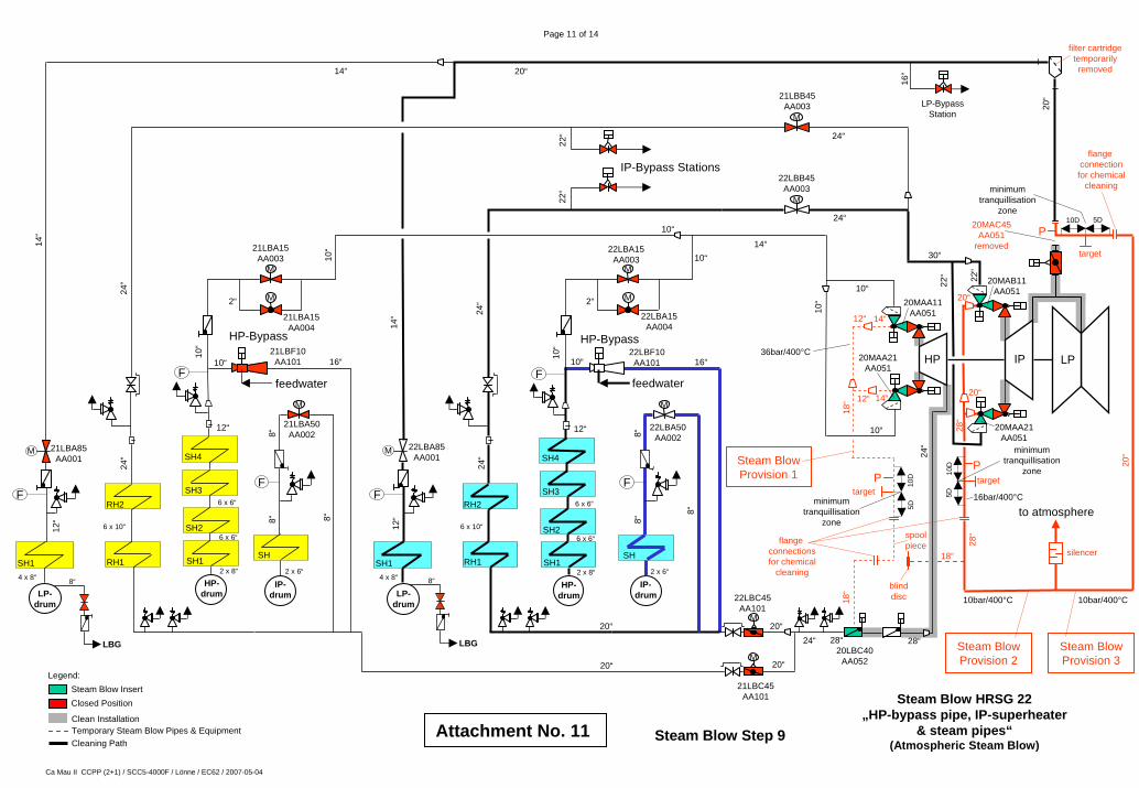
Page 11 of 14
HP-Bypass
M
M
10“
2“
RH1
LP-drum
SH1
10“
LPIPHP
HP-Bypass
M
M2“
RH1
LP-drum
SH1
28“
M
M
24“
20“
M
M
IP-Bypass Stations
LP-BypassStation
24“
10“
14“10“
22“
30“
24“
24“
10“
24“
24“
14“
14“
14“
10“
feedwaterfeedwater
flangeconnectionsfor chemical
cleaning
18“ blind
disc
spoolpiece
12“
12“
18“
P
to atmosphere
silencer
Steam BlowProvision 2
Steam BlowProvision 3
target
target
minimumtranquillisation
zone
20“
28“
20“
20“
Steam BlowProvision 1
20“
M M
20“
16“
SH1
28“20“
22“
22“
target
16“ 16“10“10“
10D 5D
10D
5D
P
P
10D
5D
minimumtranquillisation
zone
minimumtranquillisation
zone
18“
flangeconnectionfor chemical
cleaning
10bar/400°C 10bar/400°C
16bar/400°C
36bar/400°C
SH2
F
SH3
SH4
6 x 6“
2 x 8“
6 x 6“
12“
10“
SH2
F
SH3
SH4
6 x 6“
2 x 8“
6 x 6“
12“
10“
HP-drum
SH1
HP-drum
SH1
4 x 8“
F
12“
F
12“
4 x 8“
LBG LBG
8“ 8“
F
SH
M
IP-drum
8“
2 x 6“
8“
F
SH
M
IP-drum
8“
2 x 6“
8“ 8“
8“
20“
20“
RH2
Attachment No. 11
6 x 10“
24“
RH2
6 x 10“
24“
14“
14“
28“
Legend:Steam Blow InsertClosed Position
Clean InstallationTemporary Steam Blow Pipes & EquipmentCleaning Path
filter cartridgetemporarilyremoved
22“
Steam Blow Step 9
Steam Blow HRSG 22„HP-bypass pipe, IP-superheater
& steam pipes“(Atmospheric Steam Blow)
21LBA85AA001
21LBA15AA003
21LBF10AA101
21LBA50AA002
21LBA15AA004
22LBA85AA001
22LBA15AA003
22LBA15AA004
22LBF10AA101
22LBA50AA002
22LBC45AA101
21LBC45AA101
20LBC40AA052
22LBB45AA003
21LBB45AA003
20MAA11AA051
20MAA21AA051
20MAB11AA051
20MAA21AA051
20MAC45AA051
removed
Ca Mau II CCPP (2+1) / SCC5-4000F / Lönne / EC62 / 2007-05-04

Page 12 of 14
HP-Bypass
M
M
10“
2“
RH1
LP-drum
SH1
10“
LPIPHP
HP-Bypass
M
M2“
RH1
LP-drum
SH1
28“
M
M
24“
20“
M
M
IP-Bypass Stations
LP-BypassStation
24“
10“
14“10“
22“
30“
24“
24“
10“
24“
24“
14“
14“
14“
10“
feedwaterfeedwater
flangeconnectionsfor chemical
cleaning
18“ blind
disc
spoolpiece
12“
12“
18“
P
to atmosphere
silencer
Steam BlowProvision 2
Steam BlowProvision 3
target
target
minimumtranquillisation
zone
20“
28“
20“
20“
Steam BlowProvision 1
20“
M M
20“
16“
SH1
28“20“
22“
22“
target
16“ 16“10“10“
10D 5D
10D
5D
P
P
10D
5D
minimumtranquillisation
zone
minimumtranquillisation
zone
18“
flangeconnectionfor chemical
cleaning
10bar/400°C 10bar/400°C
16bar/400°C
36bar/400°C
SH2
F
SH3
SH4
6 x 6“
2 x 8“
6 x 6“
12“
10“
SH2
F
SH3
SH4
6 x 6“
2 x 8“
6 x 6“
12“
10“
HP-drum
SH1
HP-drum
SH1
4 x 8“
F
12“
F
12“
4 x 8“
LBG LBG
8“ 8“
F
SH
M
IP-drum
8“
2 x 6“
8“
F
SH
M
IP-drum
8“
2 x 6“
8“ 8“
8“
20“
20“
RH2
Attachment No. 12
6 x 10“
24“
RH2
6 x 10“
24“
14“
14“
28“
Legend:Steam Blow InsertClosed Position
Clean InstallationTemporary Steam Blow Pipes & EquipmentCleaning Path
filter cartridgetemporarilyremoved
22“
Steam Blow Step 10
Steam Blow HRSG 22„Cold reheat pipe, reheaters & hot reheat pipe“
(Atmospheric Steam Blow)
21LBA85AA001
21LBA15AA003
21LBF10AA101
21LBA50AA002
21LBA15AA004
22LBA85AA001
22LBA15AA003
22LBA15AA004
22LBF10AA101
22LBA50AA002
22LBC45AA101
21LBC45AA101
20LBC40AA052
22LBB45AA003
21LBB45AA003
20MAA11AA051
20MAA21AA051
20MAB11AA051
20MAA21AA051
20MAC45AA051
removed
Ca Mau II CCPP (2+1) / SCC5-4000F / Lönne / EC62 / 2007-05-04
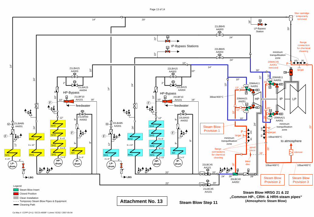
Page 13 of 14
HP-Bypass
M
M
10“
2“
RH1
LP-drum
SH1
10“
LPIPHP
HP-Bypass
M
M2“
RH1
LP-drum
SH1
28“
M
M
24“
20“
M
M
IP-Bypass Stations
LP-BypassStation
24“
10“
14“10“
22“
30“
24“
24“
10“
24“
24“
14“
14“
14“
10“
feedwaterfeedwater
flangeconnectionsfor chemical
cleaning
18“ blind
disc
spoolpiece
12“
12“
18“
P
to atmosphere
silencer
Steam BlowProvision 2
Steam BlowProvision 3
target
target
minimumtranquillisation
zone
20“
28“
20“
20“
Steam BlowProvision 1
20“
M M
20“
16“
SH1
28“20“
22“
22“
target
16“ 16“10“10“
10D 5D
10D
5D
P
P
10D
5D
minimumtranquillisation
zone
minimumtranquillisation
zone
18“
flangeconnectionfor chemical
cleaning
10bar/400°C 10bar/400°C
16bar/400°C
36bar/400°C
SH2
F
SH3
SH4
6 x 6“
2 x 8“
6 x 6“
12“
10“
SH2
F
SH3
SH4
6 x 6“
2 x 8“
6 x 6“
12“
10“
HP-drum
SH1
HP-drum
SH1
4 x 8“
F
12“
F
12“
4 x 8“
LBG LBG
8“ 8“
F
SH
M
IP-drum
8“
2 x 6“
8“
F
SH
M
IP-drum
8“
2 x 6“
8“ 8“
8“
20“
20“
RH2
Attachment No. 13
6 x 10“
24“
RH2
6 x 10“
24“
14“
14“
28“
Steam Blow HRSG 21 & 22„Common HP-, CRH- & HRH-steam pipes“
(Atmospheric Steam Blow)
Legend:Steam Blow InsertClosed Position
Clean InstallationTemporary Steam Blow Pipes & EquipmentCleaning Path
filter cartridgetemporarilyremoved
22“
21LBA85AA001
21LBA15AA003
21LBF10AA101
21LBA50AA002
21LBA15AA004
22LBA85AA001
22LBA15AA003
22LBA15AA004
22LBF10AA101
22LBA50AA002
22LBC45AA101
21LBC45AA101
20LBC40AA052
22LBB45AA003
21LBB45AA003
20MAA11AA051
20MAA21AA051
20MAB11AA051
20MAA21AA051
20MAC45AA051
removed
Steam Blow Step 11
Ca Mau II CCPP (2+1) / SCC5-4000F / Lönne / EC62 / 2007-05-04

HP-Bypass
M
M
10“
2“
RH1
LP-drum
SH1
10“
LPIPHP
HP-Bypass
M
M2“
RH1
LP-drum
SH1
28“
M
M
24“
20“
M
M
IP-Bypass Stations
LP-BypassStation
24“
10“
14“10“
22“
30“
24“
24“
10“
24“
24“
14“
14“
14“
10“
Attachment No. 14
feedwaterfeedwater
flangeconnectionsfor chemical
cleaning
18“ blind
disc
spoolpiece
12“
12“
18“
P
to atmosphere
silencer
Steam BlowProvision 2
Steam BlowProvision 3
target
target
minimumtranquillisation
zone
20“
28“
20“
20“
Steam BlowProvision 1
20“
M M
20“
16“
22LBA85AA001
SH1
22LBA15AA003
28“20“
22LBB45AA003
21LBB45AA003
22“
22“
target
16“ 16“10“10“
10D 5D
10D
5D
P
P
10D
5D
minimumtranquillisation
zone
minimumtranquillisation
zone
18“
flangeconnectionfor chemical
cleaning
Legend:Steam Blow InsertClosed Position
Clean InstallationTemporary Steam Blow Pipes & EquipmentCleaning Path
10bar/400°C 10bar/400°C
16bar/400°C
36bar/400°C
22LBA15AA004
SH2
F
SH3
SH4
6 x 6“
2 x 8“
6 x 6“
12“
10“
22LBF10AA101
SH2
F
SH3
SH4
6 x 6“
2 x 8“
6 x 6“
12“
10“
HP-drum
SH1
HP-drum
SH1
4 x 8“
F
12“
F
12“
4 x 8“
LBG LBG
8“ 8“
F
SH
M
22LBA50AA002
IP-drum
8“
2 x 6“
8“
F
SH
M
IP-drum
8“
2 x 6“
8“ 8“
8“
20“
20“
RH2
6 x 10“
24“
RH2
6 x 10“
24“
14“
14“
28“
Page 14 of 14
Steam Blow HRSG 21 & 22„LP-superheaters, single & common
LP-steam pipes“(Atmospheric Steam Blow)
filter cartridgetemporarilyremoved
22“
20MAA11AA051
20MAA21AA051
20MAB11AA051
20MAA21AA051
20MAC45AA051
removed
21LBA85AA001
21LBA15AA003
21LBF10AA101
21LBA50AA002
21LBA15AA004
22LBC45AA101
21LBC45AA101
20LBC40AA052
Steam Blow Step 12
Ca Mau II CCPP (2+1) / SCC5-4000F / Lönne / EC62 / 2007-05-04
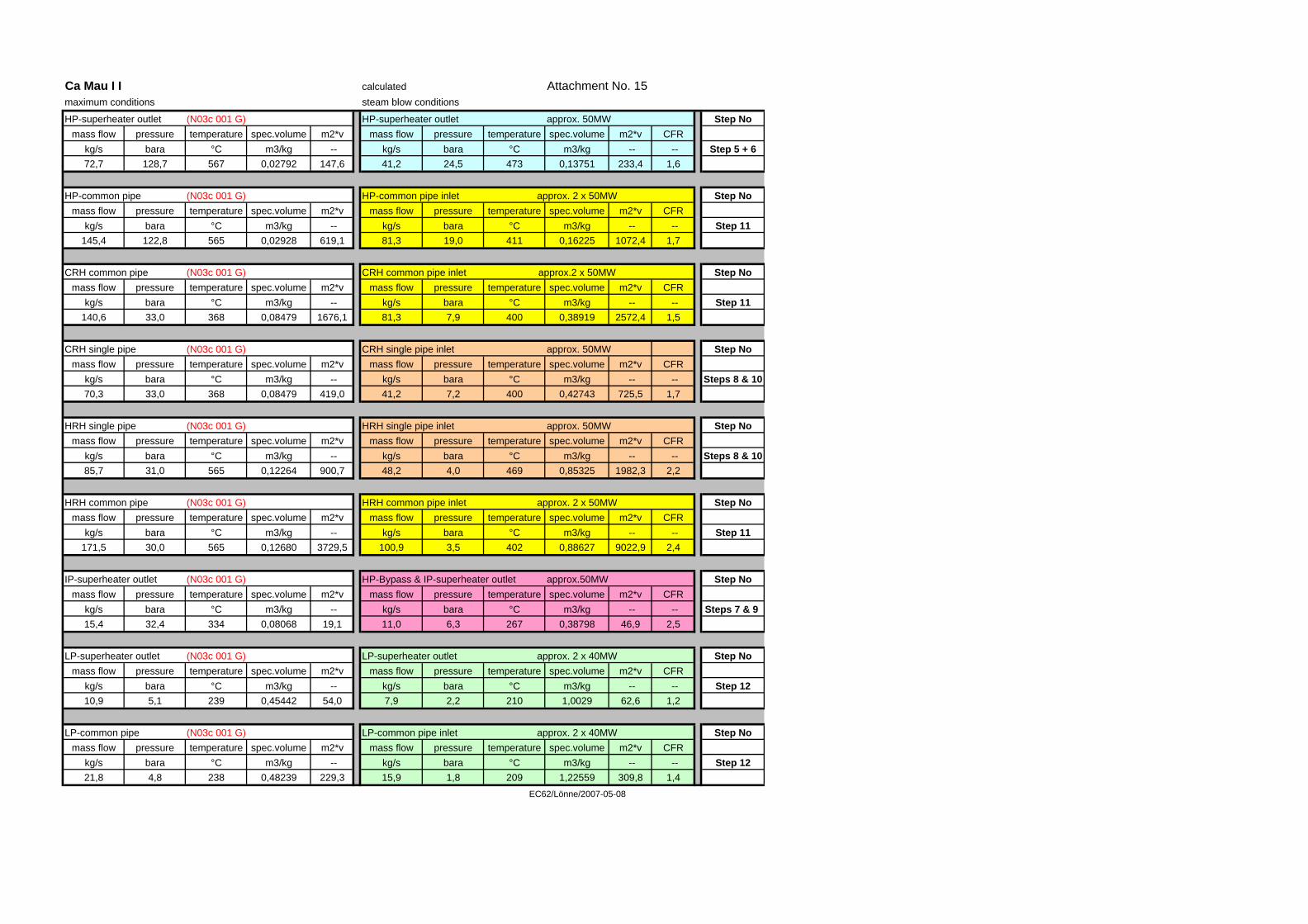
Ca Mau I I calculated Attachment No. 15maximum conditions steam blow conditions
HP-superheater outlet (N03c 001 G) HP-superheater outlet approx. 50MW Step Nomass flow pressure temperature spec.volume m2*v mass flow pressure temperature spec.volume m2*v CFR
kg/s bara °C m3/kg -- kg/s bara °C m3/kg -- -- Step 5 + 672,7 128,7 567 0,02792 147,6 41,2 24,5 473 0,13751 233,4 1,6
HP-common pipe (N03c 001 G) HP-common pipe inlet approx. 2 x 50MW Step Nomass flow pressure temperature spec.volume m2*v mass flow pressure temperature spec.volume m2*v CFR
kg/s bara °C m3/kg -- kg/s bara °C m3/kg -- -- Step 11145,4 122,8 565 0,02928 619,1 81,3 19,0 411 0,16225 1072,4 1,7
CRH common pipe (N03c 001 G) CRH common pipe inlet approx.2 x 50MW Step Nomass flow pressure temperature spec.volume m2*v mass flow pressure temperature spec.volume m2*v CFR
kg/s bara °C m3/kg -- kg/s bara °C m3/kg -- -- Step 11140,6 33,0 368 0,08479 1676,1 81,3 7,9 400 0,38919 2572,4 1,5
CRH single pipe (N03c 001 G) CRH single pipe inlet approx. 50MW Step Nomass flow pressure temperature spec.volume m2*v mass flow pressure temperature spec.volume m2*v CFR
kg/s bara °C m3/kg -- kg/s bara °C m3/kg -- -- Steps 8 & 1070,3 33,0 368 0,08479 419,0 41,2 7,2 400 0,42743 725,5 1,7
HRH single pipe (N03c 001 G) HRH single pipe inlet approx. 50MW Step Nomass flow pressure temperature spec.volume m2*v mass flow pressure temperature spec.volume m2*v CFR
kg/s bara °C m3/kg -- kg/s bara °C m3/kg -- -- Steps 8 & 1085,7 31,0 565 0,12264 900,7 48,2 4,0 469 0,85325 1982,3 2,2
HRH common pipe (N03c 001 G) HRH common pipe inlet approx. 2 x 50MW Step Nomass flow pressure temperature spec.volume m2*v mass flow pressure temperature spec.volume m2*v CFR
kg/s bara °C m3/kg -- kg/s bara °C m3/kg -- -- Step 11171,5 30,0 565 0,12680 3729,5 100,9 3,5 402 0,88627 9022,9 2,4
IP-superheater outlet (N03c 001 G) HP-Bypass & IP-superheater outlet approx.50MW Step Nomass flow pressure temperature spec.volume m2*v mass flow pressure temperature spec.volume m2*v CFR
kg/s bara °C m3/kg -- kg/s bara °C m3/kg -- -- Steps 7 & 9 15,4 32,4 334 0,08068 19,1 11,0 6,3 267 0,38798 46,9 2,5
LP-superheater outlet (N03c 001 G) LP-superheater outlet approx. 2 x 40MW Step Nomass flow pressure temperature spec.volume m2*v mass flow pressure temperature spec.volume m2*v CFR
kg/s bara °C m3/kg -- kg/s bara °C m3/kg -- -- Step 1210,9 5,1 239 0,45442 54,0 7,9 2,2 210 1,0029 62,6 1,2
LP-common pipe (N03c 001 G) LP-common pipe inlet approx. 2 x 40MW Step Nomass flow pressure temperature spec.volume m2*v mass flow pressure temperature spec.volume m2*v CFR
kg/s bara °C m3/kg -- kg/s bara °C m3/kg -- -- Step 1221,8 4,8 238 0,48239 229,3 15,9 1,8 209 1,22559 309,8 1,4
EC62/Lönne/2007-05-08
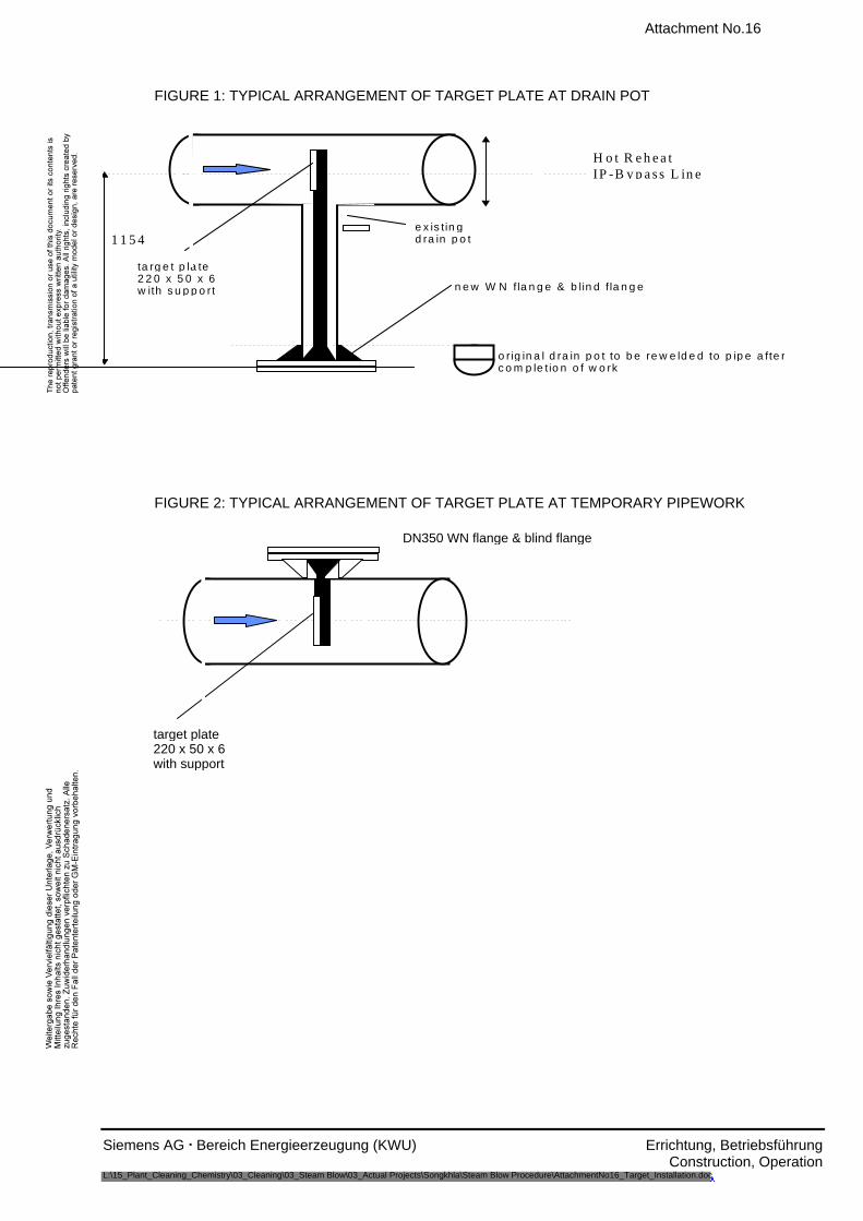
Attachment No.16
Siemens AG . Bereich Energieerzeugung (KWU) Errichtung, Betriebsführung Construction, Operation L:\15_Plant_Cleaning_Chemistry\03_Cleaning\03_Steam Blow\03_Actual Projects\Songkhla\Steam Blow Procedure\AttachmentNo16_Target_Installation.doc
FIGURE 1: TYPICAL ARRANGEMENT OF TARGET PLATE AT DRAIN POT
ta rg e t p la te2 2 0 x 5 0 x 6w ith s u p p o rt n e w W N f la n g e & b lin d f la n g e
e x is tin gd ra in p o t
o r ig in a l d ra in p o t to b e re w e ld e d to p ip e a fte rc o m p le t io n o f w o rk
H o t R e h e a tIP -B y p a s s L in e
1 1 5 4
FIGURE 2: TYPICAL ARRANGEMENT OF TARGET PLATE AT TEMPORARY PIPEWORK
target plate220 x 50 x 6with support
DN350 WN flange & blind flange