controller design methods for driving systems … design methods for driving systems based on...
TRANSCRIPT

Controller Design Methods for Driving Systems Based on Extensions of Symmetrical Optimum Method with DC and BLDC Motor Applications
Stefan Preitl*, Alexandra-Iulia Stînean**, Radu-Emil Precup***, Zsuzsa Preitl****, Emil M. Petriu*****,
Claudia-Adina Dragoş******, Mircea-Bogdan Rădac*******
*,**,***,******,******* Department of Automation and Applied Informatics, “Politehnica” University of Timisoara, Bd. V. Parvan 2, RO-300223 Timisoara, Romania (Tel: +40-256403224;
e-mail: stefan.preitl, alexandra-iulia.stinean, radu.precup, claudia.dragos, [email protected]) **** Siemens AG, Erlangen, Germany (e-mail: [email protected])
***** School of Electrical Engineering and Computer Science, University of Ottawa, 800 King Edward, Ottawa, ON, K1N 6N5 Canada (e-mail: [email protected])
Abstract: The paper gives design methods dedicated to speed control of Direct Current (DC) and Brushless Direct Current (BLDC) motors in the framework of servo systems. Two design approaches are offered for position and speed control of servo systems with inner current control loops. The PI and PID controllers in these approaches are tuned on the basis the Extended Symmetrical Optimum method and of the double parameterization of Symmetrical Optimum method. Cost-effective features are ensured by simple controller designs and easy implementations, and they are illustrated by means of a case study that includes simulation results. A two-degree-of-freedom interpretation is given. A BLDC motor application applied to mechatronic systems is presented.
Keywords: Design methods, PI and PID controllers, servo systems, simulation results, variable moment of inertia.
1. INTRODUCTION
The basic version of the Symmetrical Optimum method (SO-m) was given by Kessler (Kessler, 1958) for design situations that correspond to benchmark-type process models and to PI and PID controllers as representative one-degree-of-freedom (1-DOF) controllers. Using an adequately selected controller (Åstrom and Hägglund, 1995) in the open-loop transfer function (t.f.) )(0 sH , a double pole in the origin is ensured (by the SO-m):
)1()1(
)()()( 20
0Σ+
+=⋅=
sTssTk
sPsCsH c , (1)
where )(sC – the controller t.f. (PI(D) type) and )(sP – the controlled process t.f. Accordingly, the closed-loop t.f. with respect to the reference input r, )(sH r , can be expressed as
33
2210
10)(sasasaa
sbbsH r +++
+= . (2)
The “optimal” controllers’ parameters are obtained imposing the conditions
2231
2120 2 ,2 aaaaaa == . (3)
Consequently, the parameters of PI and PID controllers can be computed (and permanently updated online) by means of compact formulas. Many new tuning techniques based on the SO-m and on the Modulus Optimum method (MO-m) have been developed and used in industrial applications during the last years. The extension of SO-m with specification of
closed-loop resonant peak is proposed in (Loron, 1997). Many applications of SO-m and MO-m were discussed in (Quevedo and Escobet, 2000; Landau and Zito, 2006) and recently in (Scali et al., 2011). The robust speed control of electrical drives is analyzed in (Akpolat et al., 2000). A PID controller design with guaranteed gain and phase margins is proposed in (Ho and Wang, 2003). The tuning of PID controllers based on sensitivity margin specification is discussed in (Dormido and Morilla, 2004). The disturbance rejection performance of PID controllers is improved in (Vrančić et al., 2010). Attractive PID tuning rules for servo and regulation control problems are offered in (Arrieta et al., 2011). The design of two-degree-of-freedom (2-DOF) PI controllers based on events is given in (Sánchez et al., 2011).
Focused on obtaining better dynamics of the control structure, enhancement of robustness and enlarging the application areas, we have introduced recently two efficient control design techniques, the Extended Symmetrical Optimum method (ESO-m) (Preitl and Precup, 1999) and the Double Parameterization of the Symmetrical Optimum method (2p-SO-m) (Preitl, 2008) described in Section 2. The methods allow the online computation of controllers’ parameters for a maximum guaranteed phase margins (including the case of variable parameters in )(sP ), and have practical importance in the design of robust speed controllers (Preitl et al., 2002).
The presented design techniques have also various subsequent extensions: versions 2-DOF PID structures, sliding-mode PI controllers, PI-fuzzy controllers, structures with switching control algorithms. These techniques are
IFAC Conference on Advances in PID Control PID'12 Brescia (Italy), March 28-30, 2012 WePS.6

exemplified on Brushless Direct Current motor (BLDC-m) and also on DC motor (DC-m) servo systems characterized by Variable Moment of Inertia (VMI) where the use of controllers adapted to the operating point is necessary; they can be applied easily to other mechatronic systems (Isserman, 2005; Scali et al., 2011).
The paper is structured as follows: a short overview, some particularities and performance improvements concerning the ESO-m and the 2p-SO-m are presented in Section 2. Section 3 gives connections and interpretation details related to 2-DOF PI(D) controllers. Section 4 presents a case study concerning a low-power servo system application with BLDC motor. Section 5 is dedicated to the concluding remarks.
2. DESIGN METHODS, PERFORMANCE IMPROVEMENTS AND IMPLEMENTATION ISSUES
The ESO-m and the 2p-SO-m are generalized forms of SO-m. They are recommended mainly in three cases presented as follows.
The first case, specific to position control systems, is applied for processes with the t.f.s )(sP characterized by an integral component (benchmark-type forms):
) 1()(
Σ+=
Tssk
sP P , (4)
) 1)( 1()(
1TsTssk
sP P
++=
Σ
, (5)
where Pk is the process gain, 1T is the mechanical time constant, ΣT is the small time constant (electrical plus additional time constants), and Σ>> TT1 .
The second case refers to speed control applications, i.e., for processes with the t.f.s )(sP without integral components:
) 1)( 1()(
1TsTsk
sP P
++=
Σ
, (6)
) 1)( 1)( 1()(
21 TsTsTsk
sP P
+++=
Σ
, (7)
where Σ>> TT1 and Σ>>> TTT 21 . The t.f.s expressed in (6) and (7) are valid if the condition Σ> TT 41 is fulfilled. This condition occurs in modeling of BLDC-ms (similar to DC-ms) using a simplified t.f. to ensure a factorization of denominator polynomial in the mechanical time constant and electrical (and small) time constant. The parameters Pk and
1T can be time-variable in many applications (Grimble and Hearns, 1999).
The third case corresponds to time-variable reference input speed control structures (CSs), where the applications require small control errors and the presence of a second integral component ( 20 =q in Table 1) in the controller t.f. (and, finally, in )(0 sH ). 0q in Table 1 is the number of integral (I) components in )(0 sH , the subscript ∞ associated to a certain
variable points out the steady-state value of that variable, ∞y is the steady-state value of controlled output y, and ∞e is the steady-state value of control error e.
Table 1. Steady-state values of output and of control error for different values of 0q
∞y ∞e
)(sr 00 =q 10 =q 20 =q 00 =q 10 =q 20 =q
∞rs1
∞+r
kk
0
0
1 ∞⋅ r1 ∞⋅ r1 ∞+
rk01
1 ∞⋅ r0
∞⋅ r0
∞rs2
1 ∞ ∞ ∞ ∞ ∞rk 0
1 ∞⋅ r0
In the first two cases all situations given in Table 1 show that an 1-DOF PI or PID controller is used. The extension of the controller with a second I component is recommended in the third case; in such cases the controller is characterized by an is I+PI(D) structure, and an Anti-Windup-Reset (AWR) measure is recommended to be implemented in both I components as shown in Fig. 1. The given double circuit structure for the AWR is relatively simple, and it can provide good performance for variable reference inputs; so, the control error would tend to be of the same sign for a long time. Another more complicated multiple AWR structure is exemplified in (Boada et al., 2010).
Fig. 1. Double integrating PI(D) controller structure with double AWR measure (u – control signal).
The PI and PID controller t.f.s are given in (8) and (9), respectively:
) 1()( cc Tss
ksC += , (8)
) 1)( 1()( 'cc
c TsTss
ksC ++= , (9)
where ck is the controller gain, and cT and ' cT are the controller time constants.
The two extensions of SO-m presented as follows aim increased values of the phase margin, good (better) tracking performance and efficient disturbance rejection. Both methods are based on the following generalized form of SO-m optimization relations (3):
2231
2120 , aaaaaa =β=β , (10)
where β is the design parameter. The ESO-m can be applied in the first and third cases presented before, where the pole-
IFAC Conference on Advances in PID Control PID'12 Brescia (Italy), March 28-30, 2012 WePS.6

zero cancellation in )(0 sH (in the case of PID controllers,
1' TTc = ) simplifies the controller tuning to very simple and
clear relations. Applying (10) to (1) and (2) leads to
)1( 1)(
220 sTsTsTsH
ΣΣ
Σ
+βββ+
= , (11)
,))(1)(1(
1
1 1)(
22
2233
sTsTsTsT
sTsTsTsTsHr
ΣΣΣ
Σ
ΣΣΣ
Σ
β+β−β+β+β+
=
+β+ββ+βββ+
= (12)
and the controller tuning relations for PI(D) controllers are:
1'
2 , ,1 TTTT
Tkk cc
Pc =β=
ββ= Σ
Σ
. (13)
As result regarding the SO-m (a particular case of ESO-m for 4=β ), a controllable improvement of CS performance
indices as function of β is ensured. Fig. 2 illustrates the CS performance indices, as overshot σ1, normalized first settling time Σ= Ttt /ˆ
11 , normalized settling time Σ= Ttt ss /ˆ and phase margin mϕ , as functions of the design parameter β . The value of β is set by the designer, usually 169 <β< , according to the performance specifications.
Fig. 2. Specific performance indices versus β for ESO-m.
The ESO-m can guarantee a minimum value of the phase margin for processes with variable Pk or/and ΣT (but not only for these ones). The tuning conditions (13) allow the online controller tuning in the framework of adaptive control.
The 2p-SO-m is applicable to speed control of processes characterised by large differences between time constants, viz. Σ>> TT1 and Σ>>> TTT 21 (in the t.f.s (6) and (7)). This method is based on two design parameters, β (used in ESO-m) and 1/ TTm Σ= , and it ensures efficient rejection of disturbance rejection (for additive load-type disturbances applied to process input), improvement of mϕ , and good tracking performance. The tuning relations specific to the 2p-SO-m are (Preitl, 2008):
, ,)1(
)2(1 ,)1(1
'3
23
TTm
mmTTmTk
mk ccp
c =+
+β−+β=
ββ+
= ΣΣ
(14)
for 25.0<<m . Similarly to (13), the tuning conditions (14) allow online controller parameter tuning as function of the measured or calculated (variable) process parameters.
The main advantage of the 2p-SO-m in comparison with the classical MO-m concerns performance improvement for large differences between processes’ time constants. However, the CS performance can be improved in terms of different solutions. Fig. 3 illustrates several particular controller structures with non-homogenous dynamics with respect to the two inputs (Precup and Preitl, 1999). Each controller block can be characterized by its own t.f.s. The approach presented in Fig 3 permits also an easy 2-DOF interpretation of the design (Araki and Taguchi, 2003).
Fig. 3. Typical controller structures and particular forms of the modules.
A first solution concerns the appropriately designed reference filters with the t.f. )(sFr that can ensure efficient pole-zero cancellations. The following first version of reference filter compensates only the effect of the zero in (12):
sTsFr
Σβ+=
11)( . (15)
The CS is characterized in the relation yrr →→~ by the closed-loop system t.f. )(~ sH r which exhibits an oscillatory behaviour only for 9<β :
])(1)[1(1)(~
222/1 sTsTsTsHr
ΣΣΣ β+β−β+β+= . (16)
A second version of reference filter compensates the effects of the complex-conjugated poles and of the zero as well:
)1)(1())(1()(
22
ssTsTsTsTsF
fr +β+
β+β−β+=
Σ
ΣΣ . (17)
Consequently, the CS in the relation yrr →→~ exhibits an a-periodically behaviour:
)1)(1(1)(~
fr sTsT
sH+β+
=Σ
. (18)
In the case of 2p-SO-m, two parameters (β and m) are used to characterize the filters’ t.f.s (having the same structure).
3. 2-DOF CONTROLLER INTERPRETATIONS
The extended controller structure given in Fig. 3 can ensure efficient performance improvement and also a 2-DOF interpretation of the design. Three such 2-DOF CSs are presented in Fig. 4 and referred to as (Precup et al., 2009) the
IFAC Conference on Advances in PID Control PID'12 Brescia (Italy), March 28-30, 2012 WePS.6
reference input filter structure Fig. 4 (a), the feed-forward structure (Fig. 4 b), and the feedback structure (Fig. 4 c).
Fig. 4. Structures of 2-DOF controllers as extensions of 1-DOF controllers.
Some examples of connections between 2-DOF and extended 1-DOF controller structures are presented in Table 2, where: P – proportional, D – derivative, I – integral, L1(2) – first (second) order lag filter. The choice of a certain representation of the controller depends on the structure of the available (designed) main controller and on the adopted algorithmic design method.
Table 2. Connections between 2-DOF controllers and extended 1-DOF controller structures
Fig. 4 a F(s) - F(s)C(s) C(s) Remarks Fig. 4
b - CF C(s)–CF(s) C(s) -
Fig. 4 c - CP C*(s) C*(s)+CF(s) -
1α 2α - - (ref. channel) (feedback) -
0 0 1 0 PID PID 1-DOF 0 1 PDL2 DL1 PI PID
1 0 PD2 L2 P PIDL1 PID
1 1 PL2 PDL2 I PID
1-DOF with non-
homogenous
behaviour
1α 2α PID controller with pre-filtering (2-DOF controller)
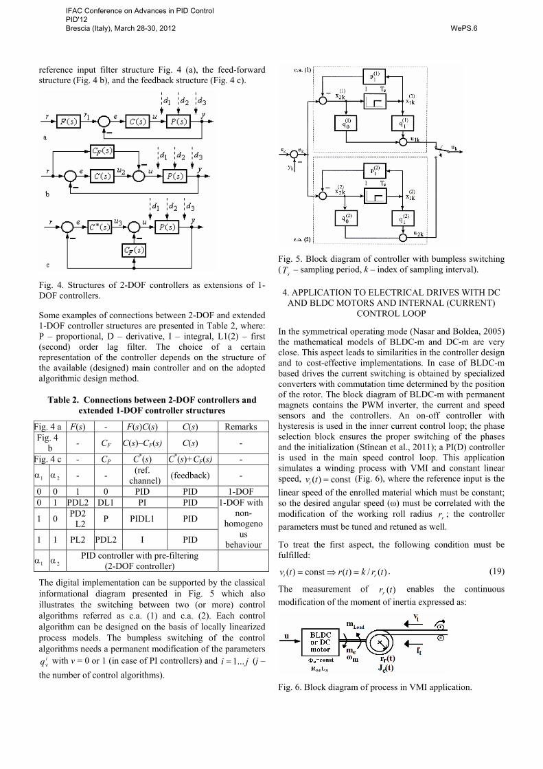
The digital implementation can be supported by the classical informational diagram presented in Fig. 5 which also illustrates the switching between two (or more) control algorithms referred as c.a. (1) and c.a. (2). Each control algorithm can be designed on the basis of locally linearized process models. The bumpless switching of the control algorithms needs a permanent modification of the parameters
iqν with ν = 0 or 1 (in case of PI controllers) and ji ...1= (j – the number of control algorithms).
Fig. 5. Block diagram of controller with bumpless switching ( sT – sampling period, k – index of sampling interval).
4. APPLICATION TO ELECTRICAL DRIVES WITH DC AND BLDC MOTORS AND INTERNAL (CURRENT)
CONTROL LOOP
In the symmetrical operating mode (Nasar and Boldea, 2005) the mathematical models of BLDC-m and DC-m are very close. This aspect leads to similarities in the controller design and to cost-effective implementations. In case of BLDC-m based drives the current switching is obtained by specialized converters with commutation time determined by the position of the rotor. The block diagram of BLDC-m with permanent magnets contains the PWM inverter, the current and speed sensors and the controllers. An on-off controller with hysteresis is used in the inner current control loop; the phase selection block ensures the proper switching of the phases and the initialization (Stînean et al., 2011); a PI(D) controller is used in the main speed control loop. This application simulates a winding process with VMI and constant linear speed, const)( =tvt (Fig. 6), where the reference input is the linear speed of the enrolled material which must be constant; so the desired angular speed (ω) must be correlated with the modification of the working roll radius rr ; the controller parameters must be tuned and retuned as well.
To treat the first aspect, the following condition must be fulfilled:
)(/)(const)( trktrtv rt =⇒= . (19)
The measurement of )(trr enables the continuous modification of the moment of inertia expressed as:
Fig. 6. Block diagram of process in VMI application.
IFAC Conference on Advances in PID Control PID'12 Brescia (Italy), March 28-30, 2012 WePS.6
)(21)( 4 trltJ re πρ= . (20)
The inner loop can be characterized generally by simplified benchmark-type second-order t.f.s connected to the operating point; the speed controller is a PI one, extended with an I component (to ensure good tracking properties). The resulting open-loop t.f. (1) has mc TTT == 1 (the mechanical time constant which is time-variable and must be compensated), cPkkk =0 , Σ>> TT1 . To ensure a desired phase margin, the open-loop gain 0k must be maintained constant and the permanent recalculation of ck according to (13) must be used (on the basis of the ESO-m).
A BLDC-m-based servo system with VMI characterized by the following parameters: p=2, Ra =1 Ω, La =0.02 H, VDC= 220 V, Je0= 0.005 kg m2, is considered. The inner control loop ensures a second-order (with lag) process behaviour characterized by (6) with 40=Pk , s 03.01 =T and
s 015.0=ΣT . The controlled parameters of BLDC-m, θ and lpm, were set to ensure that the motor can operate at any desired speed within -1s 3140 ≤ω≤ .
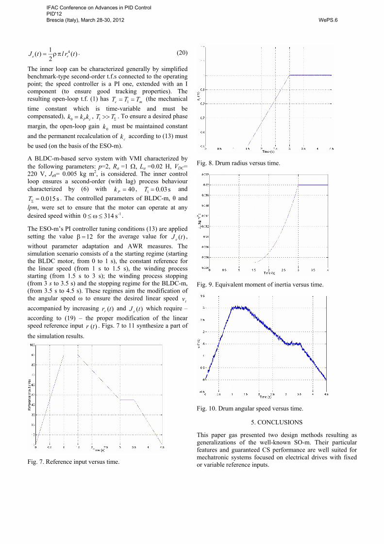
The ESO-m’s PI controller tuning conditions (13) are applied setting the value 12=β for the average value for )(tJ e , without parameter adaptation and AWR measures. The simulation scenario consists of a the starting regime (starting the BLDC motor, from 0 to 1 s), the constant reference for the linear speed (from 1 s to 1.5 s), the winding process starting (from 1.5 s to 3 s); the winding process stopping (from 3 s to 3.5 s) and the stopping regime for the BLDC-m, (from 3.5 s to 4.5 s). These regimes aim the modification of the angular speed ω to ensure the desired linear speed tv accompanied by increasing )(trr and )(tJ e which require – according to (19) – the proper modification of the linear speed reference input )(tr . Figs. 7 to 11 synthesize a part of the simulation results.
Fig. 7. Reference input versus time.
Fig. 8. Drum radius versus time.
Fig. 9. Equivalent moment of inertia versus time.
Fig. 10. Drum angular speed versus time.
5. CONCLUSIONS
This paper gas presented two design methods resulting as generalizations of the well-known SO-m. Their particular features and guaranteed CS performance are well suited for mechatronic systems focused on electrical drives with fixed or variable reference inputs.
IFAC Conference on Advances in PID Control PID'12 Brescia (Italy), March 28-30, 2012 WePS.6

Fig. 11. Drum linear speed versus time.
A case study concerning a low-power servo application with BLDC-m and variable reference input has illustrated and validated the design methods. The real-time validation of our methods for this particular area of application coming from servo systems with VMI are in current testing on an industrial process emulator laboratory equipment.
ACKNOWLEDGEMENTS
This work was supported by a grant of the Romanian National Authority for Scientific Research, CNCS – UEFISCDI, project number PN-II-ID-PCE-2011-3-0109. It was also partially supported by the strategic grant POSDRU ID 77265 (2010) of the Ministry of Labour, Family and Social Protection, Romania, co-financed by the European Social Fund – Investing in People.
REFERENCES
Akpolat, Z.H., Asher, G.M., and Clare, J.C. (2000). A practical approach to the design of robust speed controllers for machine drives. IEEE Transactions on Industrial Electronics, 47 (2), 315-324.
Araki M. and Taguchi, H. (2003). Two-degree-of-freedom PID controllers. International Journal of Control, Automation, and Systems, 1 (4), 401-411.
Arrieta, O., Vilanova, R., and Visioli, A. (2011). PID tuning for servo/regulation control operation for unstable and integrating processes. Industrial and Engineering Chemistry Research, 50 (6), 3327-3334.
Åstrom, K.J. and Hägglund, T. (1995). PID Controllers Theory: Design and Tuning. Instrument Society of America, Research Triangle Park.
Boada, J., Prieur, C., Tarbouriech, S., Pittet C., and Chaurbonnel, C. (2010). Multi-saturation anti-windup structure for satellite control. Proceedings of 2010 American Control Conference, Baltimore, MD, USA, 5979-5984.
Dormido, S. and Morilla, F. (2004). Tuning of PID controllers based on sensitivity margin specification. Proceedings of 5th Asian Control Conference, Melbourne, Australia, 1, 486-491.
Grimble, M. J. and Hearns, G. (1999). Advanced control for hot rolling mills. In: P.-M. Frank (ed.), Advances in
Control: Highlights of ECC’99, 135-170. Springer-Verlag, London.
Ho, M.T. and Wang, H.S. (2003). PID controller design with guaranteed gain and phase margins. Asian Journal of Control, 5 (3), pp. 374-381.
Isserman, R. (2005). Mechatronic Systems. Fundamentals. Springer-Verlag, Berlin, Heidelberg, New York.
Kessler, C. (1958). Das Symetrische Optimum. Regelungstechnik, 6 (11-12), 395-400, 432-436.
Landau, I.D. and Zito, G. (2006). Digital Control Systems: Design, Identification and Implementation. Springer-Verlag, London.
Loron, L. (1997). Tuning of PID controllers by the non-symmetrical optimum method. Automatica, 33 (1), 103-107.
Nasar S.A. and Boldea, I. (2005). Electric Drives, 2rd edition. CRC Press, Taylor & Francis, New York.
Precup, R.-E. and Preitl, S. (1999). Development of some fuzzy controllers with non-homogenous dynamics with respect to the input channels meant for a class of systems. Proceedings of European Control Conference (ECC’99), Karlsruhe, Germany, 6 pp.
Precup, R.-E., Preitl, S., Petriu, E.M., Tar, J.K., Tomescu, M.-L., and Pozna, C. (2009). Generic two-degree-of-freedom linear and fuzzy controllers for integral processes. Journal of The Franklin Institute, 346 (10), 988-1003.
Preitl, S. and Precup, R.-E. (1999). An extension of tuning relations after symmetrical optimum method for PI and PID Controllers. Automatica, 35 (10), 1731-1736.
Preitl, S., Preitl, Z., and Precup, R.-E. (2002). Low cost fuzzy controllers for classes of second-order systems. Proceedings of 15th IFAC World Congress (b’02), Barcelona, Spain, paper index 416, 6 pp.
Preitl, Z. (2008). Model Based Design Methods for Speed Control Applications. PhD Thesis, Editura Politehnica Publishers, Timisoara.
Quevedo, J. and Escobet, T. (eds.) (2000). Preprints of IFAC PID’00 Workshop on Digital Control: Past, Present and Future of PID Control. Terrassa, Spain.
Sánchez, J., Visioli, A., and Dormido, S. (2011). A two-degree-of-freedom PI controller based on events. Journal of Process Control, 21 (4), 639-651.
Scali, C., Matteucci, E., Pestonesi, D., Zizzo, A., and Bartaloni, E. (2011). Experimental characterization and diagnosis of different problems in control valves. Preprints of 18th IFAC World Congress (IFAC 2011), Milano, Italy, 7334-7339.
Stînean, A.-I., Preitl, S., Precup, R.-E., Pozna, C., Dragoş, C.-A., and Rădac, M.-B. (2011): Speed and position control of BLDC servo systems with low inertia. Proceedings of 2nd International Conference on Cognitive Info-communications, Budapest, Hungary, 10 pp.
Vrančić, D., Strmčnik, S., Kocijan, J., and de Moura Oliveira, P.B. (2010). Improving disturbance rejection of PID controllers by means of the magnitude optimum method. ISA Transactions, 49 (1), 47-56.
IFAC Conference on Advances in PID Control PID'12 Brescia (Italy), March 28-30, 2012 WePS.6