cryogenic loading devices for materials science
TRANSCRIPT
Cryogenic Loading Devices for Materials Science & Engineering Studies at J-PARC
Stefanus Harjo1, Kazuya Aizawa1, Takuro Kawasaki1, Tatsushi Nakamoto2 Tsutomu Hemmi3 and Takaaki Iwahashi1 1 J-PARC Center, JAEA, Tokai, Ibaraki 319-1195, Japan. 2 Cryogenics Science Center, KEK, Tsukuba, Ibaraki 305-0801, Japan 3 Fusion Research Development Directorate, JAEA, Naka, Ibaraki 319-1106, Japan E-mail: [email protected] Abstract. TAKUMI, the engineering materials diffractometer in the MLF of J-PARC, has developed two unique SE devices working with functions of low temperature, load and strain: a 100 K cooling system for loading experiment and a cryogenic loading machine. The 100 K cooling system for loading experiment is a compact vacuum chamber equipped with loading specimen jigs, and can mount the standard loading machine of TAKUMI. The specimen jigs can be set in a temperature range of 77 K to 473 K by controlling the liquid nitrogen flow and heater power. The industrial superconducting materials society, however, requires a loading machine working at a superconducting temperature such below 10 K. The cryogenic loading machine has been developed for this purpose. This machine is designed to able to cool down sample area together with the load frame, and a 4 K GM cooler is chosen as the core of cooling system. This machine can be used for tensile test at temperatures down to 7 K and at loads up to 50 kN.
1. Introduction TAKUMI [1] is a time of flight (TOF) neutron diffractometer in the MLF of J-PARC [2], which is dedicated for engineering sciences. TAKUMI covers evaluation of strains or stresses inside engineering components, evaluation of microstructural evolutions during deformations and/or thermal processes, during manufacturing and/or during service, crystallographic investigation of small regions in engineering materials, and texture analysis. In the commissioning, the performances of TAKUMI were confirmed as follows. The best resolution Δd/d of 0.17% was achieved by collimating the incident beam (high resolution mode) [3]. The d-range at a single frame bandwidth, i.e. standard operation, was 0.05 nm – 0.27 nm [3]. This range is the optimum range for engineering materials like steels, aluminum alloys, and so on. The neutron incident flux measured using the Au foil at the sample position was the same with that simulated using the McStas [4] with TAKUMI optics configuration. The neutron incident fluxes (simulated at 1 MW operation) at the sample position for the high intensity and high resolution modes are 4.8 × 107 cm2 s-1 and 2.2 × 107 cm2 s-1, respectively. TAKUMI adopts an event data recording method, which enables data reduction during or after the measurement with manipulating detector position, TOF binning, collection time, and so on [5]. Figure 1 shows the current situation of TAKUMI. To make TAKUMI productive in basic engineering sciences and applications, development of various sample environment (SE) devices is an important issue. TAKUMI has developed many various SE devices and opened them to support the user programs. The SE devices and its specifications are listed in Table 1. Many of them have been already used in various experiments producing many publications. 1 To whom any correspondence should be addressed.
3.7.2
- 441 -
JAEA-Conf 2015-002

Figure 1. Current situation of TAKUMI.
Table 1. Sample environment devices in TAKUMI
Specifications Status Publication examples used each SE
Radial collimators Gauge widths: 5 mm, 2 mm, 1 mm Pair per each
Ready [6], [7]
Standard loading machine
Gear-type Ten. 50 kN, Comp. 30 kN Load, displ. or strain control
Ready [8], [9]
Furnace system for high temp loading
Added to standard loading machine Halogen lamp furnace Temperature up to 1273 K Vacuum or inert gas
Ready [10]
100 K cooling system for loading experiment
Added to standard loading machine Liquid nitrogen flow + heater Temp range: 80 K – 473 K
Ready [11]
Cryogenic loading machine
Gear-type with GM cooler Temperature down to 6 K Tension 50 kN Load, displ. or strain control
Ready [12]
Fatigue machine Hydraulic driving Tension-compression up to 50 kN Repetition up to 30 Hz
Under commissioning
High temp. loading machine for small specimen
Gear-type Tension-compression up to 25 kN Temperature up to 873 K Inert gas
Under commissioning
Dilatometer Halogen lamp furnace Temperature up to 1273 K Vacuum or inert gas
Ready [13], [14]
Eulerian cradle Texture measurement or 3-axial stress measurement
Ready [15]
Gandolfi camera Powder diffractions of textured samples
Ready [16]
These SE devices make TAKUMI not only as the neutron engineering diffractometer with high accuracy and high efficiency, but also covering a wide application area. A new SE device, so-called thermec-mastor, that was developed in a collaboration with the Elements Strategy Initiative for Structure Materials (ESISM) at Kyoto University, is also under commissioning. This SE device enables a rapid heating, a rapid cooling and a rapid deformation under vacuum or inert gas condition,
- 442 -
JAEA-Conf 2015-002

i.e., a simulation of thermo-mechanical treatment. This device will be also opened for general users when it is ready. In the present report, the designs of the 100 K cooling system for loading experiment and cryogenic loading machine, and the research examples used these devices will be briefly introduced.
2. 100 K cooling system for loading Studies on the mechanisms of strengthening behaviors and/or functions of engineering materials are not enough only at room temperature (RT). Deformation studies at low and high temperatures give us much useful information to understand the basic properties of materials, and also to confirm the stabilities at conditions in uses. In TAKUMI, the deformation studies at high temperatures up to 1273 K can be conducted using the standard loading machine combined with a furnace system, but deformation studies at temperatures close to 273 K need a different type of device. Moreover, many engineering materials are used or show their functions mainly in a temperature range of 100 K - 423 K. There are many types of cooling systems for providing low temperatures, which apply the liquid nitrogen, the liquid helium or the Gifford-McMahon (GM) cooler. TAKUMI paid attention on a cooling system for high-pressure studies [17], because this system was able to cool down the sample temperature quickly and the time needed to change the sample was relatively short. This system applied the liquid nitrogen flow to cool anvils in a Paris-Edinburgh high-pressure cell.
standard'loading'machine
Liq.'N2'dewar'(100'L)'
Transfer'tube
Figure 2. Illustration of 100 K cooling chamber for loading experiment.
Figure 3. The 100 K cooling system for loading experiment mounted the standard loading machine.
Figure 2 shows the design of compact vacuum chamber for low temperature loading experiment. The jigs can mount the standard loading machine. Thermal isolators are put in between the jigs and grips to shut off the heat input from the outside. The grips are covered by jackets for cooling and heating. The jackets are connected to the liquid nitrogen dewar using transfer tubes, and also to the diaphragm pumps using pipes via the gas-flow controllers. The pipes between the chambers and controllers are equipped with heaters to vaporize the liquid nitrogen. Resistant heaters are also put in the jacket to control the temperature and to heat the specimen above RT. The gas-flow controllers and the power of resistant heaters are further controlled using single loop controllers (SDC35, Azbil Corp.). The temperature controls are done on the jacket, while the temperatures in the specimen are only monitored. The temperatures in the jackets can be controlled from 77 K to 473 K. The procedure of changing specimen is simple (less than 3.6 ks) and time needed to reach the coolest temperature is short (less than 3.6 ks). As the first trial using this system, transformation-induced plasticity (TRIP) behavior in commercial JIS-SUS304 steel was investigated. Tensile loading experiments were conducted at three different temperatures, 295 K, 213 K and 113 K. The tensile tests were conducted in a step-load controlling manner with 300 s holding in the elastic region, and in a continuous manner (without any pause) with a constant crosshead speed at an initial strain rate of about 1.0×10⁻⁵s-1 in the plastic region. Meanwhile, the neutron diffraction measurement was performed continuously without any pause during tensile test. Figure 4 shows the nominal stress strain curves of SUS304 obtained from tensile loading tests at different temperatures. The tensile strength increases with the decreasing of loading test temperature. In loading tests at low temperatures (213 or 113 K), the tensile stresses decrease or are kept constant at
- 443 -
JAEA-Conf 2015-002

- 444 -
JAEA-Conf 2015-002

3. Cryogenic loading machine Engineering studies of industrial superconducting composites using neutron diffraction need deformation tests at temperatures much lower than 100 K, because the expression of superconductivity mostly requires ultra-low temperatures. The presence of strains in the superconducting phases in industrial superconducting materials like Nb3Sn composites is well known to affect the superconducting properties [19], and therefore to understand the internal strains is very important, particularly under its use conditions (less than 10 K). To answer this requirement, the cryogenic loading machine was developed in TAKUMI. ENGIN-X at ISIS has developed a cryogenic chamber for in situ neutron diffraction measurements during deformation tests at low temperatures [20]. The lowest temperature that can be realized by this device was about 30 K, though two GM coolers were used. This device was used by mounting on the standard loading machine of ENGIN-X, which is similar to the 100 K cooling system for loading experiment, described above. Therefore, a different design should be developed to achieve temperatures below 10 K.
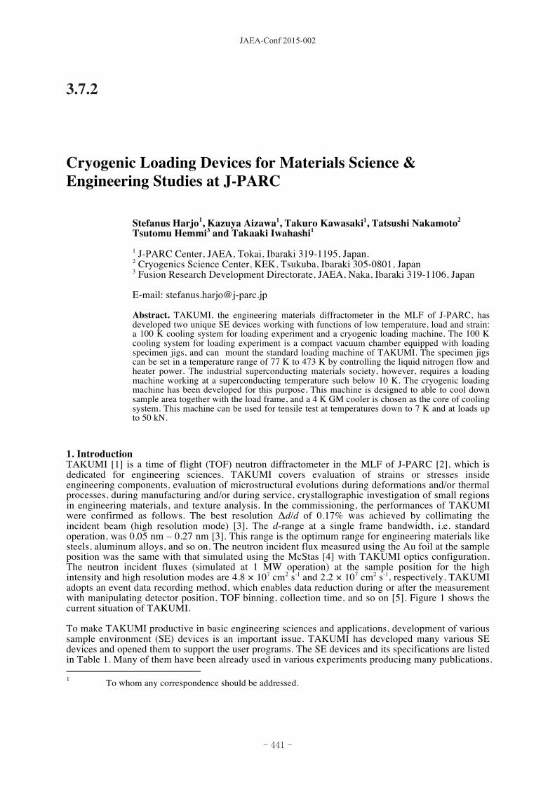
driving'side
Vac.pump
Load'frame
Driving''part
Vacuum'chamber
Compressor
Extensometer
Specimen
GM'stage
Thermocouple
Thermal'anchor
Load'cell'vacuum
Heater
Thermal'anchor
terminal'side
GM'cooler
Figure 6. Cryogenic loading machine developed at TAKUMI.
The principle of designing a cryogenic system having a very low achieving temperature, is to maximize the coefficient of performance. It can be changed thinking as minimizing the temperature difference between the high temperature and low temperature sides to minimize the heat input. A design that includes the loading frame to be evacuated and cooled, was decided to be manufactured after a heat calculation. Figure 6 shows the current situation of cryogenic loading machine. It is shown that, a GM cooler is applied in this system. The GM cooler (SRDK-415D-W71C, Sumitomo Heavy Industries, Ltd.), which has two stages of cooling cycles, is used. The GM stage of 4.2 K (1.5 W) is used to cool the sample area, and the GM stage of 50 K (35 W) to cool the load frame. The loading jig mounts a driving part located outside of the chamber that works up to 50 kN. A load cell with vacuum specification is put in between the loading jig and driving part. To confirm the cooling performance, a specimen of SUS304 was set in the system and a cooling test at the maximum power of the GM cooler was performed. The neutron diffraction measurement was conducted at the same time. Figure 7 shows the temperature change with respect to the time. The grips achieve 15 K within the first 9 ks. The temperatures are then gradually decreased for the next 28.8 ks, where the lowest temperature is 7 K. The diffraction patterns were analysed using Z-Rietveld software [21] to refine the lattice constants (a). The thermal strains during cooling were subsequently calculated using the expression (a – a0)/a0, where a0 represents the lattice constant at RT and at un-deformed state.
- 445 -
JAEA-Conf 2015-002

The coefficients of thermal expansion estimated from the thermal strains were similar to that reported in [22]. The in situ neutron diffraction during tensile test in the elastic region at 7 K was subsequently performed, and the lattice strains were found to be the same with those measured by the extensometer put on the specimen [13]. The temperature range of 7 K – 200 K (at the grips) can be controlled in this system.
7.2 14.4 21.6 28.8 36
50
0
100
150
200
250
300
0
Tempe
rature3(K
)
Time3(ks)
● GM3cooler3stage3□ Grip3at3driving3side3Δ Grip3at3terminal3side
Figure 7. The cooling performance of the cryogenic loading machine; the temperature change as a function of time.
Figure 8 shows the lattice strains in Nb3Sn phase measured from in situ neutron diffraction measurements during tensile tests of Rutherford Nb3Sn cables at RT and at about 10 K (low temperature: LT). Lattice strains were analysed in different (hkl). The lattice strains in as-reacted (AR) Nb3Sn Rutherford cable for the axial (longitudinal) direction at RT (RT) and at un-deformed state (so-called thermal strain), is compressive. The values of thermal strains become larger by cooling to LT, but the lattice strain responses to the applied stress are similar regardless of the temperature. Meanwhile, the lattice strains in the Rutherford Nb3Sn cable after a pre-bend treatment (PB) for the axial direction at RT and at un-deformed state, are relaxed to be close to zero. The changes of thermal strains due to cooling to LT in PB cable are small, and the lattice strain responses are also smaller than those in AR cables. The smaller thermal strains and smaller lattice strain responses to the applied stress are expected to improve the superconducting properties of the Rutherford Nb3Sn cable during its use in magnet applications.
Figure 8. Lattice strains measured during tensile deformation of Rutherford Nb3Sn cables. Lattice strains were analysed in different (hkl). AR: As-Reacted, PB: Pre-Bent treatment, RT: RT, LT: low temperature about 10 K
- 446 -
JAEA-Conf 2015-002

4. Summary TAKUMI is a neutron engineering diffractometer with high accuracy and high efficiency. Various kinds of sample environment devices are very important to cover wide engineering sciences. Two different types of cryogenic loading devices that cover different temperature ranges have been developed. (i) 100 K low temperature system for loading experiment: uses liquid nitrogen flow; only the sample area is cooled; the temperature range is 77 K – 473 K (in the specimen grips or the jackets); the procedure of changing specimen is simple; and the time needed to reach the coolest temperature is short (less than 3.6 ks). (ii) Cryogenic loading machine: uses GM cooler; the load frame is also evacuated and cooled; and the temperature range is 7 K – 200 K (at the specimen grips). Both devices are ready to be used to support user programs at TAKUMI.
5. References [1] Harjo S, Moriai A, Torii S, Suzuki H, Suzuya K, Morii Y, Arai M, Tomota Y, Akita K and
Akiniwa Y 2006 Mater. Sci. Forum 524-525 199 [2] Ikeda Y 2005 J. Nucl. Mater. 343 7 [3] Harjo S, Ito T, Aizawa K, Arima H, Abe J, Moriai A, Iwahashi T and Kamiyama T 2011 Mater.
Sci. Forum 681 443 [4] Lefmann K and Nielsen K 1999 Neutron News 10 20 [5] Ito T, Nakatani T, Harjo S, Arima H, Abe J, Aizawa K and Moriai A 2010 Mater. Sci. Forum
652 238 [6] Suzuki H, Harjo S, Abe J, Xu P, Aizawa K, Akita K 2013 Nucl. Instrum. Methods A 715 28 [7] Hemmi T, Harjo S, Nunoya Y, Kajitani H, Koizumi N, Aizawa K, Machiya S and Osamura K
2013 Supercond. Sci. Technol. 26 084002 [8] Morooka S, Sato N, Ojima M, Harjo S, Adachi Y, Tomota Y and Umezawa O 2011 IJAE 2 361 [9] Aizawa K, Gong W, Harjo S, Abe J, Iwahashi T and Kamiyama T 2013 Mater. Trans. 54 1083 [10] Harjo S, Ito T, Gong W, Suzuki H and Aizawa K 2011 CAMP-ISIJ 24 1121 [11] Harjo S, Kawasaki T, Gong W, Aizawa K and Iwahashi T JPS Conf. Proc. accepted [12] Yamaguchi T, Fukuda T, Kakeshita T, Harjo S and Nakamoto T 2014 Appl. Phys. Lett. 104
231908 [13] Jin X, Nakamoto T, Harjo S, Hemmi T, Umeno T, Ogitsu T, Yamamoto A, Sugano M, Aizawa
K, Abe J, Gong W and Iwahashi T 2013 Rev. Sci. Instrum. 84 063106 [14] Osamura K, Machiya S, Tsuchiya Y, Suzuki H, Shobu T, Sato M, Harjo S, Miyashita K,
Wadayama Y, Ochiai S and Nishimura A 2013 Supercond. Sci. Technol. 26 094001 [15] Gong W, Aizawa K, Harjo S, Abe J, Iwahashi T and Kamiyama T 2013 Mater. Trans. 54 974 [16] Xu P, Harjo S, Ito T, Gong W, Suzuki H, Akita K, Suzuki T, Tomota Y and Lutterotti L JPS
Conf. Proc. accepted [17] Gong W, Tomota Y, Harjo S, Su Y H and Aizawa K 2015 Acta mater. 85 243 [18] Komatsu K, Moriyama M, Koizumi T, Nakayama K, Kagi H, Abe J and Harjo S 2013 High
Pressure Res. 33 208 [19] Ekin J W 1980 Cryogenics 20 611 [20] Oliver E, Evans B, Chowdhury M, Major R, Kirichek O and Bowden Z 2008 Meas. Sci.
Technol. 19 034019 [21] Oishi R, Yonemura M, Nishimaki Y, Torii S, Hoshikawa A, Ishigaki T, Morishima T, Mori K
and Kamiyama T 2009 Nucl. Instrum. Methods A 600 94 [22] Collocott S J and White G K 1986 Cryogenics 26 402
Acknowledgments Authors wish to acknowledge staffs of the MLF of J-PARC for assistance or encouragement in these developments, Drs. S. Awaji, K. Takahashi of Tohoku University and X. Jin of RIKEN for valuable discussions. These works got partially financial supports from JSPS grants (KAKENHI No. 23109003, 26600146 and 26289264).
- 447 -
JAEA-Conf 2015-002