cs-400 service manual
DESCRIPTION
Manual de Servicio Analizador Bioquímico DIRUI CS 400TRANSCRIPT
1
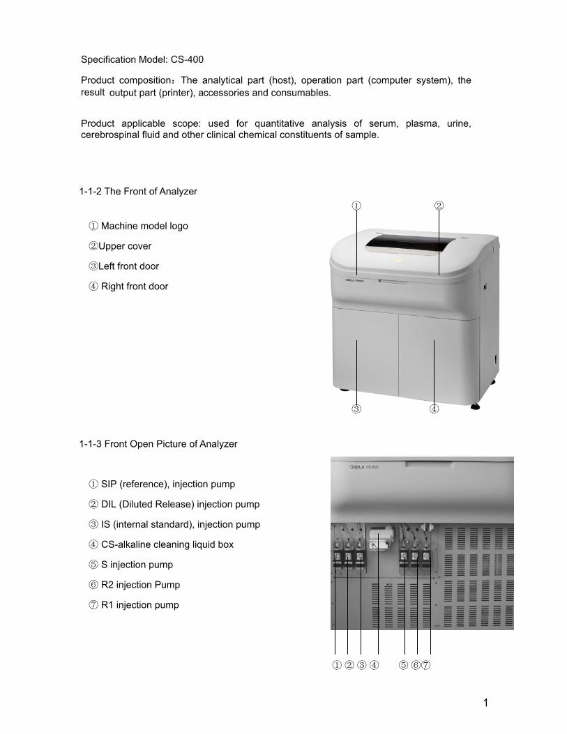
1-1-2 The Front of Analyzer ① ②
① Machine model logo
②Upper cover
③Left front door
④ Right front door
③ ④
1-1-3 Front Open Picture of Analyzer
① SIP (reference), injection pump
② DIL (Diluted Release) injection pump
③ IS (internal standard), injection pump
④ CS-alkaline cleaning liquid box
⑤ S injection pump
⑥ R2 injection Pump
⑦ R1 injection pump
①
②
③
④ ⑤
⑥⑦
Specification Model: CS-400
Product composition:The analytical part (host), operation part (computer system), the result output part (printer), accessories and consumables.
Product applicable scope: used for quantitative analysis of serum, plasma, urine, cerebrospinal fluid and other clinical chemical constituents of sample.

2
1-1-4 The back of analyzer Power entrance ①
RS232 interface ②
left back cover board③
cooling fan ④
light liquid outlet ⑤
right back cover board ⑥
purified water entrance ⑦
concentrated liquid waste outlet ⑧
concentrated waste liquid level sensor interface⑨
1-1-5 The Top of Analyzer ① sampling mechanism
② reaction cup cleaning mechanism
③ reaction disk mechanism
④ reaction bath liquid detection ⑤ R1 stirring mechanism
⑥ R1 reagent adding mechanism
⑦ probe cleaning reagent groove
⑧ R1 reagent disk
⑨ sample disk rotating indicator
⑩ sample disk inner refrigerated cover
⑾ sample disk
⑿ R2 reagent adding mechanism
⒀ R2 stirring mechanism
⒁ R2 reagent disk
① ② ③ ④ ⑤ ⑥ ⑦ ⑧ ⑨
① ② ③ ④ ⑤ ⑥ ⑦ ⑧
⑨ ⑩ ⑾ ⑿ ⒀ ⒁

3
1-1-6 The Right of Analyzer
① Analytical unit switches
(not including refrigeration power supply)
② refrigeration power supply indicator(green)
③ main power supply(breaker)
④power indicator(red)
① ② ③ ④
4
1.2 Analytical Unit Composition
CS-400 auto-chemistry analyzer working speed means the one at which it reaches constant speed 400 tests / hour of single / double-reagent item, whose working period is 9 seconds. Instrument overall structure adopts the "4 -disk + three-probe + two-stirring rod", specifically, a sample disk, one reaction disk, two reagent disks, 2 reagent probes for adding R1 and R2 respectively, a sample probe for sampling, 2 stirring rods for mixing R1,R2 respectively. "Grating + diode array" approach is adopted in optical measurement mechanism for real-time optical collection of reaction cup. The rinsing mechanism 7-stop 11-step automatically rinsing the reaction cup is carried out in test process.
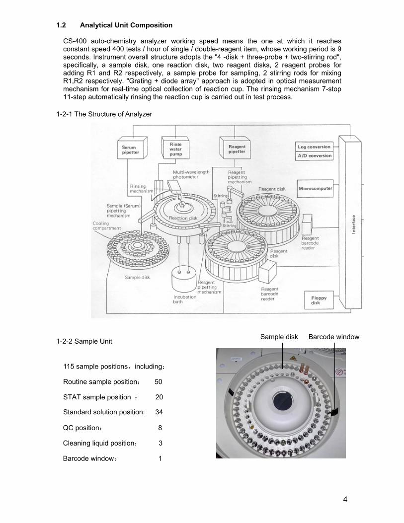
1-2-1 The Structure of Analyzer
1-2-2 Sample Unit
115 sample positions,including:
Routine sample position: 50
STAT sample position : 20
Standard solution position: 34
Sample disk Barcode window
QC position: 8
Cleaning liquid position: 3
Barcode window: 1
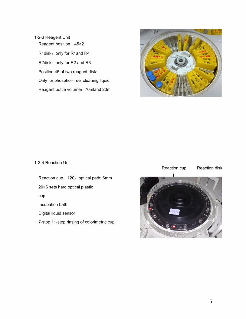
Only for phosphor-free cleaning liquid
5
1-2-3 Reagent Unit Reagent position:45×2
R1disk:only for R1and R4
R2disk:only for R2 and R3
Position 45 of two reagent disk:
Reagent bottle volume:70mland 20ml
1-2-4 Reaction Unit
Reaction cup:120,optical path: 6mm
20×6 sets hard optical plastic
cup
Incubation bath
Digital liquid sensor
7-stop 11-step rinsing of colorimetric cup
Reaction cup Reaction disk
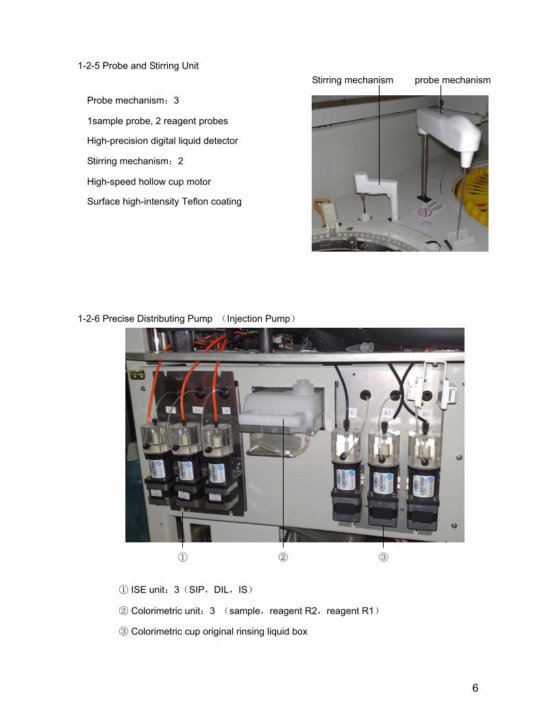
Stirring mechanism probe mechanism
6
1-2-5 Probe and Stirring Unit
Probe mechanism:3
1sample probe, 2 reagent probes
High-precision digital liquid detector
Stirring mechanism:2
High-speed hollow cup motor
Surface high-intensity Teflon coating
1-2-6 Precise Distributing Pump (Injection Pump)
① ② ③
① ISE unit:3(SIP,DIL,IS)
② Colorimetric unit:3 (sample,reagent R2,reagent R1)
③ Colorimetric cup original rinsing liquid box
7
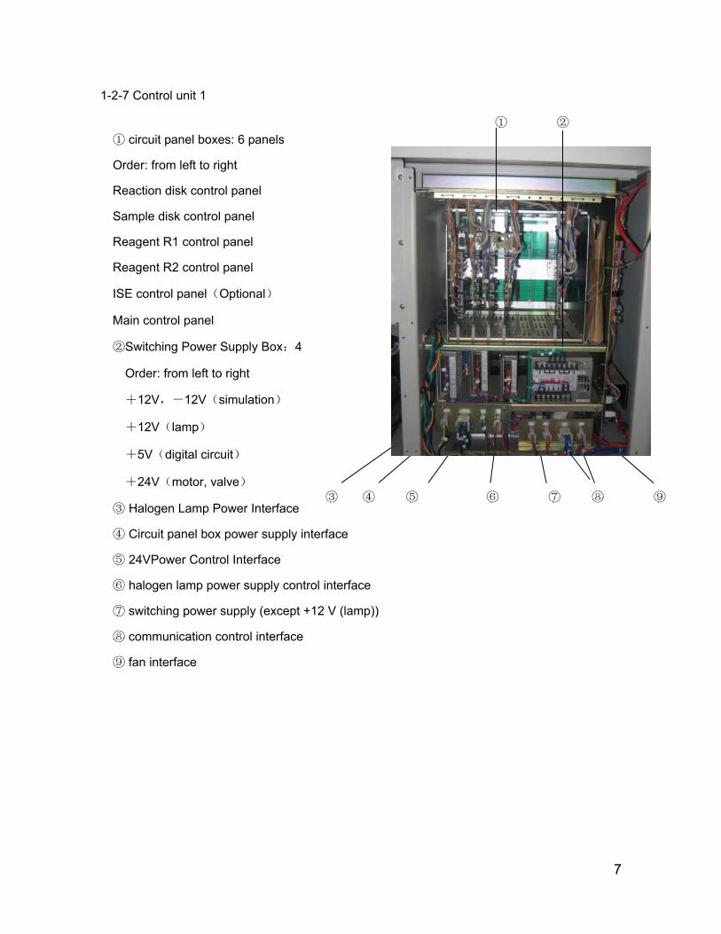
1-2-7 Control unit 1
circuit panel boxes: 6 panels①
Order: from left to right
Reaction disk control panel
Sample disk control panel
Reagent R1 control panel
Reagent R2 control panel
ISE control panel(Optional)
Main control panel
②Switching Power Supply Box:4
Order: from left to right
+12V,-12V(simulation)
+12V(lamp)
+5V(digital circuit)
+24V(motor, valve)
③ Halogen Lamp Power Interface
④ Circuit panel box power supply interface
⑤ 24VPower Control Interface
⑥ halogen lamp power supply control interface
⑦ switching power supply (except +12 V (lamp))
⑧ communication control interface
⑨ fan interface
③ ④ ⑤ ⑥ ⑦ ⑧ ⑨
① ②
8
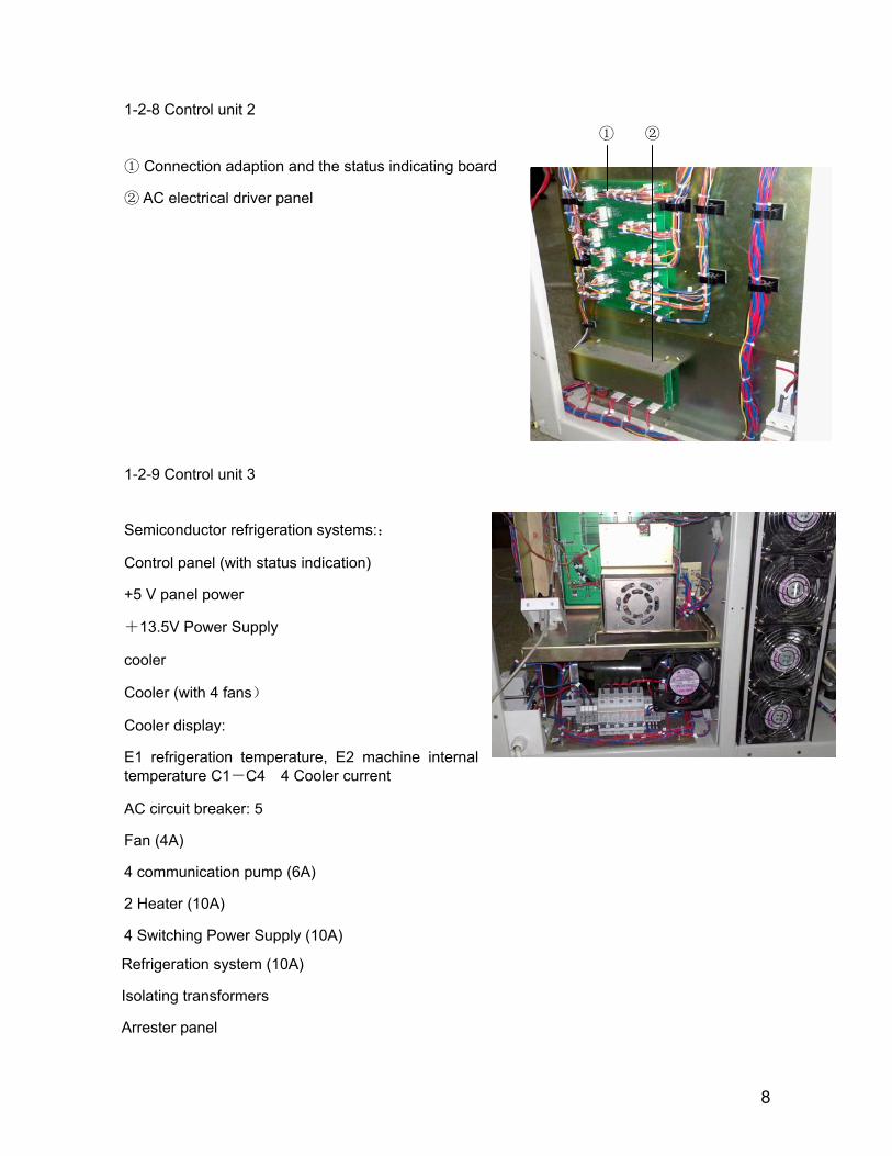
1-2-8 Control unit 2 ① ②
① Connection adaption and the status indicating board
② AC electrical driver panel
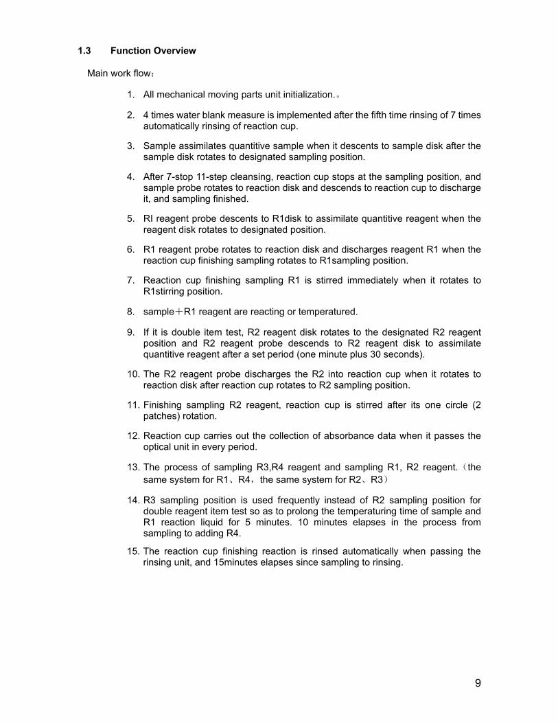
1-2-9 Control unit 3
Semiconductor refrigeration systems::
Control panel (with status indication)
+5 V panel power
+13.5V Power Supply
cooler
Cooler (with 4 fans)
Cooler display:
E1 refrigeration temperature, E2 machine internal temperature C1-C4 4 Cooler current
AC circuit breaker: 5
Fan (4A)
4 communication pump (6A)
2 Heater (10A)
4 Switching Power Supply (10A)
Refrigeration system (10A)
Isolating transformers
Arrester panel
9
1.3 Function Overview
Main work flow:
1. All mechanical moving parts unit initialization.。
2. 4 times water blank measure is implemented after the fifth time rinsing of 7 times automatically rinsing of reaction cup.
3. Sample assimilates quantitive sample when it descents to sample disk after the sample disk rotates to designated sampling position.
4. After 7-stop 11-step cleansing, reaction cup stops at the sampling position, and sample probe rotates to reaction disk and descends to reaction cup to discharge it, and sampling finished.
5. RI reagent probe descents to R1disk to assimilate quantitive reagent when the reagent disk rotates to designated position.
6. R1 reagent probe rotates to reaction disk and discharges reagent R1 when the reaction cup finishing sampling rotates to R1sampling position.
7. Reaction cup finishing sampling R1 is stirred immediately when it rotates to R1stirring position.
8. sample+R1 reagent are reacting or temperatured.
9. If it is double item test, R2 reagent disk rotates to the designated R2 reagent position and R2 reagent probe descends to R2 reagent disk to assimilate quantitive reagent after a set period (one minute plus 30 seconds).
10. The R2 reagent probe discharges the R2 into reaction cup when it rotates to reaction disk after reaction cup rotates to R2 sampling position.
11. Finishing sampling R2 reagent, reaction cup is stirred after its one circle (2 patches) rotation.
12. Reaction cup carries out the collection of absorbance data when it passes the optical unit in every period.
13. The process of sampling R3,R4 reagent and sampling R1, R2 reagent.(the same system for R1、R4,the same system for R2、R3)
14. R3 sampling position is used frequently instead of R2 sampling position for double reagent item test so as to prolong the temperaturing time of sample and R1 reaction liquid for 5 minutes. 10 minutes elapses in the process from sampling to adding R4.
15. The reaction cup finishing reaction is rinsed automatically when passing the rinsing unit, and 15minutes elapses since sampling to rinsing.
10
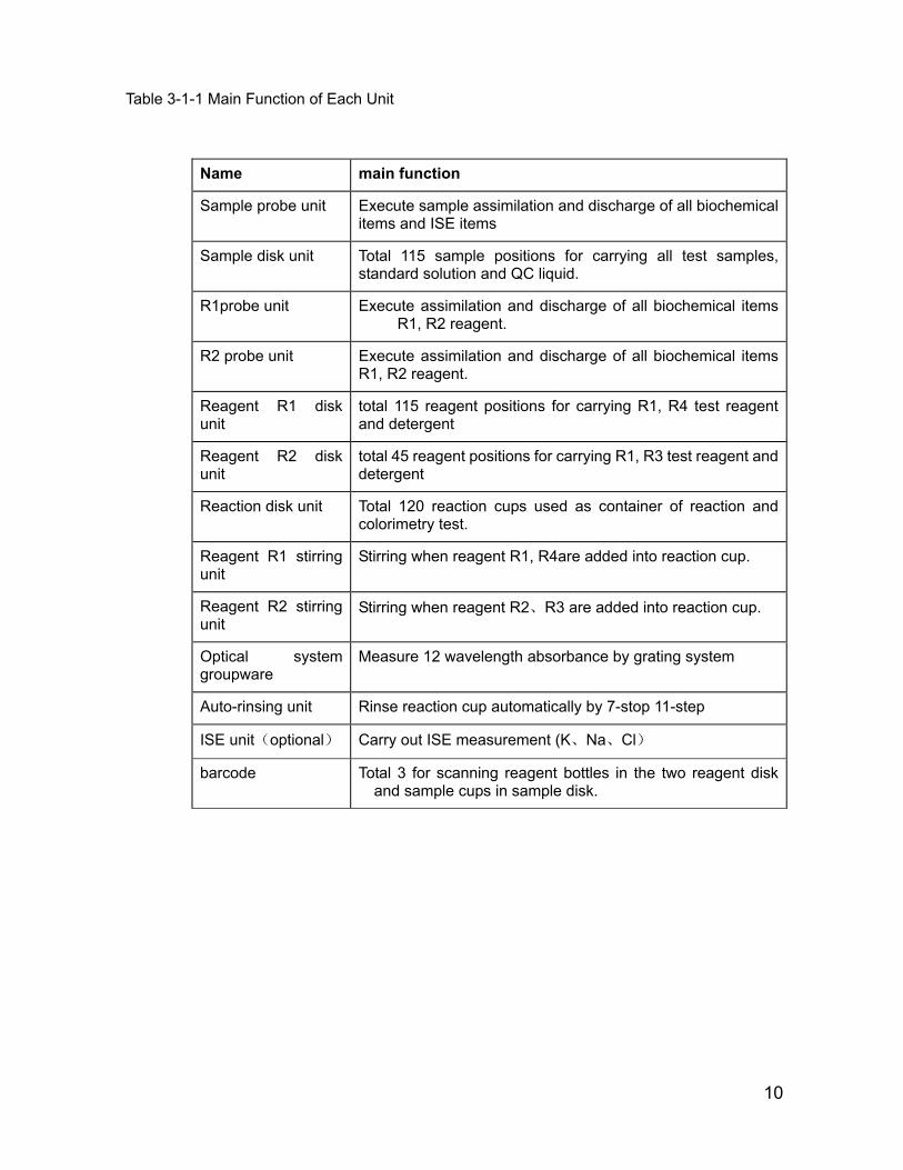
Table 3-1-1 Main Function of Each Unit
Name main function
Sample probe unit Execute sample assimilation and discharge of all biochemical items and ISE items
Sample disk unit Total 115 sample positions for carrying all test samples, standard solution and QC liquid.
R1probe unit Execute assimilation and discharge of all biochemical items R1, R2 reagent.
R2 probe unit Execute assimilation and discharge of all biochemical items R1, R2 reagent.
Reagent R1 disk unit
total 115 reagent positions for carrying R1, R4 test reagent and detergent
Reagent R2 disk unit
total 45 reagent positions for carrying R1, R3 test reagent and detergent
Reaction disk unit Total 120 reaction cups used as container of reaction and colorimetry test.
Reagent R1 stirring unit
Stirring when reagent R1, R4are added into reaction cup.
Reagent R2 stirring unit
Stirring when reagent R2、R3 are added into reaction cup.
Optical system groupware
Measure 12 wavelength absorbance by grating system
Auto-rinsing unit Rinse reaction cup automatically by 7-stop 11-step
ISE unit(optional) Carry out ISE measurement (K、Na、Cl)
barcode Total 3 for scanning reagent bottles in the two reagent disk and sample cups in sample disk.
11
Chapter 2 Instrument Installation
2.1 Installation Space Requirement:
To make sure the space of maintenance, operation and repair, please follow the instruction as below:
● Space between left (right) side of analyzer and the wall should ≥50cm ● Space between rear board of analyzer and the wall should ≥50cm ● Space in front of analyzer should≥100cm ● Make sure there is enough space for waste device and purified water equipment.
2.2 Power supply requirement:
● Power supply: ~220V, 50Hz
● Power: 2000 VA
● Circuit breaker: 250V, 20A
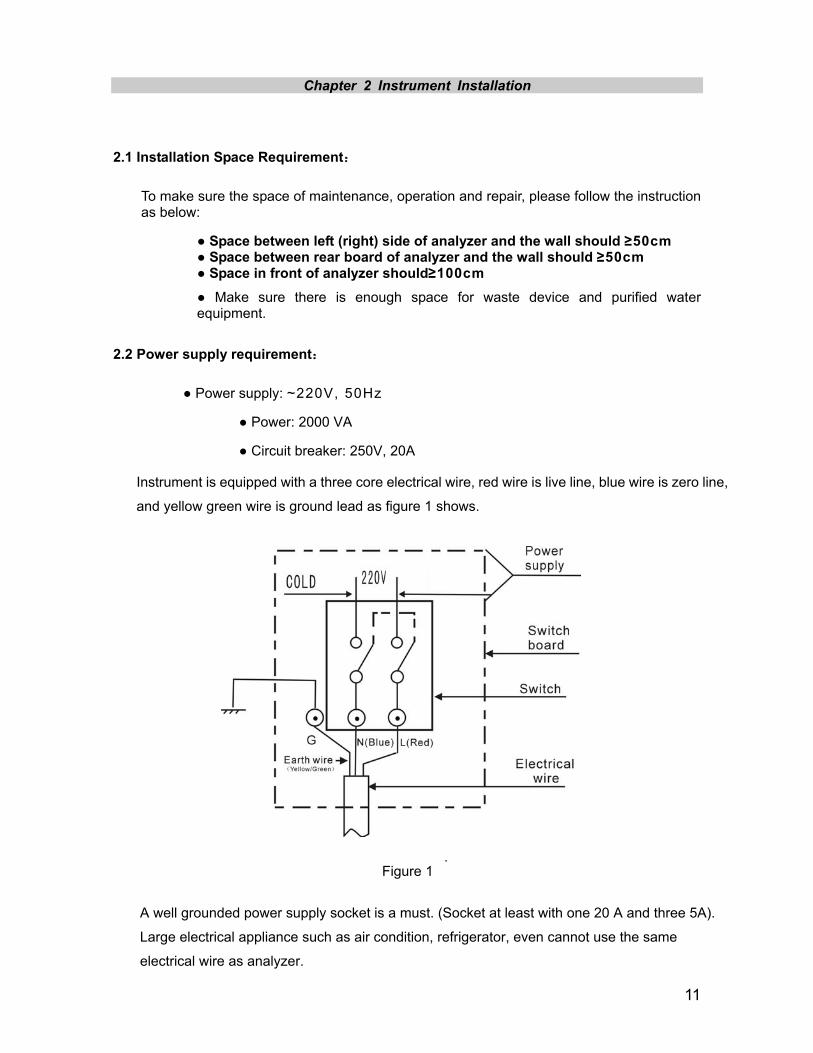
Instrument is equipped with a three core electrical wire, red wire is live line, blue wire is zero line,
and yellow green wire is ground lead as figure 1 shows.
Figure 1 i
A well grounded power supply socket is a must. (Socket at least with one 20 A and three 5A).
Large electrical appliance such as air condition, refrigerator, even cannot use the same
electrical wire as analyzer.
12
● Relative humidity: 40%~85%
● Atmospheric pressure: 76kPa~106kPa
● Environment should be with no dust, mechanical vibration, and noise source and power interference
● Do not put the analyzer in the vicinity of brush motor, flicker fluorescent tube and other constant on-off electrical equipment.
Hard and flat enough the ground should be to stand the instrument.
● Avoid direct sunlight, do not put the analyzer in front of heat source and wind source
Keep good ventilation of the instrument.
△! warning:
Normal running and accuracy of result can not be guaranteed if instrument works beyond
the requirements mentioned above. Please use air conditioner if the temperature or
humidity can not meet the requirement above.
The heat generated in the work process by the instrument will be emitted the rear of the
instrument, so good ventilation should be kept well and ventilation equipment can be
adopted if necessary, but direct air current is avoided, or inaccuracy of instrument test may
be caused.
4.2 2.4 Purified water equipment Requirement:
① water should be obtained from tap water pipe
② water conductivity should within 1uS/cm
③ water supply volume should reach 40L/h or more
④ The hydraulic pressure should within 49-343 Kpa
2.5 Instrument Installation Flow:
Make sure the installation place, space, electrical environment, installation room
temperature and purified water equipment can conform to requirements
Make sure instrument installation tools needed are complete and reagent and QC liquid are
enough.
Please check the prepared items according to packing list when open the package; please
write them down on the check report if any missing.
△! Warning:
Incorrect earthing may cause electric shock or instrument damage.
Input voltage should conform to requirement. 6KVA-line UPS power supply is advised.
2.3 Environment requirement
● Working environment: 15℃~32℃

13
Place instrument in applicable position, and mount with computer host, display and printer.
Connect water supply and waste liquid outlet equipment.
Adjust instrument level, and check whether the injection pump wires are loose or not after
open the left and right cover board of instrument.
Infuse CS-alkaline detergent into instrument rinsing box, and infuse CS-anti-bacterial
detergent into the 45th position of R1, R2 reagent disks.
Replenish cooling system water tank with purified water.
(a)Switch off the main power
(b)Demount instrument left front cover board as figure 2 shows:
(c)Unplug the cork of the two hoses connecting to cooling system water tank as figure 3 shows :
High water level hose
Low water level hose
14
(d)Infuse purified water into low water level hose till the purified water flows out of the
high level hose.
(e)Switch on the main power. After several minutes, continue to infuse purified water
into low water level hose till the purified water flows out of the high level hose again,
requiring 3L water.
(f)Replug the rubber cork and mount the left front cover board of the instrument.
Check whether power supply and data wires are connected.
Mount reagent probe, sample probe, reaction cup.
Check the up and down flexibility of reagent probe and sample probe.
Get through pure water machine, computer host and display and analytical unit power
supply, and enter CS auto-chemistry analyzer systematic application software. Initial user
name: 001, initial password: 001.
After enter software, follow the steps below in “Maintenance” interface.
(a)Injection pump exhaust
Execute injection pump exhaust to expel air in pipeline.
(b)Cleaning liquid pipeline exhaust
Executing irrigation cleaning liquid pipeline exhaust is infusing cleaning liquid into
pipeline to expel air in pipeline.
(c)Reagent probe horizontal check
Make sure reagent probe is right above reaction cup, rinsing groove and reagent bottle.
(d)sample probe horizontal check
Place a standard cup at position C8 in the sample disk outer track, middle track and
inner track respectively, and make sure the sample probe is above reaction cup, rinsing
groove, standard cup by implementing sample probe horizontal check.
15
(e)Stirring rod horizontal check
In order to make sure the stirring rod is above the reaction cup, rinsing groove.
(f)Mechanical movement check
Execute 20 times mechanical movement checks to make sure whether the washing
block of rinsing mechanism nozzle abrases the reaction cup or not and each
mechanism runs normally or not.
(g)Rinse reaction cup+ ISE
Select rinsing reaction cup in “Maintenance” interface, and execute rinsing reaction cup
+ ISE if ISE equipment is collocated.
(h)Light quantity check
Light quantity result should be attached to installation check report with its value no
more than 18000.
(i)Cup blank test
No. 1 cup blank value should be within 18000, and 2-120 reaction cup check value
should be within 18000 ±800.
2.6 Clinical item test
Edit chemical parameters; register reagent info.; testing rate assay ALT, point assay,
two-point rate BUN; calculate the difference of parameter and the result of test should be
attached to installation check report.
2.7 Train Medical Personnel。
2.8 Fill the Installation Check Report Detailedly.
Sample disk
16
Chapter 3 Performance and Test Flow
3.1 Main Performance Index
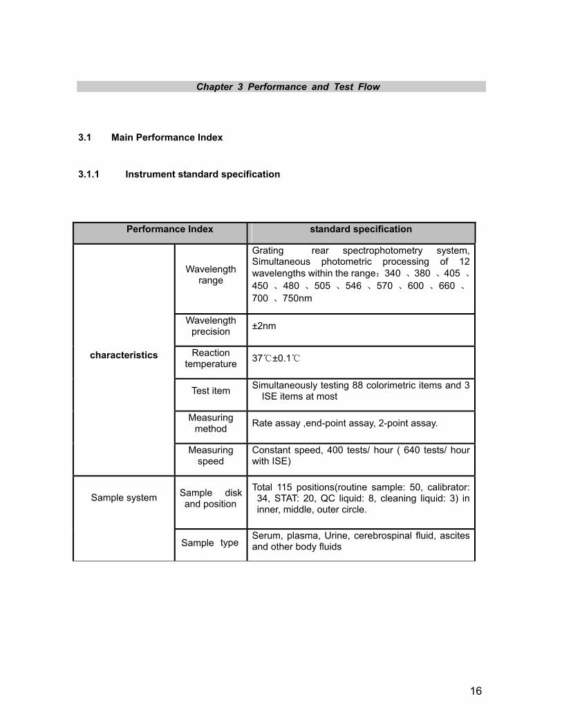
3.1.1 Instrument standard specification
Performance Index standard specification
Wavelength range
Grating rear spectrophotometry system, Simultaneous photometric processing of 12 wavelengths within the range:340 、380 、405 、450 、480 、505 、546 、570 、600 、660 、700 、750nm
Wavelength precision ±2nm
Reaction temperature 37℃±0.1℃
Test item Simultaneously testing 88 colorimetric items and 3 ISE items at most
Measuring method Rate assay ,end-point assay, 2-point assay.
characteristics
Measuring speed
Constant speed, 400 tests/ hour ( 640 tests/ hour with ISE)
and position
Total 115 positions(routine sample: 50, calibrator: 34, STAT: 20, QC liquid: 8, cleaning liquid: 3) in inner, middle, outer circle.
Sample system
Sample type Serum, plasma, Urine, cerebrospinal fluid, ascites and other body fluids
17
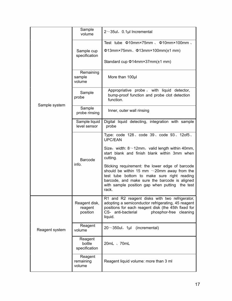
Sample volume 2~35ul,0.1μl Incremental
Sample cup specification
Test tube Φ10mm×75mm 、 Φ10mm×100mm 、
Φ13mm×75mm、Φ13mm×100mm(±1 mm)
Standard cup Φ14mm×37mm(±1 mm)
Remaining sample volume
More than 100μl
Sample probe
Appropriative probe , with liquid detector, bump-proof function and probe clot detection function.
Sample probe rinsing Inner, outer wall rinsing
Sample liquid level sensor
Digital liquid detecting, integration with sample probe
Barcode info.
Type: code 128、code 39、code 93、12of5、UPC/EAN
Size:width: 8~12mm,valid length within 40mm, start blank and finish blank within 3mm when cutting.
Sticking requirement: the lower edge of barcode should be within 15 mm ~20mm away from the test tube bottom to make sure right reading barcode, and make sure the barcode is aligned with sample position gap when putting the test rack.
Reagent disk, reagent position
R1 and R2 reagent disks with two refrigerator, adopting a semiconductor refrigerating, 45 reagent positions for each reagent disk (the 45th fixed for CS- anti-bacterial phosphor-free cleaning liquid.
Reagent volume 20~350ul,1μl (incremental)
Reagent bottle
specification 20mL 、70mL
Reagent system
Reagent remaining volume
Reagent liquid volume: more than 3 ml
Sample system
18
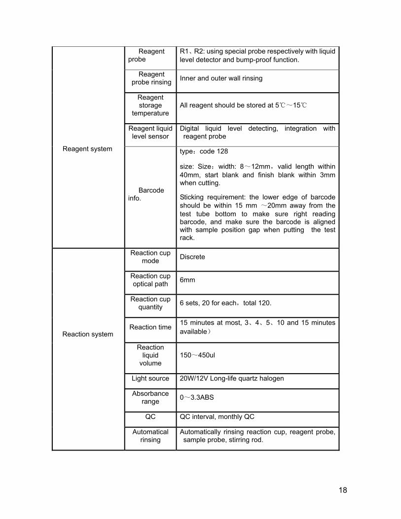
Reagent probe
R1、R2: using special probe respectively with liquid level detector and bump-proof function.
Reagent probe rinsing Inner and outer wall rinsing
Reagent storage
temperature All reagent should be stored at 5℃~15℃
Reagent liquid level sensor
Digital liquid level detecting, integration with reagent probe
Barcode info.
type:code 128
size: Size:width: 8~12mm,valid length within 40mm, start blank and finish blank within 3mm when cutting.
Sticking requirement: the lower edge of barcode should be within 15 mm ~20mm away from the test tube bottom to make sure right reading barcode, and make sure the barcode is aligned with sample position gap when putting the test rack.
Reaction cup mode Discrete
Reaction cup optical path 6mm
Reaction cup quantity 6 sets, 20 for each,total 120.
Reaction time 15 minutes at most, 3、4、5、10 and 15 minutes available)
Reaction liquid
volume 150~450ul
Light source 20W/12V Long-life quartz halogen
Absorbance range 0~3.3ABS
QC QC interval, monthly QC
Reaction system
Automatical rinsing
Automatically rinsing reaction cup, reagent probe, sample probe, stirring rod.
Reagent system

19
Stirring system Separately stirring after adding reagent
interface TCP/IP network interface, standard RS-232 and USB 2.0 interface.
Printer Stylus printer, supporting the user-defined mode for report sheet Data system
Connecting LIS/HIS system
LIS/HIS system available
weight Approximate 300Kg
Dimensions 1060 mm×790 mm×1150mm(length×width×height)
Power(VA) 2000VA Instrument system
Water consumption 25L/h
Power supply 220V/230V,50Hz/60Hz,2000VA
Installation requirement
Using environment
System storage temperature:0℃ ~ 40℃ ,
volatility <±2℃/H;storage humidity:30%RH~
80%RH , non-condensing ; at working, temperature:15℃ ~ 30℃ , volatility<±2℃/H ; at working, relative humidity:35%RH ~
80%RH,non-condensing;not higher than 2000 meters above sea level。
3.1.2 Testing speed
Note:Due to the different specific conditions, sometimes equipment processing capacity will be
lower than 400 tests / hour.
Test conditions Degree of reduced ability to process (estimated)
Retest after sample prediluted 133tests/h(all tests after redilution )
200 tests/h at least(reaction cup、sample probe)
Use avoiding cross contamination function 200~400tests/h (reagent probe)
R1 and R4 items or R2 and R3 items are used simultaneously in testing.
200tests/h at least

figure 3-1 test flow
20
3.2 Test Flow
3.2.1 Typical test flow
13min 3os
Initialrunning(Reesetting)
St art
Rinse reaction cup
4tim
esofm
easuringw
aterblank
Assim
ilatew
ater
Add
sample
Add
reagent1
stir
Add
reagent2
stir
Add
reagent3
stir
Add
reagent4
stir
Testedcom
pletely
Rinse reaction cup
Stop automatically
9s
More then72s 18s 3min plus27s
4 min plus 57s
9min 18s
15min 3min
9s for one additional sample
Total time for testing the 1st sample: 18min
1min plus 21s
21
a. Rotate to above reaction disk
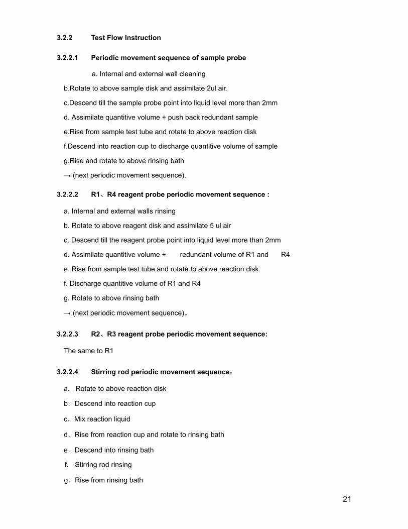
3.2.2 Test Flow Instruction
3.2.2.1 Periodic movement sequence of sample probe
a. Internal and external wall cleaning
b.Rotate to above sample disk and assimilate 2ul air.
c.Descend till the sample probe point into liquid level more than 2mm
d. Assimilate quantitive volume + push back redundant sample
e.Rise from sample test tube and rotate to above reaction disk
f.Descend into reaction cup to discharge quantitive volume of sample
g.Rise and rotate to above rinsing bath
→ (next periodic movement sequence).
3.2.2.2 R1、R4 reagent probe periodic movement sequence :
a. Internal and external walls rinsing
b. Rotate to above reagent disk and assimilate 5 ul air
c. Descend till the reagent probe point into liquid level more than 2mm
d. Assimilate quantitive volume + redundant volume of R1 and R4
e. Rise from sample test tube and rotate to above reaction disk
f. Discharge quantitive volume of R1 and R4
g. Rotate to above rinsing bath
→ (next periodic movement sequence)。
3.2.2.3 R2、R3 reagent probe periodic movement sequence:
The same to R1
3.2.2.4 Stirring rod periodic movement sequence:
b.Descend into reaction cup
c.Mix reaction liquid
d.Rise from reaction cup and rotate to rinsing bath
e.Descend into rinsing bath
f. Stirring rod rinsing
g.Rise from rinsing bath

22
figure 3-2 Position of reaction disk and probe
3.2.2.5 Movement and time sequence of reaction disk
A track includes total 120 reaction cups in reaction disk, and rotates in a fixed way when testing. The reaction cup always rotates and stops 3 times counterclockwise, total 22+37+2=61 (rotation and stop sequence 22-37-2-)patches, in every working period, 9 seconds elapsed. 122 patches are passed in two working periods within 18 seconds.
Reference position
number
Position No. of reaction cuvette.
Rinsing mechanism
Photoelectric
detection
Sop and wipe
Sample probe
Stirring rod
Reagent probe 2.3
Reset point
R1, R4 Probe
60 R1 Pipetting
61 R4 Pipetting
62,R1 stirring po
63,R4 stirring pos
Outer circle figure: No. of reaction;inner circle figure: No. of mechanism position;
Sample position: No. 1 position; reagent 1,4 probes: No.60,61 position; stirring at NO.62,63 position; reagent 2,3 probes: No. 31 position, stirring: No. 33 position; reaction cup rinsing mechanism: No. 101、103、105、107、109、117、11 position.
Reaction cup stops at No. 101 position after reaction disk resetting. The sequence of reaction cup rinsing and sampling:
1→62→3→64→5→66→7→68→ …… →59→120→(9 minutes,60times)
61→2→63→4→65→6→67→8→ …… →119→60(9 minutes,60times)
23
figure 3-3 Reaction cup ri
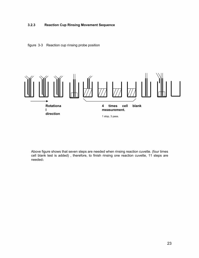
3.2.3 Reaction Cup Rinsing Movement Sequence
nsing probe position
Above figure shows that seven steps are needed when rinsing reaction cuvette. (four times cell blank test is added) , therefore, to finish rinsing one reaction cuvette, 11 steps are needed:
Rotatil
测 4 次杯空白(1 次停止,
次通过)Rotational direction
f
4 times cell blank measurement.
1 stop, 3 pass.
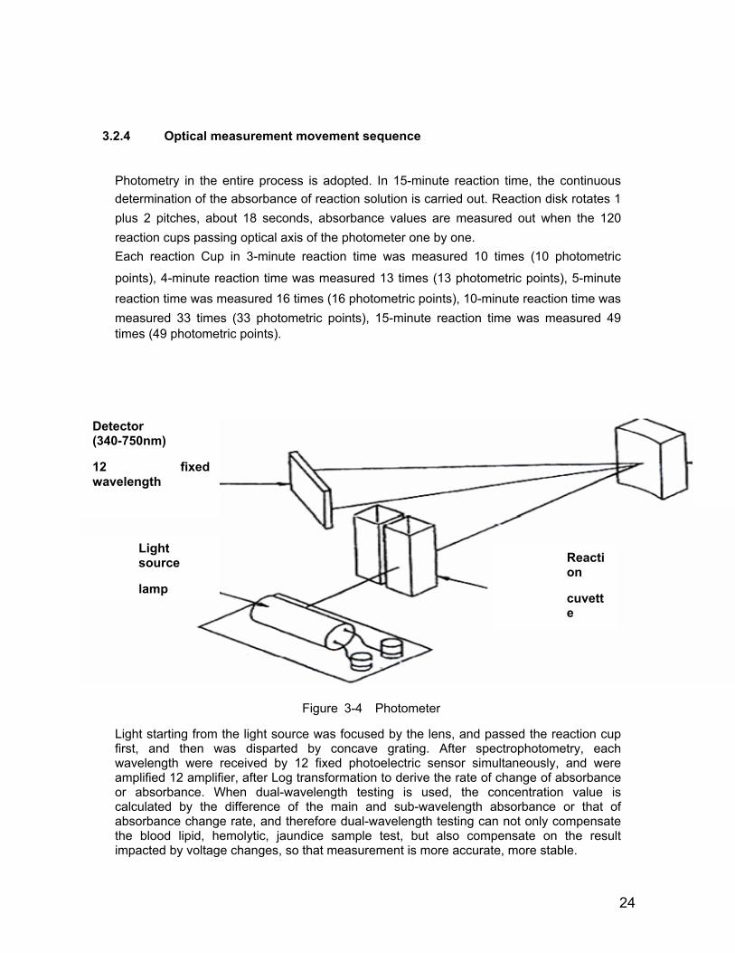
Figure 3-4 Photometer
24
3.2.4 Optical measurement movement sequence
Photometry in the entire process is adopted. In 15-minute reaction time, the continuous determination of the absorbance of reaction solution is carried out. Reaction disk rotates 1 plus 2 pitches, about 18 seconds, absorbance values are measured out when the 120 reaction cups passing optical axis of the photometer one by one. Each reaction Cup in 3-minute reaction time was measured 10 times (10 photometric
points), 4-minute reaction time was measured 13 times (13 photometric points), 5-minute reaction time was measured 16 times (16 photometric points), 10-minute reaction time was measured 33 times (33 photometric points), 15-minute reaction time was measured 49 times (49 photometric points).
3-4 Optical system
Light starting from the light source was focused by the lens, and passed the reaction cup first, and then was disparted by concave grating. After spectrophotometry, each wavelength were received by 12 fixed photoelectric sensor simultaneously, and were amplified 12 amplifier, after Log transformation to derive the rate of change of absorbance or absorbance. When dual-wavelength testing is used, the concentration value is calculated by the difference of the main and sub-wavelength absorbance or that of absorbance change rate, and therefore dual-wavelength testing can not only compensate the blood lipid, hemolytic, jaundice sample test, but also compensate on the result impacted by voltage changes, so that measurement is more accurate, more stable.
Reaction
cuvette
Light source
lamp
Detector (340-750nm)
12 fixed wavelength

25
Chapter 4. Module Introduction
4.3 Sample / reagent probe unit
4.3.1 Function introduction
Sample/reagent probe unit includes sample probe, No. 1 sample probe(R1) and No.2 sample probe (R2), which are called 3-probe component.
Sample probe can realize the assimilation from the sample test tube and sampling into reaction cup. No. 1 sample probe(R1) and No.2 sample probe (R2) can realize the assimilation from the reagent bottle and adding reagent into reaction cup.
In addition, main function of 3-probe component: liquid level detecting and bump-proof in movement process, sample probe block detecting function.
Other subsidiary function includes mechanical limit, power-down self-locking function.
3-probe component working position:
1. sample probe component : rinsing bath→sample disk assimilating position→reaction disk/ISE sampling position;
2. reagent probe component : rinsing bath→reagent disk assimilating position→reaction disk/ISE adding position
Probe drive mechanism plays a key role of reagents and samples adding. The way of probe are only up-down and circular moving, so two step motors are necessary to drive.
4.3.2 Composition and configuration
Figure 4-1 probe components configuration
Reagent 1, reagent 2 and sample probe drive mechanism in addition to different probe turning angles, namely the corner mechanical limit block tablets different, the other structures are identical.
Probe rotating arm Probe rotating gear
belt
Probe rotating step motor
Probe up-down step motor
Probe up-down gear belt
Probe up-down weight block
Probe up-down guide slider
Probe up-down light sensor block tablet
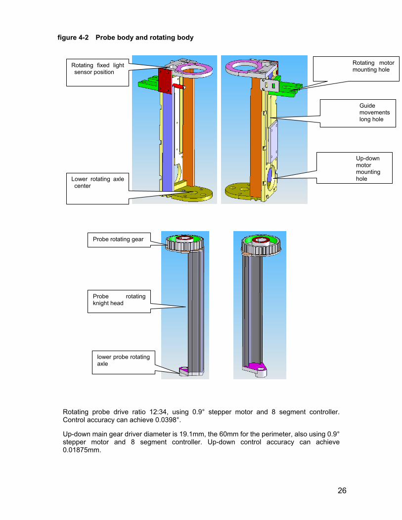
figure 4-2 Probe body and rotating body
26
Rotating probe drive ratio 12:34, using 0.9° stepper motor and 8 segment controller. Control accuracy can achieve 0.0398°.
Up-down main gear driver diameter is 19.1mm, the 60mm for the perimeter, also using 0.9° stepper motor and 8 segment controller. Up-down control accuracy can achieve 0.01875mm.
Probe rotating gear
Probe rotating knight head
lower probe rotating axle
Rotating motor mounting hole
Up-down motor mounting holeLower rotating axle
center
Guide movements long hole
Rotating fixed light sensor position
27
4.4 Rotating mechanism unit
4.4.1 Function Introduction
The main function of rotating mechanism is bearing of the sample warehouse, reagent warehouse and reaction disk, and drive it to rotate, so that sample, reagent carried in reaction cup rotate to the designated location to finish sampling, mixing and other work.
Reagent disk 1, reagent disk 2, the sample disk and reaction disk mechanisms are classified as turntable mechanism. Meeting the requirements of functionality and performance simultaneously, in order to improve the craftwork of product, the four disks are designed as the same frame structure.
4.4.2 Rotating mechanism configuration
1, the sample turntable: The sample storehouse, disk rotating bracket, step motor-driven components
2, reagent turntable: The reagents storehouse, disk rotating bracket, step motor-driven components
3, the reaction disk turntable: reaction plate, the reaction cup, incubation bath, disk rotating bracket, step motor-driven components
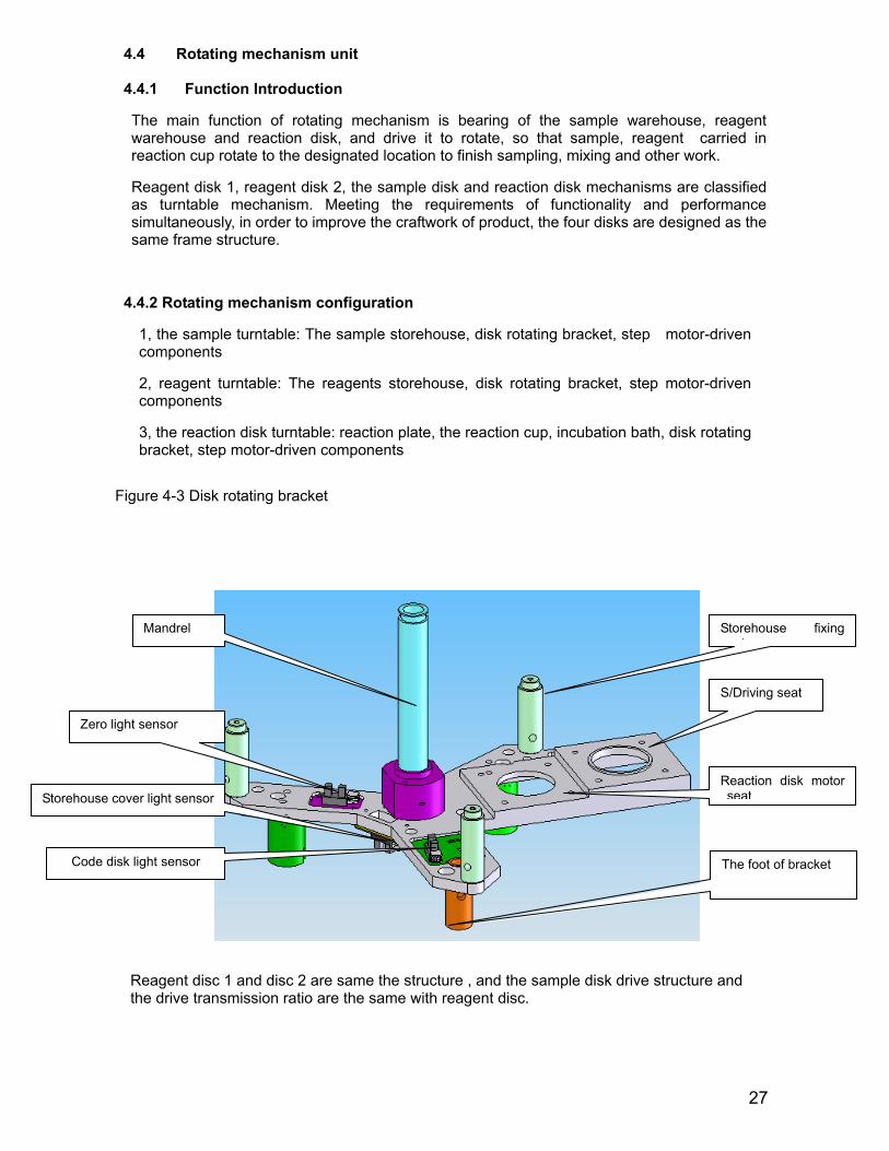
Figure 4-3 Disk rotating bracket
Reagent disc 1 and disc 2 are same the structure , and the sample disk drive structure and the drive transmission ratio are the same with reagent disc.
Storehouse fixing t
S/Driving seat
Reaction disk motor seat
The foot of bracket
Mandrel
Zero light sensor
Storehouse cover light sensor
Code disk light sensor
28
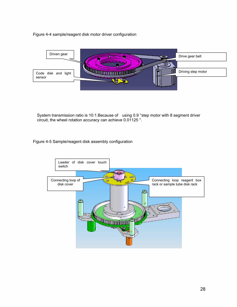
Figure 4-4 sample/reagent disk motor driver configuration
System transmission ratio is 10:1.Because of using 0.9 °step motor with 8 segment driver circuit, the wheel rotation accuracy can achieve 0.01125 °.
Figure 4-5 Sample/reagent disk assembly configuration
Drive gear belt
Driving step motor
Driven gear
Code disk and light sensor
Connecting loop reagent box rack or sample tube disk rack
Leader of disk cover touch switch
Connecting loop of disk cover
29
4.5 Cooling mechanism
4.5.1 Function Introduction
R1 and R2 with two refrigerated reagent disk, adopting semiconductor refrigeration, the
temperature maintains at 6 degrees -10 degrees, 45 reagent positions for each reagent
disk respectively(the 45th fixed position for placing phosphor-free CS-anti-bacterial
cleaning liquid in each disk)
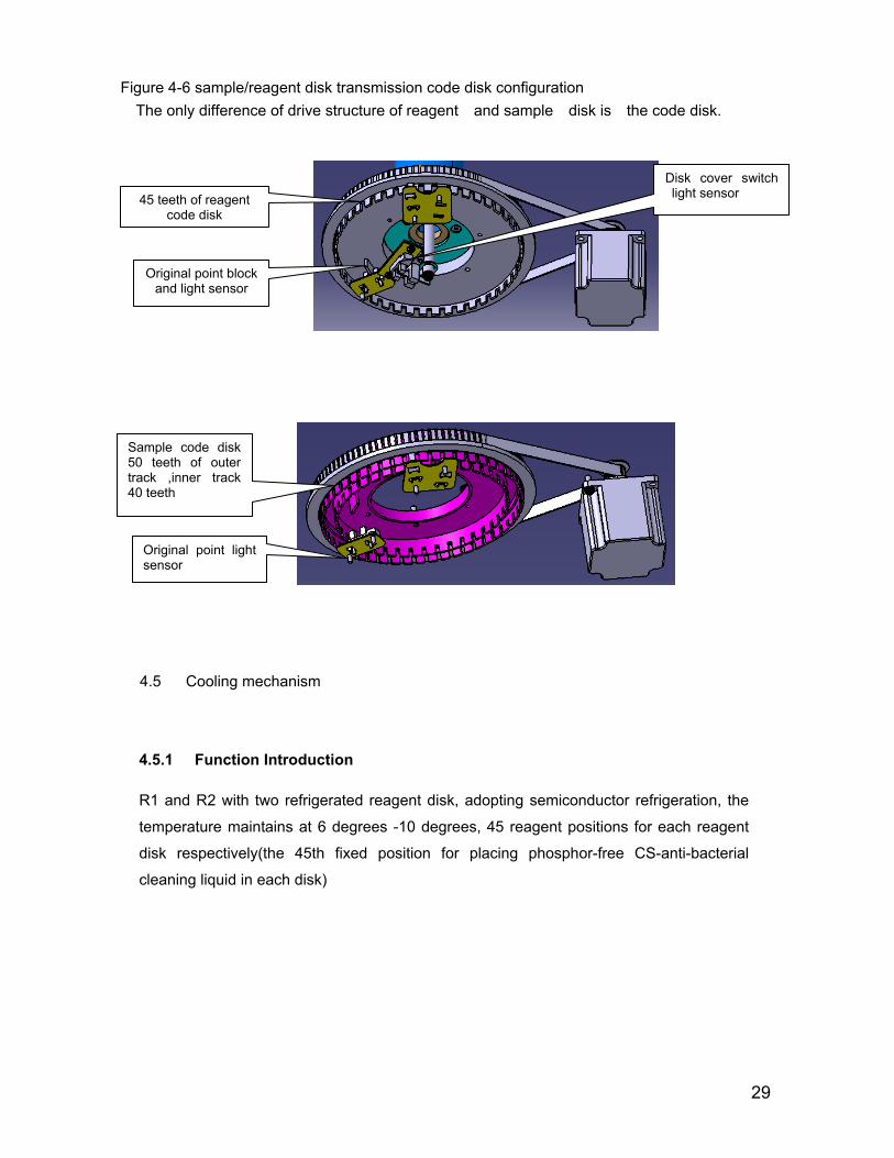
45 teeth of reagent code disk
Sample code disk 50 teeth of outer track ,inner track 40 teeth
Original point block and light sensor
Disk cover switch light sensor
Original point light sensor
Figure 4-6 sample/reagent disk transmission code disk configuration The only difference of drive structure of reagent and sample disk is the code disk.
30
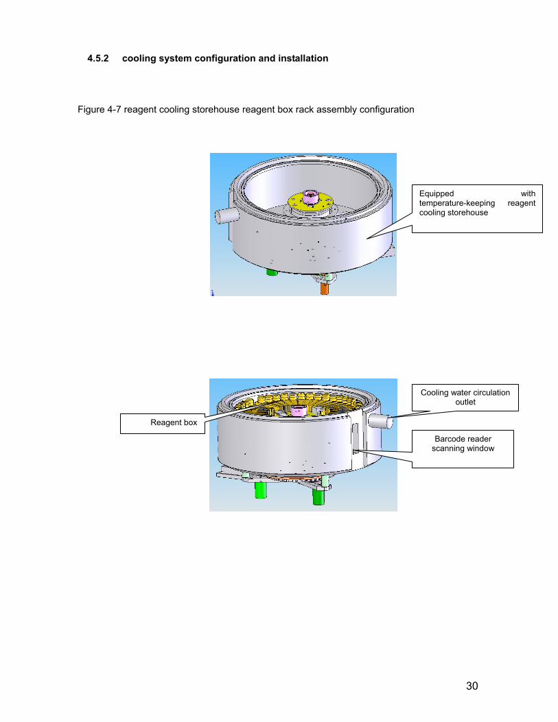
Figure 4-7 reagent cooling storehouse reagent box rack assembly configuration
Cooling water circulation outlet
Barcode reader scanning window
Reagent box
Equipped with temperature-keeping reagent cooling storehouse
4.5.2 cooling system configuration and installation
31
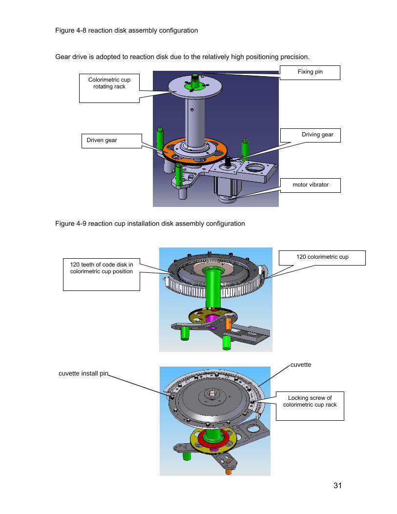
Figure 4-8 reaction disk assembly configuration
Gear drive is adopted to reaction disk due to the relatively high positioning precision.
Figure 4-9 reaction cup installation disk assembly configuration
Driving gear
motor vibrator
Driven gear
Fixing pin Colorimetric cup
rotating rack
120 teeth of code disk in colorimetric cup position
120 colorimetric cup
6 sets of colorimetric
Locking screw of colorimetric cup rack
cuvettecuvette install pin
32
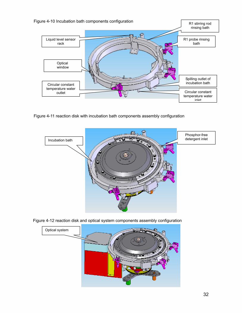
Figure 4-10 Incubation bath components configuration
Figure 4-11 reaction disk with incubation bath components assembly configuration
R1 probe rinsing bath
R1 stirring rod rinsing bath
Spilling outlet of incubation bath
Liquid level sensor rack
Optical window
Circular constant temperature water
outlet Circular constant temperature water
inlet
Figure 4-12 reaction disk and optical system components assembly configuration
Phosphor-free detergent inlet Incubation bath
Optical system

33
4.6 Stirring unit
4-6-1 function introduction Stir and mix reagent after adding it
Reagent 1, reagent 2 agencies are identical in addition to the mixing angle of rotation,
namely the code disk is different.
4-6-2 Stirring components configuration and installation
Figure 4-13 Stirring components configuration
Rotating mechanism of stirring and rotating arm adopts the direct drive way of
step motor output axle, using 8 segment drive circuit of 0.9 ° motor, and the control
accuracy can achieve 0.1125 °. The largest angle is limited by the open angle of
rotatation code disk mechanical limit. And positioning is determined separately by
the left and right light sensors.
Stirring mechanism up-down motor
Mechanism rotation mechanical limit
Rotation code disk and light sensor
Stirring mechanism up-down slider
Figure 4-14 stirring up-down driver configuration
Curve axle and curve handle drive is adopted by stirring up-down mechanism .
Stirring mechanism up-down motor
Stirring mechanism up-down light
sensor
Up-down slider axle
34
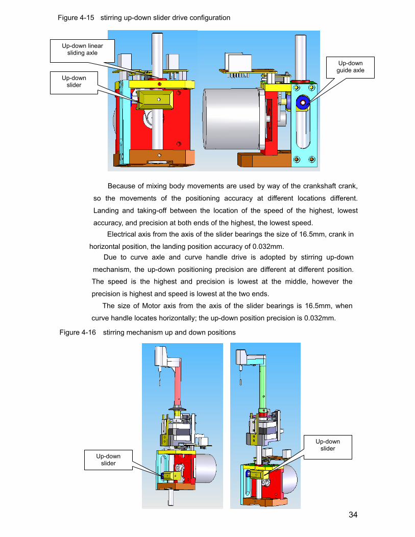
Figure 4-15 stirring up-down slider drive configuration
Because of mixing body movements are used by way of the crankshaft crank,
so the movements of the positioning accuracy at different locations different.
Landing and taking-off between the location of the speed of the highest, lowest
accuracy, and precision at both ends of the highest, the lowest speed.
Electrical axis from the axis of the slider bearings the size of 16.5mm, crank in
horizontal position, the landing position accuracy of 0.032mm. Due to curve axle and curve handle drive is adopted by stirring up-down
mechanism, the up-down positioning precision are different at different position.
Up-down linear sliding axle
Up-down slider
Up-down guide axle
The speed is the highest and precision is lowest at the middle, however the
precision is highest and speed is lowest at the two ends.
The size of Motor axis from the axis of the slider bearings is 16.5mm, when
curve handle locates horizontally; the up-down position precision is 0.032mm.
Figure 4-16 stirring mechanism up and down positions
Up-down slider
Up-down slider
35
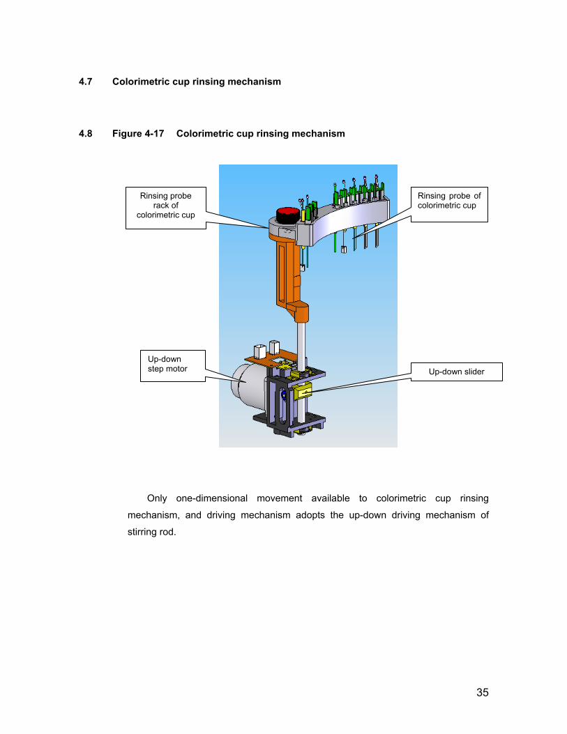
4.7 Colorimetric cup rinsing mechanism
4.8 Figure 4-17 Colorimetric cup rinsing mechanism
Only one-dimensional movement available to colorimetric cup rinsing
mechanism, and driving mechanism adopts the up-down driving mechanism of
stirring rod.
Up-down step motor Up-down slider
Rinsing probe of colorimetric cup
Rinsing probe rack of
colorimetric cup
36
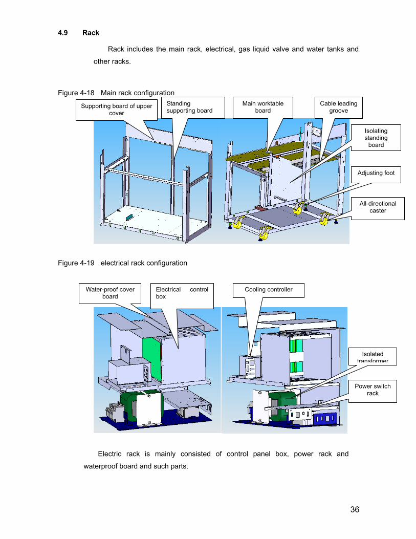
4.9 Rack
Rack includes the main rack, electrical, gas liquid valve and water tanks and
other racks.
Figure 4-18 Main rack configuration
Figure 4-19 electrical rack configuration
Supporting board of upper cover
Standing supporting board
Main worktable board
Cable leading groove
Adjusting foot
All-directional caster
Isolating standing
board
Water-proof cover board
Electrical control box
Cooling controller
Isolated transformer
Power switch rack
Electric rack is mainly consisted of control panel box, power rack and
waterproof board and such parts.
37
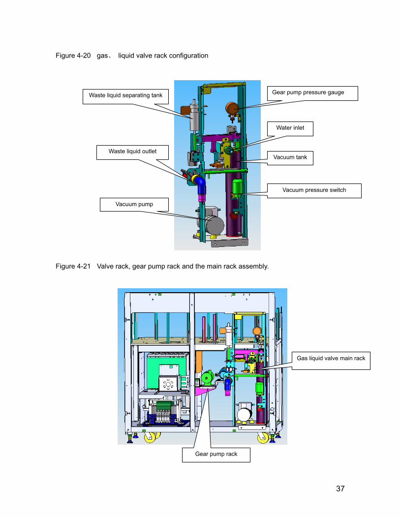
Figure 4-20 gas、 liquid valve rack configuration
Figure 4-21 Valve rack, gear pump rack and the main rack assembly.
Gear pump pressure gauge
Water inlet
Vacuum tank
Vacuum pressure switch
Vacuum pump
Waste liquid separating tank
Waste liquid outlet
Gas liquid valve main rack
Gear pump rack

38
4.10 Optical system
CS-400 adopts advanced flat field grating photometer. Concave holographic grating photometer is today's domestic and foreign advanced optical system with simple structure, high optical efficiency, and signal to noise ratio and measurement speed of machine have greatly been improved, compact photometer dimension, stable performance, long life, and such highlighting advantage, achieving the requirements such as multi-wavelength, multi-item simultaneously testing at high speed, multi-wavelength (12) simultaneously collecting signals, a relatively large aperture, good imaging quality and post-spectrophotometry.
Figure 4-23 Optical assembly
Diaphragm
Flat field grating
Water-cooled light source
Bunching lens set
Photoelectirc cable array
Log applifier
figure 4-22 Water-in tank unit configuration
Heating water tank
Vacuum exhausting tank
Pressure gauge
Magnetic pump

39
10. The vacuum degree for vacuum pum
Chapter 5. Instrument liquid and Gas Line.
5.1 Main function of liquid line
The CS400 liquid line system can be divided into five parts: water inlet tank, refrigeration, 37 degrees centigrade temperature, colorimetric cup cleaning, the inner and outer arms and stirring rod cleaning.
1. CS400 liquid line system includes sampling subsystem and cleaning subsystem.
2. Sampling subsystem uses three probes plus two stirring rods and three injectors. The sampling injector uses 100uL, and the two reagent injectors use 500uL.
3. The inner and outer wall cleaning of three probes and two stirring rods uses barotropic driving.
4. Cleaning bath: five cleaning bathes plus waste liquor in the reagent storehouse, together with the flooding waste liquor in the reaction disk are seven kinds of routine waste liquor.
5. The reaction cup cleaning uses the way named 7-stop 11-step.
6. Water supply: uses the special outboard water-supply equipment and the special water-supplying machine.
7. Waste liquor: use plastic hollow main pipe whose inside diameter is 20 to 30 mm, and the wall thickness is 3 to 5 mm. The installation of the main waste liquor pipe is height limited, and it requires the height is helpful to the waste liquor entering the low concentration liquid buffer vessel by its self-weight. As to the high concentration waste liquid, it is providing liquid level sensor interface and outboard high concentration waste liquid barrel.
8. Source of power: the power of cleaning comes from the magnetic pump..
9. The cleaning of reaction cup should use two kinds of detergent..
p assimilating is between -28k and -35kPa.
11. The inner and outer wall cleaning of three probes uses independent solenoid valves while the two stirring rods use one solenoid valve together.

40
5.2 Liquid Line Principle
Figure 5-1 CS-400 liquid line sketch map

41
Figure 5-2 liquid line of water inlet tank
1, when the low water level float detects out the signal, open the inlet valves
SV8, and water tank begins to be infused water until the high water level float
detects out signal, then turn off SV8 to stop the water. Influent flow is as follows:
2, when the low water level float did not detect out signal, the water tank heater began to work, and temperature control started. Magnetic pump began to work simultaneously. 3, Output water pressure of water tank is controlled by the magnetic pump and fixed damper regulator. Magnetic pump head is 8 / 11 m. Control water pressure is around 0.8kgf/cm2.
4, The outlet of tank water leads directly to the cleaning and incubation bath; the other output water through gear pump supercharger to the pressure 1kgf/cm2 to 3 line probe mechanisms to rinse inner wall and pipeline, with exhausting device of probe liquid line. 5, SV13 valve remains closed status so as not to affect water pressure during the normal use of instrument. Only in the implementation of the maintenance of water tanks, open SV13 valve, at the same time, time switch of SV8 inlet valve to empty impurities in a water tank. 6, when abnormality occurs to the high and low water level floats, possibly water tank remains the status of inputting water. When the water tank is full of water, SV8 not shut down, tank outflow water spills out from the overflow pipe into the waste liquid barrel through waste liquid pipe.
Alarm of low water level check
influent water Alarm of high water level check
Stop influent water
42
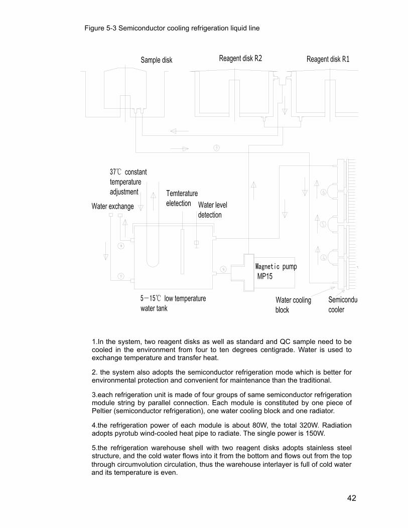
1.In the system, two reagent disks as well as standard and QC sample need to be cooled in the environment from four to ten degrees centigrade. Water is used to exchange temperature and transfer heat.
2. the system also adopts the semiconductor refrigeration mode which is better for environmental protection and convenient for maintenance than the traditional.
3.each refrigeration unit is made of four groups of same semiconductor refrigeration module string by parallel connection. Each module is constituted by one piece of Peltier (semiconductor refrigeration), one water cooling block and one radiator.
4.the refrigeration power of each module is about 80W, the total 320W. Radiation adopts pyrotub wind-cooled heat pipe to radiate. The single power is 150W.
5.the refrigeration warehouse shell with two reagent disks adopts stainless steel structure, and the cold water flows into it from the bottom and flows out from the top
Figure 5-3 Semiconductor cooling refrigeration liquid line
through circumvolution circulation, thus the warehouse interlayer is full of cold water and its temperature is even.

43
6.the refrigeration volume of sample disk is small and the refrigeration area is formed by aluminum cylinder, so the aim of refrigeration can be achieved by circulating stainless steel tube. The whole circulation process is finished by magnetic pump with a head 2.7m.
7. sluice water tank can check temperature and water level. The scope of temperature is from 5 to 15 degrees centigrade above zero.
8.the refrigeration water tank is complete closed.
When adding water, it should be added from the inlet tube at the bottom by filler. About 1.5 litter is added into water tank or flowing-out water from the top of water tank observed (the two water-changing nozzle should be above the water tank, water-changing tube is mainly used to exhaust). Here, turn on the main power supply and the refrigeration system starts to work. Then the water level will drop, water should be added continuously until the exhausting tube reflows out water. When working stably, there is no change with the water level of exhausting tube, and the two water-changing tube plugs should be installed. If there is no leakage, the system water changing has been finished.
When spouting the water, please turn off the main power supply, pull out the two water-changing tube plugs and contain water with container. The total water volume is approximately four litters.
Use the fresh water to do the refrigeration circulation, check it annually.

44
Figure 5-4 constant temperature system liquid line
This system offers precise constant 37 degrees water to the incubation bath of reaction disk,
and cools the high temperature light source simultaneously. This system consists of magnetic
pumps, inlet valves, release valves, liquid level detector and temperature controller which
consists of the heater temperature
1, Open the inlet valve SV10 and turn off outlet valves SV16 to infuse water into
incubation bath, simultaneously with reagent R1 and R2 probes adding
phosphor-free anti-bacterial rinsing liquid to the incubation bath, liquid level detector
determining whether to stop water. 2, Turn off outlet valve and inlet valve, and start the water circulation magnetic
pump and temperature controller. In order to improve the adjusting performance of
the PID temperature controller in high temperature environment, the system is
added the cooling device through the water tank to get a small amount of
temperature cooled. 3, Turn off magnetic pump and temperature controller, open the drain valve SV16,
time to turn off the drain valve when the incubation bath is draining.

45
1, Opening the valves SV1 and SV41 simultaneously can get the inner wall of sample probe rinsed; open valve SV2 or SV3 to carry out reagent probe R1 or R2 internal wall cleaning. Probe position should be at the top of the corresponding cleaning trough when cleaning so that waste liquid can get out of the instrument.
2、Open the valve SV4、SV5、SV9 or SV6 to rinse the external walls of sample, reagent R1, R2 or 2 stirring rods. Each stirring rod has one corresponding valve respectively. Fixing pressure adjusting piston is adopted to every external wall rinsing pipeline to avoid rinsing water spilling out of rinsing bath.
3, valve SV1 pressure testing and the valve SV41 constitutes series structure, not only completing the sample probe cleaning of the inner wall, but also completing the block detection of probe, which does not affect the accuracy of assimilating and discharging liquid volume of a small amount of sample.
4. The block detection must be implemented when probe is cleaned. Turn off valve SV1 after the cleaning, Detect pressure, and probe is completely blocked or partially blocked if the pressure value change is the same or smaller than the range value. And previous added sample should be deserted and alarm is issued. Turn off SV1 and SV41 when probe assimilates and discharges sample.
Figure 5-5 probe internal and external walls rinsing and sample probe block check liquid line.
46
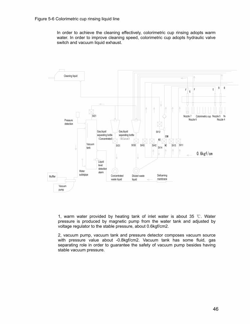
Figure 5-6 Colorimetric cup rinsing liquid line
In order to achieve the cleaning effectively, colorimetric cup rinsing adopts warm water. In order to improve cleaning speed, colorimetric cup adopts hydraulic valve switch and vacuum liquid exhaust.
1, warm water provided by heating tank of inlet water is about 35 ℃. Water pressure is produced by magnetic pump from the water tank and adjusted by voltage regulator to the stable pressure, about 0.6kgf/cm2.
2, vacuum pump, vacuum tank and pressure detector composes vacuum source with pressure value about -0.8kgf/cm2. Vacuum tank has some fluid, gas separating role in order to guarantee the safety of vacuum pump besides having stable vacuum pressure.
47
3, There is a device on the vacuum tank to eliminate air bubbles with liquid, gas separating bottle.
4, vacuum liquid discharging, having concentrated and diluted liquid passages, consists of the valves SV21, SV30, SV31 and concentrated, diluted liquid separating bottles. Concentrated liquid means reaction liquid, including relatively concentrated sample and reagent of patients, requiring separate collection.
5, when the colorimetric cup cleaning mechanism descends, turn off valves SV30 and SV31 first, and then open the valve SV21. It tarts assimilating sample under the vacuum pressure, and the liquid of colorimetric cup will be discharged after a short period of time when the rinsing mechanism arrives at the bottom of Colorimetric Cup.
6, cleaning mechanism begins to add cleaning solution and ionized water, turn off valve SV21 after the addition is completed, and then open valves SV30 and SV31. At this time, the waste liquid discharged into isolating bottle outflows by its gravity.
7, cleaning liquid and ionized water adding is completed by the five valves SV42, SV43, SV14, SV15 and SV11 which are timed. Because the vacuum liquid discharging begins to work simultaneously when adding liquid to discharge redundant liquid, the liquid will not spill outside colorimetric cup. 8, SV12 and SV14 valves are responsible for adding cleaning liquid. Before adding or after the previous adding, open the valve SV12, but SV14 valve is at COM and NO conduction status (power off status). Because there is a one-way valve in the 3-way top pipeline, cleaning fluid flows into the middle pipeline of the SV12 and SV14 valves, and time valve SV12, cleaning liquid will remain in pipeline. Open SV14 valve when adding, cleaning liquid will be added into colorimetric cup through single way valve under the pressure. About 70ul cleaning liquid is consumed every time.
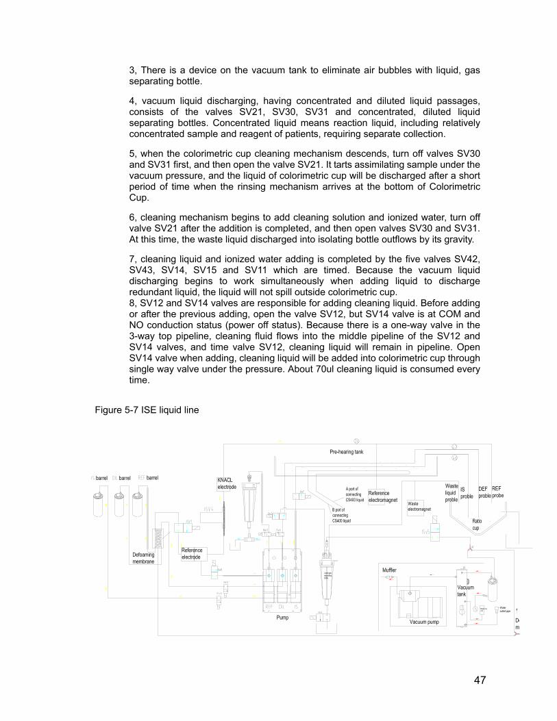
Figure 5-7 ISE liquid line
48
Chapter 6 Instrument Hardware Circuit
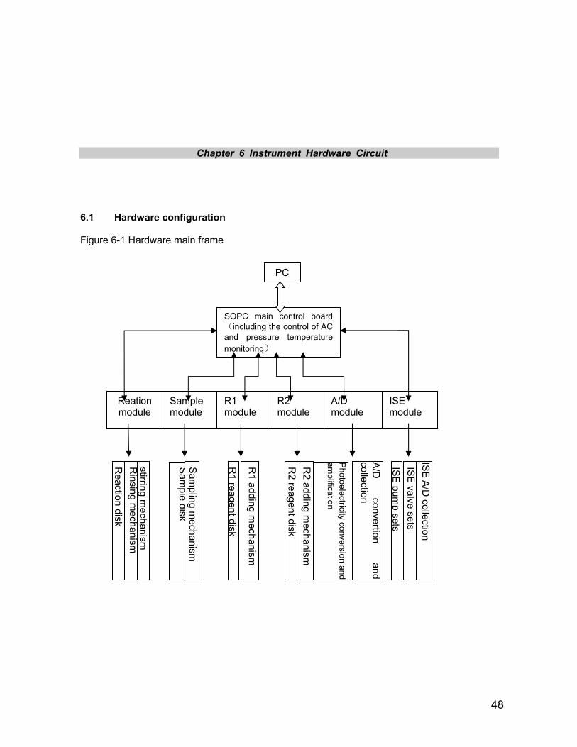
6.1 Hardware configuration
Figure 6-1 Hardware main frame
PC
SOPC main control board(including the control of AC and pressure temperature monitoring)
Sample module
R1 module
R2 module
A/D module
ISE module
Reation module
Reaction disk
Rinsing m
echanism
stirring mechanism
Sam
ple disk S
ampling m
echanism
R1
reagent disk
R1 adding m
echanism
R2 reagent disk
R2 adding m
echanism
Photoelectricity conversion
andam
plification
A/D
convertion and
collection
ISE
pump sets
ISE
valve sets IS
E A/D
collection
49
6.2 Security Note:
At working, touching hardware panel with hand or any other objects is forbidden.
In order to dismount panels, operation is only allowed when cut off power (220V, AC).
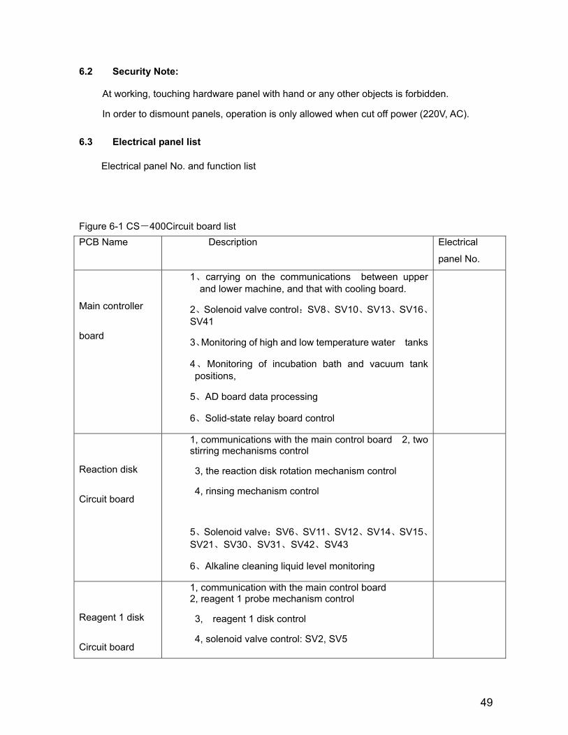
6.3 Electrical panel list
Electrical panel No. and function list
Figure 6-1 CS-400Circuit board list PCB Name Description Electrical
panel No.
Main controller
board
1、carrying on the communications between upper and lower machine, and that with cooling board.
2、Solenoid valve control:SV8、SV10、SV13、SV16、SV41
3、Monitoring of high and low temperature water tanks
4、Monitoring of incubation bath and vacuum tank positions,
5、AD board data processing
6、Solid-state relay board control
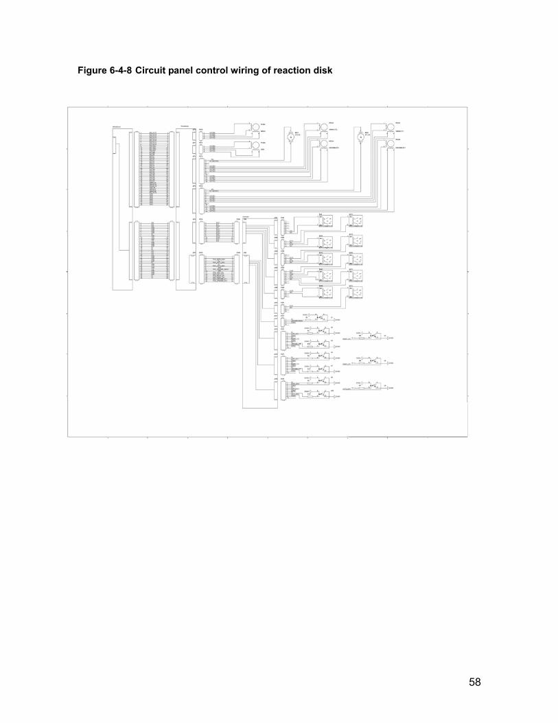
Reaction disk
Circuit board
1, communications with the main control board 2, two stirring mechanisms control
3, the reaction disk rotation mechanism control
4, rinsing mechanism control
5、Solenoid valve:SV6、SV11、SV12、SV14、SV15、SV21、SV30、SV31、SV42、SV43
6、Alkaline cleaning liquid level monitoring
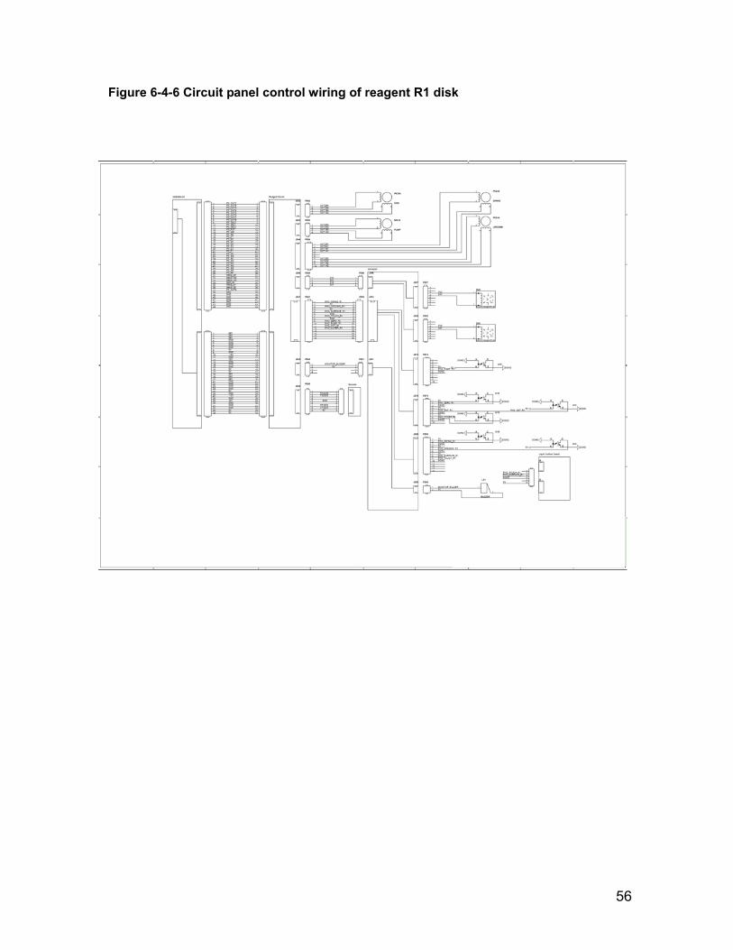
Reagent 1 disk
Circuit board
1, communication with the main control board 2, reagent 1 probe mechanism control
3, reagent 1 disk control
4, solenoid valve control: SV2, SV5

50
5, buzzer control
Reagent 2 disk
Circuit board
1, communication with the main control board
2, reagent 2 probe mechanism control
3, reagent 2 disk control
4, solenoid valve control: SV3, SV9
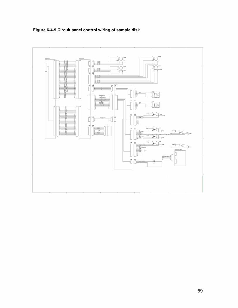
Sample disk
Circuit board
1, communication with the main control board
2, sample probe mechanism control
3, sample disk control
4, solenoid valve control: SV3, SV9
5, the sample disk rotating lamp control
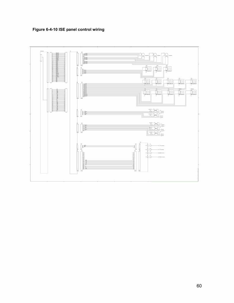
ISE
Circuit board
1, communication with the main control board
2, ISE pump motor control (internal standard, dilution, reference)
3, solenoid control: MAGNET1, MAGNET2
4, solenoid valve control: ISV1, ISV2, ISV3, ISV4, ISV5, ISV6, ISV7, ISV8, ISV11, ISV12, ISV13
5, ISE preamp board data collection
Solid relay board
1,200 W Heater Control
2,450 W Heater Control
3, gear pump control
4, vacuum pump control
5, magnetic pump control
6, water circulation pump
7, halogen control
AD board 12 AD-wavelength data collection
Cooling board 1, semiconductor refrigeration control and temperature display
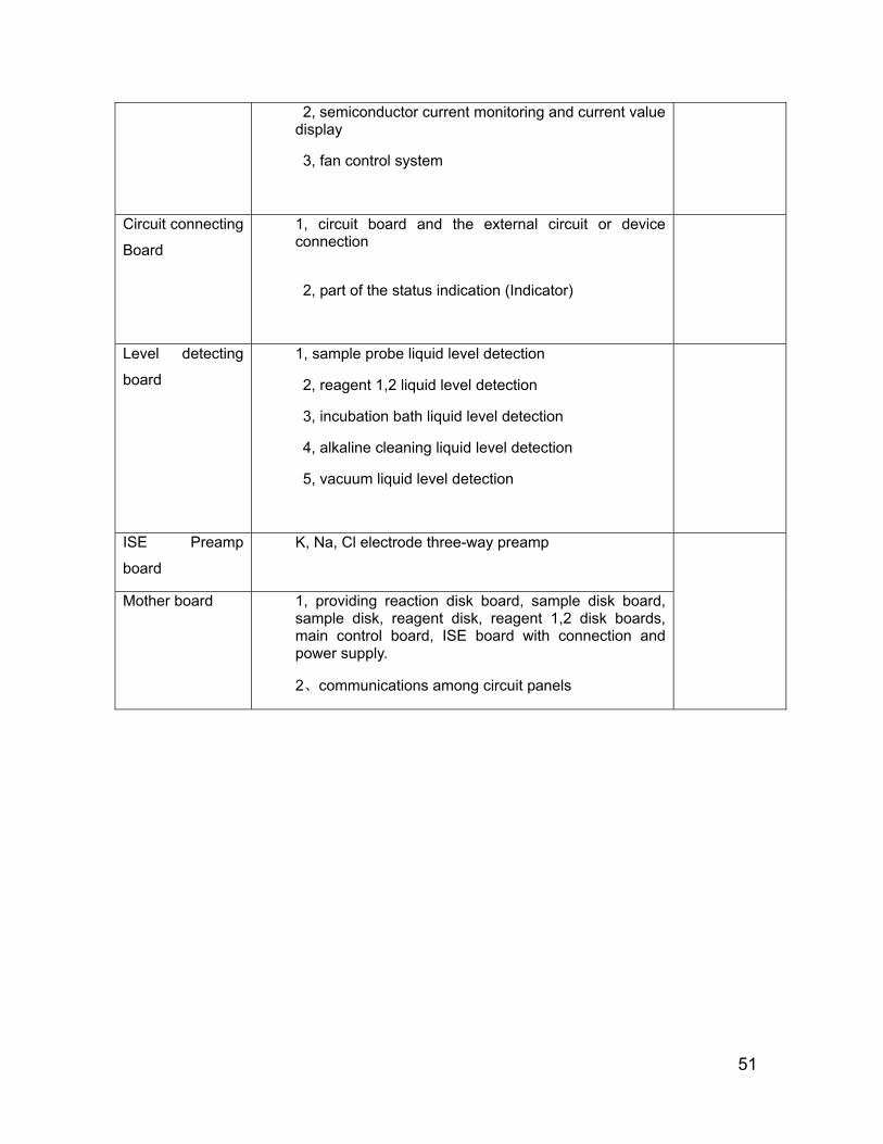
51
2, semiconductor current monitoring and current value display
3, fan control system
Circuit connecting
Board
1, circuit board and the external circuit or device connection
2, part of the status indication (Indicator)
Level detecting
board
1, sample probe liquid level detection
2, reagent 1,2 liquid level detection
3, incubation bath liquid level detection
4, alkaline cleaning liquid level detection
5, vacuum liquid level detection
ISE Preamp
board
K, Na, Cl electrode three-way preamp
Mother board 1, providing reaction disk board, sample disk board, sample disk, reagent disk, reagent 1,2 disk boards, main control board, ISE board with connection and power supply.
2、communications among circuit panels

52
Figure 6-4-1 Control wiring of communication system
6.4 Instrument electrical principle wiring

53
Figure 6-4-2 Power switch wiring
Figure 6-4-3 Cooling board wiring

54
Figure 6-4-4 Main control board wiring
55
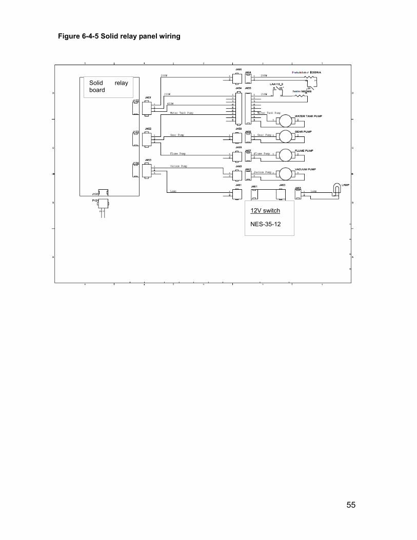
Figure 6-4-5 Solid relay panel wiring
Solid relay board
12V switch
NES-35-12
56
Figure 6-4-6 Circuit panel control wiring of reagent R1 disk

57
Figure 6-4-7 Circuit panel control wiring of reagent R2 disk
58
Figure 6-4-8 Circuit panel control wiring of reaction disk
59
Figure 6-4-9 Circuit panel control wiring of sample disk
60
Figure 6-4-10 ISE panel control wiring
61
6.6 Circuit function
6.6.1 Control configuration CS-400 auto-chemistry analyzer structure consists of analysis part (host), operation part (computer) and the result output part (printer).
Analysis part (host) mainly consists of the temperature control system, the reaction system (including the ISE module), optical detection system, sample and reagent processing system, mixing system, liquid line system and the reaction cup cleansing mechanism.
Overall function of instrument control structure hardware system:
Achieve serial communication with the PC and the completion of command, response and data transceipt;
control data acquisition of optical system;
control the movement and status signal collection of the movement implementation mechanism;
control temperature control system as well as temperature control signal collection;
control ISE electrode data collection;
Control the cooling system.
6.6.2 Main control board function Main function of main control board :
communicate through the serial port with the PC to realize transmission of data, instruction and warning information
communicate through the motherboard with the reaction disk board, the sample disk board, reagent 1 disk board , reagent 2 disk board, ISE board, cooling board, AD board to transmit data and instruction;
monitoring water tank water level and temperature
control water tank temperature
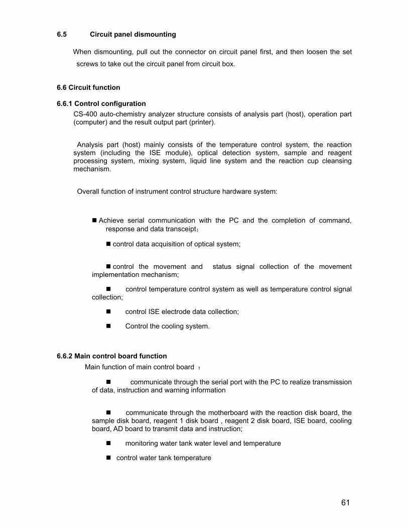
6.5 Circuit panel dismounting
When dismounting, pull out the connector on circuit panel first, and then loosen the set
screws to take out the circuit panel from circuit box.
62
6.6.3 Reaction disk/ sample disk / reagent 1 disk / reagent 2 disk/ ISE board function The main function of circuit boards of three disks are to receive the main control
board's instruction to complete the reaction disk, the sample disk, reagent 1 disk, reagent 2 disk, ISE circuit board work, the specific functions as follows:
Each CPU communicates with the main control board to receive instruction;
Each CPU outputs control order of each executive unit;
to receive the sensor signals and other status of implementation unit;
sent to the main control board If alarm occurs,
6.6.4 AD collecting panel function AD collecting consists of two parts: AD data preamp board and AD data collecting board
1、AD data preamp board:
Preamp board circuit realizes the photoelectric conversion function of discrete photodiode array whose 12 pixels convert the multiwavelength homochromous light signal after transmitting through reaction cup into electric signal, converted by preamp circuit and sending the converted voltage signal to AD collecting board to be processed.
2、AD data collecting board:
AD data collecting board circuit realizes signal adjustment of photoelectric signal output by preamp board and AD collecting function. Photodiode array whose 12 pixels convert the multiwavelength homochromous light signal after transmitting through reaction cup into electric signal, and the 12 photoelectric colorimetric signal output by photoelectric check board is filtrated and amplified by AD collecting board, sent to the input terminal of AD convertor by multi-choosing switch, and at the same time, receive the control signal of main control board to sample one by one from the processed 12 photoelectric signals, and send the AD value of reflecting light intensity to the main control board to process. Besides, AD data collecting board is responsible for the power supply of preamp board.
6.6.5 Cooling board function Cooling system consists of three parts: semiconductor cooling model, radiator, and fan.
The main function of cooling board is to control semiconductor refrigeration module, keeping the water of cold water tank at 6 degrees -10 degrees, to meet the needs of reagent refrigerating warehouse refrigeration function, maintaining the temperature of reagent refrigerated storehouse at the regulated range.
Main function:
control module semiconductor refrigeration
control cooling system fan

63
6.6.6 Power supply system
List of power supply used by circuit panel:
NET-50B ±12V
Series NE series small-size switching power supply
type NET-50B
Output voltage DC 5V,0.6-5A;12V,0.2-2.5A;-12V,0.1-0.7A Output wattage 50W
Output set 3sets
Temperature range
-20~+60℃
Input voltage 85-264VAC/120-370VDC
size 129*98*38mm
Warranty period 2years manufacturing location
Guangzhou
NES-15-12 12V
Series NE series small-size switching power supply
type NES-15-12
Output voltage DC 12V,0-1.3A
Output wattage 15W
Output set 1set
Temperature range -20~+60℃
Input voltage 85-264VAC(120-370VDC)
size 79*51*28mm
Warranty period
2 years
manufacturing location
Guangzhou
64
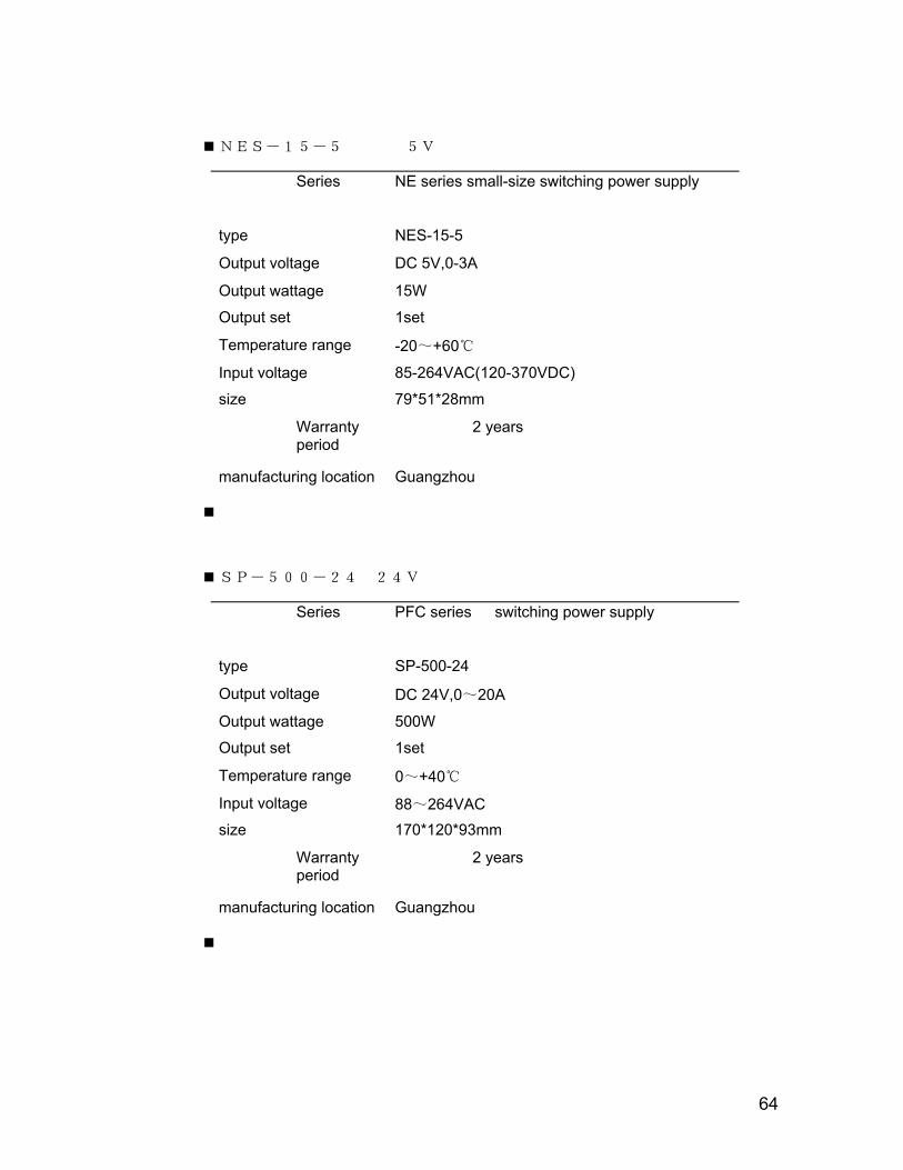
NES-15-5 5V
Series NE series small-size switching power supply
type NES-15-5
Output voltage DC 5V,0-3A
Output wattage 15W
Output set 1set
Temperature range -20~+60℃
Input voltage 85-264VAC(120-370VDC)
size 79*51*28mm
Warranty period
2 years
manufacturing location
Guangzhou
SP-500-24 24V
Series PFC series switching power supply
type SP-500-24
Output voltage DC 24V,0~20A
Output wattage 500W
Output set 1set
Temperature range 0~+40℃
Input voltage 88~264VAC size 170*120*93mm
Warranty period
2 years
manufacturing location
Guangzhou

65
NES-35-12 12V
Series NE series small-size switching power supply
type NES-35-12
Output voltage DC 12V,0-3A
Output wattage 35W
Output set 1set
Temperature range -20~+60℃
Input voltage 85-264VAC(120-370VDC)
size 99*97*36mm
Warranty period
2 years
manufacturing location
Guangzhou

66
Chapter 7 Maintenance and Overhaul
In order to ensure reliable system performance, excellent working status and span, please conduct system operation and regular maintenance strictly in accordance with the requirements in the repair manual. Learning maintenance and overhaul of this chapter is also very important and in-depth study will enable the instrument to achieve the best running status and exert the best performance.
Warning:
Do not carry out maintenance this chapter doesn’t mention. Otherwise, it could lead to system damage and personal injury. Do not touch any other parts except user self-operation and maintenance which are clear recorded. Unauthorized repair of the system may lead to system damage and personal injury, and commitment term of the repair contract is no longer valid. Upon completion of maintenance work, make sure the system is working normally. Do not splash water, reagent and other liquid onto the system's mechanical or electrical parts.
Biological contamination danger :
In the process of maintenance work, be sure to wear gloves, put on work clothes to prevent them from being infected and, if necessary, wear protective glasses.
7.1Maintenace preparation Tools, intensified cleaning liquid and alcohol maybe used in the process of working.
7.1.1 Tools 1. One set of hexagon wrench 2. Cruciform Screwdriver (large, medium and small)
3. Injection needle hose 4. Small tweezers
5. Clean gauze
7.1.2 Intensified cleaning liquid1. Acid cleaning agent, 0.1mol / L hydrochloric acid
2. Alkaline cleaning agent, 0.5% (V / V) sodium hypochlorite
Warning:Intensified acidic and alkaline cleaning liquid mixed generate poisonous gas. Do not mix the intensified acidic and intensified alkaline cleaning liquid. Caution:Following cleaning liquid designated by Dirui Co., Ltd.:Intensified acidic cleaning liquid: 0.1mol / l hydrochloric acid; Intensified alkaline cleaning liquid: 0.5% (V / V) sodium hypochlorite. Please use the intensified cleaning liquid designated by Dirui. If outside of designated types of intensified cleaning liquid are used, it may not be able to receive appropriate the results of the analysis. Dirui recommends the use of alternating acidic and alkaline cleaning liquid, for example, use intensified acidic cleaning fluid after power on, then use of intensified alkaline cleaning liquid next time after power on.

67
3. To observe whether the
2 open the front door and it
1, Make sure that Power of analysis part has been switched off.
is shown as Figure 6-1
If with ISE system, the left are the three ISE unit injection pumps, the middle are injection pumps of sample, reagent 2, reagent 1 respectively.
Figure 6-1
injection pump is leaking,
If so, check the leakage causes, and check the pipeline and connector timely.
7.2.2 Check/rinse sample, reagent probe
1、In online status, click “Instrument resetting” in “Maintenance”, and instrument executes resetting.
2、When cleaning ample and reagent probes, carefully observe whether the outflow of sample probe internal wall is continuous, whether the direction of flow is consistent with the sample probe and the outflow of external wall is continuous, , and whether water volume is normal.
If not normal, clean sample probe
If still not normal, check the corresponding liquid line channel; check whether water supply of water tank and water pressure is normal.
7.2.3 Rinsing stirring rod
1、In online status, click “Instrument resetting” in “Maintenance”, and instrument executes resetting.
7.2 Daily maintenance item
7.2.1 Check injection pump
The purpose of checking the injection pump is check whether the leakage exists.
2, when cleaning, carefully observe whether the stirring rod works normally, If not normal, check the corresponding liquid line channel, check whether water supply of water tank and water pressure is normal.
68
7.2.4 Rinse rinsing mechanism
1、In online status, click “Instrument resetting” in “Maintenance”, and instrument executes resetting.
2、When rinsing, carefully observe rinsing probe working and whether probe infusing is normal and assimilating is completely.
If infusing abnormal, check pressure value of water infusing pressure gauge
If assimilating abnormal, check pressure value of assimilating vacuum
7.2.5 Check waste connection and discharging
Check whether liquid waste disposal system is normal every day, and maintain waste liquid pipe is not bent and discharges smoothly and high and low concentration waste liquid are disposed properly (refer to local standards of dispose waste liquid).
Caution:
Make sure liquid flow catheter was not bent and flows smoothly. Otherwise, it may result in that poor waste water spills from the cover panel of analysis part, even the serious damage of analysis part.
7.2.6 Rinse instrument surface Rinse instrument surface daily to keep the clearness of instrument surface.
7.2.7 Check printer and printing paper Check printer power supply indicator, preparation indicator and printing paper daily.
Biological contamination danger:
During waste water operation, please put on gloves, put on work clothes and if necessary, wear protective glasses.
69
7.3 weekly maintenance items
7.3.1 Rinse sample probe/reagent 1/ reagent 2 probe
Warning: Please be careful to avoid hands from being scratched
Biological contamination danger:
In operation, please put on gloves, work cloths, and put on protective glasses for the best.
Do not dispose the gauze used to clean sample probe at your own will, please follow the relevant provisions for proper disposal.
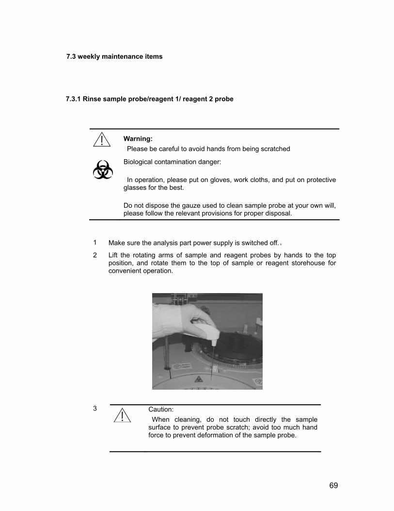
1 Make sure the analysis part power supply is switched off.。
2 Lift the rotating arms of sample and reagent probes by hands to the top position, and rotate them to the top of sample or reagent storehouse for convenient operation.
3
Caution: When cleaning, do not touch directly the sample surface to prevent probe scratch; avoid too much hand force to prevent deformation of the sample probe.

70
Note: Acidic and alkaline cleaning liquid can be used alternatively, for instance, acidic cleaning liquid is used at previous time maintenance, use alkaline cleaning liquid at this time maintenance.
Wipe the external walls of sample and reagent probes lightly with cotton stick moisturized with alcohol, especially the point of probe, until no impurities left at all.
4 Wipe sample and reagent probes with the gauze dipped with deionized
water
After cleaning, lift the rotating arms of sample and reagent probes to the top position, and rotate the rotating arm of sample probe to locate the sample probe above the rinsing bath of sample and reagent probes.
Caution: After cleaning the surface of a sample probe, please make sure sample probe must be rotated to the top of sample probe rinsing bath.
5
6 Switch on the power of analysis part and wait 30 seconds, enter the "maintenance - routine maintenance" column to implement “instrument resetting", the system will automatically reset the sample and reagent probes and rinse them with deionized water.
71
1 Make sure the analysis part power supply is switched off.。
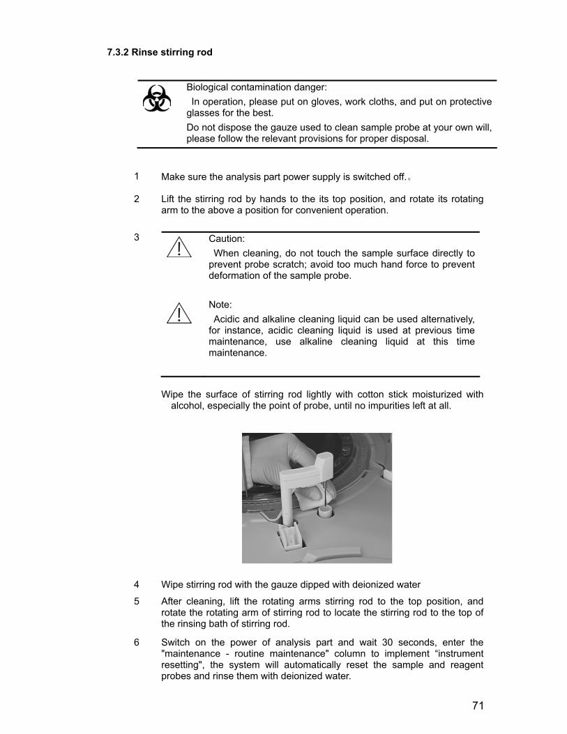
2 Lift the stirring rod by hands to the its top position, and rotate its rotating arm to the above a position for convenient operation.
3
Caution: When cleaning, do not touch the sample surface directly to prevent probe scratch; avoid too much hand force to prevent deformation of the sample probe.
Note: Acidic and alkaline cleaning liquid can be used alternatively, for instance, acidic cleaning liquid is used at previous time maintenance, use alkaline cleaning liquid at this time maintenance.
Wipe the surface of stirring rod lightly with cotton stick moisturized with alcohol, especially the point of probe, until no impurities left at all.
4 Wipe stirring rod with the gauze dipped with deionized water
5 After cleaning, lift the rotating arms stirring rod to the top position, and rotate the rotating arm of stirring rod to locate the stirring rod to the top of the rinsing bath of stirring rod.
6 Switch on the power of analysis part and wait 30 seconds, enter the "maintenance - routine maintenance" column to implement “instrument resetting", the system will automatically reset the sample and reagent probes and rinse them with deionized water.
7.3.2 Rinse stirring rod
Biological contamination danger: In operation, please put on gloves, work cloths, and put on protective glasses for the best. Do not dispose the gauze used to clean sample probe at your own will, please follow the relevant provisions for proper disposal.
72
小心: Caution:
Do not gaze scanning laser light, or it may cause eyes injury
1 Make sure the analysis part power is switched off.
2 Remove the reagent and sample disk covers, and then remove the sample and reagent disks.
3 Wipe the scanning glass window lightly with gauze dipped with deionized water.
4 Remount the sample and reagent disks and cover them.
5 Switch on the analysis part and wait 30 seconds, the system will reset automatically.
7.3.4 Rinse sample storehouse
Warning: Please be careful to avoid being scratched by sample probe.
Biological contamination danger: In operation, please put on gloves, work cloths, and put on protective glasses for the best. Do not dispose the gauze used to clean sample probe at your own will, please follow the relevant provisions for proper disposal.
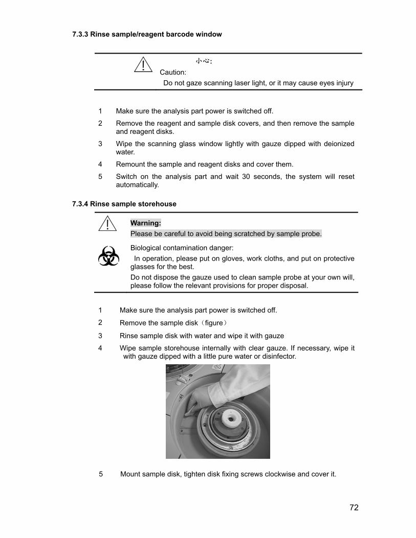
1 Make sure the analysis part power is switched off.
2 Remove the sample disk(figure)
3 Rinse sample disk with water and wipe it with gauze
4 Wipe sample storehouse internally with clear gauze. If necessary, wipe it with gauze dipped with a little pure water or disinfector.
7.3.3 Rinse sample/reagent barcode window
5 Mount sample disk, tighten disk fixing screws clockwise and cover it.
73
7.3.5 Rinse reagent refrigeration storehouse
Warning: Please be careful to avoid being scratched by sample probe.
Biological contamination danger: In operation, please put on gloves, work cloths, and put on protective glasses for the best.
Do not dispose the gauze used to clean sample probe at your own will, please follow the relevant provisions for proper disposal.
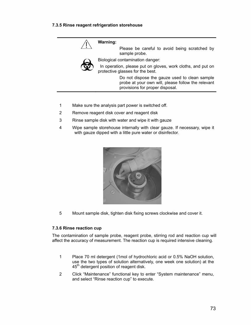
1 Make sure the analysis part power is switched off.
2 Remove reagent disk cover and reagent disk
3 Rinse sample disk with water and wipe it with gauze
4 Wipe sample storehouse internally with clear gauze. If necessary, wipe it with gauze dipped with a little pure water or disinfector.
5 Mount sample disk, tighten disk fixing screws clockwise and cover it.
7.3.6 Rinse reaction cup
The contamination of sample probe, reagent probe, stirring rod and reaction cup will affect the accuracy of measurement. The reaction cup is required intensive cleaning.
1 Place 70 ml detergent (1mol of hydrochloric acid or 0.5% NaOH solution,
use the two types of solution alternatively, one week one solution) at the 45th detergent position of reagent disk.
2 Click “Maintenance” functional key to enter “System maintenance” menu, and select “Rinse reaction cup” to execute.

7.4.1 Rinse sample,
74
7.4 Monthly maintenance item
reagent 1, reagent 2 probe rinsing bath.
Warning: Please be careful to avoid being scratched by sample probe.
Biological contamination danger: In operation, please put on gloves, work cloths, and put on protective glasses for the best.
Do not dispose the gauze used to clean sample probe at your own will, please follow the relevant provisions for proper disposal.
1 Make sure the analysis part power is switched off.
2 Lift the rotating arm of sample probe by hands to the its top position, and rotate its rotating arm to keep sample probe away from rinsing bath for convenient operation.
3 Clean the inside and appearance of sample probe rinsing bath with clean cotton stick.
4 After cleaning, lift the rotating arm of sample probe to the top position, and rotate the rotating arm of stirring rod to locate the sample probe to the top of the rinsing bath of sample probe.
Caution: After the work of sample probe surface rinsing, please make sure to rotate the sample probe to the top of sample probe rinsing bath.
5 Switch on the power of analysis part and wait 30 seconds, enter the "maintenance - routine maintenance" column to implement “instrument resetting", the system will automatically reset the sample and reagent probes and rinse them with deionized water.
75
Warning: Please be careful to avoid being scratched by sample probe.
Biological contamination danger: In operation, please put on gloves, work cloths, and put on protective glasses for the best.
Do not dispose the gauze used to clean sample probe at your own will, please follow the relevant provisions for proper disposal.
1 Make sure the analysis part power is switched off.
2 Lift the stirring arm to the top position by hand to one side of rinsing bath.
3 Wipe stirring rod with clean soft gauze.
7.5 Every 4-6 months maintenance item
7.5.1 Dust-proof disposal of cooling unit 1 Make sure the analysis part power is switched off.
2 Open right back cover board
3 Remove the three screws of cooling unit and remove the cooling unit.
4 Remove the dustproof from the cooling unit and rinse it with water and dry it.
(figure)
5 Remount dustproof net cleaned already.
6 Mount back cover board
7.4.2 Rinse stirring rod rinsing bath

76
Caution:
Please use consumables recommended by Dirui company, using other consumables may cause system performance degradation. Do not touch the light source lamp shell surface and lens in front of the light source lamp by hand, because it may change the characteristics of the light source. If you accidentally make noodle stained with filth, absorbent cotton dipped by absolute alcohol can be used to clean it.
1 Turn off the system main power, so that the light source box and light
source lamp will be cooled for at least 15 minutes.
Warning: High-temperature light source lamp and light box will cause burn. Operation is carried out only after the light source and light source lamp are cooled.
2 Loosen the fixing screws of rinsing mechanism; remove the rinsing
mechanism of reaction cup. Loosen the setscrews of reaction disk and
remove the reaction disk. Place the reaction cup at dry and clean position.
Loosen the two fixing wire connecting poles of halogen and remove
down-lead.
7.6 Every half a year maintenance item
7.6.1 Check light source lamp
Lamp light source of optical system will gradually be aged in use, and will cause an increase in noise measurements. If the cup blank and light source intensity attenuation is out of range or the working time of light source lamp accumulates over 2000 hours, the light source lamp should be checked.
77
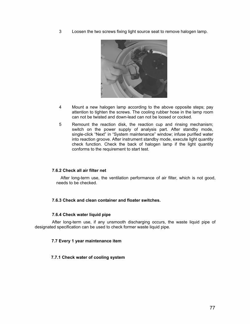
3 Loosen the two screws fixing light source seat to remove halogen lamp.
4 Mount a new halogen lamp according to the above opposite steps; pay attention to tighten the screws. The cooling rubber hose in the lamp room can not be twisted and down-lead can not be loosed or cocked.
5 Remount the reaction disk, the reaction cup and rinsing mechanism; switch on the power supply of analysis part. After standby mode, single-click “Next” in “System maintenance” window; infuse purified water into reaction groove. After instrument standby mode, execute light quantity check function. Check the back of halogen lamp if the light quantity conforms to the requirement to start test.
7.6.2 Check all air filter net After long-term use, the ventilation performance of air filter, which is not good, needs to be checked.
7.6.3 Check and clean container and floater switches.
7.6.4 Check water liquid pipe
After long-term use, if any unsmooth discharging occurs, the waste liquid pipe of designated specification can be used to check former waste liquid pipe.
7.7 Every 1 year maintenance item
7.7.1 Check water of cooling system
78
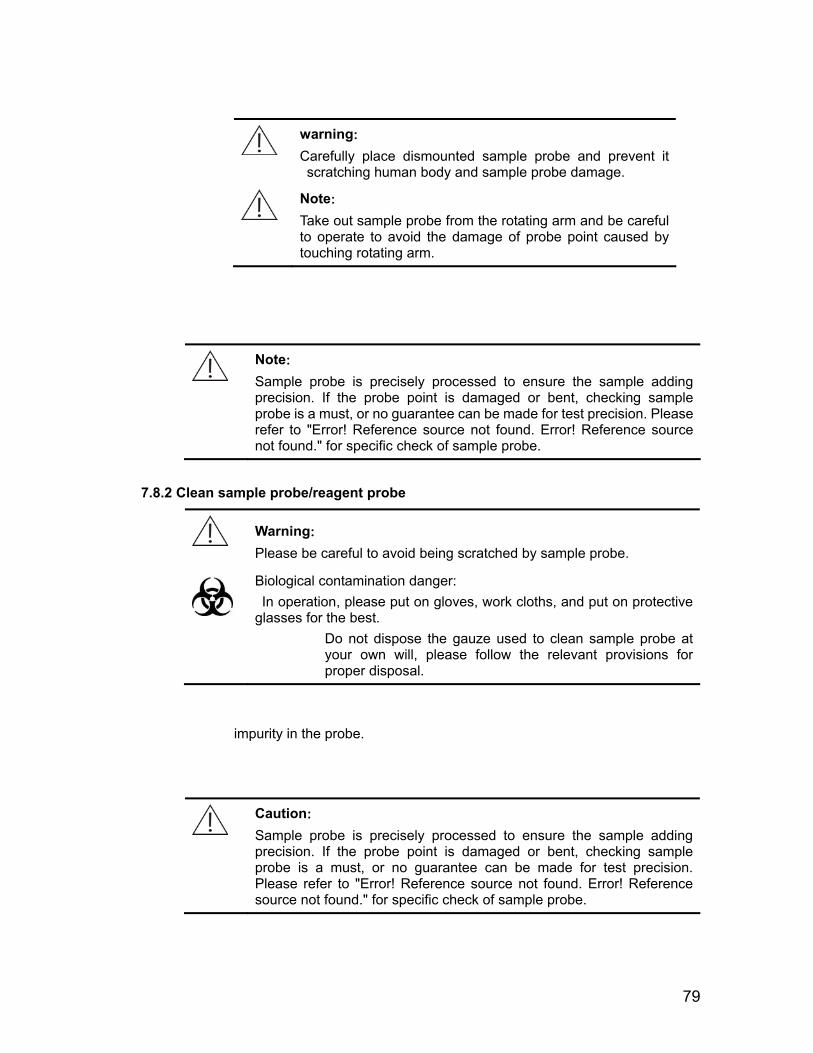
5 Loosen pipeline interface
Warning: Please be careful to avoid being scratched by sample probe.
Biological contamination danger: In operation, please put on gloves, work cloths, and put on protective glasses for the best.
Do not dispose the gauze used to clean sample probe at your own will, please follow the relevant provisions for proper disposal.
1 Make sure the analysis part power is switched off.
2 Remove sample disk cover and then sample disk
3 Lift the rotating arm of sample probe by hands to its top position, and rotate its rotating arm to keep sample probe away from rinsing bath for convenient operation.
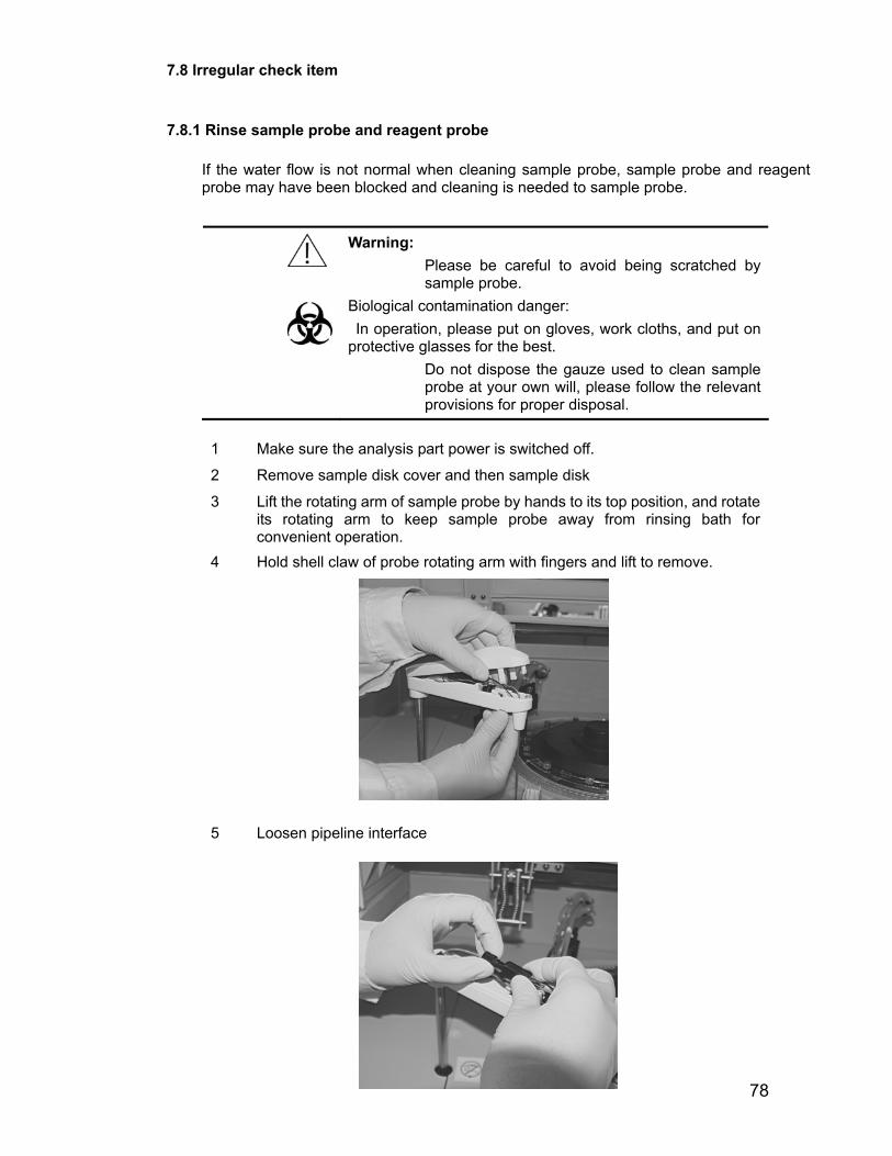
4 Hold shell claw of probe rotating arm with fingers and lift to remove.
7.8 Irregular check item
7.8.1 Rinse sample probe and reagent probe
If the water flow is not normal when cleaning sample probe, sample probe and reagent probe may have been blocked and cleaning is needed to sample probe.
79
warning: Carefully place dismounted sample probe and prevent it scratching human body and sample probe damage.
Note: Take out sample probe from the rotating arm and be careful to operate to avoid the damage of probe point caused by touching rotating arm.
Note: Sample probe is precisely processed to ensure the sample adding precision. If the probe point is damaged or bent, checking sample probe is a must, or no guarantee can be made for test precision. Please refer to "Error! Reference source not found. Error! Reference source not found." for specific check of sample probe.
7.8.2 Clean sample probe/reagent probe
impurity in the probe.
Caution: Sample probe is precisely processed to ensure the sample adding precision. If the probe point is damaged or bent, checking sample probe is a must, or no guarantee can be made for test precision. Please refer to "Error! Reference source not found. Error! Reference source not found." for specific check of sample probe.
Warning: Please be careful to avoid being scratched by sample probe.
Biological contamination danger: In operation, please put on gloves, work cloths, and put on protective glasses for the best.
Do not dispose the gauze used to clean sample probe at your own will, please follow the relevant provisions for proper disposal.
80
7.8.3 Install sample/reagent probe
Warning:
Please be careful to avoid being scratched by sample probe.
Biological contamination danger: In operation, please put on gloves, work cloths, and put on protective glasses for the best
Dismounting sequence is opposite to that of sample probe/reagent probe.
Caution:
Sample probe is precisely processed to ensure the sample adding precision. If the probe point is damaged or bent, checking sample probe is a must, or no guarantee can be made for test precision. Please refer to "Error! Reference source not found. Error! Reference source not found." for specific check of sample probe.
7.8.4 Rinse sample probe/reagent
When it is found that the water level of rinsing bath is too high when rinsing sample probe because of no discharging available, which may be caused by the blocked leaking hole. Cleaning sample rinsing bath is necessary.
Warning:
Please be careful to avoid being scratched by sample probe.
Biological contamination danger: In operation, please put on gloves, work cloths, and put on protective glasses for the best
1 Make sure the analysis part power is switched off.
2 Lift the rotating arm of sample probe by hands to its top position, and rotate its rotating arm to keep sample probe away from rinsing bath for convenient operation.
3 Infuse about 1ml alkaline detergent of 0.5% (V / V) sodium hypochlorite or 84 disinfectant into rinsing bath for 10 minutes.
4 Switch on the power supply of analysis part
5 Lift the rotating arm of sample probe by hands to its top position, and rotate its rotating arm to keep sample probe above the rinsing bath of sample probe.
Caution:Please rotate the sample probe to the top of sample probe rinsing bath after clean rinsing bath of sample probe.
6 Select and execute “Instrument resetting” after enter “Maintenance-routine maintenance”, and the system will reset sample probe and sample probe and rinsing bath will be rinsed with deionized water automatically. Observe the outflow of sample probe rinsing bath.
81
7.8.5 Rinse stirring rod
If the stirring rod is damaged, please check stirring rod in accordance with following steps strictly.
Warning:
Please be careful to avoid being scratched by sample probe. Any touch is forbidden except at the knurling of it only by hand when checking, and prevent any scratch on the flat part of stirring part.
Biological contamination danger: In operation, please put on gloves, work cloths, and put on protective glasses for the best Please deal with removed stirring rod properly.
Caution:
Please use consumables recommended by Dirui company, using other consumables may cause system performance degradation.
1 Make sure the analysis part power is switched off.
2 Prepare a new stirring rod and wipe the flat part of it with gauze or cotton stick dipped with cleaning liquid, and then wipe it with gauze dipped with deionized water.
3 Lift the rotating arm of stirring rod by hands to its top position, and rotate its rotating arm for convenient operation.

82
4
Caution: When pulling out stirring rod, make sure the direction of force is vertical to that of axis of rotating arm. Lateral force may damage the axis or stirring rod.
Remove stirring rod after loosen the two fixing screws.
5 Prepare a new stirring rod, and wipe the front of the stirring rod with gauze
dipped with 2% CS-antibacterial cleaning liquid.
6 When mounting new stirring rod, insert stirring rod till the bottom of motor axis and tighten it with M2 screw.
Caution: When inserting stirring rod, make sure the direction of force is vertical to that of axis of rotating arm. Lateral force may damage the axis or stirring rod. Pushing the stirring rod completely
7 After stirring rod check, visually check whether stirring rod and its rotating arm are vertical with each other.
If not vertical, return to step 5 and remount the stirring rod.
If vertical, continue to next.
8 Lift the rotating arm of stirring rod by hands to its top position, and rotate its rotating arm to the top of its rinsing bath.
Caution: Please make sure to rotate stirring rod to its rinsing bath top after mount it.
9 Switch on the power of analysis part and wait 30 seconds, enter the
"maintenance - routine maintenance" column to implement “instrument resetting", the system will automatically reset the sample probe and rinse it with deionized water. Observe the outflow of sample probe.
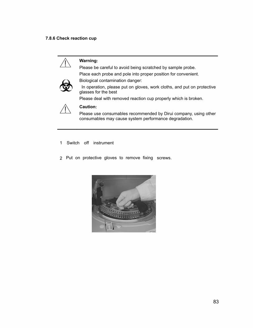
83
1 Switch off instrument
7.8.6 Check reaction cup
Warning:
Please be careful to avoid being scratched by sample probe. Place each probe and pole into proper position for convenient.
Biological contamination danger: In operation, please put on gloves, work cloths, and put on protective glasses for the best Please deal with removed reaction cup properly which is broken.
Caution:
Please use consumables recommended by Dirui company, using other consumables may cause system performance degradation.
2 Put on protective gloves to remove fixing screws.

84
3 Rotate reaction disk by hand and remove the reaction cup sequently. Take out reaction cup while rotating it.
4 Rinse the new reaction cup dipped in with water; rinse inside and outside of reaction and no scratch is allowed.
5 Rotate reaction disk by hands, and mount new reaction cup on reaction disk and check the six sets reaction cups simultaneously.
6 Mount reaction disk with the opposite steps and make sure the fixing screw of reaction disk is tight.
7 Switch on the power of analysis part
Select and execute “cup blank test” after click “System maintenance”, and observe execution result and reaction status.
85
Chapter 8 Assay Method
CS-400 adopting three analytical methods as follows:
point assay
two-point assay
rate assay
8.1 Analysis principle
The assay mode of Auto-Chemistry Analyzer is based on the Beer-Lambert law that the material selective absorption light
The main principle is: When monochromatic light with specific wavelength passes through the cuvette with sample, the monochromatic light absorbency and sample liquid concentration are varies directly as the distance which is passed through sample liquid by light:
c
b
IIlg1/TlgA 0 ε=== )()(
t
A -Absorbency of the light when passing through liquid
T -Transmitted intensity and incident intensity ratio: transmittance It/I0;
I0
- Incident intensity
It
- Transmitted intensity
ε
- Molar absorption coefficient of solution(ml×mmol-1×cm-1);
c - Mol concentration of the solution(mmol/ml);
b
- Solution layer thickness(cm);
Solution layer thickness (b): Optical path, which is fixed by instrument. Molar absorption coefficient (ε) is the correlation coefficient of the wavelength, solution and solution temperature. Linear relationship is displayed between solution thickness and absorbency when in stable temperature and single wavelength(ε value is given on the reagent bottle by factory)
If the sample liquid adequate distribution, interaction between liquid and incidence monochromatic light only happens during absorbing process. No fluorescence, disperse and photochemical appear. No interaction between substances in the solution while absorbing process. The absorbency possess conducts nature, and this condition conforms to the Beer-Lambert law
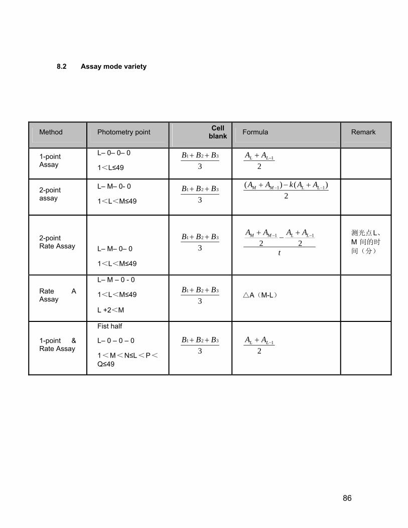
86
8.2 Assay mode variety
Method Photometry point Cell blank Formula Remark
1-point Assay
L– 0– 0– 0
1<L≤49
1 2 3
3B B B+ +
21−+ LL AA
2-point assay
L– M– 0- 0
1<L<M≤49
1 2 3
3B B B+ +
1 1( ) ( )2
M M L LA A k A A− −+ − +
2-point Rate Assay
L– M– 0– 0
1<L<M≤49
1 2 3
3B B B+ +
1 1
2 2M M L LA A A A
t
− −+ +−
测光点L、M 间的时
间(分)
Rate A Assay
L– M – 0 - 0
1<L<M≤49
L +2<M
1 2 3
3B B B+ +
A△ (M-L)
1-point & Rate Assay
Fist half
L– 0 – 0 – 0
1<M<N≤L<P<Q≤49
1 2 3
3B B B+ +
21−+ LL AA
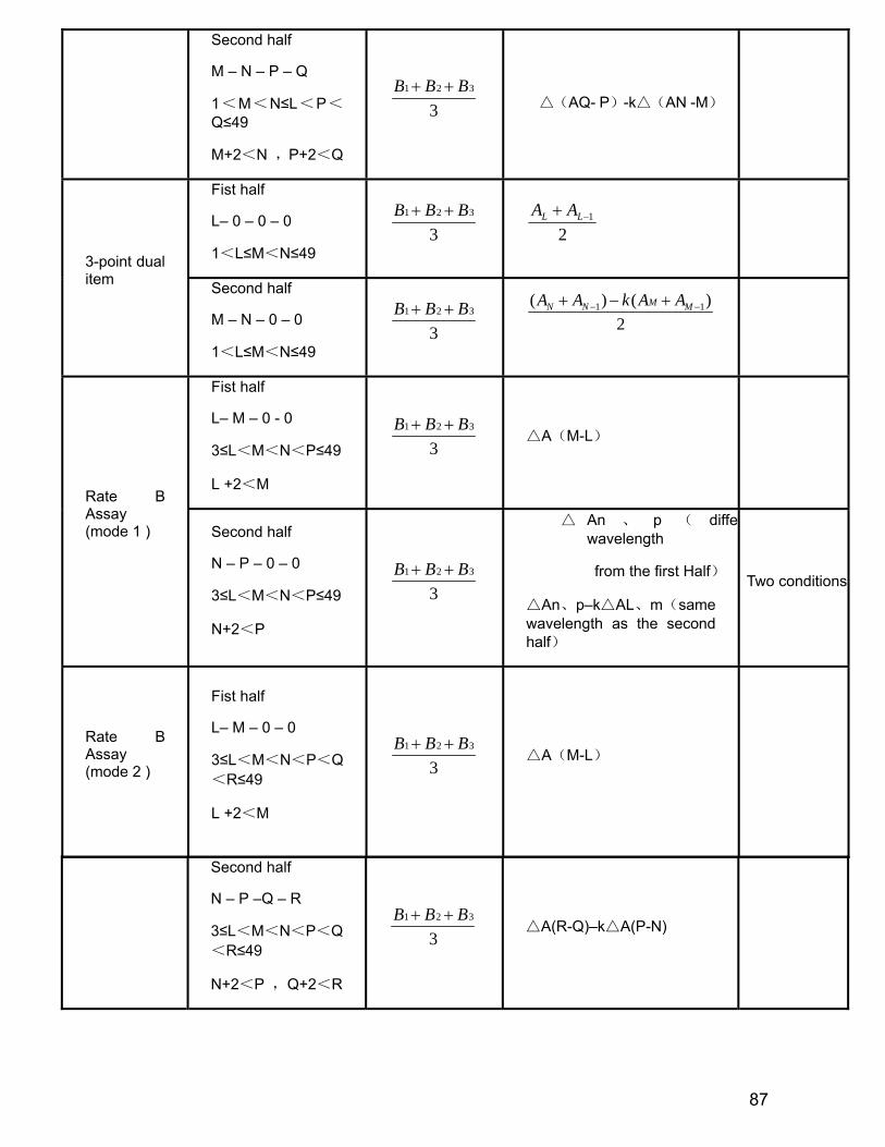
87
Second half
M – N – P – Q
1<M<N≤L<P<Q≤49
M+2<N ,P+2<Q
1 2 3
3B B B+ +
△(AQ- P)-k△(AN -M)
Fist half
L– 0 – 0 – 0
1<L≤M<N≤49
1 2 3
3B B B+ +
21−+ LL AA
3-point dual item Second half
M – N – 0 – 0
1<L≤M<N≤49
1 2 3
3B B B+ +
1 1( ) ( )2
MN N MA A k A A− −+ − +
Fist half
L– M – 0 - 0
3≤L<M<N<P≤49
L +2<M
1 2 3
3B B B+ +
A△ (M-L)
Rate B Assay (mode 1 ) Second half
N – P – 0 – 0
3≤L<M<N<P≤49
N+2<P
1 2 3
3B B B+ +
△ An 、 p ( diffewavelength
from the first Half)
An△ 、p–k AL△ 、m(same wavelength as the second half)
Two conditions
Rate B Assay (mode 2 )
Fist half
L– M – 0 – 0
3≤L<M<N<P<Q<R≤49
L +2<M
1 2 3
3B B B+ +
A△ (M-L)
Second half
N – P –Q – R
3≤L<M<N<P<Q<R≤49
N+2<P ,Q+2<R
1 2 3
3B B B+ +
A(R△ -Q)–k A(P△ -N)
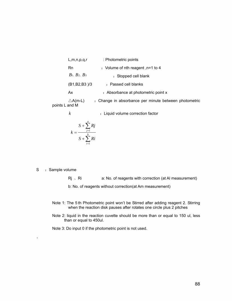
88
L,m,n,p,q,r : Photometric points
Rn :Volume of nth reagent ,n=1 to 4
1 2 3B B B、 、 :Stopped cell blank
(B1,B2,B3 )/3 :Passed cell blanks
Ax :Absorbance at photometric point x
△A(m-L) :Change in absorbance per minute between photometric points L and M
k :Liquid volume correction factor
∑
∑
=
=
+
+= b
i
a
j
RiS
RjSk
1
1
S :Sample volume
Rj 、Ri a: No. of reagents with correction (at Al measurement)
b: No. of reagents without correction(at Am measurement)
Note 1: The 5 th Photometric point won’t be Stirred after adding reagent 2. Stirring when the reaction disk pauses after rotates one circle plus 2 pitches
Note 2: liquid in the reaction cuvette should be more than or equal to 150 ul, less than or equal to 450ul.
Note 3: Do input 0 if the photometric point is not used.
。
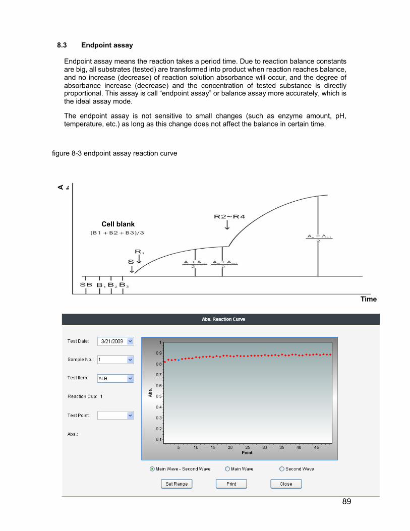
89
proportional. This assay is call “endpoint assay” or balance assay more accurately, which is the ideal assay mode.
The endpoint assay is not sensitive to small changes (such as enzyme amount, pH, temperature, etc.) as long as this change does not affect the balance in certain time.
figure 8-3 endpoint assay reaction curve
Time
Cell blank
A b
8.3 Endpoint assay
Endpoint assay means the reaction takes a period time. Due to reaction balance constants are big, all substrates (tested) are transformed into product when reaction reaches balance, and no increase (decrease) of reaction solution absorbance will occur, and the degree of absorbance increase (decrease) and the concentration of tested substance is directly
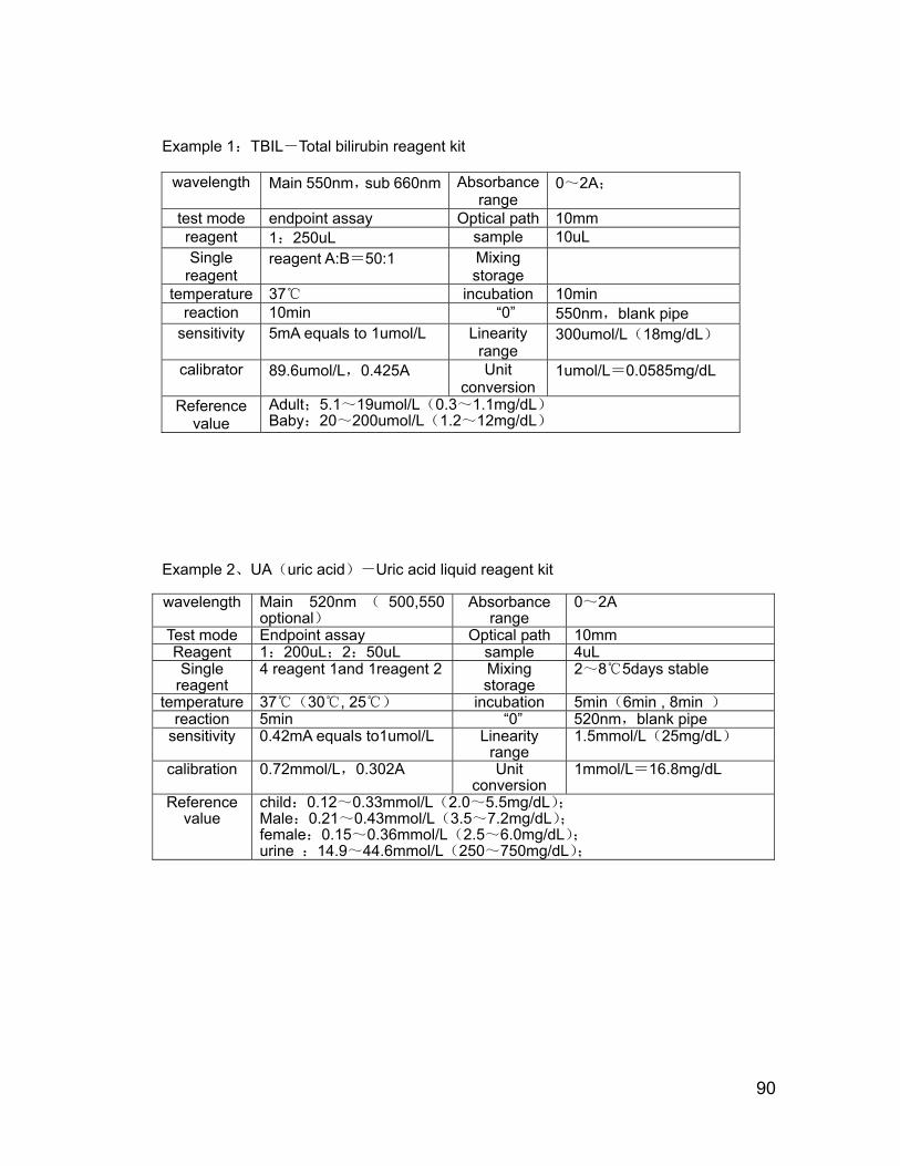
90
Example 1:TBIL-Total bilirubin reagent kit
Example 2、UA(uric acid)-Uric acid liquid reagent kit
wavelength Main 520nm ( 500,550 optional)
Absorbance range
0~2A
Test mode Endpoint assay Optical path 10mm Reagent 1:200uL;2:50uL sample 4uL Single
reagent 4 reagent 1and 1reagent 2 Mixing
storage 2~8℃5days stable
temperature 37℃(30℃, 25℃) incubation 5min(6min , 8min )
reaction 5min “0” 520nm,blank pipe sensitivity 0.42mA equals to1umol/L Linearity
range 1.5mmol/L(25mg/dL)
calibration 0.72mmol/L,0.302A Unit conversion
1mmol/L=16.8mg/dL
Reference value
child:0.12~0.33mmol/L(2.0~5.5mg/dL);
Male:0.21~0.43mmol/L(3.5~7.2mg/dL);
female:0.15~0.36mmol/L(2.5~6.0mg/dL);
urine :14.9~44.6mmol/L(250~750mg/dL);
wavelength Main 550nm,sub 660nm Absorbance range
0~2A;
test mode endpoint assay Optical path 10mm reagent 1:250uL sample 10uL Single
reagent reagent A:B=50:1 Mixing
storage
temperature 37℃ incubation 10min reaction 10min “0” 550nm,blank pipe
sensitivity 5mA equals to 1umol/L Linearity range
300umol/L(18mg/dL)
calibrator 89.6umol/L,0.425A Unit conversion
1umol/L=0.0585mg/dL
Reference value
Adult;5.1~19umol/L(0.3~1.1mg/dL) Baby:20~200umol/L(1.2~12mg/dL)

91
8.4 2-point assay
2-point assay (fixed time assay) is also called first class dynamics assay, which means the reaction speed is in direct proportion to the simple power of substrate concentration in specified time, namely v=k[S]. Due to the reduction of substrate, the whole reaction speed is decreasing gradually, which reflects the decrease (increase) of absorbance and decrease of speed. Because reaction time to reach balance is very long, , it can be monitored at any time theoretically, but because of the complexity of serum ingredient and much reaction, therefore, it takes a certain period of time to enter in stable reaction phase.
Figure 8-2 2-point assay reaction curve
2-point assay 2-point rate assay
8.5 Rate assay
Rate assay, also known as zero-class dynamics assay, refers to the reaction rate is directly proportional to the zero power of substrate concentration, which has nothing to do with the substrate concentration. Hence, the reactants can generate a certain product at constant speed throughout the reaction process, resulting in even decrease or increase of absorbance of measured solution at a wavelength, and the decrease or increase speed ( △A / min) is directly proportional to the activity or concentration of the tested substance (catalytic material). Dynamics assay is also called as the continuous monitoring assay, mainly used for the measurement of enzyme activity.
In fact, because substrate concentration can not be big enough, with the reaction proceeding, the reaction is no longer zero class when substrate is consumed to a certain extent, Therefore, zero-class dynamics assay is targeted at a specific period in terms of time; Because reaction time to reach balance is very long, , it can be monitored at any time theoretically, but because of the complexity of serum ingredient and much reaction, therefore, it takes a certain period of time to enter in stable reaction phase. So all reagent manufactures have strict requirements to the two periods
Dynamics assay is based on the changes between specified photometric points to obtain the absorbance concentration or activity value.
Metering point in accordance with the input form, dynamics method can be divided into single-band and dual-band dynamics assay.
Cell blank
Reaction limit level Absorbance
Absorbance
Time Time

92
Absorbance
Figure 8-3 Rate assay reaction curve
Example 3:ALT/GPT - Alanine aminotransferase (IFCC)
wavelength Main 340nm Absorbance range
0~2A
Test mode Rate assay Optical path 10mm Reagent 1:200uL;2:50uL sample 15uL Single
reagent 4 reagent 1and 1reagent 2 Mixing
storage 2~8 5days stable℃
temperature 37℃(30 , 25℃ ℃) incubation 5min reaction 60s delay,measure 60-
120s “0” 340nm,blank pipe
sensitivity 0.30mA/min equals to 1.0U/L
Linearity range
450U/L(7.5ukat/L)
calibration Unit conversion
1U/L=16.67×10-3ukat/L
Reference value
37℃:Male:<40U/L(<0.67ukat/L);Female:<31U/L(<0.52ukat/L)
Calculating method:
P*SV*6.221000*TV*A/min
/L)=(UALT
TV=The total reaction volume (mL)
SV=sample volume(mL)
P=optical path of colorimetric cup(cm)
6.22=NADH position mmol extinction coefficient at 340nm (334nm:6.18,365nm:3.40)
Time
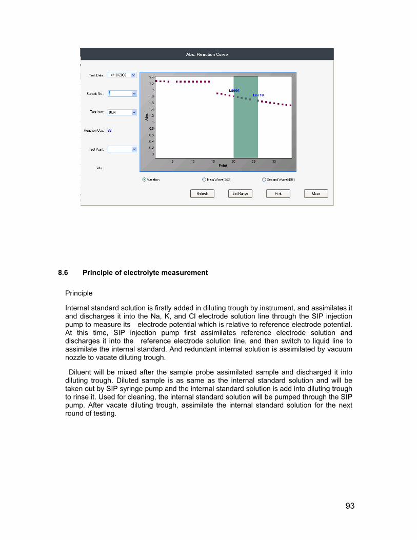
93
8.6 Principle of electrolyte measurement
Principle
Internal standard solution is firstly added in diluting trough by instrument, and assimilates it and discharges it into the Na, K, and Cl electrode solution line through the SIP injection pump to measure its electrode potential which is relative to reference electrode potential. At this time, SIP injection pump first assimilates reference electrode solution and discharges it into the reference electrode solution line, and then switch to liquid line to assimilate the internal standard. And redundant internal solution is assimilated by vacuum nozzle to vacate diluting trough.
Diluent will be mixed after the sample probe assimilated sample and discharged it into diluting trough. Diluted sample is as same as the internal standard solution and will be taken out by SIP syringe pump and the internal standard solution is add into diluting trough to rinse it. Used for cleaning, the internal standard solution will be pumped through the SIP pump. After vacate diluting trough, assimilate the internal standard solution for the next round of testing.
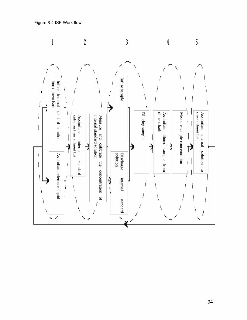
94
Figure 8-4 ISE Work flow
Infuse internal standard solution into diluent bath
Assim
ilate internal
standard solution
fromdiluentbath
Measure
and calibrate
the concentration
of internal standard solution
Infuse sample
Diluting sam
ple
Assim
ilate diluted
sample
from
diluent bath
Measure sam
ple concentration
Assim
ilate internal
solution to
rinsediluentbath
Assim
ilate reference liquid
Discharge
internal standard
solution
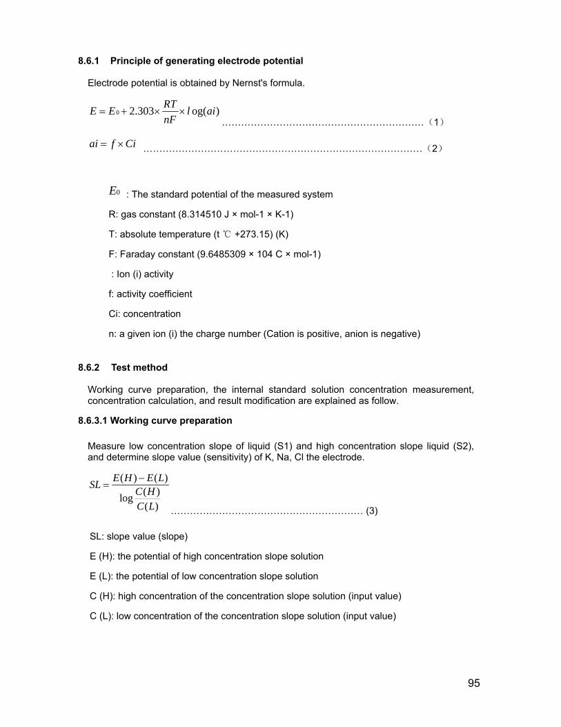
95
8.6.1 Principle of gene
rating electrode potential
Electrode potential is obtained by Nernst's formula.
0 2.303 og( )RTE E l ainF
= + × ×………………………………………………………(1)
ai f Ci= × ……………………………………………………………………………(2)
0E : The standard potential of the measured system
R: gas constant (8.314510 J × mol-1 × K-1)
T: absolute temperature (t +273.15) (K) ℃
F: Faraday constant (9.6485309 × 10⁴ C × mol-1)
: Ion (i) activity
f: activity coefficient
Ci: concentration
n: a given ion (i) the charge number (Cation is positive, anion is negative)
8.6.2 Test method
Working curve preparation, the internal standard solution concentration measurement, concentration calculation, and result modification are explained as follow.
8.6.3.1 Working curve preparation
Measure low concentration slope of liquid (S1) and high concentration slope liquid (S2), and determine slope value (sensitivity) of K, Na, Cl the electrode.
( ) ( )( )log( )
E H E LSL C HC L
−=
…………………………………………………… (3)
SL: slope value (slope)
E (H): the potential of high concentration slope solution
E (L): the potential of low concentration slope solution
C (H): high concentration of the concentration slope solution (input value)
C (L): low concentration of the concentration slope solution (input value)

96
8.6.3.2 The measurement of internal liquid concentration
( ) ( )
( ) ( ) 10E IS E L
SLC IS C L−
= × …………………………………………… (4)
C (IS): the concentration of internal standard solution
E (IS): the potential of internal standard solution
8.6.3.3 concentration calculation
The calculation of routine sample, STAT sample, and concentration of quality control liquid is based on the concentration of internal standard solution. Internal standard solution is different with the different sample.
( ) ( )
( ) ( ) 10E S E IS
SLC S C IS−
= × ………………………………………… (5)
C(S):Sample concentration
E(S): Sample potential
8.6.3.4 result modification
Test calibrator (calibrator S3)of serum category after calibration to calculate its concentration, and the difference between the tested concentration and input value is used as compensation value to increase or decrease sample quantitative value.
( ) ( ) ( )C VALUE C C C X= − ………………………………………… (6)
C (VALUE): compensation value (compensation value)
C (C): Concentration input value of the serum calibrator
C (X): Concentration tested value of the serum calibrator
{ }' ( ) ( ) ( )C S IF C S C VALUE= +.. ... ... ... ... ... ... ... ... ... ... ... ... ... (7)
C '(S): modified sample concentration
IF: Instrument constant (usually 1.0)
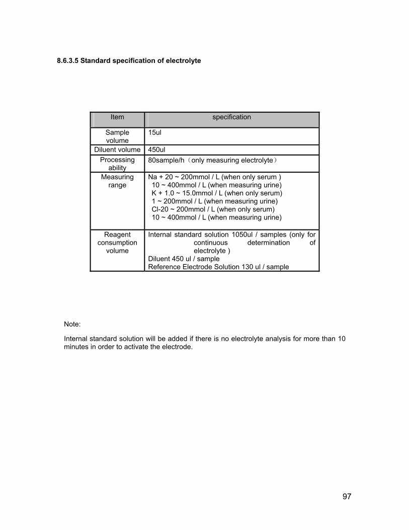
97
8.6.3.5
Standard specification of electrolyte
Item specification
Sample volume
15ul
Diluent volume 450ul Processing
ability 80sample/h(only measuring electrolyte)
Measuring range
Na + 20 ~ 200mmol / L (when only serum ) 10 ~ 400mmol / L (when measuring urine) K + 1.0 ~ 15.0mmol / L (when only serum) 1 ~ 200mmol / L (when measuring urine) Cl-20 ~ 200mmol / L (when only serum) 10 ~ 400mmol / L (when measuring urine)
Reagent consumption
volume
Internal standard solution 1050ul / samples (only for continuous determination of electrolyte )
Diluent 450 ul / sample Reference Electrode Solution 130 ul / sample
Note:
Internal standard solution will be added if there is no electrolyte analysis for more than 10 minutes in order to activate the electrode.

98
Chapter 9 Malfunction Analysis
9.1 Stirring mechanism 1
Alarm Code Description Detailed
description Solution
1-1 R1stirring mechanism abnormal
R1stirring mechanism fails to reach the top of rinsing bath side.
In the CS-400 upper instrument software, enter into the "system maintenance" interface after on-line, implement "mechanical movement check", and observe the stirring rod running status
Malfunction 1:stirring mechanism stops
Solution:
1, Check stirring mechanism up-down movements, mechanical repair is required if resistance is big.
2, check whether both ends of connector of the motor are connected well.
3, check whether the conductivity of motor lead wire is good.
4, check the motor drive module of circuit board is working normally
Malfunction 2:stirring mechanism can reach the top, but can not check the zero position.
solution:Manually make stirring mechanism repeatedly rise to peak, and observe ud_st1 adapter indicator status.
1、sparkling of ud_st1 indicator means the wiring of light sensor and adaptor is normal.
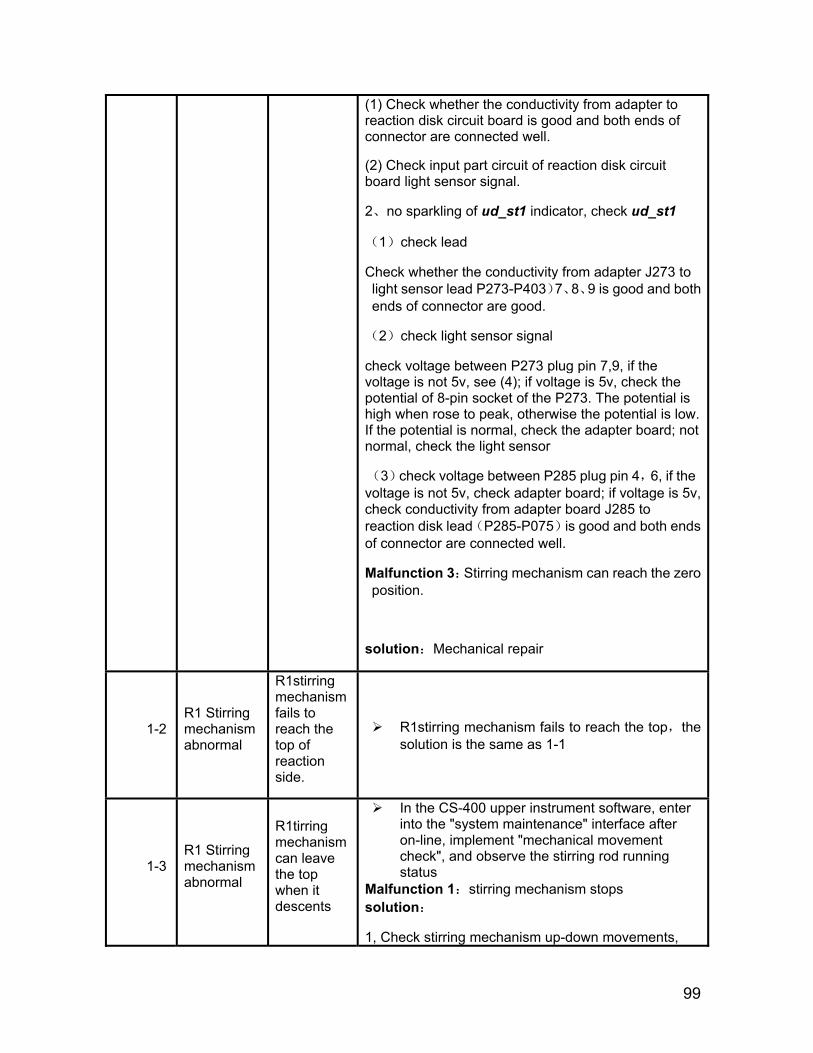
99
(1) Check whether the conductivity from adapter to reaction disk circuit board is good and both ends of connector are connected well.
(2) Check input part circuit of reaction disk circuit board light sensor signal.
2、no sparkling of ud_st1 indicator, check ud_st1
(1)check lead
Check whether the conductivity from adapter J273 to light sensor lead P273-P403)7、8、9 is good and both ends of connector are good.
(2)check light sensor signal
check voltage between P273 plug pin 7,9, if the voltage is not 5v, see (4); if voltage is 5v, check the potential of 8-pin socket of the P273. The potential is high when rose to peak, otherwise the potential is low. If the potential is normal, check the adapter board; not normal, check the light sensor
(3)check voltage between P285 plug pin 4,6, if the voltage is not 5v, check adapter board; if voltage is 5v, check conductivity from adapter board J285 to reaction disk lead(P285-P075)is good and both ends of connector are connected well.
Malfunction 3:Stirring mechanism can reach the zero position.
solution:Mechanical repair
1-2 R1 Stirring mechanism abnormal
R1stirring mechanism fails to reach the top of reaction side.
R1stirring mechanism fails to reach the top,the solution is the same as 1-1
1-3 R1 Stirring mechanism abnormal
R1tirring mechanism can leave the top when it descents
In the CS-400 upper instrument software, enter into the "system maintenance" interface after on-line, implement "mechanical movement check", and observe the stirring rod running status
Malfunction 1:stirring mechanism stops solution:
1, Check stirring mechanism up-down movements,
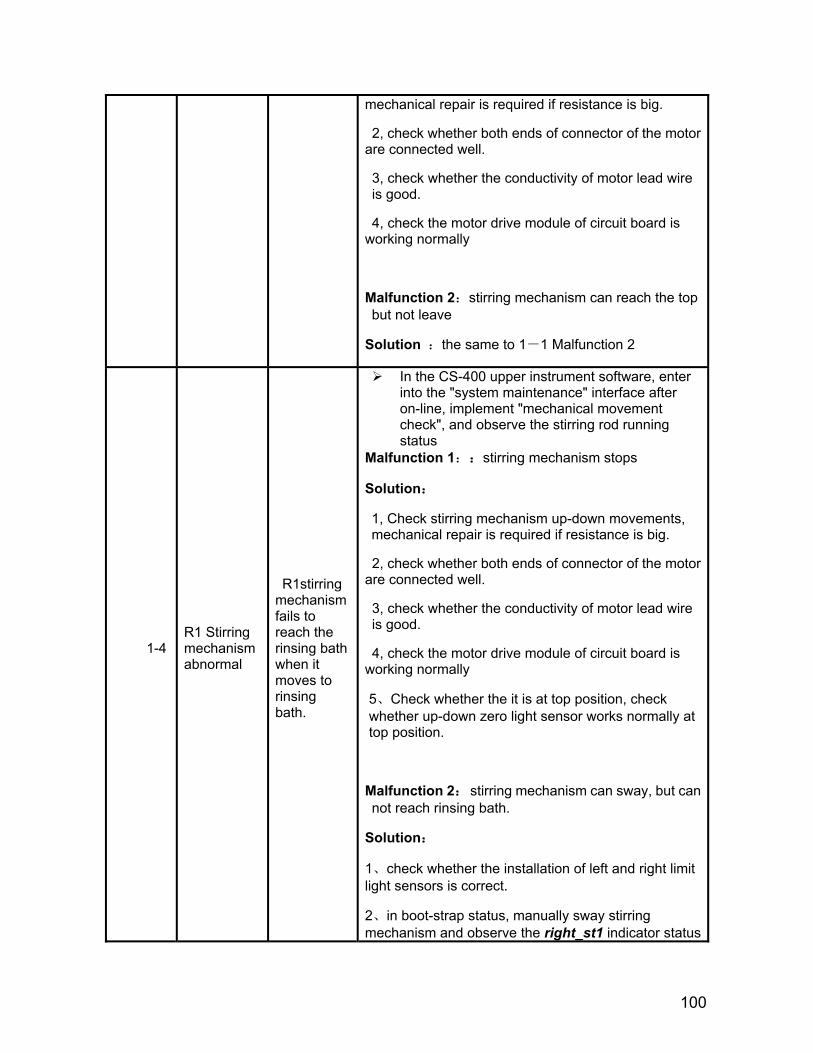
100
mechanical repair is required if resistance is big.
2, check whether both ends of connector of the motor are connected well.
3, check whether the conductivity of motor lead wire is good.
4, check the motor drive module of circuit board is working normally
Malfunction 2:stirring mechanism can reach the top but not leave
Solution :the same to 1-1 Malfunction 2
1-4 R1 Stirring mechanism abnormal
R1stirring mechanism fails to reach the rinsing bath when it moves to rinsing bath.
In the CS-400 upper instrument software, enter into the "system maintenance" interface after on-line, implement "mechanical movement check", and observe the stirring rod running status
Malfunction 1::stirring mechanism stops
Solution:
1, Check stirring mechanism up-down movements, mechanical repair is required if resistance is big.
2, check whether both ends of connector of the motor are connected well.
3, check whether the conductivity of motor lead wire is good.
4, check the motor drive module of circuit board is working normally
5、Check whether the it is at top position, check whether up-down zero light sensor works normally at top position.
Malfunction 2: stirring mechanism can sway, but can not reach rinsing bath.
Solution:
1、check whether the installation of left and right limit light sensors is correct.
2、in boot-strap status, manually sway stirring mechanism and observe the right_st1 indicator status
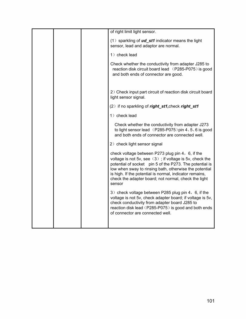
101
of right limit light sensor.
(1)sparkling of ud_st1 indicator means the light sensor, lead and adaptor are normal.
1)check lead
Check whether the conductivity from adapter J285 to reaction disk circuit board lead (P285-P075)is good and both ends of connector are good.
2)Check input part circuit of reaction disk circuit board light sensor signal.
(2)if no sparkling of right_st1,check right_st1
1)check lead
Check whether the conductivity from adapter J273 to light sensor lead (P285-P075)pin 4、5、6 is good and both ends of connector are connected well.
2)check light sensor signal
check voltage between P273 plug pin 4,6, if the voltage is not 5v, see(3); if voltage is 5v, check the potential of socket pin 5 of the P273. The potential is low when sway to rinsing bath, otherwise the potential is high. If the potential is normal, indicator remains, check the adapter board; not normal, check the light sensor
3)check voltage between P285 plug pin 4,6, if the voltage is not 5v, check adapter board; if voltage is 5v, check conductivity from adapter board J285 to reaction disk lead(P285-P075)is good and both ends of connector are connected well.
102
1-5 R1 Stirring mechanism abnormal
R1stirring mechanism fails to reach the reaction cup when it moves to reaction cup.
In the CS-400 upper instrument software, enter into the "system maintenance" interface after on-line, implement "mechanical movement check", and observe the stirring rod running status
Malfunction 1:stirring mechanism stops
Solution:
1, Check stirring mechanism up-down movements, mechanical repair is required if resistance is big.
2, check whether both ends of connector of the motor are connected well.
3, check whether the conductivity of motor lead wire is good.
4, check the motor drive module of circuit board is working normally
5、Check whether the it is at top position, check whether up-down zero light sensor works normally at top position.
Malfunction 2: Stirring mechanism can realize its sway movement, but can not reach the reaction cup.
Solution:
1、check whether the installation of left and right limit light sensors is correct.
2、in boot-strap status,,manually sway stirring mechanism,observe the left_st1 indicator status of right limit light sensor.
(1)sparkling of left_st1 indicator means the light sensor, lead and adaptor are normal.
1)check lead
Check whether the conductivity from adapter J285 to reaction disk circuit board lead (P285-P075)is good and both ends of connector are good.
2)Check input part circuit of reaction disk circuit board light sensor signal.
(2)if no sparkling of left_st1,check left_st1
1)Check whether the ud_st1 indicator has malfunction
103
2)check lead
Check whether the conductivity from adapter J273 to light sensor lead (P285-P075)pin 1、2、3 is good and both ends of connector are connected well.
3)check light sensor signal
check voltage between P273 plug pin 1,3, if the voltage is not 5v, see(3); if voltage is 5v, check the potential of socket pin 2 of the P273. The potential is low when sway to reaction cup, otherwise the potential is high. If the potential is normal, indicator remains, check the adapter board; not normal, check the light sensor.
4)check voltage between P285 plug pin 4,6, if the voltage is not 5v, check adapter board; if voltage is 5v, check conductivity from adapter board J285 to reaction disk lead(P285-P075)is good and both ends of connector are connected well.
1-6 R1 Stirring mechanism abnormal
When resetting, R1 Stirring mechanism
The solution is the same as 1-4
failed to reach rinsing bath.
1-7 R1 Stirring mechanism abnormal
When resetting, R1 Stirring mechanism failed to leave rinsing bath.
Enter into system maintenance window and execute “Mechanical movement check”. Observe the running status of stirring rod.
Malfunction 1:stirring mechanism stops
The solution is the same as 1-4
Malfunction 2: Stirring mechanism can realize its sway movement to rinsing bath, but can not leave it.
The solution is the same as 1-4
1-8 R1 Stirring mechanism abnormal
R1 Stirring mechanism failed to reach the top when rotating.
If stirring mechanism failed to reach the top when rotating,the solution is the same as 1-1

104
9.2 Stirring mechanism
Alarm Code
Description
Detailed description Solution
2-1
R2 Stirring mechanism abnormal
R2 Stirring mechanism can not reach the top at rinsing bath side.
In the CS-400 upper instrument software, enter into the "system maintenance" interface after on-line, implement "mechanical movement check", and observe the stirring rod running status
Malfunction 1:stirring mechanism stops
Solution:
1, Check stirring mechanism up-down movements, mechanical repair is required if resistance is big.
2, check whether both ends of connector of the motor are connected well.
3, check whether the conductivity of motor lead wire is good.
4, check the motor drive module of circuit board is working normally Malfunction 2:stirring mechanism can reach the top, but can not check the zero position.
solution:Manually make stirring mechanism repeatedly rise to peak, and observe ud_ st2 adapter indicator status.
1、sparkling of ud_ st2 indicator means the wiring of light sensor and adaptor is normal.
(1) Check whether the conductivity from adapter to reaction disk circuit board is good and both ends of connector are connected well.
(2) Check input part circuit of reaction disk circuit board light sensor signal
2、no sparkling of ud_ st2indicator, check ud_ st2
(1)check lead
Check whether the conductivity from adapter J272 to light sensor lead P272-P402)7、8、9 is good and both ends of connector are good.
105
(2)check light sensor signal
check voltage between P272 plug pin 7,9, if the voltage is not 5v, see (3); if voltage is 5v, check the potential of socket pin 8 of the P272. The potential is high when rose to peak, otherwise the potential is low. If the potential is normal, check the adapter board; not normal, check the light sensor
(3)check voltage between P285 plug pin 4,6, if the voltage is not 5v, check adapter board; if voltage is 5v, check conductivity from adapter board J285 to reaction disk lead(P285-P075)is good and both ends of connector are connected well.
Malfunction 3:Stirring mechanism can reach the zero position.
solution:Mechanical repair
2-2
R2 Stirring mechanism abnormal
R2 Stirring mechanism can not reach the top at reaction cup side.
R2 stirring mechanism fails to reach the top,the solution is the same as 2-1
2-3
R2 Stirring mechanism abnormal
R2 Stirring mechanism can not leave the top when descending.
In the CS-400 upper instrument software, enter into the "system maintenance" interface after on-line, implement "mechanical movement check", and observe the stirring rod running status
Malfunction 1:stirring mechanism stops solution:
1, Check stirring mechanism up-down movements, mechanical repair is required if resistance is big.
2, check whether both ends of connector of the motor are connected well.
3, check whether the conductivity of motor lead wire is good.
4, check the motor drive module of circuit board is working normally
Malfunction 2:stirring mechanism can reach the top but not leave
Solution :the same to 2-1 Malfunction 2

106
2-4
R2 Stirring mechanism abnormal
R2 Stirring mechanism can not reach the when moving to rinsing bath side.
In the CS-400 upper instrument software, enter into the "system maintenance" interface after on-line, implement "mechanical movement check", and observe the stirring rod running status
Malfunction 1::stirring mechanism stops
Solution:
1, Check stirring mechanism up-down movements, mechanical repair is required if resistance is big.
2, check whether both ends of connector of the motor are connected well.
3, check whether the conductivity of motor lead wire is good.
4, check the motor drive module of circuit board is working normally
5、Check whether the it is at top position, check whether up-down zero light sensor works normally at top position.
Malfunction 2: stirring mechanism can sway, but can not reach rinsing bath.
Solution:
1、check whether the installation of left and right limit light sensors is correct.
2、in boot-strap status, manually sway stirring mechanism and observe the right_ st2indicator status of right limit light sensor.
(1)sparkling of ud_ st2 indicator means the light sensor, lead and adaptor are normal.
1)check lead
Check whether the conductivity from adapter J285 to reaction disk circuit board lead (P285-P075)is good and both ends of connector are good.
2)Check input part circuit of reaction disk circuit board light sensor signal.
(2)if no sparkling of right_ st2,check right_ st2
1)check lead
Check whether the conductivity from adapter J272

107
to light sensor lead (P272-P402)pin 4、5、6 is good and both ends of connector are connected well.
2)check light sensor signal
check voltage between P272 plug pin 4,6, if the voltage is not 5v, see(3); if voltage is 5v, check the potential of socket pin 5 of the P272. The potential is low when sway to rinsing bath, otherwise the potential is high. If the potential is normal, indicator remains, check the adapter board; not normal, check the light sensor
3)check voltage between P285 plug pin 4,6, if the voltage is not 5v, check adapter board; if voltage is 5v, check conductivity from adapter board J285 to reaction disk lead(P285-P075)is good and both ends of connector are connected well.
2-5
R2 Stirring mechanism abnormal
R2 Stirring mechanism can not reach the reaction cup when moving to reaction cup side.
In the CS-400 upper instrument software, enter into the "system maintenance" interface after on-line, implement "mechanical movement check", and observe the stirring rod running status
Malfunction 1:stirring mechanism stops
Solution:
1, Check stirring mechanism up-down movements, mechanical repair is required if resistance is big.
2, check whether both ends of connector of the motor are connected well.
3, check whether the conductivity of motor lead wire is good.
4, check the motor drive module of circuit board is working normally
5、Check whether the it is at top position, check whether up-down zero light sensor works normally at top position. Malfunction 2: Stirring mechanism can realize its sway movement, but can not reach the reaction cup.
Solution:
1、check whether the installation of left and right limit light sensors is correct.
108
2、in boot-strap status,,manually sway stirring mechanism,observe the left_ st2indicator status of right limit light sensor. (1)sparkling of left_ st2 indicator means the light sensor, lead and adaptor are normal.
1)check lead Check whether the conductivity from adapter J285 to reaction disk circuit board lead (P285-P075)is good and both ends of connector are good.
2)Check input part circuit of reaction disk circuit board light sensor signal.
(2)if no sparkling of left_ st2,check left_ st2
1)Check whether the ud_ st2 indicator has malfunction 2)check lead Check whether the conductivity from adapter J273 to light sensor lead (P285-P075)pin 1、2、3 is good and both ends of connector are connected well. 3)check light sensor signal check voltage between P272 plug pin 1,3, if the voltage is not 5v, see(3); if voltage is 5v, check the potential of socket pin 2 of the P272. The potential is low when sway to reaction cup, otherwise the potential is high. If the potential is normal, indicator remains, check the adapter board; not normal, check the light sensor. 4)check voltage between P285 plug pin 4,6, if the voltage is not 5v, check adapter board; if voltage is 5v, check conductivity from adapter board J285 to reaction disk lead(P285-P075)is good and both ends of connector are connected well.
2-6
R2 Stirring mechanism abnormal
R2 Stirring mechanism can not reach rinsing bath when resetting.
The solution is the same as 2-4
2-7
R2 Stirring mechanism abnormal
R2 Stirring mechanism can not leave rinsing bath when resetting.
Enter into system maintenance window and execute “Mechanical movement check”. Observe the running status of stirring rod.
Malfunction 1:stirring mechanism stops
The solution is the same as 2-4
Malfunction 2: Stirring mechanism can realize its sway movement to rinsing bath, but can not leave it.
The solution is the same as 2-4
2-8
R2 Stirring mechanism abnormal
R2 Stirring mechanism fails to rotate at top.
If stirring mechanism failed to reach the top when rotating,the solution is the same as 2-1

109
9.3 Rinsing mechanism of reaction cup
Alarm Code
Description
Detailed description Solution
3-1
Rinsing mechanism of reaction cup abnormal
Rinsing mechanism of reaction cup fails to reach the top
Enter into system maintenance window and execute “Mechanical movement check”. Observe the running status of stirring rod.
Malfunction 1:stirring mechanism stops
Solution:
1, Check stirring mechanism sway movements, mechanical repair is required if resistance is big.
2, check whether both ends of connector of the motor are connected well.
3, check whether the conductivity of motor lead wire is good.
4, check the motor drive module of circuit board is working normally
Malfunction 2:stirring mechanism can reach the top, but can not check the zero position.
solution:Manually make stirring mechanism repeatedly rise to peak, and observe ud_wash adapter indicator status.
1、sparkling of ud_wash indicator means the wiring of light sensor and adaptor is normal.
(1) check lead
Check whether the conductivity from adapter J285 to light sensor lead(P285-P075) is good and both ends of connector are connected well.
(2) Check input part circuit of reaction disk circuit board light sensor signal.
(2)if no sparkling of left_ wash, check left_ wash
1)check lead
2)check light sensor signal
check voltage between P271 plug pin 1,3, if the voltage is not 5v, see(3); if voltage is 5v, check the potential of socket pin 2 of the P273. The potential is low when sway to reaction cup, otherwise the potential is high. If the potential is
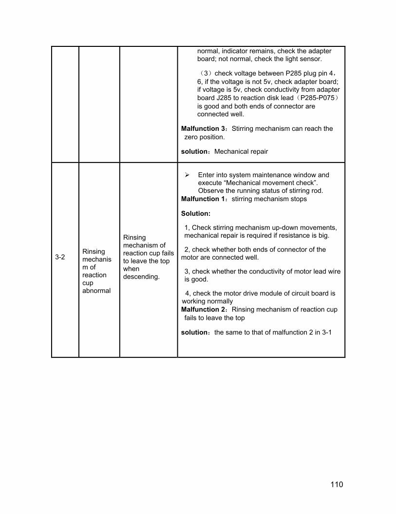
110
normal, indicator remains, check the adapter board; not normal, check the light sensor.
(3)check voltage between P285 plug pin 4,6, if the voltage is not 5v, check adapter board; if voltage is 5v, check conductivity from adapter board J285 to reaction disk lead(P285-P075)is good and both ends of connector are connected well.
Malfunction 3:Stirring mechanism can reach the zero position.
solution:Mechanical repair
3-2
Rinsing mechanism of reaction cup abnormal
Rinsing mechanism of reaction cup fails to leave the top when descending.
Enter into system maintenance window and
execute “Mechanical movement check”. Observe the running status of stirring rod.
Malfunction 1:stirring mechanism stops
Solution:
1, Check stirring mechanism up-down movements, mechanical repair is required if resistance is big.
2, check whether both ends of connector of the motor are connected well.
3, check whether the conductivity of motor lead wire is good.
4, check the motor drive module of circuit board is working normally Malfunction 2:Rinsing mechanism of reaction cup fails to leave the top
solution:the same to that of malfunction 2 in 3-1
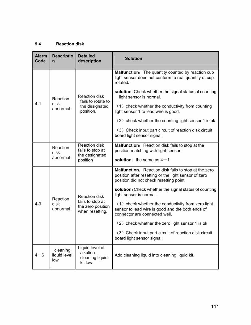
111
9.4 Reaction disk
Alarm Code
Description
Detailed description Solution
4-1 Reaction disk abnormal
Reaction disk fails to rotate to the designated position.
Malfunction:The quantity counted by reaction cup light sensor does not conform to real quantity of cup rotated.
solution:Check whether the signal status of counting light sensor is normal.
(1)check whether the conductivity from counting light sensor 1 to lead wire is good.
(2)check whether the counting light sensor 1 is ok.
(3)Check input part circuit of reaction disk circuit board light sensor signal.
Reaction disk abnormal
Reaction disk fails to stop at the designated position
Malfunction:Reaction disk fails to stop at the position matching with light sensor.
solution:the same as 4-1
4-3 Reaction disk abnormal
Reaction disk fails to stop at the zero position when resetting.
Malfunction:Reaction disk fails to stop at the zero position after resetting or the light sensor of zero position did not check resetting point.
solution:Check whether the signal status of counting light sensor is normal.
(1)check whether the conductivity from zero light sensor to lead wire is good and the both ends of connector are connected well.
(2)check whether the zero light sensor 1 is ok
(3)Check input part circuit of reaction disk circuit board light sensor signal.
4-6 cleaning
liquid level low
Liquid level of alkaline cleaning liquid kit low.
Add cleaning liquid into cleaning liquid kit.

112
9.5 Sample probe
Alarm Code Description Detailed
description Solution
5-1 Sample probe abnormal.
Sample probe fails to reach the top (except reaction cup side) after it rose.
Enter into system maintenance window and execute “Mechanical movement check”. Observe the running status of probe arm.
Malfunction 1:probe arm stops
Solution:
1, move probe mechanism, and mechanical repair is required if resistance is big.
2, check whether both ends of connector of the motor are connected well.
3, check whether the conductivity of motor lead wire is good.
4, check the circuit board of sample is working normally
Malfunction 2:Probe arm can rise to zero position.
Solution:Manually make sample probe mechanism repeatedly rise to peak, and observe ud_s adapter indicator status.
1、sparkling of ud_s indicator means the wiring of light sensor and adaptor are normal.
(1)check lead
Check whether the conductivity from adapter J282 to sample circuit board lead P282-P037 is good and both ends of connector are good.
(2) check sample circuit board
2、no sparkling of ud_s indicator, check ud_s
(1)check lead
Check whether the conductivity from adapter J281 to circuit board lead (P281-P411) is good and both
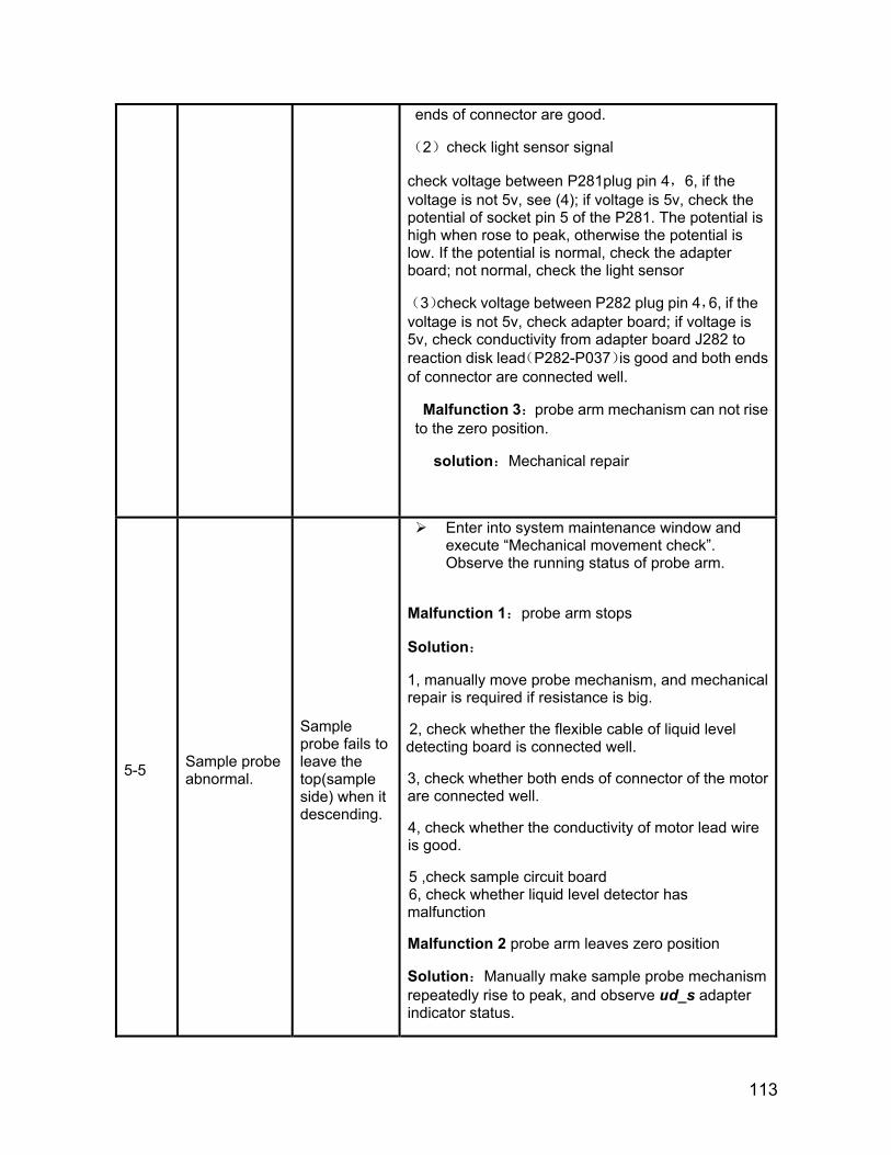
6, check whether liqui 5 ,check sample circuit board
113
ends of connector are good.
(2)check light sensor signal
check voltage between P281plug pin 4,6, if the voltage is not 5v, see (4); if voltage is 5v, check the potential of socket pin 5 of the P281. The potential is high when rose to peak, otherwise the potential is low. If the potential is normal, check the adapter board; not normal, check the light sensor
(3)check voltage between P282 plug pin 4,6, if the voltage is not 5v, check adapter board; if voltage is 5v, check conductivity from adapter board J282 to reaction disk lead(P282-P037)is good and both ends of connector are connected well.
Malfunction 3:probe arm mechanism can not rise to the zero position.
solution:Mechanical repair
5-5 Sample probe abnormal.
Sample probe fails to leave the top(sample side) when it descending.
Enter into system maintenance window and execute “Mechanical movement check”. Observe the running status of probe arm.
Malfunction 1:probe arm stops
Solution:
1, manually move probe mechanism, and mechanical repair is required if resistance is big.
2, check whether the flexible cable of liquid level detecting board is connected well.
3, check whether both ends of connector of the motor are connected well.
4, check whether the conductivity of motor lead wire is good.
d level detector has malfunction
Malfunction 2 probe arm leaves zero position
Solution:Manually make sample probe mechanism repeatedly rise to peak, and observe ud_s adapter indicator status.

114
1、sparkling of ud_s indicator means the wiring of light sensor , lead and adaptor is normal.
(1)check lead
Check whether the conductivity from adapter J282 to sample circuit board lead P282-P037 is good and both ends of connector are good.
(2) check sample circuit board
2. if no sparkling of ud_s indicator, check ud_s
(1)check lead
Check whether the conductivity from adapter J281 to circuit board lead (P281-P411) is good and both ends of connector are good.
(2)check light sensor signal
check voltage between P281plug pin 4,6, if the voltage is not 5v, see (3); if voltage is 5v, check the potential of socket pin 5 of the P281. The potential is high when light sensor is sheltered, otherwise the potential is low. If the potential is normal, check the adapter board; not normal, check the light sensor
(3)check voltage between P282 plug pin 4,6, if the voltage is not 5v, check adapter board; if voltage is 5v, check conductivity from adapter board J282 to reaction disk lead(P282-P037)is good and both ends of connector are connected well.
5-6 Sample probe abnormal.
Sample probe fails to leave the top (reaction cup side) when it descending.
The solution is as same as 5-5
5-7 Sample probe abnormal.
Sample probe stays in a valid status of touching or liquid level detecting.
Malfunction:Sample probe stays in a valid status of touching or liquid level detecting.
Solution:Sample probe stops .Observe the indicator status when raising probe(Analog touch) manually and repeatedly and touch probe point (Analog liquid level detection)repeatedly.
Initial status:surface_s、touch_s : the touch when it is bright; touch_s : put out;liquid level detection:
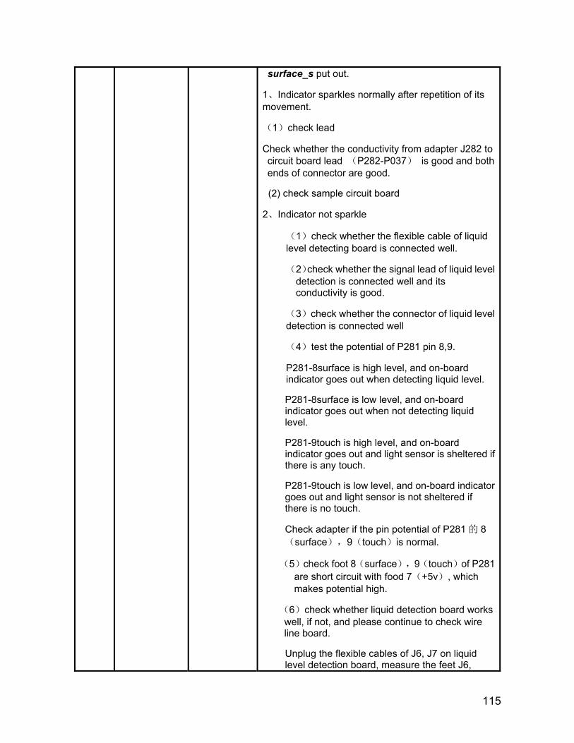
115
surface_s put out.
1、Indicator sparkles normally after repetition of its movement.
(1)check lead
Check whether the conductivity from adapter J282 to circuit board lead (P282-P037) is good and both ends of connector are good.
(2) check sample circuit board
2、Indicator not sparkle
(1)check whether the flexible cable of liquid level detecting board is connected well.
(2)check whether the signal lead of liquid level detection is connected well and its conductivity is good.
(3)check whether the connector of liquid level detection is connected well
(4)test the potential of P281 pin 8,9.
P281-8surface is high level, and on-board indicator goes out when detecting liquid level.
P281-8surface is low level, and on-board indicator goes out when not detecting liquid level.
P281-9touch is high level, and on-board indicator goes out and light sensor is sheltered if there is any touch.
P281-9touch is low level, and on-board indicator goes out and light sensor is not sheltered if there is no touch.
Check adapter if the pin potential of P281 的 8(surface),9(touch)is normal.
(5)check foot 8(surface),9(touch)of P281 are short circuit with food 7(+5v), which makes potential high.
(6)check whether liquid detection board works well, if not, and please continue to check wire line board.
Unplug the flexible cables of J6, J7 on liquid level detection board, measure the feet J6,
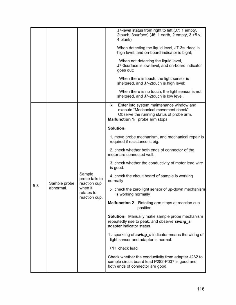
116
J7-level status from right to left (J7: 1 empty, 2touch, 3surface) (J6: 1 earth, 2 empty, 3 +5 v, 4 blank)
When detecting the liquid level, J7-3surface is high level, and on-board indicator is bight;
When not detecting the liquid level, J7-3surface is low level, and on-board indicator goes out;
When there is touch, the light sensor is sheltered, and J7-2touch is high level;
When there is no touch, the light sensor is not sheltered, and J7-2touch is low level.
5-8 Sample probe abnormal.
Sample probe fails to reaction cup when it rotates to reaction cup.
Enter into system maintenance window and execute “Mechanical movement check”. Observe the running status of probe arm.
Malfunction 1:probe arm stops
Solution:
1, move probe mechanism, and mechanical repair is required if resistance is big.
2, check whether both ends of connector of the motor are connected well.
3, check whether the conductivity of motor lead wire is good.
4, check the circuit board of sample is working normally
5、check the zero light sensor of up-down mechanism is working normally
Malfunction 2:Rotating arm stops at reaction cup position.
Solution:Manually make sample probe mechanism repeatedly rise to peak, and observe swing_s adapter indicator status.
1、sparkling of swing_s indicator means the wiring of light sensor and adaptor is normal.
(1)check lead
Check whether the conductivity from adapter J282 to sample circuit board lead P282-P037 is good and both ends of connector are good.
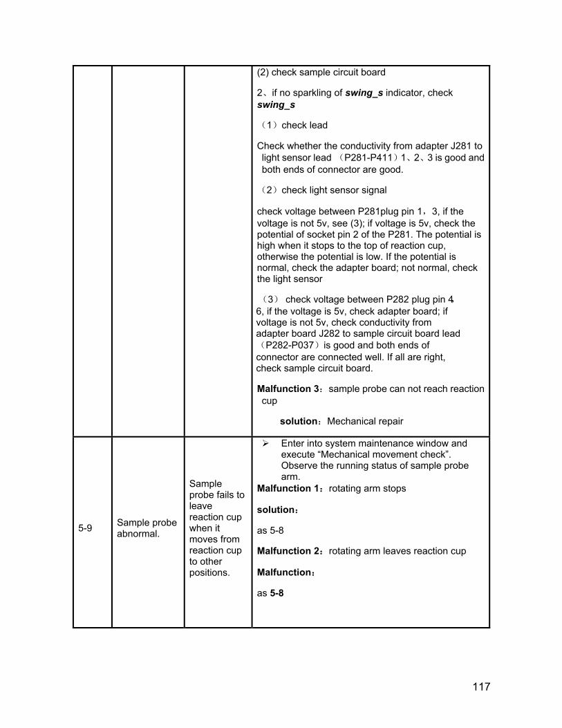
117
(2) check sample circuit board
2、if no sparkling of swing_s indicator, check swing_s
(1)check lead
Check whether the conductivity from adapter J281 to light sensor lead (P281-P411)1、2、3 is good and both ends of connector are good.
(2)check light sensor signal
check voltage between P281plug pin 1,3, if the voltage is not 5v, see (3); if voltage is 5v, check the potential of socket pin 2 of the P281. The potential is high when it stops to the top of reaction cup, otherwise the potential is low. If the potential is normal, check the adapter board; not normal, check the light sensor
(3) check voltage between P282 plug pin 4,6, if the voltage is 5v, check adapter board; if voltage is not 5v, check conductivity from adapter board J282 to sample circuit board lead(P282-P037)is good and both ends of connector are connected well. If all are right, check sample circuit board.
Malfunction 3:sample probe can not reach reaction cup
solution:Mechanical repair
5-9 Sample probe abnormal.
Sample probe fails to leave reaction cup when it moves from reaction cup to other positions.
Enter into system maintenance window and execute “Mechanical movement check”. Observe the running status of sample probe arm.
Malfunction 1:rotating arm stops
solution:
as 5-8
Malfunction 2:rotating arm leaves reaction cup
Malfunction:
as 5-8
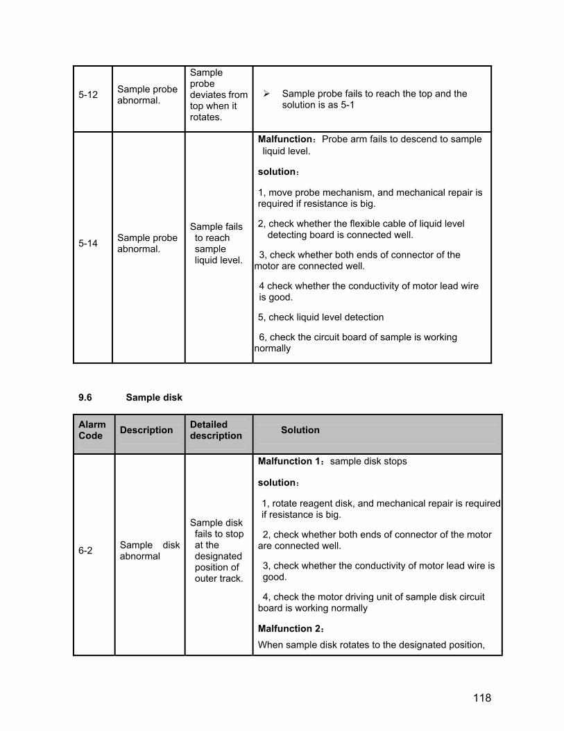
118
5-12 Sample probe abnormal.
Sample probe deviates from top when it rotates.
Sample probe fails to reach the top and the solution is as 5-1
5-14 Sample probe abnormal.
Sample fails to reach sample liquid level.
Malfunction:Probe arm fails to descend to sample liquid level.
solution:
1, move probe mechanism, and mechanical repair is required if resistance is big.
2, check whether the flexible cable of liquid level detecting board is connected well.
3, check whether both ends of connector of the motor are connected well.
4 check whether the conductivity of motor lead wire is good.
5, check liquid level detection
6, check the circuit board of sample is working normally
9.6 Sample disk
Alarm Code Description Detailed
description Solution
6-2 Sample disk abnormal
Sample disk fails to stop at the designated position of outer track.
Malfunction 1:sample disk stops
solution:
1, rotate reagent disk, and mechanical repair is required if resistance is big.
2, check whether both ends of connector of the motor are connected well.
3, check whether the conductivity of motor lead wire is good.
4, check the motor driving unit of sample disk circuit board is working normally
Malfunction 2:
When sample disk rotates to the designated position,
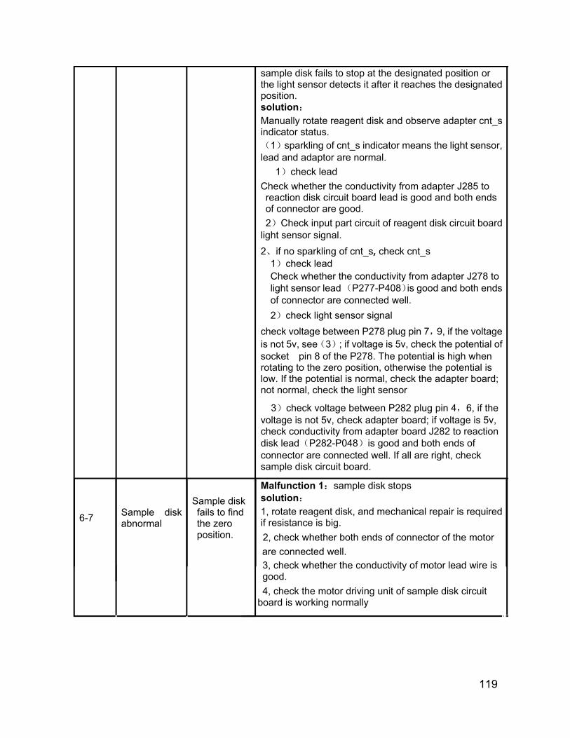
119
sample disk fails to stop at the designated position or the light sensor detects it after it reaches the designated position. solution:
Manually rotate reagent disk and observe adapter cnt_s indicator status. (1)sparkling of cnt_s
indicator means the light sensor, lead and adaptor are normal.
1)check lead
Check whether the conductivity from adapter J285 to reaction disk circuit board lead is good and both ends of connector are good.
2)Check input part circuit of reagent disk circuit board light sensor signal. 2、if no sparkling of cnt_s, check cnt_s
1)check lead Check whether the conductivity from adapter J278 to light sensor lead (P277-P408)is good and both ends of connector are connected well. 2)check light sensor signal
check voltage between P278 plug pin 7,9, if the voltage is not 5v, see(3); if voltage is 5v, check the potential of socket pin 8 of the P278. The potential is high when rotating to the zero position, otherwise the potential is low. If the potential is normal, check the adapter board; not normal, check the light sensor
3)check voltage between P282 plug pin 4,6, if the voltage is not 5v, check adapter board; if voltage is 5v, check conductivity from adapter board J282 to reaction disk lead(P282-P048)is good and both ends of connector are connected well. If all are right, check sample disk circuit board.
6-7 Sample disk abnormal
Sample disk fails to find the zero position.
Malfunction 1:sample disk stops solution:
1, rotate reagent disk, and mechanical repair is required if resistance is big.
2, check whether both ends of connector of the motor are connected well.
3, check whether the conductivity of motor lead wire is good.
4, check the motor driving unit of sample disk circuit board is working normally
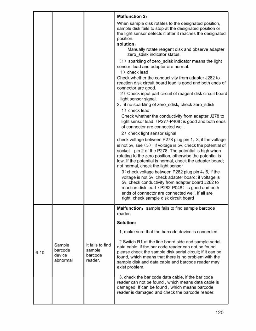
120
Malfunction 2:
When sample disk rotates to the designated position, sample disk fails to stop at the designated position or the light sensor detects it after it reaches the designated position. solution:
Manually rotate reagent disk and observe adapter zero_sdisk indicator status.
(1)sparkling of zero_sdisk
indicator means the light sensor, lead and adaptor are normal.
1)check lead Check whether the conductivity from adapter J282 to reaction disk circuit board lead is good and both ends of connector are good.
2)Check input part circuit of reagent disk circuit board light sensor signal.
2、if no sparkling of zero_sdisk, check zero_sdisk 1)check lead Check whether the conductivity from adapter J278 to light sensor lead (P277-P408)is good and both ends of connector are connected well. 2)check light sensor signal
check voltage between P278 plug pin 1,3, if the voltage is not 5v, see(3); if voltage is 5v, check the potential of socket pin 2 of the P278. The potential is high when rotating to the zero position, otherwise the potential is low. If the potential is normal, check the adapter board; not normal, check the light sensor
3)check voltage between P282 plug pin 4,6, if the voltage is not 5v, check adapter board; if voltage is 5v, check conductivity from adapter board J282 to reaction disk lead(P282-P048)is good and both ends of connector are connected well. If all are right, check sample disk circuit board
6-10
Sample barcode device abnormal
It fails to find sample barcode reader.
Malfunction:sample fails to find sample barcode reader.
Solution:
1, make sure that the barcode device is connected.
2 Switch R1 at the line board side and sample serial data cable, if the bar code reader can not be found, please check the sample disk serial circuit; if it can be found, which means that there is no problem with the sample disk and data cable and barcode reader may exist problem.
3, check the bar code data cable, if the bar code reader can not be found , which means data cable is damaged; If can be found , which means barcode reader is damaged and check the barcode reader.

121
9.7 Sample injection pump
Alarm Code Description Detailed
description Solution
7-1 Sample injection pump abnormal
Sample injection pump fails to reach the top
Malfunction 1:the pump stops or can not reach the top
solution:
Observe the sample pump running status:
1, When working, the sample pump is not running:
(1) Check whether both ends of connector of the motor are connected well.
(2) Check whether the conductivity of motor lead wire is good.
(3) check the motor drive circuit of circuit board
2、When working, the sample pump is running:
(1) check whether light sensor is good
(2) Check whether the conductivity of light sensor from adapter, reaction disk circuit board lead is good and both ends of connector are good.
(3) check light sensor signal
check voltage between P274 plug pin 1,3, if the voltage is not 5v, see(3); If voltage is 5v, check the potential of socket pin 2 of the P274. The potential is high when the pump reaches the zero position (discharging liquid), otherwise the potential is low. If the potential is normal, check the adapter board; not normal, check the light sensor
(4)check voltage between P282 plug pin 4,6, if the voltage is not 5v, check adapter board; if voltage is 5v, check conductivity from adapter board J282 to reaction disk lead(P282-P037)is good and both ends of connector are connected well. If all are right, check input part

122
circuit of sample disk circuit board
7-2 Sample injection pump abnormal
Sample injection pump fails to leave the top
Malfunction 1:the pump stops or fails to leave the top
Observe the sample pump running status:
1, When working, the motor is not running:
(1) Check whether both ends of connector of the motor are connected well.
(2) Check whether the conductivity of motor lead wire is good.
(3) check the motor drive circuit of circuit board
2、When working, the motor is running:
(1) check whether light sensor is good
(2) Check whether the conductivity of light sensor from adapter, reaction disk circuit board lead is good and both ends of connector are good.
(3) check light sensor signal
3. check light sensor signal
check voltage between P274 plug pin 1,3, if the voltage is not 5v, see(3); If voltage is 5v, check the potential of socket pin 2 of the P274. The potential is high when the pump reaches the zero position (discharging liquid), otherwise the potential is low. If the potential is normal, check the adapter board; not normal, check the light sensor
4. check voltage between P282 plug pin 4,6, if the voltage is not 5v, check adapter board; if voltage is 5v, check conductivity from adapter board J282 to reaction disk lead(P282-P037)is good and both ends of connector are connected well. If all are right, check input part circuit of sample disk circuit board
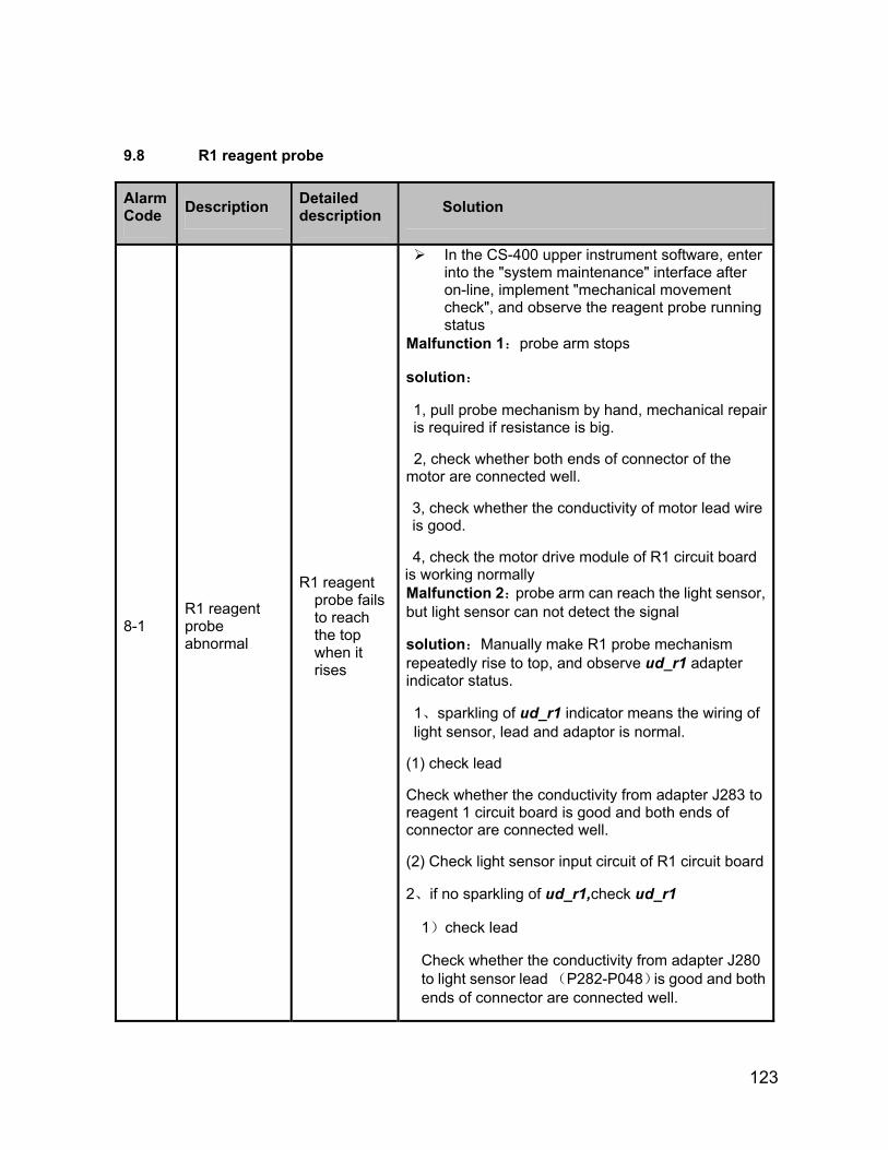
123
9.8 R1 reagent probe
Alarm Code Description Detailed
description Solution
8-1 R1 reagent probe abnormal
R1 reagent probe fails to reach the top when it rises
In the CS-400 upper instrument software, enter into the "system maintenance" interface after on-line, implement "mechanical movement check", and observe the reagent probe running status
Malfunction 1:probe arm stops
solution:
1, pull probe mechanism by hand, mechanical repair is required if resistance is big.
2, check whether both ends of connector of the motor are connected well.
3, check whether the conductivity of motor lead wire is good.
4, check the motor drive module of R1 circuit board is working normally Malfunction 2:probe arm can reach the light sensor, but light sensor can not detect the signal
solution:Manually make R1 probe mechanism repeatedly rise to top, and observe ud_r1 adapter indicator status.
1、sparkling of ud_r1 indicator means the wiring of light sensor, lead and adaptor is normal.
(1) check lead
Check whether the conductivity from adapter J283 to reagent 1 circuit board is good and both ends of connector are connected well.
(2) Check light sensor input circuit of R1 circuit board
2、if no sparkling of ud_r1,check ud_r1
1)check lead
Check whether the conductivity from adapter J280 to light sensor lead (P282-P048)is good and both ends of connector are connected well.
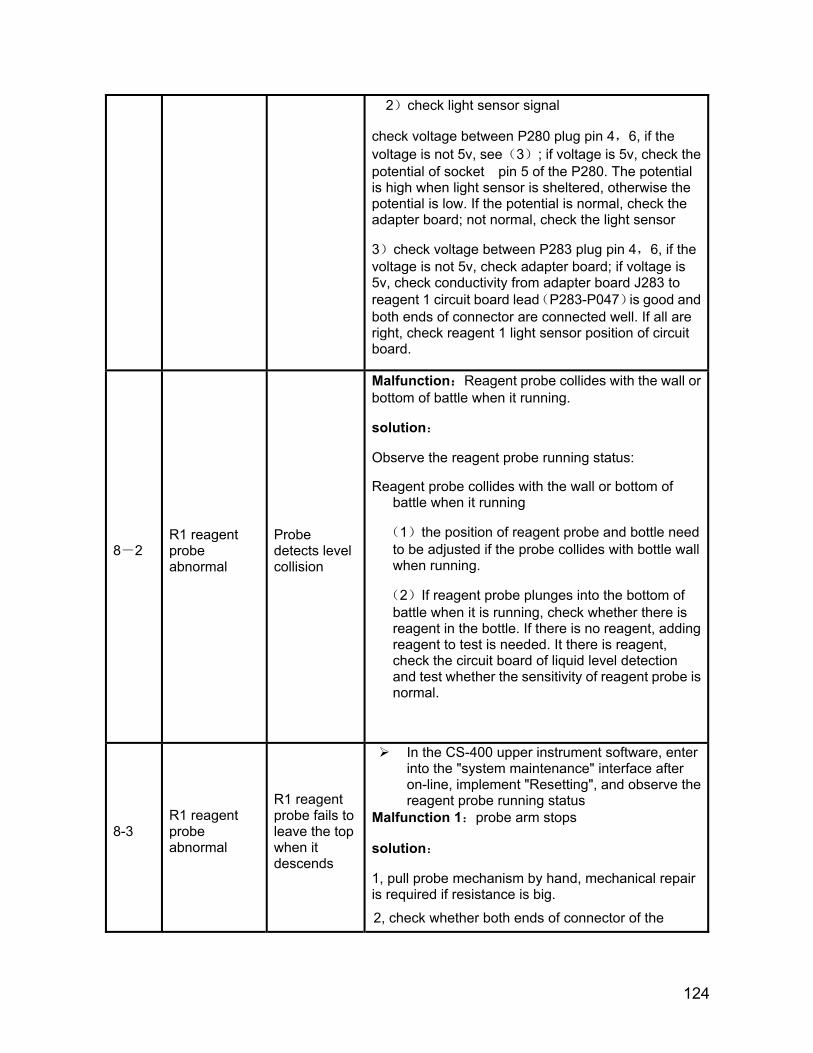
124
2)check light sensor signal
check voltage between P280 plug pin 4,6, if the voltage is not 5v, see(3); if voltage is 5v, check the potential of socket pin 5 of the P280. The potential is high when light sensor is sheltered, otherwise the potential is low. If the potential is normal, check the adapter board; not normal, check the light sensor
3)check voltage between P283 plug pin 4,6, if the voltage is not 5v, check adapter board; if voltage is 5v, check conductivity from adapter board J283 to reagent 1 circuit board lead(P283-P047)is good and both ends of connector are connected well. If all are right, check reagent 1 light sensor position of circuit board.
8-2 R1 reagent probe abnormal
Probe detects level collision
Malfunction:Reagent probe collides with the wall or bottom of battle when it running.
solution:
Observe the reagent probe running status:
Reagent probe collides with the wall or bottom of battle when it running
(1)the position of reagent probe and bottle need to be adjusted if the probe collides with bottle wall when running.
(2)If reagent probe plunges into the bottom of battle when it is running, check whether there is reagent in the bottle. If there is no reagent, adding reagent to test is needed. It there is reagent, check the circuit board of liquid level detection and test whether the sensitivity of reagent probe is normal.
8-3 R1 reagent probe abnormal
R1 reagent probe fails to leave the top when it descends
In the CS-400 upper instrument software, enter into the "system maintenance" interface after on-line, implement "Resetting", and observe the reagent probe running status
Malfunction 1:probe arm stops
solution:
1, pull probe mechanism by hand, mechanical repair is required if resistance is big.
2, check whether both ends of connector of the

125
motor are connected well.
3, check whether the conductivity of motor lead wire is good.
4, check the motor drive module of R1 circuit board is working normally
Malfunction 2:probe arm can reach the light sensor, but light sensor can not detect the signal
solution:Manually make R1 probe mechanism repeatedly rise to top, and observe ud_r1 adapter indicator status.
1、sparkling of ud_r1 indicator means the light sensor, lead and adaptor are normal.
(1) check lead
Check whether the conductivity from adapter J283 to reagent 1circuit board (P283-P047)is good and both ends of connector are connected well.
(2) Check light sensor input circuit of R1 circuit board
2、if no sparkling of ud_r1,check ud_r1
1)check lead
Check whether the conductivity from adapter J280 to light sensor lead (P282-P048)is good and both ends of connector are connected well.
2)check light sensor signal
check voltage between P280 plug pin 4,6, if the voltage is not 5v, see(3); if voltage is 5v, check the potential of socket pin 5 of the P280. The potential is high when light sensor is sheltered, otherwise the potential is low. If the potential is normal, check the adapter board; not normal, check the light sensor
3)check voltage between P283 plug pin 4,6, if the voltage is not 5v, check adapter board; if voltage is 5v, check conductivity from adapter board J283 to reagent 1 circuit board lead(P283-P047)is good and both ends of connector are connected well. If all are right, check reagent 1 light sensor position of circuit board
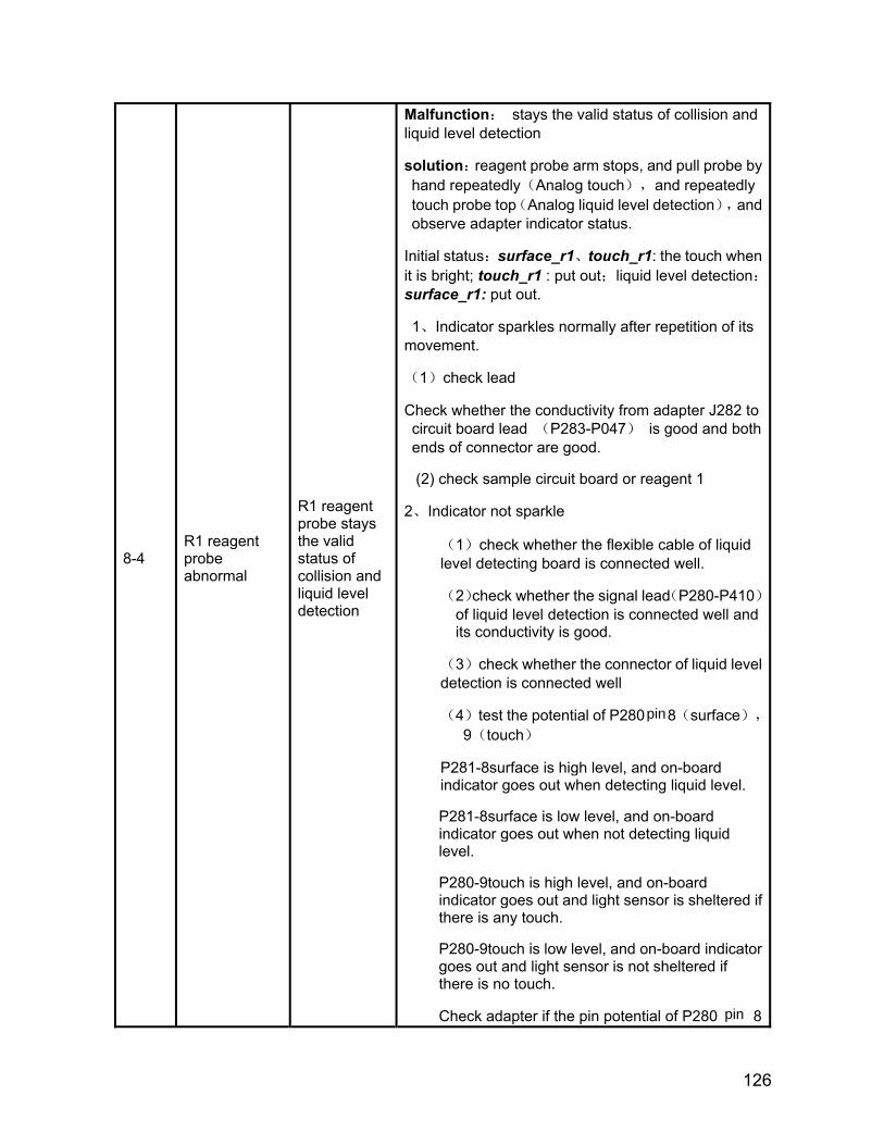
126
8-4 R1 reagent probe abnormal
R1 reagent probe stays the valid status of collision and liquid level detection
Malfunction: stays the valid status of collision and liquid level detection
solution:reagent probe arm stops, and pull probe by hand repeatedly(Analog touch),and repeatedly touch probe top(Analog liquid level detection),and observe adapter indicator status.
Initial status:surface_r1、touch_r1: the touch when it is bright; touch_r1 : put out;liquid level detection:surface_r1: put out.
1、Indicator sparkles normally after repetition of its movement.
(1)check lead
Check whether the conductivity from adapter J282 to circuit board lead (P283-P047) is good and both ends of connector are good.
(2) check sample circuit board or reagent 1
2、Indicator not sparkle
(1)check whether the flexible cable of liquid level detecting board is connected well.
(2)check whether the signal lead(P280-P410)of liquid level detection is connected well and its conductivity is good.
(3)check whether the connector of liquid level detection is connected well
(4)test the potential of P280 8(surface),
9(touch)
P281-8surface is high level, and on-board indicator goes out when detecting liquid level.
P281-8surface is low level, and on-board indicator goes out when not detecting liquid level.
P280-9touch is high level, and on-board indicator goes out and light sensor is sheltered if there is any touch.
P280-9touch is low level, and on-board indicator goes out and light sensor is not sheltered if there is no touch.
Check adapter if the pin potential of P280 8
pin
pin
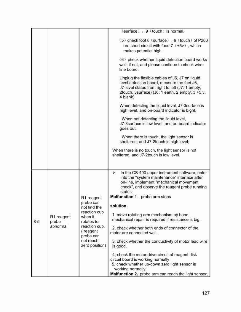
127
(surface),9(touch)is normal.
(5)check foot 8(surface),9(touch)of P280 are short circuit with food 7(+5v), which makes potential high.
(6)check whether liquid detection board works well, if not, and please continue to check wire line board.
Unplug the flexible cables of J6, J7 on liquid level detection board, measure the feet J6, J7-level status from right to left (J7: 1 empty, 2touch, 3surface) (J6: 1 earth, 2 empty, 3 +5 v, 4 blank)
When detecting the liquid level, J7-3surface is high level, and on-board indicator is bight;
When not detecting the liquid level, J7-3surface is low level, and on-board indicator goes out;
When there is touch, the light sensor is sheltered, and J7-2touch is high level;
When there is no touch, the light sensor is not sheltered, and J7-2touch is low level.
8-5 R1 reagent probe abnormal
R1 reagent probe can not find the reaction cup when it rotates to reaction cup. ( reagent probe can not reach zero position)
In the CS-400 upper instrument software, enter into the "system maintenance" interface after on-line, implement "mechanical movement check", and observe the reagent probe running status
Malfunction 1:probe arm stops
solution:
1, move rotating arm mechanism by hand, mechanical repair is required if resistance is big.
2, check whether both ends of connector of the motor are connected well.
3, check whether the conductivity of motor lead wire is good.
4, check the motor drive circuit of reagent disk circuit board is working normally 5, check whether up-down zero light sensor is
working normally. Malfunction 2:probe arm can reach the light sensor,
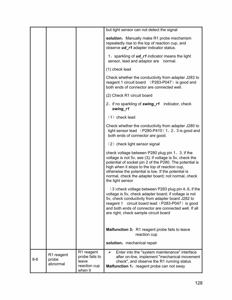
128
but light sensor can not detect the signal
solution:Manually make R1 probe mechanism repeatedly rise to the top of reaction cup, and observe ud_r1 adapter indicator status.
1、sparkling of ud_r1 indicator means the light sensor, lead and adaptor are normal.
(1) check lead
Check whether the conductivity from adapter J283 to reagent 1 circuit board (P283-P047)is good and both ends of connector are connected well.
(2) Check R1 circuit board
2、if no sparkling of swing_r1 indicator, check swing_r1
(1)check lead
Check whether the conductivity from adapter J280 to light sensor lead (P280-P410)1、2、3 is good and both ends of connector are good.
(2)check light sensor signal
check voltage between P280 plug pin 1,3, if the voltage is not 5v, see (3); if voltage is 5v, check the potential of socket pin 2 of the P280. The potential is high when it stops to the top of reaction cup, otherwise the potential is low. If the potential is normal, check the adapter board; not normal, check the light sensor
(3)check voltage between P283 plug pin 4,6, if the voltage is 5v, check adapter board; if voltage is not 5v, check conductivity from adapter board J282 to reagent 1 circuit board lead(P283-P047)is good and both ends of connector are connected well. If all are right, check sample circuit board
Malfunction 3:R1 reagent probe fails to leave reaction cup
solution:mechanical repair
8-6 R1 reagent probe abnormal
R1 reagent probe fails to leave reaction cup when it
Enter into the "system maintenance" interface after on-line, implement "mechanical movement check", and observe the R1 running status
Malfunction 1:reagent probe can not sway

129
rotates from reaction cup
solution:As 8-5
Malfunction 2:rotating arm can leave reaction cup, but light sensor can not detect the signal
solution:As 8-5
8-7 R1 reagent probe abnormal
R1 reagent probe deflects when rotating
Probe fails to reach the top and solution is the same as 8-1
8-8 R1 reagent probe abnormal
Liquid level is not detected at R1 reagent position
Malfunction:Reagent probe does not detect when reagent bottle has liquid.
solution:
1、check whether the wiring conductivity of liquid level detection board and reagent circuit board is good, and both ends of connector is connected well.
2、check the circuit board of liquid level detection and test whether the sensitivity of reagent probe is normal
3、check input circuit of reagent circuit board signal
8-9 R1 reagent probe abnormal
R1 reagent probe fails to reach liquid level when it descends
Malfunction:R1 reagent probe fails to reach liquid level when it descends
solution
1, move probe mechanism by hand, mechanical repair is required if resistance is big.
2, check whether the flexible cable of liquid level detecting board is connected well.
3. check whether both ends of connector of the motor are connected well.
4. check whether the conductivity of motor lead wire is good.
5, check the liquid level detection 6. check reagent 1 circuit board
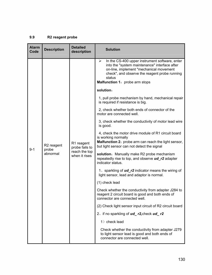
130
9.9 R2 reagent probe
Alarm Code Description Detailed
description Solution
9-1 R2 reagent probe abnormal
R1 reagent probe fails to reach the top when it rises
In the CS-400 upper instrument software, enter into the "system maintenance" interface after on-line, implement "mechanical movement check", and observe the reagent probe running status
Malfunction 1:probe arm stops
solution:
1, pull probe mechanism by hand, mechanical repair is required if resistance is big.
2, check whether both ends of connector of the motor are connected well.
3, check whether the conductivity of motor lead wire is good.
4, check the motor drive module of R1 circuit board is working normally Malfunction 2:probe arm can reach the light sensor, but light sensor can not detect the signal
solution:Manually make R2 probe mechanism repeatedly rise to top, and observe ud_r2 adapter indicator status.
1、sparkling of ud_r2 indicator means the wiring of light sensor, lead and adaptor is normal.
(1) check lead
Check whether the conductivity from adapter J284 to reagent 2 circuit board is good and both ends of connector are connected well.
(2) Check light sensor input circuit of R2 circuit board
2、if no sparkling of ud_ r2,check ud_ r2
1)check lead
Check whether the conductivity from adapter J279 to light sensor lead is good and both ends of connector are connected well.
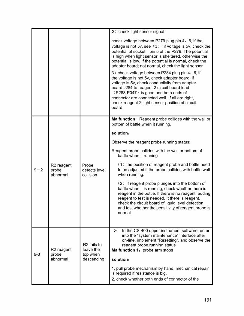
descending
131
2)check light sensor signal
check voltage between P279 plug pin 4,6, if the voltage is not 5v, see(3); if voltage is 5v, check the potential of socket pin 5 of the P279. The potential is high when light sensor is sheltered, otherwise the potential is low. If the potential is normal, check the adapter board; not normal, check the light sensor 3)check voltage between P284 plug pin 4,6, if the voltage is not 5v, check adapter board; if voltage is 5v, check conductivity from adapter board J284 to reagent 2 circuit board lead(P283-P047)is good and both ends of connector are connected well. If all are right, check reagent 2 light sensor position of circuit board.
9-2 R2 reagent probe abnormal
Probe detects level collision
Malfunction:Reagent probe collides with the wall or bottom of battle when it running.
solution:
Observe the reagent probe running status:
Reagent probe collides with the wall or bottom of battle when it running
(1)the position of reagent probe and bottle need to be adjusted if the probe collides with bottle wall when running.
(2)If reagent probe plunges into the bottom of battle when it is running, check whether there is reagent in the bottle. If there is no reagent, adding reagent to test is needed. It there is reagent, check the circuit board of liquid level detection and test whether the sensitivity of reagent probe is normal.
9-3 R2 reagent probe abnormal
R2 fails to leave the top when
In the CS-400 upper instrument software, enter into the "system maintenance" interface after on-line, implement "Resetting", and observe the reagent probe running status
Malfunction 1:probe arm stops
solution:
1, pull probe mechanism by hand, mechanical repair is required if resistance is big.
2, check whether both ends of connector of the
132
motor are connected well.
3, check whether the conductivity of motor lead wire is good.
4, check the motor drive module of R1 circuit board is working normally
Malfunction 2:probe arm can reach the light sensor, but light sensor can not detect the signal
solution:Manually make R1 probe mechanism repeatedly rise to top, and observe ud_ r2 adapter indicator status.
1、sparkling of ud_ r2 indicator means the light sensor, lead and adaptor are normal.
(1) check lead
Check whether the conductivity from adapter J284 to reagent 2 circuit board is good and both ends of connector are connected well.
(2) Check light sensor input circuit of R1 circuit board
2、if no sparkling of ud_ r2,check ud_ r2
1)check lead
Check whether the conductivity from adapter J279 to light sensor lead (P280-P410) is good and both ends of connector are connected well.
2)check light sensor signal
check voltage between P279 plug pin 4,6, if the voltage is not 5v, see(3); if voltage is 5v, check the potential of socket pin 5 of the P279. The potential is high when light sensor is sheltered, otherwise the potential is low. If the potential is normal, check the adapter board; not normal, check the light sensor
3)check voltage between P284 plug pin 4,6, if the voltage is not 5v, check adapter board; if voltage is 5v, check conductivity from adapter board J284 to reagent 2 circuit board lead is good and both ends of connector are connected well. If all are right, check reagent 2 light sensor position of circuit board
133
9-4 R2 reagent probe abnormal
R2 reagent probe stays the valid status of collision and liquid level detection
Malfunction: stays the valid status of collision and liquid level detection
solution:reagent probe arm stops, and pull probe by hand repeatedly(Analog touch),and repeatedly touch probe top(Analog liquid level detection),and observe adapter indicator status.
Initial status:surface_r2、touch_r2: the touch when it is bright; touch_ r2: put out;liquid level detection:surface_ r2: put out.
1、Indicator sparkles normally after repetition of its movement.
(1)check lead
Check whether the conductivity from adapter J284 to reagent 2 circuit board lead is good and both ends of connector are good.
(2) check sample circuit board or reagent 2
2、Indicator not sparkles
(1)check whether the flexible cable of liquid level detecting board is connected well.
(2)check whether the signal lead of liquid level detection is connected well and its conductivity is good.
(3)check whether the connector of liquid level detection is connected well
(4)test the potential of P279 8(surface),9(touch)
P279-8surface is high level, and on-board indicator goes out when detecting liquid level.
P279-8surface is low level, and on-board indicator goes out when not detecting liquid level.
P279-9touch is high level, and on-board indicator goes out and light sensor is sheltered if there is any touch.
P279-9touch is low level, and on-board indicator goes out and light sensor is not sheltered if there is no touch.
Check adapter if the pin potential of P279 8pin
134
(surface),9(touch)is normal.
(5)check foot 8(surface),9(touch)of P280 are short circuit with food 7(+5v), which makes potential high.
(6)check whether liquid detection board works well, if not, and please continue to check wire line board.
Unplug the flexible cables of J6, J7 on liquid level detection board, measure the feet J6, J7-level status from right to left (J7: 1 empty, 2touch, 3surface) (J6: 1 earth, 2 empty, 3 +5 v, 4 blank)
When detecting the liquid level, J7-3surface is high level, and on-board indicator is bright;
When not detecting the liquid level, J7-3surface is low level, and on-board indicator goes out;
When there is touch, the light sensor is sheltered, and J7-2touch is high level;
When there is no touch, the light sensor is not sheltered, and J7-2touch is low level.
9-5 R2 reagent probe abnormal
R2 reagent probe can not find the reaction cup when it rotates to reaction cup. ( reagent probe can not reach zero position)
In the CS-400 upper instrument software, enter into the "system maintenance" interface after on-line, implement "mechanical movement check", and observe the reagent probe running status
Malfunction 1:probe arm stops
solution:
1, move rotating arm mechanism by hand, mechanical repair is required if resistance is big.
2, check whether both ends of connector of the motor are connected well.
3, check whether the conductivity of motor lead wire is good.
4, check the motor drive circuit of reagent disk circuit board is working normally 5, check whether up-down zero light sensor is working normally.
Malfunction 2:probe arm can reach the light sensor,
135
but light sensor can not detect the signal
solution:Manually make R1 probe mechanism repeatedly rise to the top of reaction cup, and observe ud_ r2 adapter indicator status.
1、sparkling of ud_ r2 indicator means the light sensor, lead and adaptor are normal.
(1) check lead
Check whether the conductivity from adapter J284 to reagent 1 circuit board is good and both ends of connector are connected well.
(2) Check R1 circuit board
2、if no sparkling of swing_ r2 indicator, check swing_ r2
(1)check lead
Check whether the conductivity from adapter J279 to light sensor leads 1、2、3 is good and both ends of connector are good.
(2)check light sensor signal
check voltage between P280 plug pin 1,3, if the voltage is not 5v, see (3); if voltage is 5v, check the potential of socket pin 2 of the P280. The potential is high when it stops to the top of reaction cup, otherwise the potential is low. If the potential is normal, check the adapter board; not normal, check the light sensor
(3)check voltage between P284 plug pin 4,6, if the voltage is 5v, check adapter board; if voltage is not 5v, check conductivity from adapter board P284 to reagent 1 circuit board lead is good and both ends of connector are connected well. If all are right, check sample circuit board
Malfunction 3:R2 reagent probe fails to leave reaction cup
solution:mechanical repair
9-6 R21 reagent probe abnormal
R2 reagent probe fails to leave reaction cup when it
Enter into the "system maintenance" interface after on-line, implement "mechanical movement check", and observe the reagent probe running status
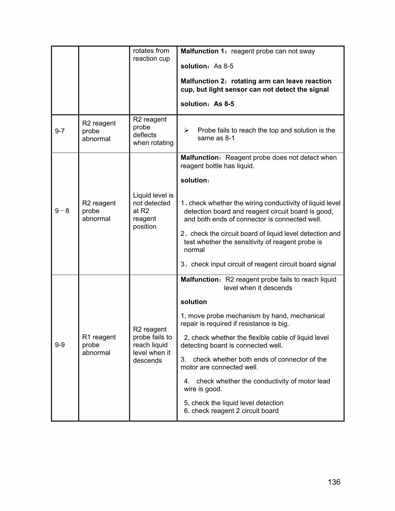
136
rotates from reaction cup
Malfunction 1:reagent probe can not sway
solution:As 8-5
Malfunction 2:rotating arm can leave reaction cup, but light sensor can not detect the signal
solution:As 8-5
9-7 R2 reagent probe abnormal
R2 reagent probe deflects when rotating
Probe fails to reach the top and solution is the same as 8-1
9-8 R2 reagent probe abnormal
Liquid level is not detected at R2 reagent position
Malfunction:Reagent probe does not detect when reagent bottle has liquid.
solution:
1、check whether the wiring conductivity of liquid level detection board and reagent circuit board is good, and both ends of connector is connected well.
2、check the circuit board of liquid level detection and test whether the sensitivity of reagent probe is normal
3、check input circuit of reagent circuit board signal
9-9 R1 reagent probe abnormal
R2 reagent probe fails to reach liquid level when it descends
Malfunction:R2 reagent probe fails to reach liquid level when it descends
solution
1, move probe mechanism by hand, mechanical repair is required if resistance is big.
2, check whether the flexible cable of liquid level detecting board is connected well.
3. check whether both ends of connector of the motor are connected well.
4. check whether the conductivity of motor lead wire is good.
5, check the liquid level detection 6. check reagent 2 circuit board
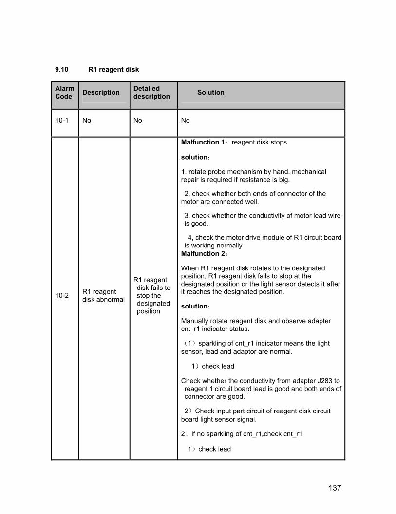
137
9.10 R1 reagent disk
Alarm Code Description Detailed
description Solution
10-1 No No No
10-2 R1 reagent disk abnormal
R1 reagent disk fails to stop the designated position
Malfunction 1:reagent disk stops
solution:
1, rotate probe mechanism by hand, mechanical repair is required if resistance is big.
2, check whether both ends of connector of the motor are connected well.
3, check whether the conductivity of motor lead wire is good.
4, check the motor drive module of R1 circuit board is working normally
Malfunction 2:
When R1 reagent disk rotates to the designated position, R1 reagent disk fails to stop at the designated position or the light sensor detects it after it reaches the designated position.
solution:
Manually rotate reagent disk and observe adapter cnt_r1 indicator status.
(1)sparkling of cnt_r1 indicator means the light sensor, lead and adaptor are normal.
1)check lead
Check whether the conductivity from adapter J283 to reagent 1 circuit board lead is good and both ends of connector are good.
2)Check input part circuit of reagent disk circuit board light sensor signal.
2、if no sparkling of cnt_r1,check cnt_r1
1)check lead
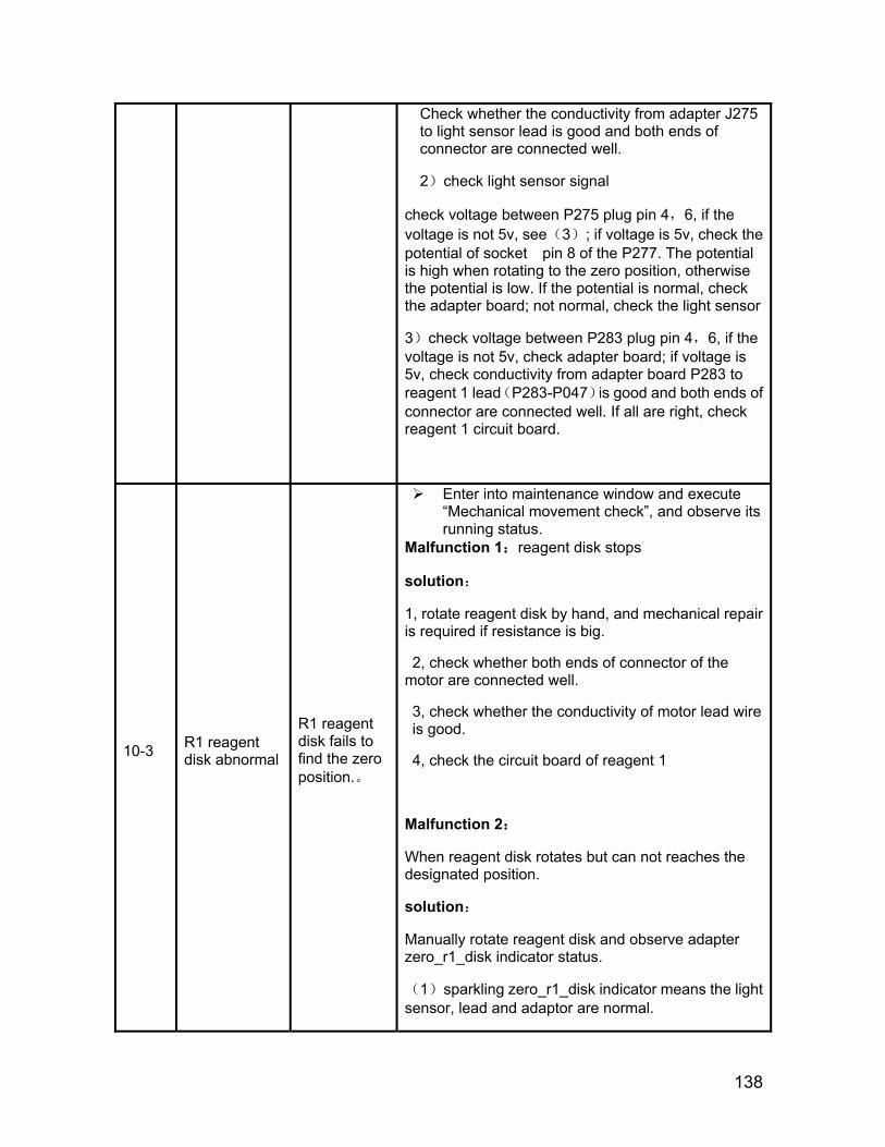
138
Check whether the conductivity from adapter J275 to light sensor lead is good and both ends of connector are connected well.
2)check light sensor signal
check voltage between P275 plug pin 4,6, if the voltage is not 5v, see(3); if voltage is 5v, check the potential of socket pin 8 of the P277. The potential is high when rotating to the zero position, otherwise the potential is low. If the potential is normal, check the adapter board; not normal, check the light sensor
3)check voltage between P283 plug pin 4,6, if the voltage is not 5v, check adapter board; if voltage is 5v, check conductivity from adapter board P283 to reagent 1 lead(P283-P047)is good and both ends of connector are connected well. If all are right, check reagent 1 circuit board.
10-3 R1 reagent disk abnormal
R1 reagent disk fails to find the zero position.。
Enter into maintenance window and execute “Mechanical movement check”, and observe its running status.
Malfunction 1:reagent disk stops
solution:
1, rotate reagent disk by hand, and mechanical repair is required if resistance is big.
2, check whether both ends of connector of the motor are connected well.
3, check whether the conductivity of motor lead wire is good.
4, check the circuit board of reagent 1
Malfunction 2:
When reagent disk rotates but can not reaches the designated position.
solution:
Manually rotate reagent disk and observe adapter zero_r1_disk indicator status.
(1)sparkling zero_r1_disk indicator means the light sensor, lead and adaptor are normal.
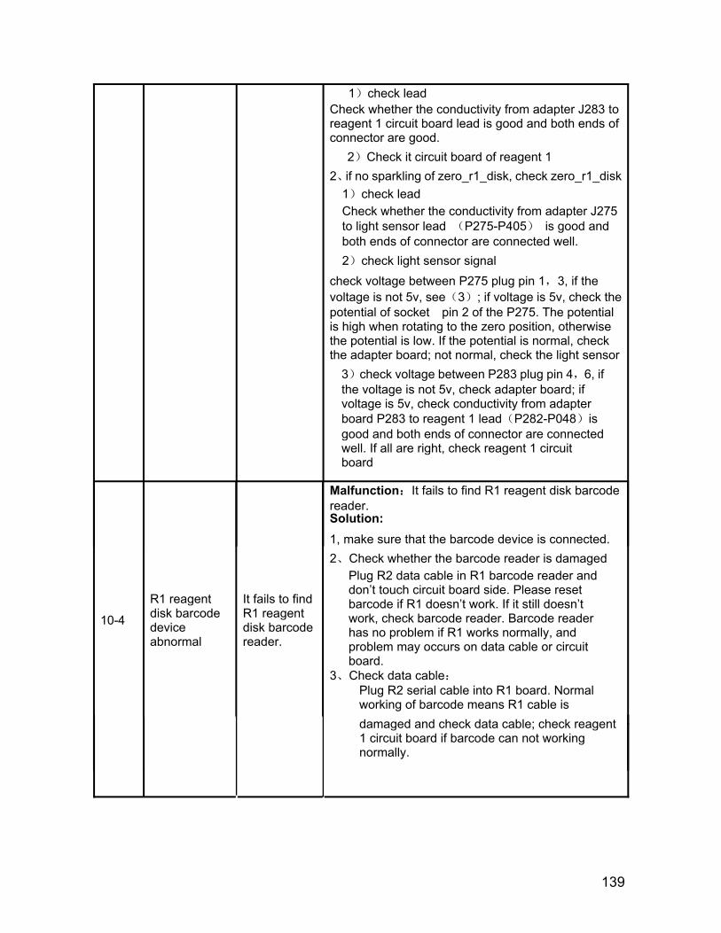
139
1)check lead Check whether the conductivity from adapter J283 to reagent 1 circuit board lead is good and both ends of connector are good.
2)Check it circuit board of reagent 1 2、if no sparkling of zero_r1_disk, check zero_r1_disk
1)check lead Check whether the conductivity from adapter J275 to light sensor lead (P275-P405) is good and both ends of connector are connected well. 2)check light sensor signal
check voltage between P275 plug pin 1,3, if the voltage is not 5v, see(3); if voltage is 5v, check the potential of socket pin 2 of the P275. The potential is high when rotating to the zero position, otherwise the potential is low. If the potential is normal, check the adapter board; not normal, check the light sensor
3)check voltage between P283 plug pin 4,6, if the voltage is not 5v, check adapter board; if voltage is 5v, check conductivity from adapter board P283 to reagent 1 lead(P282-P048)is good and both ends of connector are connected well. If all are right, check reagent 1 circuit board
10-4
R1 reagent disk barcode device abnormal
It fails to find R1 reagent disk barcode reader.
Malfunction:It fails to find R1 reagent disk barcode reader. Solution: 1, make sure that the barcode device is connected. 2、Check whether the barcode reader is damaged
Plug R2 data cable in R1 barcode reader and don’t touch circuit board side. Please reset barcode if R1 doesn’t work. If it still doesn’t work, check barcode reader. Barcode reader has no problem if R1 works normally, and problem may occurs on data cable or circuit board.
3、Check data cable:
Plug R2 serial cable into R1 board. Normal working of barcode means R1 cable is damaged and check data cable; check reagent 1 circuit board if barcode can not working normally.
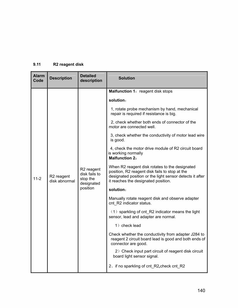
140
9.11 R2 reagent disk
Alarm Code Description Detailed
description Solution
11-2 R2 reagent disk abnormal
R2 reagent disk fails to stop the designated position
Malfunction 1:reagent disk stops
solution:
1, rotate probe mechanism by hand, mechanical repair is required if resistance is big.
2, check whether both ends of connector of the motor are connected well.
3, check whether the conductivity of motor lead wire is good.
4, check the motor drive module of R2 circuit board is working normally Malfunction 2:
When R2 reagent disk rotates to the designated position, R2 reagent disk fails to stop at the designated position or the light sensor detects it after it reaches the designated position.
solution:
Manually rotate reagent disk and observe adapter cnt_R2 indicator status.
(1)sparkling of cnt_R2 indicator means the light sensor, lead and adapter are normal.
1)check lead
Check whether the conductivity from adapter J284 to reagent 2 circuit board lead is good and both ends of connector are good.
2)Check input part circuit of reagent disk circuit board light sensor signal.
2、if no sparkling of cnt_R2,check cnt_R2
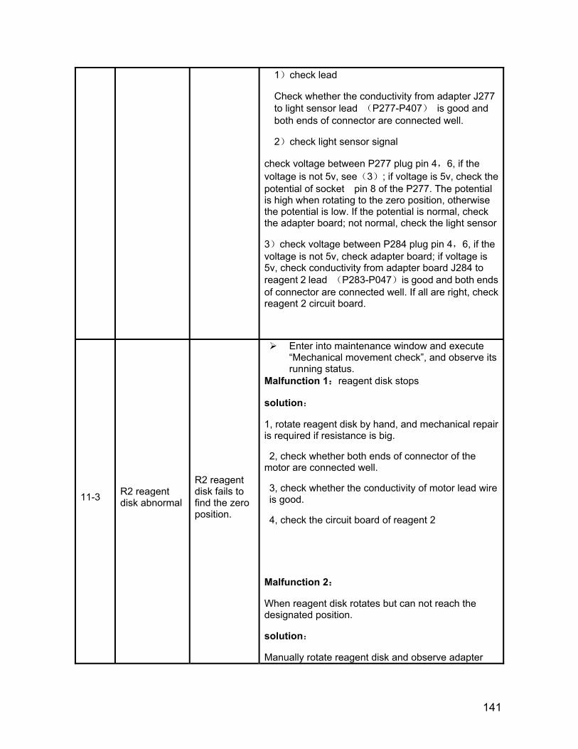
141
1)check lead
Check whether the conductivity from adapter J277 to light sensor lead (P277-P407) is good and both ends of connector are connected well.
2)check light sensor signal
check voltage between P277 plug pin 4,6, if the voltage is not 5v, see(3); if voltage is 5v, check the potential of socket pin 8 of the P277. The potential is high when rotating to the zero position, otherwise the potential is low. If the potential is normal, check the adapter board; not normal, check the light sensor
3)check voltage between P284 plug pin 4,6, if the voltage is not 5v, check adapter board; if voltage is 5v, check conductivity from adapter board J284 to reagent 2 lead (P283-P047)is good and both ends of connector are connected well. If all are right, check reagent 2 circuit board.
11-3 R2 reagent disk abnormal
R2 reagent disk fails to find the zero position.
Enter into maintenance window and execute “Mechanical movement check”, and observe its running status.
Malfunction 1:reagent disk stops
solution:
1, rotate reagent disk by hand, and mechanical repair is required if resistance is big.
2, check whether both ends of connector of the motor are connected well.
3, check whether the conductivity of motor lead wire is good.
4, check the circuit board of reagent 2
Malfunction 2:
When reagent disk rotates but can not reach the designated position.
solution:
Manually rotate reagent disk and observe adapter
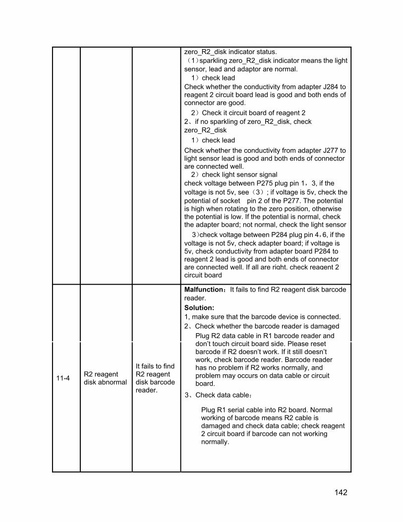
142
zero_R2_disk indicator status. (1)sparkling zero_R2_disk
indicator means the light
sensor, lead and adaptor are normal. 1)check lead
Check whether the conductivity from adapter J284 to reagent 2 circuit board lead is good and both ends of connector are good.
2)Check it circuit board of reagent 2 2、if no sparkling of zero_R2_disk, check zero_R2_disk
1)check lead Check whether the conductivity from adapter J277 to light sensor lead is good and both ends of connector are connected well.
2)check light sensor signal check voltage between P275 plug pin 1,3, if the voltage is not 5v, see(3); if voltage is 5v, check the potential of socket pin 2 of the P277. The potential is high when rotating to the zero position, otherwise the potential is low. If the potential is normal, check the adapter board; not normal, check the light sensor
3)check voltage between P284 plug pin 4,6, if the voltage is not 5v, check adapter board; if voltage is 5v, check conductivity from adapter board P284 to reagent 2 lead is good and both ends of connector are connected well. If all are right, check reagent 2 circuit board
11-4 R2 reagent disk abnormal
It fails to find R2 reagent disk barcode reader.
Malfunction:It fails to find R2 reagent disk barcode reader. Solution: 1, make sure that the barcode device is connected. 2、Check whether the barcode reader is damaged
Plug R2 data cable in R1 barcode reader and don’t touch circuit board side. Please reset barcode if R2 doesn’t work. If it still doesn’t work, check barcode reader. Barcode reader has no problem if R2 works normally, and problem may occurs on data cable or circuit board.
3、Check data cable:
Plug R1 serial cable into R2 board. Normal working of barcode means R2 cable is damaged and check data cable; check reagent 2 circuit board if barcode can not working normally.
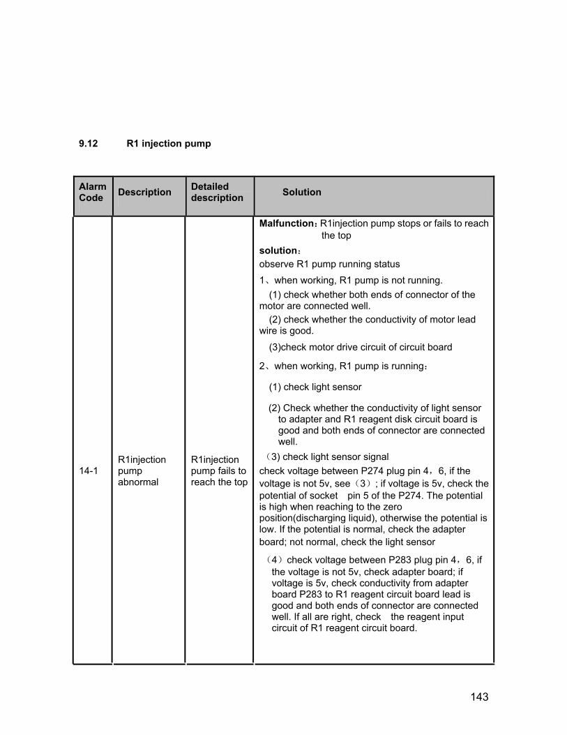
143
9.12 R1 injection pump
Alarm Code Description Detailed
description Solution
14-1 R1injection pump abnormal
R1injection pump fails to reach the top
Malfunction:R1injection pump stops or fails to reach the top
solution:
observe R1 pump running status
1、when working, R1 pump is not running. (1) check whether both ends of connector of the
motor are connected well. (2) check whether the conductivity of motor lead
wire is good.
(3)check motor drive circuit of circuit board
2、when working, R1 pump is running:
(1) check light sensor
(2) Check whether the conductivity of light sensor to adapter and R1 reagent disk circuit board is good and both ends of connector are connected well.
(3) check light sensor signal check voltage between P274 plug pin 4,6, if the voltage is not 5v, see(3); if voltage is 5v, check the potential of socket pin 5 of the P274. The potential is high when reaching to the zero position(discharging liquid), otherwise the potential is low. If the potential is normal, check the adapter board; not normal, check the light sensor
(4)check voltage between P283 plug pin 4,6, if the voltage is not 5v, check adapter board; if voltage is 5v, check conductivity from adapter board P283 to R1 reagent circuit board lead is good and both ends of connector are connected well. If all are right, check the reagent input circuit of R1 reagent circuit board.
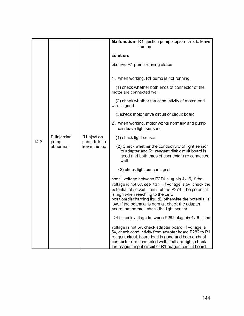
144
14-2 R1injection pump abnormal
R1injection pump fails to leave the top
Malfunction:R1injection pump stops or fails to leave the top
solution:
observe R1 pump running status
1、when working, R1 pump is not running.
(1) check whether both ends of connector of the motor are connected well.
(2) check whether the conductivity of motor lead wire is good.
(3)check motor drive circuit of circuit board
2、when working, motor works normally and pump can leave light sensor:
(1) check light sensor
(2) Check whether the conductivity of light sensor to adapter and R1 reagent disk circuit board is good and both ends of connector are connected well.
(3) check light sensor signal
check voltage between P274 plug pin 4,6, if the voltage is not 5v, see(3); if voltage is 5v, check the potential of socket pin 5 of the P274. The potential is high when reaching to the zero position(discharging liquid), otherwise the potential is low. If the potential is normal, check the adapter board; not normal, check the light sensor
(4)check voltage between P282 plug pin 4,6, if the
voltage is not 5v, check adapter board; if voltage is 5v, check conductivity from adapter board P282 to R1 reagent circuit board lead is good and both ends of connector are connected well. If all are right, check the reagent input circuit of R1 reagent circuit board.

145
9.13 R2 injection pump
Alarm Code Description Detailed
description Solution
15-1 R2 injection pump abnormal
R2 injection pump fails to reach the top
Malfunction:R2 injection pump stops or fails to leave the top
solution:
observe R2 pump running status
1、when working, R2 pump is not running.
(1) check whether both ends of connector of the motor are connected well.
(2) check whether the conductivity of motor lead wire is good.
(3)check motor drive circuit of circuit board
2、when working, motor works normally and pump can leave light sensor:
(1) check light sensor
(2) Check whether the conductivity of light sensor to adapter and R2 reagent disk circuit board is good and both ends of connector are connected well.
(3) check light sensor signal
check voltage between P274 plug pin 8,9, if the voltage is not 5v, see(3); if voltage is 5v, check the potential of socket pin 8 of the P274. The potential is high when rotating to the zero position(discharging liquid), otherwise the potential is low. If the potential is normal, check the adapter board; not normal, check the light sensor
(4)check voltage between P282 plug pin 4,6, if the voltage is not 5v, check adapter board; if voltage is 5v, check conductivity from adapter board P282 to R1 reagent circuit board lead (P282-P037) is good and both ends of connector are connected well. If all are right, check the reagent input circuit of R2 reagent circuit board.

146
15-2 R2 injection pump abnormal
R2 injection pump fails to leave the top
Malfunction:R2 injection pump stops or fails to leave the top
solution:
observe R2 pump running status
1、when working, R2 pump is not running.
(1) check whether both ends of connector of the motor are connected well.
(2) check whether the conductivity of motor lead wire is good.
(3)check motor drive circuit of circuit board
2、when working, motor works normally and pump can leave light sensor:
(1) check light sensor
(2) Check whether the conductivity of light sensor to adapter and R2 reagent disk circuit board is good and both ends of connector are connected well.
(3) check light sensor signal
check voltage between P274 plug pin 8,9, if the voltage is not 5v, see(3); if voltage is 5v, check the potential of socket pin 8 of the P274. The potential is high when reaching to the zero position (discharging liquid), otherwise the potential is low. If the potential is normal, check the adapter board; not normal, check the light sensor
(4)check voltage between P282 plug pin 4,6, if the voltage is not 5v, check adapter board; if voltage is 5v, check conductivity from adapter board P282 to R1 reagent circuit board lead (P282-P037) is good and both ends of connector are connected well. If all are right, check the reagent input circuit of R2 reagent circuit board.
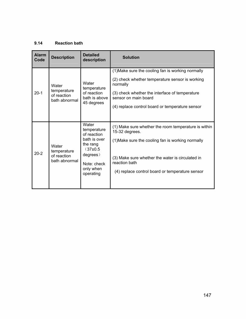
147
9.14 Reaction bath
Alarm Code Description Detailed
description Solution
20-1
Water temperature of reaction bath abnormal
Water temperature of reaction bath is above 45 degrees
(1)Make sure the cooling fan is working normally
(2) check whether temperature sensor is working normally
(3) check whether the interface of temperature sensor on main board
(4) replace control board or temperature sensor
20-2
Water temperature of reaction bath abnormal
Water temperature of reaction bath is over the rang (37±0.5 degrees)
Note: check only when operating
(1) Make sure whether the room temperature is within 15-32 degrees.
(1)Make sure the cooling fan is working normally
(3) Make sure whether the water is circulated in reaction bath
(4) replace control board or temperature sensor
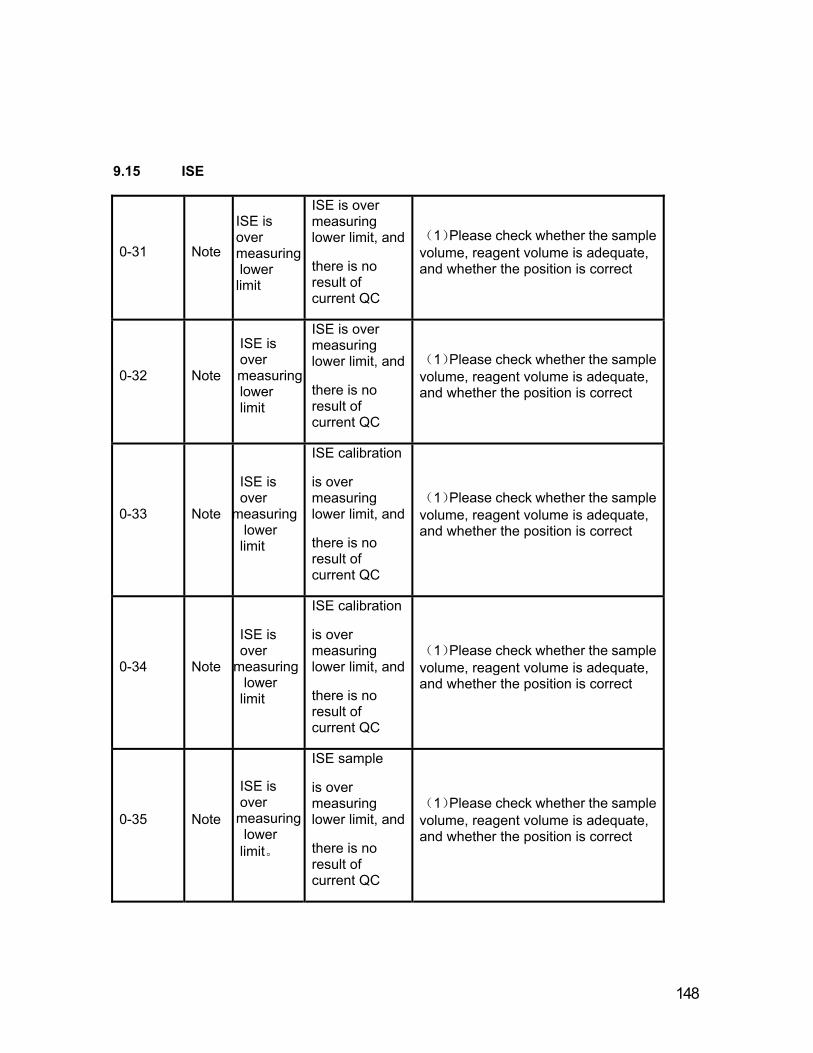
lower measuring
lower measuring
lower measuring
lower measuring
measuring lower
148
9.15 ISE
0-31 Note
ISE is over
limit
ISE is over measuring lower limit, and
there is no result of current QC
(1)Please check whether the sample volume, reagent volume is adequate, and whether the position is correct
0-32 Note
ISE is over
limit
ISE is over measuring lower limit, and
there is no result of current QC
(1)Please check whether the sample volume, reagent volume is adequate, and whether the position is correct
0-33 Note
ISE is over
limit
ISE calibration
is over measuring lower limit, and
there is no result of current QC
(1)Please check whether the sample volume, reagent volume is adequate, and whether the position is correct
0-34 Note
ISE is over
limit
ISE calibration
is over measuring lower limit, and
there is no result of current QC
(1)Please check whether the sample volume, reagent volume is adequate, and whether the position is correct
0-35 Note
ISE is over
limit。
ISE sample
is over measuring lower limit, and
there is no result of current QC
(1)Please check whether the sample volume, reagent volume is adequate, and whether the position is correct
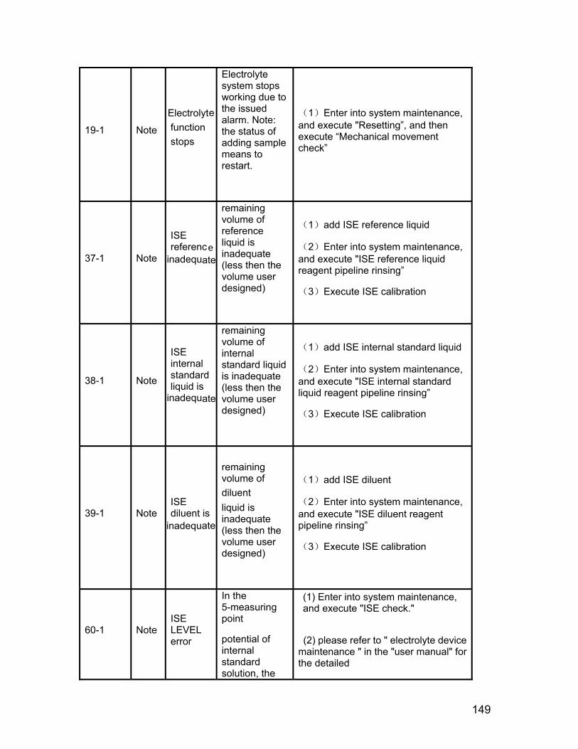
149
19-1 Note
Electrolyte function stops
Electrolyte system stops working due to the issued alarm. Note: the status of adding sample means to restart.
(1)Enter into system maintenance, and execute "Resetting”, and then execute “Mechanical movement check”
37-1 Note
ISE referenc
inadequate
remaining volume of reference liquid is inadequate (less then the volume user designed)
(1)add ISE reference liquid
(2)Enter into system maintenance, and execute "ISE reference liquid reagent pipeline rinsing”
(3)Execute ISE calibration
38-1 Note
ISE internal standard liquid is
inadequate
remaining volume of internal standard liquid is inadequate (less then the volume user designed)
(1)add ISE internal standard liquid
(2)Enter into system maintenance, and execute "ISE internal standard liquid reagent pipeline rinsing”
(3)Execute ISE calibration
39-1 Note ISE diluent is
remaining volume of diluent liquid is inadequate (less then the volume user designed)
(1)add ISE diluent
(2)Enter into system maintenance, and execute "ISE diluent reagent pipeline rinsing”
(3)Execute ISE calibration
60-1 Note ISE LEVEL error
In the 5-measuring point
potential of internal standard solution, the
(1) Enter into system maintenance, and execute "ISE check."
(2) please refer to " electrolyte device maintenance " in the "user manual" for the detailed
e
inadequate
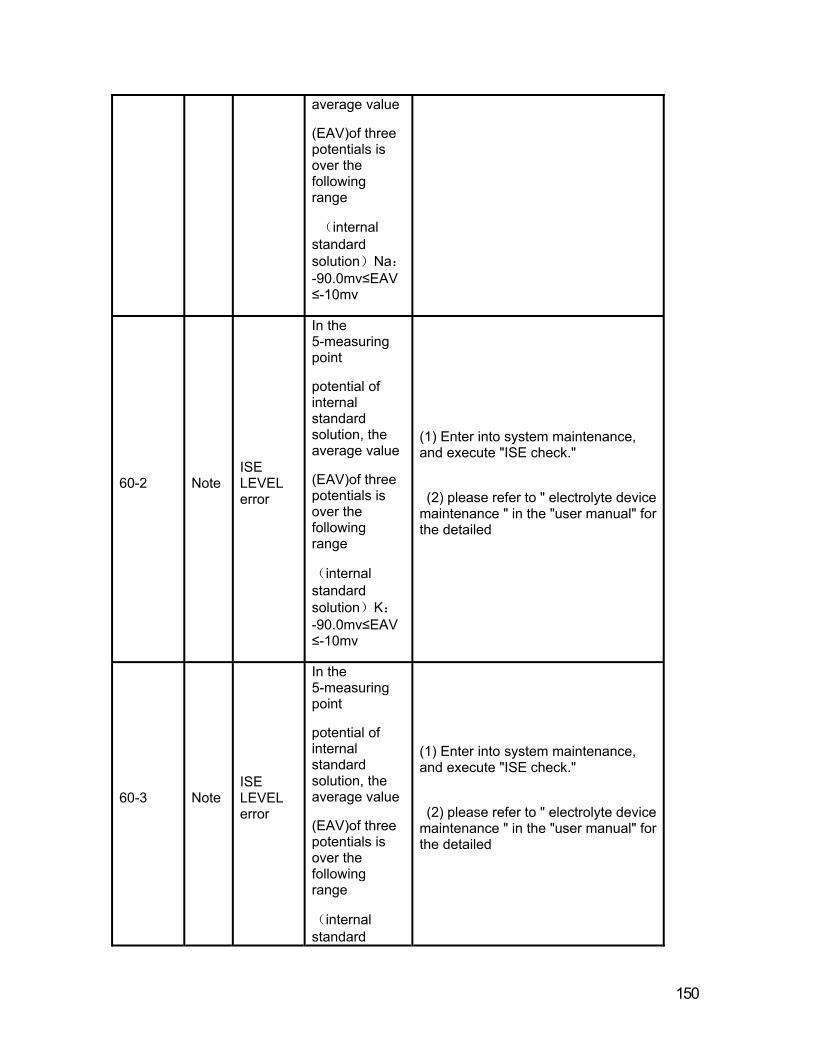
150
average value
(EAV)of three potentials is over the following range
(internal standard solution)Na:-90.0mv≤EAV≤-10mv
60-2 Note ISE LEVEL error
In the 5-measuring point
potential of internal standard solution, the average value
(EAV)of three potentials is over the following range
(internal standard solution)K:-90.0mv≤EAV≤-10mv
(1) Enter into system maintenance, and execute "ISE check."
(2) please refer to " electrolyte device maintenance " in the "user manual" for the detailed
60-3 Note ISE LEVEL error
In the 5-measuring point
potential of internal standard solution, the average value
(EAV)of three potentials is over the following range
(internal standard
(1) Enter into system maintenance, and execute "ISE check."
(2) please refer to " electrolyte device maintenance " in the "user manual" for the detailed
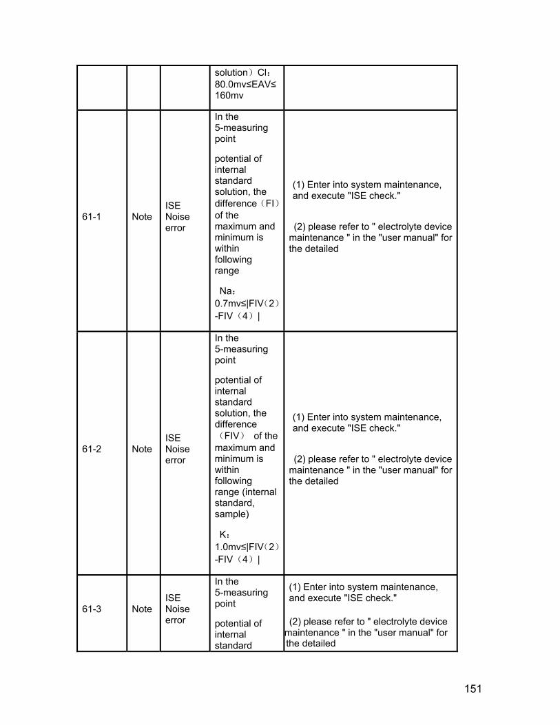
151
solution)Cl:80.0mv≤EAV≤160mv
61-1 Note ISE Noise error
In the 5-measuring point
potential of internal standard solution, the difference(FI)of the maximum and minimum is within following range
Na:0.7mv≤|FIV(2)-FIV(4)|
(1) Enter into system maintenance, and execute "ISE check."
(2) please refer to " electrolyte device maintenance " in the "user manual" for the detailed
61-2 Note ISE Noise error
In the 5-measuring point
potential of internal standard solution, the difference(FIV) of the maximum and minimum is within following range (internal standard, sample)
K:1.0mv≤|FIV(2)-FIV(4)|
(1) Enter into system maintenance, and execute "ISE check."
(2) please refer to " electrolyte device maintenance " in the "user manual" for the detailed
61-3 Note ISE Noise error
In the 5-measuring point
potential of internal standard
(1) Enter into system maintenance, and execute "ISE check."
(2) please refer to " electrolyte device maintenance " in the "user manual" for the detailed
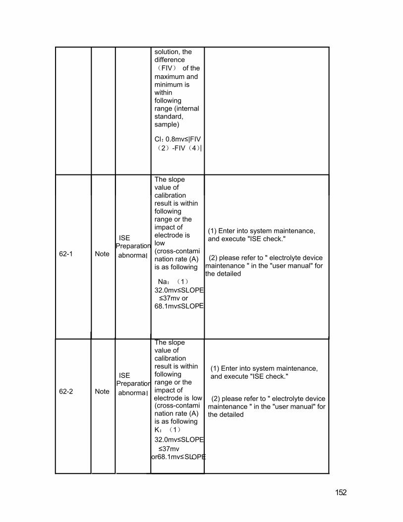
152
solution, the difference(FIV) of the maximum and minimum is within following range (internal standard, sample)
Cl:0.8mv≤|FIV(2)-FIV(4)|
62-1 Note
ISE Preparation abnormal
The slope value of calibration result is within following range or the impact of electrode is low (cross-contamination rate (A) is as following
Na:(1)32.0mv≤SLOPE≤37mv or
68.1mv≤SLOPE
(1) Enter into system maintenance, and execute "ISE check."
(2) please refer to " electrolyte device maintenance " in the "user manual" for the detailed
62-2 Note
ISE Preparation abnormal
The slope value of calibration result is within following range or the impact of electrode is low (cross-contamination rate (A) is as following K:(1)32.0mv≤SLOP
(1) Enter into system maintenance, and execute "ISE check."
(2) please refer to " electrolyte device maintenance " in the "user manual" for the detailed
E≤37mv
or68.1mv≤SLOPE
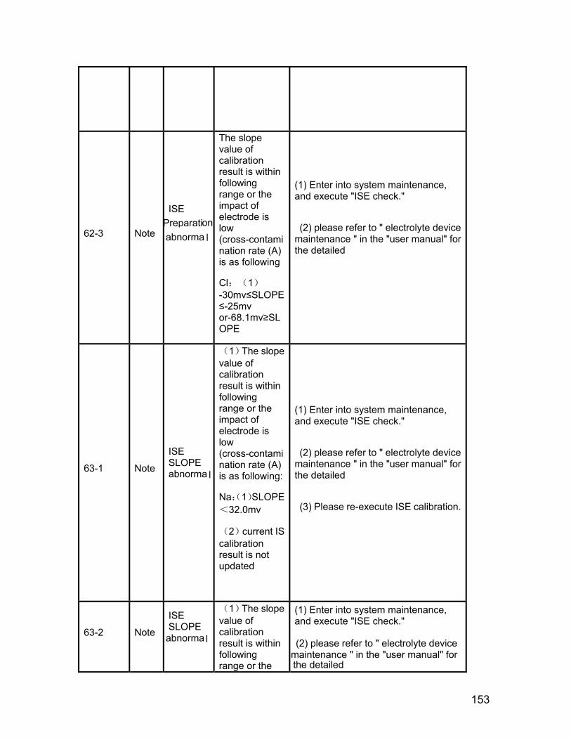
153
62-3 Note
ISE Preparation abnorma l
The slope value of calibration result is within following range or the impact of electrode is low (cross-contamination rate (A) is as following
Cl:(1)-30mv≤SLOPE≤-25mv or-68.1mv≥SLOPE
(1) Enter into system maintenance, and execute "ISE check."
(2) please refer to " electrolyte device maintenance " in the "user manual" for the detailed
63-1 Note
ISE SLOPE abnorma l
(1)The slope value of calibration result is within following range or the impact of electrode is low (cross-contamination rate (A) is as following:
Na:(1)SLOPE<32.0mv
(2)current IS calibration result is not updated
(1) Enter into system maintenance, and execute "ISE check."
(2) please refer to " electrolyte device maintenance " in the "user manual" for the detailed
(3) Please re-execute ISE calibration.
63-2 Note
ISE SLOPE
abnorma l
(1)The slope value of calibration result is within following range or the
(1) Enter into system maintenance, and execute "ISE check."
(2) please refer to " electrolyte device maintenance " in the "user manual" for the detailed

154
impact of electrode is low (cross-contamination rate (A) is as following:K:(1)SLOPE<32mv
(2)current IS calibration result is not updated
(3) Please re-execute ISE calibration.
63-3 Note
ISE SLOPE abnormal
(1)The slope value of calibration result is within following range or the impact of electrode is low (cross-contamination rate (A) is as following:Cl:(1)SLOPE>-25.0mv
(2)current IS calibration result is not updated
(1) Enter into system maintenance, and execute "ISE check."
(2) please refer to " electrolyte device maintenance " in the "user manual" for the detailed
(3) Please re-execute ISE calibration.
64-1 Note
ISE the concentration of internal liquid abnorma l
(1)the concentration of internal liquid(C(IS))is within following range :Na:C(IS)<120.0mmol/l or 190.0mmol/<C(IS)。 (2)current IS calibration result is not
(1) Enter into system maintenance, and execute "ISE check."
(2) please refer to " electrolyte device maintenance " in the "user manual" for the detailed
(3) Please re-execute ISE calibration.
updated
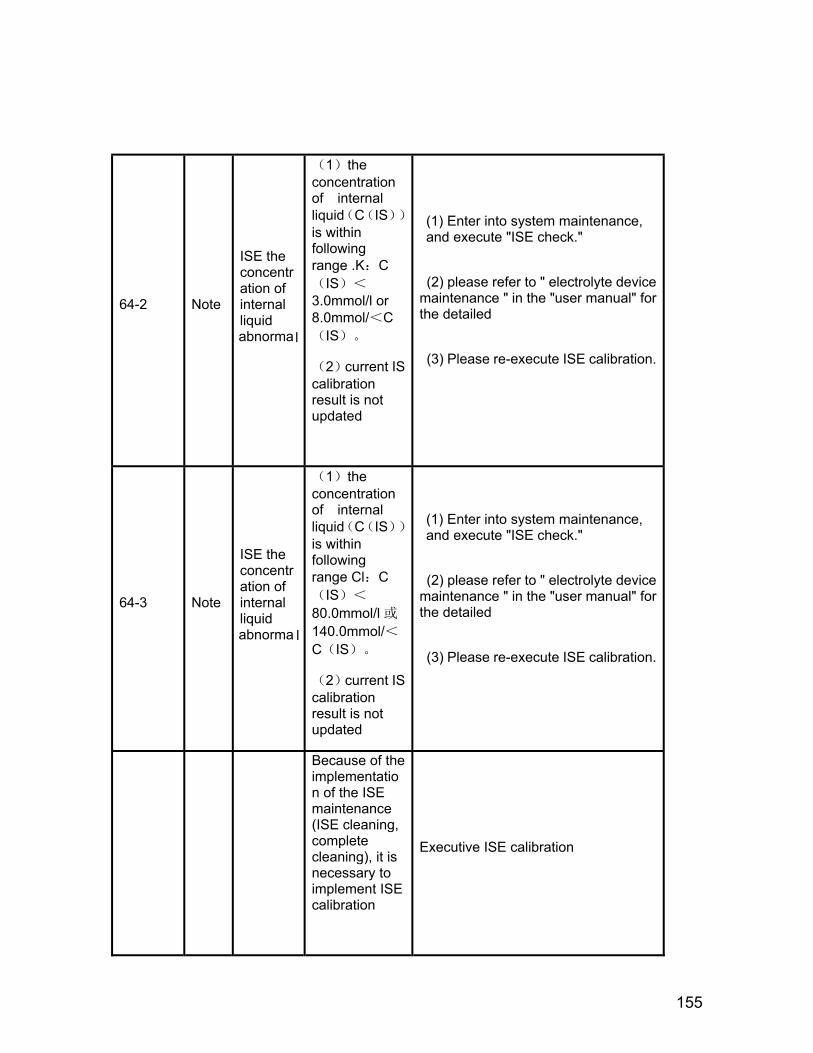
155
64-2 Note
ISE the concentration of internal liquid abnormal
(1)the concentration of internal liquid(C(IS))is within following range .K:C(IS)<3.0mmol/l or 8.0mmol/<C(IS)。
(2)current IS calibration result is not updated
(1) Enter into system maintenance, and execute "ISE check."
(2) please refer to " electrolyte device maintenance " in the "user manual" for the detailed
(3) Please re-execute ISE calibration.
64-3 Note
ISE the concentration of internal liquid abnorma l
(1)the concentration of internal liquid(C(IS))is within following range Cl:C(IS)<
80.0mmol/l 或140.0mmol/<C(IS)。
(2)current IS calibration result is not updated
(1) Enter into system maintenance, and execute "ISE check."
(2) please refer to " electrolyte device maintenance " in the "user manual" for the detailed
(3) Please re-execute ISE calibration.
Because of the implementation of the ISE maintenance (ISE cleaning, complete cleaning), it is necessary to implement ISE calibration
Executive ISE calibration

Alarm Code Description Detailed
description Solution
18-1
SIP injection pump abnormal
SIP injection pump fails to reach the top
Malfunction 1: pump stops or fails to reach the top
solution:
observe pump running status
1、when working, injection pump is not running.
(1) Check whether both ends of connector of the motor are connected well.
(2) Check whether the conductivity of motor lead wire is good.
(3)check motor drive circuit of circuit board
2、when working, injection pump is running:
(1) check light sensor
(2) Check whether the conductivity of light sensor to adapter and ISE circuit board is good and both ends of connector are connected well.
(3) check light sensor signal
check voltage between P901A plug pin 1,3 (measured when plug it into plug seat), if the voltage is 5v, check potential (measured when plug it into plug seat)of P901A plug pin 2,3; The potential is high when reaching to the zero position(discharging liquid), otherwise the potential is low. If the potential is normal, Check whether the conductivity of light sensor to adapter and ISE circuit board is good; if not normal, replace the light sensor
If the voltage is not 5v, check voltage between P190 plug pin 1,3; if voltage is 5v, replace light sensor adapter. If the voltage is not 5v, check input circuit of ISE circuit board.
156
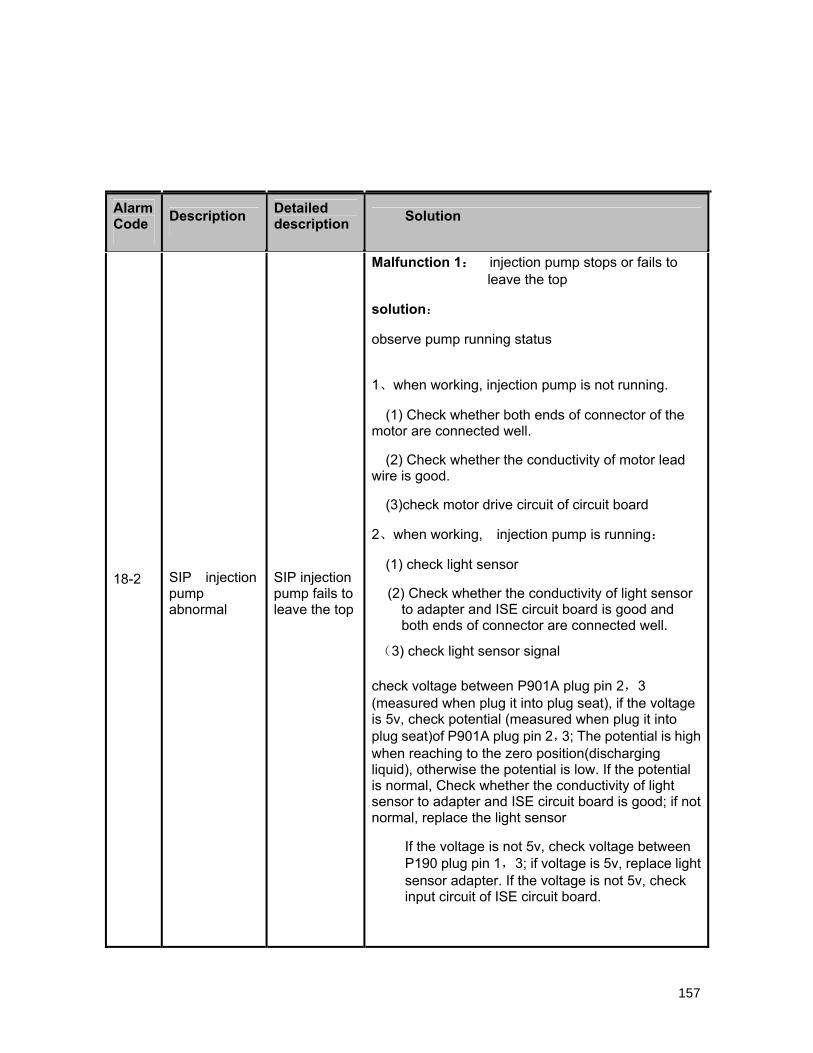
18-2 SIP injection pump abnormal
SIP injection pump fails to leave the top
Malfunction 1: injection pump stops or fails to leave the top
solution:
observe pump running status
1、when working, injection pump is not running.
(1) Check whether both ends of connector of the motor are connected well.
(2) Check whether the conductivity of motor lead wire is good.
(3)check motor drive circuit of circuit board
2、when working, injection pump is running:
(1) check light sensor
(2) Check whether the conductivity of light sensor to adapter and ISE circuit board is good and both ends of connector are connected well.
(3) check light sensor signal
check voltage between P901A plug pin 2,3 (measured when plug it into plug seat), if the voltage is 5v, check potential (measured when plug it into plug seat)of P901A plug pin 2,3; The potential is high when reaching to the zero position(discharging liquid), otherwise the potential is low. If the potential is normal, Check whether the conductivity of light sensor to adapter and ISE circuit board is good; if not normal, replace the light sensor
If the voltage is not 5v, check voltage between P190 plug pin 1,3; if voltage is 5v, replace light sensor adapter. If the voltage is not 5v, check input circuit of ISE circuit board.
157
Alarm Code Description Detailed
description Solution
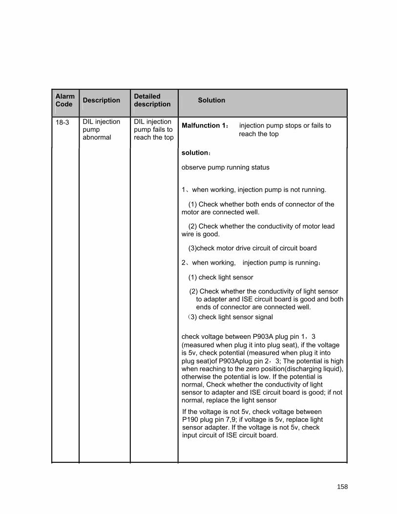
solution:
observe pump running status
1、when working, injection pump is not running.
(1) Check whether both ends of connector of the motor are connected well.
(2) Check whether the conductivity of motor lead wire is good.
(3)check motor drive circuit of circuit board
2、when working, injection pump is running:
(1) check light sensor
(2) Check whether the conductivity of light sensor to adapter and ISE circuit board is good and both ends of connector are connected well.
(3) check light sensor signal
check voltage between P903A plug pin 1,3 (measured when plug it into plug seat), if the voltage is 5v, check potential (measured when plug it into plug seat)of P903Aplug pin 2,3; The potential is high when reaching to the zero position(discharging liquid), otherwise the potential is low. If the potential is normal, Check whether the conductivity of light sensor to adapter and ISE circuit board is good; if not normal, replace the light sensor
If the voltage is not 5v, check voltage between P190 plug pin 7,9; if voltage is 5v, replace light sensor adapter. If the voltage is not 5v, check input circuit of ISE circuit board.
158
158
Alarm Code Description Detailed
description Solution
18-3 DIL injection pump abnormal
DIL injection pump fails to reach the top
Malfunction 1: injection pump stops or fails to reach the top

1、when working, injection pump is not running.
(1) Check whether both ends of connector of the motor are connected well.
(2) Check whether the conductivity of motor lead wire is good.
(3)check motor drive circuit of circuit board
2、when working, injection pump is running:
(1) check light sensor
(2) Check whether the conductivity of light sensor to adapter and ISE circuit board is good and both ends of connector are connected well.
(3) check light sensor signal
check voltage between P903A plug pin 1,3 ug seat), if the voltage
is 5v, check potential (measured when plug it into plug seat)of P903Aplug pin 2,3; The potential is high when reaching to the zero position (discharging liquid), otherwise the potential is low. If the potential is normal, Check whether the conductivity of light sensor to adapter and ISE circuit board is good; if not
If the voltage is not 5v, check voltage between P190 plug pin 7,9; if voltage is 5v, replace light sensor adapter. If the voltage is not 5v, check input circuit of ISE circuit board.
159
Alarm Code Description Detailed
description Solution
18-4 DIL injection pump abnormal
DIL injection pump fails to leave the top
Malfunction 1: injection pump stops or fails to leave the top
solution:
observe pump running status
(measured when plug it into pl
normal, replace the light sensor
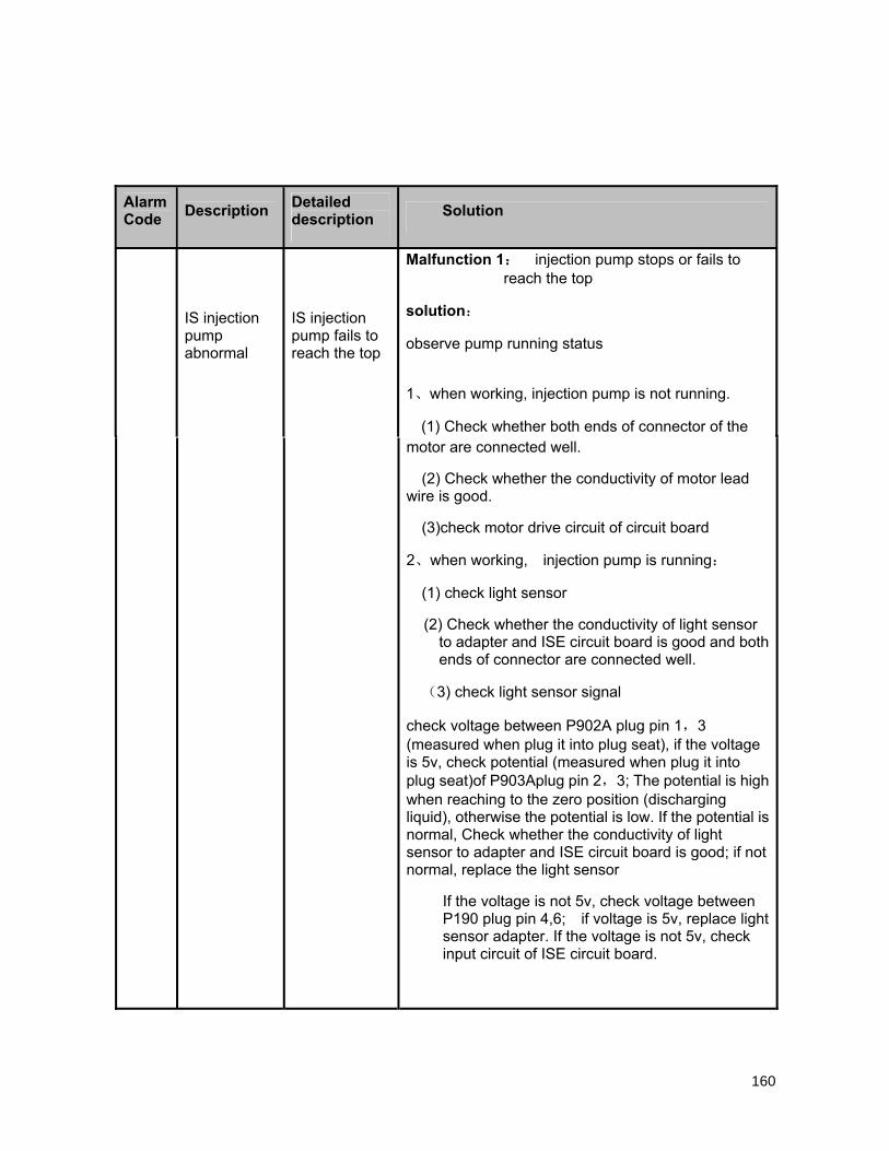
motor are connected well.
(2) Check whether the conductivity of motor lead wire is good.
(3)check motor drive circuit of circuit board
2、when working, injection pump is running:
(1) check light sensor
(2) Check whether the conductivity of light sensor to adapter and ISE circuit board is good and both ends of connector are connected well.
(3) check light sensor signal
check voltage between P902A plug pin 1,3 (measured when plug it into plug seat), if the voltage is 5v, check potential (measured when plug it into plug seat)of P903Aplug pin 2,3; The potential is high when reaching to the zero position (discharging liquid), otherwise the potential is low. If the potential is normal, Check whether the conductivity of light sensor to adapter and ISE circuit board is good; if not normal, replace the light sensor
If the voltage is not 5v, check voltage between P190 plug pin 4,6; if voltage is 5v, replace light sensor adapter. If the voltage is not 5v, check input circuit of ISE circuit board.
160
Alarm Code Description Detailed
description Solution
IS injection pump abnormal
IS injection pump fails to reach the top
Malfunction 1: injection pump stops or fails to reach the top
solution:
observe pump running status
1、when working, injection pump is not running.
(1) Check whether both ends of connector of the

wire is good.
(3)check motor drive circuit of circuit board
2、when working, injection pump is running:
(1) check light sensor
(2) Check whether the conductivity of light sensor to adapter and ISE circuit board is good and both ends of connector are connected well.
(3) check light sensor signal
check voltage between P902A plug pin 1,3 (measured when plug it into plug seat), if the voltage is 5v, check potential (measured when plug it into plug seat)of P902A plug pin 2,3; The potential is high when reaching to the zero position (discharging liquid), otherwise the potential is low. If the potential is normal, Check whether the conductivity of light sensor to adapter and ISE circuit board is good; if not normal, replace the light sensor
If the voltage is not 5v, check voltage between P190 plug pin 4,6; if voltage is 5v, replace light sensor adapter. If the voltage is not 5v, check input circuit of ISE circuit board.
161
Alarm Code Description Detailed
description Solution
18-6 IS injection pump abnormal
IS injection pump fails to leave the top
Malfunction 1: injection pump stops or fails to leave the top
solution:
observe pump running status
1、when working, injection pump is not running.
(1) Check whether both ends of connector of the motor are connected well.
(2) Check whether the conductivity of motor lead
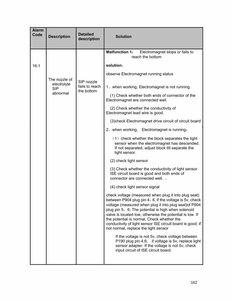
2、when working, Electromagnet is running:
(1)check whether the block separates the light sensor when the electromagnet has descended. If not separated, adjust block till separate the light sensor.
(2) check light sensor
(3) Check whether the conductivity of light sensor ISE circuit board is good and both ends of connector are connected well. 。
(4) check light sensor signal
check voltage (measured when plug it into plug seat) between P904 plug pin 4,6, if the voltage is 5v, check voltage (measured when plug it into plug seat)of P904 plug pin 5,6; The potential is high when solenoid valve is located low, otherwise the potential is low. If the potential is normal, Check whether the conductivity of light sensor ISE circuit board is good; if not normal, replace the light sensor
If the voltage is not 5v, check voltage between P190 plug pin 4,6; if voltage is 5v, replace light sensor adapter. If the voltage is not 5v, check input circuit of ISE circuit board.
162
Alarm Code Description Detailed
description Solution
16-1
The nozzle of electrolyte SIP abnormal
SIP nozzle fails to reach the bottom
Malfunction 1: Electromagnet stops or fails to reach the bottom
solution:
observe Electromagnet running status
1、when working, Electromagnet is not running.
(1) Check whether both ends of connector of the Electromagnet are connected well.
(2) Check whether the conductivity of Electromagnet lead wire is good.
(3)check Electromagnet drive circuit of circuit board

2、when working, Electromagnet is running:
(1)check whether the block left the light sensor when the electromagnet has risen. If not left, adjust block till left the light sensor.
(2) check light sensor
(3) Check whether the conductivity of light sensor ISE circuit board is good and both ends of connector are connected well.
(4) check light sensor signal
check light sensor signal
check voltage (measured when plug it into plug seat) between P904 plug pin 4,6,
if the voltage is 5v, check voltage (measured when plug it into plug seat)of P904 plug pin 5,6; The potential is high when solenoid valve is located low, otherwise the potential is low. If the potential is normal, Check whether the conductivity of light sensor ISE circuit board is good; if good, check light sensor input circuit of ISE circuit board;. If the potential is not normal, replace the light sensor
If the voltage is not 5v, Check whether the conductivity of light sensor ISE circuit board is good; if good, check light sensor input circuit of ISE circuit board
163
Alarm Code Description Detailed
description Solution
16-2 SIP injection pump abnormal
SIP injection pump fails to leave the top
Malfunction 1: Electromagnet stops or fails to leave the top
solution:
observe Electromagnet running status
1、when working, Electromagnet is not running.
(1) Check whether both ends of connector of the Electromagnet are connected well.
(2) Check whether the conductivity of Electromagnet lead wire is good.
(3)check Electromagnet drive circuit of circuit board

Electromagnet lead wire is good.
(3)check Electromagnet drive circuit of circuit board
2、when working, Electromagnet is running:
(1)check whether the block separates the light sensor when the electromagnet has descended. If not separated, adjust block till separate the light sensor.
(2) check light sensor
(3) Check whether the conductivity of light sensor ISE circuit board is good and both ends of connector are connected well. 。
(4) check light sensor signal
check voltage (measured when plug it into plug seat) between P904 plug pin 1,3, if the voltage is 5v, check voltage (measured when plug it into plug seat)of P904 plug pin 2,3; The potential is high when solenoid valve is located low, otherwise the potential is low. If the potential is normal, Check whether the conductivity of light sensor ISE circuit board is good; if not normal, replace the light sensor
If the voltage is not 5v, check voltage between P190 plug pin 4,6; if voltage is 5v, replace light sensor adapter. If the voltage is not 5v, check input circuit of ISE circuit board.
164
Alarm Code Description Detailed
description Solution
17-1
The nozzle of electrolyte SIP abnormal
SIP nozzle fails to reach the bottom
Malfunction 1: Electromagnet stops or fails to reach the bottom
solution:
observe Electromagnet running status
1、when working, Electromagnet is not running.
(1) Check whether both ends of connector of the Electromagnet are connected well.
(2) Check whether the conductivity of

2、when working, Electromagnet is running:
(1)check whether the block left the light sensor when the electromagnet has risen. If not left, adjust block till left the light sensor.
(2) check light sensor
(3) Check whether the conductivity of light sensor ISE circuit board is good and both ends of connector are connected well.
(4) check light sensor signal
check light sensor signal
check voltage (measured when plug it into plug seat) between P904 plug pin1,3,
if the voltage is 5v, check voltage (measured when plug it into plug seat)of P904 plug pin2,3; The potential is high when solenoid valve is located low, otherwise the potential is low. If the potential is normal, Check whether the conductivity of light sensor ISE circuit board is good; if good, check light sensor input circuit of ISE circuit board;. If the potential is not normal, replace the light sensor
If the voltage is not 5v, check voltage between P190 plug pin 4,6; if voltage is 5v, replace light sensor adapter. If the voltage is not 5v, check input circuit of ISE circuit board.
165
17-2 SIP injection pump abnormal
SIP injection pump fails to leave the top
Malfunction 1: Electromagnet stops or fails to leave the top
solution:
observe Electromagnet running status
1、when working, Electromagnet is not running.
(1) Check whether both ends of connector of the Electromagnet are connected well.
(2) Check whether the conductivity of Electromagnet lead wire is good.
(3)check Electromagnet drive circuit of circuit board

overtime error board are normal.
143-3 AD board reset failure
AD board detects malfunction when resetting, AD board reset failure。
Use control panel monitoring software to monitor the fault information to see if there is AD communication error. Repair AD board if there is AD communication error to debug.
143-4 Reaction disk reset failure
Reaction disk detects malfunction
when resetting, Reaction disk reset failure。
Lower machine monitoring software monitors error information, and analyze the reaction disk board-related failure to eliminate the error
143-5 Sample disk
reset failure
Sample disk detects malfunction when resetting, sample disk fails to reset。
Use lower machine monitoring software to monitor error information, and refer to the related information of sample disk board to debug.
143-6 R1 disk reset failure
R1 disk detects malfunction when resetting, R1 disk fails to reset
Use lower machine monitoring software to monitor error information, and refer to the related error information of R1 board to debug.
143-7 R2 disk reset failure
R2 disk detects malfunction when resetting, R2 disk fails to reset
Use lower machine monitoring software to monitor error information, and refer to the related error information of R2 board to debug.
143-8
Water discharging failure of reaction bath
Water discharging failure of reaction bath
Check whether the indication of reaction bath liquid level detector is right; check whether there is remaining water in reaction bath, and check reaction bath water outlet pipeline if there is remaining water in it; check whether relevant electrical units of liquid level detection and control board are normal.
166
143-2
Water adding overtime error
Water tank liquid system malfunction, water adding
Check whether the water supply machine, solenoid valve, pipeline and filter are working normally, and check whether the water supply pipe has air, and check whether the floater is normal, and check whether relevant electrical units of floater and control
Alarm Code Description Detailed
description Solution
143-1 Time synchronization failure
Sending time synchronization order failure
Check the communications of control board and sub-boards respectively.
9.16 Resetting and others
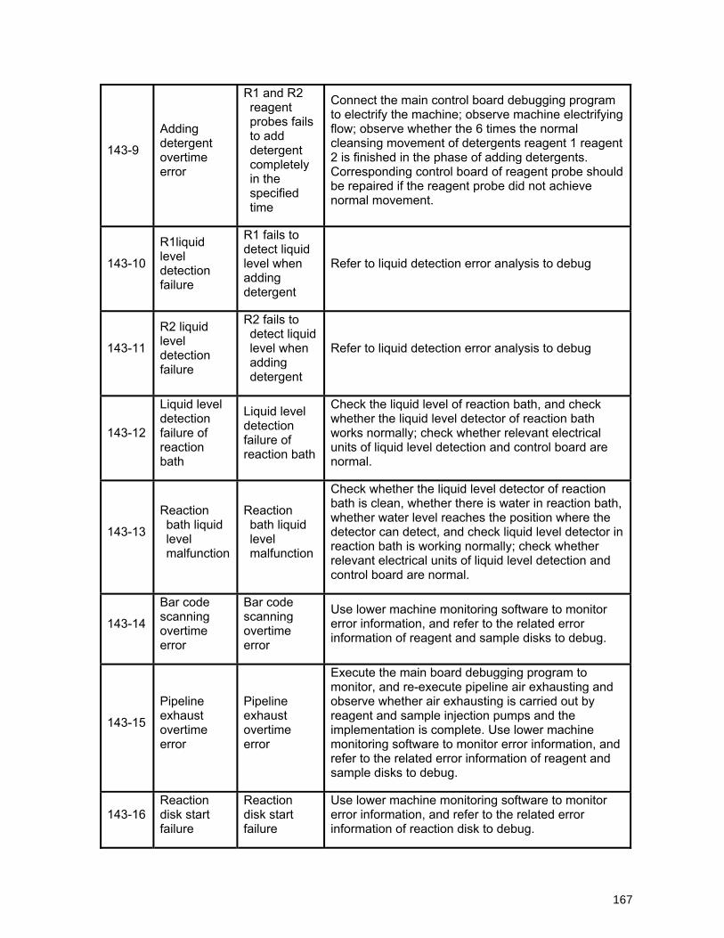
143-9
Adding detergent overtime error
R1 and R2 reagent probes fails to add detergent completely in the specified time
Connect the main control board debugging program to electrify the machine; observe machine electrifying flow; observe whether the 6 times the normal cleansing movement of detergents reagent 1 reagent 2 is finished in the phase of adding detergents. Corresponding control board of reagent probe should be repaired if the reagent probe did not achieve normal movement.
143-10
R1liquid level detection failure
R1 fails to detect liquid level when adding detergent
Refer to liquid detection error analysis to debug
143-11
R2 liquid level detection failure
R2 fails to detect liquid level when adding detergent
Refer to liquid detection error analysis to debug
143-12
Liquid level detection failure of reaction bath
Liquid level detection failure of reaction bath
Check the liquid level of reaction bath, and check whether the liquid level detector of reaction bath works normally; check whether relevant electrical units of liquid level detection and control board are normal.
143-13
Reaction bath liquid level malfunction
Reaction bath liquid level malfunction
Check whether the liquid level detector of reaction bath is clean, whether there is water in reaction bath, whether water level reaches the position where the detector can detect, and check liquid level detector in reaction bath is working normally; check whether relevant electrical units of liquid level detection and control board are normal.
143-14
Bar code scanning overtime error
Bar code scanning overtime error
Use lower machine monitoring software to monitor error information, and refer to the related error information of reagent and sample disks to debug.
143-15
Pipeline exhaust overtime error
Pipeline exhaust overtime error
Execute the main board debugging program to monitor, and re-execute pipeline air exhausting and observe whether air exhausting is carried out by reagent and sample injection pumps and the implementation is complete. Use lower machine monitoring software to monitor error information, and refer to the related error information of reagent and sample disks to debug.
143-16 Reaction disk start failure
Reaction disk start failure
Use lower machine monitoring software to monitor error information, and refer to the related error information of reaction disk to debug.
167

143-17 Reaction disk stop failure
Reaction disk stop failure
Use lower machine monitoring software to monitor error information, and refer to the related error information of reaction disk to debug.
143-18 Sample probe blocked
Sample probe blocked
Maintenance operation of the sample probe. Check whether the pressure sensor and solenoid valve of sample probe pipeline are normal; check whether relevant electrical units of pressure detection and control board are normal.
143-19
Previous sample adding failure
Previous sample adding failure
Use lower machine monitoring software to monitor error information, and refer to the related error information of sample disk to debug.
143-20
Previous reagent 1 adding failure
Previous reagent 1 adding failure
Use lower machine monitoring software to monitor error information, and refer to the related error information of reagent 1 to debug.
143-21
Previous reagent 2 adding failure
Previous reagent 2 adding failure
Use lower machine monitoring software to monitor error information, and refer to the related error information of reagent 2 to debug.
143-22
Previous reagent 3 adding failure
Previous reagent 3 adding failure
Use lower machine monitoring software to monitor error information, and refer to the related error information of reagent 2 to debug.
143-23 Previous reagent 4 adding failure
Previous reagent 4 adding failure
Use lower machine monitoring software to monitor error information, and refer to the related error information of reagent 1 to debug.
143-24 Previous stirring 1 failure
Previous stirring 1 failure
Use lower machine monitoring software to monitor error information, and refer to the related error information of reaction disk to debug.
143-25 Previous stirring 2 failure
Previous stirring 2 failure
Use lower machine monitoring software to monitor error information, and refer to the related error information of reaction disk to debug.
143-26 Previous stirring 3 failure
Previous stirring 3 failure
Use lower machine monitoring software to monitor error information, and refer to the related error information of reaction disk to debug.
143-27 Previous stirring 4 failure
Previous stirring 4 failure
Use lower machine monitoring software to monitor error information, and refer to the related error information of reaction disk to debug.
143-28 Waste liquid bottle full
Waste liquid bottle full
Check whether waste liquid bottle is full; check whether the sensor in waste liquid bottle is normal; check whether relevant electrical units of the floater in
168
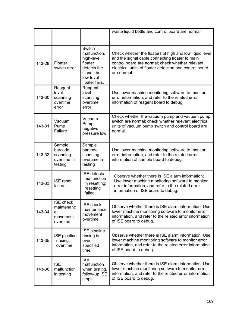
waste liquid bottle and control board are normal.
143-29 Floater switch error
Switch malfunction, high-level floater detects the signal, but low-level floater fails.
Check whether the floaters of high and low liquid level and the signal cable connecting floater to main control board are normal; check whether relevant electrical units of floater detection and control board are normal.
143-30
Reagent level scanning overtime error
Reagent level scanning overtime error
Use lower machine monitoring software to monitor error information, and refer to the related error information of reagent board to debug.
143-31 Vacuum Pump Failure
Vacuum Pump negative pressure low
Check whether the vacuum pump and vacuum pump switch are normal; check whether relevant electrical units of vacuum pump switch and control board are normal.
143-32
Sample barcode scanning overtime in testing
Sample barcode scanning overtime in testing
Use lower machine monitoring software to monitor error information, and refer to the related error information of sample board to debug.
143-33 ISE reset failure
ISE detects malfunction in resetting; resetting failed.
Observe whether there is ISE alarm information; Use lower machine monitoring software to monitor error information, and refer to the related error information of ISE board to debug.
143-34
ISE check maintenance movement overtime
ISE check maintenance movement overtime
Observe whether there is ISE alarm information; Use lower machine monitoring software to monitor error information, and refer to the related error information of ISE board to debug.
143-35 ISE pipeline rinsing overtime
ISE pipeline rinsing is over specified time
Observe whether there is ISE alarm information; Use lower machine monitoring software to monitor error information, and refer to the related error information of ISE board to debug.
143-36 ISE malfunction in testing
ISE malfunction when testing, follow-up ISE stops
Observe whether there is ISE alarm information; Use lower machine monitoring software to monitor error information, and refer to the related error information of ISE board to debug.
169
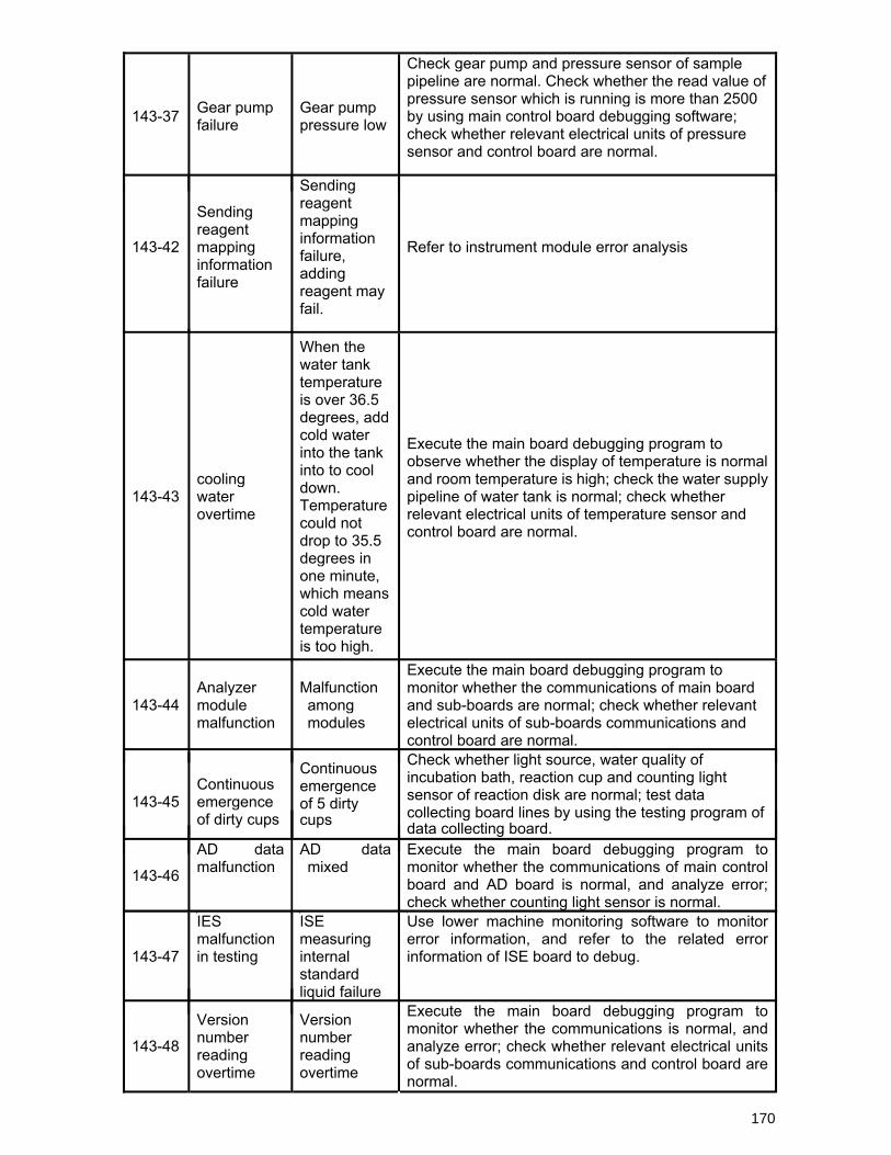
143-37 Gear pump failure
Gear pump pressure low
Check gear pump and pressure sensor of sample pipeline are normal. Check whether the read value of pressure sensor which is running is more than 2500 by using main control board debugging software; check whether relevant electrical units of pressure sensor and control board are normal.
143-42
Sending reagent mapping information failure
Sending reagent mapping information failure, adding reagent may fail.
Refer to instrument module error analysis
143-43 cooling water overtime
When the water tank temperature is over 36.5 degrees, add cold water into the tank into to cool down. Temperature could not drop to 35.5 degrees in one minute, which means cold water temperature is too high.
Execute the main board debugging program to observe whether the display of temperature is normal and room temperature is high; check the water supply pipeline of water tank is normal; check whether relevant electrical units of temperature sensor and control board are normal.
143-44 Analyzer module malfunction
Malfunction among modules
Execute the main board debugging program to monitor whether the communications of main board and sub-boards are normal; check whether relevant electrical units of sub-boards communications and control board are normal.
143-45 Continuous emergence of dirty cups
Continuous emergence of 5 dirty cups
Check whether light source, water quality of incubation bath, reaction cup and counting light sensor of reaction disk are normal; test data collecting board lines by using the testing program of data collecting board.
143-46
AD data malfunction
AD data mixed
Execute the main board debugging program to monitor whether the communications of main control board and AD board is normal, and analyze error; check whether counting light sensor is normal.
170
143-47
IES malfunction in testing
ISE measuring internal standard liquid failure
Use lower machine monitoring software to monitor error information, and refer to the related error information of ISE board to debug.
143-48
Version number reading overtime
Version number reading overtime
Execute the main board debugging program to monitor whether the communications is normal, and analyze error; check whether relevant electrical units of sub-boards communications and control board are normal.
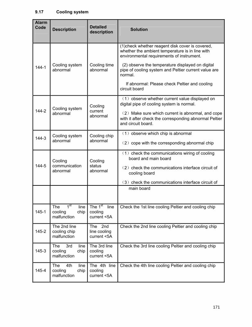
9.17 Cooling system
Alarm Code
Description Detailed
description Solution
144-1 Cooling system abnormal
Cooling time abnormal
(1)check whether reagent disk cover is covered, whether the ambient temperature is in line with environmental requirements of instrument.
(2) observe the temperature displayed on digital pipe of cooling system and Peltier current value are normal.
If abnormal: Please check Peltier and cooling circuit board
144-2 Cooling system abnormal
Cooling current abnormal
(1)observe whether current value displayed on digital pipe of cooling system is normal.
(2)Make sure which current is abnormal, and cope with it after check the corresponding abnormal Peltier and circuit board.
144-3 Cooling system abnormal
Cooling chip abnormal
(1)observe which chip is abnormal
(2)cope with the corresponding abnormal chip
144-5 Cooling communication abnormal
Cooling status abnormal
(1)check the communications wiring of cooling board and main board
(2)check the communications interface circuit of cooling board
(3)check the communications interface circuit of main board
145-1 The 1st line cooling chip malfunction
The 1st line cooling current <5A
Check the 1st line cooling Peltier and cooling chip
145-2 The 2nd line cooling chip malfunction
The 2nd line cooling current <5A
Check the 2nd line cooling Peltier and cooling chip
145-3 The 3rd line cooling chip malfunction
The 3rd line cooling current <5A
Check the 3rd line cooling Peltier and cooling chip
145-4 The 4th line cooling chip malfunction
The 4th line cooling current <5A
Check the 4th line cooling Peltier and cooling chip
171
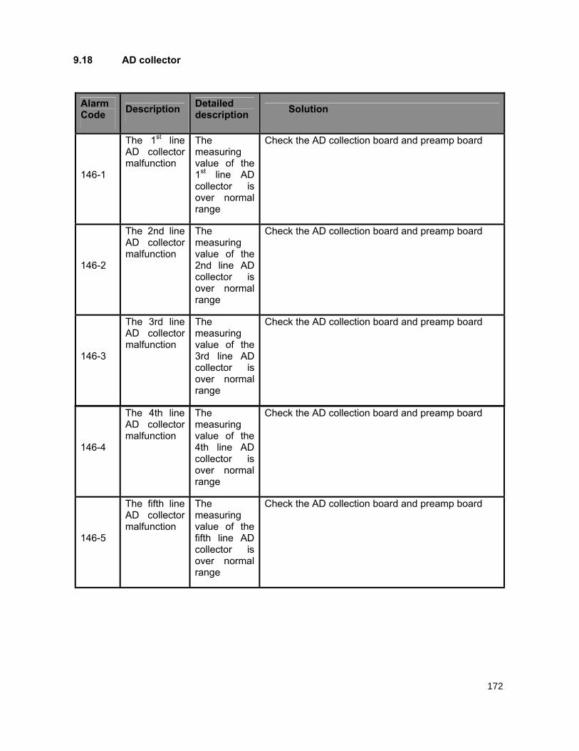
Alarm Code Description Detailed
description Solution
146-1
The 1st line AD collector malfunction
The measuring value of the 1st line AD collector is over normal range
Check the AD collection board and preamp board
146-2
The 2nd line AD collector malfunction
The measuring value of the 2nd line AD collector is over normal range
Check the AD collection board and preamp board
146-3
The 3rd line AD collector malfunction
The measuring value of the 3rd line AD collector is over normal range
Check the AD collection board and preamp board
9.18 AD collector
146-4
The 4th line AD collector malfunction
The measuring value of the 4th line AD collector is over normal range
Check the AD collection board and preamp board
146-5
The fifth line AD collector malfunction
The measuring value of the fifth line AD collector is over normal range
Check the AD collection board and preamp board
172
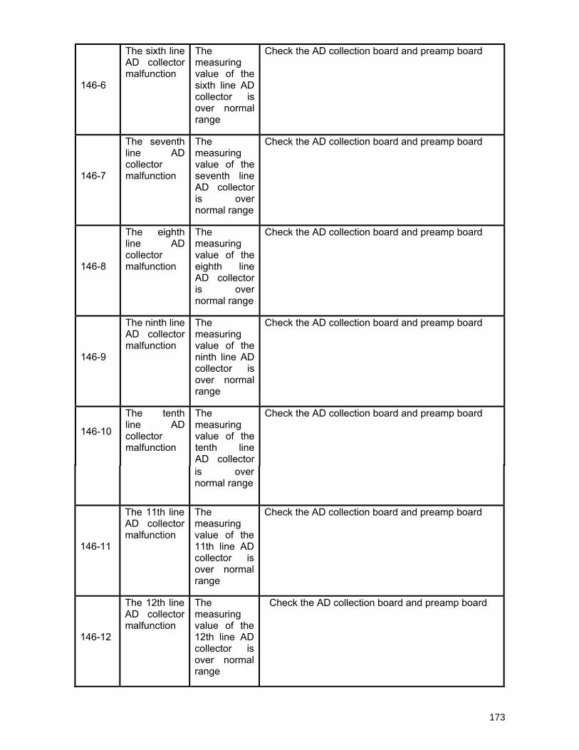
146-6
The sixth line AD collector malfunction
The measuring value of the sixth line AD collector is over normal range
Check the AD collection board and preamp board
146-7
The seventh line AD collector malfunction
The measuring value of the seventh line AD collector is over normal range
Check the AD collection board and preamp board
146-8
The eighth line AD collector malfunction
The measuring value of the eighth line AD collector is over normal range
Check the AD collection board and preamp board
146-9
The ninth line AD collector malfunction
The measuring value of the ninth line AD collector is over normal range
Check the AD collection board and preamp board
146-10
The tenth line AD collector malfunction
The measuring value of the tenth line AD collector
Check the AD collection board and preamp board
is over normal range
146-11
The 11th line AD collector malfunction
The measuring value of the 11th line AD collector is over normal range
Check the AD collection board and preamp board
146-12
The 12th line AD collector malfunction
The measuring value of the 12th line AD collector is over normal range
Check the AD collection board and preamp board
173