cs 453 computer networks lecture 14 medium access control sublayer
TRANSCRIPT

CS 453CS 453Computer NetworksComputer Networks
Lecture 14Lecture 14
Medium Access Control Medium Access Control
SublayerSublayer

Ethernet
Ethernet is by far the most popular LAN technology
I refer to as technology because it is a collection of… Protocols Hardware interfaces Cabling standards…

Ethernet
Ethernet standardize by IEEE As IEEE 802.3
Other important networking standards… IEEE 802.11 – Wireless LAN (WiFi) IEEE 802.15 – Bluetooth IEEE 802.16 – Wireless MAN (WiMax)
We will look at these later
Ethernet
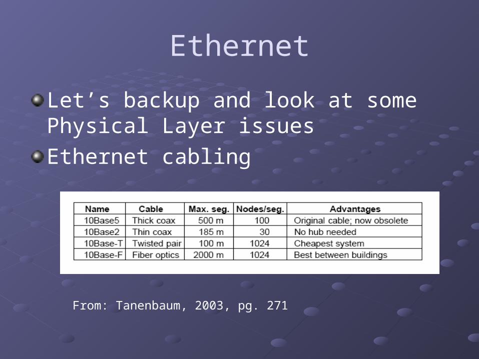
Let’s backup and look at some Physical Layer issues
Ethernet cabling
From: Tanenbaum, 2003, pg. 271

Ethernet10Base5
Early Ethernet Used
thick, heavy, stiff yellow coax cable(RG-8)Vampire tap transceiverTransceiver cable
50 meters Twisted pair Interface in the
computer
From:http://en.wikipedia.org/wiki/10BASE5
From:
www.ozkankaradavut.com/aktel/products.htm

Ethernet10Base2
Thinnet Used thin (RG-58)
coax cable BNC T-connectors No drop cables Thin coax snaked
around computer to computer to printer,…
From: http://en.wikipedia.org/wiki/10BASE2

Ethernet10Base2 Very difficult to
maintain and troubleshoot
“Cable breaks” common occurrence
Took whole segments offline
From: http://en.wikipedia.org/wiki/10BASE2
From: Computer Desktop Encyclopedia, © 1998

Ethernet10BaseT
What most of us know as Ethernet
Uses twisted pair copper cabling
T means twisted pair
Cables connect to hubs
No serial chain connections
Ethernet Hub

Ethernet10BaseT
Remember the bus topology of 10Base5 and 10Base2…
Hub is a bus-in-a-box
Easy installation Simple
troubleshooting Simple
maintenance
Ethernet Hub

Ethernet10BaseF Like 10BaseT but use Fiber cable Very good noise immunity Very secure Good range

Ethernet100BaseT FastEthernet – 100 Mbps
1000BaseT GigabitEthernet – 1000 Mbps
10GigE
100GigE

Ethernet – Bit encoding
We need a way to electrically encode a bit stream on a transmission medium
Binary encoding of a bit stream often involves generating +5 volt for a 1 and 0 volts for 0
This a bad idea because devices can’t distinguish between a binary 0 and a dropped bit
If we use two other voltages we still have a problem with the possibility that the sender and receiver will get out of sync regarding the bit boundaries

Ethernet – Bit encodingManchester Encoding A bit transmission period has two parts 1 = high to low transition during bit period 0 = low to high transition during bit period
From: Tanenbaum, 2003, pg. 275

Ethernet – Bit encodingDifferential Manchester Encoding
A bit transmission period has two parts 1 = no transition during bit period 0 = transition during bit period
Ethernet Manchester Encoding +0.85v =1 -0.85v = 0
Other LAN technologies use Differential Manchester Encoding

Ethernet MAC Sublayer Protocol
General Ethernet Frame description
From: http://en.wikipedia.org/wiki/Ethernet#Ethernet_frame_types_and_the_EtherType_field
Preample: 62 bits –alternating 0,1 announces frame
SFD: 2 bit sequence 11 – Start of Frame Delimiter
Destination Address – 6 bytes
Source Address – 6 bytes
Ethertype – defines protocol or length of data packet
Payload – data packet – minimum size=46 bytes, maximum size=1500 bytes
Frame Check Sequence – Cyclic Redundancy Check on Frame

EthernetFrame specifications Destination address
6 bytes
High order bit 0=normal address 1=Group address (multicast)
Bit 46 (high order -1) Determines if address is local or global
Source address6 bytes – MAC address of sending device

EthernetFrame specifications Destination address
If bit 47 is set to 1 the address is Multicast address
Going to a designated group of addresses
If all destination address bits are set to one address is a broadcast address
Going to all addresses in the ethernet

EthernetFrame specifications Type field
<=1500 defines length of payload packet
>1500 defines of the protocol for handling the packet (what process gets the data)
IP protocol is Type = 2048

EthernetFrame specifications
Payload sizeMin 46 bytes – if legitamate frame is less than 46 bytes Pad field is used to fill it out 64 bytesIf receiver receive smaller payload – its trashWhen a collision is detected detector puts an alarm on the channelIf station A starts a transmission and later B starts a transmission (because of propagation delay) and causes a collision, B puts an alarm on the channelA must be able to “hear” the alarm before it completes the transmission of its frame, and abort…Otherwise, it believes that the transmission was successful
Therefore, the outgoing frame must be long enough to be in transmission at Station A at the worst case time that it could “hear” a collision signal triggered by Station B

EthernetFrame specifications Payload size
This is true for 10 Mbps (10basex) networks
As network speeds get greater
Minimum packet sizes must be get bigger
Or the cable length must get smaller (to reduce propagation delay)

Ethernet: Dealing with Collisions
Ethernet uses CSMA/CD
So what happens when a collision occurs?
Binary Exponential Backoff Algorithm
When a collision occurs… All stations trying to use the channel… … backoff and randomly wait either … 0 or 1 ( like a coin toss) time slots and try
again

Ethernet: Dealing with Collisions
Binary Exponential Backoff AlgorithmWhen a 2nd collision occurs… All colliding stations randomly… …backoff and wait 0,1,2, or 3 time slots, and
retry
If a 3rd collision occurs All colliding stations randomly backoff and… …wait 0,1,2,…,7 time slots and retry
Do you see the pattern in algorithm?

Ethernet: Dealing with Collisions
Binary Exponential Backoff Algorithm On the nth collision… All competing stations backoff and randomly
wait 2n-1 time slots then retry After 10 successive collisions (210 -1 = 1023)
… ….declare defeat and pass the problem to the
Network layer

Ethernet: Dealing with Collisions
Binary Exponential Backoff Algorithm This turns out to work pretty well If the protocol just used the “flip-a-coin”
algorithm ( 0, 22 -1)
If there were 100 competing stations
A frame could not flow until 1 station picked 0 and every other station picked 1…
That could take forever (remember each station is “flipping a coin”)

Ethernet: Dealing with Collisions
Binary Exponential Backoff Algorithm Alternatively, if the algorithm based the
number of wait periods on the number of stations N…
Then the average wait time would be high This would introduce large delays

Ethernet Switches
Hubs – bus-in-a-box All ports on a hub represent one collision
domain
Switches Ports are ganged in small groups (like 4) If frames is destined for port in same group it
is switched there If not, it is placed on a high speed backplane
and routed to another port in another group
Ethernet Switches
Switches Some switches are buffered And have groups of one This means that the collision domains are one And therefore, collisions are not possible, at least in
the group In this case all frames are buffered and move by high
speed backplane to the destination port
Switches can support full duplex transmit/receive Not possible with CSMA/CD

Fast Ethernet
10Base?? Was not fast enough for very longApplications easily outstripped the 10 Mbps (there is trend here!!!)IEEE 802.3 committee tackled this and came up with a few faster versions of EthernetStandard is an extension to 802.3 called IEEE 802.3u or FastEthernet

Fast Ethernet
One constraint with the design of FastEthernet was that it work with existing Cat3 and Cat5 UTP cables
Why Cat3?
For Cat3 –100BaseT4 Unable to run 200 Megabaud (Manchester encoding)
for 100 meters Bumped up the bandwidth from 20 Mhz (standard
Ethernet) to 25 Mhz Requires four Twisted Pairs Dropped Manchester Encoding

Fast Ethernet
100BaseTx Requires Cat5 Only needs two twisted pairs Uses 4B/5B encoding rather than Manchester Full Duplex – 100 Mbps each way
100BaseFx Similar to 100BaseTx but uses fiber One fiber each way – full duplex Long range Good security Expensive
