dc&ac magnetic field measurement of the csns/rcs ... · the radial coil type with bucking...
TRANSCRIPT
DC&AC Magnetic Field Measurement of the CSNS/RCS Quadrupole Magnet
Jianxin Zhou for
Li Li, Baogui Yin, Changdong Deng, Wen Kang, Shinian Fu
IMMW 18 Jun3-7 2013 BNL
Page散裂中子源进展汇报 June 6, 2013 2
Outline
1、Overview of CSNS/RCS magnet system
2、 Introduction of the measurement system
3、The DC magnetic field measurement
4、The AC magnetic field measurement
5、Conclusion
Page散裂中子源进展汇报 June 6, 2013
1、Overview of CSNS/RCS magnet system
3
Page散裂中子源进展汇报 June 6, 2013
1、Overview of CSNS/RCS magnet system
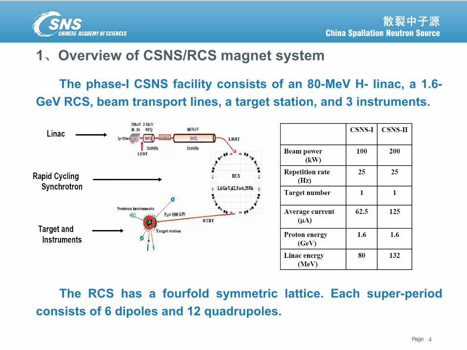
The phase-I CSNS facility consists of an 80-MeV H- linac, a 1.6-GeV RCS, beam transport lines, a target station, and 3 instruments.
4
The RCS has a fourfold symmetric lattice. Each super-periodconsists of 6 dipoles and 12 quadrupoles.
Page散裂中子源进展汇报 June 6, 2013
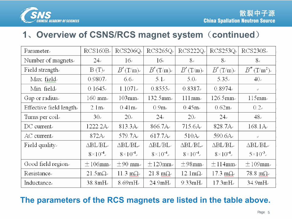
1、Overview of CSNS/RCS magnet system(continued)
The parameters of the RCS magnets are listed in the table above.5
Page散裂中子源进展汇报 June 6, 2013
1、Overview of CSNS/RCS magnet system(continued)
6
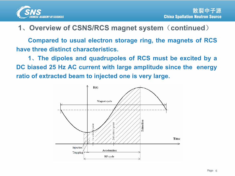
Compared to usual electron storage ring, the magnets of RCShave three distinct characteristics.
1、The dipoles and quadrupoles of RCS must be excited by aDC biased 25 Hz AC current with large amplitude since the energyratio of extracted beam to injected one is very large.
Page散裂中子源进展汇报 June 6, 2013
1、Overview of CSNS/RCS magnet system(continued)
7
2、The magnets have larger apertures than usual ones. Becauseproton beam has a strong space-charge effect, and the practical way toreduce it is to enlarge the acceptance and consequently the magnetapertures.
3、 As waveform control is difficult for the magnets excited by theresonance circuit, the non-linearity of the magnetic field andinductance must be decreased as much as possible.
To study these issues, the prototype magnets for the CSNS/RCShad been fabricated. The magnetic field measurements are needed toverify whether the field quality can meet the RCS accelerator operationrequirements.
A flipping-coil magnetic measurement system and a harmonic coilmeasurement system had been developed to perform the DC and ACfield measurement.
Page散裂中子源进展汇报 June 6, 2013
2、 Introduction of the measurement system
8
Page散裂中子源进展汇报 June 6, 2013
2、Introduction of the measurement system
9
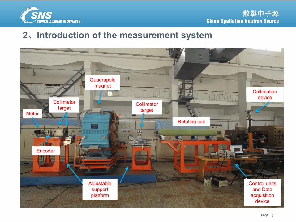
Quadrupole magnet
Rotating coil
Control units and Data
acquisition device
Collimation device
Adjustable support platform
Motor
Encoder
Collimator target
Collimator target
Page散裂中子源进展汇报 June 6, 2013
2、Introduction of the measurement system (continued)
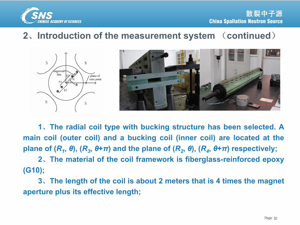
1、The radial coil type with bucking structure has been selected. Amain coil (outer coil) and a bucking coil (inner coil) are located at theplane of (R1, θ), (R3, θ+π) and the plane of (R2, θ), (R4, θ+π) respectively;
2、The material of the coil framework is fiberglass-reinforced epoxy(G10);
3、The length of the coil is about 2 meters that is 4 times the magnetaperture plus its effective length;
10
Page散裂中子源进展汇报 June 6, 2013
2、Introduction of the measurement system (continued)
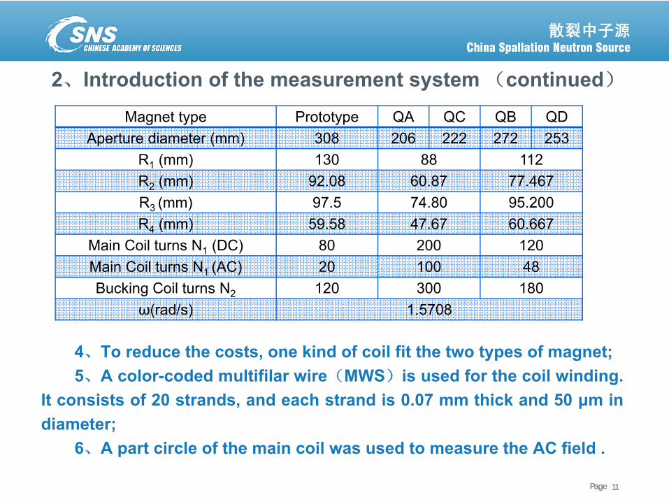
4、To reduce the costs, one kind of coil fit the two types of magnet;5、A color-coded multifilar wire(MWS)is used for the coil winding.
It consists of 20 strands, and each strand is 0.07 mm thick and 50 μm indiameter;
6、A part circle of the main coil was used to measure the AC field .
11
Magnet type Prototype QA QC QB QDAperture diameter (mm) 308 206 222 272 253
R1 (mm) 130 88 112R2 (mm) 92.08 60.87 77.467 R3 (mm) 97.5 74.80 95.200 R4 (mm) 59.58 47.67 60.667
Main Coil turns N1 (DC) 80 200 120Main Coil turns N1 (AC) 20 100 48Bucking Coil turns N2 120 300 180
ω(rad/s) 1.5708
Page散裂中子源进展汇报 June 6, 2013
2、Introduction of the measurement system (continued)
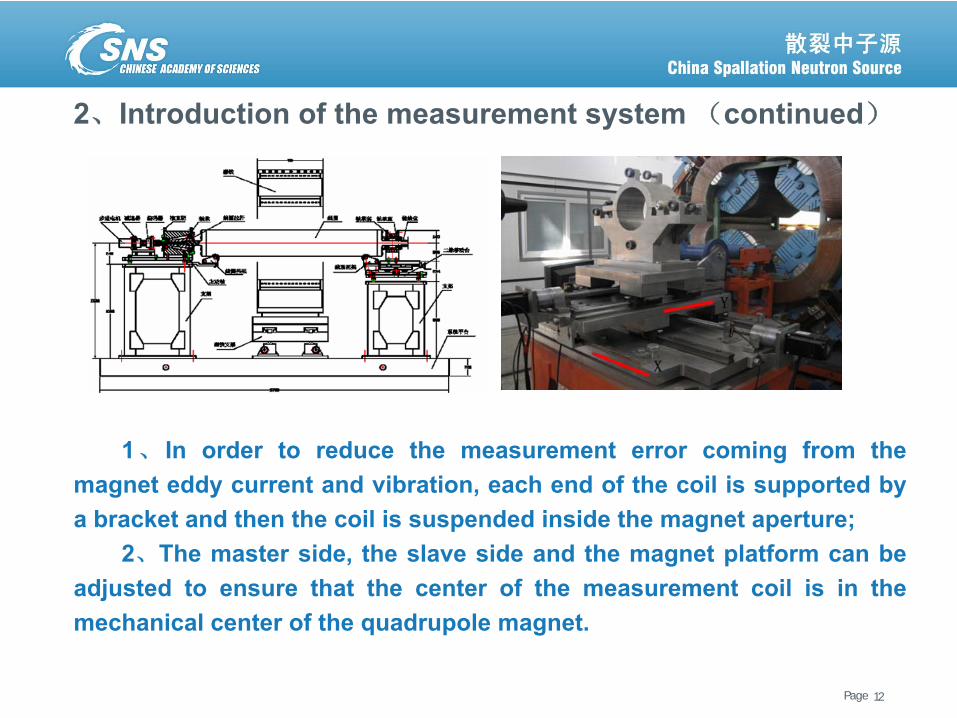
1、 In order to reduce the measurement error coming from themagnet eddy current and vibration, each end of the coil is supported bya bracket and then the coil is suspended inside the magnet aperture;
2、The master side, the slave side and the magnet platform can beadjusted to ensure that the center of the measurement coil is in themechanical center of the quadrupole magnet.
12
Page散裂中子源进展汇报 June 6, 2013
2、Introduction of the measurement system(continued)
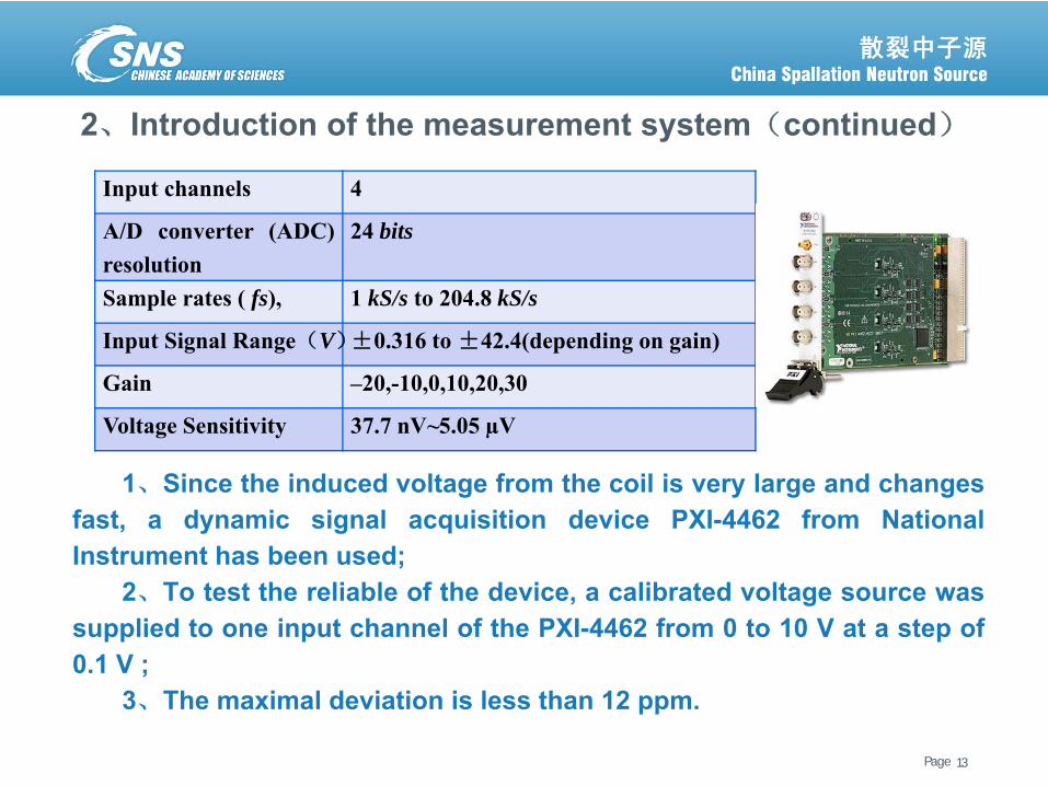
1、Since the induced voltage from the coil is very large and changesfast, a dynamic signal acquisition device PXI-4462 from NationalInstrument has been used;
2、To test the reliable of the device, a calibrated voltage source wassupplied to one input channel of the PXI-4462 from 0 to 10 V at a step of0.1 V ;
3、The maximal deviation is less than 12 ppm.
13
Input channels 4
A/D converter (ADC)resolution
24 bits
Sample rates ( fs), 1 kS/s to 204.8 kS/s
Input Signal Range(V)±0.316 to±42.4(depending on gain)
Gain –20,-10,0,10,20,30
Voltage Sensitivity 37.7 nV~5.05 µV
Page散裂中子源进展汇报 June 6, 2013
2、Introduction of the measurement system(continued)
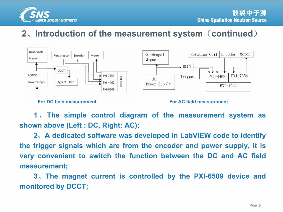
1、The simple control diagram of the measurement system asshown above (Left : DC, Right: AC);
2、A dedicated software was developed in LabVIEW code to identifythe trigger signals which are from the encoder and power supply, it isvery convenient to switch the function between the DC and AC fieldmeasurement;
3、The magnet current is controlled by the PXI-6509 device andmonitored by DCCT;
14
For AC field measurement For DC field measurement
Page散裂中子源进展汇报 June 6, 2013
2、Introduction of the measurement system(continued)
4、PXI-7354 is a motor control device, which is used to control threeservo motors for their corresponding movement;
5、A high-resolution annular encoder (8192 resolutions/cycle) isseated on the drive shaft and looped to the PXI-7354 motion controldevice and the encoder signals are acquired by PXI-4462 at the sametime;
6、The main coil and bucking coil were used to measure DC field. Apart circle of the main coil was used to measure the AC field;
7、The induced voltage of the coils and sequence pulses of encoder(the trigger signal of the power supply)are recorded synchronously bythe separate channels of the PXI-4462.
15
Page散裂中子源进展汇报 June 6, 2013
3、The DC magnetic field measurement
16
Page散裂中子源进展汇报 June 6, 2013
3、The DC magnetic field measurement
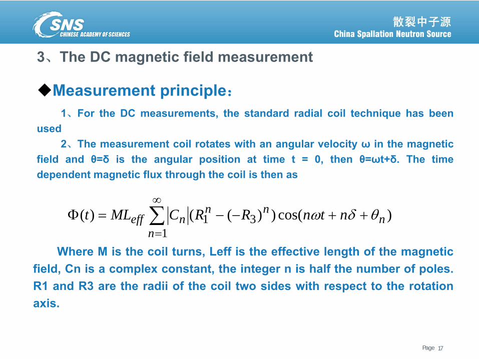
Measurement principle:1、For the DC measurements, the standard radial coil technique has been
used2、The measurement coil rotates with an angular velocity ω in the magnetic
field and θ=δ is the angular position at time t = 0, then θ=ωt+δ. The timedependent magnetic flux through the coil is then as
17
)cos())(()( 311
nnn
nneff ntnRRCMLt θδω ++−−=Φ ∑
∞
=Where M is the coil turns, Leff is the effective length of the magnetic
field, Cn is a complex constant, the integer n is half the number of poles.R1 and R3 are the radii of the coil two sides with respect to the rotationaxis.
Page散裂中子源进展汇报 June 6, 2013
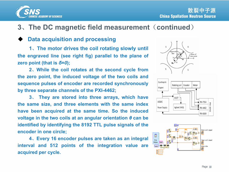
3、The DC magnetic field measurement(continued)Data acquisition and processing1、The motor drives the coil rotating slowly until
the engraved line (see right fig) parallel to the plane ofzero point (that is δ=0);
2、While the coil rotates at the second cycle fromthe zero point, the induced voltage of the two coils andsequence pulses of encoder are recorded synchronouslyby three separate channels of the PXI-4462;
3、 They are stored into three arrays, which havethe same size, and three elements with the same indexhave been acquired at the same time. So the inducedvoltage in the two coils at an angular orientation θ can beidentified by identifying the 8192 TTL pulse signals of theencoder in one circle;
4、Every 16 encoder pulses are taken as an integralinterval and 512 points of the integration value areacquired per cycle.
18
Page散裂中子源进展汇报 June 6, 2013
3、The DC magnetic field measurement(continued)
19
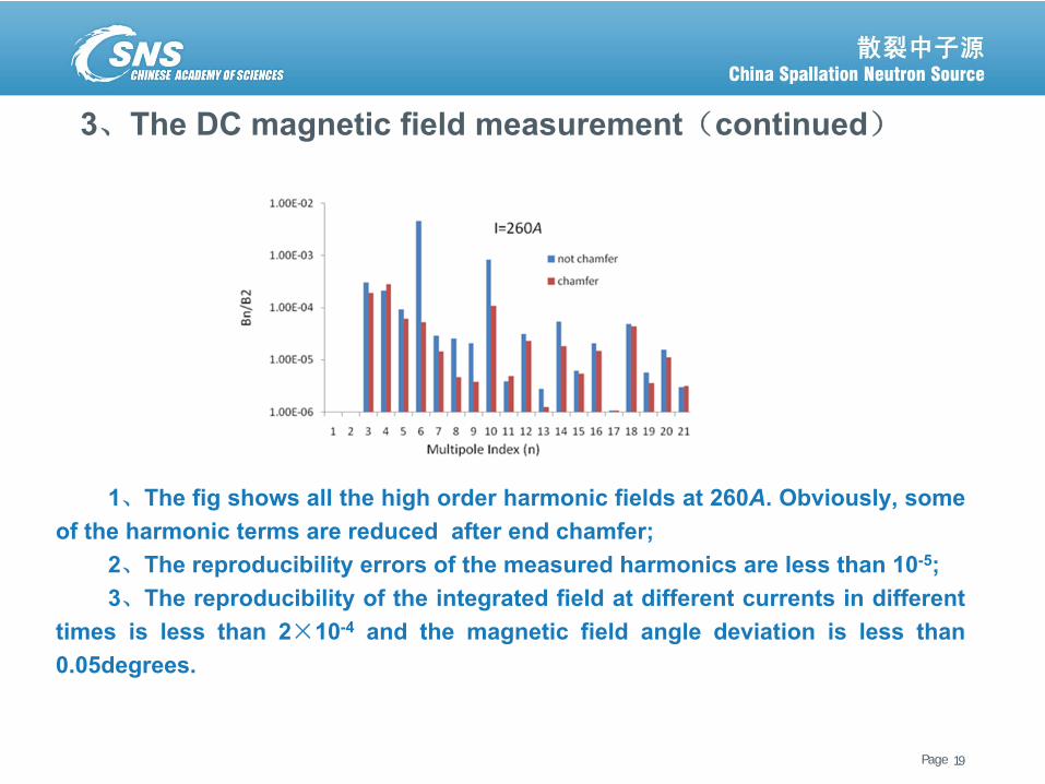
1、The fig shows all the high order harmonic fields at 260A. Obviously, someof the harmonic terms are reduced after end chamfer;
2、The reproducibility errors of the measured harmonics are less than 10-5;3、The reproducibility of the integrated field at different currents in different
times is less than 2×10⁻⁴ and the magnetic field angle deviation is less than0.05degrees.

Page散裂中子源进展汇报 June 6, 2013
4、The AC magnetic field measurement
20
Page散裂中子源进展汇报 June 6, 2013
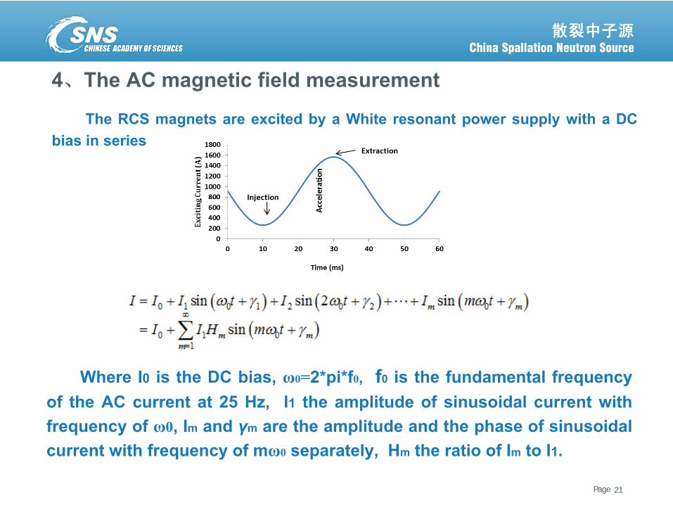
4、The AC magnetic field measurement
Where I0 is the DC bias, ω0=2*pi*f0, f0 is the fundamental frequencyof the AC current at 25 Hz, I1 the amplitude of sinusoidal current withfrequency of ω0, Im and γm are the amplitude and the phase of sinusoidalcurrent with frequency of mω0 separately, Hm the ratio of Im to I1.
21
The RCS magnets are excited by a White resonant power supply with a DCbias in series
Page散裂中子源进展汇报 June 6, 2013
4、The AC magnetic field measurement(continued)
22
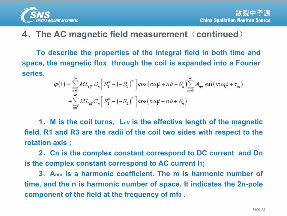
To describe the properties of the integral field in both time andspace, the magnetic flux through the coil is expanded into a Fourierseries.
1、M is the coil turns, Leff is the effective length of the magneticfield, R1 and R3 are the radii of the coil two sides with respect to therotation axis ;
2、Cn is the complex constant correspond to DC current and Dnis the complex constant correspond to AC current I1;
3、Anm is a harmonic coefficient. The m is harmonic number oftime, and the n is harmonic number of space. It indicates the 2n-polecomponent of the field at the frequency of mf0 .
Page散裂中子源进展汇报 June 6, 2013
4、The AC magnetic field measurement(continued)
23
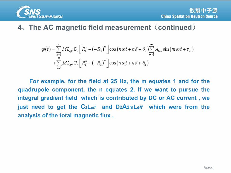
For example, for the field at 25 Hz, the m equates 1 and for thequadrupole component, the n equates 2. If we want to pursue theintegral gradient field which is contributed by DC or AC current , wejust need to get the C2Leff and D2A2mLeff which were from theanalysis of the total magnetic flux .
Page散裂中子源进展汇报 June 6, 2013
4、The AC magnetic field measurement(continued)
24
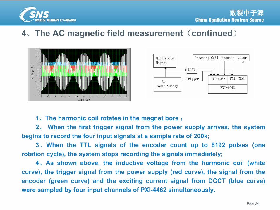
1、The harmonic coil rotates in the magnet bore ;
2、 When the first trigger signal from the power supply arrives, the systembegins to record the four input signals at a sample rate of 200k;
3、When the TTL signals of the encoder count up to 8192 pulses (onerotation cycle), the system stops recording the signals immediately;
4、As shown above, the inductive voltage from the harmonic coil (whitecurve), the trigger signal from the power supply (red curve), the signal from theencoder (green curve) and the exciting current signal from DCCT (blue curve)were sampled by four input channels of PXI-4462 simultaneously.
Page散裂中子源进展汇报 June 6, 2013
4、The AC magnetic field measurement(continued)
25
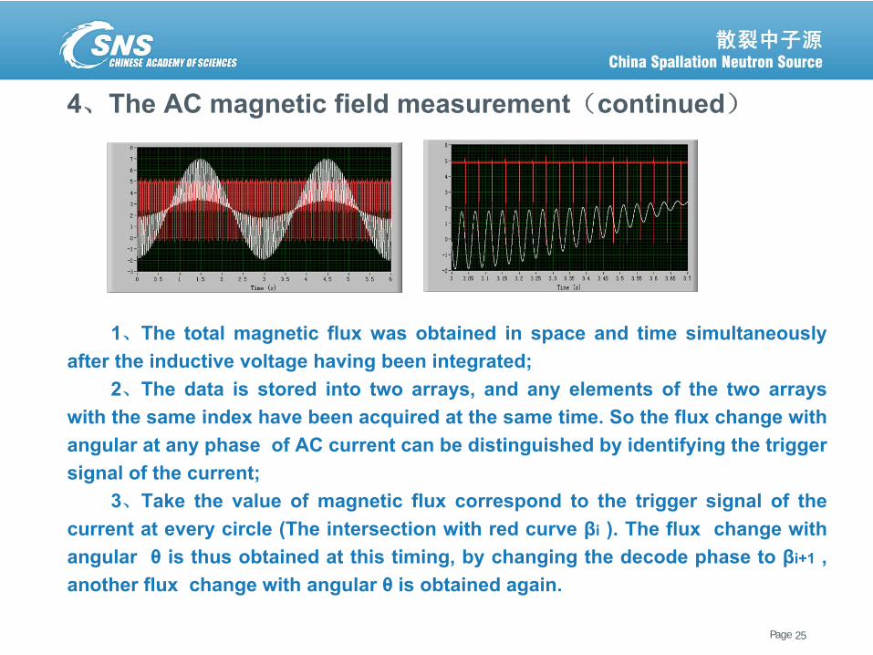
1、The total magnetic flux was obtained in space and time simultaneouslyafter the inductive voltage having been integrated;
2、The data is stored into two arrays, and any elements of the two arrayswith the same index have been acquired at the same time. So the flux change withangular at any phase of AC current can be distinguished by identifying the triggersignal of the current;
3、Take the value of magnetic flux correspond to the trigger signal of thecurrent at every circle (The intersection with red curve βi ). The flux change withangular θ is thus obtained at this timing, by changing the decode phase to βi+1 ,another flux change with angular θ is obtained again.
Page散裂中子源进展汇报 June 6, 2013
4、The AC magnetic field measurement(continued)
26
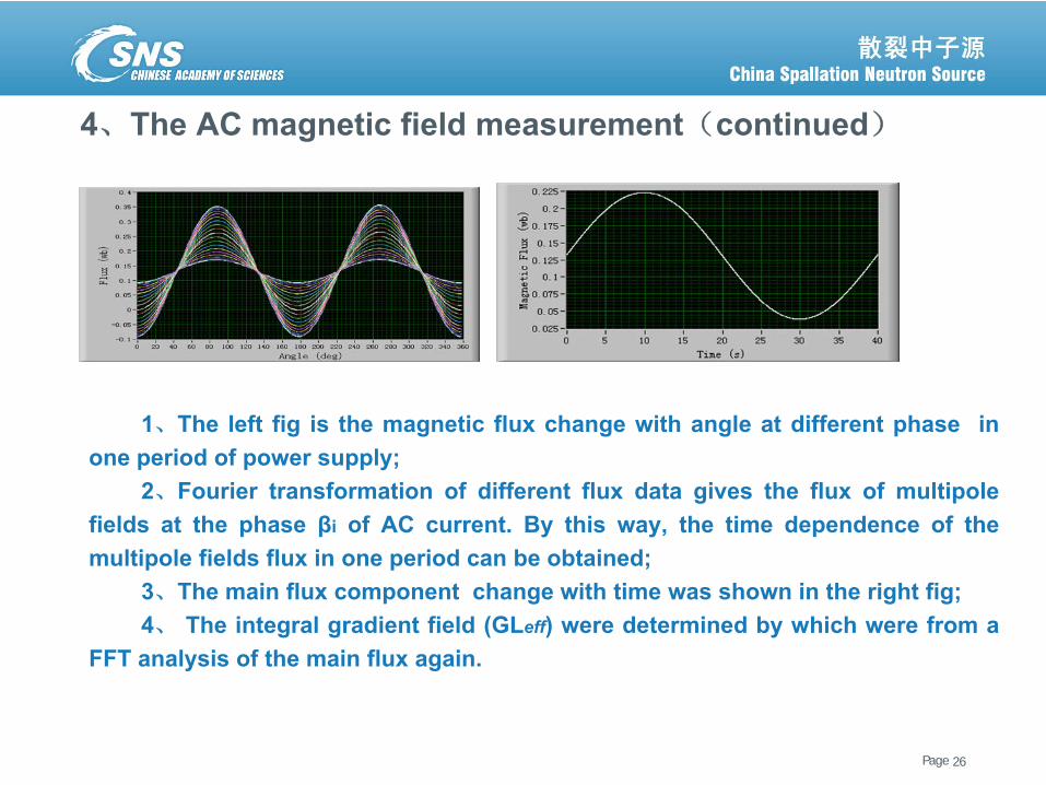
1、The left fig is the magnetic flux change with angle at different phase inone period of power supply;
2、Fourier transformation of different flux data gives the flux of multipolefields at the phase βi of AC current. By this way, the time dependence of themultipole fields flux in one period can be obtained;
3、The main flux component change with time was shown in the right fig;4、 The integral gradient field (GLeff) were determined by which were from a
FFT analysis of the main flux again.
Page散裂中子源进展汇报 June 6, 2013
4、The AC magnetic field measurement(continued)
27
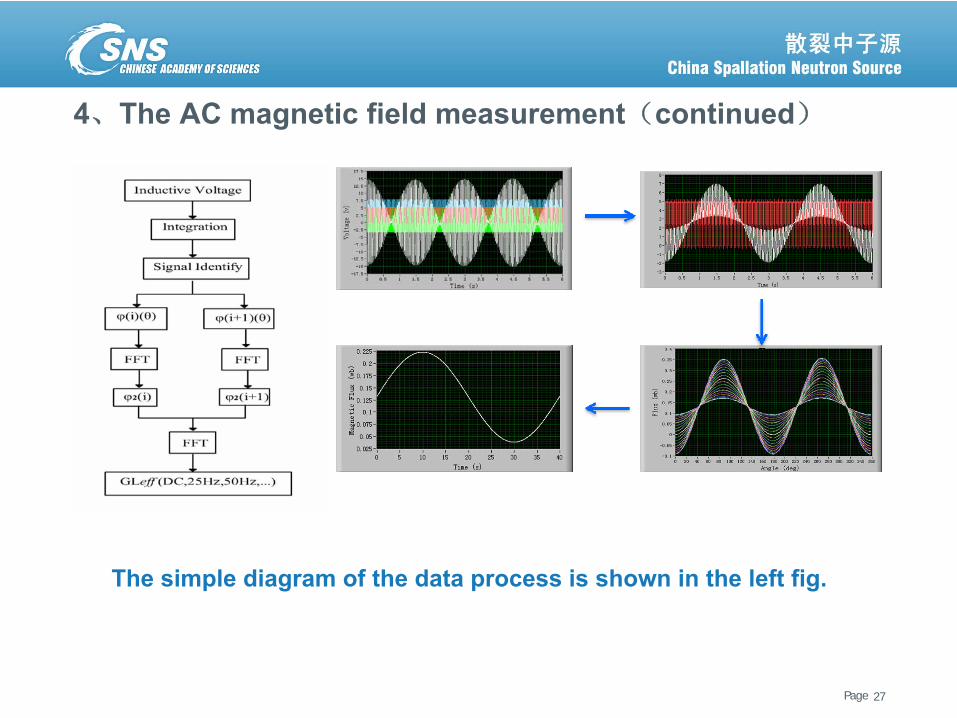
The simple diagram of the data process is shown in the left fig.
Page散裂中子源进展汇报 June 6, 2013
4、The AC magnetic field measurement(continued)
28
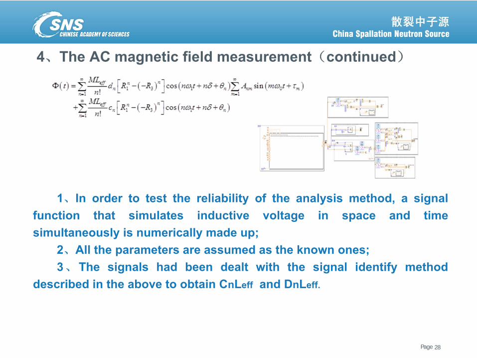
1、In order to test the reliability of the analysis method, a signalfunction that simulates inductive voltage in space and timesimultaneously is numerically made up;
2、All the parameters are assumed as the known ones;3、The signals had been dealt with the signal identify method
described in the above to obtain CnLeff and DnLeff.
Page散裂中子源进展汇报 June 6, 2013
4、The AC magnetic field measurement(continued)
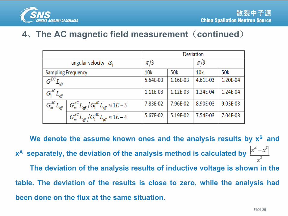
We denote the assume known ones and the analysis results by xS and
xA separately, the deviation of the analysis method is calculated by
The deviation of the analysis results of inductive voltage is shown in the
table. The deviation of the results is close to zero, while the analysis had
been done on the flux at the same situation.29
Page散裂中子源进展汇报 June 6, 2013
4、The AC magnetic field measurement(continued)
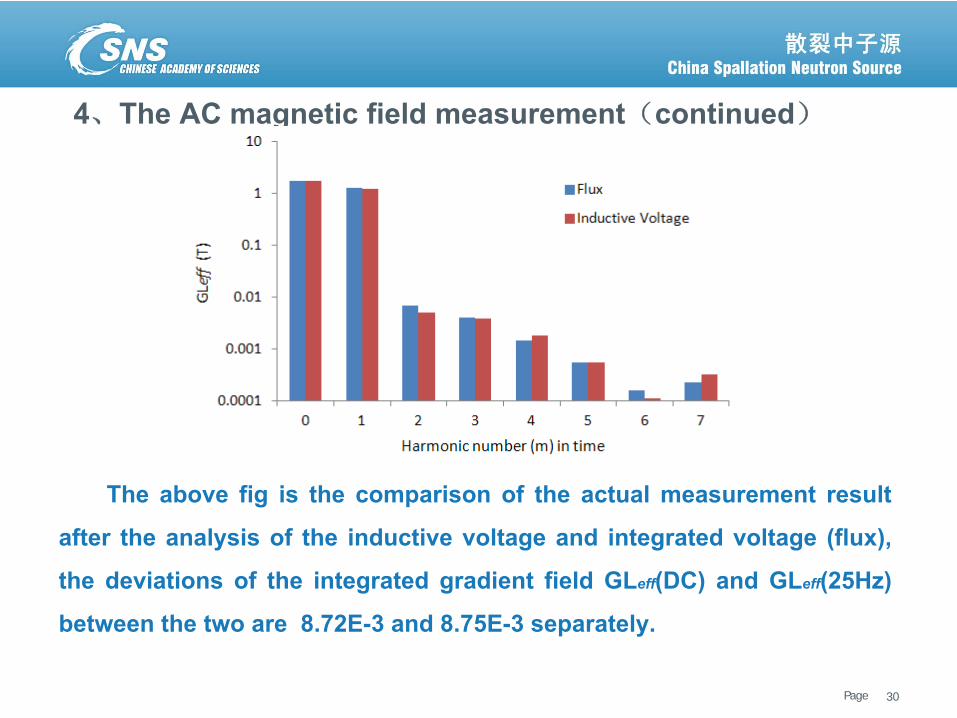
The above fig is the comparison of the actual measurement result
after the analysis of the inductive voltage and integrated voltage (flux),
the deviations of the integrated gradient field GLeff(DC) and GLeff(25Hz)
between the two are 8.72E-3 and 8.75E-3 separately.
30
Page散裂中子源进展汇报 June 6, 2013
4、The AC magnetic field measurement(continued)
31
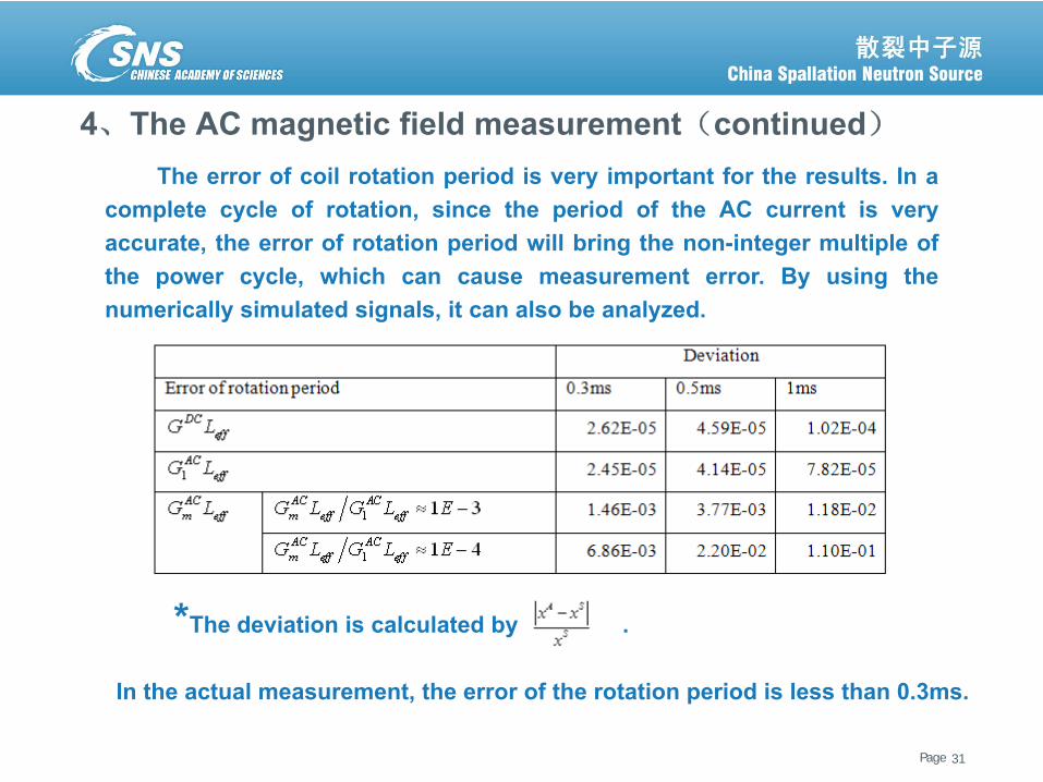
*The deviation is calculated by .
The error of coil rotation period is very important for the results. In acomplete cycle of rotation, since the period of the AC current is veryaccurate, the error of rotation period will bring the non-integer multiple ofthe power cycle, which can cause measurement error. By using thenumerically simulated signals, it can also be analyzed.
In the actual measurement, the error of the rotation period is less than 0.3ms.
Page散裂中子源进展汇报 June 6, 2013
4、The AC magnetic field measurement(continued)
32
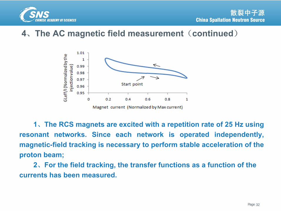
1、The RCS magnets are excited with a repetition rate of 25 Hz usingresonant networks. Since each network is operated independently,magnetic-field tracking is necessary to perform stable acceleration of theproton beam;
2、For the field tracking, the transfer functions as a function of the currents has been measured.
Page散裂中子源进展汇报 June 6, 2013
5、Conclusion
33
Page散裂中子源进展汇报 June 6, 2013
5、Conclusion
34
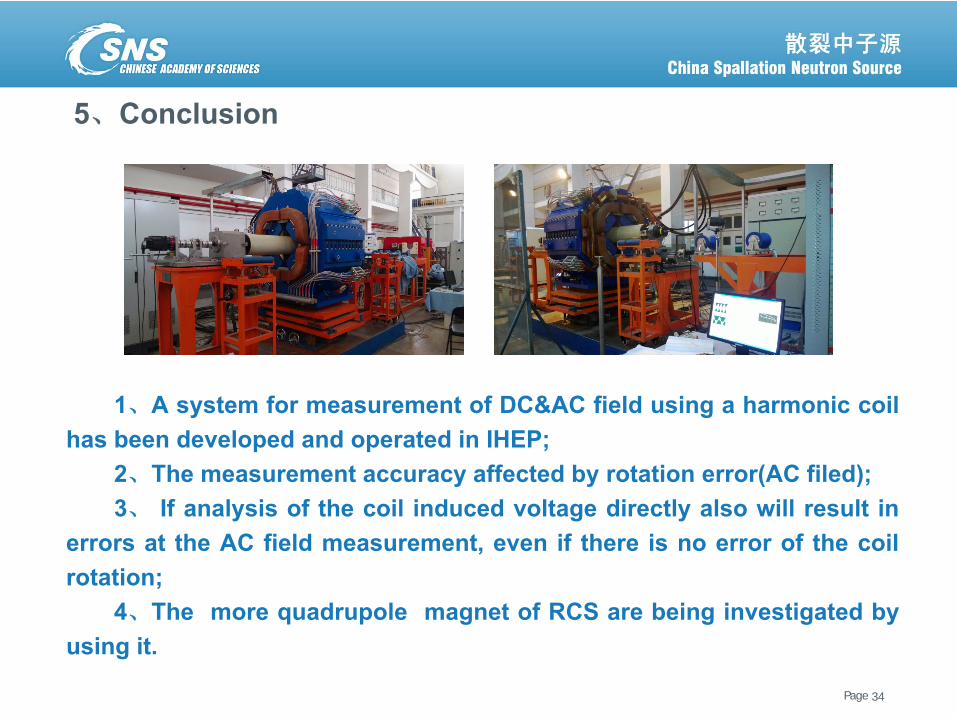
1、A system for measurement of DC&AC field using a harmonic coilhas been developed and operated in IHEP;
2、The measurement accuracy affected by rotation error(AC filed);3、 If analysis of the coil induced voltage directly also will result in
errors at the AC field measurement, even if there is no error of the coilrotation;
4、The more quadrupole magnet of RCS are being investigated byusing it.
Page散裂中子源进展汇报 June 6, 2013 35
Thank you for attentions!