design and construction of a post-tensioned t-girder ... · pdf filecorrugated steel web...
TRANSCRIPT

― ―49
Design and Construction of a Post-Tensioned T-Girder Bridge with Corrugated Steel Webs — Rebuilding of Mito Bridge —
ポストテンション方式波形鋼板ウェブ PCT 桁橋の設計・施工― 水戸橋架替え工事 ―
* ** *** ****
* Kiyoshi USUDA: P.S. Mitsubishi Construction Co., Ltd.臼田 清:(株)ピーエス三菱
** Katsumasa ISHIZAKI: P.S. Mitsubishi Construction Co., Ltd.石崎 克匡:(株)ピーエス三菱
*** Akihito ODAGIRI: Tokyo Metropolitan Government小田桐 皇仁:東京都
**** Shinsuke NISHINO: Tokyo Metropolitan Government西野 真介:東京都
Contact: [email protected]: corrugated steel web, prestressed concrete T-girder bridge, weight saving of superstructure,
girder depth restrictionDOI: 10.11474/JPCI.NR.2014.49
SynopsisThe Mito Bridge is located in Katsushika-ku, Tokyo, and crosses the class-A Ayase River. The bridge was recently rebuilt into a post-tensioned prestressed concrete (PC) T-girder bridge with corrugated steel webs. The design was determined in consideration of girder depth restriction and weight saving of the superstructure for reduced cost.This report describes the design and construction of the Mito Bridge which is the first post-tensioned corrugated steel web PC T-girder bridge built in Japan.
Structural DataStructure: Post-tensioned simple corrugated steel web
T-girder bridgeBridge Length: 39.700 mSpan: 38.700 mWidth: Carriageway: 6.00 m; sidewalk: 3.00 mOwner: Tokyo Metropolitan GovernmentDesigner: Chuoh Consultants Co., Ltd.Contractor: P.S. Mitsubishi Construction Co., Ltd.Construction Period: Aug. 2009 – Nov. 2010Location: Tokyo, Japan
1. IntroductionThe Mito Bridge is a road bridge crossing the class-A Ayase River in the Tone River system in Katsushika-ku, Tokyo. The road is known as historic Mito Kaido which served as one of the trunk roads together with the
five major highways called Gokaido during the early modern Edo period. The existing bridge was interfering with the design revetment height of the river, and its left bank abutment was protruding into the river and disturbing the flow of water. It was decided to rebuild it for solving these problems. The new bridge was required to meet girder depth restrictions and be light in weight. With these requirements and economic efficiency taken into account, corrugated steel web PC T-girder was adopted for the new bridge. This type of structure has been used for pre-tensioned bridges, but has not been applied to a post-tensioned bridge before. In order to ensure quality and safety, it was necessary to consider various design factors and prepare detailed plans for girder manufacture and bridge construction.This report describes the design and construction of the Mito Bridge which is the first post-tensioned corrugated
Table 1 Materials used
Concrete σck = 60 N/mm2
Prestressing steel strands
Longitudinal SWPR7BL 12S12.7B
TransverseSWPR19L 1S28.6 ctc500 (carriageway)SWPR19L 1S17.8 ctc500 (sidewalk)
Corrugated steel sheets SM490
t = 16 mm (carriageway)t = 12 mm (sidewalk)
ConnectionUpper and lower flanges Embedding
Corrugated steel sheets Double shear connection using high tension bolts
― ―50
steel web PC T-girder bridge built in Japan.
2. DesignTable 1 shows the materials used for the bridge. Fig. 1 shows the structural overview, and Fig. 2 shows the girder cross sections.
(1) Consideration to Shear Bearing RatioPrestressing tendons in post-tensioned T-girders are bent upward from the midspan toward the supports. Since the corrugated steel webs in this bridge could not accommodate the tendons, the thickness of the lower flange needed to be increased to follow the bend. As a result, the ratio of the corrugated steel web in the main girder cross section decreased toward the girder ends, and the ratio of the upper and lower flanges increased in turn. Corrugated steel web bridges are usually designed with all shear force assigned to the corrugated steel sheets. In this bridge, however, this assumption could affect the safety margin for the concrete flanges where the thickness was increased. Therefore, the authors calculated shear bearing ratios of the upper and lower flanges and corrugated steel sheets for the areas with the increased lower flange thickness, and made shear verification for the concrete flanges as well as for the corrugated steel webs.
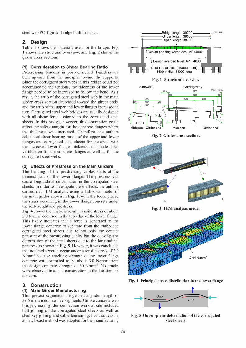
(2) Effects of Prestress on the Main GirdersThe bending of the prestressing cables starts at the thinnest part of the lower flange. The prestress can cause longitudinal deformation in the corrugated steel sheets. In order to investigate these effects, the authors carried out FEM analysis using a half-span model of the main girder shown in Fig. 3, with the focus placed the stress occurring in the lower flange concrete under the self-weight and prestress.Fig. 4 shows the analysis result. Tensile stress of about 2.0 N/mm2 occurred in the top edge of the lower flange. This likely indicates that a force is generated in the lower flange concrete to separate from the embedded corrugated steel sheets due to not only the contact pressure of the prestressing cables but the out-of-plane deformation of the steel sheets due to the longitudinal prestress as shown in Fig. 5. However, it was concluded that no cracks would occur under a tensile stress of 2.0 N/mm2 because cracking strength of the lower flange concrete was estimated to be about 3.0 N/mm2 from the design concrete strength of 60 N/mm2. No cracks were observed in actual construction at the locations in concern.
3. Construction(1) Main Girder ManufacturingThis precast segmental bridge had a girder length of 39.5 m divided into five segments. Unlike concrete web bridges, main girder connection work at site included bolt joining of the corrugated steel sheets as well as steel key joining and cable tensioning. For that reason, a match-cast method was adopted for the manufacturing
Fig. 1 Structural overview
↓ Design riverbed level: AP-4000
Bridge length: 39700 Girder length: 39500 Span length: 38700
↑ Design ponding water level: AP+4000
Cast-in-situ piles (15/abutment) 1500 in dia., 41000 long
Unit : mm
Fig. 2 Girder cross sections
>部端桁<>央中間支<
<車道部>
6000
25002500
600
1900
3000400
1000
1150
7200
600
400
3800
1000
101
3
<桁端部><支間中央>
<歩道部>
1400 19
00
Sidewalk Carriageway
Girder endMidspan Midspan Girder end
Unit : mm
Fig. 3 FEM analysis model
Fig. 4 Principal stress distribution in the lower flange
2.04 N/mm2
Fig. 5 Out-of-plane deformation of the corrugated steel sheets
Gap Gap

― ―51
of the main girders to make the conditions during manufacture as equal as possible to those during connection at site. The odd-numbered segments (1, 3 and 5) were cast first, and, using their end surfaces as formwork, the even-numbered segments (2 and 4) were cast.The corrugated steel web materials were manufactured at a separate steel sheet maker, and the precision of manufacture of the steel sheets was expected to influence the work efficiency at site during the main girder connection. In order to minimize problems, situation at site during connection was simulated during the main girder manufacture at the factory as shown in Fig. 6. As a result, no problems like bolt hole misalignment occurred during on-site connection of the segments.High compressive stress normally occurs in the lower flange of a corrugated steel web PC T-girder bridge immediately after tensioning. The use of match-cast method was considered effective also in terms of prevention of edge chipping and cracks in the connected surfaces which were under an estimated compressive stress of about 22 N/mm2.
(2) TensioningThe longitudinal cables of a corrugated steel web PC T-girder bridge have a laterally eccentric arrangement in the lower flange to avoid the web at the center. Fig. 7 shows the arrangements of the six cables (12S12.7B) in this bridge. Taking the low lateral rigidity of the corrugated steel web structure into account, the cables were tensioned symmetrically and simultaneously at both ends using four jacks to prevent eccentric force from acting on the cross section during tensioning (Fig. 8). The lateral spacings of the cable anchors need to be determined to allow for simultaneous use of two jacks.
(3) Bolt ConnectionThe segment joints were bolt connected after tensioning the first two of six cables. This was an attempt to prevent cambering of the main girder during tensioning of the second pair of cables. The shear force due to loads such as prestress and main girder self-weight was successfully carried by the corrugated steel sheets as assumed in the design.
(4) Main Girder ErectionFig. 9 shows erection of a main girder, and Fig. 10 shows the schematic of the erection operation.The bridge was close to the Metropolitan Expressway on the left bank and a residential area on the right bank. Work space for girder erection was limited to a temporary pier which was built in the river. Therefore, an erection girder and rails were installed at the back of the abutments for lifting and moving the main girders to the positions.The main girder erection was completed in a period of ten days, with one day for conveying, positioning and connecting the segments and tensioning the cables, and
Fig. 6 Main girder manufacturing
Fig. 7 Prestressing steel arrangements
330
330
240
350
Midspan Girder end
Unit : mmPrestressing
Steel
Fig. 8 Cable tensioning
Fig. 9 Main girder erection

― ―52
概 要 本工事は,東京都葛飾区に位置する一級河川綾瀬川に架かる水戸橋の架替え工事である。新しい橋には桁高
制限への対応と同時に軽量化も可能となり,経済性に優れるという理由から,ポストテンション方式の波形鋼
板ウェブ PCT 桁橋(コルティー工法)が採用された。本橋梁形式はこれまでにプレテンション方式の施工実
績はあったものの,ポストテンション方式は我が国で初の施工となるものである。このことから,設計および
施工においては種々の設計的検討や綿密なけた製作および施工計画を行い,品質と安全の確保に十分配慮する
必要があった。
本報告は,我が国初の波形鋼板ウェブ PCT 桁橋である水戸橋の設計および施工について報告するものである。
one day for lateral transfer and erection of the girder for each of total five main girders.
ConclusionThe bridge was completed in November 2010 (Fig. 11). It was very significant that the first post-tensioned corrugated steel web T-girder bridge was constructed successfully, with various factors taken into account at each process of design, manufacture and erection. The
authors hope this report would be of help for increased application of this type of bridge structure in future.
References[1] Adachi, K. et al.: Design and Construction of the Post-Tensioned T-Girder Bridge using Corrugated Steel Web–Rebuilding Construction of Mito Bridge–, Journal of Prestressed Concrete, Vol. 54, No. 1, JPCI, Tokyo, pp. 33-39, Jan. 2012 (in Japanese)
Fig. 10 Schematic of main girder erection
Fig. 11 Completion of the bridge