design status of the demo-fns steady state tokamak in rf · 2015-10-07 · demo-fns background •...
TRANSCRIPT

Kurchatov Nuclear Technology ComplexMoscow, 123182, Russia
B.V. Kuteev E.A. Azizov, P.N. Alexeev, S.S. Anan’ev, V.M.Chernov, B.K. Chukbar, A.S. Bykov, A.A. Frolov, A.A. Golikov, A.V. Golubeva, P.R. Goncharov, M.P. Gryaznevich, M.I. Gurevich, A.Yu. Dnestrovskij, A.A. Dudnikov, D.P. Ivanov, R.R. Khairutdinov, V.I. Khripunov, A.A. Klischenko, B.N. Kolbasov, А.I. Krylov, V.E. Lukash, V.V. Lukyanov, S.Yu. Medvedev, A.A. Morozov, A.A. Panasenkov, V.S. Petrov, P.V. Savrukhin, A.A. Sedov, V.Yu. Sergeev, E.V. Shestakov, A.B. Sivak, A.V. Spitsyn, S.A. Subbotin, A.L. Shimkevich, Yu.S. Shpanski, V.P. Tsibulskiy, A.V. Zhirkin
e-mail: [email protected]
Collaborators: Efremov Institute, Dollezhal Institute, AtomProject, Bochvar Institute, Polytechnic University, CTF-Centre
Design status of the DEMO-FNS Steady State Tokamak in RF
B.V. Kuteev et al., IAEA SSO-8, 26-29 May 2015, Nara, Japan
NATIONAL RESEARCH CENTER KURCHATOV INSTITUTE
НАЦИОНАЛЬНЫЙ ИССЛЕДОВАТЕЛЬСКИЙ ЦЕНТР «КУРЧАТОВСКИЙ ИНСТИТУТ»

DEMO-FNS background• DEMO-FNS tokamak device is the key facility in the
hybrid branch of the Russian fusion program. • The construction of DEMO-FNS is planned by 2023. This
facility should provide the choice of steady state operation regimes, tests of materials and components, demonstration of tokamak enabling technologies and molten salt nuclear technologies of hybrid blanket and radiochemical plant for Pilot Hybrid Plant (PHP).
• The PHP construction is planned by 2030. Design targets are 40 MW for the fusion power, 500 MW for the total thermal power and 200 MW for the electric power that should provide engineering Qeng ~ 1 (self-sufficiency).

Strategy 2013 for Fusion‐Fission development in RussiaE. Velikhov, IAEA FEC‐25, O‐3
B.Kuteev et al. NF, 55 (2015) accepted
2015 2030 2050
T-15 ITER DEMO PROTO
DEMO‐FNS
Test beds for enabling
technologies
PHP
Test beds for molten salt technologies
Burning Plasma Physics
Nuclear physics and technology
Nuclear technologies of new generation
Hybrid Fusion

Major facilities on the path to Industrial Hybrid Plant
• Magnetic system• Vacuum chamber• Divertor• Blanket• Remote handling• Heating and current
drive• Fuelling and
pumping• Diadnostics• Safety• Molten salts
Pilot Hybrid Plant construction by 2030 P=500 MWt, Qeng ~1
Steady State Technologies
•Materials
SSO&MS Globus-M3 FNS-ST DEMO-FNSDT neutrons MS blankets
Industrial Hybrid Plant construction by 2040 P=3 GWt, Qeng ~6.5 P=1.3 GWe, P=1.1 GWn, MA=1t/a, FN=1.1 t/a
•Hybrid Tech•Integration
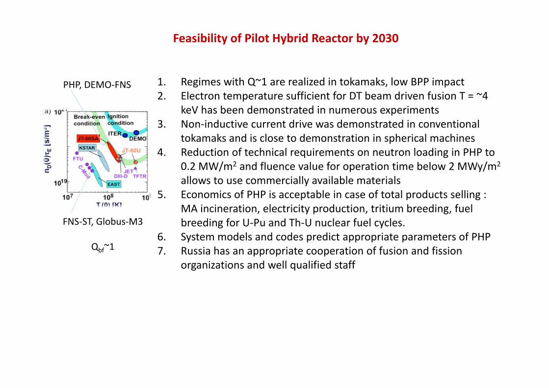
Feasibility of Pilot Hybrid Reactor by 2030
1. Regimes with Q~1 are realized in tokamaks, low BPP impact2. Electron temperature sufficient for DT beam driven fusion T = ~4
keV has been demonstrated in numerous experiments3. Non‐inductive current drive was demonstrated in conventional
tokamaks and is close to demonstration in spherical machines4. Reduction of technical requirements on neutron loading in PHP to
0.2 MW/m2 and fluence value for operation time below 2 MWy/m2
allows to use commercially available materials5. Economics of PHP is acceptable in case of total products selling :
MA incineration, electricity production, tritium breeding, fuel breeding for U‐Pu and Th‐U nuclear fuel cycles.
6. System models and codes predict appropriate parameters of PHP7. Russia has an appropriate cooperation of fusion and fission
organizations and well qualified staff
PHP, DEMO‐FNS
FNS‐ST, Globus‐M3
Qbf~1

Construction Risks for Pilot Hybrid Plant
1. Low design level for Hybrid systems (conceptual or pre‐conceptual)2. Enabling Technologies for tokamak Steady State Operation need
substantial resource upgrade (from minutes to ~5000 hours)3. Additional R@D are mandatory for fusion nuclear science and
technology4. Molten salt nuclear technology of hybrid blanket and radio‐chemical
system require demonstration5. Lack of information on tokamak operation under high plasma loadings,
noninductive current drive and non‐equiliblium plasmas 6. Poor database on radiation damage of materials in 14 MeV neutron
spectra7. Challenging choice of materials and molten salt compositions is
foreseen8. Licensing delays and Atomic Energy Law update
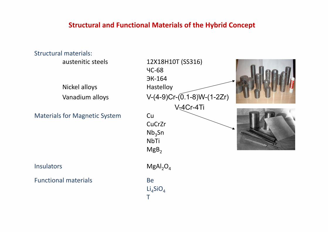
Structural and Functional Materials of the Hybrid Concept
Structural materials:austenitic steels 12Х18Н10Т (SS316)
ЧC‐68ЭК‐164
Nickel alloys HastelloyVanadium alloys V-(4-9)Cr-(0.1-8)W-(1-2Zr)
V-4Cr-4TiMaterials for Magnetic System Cu
CuCrZrNb3SnNbTiMgB2
Insulators MgAl2O4
Functional materials BeLi4SiO4T


DEMO-FNS Features
• DEMO-FNS has a superconducting magnetic system utilizing low temperature superconductors Nb3Sn and NbTi
• The steady state operating device has the major radius R =2.5-2.7 m and the minor radius a =1 m, toroidal magnetic field B = 5 T, plasma current Ip = 5 MA, neutral beam heating and current drive system with the total power of 30 MW and 6 MW of gyrotron power at 170 GHz
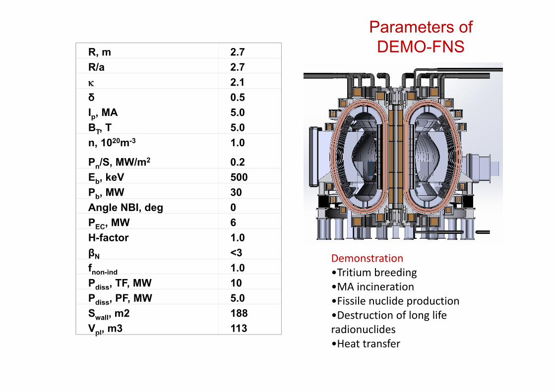
Parameters of DEMO-FNS
Demonstration•Tritium breeding•MA incineration•Fissile nuclide production•Destruction of long life radionuclides•Heat transfer
R, m 2.7R/a 2.7 2.1δ 0.5Ip, MA 5.0BT, T 5.0n, 1020m-3 1.0
Pn/S, MW/m2 0.2Eb, keV 500Pb, MW 30Angle NBI, deg 0PEC, MW 6H-factor 1.0βN <3fnon-ind 1.0Pdiss, TF, MW 10Pdiss, PF, MW 5.0Swall, m2 188Vpl, m3 113

FNS-ST, DEMO-FNS and ITER parameters
FNS-ST DEMO-FNS ITER
Major radius R, m 0.5 2.75 6.2
DT-fusion option Beam driven fusion
Beam driven and thermonuclear fusion
Thermonuclear fusion
Heat transfer from alphas to plasma no yes small yes BPP valuable
Divertor configuration DN DN SN
Toroidal field at the VV center, T 1.5 5 5.3
Fusion power, MW 1 - 3 30 - 40 500
Auxiliary heating power PAUX, MW ~ 8 - 10 30 - 40 50 - 70
Fusion energy gain factor Q ~ 0.2 ~ 1 ~ 10
Shielding at high field side, m Без защиты ~ 50 cm 60 – 80cm
Type of magnetic system CuCrZr LTS LTS
Neutron loading Гn, MW/m2 0.2 0.2 0.5
Neutron fluence at lifetime, MWy/m2 ~ 2 (*) ~ 2 0.3
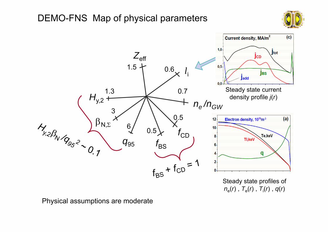
DEMO-FNS Map of physical parameters
Hy,2
q95
N,
1.5
1.3
3
6
Zeff
li
fBS
fCD
0.6
0.5
0.7
ne /nGW
0.5
Steady state current density profile j(r)
Steady state profiles of ne(r) , Te(r) , Ti(r) , q(r)
Physical assumptions are moderate

Steady State free boundary equilibrium magnetic configuration
DEMO-FNS Basic plasma configuration

Breakdown in DEMO-FNS
0 200 400 600-600
-400
-200
0
200
400
600VNS-SC FIELD NULL
R [cm]
Z [c
m]
0 200 400-1
0
1
2x 10
5
R [cm]
Bz
[G]
0 200 4000
5
10
15
R [cm]
psi [
Vs]
0 10 VsBZ max 12 T
R, cm Z, cm R, cm
Z, cm I, MA*t
PF1_U 125 460 30 30 0.2
PF1_L 125 -460 30 30 0.2
PF2_U 175 480 35 35 0.34
PF2_L 175 -480 35 35 0.34
PF3_U 310 495 50 50 0.69
PF3_L 310 -495 50 50 0.69
PF4_U 400 445 30 30 0.96
PF4_L 400 -445 30 30 0.96
PF5_U 495 360 55 55 0.68
PF5_L 495 -360 55 55 0.68
PF6_U 535 255 30 30 -0.5
PF6_L 535 -255 30 30 -0.5
CSU1 42.5 280 15 76 -13.7
CSU2 42.5 160 15 158 40.4
CS1 42.5 0 15 160 14.0
CSL2 42.5 -160 15 158 40.4
CSL1 42.5 -280 15 76 -13.7

Current generation and fusion power in DEMO-FNS
0,0 0,2 0,4 0,6 0,8 1,0 1,2 1,4
10
100
Pt150dfn
Pt500dfn
Pd150tfn
Pd500tfn
Pmaxwellfn
Ptotalfn
MW
n20, m-3
Fusion power and components (beam plasma fusion + thermonuclear) versus plasma density
0,0 0,2 0,4 0,6 0,8 1,0 1,2 1,40
1
2
3
4
5
6
7
8
INBCD (Et=500 keV)
INBCD (Ed=500 keV)IBS
IpMA
n20, m-3
Current and its components versus plasma density
System codes suggest reaching design parameters of DEMO-FNS and the neutron loading that is higher than 0.2 MW/m2

DEMO-FNS magnet system details
• The magnetic coil system consists of 18toroidal coils, 12 poloidal coils, 2 verticalcontrol coils and 18 RMP correcting coils
• The partitioned central solenoid (CS) hasthe flux storage of 8 Wb increased bypoloidal coils up to 20 Wb that is sufficientfor plasma formation and the current rumpup to 5 MA during 2 seconds
• Peripheral parts of the CS are used forshaping the magnetic configuration

Toroidal field coils
Number of toroidal field coils NTF = 18Two loops Nb3Sn+NbTiTotal TFC current ITF = 70 MA-turnsTFC magnetic energy WTF = 6 GJ
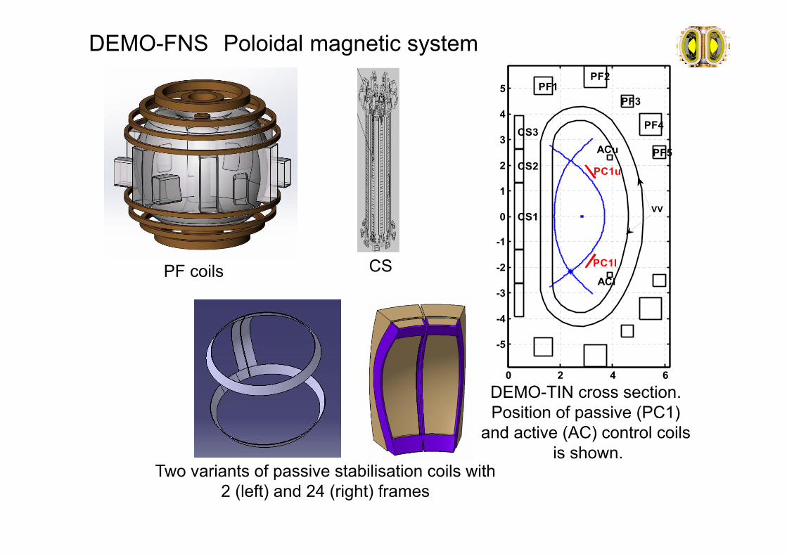
DEMO-FNS Poloidal magnetic system
PF coils CS
PF1PF2
PF3
PF4
PF5
CS3
CS2
CS1
ACu
PC1u
PC1l
ACl
0 2 4 6
-5
-4
-3
-2
-1
0
1
2
3
4
5
VV
DEMO-TIN cross section.Position of passive (PC1)
and active (AC) control coilsis shown.
Two variants of passive stabilisation coils with 2 (left) and 24 (right) frames

General layout of DEMO-FNS
TF coil cross section
Equatorial section of DEMO-FNS
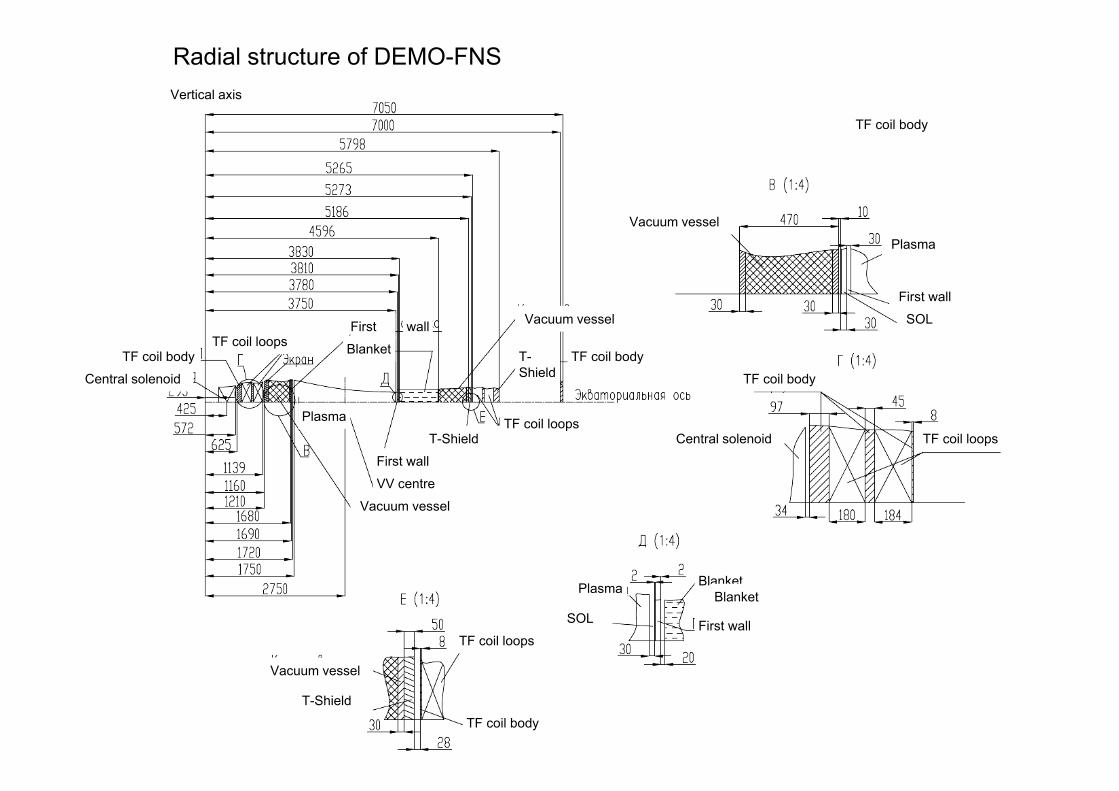
Radial structure of DEMO-FNS
Vacuum vessel
Plasma
First wall
SOL
TF coil body
TF coil body
TF coil loopsCentral solenoid
Blanket
First wallSOL
Plasma
Vertical axis
TF coil bodyTF coil loops Blanket
wallFirst
TF coil body
Vacuum vessel
Plasma
Vacuum vessel
First wall
VV centre
T-Shield
T-Shield
Blanket
TF coil loops
TF coil loops
TF coil body
Vacuum vessel
T-Shield
Central solenoid

DEMO-FNS vacuum vessel details
• The vacuum vessel (VV) is made of austeniticstainless steel (SS) with the shell thickness of 3cm and the 2 cm bulkheads (ribs)
• The volume of the VV is filled with 70% SS and30 % water for neurton&gamma shielding
• The VV thickness is 50 cm at the high field side(HFS) and 60 cm at the LFS and divertor regions
• The VV acts as a radiation shield of themagnetic system reducing the radiation heatingbelow 1 mW/cm-3

DEMO-FNS Vacuum vessel (VV)
Blanket segmentation
VV sector (outside)
VV sector (inside)
Shield between two shells of VV

Electronic mockup of VV
Distribution of EM pressure for upward disruption accident
VV shell VV ribs
VV shell under 40 bars of internal pressure

VV cooling system
VV structure at high field side
Temperature fields under normal operation
VV shellVV shell
Neutron shield unit
Neutron shield unit
Input collector
Heat exchanger 1
Heat exchanger 2
Pump1
Pump2
Circuit1
Circuit2
DEMO-FNS divertor details
• The divertor has a double null magneticconfiguration with a strong shaping ( up to0.5) and Iong outer legs (L~0.5R)
• Divertor is capable of operating under heatloading up to 10 MW/m2
• Lithium technologies including dust injectionare used for the edge plasma control andprotection of the plasma facing componentsfrom erosion
• Remote handling concept assumes repairprocedures and changing the divertorcassettes through equatorial ports
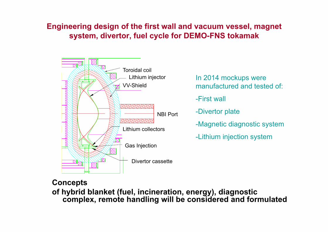
Engineering design of the first wall and vacuum vessel, magnet system, divertor, fuel cycle for DEMO-FNS tokamak
Concepts of hybrid blanket (fuel, incineration, energy), diagnostic
complex, remote handling will be considered and formulated
In 2014 mockups were manufactured and tested of:
-First wall
-Divertor plate
-Magnetic diagnostic system
-Lithium injection system
Toroidal coilLithium injector
VV-Shield
Lithium collectors
NBI Port
Gas Injection
Divertor cassette

DEMO-FNS Divertor
Divertor plates Procedure of divertor module removing through equatorial port
See in more details I.V.Mazul presentation In-vessel components development from ITER to DEMO, IAEA DEMO-3 technical meeting, Hefei, China

DEMO-FNS blanket details
• The tokamak design reserves a place for hybridblankets of different styles with 76 cm thicknessand 4 m height at the low field equatorial zone
• Energy production, fissile nuclide and tritiumbreeding, transmutation technologies should bedemonstrated by hybrid blankets
• Molten salts will be tested as the basic option forfuel mixture and coolant (now H2O is first)
• The blanket modules are replaceable• Blanket module maintenance is fulfilled using
transfer in the major radial direction through 6equatorial ports (toroidal shifts for CB neighbors)

DEMO-FNS Blanket
Blanket : 24 sections of different functions
- processing of wasted nuclear fuel;- tritium breeding;-sections for U-blanket testing;- sections with ports for arrangement of plasmaauxiliary heating testing (antennas and waveguidesfor high-frequency systems and elements of NBIbeam ducts);- diagnostical equipment.Each section includes stationary part (iron-watershield) and removing part. Vacuum boundary isformed on surface of stationary shield.
Blanket segmentation
Blanket position

U-Pu
1Pu+1T per 1n(DT)
Th-U
0.6U+1T per 1n(DT)
Hear exchanger, primary loop
Hear exchanger, secondary loop
Heat transfer
Molten salt85% FLiNaK+15% ThF4580ºС 5.86 kg/s
550ºС1 bar
Molten salt92% NaBF4+8% NaF 539ºС
480ºС1.7 kg/s
140ºС10 bar
water20ºС
Molten salt blanket module Thermal power 175 kW
Primary loop
Secondary loop
Cooler
Drain vessel
Storage
pump
Solid blanket module
Two fuel cycles considered with molten salt blankets

DEMO-FNS heating system details
• Plasma heating and current drive is provided by 6injectors with the unit power of 7.5 MW each andthe neutral energy of up to 500 keV
• In operating conditions four of them are in theactive mode, one is sequentially regenerated andone is in reserve for the ion source exchange andmaintenance procedures
• Injectors operate on a 50:50 mixture of deuteriumand tritium /Option of operating on D only isexplored as well that reduces the tritium inventory
• Six gyrotrons have the power of 1 MW each andthe frequency of 170 GHz. There is also a reservechannel to support maintenance and scheduledrepairs during the device operation.

DEMO-FNS fueling system details
• The DENO-FNS is equipped with a large scalefuelling system with deuterium-tritium mixture
• The gas injection rate may reach 1023 atoms persecond
• The mixture composition 50:50 percent ismaintained by cleaning out impurities includinghelium and balancing the losses of deuterium andtritium caused by the fusion reactions
• High vacuum pumping from divertor of the deviceis provided by cryogenic pumps with sequentialregeneration (up to 24 vertical ports)

DEMO-FNS safety&radiochemical systems
• The facility is equipped with detritiation systems for water and gases. The total tritium amount on site is evaluated as ~2 kg during the operation campaign. Less than 100 grams are expected in the vacuum vessel
• Radiochemical plant supports preparation of the molten salt mixture, technological procedures for the nuclides feeding and extraction in continuous regime and their utilization.
• The molten salts are used as nuclear fuel mixtures and the first loop coolants on the site.
• The technologies for tritium breeding and extraction will be developed within DEMO-FNS project

Tritium technologies: concept and requirements
1 – divertor pump; 2 – NBI pump; 3 – VV&FW; 4 - blanket; 5 – membrane purification system; 6– T-bed; 7 - Hydrogen compounds catalytic decomposition system; 8 – Super-heavy waterwaste recycling system; 9 - Hydrogen isotopes separation system; 10 - Gas puff system; 11 -Pellet-injection system; 12 - NBI system; 14 – plasma

Tritium technologies: optimization
code “TC-FNS” was developed to estimate the distribution of tritium in the systems of a fusion facility and elements of "tritium plant”.
FNS system NBI (D-only), (g) NBI (D:T=1:1),(g)
Neutral Beam Injection system 7 44Divertor pumping and fuel injector systems 27 17Cryotraps and membrane gas purification system 27 27Hydrogen isotopes long-term storage system (getters) 116 178Isotopes separation system 81 198Hydrogen compounds catalytic decomposition system 41 100Hydrogen isotopes long-term storage system (getters)
92 225Recycling of super heavy water waste system Pipelines, receivers, pumps, etc. 102 102Tokamak plasma 0,03 0,03TOTAL 492 890tritium burnup, per year 1780 1797
Use of fuel ratio of the mixture to 50% D-50% T
for all systems
H‐isotope separation system is required for protium removal only →a smaller amount of tritium on site
But NBI system is the most significant consumer of fuel

Schematic of DEMO-FNS building(2023)
Demonstration of hybrid technologies
• Tritium breeding, • Fissile nuclides,• Incineration of ling
life radionuclides• Heat transfer
technologies
Fusion power 40 MW Subcritical fission power up to 500 MW

DEMO-FNS Site

DEMO-FNS Physics& Technology
• The current level of the design corresponds to conceptual one. The engineering design stage will be completed in 2015 for a simplified water coolant option
• We have started manufacturing of mockups for VV, divertor, diagnostics of SS magnetic fields
• This project is realized in collaboration of Kurchatov institute with public corporations NIIEFA, NIKIET, ATOMPROJECT (VNIPIET), VNIINM, SPb Polytechnic University and CTF-Center

Mass of magnets and vacuum vessel
Subsystem mass, ton• Magnets
Toroidal coils (LTS, Cu, insulation, SS-bodies) 770Poloidal coils (LTS, Cu, insulation, SS-bodies) 660Central solenoid (LTS, Cu, insulation, SS-bodies) 60Inter-coil and enforcement structures and supports 130
• Total magnet system 1620
• Vacuum vessel with in-vessel componentsVacuum vessel 630Radiation Shield 1500Blanket 500
• Total Vacuum vessel with in-vessel components 2630• Total MS+VV 4250
• Total Power consumption 150-200 MWNBI 100—120 MW, Cryogenics~20 MW, other 30—60 MW.
• Peak power at the initiation stage ~400 MW

Conclusions• R&D programme and roadmap have been proposed to
create Pilot Hybrid Plant (PHP) in Russia on basis of tokamak and molten salt technologies by 2030
• The engineering design of the DEMO-FNS device for demonstration of hybrid and molten salt technologies has been started in collaboration with Rosatom public organizations and universities to be completed in 2015
• Modeling of steady state regimes and scenarios suggest technical feasibility of DEMO-FNS and PHP
• Together with ITER the PHP project is capable to accelerate realization of DEMO programme and make a valuable contribution into creation of Commercial Fusion Power Plant in Russia by 2050

REFERENCES
1. VELIKHOV, E.P., “Igor Kurchatov and the Russian Fusion Program”, (Proc. 25th Int. Conf., Saint Petersburg, Russia, 2014), paper O/3.2. KUTEEV, B.V., et al., “Steady-State Operation in Compact Tokamaks with Copper Coils”, Nucl. Fusion 51 (2011) 073013.3. KUTEEV, B.V., et al., “Development of DEMO-FNS Tokamak for Fusion and Hybrid Technologies”,(Proc. 25th Int. Conf., Saint Petersburg, Russia, 2014), paper FIP/P7-24. Nucl. Fusion 55 (2015) acpt4. DNESTROVSKIJ, A.Yu., et al., “Integrated Modelling of DEMO-FNS Current Ramp-up Scenario and Steady State Regime”, (Proc. 25th Int. Conf., Saint Petersburg, Russia, 2014), paper FNS/P7-11.5. GONCHAROV, P.R., “Spectra of Neutrons from a Beam-Driven Fusion Source”, (Proc. 25th Int. Conf., Saint Petersburg, Russia, 2014), paper FNS/P7-22.6. IVANOV, D.P., et al., “Superconducting Magnet for Russian Fusion Neutron Source DEMO-FNS”, (Proc. 25th Int. Conf., Saint Petersburg, Russia, 2014), paper FIP/P7-10.7. SERGEEV V.Yu., et al. “Design of Divertor and First Wall for DEMO-FNS”, (Proc. 25th Int. Conf., Saint Petersburg, Russia, 2014), paper FIP/P7-9.8. ZHIRKIN, A.V., et al., “The Neutronics Analysis of Blankets for the Hybrid Fusion Neutron Source”, (Proc. 25th Int. Conf., Saint Petersburg, Russia, 2014), paper FNS/P7-25.9. SHIMKEVICH, A.Ya., et al., “The Concept of Hybrid Reactor-Tokamak with Molten-Salt Thorium Blanket for Producing 233U out of Neutron Field”, (Proc. 25th Int. Conf., Saint Petersburg, Russia, 2014), paper FIP/P7-23.10. SPITSYN, A.V., et al. “Concept of Fuel Cycle for a Fusion Neutron Source”, (Proc. 25th Int. Conf., Saint Petersburg, Russia, 2014), paper FIP/P7-13.11. SIVAK, A.B., “Energetic, Crystallographic and Diffusion Characteristics of Hydrogen Isotopes in Iron”, (Proc. 25th Int. Conf., Saint Petersburg, Russia, 2014), paper MPT/P7-33.