
ISO17357-1:2014PIANC:2002ISO17357-1:2014PIANC:2002

CONTENTS
1. INTRODUCTION 2. COMPLIANCE WITH ISO17357-1:2014.....1
3. ADVANTAGES.....3
5. BASIC CONSTRUCTION.....19
6. SIZES AND PERFORMANCES.....23
7. FENDER SELECTION.....33
8. SHIP-TO-SHIP APPLICATIONS.....55
3.1 Safety and Reliability3.2 No Deterioration or Variation in Performance3.3 Advantages at Inclined Berthing3.4 Most Cost Competitive System3.5 Soft Reaction Force for Ship and Jetty Structure3.6 Lower Mooring Forces under Rough Weather Conditions
3.7 Stronger against Shearing Force3.8 Adaptable to the Tide3.9 Simple and Low Cost Installation3.10 Low Maintenance Cost3.11 Shipping Cost Minimization
5.1 Outer Rubber5.2 Synthetic-tire-cord Layer5.3 Inner Rubber
5.4 Bead Ring and Flange Opening5.5 Turn-up System5.6 Air Valve and Safety Valve
6.1 Standard Sizes6.2 Performance Table6.3 Safety Design and Pressure Requirements
7.1 Ship-to-Ship7.2 Ship-to-Jetty7.3 Required Data for Securing Fenders
8.1 Installation Examples8.2 Equipments8.3 Installation Photographs
10.1 Small and medium-size (Size:φ500~φ2000).10.2 Large-size (Size:φ2500~φ4500).
9.1 Installation Methods9.2 Equipments9.3 Dimension of Jetty for Installation
9.4 Installation Photographs
APPENDIX TYPICAL SHIP CHARACTERISTICSAp-1 Oil TankerAp-2 Gas CarrierAp-3 Bulk CarrierAp-4 General Cargo Ship
Ap-5 Container ShipAp-6 Passenger ShipAp-7 Ferry
THE YOKOHAMA RUBBER CO., LTD.reserves the right to modify data and designs without notice.
6.4 Fender Compression Speed6.5 Temperature Effect
4.1 Pressure Rating 4.2 Type Ⅰ (Net Type)
4.3 Type Ⅱ (Sling Type)4.4 Design Variations
4. PRESSURE RATING, TYPES AND VARIATIONS.....11
10. MAINTENANCE TOOLS.....66
11. PRECAUTIONS ON HANDLING.....68
9. SHIP-TO-JETTY APPLICATIONS.....58

1
The "Yokohama Pneumatic Rubber Fender" was developed in 1958 based on a rubber
company's technology for automobile tires and rubber aircraft fuel tanks. Progress
in the development of such floating pneumatic rubber fenders is closely related to the
progress and development of ship technology, and has to continuously cope with
progressively larger oil tankers such as VLCC's, ULCC's, large gas carriers, bulk
carriers and floating structures. Floating pneumatic fenders are used world wide for
ship-to-ship (STS) transfer operations, terminals, and for all kinds of ships. Since its
creation until today, more than 60,000 fenders have been supplied worldwide both for
ship-to-ship and ship-to-dock operations serving our valuable customers.
These fenders play a critical role in the safe operation of ship berthing and mooring.
1. INTRODUCTION
ISO17357:2002, “the standard of high pressure of floating pneumatic rubber fenders”,
had been published in 2002 under growing needs for international standardization
specified material, performance and dimensions of floating pneumatic fenders to prevent
variety of originally designed products with low quality had been introduced into the
market.
In 2014, ISO17357:2002 had been renewed as 1st edition of ISO17357-1:2014 to
strengthen its standard concerning design, material and certification of floating
pneumatic fender.
Although the structure is maintained from ISO17357:2002 to ISO17357-1: 2014 as shown
in Fig , new requirements and new design listed below are added in ISO17357-1:2014
aiming at higher berthing operation safe.
The Yokohama Rubber Co., Ltd. confirms that its Pneumatic Rubber Fenders,
Pneumatic P50 & P80, fully comply with all requirements of ISO17357-1:2014.
2. COMPLIANCE WITH ISO17357-1:2014
Remarks:The Yokohama Rubber Co., Ltd confirms that all its Pneumatic 50 and 80 fully comply with all requirements of ISO17357-1:2014.Performance Confirmation of Prototype fender test shall be done every ten years.
( i ) GENERAL INFORMATION ( ii ) PERFORMANCE ( iii ) DOCUMENTATION
- Scope- Normative References- Terms and Definitions- Classification- Ordering or Inquiring Information - General Requirements
- Performance Requirements (A)- Prototype Testing (B)- Commercial Test & Inspection (C)
- Marking- Documentation & Certificates- Inspection & Evaluation
- Energy, Reaction, Hull Pressure- Minimum Endurable Pressure- Hydro-Static Testing Pressure
- Parallel Compression Test - Angular Compression Test - Durability Test- Compression-Recovery Test - Puncture-Resistance Test
- Material Test-Rubber- Dimensional Inspection- Air Leakage Test - Hydrostatic-Pressure Test
(A) (B) (C)
YOKOHAMA PNEUMATIC FLOATING FENDERS 50 & 80
INTR
OD
UC
TIO
NC
OM
PLIA
NC
E W
ITH
IS
O17
357-
1:20
14
2 YOKOHAMA PNEUMATIC FLOATING FENDERS 50 & 80
Vessel A1
Vessel B
Flange opening and metal parts.
No flange opening and no metal parts.
a
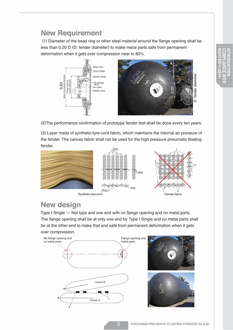
New Requirement (1) Diameter of the bead ring or other steel material around the flange opening shall be
less than 0.20 D (D: fender diameter) to make metal parts safe from permanent
deformation when it gets over compression near to 80%.
New designType I Single — Net type and one end with no flange opening and no metal parts
The flange opening shall be at only one end for Type I Single and no metal parts shall
be at the other end to make that end safe from permanent deformation when it gets
over compression.
(2)The performance confirmation of prototype fender test shall be done every ten years.
(3) Layer made of synthetic-tyre-cord fabric, which maintains the internal air pressure of
the fender. The canvas fabric shall not be used for the high pressure pneumatic floating
fender.
Synthetic-tyre-cord
0.2D
Canvas fabric
Bead ring
Cover plate
Mouth metal
Air chargevalveAir valve
Safety valve
Bea
d rin
g ou
tsid
e di
amet
er
Fla
nge
open
ing
outs
ide
diam
eter
D: fender diameter
0.2D
Warp
Warp
Weft
Weft
1
1 3
2
2
INTR
OD
UC
TION
CO
MPLIA
NC
E WITH
ISO
17357-1:2014

3
3.1 Safety and ReliabilityYokohama Pneumatic Rubber Fenders are constructed of several layers of strong
tire-cord, and are thus resistant to pressure and cutting. The safety factor adopted in the
design of this fender is based on accepted theory and has been proven by extensive
experimentation. Operational experience over a long period of time attests to its high
safety and reliability, and hydraulic pressure tests have proven the strength to be suitable.
Furthermore, large-size fenders are equipped with a safety valve to release the inside air
in the event of accidental over-pressure. The figure below shows data obtained from many
destructive pressure tests at various percentage compressions. Such data are used to
establish a basic minimum endurable pressure (MEP) curve for pneumatic rubber fenders.
3. ADVANTAGES
Fig.3.2 Burst Test at 0% Deflection Fig.3.3 Burst Test at 60% Deflection
Fig.3-1 Burst Test Data to determine Minimum Design Requirements of MEP
800
700
600
500
400
300
200
100
0-10 10 20 30 40 50 60 700
Pre
ssur
e ( k
Pa)
% Deflection
MEP-3300×6500(0%)
MEP3300×6500P50-(60%)
ISO17357-1:2014MEP Requirement@0% Deflection
(350kPa)
ISO17357-1:2014MEP Requirement@60% Deflection
(511kPa)Yokohama's MEPMinimum DesignRequirement(Pneumatic 50)
700×1500L
1200×2000L
2500×4000L
1000×1500L
1350×2500L
2500×5500L
1200×1400L
1500×3000L
3300×6500L
YOKOHAMA PNEUMATIC FLOATING FENDERS 50 & 80
AD
VAN
TAG
ES

4
3.2 No Deterioration or Variation in PerformanceYokohama Pneumatic Rubber Fenders utilize the compressive elasticity of air, therefore
performance deterioration due to fatigue is absent.
In the case of solid rubber fenders or foam-filled fenders, based on data were taken
from comparison tests of Yokohama Fenders, there are variations in performance. Such
performance variations are associated to changes of rubber or foam hardness occurring
as a result of cyclic compression and temperature change.
In the case of Yokohama Pneumatic Rubber Fenders, if the pressure is maintained
properly, such variations are absent.
Yokohama Pneumatic Rubber Fenders also fully comply with the durability test required
by ISO17357-1:2014. After 3000 repetitive cycles, there must be no cracks or other
harmful defects on any part of the fender. Any reduction of the guaranteed energy
absorption (GEA) is not accepted.
The good performance of the Yokohama Pneumatic Rubber Fenders remains unchanged
even at temperatures under -50 degrees Centigrade (-58 degrees Fahrenheit ).
Fig.3-4 Variation in Performance on Cyclic Compression and Temperature
Table 3-1 Cyclic Compression Results for Yokohama Pneumatic Rubber Fenders
120
100
80
60
40
20
0 0
180
160
140
120
100
80
60
40
20
1 10 -50 -40 -30 -20 20 30 40 50 60-10 100100 1000 10000 100000 1000000
Rel
ativ
e R
eact
ion
For
ce(%)
Rel
ativ
e R
eact
ion
For
ce(%)
Number of Compression Cycles Temparature(℃)
Pneumatic
Solid Cell
Foam
Pneumatic
Solid Cell
Items
GEA (index)
Reaction force at GEA (index)
Deflection at GEA (%)
original
1
1
60
After 3000cycles
1
1.04
60.4
YOKOHAMA PNEUMATIC FLOATING FENDERS 50 & 80
AD
VAN
TAG
ES

5
3.3 Advantages at Inclined BerthingShips usually make initial contact with the dock or another ship on STS operations at an
oblique angle. In the case of solid rubber fenders or foam fenders, rated reaction force
and energy absorption decreases considerably at inclined compressions compared with
parallel compression. In order to compensate for the decrease of energy absorption at
inclined compression, it is necessary to use larger sizes in the case of solid rubber
fenders or foam fenders.
In the case of Yokohama Pneumatic Rubber Fenders, energy absorption does not
decrease at inclined compression up to 15 degrees.
Distribution of load is also comparatively even because of the molecular freedom of air
and high flexibility of the multi-layered cord-reinforced rubber membrane. This makes
the body of a pneumatic rubber fender more shape conformant compared to solid or
foam fenders, and thus able to better distribute the load along the hull of a ship or jetty
structure during inclined compression.
Fig.3-5 Reduction of Energy Absorption at Inclined Berthing for Pneumatic, Solid and Foam Fender
Fig.3-6 Load Distribution at Inclined Berthing for Pneumatic, Solid and Foam Fender
120
100
80
60
40
20
0100 20 30 40 50 60
Per
cent
age
of M
ax. E
nerg
y A
bsor
ptio
n
Per
cent
age
of M
ax. R
ated
Ene
rgy
Abs
orpt
ion
Compression(%) Compression(%)
120
100
80
60
40
20
0100 20 30 40 50 60
0~15° 0°5°10°
Per
cent
age
of M
ax. R
ated
Ene
rgy
Abs
orpt
ion
Compression(%)
120
100
80
60
40
20
0100 20 30 40 50 60
0°5°10°
(a) Pneumatic Fender (b) Solid Fender (c) Foam Fender
(a) Pneumatic Fender (b) Solid Fender (c) Foam Fender
YOKOHAMA PNEUMATIC FLOATING FENDERS 50 & 80
AD
VAN
TAG
ES

6
3.4 Most Cost Competitive SystemThe utilization of the compressive elasticity of air, unlike other fenders which need
protector panels, provides completely uniform surface pressure on contact, making
Yokohama Pneumatic Rubber Fenders ideal. The surface pressure of the Yokohama
Pneumatic Rubber Fenders is equal to the internal air pressure. The pressure of some
is below 150kN/m2 (15 ton/m2). Due to low and uniform surface pressure properties,
the Yokohama Pneumatic Rubber Fenders are popular at LNG-ship terminals.
Remarks : The above comparison has been made based on data of Yokohama Pneumatic
fender φ3300×6500L and Yokohama Solid fender RBF2000H
Fig.3-7 Yokohama Pneumatic Fenderφ3300×6500L Fig.3-8 Yokohama Solid Fender RBF2000H
Table 3-2 Cost Competitiveness Comparison based on Uniform Surface Pressure
Pneumatic Fender
70
25
-
5
100
Item
Fender Body
Chain net
Protector Panel
Chain, Anchor
Total
Solid Fender
60
-
75 - 160
15 - 30
150 - 250
Protector Panel
YOKOHAMA PNEUMATIC FLOATING FENDERS 50 & 80
AD
VAN
TAG
ES

7
3.5 Soft Reaction Force for Ship and Jetty StructureAlthough all fenders should be used within their maximum load limit, it often happens that
fenders accidentally receive excess load. The reaction force of Yokohama Pneumatic
Rubber Fenders does not increase sharply, even under excess load conditions.
Therefore, the Yokohama Pneumatic Rubber Fenders perform well in such cases, and
protect ships and mooring facilities. In contrast, the reaction force of solid rubber fenders,
including buckling-type fenders, increases sharply under excess load conditions.
The excess load turns the solid-type fender into a solid rubber block, which cannot
perform as a fender. This often leads to damage of the ship and mooring facilities.
Fig.3-9 above compares the reaction force generated by a typical solid rubber fender to a
pneumatic rubber fender at different compression stages during a typical berthing
operation. The curves are derived from the performance of a solid rubber fender and a
pneumatic rubber fender with the same energy absorption performance. Points A', B', C',
and D' along the reaction curve for the pneumatic fender represent matching energy
absorption performance at point A, B, C, and D on the reaction curve for the solid rubber
fender.
The table below compares the typical reaction loads and hull pressure imposed by solid
and pneumatic type fenders at various compression stages, and it can be seen that the
Yokohama Pneumatic Rubber Fenders are ideal as fender system because of gentle
treatment of ships.
Fig.3-9 Soft Reaction Force for Ship and Jetty Structure
Compression Stage Comparison
Solid fendersYokohama Pneumatic
RubberFenders
Compression stages
A, A'
B, B'
C,C'
D, D'
: First buckling point of solid fender.
: Normal deflection point during typical berthing.
: Designed rated energy point.
: Abnormal berthing
A B C
D
A'B'
C'
D'
Rea
ctio
n fo
rce
Deflection
Pneumatic fender has lower reaction force and exerts lower hull pressure compared to the solid rubber fender
Pneumatic fender has lower reaction force and exerts lower hull pressure compared to the solid rubber fender
Pneumatic fender has slightly higher reaction force only at this point
Pneumatic fender has lower reaction force and exerts lower hull pressure compared to the solid rubber fender
A, A'
B, B'
C, C'
D, D'
: Buckling point of solid fender
: Normal deflection point
: Designed rated energy point
: Abnormal berthing point
YOKOHAMA PNEUMATIC FLOATING FENDERS 50 & 80
AD
VAN
TAG
ES

8
3.6 Lower Mooring Forces under Rough Weather ConditionsDuring mooring under rough weather conditions such as high waves and strong wind,
large ship motions are induced by high waves, long period waves or a resonant effect
between the natural period of a ship and the predominant period of the waves.
This movement results in compression and shearing forces on fenders. The reaction
force and deflection of solid-type fenders under rough weather conditions easily
reaches their respective maximums. Therefore, repeated compression with shearing
force resulting from the movement of ships causes fatigue and often damages
solid-type fenders. On the other hand, the reaction force and deflection of Yokohama
Pneumatic Rubber Fenders do not easily reach the maximum because the reaction
force increases slowly and allowable deflection is wide. Thus, the Yokohama Pneumatic
Rubber Fenders safely protect ships and mooring facilities even under rough weather
conditions.
The use of Pneumatic Rubber Fenders sometimes eliminates the necessity of
constructing a breakwater in the harbor. There are many studies and reports relating to
the above subjects.
Fig.3-10 Model Studies on Ship's Movement with Yokohama Pneumatic Rubber Fender & with Buckling Fender
Fig.3-11 Calculation Results of Harbor Oscillations for Ship Motions moored along Quay Walls
G
Z
X
34m
0 7m 18.3
m
14m
+2
-2
0(m)
+2
-2
0(m)
SWAY
SWAY
1000(sec)
1000(sec)
(a) Pneumatic
(b) Solid (Buckling)
YOKOHAMA PNEUMATIC FLOATING FENDERS 50 & 80
AD
VAN
TAG
ES
9
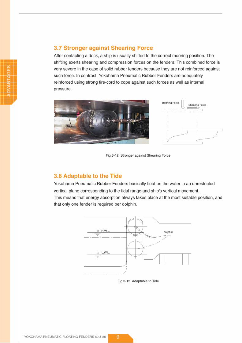
3.7 Stronger against Shearing ForceAfter contacting a dock, a ship is usually shifted to the correct mooring position. The
shifting exerts shearing and compression forces on the fenders. This combined force is
very severe in the case of solid rubber fenders because they are not reinforced against
such force. In contrast, Yokohama Pneumatic Rubber Fenders are adequately
reinforced using strong tire-cord to cope against such forces as well as internal
pressure.
3.8 Adaptable to the TideYokohama Pneumatic Rubber Fenders basically float on the water in an unrestricted
vertical plane corresponding to the tidal range and ship's vertical movement.
This means that energy absorption always takes place at the most suitable position, and
that only one fender is required per dolphin.
Fig.3-12 Stronger against Shearing Force
Fig.3-13 Adaptable to Tide
Berthing ForceShearing Force
dolphinH.W.L.
L.W.L.
YOKOHAMA PNEUMATIC FLOATING FENDERS 50 & 80
AD
VAN
TAG
ES

10
3.9 Simple and Low Cost InstallationThe weight of Yokohama Pneumatic Rubber Fenders
is supported by the water on which it floats.
Therefore, the fender can be moored simply by
means of a guy rope or chain, requiring minimal extra
cost. It can be removed easily to a suitable jetty or
quay when not in use, or transferred to another
mooring point whenever required.
3.10 Low Maintenance CostMaintenance cost is very low. Although the internal pressure will vary with seasonal
changes, the air leakage is so minimal that it is sufficient to check the air pressure only
once a year. The chain net needs to be replaced only once in 3 or 4 years, depending
on ambient conditions.
3.11 Shipping Cost MinimizationIn order to minimize the shipping cost of Yokohama Pneumatic Rubber Fenders, the
fenders are usually packed and shipped in containers or on pallets in vacuumed and
folded down state.
Fig.3-15 Vacuumed and Folded Down Condition forφ4500×9000L-P80
Fig.3-14 φ2500×4000L-P50 Yokohama PneumaticRubber Fenders installed at a dolphin
YOKOHAMA PNEUMATIC FLOATING FENDERS 50 & 80
AD
VAN
TAG
ES
11
4.1 Pressure RatingThere are two initial pressure ratings for Yokohama Pneumatic Rubber Fenders :
1) Pneumatic 50 (P50, Initial internal pressure 50kPa)
2) Pneumatic 80 (P80, Initial internal pressure 80kPa)
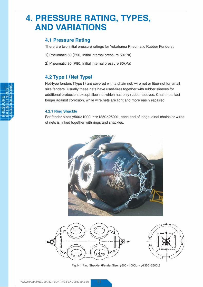
4.2 TypeⅠ(Net Type)Net-type fenders (TypeⅠ) are covered with a chain net, wire net or fiber net for small
size fenders. Usually these nets have used-tires together with rubber sleeves for
additional protection, except fiber net which has only rubber sleeves. Chain nets last
longer against corrosion, while wire nets are light and more easily repaired.
4.2.1 Ring Shackle
For fender sizesφ500×1000L~φ1350×2500L, each end of longitudinal chains or wires
of nets is linked together with rings and shackles.
4. PRESSURE RATING, TYPES, AND VARIATIONS
Fig.4-1 Ring Shackle (Fender Size : φ500×1000L ~ φ1350×2500L)
YOKOHAMA PNEUMATIC FLOATING FENDERS 50 & 80
PR
ES
SU
RE
R
AT
ING
, TY
PE
S
AN
D V
AR
IAT
ION
S

12
4.2.2 Towing Ring
For fender sizes φ1500×3000L~φ3300×6500L, each end of longitudinal chains or
wires of nets is linked together with a towing ring.
4.2.3 Special Towing Ring
For fender sizes φ3300×10600L~φ4500×12000L, each end of longitudinal chains or
wires of nets is linked together with a special towing ring which contains a special
built-in swivel joint.
Fig.4-3 Special Towing Ring (Fender Size: φ3300×10600L ~ φ4500×12000L)
Fig.4-2 Towing Ring (Fender Size: φ1500×3000L ~ φ3300×6500L)
YOKOHAMA PNEUMATIC FLOATING FENDERS 50 & 80
PR
ES
SU
RE
R
AT
ING
, TY
PE
S
AN
D VA
RIA
TIO
NS

13
4.3 TypeⅡ (Sling Type)Sling-type fenders (TypeⅡ)φ500×1000L ~ φ4500×12000L have an attachment eye on
each end for lifting and installation. Handling of sling type fenders is easy due to their
lightweight.
Fig.4-4 Sling Type (Fender Size : φ500×1000L~φ4500×12000L)
YOKOHAMA PNEUMATIC FLOATING FENDERS 50 & 80
PR
ES
SU
RE
R
AT
ING
, TY
PE
S
AN
D V
AR
IAT
ION
S
14
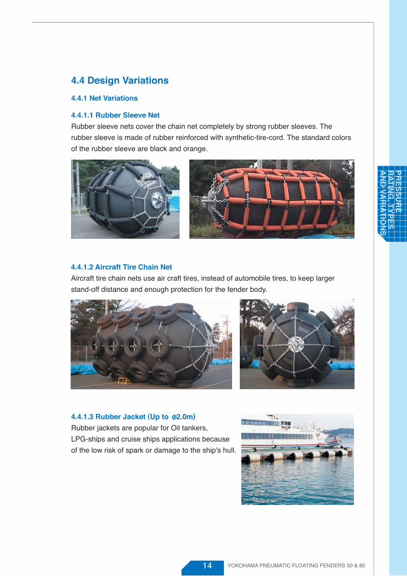
4.4 Design Variations
4.4.1 Net Variations
4.4.1.1 Rubber Sleeve Net
Rubber sleeve nets cover the chain net completely by strong rubber sleeves. The
rubber sleeve is made of rubber reinforced with synthetic-tire-cord. The standard colors
of the rubber sleeve are black and orange.
YOKOHAMA PNEUMATIC FLOATING FENDERS 50 & 80
4.4.1.3 Rubber Jacket (Up to φ2.0m)
Rubber jackets are popular for Oil tankers,
LPG-ships and cruise ships applications because
of the low risk of spark or damage to the ship's hull.
4.4.1.2 Aircraft Tire Chain Net
Aircraft tire chain nets use air craft tires, instead of automobile tires, to keep larger
stand-off distance and enough protection for the fender body.
PR
ES
SU
RE
R
AT
ING
, TY
PE
S
AN
D VA
RIA
TIO
NS
15
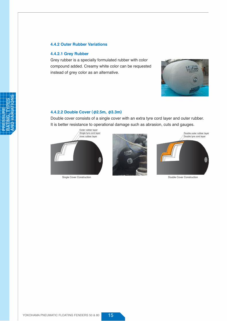
4.4.2 Outer Rubber Variations
4.4.2.1 Grey Rubber
Grey rubber is a specially formulated rubber with color
compound added. Creamy white color can be requested
instead of grey color as an alternative.
YOKOHAMA PNEUMATIC FLOATING FENDERS 50 & 80
Single Cover Construction Double Cover Construction
4.4.2.2 Double Cover (φ2.5m, φ3.3m)
Double cover consists of a single cover with an extra tyre cord layer and outer rubber.
It is better resistance to operational damage such as abrasion, cuts and gauges.
Inner rubber layer
Single tyre cord layerOuter rubber layer
Double tyre cord layerDouble outer rubber layer
PR
ES
SU
RE
R
AT
ING
, TY
PE
S
AN
D V
AR
IAT
ION
S

16 YOKOHAMA PNEUMATIC FLOATING FENDERS 50 & 80
4.4.3 Fender Monitoring System (FMS)
Fender Monitoring System has been developed to monitor offshore Ship-To-Ship (STS)
operation. The system incorporates technology from the design of pneumatic fenders
and the numerical simulation analysis of dynamic ship motion.
The system can simultaneously monitor the state of pneumatic fenders used as shock
absorber between the two ships and the behavior of both ships. This wireless
fender-monitoring system
can be also applied to onshore Ship-to-Dock operation anywhere in the world.
4.4.4 Low-Pressure (LP)
The Low-Pressure fender type is a pneumatic fender designed with a lighter body
construction. It is popular for application requiring large clearance between the ship and
jetty or between two ships but not necessarily needing the high performance of a
standard high-pressure pneumatic fender.
PR
ES
SU
RE
R
AT
ING
, TY
PE
S
AN
D VA
RIA
TIO
NS

17
4.4.5 Light-Weight
Light-Weight fenders are focused on portability,
and are small and light for convenient use with
cruise ships, pleasure boats, and other small
boats.
4.4.6 Vertical
Vertical-Pneumatic Rubber fenders are specially
designed pneumatic fenders that can be
water-ballasted and installed vertically.
They are popular with vessels whose berthing
point is below the water line such as catamaran
ships, semi-submersibles platforms or other
submersibles.
YOKOHAMA PNEUMATIC FLOATING FENDERS 50 & 80
4.4.7 Globuoy
Globuoy is a modified pneumatic fender for use as a surface
or sub-sea buoy in equipment installation, mooring,
anchoring and various offshore operations. It can be used
with higher working pressure or can be filled with pressure
resistant material for various under water applications. The
pneumatic design of the Globuoy makes it easy to handle
and launch due to its light weight. Also, because of the
flexible reinforced rubber body, it is less prone to damaging
or being damaged by the decks or hulls of vessels. It is a
non-collapsible buoy in case of over-submergence.
PR
ES
SU
RE
R
AT
ING
, TY
PE
S
AN
D V
AR
IAT
ION
S

18 YOKOHAMA PNEUMATIC FLOATING FENDERS 50 & 80
PR
ES
SU
RE
R
AT
ING
, TY
PE
S
AN
D VA
RIA
TIO
NS
19
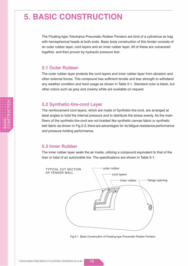
The Floating-type Yokohama Pneumatic Rubber Fenders are kind of a cylindrical air bag
with hemispherical heads at both ends. Basic body construction of this fender consists of
an outer rubber layer, cord layers and an inner rubber layer. All of these are vulcanized
together, and then proven by hydraulic pressure test.
5.1 Outer RubberThe outer rubber layer protects the cord layers and inner rubber layer from abrasion and
other external forces. This compound has sufficient tensile and tear strength to withstand
any weather condition and hard usage as shown in Table 5-1. Standard color is black, but
other colors such as grey and creamy white are available on request.
5.2 Synthetic-tire-cord LayerThe reinforcement cord layers, which are made of Synthetic-tire-cord, are arranged at
ideal angles to hold the internal pressure and to distribute the stress evenly. As the main
fibers of the synthetic-tire-cord are not braided like synthetic canvas fabric or synthetic
belt fabric as shown in Fig.5-2, there are advantages for its fatigue-resistance performance
and pressure-holding performance.
5.3 Inner RubberThe inner rubber layer seals the air inside, utilizing a compound equivalent to that of the
liner or tube of an automobile tire. The specifications are shown in Table 5-1.
5. BASIC CONSTRUCTION
inner rubber
cord layers
outer rubber
flange opening
TYPICAL CUT SECTIONOF FENDER WALL
Fig.5-1 Basic Construction of Floating-type Pneumatic Rubber Fenders
YOKOHAMA PNEUMATIC FLOATING FENDERS 50 & 80
BA
SIC
C
ON
ST
RU
CT
ION

20 YOKOHAMA PNEUMATIC FLOATING FENDERS 50 & 80
BA
SIC
C
ON
ST
RU
CT
ION
1
2
1 : Warp (Tension member)
2 : Weft (no tension member)
Fig.5-2 Basic Construction of Tyre-Cords
Table 5-1 Properties of Outer and Inner Rubber Material
Test Item InspectionMethods
Outer Rubber Inner Rubber
18 Mpa or moreISO 37 : 2011
ISO 37 : 2011
ISO 37 : 2011
ISO 37 : 2011
ISO 34-1 : 2010
ISO 815-1: 2008
Tensile strength
Elongation
Hardness
Tensile strength
Elongation
Hardness
ISO 1431-1 : 2012
ISO 7619-1 : 2010
ISO 7619-1 : 2010
10 Mpa or more
400% or more. 400% or more.BeforeAging
After AgingTest methodISO188:1998
70±1C° × 96 hrs
No requirementTear resistance
Compression test
Static ozone aging test
400 N/cm or more
No requirement
No requirement
60 ±10(Durometer hardness Type A)
50 ±10 (Durometer hardness Type A)
Not less than 80% ofthe original property
Not less than 80% ofthe original property
Not to exceed the originalproperty by more than 8
Not less than 80% ofthe original property
Not less than 80% ofthe original property
Not to exceed the originalproperty by more than 8
30% (70±1C°for 22 hrs)or less
No cracks after elongationby 20% and exposure to
50 pphm at 40C° for 96 hrs

21
5.4 Bead Ring and Flange Opening
5.4.1 Bead Ring
A steel ring is placed at one or both ends of the fender to hold the end of the
reinforcement cord layers. The outside diameter of the bead ring has been designed
smaller than 20% of the fender diameter to maintain
the fender's safe compression up to 80%.
5.4.2 Flange Opening
A steel flange to which air valves are attached is
mounted on the fender to serve as flange
opening. The flange opening is designed
smaller than 12% of the fender diameter to
maintain safe compression up to 80%
compression.
Fig.5-4 Construction of Flange Opening
Fig.5-3 Flange Opening for φ3300
Bead ring
Cover plate
Mouth metal
Air chargevalveAir valve
Safety valve
Bea
d rin
g ou
tsid
e di
amet
er
Fla
nge
open
ing
outs
ide
diam
eter
(Large size) (Medium and small size)
(Large size) (Medium and small size)
Bead ring
Hanging metal
Mouth metal
Air charge valveAir valve
Safety valve
Bea
d rin
g ou
tsid
e di
amet
er
Fla
nge
open
ing
outs
ide
diam
eter
Bead ring
Hanging metalAir valve
Bea
d rin
g ou
tsid
e di
amet
er
Fla
nge
open
ing
outs
ide
diam
eter
Bead ring
Bushing
Air valve Air valve
Bea
d rin
gou
tsid
e di
amet
er
Fla
nge
open
ing
outs
ide
diam
eter
Fla
nge
peni
ngou
tsid
e da
iam
eter
(Type I ) (Type I )
(Type Ⅱ) (Type Ⅱ)
YOKOHAMA PNEUMATIC FLOATING FENDERS 50 & 80
BA
SIC
C
ON
ST
RU
CT
ION

22
5.5 Turn-up SystemThe reinforcement cord layers are turned upward around a bead, which is built-in near
the flange opening, except for small sized fenders. This system was originally invented
for automobile tires and is quite reliable for distributing loads evenly without any
concentration of stress on cord layers.
5.6 Air Valve and Safety ValveMedium and small sized Floating-type Yokohama Pneumatic Rubber Fenders are
equipped with a small air valve, which is the same in size and construction as the air
valve of an automobile tire. This valve serves as both air-check, air charge and release
valve. On the large size fenders, the small air valve, a globe valve and a safety valve are
equipped, the small valve serves for an air-check, the globe valve having a one touch
joint coupler serves for air charge and release, and the safety valve serves for releasing
excess internal pressure when the fender is accidentally over compressed.
Fig.5-5 Air Valve and Safety Valves for Yokohama Floating-type Pneumatic Rubber Fenders
(a) Safety valve for φ2500-φ3300 fenders
(c) Air valve for air charging and air check
(b) Safety valve forφ4500 fenders
YOKOHAMA PNEUMATIC FLOATING FENDERS 50 & 80
BA
SIC
C
ON
ST
RU
CT
ION

23
6.1 Standard SizesThe Yokohama Pneumatic Rubber Fenders are available in the following sizes, which
are generally expressed in terms of diameter by length.
6. SIZES AND PERFORMANCES
Fig.6-1 φ4500×9000L -P80 Yokohama Pneumatic Rubber Fenders
Fig.6-2 Standard Sizes of Yokohama Pneumatic Rubber Fender
1700×3000
500×1000
600×1000
700×1500
1000×1500
1000×2000
1200×2000
1350×2500
1500×3000
2000×3500
2500×40002500×5500
3300×4500
3300×6500
4500×9000
4500×12000
3300×10600
YOKOHAMA PNEUMATIC FLOATING FENDERS 50 & 80
SIZ
ES
AN
D
PE
RFO
RM
AN
CE
S

24
6.2 Performance Table
6.2.1 Pneumatic 50 (Metric)
Table 6-1(a) Pneumatic 50 Standard Sizes
Nominal Size
(kPa) (kNm) (kN) (kPa) (kPa) (kPa) (kg) (kg) (kg) (kg) (kg)
Weight of Net Type (Type Ⅰ)
Approx. Weight of NetInitial
InternalPressure
GuaranteedEnergy
Absorption(GEA)
ReactionForce at GEA
HullPressureat GEA
SafetyValve
Settingpressure
TestingPressure
Weightof
SlingType
(Type Ⅱ)
Approx.FenderBody
Weight ChainNet
WireNet
SyntheticFiber NetEDiameter × Length
(mm × mm)
R p
50
50
50
50
50
50
50
50
50
50
50
50
50
50
50
50
50
6
8
17
32
45
63
102
153
191
308
663
943
1175
1814
3067
4752
6473
22
25
45
73
88
131
200
250
290
405
902
1090
1460
1870
2560
3940
4790
110
120
150
200
220
320
350
530
580
960
1240
1850
1710
2570
4660
5390
6990
30
30
40
80
140
190
200
350
440
640
910
1160
1270
1910
3300
3520
5190
500 × 1000
600 × 1000
700 × 1500
1000 × 1500
1000 × 2000
1200 × 2000
1350 × 2500
1500 × 3000
1700 × 3000
2000 × 3500
2500 × 4000
2500 × 5500
3300 × 4500
3300 × 6500
3300 × 10600
4500 × 9000
4500 × 12000
64
74
137
182
257
297
427
579
639
875
1381
2019
1884
3015
5257
5747
7984
132
126
135
122
132
126
130
132
128
128
137
148
130
146
158
146
154
-
-
-
-
-
-
-
-
-
-
175
175
175
175
175
175
175
200
200
200
200
200
200
200
200
200
200
250
250
250
250
250
250
250
20
22
37
51
57
68
-
-
-
-
-
-
-
-
-
-
-
28
32
51
89
104
147
229
279
320
459
1080
1320
1800
2180
3060
4560
-
Table 6-1(b) Pneumatic 50 Popular Non Standard Sizes
Nominal Size
(kPa) (kNm) (kN) (kPa) (kPa) (kPa) (kg) (kg) (kg) (kg) (kg)
Weight of Net Type (Type Ⅰ)
Approx. Weight of NetInitial
InternalPressure
GuaranteedEnergy
Absorption(GEA)
ReactionForce at GEA
HullPressureat GEA
SafetyValve
Settingpressure
TestingPressure
Weightof
SlingType
(Type Ⅱ)
Approx.FenderBody
Weight ChainNet
WireNet
SyntheticFiber NetEDiameter × Length
(mm × mm)
R p
50
50
50
50
50
50
50
50
50
50
50
400 × 1500
600 × 1200
800 × 1200
1200 × 1800
1350 × 3500
1500 × 2500
2000 × 3000
2000 × 4500
2500 × 7700
3300 × 8600
4500 × 6400
6
10
16
55
152
123
255
418
1350
2443
3238
87
93
116
262
641
464
727
1188
2951
4138
3796
151
132
122
122
141
126
122
137
157
154
133
-
-
-
-
-
-
-
-
175
175
175
200
200
200
200
200
200
200
200
250
250
250
23
28
48
123
255
221
367
480
1370
2220
3400
-
-
240
310
600
440
900
1200
3020
3710
3900
-
-
-
-
-
-
-
-
-
-
-
-
-
-
-
-
-
-
-
-
-
-
33
35
54
139
284
250
421
534
1600
2720
3620
Note : 1. Figures on the table comply with requirements of ISO17357-1:2014. 2. Weight of fender body and net may vary ±10%. 3. Special sizes are available upon request.
YOKOHAMA PNEUMATIC FLOATING FENDERS 50 & 80
SIZE
S A
ND
P
ER
FOR
MA
NC
ES
25
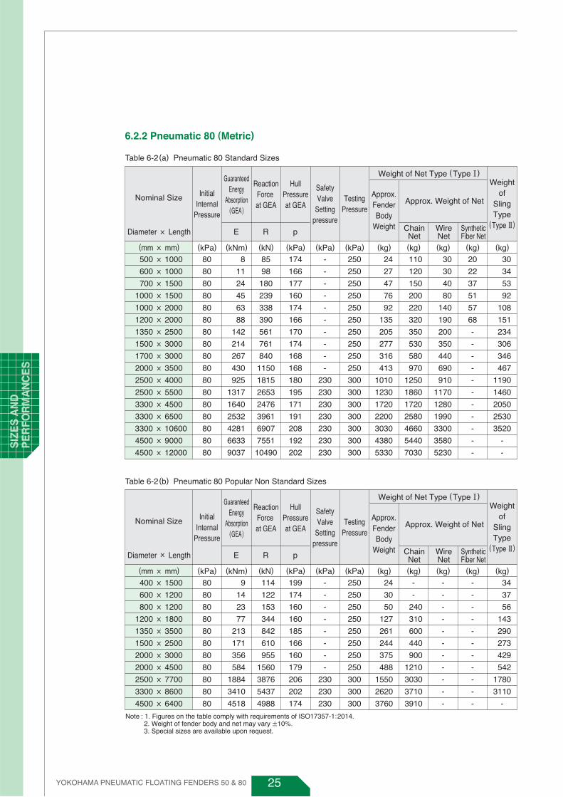
6.2.2 Pneumatic 80 (Metric)
Table 6-2(a) Pneumatic 80 Standard Sizes
Nominal Size
(kPa) (kNm) (kN) (kPa) (kPa) (kPa) (kg) (kg) (kg) (kg) (kg)
Weight of Net Type (Type Ⅰ)
Approx. Weight of NetInitial
InternalPressure
GuaranteedEnergy
Absorption(GEA)
ReactionForce at GEA
HullPressureat GEA
SafetyValve
Settingpressure
TestingPressure
Weightof
SlingType
(Type Ⅱ)
Approx.FenderBody
Weight ChainNet
WireNet
SyntheticFiber NetEDiameter × Length
(mm × mm)
R p
80
80
80
80
80
80
80
80
80
80
80
80
80
80
80
80
80
8
11
24
45
63
88
142
214
267
430
925
1317
1640
2532
4281
6633
9037
24
27
47
76
92
135
205
277
316
413
1010
1230
1720
2200
3030
4380
5330
110
120
150
200
220
320
350
530
580
970
1250
1860
1720
2580
4660
5440
7030
30
30
40
80
140
190
200
350
440
690
910
1170
1280
1990
3300
3580
5230
500 × 1000
600 × 1000
700 × 1500
1000 × 1500
1000 × 2000
1200 × 2000
1350 × 2500
1500 × 3000
1700 × 3000
2000 × 3500
2500 × 4000
2500 × 5500
3300 × 4500
3300 × 6500
3300 × 10600
4500 × 9000
4500 × 12000
85
98
180
239
338
390
561
761
840
1150
1815
2653
2476
3961
6907
7551
10490
174
166
177
160
174
166
170
174
168
168
180
195
171
191
208
192
202
-
-
-
-
-
-
-
-
-
-
230
230
230
230
230
230
230
250
250
250
250
250
250
250
250
250
250
300
300
300
300
300
300
300
20
22
37
51
57
68
-
-
-
-
-
-
-
-
-
-
-
30
34
53
92
108
151
234
306
346
467
1190
1460
2050
2530
3520
-
-
Table 6-2(b) Pneumatic 80 Popular Non Standard Sizes
Nominal Size
(kPa) (kNm) (kN) (kPa) (kPa) (kPa) (kg) (kg) (kg) (kg) (kg)
Weight of Net Type (Type Ⅰ)
Approx. Weight of NetInitial
InternalPressure
GuaranteedEnergy
Absorption(GEA)
ReactionForce at GEA
HullPressureat GEA
SafetyValve
Settingpressure
TestingPressure
Weightof
SlingType
(Type Ⅱ)
Approx.FenderBody
Weight ChainNet
WireNet
SyntheticFiber NetEDiameter × Length
(mm × mm)
R p
80
80
80
80
80
80
80
80
80
80
80
400 × 1500
600 × 1200
800 × 1200
1200 × 1800
1350 × 3500
1500 × 2500
2000 × 3000
2000 × 4500
2500 × 7700
3300 × 8600
4500 × 6400
9
14
23
77
213
171
356
584
1884
3410
4518
114
122
153
344
842
610
955
1560
3876
5437
4988
199
174
160
160
185
166
160
179
206
202
174
-
-
-
-
-
-
-
-
230
230
230
250
250
250
250
250
250
250
250
300
300
300
24
30
50
127
261
244
375
488
1550
2620
3760
-
-
240
310
600
440
900
1210
3030
3710
3910
-
-
-
-
-
-
-
-
-
-
-
-
-
-
-
-
-
-
-
-
-
-
34
37
56
143
290
273
429
542
1780
3110
-
Note : 1. Figures on the table comply with requirements of ISO17357-1:2014. 2. Weight of fender body and net may vary ±10%. 3. Special sizes are available upon request.
YOKOHAMA PNEUMATIC FLOATING FENDERS 50 & 80
SIZ
ES
AN
D
PE
RFO
RM
AN
CE
S

26
6.2.3 Pneumatic 50 (U.S. Customary)
Table 6-3(a) Pneumatic 50 Standard Sizes
Nominal Size
(kips) (kips) (kips) (kips/ft 2) (psi) (psi) (lbs) (lbs) (lbs) (lbs) (lbs)
Weight of Net Type (Type Ⅰ)
Approx. Weight of NetInitial
InternalPressure
GuaranteedEnergy
Absorption(GEA)
ReactionForce at GEA
HullPressureat GEA
SafetyValve
Settingpressure
TestingPressure
Weightof
SlingType
(Type Ⅱ)
Approx.FenderBody
Weight ChainNet
WireNet
SyntheticFiber NetEDiameter × Length
(mm × mm)(f t × f t )
R p
7.3
7.3
7.3
7.3
7.3
7.3
7.3
7.3
7.3
7.3
7.3
7.3
7.3
7.3
7.3
7.3
7.3
4.4
5.9
12.5
23.6
33.2
46.5
75.3
113
141
227
489
696
867
1339
2264
3507
4777
49
55
99
161
194
289
441
551
639
893
1989
2403
3219
4123
5645
8688
10562
243
265
331
441
485
706
772
1169
1279
2117
2734
4079
3771
5667
10275
11885
15413
66
66
88
176
309
419
441
772
970
1411
2007
2558
2800
4212
7277
7762
11444
500 × 1000
600 × 1000
700 × 1500
1000 × 1500
1000 × 2000
1200 × 2000
1350 × 2500
1500 × 3000
1700 × 3000
2000 × 3500
2500 × 4000
2500 × 5500
3300 × 4500
3300 × 6500
3300 × 10600
4500 × 9000
4500 × 12000
1.6 × 3
2 × 3
2.3 × 5
3 × 5
3 × 6.5
4 × 6.5
4.4 × 8
5 × 10
5.6 × 10
6.5×11.5
8 × 13
8 × 18
11 × 15
11 × 21
11 × 35
15 × 30
15 × 40
14.4
16.7
30.8
41.0
57.8
66.8
96.1
130
144
197
311
454
424
678
1183
1293
1796
2.72
2.59
2.78
2.51
2.72
2.59
2.67
2.72
2.63
2.63
2.82
3.04
2.67
3.00
3.25
3.00
3.17
-
-
-
-
-
-
-
-
-
-
25.4
25.4
25.4
25.4
25.4
25.4
25.4
29.0
29.0
29.0
29.0
29.0
29.0
29.0
29.0
29.0
29.0
36.3
36.3
36.3
36.3
36.3
36.3
36.3
44
49
82
112
126
150
-
-
-
-
-
-
-
-
-
-
-
62
71
112
196
229
324
505
615
705
1012
2381
2911
3969
4807
6747
-
10054
Table 6-3(b) Pneumatic 50 Popular Non Standard Sizes
Nominal Size
(kips) (kips) (kips) (kips/ft 2) (psi) (psi) (lbs) (lbs) (lbs) (lbs) (lbs)
Weight of Net Type (Type Ⅰ)
Approx. Weight of NetInitial
InternalPressure
GuaranteedEnergy
Absorption(GEA)
ReactionForce at GEA
HullPressureat GEA
SafetyValve
Settingpressure
TestingPressure
Weightof
SlingType
(Type Ⅱ)
Approx.FenderBody
Weight ChainNet
WireNet
SyntheticFiber NetEDiameter × Length
(mm × mm)(f t × f t )
R p
7.3
7.3
7.3
7.3
7.3
7.3
7.3
7.3
7.3
7.3
7.3
4.4
7.4
11.8
40.6
112
90.8
188
309
996
1803
2390
51
62
10
271
562
487
809
1058
3021
4895
7497
-
-
529
684
1323
970
1985
2646
6659
8181
8600
-
-
-
-
-
-
-
-
-
-
-
-
-
-
-
-
-
-
-
-
-
-
400 × 1500
600 × 1200
800 × 1200
1200 × 1800
1350 × 3500
1500 × 2500
2000 × 3000
2000 × 4500
2500 × 7700
3300 × 8600
4500 × 6400
1.3 × 5
2 × 4
2.6 × 4
4 × 6
4.4×11.5
5 × 8
6.5 × 10
6.5 × 15
8 × 25
11 × 28
15 × 21
19.6
20.9
26.1
59.0
144
104
164
267
664
931
854
3.11
2.72
2.51
2.51
2.90
2.59
2.51
2.82
3.23
3.17
2.74
-
-
-
-
-
-
-
-
25.4
25.4
25.4
29.0
29.0
29.0
29.0
29.0
29.0
29.0
29.0
36.3
36.3
36.3
73
77
119
306
626
551
928
1177
3528
5998
7981
Note : 1. Figures on the table comply with requirements of ISO17357-1:2014. 2. Weight of fender body and net may vary ±10%. 3. Special sizes are available upon request.
YOKOHAMA PNEUMATIC FLOATING FENDERS 50 & 80
SIZE
S A
ND
P
ER
FOR
MA
NC
ES
27
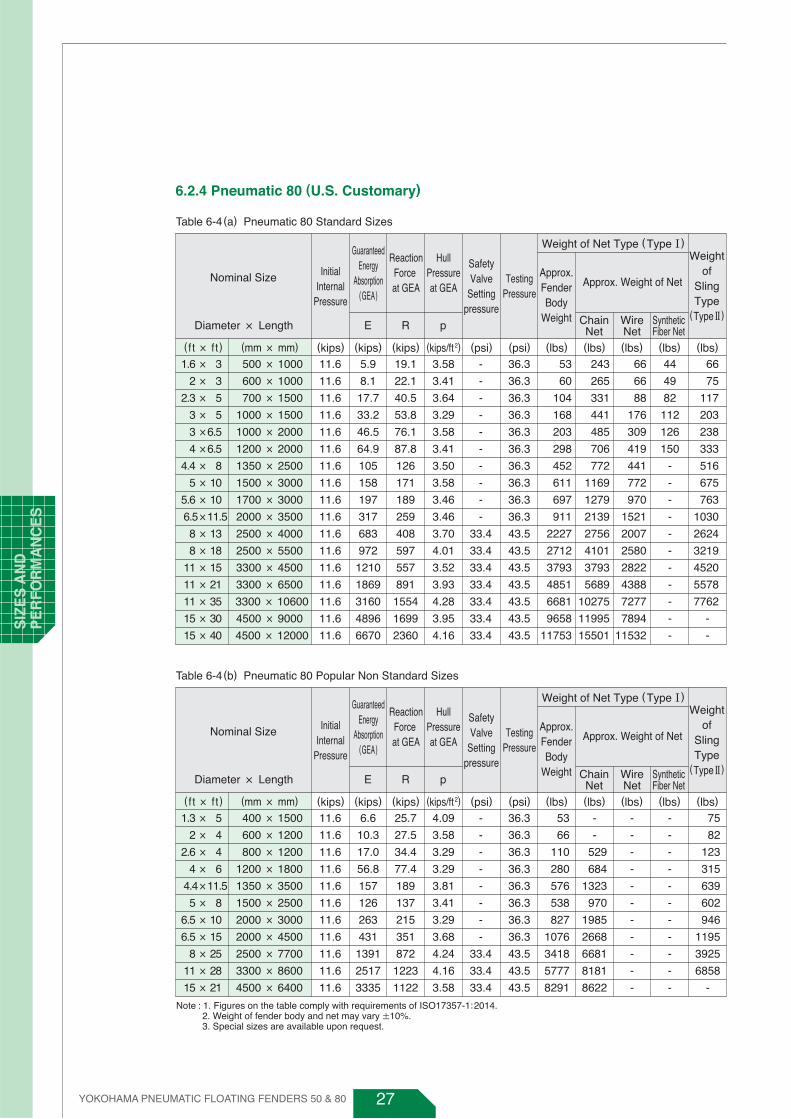
6.2.4 Pneumatic 80 (U.S. Customary)
Table 6-4(a) Pneumatic 80 Standard Sizes
Nominal Size
(kips) (kips) (kips) (kips/ft 2) (psi) (psi) (lbs) (lbs) (lbs) (lbs) (lbs)
Weight of Net Type (Type Ⅰ)
Approx. Weight of NetInitial
InternalPressure
GuaranteedEnergy
Absorption(GEA)
ReactionForce at GEA
HullPressureat GEA
SafetyValve
Settingpressure
TestingPressure
Weightof
SlingType
(Type Ⅱ)
Approx.FenderBody
Weight ChainNet
WireNet
SyntheticFiber NetEDiameter × Length
(mm × mm)(f t × f t )
R p
11.6
11.6
11.6
11.6
11.6
11.6
11.6
11.6
11.6
11.6
11.6
11.6
11.6
11.6
11.6
11.6
11.6
5.9
8.1
17.7
33.2
46.5
64.9
105
158
197
317
683
972
1210
1869
3160
4896
6670
53
60
104
168
203
298
452
611
697
911
2227
2712
3793
4851
6681
9658
11753
243
265
331
441
485
706
772
1169
1279
2139
2756
4101
3793
5689
10275
11995
15501
66
66
88
176
309
419
441
772
970
1521
2007
2580
2822
4388
7277
7894
11532
500 × 1000
600 × 1000
700 × 1500
1000 × 1500
1000 × 2000
1200 × 2000
1350 × 2500
1500 × 3000
1700 × 3000
2000 × 3500
2500 × 4000
2500 × 5500
3300 × 4500
3300 × 6500
3300 × 10600
4500 × 9000
4500 × 12000
1.6 × 3
2 × 3
2.3 × 5
3 × 5
3 ×6.5
4 ×6.5
4.4 × 8
5 × 10
5.6 × 10
6.5×11.5
8 × 13
8 × 18
11 × 15
11 × 21
11 × 35
15 × 30
15 × 40
19.1
22.1
40.5
53.8
76.1
87.8
126
171
189
259
408
597
557
891
1554
1699
2360
3.58
3.41
3.64
3.29
3.58
3.41
3.50
3.58
3.46
3.46
3.70
4.01
3.52
3.93
4.28
3.95
4.16
-
-
-
-
-
-
-
-
-
-
33.4
33.4
33.4
33.4
33.4
33.4
33.4
36.3
36.3
36.3
36.3
36.3
36.3
36.3
36.3
36.3
36.3
43.5
43.5
43.5
43.5
43.5
43.5
43.5
44
49
82
112
126
150
-
-
-
-
-
-
-
-
-
-
-
66
75
117
203
238
333
516
675
763
1030
2624
3219
4520
5578
7762
-
-
Table 6-4(b) Pneumatic 80 Popular Non Standard Sizes
Nominal Size
(kips) (kips) (kips) (kips/ft 2) (psi) (psi) (lbs) (lbs) (lbs) (lbs) (lbs)
Weight of Net Type (Type Ⅰ)
Approx. Weight of NetInitial
InternalPressure
GuaranteedEnergy
Absorption(GEA)
ReactionForce at GEA
HullPressureat GEA
SafetyValve
Settingpressure
TestingPressure
Weightof
SlingType
(Type Ⅱ)
Approx.FenderBody
Weight ChainNet
WireNet
SyntheticFiber NetEDiameter × Length
(mm × mm)(f t × f t )
R p
11.6
11.6
11.6
11.6
11.6
11.6
11.6
11.6
11.6
11.6
11.6
6.6
10.3
17.0
56.8
157
126
263
431
1391
2517
3335
53
66
110
280
576
538
827
1076
3418
5777
8291
-
-
529
684
1323
970
1985
2668
6681
8181
8622
-
-
-
-
-
-
-
-
-
-
-
-
-
-
-
-
-
-
-
-
-
-
400 × 1500
600 × 1200
800 × 1200
1200 × 1800
1350 × 3500
1500 × 2500
2000 × 3000
2000 × 4500
2500 × 7700
3300 × 8600
4500 × 6400
1.3 × 5
2 × 4
2.6 × 4
4 × 6
4.4×11.5
5 × 8
6.5 × 10
6.5 × 15
8 × 25
11 × 28
15 × 21
25.7
27.5
34.4
77.4
189
137
215
351
872
1223
1122
4.09
3.58
3.29
3.29
3.81
3.41
3.29
3.68
4.24
4.16
3.58
-
-
-
-
-
-
-
-
33.4
33.4
33.4
36.3
36.3
36.3
36.3
36.3
36.3
36.3
36.3
43.5
43.5
43.5
75
82
123
315
639
602
946
1195
3925
6858
-
Note : 1. Figures on the table comply with requirements of ISO17357-1:2014. 2. Weight of fender body and net may vary ±10%. 3. Special sizes are available upon request.
YOKOHAMA PNEUMATIC FLOATING FENDERS 50 & 80
SIZ
ES
AN
D
PE
RFO
RM
AN
CE
S

28
(U.S.Customary)
6.2.5 Light-Weight
(U.S.Customary)
(U.S.Customary)
6.2.6 Low-Pressure
6.2.7 Vertical-Pneumatic
YOKOHAMA PNEUMATIC FLOATING FENDERS 50 & 80
SIZE
S A
ND
P
ER
FOR
MA
NC
ES
Nominal size
GuaranteedEnergy
AbsorptionGEA
InitialInternal
Pressure
ReactionForce at
GEA
HullPressureat GEA
Weight ofSling Type(Type Ⅱ)
Testing Pressure
80
80
500 × 1000
1000 × 1500
8
45
85
239
174
160
250
250
24
65
EDiameter × Length
(mm × mm) (kNm)(kPa) (kN) (kPa) (kPa) (kg)
R p
Nominal size
GuaranteedEnergy
AbsorptionGEA
InitialInternal
Pressure
ReactionForce at
GEA
HullPressureat GEA
Weight ofSling Type(Type Ⅱ)
Testing Pressure
11.6
11.6
500 × 1000
1000 × 1500
1.6 × 33 × 5
5.9
33.2
19.1
53.8
3.58
3.29
36.3
36.3
53
143
EDiameter × Length
(mm × mm)(ft × ft) (ft-kips)(psi) (kips) (kips/ft2) (psi) (lbs)
R p
Nominal size
GuaranteedEnergy
AbsorptionGEA
InitialInternal
Pressure
ReactionForce at
GEA
HullPressureat GEA
Weight ofSling Type(Type Ⅱ)
Testing Pressure
10
10
2500 × 9100
3300 × 12700
676
1565
1901
3439
88
89
40
40
1190
1930
EDiameter × Length
(mm × mm) (kNm)(kPa) (kN) (kPa) (kPa) (kg)
R p
Nominal size Weight ofBody
InitialInternal
Pressure
50
50
50
50
50
50
50
2000 × 6000
2500 × 9100
3300 × 6500
3300 × 8600
3300 × 10600
4500 × 9000
4500 × 12000
1000
2200
3000
3600
4100
5810
7680
Diameter × Length
(mm × mm) (kg)(kPa)
Nominal size Weight ofBody
InitialInternal
Pressure
7.3
7.3
7.3
7.3
7.3
7.3
7.3
6.5 × 20
8 × 30
11 × 21
11 × 28
11 × 35
15 × 30
15 × 40
2000 × 6000
2500 × 9100
3300 × 6500
3300 × 8600
3300 × 10600
4500 × 9000
4500 × 12000
2205
4851
6615
7938
9041
12811
16934
Diameter × Length
(mm × mm)(ft × ft) (lbs)(psi)
Nominal size
GuaranteedEnergy
AbsorptionGEA
InitialInternal
Pressure
ReactionForce at
GEA
HullPressureat GEA
SafetyValve
SettingPressure
Weight ofSling Type(Type Ⅱ)
Testing Pressure
1.5
1.5
2500 × 91008 × 30
11 × 42
499
1155
427.7
773.8
1.81
1.83
5.8
5.8
2624
4366
EDiameter × Length
(mm × mm)(ft × ft) (ft-kips)(psi) (kips) (kips/ft2) (psi)
-
-
(psi) (lbs)
R p
3300 × 12700

29
6.3 Safety Design and Pressure Requirements
6.3.1 Over-compression
The guaranteed energy absorption of Yokohama Pneumatic Rubber Fenders is the energy
absorption at 60% deflection. This figure should be observed in engineering design and in
actual operation. However, even if the fender is accidentally over-deflected beyond this
guaranteed value, the Yokohama Pneumatic Rubber Fender has a wide safety margin as
shown in Fig.6-4 and Table 6-5 below. These curves and table express the capacity for
energy absorption and reaction force until the time of ultimate deflection when the
deflection of fender reach the largest diameter of mouthpiece metal parts. This is shown
by using the guaranteed energy absorption and reaction force as the index value of 1.
The figures and table show the wide safety margin of our pneumatic fenders in absorbing
energy and low reaction force.
With Safety Valve (SV) :
Energy Absorption (Index)
Reaction Force (Index)
Internal Pressure (kPa)
DEF (%)
Without Safety Valve (SV) :
Energy Absorption (Index)
Reaction Force (Index)
Internal Pressure (kPa)
DEF (%)
1.0
1.0
146
60 (%)
1.3
1.2
175
65 (%)
1.6
1.2
175
70 (%)
2.0
1.2
175
75 (%)
2.3
1.2
175
80 (%)
1.0
1.0
146
60 (%)
1.3
1.2
175
65 (%)
1.7
1.5
215
70 (%)
2.1
2.0
274
75 (%)
2.7
2.6
367
80 (%)
Table 6-5 Safety Design at Over-compression
At GuaranteedEnergy
Absorption
At Safety ValveOperating Point
(Approx)- -
At DeflectionIimited by Mouthpiece
Metal (Approx.)
Fig.6-4 Safety Design at Over-compression
Note : 1. Table shows study results based on a φ3300 × 6500L pneumatic 50 fender. 2. They are studied based on the condition that air release capacity of the safety valve is not exceeded.
4.0
3.5
3.0
2.5
2.0
1.5
1.0
0.5
0.0
1200
1050
900
750
600
450
300
150
00 10 20 30 40
Safety valve working point
EN
ER
GY
AB
SO
RP
TIO
N I
ND
EX
INN
ER
PR
ES
SU
RE
( kP
a)
Guaranteed energy absorption
50 60 70 80 90
2.7 times
2.3 times
4.0
3.5
3.0
2.5
2.0
1.5
1.0
0.5
0.0
1200
1050
900
750
600
450
300
150
00 10 20 30 40
DEFLECTION (%)DEFLECTION (%)
Safety valve working point
RE
AC
TIO
N F
OR
CE
IN
DE
X
INN
ER
PR
ES
SU
RE
( kP
a)
Rated Reaction Force
50 60 70 80 90
1.2 times
2.6 times
R / R60 without SVR' / R60 with SVP (kPa) without SVP'(kPa) with SV
E / E60 without SVE'/ E60 with SVP (kPa) without SVP'(kPa) with SV
175kPa 175kPa
YOKOHAMA PNEUMATIC FLOATING FENDERS 50 & 80
SIZ
ES
AN
D
PE
RFO
RM
AN
CE
S

30
6.3.2 Endurable Pressure at 0% and 60% Deflection
Minimum endurable pressure, the safety valve pressure and the test pressure for each
size of Pneumatic 50 and Pneumatic 80 are shown below.
Table 6-6 Pressure Requirements (Pneumatic 50)
Internal pressureNominal size
Minimum endurable pressure Safety-valve pressure
setting(kPa)
Test pressureat 0%
deflection(kPa)
at 0%deflection
(kPa)
at 60%deflection
(kPa)
at 0%deflection
(kPa)
at 60%deflection
(kPa)
Diameter × Length
(mm × mm)
50
50
50
50
50
50
50
50
50
50
50
50
50
50
50
50
50
500 × 1000
600 × 1000
700 × 1500
1000 × 1500
1000 × 2000
1200 × 2000
1350 × 2500
1500 × 3000
1700 × 3000
2000 × 3500
2500 × 4000
2500 × 5500
3300 × 4500
3300 × 6500
3300 × 10600
4500 × 9000
4500 × 12000
132
126
135
122
132
126
130
132
128
128
137
148
130
146
158
146
154
300
300
300
300
300
300
300
300
300
300
350
350
350
350
350
350
350
462
441
473
427
462
441
455
462
448
448
480
518
455
511
553
511
539
-
-
-
-
-
-
-
-
-
-
175
175
175
175
175
175
175
200
200
200
200
200
200
200
200
200
200
250
250
250
250
250
250
250
Table 6-7 Pressure Requirements (Pneumatic 80)
Internal pressureNominal size
Minimum endurable pressure Safety-valve pressure
setting(kPa)
Test pressureat 0%
deflection(kPa)
at 0%deflection
(kPa)
at 60%deflection
(kPa)
at 0%deflection
(kPa)
at 60%deflection
(kPa)
Diameter × Length
(mm × mm)
80
80
80
80
80
80
80
80
80
80
80
80
80
80
80
80
80
500 × 1000
600 × 1000
700 × 1500
1000 × 1500
1000 × 2000
1200 × 2000
1350 × 2500
1500 × 3000
1700 × 3000
2000 × 3500
2500 × 4000
2500 × 5500
3300 × 4500
3300 × 6500
3300 × 10600
4500 × 9000
4500 × 12000
174
166
177
160
174
166
170
174
168
168
180
195
171
191
208
192
202
480
480
480
480
480
480
480
480
480
480
560
560
560
560
560
560
560
609
581
620
560
609
581
595
609
588
588
630
683
599
669
728
672
707
-
-
-
-
-
-
-
-
-
-
230
230
230
230
230
230
230
250
250
250
250
250
250
250
250
250
250
300
300
300
300
300
300
300
YOKOHAMA PNEUMATIC FLOATING FENDERS 50 & 80
SIZE
S A
ND
P
ER
FOR
MA
NC
ES
31
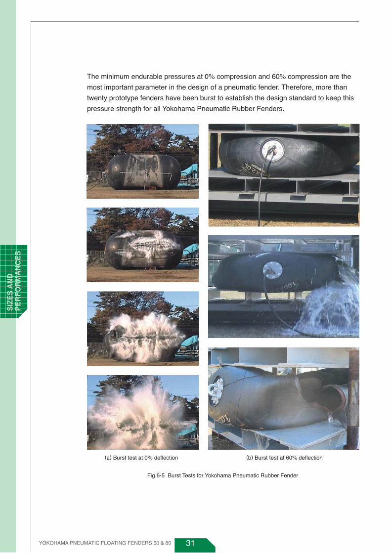
The minimum endurable pressures at 0% compression and 60% compression are the
most important parameter in the design of a pneumatic fender. Therefore, more than
twenty prototype fenders have been burst to establish the design standard to keep this
pressure strength for all Yokohama Pneumatic Rubber Fenders.
(a) Burst test at 0% deflection (b) Burst test at 60% deflection
Fig.6-5 Burst Tests for Yokohama Pneumatic Rubber Fender
YOKOHAMA PNEUMATIC FLOATING FENDERS 50 & 80
SIZ
ES
AN
D
PE
RFO
RM
AN
CE
S

32
Fig.6-6 Compression Speed Effect on Performance for Yokohama Pneumatic Rubber Fenders
1.5
1.4
1.3
1.2
1.1
1.0
0.9
0.8
R /Rs
0.1 1 10 100
Compression rate (% / s)
(a) Reaction force
1.5
1.4
1.3
1.2
1.1
1.0
0.9
0.8
E /Es
0.1 1 10
Compression rate (% / s)
(b) Energy absorption
6.4 Fender Compression SpeedPerformance requirements of reaction force and energy absorption for Yokohama
Pneumatic Rubber Fenders are basically evaluated for static conditions with a constant
slow compression speed of 0.001m/s. However, during actual ship berthing operations,
the Yokohama Pneumatic Rubber Fenders are dynamically compressed at speeds over
0.05m/s. The Fig.6-6 below shows the effect of compression speed at 60% deflection
against the static rated values on reaction force and energy absorption. The reaction force
and energy absorption increase together with compression rate. In actual ship berthing
conditions those values are about 20% higher compared to those of static compression.
6.5 Temperature EffectThe performance of Yokohama Pneumatic Rubber Fenders is engineered based on air
pressure. Therefore, the performance of the fenders is stable relative to temperature
variations when the initial internal pressure is set to be the specified pressure.
YOKOHAMA PNEUMATIC FLOATING FENDERS 50 & 80
SIZE
S A
ND
P
ER
FOR
MA
NC
ES
33
7. FENDER SELECTION
7.1 Ship-to-ShipThe fender selection procedure for ship-to-ship operations is outlined below.
Two ship types, sizes and weather conditions such as Calm, Moderate and Rough are
initially confirmed.
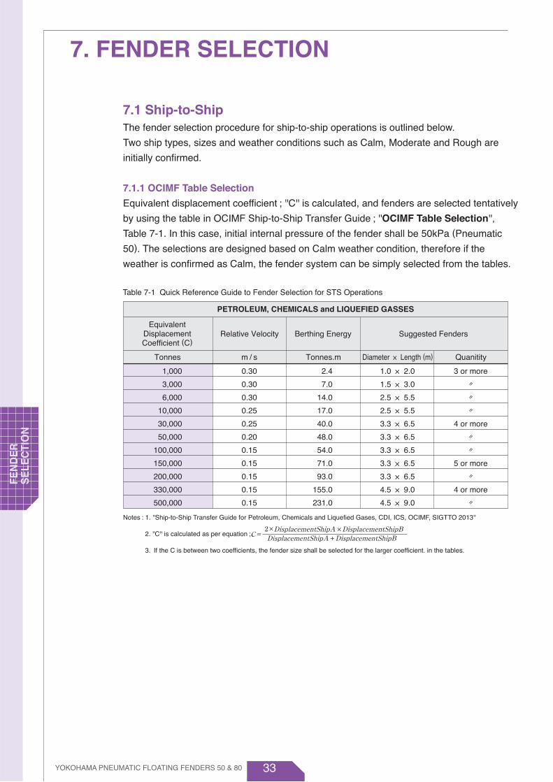
7.1.1 OCIMF Table Selection
Equivalent displacement coefficient ; ''C'' is calculated, and fenders are selected tentatively
by using the table in OCIMF Ship-to-Ship Transfer Guide ; ''OCIMF Table Selection'',
Table 7-1. In this case, initial internal pressure of the fender shall be 50kPa (Pneumatic
50). The selections are designed based on Calm weather condition, therefore if the
weather is confirmed as Calm, the fender system can be simply selected from the tables.
1,000
3,000
6,000
10,000
30,000
50,000
100,000
150,000
200,000
330,000
500,000
0.30
0.30
0.30
0.25
0.25
0.20
0.15
0.15
0.15
0.15
0.15
2.4
7.0
14.0
17.0
40.0
48.0
54.0
71.0
93.0
155.0
231.0
1.0 × 2.0
1.5 × 3.0
2.5 × 5.5
2.5 × 5.5
3.3 × 6.5
3.3 × 6.5
3.3 × 6.5
3.3 × 6.5
3.3 × 6.5
4.5 × 9.0
4.5 × 9.0
3 or more
〃〃〃
4 or more
〃〃
5 or more
〃4 or more
〃
EquivalentDisplacementCoefficient (C)
Relative Velocity
Tonnes m / s Tonnes.m Diameter × Length (m) Quanitity
Berthing Energy
PETROLEUM, CHEMICALS and LIQUEFIED GASSES
Suggested Fenders
Notes : 1. ''Ship-to-Ship Transfer Guide for Petroleum, Chemicals and Liquefied Gases, CDI, ICS, OCIMF, SIGTTO 2013''
2. ''C'' is calculated as per equation ;
3. If the C is between two coefficients, the fender size shall be selected for the larger coefficient. in the tables.
C=DisplacementShipA DisplacementShipB
DisplacementShipA DisplacementShipB2× ×
+
YOKOHAMA PNEUMATIC FLOATING FENDERS 50 & 80
FEN
DE
R
SE
LEC
TIO
N
Table 7-1 Quick Reference Guide to Fender Selection for STS Operations

34
7.1.2 Berthing Energy Selection
Berthing energy of the two ships is then calculated ; "Berthing Energy Selection".
If energy absorption capacity of the tentative selected fender (Ef) is larger than the
calculated berthing energy (E), it is confirmed that a suitable fender selection has been
made. If the fender energy absorption capacity is less than the calculated berthing
energy, the tentatively selected fender shall be upgraded.
7.1.3 Fender Selection procedure
Fender selection procedure for ship-to-ship operations is illustrated below.
7.1.4 Equivalent Displacement Coefficient
The equivalent displacement coefficient will vary depending on each ship particulars
and the type of Ship-to-Ship operation. The three types of Ship-to-Ship operations are
described in Table 7-2 below.
( i )
( i i )
(iii)
Full-Full berthing
Ordinary lightering
Reverse lightering
Discharging ship; (Full)
Discharging ship; (Full)
Receiving ship; (Ballast)
Ship-A Larger Ship Ship-B Smaller Ship
Receiving ship (Full)
Receiving ship (Ballast)
Discharging ship (Full)
Fig.7-1 Fender Selection for Ship-to-Ship Usage
・WA・WBWA WB
OCIMF Table Selection Berthing Energy Selection
Equivalent Displacement Coefficient ;
Max. Fender Energy Ef > Berthing Energy; E
Suitable Fender Selected
Berthing Energy ;
Fender Selection by C based on Table 7-1 or Table 7-2(Max. Fender Energy Absorption; Ef )
WA : Displacement of Ship-AWB : Displacement of Ship-B
Ship Types, Ship Sizes and ConditionsRelative Approaching Velocity (V) determined fromWeather Conditions (Calm, Moderate, and Rough)
C=
WVA・WVBWVA WVB
WVAB=
WVA=WA・CmA, WVB=WB・CmB
2+
+
WVAB・V 2E = Ce SF21
× ×
Fender to be upgraded
No
Yes
YOKOHAMA PNEUMATIC FLOATING FENDERS 50 & 80
FEN
DE
RS
ELE
CTIO
N
Table 7-2 Quick Reference Guide to Fender Selection for STS Operations

35
It is obvious from Fig.7-2 below that ship’s displacement at the ordinary lightering or the
reverse lightering operation is smaller compared to that for the full-full berthing,
however, at the severest condition when the two vessels are both almost full, the
displacement become similar to condition of the full-full berthing and therefore the
fender system should be selected considering the full-full berthing even in case of the
ordinary lightering and the reverse lightering operation.
( i ) Full Covered Berthing
( ii ) Ordinary lightering
Ship-A
Full-Loaded Full-Loaded
Ship-B
Ship-A
Discharging Ship Receiving Ship
Full-Loaded Ballast
Ship-B
VLCC oil
Ship-A
Discharging Ship Receiving Ship
Almost Full-Loaded
The severest condition
Almost Full-Loaded
Ship-B
VLCC oil
( iii ) Reverse lightering
Ship-A
Receiving Ship Discharging Ship
Ballast Full-Loaded
Ship-B
VLCCoil
Ship-A
Receiving Ship Discharging Ship
Almost Full-LoadedThe severest condition
Almost Full-Loaded
Ship-B
VLCCoil
Fig.7-2 Equivalent Displacement Coefficient in Ship-to-Ship Operations
YOKOHAMA PNEUMATIC FLOATING FENDERS 50 & 80
FEN
DE
R
SE
LEC
TIO
N
36
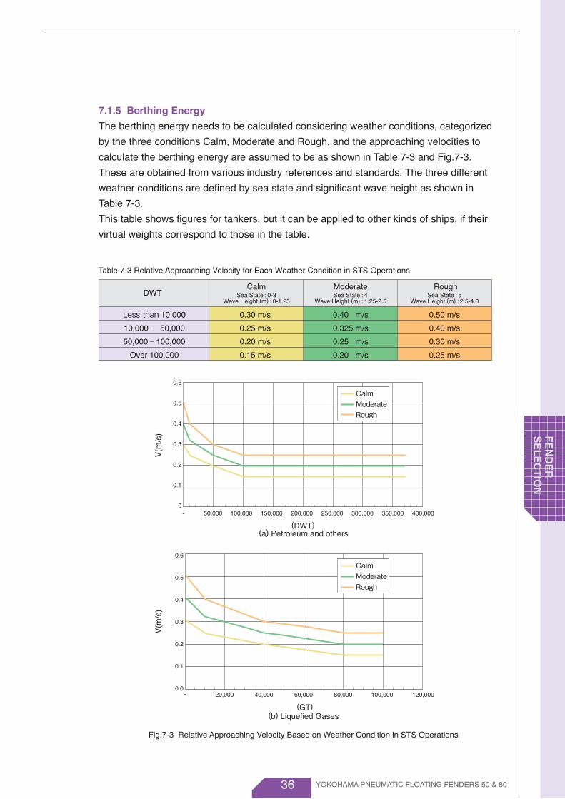
7.1.5 Berthing Energy
The berthing energy needs to be calculated considering weather conditions, categorized
by the three conditions Calm, Moderate and Rough, and the approaching velocities to
calculate the berthing energy are assumed to be as shown in Table 7-3 and Fig.7-3.
These are obtained from various industry references and standards. The three different
weather conditions are defined by sea state and significant wave height as shown in
Table 7-3.
This table shows figures for tankers, but it can be applied to other kinds of ships, if their
virtual weights correspond to those in the table.
Table 7-3 Relative Approaching Velocity for Each Weather Condition in STS Operations
Less than 10,000
10,000- 50,000
50,000-100,000
Over 100,000
CalmSea State : 0-3
Wave Height (m) : 0-1.25Sea State : 4
Wave Height (m) : 1.25-2.5Sea State : 5
Wave Height (m) : 2.5-4.0DWT
RoughModerate
0.50 m/s
0.40 m/s
0.30 m/s
0.25 m/s
0.40 m/s
0.325 m/s
0.25 m/s
0.20 m/s
0.30 m/s
0.25 m/s
0.20 m/s
0.15 m/s
0.6
0.5
0.4
0.3
0.2
0.1
0
V(m
/s)
- 50,000 100,000 150,000 200,000
(DWT)(a) Petroleum and others
250,000 300,000 350,000 400,000
CalmModerateRough
0.6
0.5
0.4
0.3
0.2
0.1
0.0
V(m
/s)
- 20,000 40,000 60,000 80,000
(GT)(b) Liquefied Gases
100,000 120,000
CalmModerateRough
Fig.7-3 Relative Approaching Velocity Based on Weather Condition in STS Operations
YOKOHAMA PNEUMATIC FLOATING FENDERS 50 & 80
FEN
DE
RS
ELE
CTIO
N

37
7.1.6 Safety factor
A safety factor (SF) value from 1.0 to 2.0 for the berthing energy shall be considered for
abnormal berthing conditions.
7.1.7 Fender upgrade
When the fenders need to be upgraded, increasing the fender diameter is preferable.
Increasing the length or initial internal pressure from pressure 50kPa to 80kPa is not
recommended. If the length or internal pressure is increased, the reaction force and energy
absorption are increased. However, the gradient of the curves become steeper without
providing any significant increase in allowable compression capacity as shown in Fig.7-4.
On the other hand, in the case of using a larger diameter fender keeping the pressure
50kPa, the performance curves of the fenders have almost the same gradient, and the
allowable compression capacity is increased. Therefore the larger diameter fender is
preferable to keep safe stand-off distance between two ships during berthing and mooring.
7.1.8 Fender Selection Tables
Tables 7.4 through 7.9 show the fender selection tables for various kinds of tankers
coming alongside lightering ships at three weather conditions; Calm, Moderate and
Rough, for each ship size. In the tables, the berthing energy, equivalent displacement
coefficient and suitable fender system for each case are indicated. This table shows
figures for tankers, but it can be applied to other kinds of ships if their virtual weights
correspond to those in the table.
In the tables, a safety factor SF=1.0 is used, but if a higher SF value is to be considered,
the energy value is to be multiplied by the desired SF value and the fender selected
according to the revised energy value.
Fig.7-4 Fender Performances relating to Size in Length and Diameter, and Initial Internal Pressure
Increase Diameter
A
Best
Option
Curve Gradient
Effectiveness
Increase Length
C
Not Recommendable
Increase Pressure
B
Acceptable
7000
6000
5000
4000
3000
2000
1000
00 0.5 1 1.5 2 2.5 3
Compression ( m )
R (kN) 3.3 × 6.5-P50
R (kN) 3.3 × 6.5-P80
R (kN) 3.3 × 10.6-P50
R (kN) 4.5 × 9.0-P50 C
B
ARea
ctio
n F
orce
(kN
)
4.5 × 9.0-P50
3.3 × 6.5-P50
3.3 × 6.5-P80
3.3 × 10.6-P50
YOKOHAMA PNEUMATIC FLOATING FENDERS 50 & 80
FEN
DE
R
SE
LEC
TIO
N

38
Tab
le 7
- 4
Fen
der
Sel
ecti
on
at
Cal
m C
on
dit
ion
(P
etro
leu
m)
SH
IP B
DW
T
Ton
( DT
)D
WT
Disp
lace
men
t
SHIP A
1,00
0
2,00
0
3,00
0
4,00
0
5,00
0
6,00
0
8,00
0
10,0
00
12,0
00
15,0
00
20,0
00
25,0
00
30,0
00
40,0
00
50,0
00
60,0
00
80,0
00
100,
000
120,
000
150,
000
200,
000
250,
000
300,
000
330,
000
370,
000
1,59
0
3,08
0
4,53
0
5,97
0
7,39
0
8,80
0
11,6
00
14,3
00
17,1
00
21,1
00
27,8
00
34,4
00
41,0
00
54,0
00
66,8
00
79,5
00
105,
000
130,
000
154,
000
191,
000
251,
000
311,
000
370,
000
406,
000
453,
000
1,00
0
1,59
0
32
42
47
50
53
54
56
58
59
60
61
61
62
62
63
63
63
63
63
64
64
64
64
64
64
(1,5
90)
(2,0
97)
(2,3
54)
(2,5
11)
(2,6
17)
(2,6
93)
(2,7
97)
(2,8
62)
(2,9
09)
(2,9
57)
(3,0
08)
(3,0
40)
(3,0
61)
(3,0
89)
(3,1
06)
(3,1
18)
(3,1
33)
(3,1
42)
(3,1
48)
(3,1
54)
(3,1
60)
(3,1
64)
(3,1
66)
(3,1
68)
(3,1
69)
59
70
78
83
88
93
97
100
103
107
109
110
112
113
114
115
116
116
117
117
117
118
118
118
(3,0
80)
(3,6
67)
(4,0
64)
(4,3
48)
(4,5
63)
(4,8
68)
(5,0
68)
(5,2
20)
(5,3
75)
(5,5
46)
(5,6
54)
(5,7
30)
(5,8
28)
(5,8
88)
(5,9
30)
(5,9
84)
(6,0
17)
(6,0
39)
(6,0
62)
(6,0
85)
(6,1
00)
(6,1
09)
(6,1
14)
(6,1
18)
84
95
104
111
120
127
132
138
144
148
151
155
157
159
161
162
163
164
165
165
166
166
166
(4,5
30)
(5,1
51)
(5,6
17)
(5,9
81)
(6,5
16)
(6,8
80)
(7,1
63)
(7,4
59)
(7,7
91)
(8,0
06)
(8,1
59)
(8,3
59)
(8,4
85)
(8,5
72)
(8,6
85)
(8,7
55)
(8,8
01)
(8,8
50)
(8,8
99)
(8,9
30)
(8,9
50)
(8,9
60)
(8,9
70)
106
117
126
139
149
157
165
174
180
184
190
194
197
200
202
204
205
207
208
208
209
209
(5,9
70)
(6,6
05)
(7,1
14)
(7,8
83)
(8,4
23)
(8,8
50)
(9,3
07)
(9,8
29)
(10,
174)
(10,
422)
(10,
751)
(10,
960)
(11,
106)
(11,
298)
(11,
416)
(11,
494)
(11,
578)
(11,
663)
(11,
715)
(11,
750)
(11,
767)
(11,
785)
126
137
154
166
176
187
199
207
213
222
227
232
235
239
241
243
245
246
247
248
248
(7,3
90)
(8,0
34)
(9,0
28)
(9,7
44)
(10,
320)
(10,
946)
(11,
676)
(12,
166)
(12,
523)
(13,
001)
(13,
308)
(13,
523)
(13,
808)
(13,
985)
(14,
103)
(14,
229)
(14,
357)
(14,
437)
(14,
491)
(14,
516)
(14,
543)
144
163
178
189
202
218
228
236
247
254
259
265
269
271
274
277
279
280
281
282
(8,8
00)
(10,
008)
(10,
895)
(11,
620)
(12,
420)
(13,
368)
(14,
015)
(14,
490)
(15,
134)
(15,
551)
(15,
846)
(16,
239)
(16,
484)
(16,
649)
(16,
825)
(17,
004)
(17,
116)
(17,
191)
(17,
227)
(17,
265)
174
192
207
224
245
260
271
286
297
305
313
319
323
328
332
335
337
338
339
(11,
600)
(12,
809)
(13,
823)
(14,
970)
(16,
370)
(17,
350)
(18,
084)
(19,
098)
(19,
767)
(20,
246)
(20,
892)
(21,
299)
(21,
575)
(21,
872)
(22,
175)
(22,
366)
(22,
495)
(22,
556)
(22,
621)
196
214
234
259
277
291
310
324
335
345
353
359
365
371
375
378
379
380
(14,
300)
(15,
575)
(17,
047)
(18,
886)
(20,
202)
(21,
204)
(22,
612)
(23,
557)
(24,
240)
(25,
172)
(25,
766)
(26,
170)
(26,
608)
(27,
058)
(27,
343)
(27,
536)
(27,
627)
(27,
725)
231
255
285
308
325
350
368
382
396
407
415
423
431
437
441
442
444
(17,
100)
(18,
891)
(21,
175)
(22,
844)
(24,
134)
(25,
975)
(27,
230)
(28,
146)
(29,
410)
(30,
224)
(30,
782)
(31,
390)
(32,
019)
(32,
418)
(32,
689)
(32,
818)
(32,
956)
275
312
340
363
395
420
438
457
472
483
495
507
515
520
522
525
(21,
100)
(23,
991)
(26,
156)
(27,
862)
(30,
344)
(32,
070)
(33,
349)
(35,
139)
(36,
307)
(37,
115)
(38,
002)
(38,
928)
(39,
519)
(39,
923)
(40,
115)
(40,
322)
344
380
410
453
488
515
543
566
582
599
618
631
639
643
647
(27,
800)
(30,
750)
(33,
134)
(36,
704)
(39,
261)
(41,
195)
(43,
961)
(45,
805)
(47,
098)
(48,
536)
(50,
056)
(51,
038)
(51,
714)
(52,
037)
(52,
385)
400
435
488
532
566
602
632
653
677
703
720
731
737
743
(34,
400)
(37,
411)
(42,
027)
(45,
413)
(48,
021)
(51,
822)
(54,
404)
(56,
238)
(58,
300)
(60,
507)
(61,
948)
(62,
948)
(63,
426)
(63,
944)
452
513
564
605
649
686
712
743
775
797
812
820
828
(41,
000)
(46,
611)
(50,
813)
(54,
100)
(58,
973)
(62,
339)
(64,
759)
(67,
509)
(70,
486)
(72,
449)
(73,
820)
(74,
479)
(75,
194)
532
594
646
702
750
786
828
874
905
927
938
949
(54,
000)
(59,
722)
(64,
315)
(71,
321)
(76,
304)
(79,
962)
(84,
196)
(88,
879)
(92,
022)
(94,
245)
(95,
322)
(96,
497)
593
652
718
776
820
872
930
971
999
1,01
4
1,02
9
(66,
800)
(72,
599)
(81,
653)
(88,
252)
(93,
181)
(98,
982)
(105
,518
)
(109
,978
)
(113
,168
)
(114
,724
)
(116
,431
)
653
726
794
845
906
977
1,02
7
1,06
2
1,08
0
1,10
0
(79,
500)
(90,
488)
(98,
663)
(104
,865
)
(112
,270
)
(120
,753
)
(126
,630
)
(130
,879
)
(132
,964
)
(135
,262
)
656
725
779
845
922
978
1,01
9
1,03
9
1,06
2
(105
,000
)
(116
,170
)
(124
,865
)
(135
,507
)
(148
,062
)
(156
,995
)
(163
,579
)
(166
,849
)
(170
,484
)
631
684
750
830
888
931
953
978
(130
,000
)
(140
,986
)
(154
,704
)
(171
,286
)
(183
,356
)
(192
,400
)
(196
,940
)
(202
,024
)
746
826
923
996
1,05
2
1,08
0
1,11
1
(154
,000
)
(170
,516
)
(190
,884
)
(205
,996
)
(217
,481
)
(223
,300
)
(229
,858
)
924
1,04
8
1,14
3
1,21
6
1,25
4
1,29
7
(191
,000
)
(216
,928
)
(236
,657
)
(251
,943
)
(259
,786
)
(268
,705
)
1,21
1
1,34
0
1,44
2
1,49
5
1,55
6
(251
,000
)
(277
,797
)
(299
,098
)
(310
,216
)
(323
,020
)
1,49
8
1,62
7
1,69
5
1,77
4
(311
,000
)
(337
,944
)
(352
,206
)
(368
,804
)
1,78
0
1,86
2
1,95
8
(370
,000
)
(387
,165
)
(407
,315
)
1,95
2
2,05
7 (4
06,0
00)
(428
,214
)2,
175
(453
,000
)
2,00
0
3,08
0
3,00
0
4,53
0
4,00
0
5,97
0
5,00
0
7,39
0
6,00
0
8,80
0
8,00
0
11,6
00
10,0
00
14,3
00
12,0
00
17,1
00
15,0
00
21,1
00
20,0
00
27,8
00
25,0
00
34,4
00
30,0
00
41,0
00
40,0
00
54,0
00
50,0
00
66,8
00
60,0
00
79,5
00
80,0
00
105,
000
100,
000
130,
000
120,
000
154,
000
150,
000
191,
000
200,
000
251,
000
250,
000
311,
000
300,
000
370,
000
330,
000
406,
000
370,
000
453,
000
1000×
2000
-P
50, 3
pcs
1500×
3000
-P
50, 3
pcs
2500×
5500
-P
50, 3
pcs
3300×
6500
-P
50, 4
pcs
3300×
6500
-P
50, 5
pcs
4500×
9000
-
P50
, 4sp
cs
1,00
03,
000
6,00
010
,000
30,0
0050
,000
100,
000
150,
000
200,
000
330,
000
3,00
06,
000
10,0
0030
,000
50,0
0010
0,00
015
0,00
020
0,00
033
0,00
050
0,00
0
<C<
<C<
<C<
<C<
<C<
<C<
<C<
<C<
<C<
<C<
Col
orE
quiv
alen
t Dis
plac
emen
tC
oeff
icie
nt ( C
:ton
s)
Ene
rgy
Abs
orpt
ion:
kNm
( C:t
ons)
YOKOHAMA PNEUMATIC FLOATING FENDERS 50 & 80
FEN
DE
RS
ELE
CTIO
N

39
Tab
le 7
- 5
Fen
der
Sel
ecti
on
at
Mo
der
ate
Co
nd
itio
n (
Pet
role
um
)
SH
IP B
DW
T
Ton
( DT
)D
WT
Disp
lace
men
t
SHIP A
1,00
0
2,00
0
3,00
0
4,00
0
5,00
0
6,00
0
8,00
0
10,0
00
12,0
00
15,0
00
20,0
00
25,0
00
30,0
00
40,0
00
50,0
00
60,0
00
80,0
00
100,
000
120,
000
150,
000
200,
000
250,
000
300,
000
330,
000
370,
000
1,59
0
3,08
0
4,53
0
5,97
0
7,39
0
8,80
0
11,6
00
14,3
00
17,1
00
21,1
00
27,8
00
34,4
00
41,0
00
54,0
00
66,8
00
79,5
00
105,
000
130,
000
154,
000
191,
000
251,
000
311,
000
370,
000
406,
000
453,
000
1,00
0
1,59
0
57
75
84
90
94
96
100
102
104
106
108
109
110
111
111
112
112
113
113
113
113
113
113
113
114
(1,5
90)
(2,0
97)
(2,3
54)
(2,5
11)
(2,6
17)
(2,6
93)
(2,7
97)
(2,8
62)
(2,9
09)
(2,9
57)
(3,0
08)
(3,0
40)
(3,0
61)
(3,0
89)
(3,1
06)
(3,1
18)
(3,1
33)
(3,1
42)
(3,1
48)
(3,1
54)
(3,1
60)
(3,1
64)
(3,1
66)
(3,1
68)
(3,1
69)
105
125
139
148
156
166
173
178
184
189
193
196
199
201
203
205
206
206
207
208
209
209
209
209
(3,0
80)
(3,6
67)
(4,0
64)
(4,3
48)
(4,5
63)
(4,8
68)
(5,0
68)
(5,2
20)
(5,3
75)
(5,5
46)
(5,6
54)
(5,7
30)
(5,8
28)
(5,8
88)
(5,9
30)
(5,9
84)
(6,0
17)
(6,0
39)
(6,0
62)
(6,0
85)
(6,1
00)
(6,1
09)
(6,1
14)
(6,1
18)
147
168
183
194
212
223
233
242
253
260
265
272
276
279
282
285
286
288
290
291
291
292
292
(4,5
30)
(5,1
51)
(5,6
17)
(5,9
81)
(6,5
16)
(6,8
80)
(7,1
63)
(7,4
59)
(7,7
91)
(8,0
06)
(8,1
59)
(8,3
59)
(8,4
85)
(8,5
72)
(8,6
85)
(8,7
55)
(8,8
01)
(8,8
50)
(8,8
99)
(8,9
30)
(8,9
50)
(8,9
60)
(8,9
70)
186
205
221
245
262
275
289
305
316
324
334
341
346
351
355
357
360
363
364
366
366
367
(5,9
70)
(6,6
05)
(7,1
14)
(7,8
83)
(8,4
23)
(8,8
50)
(9,3
07)
(9,8
29)
(10,
174)
(10,
422)
(10,
751)
(10,
960)
(11,
106)
(11,
298)
(11,
416)
(11,
494)
(11,
578)
(11,
663)
(11,
715)
(11,
750)
(11,
767)
(11,
785)
220
239
268
289
306
325
347
361
372
386
396
403
410
416
419
423
427
429
431
432
433
(7,3
90)
(8,0
34)
(9,0
28)
(9,7
44)
(10,
320)
(10,
946)
(11,
676)
(12,
166)
(12,
523)
(13,
001)
(13,
308)
(13,
523)
(13,
808)
(13,
985)
(14,
103)
(14,
229)
(14,
357)
(14,
437)
(14,
491)
(14,
516)
(14,
543)
249
283
308
328
350
377
395
409
427
440
449
458
465
470
475
480
484
486
487
488
(8,8
00)
(10,
008)
(10,
895)
(11,
620)
(12,
420)
(13,
368)
(14,
015)
(14,
490)
(15,
134)
(15,
551)
(15,
846)
(16,
239)
(16,
484)
(16,
649)
(16,
825)
(17,
004)
(17,
116)
(17,
191)
(17,
227)
(17,
265)
299
330
355
385
421
446
464
491
510
523
537
547
555
562
570
575
579
580
582
(11,
600)
(12,
809)
(13,
823)
(14,
970)
(16,
370)
(17,
350)
(18,
084)
(19,
098)
(19,
767)
(20,
246)
(20,
892)
(21,
299)
(21,
575)
(21,
872)
(22,
175)
(22,
366)
(22,
495)
(22,
556)
(22,
621)
332
361
395
437
468
491
524
548
565
583
597
606
617
627
634
638
641
643
(14,
300)
(15,
575)
(17,
047)
(18,
886)
(20,
202)
(21,
204)
(22,
612)
(23,
557)
(24,
240)
(25,
172)
(25,
766)
(26,
170)
(26,
608)
(27,
058)
(27,
343)
(27,
536)
(27,
627)
(27,
725)
387
427
478
515
544
586
617
640
663
682
695
708
723
732
738
741
744
(17,
100)
(18,
891)
(21,
175)
(22,
844)
(24,
134)
(25,
975)
(27,
230)
(28,
146)
(29,
410)
(30,
224)
(30,
782)
(31,
390)
(32,
019)
(32,
418)
(32,
689)
(32,
818)
(32,
956)
461
524
571
608
662
704
735
767
792
810
829
850
863
872
876
881
(21,
100)
(23,
991)
(26,
156)
(27,
862)
(30,
344)
(32,
070)
(33,
349)
(35,
139)
(36,
307)
(37,
115)
(38,
002)
(38,
928)
(39,
519)
(39,
923)
(40,
115)
(40,
322)
569
629
677
749
807
851
897
935
961
991
1,02
2
1,04
2
1,05
6
1,06
3
1,07
0
(27,
800)
(30,
750)
(33,
134)
(36,
704)
(39,
261)
(41,
195)
(43,
961)
(45,
805)
(47,
098)
(48,
536)
(50,
056)
(51,
038)
(51,
714)
(52,
037)
(52,
385)
662
719
807
879
935
995
1,04
4
1,07
9
1,11
9
1,16
2
1,18
9
1,20
9
1,21
8
1,22
8
(34,
400)
(37,
411)
(42,
027)
(45,
413)
(48,
021)
(51,
822)
(54,
404)
(56,
238)
(58,
300)
(60,
507)
(61,
948)
(62,
948)
(63,
426)
(63,
944)
741
841
925
991
1,06
3
1,12
3
1,16
7
1,21
7
1,27
0
1,30
6
1,33
1
1,34
3
1,35
6
(41,
000)
(46,
611)
(50,
813)
(54,
100)
(58,
973)
(62,
339)
(64,
759)
(67,
509)
(70,
486)
(72,
449)
(73,
820)
(74,
479)
(75,
194)
849
948
1,03
0
1,11
9
1,19
7
1,25
4
1,32
1
1,39
4
1,44
4
1,47
9
1,49
6
1,51
4
(54,
000)
(59,
722)
(64,
315)
(71,
321)
(76,
304)
(79,
962)
(84,
196)
(88,
879)
(92,
022)
(94,
245)
(95,
322)
(96,
497)
927
1,01
9
1,12
1
1,21
3
1,28
1
1,36
2
1,45
4
1,51
7
1,56
2
1,58
4
1,60
8
(66,
800)
(72,
599)
(81,
653)
(88,
252)
(93,
181)
(98,
982)
(105
,518
)
(109
,978
)
(113
,168
)
(114
,724
)
(116
,431
)
1,04
1
1,15
9
1,26
6
1,34
8
1,44
6
1,55
9
1,63
8
1,69
5
1,72
3
1,75
5
(79,
500)
(90,
488)
(98,
663)
(104
,865
)
(112
,270
)
(120
,753
)
(126
,630
)
(130
,879
)
(132
,964
)
(135
,262
)
1,09
8
1,21
4
1,30
4
1,41
4
1,54
5
1,63
8
1,70
7
1,74
1
1,77
9
(105
,000
)
(116
,170
)
(124
,865
)
(135
,507
)
(148
,062
)
(156
,995
)
(163
,579
)
(166
,849
)
(170
,484
)
1,12
1
1,21
5
1,33
3
1,47
5
1,57
8
1,65
6
1,69
5
1,73
9
(130
,000
)
(140
,986
)
(154
,704
)
(171
,286
)
(183
,356
)
(192
,400
)
(196
,940
)
(202
,024
)
1,32
7
1,46
8
1,64
2
1,77
1
1,86
9
1,91
9
1,97
6
(154
,000
)
(170
,516
)
(190
,884
)
(205
,996
)
(217
,481
)
(223
,300
)
(229
,858
)
1,64
2
1,86
3
2,03
2
2,16
2
2,22
9
2,30
6
(191
,000
)
(216
,928
)
(236
,657
)
(251
,943
)
(259
,786
)
(268
,705
)
2,15
3
2,38
1
2,56
3
2,65
7
2,76
6
(251
,000
)
(277
,797
)
(299
,098
)
(310
,216
)
(323
,020
)
2,66
3
2,89
2
3,01
3
3,15
4
(311
,000
)
(337
,944
)
(352
,206
)
(368
,804
)
3,16
4
3,31
0
3,48
1
(370
,000
)
(387
,165
)
(407
,315
)
3,46
9
3,65
8 (4
06,0
00)
(428
,214
)3,
868
(453
,000
)
2,00
0
3,08
0
3,00
0
4,53
0
4,00
0
5,97
0
5,00
0
7,39
0
6,00
0
8,80
0
8,00
0
11,6
00
10,0
00
14,3
00
12,0
00
17,1
00
15,0
00
21,1
00
20,0
00
27,8
00
25,0
00
34,4
00
30,0
00
41,0
00
40,0
00
54,0
00
50,0
00
66,8
00
60,0
00
79,5
00
80,0
00
105,
000
100,
000
130,
000
120,
000
154,
000
150,
000
191,
000
200,
000
251,
000
250,
000
311,
000
300,
000
370,
000
330,
000
406,
000
370,
000
453,
000
1500×
3000
-P
50, 3
pcs
2500×
5500
-P
50, 3
pcs
3300×
6500
-P
50, 4
pcs
3300×
6500
-P
50, 5
pcs
4500×
9000
-
P50
, 4pc
s
1,00
03,
000
6,00
010
,000
30,0
0050
,000
100,
000
150,
000
200,
000
330,
000
3,00
06,
000
10,0
0030
,000
50,0
0010
0,00
015
0,00
020
0,00
033
0,00
050
0,00
0
<C<
<C<
<C<
<C<
<C<
<C<
<C<
<C<
<C<
<C<
Col
orE
quiv
alen
t Dis
plac
emen
tC
oeff
icie
nt ( C
:ton
s)
YOKOHAMA PNEUMATIC FLOATING FENDERS 50 & 80
FEN
DE
R
SE
LEC
TIO
N
Ene
rgy
Abs
orpt
ion:
kNm
( C:t
ons)
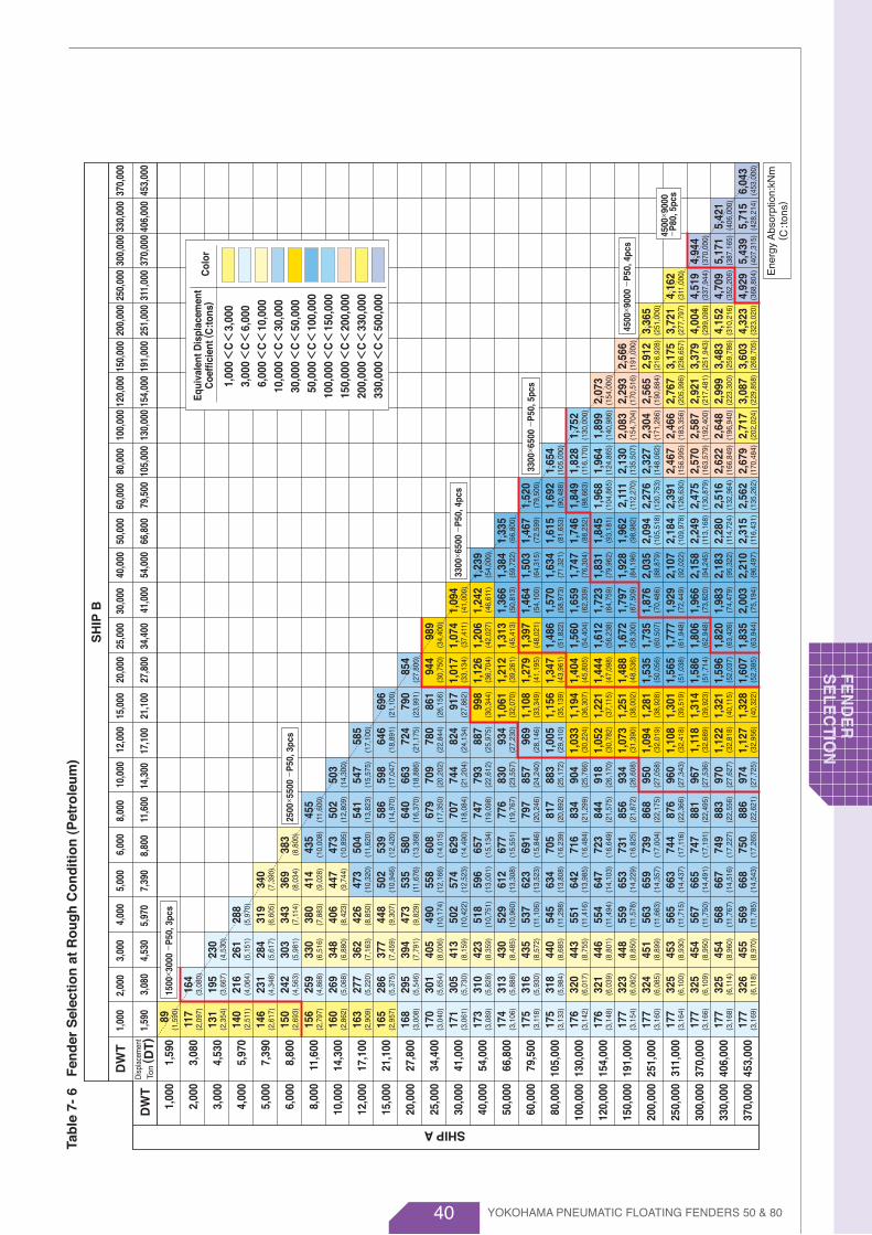
40
Tab
le 7
- 6
Fen
der
Sel
ecti
on
at
Ro
ug
h C
on
dit
ion
(P
etro
leu
m)
SH
IP B
DW
T
Ton ( D
T)
DW
TDi
spla
cem
ent
SHIP A
1,00
0
2,00
0
3,00
0
4,00
0
5,00
0
6,00
0
8,00
0
10,0
00
12,0
00
15,0
00
20,0
00
25,0
00
30,0
00
40,0
00
50,0
00
60,0
00
80,0
00
100,
000
120,
000
150,
000
200,
000
250,
000
300,
000
330,
000
370,
000
1,59
0
3,08
0
4,53
0
5,97
0
7,39
0
8,80
0
11,6
00
14,3
00
17,1
00
21,1
00
27,8
00
34,4
00
41,0
00
54,0
00
66,8
00
79,5
00
105,
000
130,
000
154,
000
191,
000
251,
000
311,
000
370,
000
406,
000
453,
000
1,00
0
1,59
0
89
117
131
140
146
150
156
160
163
165
168
170
171
173
174
175
175
176
176
177
177
177
177
177
177
(1,5
90)
(2,0
97)
(2,3
54)
(2,5
11)
(2,6
17)
(2,6
93)
(2,7
97)
(2,8
62)
(2,9
09)
(2,9
57)
(3,0
08)
(3,0
40)
(3,0
61)
(3,0
89)
(3,1
06)
(3,1
18)
(3,1
33)
(3,1
42)
(3,1
48)
(3,1
54)
(3,1
60)
(3,1
64)
(3,1
66)
(3,1
68)
(3,1
69)
164
195
216
231
242
259
269
277
286
295
301
305
310
313
316
318
320
321
323
324
325
325
325
326
(3,0
80)
(3,6
67)
(4,0
64)
(4,3
48)
(4,5
63)
(4,8
68)
(5,0
68)
(5,2
20)
(5,3
75)
(5,5
46)
(5,6
54)
(5,7
30)
(5,8
28)
(5,8
88)
(5,9
30)
(5,9
84)
(6,0
17)
(6,0
39)
(6,0
62)
(6,0
85)
(6,1
00)
(6,1
09)
(6,1
14)
(6,1
18)
230
261
284
303
330
348
362
377
394
405
413
423
430
435
440
443
446
448
451
453
454
454
455
(4,5
30)
(5,1
51)
(5,6
17)
(5,9
81)
(6,5
16)
(6,8
80)
(7,1
63)
(7,4
59)
(7,7
91)
(8,0
06)
(8,1
59)
(8,3
59)
(8,4
85)
(8,5
72)
(8,6
85)
(8,7
55)
(8,8
01)
(8,8
50)
(8,8
99)
(8,9
30)
(8,9
50)
(8,9
60)
(8,9
70)
288
319
343
380
406
426
448
473
490
502
518
529
537
545
551
554
559
563
565
567
568
569
(5,9
70)
(6,6
05)
(7,1
14)
(7,8
83)
(8,4
23)
(8,8
50)
(9,3
07)
(9,8
29)
(10,
174)
(10,
422)
(10,
751)
(10,
960)
(11,
106)
(11,
298)
(11,
416)
(11,
494)
(11,
578)
(11,
663)
(11,
715)
(11,
750)
(11,
767)
(11,
785)
340
369
414
447
473
502
535
558
574
596
612
623
634
642
647
653
659
663
665
667
668
(7,3
90)
(8,0
34)
(9,0
28)
(9,7
44)
(10,
320)
(10,
946)
(11,
676)
(12,
166)
(12,
523)
(13,
001)
(13,
308)
(13,
523)
(13,
808)
(13,
985)
(14,
103)
(14,
229)
(14,
357)
(14,
437)
(14,
491)
(14,
516)
(14,
543)
383
435
473
504
539
580
608
629
657
677
691
705
716
723
731
739
744
747
749
750
(8,8
00)
(10,
008)
(10,
895)
(11,
620)
(12,
420)
(13,
368)
(14,
015)
(14,
490)
(15,
134)
(15,
551)
(15,
846)
(16,
239)
(16,
484)
(16,
649)
(16,
825)
(17,
004)
(17,
116)
(17,
191)
(17,
227)
(17,
265)
455
502
541
586
640
679
707
747
776
797
817
834
844
856
868
876
881
883
886
(11,
600)
(12,
809)
(13,
823)
(14,
970)
(16,
370)
(17,
350)
(18,
084)
(19,
098)
(19,
767)
(20,
246)
(20,
892)
(21,
299)
(21,
575)
(21,
872)
(22,
175)
(22,
366)
(22,
495)
(22,
556)
(22,
621)
503
547
598
663
709
744
793
830
857
883
904
918
934
950
960
967
970
974
(14,
300)
(15,
575)
(17,
047)
(18,
886)
(20,
202)
(21,
204)
(22,
612)
(23,
557)
(24,
240)
(25,
172)
(25,
766)
(26,
170)
(26,
608)
(27,
058)
(27,
343)
(27,
536)
(27,
627)
(27,
725)
585
646
724
780
824
887
934
969
1,00
5
1,03
3
1,05
2
1,07
3
1,09
4
1,10
8
1,11
8
1,12
2
1,12
7
(17,
100)
(18,
891)
(21,
175)
(22,
844)
(24,
134)
(25,
975)
(27,
230)
(28,
146)
(29,
410)
(30,
224)
(30,
782)
(31,
390)
(32,
019)
(32,
418)
(32,
689)
(32,
818)
(32,
956)
696
790
861
917
998
1,06
1
1,10
8
1,15
6
1,19
4
1,22
1
1,25
1
1,28
1
1,30
1
1,31
4
1,32
1
1,32
8
(21,
100)
(23,
991)
(26,
156)
(27,
862)
(30,
344)
(32,
070)
(33,
349)
(35,
139)
(36,
307)
(37,
115)
(38,
002)
(38,
928)
(39,
519)
(39,
923)
(40,
115)
(40,
322)
854
944
1,01
7
1,12
6
1,21
2
1,27
9
1,34
7
1,40
4
1,44
4
1,48
8
1,53
5
1,56
5
1,58
6
1,59
6
1,60
7
(27,
800)
(30,
750)
(33,
134)
(36,
704)
(39,
261)
(41,
195)
(43,
961)
(45,
805)
(47,
098)
(48,
536)
(50,
056)
(51,
038)
(51,
714)
(52,
037)
(52,
385)
989
1,07
4
1,20
6
1,31
3
1,39
7
1,48
6
1,56
0
1,61
2
1,67
2
1,73
5
1,77
7
1,80
6
1,82
0
1,83
5
(34,
400)
(37,
411)
(42,
027)
(45,
413)
(48,
021)
(51,
822)
(54,
404)
(56,
238)
(58,
300)
(60,
507)
(61,
948)
(62,
948)
(63,
426)
(63,
944)
1,09
4
1,24
2
1,36
6
1,46
4
1,57
0
1,65
9
1,72
3
1,79
7
1,87
6
1,92
9
1,96
6
1,98
3
2,00
3
(41,
000)
(46,
611)
(50,
813)
(54,
100)
(58,
973)
(62,
339)
(64,
759)
(67,
509)
(70,
486)
(72,
449)
(73,
820)
(74,
479)
(75,
194)
1,23
9
1,38
4
1,50
3
1,63
4
1,74
7
1,83
1
1,92
8
2,03
5
2,10
7
2,15
8
2,18
3
2,21
0
(54,
000)
(59,
722)
(64,
315)
(71,
321)
(76,
304)
(79,
962)
(84,
196)
(88,
879)
(92,
022)
(94,
245)
(95,
322)
(96,
497)
1,33
5
1,46
7
1,61
5
1,74
6
1,84
5
1,96
2
2,09
4
2,18
4
2,24
9
2,28
0
2,31
5
(66,
800)
(72,
599)
(81,
653)
(88,
252)
(93,
181)
(98,
982)
(105
,518
)
(109
,978
)
(113
,168
)
(114
,724
)
(116
,431
)
1,52
0
1,69
2
1,84
9
1,96
8
2,11
1
2,27
6
2,39
1
2,47
5
2,51
6
2,56
2
(79,
500)
(90,
488)
(98,
663)
(104
,865
)
(112
,270
)
(120
,753
)
(126
,630
)
(130
,879
)
(132
,964
)
(135
,262
)
1,65
4
1,82
8
1,96
4
2,13
0
2,32
7
2,46
7
2,57
0
2,62
2
2,67
9
(105
,000
)
(116
,170
)
(124
,865
)
(135
,507
)
(148
,062
)
(156
,995
)
(163
,579
)
(166
,849
)
(170
,484
)
1,75
2
1,89
9
2,08
3
2,30
4
2,46
6
2,58
7
2,64
8
2,71
7
(130
,000
)
(140
,986
)
(154
,704
)
(171
,286
)
(183
,356
)
(192
,400
)
(196
,940
)
(202
,024
)
2,07
3
2,29
3
2,56
5
2,76
7
2,92
1
2,99
9
3,08
7
(154
,000
)
(170
,516
)
(190
,884
)
(205
,996
)
(217
,481
)
(223
,300
)
(229
,858
)
2,56
6
2,91
2
3,17
5
3,37
9
3,48
3
3,60
3
(191
,000
)
(216
,928
)
(236
,657
)
(251
,943
)
(259
,786
)
(268
,705
)
3,36
5
3,72
1
4,00
4
4,15
2
4,32
3
(251
,000
)
(277
,797
)
(299
,098
)
(310
,216
)
(323
,020
)
4,16
2
4,51
9
4,70
9
4,92
9
(311
,000
)
(337
,944
)
(352
,206
)
(368
,804
)
4,94
4
5,17
1
5,43
9
(370
,000
)
(387
,165
)
(407
,315
)
5,42
1
5,71
5 (4
06,0
00)
(428
,214
)6,
043
(453
,000
)
2,00
0
3,08
0
3,00
0
4,53
0
4,00
0
5,97
0
5,00
0
7,39
0
6,00
0
8,80
0
8,00
0
11,6
00
10,0
00
14,3
00
12,0
00
17,1
00
15,0
00
21,1
00
20,0
00
27,8
00
25,0
00
34,4
00
30,0
00
41,0
00
40,0
00
54,0
00
50,0
00
66,8
00
60,0
00
79,5
00
80,0
00
105,
000
100,
000
130,
000
120,
000
154,
000
150,
000
191,
000
200,
000
251,
000
250,
000
311,
000
300,
000
370,
000
330,
000
406,
000
370,
000
453,
000
1500×
3000
-P
50, 3
pcs
2500×
5500
-P
50, 3
pcs
3300×
6500
-P
50, 4
pcs
3300×
6500
-P
50, 5
pcs
4500×
9000
-P
50, 4
pcs
1,00
03,
000
6,00
010
,000
30,0
0050
,000
100,
000
150,
000
200,
000
330,
000
3,00
06,
000
10,0
0030
,000
50,0
0010
0,00
015
0,00
020
0,00
033
0,00
050
0,00
0
<C<
<C<
<C<
<C<
<C<
<C<
<C<
<C<
<C<
<C<
Col
orE
quiv
alen
t Dis
plac
emen
tC
oeff
icie
nt ( C
:ton
s)
4500×
9000
-
P80
, 5pc
s
YOKOHAMA PNEUMATIC FLOATING FENDERS 50 & 80
FEN
DE
RS
ELE
CTIO
N
Ene
rgy
Abs
orpt
ion:
kNm
( C:t
ons)
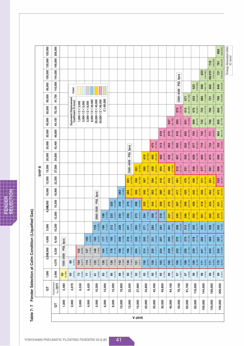
41
Tab
le 7
- 7
Fen
der
Sel
ecti
on
at
Cal
m C
on
dit
ion
(L
iqu
efie
d G
as)
SH
IP B
Ton ( D
T)
GT
GT
Dis
plac
emen
t
SHIP A
1,00
0
2,00
0
3,00
0
4,00
0
5,00
0
6,00
0
8,00
0
10,0
00
12,0
00
15,0
00
20,0
00
25,0
00
30,0
00
40,0
00
50,0
00
60,0
00
80,0
00
100,
000
120,
000
150,
000
2,48
0
4,57
0
6,53
0
8,42
0
10,2
00
12,0
00
15,5
00
18,9
00
22,2
00
27,0
00
34,8
00
42,4
00
49,8
00
64,1
00
78,1
00
91,7
00
118,
000
144,
000
169,
000
206,
000
1,00
0
2,48
0 2,
000
4,57
0
3,00
0
6,53
0
4,00
0
8,42
0
5,00
0
10,2
00
6,
000
12,0
00
8,00
0
15,5
00
10,0
00
18,9
00
12,0
00
22,2
00
15,0
00
27,0
00
20,0
00
34,8
00
25,0
00
42,4
00
30,0
00
49,8
00
40,0
00
64,1
00
50,0
00
78,1
00
60,0
00
91,7
00
80,0
00
118,
000
100,
000
144,
000
120,
000
169,
000
150,
000
206,
000
50 65 73 77 81 83 86 88 90 92 93 95 95 96 97 97 98 98 99 99
(2,4
80)
(3,2
15)
(3,5
95)
(3,8
31)
(3,9
90)
(4,1
10)
(4,2
76)
(4,3
85)
(4,4
62)
(4,5
43)
(4,6
30)
(4,6
86)
(4,7
25)
(4,7
75)
(4,8
07)
(4,8
29)
(4,8
58)
(4,8
76)
(4,8
88)
(4,9
01)
88 104
114
122
128
136
142
146
151
156
159
162
165
166
168
169
171
171
172
(4,5
70)
(5,3
77)
(5,9
24)
(6,3
12)
(6,6
19)
(7,0
59)
(7,3
60)
(7,5
80)
(7,8
17)
(8,0
79)
(8,2
51)
(8,3
72)
(8,5
32)
(8,6
35)
(8,7
06)
(8,7
99)
(8,8
59)
(8,8
99)
(8,9
42)
122
137
148
164
178
188
196
204
214
220
224
229
233
236
239
241
243
245
(6,5
30)
(7,3
56)
(7,9
62)
(8,4
58)
(9,1
89)
(9,7
06)
(10,
092)
(10,
517)
(10,
997)
(11,
317)
(11,
546)
(11,
853)
(12,
052)
(12,
192)
(12,
375)
(12,
493)
(12,
574)
(12,
659)
150
165
177
195
208
218
229
242
251
257
265
270
273
278
282
284
287
(8,4
20)
(9,2
25)
(9,8
96)
(10,
912)
(11,
650)
(12,
209)
(12,
837)
(13,
559)
(14,
050)
(14,
405)
(14,
885)
(15,
201)
(15,
424)
(15,
718)
(15,
910)
(16,
041)
(16,
179)
176
190
212
228
241
255
271
283
291
301
308
313
320
325
328
332
(10,
200)
(11,
027)
(12,
304)
(13,
249)
(13,
978)
(14,
806)
(15,
776)
(16,
444)
(16,
932)
(17,
599)
(18,
043)
(18,
358)
(18,
777)
(19,
051)
(19,
239)
(19,
438)
198
223
242
256
273
294
308
318
331
340
346
355
361
365
370
(12,
000)
(13,
527)
(14,
680)
(15,
579)
(16,
615)
(17,
846)
(18,
706)
(19,
340)
(20,
216)
(20,
804)
(21,
223)
(21,
785)
(22,
154)
(22,
409)
(22,
679)
235
258
276
298
325
344
358
375
387
396
409
418
424
431
(15,
500)
(17,
032)
(18,
255)
(19,
694)
(21,
447)
(22,
701)
(23,
642)
(24,
964)
(25,
866)
(26,
518)
(27,
401)
(27,
987)
(28,
396)
(28.
831)
263
284
309
340
363
380
402
417
429
445
456
464
473
(18,
900)
(20,
418)
(22,
235)
(24,
496)
(26,
146)
(27,
401)
(29,
193)
(30,
435)
(31,
341)
(32,
581)
(33,
414)
(33,
998)
(34,
623)
301
330
367
394
416
442
461
476
496
511
521
533
(22,
200)
(24,
366)
(27,
107)
(29,
142)
(30,
710)
(32,
978)
(34,
573)
(35,
746)
(37,
369)
(38,
469)
(39,
245)
(40,
081)
351
395
428
454
488
512
531
558
577
591
606
(27,
000)
(30,
408)
(32,
991)
(35,
016)
(37,
996)
(40,
127)
(41,
717)
(43,
945)
(45,
474)
(46,
561)
(47,
742)
419
460
492
535
567
592
629
655
674
696
(34,
800)
(38,
226)
(40,
970)
(45,
110)
(48,
147)
(50,
453)
(53,
749)
(56,
054)
(57,
715)
(59,
542)
475
513
563
602
632
677
710
734
762
(42,
400)
(45,
803)
(51,
039)
(54,
962)
(57,
988)
(62,
384)
(65,
511)
(67,
792)
(70,
325)
519
575
618
652
704
742
771
804
(49,
800)
(56,
052)
(60,
819)
(64,
546)
(70,
041)
(74,
006)
(76,
931)
(80,
210)
547
593
631
689
732
766
805
(64,
100)
(70,
411)
(75,
455)
(83,
073)
(88,
711)
(92,
946)
(97,
776)
573
613
675
723
760
804
(78,
100)
(84,
355)
(93,
991)
(101
,273
)
(106
,830
)
(113
,260
)
571
633
682
721
766
(91,
700)
(103
,201
)
(112
,048
)
(118
,890
)
(126
,908
)
523
568
605
649
718
781
856
(118
,000
)
(129
,710
)
(138
,969
)
(150
,049
)
623
666.
8797
721
(144
,000
)
(155
,502
)
(169
,509
)
(169
,000
)
(185
,675
)(2
06,0
00)
1500×
3000
-P
50, 3
pcs
2000×
3500
-P
50, 3
pcs
3300×
4500
-P
50, 3
pcs
3300×
4500
-P
50, 4
pcs
1,00
03,
000
5,00
08,
000
20,0
0040
,000
3,00
05,
000
8,00
020
,000
40,0
0080
,000
<C<
<C<
<C<
<C<
<C<
<C<
Col
orE
quiv
alen
t Dis
plac
emen
tC
oeff
icie
nt ( C
:ton
s)
C>
80,0
00
Ene
rgy
Abs
orpt
ion:
kNm
( C:t
ons)
YOKOHAMA PNEUMATIC FLOATING FENDERS 50 & 80
FEN
DE
R
SE
LEC
TIO
N

42
Tab
le 7
- 8
Fen
der
Sel
ecti
on
at
Mo
der
ate
Co
nd
itio
n (
Liq
uef
ied
Gas
)
SH
IP B
Ton ( D
T)
GT
GT
Dis
plac
emen
t
SHIP A
1,00
0
2,00
0
3,00
0
4,00
0
5,00
0
6,00
0
8,00
0
10,0
00
12,0
00
15,0
00
20,0
00
25,0
00
30,0
00
40,0
00
50,0
00
60,0
00
80,0
00
100,
000
120,
000
150,
000
2,48
0
4,57
0
6,53
0
8,42
0
10,2
00
12,0
00
15,5
00
18,9
00
22,2
00
27,0
00
34,8
00
42,4
00
49,8
00
64,1
00
78,1
00
91,7
00
118,
000
144,
000
169,
000
206,
000
1,00
0
2,48
0 2,
000
4,57
0
3,00
0
6,53
0
4,00
0
8,42
0
5,00
0
10,2
00
6,
000
12,0
00
8,00
0
15,5
00
10,0
00
18,9
00
12,0
00
22,2
00
15,0
00
27,0
00
20,0
00
34,8
00
25,0
00
42,4
00
30,0
00
49,8
00
40,0
00
64,1
00
50,0
00
78,1
00
60,0
00
91,7
00
80,0
00
118,
000
100,
000
144,
000
120,
000
169,
000
150,
000
206,
000
89 115
129
137
143
147
153
157
160
163
166
168
170
171
172
173
174
175
175
176
(2,4
80)
(3,2
15)
(3,5
95)
(3,8
31)
(3,9
90)
(4,1
10)
(4,2
76)
(4,3
85)
(4,4
62)
(4,5
43)
(4,6
30)
(4,6
86)
(4,7
25)
(4,7
75)
(4,8
07)
(4,8
29)
(4,8
58)
(4,8
76)
(4,8
88)
(4,9
01)
157
185
204
217
227
242
253
260
269
278
283
288
292
296
298
301
303
305
306
(4,5
70)
(5,3
77)
(5,9
24)
(6,3
12)
(6,6
19)
(7,0
59)
(7,3
60)
(7,5
80)
(7,8
17)
(8,0
79)
(8,2
51)
(8,3
72)
(8,5
32)
(8,6
35)
(8,7
06)
(8,7
99)
(8,8
59)
(8,8
99)
(8,9
42)
214
241
261
277
301
318
330
344
360
370
378
387
393
397
403
407
409
412
(6,5
30)
(7,3
56)
(7,9
62)
(8,4
58)
(9,1
89)
(9,7
06)
(10,
092)
(10,
517)
(10,
997)
(11,
317)
(11,
546)
(11,
853)
(12,
052)
(12,
192)
(12,
375)
(12,
493)
(12,
574)
(12,
659)
264
289
310
342
365
383
402
425
440
451
465
474
480
489
495
499
504
(8,4
20)
(9,2
25)
(9,8
96)
(10,
912)
(11,
650)
(12,
209)
(12,
837)
(13,
559)
(14,
050)
(14,
405)
(14,
885)
(15,
201)
(15,
424)
(15,
718)
(15,
910)
(16,
041)
(16,
179)
306
331
369
397
419
444
473
493
508
525
537
546
558
566
572
578
(10,
200)
(11,
027)
(12,
304)
(13,
249)
(13,
978)
(14,
806)
(15,
776)
(16,
444)
(16,
932)
(17,
599)
(18,
043)
(18,
358)
(18,
777)
(19,
051)
(19,
239)
(19,
438)
343
386
419
444
474
509
533
551
573
588
599
614
625
632
640
(12,
000)
(13,
527)
(14,
680)
(15,
579)
(16,
615)
(17,
846)
(18,
706)
(19,
340)
(20,
216)
(20,
804)
(21,
223)
(21,
785)
(22,
154)
(22,
409)
(22,
679)
403
443
475
512
557
590
614
644
665
681
702
717
728
740
(15,
500)
(17,
032)
(18,
255)
(19,
694)
(21
,447
)
(22,
701)
(23,
642)
(24,
964)
(25,
866)
(26,
518)
(27,
401)
(27,
987)
(28,
396)
(28,
831)
444
479
522
574
613
642
679
705
724
751
770
784
799
(18,
900)
(20,
418)
(22,
235)
(24,
496)
(26,
146)
(27,
401)
(29,
193)
(30,
435)
(31,
341)
(32,
581)
(33,
414)
(33,
998)
(34,
623)
505
554
616
662
697
742
774
798
833
857
874
894
(22,
200)
(24,
366)
(27,
107)
(29,
142)
(30,
710)
(32,
978)
(34,
573)
(35,
746)
(37,
369)
(38,
469)
(39,
245)
(40,
081)
587
661
716
760
816
857
888
933
965
988
1,01
4
(27,
000)
(30,
408)
(32,
991)
(35,
016)
(37,
996)
(40,
127)
(41,
717)
(43,
945)
(45,
474)
(46,
561)
(47,
742)
(34,
800)
(38,
226)
(40,
970)
(45,
110)
(48,
147)
(50,
453)
(53,
749)
(56,
054)
(57,
715)
(59,
542)
694
762
816
887
941
982
1,04
2
1,08
6
1,11
8
1,15
4
778
841
923
986
1,03
6
1,10
9
1,16
3
1,20
3
1,24
9
(42,
400)
(45,
803)
(51,
039)
(54,
962)
(57,
988)
(62,
384)
(65,
511)
(67,
792)
(70,
325)
833
923
992
1,04
7
1,13
0
1,17
5
1,23
8
1,29
2
(49,
800)
(56,
052)
(60,
819)
(64,
546)
(70,
041)
(74,
006)
(76,
931)
(80,
210)
854
927
986
1,07
6
1,14
4
1,19
6
1,25
7
(64,
100)
(70,
411)
(75,
455)
(83,
073)
(88,
711)
(92,
946)
(97,
776)
919
982
1,08
2
1,15
8
1,21
8
1,28
8
(78,
100)
(84,
355)
(93,
991)
(101
,273
)
(106
,830
)
(113
,260
)
944
1,04
7
1,12
8
1,19
1
1,26
7
(91,
700)
(103
,201
)
(112
,048
)
(118
,890
)
(126
,908
)
929
1,01
0
1,18
5
1,27
2
(118
,000
)
(129
,710
)
(138
,969
)
(150
,049
)
(144
,000
)
(155
,502
)
(169
,509
)
(169
,000
)
(185
,675
)(2
06,0
00)
1,10
7
1185
.564
1,28
2
1,27
6
1,38
81,
521
1500×
3000
-P
50, 3
pcs
2000×
3500
-P
50, 3
pcs
3300×
4500
-P
50, 3
pcs
3300×
4500
-P
50, 4
pcs
4500×
9000
-P
50, 4
pcs
Ene
rgy
Abs
orpt
ion:
kNm
( C:t
ons)
1,00
03,
000
5,00
08,
000
20,0
0040
,000
3,00
05,
000
8,00
020
,000
40,0
0080
,000
<C<
<C<
<C<
<C<
<C<
<C<
Col
orE
quiv
alen
t Dis
plac
emen
tC
oeff
icie
nt ( C
:ton
s)
C>
80,0
00
YOKOHAMA PNEUMATIC FLOATING FENDERS 50 & 80
FEN
DE
RS
ELE
CTIO
N

43
Tab
le 7
- 9
Fen
der
Sel
ecti
on
at
Ro
ug
h C
on
dit
ion
(L
iqu
efie
d G
as)
SH
IP B
Ton
( DT
)G
T
GT
Dis
plac
emen
t
SHIP A
1,00
0
2,00
0
3,00
0
4,00
0
5,00
0
6,00
0
8,00
0
10,0
00
12,0
00
15,0
00
20,0
00
25,0
00
30,0
00
40,0
00
50,0
00
60,0
00
80,0
00
100,
000
120,
000
150,
000
2,48
0
4,57
0
6,53
0
8,42
0
10,2
00
12,0
00
15,5
00
18,9
00
22,2
00
27,0
00
34,8
00
42,4
00
49,8
00
64,1
00
78,1
00
91,7
00
118,
000
144,
000
169,
000
206,
000
1,00
0
2,48
0
2,00
0
4,57
0
3,00
0
6,53
0
4,00
0
8,42
0
5,00
0
10,2
00 6,
000
12,0
00
8,00
0
15,5
00
10,0
00
18,9
00
12,0
00
22,2
00
15,0
00
27,0
00
20,0
00
34,8
00
25,0
00
42,4
00
30,0
00
49,8
00
40,0
00
64,1
00
50,0
00
78,1
00
60,0
00
91,7
00
80,0
00
118,
000
100,
000
144,
000
120,
000
169,
000
150,
000
206,
000
139
180
201
215
224
230
240
246
250
255
260
263
265
268
269
270
272
273
274
274
(2,4
80)
(3,2
15)
(3,5
95)
(3,8
31)
(3,9
90)
(4,1
10)
(4,2
76)
(4,3
85)
(4,4
62)
(4,5
43)
(4,6
30)
(4,6
86)
(4,7
25)
(4,7
75)
(4,8
07)
(4,8
29)
(4,8
58)
(4,8
76)
(4,8
88)
(4,9
01)
245
288
317
337
354
377
393
405
418
432
441
448
455
460
464
469
472
474
476
(4,5
70)
(5,3
77)
(5,9
24)
(6,3
12)
(6,6
19)
(7,0
59)
(7,3
60)
(7,5
80)
(7,8
17)
(8,0
79)
(8,2
51)
(8,3
72)
(8,5
32)
(8,6
35)
(8,7
06)
(8,7
99)
(8,8
59)
(8,8
99)
(8,9
42)
333
375
406
431
468
495
514
536
561
577
589
602
612
618
627
633
638
642
(6,5
30)
(7,3
56)
(7,9
62)
(8,4
58)
(9,1
89)
(9,7
06)
(10,
092)
(10,
517)
(10,
997)
(11,
317)
(11,
546)
(11,
853)
(12,
052)
(12,
192)
(12,
375)
(12,
493)
(12,
574)
(12,
659)
410
449
481
530
566
593
624
659
683
700
721
734
744
758
767
774
781
(8,4
20)
(9,2
25)
(9,8
96)
(10,
912)
(11,
650)
(12,
209)
(12,
837)
(13,
559)
(14,
050)
(14,
405)
(14,
885)
(15,
201)
(15,
424)
(15,
718)
(15,
910)
(16,
041)
(16,
179)
473
511
570
614
647
685
730
761
784
811
829
843
861
874
883
892
(10,
200)
(11,
027)
(12,
304)
(13,
249)
(13,
978)
(14,
806)
(15,
776)
(16,
444)
(16,
932)
(17,
599)
(18,
043)
(18,
358)
(18,
777)
(19,
051)
(19,
239)
(19,
438)
527
594
644
683
729
783
820
848
882
905
922
945
961
972
985
(12,
000)
(13,
527)
(14,
680)
(15,
579)
(16,
615)
(17,
846)
(18,
706)
(19,
340)
(20,
216)
(20,
804)
(21,
223)
(21,
785)
(22,
154)
(22,
409)
(22,
679)
614
674
723
779
849
898
935
981
1,01
3
1,03
6
1,06
9
1,09
2
1,10
8
1,12
6
(15,
500)
(17,
032)
(18,
255)
(19,
694)
(21
,447
)
(22,
701)
(23,
642)
(24,
964)
(25,
866)
(26,
518)
(27,
401)
(27,
987)
(28,
396)
(28,
831)
672
726
790
870
929
973
1,02
8
1,06
8
1,09
7
1,13
8
1,16
7
1,18
8
1,21
0
(18,
900)
(20,
418)
(22,
235)
(24,
496)
(26,
146)
(27,
401)
(29,
193)
(30,
435)
(31,
341)
(32,
581)
(33,
414)
(33,
998)
(34,
623)
761
835
929
998
1,05
2
1,11
9
1,16
8
1,20
4
1,25
6
1,29
3
1,31
9
1,34
8
(22,
200)
(24,
366)
(27,
107)
(29,
142)
(30,
710)
(32,
978)
(34,
573)
(35,
746)
(37,
369)
(38,
469)
(39,
245)
(40,
081)
879
989
1,07
3
1,13
8
1,22
2
1,28
3
1,33
0
1,39
7
1,44
5
1,47
9
1,51
8
(27,
000)
(30,
408)
(32,
991)
(35,
016)
(37,
996)
(40,
127)
(41,
717)
(43,
945)
(45,
474)
(46,
561)
(47,
742)
1,03
9
1,14
0
1,22
2
1,32
8
1,40
8
1,46
9
1,55
9
1,62
5
1,67
3
1,72
7
(34,
800)
(38,
226)
(40,
970)
(45,
110)
(48,
147)
(50,
453)
(53,
749)
(56,
054)
(57,
715)
(59,
542)
1,15
0
1,24
2
1,36
3
1,45
6
1,52
9
1,63
8
1,71
7
1,77
7
1,84
4
(42,
400)
(45,
803)
(51,
039)
(54,
962)
(57,
988)
(62,
384)
(65,
511)
(67,
792)
(70,
325)
1,22
1
1,35
3
1,45
5
1,53
6
1,65
7
1,74
8
1,81
6
1,89
4
(49,
800)
(56,
052)
(60,
819)
(64,
546)
(70,
041)
(74,
006)
(76,
931)
(80,
210)
1,23
0
1,33
5
1,42
0
1,54
9
1,64
7
1,72
2
1,81
0
(64,
100)
(70,
411)
(75,
455)
(83,
073)
(88,
711)
(92,
946)
(97,
776)
1,34
5
1,43
9
1,58
4
1,69
6
1,78
3
1,88
6
(78,
100)
(84,
355)
(93,
991)
(101
,273
)
(106
,830
)
(113
,260
)
1,41
0
1,56
4
1,68
5
1,77
9
1,89
2
(91,
700)
(103
,201
)
(112
,048
)
(118
,890
)
(126
,908
)
1,45
2
1,57
9
1,68
0
1,80
3
(118
,000
)
(129
,710
)
(138
,969
)
(150
,049
)
1,73
0
1,85
2
2,00
3
(144
,000
)
(155
,502
)
(169
,509
)
1500×
3000
-P
50, 3
pcs
2000×
3500
-P
50, 3
pcs
3300×
4500
-P
50, 3
pcs
3300×
4500
-P
50, 4
pcs
4500×
9000
-P
50, 4
pcs E
nerg
y A
bsor
ptio
n:kN
m( C
:ton
s)
1,99
3
2,16
8
(169
,000
)
(185
,675
)
2,37
7(2
06,0
00)
1,00
03,
000
5,00
08,
000
20,0
0040
,000
3,00
05,
000
8,00
020
,000
40,0
0080
,000
<C<
<C<
<C<
<C<
<C<
<C<
Col
orE
quiv
alen
t Dis
plac
emen
tC
oeff
icie
nt ( C
:ton
s)
C>
80,0
00
YOKOHAMA PNEUMATIC FLOATING FENDERS 50 & 80
FEN
DE
R
SE
LEC
TIO
N
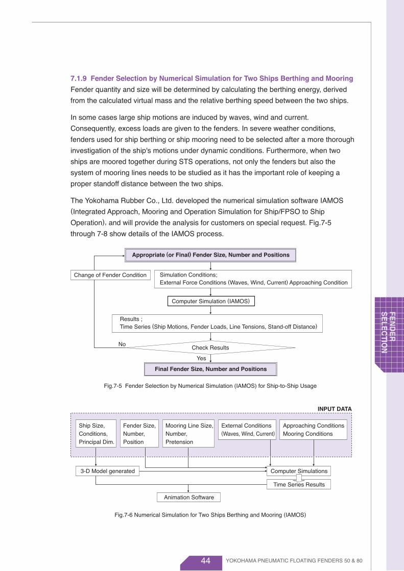
44
7.1.9 Fender Selection by Numerical Simulation for Two Ships Berthing and Mooring
Fender quantity and size will be determined by calculating the berthing energy, derived
from the calculated virtual mass and the relative berthing speed between the two ships.
In some cases large ship motions are induced by waves, wind and current.
Consequently, excess loads are given to the fenders. In severe weather conditions,
fenders used for ship berthing or ship mooring need to be selected after a more thorough
investigation of the ship's motions under dynamic conditions. Furthermore, when two
ships are moored together during STS operations, not only the fenders but also the
system of mooring lines needs to be studied as it has the important role of keeping a
proper standoff distance between the two ships.
The Yokohama Rubber Co., Ltd. developed the numerical simulation software IAMOS (Integrated Approach, Mooring and Operation Simulation for Ship/FPSO to Ship
Operation), and will provide the analysis for customers on special request. Fig.7-5
through 7-8 show details of the IAMOS process.
Fig.7-5 Fender Selection by Numerical Simulation (IAMOS) for Ship-to-Ship Usage
Fig.7-6 Numerical Simulation for Two Ships Berthing and Mooring (IAMOS)
INPUT DATA
Check Results
Mooring Line Size,Number, Pretension
Fender Size,Number, Position
Ship Size,Conditions,Principal Dim.
External Conditions(Waves, Wind, Current)
Approaching ConditionsMooring Conditions
Appropriate (or Final) Fender Size, Number and Positions
Final Fender Size, Number and Positions
Computer Simulation (IAMOS)
Simulation Conditions;External Force Conditions (Waves, Wind, Current) Approaching Condition
Results ;Time Series (Ship Motions, Fender Loads, Line Tensions, Stand-off Distance)
No
Yes
Change of Fender Condition
3-D Model generated Computer Simulations
Time Series Results
Animation Software
YOKOHAMA PNEUMATIC FLOATING FENDERS 50 & 80
FEN
DE
RS
ELE
CTIO
N
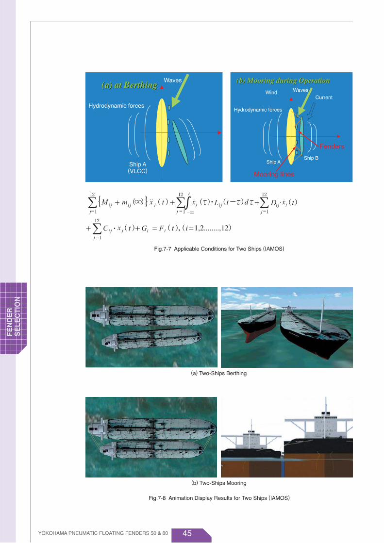
45
(b) Mooring during Operation(a) at Berthing(a) at Berthing (b) Mooring during OperationWaves
Hydrodynamic forces
Ship A(VLCC)
Hydrodynamic forces
Ship AShip B
Wind WavesCurrent
Fenders
Mooring Iines
Fig.7-7 Applicable Conditions for Two Ships (IAMOS)
Fig.7-8 Animation Display Results for Two Ships (IAMOS)
(a) Two-Ships Berthing
(b) Two-Ships Mooring
YOKOHAMA PNEUMATIC FLOATING FENDERS 50 & 80
FEN
DE
R
SE
LEC
TIO
N
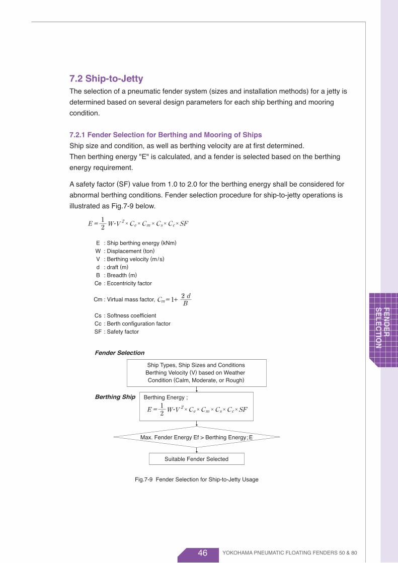
46
7.2 Ship-to-Jetty The selection of a pneumatic fender system (sizes and installation methods) for a jetty is
determined based on several design parameters for each ship berthing and mooring
condition.
7.2.1 Fender Selection for Berthing and Mooring of Ships
Ship size and condition, as well as berthing velocity are at first determined.
Then berthing energy "E" is calculated, and a fender is selected based on the berthing
energy requirement.
A safety factor (SF) value from 1.0 to 2.0 for the berthing energy shall be considered for
abnormal berthing conditions. Fender selection procedure for ship-to-jetty operations is
illustrated as Fig.7-9 below.
Fig.7-9 Fender Selection for Ship-to-Jetty Usage
Max. Fender Energy Ef > Berthing Energy ; E
Suitable Fender Selected
EWVdB
Ce
Cm
CsCcSF
: Ship berthing energy (kNm)
: Displacement (ton)
: Berthing velocity (m/s)
: draft (m)
: Breadth (m)
: Eccentricity factor
: Virtual mass factor,
: Softness coefficient: Berth configuration factor: Safety factor
Fender Selection
Berthing Ship
Ship Types, Ship Sizes and ConditionsBerthing Velocity (V) based on Weather Condition (Calm, Moderate, or Rough)
Berthing Energy ;
W・V 2E = Ce SF21
× Cm× Cs× Cc× ×
W・V 2E = Ce SF21
× Cm× Cs× Cc× ×
+Cm= 2・1 dB
YOKOHAMA PNEUMATIC FLOATING FENDERS 50 & 80
FEN
DE
RS
ELE
CTIO
N

47
7.2.2 Berthing Energy Tables
Tables 7-11 through 7-17 show the berthing energy for various kinds of ships and sizes
at different approaching speeds corresponding to Calm, Moderate and Rough weather
conditions as shown in Table 7-10.
In the tables, a safety factor SF=1.0 is used, and if a higher SF value is to be considered,
the energy value is to be multiplied by the desired SF.
Table 7-10 shows figures for tankers, but it can be applied to other kinds of ships, if their
virtual weights correspond to those in the table.
Table 7-10 Berthing Velocity for Ship-to-Jetty Operations
Less than 10,000
10,000- 50,000
50,000-100,000
Over 100,000
Calm
Calm condition Moderate condition Rough condition
DWT RoughModerate
0.40 m/s -0.30 m/s -0.20 m/s -0.20 m/s -
0.18 - 0.30 m/s
0.15 - 0.25 m/s
0.12 - 0.18 m/s
0.12 - 0.18 m/s
- 0.15 m/s
- 0.12 m/s
- 0.10 m/s
- 0.10 m/s
Table 7-11 Berthing Energy for Oil Tanker (kNm)
0.10 0.12 0.15 0.18 0.20 0.25 0.30 0.40
7.1
13.7
20.1
26.4
32.7
38.8
51.1
62.8
75.0
92.4
121
150
179
235
297
362
454
561
663
821
1,077
1,332
1,582
1,735
1,934
10.3
19.8
29.0
38.1
47.0
55.9
73.5
90.5
108
133
175
216
257
338
427
521
653
807
955
1,183
1,550
1,918
2,278
2,498
2,785
16.0
30.9
45.2
59.5
73.5
87.4
115
141
169
208
273
338
402
528
668
814
1,021
1,262
1,492
1,848
2,423
2,996
3,560
3,903
4,351
23.1
44.4
65.1
85.6
106
126
165
204
243
299
394
486
579
760
961
1,171
1,470
1,817
2,149
2,661
3,488
4,315
5,126
5,620
6,265
28.5
54.9
80.4
106
131
155
204
251
300
370
486
600
714
939
1,187
1,446
1,815
2,243
2,653
3,285
4,307
5,327
6,328
6,939
7,735
44.5
85.7
126
165
204
243
319
393
469
578
759
938
1,116
1,466
1,855
2,260
2,836
3,505
4,146
5,132
6,729
8,323
9,888
10,842
12,086
64.1
123
181
238
294
350
460
566
675
832
1,093
1,350
1,607
2,112
2,671
3,254
4,083
5,047
5,970
7,391
9,690
11,985
14,239
15,612
17,404
114
219
322
423
523
621
817
1,005
1,201
1,479
1,944
2,401
2,857
3,754
4,748
5,785
7,259
8,972
10,613
13,139
17,227
21,307
25,313
27,755
30,940
1,000
2,000
3,000
4,000
5,000
6,000
8,000
10,000
12,000
15,000
20,000
25,000
30,000
40,000
50,000
60,000
80,000
100,000
120,000
150,000
200,000
250,000
300,000
330,000
370,000
2,849
5,486
8,042
10,573
13,064
15,533
20,427
25,136
30,013
36,966
48,590
60,017
71,427
93,856
118,692
144,622
181,483
224,293
265,315
328,475
430,676
532,685
632,829
693,880
773,508
DWTV (m /s)
VW ( T )
YOKOHAMA PNEUMATIC FLOATING FENDERS 50 & 80
FEN
DE
R
SE
LEC
TIO
N

48
Calm condition Moderate condition Rough condition
Table 7-13 Berthing Energy for Bulk Carrier (kNm)
0.10 0.12 0.15 0.18 0.20 0.25 0.30 0.40
6.9
13.2
19.4
25.4
31.3
37.1
48.7
59.8
71.0
88.0
115
142
168
221
270
329
424
523
620
766
1,003
1,235
1,467
9.9
19.0
27.9
36.6
45.0
53.5
70.1
86.2
102
127
166
204
243
318
389
474
610
754
893
1,102
1,444
1,779
2,113
15.5
29.8
43.6
57.1
70.4
83.6
109
135
160
198
259
319
379
497
608
740
953
1,178
1,396
1,722
2,256
2,779
3,301
22.3
42.9
62.7
82.2
101
120
158
194
230
285
373
459
546
715
876
1,066
1,373
1,696
2,010
2,480
3,249
4,002
4,754
27.6
52.9
77.4
102
125
149
195
239
284
352
461
567
674
883
1,081
1,316
1,695
2,094
2,481
3,062
4,011
4,941
5,869
43.1
82.7
121
159
195
232
304
374
444
550
720
886
1,053
1,380
1,690
2,056
2,648
3,271
3,877
4,784
6,267
7,720
9,171
62.0
119
174
228
281
334
438
539
639
792
1,036
1,276
1,516
1,987
2,433
2,961
3,814
4,711
5,583
6,890
9,024
11,116
13,206
110
212
310
406
500
594
779
957
1,136
1,407
1,842
2,269
2,696
3,533
4,326
5,264
6,780
8,375
9,925
12,248
16,043
19,762
23,477
1,000
2,000
3,000
4,000
5,000
6,000
8,000
10,000
12,000
15,000
20,000
25,000
30,000
40,000
50,000
60,000
80,000
100,000
120,000
150,000
200,000
250,000
300,000
2,757
5,290
7,743
10,154
12,508
14,859
19,464
23,936
28,403
35,185
46,054
56,728
67,389
88,325
108,145
131,611
169,503
209,372
248,131
306,202
401,077
494,051
586,918
DWTV (m /s)
VW ( T )
Table 7-12 Berthing Energy for Gas Carrier (kNm)
0.10 0.12 0.15 0.18 0.20 0.25 0.30 0.40
11.0
20.5
29.2
37.6
45.5
53.5
69.0
84.0
98.6
120
154
188
220
273
324
373
465
554
16.0
29.5
42.0
54.1
65.5
77.0
99.3
121
142
173
222
270
317
394
467
537
669
797
25.1
46.0
65.7
84.5
102
120
155
189
222
270
347
422
496
615
730
839
1,045
1,246
36.1
66.3
94.5
122
147
173
223
272
319
388
500
608
714
886
1,051
1,208
1,505
1,794
44.5
81.8
117
150
182
214
276
336
394
479
617
751
881
1,094
1,297
1,491
1,858
2,215
69.6
128
182
235
284
334
431
525
616
749
964
1,173
1,377
1,709
2,027
2,330
2,904
3,461
100
184
263
338
409
481
621
756
887
1,078
1,388
1,689
1,983
2,461
2,919
3,355
4,181
4,983
178
327
467
601
728
855
1,103
1,344
1,578
1,917
2,467
3,003
3,525
4,375
5,189
5,965
7,433
8,859
1,000
2,000
3,000
4,000
5,000
6,000
8,000
10,000
12,000
15,000
20,000
25,000
30,000
40,000
50,000
60,000
80,000
100,000
4,454
8,183
11,672
15,031
18,191
21,384
27,586
33,604
39,440
47,921
61,687
75,086
88,121
109,372
129,723
149,117
185,834
221,472
GTV (m /s)
VW ( T )
YOKOHAMA PNEUMATIC FLOATING FENDERS 50 & 80
FEN
DE
RS
ELE
CTIO
N
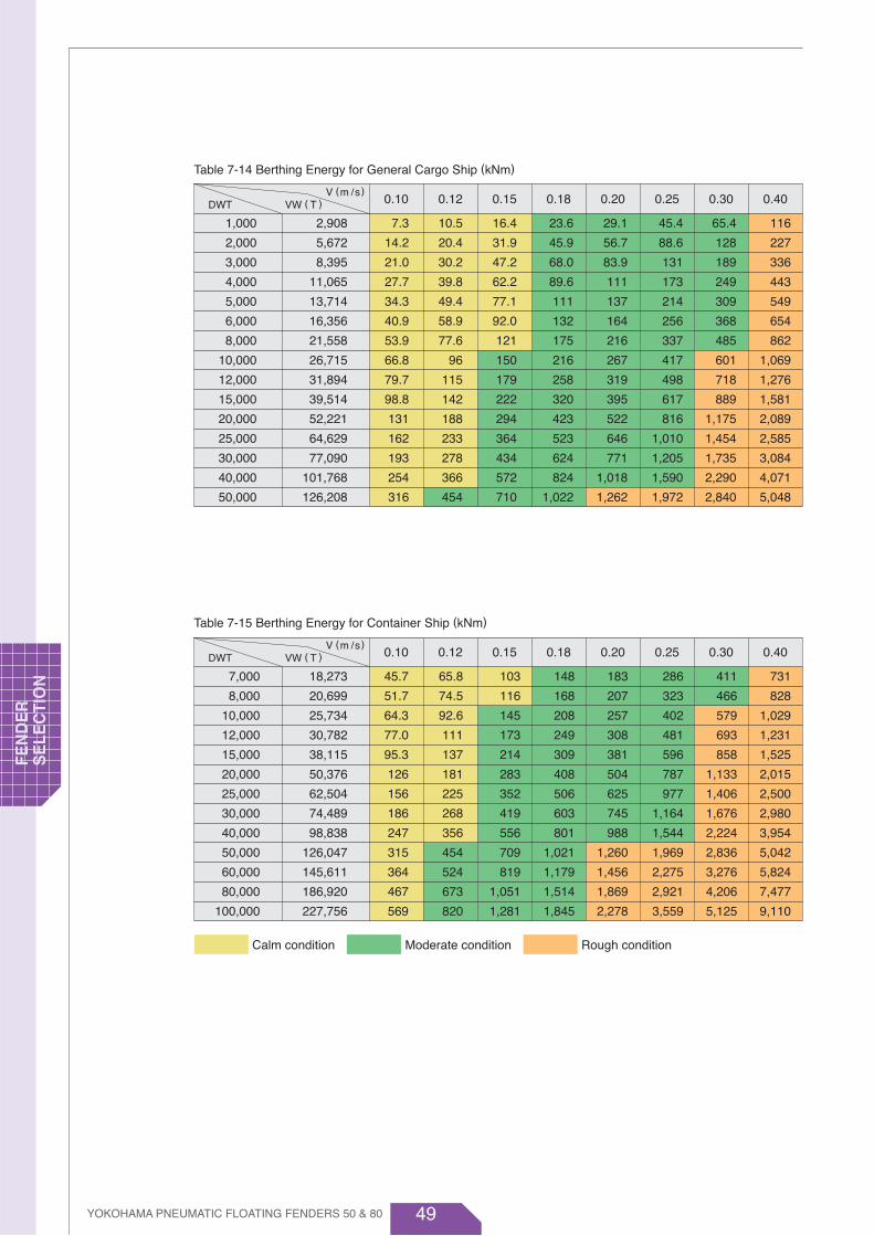
49
Calm condition Moderate condition Rough condition
Table 7-15 Berthing Energy for Container Ship (kNm)
0.10 0.12 0.15 0.18 0.20 0.25 0.30 0.40
45.7
51.7
64.3
77.0
95.3
126
156
186
247
315
364
467
569
65.8
74.5
92.6
111
137
181
225
268
356
454
524
673
820
103
116
145
173
214
283
352
419
556
709
819
1,051
1,281
148
168
208
249
309
408
506
603
801
1,021
1,179
1,514
1,845
183
207
257
308
381
504
625
745
988
1,260
1,456
1,869
2,278
286
323
402
481
596
787
977
1,164
1,544
1,969
2,275
2,921
3,559
411
466
579
693
858
1,133
1,406
1,676
2,224
2,836
3,276
4,206
5,125
731
828
1,029
1,231
1,525
2,015
2,500
2,980
3,954
5,042
5,824
7,477
9,110
7,000
8,000
10,000
12,000
15,000
20,000
25,000
30,000
40,000
50,000
60,000
80,000
100,000
18,273
20,699
25,734
30,782
38,115
50,376
62,504
74,489
98,838
126,047
145,611
186,920
227,756
DWTV (m /s)
VW ( T )
Table 7-14 Berthing Energy for General Cargo Ship (kNm)
0.10 0.12 0.15 0.18 0.20 0.25 0.30 0.40
7.3
14.2
21.0
27.7
34.3
40.9
53.9
66.8
79.7
98.8
131
162
193
254
316
10.5
20.4
30.2
39.8
49.4
58.9
77.6
96
115
142
188
233
278
366
454
16.4
31.9
47.2
62.2
77.1
92.0
121
150
179
222
294
364
434
572
710
23.6
45.9
68.0
89.6
111
132
175
216
258
320
423
523
624
824
1,022
29.1
56.7
83.9
111
137
164
216
267
319
395
522
646
771
1,018
1,262
45.4
88.6
131
173
214
256
337
417
498
617
816
1,010
1,205
1,590
1,972
65.4
128
189
249
309
368
485
601
718
889
1,175
1,454
1,735
2,290
2,840
116
227
336
443
549
654
862
1,069
1,276
1,581
2,089
2,585
3,084
4,071
5,048
1,000
2,000
3,000
4,000
5,000
6,000
8,000
10,000
12,000
15,000
20,000
25,000
30,000
40,000
50,000
2,908
5,672
8,395
11,065
13,714
16,356
21,558
26,715
31,894
39,514
52,221
64,629
77,090
101,768
126,208
DWTV (m /s)
VW ( T )
YOKOHAMA PNEUMATIC FLOATING FENDERS 50 & 80
FEN
DE
R
SE
LEC
TIO
N

50
Calm condition Moderate condition Rough condition
Table 7-17 Berthing Energy for Ferry (kNm)
0.10 0.12 0.15 0.18 0.20 0.25 0.30 0.40
4.6
9.1
13.7
18.2
22.7
27.3
36.3
45.3
54.3
68.0
90.4
113
135
181
6.6
13.2
19.7
26.2
32.7
39.2
52.3
65.2
78.1
97.9
130
163
195
260
10.3
20.6
30.8
40.9
51.2
61.3
81.7
102
122
153
203
254
305
407
14.9
29.6
44.3
59.0
73.7
88.3
118
147
176
220
293
366
439
586
18.4
36.5
54.7
72.8
90.9
109
145
181
217
272
362
452
542
723
28.7
57.1
85.4
114
142
170
227
283
339
425
565
706
847
1,130
41.3
82.2
123
164
205
245
327
407
488
612
813
1,016
1,219
1,628
73.5
146
219
291
364
436
581
724
868
1,087
1,446
1,806
2,168
2,893
1,000
2,000
3,000
4,000
5,000
6,000
8,000
10,000
12,000
15,000
20,000
25,000
30,000
40,000
1,838
3,653
5,469
7,278
9,094
10,901
14,529
18,109
21,701
27,184
36,153
45,159
54,194
72,336
GTV (m /s)
VW ( T )
Table 7-16 Berthing Energy for Passenger Ship (kNm)
0.10 0.12 0.15 0.18 0.20 0.25 0.30 0.40
3.7
7.0
10.3
13.5
16.6
19.7
25.9
32.0
38.0
46.8
61.7
73.7
85.2
107
128
148
187
5.3
10.1
14.8
19.4
24.0
28.4
37.3
46.1
54.7
67.5
88.8
106
123
154
185
214
270
8.3
15.8
23.2
30.3
37.4
44.4
58.3
72.0
85.5
105
139
166
192
241
288
334
422
11.9
22.7
33.4
43.7
53.9
63.9
83.9
104
123
152
200
239
276
347
415
481
607
14.7
28.1
41.2
53.9
66.5
78.9
104
128
152
187
247
295
341
428
513
593
750
22.9
43.9
64.4
84.3
104
123
162
200
238
293
386
461
533
669
801
927
1,171
33.0
63.2
92.7
121
150
178
233
288
342
422
555
664
767
964
1,154
1,335
1,686
58.7
112
165
216
266
316
414
512
608
749
987
1,180
1,363
1,713
2,051
2,374
2,998
1,000
2,000
3,000
4,000
5,000
6,000
8,000
10,000
12,000
15,000
20,000
25,000
30,000
40,000
50,000
60,000
80,000
1,468
2,807
4,120
5,394
6,654
7,895
10,360
12,795
15,207
18,737
24,676
29,492
34,086
42,826
51,283
59,341
74,952
GTV (m /s)
VW ( T )
YOKOHAMA PNEUMATIC FLOATING FENDERS 50 & 80
FEN
DE
RS
ELE
CTIO
N
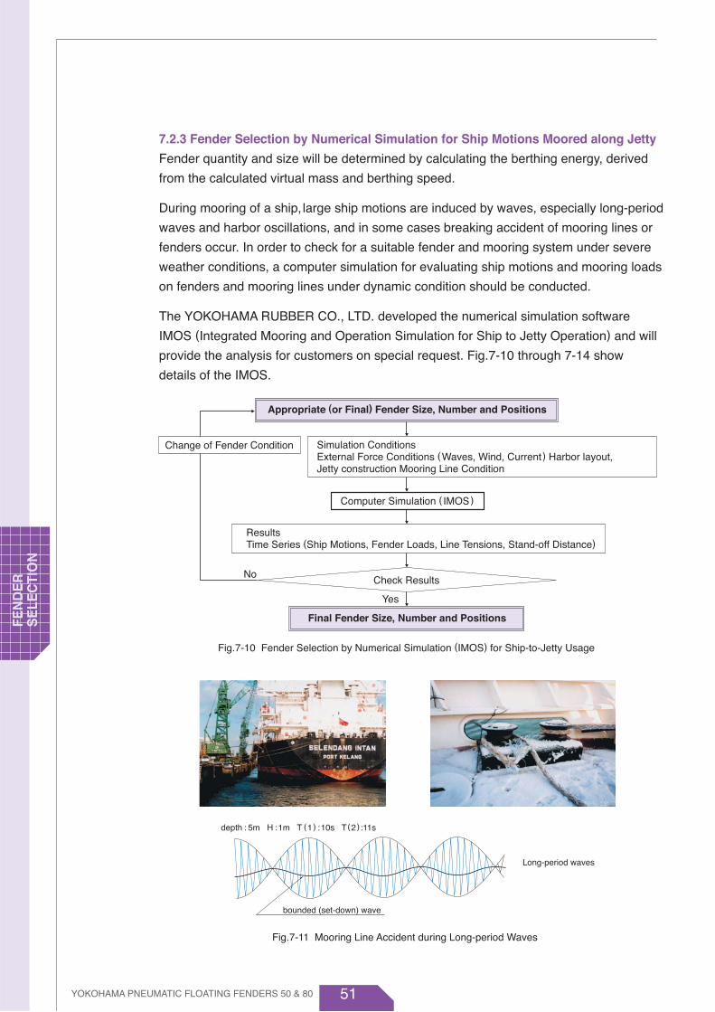
51
Long-period waves
bounded (set-down) wave
depth : 5m H :1m T (1) :10s T(2):11s
7.2.3 Fender Selection by Numerical Simulation for Ship Motions Moored along Jetty
Fender quantity and size will be determined by calculating the berthing energy, derived
from the calculated virtual mass and berthing speed.
During mooring of a ship, large ship motions are induced by waves, especially long-period
waves and harbor oscillations, and in some cases breaking accident of mooring lines or
fenders occur. In order to check for a suitable fender and mooring system under severe
weather conditions, a computer simulation for evaluating ship motions and mooring loads
on fenders and mooring lines under dynamic condition should be conducted.
The YOKOHAMA RUBBER CO., LTD. developed the numerical simulation software
IMOS (Integrated Mooring and Operation Simulation for Ship to Jetty Operation) and will
provide the analysis for customers on special request. Fig.7-10 through 7-14 show
details of the IMOS.
Fig.7-10 Fender Selection by Numerical Simulation (IMOS) for Ship-to-Jetty Usage
Fig.7-11 Mooring Line Accident during Long-period Waves
Check Results
Appropriate (or Final) Fender Size, Number and Positions
Final Fender Size, Number and Positions
Computer Simulation ( IMOS)
Simulation ConditionsExternal Force Conditions (Waves, Wind, Current) Harbor layout, Jetty construction Mooring Line Condition
ResultsTime Series (Ship Motions, Fender Loads, Line Tensions, Stand-off Distance)
No
Yes
Change of Fender Condition
YOKOHAMA PNEUMATIC FLOATING FENDERS 50 & 80
FEN
DE
R
SE
LEC
TIO
N
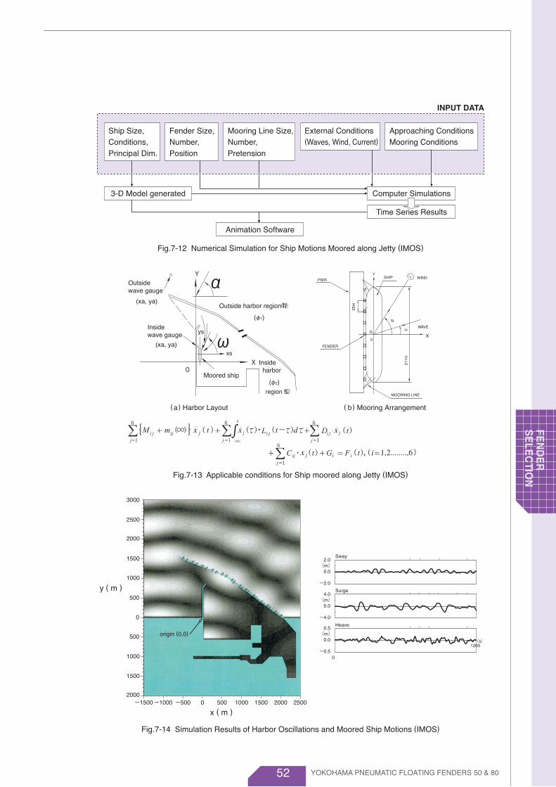
52
origin (0,0)
Fig.7-12 Numerical Simulation for Ship Motions Moored along Jetty (IMOS)
Fig.7-13 Applicable conditions for Ship moored along Jetty (IMOS)
Fig.7-14 Simulation Results of Harbor Oscillations and Moored Ship Motions (IMOS)
INPUT DATA
Mooring Line Size,Number, Pretension
Fender Size,Number, Position
Ship Size,Conditions,Principal Dim.
External Conditions(Waves, Wind, Current)
Approaching ConditionsMooring Conditions
3-D Model generated Computer Simulations
Time Series Results
Animation Software
SHIPPIER WIND
WAVE
X
Y
G
0
211m
25m
α
ε
FENDER
MOORING LINE
( b) Mooring Arrangement(a) Harbor Layout
Outsidewave gauge
Insidewave gauge
Outside harbor region ㈵(xa, ya)
(xa, ya)
Y
X
α
ω(φ1)
(φ2)
ys
xs
0Moored ship
Inside harbor
region ㈼
2.0(m)
0.0
-2.0
4.0(m)
0.0
-4.0
0.5(m)
0.0
-0.50
Sway
Surge
Heave
1200(s)
-1500
3000
2500
2000
1500
1000
0
500
500
1000
1500
2000-1000 -500 500 1000 1500 2000 25000
x ( m )
y ( m )
YOKOHAMA PNEUMATIC FLOATING FENDERS 50 & 80
FEN
DE
RS
ELE
CTIO
N

53
7.3 Required Data for Securing FendersIf assistance is required in selecting the proper fender for a particular application, select
the appropriate data sheet and submit the completed sheet together with your query.
1.
2.
3.
4.
5.
6.
7.
8.
9.
10.
11.
12.
13.
14.
15.
16.
17.
18.
19.
20.
21.
22.
23.
Location of site
Potential sea state
Potential beaufort scale
Type of lighteringe.g. ordinary lightering or reverse lightering
Water depth around STS ops.
Type of shipe.g. tanker, ore carrier, gas carrier, etc.
Role of lighteringe.g. discharging ship (STBL), receiving ship
Displacement tonnage (full loaded)
Displacement tonnage (at start of STS ops.)
Gross tonnage (GT)
Dead weight tonnage (DWT)
Length of ship (over-all length) (Loa)
Length of ship (length between P.P.) (Lpp)
Beam
Depth
Draft (full loaded)
Draft (at start of STS ops.)
Freeboard when coming in contact
Relative approaching velocity of ships
Mooring line sizes
Mooring line pretensions
Number of mooring lines
Other information
Fender Selection Data Form for Ship-to-Ship Use
7.3.1 Ship-to-Ship Use
m ( f t )
Ship-A
ton
ton
GT
DWT
m ( f t )
m ( f t )
m ( f t )
m ( f t )
m ( f t )
m ( f t )
m ( f t )
ton
ton
GT
DWT
m ( f t )
m ( f t )
m ( f t )
m ( f t )
m ( f t )
m ( f t )
m ( f t )
m/s ( f t /s)
mm
ton
Ship-B
YOKOHAMA PNEUMATIC FLOATING FENDERS 50 & 80
FEN
DE
R
SE
LEC
TIO
N

54
1.
2.
3.
4.
5.
6.
7.
8.
9.
10.
11.
12.
13.
14.
15.
16.
17.
18.
19.
20.
21.
22.
23.
24.
25.
26.
27.
28.
29.
30.
31.
32.
33.
34.
35.
36.
37.
38.
39.
40.
41.
42.
Location of site
Loading or unloading berth
Type of shipe.g. tanker, ore carrier, gas carrier, etc.
Displacement tonnage (full loaded)
Disp. tonnage when coming in contact
Gross tonnage (GT)
Dead weight tonnage (DWT)
Length of ship (over-all length) (Loa)
Length of ship (length between P.P.) (Lpp)
Beam
Depth
Draft (full loaded)
Draft when coming in contact
Freeboard when coming in contact
Berthing velocity to dock
Berthing angle
Required energy
Berthing point of ship from bow end
Kind of dockse.g. jetty or quay, dolphins, etc.
Top level from sea bed
Bottom elevation from sea level if bottom is elevated from sea bed
Length of jetty or quay
Width of dolphin
Height of dolphin
Number of dolphins
Spacing of dolphins
Permissible reaction force of dock
Permissible hull pressure
Permissible standoff of fender
Tidal range : HWL, High water level LWL, Low water level
Water depth around dock
Maximum wave height at mooring
Swell period
Long wave period
Maximum wind speed at mooring
Drawings: Attached or not
Required fender typeFloating fender, ABF-P, others
Required quantity of fenders
Mooring line sizes
Mooring line pretensions
Number of mooring lines
Other information
Fender Selection Data Form for Ship-to-Jetty Use
7.3.2 Ship-to-Jetty Use
ton
ton
GT
DWT
m ( f t )
m ( f t )
m ( f t )
m ( f t )
m ( f t )
m ( f t )
m ( f t )
m/s ( f t /s)
degree
kNm (f t -kips)
m ( f t )
m ( f t )
m ( f t )m ( f t )
m ( f t )
m ( f t )
Dolphins
m ( f t )
ton (kips)
ton /m2 (kips/ f t2)
m ( f t )
m ( f t )
m ( f t )m ( f t )
m ( f t )
m ( f t )
s
m/s
mm
ton
Small ship
ton
ton
GT
DWT
m ( f t )
m ( f t )
m ( f t )
m ( f t )
m ( f t )
m ( f t )
m ( f t )
m/s ( f t /s)
degree
kNm (f t -kips)
m ( f t )
Large ship
YOKOHAMA PNEUMATIC FLOATING FENDERS 50 & 80
FEN
DE
RS
ELE
CTIO
N
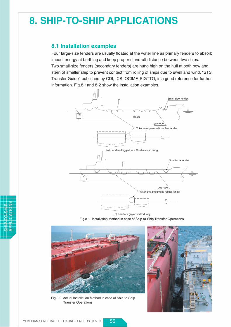
55
8. SHIP-TO-SHIP APPLICATIONS
8.1 Installation examplesFour large-size fenders are usually floated at the water line as primary fenders to absorb
impact energy at berthing and keep proper stand-off distance between two ships.
Two small-size fenders (secondary fenders) are hung high on the hull at both bow and
stern of smaller ship to prevent contact from rolling of ships due to swell and wind. "STS
Transfer Guide", published by CDI, ICS, OCIMF, SIGTTO, is a good reference for further
information. Fig.8-1and 8-2 show the installation examples.
Small size fender
tanker
Yokohama pneumatic rubber fender
guy rope
Small size fender
Yokohama pneumatic rubber fender
guy rope
Fig.8-1 Installation Method in case of Ship-to-Ship Transfer Operations
Fig.8-2 Actual Installation Method in case of Ship-to-Ship Transfer Operations
(a) Fenders Rigged in a Continuous String
(b) Fenders guyed individually
YOKOHAMA PNEUMATIC FLOATING FENDERS 50 & 80
SH
IP-T
O-S
HIP
A
PP
LIC
ATI
ON
S

56
8.2 EquipmentsAt both ends of the fender, first shackles need to be installed to connect a guy chain or
guy rope, Table 8-1 shows the recommended shackle size for each fender size. The first
shackle at each end is supplied together with the fenders.
Table 8-1 End Shackle for Chain / Wire Net Type & Sling Type
Size
Shackle Shackle
In Case of ChainNet & Wire Net
In Case of Sling Type
Initial InternalPressure
Double Ring
Towing Ring
SpecialTowing Ring
Type of Both Ends
of net Chain Net
& Wire Net mm ( inches)(kPa) mm ( inches)
50
80
50
80
50
80
50
80
50
80
50
80
50
80
50
80
50
80
50
80
50
80
50
80
50
80
50
80
50
80
50
80
50
80
22 (7/8)
22 (7/8)
22 (7/8)
22 (7/8)
22 (7/8)
22 (7/8)
22 (7/8)
22 (7/8)
22 (7/8)
22 (7/8)
25 (1)
25 (1)
25 (1)
25 (1)
SB16 (5/8)
SB16 (5/8)
SB16 (5/8)
SB16 (5/8)
SB16 (5/8)
SB16 (5/8)
SB16 (5/8)
SB16 (5/8)
SB16 (5/8)
SB16 (5/8)
SB16 (5/8)
SB16 (5/8)
SB18 (11/16)
SB18 (11/16)
SB18 (11/16)
SB20 (13 /16)
SB20 (13 /16)
SB20 (13 /16)
SB20 (13 /16)
SB24 (13 /16)
SB28 (1-1/8) × 2
SB30 (1-3/16) × 2
SB32 (1-1/4) × 2
SB36 (1-7/16)× 2
SB32 (1-1/4) × 2
SB34 (1-5/16) × 2
SB40 (1-9/16) × 2
SB44 (1-3/4) × 2
-
-
-
-
-
-
500 × 1000
600 × 1000
700 × 1500
1000 × 1500
1000 × 2000
1200 × 2000
1350 × 2500
1500 × 3000
1700 × 3000
2000 × 3500
2500 × 4000
2500 × 5500
3300 × 4500
3300 × 6500
3300 × 10600
4500 × 9000
4500 × 12000
SB24 (15/16)
SB24 (15/16)
SB24 (15/16)
SB24 (15/16)
SB26 (1)
SB28 (1-1/8)
SB32 (1-1/4)
SB34 (1-5/16)
SB34 (1-5/16)
SB40 (1-9/16)
SB36 (1-7/16)
SB40 (1-9/16)
SB44 (1-3 /4)
SB48 (1-7/ 8 )
-
-
-
-
-
-
YOKOHAMA PNEUMATIC FLOATING FENDERS 50 & 80
SH
IP-TO
-SH
IP
AP
PLIC
ATIO
NS

57
8.3 Installation Photographs
FPSO φ2500×5500LProduction Platform φ3300×4500L
FPSO φ3300×6500L
FPSO φ3300×6500L
YOKOHAMA PNEUMATIC FLOATING FENDERS 50 & 80
SH
IP-T
O-S
HIP
A
PP
LIC
ATI
ON
S

58 YOKOHAMA PNEUMATIC FLOATING FENDERS 50 & 80
9. SHIP-TO-JETTY APPLICATIONS
9.1 Installation MethodsAt both ends of the fender, first shackles, then swivel joints, followed by a further shackle
should be installed. A guy chain or guy rope is secured to the outer shackle. The swivel
joint prevents twisting of the guy chain or wire.
H.W.L.
L.W.L.
end link
end link
shackle
first shackle
shackle
anchor
swivel joint
towing ring
guy chain
rubber sleeve
FLOATING-TYPEYOKOHAMA PNEUMATICRUBBER FENDER
H.W.L
L.W.L
a) Dolphin
b) Continuous quay
Fig.9-1 Installation Methods for Ship-to-Jetty Applications
SH
IP-TO
-JETTY
A
PP
LICA
TION
S

59
9.2 Equipments
9.2.1 Typical installation
Typical installation equipment and necessary parts for installations are shown below.
The first shackles at each end of a fender are supplied with the fenders. Guy chains and
guy ropes, as well as shackles, swivel, rubber sleeves and anchors are not supplied with
the fenders, but they can be purchased separately upon request.
Fig.9-2 Equipments of Typical Installation for Ship-to-Jetty Applications.
YOKOHAMA PNEUMATIC FLOATING FENDERS 50 & 80
SH
IP-T
O-J
ETT
Y
AP
PLI
CA
TIO
NS
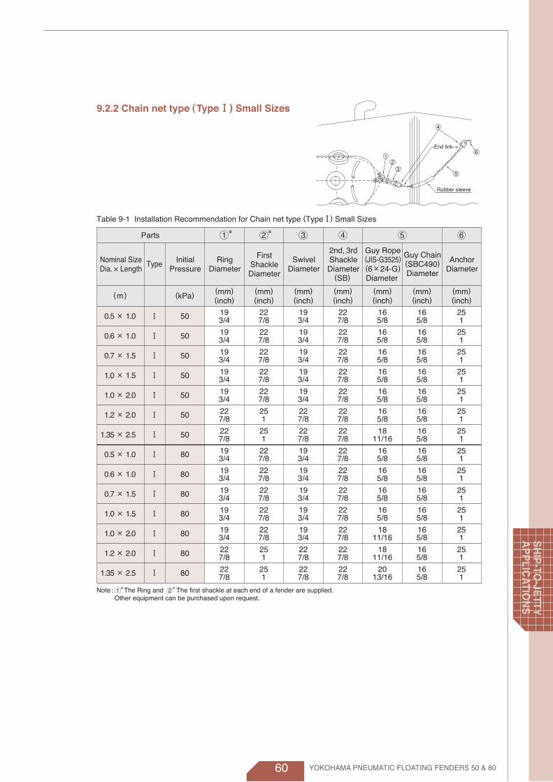
60 YOKOHAMA PNEUMATIC FLOATING FENDERS 50 & 80
9.2.2 Chain net type (Type Ⅰ) Small Sizes
End link
Rubber sleeve
21
3
4
5
6
Table 9-1 Installation Recommendation for Chain net type (TypeⅠ) Small Sizes
Parts
Guy Rope(JIS-G3525)(6×24-G)Diameter
2nd, 3rdShackleDiameter
(SB)
Guy Chain(SBC490)Diameter
AnchorDiameter
SwivelDiameter
FirstShackleDiameter
RingDiameter
InitialPressure
TypeNominal SizeDia. ×Length
(mm)(inch)
(mm)(inch)
(mm)(inch)
(mm)(inch)
(mm)(inch)
(mm)(inch)
(mm)(inch)
(kPa)(m)
0.5 × 1.0
0.6 × 1.0
0.7 × 1.5
1.0 × 1.5
1.0 × 2.0
1.2 × 2.0
1.35 × 2.5
0.5 × 1.0
0.6 × 1.0
0.7 × 1.5
1.0 × 1.5
1.0 × 2.0
1.2 × 2.0
1.35 × 2.5
Ⅰ
Ⅰ
Ⅰ
Ⅰ
Ⅰ
Ⅰ
Ⅰ
Ⅰ
Ⅰ
Ⅰ
Ⅰ
Ⅰ
Ⅰ
Ⅰ
50
50
50
50
50
50
50
80
80
80
80
80
80
80
19
19
19
19
19
22
22
19
19
19
19
19
22
22
3/4
3/4
3/4
3/4
3/4
7/8
7/8
3/4
3/4
3/4
3/4
3/4
7/8
7/8
22
22
22
22
22
25
25
22
22
22
22
22
25
25
7/8
7/8
7/8
7/8
7/8
1
1
7/8
7/8
7/8
7/8
7/8
1
1
19
19
19
19
19
22
22
19
19
19
19
19
22
22
3/4
3/4
3/4
3/4
3/4
7/8
7/8
3/4
3/4
3/4
3/4
3/4
7/8
7/8
22
22
22
22
22
22
22
22
22
22
22
22
22
22
7/8
7/8
7/8
7/8
7/8
7/8
7/8
7/8
7/8
7/8
7/8
7/8
7/8
7/8
16
16
16
16
16
16
18
16
16
16
16
18
18
20
5/8
5/8
5/8
5/8
5/8
5/8
11/16
5/8
5/8
5/8
5/8
11/16
11/16
13/16
16
16
16
16
16
16
16
16
16
16
16
16
16
16
5/8
5/8
5/8
5/8
5/8
5/8
5/8
5/8
5/8
5/8
5/8
5/8
5/8
5/8
25
25
25
25
25
25
25
25
25
25
25
25
25
25
1
1
1
1
1
1
1
1
1
1
1
1
1
1
1 2 3 4 5 6**
Note: The Ring and The first shackle at each end of a fender are supplied. Other equipment can be purchased upon request.
2*1*
SH
IP-TO
-JETTY
A
PP
LICA
TION
S
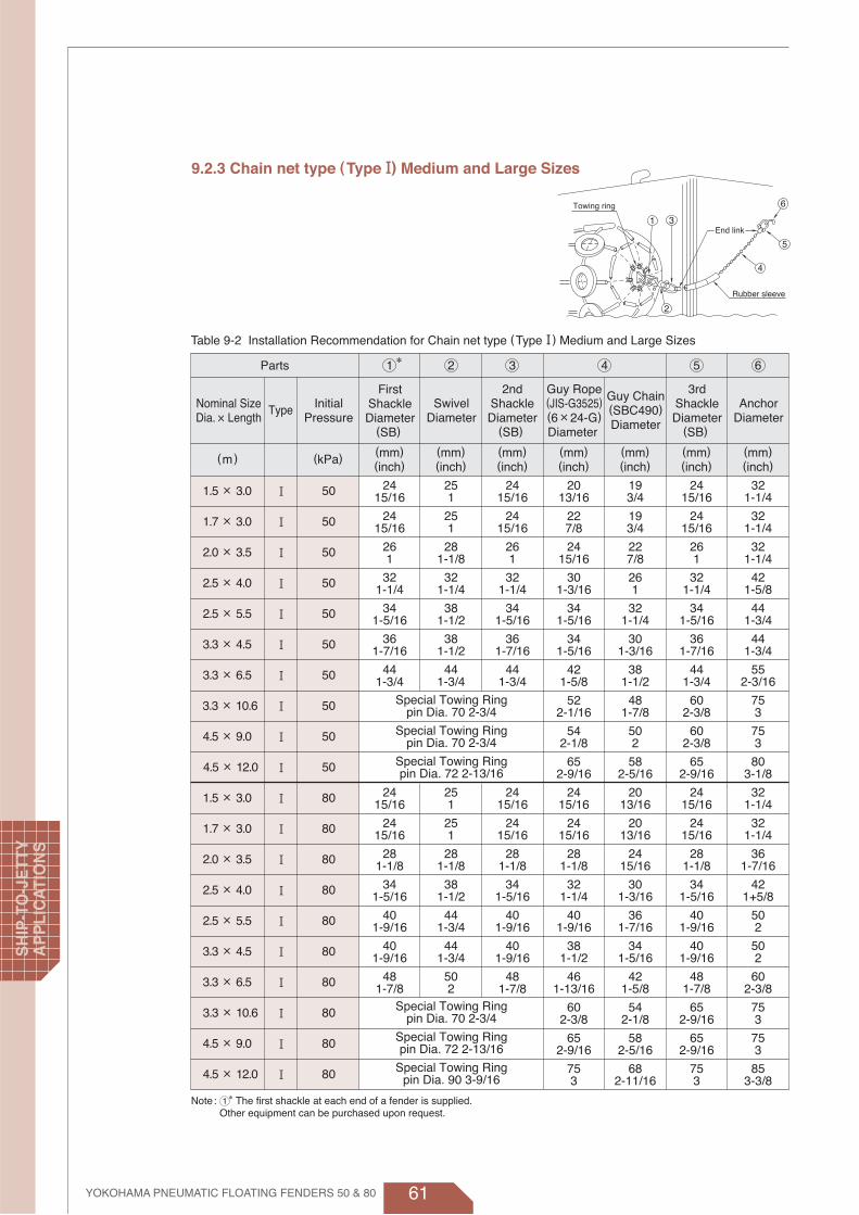
61
9.2.3 Chain net type (Type Ⅰ) Medium and Large Sizes
Table 9-2 Installation Recommendation for Chain net type (Type Ⅰ) Medium and Large Sizes
Parts
Guy Rope(JIS-G3525)(6×24-G)Diameter
2ndShackleDiameter
(SB)
3rdShackleDiameter
(SB)
Guy Chain(SBC490)Diameter
FirstShackleDiameter
(SB)
AnchorDiameter
SwivelDiameter
Special Towing Ringpin Dia. 70 2-3/4
Special Towing Ringpin Dia. 70 2-3/4
Special Towing Ringpin Dia. 72 2-13/16
Special Towing Ringpin Dia. 70 2-3/4
Special Towing Ringpin Dia. 72 2-13/16
Special Towing Ringpin Dia. 90 3-9/16
(mm)(inch)
(mm)(inch)
(kPa)(m)
1.5 × 3.0
1.7 × 3.0
2.0 × 3.5
2.5 × 4.0
2.5 × 5.5
3.3 × 4.5
3.3 × 6.5
3.3 × 10.6
4.5 × 9.0
4.5 × 12.0
1.5 × 3.0
1.7 × 3.0
2.0 × 3.5
2.5 × 4.0
2.5 × 5.5
3.3 × 4.5
3.3 × 6.5
3.3 × 10.6
4.5 × 9.0
4.5 × 12.0
Ⅰ
Ⅰ
Ⅰ
Ⅰ
Ⅰ
Ⅰ
Ⅰ
Ⅰ
Ⅰ
Ⅰ
Ⅰ
Ⅰ
Ⅰ
Ⅰ
Ⅰ
Ⅰ
Ⅰ
Ⅰ
Ⅰ
Ⅰ
50
50
50
50
50
50
50
50
50
50
80
80
80
80
80
80
80
80
80
80
24
24
26
32
34
36
44
24
24
28
34
40
40
48
15/16
15/16
1
1-1/4
1-5/16
1-7/16
1-3/4
15/16
15/16
1-1/8
1-5/16
1-9/16
1-9/16
1-7/8
25
25
28
32
38
38
44
25
25
28
38
44
44
50
1
1
1-1/8
1-1/4
1-1/2
1-1/2
1-3/4
1
1
1-1/8
1-1/2
1-3/4
1-3/4
2
24
24
26
32
34
36
44
24
24
28
34
40
40
48
15/16
15/16
1
1-1/4
1-5/16
1-7/16
1-3/4
15/16
15/16
1-1/8
1-5/16
1-9/16
1-9/16
1-7/8
20
22
24
30
34
34
42
52
54
65
24
24
28
32
40
38
46
60
65
75
13/16
7/8
15/16
1-3/16
1-5/16
1-5/16
1-5/8
2-1/16
2-1/8
2-9/16
15/16
15/16
1-1/8
1-1/4
1-9/16
1-1/2
1-13/16
2-3/8
2-9/16
3
19
19
22
26
32
30
38
48
50
58
20
20
24
30
36
34
42
54
58
68
3/4
3/4
7/8
1
1-1/4
1-3/16
1-1/2
1-7/8
2
2-5/16
13/16
13/16
15/16
1-3/16
1-7/16
1-5/16
1-5/8
2-1/8
2-5/16
2-11/16
24
24
26
32
34
36
44
60
60
65
24
24
28
34
40
40
48
65
65
75
15/16
15/16
1
1-1/4
1-5/16
1-7/16
1-3/4
2-3/8
2-3/8
2-9/16
15/16
15/16
1-1/8
1-5/16
1-9/16
1-9/16
1-7/8
2-9/16
2-9/16
3
32
32
32
42
44
44
55
75
75
80
32
32
36
42
50
50
60
75
75
85
1-1/4
1-1/4
1-1/4
1-5/8
1-3/4
1-3/4
2-3/16
3
3
3-1/8
1-1/4
1-1/4
1-7/16
1+5/8
2
2
2-3/8
3
3
3-3/8
(mm)(inch)
(mm)(inch)
(mm)(inch)
(mm)(inch)
(mm)(inch)
InitialPressure
TypeNominal SizeDia. ×Length
Rubber sleeve
End link
Towing ring
1
6
2
3
4
5
1 2 3 4 5 6
Note: The first shackle at each end of a fender is supplied. Other equipment can be purchased upon request.
1*
*
YOKOHAMA PNEUMATIC FLOATING FENDERS 50 & 80
SH
IP-T
O-J
ETT
Y
AP
PLI
CA
TIO
NS

62 YOKOHAMA PNEUMATIC FLOATING FENDERS 50 & 80
9.2.4 Sling type (TypeⅡ)
Table 9-3 Installation Recommendation for Sling type (TypeⅡ)
Parts
Guy Chain(SBC490)Diameter
Guy Rope(JIS-G3525)(6×24-G)Diameter
2ndShackleDiameter
(SB)
3rdShackleDiameter
(SB)
AnchorDiameter
SwivelDiameter
Special Towing Ringpin Dia. 70 2-3/4
Special Towing Ringpin Dia. 70 2-3/4
FirstShackleDiameter
(SB)
InitialPressure
TypeNominal SizeDia. ×Length
(mm)(inch)
(mm)(inch)
(mm)(inch)
(mm)(inch)
(mm)(inch)
(mm)(inch)
(mm)(inch)
(kPa)(m)
0.5 × 1.0
0.6 × 1.0
0.7 × 1.5
1.0 × 1.5
1.0 × 2.0
1.2 × 2.0
1.35 × 2.5
1.5 × 3.0
1.7 × 3.0
2.0 × 3.5
2.5 × 4.0
2.5 × 5.5
3.3 × 4.5
3.3 × 6.5
3.3 × 10.6
0.5 × 1.0
0.6 × 1.0
0.7 × 1.5
1.0 × 1.5
1.0 × 2.0
1.2 × 2.0
1.35 × 2.5
1.5 × 3.0
1.7 × 3.0
2.0 × 3.5
2.5 × 4.0
2.5 × 5.5
3.3 × 4.5
3.3 × 6.5
3.3 × 10.6
ⅡⅡⅡⅡⅡⅡⅡⅡⅡⅡⅡⅡⅡⅡⅡⅡⅡⅡⅡⅡⅡⅡⅡⅡⅡⅡⅡⅡⅡⅡ
50
50
50
50
50
50
50
50
50
50
50
50
50
50
50
80
80
80
80
80
80
80
80
80
80
80
80
80
80
80
16
16
16
16
16
16
18
18
20
20
28×2
32×2
36+32
40×2
16
16
16
16
16
16
18
20
20
22
30×2
36×2
36+34
44×2
5/8
5/8
5/8
5/8
5/8
5/8
11/16
11/16
13/16
13/16
1-1/8
1-1/4
1-7/16+1-1/4
1-9/16
5/8
5/8
5/8
5/8
5/8
5/8
11/16
13/16
13/16
7/8
1-3/16
1-7/16
1-7/16+1-5/16
1-3/4
16
16
16
19
19
19
19
22
25
28
32
38
38
44
16
16
16
19
19
19
19
25
25
28
38
44
44
50
5/8
5/8
5/8
3/4
3/4
3/4
3/4
7/8
1
1-1/8
1-1/4
1-1/2
1-1/2
1-3/4
5/8
5/8
5/8
3/4
3/4
3/4
3/4
1
1
1-1/8
1-1/2
1-3/4
1-3/4
2
22
22
22
22
22
22
22
24
24
26
32
34
36
44
22
22
22
22
22
22
22
24
24
28
34
40
40
48
7/8
7/8
7/8
7/8
7/8
7/8
7/8
15/16
15/16
1
1-1/4
1-5/16
1-7/16
1-3/4
7/8
7/8
7/8
7/8
7/8
7/8
7/8
15/16
15/16
1-1/8
1-5/16
1-9/16
1-9/16
1-7/8
16
16
16
16
16
16
18
20
22
24
30
34
34
42
52
16
16
16
16
18
18
20
24
24
28
32
40
38
46
60
5/8
5/8
5/8
5/8
5/8
5/8
11/16
13/16
7/8
15/16
1-3/16
1-5/16
1-5/16
1-5/8
2-1/16
5/8
5/8
5/8
5/8
11/16
11/16
13/16
15/16
15/16
1-1/8
1-1/4
1-9/16
1-1/2
1-13/16
2-3/8
16
16
16
16
16
16
16
19
19
22
26
32
30
38
48
16
16
16
16
16
16
16
20
20
24
30
36
34
42
54
5/8
5/8
5/8
5/8
5/8
5/8
5/8
3/4
3/4
7/8
1
1-1/4
1-3/16
1-1/2
1-7/8
5/8
5/8
5/8
5/8
5/8
5/8
5/8
13/16
13/16
15/16
1-3/16
1-7/16
1-5/16
1-5/8
2-1/8
22
22
22
22
22
22
22
24
24
26
32
34
36
44
60
22
22
22
22
22
22
22
24
24
28
34
40
40
48
65
7/8
7/8
7/8
7/8
7/8
7/8
7/8
15/16
15/16
1
1-1/4
1-5/16
1-7/16
1-3/4
2-3/8
7/8
7/8
7/8
7/8
7/8
7/8
7/8
15/16
15/16
1-1/8
1-5/16
1-9/16
1-9/16
1-7/8
2-9/16
25
25
25
25
25
25
25
32
32
32
42
44
44
55
75
25
25
25
25
25
25
25
32
32
36
42
50
50
60
75
1
1
1
1
1
1
1
1-1/4
1-1/4
1-1/4
1-5/8
1-3/4
1-3/4
2-3/16
3
1
1
1
1
1
1
1
1-1/4
1-1/4
1-7/16
1-5/8
2
2
2-3/8
3
Rubber sleeve
End link
1
5
2
3
4
6
1 2 3 4 5 6
Note: The first shackle at each end of a fender is supplied. Other equipment can be purchased upon request.
1*
SH
IP-TO
-JETTY
A
PP
LICA
TION
S

63
Table 9-4 Dimension of jetty for installation
Initial Pressure
(kPa)
A(mm)
B(mm)
C(mm)
D(mm)
E(mm)
500 × 1000
600 × 1000
700 × 1500
1000 × 1500
1000 × 2000
1200 × 2000
1350 × 2500
1500 × 3000
1700 × 3000
2000 × 3500
2500 × 4000
2500 × 5500
3300 × 4500
3300 × 6500
3300 × 10600
4500 × 9000
4500 × 12000
500 × 1000
600 × 1000
700 × 1500
1000 × 1500
1000 × 2000
1200 × 2000
1350 × 2500
1500 × 3000
1700 × 3000
2000 × 3500
2500 × 4000
2500 × 5500
3300 × 4500
3300 × 6500
3300 × 10600
4500 × 9000
4500 × 12000
50
50
50
50
50
50
50
50
50
50
50
50
50
50
50
50
50
80
80
80
80
80
80
80
80
80
80
80
80
80
80
80
80
80
420
530
530
840
890
1060
1250
1410
1620
1920
2440
2460
3300
3360
3400
4660
4710
410
520
530
840
890
1060
1250
1400
1610
1910
2420
2450
3270
3330
3370
4640
4690
320
410
390
640
690
820
980
1110
1280
1520
1940
1960
2640
2700
2740
3760
3810
310
400
390
640
690
820
980
1100
1270
1510
1920
1950
2610
2670
2710
3740
3790
160
150
270
300
250
320
290
310
320
360
420
400
480
420
380
480
430
170
160
270
300
250
320
290
320
330
370
440
410
510
450
410
500
450
170
170
290
330
280
350
330
350
370
420
490
470
570
510
470
610
560
180
180
290
330
280
350
330
360
380
430
510
480
600
540
500
630
580
1300
1300
1950
1950
2600
2600
3250
3900
3900
4550
5200
7150
5850
8450
13780
11700
15600
1300
1300
1950
1950
2600
2600
3250
3900
3900
4550
5200
7150
5850
8450
13780
11700
15600
Size
E
D
C
A B
JETTY/QUAYOR DOLPHIN
L.W.L
H.W.L
tidal
rang
e
state at 60% def.
9.3 Dimension of Jetty for InstallationRubber fender should be in a
state of plane contact, as shown
below, even when it is deflected.
Note : Above figures are obtained using weights of chain net type, and the difference between the figures for wire net type is small, therefore, the above figures may be used also for wire net type as well.
YOKOHAMA PNEUMATIC FLOATING FENDERS 50 & 80
SH
IP-T
O-J
ETT
Y
AP
PLI
CA
TIO
NS
*

64
9.4 Installation Photographs
YOKOHAMA PNEUMATIC FLOATING FENDERS 50 & 80
LNG Terminal φ3300×6500L
Coal Terminal φ4500×9000L
Ship yard φ3300×6500L High Speed Ferry φ2000×3500L
IRONSTONE TERMINAL φ3300×10600L
LNG Terminal φ3300×4500L
SH
IP-TO
-JETTY
A
PP
LICA
TION
S

65YOKOHAMA PNEUMATIC FLOATING FENDERS 50 & 80
Ferry Terminal φ1000×2000L φ700×1500L
Terminal:Pneumatic Cell ABF-P
Terminal φ3300×4500L
LNG Terminal:Pneumatic Cell ABF-P
SH
IP-T
O-J
ETT
Y
AP
PLI
CA
TIO
NS

66 YOKOHAMA PNEUMATIC FLOATING FENDERS 50 & 80
10. MAINTENANCE TOOLS
The following maintenance tools can be purchased upon request.
10.1 Small and medium-size (Size:φ500mm~φ2000mm).
Remarks: Adhesive (cement) is not included in repair kits because of short life time and
transportation problems, and therefore TIP TOP SC 2000 or SC4000 needs to be
purchased locally.
A. Repair Tool Kit1) Rubber sheet2) Rubber plugs 3) Brush4) Sandpaper5) Tool for inserting rubber plug6) Hand roller
0.510
1111
m2
pcs.pc.sheetpc.pc.
Repair Tool Kit for Small and Medium size Fenders
B. Installation Tool Kit1) Air pressure gauge with air chuck2) Air filling hose with air chuck3) Box spanner for removing air valve4) Valve core screw driver5) Spare valve (air valve)
C. Manuals
D. Fender logbook
110
111
setmpc.pc.pc.
Installation Tool Kit for Small and Medium size Fenders
RE
PAIR
KITS
AN
D
SPA
RE
PAR
TS

67YOKOHAMA PNEUMATIC FLOATING FENDERS 50 & 80
Remarks: Adhesive (cement) is not included in repair kits because of short life time and
transportation problems, and therefore TIP TOP SC 2000 or SC4000 needs to be
purchased locally.
10.2 Large-size (Size:φ2500mm~φ4500mm).
A. Repair Tool Kit1) Rubber sheet 2) Brush3) Sandpaper4) Wire brush5) Hand roller
12211
m2(0.5m2×2)pcs.sheetspc.pc.
Repair Tool Kit for Large size Fenders
B. Installation Tool Kit1) Air pressure gauge with air chuck2) Air filling hose with air chuck3) Box spanner for removing air valve4) Valve core screw driver5) Spare valve (air valve)
C. Manuals
D. Fender logbook
E. Safety valve logbook
120
111
setmpc.pc.pc.
Installation Tool Kit for Large size Fenders
RE
PAIR
KIT
S A
ND
S
PAR
E P
AR
TS

68 YOKOHAMA PNEUMATIC FLOATING FENDERS 50 & 80
11. PRECAUTIONS ON HANDLING
(1) Because the pneumatic rubber fender is usually shipped in deflated condition (as
shown in the pictures below), it should be immediately inflated to the pressure 20~ 30kPa upon arrival at its destination.
(2) When storing the fender more than three months without use, reduce internal pressure
to about half of initial pressure (20~30kPa) so that the pressure will not rise too high
due to a rise in the atmospheric temperature. Do not deflate or fold.
(3) For further instructions about handling, please refer to the handling and maintenance
manual that is provided with each fender purchase, or please contact The Yokohama
Rubber Co., Ltd for assistance.
Fig.11-1 φ4500×9000L-P80 Transportation on Steel Pallet
Fig.11-2 φ3300×6500L-P80 Transportation by Open- top Container
Fig.11-3 φ2500×5500L-P50 Transportation by Open- top Container
Fig.11-4 φ3300×6500L-P50 Body Only under the deflated condition P
RE
CA
UTIO
NS
ON
H
AN
DLIN
G
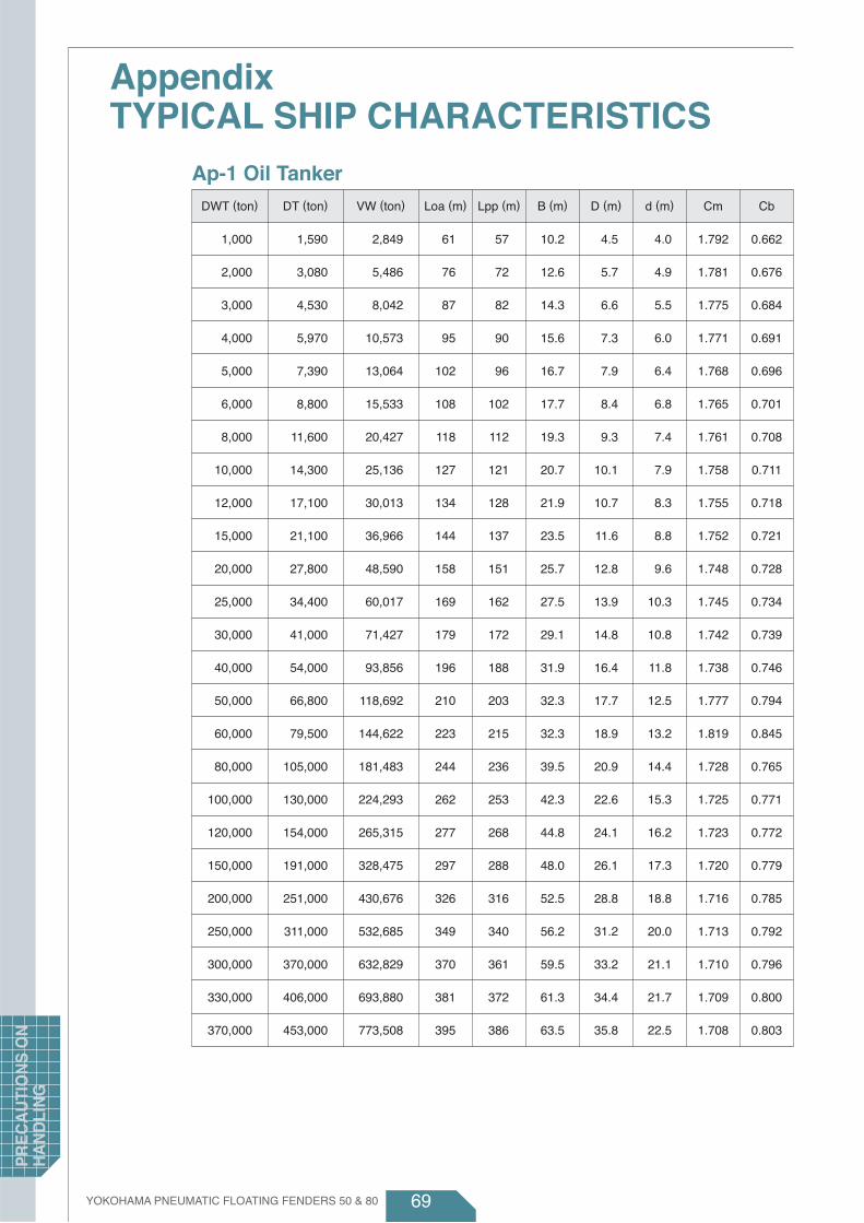
69
Appendix TYPICAL SHIP CHARACTERISTICS
Ap-1 Oil TankerDWT (ton) VW (ton) Loa (m) Lpp (m) B (m) D (m) d (m) Cm CbDT (ton)
1,000
2,000
3,000
4,000
5,000
6,000
8,000
10,000
12,000
15,000
20,000
25,000
30,000
40,000
50,000
60,000
80,000
100,000
120,000
150,000
200,000
250,000
300,000
330,000
370,000
2,849
5,486
8,042
10,573
13,064
15,533
20,427
25,136
30,013
36,966
48,590
60,017
71,427
93,856
118,692
144,622
181,483
224,293
265,315
328,475
430,676
532,685
632,829
693,880
773,508
61
76
87
95
102
108
118
127
134
144
158
169
179
196
210
223
244
262
277
297
326
349
370
381
395
57
72
82
90
96
102
112
121
128
137
151
162
172
188
203
215
236
253
268
288
316
340
361
372
386
10.2
12.6
14.3
15.6
16.7
17.7
19.3
20.7
21.9
23.5
25.7
27.5
29.1
31.9
32.3
32.3
39.5
42.3
44.8
48.0
52.5
56.2
59.5
61.3
63.5
4.5
5.7
6.6
7.3
7.9
8.4
9.3
10.1
10.7
11.6
12.8
13.9
14.8
16.4
17.7
18.9
20.9
22.6
24.1
26.1
28.8
31.2
33.2
34.4
35.8
4.0
4.9
5.5
6.0
6.4
6.8
7.4
7.9
8.3
8.8
9.6
10.3
10.8
11.8
12.5
13.2
14.4
15.3
16.2
17.3
18.8
20.0
21.1
21.7
22.5
1.792
1.781
1.775
1.771
1.768
1.765
1.761
1.758
1.755
1.752
1.748
1.745
1.742
1.738
1.777
1.819
1.728
1.725
1.723
1.720
1.716
1.713
1.710
1.709
1.708
0.662
0.676
0.684
0.691
0.696
0.701
0.708
0.711
0.718
0.721
0.728
0.734
0.739
0.746
0.794
0.845
0.765
0.771
0.772
0.779
0.785
0.792
0.796
0.800
0.803
1,590
3,080
4,530
5,970
7,390
8,800
11,600
14,300
17,100
21,100
27,800
34,400
41,000
54,000
66,800
79,500
105,000
130,000
154,000
191,000
251,000
311,000
370,000
406,000
453,000
YOKOHAMA PNEUMATIC FLOATING FENDERS 50 & 80
PR
EC
AU
TIO
NS
ON
H
AN
DLI
NG
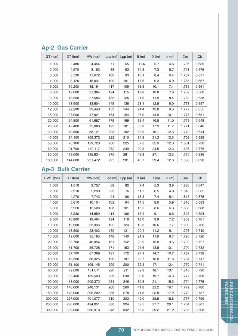
70
Ap-2 Gas CarrierGT (ton) VW (ton) Loa (m) Lpp (m) B (m) D (m) d (m) Cm CbDT (ton)
1,000
2,000
3,000
4,000
5,000
6,000
8,000
10,000
12,000
15,000
20,000
25,000
30,000
40,000
50,000
60,000
80,000
100,000
4,454
8,183
11,672
15,031
18,191
21,384
27,586
33,604
39,440
47,921
61,687
75,086
88,121
109,372
129,723
149,117
185,834
221,472
71
88
100
109
117
124
135
145
153
164
179
192
203
222
238
252
275
295
65
82
93
101
109
115
126
136
144
154
169
181
192
210
225
239
261
281
111.6
14.3
16.1
17.6
18.8
19.8
21.6
23.1
24.4
26.0
28.4
30.3
32.0
34.8
37.2
39.3
42.8
45.7
5.7
7.3
8.4
9.3
10.1
10.8
11.9
12.9
13.8
14.9
16.5
17.9
19.1
21.2
22.9
24.5
27.1
29.4
4.6
5.7
6.4
6.9
7.4
7.8
8.4
9.0
9.5
10.1
11.0
11.7
12.3
12.3
12.3
12.3
12.3
12.3
1.796
1.791
1.787
1.785
1.783
1.782
1.780
1.778
1.777
1.775
1.773
1.771
1.770
1.706
1.661
1.626
1.575
1.538
0.685
0.676
0.671
0.667
0.661
0.660
0.658
0.657
0.655
0.651
0.648
0.646
0.644
0.695
0.738
0.775
0.836
0.890
2,480
4,570
6,530
8,420
10,200
12,000
15,500
18,900
22,200
27,000
34,800
42,400
49,800
64,100
78,100
91,700
118,000
144,000
Ap-3 Bulk CarrierDWT (ton) VW (ton) Loa (m) Lpp (m) B (m) D (m) d (m) Cm CbDT (ton)
1,000
2,000
3,000
4,000
5,000
6,000
8,000
10,000
12,000
15,000
20,000
25,000
30,000
40,000
50,000
60,000
80,000
100,000
120,000
150,000
200,000
250,000
300,000
2,757
5,290
7,743
10,154
12,508
14,859
19,464
23,936
28,403
35,185
46,054
56,728
67,389
88,325
108,145
131,611
169,503
209,372
248,131
306,202
401,077
494,051
586,918
68
83
94
102
108
114
124
132
139
148
161
171
181
196
209
220
239
254
268
286
310
330
348
62
76
86
94
101
106
116
124
131
140
152
163
172
187
200
211
230
246
260
278
303
324
342
9.4
11.7
13.3
14.5
15.5
16.4
18.0
19.3
20.4
21.9
23.9
25.6
27.1
29.7
32.3
32.3
36.8
39.5
41.8
44.8
49.0
52.5
55.5
5.3
6.5
7.4
8.0
8.6
9.1
9.9
10.6
11.2
11.9
13.0
13.9
14.7
16.0
17.1
18.1
19.7
21.1
22.2
23.8
25.9
27.7
29.2
3.9
4.8
5.4
5.9
6.3
6.6
7.2
7.7
8.1
8.7
9.5
10.1
10.7
11.6
12.4
13.1
14.3
15.3
16.1
17.2
18.8
20.1
21.2
1.826
1.818
1.813
1.810
1.808
1.805
1.802
1.800
1.798
1.795
1.792
1.790
1.787
1.784
1.770
1.813
1.777
1.774
1.772
1.770
1.767
1.764
1.763
0.647
0.665
0.675
0.683
0.688
0.694
0.701
0.706
0.710
0.720
0.727
0.732
0.738
0.747
0.741
0.790
0.768
0.775
0.780
0.787
0.796
0.801
0.808
1,510
2,910
4,270
5,610
6,920
8,230
10,800
13,300
15,800
19,600
25,700
31,700
37,700
49,500
61,100
72,600
95,400
118,000
140,000
173,000
227,000
280,000
333,000
YOKOHAMA PNEUMATIC FLOATING FENDERS 50 & 80
PR
EC
AU
TION
S O
N
HA
ND
LING

71
Appendix TYPICAL SHIP CHARACTERISTICS
Ap-4 General Cargo ShipDWT (ton) VW (ton) Loa (m) Lpp (m) B (m) D (m) d (m) Cm CbDT (ton)
1,000
2,000
3,000
4,000
5,000
6,000
8,000
10,000
12,000
15,000
20,000
25,000
30,000
40,000
50,000
2,908
5,672
8,395
11,065
13,714
16,356
21,558
26,715
31,894
39,514
52,221
64,629
77,090
101,768
126,208
67
84
95
104
111
118
129
138
146
156
171
183
194
212
227
62
78
88
97
104
110
121
130
137
147
162
173
184
201
216
10.8
13.1
14.7
15.9
17.0
17.8
19.3
20.6
21.6
23.0
24.9
26.5
27.9
30.2
32.2
5.8
7.2
8.1
8.8
9.5
10.0
10.9
11.6
12.3
13.2
14.4
15.3
16.2
17.7
18.9
3.9
4.9
5.6
6.1
6.6
7.0
7.7
8.3
8.8
9.4
10.4
11.2
11.8
13.0
14.0
1.721
1.745
1.760
1.770
1.779
1.786
1.797
1.805
1.812
1.821
1.832
1.841
1.849
1.860
1.870
0.625
0.634
0.641
0.644
0.647
0.649
0.653
0.655
0.659
0.661
0.666
0.668
0.670
0.674
0.678
1,690
3,250
4,770
6,250
7,710
9,160
12,000
14,800
17,600
21,700
28,500
35,100
41,700
54,700
67,500
Ap-5 Container ShipDWT (ton) VW (ton) Loa (m) Lpp (m) B (m) D (m) d (m) Cm CbDT (ton)
7,000
8,000
10,000
12,000
15,000
20,000
25,000
30,000
40,000
50,000
60,000
80,000
100,000
18,273
20,699
25,734
30,782
38,115
50,376
62,504
74,489
98,838
126,047
145,611
186,920
227,756
122
129
141
151
165
185
202
217
243
266
285
320
349
114
121
132
142
155
174
191
205
230
252
271
304
332
20.3
21.1
22.4
23.5
25.0
27.1
28.7
30.2
32.3
32.3
36.5
39.4
41.9
9.8
10.4
11.3
12.2
13.3
14.9
16.3
17.5
19.6
21.4
23.0
25.8
28.2
7.2
7.5
8.0
8.5
9.1
9.9
10.6
11.2
12.2
13.1
13.8
14.1
14.4
1.708
1.711
1.716
1.720
1.725
1.731
1.736
1.740
1.756
1.808
1.756
1.715
1.687
0.624
0.619
0.617
0.617
0.612
0.609
0.606
0.603
0.606
0.641
0.594
0.629
0.657
10,700
12,100
15,000
17,900
22,100
29,100
36,000
42,800
56,300
69,700
82,900
109,000
135,000
YOKOHAMA PNEUMATIC FLOATING FENDERS 50 & 80
PR
EC
AU
TIO
NS
ON
H
AN
DLI
NG

72
Ap-6 Passenger ShipGT (ton) VW (ton) Loa (m) Lpp (m) B (m) D (m) d (m) Cm CbDT (ton)
1,000
2,000
3,000
4,000
5,000
6,000
8,000
10,000
12,000
15,000
20,000
25,000
30,000
40,000
50,000
60,000
80,000
1,468
2,807
4,120
5,394
6,654
7,895
10,360
12,795
15,207
18,737
24,676
29,492
34,086
42,826
51,283
59,341
74,952
64
81
93
103
111
119
131
142
151
163
180
194
207
229
247
263
291
60
75
86
95
102
108
119
128
136
146
161
173
184
202
218
231
254
12.1
14.4
15.9
17.1
18.1
19.0
20.4
21.5
22.5
23.8
25.6
27.1
28.3
30.5
32.2
33.7
36.2
4.9
6.3
7.4
8.3
9.0
9.7
10.8
11.7
12.6
13.7
15.3
16.7
17.9
19.9
21.7
23.3
26.0
2.6
3.4
4.0
4.4
4.9
5.2
5.8
6.4
6.9
7.5
8.4
8.4
8.4
8.4
8.4
8.4
8.4
1.425
1.470
1.498
1.520
1.537
1.551
1.574
1.593
1.609
1.629
1.656
1.620
1.593
1.552
1.522
1.498
1.464
0.539
0.509
0.493
0.481
0.472
0.464
0.454
0.445
0.439
0.429
0.420
0.451
0.477
0.521
0.559
0.591
0.646
1,030
1,910
2,750
3,550
4,330
5,090
6,580
8,030
9,450
11,500
14,900
18,200
21,400
27,600
33,700
39,600
51,200
Ap-7 FerryGT (ton) VW (ton) Loa (m) Lpp (m) B (m) D (m) d (m) Cm CbDT (ton)
1,000
2,000
3,000
4,000
5,000
6,000
8,000
10,000
12,000
15,000
20,000
25,000
30,000
40,000
1,838
3,653
5,469
7,278
9,094
10,901
14,529
18,109
21,701
27,184
36,153
45,159
54,194
72,336
67
86
99
110
119
127
141
153
164
177
197
213
228
253
61
78
91
101
110
117
131
142
152
165
183
199
213
236
14.3
17.0
18.8
20.2
21.3
22.3
24.0
25.4
26.5
28.0
30.1
31.9
33.3
35.8
5.5
6.8
7.7
8.4
9.0
9.5
10.4
11.1
11.8
12.6
13.8
14.7
15.6
17.1
3.4
4.2
4.8
5.2
5.5
5.8
6.3
6.8
7.2
7.6
8.3
8.9
9.4
10.2
1.482
1.497
1.506
1.513
1.518
1.523
1.529
1.535
1.539
1.545
1.552
1.557
1.562
1.569
0.405
0.424
0.436
0.444
0.451
0.457
0.466
0.472
0.478
0.487
0.496
0.503
0.510
0.521
1,240
2,440
3,630
4,810
5,990
7,160
9,500
11,800
14,100
17,600
23,300
29,000
34,700
46,100
YOKOHAMA PNEUMATIC FLOATING FENDERS 50 & 80
PR
EC
AU
TION
S O
N
HA
ND
LING

Website: www.yrc.co.jp/english/mb/industrial / index.htmlC 2008 THE YOKOHAMA RUBBER CO.,LTD. 2015 04 TSP DTT YRC AD Catalog No. AF/CAT/2015/04
YOKOHAMA INDUSTRIAL PRODUCTS SALES SHANGHAI, CO.,LTD.Sales Subsidiary
YOKOHAMA INDUSTRIAL PRODUCTS EUROPE GmbHSales Subsidiary
Monschauer Str. 12 40549 Dusseldolf, GermanyPhone:+49-211-5374-0570 Fax:+49-211-5374-0579
YOKOHAMA INDUSTRIES AMERICAS INC.Sales Subsidiary
105, Kuhlman Blvd., Versailles, KY 40383, U.S.A.Phone:+1-859-879-2858 Fax:+1-859-873-8943
YOKOHAMA INDUSTRIAL PRODUCTS SALES SHANGHAI, CO.,LTD.Sales Subsidiary
3209-10, 32F, New Town Center NO.83 Loushanguan rd, Changning district, Shanghai, ChinaPhone:+86-21-6236-8811 Fax:+86-21-5206-7165
YOKOHAMA INDUSTRIAL PRODUCTS ASIA-PACIFIC PTE. LTD.Sales and Technical Services
1 Tampines Central 5, CPF Tampines Building ♯07-10, Singapore 529508Phone:+65-6587-7190 Fax:+65-6260-4394
THE YOKOHAMA RUBBER CO.,LTD.Head office / Industrial Products Global Sales and Planning Dept.
36-11 Shimbashi 5-chome, Minato-ku, Tokyo 105-8685 JapanPhone:+81-3-5400-4816 Fax:+81-3-5400-4830e-mail : [email protected]
Manufacture Plant / Engineering Department2-1 Oiwake, Hiratsuka, kanagawa 254-8601 Japan
PT. YOKOHAMA INDUSTRIAL PRODUCTS MANUFACTURING INDONESIAManufacturing Plant
Jl. Mas Surya Negara VIII No.6 Kawasan Industri Terpadu Kabil Batam 29467, IndonesiaPhone:+62-778-807-0100 Fax,Phone:+62-778-807-0101
YOKOHAMA INDUSTRIES AMERICAS INC.Sales Subsidiary
YOKOHAMA INDUSTRIAL PRODUCTS ASIA-PACIFIC PTE. LTD.Sales and Technical Services
THE YOKOHAMA RUBBER CO.,LTD.Head office / Industrial Products Global Sales and Planning Dept.
YOKOHAMA INDUSTRIAL PRODUCTS EUROPE GmbHSales Subsidiary
PT. YOKOHAMA INDUSTRIAL PRODUCTS MANUFACTURING INDONESIAManufacturing Plant


