Aerospace Education & Research in the Area of Design
Diamond Jubilee Lectures 2003-04Department of Aerospace EngineeringIndian Institute of Science, Bangalore
K. SudhakarCentre for Aerospace Systems Design &
EngineeringIndian Institute of Technology
Mumbai 400 076October 30, 2003

Year 1997
“Technology Perspective – The Next Decade”Aeronautics Research & Development BoardAR&DB/TC/001, May 1997
Suggested centres of excellence to be supported by AR&DB are;
– CFD – Advanced Composites – Systems Design & Engineering ? ?

Years 1990 -1997
• Aerospace Design as a discipline at IITB
– Specialization dropped
– Courses had tapered off
– Design, Build Or Open ended problems shunned
– No research interest among faculty
• March 1998 : AR&DB Sanction arrives

CASDE : July 1998
Mission
CASDE shall strive to develop and retain strong links with
Indian Aerospace Industry and shall engage in
R&D activities with worldwide visibility
http://www.casde.iitb.ac.in/

Objectives of CASDE
• M. Tech Programme in Systems Design & Engineering
• Modeling & Simulation Laboratory
• System Design Methodologies
• Awareness Creation

M. Tech in Systems Design & Engineering
• What do others teach?
• What can draw / retain student interest?
• What will faculty want to teach?
• What will industry want?
What all should be taught?
Form a composite team •
Brain-storming session •
http://www.casde.iitb.ac.in/History/PastEvents/lonavla/odw-see.pdf

M. Tech in Systems Design & Engineering
• Courses of study– System Modeling & Simulation$
– Optimization for Engineering Design$
– Systems Engineering Principles$
– Statistical Methods for Analysis & Design– Multi-disciplinary Design Optimization# (MDO)– Applied Mechatronics$ (hands on course)
• System Level Studies – RC Model Aircraft
$ Also available as short courses
# Coordinates a Special Interest Group on MDO (SIG-MDO)
http://www.casde.iitb.ac.in/edu/batch_2003/curriculum.htm

Laboratory and Other Infrastructure
• Wind tunnel balance
• Propulsion system test facilities• IM&S Laboratory http://www.casde.iitb.ac.in/IMSL/
– COTS sensors, actuators, . . . .
– R/C Model construction facilities, training
– Data acquisition cards
– Software
Propeller test facility50 gm force.

IM&S Laboratory
http://www.casde.iitb.ac.in/IMSL/resources.html

Launch Vehicle Simulator from VSSC
http://www.casde.iitb.ac.in/IMSL/vssc.html

Applied Mechatronics
Hands on course
• 2 hrs lecture + 3 hrs lab per week
• 2 projects
http://www.casde.iitb.ac.in/Mechatronics/
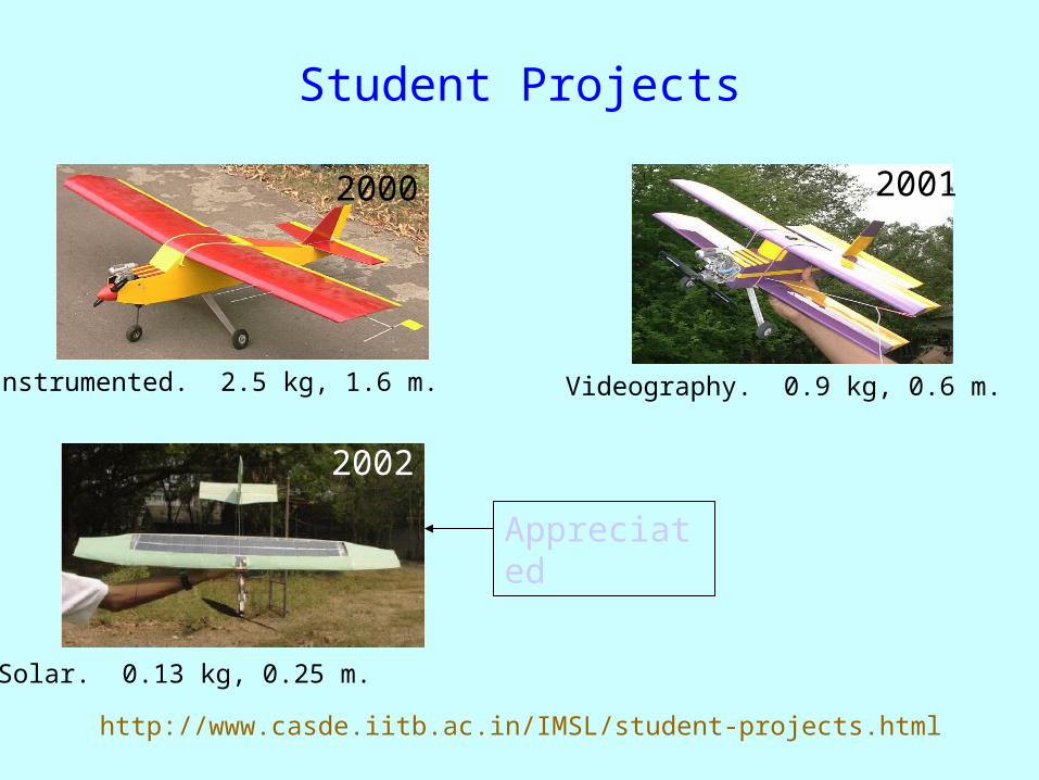
Student Projects
Instrumented. 2.5 kg, 1.6 m.
2000
Solar. 0.13 kg, 0.25 m.
2002
Videography. 0.9 kg, 0.6 m.
2001
http://www.casde.iitb.ac.in/IMSL/student-projects.html
Appreciated
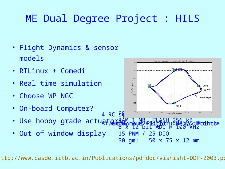
ME Dual Degree Project : HILS
• Flight Dynamics & sensor models
• RTLinux + Comedi
• Real time simulation
• Choose WP NGC
• On-board Computer?
• Use hobby grade actuators
• Out of window display
68332 @16 MHzRAM 1 MB, FLASH 256 kB8 x 12 bit ADC @ 100 kHz15 PWM / 25 DIO30 gm; 50 x 75 x 12 mm
4 RC servo actuators
Aileron, elevator, rudder, throttle Overflying Mumbai
Autonomous Flight : 4 Way Points
http://www.casde.iitb.ac.in/Publications/pdfdoc/vishisht-DDP-2003.pdf

Flapping Wing Flight
Dual-Degree Project in Aero: Flapping wing
• Unsteady aerodynamics for prescribed motion
• Aero elastic analysis for prescribed actuation
• Wing construction - Polyurethane foam. (IDC)
• Actuation mechanism for testing. (Robotics)
B. Tech Project in Robotics(Robotics group)
• Mechanism design
• Kinematics prescribed
• Loads prescribed

Awareness Creation - 2003
• January - CEP in Applied Mechatronics
• February - 3rd Meeting of SIG-MDO
• April - Workshop on MDO @DRDL
• August - Brainstorming on System Analysis
• September - Int. Conf. MSO-DMES

We also!
• Traveling Course on Design, Build and Fly. (CASDE+ADA) Student Projects as Case Studies.
http://www.casde.iitb.ac.in/IMSL/des-bld-fly.html
– Naval Institute of Aeronautical Technology, Cochin. – Dept. of Aerospace Engineering, MIT, Chennai – Dept. of Aerospace Engineering, Parks College of Eng.,Coimbatore
• AeSI Wright Flyer Design Competition. (CASDE+ADA) http://www.casde.iitb.ac.in/we-also/des-comp/

We also!
• AeSI Schools Outreach Programme. (CASDE+ADA) 30 events, 103 Schools, 5,600 students (Good part of events by CASDE) http://www.casde.iitb.ac.in/we-also/school-outreach/
Arya explaining the intricacies of flight mechanics

http://www.casde.iitb.ac.in/MDO/

Systems Engineering Process
Requirements to lower level
Context
Solution from lower level
SuperSystem
System
SubSystem
Level-3Analysis
Level-2Analysis
Level-1Analysis
Focusof CASDE
• Level – 1 : Good understanding of system; knowledge base, heuristic; Computationally less expensive; Usually not available for new systems.• Level – 3 : Physics based modeling; computationally intensive, applicable to new systems (V&V?)

CASDE Activities
Research activity
– High fidelity models in design loop ( CFD, . .)
– Multi-Disciplinary Analysis (MDA) leading to Multi-disciplinary Design Optimization (MDO)
Level-3Analysis
Level-2Analysis
Level-1Analysis

Challenges!
• Human / Admin– People coming together (Design, A/D, Str,
Prop, Controls)
– Synchronizing funds (taken care of by ARDB)
• Technical– Non-availability of disciplinary codes
– Neither here nor there!

MDO Elements
• Architectures
• Sensitivity Analysis
• Surrogate Modeling
• Variable Complexity

MDO Elements
• Architectures
• Sensitivity Analysis
• Surrogate Modeling
• Variable Complexity
Optimizer
How are the couplingshandled?
System Analysis

MDO Elements
• Architectures
• Sensitivity Analysis
• Surrogate Modeling
• Variable Complexity
How are the couplingshandled?
System Analysis
X F
• dF/dX? f/X, f/Y . . . dF/dX• How to evaluate f/x?
~ Finite difference~ Continous/Discrete Adjoint ~ Automatic Differentiation
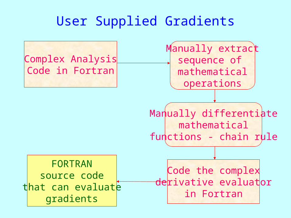
User Supplied Gradients
Complex AnalysisCode in Fortran
Manually extractsequence of mathematical
operations
Code the complex derivative evaluator
in Fortran
Manually differentiatemathematical
functions - chain rule
FORTRANsource code
that can evaluategradients

User Symbolic Maths
Manually extractsequence of mathematical
operations
Use symbolic math packages to automate derivative evaluation
Code the complex derivative evaluator
in Fortran
Complex AnalysisCode in FORTARN
FORTRANsource code
that can evaluategradients

Automatic Extraction of Formulae
Parse and extract the sequence
of mathematical operations
Use symbolic math packages to automate derivative evaluation
Code the complex derivative evaluator
in Fortran
Complex AnalysisCode in FORTARN
FORTRANsource code
that can evaluategradients

Gradients by ADIFOR
Complex AnalysisCode in FORTARN
FORTRANsource code
that can evaluategradients
Automated Differentiation
Package

ADIFOR Ver 2.0
• First applied to VLM• Recently to 3-D Euler
– Multiblock, Structured grid
– Central difference, FVM
– JST scheme of artificial dissipation.
– Multistage Runge-Kutta schemes.
– Implicit residual smoothing and local time stepping
Original
CodeADIFORed Code
No of lines 4,090 11,889
Exec. time (min)
6.58 28.25
Codex f
ADIFORed Code
x f, df/dx
ADIFOR
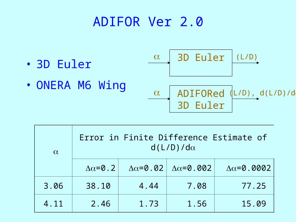
ADIFOR Ver 2.0
• 3D Euler
• ONERA M6 Wing
3D Euler (L/D)
ADIFORed3D Euler
(L/D), d(L/D)/d
Error in Finite Difference Estimate of d(L/D)/d
=0.2 =0.02 =0.002 =0.0002
3.06 38.10 4.44 7.08 77.25
4.11 2.46 1.73 1.56 15.09

MDO Elements
• Architectures
• Sensitivity Analysis
• Surrogate Modeling
• Variable Complexity
• Response Surfaces?• Design of Experiments
• Design & Analysis of Computer Experiments• Designs?
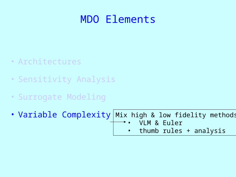
MDO Elements
• Architectures
• Sensitivity Analysis
• Surrogate Modeling
• Variable ComplexityMix high & low fidelity methods
• VLM & Euler• thumb rules + analysis

Design / MDO Studies
– WingOpt
– 3D Duct
– Hypersonic Vehicle
Design under uncertainty +
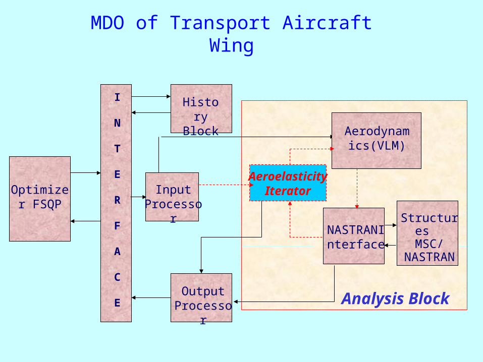
MDO of Transport Aircraft Wing
Analysis Block
AeroelasticityIteratorOptimizer
FSQP
I
N
T
E
R
F
A
C
E
History Block
Input Processor
Output Processor
Aerodynamics(VLM)
Structures MSC/
NASTRANNASTRANI
nterface

3-D Duct Design
Entry Exit Location and shape known
Geometry of duct from Entry to Exit ?
• Pressure Recovery?• Distortion?• Swirl?
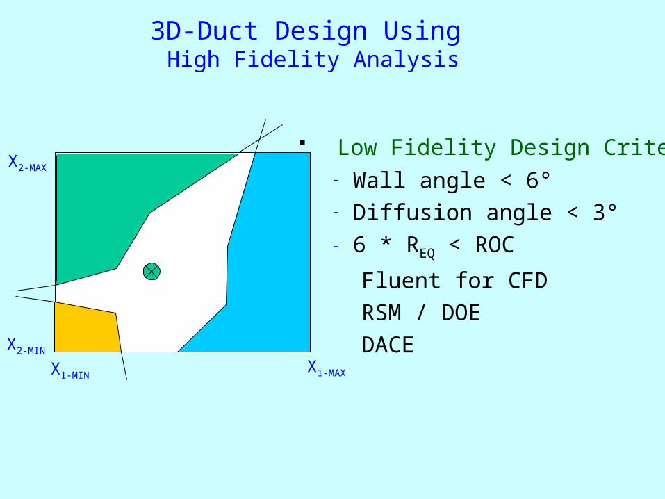
3D-Duct Design Using High Fidelity Analysis
Low Fidelity Design Criteria- Wall angle < 6°- Diffusion angle < 3°- 6 * REQ < ROC
Fluent for CFD RSM / DOE DACE
X1-MINX1-MAX
X2-MAX
X2-MIN
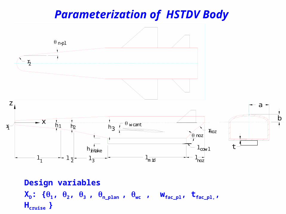
Parameterization of HSTDV Body
Design variables
XD: {1, 2, 3 , n_plan , wc , wfac_pl, tfac_pl,, Hcruise }
z
x
l l
h h
l l
wcanth
l
r
l
noz
cowl
noz
1 2 3
1 32 mid noz
1
h intake
r
n-pl
r2
a
b
t

Hypersonic Vehicle – Discipline Interactions
Ext. CompressionModel : AM1
Ext. ConfigurationModel : AM2
Aero Model : AM3
Trim Model : AM4
Thrust Model : AM5
Performance Model : AM6
Y1: l1, l2, l3, h1, h2, h3
Y2: ma , MI, , pst
Y3: (X,Y,Z)Y4: TOGW , C.G., Vol, Fuel mass
Y5: CN, Cm, CA
Y6: TOGW_up, T , T , D
Y7: Th_deliv, Lp, Mp
Y8: Cruise Range
1
2
3
n_pl
w_c
SW
ST
Hcr
Input variable Analysis Model Output
n_pl, SW
1…, Hcr
Variables not sharedShared variables
Y1
Y1… Response from AM1 required as input in AM2

MDO-Framework
Database
ConfigurationServer
ExecutionManager
MDOController
NameServer
DataServer
OPT1
Optimizer Manager
OPT2 OPT3
AM1
AnalysisManager
AM2 AM3
GUI
Control
Data

http://www.casde.iitb.ac.in/MDO/

Publications
2000 2001 2002 2003
Journal 0 1 3+2 1+1
InternationalConferences
0 1 6 5
Core faculty = 4

Analysis for Design
Design
z = design variablesf = objectiveh = equality constr.g = inequality constr.R = residue
Interface
AnalysisR(z,p)=0
Optimizer
z f, h, g
z p
Optimization
Analysis
Optimizer
z f, h, g
z = design variablesf = objectiveh = equality constr.g = inequality constr
MDO
z = design variablesf = objectiveh = equality constr.g = inequality constr.R = residue
Analysis-1R1(z,p1)=0
Interface
Optimizer
z f, h, g
z p
Analysis-2R2(z,p2)=0
Y12
Y21

MDO-ArchitecturesMDO
z = design variablesf = objectiveh = equality constr.g = inequality constr.R = residue
Interface
Optimizer
z f, h, g
z p
Analysis-1R1(z,p1)=0
Analysis-2R2(z,p2)=0
Y12
Y21
Analysis-1R1(z,p1)=0
Analysis-2R2(z,p2)=0
Y12
Y21
z p

MDO-Architectures
Analysis-1R1(z,p1)=0
Analysis-2R2(z,p2)=0
Y12
Y21
z p
p
Analysis-1R1(z,p1)=0
Analysis-2R2(z,p2)=0
Y12, Y21z 1 = Y12 - Y12* 2 = Y21 - Y21*
Analysis
Evaluator
Y12*
Y21*

MDO-ArchitecturesMDO
z = design variablesf = objectiveh = equality constr.g = inequality constr.R = residue
Interface
Optimizer
z f, h, g
z p
Analysis-1R1(z,p1)=0
Analysis-2R2(z,p2)=0
Y12
Y21
MDO
z = design variablesf = objectiveh = equality constr.g = inequality constr.R = residue
Interface
Optimizer
z, y12, y21
f, h, g1, 2
p1, 2
Analysis-1R1(z,p1)=0
Analysis-2R2(z,p2)=0
z, y12, y21

3D-Duct Design Using High Fidelity Analysis
X1-MINX1-MAX
X2-MAX
X2-MIN
Low Fidelity Design Criteria- Wall angle < 6°- Diffusion angle < 3°- 6 * REQ < ROC
Fluent for CFD RSM / DOE DACE
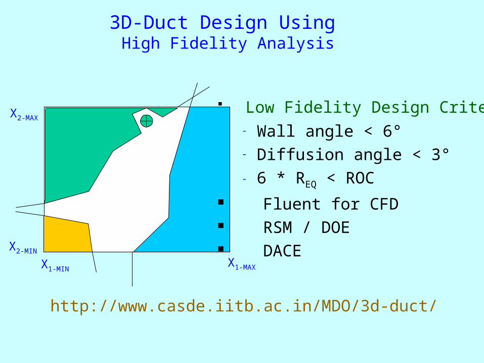
3D-Duct Design Using High Fidelity Analysis
X1-MINX1-MAX
X2-MAX
X2-MIN
http://www.casde.iitb.ac.in/MDO/3d-duct/
Low Fidelity Design Criteria- Wall angle < 6°- Diffusion angle < 3°- 6 * REQ < ROC
Fluent for CFD RSM / DOE DACE
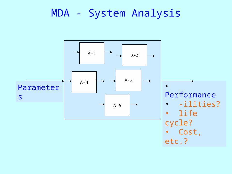
MDA - System Analysis
• Performance• -ilities?• life cycle?• Cost, etc.?
Parameters
A-2
A-4
A-1
A-5
A-3
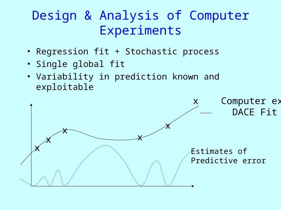
Design & Analysis of Computer Experiments
• Regression fit + Stochastic process• Single global fit• Variability in prediction known and exploitable
xx
xx
x
Estimates of Predictive error
x Computer exp DACE Fit

Building Models Using DACE
xx
xx
x
5% predictive error
x = Computer exp DACE Fit
xx
x
Use multi-modal GA to identify ‘n’ highest peaks.Test if they are higher than 5%Add computer experiments at those spots
Design - Publications
Journal of Aircraft Volume 40 Number 4
July 2003
• Total number of papers - 22• Number of papers addressing design - 4


