Download - Em Dec 2015

EM - Interview (p. 28)
Gaur DattatreyaVP & Head of Business UnitRobert Bosch Engg & Business Solutions
FOCUS Medical machining P. 30
EVENT REPORT Solid Edge University 2015 P. 60
EFFICIENT MANUFACTURING
www.efficientmanufacturing.in
VOL 07 | DEC 2015
Also
ava
ilabl
e in
Chi
na, T
aiw
an, S
inga
pore
, Mal
aysi
a, T
haila
nd &
Hon
g Ko
ng
Driving maximum value from assets
ASSET PERFORMANCE MANAGEMENT


Ready-to-install cable carrier systems:e-chains® ex® cables
= readychain®
readychain®is a pre-harnessed systemthat is ready to plug-and-play upon delivery. Available from 24 hours!
... plastics for longer life®
igus® (India) Pvt. Ltd. 36/1, Sy. No. 17/3 Euro School Road,Dodda Nekkundi Industrial Area - 2nd StageMahadevapura, Bangalore -560048,Karnataka, IndiaPhone : +91 - 80 - 45127800, Fax : +91 - 80 - 45127802


GEAR UPFor Gear, Spline & Rack Manufacturing
VARGUS INDIA VARGUS Ltd.Unit Nos. 16 & 20, 1st FloorMega Centre
Tel: +91 21356 [email protected]
Pune - Nasik Highway, Chakan, Pune - 410501
VARGUS INDIA VARGUS Ltd.Unit Nos. 16 & 20, 1st FloorMega Centre
Tel: +91 21356 [email protected]
Pune - Nasik Highway, Chakan, Pune - 410501
EASIER withStandard Gear Milling Inserts
* DIN 3972 Basic Pro�le I
U Style | 3 Cutting Edges

ED ITOR IALED ITOR IAL
7EM | D e c 2015
Here we are, the last month of the year. There were some ups and downs in the industrial growth in this year. But India still remains as a new growth leader in Asia-Pacific, having overtaken China. With the Prime Minister’s ‘Make in India’ initiative to place India on the world map as a manufacturing hub and give global recognition to the Indian economy, India’s manufacturing sector could touch US$ 1 trillion by 2025. There is potential for the sector to account for 25-30% of the country’s GDP and create up to 90 million domestic jobs by 2025. Instead of being a dumping ground for the companies across the world, India could attain a unique position of manufacturing excellence by this programme, for building worldclass products for our own consumption as well as for export.
This calls for acquiring an ability to respond quickly and effectively to the changing demand conditions of the domestic as well as international markets. The zero defect mindset is the necessity to ensure the success of `Make in India’ programme, besides fostering technical excellence, with skill enhancement in our workers. Moreover, there is an acute need to improve India’s ailing infrastructure scenario and defunct logistics facilities. In short, it is a long road ahead!
As we approach the end of the year, it is always a good time to regroup, reexamine and revisit your strategies and tactics—both from a business as well as an operational perspective. While the future may not look so promising with a very volatile global economy, it’s always worth taking advantage of every opportunity you have to try new things. Finally, with all the unrest and intolerance in the world, we hope you find the success! Best wishes!
Shekhar Jitkar Publisher & Chief [email protected]
Responding quickly & effectively“While the future may not look so promising with a very volatile global economy, it’s always worth taking advantage of every opportunity you have to try new things”
Sonali KulkarniPresident & CEOFanuc India
Dr Wilfried AulburManaging PartnerRoland Berger Strategy Consultant
Vivek SharmaManaging DirectorYamazaki Mazak India
N K DhandCMDMicromatic Grinding Technologies
Dr K Subramanian President, STIMS Institute, USATraining Advisor, IMTMA
S RavishankarManaging DirectorDMG MORI India
Raghavendra RaoVice PresidentManufacturing & Process ConsultingFrost & Sullivan
Dr P N RaoProfessor of Manufacturing TechnologyDepartment of TechnologyUniversity of Northern Iowa, USA
Satish GodboleVice President, Motion Control DivSiemens Ltd
Vineet SethManaging DirectorIndia & Middle EastDelcam Plc
EDITORIAL ADVISORY BOARD
Overseas Partner:
China, Taiwan, Hong Kong & South-East Asia
8 EM | D e c 2015
CONTE N T S
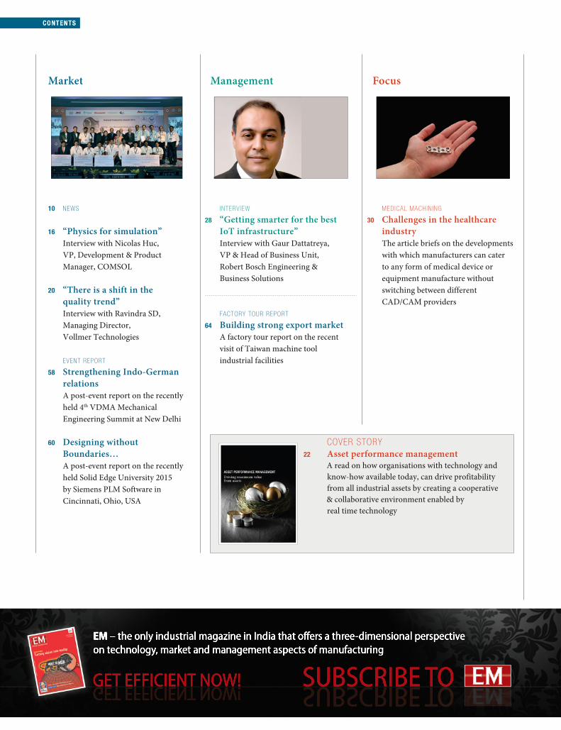
COVER STORY22 Asset performance management A read on how organisations with technology and
know-how available today, can drive profitability from all industrial assets by creating a cooperative & collaborative environment enabled by real time technology
MEDICAL MACHINING
30 Challenges in the healthcare industry
The article briefs on the developments with which manufacturers can cater to any form of medical device or equipment manufacture without switching between different CAD/CAM providers
CONTE N T S
Market Management Focus
10 NEWS
16 “Physics for simulation” Interview with Nicolas Huc,
VP, Development & Product Manager, COMSOL
20 “There is a shift in the quality trend”
Interview with Ravindra SD, Managing Director, Vollmer Technologies
EVENT REPORT
58 Strengthening Indo-German relations
A post-event report on the recently held 4th VDMA Mechanical Engineering Summit at New Delhi
60 Designing without Boundaries…
A post-event report on the recently held Solid Edge University 2015 by Siemens PLM Software in Cincinnati, Ohio, USA
INTERVIEW
28 “Getting smarter for the best IoT infrastructure”
Interview with Gaur Dattatreya, VP & Head of Business Unit, Robert Bosch Engineering & Business Solutions
FACTORY TOUR REPORT
64 Building strong export market A factory tour report on the recent
visit of Taiwan machine tool industrial facilities

9EM | D e c 2015
CONTENTSCONTENTS
Technology
New Products
69 Drilling tools; Flexible clamp cables; Smart 3D sensors; Tribological filaments;
70 Centring points for drill bits; Shoulder milling tools; CAD/CAM sheet metal software; Compact mechatronic module;
71 Face milling cutter; Laser processing machine; Pneumatic drive machine; Precision hardened & ground flanges
Columns
07 Editorial 08 Contents 72 Highlights – Next issue 72 Company index
SUPPLY CHAIN MANAGEMENT
36 Lean guiding principles for the supply chain
This article talks on Built-in Quality, one of the lean guiding principles to develop a lean culture in a supply chain operation
GEAR MANUFACTURING
42 Ready for large tasks The article discusses the large industrial
measuring centres for gears adapting to the current market needs
Cover image courtesy: Shutterstock
CUTTING TOOLS
48 Taking hole deburring to new depths
A read on how the new Mechanical Edge Profiting process keeps exit burrs from negatively impacting tool rigidity, machining accuracy and tool life in deep, small-diameter through holes
MANUFACTURING IT
52 Achieving program excellence A read on how aerospace & defense
firms achieve program excellence with Siemens integrated verification management system

10 EM | D e c 2015
MARKE T | NEWS
COMSOL has recently released COMSOL Multiphysics® 5.2 that provides
simulation community the only fully integrated environment for creating
simulation apps. It delivers new features, improved stability & robustness
and faster execution. Major upgrades to the application builder available in
COMSOL Multiphysics include the new editor tools for easy creation of user
interface components, commands
for dynamic updates of graphics,
and more control over the
deployment of simulation apps.
Running simulation apps using
COMSOL server in a corporate
network or in the cloud is now up to
five times faster. Many updates, new
features and simulation application
examples are also available for the
add-on electrical, mechanical, fluid,
and chemical products. “We leveraged the Application Builder to more
efficiently communicate complex design ideas across multiple simulation
and process departments, which has allowed app users to easily explore
the outcome of proposed designs,” said Borja Lazaro Toralles, Research
Engineer on the Manufacturing Technology Centre (MTC) simulation team.
Its features include ability to update graphics while running an app.
The software delivers new features, improved
stability, robustness & faster execution
COMSOL releases Multiphysics® 5.2
EDM Productivity Forum (EPF) recently held its EDM summit across Mumbai,
Pune, Nasik & Aurangabad.
The 4-day event witnessed
over 250 people from over
150 tool rooms visiting the
forum. The event was jointly
supported by Makino India
and GF Machining Solutions
and provided a platform for
sharing best practices in
EDM machining. Industry
experts like Stephen Harris
from MWI, USA & N Konishi
from TOKAI Carbon made technical presentations on the EDM process.
Sadananda Koppalkar, Head - Business Development, Makino, used the
platform to share inputs on how to improve the productivity on EDM
machines. It also featured some of the best tool rooms in this region, where
there were insights on the best practices & improvements in the EDM section.
Also, there was the first ever benchmarking study done by Prime Industries
amongst its clients across 4 cities. Over 35 clients participated in this study
and winners were chosen in areas of best MRR, lowest wear and best
surface finish achieved on EDM.
The summit provided a platform to award best
practices in EDM machining
EDM summit organised by EDM Productivity Forum BFW launches tech centre at Kolhapur
BFW recently inaugurated a tech centre at Kolhapur to meet the growing
needs of customers. It will showcase cutting edge new products for the
customers’ next-gen requirements.
The company will position dedicated
service engineers and stocking of the
spares closer to customers and,
thereby, provide effective after-sales
and service. In terms of application,
engineers stationed at the tech centre
will provide solutions to challenging
problems faced by customers. For
trainings, company officials will
conduct customised & comprehensive
training programs for production
processes, engineering applications,
maintenance, etc. Ganesh Technologies
is the channel partner for Kolhapur. With market knowledge, sales expertise
and customer relationships developed over two decades, this association
will further strengthen the Kolhapur centre. According to Ravi Raghavan,
CEO, BFW, “To meet the needs of customers in Kolhapur like sound
castings, Mahabal metals, Mourya Industries, Caspro Metals, General
Machine Tools, etc, we have decided to strengthen our presence here.”
According to Raghavan, the centre
will strengthen the company’s
presence in Kolhapur to meet the
customers’ next-gen requirements
Fair Friend Group acquires MAG Group
Fair Friend Group (FFG) has recently acquired MAG Group, a leading
machine tool manufacturer for the automotive industry, which
strengthens it position as
one of the world’s leading
machine tool suppliers.
Speaking on the occasion, Dr
Reiner Beutel, CEO, MAG,
said, “MAG will benefit from
the global footprint and
financial strength of FFG,
while our customers will
benefit from the sharing of
know-how and technology
between our companies, increased production capabilities as well as
local service wherever they are”. With MAG’s seven production facilities,
FFG increases the number of machine tool factories to 51 across the
globe, now covering Taiwan, Germany, Italy, Hungary, Japan, South
Korea, China, Switzerland, India and USA, with a total of 32 brands.
According to Jimmy Chu, Founder & Chairman, FFG, “I am happy to
welcome MAG and its employees to our large family. I am confident that
the integration of MAG into FFG will be beneficial for all of us, and for
our customers and suppliers.”
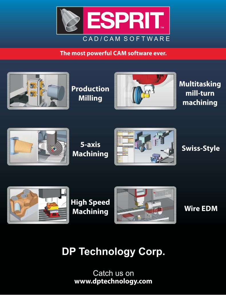
High Speed Machining
5-axisMachining
Production Milling
Multitasking mill-turn
machining
DP Technology Corp.
Catch us on

12 EM | D e c 2015
MARKE T | NEWS
Milacron India inaugurated its Extrusion Open House at the Ahmedabad
facility recently. It included the demonstration of an extrusion line in live
production of cPVC pipes. At the event, Milacron received two orders for
India-built pipe extrusion systems from local customers. The orders were
for complete systems and
included extruder, controller, die/
head, cooling/sizing tank, puller,
cutting/saw and accumulation
table. The first system will ship
before the end of 2015 and the
second system is scheduled to
ship in Q1 2016. Speaking at the
event, Brian Marston, VP & GM,
Global Extrusion Business, stated,
“The conical twin screw counter
rotating extruder producing cPVC pipe is one of our most popular extrusion
technologies and we anticipate a strong demand for these machines in
India and surrounding regions”. The three-day event catered to the needs
of India’s growing construction industry. The extruder produced ¾ inch
cPVC pipes and an injection moulding machine cPVC line Servo 150 was
engaged in the production of cPVC fittings.
Milacron India inaugurated its Extrusion
Open House at Ahmedabad
Milacron India launches extrusion capabilities
The HaasTec will soon take place in Pune, where innovative & affordable
Haas CNC machine tools will be on view. Machines like UMC-750 five-
axis universal machining centre and ST-35 big bore CNC lathe will be on
display. All machine tools on display will be powered and performing
demonstrations, cutting metal. Haas specialists from the HFO will be
available to guide visitors through the demonstrations. The machines to
be displayed at the event include UMC-750 five-axis vertical machining
centre offering a capacity of 762 x 508 x 508 mm in the X, Y and Z-axis
respectively; ST-35 big
bore CNC lathe that can
accommodate bars up to
102 mm in diameter and
offers a capacity of 533
(dia) x 660 mm (length)
with 806 mm of swing;
ST-10Y turning centre
with Y-axis; DT-1 drill tap
machine with new 30
taper 15,000 rpm spindle,
VF-2 VMC, VF-2SS, mini
mill and VF-7/50 VMC.
All machine tools on display will be powered and
performing demonstrations
HaasTec to be held at PuneFrost & Sullivan announces Sustainability 4.0 Awards
Frost & Sullivan has recently announced the launch of its Sustainability
4.0 Awards 2016, which will take place on May 27, 2016 at Mumbai. The
erstwhile Green Manufacturing Excellence Awards is a prestigious awards
banquet that has become a premier platform acknowledging companies
for their work in sustainability requirements across their value chains.
The impact of transformational changes, unexpected disruptions in
technologies and established operating systems has shifted the focus
of industries toward sustainable practices. With an increasing number
of enterprises embracing approaches to sustainable development, the
need to support these businesses and recognise their efforts has become
paramount. Announcing the launch of the 7th edition of the awards
banquet, Nitin Kalothia, Director—Manufacturing & Process Consulting,
Frost & Sullivan, said, “The parameters of perpetuity of a business
has moved beyond revenue generation and management’s innovative
thinking. To survive and thrive in today’s volatile ecosystem, corporates
in India are imbibing sustainable development as part of their long-term
strategy.” The sustainability program was instituted in 2009.
Grind Master bags the SME Business Excellence Award
Grind Master has recently received the SME Business Excellence Award in
the mid-corporate segment under Engineering & Machinery sector organised
by Karur Vysya Bank and Dun &
Bradstreet (D&B) at New Delhi. The
event, attended by eminent
business leaders and senior
government officials, also included
the release of the publication
“Leading SMEs of India 2015”. “It
gives me great satisfaction that we
are emerging on a national and
international stage as a trustworthy
& passionate machine builder,” said
Sameer Kelkar, Executive Director,
Grind Master, while receiving the award. Grind Master has been growing at
a phenomenal rate in the past few years, closing FY14-15 with a turnover
of more than `120 crores. As one of the large machine tool builders in India,
it qualified in the “mid-corporate” category, thus, reflecting the
transformation into a professionally managed business. Recently completing
the 50th machine in China, the company has created a brand known for
expertise & innovation in metal finishing internationally.
Sameer Kelkar felicitated with
the award


14 EM | D e c 2015
MARKE T | NEWS
During EMO 2015 in Milan, Mikrosa rceieved the i-NOVO Award from the
online industrial fair DirectIndustry for its centreless external cylindrical
grinding machine KRONOS S 250. The machine is designed for high-
volume production in the high-precision segment and for the plunge and
throughfeed grinding of workpieces in
the diameter range of 1.5 to 35 mm,
and is constructed with a plunge grind
width of up to 245 mm. Its new design
is geared systematically towards
ergonomy and user-friendliness. The
control panel, for example, has quick
and simple height adjustment. So, the
operator can adapt it to his own needs
and avert potential postural defects.
The machine’s sliding doors, which
can be opened wide, are equipped
with ergonomic door handles featuring an adjusted grip profile. To simplify
the cleaning process, the machine’s surface structures were improved
and the materials used were optimised. The centreless external cylindrical
grinding machine is fitted with a multi-coloured signal light with an
integrated flash function, thereby, providing optimum status visibility.
KRONOS S 250’s new design is
geared systematically towards
ergonomy and user-friendliness
Mikrosa wins i-NOVO Award
National Productivity Summit 2015
Indian Machine Tool Manufacturers’ Association firmly believes that it is
necessary to recognise those
who have contributed to
productivity improvement in
Indian industries and to
encourage more to emulate
these pioneers. With this
objective, IMTMA hosts the
National Productivity Summit
every year. The summit this year
was recently organised at
Gurgaon.
The event showcased the
best productivity improvement
projects in metal working
industries, which have excelled
in achieving superior performance through sustained productivity
improvements. The two-day event witnessed around 300 participants from
102 companies. L Krishnan, President, IMTMA, presented the welcome
address, where he spoke on innovative approaches to address productivity
challenges, new ideas and concepts. Presentations were put up by teams
from Maruti Suzuki, Honda Cars, Hitech Gears and Sartorius India Group.
During the event, Dr Saraswat, Hon’ble Member, National Institution of
Transforming India (NITI) Aayog, briefed on the current Indian economic
scenario, the challenges and opportunities
lying ahead. He then impressed upon the
importance of productivity and manufacturing
to the growth of the nation, in conjunction
with the drive of the government on the ‘Make
in India’ campaign, to equip the Indian
manufacturing fraternity and scale them to
greater heights in the global arena.
Leading firms such as Ashok Leyland,
Bajaj Auto, Bosch, Keihinfie, Lucas TVS,
Mahindra & Mahindra, Maruti Suzuki, Tata
Motors, TVS Motor and Wabco India presented
their case studies on productivity practices,
all of which contested for IMTMA – ACE
Micromatic Productivity Championship
Awards 2015 that gave away cash awards of ` 10 Lakhs.
Wabco India, TVS Motors, Bajaj Auto, Keihinfie, Lucas TVS and SKF India
were adjudged the winners of the IMTMA - ACE Micromatic Productivity
Championship 2015 Awards. Further, a Vox Populi award was given to
TVS Motors. Also, plant visits to Hero Motocorp, Sona BLW Forging,
Hitech Gears and Honda Motorcycles & Scooters India were arranged a day
prior to the event.
The event showcased the best productivity improvement projects in
metal working industries
German machine tool industry performing valiantly
In the third quarter of 2015, order bookings in the German machine tool
industry fell by 1%, compared
to the preceding year’s
equivalent period. Domestic
orders rose by 9%, while
demand from abroad was
down by 7%. In the first nine
months of 2015, order
bookings stagnated compared
to the previous year. Domestic
orders fell by 3%, with demand
from abroad up by 1%.
According to Dr Wilfried
Schäfer, Executive Director—
VDW, Frankfurt, “In the year’s third quarter, our sector was boosted by
orders from Germany itself and from the Eurozone. Western Europe proved
to be the motor for demand in the German machine tool industry. The
Americas, by contrast, were disappointing, with orders down across the
board. Asia, as a whole, scored with modest growth. Good business with
South Korea & Japan, however, was offset by a substantial minus in
orders from China, the biggest market.”
Order bookings and turnover remain at
a higher level
German Machine Tool IndustryOrder bookings and turnover remain at a high level
0
40
80
120
160
200
240original values
12-months movingaverage
Order Intake [Index, nominal]
2000 2002 2004 2006 2008 2010 2011 2012 2013 201519991997 19981996 2003 2005 2007 20092001 2014
02.11.2015 Verein Deutscher Werkzeugmaschinenfabriken e.V. (VDW)
Note: Index basis shipments 2010=100, data until September 2015Sources: VDW, VDMA
Order Intake, %-change to previous year3Q 2015 1-3Q 2015
Total -1 0Domestic +9 -3Foreign -7 +1


16
MARKE T | I N TER V I EW
EM | D e c 2015
Tell us more about the simulation software models that can be used to predict effects of heat transfer and thermal stress and to improve thermal performances of a given application? Heat transfer modeling in COMSOL Multiphysics® covers the 3 means of heat transfer: conduction, convection and radiation. Heat transfer by conduction handles non-linear material properties which can be, for example, temperature dependent. It also supports anisotropic material properties which is often needed for composite material modelling. It can be combined with the “Curvilinear Coordinates” interface to define the orientation of anisotropic material that have complex geometry configurations. Heat transfer by convection is supported for laminar and turbulent flow regimes, it can be combined with phase change to achieve high cooling performances. Heat transfer by radiation is implemented for surface-to-surface radiation and radiation semi-transparent media. All the heat transfer capabilities can be freely combined with all our structural mechanics capabilities for thermal stress modeling.
The ability to combine many areas of physics for simulation purposes is the latest innovation of COMSOL. Can you elaborate more on it?COMSOL Multiphysics® has been designed to combine multiple physics from the beginning. This is not something that has been introduced recently, it is a pillar of the software. We are using a patented method for assembling the finite element discretisation of arbitrary equations. It offers an optimal framework for the numerical treatment of multiphysics problems.
With this method, COMSOL Multiphysics® is able to treat all the physics (and the corresponding equations) in a coupled manner. For strongly coupled physics, this is the key to have high convergence rates and high accuracy. Models with strongly coupled physics correspond to configurations where two or more physics interact which each other and none of them is leading the other ones. For example, models with Joule heating where the electric properties are greatly influenced by the temperature. Natural convection is another example when the flow and the temperature are strongly coupled.
What is new in COMSOL Multiphysics® version 5.2?A lot of efforts has been put to implement hundreds of enhancements on existing capabilities. This makes COMSOL Multiphysics® 5.2 the most stable and finished product we ever released. Of course, there are new functionalities, but it is important to stress that great attention was paid to details and feedbacks to improve the software in all aspects (accuracy, performance, usability). The version 5.2 provides simulations experts the Application Builder, a mature simulation app design. It is a highly productive interface
for app design that makes it possible for experts to embed their expertise in COMSOL Apps. COMSOL Server™ allows to deploy their simulation applications and have them used by users everywhere.
Which are the industry segments that COMSOL is targeting globally and in India for the latest version of Multiphysics software?One strength of COMSOL is that COMSOL Multiphysics® is used for a wide range of applications in several different industries. It is used in automotive industry, for MEMS design, for defense and electronic industry
as well as in food industry, medical applications, etc.
How challenging it is to make the industry receptive to scientific modelling? My experience is that every industrial player has a number of challenges to address and that in some cases modelling and simulation provides a solution. In this case, scientific modeling is easily adopted. When scientific modeling doesn’t provide a satisfactory solution or when there is no identified challenge for it, then it’s almost impossible to convince someone to invest in something that does bring any identified benefit. I would say that the industry is already rather receptive to scientific modelling. The fact that simulation market is continuously growing tends to confirm that. I believe that the challenge is on our side. The more industrial challenges we address the more the industry will use scientific modelling and simulation. ☐
“Physics for simulation”Nicolas Huc, VP of Development & Product Manager, COMSOL, briefs on
combining many areas of physics for simulation purposes and features of the new version of COMSOL Multiphysics®, and shares his views on challenges in scientific
modelling, in an interview with Shekhar Jitkar. Excerpts…

HONED BY
OF EXPERIENCE YEARS
OF
HONED BY
EXPERIENCE YEARS
INNOVATIVE METALWORKINGFLUID SOLUTIONS FROM QUAKER
Metalworking is much more than just producing parts. It’s about understanding your processes and choosing the right coolant, cleaner, stamping fluid or rust pre-ventive. It’s about every element doing its job. You need a partner who can help keep things running and keep them running at their best. That’s why you need Quaker. No challenge is too big for relentless innova-tion, hard work and a sincere desire to help you maximize your productivity and improve your bottom line. It’s our obsession – and inside everything we do. Because at the heart of the metalworking industry, you’ll find us.
It’s what’s inside that counts.®
Quaker Chemical India Private Limited7B, Pretoria Street,Kolkata- 700071 | India T : 91.33.2282.5414E : [email protected]: quakerchemindia.com


20
MARKE T | I N TER V I EW
EM | D e c 2015
Can you brief us on the latest developments happening at your end when it comes to handling sharp tools, saw blades, tooth shapes or tool geometries?For sharp tools, the machines are nearly stabilised to the saturation level, although there is still room for improving machine speed. The machines are stabilised in terms of technology. For rotary tools, Vollmer had launched a new concept for tool & cutter grinder at the GrindTec 2014, where Vgrind 160 was introduced. In the existing product portfolio for the circular saw blade grinding, we have also introduced new models to streamline the existing portfolio into modular machines, so that all machines look identical and have standardised parts & easy inter-changeability between machines.
For saw blades, we have a range of machines. We make from the simplest of hydraulic machines to sophisticated 8-9 axis machines that can be automatically operated. We have also developed band saw blade grinding machines. In the area of tool geometries for saw blades, we always strive to improve on the hardware & software on our machines, so that the tools are processed in faster & simple manner. The new tooth shapes are derived by our customers based on the applications in question & we develop the machines to handle these tooth geometries.
How does R&D work in your domain? We have an R&D team of 70 people working in Germany. They work towards product development—both on existing & new products depending on the market requirements. CNC tool and cutting grinders are the new introductions from the company. Besides, we are working towards a few new technology innovations.
How do you look at the current scenario in the manufacturing industry in India? What are the major challenges in the industry?In general, the market is witnessing many ups and downs.
We saw a tough year in 2014. But towards the end of the year, our business picked up, and since then we have seen a good inflow of orders and the turnover has been good too. However, price is a major challenge in our industry. So, we have produced low cost machines with a reasonably good quality. Also, what customers are looking at and how many
saw blades do they want to process in a day helps us to recommend machines according to the technology level.
Can you elaborate on the demand & technological trends in your sector? How are the latest developments helping in creating new value for customers?In the rotary tool business, there are new technologies coming up like laser machining. Also, in medium to high-tech machines, there are some developments happening. Since price is a major influencing factor, specially in Asian markets, we keep end products in mind and develop our products
accordingly. We are serving customers in different sectors. Vollmer machines are known for quality and ease of operation. The customers have to only change the parameters based on the individual saw blades and start the machine. The machines are pre-loaded with the required software & the programs according to the customer needs, which helps them to work with our machines at ease.
Can you brief us on your global as well as Indian market trends in the near future?India is facing a crunch of reasonably skilled manpower today. So, the mindset of customers is also changing. The market is moving from labour-intensive applications to automation and, thereby, trying to minimise labour-dependency & also ensuring consistent quality. Hence, there is a shift in the quality trend as well due to automation, and Vollmer has a wide product range to address this demand from the markets worldwide. ☐
“There is a shift in the quality trend”Ravindra SD, Managing Director, Vollmer Technologies (a subsidiary of VOLLMER
Werke Germany), believes that the trend today is shifting from the use of labour-intensive applications to automation. In his interview with Megha Roy, he discusses the latest innovations
and trends in the industry. Excerpts…


22 EM | D e c 2015
COVER STO RY MA NA GEM E N T
Imag
e co
urt
esy:
Shu
tters
tock
Driving maximum value from assetsASSET PERFORMANCE MANAGEMENT
Dr Peter MartinVP, Business Value ConsultingSchneider [email protected]
COVER STO RY | MA NA GEME N T
It is becoming more important than ever for all industrial operations to drive maximum value from all assets, due to increasing financial and competitive pressures. With the technology and know-how available today, organisations can drive profitability from all industrial assets by creating a cooperative and collaborative environment, underpinned by the appropriate measures of performance and enabled by real-time technology.
22 EM | D e c 2015

23EM | D e c 2015
MANAGEMENT C OVER STORY
With the rapid rise in industrialisation came a corresponding rise in the complexity of industrial operations. Prior to the industrial revolution, most people involved in the production of goods were generalists. They had skills and abilities that crossed multiple disciplines. But with the rise of highly complex industrial operations, leaders of these companies quickly learned that the best way to manage the complexity was to train specialists in key areas of the operation. No longer was the operator of a piece of equipment responsible for the maintenance of the equipment. Rather, separate maintenance and operations departments were established. The same was true for accounting, engineering, production planning and scheduling, and a number of other disciplines.
Even within the field of engineering, multiple specialists areas were established, such as mechanical engineers, chemical engineers, electronic engineers and industrial engineers. Although creating these areas of specialty was initially critically important to getting these complex operations working effectively, it also led to today’s often disjointed industrial organisations.
With time, each of these specialised disciplines developed their own vernacular and working practices, and subsequently became islands of specialty within the overall industrial operation. And it became more and more difficult for the specialists in one island to understand and communicate with those in other islands. Perhaps the largest impact of this “island of organisation” phenomenon has been right at the operational levels in a plant. In most industrial plants, the maintenance teams and the operations teams do not cooperate very well. In many plants, they actually seem to conflict with one another as they each try to carry out their responsibilities. Since these two teams work on the same asset base in the operation, this conflict may result in suboptimal operations and reduced profitability. Many industrial operations are feeling financial and competitive pressure as never before, and it is becoming more important than ever to drive maximum value from all assets.
Root of the conflict
The conflict between maintenance and operations teams in industrial operations is not very surprising, once it becomes apparent how the performance of each team is measured.
In industrial operations in which operations and maintenance performance are measured, the most common measure for maintenance is asset availability, while the most common measure for operations is asset utilisation. A cursory analysis of these two measures clearly shows that they tend to be inverse functions. That is, when the assets are running in a reasonable manner, increasing asset availability typically requires the reduction of asset utilisation and vice versa. This presents a real conundrum to industrial plants as illustrated in Figure 1. The problem this creates is that the maintenance department and operations department have to be in conflict with each other almost by definition. And the better each team is, the greater the level of conflict.
It is difficult to identify an industrial factory or plant today in which the operations and maintenance teams really work cooperatively. This conundrum has become a major barrier to the performance improvement of many industrial operations.
Asset performance measures
Before moving to approaches for resolving the conflict, it may be helpful to evaluate asset availability and asset utilisation with respect to their appropriateness for industrial assets. One issue with these two terms is that they are not very well defined. Also, asset availability typically is measured as the percentage of time an asset is available to the operation. This is an extremely limited view. An asset may be available, but in such poor repair that it can only output a small percentage of its designed capability. Although the asset may be available it is certainly not maintained to be in the condition that it should be.
24 EM | D e c 2015
COVER STO RY MA NA GEM E N T
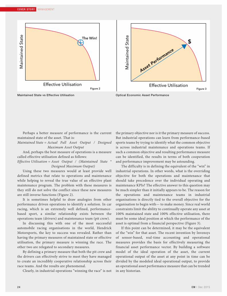
Perhaps a better measure of performance is the current maintained state of the asset. That is:Maintained State = Actual Full Asset Output / Designed
Maximum Asset OutputAnd, perhaps the best measure of operations is a measure
called effective utilisation defined as follows:Effective Utilisation = Asset Output / (Maintained State *
Designed Maximum Output)Using these two measures would at least provide well
defined metrics that relate to operations and maintenance while helping to reveal the true value of an effective plant maintenance program. The problem with these measures is they still do not solve the conflict since these new measures are still inverse functions (Figure 2).
It is sometimes helpful to draw analogies from other performance driven operations to identify a solution. In car racing, which is an extremely well defined, performance-based sport, a similar relationship exists between the operations team (drivers) and maintenance team (pit crew).
In discussing this with one of the most successful automobile racing organisations in the world, Hendrick Motorsports, the key to success was revealed. Rather than having the primary measures of maintained state or effective utilisation, the primary measure is winning the race. The other two are relegated to secondary measures.
By defining a primary measure that both the pit crew and the drivers can effectively strive to meet they have managed to create an incredibly cooperative relationship across their race teams. And the results are phenomenal.
Clearly, in industrial operations “winning the race” is not
the primary objective nor is it the primary measure of success. But industrial operations can learn from performance-based sports teams by trying to identify what the common objective is across industrial maintenance and operations teams. If such a common objective and resulting performance measure can be identified, the results in terms of both cooperation and performance improvement may be astounding.
The difficulty is in defining the equivalent of the “win” in industrial operations. In other words, what is the overriding objective for both the operations and maintenance that should take precedence over the individual operating and maintenance KPIs? The effective answer to this question may be much simpler than it initially appears to be. The reason for the operations and maintenance teams in industrial organisations is directly tied to the overall objective for the organisation to begin with— to make money. Since real world constraints limit the ability to continually operate any asset at 100% maintained state and 100% effective utilisation, there must be some ideal position at which the performance of the asset is optimal from a financial perspective (Figure 3).
If this point can be determined, it may be the equivalent of the “win” for that asset. The recent invention by Invensys of sensor-based, real-time accounting and operational measures provides the basis for effectively measuring the financial asset performance vector. By building a software model of the ideal operation of the asset, the current operational output of the asset at any point in time can be divided by the modeled ideal operational output, to provide an operational asset performance measure that can be trended in any historian.
Maintained State vs Effective Utilisation Optical Economic Asset Performance
[email protected] l www.totem-forbes.comForbes & Company Limited
High Performance Cutting Tools
INDIA’SMANUFACTURERSINCE 1968LARGEST BURR

26 EM | D e c 2015
COVER STO RY MA NA GEM E N T
This can in turn be compared with the financial asset performance trend to provide the critical information required for profit-based asset performance management. Decisions on how long to operate assets between preventive maintenance activities, whether to extend asset operation to meet critical production schedules and when to consider asset upgrade or replacement can be made from both an operational and financial perspective.
The asset performance information can be provided to both operational and maintenance teams in simple contextualized dashboards or scorecards to provide guidance and feedback to those employees on how their activities favourably or adversely impact the operation. Since both teams are primarily measured to the same objective, the degree of cooperation and collaboration naturally increases. This new level of collaboration can produce impressive results in the form of increased profitability.
Although this real-time perspective is a step forward on traditional asset-centric performance measures in industrial operations, it is limited because it only considers the instantaneous asset performance at any point in time, but does not take into consideration the lifecycle performance degradation as assets are utilised and either soil or wear down. This can be effectively accomplished by evaluating the asset performance from both an operational and financial perspective over time (Figure 4).
Asset performance improvement
Once the appropriate performance measures are installed, and the operations, maintenance, engineering, supervision and management teams are empowered with the information required to make better, collaborative and timelier decisions, the performance and profitability of the operation will start to significantly improve. But this should be viewed only as a
first step in the process of optimising the profitability from the assets. Figure 5 shows a simplified view of the traditional improvement progression from operations and maintenance teams. The right side of the model shows the operational progression from basic control, to advanced control, all the way to process optimisation. The success of these programs was typically measured by operational KPIs.
Likewise, the left side of the model shows the traditional asset management progression from reactive, through preventive and all the way to predictive maintenance.
The key step forward is when these two perspectives join together to provide a combined performance view and when the real-time financial and operational metrics provide the convergence mechanism. With the measures in place, industrial organisations can undertake a continuous profit improvement approach by identifying specific improvement projects and executing them. The key advantage provided by the asset performance system is that each improvement will be clearly measureable from both operational and financial perspective. This enables industrial operations to effectively understand what truly drives value and what doesn’t. With time, organisations learn to focus on those activities and actions that drive the most value. The result is unprecedented improvement in the profitability of the industrial operations.
Conclusion
The technology and know-how is available today to help industrial operations better drive profitability from all industrial assets. Success in this area requires that companies break from traditional perspectives and create a cooperative and collaborative environment, underpinned by the appropriate measures of performance and enabled by real-time technology. ☐
Asset Modeling Analysis Asset Performance Management

Blaser Swisslube India Pvt. Ltd. Gurgaon, Pin – 122002 Phone 0124 – 4994000, [email protected]
Ever since our company founding in 1936 we have increased the productivity of our customers.
www.blaser.com
High-quality metalworking fluids.
Blaser product in action
C
M
Y
CM
MY
CY
CMY
K
Blaser _210X273.pdf 6/4/2014 12:43:24 PM
28
MANAGE ME N T | I N TERV I EW
EM | D e c 2015
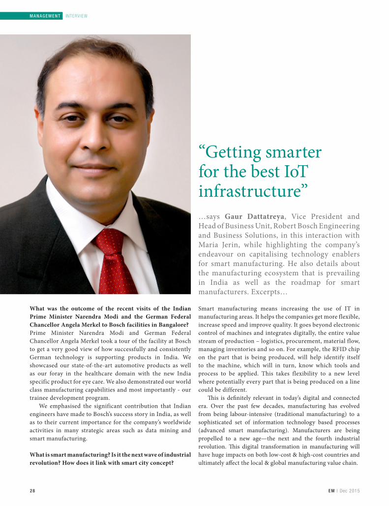
“Getting smarter for the best IoT infrastructure”…says Gaur Dattatreya, Vice President and Head of Business Unit, Robert Bosch Engineering and Business Solutions, in this interaction with Maria Jerin, while highlighting the company’s endeavour on capitalising technology enablers for smart manufacturing. He also details about the manufacturing ecosystem that is prevailing in India as well as the roadmap for smart manufacturers. Excerpts…
MANAGE ME N T | I N TERV I EW
What was the outcome of the recent visits of the Indian Prime Minister Narendra Modi and the German Federal Chancellor Angela Merkel to Bosch facilities in Bangalore?Prime Minister Narendra Modi and German Federal Chancellor Angela Merkel took a tour of the facility at Bosch to get a very good view of how successfully and consistently German technology is supporting products in India. We showcased our state-of-the-art automotive products as well as our foray in the healthcare domain with the new India specific product for eye care. We also demonstrated our world class manufacturing capabilities and most importantly - our trainee development program.
We emphasised the significant contribution that Indian engineers have made to Bosch’s success story in India, as well as to their current importance for the company’s worldwide activities in many strategic areas such as data mining and smart manufacturing.
What is smart manufacturing? Is it the next wave of industrial revolution? How does it link with smart city concept?
Smart manufacturing means increasing the use of IT in manufacturing areas. It helps the companies get more flexible, increase speed and improve quality. It goes beyond electronic control of machines and integrates digitally, the entire value stream of production – logistics, procurement, material flow, managing inventories and so on. For example, the RFID chip on the part that is being produced, will help identify itself to the machine, which will in turn, know which tools and process to be applied. This takes flexibility to a new level where potentially every part that is being produced on a line could be different.
�is is de�nitely relevant in today’s digital and connected era. Over the past few decades, manufacturing has evolved from being labour-intensive (traditional manufacturing) to a sophisticated set of information technology based processes (advanced smart manufacturing). Manufacturers are being propelled to a new age—the next and the fourth industrial revolution. �is digital transformation in manufacturing will have huge impacts on both low-cost & high-cost countries and ultimately a�ect the local & global manufacturing value chain.

29
I N TERV I EW | M ANAGEMENT
EM | D e c 2015
“One has to develop a holistic plan for systematic investment in upgradation of material and human resources”Gaur Dattatreya
According to you, what are the technology enablers for smart manufacturing? How Robert Bosch capitalises on such technologies as a strategic asset for growth?Industry 4.0 combined with traditional manufacturing along with IT and the Internet of Things (IoT) are the key enablers for the transformation in the manufacturing sector. Global companies are introducing pilot projects in India on Industry 4.0. Initial results show up to 30% productivity increase, significant cost reduction and reduction of stock. At Bosch in India, we are investing in all of our 14 manufacturing plants to make them smart manufacturing locations in a time bound fashion. Additionally, we are offering services to Indian industry to help them in their transformation towards smart manufacturing. Adaptation to latest IoT technology and upgrading our existing machinery is a continuous process for us striving to achieve the best results in the world. We want to set an example of the best IoT infrastructure in the country and continue to churn out leading quality products.
What do you think on the network of suppliers and vendors called as manufacturing ecosystem that is prevailing in India? Is the country ready to leverage smart manufacturing concept?All the technology pieces for smart manufacturing are available. Manufacturing ecosystem has to gear up and get into the digitally integrated environment. Each member of the ecosystem is required to develop their respective roadmap for transformation. The good news is that for integration you require additional joining pieces, you don’t have to throw away your existing lines.
How Robert Bosch is keeping up pace on skill development to act as a knowledge provider for next generation manufacturing? Skill development is an important part of the new system. When automation increases, we will require less number of people (but highly trained ones) to operate lines than we require now. At the same time, additional roles will emerge
that will require different skills. Skill development and retraining is a necessary part of smart manufacturing. It will not mean reduced number of jobs; on the contrary there will be more demand for skilled people.
At Bosch, we are devising and deploying programs to train our staff on the new requirements. This is also true for white collar jobs as well as leaders.
Your company recently announced ̀ 650 crore of investment in Indian operations to implement connected production in all 14 manufacturing plants across the country. Is it a part of your strategy to align your plans with “Make in India” initiative by the Govt of India?As a part of the ‘Make in India’ business initiative, the Indian government aims to advance industrialisation and modernise production in the country. Connected manufacturing offers great opportunities to faster react to market requirements, reduce manufacturing downtimes, improve efficiency of supply chains and increase productivity factors, which all can contribute to increase the competitiveness of the Indian industry over the long-term.
We are committed to the ‘Make in India’ campaign, hence, our focus is towards producing worldclass products using the best infrastructure, not only for consumption in India, but also for exports. The total investment that Bosch has made in our manufacturing plants spanning over more than 60 years will run in phenomenally large numbers which will surely humble the recent announcement of ` 650 crore.
Can you comment on the roadmap for smart manufacturers?Roadmap is required for every manufacturer to transform and become smart manufacturer. Depending on the state of current automation and the desired position, one has to develop a holistic plan for systematic investment in upgradation of material and human resources. If improving flexibility, speed, quality or productivity is on your agenda, start your transformational journey now. ☐

30 EM | D e c 2015
MEDIC AL MACH IN IN G | FOCUS
Vineet SethMD – India & Middle East,Delcam Ltd, [email protected]
Challenges in the healthcare industryHealthcare companies are under pressure to provide this higher quality at lower cost and to increase their productivity to meet the growing demand. In order to meet these requirements, it is important to use advanced CAD/CAM software and CNC machines for machining of medical devices.
As per a recent market report, India imports nearly 75% of all medical devices. The medical devices market in India, according to a leading analyst company, is over 3 billion US dollars annually, currently. This number will grow higher in the coming years. The reason for such massive imports is largely due to archaic standards, very little or no encouragement for indigenisation and improper application of said devices – to name a few. Adding to this, the comparative availability of trained professionals in the medical device domain – particularly in machining, to that of other engineering or medical fields adds to the challenges faced by the healthcare industry in our country. About 20% of these imported devices are made through direct high-end manufacturing / machining processes. This in itself is close to over 600 million US dollars a year.
Driving factors
Companies in the healthcare industry face the same demands from their patients that traditional engineering clients see from their customers for faster delivery of better and cheaper products. Patients want to receive higher quality products and services, and they want to complete their treatment in the shortest-possible time. At the same time, healthcare companies are under pressure to provide this higher quality at lower cost and to increase their productivity to meet the growing demand. These requirements can only be met through the application of more advanced and more automated technology. Multi-tasking machines are being used increasingly in the medical and dental industries, applications include the manufacture of all types of medical and dental

31EM | D e c 2015
FOCUS | M EDI CAL MACH IN ING
screw, prosthetics, and components for medical equipment.In order to drive these complex and multi-tasking
machines, it is always important to use a CAM software that complements these machines in every way. The primary reason for using advanced CAD/CAM software and CNC machines, is to reduce the overall time and cost for creating the medical component. The benefits of medical machining may offer opportunities for reduced waiting times for the patient, avoiding unnecessary surgery, compress process times, reduce patient trauma, speed up patient recovery time and finally reduce medical costs – both for individuals and insurance companies.
Design & manufacture
For example, Delcam’s healthcare solutions help design and manufacture custom-made maxillofacial implants for patients suffering with tumours or major bone loss. Typically, the reconstructive surgery carried out at the time involved a bone graft using a shaped portion of patient’s fibula. Aesthetic outcomes were often poor and the patient had to endure a lengthy period in a leg plaster cast while the fibula healed. Ideally, the surgeons would like to operate well beyond the margins of the tumour and insert the custom-made implant in the same procedure. Therefore, surgeons want implants to
be ready in time for the surgery and also that these implants are accurate in every aspect.
The process used by customer begins when patient data in either a CT or MRI scan is received. This data is converted into STL format to produce prototype models of the skull and the implant. This enables the operation procedure to be practised in advance and ensures that there are no surprises in the operating theatre. The same technology is also used to produce drilling jigs and/or cutting jigs needed by the surgeon. The next decision concerns the manufacturing method for the implant. The more straightforward examples can be machined directly from medical-grade titanium using five-axis machining; but the more complex implants require a combination of additive manufacturing and machining.
As far as bone screws and smaller dental implants are concerned, these are manufactured using a special type of machine called a Swiss-lathe. The Swiss-lathe is a multi-tasking machine that performs multiple operations simultaneously. Typically, the medical parts machined on Swiss-lathe are less than 25 mm in diameter. One can only imagine how critical and complicated it is to sequence the many moving parts and axes of a Swiss-type machine. Using a patented approach called divide-and-conquer, the programmer is able to view the part the same way the multi-axis lathe on which it is being machined sees it. The software
For specialist bone screws and smaller implants, it is very important to simulate machining beforehand

32 EM | D e c 2015
MEDIC AL MACH IN IN G | FOCUS
With a computer-generated simulation of the machining process, the user can see in exacting detail what the part will look like after it’s been programmed, no matter how small it is
does so by breaking down a part into a series of machining tasks for different part faces programmed in ‘Face Windows.’ It lets the user see a multi-axis turn-mill for what it really is, which is to say, not just a mill and a lathe, but really a lathe with up to nine different types of milling capabilities, depending on the capabilities of the machine and the engineering requirements of the part at hand. Thus, this approach lets a user quickly program a part in the exact way his machine will cut the component.
For specialist bone screws and smaller implants, it is very important to simulate machining beforehand. Often their critical features are not visible to the naked eye. However, the machines and tooling used to make these parts are huge by comparison. With a computer-generated simulation of the machining process, the user can see in exacting detail what the part will look like after it’s been programmed, no matter how small it is. In addition, with a full simulation of the machine tool itself, the user can see what, if any, machine collisions might occur during the manufacturing of a part.
Education & training
Although these technologies are available and can be employed on a full scale, they do require skilled manufacturing engineers to be employed in order to achieve the desired results. For example, machining expertise in an aerospace company – where he worked earlier, helped a Delcam customer in optimising medical machining. Many of the
materials used in medical machining are aerospace grades of aluminium and titanium that the engineer was familiar with from his earlier career and helped him reduce the machining time by half in a particularly important project.
It may not always be possible to invest in skilled manufacturing workforce. There are tools like the Delcam Custom Software Core, which is a library of middleware software that allows one to interface their .NET applications to PowerMILL (CAM) and PowerSHAPE (CAD) software. This allows development professionals to streamline processes in a user-friendly and intuitive way, so that many complex tasks of medical device designs and CNC programming are greatly simplified.
The custom solution, for example, can be used to automate the following -
CAD process (iterative design) Toolpath calculation Post-processing NC program transfer to the CNC Computer aided inspection process Report generation Archiving and retrieval
3D printing
An area of emerging interest is 3D printing, which essentially means that a component is built layer by layer, literally. A subset of additive manufacturing, 3D printing helps

33EM | D e c 2015
FOCUS | M EDI CAL MACH IN ING
save material wastage as the raw material is typically in powder form, fused by a variety of techniques – usually depending on the material and the 3D printing machine, to form the 3D part, which is input as a triangulated mesh CAD model. While 3D printing allows for complex shapes to be created that is otherwise not possible with subtractive machining, it is a much slower process and often quite expensive. Having said this, the cost of 3D printers are now coming down and there are also more material that are available for 3D printing.
3D printing is not limited to metal implants and generic medical devices alone. Even in the field of mass customisation, by combining the functionality of different software modules, Delcam has been able to generate and print a series of concept designs which demonstrate some of the possibilities for devices such as custom foot orthotics to be created by 3D printing. The process comprised of creating the orthotic designs where additional product features were added. These
included structural ribs for strength, high resolution 3D relief for aesthetics and textures/aeration holes for potential clinical benefits.
Additive manufactured custom orthotic insoles process does not replace the faster and more economical subtractive milling method but it does open some new and interesting doors. For example, by 3D printing an orthotic, the practitioner is able to design the ideal custom insole unhindered by the restrictions of conventional manufacturing. For the immediate and present future, it is best to combine the strengths of additive and subtractive manufacturing – where possible, to derive the best value out of the process.
With all of the above developments, manufacturers now have the opportunity to cater to any form of medical device or equipment manufacture without the need to change or switch between different CAD/CAM providers. This in itself will reduce half the complexities. ☐
Advt


36 EM | D e c 2015
SUPPLY CH A IN M AN AGE MENT | T E CH N OL OG Y
Lean guiding principles for the supply chain This article talks on Built-in Quality - one of the lean guiding principles, to develop a lean culture in a supply chain operation. With processes designed to make work flow correctly, and tools available to eliminate small problems before they grow large, employees can focus on delivering excellent products and services that increase overall customer satisfaction.
In the supply chain arena, a lean culture offers tremendous rewards, but pursuing a lean strategy also requires a significant commitment. Luckily, becoming lean doesn’t mean you have to re-engineer your operation. You can work with a logistics partner to make continuous, incremental gains in quality and efficiency.
Built-in Quality: Get it right the first time
High quality in the production and distribution of products improves your bottomline. If employees always know where to find the product they need, goods flow smoothly from one section of the facility to the next. Orders can be filled correctly, completely and on-time, satisfying customer demand. You save
time because there’s no need to correct mistakes, and you save money because your product is never damaged and retailers don’t experience stock-outs. Your efficiency often allows you to take advantage of lower-cost transportation options.
You can’t enjoy these advantages by inspecting for quality after the fact. The way to ensure quality is to perform work correctly the first time. That means building quality into every process.
Mistake-proofing to eliminate rework
A company should engineer its supply chain processes with its workers in mind. Any worker should be able to perform processes perfectly to meet the requirements of customers and

38 EM | D e c 2015
SUPPLY CH A IN M AN AGE M ENT | T E CH N OL OG Y
other stakeholders, such as regulatory agencies. Once the engineering team designs a process, they conduct a failure mode and effects analysis (FMEA)—a trial run in which someone tries on purpose to “break” the process. By locating weak points where mistakes might occur, the engineers are able to bring the process even closer to perfection.
Next, the design team decides which metrics it will use to determine whether the process is meeting its requirements. Then it documents the standards for performing the work. The team describes the process in text and also creates simple how-to instructions using photographs to illustrate each step for employees.
When a lean business opens a new supply chain facility, it follows the procedures described above to create and document each process that workers in the facility will perform. It then monitors work in the facility for 90 days to make sure that all the processes are working as expected. Once those processes are validated, the facility is certified to be fully operational. Over time, as customers’ needs change and the facility starts to handle different products, the engineering team creates, documents and certifies new processes, always aiming to ensure that anyone can perform the work without error.
In-process controls
Along with designing error-proof tasks, a company can implement safeguards that prevent mistakes while work is in process. Some of these in-process controls may be simple visual reminders. Technology also helps. For instance, an employee who is packing a box with ten items might use a scale to check the weight of that box. If each item weighs one pound, the employee cannot accidentally pack the box with eleven items. The ten-pound reading on the scale signals that the packing job is complete. This safeguard ensures that the employee sends only correctly-packed boxes to the next station.
Bar code scanning systems help to maintain quality at many points along the supply chain. In a warehouse, pickers working along a row will scan location codes to ensure that they are in the right aisle. When they start picking, they scan the locations where product is stored to confirm that they have arrived at
the right slots. The scanner display then tells the workers how many boxes to pick. As they carry out their instructions, they scan the labels on each box, and the system confirms that they have chosen the right products. These multiple checks help to ensure that pickers fill their orders correctly. Subsequent scans as boxes are loaded onto pallets or into a trailer further reinforce the quality chain.
Understanding root causes
Even the most carefully-crafted processes, and the most reliable in-process controls, won’t eliminate errors completely. When a mistake slips past the safeguards, you need to dig down to get at the root of the problem. The goal is to further mistake-proof the process by ensuring that the error never has a chance to recur.
Consider a series of orders that include a certain model of graphics cards for a desktop computer. Before these orders are loaded onto a truck, an audit finds that they all contain the wrong card. As soon as the auditor uncovers the mistake, it’s time to stop work and walk back through the process to discover what went wrong. It’s not enough to replace the wrong cards with the right ones for today’s shipment. The team needs to discover the cause of the error and correct it, so the process is performed perfectly in the future.
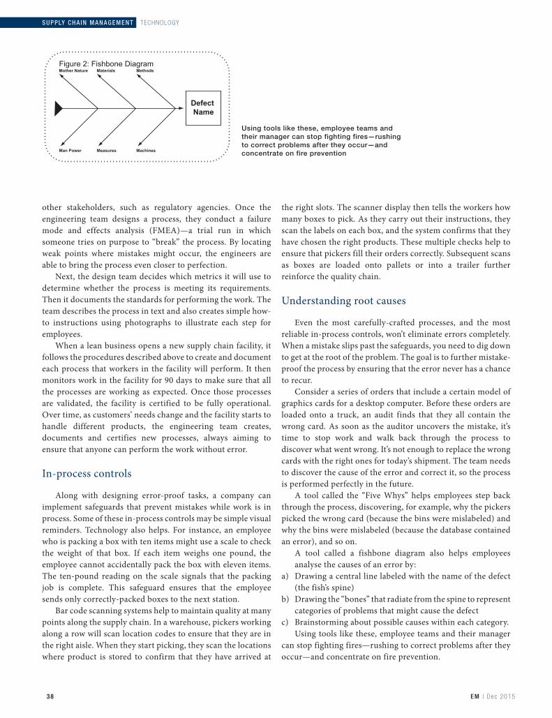
A tool called the “Five Whys” helps employees step back through the process, discovering, for example, why the pickers picked the wrong card (because the bins were mislabeled) and why the bins were mislabeled (because the database contained an error), and so on. A tool called a fishbone diagram also helps employees
analyse the causes of an error by:a) Drawing a central line labeled with the name of the defect
(the fish’s spine)b) Drawing the “bones” that radiate from the spine to represent
categories of problems that might cause the defectc) Brainstorming about possible causes within each category.
Using tools like these, employee teams and their manager can stop fighting fires—rushing to correct problems after they occur—and concentrate on fire prevention.
Using tools like these, employee teams and their manager can stop fighting fires—rushing to correct problems after they occur—and concentrate on fire prevention

40 EM | D e c 2015
SUPPLY CH A IN M AN AGE M ENT | T E CH N OL OG Y
Instant feedback
In the quest for quality, there’s no room for delay. You can’t wait for a Friday meeting to tell a supply chain team that in filling an order for side view mirrors on Monday, it shipped rear view mirrors instead. Workers will be hard-pressed to recall who picked that order, which aisles they worked, what instructions they received and what exactly they did.
Part of a team leader or supervisor’s responsibility is to help employees do their work according to established standards. When one of those leaders finds that a process is not working up to par, it presents an opportunity for coaching. The leader should take the employee aside immediately, explain what isn’t going right and provide instruction on how to do the work better. Leaders should also provide instant feedback when they observe employees performing their work remarkably well.
Get everyone involved
In a lean culture, it is every employee’s job to perform work according to the documented standards and to take
responsibility for quality control. A lean operation empowers employees to spot problems and fix them. But more than that, it empowers them to investigate why the problems occurred in the first place, in order to eliminate those ultimate causes and make sure the mistakes never happen again.
To transform employees into quality experts, it’s essential to eliminate fear from the equation. Employees should feel free to voice concerns, and to stop the flow of work to correct an error. When someone spots a mistake, that should never become an occasion for blame. The goal is not to point fingers, but to set things right so the team can continue to do the best job possible for its customers. Then the team should celebrate the improvement.
Conclusion
A lean culture builds quality into every facet of its operation. With processes designed to make work flow correctly, and tools available to eliminate small problems before they grow large, employees can focus on delivering excellent products and services that increase overall customer satisfaction. ☐Courtesy: Ryder Supply Chain Solutions
Lean Guiding Principles for the supply chain principle 2: Built-In Quality
Figure 1: Benefits of Built-In Quality

www.rollomaticsa.com [email protected]
High precision blank preparation, shank diameter up to Ø 20.0 mm, runout tolerance within 0.002 mm, and simultaneous grinding of roughing and fi nishing operations.Ground with the NEW ShapeSmart®NP3
The smart choice.

42 EM | D e c 2015
GEAR MAN UFACT UR IN G | T E CH N OL OG Y
Ready for large tasksWhere large powers and high torque are required, large gears are the answer: in marine drives, cement & coal mills, wind turbines & hydroelectric power plant. �e article talks on large industrial measuring centres for gears adapting to the current market needs.
In manufacturing, precise measurements are the cornerstone for complying with very tight tolerances and ensuring the efficiency of the entire operation. Large measuring centres have to be fast and easy to operate in order to determine the current quality of the workpiece and decide on any necessary corrections in the process chain.
The inner life of gear trains for wind turbines is especially quality-sensitive. These include cylindrical gears, cylindrical gear shafts, rings with internal gearings and planetary gears. Safe, reliable operation – even in heavy weather conditions – is absolutely essential, as the only way to safeguard a long and economic operating lifetime.
The increasing size of parts is leading to ever greater challenges for production quality. Customers or classification
societies need complete documentation, and this can be assured only by regular measurement and testing. The high requirements for process reliability and the associated quality documentation call for robust metrology near to the production line. Manufacturers of large gears consequently need high-precision measuring devices which can be operated as easily as possible.
The new ranges of model from Klingelnberg in the P series meet this need. The company now offers continuous measuring technology in the applications sector up to 3,800 mm. This satisfies maximum quality requirements and the standards of the classification societies. The new machine versions combine demanding geometry measuring tasks with high-precision gear measurement.
Dipl-Ing Günter MikoleizigProduct ManagementGear Inspection MachineryKlingelnberg [email protected]


44 EM | D e c 2015
GEAR MAN UFACT UR IN G | T E CH N OL OG Y
Shorter floor-to-floor measuring times
Measuring centres for large gears are suitable for measuring workpieces with an outside diameter up to 3,800 mm and a weight up to 20,000 kg. The machines have a rotary table and three linear measuring axes for acquiring measuring data. The new rotary table provides high running accuracy (radial and axial runout < 0.5 μm) – important prerequisites for accurate measurement of size, shape and position deviations during a single work cycle. A high-precision angle measuring system is integrated in the rotary table axis for rotational position acquisition. 3D stylus systems with digital data encoders are used for optimum measured data logging on the tooth flanks. The traversing paths of the linear axis allow inspection of up to 800 mm in the horizontal plane and vertical distances up to 2,000 mm. The rotary table and the linear measuring axes are powered directly by AC motors for greater guiding accuracy.
The rotary table and the linear axis measuring attachment are supported on a load-bearing machine bed. Combined with a suitable foundation, this provides a geometrically reliable base for the measuring machine. The machine design enables inspection of various diameters and distances on the same workpiece in one set-up. The gear measuring centres are optionally available with a straight horizontal measuring axis, including a 3D stylus system or a downward angled measuring arm. The horizontal axis is useful in versatile applications for disc-shaped workpieces and shafts and for gear-cutting tools. The angled variant is particularly suited for testing gears in planetary systems used in the wind power sector. Here the task of measurement is to test internal gears with large gear widths and to perform high-precision dimension, dimensional (MFL) measurements in workpiece
bores. The angled measuring arm can move the 3D stylus head inside the bore close to the measuring point, ensuring high measuring accuracy.
Special features are used to facilitate loading prior to a measurement. Shaft-type workpieces can optionally be clamped with a column and tailstock for a fixing range up to 2,500 mm, so that they can be fixed between centres. Disc-shaped workpieces are placed on the rotary table of the measuring machine. Depending on the size of the workpieces, extra fixtures are available for this purpose. To make an accurate measurement, the position of the workpiece axis is determined in relation to the rotary table axis.
Control feature
The control compensates deviations in a range up to 10 mm. This feature greatly simplifies loading of the measuring machine, as the operator no longer has the time consuming task of aligning the heavy workpieces with the rotary table axis. Centering elements together with an mm scale are quite sufficient. As an alternative, the measuring machines can be aligned mechanically via an air bearing integrated in the rotary table. This can be used to align even heavy workpieces exactly.
Using the control software, the operator can quickly create a measuring program to define the measurement sequence. He enters the test parameters together with the standards or directives for analysis. The desired and actual form can then be compared reliably using the analysis software. This is important, as large gears with high profile and tooth trace loads need especially large modifications. Measuring times are shortened by programming fixed measurement sequences, and the centre performs the prescribed steps iteratively.
Mounting table with support and centering element

FLEXIBLE SOLUTION» Easy integration into manufacturing systems
INTEGRATED AUTOMATION» Built-in pick-up spindle and conveyor belt
Precision Gear CuttingVLC 200 H VERTICAL PICK-UP HOBBING MACHINE
1 2 3
VERTICAL CHIP FLOW» Well suited for high-performance dry hobbing
FOR WORKPIECES
Ø 8 IN AND MODULE 4
EMAG India Private Limited “Technology Centre” I No. 17/G/46-3 · Industrial Suburb I 2nd Stage · Yeshwanthpur I Bangalore · 560022 I Karnataka · IndiaPhone: +91-80-42544400 I Fax: +91-80-42544440 I E-mail: [email protected] I Website: www.emag.com www.emag.com

46 EM | D e c 2015
GEAR MAN UFACT UR IN G | T E CH N OL OG Y
Versatile adaptability
In addition to the standard equipment, users can opt for additional features to customise a measuring centre. This enables them to respond specifically to a measuring situation. The resulting centering accuracy in the millimetre range is sufficient to start the measuring run immediately. Additional mounting tables with different diameters are available for large ring-shaped workpieces. These are designed to be changed with a short set-up time and effort. The fixtures used on the rotary table also fit the mounting tables.
Centres are preferred for fixing shaft-type workpieces. Tailstocks in different types are available. Detachable columns with a tailstock are used for small workpieces or gear-cutting tools. Fixed columns with tailstock are available for testing extremely long and large shafts, enabling measurements on up to 2,500 mm fixing lengths. The column can be moved using a wireless remote control to adjust the arm for the necessary fixing length or to adapt it for the loading position.
An optional automatic stylus changer speeds up the process if a number of different measurements are made in succession. The stylus is then changed automatically during the measuring sequence. Precision is maintained due to the high centering accuracy of the stylus holder plate. If the stylus still needs to be calibrated for certain measurements, this is done outside the centre of the machine. The operator sees the necessary instructions for a manual stylus change on the screen.
Measuring surface roughness
The P series machines also have an optional feature for measuring surface roughness on the tooth flanks. The
procedure is simple to adapt and functions on the skid plate principle. The parameters it provides a single run, together with other measurements, are the centre line average (Ra), the average peak-to-valley height (Rz) and the maximum peak-to-valley height (Rt). The special stylus system is changed either manually or automatically. Appropriate roughness sensing systems are available for the respective module sizes.
Precise results can be obtained only if the workpiece temperature at the time of measurement is taken into account. A difference of a few degrees Celsius from the reference temperature (20 °C) will cause results to deviate by two-figure micrometer amounts when determining test parameters for profile tooth traces and for the base tangent length. To avoid such inaccuracies, the new P machines provide an optional workpiece temperature sensor. This has to be placed manually on the workpiece prior to the measuring run. The temperature measurement takes only a few seconds. All subsequent measurements are then related to the reference temperature.
The angled measuring arm of the W version is fitted with a monitoring camera. The ultra-compact camera can be fixed flexibly on the measuring arm according to the intended measurement and the required viewing angle. Its primary task is to let the operator view the position of the stylus on the monitor of the control unit when measuring inside gear teeth, and make any necessary corrections.
Feedback from the industry is the basis for developing new gear testing machines and measuring concepts. The main focus is on key market requirements for faster processes with simultaneously high quality standards. The modular design enables to customise measuring devices for individual demand in the industry. ☐
Gear measuring centre P 150 W provides accurate and fast measurements of workpieces up to 1,500 mm diameter and a weight of up to 8,000 kilograms

47
ADVERTOR IAL | M ANUFACTUR ING I T
EM | D e c 2015
If productivity matters, choose ESPRIT CAM software
The medical industry now faces challenges met by some of the other industries in past: the need for sophisticated, robust computer-aided-manufacturing (CAM) software for complex machining. ESPRIT CAM software, by DP Technology Corp, is the choice of many medical-industry manufacturers like Stryker, Johnson & Johnson, Smith & Nephew Orthopedics, Orchid Orthopedics, Chetan Meditech, Meril Life & many more that seek to make high-quality, complex parts and cut programming time.
Performance enhancement is one of the major concerns in all these companies. Looking at the small sizes of variety of products it is very difficult for CAM software to provide accurate solution, automation options and reduce cycle time & programming time. With ESPRIT CAM software, the company provides training and support for its customers to improve their production line with a variety of automation options available inside the software. Any such complex operations like re-chucking, broaching, thread whirling, pinch turning/milling, support axis synchronisation, etc are easily supported inside the software.
As a worldwide leader in CAM innovation, it provides powerful solution to CNC programmers in all manufacturing disciplines. This high-performance CAM software is designed for ease of use and is compatible with all types of CNC machine tools. ESPRIT covers the spectrum of medical applications: 2-5 axis milling, 2-22 axis turning, 2-5 axis wire EDM, multitasking mill-turn machining and B-axis machine tools.Saves time: ESPRIT maximises the capabilities of mill-turn machine tools. The software’s functionality includes mill-turn on C and Y axes and it combines turning, milling and drilling operations in one G-code program. Users can perform accurate 5-axis milling machining, whether simultaneous or indexed, and fully exploit the power and flexibility of machines equipped with a B-axis. Accurate simulation: ESPRIT features solid and dynamic simulation that eliminates the risk of collision. Simulation
applies to the whole spectrum of cycles in mill-turn (2-5 axis) machining, as well as turning with multiple spindles and multiple turrets, up to 22 axes. The programmer verifies a listing combined with all milling and turning operations, plus associated cycle periods.
Certified post processors: ESPRIT CAM software for sliding head machines generates quality G-code programs for Swiss turning that are highly optimised to minimise cycle times, reduce remnant waste, and preserve tool wear while maximising part quality. It does not provide post processor; it provides machine drives which provides accurate G-codes for any machine with any controller. ☐
ADVERTORIAL
Stainless steel Harpoon® suture anchors produced in ESPRIT This screw, about 1.5 cm in length, has a tapered core and a triplethread with variable pitch. It was produced for orthopedic surgery
DP Technology has come up with one of the most revolutionary modules which is confined and specially customised for medical industry. This gives a chance to all the medical companies to make use of something which is specialised in their sector and kick-start its implementation from day one.
“The post processor’s accuracy and the training & support has been phenomenal”Chetan Meditech
“ESPRIT is one of the few software in the world, which can support any kind of machine with any controller”Orchid Orthopedics
Customers’ quotes

48 EM | D e c 2015
CUTT I N G TO O LS | T ECHNOL OG Y
Taking hole deburring to new depthsA read on how the new MEP (mechanised edge profiling) process developed by Seco Tools keeps exit burrs from negatively impacting tool rigidity, machining accuracy and tool life in deep, small-diameter through-holes
Burr formation creates challenges for part manufacturers across all industry segments, especially when drilling deep through-holes in critical components. In these applications, burrs of excess material form at both the entrance and exit of the workpiece, with the exit burr posing the most challenge. These burrs can lead to poor part quality and production inconsistencies, which are unacceptable in aerospace and other closely regulated industries.
Manufacturers traditionally remove burrs with hand grinders, emery cloth or other manual processes. These methods, however, are slow and require the part to be moved and refixured for the deburring process. Even when performed by skilled personnel, it is impossible to achieve part-to-part consistency in manual deburring operations. Mechanised Edge Profiling (MEP), on the other hand, employs an engineered tool, guided by a machine tool’s CAM program,
to remove burrs quickly and consistently. Hole edges can be finished to high-tolerance specifications on the same machine that drilled the hole initially.
Seco Tools has developed a new MEP process that combines innovative tool design with 5-axis toolpaths to enable fast, repeatable deburring of holes deeper than 10 times diameter.
End user demands
The aerospace industry specifies dimensions for certain part and hole edge conditions, including chamfer and radii. These features typically undergo approval and certification processes to meet tolerances measured in hundredths of a millimeter as well as ensure consistency from part to part. The deburring process has to achieve a precise balance
Teun van AstenEngineer, Marketing Services—Solid MillingSeco Tools

49EM | D e c 2015
TECHNOLOGY | CUTT ING TOOLS
between machining away the burr without removing material from the part.
Standard deburring and profiling tools used for MEP processing of part edges and other features include solid-carbide chamfering end mills as well as tools that employ indexing inserts with complex cutting geometries. Custom MEP tools have specific radii, chamfers, angles and combinations of those cutting edge features. The most sophisticated deburring tools have edge designs that produce a chamfer with a radiused edge preceded by lead-in and lead-out angles designed to prevent formation of secondary burrs.
MEP tools commonly have square cutting edges, but ball nose and lollipop-style tools are available for profiling edges on contoured components that would otherwise restrict access of square-edged tools. Applied on a 5-axis machine, a ball nose tool can scan the line of a complex part profile and create a radius on a long contoured edge.
Toolmakers also provide tools custom-engineered to profile edges and remove burrs at the entry or exit of larger through-holes. The custom tools feature complex cutting geometries. When cutting conditions are stable and cuts are smooth and uninterrupted, the tools permit use of more aggressive cutting parameters. Conversely, when features such as access holes interrupt the cutting path, parameters are more conservative to minimise tool wear and failure.
Deep, small-diameter holes
The exit ends of deep, small through-holes are challenging to deburr because they require small-diameter tools. As
hole depth grows, the tool’s length-to-diameter ratio also increases, making it less resistant to cutting forces and more prone to vibration, chipping or breakage. Moderation of the cutting parameters is necessary and deburring may not be fully effective.
Tool & process development
Seco has developed an innovative tool concept and combined it with 5-axis toolpath strategies that facilitate effective deburring of the exit area of deep, small-diameter through-holes. The tool features a tapered shank with a large neck diameter where the tool enters the part. The design provides a 0.05-mm clearance between the neck and diameter of the hole. Below the entry of the hole the tool tapers to a smaller diameter and at its end are cutting edges.
The CAM toolpaths employ 5-axis motion to tilt and rotate the workpiece so that the centreline of the tool circles around a point and describes a conical form at the hole exit, where the tool’s cutting edges remove the burr. At the same time, the neck of the tool at the hole entry effectively remains stationary and does not interfere with the sides of the hole. A Z-axis movement positions the tool in the hole and then the machine’s 5-axis capability combines X, Y, and Z motion to perform the deburring process.
Application & testing
The tools and toolpaths deburring the exit of a 3.2-mm diameter, 36-mm deep through-hole, were initially tested. The length-to-diameter ratio was greater than 10:1. Initial
As hole depth grows, the tool’s length-to-diameter ratio also increases, making
it less resistant to cutting forces and more prone to vibration

50 EM | D e c 2015
CUTT IN G TO O LS | T ECHNOL OG Y
trial-and-error testing arrived at an optimal rotation rate of 1,200 rpm, a speed that enabled the tool to complete 128 holes without replacement.
Deburring each hole required no more than three seconds, compared to manual deburring techniques that could require a full day or more to deburr an equivalent number of holes. Because the CAM program and machine control handled the tool’s movement, the deburring results matched exactly from the first hole to the very last.
Programming details
To programme tool movement before the MEP process, the machine operator must enter the exact location and definition of the surfaces to be deburred. The tool length must be defined as well. Tools are ground to a tolerance within 0.0375 mm. The front end of the tool is ground in the same operation as the cutting edges, producing a relationship between the tip of the tool and the cutting edge within 0.0125 mm. The tool length is specified in the CAM program; the operator can confirm the tool length off the machine with a presetter or on the machine via a laser or touch probe.
MEP for multitasking?
Some MEP tooling combines the machining of a part feature with a deburring operation. Select end mills, for example, locate the MEP machining feature at the top of its cutting zone to machine the hole diameter and then deburr the entry point in the same operation.
Analyses of MEP applications have indicated that tools
engineered to remove burrs at the entry of a through-hole provide longer tool life than those designed for eliminating burrs at the exit end. Tools for deep-hole exit burrs have a higher length-to-diameter ratio, making them more prone to instability and vibration that, in turn, accelerate wear. Therefore, a tool engineered to deburr both the entry and exit of a deep through-hole would exhibit longer life for the entry feature than for the exit feature, resulting in the need to discard the tool with much of its capability unused.
Additionally, MEP tools that deburr the entry area of a hole can be reground, but the critical relationship between the cutting edge and tool tip in MEP tools for deep, small-diameter through-hole deburring precludes regrinding. The reason is that applying a reground tool would involve changing the offset in the machining program, something prohibited by the strict protocols of aerospace machining practices.
Conclusion
Manufacturers continually respond to customer demands for increasingly tight part tolerances. The aerospace industry leads the trend, but requirements for precision and consistency are becoming stricter in the medical, energy and other industries as well.
Deburring, an essential element of precision part production has long been carried out through manual methods. Unfortunately, these operations can be inconsistent from part to part and are expensive in terms of labour, setup and part handling expense. In fact, some end-users have banned manual deburring because it cannot be documented and certified. ☐
The tools and toolpaths deburring the exit of a 3.2-mm diameter, 36-mm deep through-hole, were initially tested

Factory Automation Technology CO.,LTDFar East Machinery Co.,Ltd
TEL:886-5-2205295 FAX:886-5-2205293 E-mail:[email protected]
FEMCO INDIA
Global Raisoni Ind Park, Gat No. 182/183/184 Part, Near Lonikand,Phulgaon, Alandi-Markal Rd,Pune 412216+91-20-66787600
Since1949
www.femco.com.tw
Production management
Tool management
On-line measuring
Monitorsystem
On-liililinline MonitorolTooProPP duction
Horizontal Lathe series
Multi-Axis Machineseries
Wheel Turning Latheseries
Vertical Latheseries
Horizontal Boring & Milling machine series
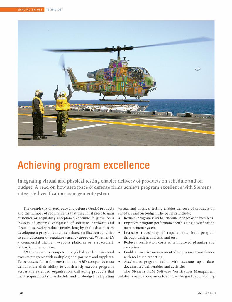
52 EM | D e c 2015
MANUFACT UR IN G I T | T EC H N OL OG Y
Achieving program excellence Integrating virtual and physical testing enables delivery of products on schedule and on budget. A read on how aerospace & defense firms achieve program excellence with Siemens integrated verification management system
The complexity of aerospace and defense (A&D) products and the number of requirements that they must meet to gain customer or regulatory acceptance continue to grow. As a “system of systems” comprised of software, hardware and electronics, A&D products involve lengthy, multi-disciplinary development programs and interrelated verification activities to gain customer or regulatory agency approval. Whether it’s a commercial airliner, weapons platform or a spacecraft, failure is not an option.
A&D companies compete in a global market place and execute programs with multiple global partners and suppliers. To be successful in this environment, A&D companies must demonstrate their ability to consistently execute programs across the extended organisation, delivering products that meet requirements on-schedule and on-budget. Integrating
virtual and physical testing enables delivery of products on schedule and on budget. The benefits include:
Reduces program risks to schedule, budget & deliverables Improves program performance with a single verification
management system Increases traceability of requirements from program
through design, analysis, and test Reduces verification costs with improved planning and
execution Enables proactive management of requirement compliance
with real-time reporting Accelerates program audits with accurate, up-to-date,
documented deliverables and activities The Siemens PLM Software Verification Management
solution enables companies to achieve this goal by connecting
53EM | D e c 2015
TECHNOLOGY | M ANUFACTUR ING I T
requirements to all tasks, analyses, tests and data involved in the verification process, providing complete visibility and traceability across planning, design, analysis, test and final conformance reporting.
Providing full lifecycle traceability
Programs must meet requirements that are set by their customers, contained in their contracts, and meet company product standards for design and safety, as well as industry requirements from regulatory authorities such as the Federal Aviation Administration (FAA) and the European Aviation Safety Agency (EASA). Teamcenter software from Siemens PLM Software enables all program activities to be driven by these requirements, from initial program goals to the individual components that will make up the final product. With Teamcenter, full product lifecycle traceability makes it possible to ensure that all requirements have an approved verification method, that the method is executed, and that appropriate results are recorded to support achievement of the requirements.
Synchronising analysis from design through test
As a full product lifecycle solution, Teamcenter can be used to communicate requirements to all disciplines in the product development process as well as changes to those requirements. This single collaborative source permits design, analysis, and test organisations to work in unison to ensure that analysis and simulation models are synchronised with design models for both production and test articles, and that physical test articles conform to requirements across disciplines. By synchronising these models, simulations representing the production design - as well as all the modifications made to the test article - remain valid for
proving requirements are met. Teamcenter also provides integration of analysis-to-analysis (an often-overlooked failure point) by managing the process to take the outputs from one analysis and them as inputs to the next analysis, as well as all the other artifacts required to conduct the next analysis; other boundary conditions or inputs, models, etc. Only in this way are design analyses and tests truly integrated and connected.
Tracing the test to the physical test article
Physical tests are a necessity for aerospace and defense products, and it’s imperative that tests prove that requirements are met. Proving a test valid requires that a sequence be followed from requirements to be verified to test plans that define the verification approach and that test articles and equipment are configured properly. Teamcenter establishes the path from requirements to test plans to test article to confirm that a test is required, properly planned, and accurately executed. If changes in requirements or the product design occur, Teamcenter can be used to immediately provide full visibility of their impact on plans, test articles, and tests including those already run that need to be re-executed.
Teamcenter also maintains the complete history of all test articles and equipment, enabling full traceability to the past test article or analytical model configurations. In addition, Teamcenter provides complete instrumentation traceability: from measurement requirements defined by engineering in the test request; to the instrumentation plan; to the physical instrument installed on the test article and its calibration data through to the raw data and the reduced engineering unit data used for reporting compliance. Full traceability enables the ability to demonstrate that the test article matches the current engineering definition as well as the original production design at every stage.

54 EM | D e c 2015
MANUFACT UR IN G I T | T ECH N OL OG Y
Integrating verification management system
Moving from planning what to do to actually doing it requires task definitions, scheduling, and management. Teamcenter provides this functionality for all verification activities to link engineering, manufacturing, procurement, and test to support long lead planning, resource utilisation and execution of the verification activities. Verification requirements are linked to supporting documentation for virtual and physical test configurations, test plans, test procedures and test results to enable complete status reporting of the process. This holistic approach ensures efficient usage of resources and provides visibility into the process to ensure that deadlines are met. Requirements can be linked to activities on the verification management schedule as well as to a Work Breakdown Structure for correlation to financial reporting systems; integrating cost, schedule, and technical requirements in a single system.
Additionally, the verification management solution includes a catalyst. This fast track implementation provides best practice models and preconfigured elements for activities such as defining data objects and roles that can be used in automated workflows. The open and configurable software allows you to control the appearance and behaviour of the Siemens PLM implementation, whether it is for a comprehensive PLM environment or a standalone verification environment. Deployment accelerators include recommended product selections, network design decisions, configuration procedures, deployment best practices and user training. The verification management catalyst enables you to accelerate the digital transformation of your enterprise. This allows you to improve productivity and achieve greater availability and reliability while reducing the total ownership cost.
Conclusion
The Verification Management solution in Teamcenter empowers A&D companies to successfully execute their programs on-schedule and on-budget by providing visibility and closed-loop requirement traceability into all activities of the verification process to confirm requirement compliance. With efficient planning, simulation, analysis and test execution in an integrated environment enabling confirmation of requirements achievement, Teamcenter supports program audits and reduces the time and cost of verification that ultimately improves program performance.
A simple idea inspired this product. Thousands of decisions made it real. Making a great product takes more than inspiration. It takes thousands of decisions for a good idea to become real. Not just the big milestone decisions, but all the small decisions that lead up to them. The fact is anyone can make the decision that makes the difference in your product’s success. For leading companies throughout the world, Siemens PLM Software is an essential environment for immersive product decision-making. The solutions give everyone involved in making your products “high-definition PLM.” HD-PLM ensures that people get the information they need, when they need it—with absolute clarity—to make more informed decisions faster. No matter what industry you’re in—automotive or aerospace, electronics or energy, marine or medical, machinery and more—PLM software helps you make the smart decisions that go into making great products. ☐Courtesy: Siemens PLM Software
Physical tests are a necessity for aerospace and defense products, and it’s imperative that tests prove that requirements are met

Projekt1 09.09.14 08:41 Seite 1
Toll Free: 1800 233 2065

56 EM | D e c 2015
EVENT | R EP ORT
With the recent visit of the German Chancellor Angela Merkel, both Germany and India have stepped up their bilateral cooperation and agreed upon 18 MOU’s. Today, the world is looking at India as the final destination for investments and growth and Hon’ble Prime Minister has set clear goals and reforms to help achieve them. The objective of these engagements are to support and augment the ‘Make in India’ programme through increasing the innovation and technology prowess of the Indian industry.
Highlights
The summit started with a welcome note from Rajesh Nath, Managing Director, VDMA India, where he mentioned that the Prime Ministers clarion call to ‘Make in India’ holds enormous promise to transform the Indian economy.
“Complemented by initiatives such as “Skill India”, Digital
India, Schwach Bharat and Sagar Mala, a foundation is being laid for a multiplier impact on inclusive development. This has emphasised on the 4 Ds - demographic dividend, democracy, demand and the recently added 4th D - deregulation. This effort shows to be bearing fruit as India saw the highest foreign direct investment inflow for new projects among all nations in the first half of 2015, beating America and China.” He further adds that in January-June 2015, India attracted $31 billion (` 2.05 lakh crore) in capital expenditure (capex) from foreign companies, China, the largest economy in Asia, attracted $28 bn and the US got $27 bn in the period.
Dr Corinna Fricke, Head Economic Section, Federal Republic of Germany in New Delhi reiterated the strengthening bonds between India and Germany and the increased bilateral trade between the 2 countries which crossed 17 Billion Euros in 2012. Dr. “There is immense potential for growth in the country but feels that it has been
Strengthening Indo-German relationsWith a participation of around 140 members, �e 4th VDMA Mechanical Engineering Summit was recently held at New Delhi. �e summit witnessed co-operation from German companies towards ‘Make in India’ campaign, and bestowed their support towards India’s future growth. A post-event report…

THE TG165 SHOWS WHAT’S HOT FOR INSTANT TROUBLESHOOTING.
The FLIR TG165 Spot Thermal Camera bridges the gap between single spot infrared thermometers and FLIR’s legendary thermal cameras.
Check out the interactive simulator to experience this groundbreaking tool in action. www.flir.com.hk/TG165
24:1 SPOT SIZE RATIO
Stay SafeVISUALLY KNOW WHERE TO TARGET
Speed & AccuracyDESIGNED TO WITHSTAND THE
HARSHEST ENVIRONMENTS
Rugged & Reliable
For further information, please contact us at:
FLIR Systems India Pvt. Ltd.1111, D Mall, Netaji Subhash Place, Pitampura, New Delhi – 110034Tel: +91-11-4560 3555 Fax: +91-11-4721 2006 E mail: [email protected]: www.flir.com
Images used for illustrative purposes only.
POWERFUL THERMAL IMAGING RIGHT IN YOUR POCKET
OVERLOADED DIMMER OVERHEATED PANEL RADIENT FLOOR HEATELECTRICAL HOTSPOT
FLIR C2 UNCOVERS HIDDEN ELECTRICAL & BUILDING PROBLEMS SO YOU DON’T MISS A THING.
The C2 is the world’s first full-featured, compact thermal camera you can always keep on you, ready to find troublesome heat patterns.
See what C2 can show you at www.flir.com.hk/c2
TG 165 and C2 AD.indd 1 30/11/15 6:46 pm

58 EM | D e c 2015
EVENT | R EP ORT
at a growing slowly but steadily specially in the last few months,” she said.
This was followed by an address by Dr Rajan Katoch, Secretary, Department of Heavy Industry, GOI. He enlightened the audience on “Manufacturing in India – Road to Progress”, where he explained the slew of measures taken by his department as part of the ‘Make in India’ programme to increase country’s share of manufacturing in GDP to 25% by 2020 from present 15%.”
Showcasing Indian relations
Ulrich Ackermann, Managing Director, Foreign Trade Division within VDMA Frankfurt shared insights of the German engineering industry, which attained a turnover in 2014 of 212 bn Euro, out of which the export share stood at 77% with Asia contributing to 27% of this export share. “India is the 5th most important country for German Machinery exports, while the top three include USA followed by Italy and Mexico. While India on the other hand, imported machinery from China followed by Germany and Japan,” he said.
The keynote address on “Overview of the Indian Economy” was presented by Arun Maira, Former Member, Planning Commission. This was followed by a presentation on “Goods and Services Tax- Impact on Manufacturing Industry” by Sandeep Gupta, Partner, ASA & Associates LLP, spoke on
“Goods and Services Tax- Impact on Manufacturing Industry”, where he presented various tax models implemented in developed countries and reiterated that Dual GST is to replace different indirect taxes on goods and services by the central & state governments.
Next, Ajay Shankar, Chairman & Expert Committee, Regulatory Approval, organised a session on “Ease of doing business – approach from Indian government”, where he touched upon various issues like creating regulatory layovers,
implementation of GST, Digital India and third party certification issues.
The second leg of the technical session began with “Prospects for Indo-German collaboration in high technology manufacturing” by Hermann Muehleck, Head—German Business Centre, India, Ernst & Young GmbH. The objective of the study was to identify high-technology sectors that are most suitable for Indo-German collaboration.
The session continued with “Application of Industry 4.0 in manufacturing” presented by Volker Schmid, Head—Asia Pacific, Festo Didactic SE. The concept was to inform & prepare for manufacturing of tomorrow, which is presently led by primarily Europe and other developed countries.
“Gaining importance in high-tech manufacturing, process automation and end-to-end digitisation of business will become a key driver for enhancing production and cost efficiencies. The Indian IT sector holds strong know-how on software development and on digitisation of business processes from which collaboration partners can benefit,” he explained.
The technical session ended with the insights on “Make in India Mittelstand” by Satish Sharma, Deputy Secretary (EW), Ministry of External Affairs. It is a first of its kind business support programme designed to offer services in coordination with the Indian Government and other entities. It starts with the company selection and on-boarding; in the second stage market entry support will be facilitated. Also, a panel discussion was held on “Make in India—a slogan or reality” moderated by Nath. The panelists highlighted the German dual system of education, which provides theoretical & practical knowledge to students. The students here are given an opportunity to not just learn, but also work in the industry, thereby, creating technically skilled workforce from the onset.☐Courtesy: VDMA
Rajesh Nath, MD,VDMA India; Arun Maira, Former
Member, Planning Commission; Dr Rajan Katoch,
Secretary, Department of Heavy Industry, GOI; Dr
Corinna Fricke, Head Economic Section, Federal
Republic of Germany in New Delhi; Ulrich Ackermann,
MD, Foreign Trade Division within VDMA Frankfurt
during the summit


60 EM | D e c 2015
EVENT | R EP ORT
There was a time when constraints of traditional 3D modeling were difficult to address to. However, things have changed now and with the latest version of Solid Edge—ST8, one can leave behind these complexities. ST8 has more flexibility built in its system, and, as such, is more effective. So much so, that people can come across their mother system and be able to be productive right away. It is also synchronous
& innovative, and helps to bring products faster in the market at a lesser cost.
Highlights
Day 1 of the event started with a welcome note by John Miller, Senior Vice President & General Manager, Mainstream
Designing without boundaries…Siemens PLM Software’s recently concluded Solid Edge University 2015 at Cincinnati, Ohio, USA, with the introduction of ST8 that delivers powerful modeling with unparalleled mobile flexibility & real-time access to vibrant global user community. The two-day event witnessed several general and breakout sessions, which helped users improve productivity, expand skills and experience the smart operation platform. A post-event report…
Megha Roy Features [email protected]
Imag
e co
urt
esy:
Sie
men
s PLM
Sof
twar
e
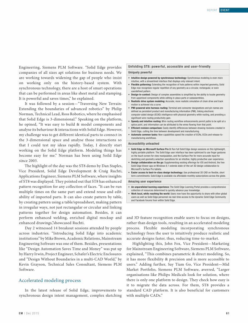
61EM | D e c 2015
REPORT | EVENT
Engineering, Siemens PLM Software. “Solid Edge provides companies of all sizes apt solutions for business needs. We are working towards widening the gap of people who insist on working only on the history-based system. With synchronous technology, there are a host of smart operations that can be performed in areas like sheet metal and stamping. It is powerful and saves times,” he explained.
It was followed by a session—“Traversing New Terrain: Extending the boundaries of advanced robotics” by Philip Norman, Technical Lead, Ross Robotics, where he emphasised that Solid Edge is 3-dimensional.” Speaking on the platform, he opined, “It was easy to build & model components and analyse its behaviour & interactions with Solid Edge. However, my challenge was to get different identical parts to connect in the 3-dimensional space and analyse those interactions so that I could test my ideas rapidly. Today, I directly start working on the Solid Edge platform. Modeling things has become easy for me.” Norman has been using Soild Edge since 2003.
The highlight of the day was the ST8 demo by Dan Staples, Vice President, Solid Edge Development & Craig Ruchti, Applications Engineer, Siemens PLM Software, where insights of ST8 was displayed. They pointed out that ST8 has enhanced pattern recognition for any collection of faces. “It can be run multiple times on the same part and extend reuse and edit-ability of imported parts. It can also create pattern by table, by creating pattern using a table/spreadsheet, making pattern in irregular ways, not just rectangular or circular and linking patterns together for design automation. Besides, it can perform enhanced welding, enriched digital mockup and enhanced drawings,”showcased Ruchti.
Day 2 witnessed 14 breakout sessions attended by people across industries. “Introducing Solid Edge into academic institutions” by Mike Brown, Academic Relations, Mainstream Engineering Software was one of them. Besides, presentations like “Design Automation Saves Time and Money” was put up by Harry Irwin, Project Engineer, Schafer’s Electric Enclosures and “Design Without Boundaries in a multi-CAD World,” by Kevin Grayson, Technical Sales Consultant, Siemens PLM Software.
Accelerated modeling process
In the latest release of Solid Edge, improvements to synchronous design intent management, complex sketching
and 3D feature recognition enable users to focus on designs, rather than design tools, resulting in an accelerated modeling process. Flexible modeling incorporating synchronous technology frees the user to intuitively produce realistic and accurate designs faster, thus, reducing time-to-market.
Highlighting this, John Fox, Vice President—Marketing for Mainstream Engineering Software, Siemens PLM Software, explained, “This combines parametric & direct modeling. So, it has more flexibility & precision and is more accessible to users.” Adding further, Say Tiam Go, Vice President—Mid Market Portfolio, Siemens PLM Software, averred, “Larger organisations like Philips Medicals look for solution, where there is only one platform to design. They check how easy is it to migrate the data across. For them, ST8 provides a standard CAD platform. It is also beneficial for customers with multiple CADs.”
Unfolding ST8: powerful, accessible and user-friendly
Uniquely powerful
Intuitive design powered by synchronous technology:
Flexible patterning:
Design-in-context:
Realistic drive system modeling:
PMI-powered wire harness routing:
Speedy and intuitive routing:
Efficient revision comparison:
Automate common tasks:
Accessibility unleashed
Solid Edge on Microsoft Surface Pro 3:
Design collaboration on the go:
Easier access to best-in-class design technology:
Amazing user experience
An unparalleled learning experience:
Work local, while reaching the world:

62 EM | D e c 2015
EVENT | R EP ORT
The full version of Solid Edge ST8 can be installed on tablets running Microsoft’s Windows® 8.1 operating system, giving users more freedom to design anytime, anywhere.
Speaking on the product development strategies, Staples shared, “We have a product planning & development team of around 15 people, which includes mechanical engineers, psychologists and graphic artists. They take care of the product development from the core. These strategies are based on themes like taking synchronous to new level, encouraging drafting, especially for sheet metals & creating a comfortable platform for people coming from other systems like SolidWorks.”
Simplifying 3D modeling
Simplification of large and complex assembly capabilities in Solid Edge ST8, combined with its ability to accurately simulate and predict kinematic conditions, greatly accelerates the assembly design process and significantly reduces the need for physical prototypes. Also, it offers multi-CAD designs that design faster and intelligently without the constraints of traditional 3D modeling. As per Fox, “ST8 enhances speed. It helps design from concept to market. Today, it is important to have global supply chains, where one needs to work with more suppliers. One can import disparate types of CAD technologies with synchronous technology. It’s good in interpreting files & reading them, not as dumb solids, but as actual models that you can manipulate with.”
A way forward…
Discussing the vision of Solid Edge for next decade, Staples highlighted that as the industry changes rapidly, we have to be flexible to change with it. “There are many developments happening in areas of cloud and Additive Manufacturing today. For defining our vision, we start from the core basis, i.e. being in sync with mechanical engineers and designers. Synchronous technology came to the picture only when we were done with CAD. However, drawings are still important. Also, sheet metal will get deeper with time. We will respond to Additive Manufacturing and cloud in a customer-oriented way. CAD is ultimately about the productivity at engineer’s desktop,” he concluded.
While wrapping up the two-day event, a sneek peek on ST9 was presented, which displayed that the next version will have customisation & preference management and support for high resolution monitors in which Solid Edge UI will
scale naturally with display resolution & have an easy access to Solid Edge UI. For part modeling, it will modify multiple bodies using a single feature and have solid sweep, which can sweep a solid along a path to generate cutouts or protrusions. In addition, for sheet metal modeling, a sheet metal clash in flat will be available to warn when plates clash in flat pattern. There will also be a Teamcenter tab on CommandRibbon to provide direct & easy access to commands and enhance learning experience of users.
“We have design centres in Pune, which are responsible for our products. There is a vast growth in manufacturing & designing capabilities in India”John Miller, Senior Vice President, Mainstream Engineering Software, Siemens PLM Software
“Our product development strategies are based on themes like how to take synchronous to new level, encouraging drafting, especially for sheet metals & creating a comfortable platform for people coming from other systems like SolidWorks”Dan Staples, Director, Solid Edge Product Development, Siemens PLM Software
“One can import disparate types of CAD files with synchronous technology. It’s good in interpreting files and reading them, not as dumb solids, but as actual models that you can manipulate with”John Fox, Vice President—Marketing for Mainstream Engineering Software, Siemens PLM Software
“The Indian market has a large workforce population. So, the professionals can learn the technologies much faster. Platforms like ST8 will not only enhance their learning process, but will make things smarter for the Indian market”Say Tiam Go, Vice President—Mid Market Portfolio, Siemens PLM Software
“With Solid Edge, it is easy to build & model components and analyse its behaviour and interactions. Today, I directly start working on the Solid Edge platform. Modeling things has become easy,”Philip Norman, CEO, Ross Robotics

63EM | D e c 2015
REPORT | EVENTREPORT | EVENT
Using Solid Edge from Siemens PLM Software has paved the way for many start-ups across the globe. The case study discusses how Ross Robotics has re-invented the way specialised service robots are designed, developed and used.
Revamping robotic dynamics
Powered by new technology, robots are becoming cheaper, smarter and more autonomous. As a result, more robots are being deployed beyond the automotive factory floor, in diverse market segments like defense, agriculture and logistics. These so-called service robots, often used to tackle dull, dirty, or dangerous jobs, comprise one of the fastest growing segments of the robotics industry. The International Federation of Robotics reports that technology-driven start-ups are stepping up to meet the growing demand, representing 15% of the companies in this segment.
Configuring robots faster
Philip Norman, CEO, Ross Robotics, has developed what he calls the world’s first and only modular robotic system – a platform that enables companies to configure application specific robots faster and more efficiently than traditional approaches. Ross Robotics’ platform includes numerous patented design elements. One is a coaxial physical/power/data connector – just plug and twist to connect both power and data stream. Another involves bio-mimetic traction devices that enable robots to scramble through dense brambles, up and down stairs and even swim. Philip sees potential for their application in relief work, in the oil & gas industry or in security, among other sectors.
One of Philip’s robots, heavily modified, is operating at the largest particle physics laboratory in the world for the European Organisation for Nuclear Research, known as CERN. “The
Large Hadron Collider, just outside Geneva has a very large amount of sophisticated equipment that needs to be monitored & maintained by robots, rather than people. Our robot system is largely non-metallic & non-magnetic as it is built using a hybrid plastic, non-magnetic metallisation process and can operate in extremely harsh conditions in the Collider,” explains Philip.
Speaking further on his robots, he says, “One of our robots has performed remote monitoring in the CMS experiment – this is the experiment that captured the Higgs Boson equipped with cameras, LiDAR scanners and a number of other specialised sensors. The robot is now autonomous and can, therefore, operate without requiring a human controller.”
Towards advanced technology
In the early days of his business, Philip designed with pen and paper, but, now, is a daily user of Siemens Solid Edge software. He understands the critical role that affordable engineering software has played in the success of his venture helping him design products as well as communicate complex ideas to customers. “We use Solid Edge as a rapid development tool to design the visuals and produce the real devices we deliver to customers,” he shares. He also recognises the unique advantages provided by Solid Edge’s synchronous technology, which he describes as “a curious combination of extreme accuracy and extreme fluidity.” ☐Courtesy: Siemens PLM Software
63EM | D e c 2015
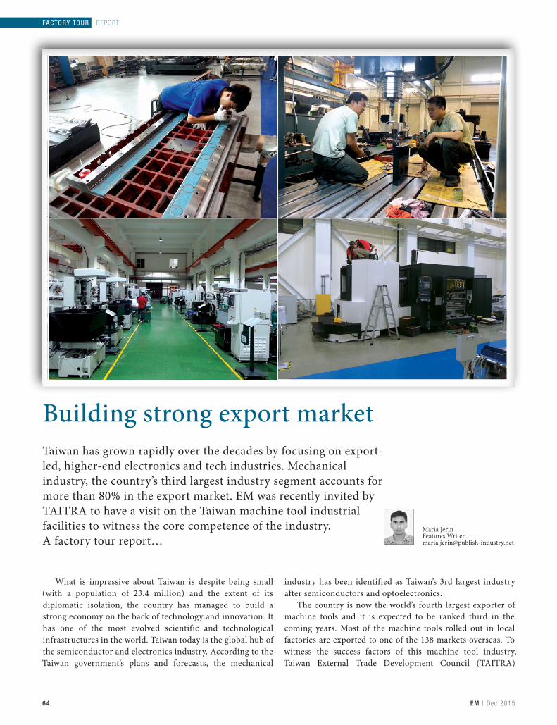
64 EM | D e c 2015
FACTO RY TOUR | R EP ORT
What is impressive about Taiwan is despite being small (with a population of 23.4 million) and the extent of its diplomatic isolation, the country has managed to build a strong economy on the back of technology and innovation. It has one of the most evolved scientific and technological infrastructures in the world. Taiwan today is the global hub of the semiconductor and electronics industry. According to the Taiwan government’s plans and forecasts, the mechanical
industry has been identified as Taiwan’s 3rd largest industry after semiconductors and optoelectronics.
The country is now the world’s fourth largest exporter of machine tools and it is expected to be ranked third in the coming years. Most of the machine tools rolled out in local factories are exported to one of the 138 markets overseas. To witness the success factors of this machine tool industry, Taiwan External Trade Development Council (TAITRA)
Building strong export marketTaiwan has grown rapidly over the decades by focusing on export-led, higher-end electronics and tech industries. Mechanical industry, the country’s third largest industry segment accounts for more than 80% in the export market. EM was recently invited by TAITRA to have a visit on the Taiwan machine tool industrial facilities to witness the core competence of the industry. A factory tour report…
Maria JerinFeatures [email protected]

65EM | D e c 2015
REPORT | FACTORY TOUR
recently organised a week-long factory tour to explore the country’s world-class industry cluster, very well linked supply chain, the industry’s stable quality, fast lead time and reasonable price. The visit included eight companies, who are specialised in different product categories: SHIEH YIH Machinery (SEYI), producers of mechanical presses; Taiwan Asahi Diamond Industrial, manufacturing diamond tools; Kao Fong Machinery (KAFO), specialising in manufacturing various ranges of machining centres, gun drilling machine, moving column type; Goodway Machine Corp, specialising in manufacturing various ranges of turning centres; Manford Machinery, specialising in manufacturing wide range of machining centres, CNC lathes, tapping centre; Accutex Technologies, producing cutting edge techniques in CNC wire cut EDM; Quaser Machine Tools that include various ranges of machining centres, five-axes machining, ATC tool management system, FMC series; KAO MING Machinery, specialising in a wide range of machining centres and radial drills.
Exploring machininig dynamics
The ability of Taiwan machine tools to compete with other countries without the support of a strong car industry or huge domestic demand depends entirely on Taiwan’s flexibility and adaptability. Taiwan’s machine tool industry supply chain, from R&D design to component manufacturing, assembly, testing and marketing, forms a complete system, thus, giving the industry an advantage. The shop floors are clean and well maintained with skilled technicians and contract labourers. Most of the critical machining components are machined by Japanese machines. “The mother machines are mainly from Japan that includes Mitsubishi, Mazak, etc,” said Jason Yu, Senior Sales, Operation Director, KAFO.
The core components of the machine such as spindle, machine bed and bearings are assembled with high level of precision and accuracy. Pointing out this, Rock Liao, President, Quaser Machine Tools, said, “All core components are precisely assembled in a constant temperature controlled room, which possesses higher assembly quality and technology integration of machines than general competitors in the market.” During the whole assembly, every contacting
surface is precision hand scraped to increase the flatness and improve geometric accuracy. “The factory floor is incorporated with skilled engineers for scrapping to make accuracy in the component. The hand-scraping process is labour-intensive and must be performed by skilled craftsman who are trained in the technique,” noted Irene Mao, Sales Dept, Section Manager, KAO MING Machinery Industrial. Further highlighting the challenges on this, Raoul Su, Sales Manager, Manford Machinery, noted that too much effort is needed to draw skilled people into their industry as the manufacturing industry is losing its charm.
Enabling business competence
Apart from the shopfloor factors, the companies have different product strategies that enable them to have business advantage. For example, SEYI’s product strategy includes servo technology, total solution application (Turnkey) and application of Industry 4.0. Goodway Machine has the business advantage of self-owned key component manufacturing. Talking on her company’s core technology; Rebecca Hsieh, Vice President, Sales Dept, Goodway Machine Corp, said, “Our product focus includes multi-tasking and turn-key solution for Japanese auto-parts industries. We have produced first live tooling turret in the country. We are also developing our own intelligent control system, G.LINC.” In similar way, Accutex Technologies develops its own controller for its wire cut EDM machines. Highlighting his company’s vision of to be 3rd largest wire cut EDM supplier in the world, Ray Liang, Vice President & CEO, Accutex Technologies, said,
“Our quality strategy is in ICT technology, circuit test and PCBA inspection technology. We have also developed our own application, Accutex Remote Monitor, for Industry 4.0. We are spending 9.6% of our revenue in R&D, which is much higher than the average global standard.” He also averred that their competence is in research and not in sales.
Adding his company’s role on R&D, Liao of Quaser said, “We have invested in advanced research & development tools such as new generation of CAD software and finite element analysis simulation software for machine design. Our cooperation with international research partners in the

66 EM | D e c 2015
FACTORY TOUR | R EP ORT
development of advanced motion control, high speed spindle technology and thermal & vibration damping properties enables it to create innovative high speed & high performance machine designs.” The company’s strategy is in incorporating automation and producing mill-turn combination machines. It also offers cell automation system for skill engineer shortage. In general, the Taiwan machine tool industry is producing matured five axis machining technology with high level and more flexibility. Explaining further, Irene Mao added, “Taiwan’s greatest novelties are improving the location of change head for 5 face machines. It can increase X travel as well as the change speed for head.”
Market share – region
Interestingly, despite the political conflict, Taiwan companies are one of the largest investors in Mainland China. Many Taiwan companies have their subsidiaries in China to meet the huge local market. As for Mainland China and emerging countries in south-east Asia, central & South America, Taiwan’s exports mostly consist of machining centres & metal forming tools. Taiwan Ashai Diamond Industrial’s main market is Asian countries with 63% market share. SEYI has established XIE YI TECH MACHINERY (CHINA) subsidiary company in Dongguan, China. Speaking on the global performance of his company, Thomas Chou, Vice President, Sales & Service Division, SHIEH YIH Machinery Industry, said, “In USA, since past 2 years, the market is booming. Even some automobile factories from China & Japan have moved to USA & Mexico. We also have SEYI-America branch office in Tennessee, USA, to serve this market. In Europe, we have sold over 300 presses.” In the exports to more advanced nations in Western Europe and USA, lathes comprise a significantly high percentage, whereas metal forming tools are considerably lower. Meanwhile, machining centres have long established their position as the market mainstream. KAFO’s global market is mainly in the USA aerospace industry. Goodway Machine’s great
competence factor is in Europe with around 30% market share. Manford Machinery has sold over 100 machines to the USA government.
On a highly focused note, Quaser exports 60% of products to the European market. Speaking on the quality factor, Liao said, “Our competency with the German standard is because of our machine design and its assembly processes to extend the life-time of spindle. We have our sales & service subsidiary in Switzerland to cater to Western Europe market. Our competitors are mainly from Japan, Europe and North America.” KAO MING Machinery Industrial’s main market is in USA, Germany and China with 30% market share each.
Market share – user industry
Machine tools are used by producers of many industries to make a virtually endless range of products. Recent technological innovations have given rise to many potential end-user markets, and with it, new opportunities and challenges for Taiwan’s machine tool industry. Speaking on the opportunities, Chou said, “We have firmly established the position in the global automotive supply chain with the sale of large tonnage presses in the range of 2400 ton. Leading automotive OEMs as well as many global tier 1 & tier 2 auto suppliers are now among the company’s key customers. Our products also find applications in metal hardware, home appliances, 3C components and transportation.” While highlighting the challenges, Dr Ming-Shong Lan, Chairman, Taiwan Asahi Diamond Industrial, mentioned that they want to have more market share in automotive industry because the electronic industry fluctuates often depending on demand which is not in the automobile industry. The company’s main market is in electronics industry with around 80% market share in making of TFT-LCD for Taiwan, Korea and Japan.
The Taiwan machine tool industry is facing tough competition from its Italian and Korean counterparts, especially in the mid-end market segment. In an attempt to gain greater market share, some Taiwanese producers take on
Kao Ming Machinery professional is explaining about the employee skills matrix

67EM | D e c 2015
REPORT | FACTORY TOUR
SEYI professionals with TAITRA representatives and journalists during the visit of Taiwan
machine tool industrial facilities
niche market through intensive market study and diversified strategies. Speaking on this, Liang said, “Few years ago, our machines were used only for making parts in moulding industry. Now, parts are also made for aerospace & medical industry as well.” KAO MING Machinery Industrial’s major market distribution is in automobile and aerospace industry with nearly 50% shares each. The company is also supplying machines to defence market in China. Goodway Machine’s products find application in automotive, precision parts, 3C components and optronic.
Market presence in India
Though Taiwan’s machine tools exports to India are growing, it is still finding many challenges to increase its market presence in India due to limitations from Indian government in terms of policies & guidelines, Indian rupee value depreciation, higher import duties of machine tools & accessory components and lack of infrastructure. Speaking on the current situation in India, Jack Chen, Senior Manager, Sales Department, SHIEH YIH Machinery Industry, was optimistic and he further briefed that their automotive tier 1 to tier 3 are looking for a boost in manufacturing. “We are expecting good business orders in the upcoming IMTEX 2016, where we will be exhibiting our innovation in large tonnage presses,” he said. Dr Lan opined that India is lacking when it comes to road and rail network. “It takes a plenty of time to transfer goods from one place to other,” he emphasised.
Most of the Taiwan machines are sold to India by agents and dealers. Explaining this, Jason Yu noted, “We have our mould & car industry key customers in India like Motherson, Maruti-Suzuki, to name a few. We are selling an average of 30 machines in India every year. In recent months, we have received business orders from Honda plant, Mumbai, where we will be supplying our gear hobbing machines.” While explaining her company’s performance in India, Hsieh added,
“Twenty years ago, we found our machines were selling in
India. But now, we are facing tough competition from India’s local turning centre makers where they have advantage in terms of price & service.”
Some of the Taiwanese companies have partnered with Indian distributers to sell their machines. For example, Accutex partnered with Electronica group to sell their wire cut EDM machines and Manford Machinery has collaborated with S&T Engineers to sell their machining centres. “The performance in India, through the agent is about 20 machines every month,” added Raoul Su.
The way forward…
According to a trade report by the Department of Commerce, Ministry of Commerce & Industry of India, Taiwan is among India’s top five machine tool suppliers in 2014. Trade between India and Taiwan is increasing rapidly with Taiwan’s machine tools exports to India growing by 11.6% in the first two quarters of 2015 (January to June). This comes in the wake of the overall Taiwan–India bilateral trade touching US$ 2.108 billion in the first five months of 2015. Taiwanese exports to India contributed USD 1.28 billion, while imports from India touched US$ 828 million. Taiwan’s machine tools export to India grew 10% in the first five months of this year. The country has exported US$10.12 billion of machinery, including US$1.64 billion of machine tools in the first six months of this year. The production value of Taiwan’s machine tool industry is expected to increase 1.3 -1.5% by 2017.
India’s huge domestic market is a big attraction. Taiwan’s hardware & technology strengths and India’s software power and recent thrust on manufacturing can make them ideal partners. Taiwan companies are looking at manufacturing in India equally encouraging. It will help India build its manufacturing base in an area that is high-end and has enormous potential. India and Indian companies could learn a lot about building innovation and technological backbone from Taiwan. ☐

68
TECH | TA LK
EM | No v 2015
Imag
e co
urt
esy:
Cad
em T
echn
olog
ies
The design of the various structures and the material used in them dampen vibrations. All this leads to reduced amplitude of vibrations between the tool & the workpiece.
In the market, we find same range of CNC machines but costing between X and 5X depending on the manufacturer. We wonder why there’s so much difference, and often say “Ah, those guys are just charging for their big brand name”. It’s not that. The price is higher because of better bearings, better material, better design, etc. This gives you closer tolerances, better surface finish, better tool & machine life. ☐
Machining vibrations, also called chatter, correspond to the relative movement between the workpiece and the cutting tool. As the spindle and axes motors rotate on a CNC machine, there are numerous parts vibrating at the frequencies at which these motors are rotating. These vibrations result in waves on the machined surface and also affect machine bed and spindle housing. The spindle is vibrating in its bearings, the bed is oscillating up and down on the floor to which it is bolted, the turret is making angular movements about its axis of rotation and the various axes are making linear movements.
Let us take an example of a small experiment, if one is trying to shake his right hand violently, as if shaking off water from it, one can observe the other parts of body shaking too –chest, shoulders, other arm and legs. They will all shake (vibrate) at the same frequency as the right hand. Because of the damping effect, the farther away a part is from the right hand, the less its amplitude, but its frequency will be the same. Damping is the effect of absorbing vibrations, and all the soft flesh and water (75% water) in the body is good for damping.
The same phenomenon works in a CNC machine. The most violent shaking happens close to the sources of vibration (spindle, axes, tool changer, etc) and their amplitude reduces as one goes away. Finally, the tool vibrates against the part, and this causes poor dimensional accuracy, poor surface finish and poor tool life.
On a well-designed machine, the quality of bearings and various mating parts reduces the amplitude of vibrations.
Vibrations on CNC machines
Vibration problems during machining process generally result in noise, bad surface quality and sometimes tool breakage. The column talks on what causes these vibrations, and how they affect the part.
G V DasarathiDirector – ApplicationsCadem [email protected]
The vibrations result in waves on the machined surface and also
affect machine bed and spindle housing

EM | D e c 2015
NEWS | T ECHNOLOGY
69
Smart 3D sensors
ifm electronic introduces the new 3D O3M151 smart sensor that opens
up new possibilities for vehicle automation and new assistance functions
for automation tasks. The company’s 3D sensors are based on its patented
photonic mixer device technology (PMD) for fast distance detection. The
new 3D O3M151 smart sensor
was specifically designed for
outdoor use and difficult
ambient light situations, thanks
to the protection classes IP 67
and IP 69K. Big or small
obstacles, uphill or downhill: it
always keeps an eye on
everything. Bright or changing
light is no longer a problem for
the 3D sensor. The O3M151 has
some integrated functions that
can solve different applications. A highly developed algorithm from the
automotive industry is used ensuring, for example, reliable automatic
object recognition of up to 20 objects. This function can be used as
collision warning, for example. For simple distance tasks typical functions
such as minimum, maximum and average distance are available.
Tribological filaments
igus with a selection of four tribological filaments and the 3D print service,
offers customers the possibility to print maintenance and lubrication-free
special parts and small series. For the company, Additive Manufacturing
is one more step to give the design engineer the greatest possible
freedom in construction with lubricant- and maintenance-free plastics.
The company has already
introduced the world's first
tribological filament for 3D
printers last year, and has
now expanded the series to a
total of four materials. Since
the Hannover Messe, it has
also offered a 3D print service.
Customers can turn to igus
with their 3D data and have
their parts printed quickly and
without complications. Delivery times for printed parts depend primarily
on the complexity of the components; still, here too the goal is delivery
within 24 hours. With high-performance plastics and additive
manufacturing, two modern technologies which combined promise
maximum freedom in construction and high abrasion resistance meet.
Drilling tools
Dagger Master Tool Industries developed universal drills for reliable
drilling in a variety of materials ranging
from titanium to copper & steel. Universal
series lines of the company offers
machinists reliable drills that ideally
cover standard applications at an
excellent value for money – precise
machining and good surface quality
included. The product line provides
appropriate universal tools for drilling of
steel, cast iron, stainless and highly
alloyed steel as well as non-ferrous
metals such as copper, brass, aluminium,
tungsten copper and titanium. The company also offers suitable drills for
the processing of plastics. It is specialised in micro tools. Even the
smallest diameters belong to their standard product range. To reduce
vibrations and, thus, achieve better machining results especially in small
drilling operations, drills of Series 629, 630, 631 and 639 are equipped
with a reinforced shaft. Polished flutes and chipping spaces also ensure
a good chip flow. All these features result in a superb surface quality.
Email: [email protected] | Tel: +91-22-2494-3840Dagger Master Tool Industries | Mumbai
Universal drills
Flexible clamp cables
Extech Instruments offers two flexible
clamp cables with Model CA3010 —
10" (25.4 cm) and Model CA3018 —
18" (45.7 cm) that allows meter’s
capabilities to measure AC current up
to 3000 A. The features of the flexible
clamp cable include 7.5 mm cable
diameter that fits into tight spaces and
around large conductors. It measures
AC current in three ranges. It has easy
twist clamp cable closure to lock or
open. It is compatible with most
multimeters and clamp meters with
standard sized banana plug inputs. It is certified with CAT III-1000 V,
CAT IV-600 V category safety rating (for use only with multimeters that
have equivalent CAT ratings). The flexible clamp cable has battery
capacity indicator that provides battery condition. Its flexible clamp jaw
easily wraps around bus bars and cable bundles where standard clamp
adaptors and meters can’t. The complete pack includes 6.6 ft (2 m) lead
with banana plugs, and two AAA batteries.
Email: [email protected] | Tel: +91-11-4560-3555
FLIR Systems India | New Delhi
O3M151 Tribological filaments & 3D print
Email: [email protected] | Tel: +91-231-2685920 Email: [email protected] | Tel: +91-80-45127810ifm electronic India | Kolhapur igus India | Bengaluru

EM | D e c 2015
TECHN O LO GY | NEWS
70
CAD/CAM sheet metal software
Radcam Technologies offers the latest version, Radan 2016 sheet metal
software solution developed by Vero Software, UK. Radan 2016 provides
an environment where the
conversion of 3D assemblies to 2D
CAD drawings can be done with
customisable parameters that too
with a single click of the mouse
button. The 3D environment
supports all global formats like
STEP, IGES, SAT, Parasolid, etc. and
also provides a unique feature of
fly-through mode that allows the
user to see inside an assembly. The
documents that can be generated
in Radan have been revisited and
they not only include the nest
reports containing critical information such as part weight, part area, and
cycle timing but also the bill of materials and now they can be customised
easily. The latest version of Radan provides an update on the auto tooling
feature with which the user can now tool specific areas of the part, thus,
further increasing the tooling efficiency.
Compact mechatronic module
SCHUNK has developed ERS rotary modules for rotary movements in
the medium load range. The currently most compact mechatronic rotary
module on the market is available in unit size 170 with a height of 66
mm, achieving a nominal
moment of 5 Nm, and a
maximum moment of up to
17 Nm. It is used for
implementing flexible and
compact system concepts.
The core piece is a torque
motor with a hollow shaft. It
is light-weight and compact,
and is absolutely wear-free,
making it very reliable. It can
endlessly turn up to 250 rpm to any intermediate position at a repeat
accuracy of 0.01°. In contrast to rotary modules with a conventional
servo motor, the ERS has no additional interfering contours and no
elasticity. This long-lasting module from the company convinces with
high acceleration, swiveling speed, and precision. On request, an
integrated pneumatic holding brake ensures that individual positions
can be reliably fixed.
Email: [email protected] | Tel: +91-080-40538999Schunk Intec India | Bengaluru
Email: [email protected] | Tel: +91-80-6772-8000
KOMET Precision Tools India | Bengaluru
Centring points for drill bits
KOMET GROUP has developed a choice of two new centring points for
the KOMET KUB Centron® Powerline core bit drill which, with its
multiple cutting edges, enables
high feed rates and, as a result,
short production times. The
centring point is a crucial element
of the KOMET KUB Centron®
Powerline. It guides the tool
precisely along the drilling axis,
ensuring dimensional accuracy,
straightness and outstanding
process reliability at drilling
depths of up to 9xD. The core bit
has two or, depending on the diameter, more than two quatron indexable
inserts, which provide a high level of stability and optimal chip
evacuation. The cutting distribution on each side allows short chips to
be produced even when using materials that are extremely difficult to
machine. The four cutting edges per indexable insert, various substrates
and coatings and tailoured topographies for excellent chip control, soft
cutting action, etc. allow for a long tool life.
KOMET KUB Centron® Powerline
Shoulder milling tools
Pramet has expanded its popular shoulder milling range with a new
program of cutters, geometries and inserts. This includes a program of
helical cutters for roughing
applications. Offering a depth of
cut up to 108 mm, the cutters are
suitable for use with Pramet’s
versatile ADMX 16 inserts and
support medium machining of most
engineering materials including
cast iron, stainless steel and
aluminium alloys. The large
clearance between the cutting teeth,
combined with internal coolant delivery, promotes efficient chip
evacuation. The axial clamping of inserts on the end teeth increases
milling stability. This creates less noise and vibration which, in turn, also
reduces tool wear. For use with shoulder milling inserts ADMX11 and
ADMX16, as well as the LNGX12 range, the new geometries’ positive rake
angle provides low cutting resistance, reduced cutting forces and
less power consumption. As part of the launch, two new positive
geometries – MF and MM – have also been added for milling.
Helical milling cutter
Email: [email protected] | Tel: +91-124-470-3825
Dormer Pramet | Gurgaon
Email: [email protected] | Tel: +91-080-4200-7936Radcam Technologies | Bengaluru
Radan 2016
ERS rotary modules

EM | D e c 2015
NEWS | T ECHNOLOGY
71
Face milling cutter
Seco Tools offers its general-purpose Quattromill face milling cutter in
a new close-pitch version. Thanks to a special patented centre-locking
insert screw design, the new face mill puts more teeth/inserts in the cut
for higher feed rates, improved surface finishes and increased
productivity. Instead of locking from the
front, the company’s innovative insert
screw locks/operates from the back of the
insert pocket, eliminating the need for
wedges or other extra parts and
accommodating more inserts per cutter
diameter. Additionally, the company
significantly increased the density and
strength of the Quattromill close-pitch
cutter bodies. Quattromill face mills are
free cutting, feature positive cutting rake / negative radial rake
geometries and accommodate a wide range of standard inserts for all
workpiece materials. And due to their cutter geometries, the face mills
excel in both stable and unstable machining conditions. With the
company’s new close-pitch development, Quattromill boosts feed rates
and overall milling performance.
Pneumatic drive machine
Suhner now presents a set of instruments in the form of the new
pneumatic drive machine LRC 20
and the matching VSC extension
system to reach the deepest
corners. The new system can also
grind, mill, and polish places that
previously could be accessed only
with great difficulty: in the distant
corners of impellers or the insides
of narrow pipes. The new drive
machine LRC 20 gives you 20,000
rpm to work with in your hand. At the same time, it is extremely slender
and manoeuvrable, and fulfils all safety, ergonomic, and energy
efficiency requirements. And it is pleasantly quiet. Even under full load,
the sound pressure level is only 69.5 dB. A centrifugal governor
regulates the speed to such precision that it saves about 20% of the
compressed air needed for conventional technologies. The exhaust air
is directed backwards, protecting the work surface from lubricating oil
and reducing noise levels even further. The system comes with matching
extensions that can be attached to the machine for each application.
Only 13 mm in diameter, the extension elements are very thin.
Email: [email protected] | Tel: +91-080-2783-1108Suhner India | Bengaluru
LRC 20
Laser processing machine
EWAG introduces a new laser processing machine, the LASER LINE
PRECISION for modern tool manufacturers to get started in laser technology.
The latest short pulse fibre laser
technology used in the green wavelength
range (532 nm) offers highly efficient
machining results for the commercially
available diamond cutting materials
such as CBN, PKD and CVC-D.
Rotationally symmetrical tools of up to
200 mm diameter and up to 250 mm
length as well as indexable inserts from
3 mm inscribed diameter and up to 50
mm circumscribed diameter can be
machined without force with the LASER
LINE PRECISION. The unique and patented ‘Laser Touch Machining’
machining process offers excellent surface quality, even on tools with
complex or delicate geometries. Any cutting contours, clearances and 3D
machining of chip breaker geometries can be performed in one clamping
operation. The resulting flue gas and the vapourised material are suctioned
away and carried to a corresponding suction/filter system.
Email: [email protected] | Tel: +91-99-8013-8897
United Grinding India | BengaluruEmail: [email protected] | Tel: +91-2137-667406
Seco Tools India | Pune
Precision hardened & ground flanges
Wendt India has developed new
precision hardened & ground
flanges that are ideally suited for
both conventional and super
abrasive wheels. In the pursuit to
excel the performance of super
abrasive wheel it is important that
the wheel is mounted, trued and
balanced on the flange before
mounting on the grinding machine. The company makes customised flanges
to suit various makes/models of grinding machine may it be surface grinder,
cylindrical grinder, centreless grinder, creep feed grinder and other similar
machines. The flanges are manufactured from alloy steel case hardened and
58+2 HRC for its longevity and maintaining the precision. The flanges are
made in diameter ranging from 100 mm to 500 mm. Larger diameter is also
made depending on the customer requirement. In order to ensure accuracy of
the grinding system from the locating taper of flanges and the flat surfaces,
they are precision ground with surface finish of 0.4 μRa. The face and radial
run out are maintained within 10μ, generally for precision flanges it will be
within 5μ. The flanges are blackened for corrosion resistance and dynamically
balanced prior to dispatch.
Precision hardened & ground flanges
Email: [email protected] | Tel: +91-94433-27680Wendt India | Bengaluru
Laser line precisionQuattromill

72 EM | D e c 2015
H IGHL IGH T S | CO M PAN Y INDEX | IMPR INT
Highlights - Jan 2016
COMPANY INDEXName . . . . . . . . . . . . . . . . . . . . . . .Page
Accutex Technologies . . . . . . . . . . . . . . 64
Ace Micromatic Group . . . . . . . . . . . . . . . 1
Altair Engineering India . . . Front Inside Cover
BFW . . . . . . . . . . . . . . . . . . . . . . . . . 10
Blaser Swisslube . . . . . . . . . . . . Cover, 27
Cadem Technologies . . . . . . . . . . . . . . . 68
Comsol Technologies . . . . . . . . . . . 10, 16
Dagger Master Tool Industries . . . . . . . . 69
Delcam . . . . . . . . . . . . . . . . . . . . . . . 30
Dormer Pramet . . . . . . . . . . . . . . . . . . 70
DP Technology . . . . . . . . . . . . . . . . 11, 47
EDM Productivity Forum (EPF) . . . . . . . . 10
EMAG . . . . . . . . . . . . . . . . . . . . . . . . 45
Fair Friend Group . . . . . . . . . . . . . . . . . 10
Femco Machine Tools Manufacturer . . . . . 51
Flir Systems India . . . . . . . . . . . . . . 57, 69
Forbes & Company . . . . . . . . . . . . . . . . 25
Frost & Sullivan . . . . . . . . . . . . . . . . . . 12
Goodway Machine Corp . . . . . . . . . . . . 64
Grind Master . . . . . . . . . . . . . . . . . . . . .12
Haas Automation India . . . . . . . . . . . . . 12
Name . . . . . . . . . . . . . . . . . . . . . . .Page
Hyundai WIA India . . . . . . Back Inside Cover,
ifm electronic India . . . . . . . . . . . . . 55, 69
igus . . . . . . . . . . . . . . . . . . . . . . . . 4, 69
IMTMA . . . . . . . . . . . . . . . . . . . . . 14, 37
India School of Business (ISB) . . . . . . . . . 3
Jyoti CNC Automation . . . . . . . . . . . . . . . 5
Kao Fong Machinery (KAFO) . . . . . . . . . 64
KAO MING Machinery Industrial . . . . . . . . 64
Klingelnberg . . . . . . . . . . . . . . . . . . . . 42
Komet Group . . . . . . . . . . . . . . . . . . . . 70
Korloy India . . . . . . . . . . . . . . . . . . . . . 13
Manford Machinery . . . . . . . . . . . . . . . 64
Milacron India . . . . . . . . . . . . . . . . . . . 12
Mitsubishi Heavy Industries . . . . . . . . . . . 2
MMC Hardmetal . . . . . . . . . . . . . . . . . . 21
MotulTech India . . . . . . . . . . . . . . . . . . 33
PMT Machines . . . . . . . . . . . . . . . . . . 15,
Quaker Chemical . . . . . . . . . . . . . . . . . 17
Quaser Machine Tools . . . . . . . . . . . . . . 64
Radcam Technologies . . . . . . . . . . . . . . 70
Name . . . . . . . . . . . . . . . . . . . . . . .Page
Robert Bosch Engg & Business Solutions . 28
Rollomatic India . . . . . . . . . . . . . . . . . . 41
Ryder Supply Chain Solutions . . . . . . . . . 38
Schneider Electric . . . . . . . . . . . . . . . . 22
Schunk Intec India . . . . . . . . . . . . . . . . . 70
Seco Tools . . . . . . . . . . . . . . . 39, 48, 71
SHIEH YIH Machinery (SEYI) . . . . . . . . . . 64
Siemens PLM . . . . . . . . . . . . . . . . 52, 60
Suhner . . . . . . . . . . . . . . . . . . . . . . . . 71
TaeguTec India . . . . . . . . . . . . Back Cover,
TAITRA . . . . . . . . . . . . . . . . . . . . . . . . 64
Taiwan Asahi Diamond Industrial . . . . . . . 64
Tyrolit India Superabrasive Tools . . . . . . . 43,
United Grinding . . . . . . . . . . . . . . . 14, 71
Vargus India . . . . . . . . . . . . . . . . . . . . . 6
VDMA . . . . . . . . . . . . . . . . . . . . . 14, 56
Vollmer . . . . . . . . . . . . . . . . . . . . . . . . 20
Wendt India . . . . . . . . . . . . . . . . . . . . 71
Yamazaki Mazak India . . . . . . . . . . . 34, 35,
YG1 Cutting Tools . . . . . . . . . . . . . . . 18,19
Composite machining »Composite parts are finish machined by way of turning, milling, slitting, drilling, routing, etc. However, our knoweldge of machining conventional materials like aluminium, steel or cast iron cannot be directly applied since the basics of machining action and machineability of composites completely differ. Associated critical aspects must be carefully considered for successfully machining composites and the machine tool employed should be constructed accordingly. The upcoming issue highlights these trends.
CAD/CAM »CAD/CAM is used in firms that are involved in producing consumer electronics, electronic components, moulded plastics and a host of other products. The next issue highlights new developments in the CAD/CAM technology, which facilitates communication among those involved in design, manufacturing and other processes.
Rapid prototyping »Rapid prototyping decreases development time by allowing corrections to a product to be made early in the process. By giving engineering, manufacturing, marketing, and purchasing a look at the product early in the design process, mistakes can be corrected and changes can be made, while they are still inexpensive. The next issue looks at advances in rapid prototyping, which will eventually lead to improved product development by enabling better communication in a concurrent engineering environment.
Sheet metal working »Modern sheet metal technology allows for pinpoint accuracy and low-cost production of virtually any material in virtually any shape. For all jobs, be it individual parts or large-size orders, today, state-of-the-art laser technology, high-performance IT control and intelligent logistics are very important. This allows mastering even the most complex geometries. In the January issue of EM, we take a look at the best practices, market trends and technologies in the sheet metal working industry.
IMPRINTPublisher / Chief Editor Shekhar Jitkar [email protected]
Features Writer Megha Roy [email protected]
Features Writer Maria Jerin [email protected]
Advertising Sales Sagar Tamhane (Regional Head - North & East) Contact: +91 9820692293 [email protected]
Dhiraj Bhalerao (Regional Head - West & South) Contact: +91 9820211816 [email protected]
Prabhugouda Patil Bengaluru Contact: +91 9980432663 [email protected]
Advertising Sales (Germany) Caroline Häfner (+49 - 89 - 500 383 - 53) Doreen Haugk (+49 - 89 - 500 383 - 27) [email protected]
Overseas Partner Ringier Trade Media Ltd China, Taiwan & South-East Asia Tel: +852 2369 - 8788 [email protected]
Design & Layout Jogindar J Dumde (Graphics Designer) [email protected]
Editorial & Business Office publish-industry India Pvt Ltd 302, Sarosh Bhavan, Dr Ambedkar Road, Camp, Pune 411 001, Maharashtra, India Tel: + 91 - 20 - 6451 5752
Board of Directors Kilian Müller (CEO - Worldwide) Hanno Hardt (Head - Marketing & Business Development) Frank Wiegand (COO - Worldwide) Shekhar Jitkar (Publisher / Chief Editor)
Subscription Cover Price: `100 Annual Subscription Price: `1000 [email protected] Tel: +91-20-6451 5754
Printing Kala Jyothi Process Pvt Ltd, S.No: 185, Kondapur, R R District, AP 500 133, INDIA
Copyright/Reprinting The publishing company holds all publishing and usage rights. The reprinting, duplication and online publication of editorial contributions is only allowed with express written permission from the publishing company. The publishing company and editorial staff are not liable for any unsolicited manuscripts, photos and illustrations which have been submitted.
Internet http://www.efficientmanufacturing.in
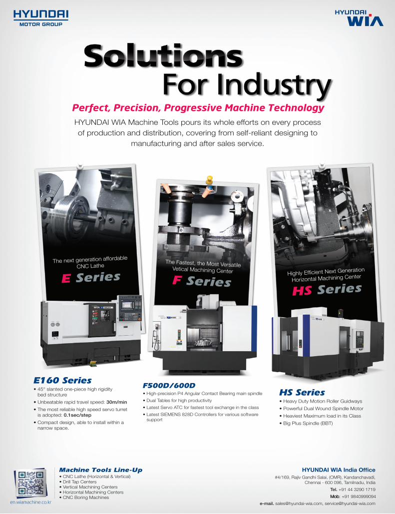
The next generation affordableCNC Lathe
E Series Highly Efficient Next Generation
Horizontal Machining Center
HS Series
The Fastest, the Most VersatileVetical Machining Center
F Series
HS Series• Heavy Duty Motion Roller Guidways• Powerful Dual Wound Spindle Motor• Heaviest Maximum load in its Class• Big Plus Spindle (BBT)
E160 Series• 45° slanted one-piece high rigidity
bed structure• Unbeatable rapid travel speed: 30m/min• The most reliable high speed servo turret
is adopted: 0.1sec/step• Compact design, able to install within a
narrow space.
F500D/600D• High-precision P4 Angular Contact Bearing main spindle• Dual Tables for high productivity• Latest Servo ATC for fastest tool exchange in the class• Latest SIEMENS 828D Controllers for various software
support
Perfect, Precision, Progressive Machine Technology
HYUNDAI WIA Machine Tools pours its whole efforts on every process of production and distribution, covering from self-reliant designing to
manufacturing and after sales service.
HYUNDAI WIA India Office#4/169, Rajiv Gandhi Salai, (OMR), Kandanchavadi,
Chennai - 600 096, Tamilnadu, India Tel. +91 44 3290 1719MMMooobbb: +91 9840999094
e-mail. [email protected], [email protected]
Machine Tools Line-Up• CNC Lathe (Horizontal & Vertical)• Drill Tap Centers• Vertical Machining Centers• Horizontal Machining Centers• CNC Boring Machines
en.wiamachine.co.kr