eddy current testing
TRANSCRIPT

Process and Equipment Design Projects
Salient Features
1. Eddy Current and Magnetic Testing on equipments.
2. Rolling, Forging and Extrusion of metal.

EDDY CURRENT TESTING(ECT)

Index
About ECT
Basic governing laws
Working principle
Components’ Description
Detection of cracks
Determination of thickness
Other applications
Advanced techniques in ECT
Advantages of ECT
Limitations of ECT
Summary
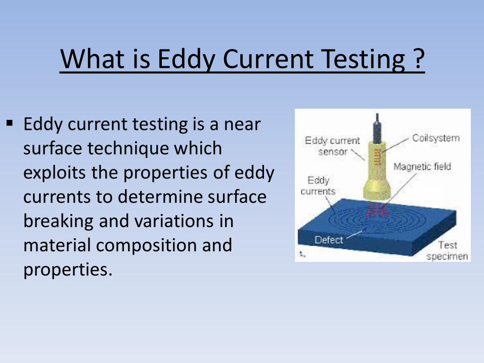
What is Eddy Current Testing ?
Eddy current testing is a near surface technique which exploits the properties of eddy currents to determine surface breaking and variations in material composition and properties.
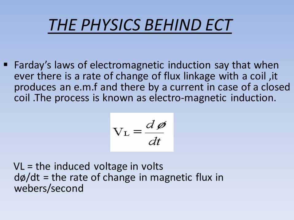
THE PHYSICS BEHIND ECT
Farday’s laws of electromagnetic induction say that when ever there is a rate of change of flux linkage with a coil ,it produces an e.m.f and there by a current in case of a closed coil .The process is known as electro-magnetic induction.
VL = the induced voltage in volts
dø/dt = the rate of change in magnetic flux in webers/second

WORKING PRINCIPLE • In standard eddy current a probe coil carrying ac current is
placed near the specimen which produces alternating magnetic flux around the coil.
• The alternating magnetic flux links with the testing material induces eddy currents.
• Then the variation of the magnitude and phase of these eddy current is monitored by using a search coil or by the same coil by measuring the change in current or impedance of primary search coil.

FORMATION OF EDDY CURRENT
• In ECT the eddy currents are generated in the testing material due to the phenomenon of mutual inductance
• The ac current in the probe coil produces alternating magnetic flux and these flux produce eddy current in the test material.

PROPERTIES OF EDDY CURRENTS
• Eddy currents are closed loops of induced currents circulating in planes perpendicular to magnetic flux
• They are confined to the area of inducing magnetic field
• Eddy currents concentrate near the surface adjacent to an excitation coil and strength decreases with distance from the coil

EFFECT OF EDDY CURRENT
• The eddy current produce a magnetic flux which links with the magnetic flux of the exciting coil.
• The amount of interaction between two fluxes determine the value of current or change in impedance of the primary coil and is a direct measurement of eddy current in the specimen.

MEASUREMENT OF EDDY CURRENT
• The change in impedance of the probe can be easily detected by a high sensitive maxwell’s induction bridge.
• It compares the inductance of the probe with some standard values and any change in this is reflected through a detecting coil or an oscilloscope

Penetration depth
• Due to skin effect the magnitude of eddy current decreases as depth of material increases
• The depth of penetration is given by the formula written on the right side.
BASIC COMPONENTS OF ECT
• PROBES
• DETECTING INSTRUMENTS
• DISPLAY UNITS
• FREQUENCY GENERATOR
• FILTERS
• AUXILLIARIES

PROBES
• It contains the coil to produce varying magnetic field
• It is designed in different manner as for the accessibility of the testing material
• It is designed so as to reduce the stray fields

1. Surface probes - Used for identifying flaws on and below metal surfaces, usually
large diameter to accommodate lower frequencies for deeper penetration, or for
scanning larger areas.
2. Pencil probes - Smaller diameter probes housing coils built for high frequencies for high resolution of near surface flaws.
3. Bolt hole probes - Designed to inspect the inside of a bolt hole. These probes can
be rotated by hand or automatically using a rotary scanner.
4. Donut probes - Designed to inspect aircraft fastener holes with fasteners in place.
5. Sliding probes - Also used in testing aircraft fastener holes, offering higher scan
rates than donut probes.
6. ID probes - Used for inspection of heat exchangers and similar metal tubing from the
inside, available in a variety of sizes.
7. OD probes - Used for inspection of metal tubing and bars from the outside, with the
test piece passing through the coil.

DETECTING INSTRUMENTS
• Display analog meter
• Oscilloscope
• Spectrum analyzer
• R-X plotter
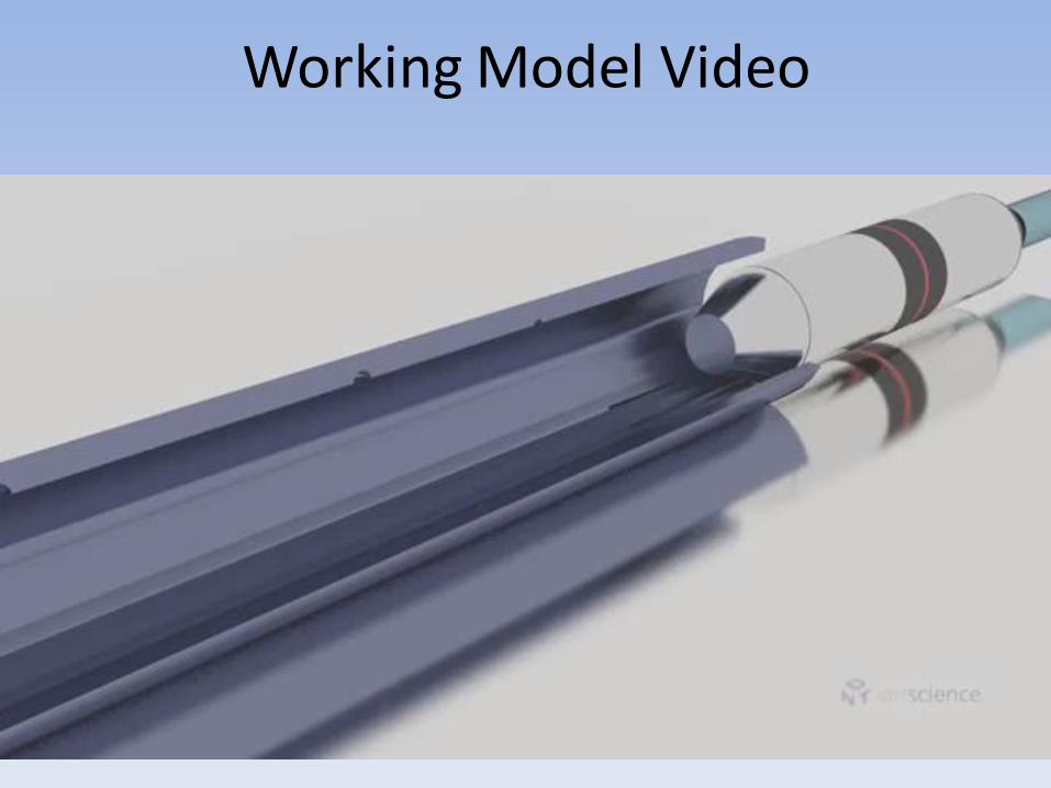
Working Model Video

APPLICATIONS OF ECT
• Surface crack detection
• Measurement of conductivity of materials
• Thickness measurement of non conductive coatings
• Tube inspection
• Heat damage inspection
• Material Identification

SURFACE BRAKING DETECTION
• The basic principle behind this that whenever there is a surface crack ,it disrupts the path of eddy currents.
• Due to this disruption the flux linkage in primary coil changes, which can be detected by the bridge circuit.

Thickness measurement of non conductive coating
• The thickness of non metallic coating on metal substance can be detected by simply the effect of lift off impedance.
• This is basically used for measuring thickness of paint and plastic coatings.

TUBE INSPECTION
In tube inspection the long tubes are inspeted through a long probe which is inserted into the tube and the condition of material inside the tube is determine from the impedance measurements.

ADVACED TECHNOLOGY IN ECT
• The advanced technology uses multiple frequency technique or swept frequency technique.
• This technique simple involve collecting data at several frequencies and then comparing the data or mixing the data in some particular manner.

APPLICATION OF SWEPT FREQUENCY TECHNIQUE
• To detect thickness of conductive coating over conductive material.
• Measurement of flaws in multi layer materials

ADVANTAGES OF ECT
• Sensitive to small cracks and other defects • Detects surface and near surface defects • Inspection gives immediate results • Equipment is very portable • Method can be used for much more than flaw
detection • Minimum part preparation is required • Test probe does not need to contact the part • Inspects complex shapes and sizes of conductive
materials
LIMITATIONS OF ECT
• Only conductive materials can be inspected • Surface must be accessible to the probe • Skill and training required is more extensive than other
techniques • Reference standards needed for setup • Surface finish and roughness may interfere • Depth of penetration is limited • Flaws such as delimitations that lie parallel to the probe
coil winding and probe scan direction are undetectable

SUMMARY
From the above discussion we can summaries that
eddy current testing (ECT) is one of the most important
testing technique which is now a days gaining popularity
due to its low cost equipment, immediate results oriented
testing ,accuracy of results and its wide range of application.

Magnetic Current Particle Testing

Introduction
• It is a non-destructive testing method used for defect detection.
• It uses magnetic fields and small magnetic particles (i.e. iron filings)
to detect flaws in components.
• The component being inspected must be made of a ferromagnetic material ( iron, nickel, cobalt, their alloys). Ferromagnetic materials can be magnetized to a level ,thus the inspection becomes effective.
• It is a combination of two non-destructive testing methods:
magnetic flux leakage testing and visual testing .

Industrial Applications
• Used to inspect a variety of product forms including castings, forgings, and weldments.
• The structural steel, automotive, petrochemical, power generation, and aerospace industries use MPI.
• Underwater inspection is another area where it is used to test items such as offshore structures and underwater pipelines .

Simple bar magnet
• It has a magnetic field in
and around the magnet. • Any place that a
magnetic line of force exits or enters the magnet is called a pole.
• A pole where a magnetic line of force exits the magnet is called a north pole and where a line of force enters the magnet is called a south pole.

Basic Principles
• If the magnet is just cracked but not broken
completely in two, a north and south pole will form at each edge of the crack.
• The magnetic field spreads out when it encounters the small air gap created by the crack
• This is because the air cannot support as much magnetic field per unit volume as the magnet can
• Magnetic field appears to leak out of the material and, thus is called a flux leakage field.


• If iron particles are sprinkled on a cracked magnet, the particles will be attracted to and cluster not only at the poles at the ends of the magnet, but also at the poles at the edges of the crack.
• This cluster of particles is much easier to see than the actual crack and this is the basis for magnetic particle inspection.

Basic overview of the process
• The first step in a magnetic particle inspection is to magnetize the component that is to be inspected.
• If any defects on or near the surface are present, the defects will create a leakage field.
• After the component has been magnetized, iron particles, either in a dry or wet suspended form, are applied to the surface of the magnetized part.
• The particles will be attracted and cluster at the flux leakage fields, thus forming a visible indication that the inspector can detect.
Portable Magnetizing Equipment for Magnetic Particle Inspection
• The requirement for detecting a defect in a ferromagnetic material is that the magnetic field induced in the part must intercept the defect at a 45 to 90 degree angle.
• Flaws that are normal (90 degrees) to the magnetic field will produce the strongest indications because they disrupt more of the magnet flux.
• Therefore, for proper inspection of a component, it is important to be able to establish a magnetic field in at least two directions.
• A variety of equipment exists to establish the magnetic field for MP.

Electromagnet
• most of the equipment used to create the magnetic field used in MPI is based on electromagnetism.
• It uses an electrical current to produce the magnetic field
• An electromagnetic yoke is a very common piece of equipment that is used to establish a magnetic field.
• Yoke is made by wrapping an electrical coil around a piece of soft ferromagnetic steel. A switch is included in the electrical circuit so that the current and, therefore, the magnetic field can be turned on and off.
• They can be powered with alternating current from a wall socket or by direct current from a battery pack.

Electromagnet

Magnetic Particles
• Particles start out as tiny milled (a machining process) pieces of iron or iron oxide. A pigment (somewhat like paint) is bonded to their surfaces to give the particles color.
• The metal used for the particles has high magnetic permeability and low retentivity.
• High magnetic permeability is important because it makes the particles attract easily to small magnetic leakage fields from discontinuities, such as flaws.
• Low retentivity is important because the particles themselves never become strongly magnetized so they do not stick to each other or the surface of the part. Particles are available in a dty mix or wet solution.

Suspension Liquids
• Suspension liquids used in the wet magnetic particle inspection method can be either a well refined light petroleum distillate or water containing additives.
• Petroleum-based liquids are the most desirable carriers because they provided good wetting of the surface of metallic parts. However, water-based carriers are used more because of low cost, low fire hazard, and the ability to form indications quicker than solvent-based carriers.
• Water-based carriers must contain wetting agents to disrupt surface films of oil that may exist on the part and to aid in the dispersion of magnetic particles in the carrier.

• The wetting agents create foaming as the solution is moved about, so anti-foaming agents must be added. Also, since water promotes corrosion in ferrous materials, corrosion inhibitors are usually added as well.
• Petroleum based carriers are primarily used in systems where maintaining the proper particle concentration is a concern. The petroleum based carriers require less maintenance because they evaporate at a slower rate than the water-based carriers.
• Therefore, petroleum based carriers might be a better choice for a system that gets only occasional use or when regularly adjusting the carrier volume is undesirable.
• Modern solvent carriers are specifically designed with properties that have flash points above 200oF and keep nocuous vapours low.

Stationary Equipment • Stationary magnetic particle inspection
equipment is designed for use in laboratory or production environment.
• The most common stationary system is the wet horizontal (bench) unit. Wet horizontal units are designed to allow for batch inspections of a variety of components. The units have head and tail stocks (similar to a lathe) with electrical contact that the part can be clamped between. A circular magnetic field is produced with direct magnetization.

• It does not need very powerful pre-cleaning operation.
• Best method for the detection of fine,
shallow surface cracks in ferromagnetic material.
• Relatively simple NDT method.
•Generally inexpensive.
• Will work through thin coating.
•Only few limitations regarding the size/shape of test
specimens.
• Highly portable NDT method.
•It is quicker.
ADVANTAGES
LIMITATIONS:
•Material must be ferromagnetic.
• Orientation and strength of magnetic field is
critical.
• Detects surface and near-to-surface
discontinuities
only.
• Large currents sometimes required.
• “Burning” of test parts a possibility.
• Parts must often be demagnetized, which may
be
difficult.