elevator systems inc. · elevator systems inc. hydrualic elevator controller model 2kx ... cpu,...
TRANSCRIPT
D21.3001.A01 Page
1
Elevator Systems Inc.
HYDRUALIC ELEVATOR CONTROLLER
MODEL 2KX
OPERATION MANUAL
© Elevator Systems Inc. MANUAL #D21.2001.D01 10/1/14
465 ENDO BLVD., GARDEN CITY, NEW YORK 11530 · TEL: (516) 239-4044 · FAX: (516) 239 5793

D21.2001.D01 PAGE 1/32
Table of Contents
HYDRUALIC ELEVATOR CONTROLLER ......................................................................................................... 1 OPERATION MANUAL............................................................................................................................................ 1 Table of Contents ........................................................................................................................................................ 1 CONVENTIONS ......................................................................................................................................................... 3 LEGEND...................................................................................................................................................................... 4 CONTROLLER COMPONENT OVERVIEW........................................................................................................ 8 SYSTEM INPUTS....................................................................................................................................................... 9 SYSTEM OUTPUTS................................................................................................................................................. 11 LCD Keypad Description: ........................................................................................................................................ 13
MODE : Used to change LCD Display Mode. ............................................................................. 13 MAIN CPU MONITOR LCD SCREEN................................................................................................................. 14 EVENT LOG ............................................................................................................................................................. 17 View and Edit Parameters........................................................................................................................................ 18 PRE POWER CHECK OUT ................................................................................................................................... 18 INITIAL POWER TURN ON.................................................................................................................................. 19 SEQUENCE OF OPERATION ............................................................................................................................... 20
TOP OF CAR INSPECTION............................................................................................................................... 21 IN CAR INSPECTION......................................................................................................................................... 22 HOISTWAY ACCESS.......................................................................................................................................... 22 CONTROLLER INSPECTION........................................................................................................................... 23 AUTOMATIC OPERATION .............................................................................................................................. 23 DETAILED RUNNING RELAY SEQUENCE .................................................................................................. 24 CYCLE TEST........................................................................................................................................................ 24 CT TROUBLE SHOOTING ................................................................................................................................ 25 CYCLE TEST........................................................................................................................................................ 25 CT TROUBLE SHOOTING ................................................................................................................................ 26 Ups Lowering Mode.............................................................................................................................................. 28 Thermal Overload Mode ...................................................................................................................................... 28
NTS TEST.................................................................................................................................................................. 28 PARAMETER LIST................................................................................................................................................. 29

D21.2001.D01 PAGE 2/32
H-DRVBOARD
DOORBOARD
RBBOARD
208/120250 VA
RPR
SOFT START
24VDC
S1
ACCESSBOARD
PF
-5K
VERT TERM
ESI CPU BOARD
I/O BOARD
I/O BOARD
FUSES
STANDARD HPC2K CONTROLLER LAYOUT

D21.2001.D01 PAGE 3/32
CONVENTIONS This manual uses the following terms and conventions to indicate parts of the controller and operation: CPU – The electronic controller board and all of it’s associated expansion boards. Energized – Power is applied to the relay coil, and the relay has operated. De-energized – Power is not applied to the relay coil, and the relay is at rest. Activated – A signal is applied to the input terminal on the CPU or CPU expansion board. De-activated – A signal is not applied to the input terminal on the CPU or CPU expansion
board. Symbol – a letter or letter number code referring to a relay or terminal.
Example: PX
Symbol number/number – A contact pair on a relay Example: PX 1/7
Symbol{number} – An input / output on the CPU board.
Example: A{1}
Symbol{number-number} – An input / output on an expansion board. The first number indicates which I/O board, the second indicates the terminal. Example: 1C{1-13}
#symbol - A terminal on the connection terminal strip.
Example: #OF1
#symbol to #symbol – Indicates an external electrical connection between two terminals. Example: #27 to #28

D21.2001.D01 PAGE 4/32
LEGEND Table 1 outlines the symbols used in the ESI Drawings. Please refer to this table whenever you have any questions regarding symbols on the ESI Drawings.
Symbol Symbol Name Notes
Fuse
Top Number represents the fuse number. Bottom Number represents the Amperage.
Terminal
The Lettering (beginning with#) represents the terminal name.
Normally Open Contact
(Contactor)
The Lettering represents the Contactor Name (i.e. P) and the Number represents the Contact Number (i.e. 1)
Normally Closed
Contact (Contactor)
The Lettering represents the Contactor Name (i.e. P) and the Number represents the Contact Number (i.e. 6)
Normally Open Contact
(Relay)
The Lettering represents the Relay Name (i.e. Z) and the Numbers represents the Relay Terminals (i.e. 1 and 7)
Normally Closed Contact (Relay)
The Lettering represents the Relay Name (i.e. I) and the Numbers represents the Relay Terminals (i.e. 5 and 8)
Relay Coil
The Lettering represents the Relay Name (i.e. TC). The small circle to the right of the Relay represents the Right Terminal of the Coil.
Resistor
The Lettering represents the resistor value (i.e. 15kΏ)
Capacitor
The Lettering represents the capacitance value (i.e. 40µF)
Diode

D21.2001.D01 PAGE 5/32
Switch
The Lettering represents the name of the switch (i.e. BOT FINAL). NOTE: Switch shown in Closed Position.
Region
This symbol is used to refer to a different area on the drawing (i.e. Area Labeled H)
Resistor
The Lettering represents the resistor value (i.e. 150Ώ)
Resistor (Tapped) The Lettering represents the resistor value (i.e. 250Ώ)
Switch
The Lettering represents the name of the switch (i.e. PIT SWITCH). NOTE: Switch shown in Closed Position.
GOV. SW
Switch
The Lettering represents the name of the switch (i.e. GOVERNOR SWITCH). NOTE: Switch shown in Closed Position.
Transformer
The Lettering on the Left Side represents the Primary Voltage (i.e. 208VAC) and the Lettering on the Right Side represents the Secondary Voltage (i.e. 120VAC).
Switch
The Lettering represents the name of the switch (i.e. FX). NOTE: Switch shown in Open Position.
CPU Inputs
The Lettering represents the Input name (i.e. SW, GS, and DLK). The Numbers represent the Input location. (i.e. SW = IN 5, GS = IN 6, DLK = IN 7).
CPU Inputs
The Lettering represents the Input name (i.e. 38 38

D21.2001.D01 PAGE 6/32
CPU Outputs
The Numbers represent the Output Number on the CPU (i.e. Drawing is showing Outputs 18 and 19).
Dry Contact Outputs
The Lettering represents the Dry Contact Output name. The Number represents the Output Number (i.e. Dry Contact Output URP, Output number 2).
Key Switch
The Lettering represent the Switch Name (i.e. IN CAR FIREMAN KEY SW) and the Pole Names (i.e. OFF, ON and HOLD). Three position key switch pictured.
Push Button
The Lettering represents the Button Name (i.e. IN CAR FIREMAN RESET BUTTON).
Overload
Current Sensing Portion of the Overload Protection.
Light
The Lettering represents the name of the Light (i.e. UP).
Buzzer
The Lettering represents the name of the Buzzer (i.e. Door Delay Buzzer).
Hall Lantern
Board Connector
The Lettering represents the connector name (i.e. J1). The number represents the Pin (i.e. 5).
5 J1

D21.2001.D01 PAGE 7/32
Variable Timer Delay
Switch
The Lettering represents the name of the switch (i.e. IN CAR STOP SWITCH). NOTE: Switch shown in Closed Position.

D21.2001.D01 PAGE 8/32
CONTROLLER COMPONENT OVERVIEW
The controller is designed for maximum reliability with minimum maintenance. A unique and robust CPU, coupled with a series of forced guided relays, provide all the functionality necessary to run the elevator. The CPU unit provides the control logic. The safety circuits are controlled by both the CPU and relay structure for maximum reliability and redundancy in all modes of operation . A board mounted Siemens soft start controls the pump motor and provides motor overload and fault protection. All relays have an internal indicator light (a board mounted LED for board mounted relays) that illuminates when power is provided to the relay coil. This allows the status of all relays to be verified quickly. In addition, the CPU module has red indicator lights for each input, green indicator lights for each output, and a 4 line display to indicate system status. A reverse phase relay on the board provides reverse phase protection to the controller. An optional Uninterruptible Power Supply (UPS) can provide ‘backup’ power to lower the elevator in case of a power or phase failure.
Every controller has three toggle switches. These are: test mode, hall button disconnect and automatic/inspection. There are also three push button inputs on every controller: controller inspection down, enable and up. There are also two slide switches: Car Door Bypass and Hatch Door Bypass. A vertical terminal strip provides all interconnecting to the elevator’s equipment. The relays, Inputs and Outputs names and functions are described in the following tables:
Relay Names: RELAY NAME
FUNCTION TYPE LOCATION
D/DX Run Down 2 Pole Safety BRD_DRV_HHS High speed 2 Pole Safety BRD_DRV_HHSP High speed Aux 2 Pole Safety BRD_DRV_HHSX High speed Aux 2 Pole Safety BRD_DRV_HHSY High speed Aux 2 Pole Safety BRD_DRV_HHSZ High speed Aux 2 Pole Safety BRD_DRV_HJS Jack Synchronization 2 Pole Safety BRD_DRV_HPF Phase protection KUP BRD_DRV_HPX Running Aux 2 Pole Safety BRD_DRV_HR Run Pump 2 Pole Safety BRD_DRV_HU/UX Run Up 2 Pole Safety BRD_DRV_HUT Up Delay Out 2 Pole Safety BRD_DRV_H I / IX Inspection – Energized on Automatic/ in car 2 Pole Safety RB Board IC1 / IC2 In car inspection – Energized on InCar Insp. 2 Pole Safety RB Board ID Inspection Down 2 Pole Safety RB Board IU Inspection Up 2 Pole Safety RB Board LFI Lobby Fire Light 2 Pole Safety RB Board CT Cycle Test 2 Pole Safety RB Board SWB Stop switch bypass 2 Pole Safety RB Board

D21.2001.D01 PAGE 9/32
SWB2 Stop switch bypass Redundant 2 Pole Safety RB Board DL Door Locks 2 Pole Safety Door Board GS Gate Switch 2 Pole Safety Door Board VC Leveling 2 Pole Safety Door Board Z Door Zone 2 Pole Safety Door Board ACC Access 6 Pole Safety Access Board ACX Access Aux. Relay 6 Pole Safety Access Board BAC Access Bottom Control 6 Pole Safety Access BoardTAC Access Top Control 6 Pole Safety Access Board
SYSTEM INPUTS Main CPU Board Inputs: Bottom Row: INPUT Symbol FUNCTION 1 ON 120 VAC power on 2 TC Top Car Inspection (when de-activated) 3 IC In Car Inspection (when de-activated) 4 ACC Access 5 I Controller Inspection (when de-activated) 6 ID Inspection Down 7 IU Inspection Up 8 SAF All Safeties Closed 9 SW Stop Switch Closed 10 SPARE 11 GS Gate Switch 12 DL Hatch Door Lock 13 84 Door Zone 14 DRV Doors/Gate/Inspection 15 OV Top Normal 16 !PF Power Failure (when activated) 17 52 Bottom Slowdown Limit 18 53 Top Slowdown Limit 19 TOL Thermal Overload 20 FLT Soft Start Fault 21 SPARE
Top Row

D21.2001.D01 PAGE 10/32
INPUT Symbol FUNCTION 22 24 Door Close Button 23 28 Door Open Button 24 28E Door Electric Eye 25 28S Door Safety Edge 26 29 Door Quick Close Input, car button 2nd poles wired in parallel 27 47 Door Close Limit 28 48 Door Open Limit 29 50 Independent Service Key Switch 30 81 Down Level Unit 31 82 Up Level Unit 32 85 Down Stepping signal 33 86 Up Stepping signal 34 86 At FCF Floor signal 35 SPARE 36 90 Smoke / Heat Detectors (Alternate Return) 37 92 Smoke / Heat Detectors (Prime Return) 38 92B Machine Room Sensors / Heat Detectors (Prime Return) 39 93 Fire Control Lobby Switch (BYPASS) 40 94 Fire Control Lobby Switch (ON) 41 95 Fire Control Car Switch (ON) 42 96 Fire Control Car Switch (RESET) 43 99 Fire Control Car Switch (HOLD) 44 100 Fire Control Car Switch (OFF) 45 90B Machine Room Smoke / Heat Detectors (Alternate Return)
Aux Input Board : To the right of LCD display INPUT Symbol FUNCTION AUX Board P1 Proving Input 1 AUX Board P2 Proving Input 2 AUX Board P3 Proving Input 3 AUX Board TST Test Switch Input AUX Board GB Car Door Bypass AUX Board DBY Hoistway Door Bypass

D21.2001.D01 PAGE 11/32
I/O #1 Expansion Board Inputs: 1 1H First Floor Hall Call 2 2D Second Floor Down Hall Call 3 2U Second Floor Up Hall Call 4 3D Third Floor Down Hall Call 5 3U Third Floor Up Hall Call 6 4D Fourth Floor Down Hall Call
7 4U Fourth Floor Up Hall Call
8 SPARE 9 1K First Floor Key Switch 10 2K Second Floor Key Switch 11 3K Third Floor Key Switch 12 4K Fourth Floor Key Switch 13 1C First Floor Car Call 14 2C Second Floor Car Call 15 3C Third Floor Car Call 16 4C Fourth Floor Car Call
SYSTEM OUTPUTS Main CPU Board Outputs: Bottom Row: OUTPUT Symbol FUNCTION 1 CT Cycle Test 2 JS Jack Synchronization 3 SWB Stop Switch Bypass Pilot 4 VC Leveling Pilot 5 SPARE 6 HSP High Speed Pilot 7 OX Door Open Pilot 8 CX Door Close Pilot 9 NR Nudging Pilot 10 PP Run Pilot 11 DRP Down Run Pilot

D21.2001.D01 PAGE 12/32
Top Row: OUTPUT Symbol FUNCTION 12 21 Down Directional Light 13 23 Up Directional Light 14 61 Stop / Pass Gong 15 97 Fire Control Light 16 97B Fire Buzzer 17 LFI LFI Pilot 18 DG Down Car Travel Lantern 19 UG Up Car Travel Lantern 20 URP Up Run Pilot 21 RP Up Pump Pilot
I/O #1 Expansion Board Outputs: 1 1HA First Floor Hall Call Acknowledge 2 2DA Second Floor Down Hall Call Acknowledge 3 2UA Second Floor Up Hall Call Acknowledge 4 3DA Third Floor Down Hall Call Acknowledge 5 3UA Third Floor Up Hall Call Acknowledge 6 4DA Fourth Floor Down Hall Call Acknowledge 7 4UA Fourth Floor Up Hall Call Acknowledge 8 SPARE 9 1I First Floor Indicator 10 2I Second Floor Indicator 11 3I Third Floor Indicator 12 4I Fourth Floor Indicator 13 1A First Floor Car Call Acknowledge 14 2A Second Floor Car Call Acknowledge 15 3A Third Floor Car Call Acknowledge 16 4A Fourth Floor Car Call Acknowledge

D21.2001.D01 PAGE 13/32
LCD Keypad Description: A 20 * 4 character backlit LCD with a 5 position keypad makes up the integrated user interface On all of Elevator Systems ESI-C Elevator control systems. MODE : Used to change LCD Display Mode.
: To Scroll Down through various display screens and to adjust parameter settings.
: To Scroll Up through various display screens and to adjust parameter settings. CLR : To Clear current parameter editing and to force a drive reset without time delay SET : Used to enter parameter settings and adjust operational information. Display Modes: 1. ESI Mon : Main Screen for monitoring current status of elevator 2. Job Info : Contains Controller Serial Number and Job address 3. View I/O : Use arrow to scroll through all system inputs and outputs 4. Internal Flags : View Internal flags status 5. Event Log : Scroll through events with time/date stamp 6. Place Car Call : To place car calls into system 7. Place Hall Call : To place hall calls into system 8. Parameters : Scroll through to edit desired parameter 9. Setup : Scroll through various setup options 10. Mem View : View ROM,RAM & EE2 memory 11. System Info : Software version information 12. Future1 : 13. Future2 :

D21.2001.D01 PAGE 14/32
MAIN CPU MONITOR LCD SCREEN Inspection Status Operation Status Car Action/Fault Status: Direction Preference and Bypass Status:
ESI Mon 8:10:01 AM Automatic : Normal Up High Speed Car at :1 US
1) Access 2) Automatic 3) ByPass 4) Cont. Insp. 5) InCar Insp 6) TOC Insp
1) Attn Serv 2) BackUpPWR 3) EMT Serv 4) EMT InCar 5) EQ-Sem 6) EQ-Sem& CW 7) EQ-Cwt 8) Emg Power 9) Emg PR PK 10) FCF Prime 11) FCF PII 12) FCF Alt 13) FCF AII 14) Ind Serv 15) Low Oil 16) Normal 17) OutOfServ 18) TEST Mode
1) ACC DnDirLIMIT OPEN 2) ACC UpDirLIMIT OPEN 3) BackUpPWR DelayCHK 4) BrakeSW Err on Run 5) BrakeSW Err on STOP 6) CarHeld TOS 7) CAR DOOR OPEN 8) Cpu Powered by Bcar 9) CX/DLK/NotRun TOS 10) CYCLE Test Failure 11) DOOR CLOSED 12) DOOR CLOSING 13) DOOR FULL OPEN 14) DOOR OPENING 15) DOOR/GATE CLOSED 16) DN HIGH SPEED 17) DN FLOOR SEEK 18) DN SLOW SPEED 19) DN LEVELING 20) DRIVE ERROR 21) ESL Trip 22) GovOverSpdSW OPEN 23) HATCH DOOR OPEN 24) HATCH DR/GATE OPEN 25) No Control 120VAC 26) OLR/RPR/DC Open 27) Thermal OVLD Trip 28) RC Locking Doors 29) GRP1/2 Cyc TEST Fail 30) ROPEGrp TRIPPED OVS 31) ROPEGrp TRIPPED UAM 32) ROPEGrp TRIPPED BKW 33) ROPEGrp TRIPPED 34) Safeties OPEN 35) STOP SW OPEN 36) UP HIGH SPEED 37) UP FLOOR SEEK 38) UP SLOW SPEED 39) UP LEVELING
1) US : Up Direction 2) UG : Up Preference 3) DS : Down Direction 4) DG : Down Preference 5) DBy: Door Bypass 6) GBy: Gate Bypass 7) DGB: Door and Gate Bypass

D21.2001.D01 PAGE 15/32
Inspection Status: Operation Status: Direction Preference and Bypass Status:
1) Access : On TOP or BOTTOM ACCESS 2) Automatic : On Automatic Operation 3) ByPass : Illegal Condition Car Door and/or Hoistway Door Bypass switch is up when not on TOC/InCar Isnp 4) Cont Insp : On controller inspection 5) InCar Insp : On InCar Inspection 6) TOC Insp : On Top of Car Inspection
1) Attn Serv : On attendant Service, CPU input “#70” high 2) BackUpPWR : On UPS Backup Power, relay PF de-energized, CPU input 16 high 3) EMT Serv : On Emergency Medical Team Service 4) EMT InCar : On Emergency Medical Team Service in Car 5) EQ-Sem : Earth Quake-Seismic Trip only 6) EQ-Sem&CW : Earth Quake-Seismic & Counter Weight Trip 7) EQ-Cwt : Earth Quake Counter Weight Trip only 8) Emg Power : On Back-up Power 9) Emg PR PK : On Back-up Power and Auto returning 10) FCF Prime : Fire Control Phase I Prime Return 11) FCF PII : Fire Control Phase II Prime Return 12) FCF Alt : Fire Control Phase I Alt Return 13) FCF AII : Fire Control Phase II Alt Return 14) Ind Serv : On Independent Service, Input “#50” is high 15) Low Oil : Low Oil Trip due to the car traveling UP for more than (Para 48) secs, default 45 sec. Toggle to Inspection to clear 16) Normal : Controller is operating Normally 17) OutOfServ : Car is Out Of Service 18) TEST M d C ill h ll ll d h d h P i DOB(#28) ill h d
1) US : Up Direction 2) UG : Up Preference 3) DS : Down Direction 4) DG : Down Preference 5) Dby : Hatch Door Bypassed via slide switch on RB board 6) Gby : Gate Switch Bypassed via slide switch on RB board 7) DGB : Both the Hatch Door and Gate Switch are Bypassed by slide switches on the RB board

D21.2001.D01 PAGE 16/32
Car Action/Fault Status:
1) ACC DnDirLIMIT OPEN : Top Access down travel has been limited by the encoder count, only up travel possible 2) ACC UpDirLIMIT OPEN : Bot Access up travel has been limited by the encoder count, only down travel possible 3) BackUpPWR DelayCHK : Delay before going on Back Up Power 4) BrakeSW Err on Run : Brake Switch did no open on run . Toggle to Inspection to clear 5) BrakeSW Err on STOP : Brake Switch did not close on stop . Toggle to Inspection to clear 6) CarHeld TOS : Car held, Timed Out of Service 7) CAR DOOR OPEN : Doors are open 8) Cpu Powered by Bcar : Acar lost power, Bcar is providing power to the A CPU and hall call/FCF feeds 9) CX/DLK/NotRun TOS : Car timed out of service Door contacts did not make up on close or the Door Close Limt did not open 10) CYCLE Test Failure : The P1, P2 and P3 inputs failed to turn on in the proper sequence 11) DOOR CLOSED : The Door Close Limt is low, and the Open Limit is high. 12) DOOR CLOSING : Door close output signal (CX) is high 13) DOOR FULL OPEN : The Door Close Limt is high, and the Open Limit is low 14) DOOR OPENING : Door open output signal (OX) is high 15) DOOR/GATE CLOSED : Input DO is High on jobs with manual or power freight doors & gates 16) DN HIGH SPEED : Car is running in the Down direction and relay HSP is energized 17) DN FLOOR SEEK : Running in the Down direction, seeking the next door zone 18) DN SLOW SPEED : Car is running in the Down direction. HSP is out. Looking for the next leveling magnet 19) DN LEVELING : Car is running Down with #81 & #84 ON, when #81 goes low the car will stop 20) DRIVE ERROR : Error signal from drive. Check drive fault history for error codes 21) ESL Trip : Car did not slow down sufficiently before breaking the inner slow down limit. Toggle inspection to reset this fault 22) GovOverSpdSW OPEN : Governor over speed switch is open. Input “OVS” is low 23) HATCH DOOR OPEN : Input “DO” is low on jobs with swing hatch doors 24) HATCH DR/GATE OPEN : Input “DO” is low on jobs with manual or power freight doors 25) No Control 120VAC : CPU input 1 is low 26) OLR/RPR/DC Open : Input “OV” cpu input 15 is not on when car is trying to run. DC relay must be energized. Check Overload is not tripped and the Reverse Phase Relay is on 27) Thermal OVLD Trip : The motor heat sensor , input “TOL” , is open 28) RC Locking Doors : “RC” output is on. 29) GRP1/2 Cyc TEST Fail : Rope Gripper control relays did not complete their cycle test, (200 fpm or less) input “!RG” did not cycle properly (more than 200 fpm) input “!RG1” or “!RG2” did not cycle properly 30) ROPEGrp TRIPPED OVS : Rope Gripper Tripped, governor tripped 31) ROPEGrp TRIPPED UAM : Rope Gripper Tripped, moved out of door zone with both the gate and the hatch doors open 32) ROPEGrp TRIPPED BKW : Rope Gripper Tripped, brake switch still open on stop 33) ROPEGrp TRIPPED : Rope Gripper Tripped, on power up 34) Safeties OPEN : “GOV input high”, but the “SAF” input low 35) STOP SW OPEN : “SAF input high”, but the “SW” input low 36) UP HIGH SPEED : Car is running in the Up direction and relay HSP is energized 37) UP FLOOR SEEK : Running in the Up direction, seeking the next door zone 38) UP SLOW SPEED : Car is running in the UP direction. HSP is out. Looking for the next leveling magnet 39) UP LEVELING : Car is running in UP with #82 & #84 ON, when #82 goes low the car will stop

D21.2001.D01 PAGE 17/32
EVENT LOG To view Event Log, press MODE until EVENT LOG screen comes up. Use up and down arrows to scroll through the events. To reset the event log, set PARAMETER 20=3,then press mode until the SETUP/UTILITIES screen comes up. Press up and down arrows to scroll to the CLEAR EVENT LOG screen. Press SET. Press SET again to reset EVENT LOG. Set PARAMETER 20 =0.
Event Log ### Code:### Atflr: ## Power On 1/10/01 12:10:00 AM
Floor car was at when Event was logged
Event Description: 1. Power On : Power was turned on 2. Event Log Cleared : Date and time when the event log was last cleared 3. On to Inspection : The Elevator was put onto inspection service 4. Normal Automatic : The Elevator went back to normal automatic service 5. InCar SW Opened : The in car stop sw was opened 6. reserved : 7. VF Drive Error : The VVVF drive tripped. Look at drive fault history for error codes 8. Independent Service : The car was placed onto independent service 9. FCF Phase One : The elevator responded to fire control 10. FCF Phase Two : The elevator was placed onto phase II fire service 11. reserved : 12. reserved : 13. Low Oil Time Out : Low Oil Trip due to the car traveling UP for more than (Para 48) secs, default 45 sec. 14. Emerg Power : The elevator was placed onto emergency power operation 15. BackUp Power : The elevator switched over to UPS/BackUp power 16. Attendant Service : The car was placed onto attendant service 17. Thermal OVLD Trip : The motor Thermal OVLD Trip “TOL” opened. 18. SAF opened : The safeties, input “SAF” opened 19. Gov OVS opened : The governor sw, input “OVS” opened 20. OVERspeed Trip : The Car exceeded the OVERspeed Trip Speed, set in parameter 185 27. RopeGrp/EmBrkTrp_OVS : Rope Gripper/ Emergency Brake Trip due to the governor switch opening 28. RopeGrp/EmBrkTrp_UAM : Rope Gripper/ Emergency Brake Trip due to unattended motion 29. RopeGrp/EmBrkTrp_BKSW : Rope Gripper/ Emergency Brake Trip due to the brake switch not closing on a stop 31. HSstopDL : A high speed stop occurred due to the hatch door contacts opening in flight 32. HSstopGS : A high speed stop occurred due to the car door contact opening in flight
Date / Time Stamp
Event Number 1 = the most recent
Event Code Number

D21.2001.D01 PAGE 18/32
View and Edit Parameters
PRE POWER CHECK OUT Prior to shipment, the controller is given a series of thorough tests to ensure proper operation. However, it is possible that components could have loosened or been damaged during shipment. Therefore, before applying power, it is a good idea to check the following: Check for loose components. Check that no components were bent in shipping
Check all rectifier connections are tight and not shorted
Make sure all plug in relays are fully inserted and seated. Check that all CPU terminal strips fully inserted
Make sure all toggle switches are in the down position. CONFIRM input power supply. The input power supply specifications are printed near the
terminals.
To View and edit parameters: 1. Use / keys to scroll to desired parameter. 2. Press SET to place into edit mode. The equal sign “=” will blink.
3. Use / keys to change parameter setting. 2. Press SET to save changes. The equal sign “=” will stop blinking. 3. If CLR is pressed prior to saving changes the previous value will be restored. 5. NOTE: Parameter #20 must be set to 3 to enable edit mode.

D21.2001.D01 PAGE 19/32
INITIAL POWER TURN ON
Check the voltage across terminals #L1, #L2 and #L3. Verify that the voltage reading is what the controller is built for. The RPR should be lit. If the RPR is not lit then reverse the #L1 and #L2 wires. Typically, voltage across the Primary side of the control transformer should be 208VAC and the voltage across the Secondary side of the transformer should be 120VAC. The Secondary side of the transformer ties into the RB board where power is routed to different parts of the controller. Verify the following terminal pairs should have 120VAC present: #27 - #60 #32 - #60 (with CT Relay energized) #91 - #60 With 120vac or 24vac signals verify the following terminal pairs have the proper voltage present: #31 - #60 (note this maybe 24vac if ack lts are setup for 24vac ) #30 - #60 (with Hall Button Switch ON, note this maybe 24vac if ack lts are setup for 24vac ) With 24 VDC signals verify the following terminal pairs have 24vdc which is feed from PS #2: #31 - #22 #30 - #22 (with Hall Button Switch ON) With ESI DPI’s only verify the following terminal pairs have 24vdc which is feed from PS #2: #1L - #2L If all voltages are within range and all safety circuits are properly wired, running the car on Top of Car Inspection should be done first. See the sequence of operation for a full description of this procedure.
CAUTION: High Voltage can cause serious and fatal injury. Extreme caution should be exercised when working on or near this controller. Only qualified personnel should attempt to start-up or troubleshoot this controller.

D21.2001.D01 PAGE 20/32
SEQUENCE OF OPERATION Before we can run the controller the safety mechanisms must all be in place. Verify that the following safety circuits are closed.
#32 - #32A : (if applicable) #32A - #33 : Final Limits #40 - #41 : Escape Hatch, Safety Sw, TOC Stop Sw (input “SAF” ON) #41 - #42 : InCar Stop Switch (input “SW” ON) #42 - #45 : Car Door Contact (input “GS” ON and relay “GS” ON)
Note: with Single Circuit Interlocks :
#34 - #34A : Bottom Hatch Door Interlock #34A - #34D : Inter Floor Hatch Door Interlock #34D - #35 : Top Hatch Door Interlock (input “DL” ON and relay “DL” ON)
Note: with Double Circuit Locks :
#34 - #34A : Bottom Hatch Door Contact #34A - #34D : Inter Floor Hatch Door Contacts #34D - #35 : Top Hatch Door Contact (input “DO” ON) #43 - #43A : Bottom Hatch Door Lock #43A - #43D : Inter Floor Hatch Door Locks #43D - #44 : Top Hatch Door Lock (input “DL” ON and relay “DL” ON)
#37 to #39 : Bottom Normal Limit #38 to #39 : Top Normal Limit

D21.2001.D01 PAGE 21/32
TOP OF CAR INSPECTION Relay that must be energized: RPR, DC and CT Relays that must be de-energized: ACC, ACX, I, IX, IC1, and IC2. Input “TC” should be off. Inputs that must be activated: ON, GOV, SAF, and SW. In order to move the car on Top of Car Inspection, constant pressure must be applied to the buttons. The buttons will allow voltage to flow from terminals #TI to #IU or #TI to #ID. The car will move up and down by energizing the IU or ID relay and it’s corresponding input.
CAUTION: Ensure that all personnel working on the elevator understand that the car will be moving during this procedure in both Up run and the Down run modes.
Top of Car Inspection UP RUN Pressing the Top of Car UP RUN and Safety button (#TI to #IU) will send a signal to the controller (via input 7-IU) that up motion is requested. Relay IU will pick, feed voltage to input “DRV” via a N/Open contact and thru N/Open “DC” contacts to input “OV”. The CPU will turn ON four outputs. Output 10 “URP” energizing relay U. Output 20 “BP” energizing relay B. Output 21 “DEN” energizing relay DEN. Output 8 “CX” energizing relay C which will force the doors closed (“if applicable”). The motor and brake will engage and the car will run up at inspection speed. The CPU display will read ‘Up Slow Speed’. Releasing the switch will stop the car immediately. Top of Car Inspection DOWN RUN Pressing the Top of Car DOWN RUN and Safety button (#TI to #ID) will send a signal to the controller (via input 6-ID) that down motion is requested. Relay ID will pick, feed voltage to input “DRV” via a N/Open contact and thru N/Open “DC” contacts to input “OV”. The CPU will turn ON four outputs. Output 11 “DRP” energizing relay U. Output 20 “BP” energizing relay B. Output 21 “DEN” energizing relay DEN. Output 8 “CX” energizing relay C which will force the doors closed (“if applicable”). The motor and brake will engage and the car will run down at inspection speed. The CPU display will read ‘Down Slow Speed’. Releasing the switch will stop the car immediately.

D21.2001.D01 PAGE 22/32
IN CAR INSPECTION Relays that must be energized: RPR, DC, CT, IC1 and IC2. Relays that must be de-energized: ACC, ACX, I, and IX. Inputs “IC” AND “ACC” should be OFF. Inputs that must be activated: ON, GOV, SAF, Swan TC. In order to move the car on In Car Inspection, constant pressure must be applied to the buttons. The buttons in the car station are used to control the car while on In Car Inspection. Voltage flow is controlled from #TI to #TC , and then to either #IC1 to #ICU (in order to run up) or #IC1 to #ICD (in order to run down). The car will move up or down by energizing the IU or ID relay and it’s corresponding input. The feed to relays IU and ID are also interrupted by NO contacts from IC1 and IC2 so these relays must be on to move while on In Car Inspection.
CAUTION: Ensure that all personnel working on the elevator understand that the car will be moving during this procedure in both Up run and the Down run modes.
HOISTWAY ACCESS Relays that must be energized: RPR, DC, CT, ACC and ACX. Relays that must be de-energized: I, IX, IC1, and IC2. Input “IC” should be OFF. Inputs that must be activated: ON, GOV, SAF, SW, TC, and ACC. In order to move the car on Access, constant pressure must be applied to the key switches. The key switches will allow voltage to flow from terminals #AC to either the ID relay or the IU relay via an ACC N/Open contact. Two other relays associated with Access are TAC and BAC. The TAC is energized by the Top Floor Access Key Switch, and the BAC is energized by the Bottom Floor Access Key Switch. The car will move up or down by energizing the IU or ID relay and it’s corresponding input. The GS N/Open contact is bypassed via “ACC” and either “BAC” or “TAC” N/Open contacts. The Bottom Hatch Door is bypassed via “ACX” and “BAC” N/Open contacts. The Top Hatch Door is bypassed via “ACX” and “TAC” N/Open contacts.

D21.2001.D01 PAGE 23/32
CAUTION: Ensure that all personnel working on the elevator understand that the car will be moving during this procedure in both Up run and the Down run modes.
CONTROLLER INSPECTION Relays that must be energized: RPR, DC, and CT. Relays that must be de-energized: ACC, ACX, I, and IX. Inputs “ACC” and “IC” should be OFF Inputs that must be activated: ON, GOV, SAF, SW and TC. With the Top of Car and InCar Inspections switches closed and the controller inspection switch in the INSP position, the controller can be run via the controller inspection buttons. You may run the car by pressing Enable and either Up or Down. The car will run in run in inspection speed up or down. The LCD will display “Up Slow Speed” or “Dn Slow Speed”. The car will move up or down by energizing the IU or ID relay and it’s corresponding input.
CAUTION: Ensure that all personnel working on the elevator understand that the car will be moving during this procedure in both Up run and the Down run modes.
AUTOMATIC OPERATION Relays that must be energized: RPR, DC, CT, I, and IX. Inputs that must be activated: ON, GOV, SAF, SW, TC, IC, and I
Inputs that must NOT be activated: 28, 28E, 28S, 50, 90, 90B, 92, 92B, 95, 99
Set controller inspection switch to “Automatic”, be sure top-of-car inspection and in-car inspection switches are closed. When the controller is in automatic mode, the display will read “Automatic”. If you do not see the word ‘Automatic’ on the display, the elevator is not in automatic mode. Automatic is the normal mode of operation for the elevator when it is in service. Place the “TEST MODE” switch into the “TEST” position in order to run the car without Hall Calls enabled and without automatic door opening. The screen will read “:TEST Mode”. Otherwise it should read “:Normal”
D21.2001.D01 PAGE 24/32
AUTOMATIC UP RUN With the car level at the first floor, inputs “84” (input 13), “53” (input 18) and output “1I” (1-9) will be ON. Input “52” (input 17) Bottom SlowDown will be OFF. Pressing 2nd floor car button will activate input “2C”(1-14) and output “2A” (1-14) will acknowledge the call. If the doors are not closed, they will wait for the door close timer to expire. Pressing the Door Close Button (#27 to #24) will bypass the timer and close the doors. The hatch doors will close energizing relay DLK and input” DLK”. The car door contacts will close energizing relay GS and input” GS”. The car will start and begin to accelerate to high speed. As the car enters the second floor, the indicator lights will change from “1I”(1-9) to “2I”(1-10). The CPU will slow the car down by de-energizing output “HSP”. The point of slow down will be either when input “86” falls out, or via the EncoderCnt positioning system. The car will decelerate into the floor. As the car enters the leveling zone, input “82”[31] will be activated by the up leveling unit (#27 to #82). Relay Z and input “84”[10] will energize via the door zone unit (#27 - #84). When the up leveling unit turns off, “82” will fall out bring the elevator to a stop. AUTOMATIC DOWN RUN This is the same as above. However in the down direction, the CPU will slow the car down by de-energizing output “HSP”. The point of slow down will be either when input “85” falls out, or via the EncoderCnt positioning system. The car will decelerate into the floor. As the car enters the leveling zone, input “81”[30] will be activated by the down leveling unit (#27 to #81). Relay Z and input “84”[10] will energize via the door zone unit (#27 - #84). When the up leveling unit turns off, “81” will fall out bring the elevator to a stop. DETAILED RUNNING RELAY SEQUENCE N//Open contacts from either D or U will energize DU,DUX and PX. The main motor contactor P and contactor PB will been energized via PX and DUX. The DEN relay will give a run enable to the vvvf drive, which will turn on DBE output. The Brake contactor BR will then come in releasing the brake. Depending on direction of travel and request speed, the drive will accelerate the elevator to it’s proper speed. When not on automatic, releasing the inspection buttons or access key switch will bring the car to an immediate stop. D or U, DEN and BR will drop right away. P and PB will fall out 250msec later. On automatic after the car has decelerated and entered the leveling zone. The car will be brought to zero speed and then BR, DEN, D/U and P will sequentially fall out bringing the car to a controlled stop. CYCLE TEST The Cycle Test is controlled by the cpu output “CTP”(output1). The “CTP” output controls the CT relay, whose N/Open contacts control the voltage feed to the Critical Circuits. The Cycle Test is sequenced at the end of every run. N/Closed contacts from the forced guide safety relays I, IX, IC1, IC2, SWB1, SWB2, ID, IU, GS, DL and VC feed proving input “P1”. Relays BAC, TAC, ACC, ACX,

D21.2001.D01 PAGE 25/32
HS and HMX feed input “P2”. P, PB, BR, U, D, DU, DUX, PX, B, DBE feed input “P3”. With the elevator at rest in automatic operation, inputs “P1” and “P3” are lit. When the car stops, the CT relay is cycled. All three proving should flash ON. This verifies that all forced safety relays are working appropriately. Output “CTP” will then turn back on. “P3” will stay lit. “P1” and “P2” will light depending on the mode of operation. If the cycle test fails and all three proving input do not come ON, the CPU LCD screen will display “CYCLE Test Failure”. CT TROUBLE SHOOTING If the cycles test fails. Proving inputs “P1”,”P2”, and “P3” must be trouble shot. P1, P2 and P3 are feed through various relays and passes through fuse FR2. See sheet #1 area H-24. If “P1” is not on, remove connector cover ACC on the RB Board (the board with the switches on it). Check for 120vac from terminal #60 to pin ACC[5]. Note, the triangle symbol next to connector indicates pin[1]. If not replace relay HS and/or HM. If present, check for 120vac from #60 to ACC[6]. If not replace ACCESS Board. If present, contact ESI for further assistance. If “P2” does not come on, check to see that inputs “SAF”, “SW”, “DLK” and “GS” are not lit. If any are lit remove the CT relay. If SAF goes out replace the CT relay. If SAF does not go out when CT is removed look for 120vac entering the safety circuit from someplace other than the CT point at area A-1 on sheet #1. If all is ok, check to see if there is 120vac from #60 to connector FDB pin[6] on the RB board. If not try replacing relays I,IX,IC1,IC2,SWB,SWB2,ID and IU one at a time. You may use the LFI relay, as it is not part of the cycle test. When 120vac from #60 to connector FDB pin[6] on the RB board is present, check pin FDB[7] to #60 for 120vac. If not, try replacing relays DL,GS and VC one at a time. If present and “P2” is still out, contact ESI for further assistance. If P3 is not on, check to see if there is 120 VAC from #60 to the BR 4 (aux contact on the right side, top of relay BR). If not, check the N/Closed contacts on P, PB, and BR feed from RB board connector REL pin[5]. If present, check for 120vac from #60 to pin J1[6] on the RB board. If not present, substitute relays DU, DUX, DEN, PX, B and DBE one at a time until P3 comes on. Again, you may use the LFI relay, as it is not part of the cycle test. Be sure to replace LFI relay with a new one if needed. If 120vac is present at pin J1[6], contact ESI for further assistance. CYCLE TEST The Cycle Test is controlled by the cpu output “CTP”(output1). The “CTP” output controls the CT relay, whose N/Open contacts control the voltage feed to the Critical Circuits. The Cycle Test is sequenced at the end of every run. N/Closed contacts from the forced guide safety relays I, IX, IC1, IC2, SWB1, SWB2, ID, IU, GS, DL and VC feed proving input “P2”. Relays BAC, TAC, ACC, ACX, HS, HSX, HSY and HSZ feed input “P1”. JS, D, DX, UX, U, PX, UT, and R feed input “P3”. With the elevator at rest in automatic operation, inputs “P1” and “P3” are lit. When the car stops, the CT relay is cycled. All three proving should flash ON. This verifies that all forced safety relays are working appropriately. Output “CTP” will then turn back on. “P3” will stay lit. “P1” and “P2” will light

D21.2001.D01 PAGE 26/32
depending on the mode of operation. If the cycle test fails and all three proving input do not come ON, the CPU LCD screen will display “CYCLE Test Failure”. CT TROUBLE SHOOTING If the cycle test fails. Proving inputs “P1”,”P2”, and “P3” must be trouble shot. P1, P2 and P3 are feed through various relays and passes through fuse FR2. See sheet #1 area H-24. If “P1” is not on, remove connector cover ACC on the RB Board (the board with the switches on it). Check for 120vac from terminal #60 to pin ACC[5]. Note, the triangle symbol next to connector indicates pin[1]. If not replace relay HS, HSX, HSY and HSZ, one at a time. If present, check for 120vac from #60 to ACC[6]. If not replace ACCESS Board. If present, contact ESI for further assistance. If “P2” does not come on, check to see that inputs “SAF”, “SW”, “DLK” and “GS” are not lit. If any are lit remove the CT relay. If SAF goes out replace the CT relay. If SAF does not go out when CT is removed look for 120vac entering the safety circuit from someplace other than the CT point at area A-1 on sheet #1. If all is ok, check to see if there is 120vac from #60 to connector FDB pin[6] on the RB board. If not try replacing relays I, IX, IC1, IC2, SWB, SWB2, ID and IU one at a time. You may use the LFI relay, as it is not part of the cycle test. When 120vac from #60 to connector FDB pin[6] on the RB board is present, check pin FDB[7] to #60 for 120vac. If not, try replacing relays DL,GS and VC one at a time. If present and “P2” is still out, contact ESI for further assistance. If P3 is not on, remove conector cover REL on the HYD DRIVE board. Check for 120 vac from #60 to pin REL[5] and pin REL[6]. If present, check for 120vac from #60 to pin J1[6] on the RB board. If not present, substitute relays JS, D, DX, UX, U, PX, UT, AND R one at a time until P3 comes on. Again, you may use the LFI relay, as it is not part of the cycle test. Be sure to replace LFI relay with a new one if needed. If 120vac is present at pin J1[6], contact ESI for further assistance.

D21.2001.D01 PAGE 27/32
DIRECTIONAL PREFERENCE Direction preference is indicated by the state of the DG and UG flags on the ESI_Mon screen. On controller setup for master door operation the direction preference is maintained until the doors reach full close and the Door Close Limit input is OFF. All other controllers will clear direction preference after the Door Close / Rerun timer expires. DOOR OPERATION On master door jobs, CPU outputs “CX”, “OX”, and “NR” control door operation. The door close button (#27 to #24) will close a fully open door immediately. The door open button (#27 to #28) will open the door. The Safety Edge(#27 to #28S) as well as the Door Edge/Electric Eye (#27 to #28E) will immediately open a closing door. The quick close button #27 to #29 is the second pole of each car button wired in parallel. When the car is not at the lobby, this input will cause the doors to close immediately. The computer is programmed to know which floor is the lobby, and will ignore the quick close feature whenever the elevator is on the lobby floor. If the lobby floor ever changes, the computer simply needs to be reprogrammed to the new lobby floor, and operation of the quick close feature will work on the new lobby floor. Door Nudging Parameter 24 control the various mode of nudging control available. Depending on this setting, the door can be made to nudge close, sound the in/car buzzer or simply stay open all day long. With input “28E” ON, setting parameter 24 to: “1” : will let the doors stay open as long as input 28E is ON and not sound the buzzer. “2” : will let the doors stay open as long as input 28E is ON and sound the buzzer. “3” : will let the doors nudge close and sound the buzzer. After the time set in parameter 45 expires the buzzer will sound. Then the door close timer will expire and the door will nudge close with both CX and NR energized. INDEPENDENT SERVICE Independent service is initiated by the key switch terminal #50. While on Independent Service all hall calls are disabled and the car responds to only car calls. The doors remain open until a car call is registered. Continuous pressure of a car call button or the door close button will close the doors. If the doors reach full close, the car will run to the selected floor. Releasing the button prior to running causes the doors to reopen and remain open.

D21.2001.D01 PAGE 28/32
Ups Lowering Mode If power is lost to the controller, or a phase reversal occurs, the NO contact RPR 1/8 will open, de-energizing PF. This will cause PF 3/9 to open, and cause PF 1/7 to open. This will disconnect the controller from the AC line. PF 9/6 and PF 7/4 will close, which will connect the controller to the UPS power supply. PF 8/5 will open, signaling the CPU that a power loss has occurred via !PF (input-16). Soft start power is lost via PF 8/2 opening. The elevator will travel in the down direction only, and will stop at the lobby floor, or the bottom floor. The doors will operate, allowing passengers in the elevator to exit. When power is restored, RPR 1/8 will close, energizing PF, and restoring normal operation automatically. Terminals #P10 and #P11 are for an auxiliary pole in the controller’s power disconnect switch. This disables the UPS from operating, allowing power to be completely removed from the controller. Thermal Overload Mode If the thermal overload switch (#TPR1 to #TPR4) is opened, TOL (input-11) will be deactivated. This will place the controller in Thermal Overload Mode. The elevator will continue to the next floor and stop, open the door and go out of service. IF (input-11) goes high, normal operation is returned.
NTS TEST The NTS Test is to be performed before the car is placed in service. Place car level at a floor in the middle of the shaft. Unplug the encoder cable from the CPU (lower left corner of the CPU). Or for contr ollers using DP/UP (stepping) disconnect field wires from terminals #85 and #86. Disconnect field wires to terminals #81 and #82 (leveling). Place a cal call for the lowest landing. The car will slow down via the bottom slow down limit and stop on the bottom normal limits. Place a car call for the top landing. The car will slow down via the top slow down limit and stop on the normal limit. Restore encoder cable. Reconnect terminals #81, #82, and/or #85, #86.

D21.2001.D01 PAGE 29/32
PARAMETER LIST
Para# Desc Range Default Units Access
1 Top Floor 1 to 32 RD ONLY
2 Bottom Floor 1 to TOPFLR-1 RD ONLY
3 Selector Type 1 to 8
1 : Stepping of 85/86 2 : Direct Read ESI 3 : Stepping Cemco 4: Direct Read Cemco 5: #81/82 6: 81/82 & 84 7: Double 85/86 8: Encoder Interface
RD ONLY
4 Controller Type 1 to 3
1 : VVVF 2 : HYD 3 : VV-MG
RD ONLY
5
Door Type 1 to 3
1 : Master Door 2 : Car Door 3 : Manual D & G
RD ONLY
6 Dir Lt Outputs 0 : Use 12 & 13 1 : Use 20 & 21
RD ONLY
7 In Car Key Sws 0 to 5 0 : No In Car Key Sw 1 : 1st Flr Only = Inp 1-9 2 : All except lobby 3 : All Floors 4 : 2nd Flr Only = Inp 1-10 5 : Bot & Top Floor 6 : 1st & 2nd Floors 7 : Master Key Input[1-9]
RD ONLY
8 Future
9 Future
10 Future
11 Future
12 Future
13 Future
14 Future
15 Future
16 Future
17 Future
18 Future
19 Config CheckSUM RD ONLY
20 Write Enable 0-50
0: No Write 3: Write enabled
0

D21.2001.D01 PAGE 30/32
Para# Desc Range Default Units Access
21 Operation 1 to 4
1 : Sel/Col 2 : Col at Lobby 3 : Collective 4 : SAPB
1
22 Lobby Floor 1 to Top Flr 1
23 Park Floor 0 to Top Flr 0 = No Parking
0
24 Door Nudging Opt 1 to 3
1 : No Edge TimeOut 2 : Buzzer, No Close 3 : Buzz & Close
3
25 Down Gong Double 0 : In Fixture 1 : ½ via ESI
0
26 In Car Inspection 0 : Disabled 1 : Enabled
1
27 CX in out of door Zone 0 : Disabled 1 : Enabled
0
28
29
30
31 FCF Code 1 to 4
1 : National P/A 2 : NYC 3 : Chicago
1
32 Prime FCF Floor 1 to Top Flr 1
33 Alt FCF Floor 1 to Top Flr 2
34 Nudging on FCF I 0 = No 1 = Yes
1
35 Future
36 Future
37 Future
38 Future
39 Future
40 Future
41 Car Call Door Time 2 to 30 Sec 6 sec
42 Hall Call Door Time 2 to 30 Sec 10 sec
43 Lobby Door Time 2 to 30 Sec 10 sec
44 Re-Open Door Time 2 to 30 Sec 3 sec
45 Edge Time Out 10 to 60 Sec 25 sec
46 Park Delay Time 2 to 600 Sec 60 sec
47 PI ShutDown Time 0 to 600 Sec
0 : For NO Shut Down
0 sec
48 Low Oil Time 30 to 300 sec/floor 45 sec
49 Ind/Att Disc Time 1 to 60 sec 15 sec
50
D21.2001.D01 PAGE 31/32
Para# Desc Range Default Units Access 51
52
53
54
55
56
57
58
59
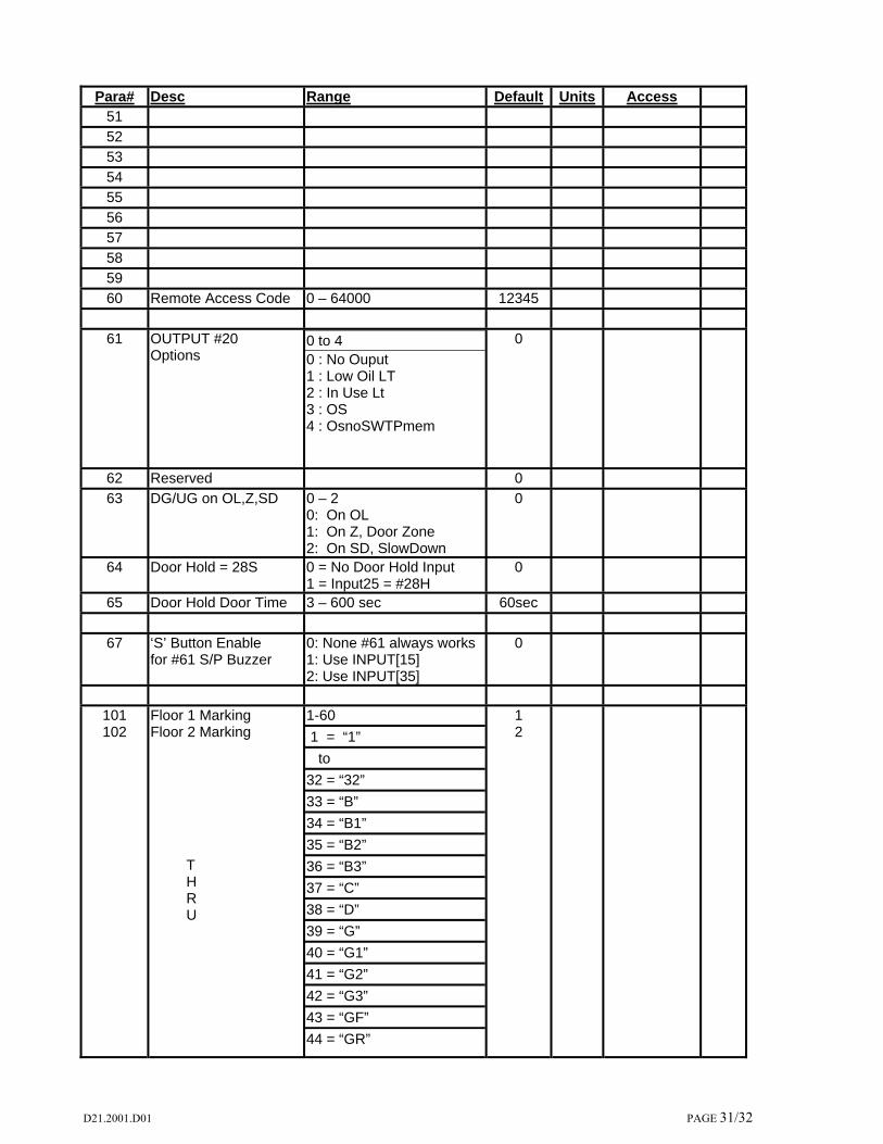
60 Remote Access Code 0 – 64000 12345
61 OUTPUT #20 Options
0 to 4 0 : No Ouput 1 : Low Oil LT 2 : In Use Lt 3 : OS 4 : OsnoSWTPmem
0
62 Reserved 0
63 DG/UG on OL,Z,SD 0 – 2 0: On OL 1: On Z, Door Zone 2: On SD, SlowDown
0
64 Door Hold = 28S 0 = No Door Hold Input 1 = Input25 = #28H
0
65 Door Hold Door Time 3 – 600 sec 60sec
67 ‘S’ Button Enable for #61 S/P Buzzer
0: None #61 always works 1: Use INPUT[15] 2: Use INPUT[35]
0
101 102
Floor 1 Marking Floor 2 Marking T H R U
1-60
1 = “1”
to
32 = “32”
33 = “B”
34 = “B1”
35 = “B2”
36 = “B3”
37 = “C”
38 = “D”
39 = “G”
40 = “G1”
41 = “G2”
42 = “G3”
43 = “GF”
44 = “GR”
1 2

D21.2001.D01 PAGE 32/32
Para# Desc Range Default Units Access
132
Floor 32 Marking
45 = “L”
46 = “L1”
47 = “L2”
48 = “L3”
49 = “LL”
50 = “M”
51 = “P”
52 = “P1”
53 = “P2”
54 = “P3”
55 = “PH”
56 = “R”
57 = “S”
58 = “SB”
59 = “T”
32
141
thru
172
Flr 1 Call Disable thru Flr 32 Call Disable
0 : All Calls Enabled 1 : Car Calls Disabled 2 : ALL CALLs Disabled For a Particular Floor
0
200 Reserved
* THIS LIST DOES NOT CONTAIN ALL PARAMETERS