essential course - 安世亚太€¦ · surface elements example ... code properties ... welcome to...
TRANSCRIPT

INTRO
Essential Course
CONTENTS
1 Introduction ...................................................................................... 10
1.1 Course Objectives .................................................................... 11
2 FEA and ANSYS with CivilFEM........................................................ 13
2.1 Finite Element Analysis ............................................................ 15
2.2 Solutions by Finite Element Method with CivilFEM .................. 20
3 ANSYS and CivilFEM Basics ........................................................... 21
3.1 Overview .................................................................................. 23
3.2 Starting ANSYS and CivilFEM ................................................. 23
Launcher ............................................................................. 24
File Management Tab ......................................................... 25
Customization/Preferences Tab .......................................... 26
High Performance Computing Setup Tab ........................... 27
Start ANSYS and CivilFEM ................................................. 28
4 The GUI ............................................................................................ 29
4.1 GUI Layout ............................................................................... 31
Graphics Window ................................................................ 33
Main Menu .......................................................................... 33
Toolbar Menu ...................................................................... 37
Icon Toolbar Menu .............................................................. 38
Raise/Hidden Icon ............................................................... 39
Input Window ...................................................................... 40
Utility Menu ......................................................................... 41
Current Settings .................................................................. 43
User Prompt Info ................................................................. 43
Output Window ................................................................... 44
Other GUI Notes ................................................................. 44
On-Line Help ....................................................................... 45
Graphics and Picking .......................................................... 47
5 CivilFEM: General Analysis Procedure ............................................ 55
5.1 Main Steps ............................................................................... 55
5.2 Example Description ................................................................ 56

5.3 Setup ........................................................................................ 57
Codes ................................................................................. 58
Units .................................................................................... 58
GUI Configuration ............................................................... 59
5.4 Preprocessing .......................................................................... 63
Materials ............................................................................. 63
Element Type ...................................................................... 65
Element Attributes ............................................................... 67
Modeling ............................................................................. 71
Save Database and Resume .............................................. 89
Create Finite Element Model .............................................. 91
Selection and Components ............................................... 104
5.5 Solution .................................................................................. 112
Types of loads................................................................... 113
Solid-Model Loads ............................................................ 113
Solid loads transference process ...................................... 114
Plot and List Loads ........................................................... 115
Solve The Model ............................................................... 123
Results File ....................................................................... 124
5.6 Postprocessing ....................................................................... 126
Types of ANSYS Postprocessor Graphics ........................ 128
CivilFEM Postprocessor .................................................... 130
6 Importing Models ............................................................................ 141
6.1 Introduction ............................................................................ 143
7 Coordinate System ......................................................................... 147
7.1 Coordinate Systems ............................................................... 149
7.2 Global Coordinate System ..................................................... 150
7.3 Local Coordinate System ....................................................... 151
7.4 Element Coordinate System ................................................... 152
7.5 Nodal Coordinate System ...................................................... 154
7.6 Results Coordinate System .................................................... 155
7.7 Display Coordinate System .................................................... 156
8 Element types ................................................................................ 157
8.1 Mesh 200 elements ................................................................ 159
8.2 Surface elements ................................................................... 160

Surface Elements Example ............................................... 165
8.3 Contact Elements ................................................................... 175
9 CivilFEM Materials ......................................................................... 177
9.1 CivilFEM and ANSYS Materials Coupling .............................. 179
9.2 Materials definition ................................................................. 180
9.3 Structural Steel Material Properties ........................................ 183
General Properties ............................................................ 183
Analysis and Design Diagrams ......................................... 184
Steel Properties ................................................................ 185
Code Properties ................................................................ 185
9.4 Concrete Material Properties .................................................. 186
General Properties ............................................................ 186
Analysis Diagram .............................................................. 187
Design Diagram ................................................................ 188
Concrete properties and code properties .......................... 188
9.5 Reinforcing Steel Material Properties ..................................... 190
9.6 User Material Library .............................................................. 191
9.7 List of Materials ...................................................................... 194
10 CivilFEM Cross Sections ................................................................ 195
10.1 Cross Section concept ........................................................... 197
10.2 Steel Cross Sections .............................................................. 197
Hot Rolled Shapes Library ................................................ 198
Steel Sections by Dimensions .......................................... 202
Steel Sections by Plates ................................................... 203
Steel Sections by Merge ................................................... 204
10.3 Concrete Cross Sections ........................................................ 206
Faces ................................................................................ 208
Concrete Reinforcement ................................................... 210
10.4 Export/Import Cross Sections ................................................. 217
Import ANSYS 2D model to CivilFEM ............................... 217
Export CivilFEM sections to ANSYS ................................. 218
10.5 User Data Base Cross Sections ............................................. 220
10.6 List of Cross Section .............................................................. 221
10.7 Cross Section Edition ............................................................. 222
10.8 Sections Modification ............................................................. 222

Section Menu .................................................................... 222
Select Menu ...................................................................... 223
Edit Menu .......................................................................... 223
10.9 Concrete Code Properties ...................................................... 229
11 Shell Vertex .................................................................................... 231
11.1 Shell Vertex Concept .............................................................. 233
11.2 Shell Reinforcement ............................................................... 234
11.3 List of Shell Vertex ................................................................. 237
12 CivilFEM Member Properties ......................................................... 239
12.1 Member Properties Concept .................................................. 241
12.2 Steel Member Properties ........................................................ 243
12.3 Concrete Member Properties ................................................. 244
13 CivilFEM Beam & Shell Properties ................................................. 245
13.1 Beam & Shell Properties and Real Constants ........................ 247
13.2 Beam & Shell Properties Definition ........................................ 248
Beam Property .................................................................. 249
Shell Property ................................................................... 249
13.3 Beam 188 and 189 elements ................................................. 252
14 CivilFEM Solid Models Analysis ..................................................... 253
14.1 Solid Section Concept ............................................................ 255
14.2 Capturing Solid Sections ........................................................ 255
15 Load Combinations ........................................................................ 257
15.1 Typical Problems .................................................................... 259
15.2 Main Applications of CivilFEM Combinations ......................... 261
15.3 General Procedure I. Obtain All possible Load Cases ........... 263
15.4 General Procedure II. Combine Results of the Whole Structure by Searching for Specific Targets ........................... 264
15.5 General Procedure III. Search for a Specific Result at a Specific Location .................................................................... 265
15.6 Define Combination Rules ...................................................... 266
Start States ....................................................................... 266
Combination Rules ............................................................ 266
15.7 Combination window .............................................................. 273
Combinations Tree ............................................................ 274
Tool Bar ............................................................................ 275
Information Window .......................................................... 275

Start States List................................................................. 276
Coefficients window .......................................................... 277
Combination Definition Process ........................................ 278
15.8 Obtain All Possible Load Cases ............................................. 280
15.9 Defining Targets ..................................................................... 281
15.10 Combine Searching for Targets ............................................. 284
15.11 Point to Combined Results ..................................................... 284
15.12 Reading Combined Results .................................................... 287
15.13 Inquiring ................................................................................. 288
15.14 Concomitance ........................................................................ 289
16 Concrete Check and Design .......................................................... 291
16.1 General Concepts .................................................................. 293
16.2 2D Axial + Bending Check ..................................................... 296
Interaction Diagram ........................................................... 298
16.3 3D Axial + Biaxial Bending Check .......................................... 299
3D Interaction Diagram ..................................................... 300
16.4 Axial + Biaxial Bending Design ............................................... 301
16.5 Shear and Torsion Check and Design .................................... 303
16.6 Cracking Check ...................................................................... 304
16.7 Shell Reinforcement Check and Design ................................. 305
16.8 Results ................................................................................... 312
17 CivilFEM Steel Checking ................................................................ 315
17.1 General concepts ................................................................... 317
17.2 Eurocode 3 ............................................................................. 318
17.3 EA-95 ..................................................................................... 321
17.4 BS 5950 ................................................................................. 321
17.5 AISC-LRFD and ASIC-ASD ................................................... 323
17.6 ANSI/AISC N690 .................................................................... 325
17.7 GB50017 ................................................................................ 326
17.8 CTE DB SE-A ......................................................................... 326
17.9 ASME BPVC Section III Div.1 SubSection NF (1989) ............ 327
18 CivilFEM Envelopes ....................................................................... 329
18.1 Alternatives and Envelopes .................................................... 331
19 CivilFEM Seismic Design ............................................................... 333
19.1 Time or Frequency Domain? .................................................. 335
19.2 Frequency Domain ................................................................. 335
19.3 What is a Spectrum? .............................................................. 336
19.4 Modal Analysis ....................................................................... 336
19.5 Seismic Design ...................................................................... 337
Modes Combination .......................................................... 341
19.6 Push Over Analysis ................................................................ 343
20 CivilFEM Further Training .............................................................. 353
20.1 Documentation ....................................................................... 355
20.2 Element Types ....................................................................... 355
20.3 Analysis Types ....................................................................... 356


CivilFEM INTRO. Essential 9
Training Manual CivilFEM INTRO Essentials
CivilFEM Release: 13.0
Published Date: March 16, 2012 Registered Trademarks: CivilFEM® is a registered trademark of Ingeciber S.A. ANSYS® is a registered trademark of ANSYS Inc. All other product names mentioned in this manual are trademarks or registered trademarks of their respective manufacturers.
Disclaimer Notice: This document has been reviewed and approved in accordance with the Ingeciber S.A. Documentation Review and Approval Procedures. “This Ingeciber S.A., software product (the Program) and program documentation (Documentation) are furnished by Ingeciber, S.A. under a CivilFEM Software License Agreement that contains provisions concerning non-disclosure, copying, length and nature of use, warranties, disclaimers and remedies, and other provisions. The program and Documentation may be used or copied only in accordance with the terms of that License Agreement.”
Copyright © 2012 Ingeciber S.A.
Proprietary Data. Unauthorized use, distribution, or duplication is prohibited.
All Rights Reserved.

CivilFEM INTRO. Essential 10
1 Introduction

1.1. Course Objectives
CivilFEM INTRO. Essential 11
1.1 Course Objectives
Welcome to the ANSYS and CivilFEM Training Course! This training course covers the basics of how to use ANSYS and CivilFEM for static analyses. It is intended for all new ANSYS and CivilFEM users. The aim of this course is to teach the basics of ANSYS and CivilFEM in the following areas:
ANSYS and CivilFEM capabilities, basic terminology and the GUI.
How to perform a complete analysis… the basic steps involved.
Building solid models and meshing.
Applying loads and solving.
Reviewing results and Postprocessing (load combinations, code checking, etc).


CivilFEM INTRO. Essential 13
2 FEA and ANSYS with CivilFEM


2.1. Finite Element Analysis
CivilFEM INTRO. Essential 15
2.1 Finite Element Analysis
2.1 Finite Element Analysis
• Finite Element Analysis is a way to simulate loading conditions on the design and determine the design’s response to those conditions.
• Design is modeled using discrete building blocks called elements.
• Each element has exact equations that describe how it responds to a certain load.
• The “sum” of the response of all elements in the model gives the total response of design.
• The elements have a finite number of unknowns, hence the name finite elements.
Historical Note
• The finite element method of structural analysis was created by academic and industrial researchers during the 1950s and 1960s.
• The underlying theory is over 100 years old and was the basis for pen-and-paper calculations in the evaluation of suspension bridges and steam boilers.
The finite element model, which has a finite number of unknowns, can only approximate the response of the physical system, which has infinite unknowns.
• So the question arises: How good is the approximation?
Physical System F.E. Model
• Unfortunately, there is no easy answer to this question. It depends entirely on what you are simulating and the tools you use for the simulation. We will, however, attempt to give you guidelines throughout this training course.
2.1. Finite Element Analysis
CivilFEM INTRO. Essential 16
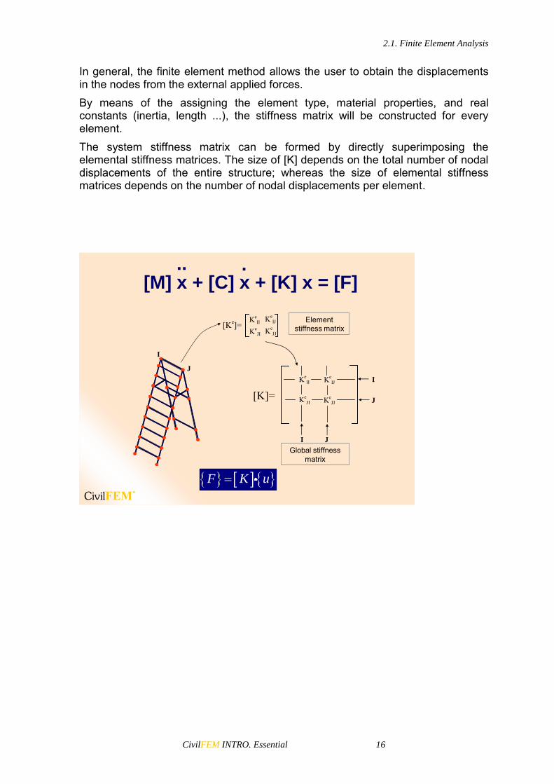
In general, the finite element method allows the user to obtain the displacements in the nodes from the external applied forces. By means of the assigning the element type, material properties, and real constants (inertia, length ...), the stiffness matrix will be constructed for every element. The system stiffness matrix can be formed by directly superimposing the elemental stiffness matrices. The size of [K] depends on the total number of nodal displacements of the entire structure; whereas the size of elemental stiffness matrices depends on the number of nodal displacements per element.
[M] x + [C] x + [K] x = [F].. .
[Ke]=Ke
II
KeJI Ke
JJ
KeIJ
I J
[K]=I
J
KeII
KeJI Ke
JJ
KeIJ
J
I
Element stiffness matrix
Global stiffness matrix
F K u

2.1. Finite Element Analysis
CivilFEM INTRO. Essential 17
To create the equations system that will describe the model’s behavior, we must assign the following information:
• Element Type– Element type to use according to the model dimensions, DOF and
analysis type.
• Real Constants and Beam and Shell Properties– Section properites which depend on element type:
Area, inertia, height...
• Material: Type and Properties– Modulus of elasticity, density,Poisson coefficient …
The selection of the element type to generate the model is an important step because it will affect the final results as well as the time of calculation of the model.
Element type:
• Degrees of Freedom Set(DOF)– Thermal element one degree of freedom: TEMP.– Estructural element six degrees of freedom : UX, UY, UZ,
ROTX, ROTY, ROTZ.
• Element Form– Hexahedron, tetrahedron, quadrilateral, triangle, line, etc.
• Dimension– 2-D.Only X-Y plane– 3-D. Line, surface or solid elements
• Kind of Displacements– Quadratic– Linear
2.1. Finite Element Analysis
CivilFEM INTRO. Essential 18
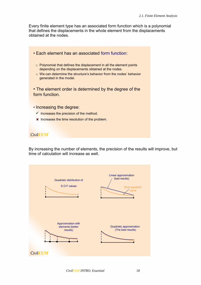
Every finite element type has an associated form function which is a polynomial that defines the displacements in the whole element from the displacements obtained at the nodes.
• Each element has an associated form function:
o Polynomial that defines the displacement in all the element points depending on the displacements obtained at the nodes.
o We can determine the structure’s behavior from the nodes’ behavior generated in the model.
• The element order is determined by the degree of the form function.
• Increasing the degree: Increases the precision of the method.
Increases the time resolution of the problem.
By increasing the number of elements, the precision of the results will improve, but time of calculation will increase as well.
Quadratic distribution of
D.O.F values Real quadratic curve
Linear approximation (bad results)
Approximation with elements (better
results)Quadratic approximation
(The best results)
2.1. Finite Element Analysis
CivilFEM INTRO. Essential 19
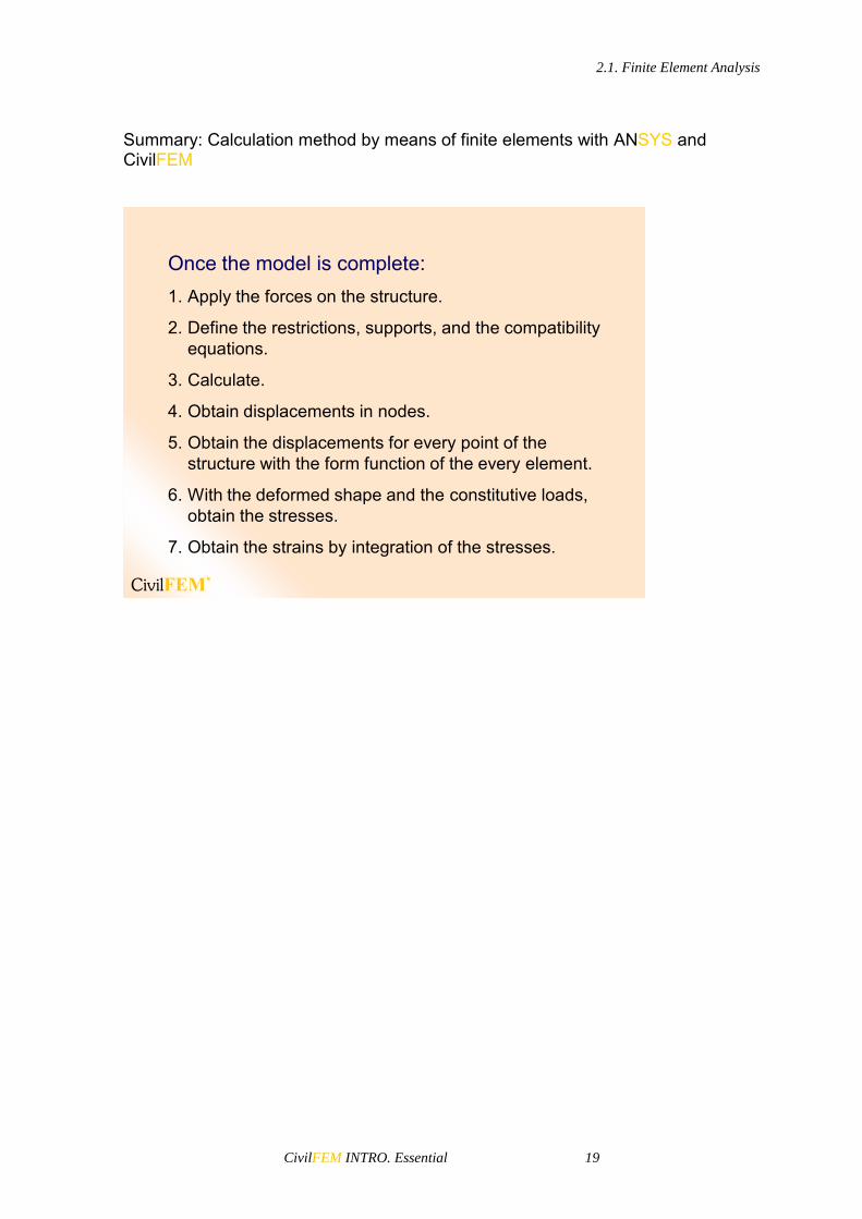
Summary: Calculation method by means of finite elements with ANSYS and CivilFEM
Once the model is complete:1. Apply the forces on the structure.
2. Define the restrictions, supports, and the compatibility equations.
3. Calculate.
4. Obtain displacements in nodes.
5. Obtain the displacements for every point of the structure with the form function of the every element.
6. With the deformed shape and the constitutive loads, obtain the stresses.
7. Obtain the strains by integration of the stresses.
2.2. Solutions by Finite Element Method with CivilFEM
CivilFEM INTRO. Essential 20
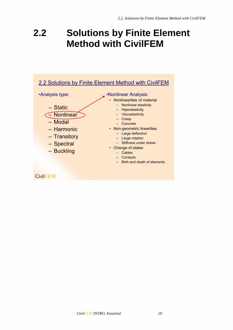
2.2 Solutions by Finite Element Method with CivilFEM
2.2 Solutions by Finite Element Method with CivilFEM
•Analysis type:
– Static– Nonlinear– Modal– Harmonic– Transitory– Spectral– Buckling
•Nonlinear Analysis:• Nonlinearities of material
– Nonlinear elasticity– Hiperelasticity– Viscoelasticity– Creep– Concrete
• Non-geometric linearities– Large deflection– Large rotation– Stiffness under stress
• Change of states– Cables– Contacts– Birth and death of elements

CivilFEM INTRO. Essential 21
3 ANSYS and CivilFEM Basics


3.1. Overview
CivilFEM INTRO. Essential 23
3.1 Overview
The ANSYS and CivilFEM program can be run in an interactive mode or a batch mode. In the interactive mode (default mode), you can exchange information with the computer continuously. You can execute a command by selecting its menu path in the GUI or by typing it directly. The ANSYS and CivilFEM program processes the command in real time. Interactive mode allows you to use the GUI, online help, and other various tools to create the engineering model in the graphics window and modify it as you work through the analysis. In batch mode, you submit a file of commands to the ANSYS and CivilFEM program. This command file may have been generated by a previous ANSYS and CivilFEM session, by another program, or by creating a command file with an editor. On some operating systems, you can run a batch job in the background while completing other tasks on the computer. Batch mode is useful when you do not need to interact with the program, such as during the solution phase of an analysis.
3.1 Overview
Two ways of working with ANSYS and CivilFEM: Interactive and Batch Modes
• Interactive mode allows you to interact “live” with the program, reviewing each operation as you go.
– Of the three main phases of an analysis — preprocessing, solution, and postprocessing — the preprocessing and postprocessing phases are best suited for interactive mode.
• Batch mode allows you to submit a batch file of commands which ANSYS and CivilFEM process in the background.
• We will mainly cover interactive mode in this course.
3.2 Starting ANSYS and CivilFEM
From the Windows Start Menu, select the CivilFEM program’s group and then use the ANSYS + CivilFEM entry to run the ANSYS and CivilFEM program with previously selected program settings. To modify these settings, use the Product Launcher.

3.2. Starting ANSYS and CivilFEM
CivilFEM INTRO. Essential 24
3.2 Starting CivilFEM
Launcher –Allows you to start CivilFEM and other CivilFEM utilities by pressing buttons on a menu.
• The Product Launcher brings up a dialog box containing start-up options:
Start > Programs > CivilFEM XX*
(*) XX is the number of the version
From the ANSYS or CivilFEM Start Menu, you can select other options in addition to the launcher:
Utilities (administration, animate, …)
Help
CivilFEM Internet Update Use the Product Launcher to select product settings, such as the simulation environment, the specific license, or any add-on modules or analysis type you want to run. Based on your product selection, you can then specify file management, customization/preferences, and solver setup options. Product settings and options under each tab are explained below. All options may not be displayed, depending on your product selection.
Launcher
Here, specify your simulation environment, license, and add-on modules. The simulation environment allows the user to choose an interactive interface or to start a batch run. Options include:
ANSYS Workbench
ANSYS
ANSYS Batch

3.2. Starting ANSYS and CivilFEM
CivilFEM INTRO. Essential 25
MFX - ANSYS/CFX
LS-DYNA Solver Depending on which environment you select and what licenses are available, the product selection choices or options under the following tabs may vary. CivilFEM is only available in the ANSYS environment. In the License field, select a license from the available types. Only those licenses that are both available at your site and valid with the simulation environment selected will be shown.
Launcher has a combo menu used to select the Simulation Environment (select ANSYSEnvironment) in the top of the window .
Available licenses and add-on modules can be selected here.
Other tabs below include: File Management, Customization/Preferences, and High Performance Computing Setup.
File Management Tab
This tab contains the information necessary to manage your files, such as the location of your working directory and job name. The available options will differ depending on the simulation environment you selected. If you selected the ANSYS simulation environment, you can specify:
Working directory: Sets the directory in which the ANSYS and CivilFEM run will be executed
Job Name: Defines the base filename used for all files generated by the ANSYS and CivilFEM run.
If you selected the ANSYS Batch simulation environment, you can specify the above items as well as the following:
Input file: Specifies the file of ANSYS and CivilFEM commands you are submitting for batch execution

3.2. Starting ANSYS and CivilFEM
CivilFEM INTRO. Essential 26
Output file: Specifies the file to which ANSYS and CivilFEM directs text output by the program
Include input listing in output: Includes or excludes the input file listing at the beginning of the output file
• File Management Tab - used to specify the Working Directory (Where all of your files will reside) and a Job Name of your choosing.
Customization/Preferences Tab
The options under this tab allow you to specify detailed settings about your working environment, such as memory settings, parallel/distributed processing settings, custom executables, and additional parameters. The available options will differ depending on the simulation environment you selected on the first tab.
3.2. Starting ANSYS and CivilFEM
CivilFEM INTRO. Essential 27
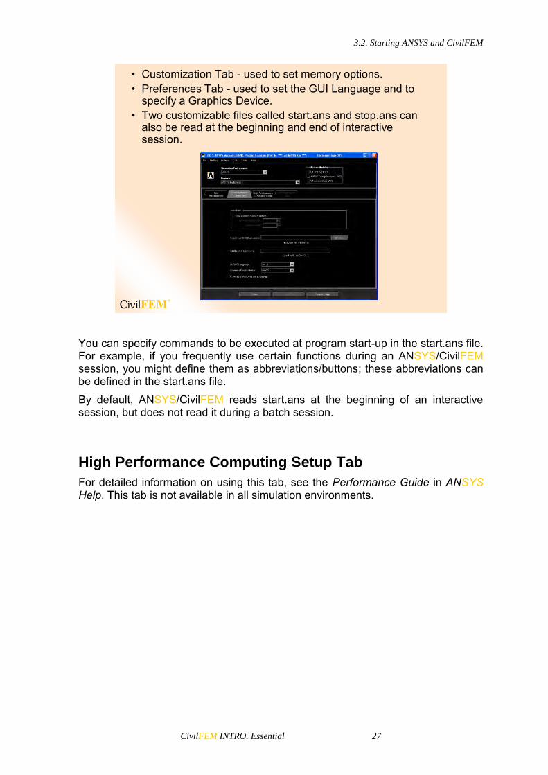
• Customization Tab - used to set memory options.• Preferences Tab - used to set the GUI Language and to
specify a Graphics Device.• Two customizable files called start.ans and stop.ans can
also be read at the beginning and end of interactive session.
You can specify commands to be executed at program start-up in the start.ans file. For example, if you frequently use certain functions during an ANSYS/CivilFEM session, you might define them as abbreviations/buttons; these abbreviations can be defined in the start.ans file. By default, ANSYS/CivilFEM reads start.ans at the beginning of an interactive session, but does not read it during a batch session.
High Performance Computing Setup Tab
For detailed information on using this tab, see the Performance Guide in ANSYS Help. This tab is not available in all simulation environments.

3.2. Starting ANSYS and CivilFEM
CivilFEM INTRO. Essential 28
Advanced options for distributed solvers can be selected in the last tab.
Start ANSYS and CivilFEM
After choosing the desired start-up options, press the Run button to start CivilFEM.
Start CivilFEM

CivilFEM INTRO. Essential 29
4 The GUI


4.1. GUI Layout
CivilFEM INTRO. Essential 31
4.1 GUI Layout
You use the GUI to communicate with ANSYS and CivilFEM interactively. Each GUI interaction produces ANSYS and CivilFEM commands to perform the operation. Most of the tasks used in ANSYS and CivilFEM can be performed either interactively or by inputting the appropriate commands. The GUI allows you to perform an analysis with little or no knowledge of the ANSYS and CivilFEM commands, while still adhering to the command level operations.
4.1 GUI Layout
Output Window
Abbreviation Toolbar Menu
Graphics Area
Main Menu
Input Line
Current SettingsUser Prompt Info
Raise/Hidden Icon
Contact Manager Icon
Model Control Toolbar
Icon Toolbar Menu
Utility Menu
4.1. GUI Layout
CivilFEM INTRO. Essential 32
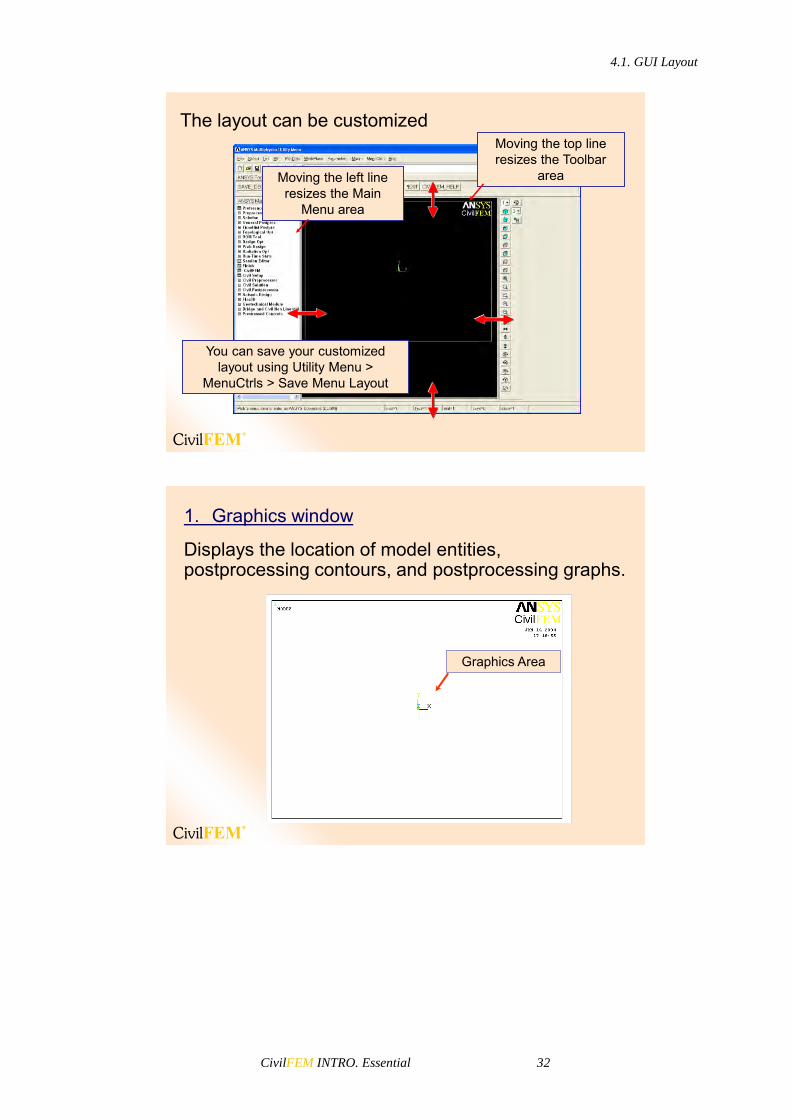
The layout can be customizedMoving the top line resizes the Toolbar
areaMoving the left line resizes the Main
Menu area
You can save your customized layout using Utility Menu >
MenuCtrls > Save Menu Layout
1. Graphics window
Displays the location of model entities, postprocessing contours, and postprocessing graphs.
Graphics Area

4.1. GUI Layout
CivilFEM INTRO. Essential 33
Graphics Window
1. Graphics window
Displays the location of model entities, postprocessing contours, and postprocessing graphs.
Graphics Area
This window is where graphics displays are plotted. It is usually the largest of the GUI windows.
The Capture Image function (Capture Image button in the Standard Toolbar or Utility Menu> PlotCtrls> Capture Image) allows you to create “snapshots” of the Graphics Window. After an image is captured you can save it to a file and then restore it in any ANSYS and CivilFEM session. Captured images are useful for comparing different views, sets of results, or other significant images simultaneously on the screen.
Click the right mouse button to access many functions that can adjust the Graphics Window display. The available information will vary according to the type of display and the position of the cursor in the window. Along with some of the standard Pan-Zoom-Rotate functions, you can also access many of the window control functions in the PlotCtrls section of the Utility Menu.
Main Menu
The Main Menu is where you begin your analysis. It contains the ANSYS and CivilFEM analysis functions you use to create your model and perform the analysis. The Main Menu is arranged in a tree structure. This structure makes progressive submenus accessible as you proceed through the steps of the analysis. Each menu topic in the Main Menu either expands to show more menu

4.1. GUI Layout
CivilFEM INTRO. Essential 34
options (indicated by a boxed +) or performs an action (indicated by an icon preceding the menu topic).
2. Main Menu
• The main menu is made up of two parts: General Purpose part and Specific Civil Engineering part.
• Tree structure format.
• Contains the main functions required for an analysis.
• Use scroll bar to gain access to long tree structures.
Scroll bar
Civil part
General part
• Expand All optionPosition mouse cursor on branch of Main Menu – then select right mouse button
The option to expand the branch is displayed
Selecting “Expand All” expands the branch contents

4.1. GUI Layout
CivilFEM INTRO. Essential 35
You can set your menus to automatically collapse and expand your subtopics. Use the “Collapse Siblings” feature (found in the right mouse click menu) to set your menu expansion preferences. When you choose collapse, the subtopics you have open automatically collapse when you choose another main topic.
• Expand Headings and Collapse Sibling
Right Click in Main Menu and select “Preferences”.
Level color, filtering and expansion of Main Menu can be changed.
You use the same right mouse click context-sensitive control to configure the main menu for selectable contrasting color display within each nested level. You can designate any color for the menu text at each level, making the transition between levels easily detectable.

4.1. GUI Layout
CivilFEM INTRO. Essential 36
With “Expand headings” and “Collapse siblings” behavior active …
Creating a Volume branch open
When the Delete branch is opened, the Create branch is closed
Note, inactivate “Collapse siblings” to keep open the Create branch
• Filtered Branches
Main Menu with structural and thermal element type defined
Main Menu with only thermal element type defined
Only “Apply” branches shown are those for defined element types
One of the most useful customizations you can perform from the GUI is to apply filtering to your menu choices. Filtering lets you grey out, or completely hide many of the functions that will not be needed during your analysis. The preferences dialog box is used to adjust filtering.

4.1. GUI Layout
CivilFEM INTRO. Essential 37
Toolbar Menu
The Toolbar Menu is a convenient area where you can add push-buttons for command, function, and macro shortcuts. These push buttons execute commonly used ANSYS and CivilFEM functions.
3. Toolbar Menu
• Contains abbreviations – short-cuts to commonly used commands and functions.
• You can create your own “button menu” system, but it requires knowledge of ANSYS and CivilFEMcommands.
You can create abbreviations either through the *ABBR command or through the Utility Menu> Macro> Edit Abbreviations or Utility Menu> MenuCtrls> Edit Toolbar menu items. Using one of the menu items is preferable for two reasons:
Clicking OK automatically updates the toolbar (using the *ABBR command requires that you use the Utility Menu> MenuCtrls> Update Toolbar menu item to make your new abbreviation appear on the toolbar).
You can easily edit the abbreviation if required. Toolbar buttons are not consistent from one ANSYS and CivilFEM session to the next; however, they are saved and maintained in the database so that any "resume" of the session will still contain these abbreviations. To save your custom button definitions, you must explicitly save them to a file through the Utility Menu> MenuCtrls> Save Toolbar menu item (ABBSAV command) and restore them for each session using the Utility Menu> MenuCtrls> Restore Toolbar menu item (ABBRES command).

4.1. GUI Layout
CivilFEM INTRO. Essential 38
Icon Toolbar Menu
When you begin your ANSYS and CivilFEM session, the start-up routine reads a number of text files and scripts that set parameters and conditions for your ANSYS and CivilFEM session. Many of these files can be modified to provide a more customized level of operation. The start.ans file is one such file. You call up toolbars, set their position and define their content in a similar fashion. You can list the toolbars in the tlbrlistXXX.ans file (where XXX is the ANSYS and CivilFEM version number). This file contains a list of the toolbars activated at start up. The toolbar filenames are designated as *.TLB files, and each file in the list contains the specifications for the content, appearance, and position of the toolbars in the ANSYS GUI. You can add additional toolbars to the GUI (including a Pan-Zoom-Rotate functionality button bar, ANSYSGRAPHICAL.TLB, that is included with the program) by creating the corresponding *.TLB files and including them in the tlbrlistXXX.ans file. The default tlbrlistXXX.ans file loads the Standard Toolbar by calling the file \ANSYSSTANDARD.TLB and the ANSYS Toolbar by calling the file \ANSYSABBR.TLB. These files should be placed in the same directory as your tlbrlistXXX.ans file, although the files themselves can be placed anywhere as long as the proper path string is designated and remains valid. For more information about creating a toolbar file you can see the chapter 4.3.8 of the Operations Guide in the ANSYS help documentation.
4. Icon Toolbar Menu
• Contains icons of commonly used functions.
• Can be customized by the user. (i.e. adding icons, additional toolbars)
Pan-Zoom-Rotate
New Analysis
Open ANSYS File
Save Analysis
ANSYS Help
Image Capture
Report Generator
The standard buttons and their functions include:
4.1. GUI Layout
CivilFEM INTRO. Essential 39
New Analysis: Saves and clears information for the existing analysis and starts a new analysis.
Open ANSYS and CivilFEM File: Opens ANSYS and CivilFEM database or input files to be read into ANSYS and CivilFEM. The file type determines the operation.
Save Analysis: Saves the current analysis to a database file.
Pan-Zoom-Rotate: Opens the Pan-Zoom-Rotate dialog box.
Image Capture: Opens the image capture GUI.
Report Generator: Opens the report generator GUI.
ANSYS Help: Displays the table of contents for the ANSYS HTML-based help.
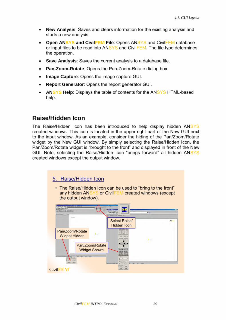
Raise/Hidden Icon
The Raise/Hidden Icon has been introduced to help display hidden ANSYS created windows. This icon is located in the upper right part of the New GUI next to the input window. As an example, consider the hiding of the Pan/Zoom/Rotate widget by the New GUI window. By simply selecting the Raise/Hidden Icon, the Pan/Zoom/Rotate widget is “brought to the front” and displayed in front of the New GUI. Note, selecting the Raise/Hidden Icon “brings forward” all hidden ANSYS created windows except the output window.
5. Raise/Hidden Icon
• The Raise/Hidden Icon can be used to “bring to the front” any hidden ANSYS or CivilFEM created windows (except the output window).
Pan/Zoom/Rotate Widget Hidden
Pan/Zoom/Rotate Widget Shown
Select Raise/ Hidden Icon

4.1. GUI Layout
CivilFEM INTRO. Essential 40
Input Window
You use the Input Window to conveniently enter single commands and access the history buffer without changing the overall configuration of the GUI
6. Input Window• Allows you to enter commands. (All GUI functions actually
“send” commands to ANSYS and CivilFEM. If you know these commands, you can type them in the Input Window).
• Command format is dynamically displayed until user finishes entering the command.
As a command is typed, the format of the command is dynamically displayed
As you enter commands into the Input Window, the dynamic command help appears in a box above the window. As you type the letters, the command help displays the possible commands and guides you through the proper spelling and syntax of the command. You can view and access the history buffer by clicking the down arrow on the right of the text entry box. A drop down list containing the entry history appears. Clicking the left mouse button on any line in the history buffer moves that line to the text entry box where you can edit and execute it. A double click on any line in the history buffer automatically executes that line.
The vertical scroll bar at the right corner of the history buffer box allows you to scroll through the history buffer. You can also use the up and down arrow keys to navigate the history buffer.
4.1. GUI Layout
CivilFEM INTRO. Essential 41
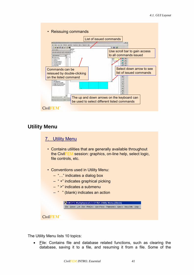
• Reissuing commands
Select down arrow to see list of issued commands
List of issued commands
Use scroll bar to gain access to all commands issued
The up and down arrows on the keyboard can be used to select different listed commands
Commands can be reissued by double-clicking on the listed command
Utility Menu
7. Utility Menu
• Contains utilities that are generally available throughout the CivilFEM session: graphics, on-line help, select logic, file controls, etc.
• Conventions used in Utility Menu:– “…” indicates a dialog box– “ +” indicates graphical picking– “ >” indicates a submenu– “ ” (blank) indicates an action
The Utility Menu lists 10 topics:
File: Contains file and database related functions, such as clearing the database, saving it to a file, and resuming it from a file. Some of the

4.1. GUI Layout
CivilFEM INTRO. Essential 42
functions under the File menu are valid at Begin level only. If you choose such a function when you are not at Begin level, you will see a dialog box giving you a choice of moving to Begin level and executing the function or cancelling the function.
Select: Includes functions that allow you to select subsets of entities and to create components.
List: Enables you to list virtually any data item stored in the ANSYS and CivilFEM database. You can also obtain status information about different areas of the program and list the contents of files residing on your system.
Plot: Lets you plot keypoints, lines, areas, volumes, nodes, elements, and other data that can be graphically displayed.
PlotCtrls: Includes functions which control the view, style, and other characteristics of graphics displays. The Hard Copy function lets you obtain hard copies of the entire screen or just the Graphics Window.
WorkPlane: Enables you to toggle the working plane on or off and to move, rotate, and otherwise manoeuvre the working plane. You can also create, delete, and switch coordinate systems by using this menu.
Parameters: Includes functions to define, edit, and delete scalar and array parameters.
Macro: Allows you to execute macros and data blocks. You can also create, edit, and delete abbreviations, which appear as push buttons on the Toolbar.
MenuCtrls: Lets you create, edit, and delete abbreviations on the ANSYS and CivilFEM Toolbar and modify the colors and fonts used in the GUI display. Once you've adjusted the GUI to your liking, you can use the Save Menu Layout function to save the current GUI configuration.
Help: Brings up the ANSYS Help System.

4.1. GUI Layout
CivilFEM INTRO. Essential 43
Current Settings
8. Current Settings• The current element attributes settings and currently active
coordinate system are displayed at the bottom on the GUI.
Element Attributes
Active Coordinate System
User Prompt Info
9. User Prompt Info
• Instructions to the user are displayed in the lower left hand area of the GUI. The user will be given user prompt info for operations, such as picking operations.
User Prompt Info

4.1. GUI Layout
CivilFEM INTRO. Essential 44
Output Window
The Output window receives all text output from the program - command responses, notes, warnings, errors, and any other messages. It is usually positioned behind the GUI, but you can raise it to the front when necessary.
10. Output Window
• The output window gives the user feedback on how ANSYS and CivilFEM interpreted the user’s input.
• The Output Window is independent of the menus. Caution: Closing the output window closes the entire CivilFEM session!
Able to verify the version
Other GUI Notes
11. Other GUI Notes
• Some dialog boxes have both Apply and OK buttons.– Apply applies the dialog settings, but retains (does not
close) the dialog box for repeated use.– OK applies the dialog settings and closes the dialog
box.
• Remember that you are not restricted to using the menus. If you know the command, feel free to enter it in the Input Window!
• The output window is not affected by the Raise/Hidden Button. For convenience, the user may want to resize the GUI, so part of the output window is displayed to allow easy access.

4.1. GUI Layout
CivilFEM INTRO. Essential 45
On-Line Help
12. On-Line Help
• CivilFEM has a documentation system which provides extensive on-line help.
• You can get help on:– ANSYS commands– CivilFEM commands– Element types– Analysis procedures– Special GUI “widgets” such as Pan-Zoom-Rotate
• There are several ways to start the ANSYS or CivilFEMhelp system:
– Launcher > Product Help– Utility Menu > Help > Help Topics– From windows, Start > Programs > ANSYS > Help – From windows, Start > Programs > CivilFEM > Help – Any dialog box > Help– Type HELP,name in the Input Window. Name is a
command or element name.
• An ANSYS dialog box or command is for ANSYS help and a CivilFEM dialog box or command is used for CivilFEMhelp.
As you scan a page of text in the navigation window, you will notice certain words or phrases are underlined and appear in a different color. These items are hypertext links. A hypertext link is a text navigation tool that, when clicked, shows

4.1. GUI Layout
CivilFEM INTRO. Essential 46
information about that item. Typical items which appear as hypertext links are command names, element types, and manual section references.
• ExampleANSYS help
CivilFEM help
Press help
Press help
Or press: Help,K
Or press: Help,~CFMP
Press Alt+126 to write this
symbol
• Pressing the Product Help button on the launcher brings up a help browser with:
– a navigational window containing Table of Contents, Index, Search Utility and Favorites.
– a document window containing the help information.

4.1. GUI Layout
CivilFEM INTRO. Essential 47
• Use the Contents tab to browse to the item of interest.
• Use the Index tab to quickly locate specific commands, terminology, concepts, etc.
• Use the Search tab to query the entire help system for specific words or phrases.
• ANSYS also provides an on-line tutorial.
• The tutorial consists of detailed instructions for a set of problems solved in ANSYS.
• To access the tutorial, click on Utility Menu > Help > ANSYS Tutorials
Graphics and Picking
Many functions in the ANSYS program involve graphical picking - using the mouse to identify model entities and coordinate locations.
4.1. GUI Layout
CivilFEM INTRO. Essential 48
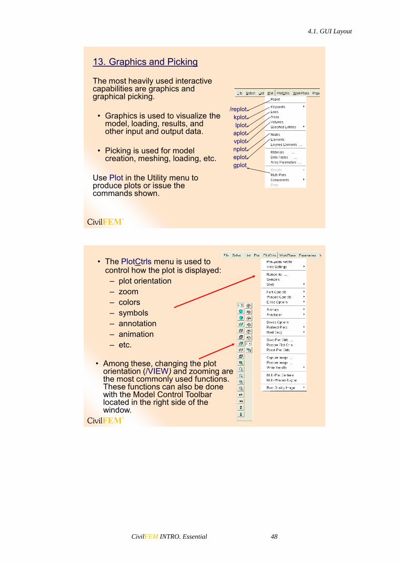
13. Graphics and Picking
The most heavily used interactive capabilities are graphics and graphical picking.
• Graphics is used to visualize the model, loading, results, and other input and output data.
• Picking is used for model creation, meshing, loading, etc.
Use Plot in the Utility menu to produce plots or issue the commands shown.
/replotkplotlplot
aplotvplotnploteplotgplot
• The PlotCtrls menu is used to control how the plot is displayed:
– plot orientation– zoom– colors– symbols– annotation– animation– etc.
• Among these, changing the plot orientation (/VIEW) and zooming are the most commonly used functions. These functions can also be done with the Model Control Toolbar located in the right side of the window.

4.1. GUI Layout
CivilFEM INTRO. Essential 49
• The default view for a model is the front view: looking down the +Z axis of the model.
• To change it, use dynamic mode — a way to orient the plot dynamically using the Control key and mouse buttons or picking in the Model Control Toolbar
– Ctrl + Left mouse button pans the model.
– Ctrl + Middle mouse button:zooms the modelspins the model (about screen Z)
– Ctrl + Right mouse button rotatesthe model:
about screen Xabout screen Y
Note, the Shift-Right button on a two-button mouse is equivalent to the Middle mouse button on a three-button mouse.
P Z RCtrl
• You also can use the Dynamic Mode setting in the Pan-Zoom-Rotate dialog box.
– The same mouse button assignments apply.
– On 3-D graphics devices, you can also dynamically orient the light source. This is useful for different light source shading effects.
When using 3-D driver

4.1. GUI Layout
CivilFEM INTRO. Essential 50
• Other functions in the Pan-Zoom-Rotate dialog box:
– Preset views– Zoom-in on specific
regions of the model– Pan, zoom, or rotate in
discrete increments (as specified by the Rate slider)
• Rotation is about the screen X, Y, Z coordinates.
– Fit the plot to the window
– Reset everything to default
Front +Z view, from (0,0,1)Back -Z view (0,0,-1)Top +Y view (0,1,0)Bot -Y view (0,-1,0)Right +X view (1,0,0)Left -X view (-1,0,0)Iso Isometric (1,1,1)Obliq Oblique (1,2,3)WP Working plane view
Zoom By picking center of a square
Box Zoom By picking two corners of a box
Win Zoom Same as Box Zoom, but box is proportional to window.
Back Up “Unzoom” to previous zoom.
Picking• Picking allows you to identify model
entities or locations by clicking in the Graphics Window.
• A picking operation typically involves the use of the mouse and a picker menu. It is shown by a + sign on the menu.
• For example, you can create keypoints by picking locations in the Graphics Window and then pressing OK in the picker.

4.1. GUI Layout
CivilFEM INTRO. Essential 51
Two types of picking:
• Retrieval picking:– Picking existing entities for a
subsequent operation.– Allows you to enter entity numbers
in the Picker Window. To do this, press ENTER before Apply or OK, if you don’t do so the program does not pick or unpick any entity.
– Use the Pick All button to indicate all entities.
• Locational picking:– Locating coordinates of a point,
such as a keypoint or node.– Allows you to enter coordinates in
the Picker Window.
Example ofLocational
Picker
Example ofRetrieval
Picker
Whenever you use graphical picking (that is, when you click on a menu topic ending with the + symbol), the GUI brings up a picking menu, sometimes known as the picker.
Function Title [1]. Identifies the function being performed.
Pick Mode [2]. Allows you to pick or unpick a location or entity For retrieval picking, you also can choose among single, box, polygon, circle, and loop mode. In single pick mode, each click on the mouse picks one entity. With box, polygon, and circle modes, press and drag the mouse to enclose a set of

4.1. GUI Layout
CivilFEM INTRO. Essential 52
entities in a box, polygon, or circle. Loop mode is available for picking lines and areas only.
Pick Status [3]. Shows the number of items picked ("Count") and the minimum and maximum number of picks required for the function.
Picked Data [4]. Shows information about the item being picked. For locational picking, the working plane and global Cartesian coordinates of the point are shown. For retrieval picking, this area shows the entity number.
Keyboard Entry Options [5]. In some cases, you may need to enter the required data by keyboard in the picker. For example, to specify a known coordinate location during locational picking, it may be easier to enter the coordinates than to use the mouse. In that case, you can choose between working plane coordinates and global Cartesian coordinates. For retrieval picking, you can choose between entering a list of entity numbers and a range of numbers.
Action Buttons [6]. This area of the menu contains buttons that take action on the picked entities, as follows:
- OK: Applies the picked items to execute the function and closes the picking menu.
- Apply: Applies the picked items to execute the function but does not close the picking menu.
- Reset: Unpicks all picked entities and restores the menu and the graphics area to their state at the last Apply.
- Cancel: Cancels the function and closes the picking menu. - Pick All: Picks all entities, executes the selected function, and closes
the picking menu. This feature is available for retrieval picking only. - Help: Brings up help information for the function being performed.
4.1. GUI Layout
CivilFEM INTRO. Essential 53
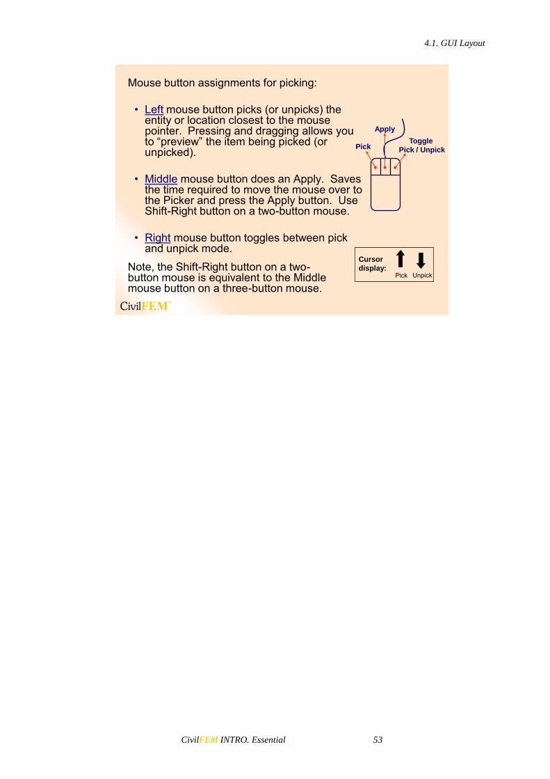
Mouse button assignments for picking:
• Left mouse button picks (or unpicks) the entity or location closest to the mouse pointer. Pressing and dragging allows you to “preview” the item being picked (or unpicked).
• Middle mouse button does an Apply. Saves the time required to move the mouse over to the Picker and press the Apply button. Use Shift-Right button on a two-button mouse.
• Right mouse button toggles between pick and unpick mode.
Pick
Apply
Toggle
Pick / Unpick
UnpickPick
Cursor
display:Note, the Shift-Right button on a two-button mouse is equivalent to the Middle mouse button on a three-button mouse.


CivilFEM INTRO. Essential 55
5 CivilFEM: General Analysis Procedure
5.1 Main Steps
Regardless of the physics of the problem, the same general procedure can always be followed to run a simulation. A sample model will be used to demonstrate the general analysis procedure.
Every analysis involves four main steps:• Preliminary Decisions
– Which analysis type?– What to model?– Which element type?– Select active code and units.
• Preprocessing– Define Element properties (materials,
sections…).– Create or import the model geometry.– Mesh the geometry.
• Solution– Apply loads and boundary conditions.– Solve.
• Postprocessing– Do combinations.– Review results.– Check the validity of the solution.– Code checking or design.
Preprocessing
Solution
Postprocessing
Preliminary Decisions
5.1 Main steps
5.2. Example Description
CivilFEM INTRO. Essential 56
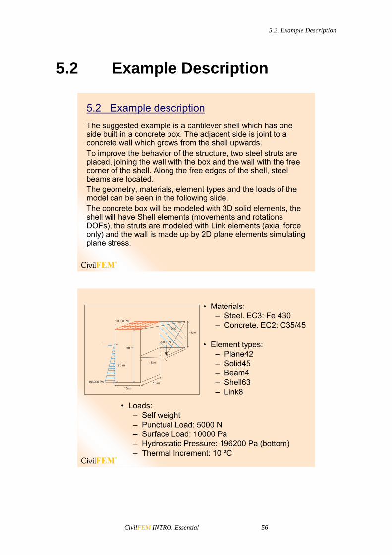
5.2 Example Description
The suggested example is a cantilever shell which has one side built in a concrete box. The adjacent side is joint to a concrete wall which grows from the shell upwards.To improve the behavior of the structure, two steel struts are placed, joining the wall with the box and the wall with the free corner of the shell. Along the free edges of the shell, steel beams are located.The geometry, materials, element types and the loads of the model can be seen in the following slide.The concrete box will be modeled with 3D solid elements, the shell will have Shell elements (movements and rotations DOFs), the struts are modeled with Link elements (axial force only) and the wall is made up by 2D plane elements simulating plane stress.
5.2 Example description
• Materials:– Steel. EC3: Fe 430– Concrete. EC2: C35/45
• Element types:– Plane42– Solid45– Beam4– Shell63– Link8
• Loads:– Self weight– Punctual Load: 5000 N– Surface Load: 10000 Pa– Hydrostatic Pressure: 196200 Pa (bottom)– Thermal Increment: 10 ºC
5000 N
10000 Pa
º10 C
30 m
15 m
15 m
15 m
15 m
20 m
196200 Pa

5.3. Setup
CivilFEM INTRO. Essential 57
5.3 Setup
5.3 SETUP• The first step when working with CivilFEM is to choose the
active codes and units.
• Once you have chosen the units system and have begun your work with CivilFEM, you cannot change the active units system.
• Remember then to introduce all the data values in the active units system at the beginning!
CivilFEM converts all the section dimensions available in the library (including the user cross section library), the active code formulation, etc. to the active units. However, it is important to note that CivilFEM can do this conversion only as a first step.

5.3. Setup
CivilFEM INTRO. Essential 58
Codes
Select:• Code for Steel Checking• Code for Concrete Checking (concrete and
reinforced concrete)• Code for Prestressed Concrete• Code for Seismic Design
Units and Code must be selected first and should not be changed later on
Codes
Steel, reinforced concrete, prestressed concrete and seismic codes can be selected in this window. By default the Eurocodes are shown. See ~CODESEL command.
Units
Select:• Length unit• Time unit• Force, or Pressure/Stress or Mass unit (left
as “User” the other two of them).
If a units system is not available in the library, you may use it by defining the conversion factor to international system.
Units

5.3. Setup
CivilFEM INTRO. Essential 59
The units system for all of the calculations is selected in this window. By default, CivilFEM uses the International System (SI). Given that the units are related, only 3 of them may be personalised and the rest are automatically calculated. Results data are given in the corresponding units, and abbreviations must be specified in the second column (in the example: mm, s, kN, uuP, uuM). See ~UNITS command.
GUI Configuration
This tab includes graphical options, interface configurations, background colors, and the following options:
– Title color and title shadow: These buttons change the title and shadow color for all the GUI.
– Undo/Redo steps: this number shows the Undo/redo steps available. (When this option is chosen, it is necessary to take into account the memory of the computer and the data base size used).
GUI Configuration

5.3. Setup
CivilFEM INTRO. Essential 60
– Data table decimals: Number of decimal places used in the CivilFEM editors.
– Auto-Fit: Fit the objects in the CivilFEM Graphical windows.
– Dynamic size axis or Fixed size axis: Option to show the dynamic axis or fixed axis in the CivilFEM editors.
– Optimize log: This option removes the redundant commands produced when the CivilFEM GUI is used.
– Zoom Box: Zone utilized when performing a zoom operation. This can be an inner rectangle selected by the mouse, a bounding rectangle constrained by the graphics area window, or both.
– Tab Views: The different views for the tabs of the editors are up, down, or the operating system default.
The CivilFEM setup window also includes other tabs such as: CF config, Bridges config, Geotechnical config and Prestressed config. CF CONFIG
In this section diverse configuration parameters are determined.

5.3. Setup
CivilFEM INTRO. Essential 61
Strength Reduction Factor
o Strength reduction factor used for different reinforced concrete codes or standards.
Concrete Interaction Diagram Parameters o NED: Number of steps on strains. o NTD: Number of steps on angles. o N2D: Number of steps on 2D analysis. o WMIN: Minimum reinforcement factor. o WMAX: Maximum reinforcement factor. o DELTA: Coefficient to establish the diagram’s centre position. o LIMCOUNT: Maximum number of iterations on design. o NMAXDIAG: Maximum number of diagrams stored in file.
CivilFEM Result File o RESMAX: Maximum number of records in CivilFEM results file.
Shell Result o PLOT: ANSYS result used for plotting CivilFEM shell results. o FORCES AND MOMENTS: How CivilFEM obtains results on shell
elements:

5.3. Setup
CivilFEM INTRO. Essential 62
ANSYS Centroid values. Forces and moments are obtained at the centroid of the element and are considered constant for the entire element.
CivilFEM node values. CivilFEM calculates the values of forces and moments at each node of the element.
BRIDGES CONFIG
Bridge configuration parameters. This tab only appears if the Bridge and Civil Non Linearities Module is activated.
GEOTECHNICAL CONFIG
Geotechnical Module parameters. This tab only appears if the Geotechnical Module is activated.
PRESTRESSED CONCRETE CONFIG
Prestressed Concrete Module parameters. This tab only appears if the Advanced Prestressed Concrete Module is activated.

5.4. Preprocessing
CivilFEM INTRO. Essential 63
5.4 Preprocessing
Materials
Material properties defined by CivilFEM include ANSYS standard properties as well as other properties necessary for CivilFEM specific calculations, such as properties related to codes: characteristic strengths, yield strengths, reduction coefficients, etc.
5.4 PRE-PROCESSING
• Once you have chosen the units system and the active code, select the materials that will be used.
Materials
In the CivilFEM’s materials window the user may find a list of the materials currently defined in the database. It is possible to choose any of the different materials CivilFEM has in its library. When defining a material with CivilFEM, ANSYS standard properties are defined by assigning ANSYS materials the same numbering as CivilFEM materials. It is not recommended to directly modify material properties with ANSYS, as CivilFEM may later change those properties automatically to coordinate with ones specified in the database, to update time dependent properties, etc.
5.4. Preprocessing
CivilFEM INTRO. Essential 64
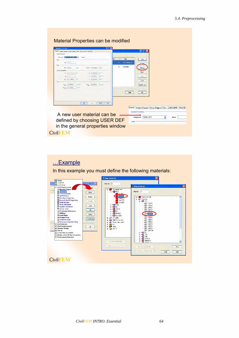
Material Properties can be modified
A new user material can bedefined by choosing USER DEFin the general properties window
In this example you must define the following materials:…Example
5.4. Preprocessing
CivilFEM INTRO. Essential 65
Element Type
• The element type is an important choice that determines the following element characteristics:
– Degree of Freedom (DOF) set. A thermal element type, for example, has one DOF: TEMP, whereas a structural element type may have up to six DOF: UX, UY, UZ, ROTX, ROTY, ROTZ.
– Element shape -- brick, tetrahedron, quadrilateral, triangle, etc.
– Dimensionality -- 2-D (X-Y plane only), or 3-D.
– Assumed displacement shape -- linear vs. quadratic.
– Non linear capabilities
• Details on how to choose the most suitable element type will be presented later. For now, let’s see how to define an element type.
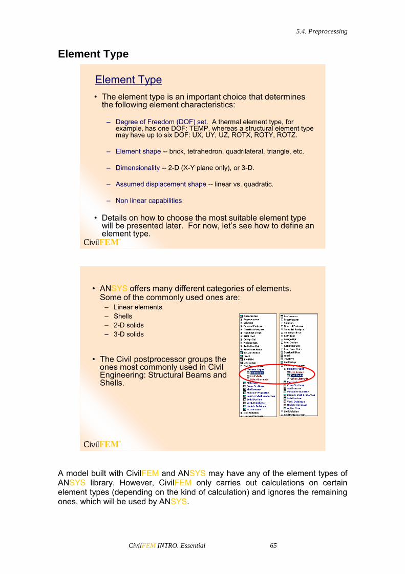
Element Type
• ANSYS offers many different categories of elements. Some of the commonly used ones are:
– Linear elements– Shells– 2-D solids– 3-D solids
• The Civil postprocessor groups the ones most commonly used in Civil Engineering: Structural Beams and Shells.
A model built with CivilFEM and ANSYS may have any of the element types of ANSYS library. However, CivilFEM only carries out calculations on certain element types (depending on the kind of calculation) and ignores the remaining ones, which will be used by ANSYS.

5.4. Preprocessing
CivilFEM INTRO. Essential 66
To continue the example, the next step is to select the elements to be used.
• From the complete element list:
…Example
In this example, the element PLANE42 has plane stress behavior. This behavior is the default for this element type and can be changed using the options window.

5.4. Preprocessing
CivilFEM INTRO. Essential 67
• From the structural Civil elements:
Element Attributes
• Calculations within ANSYS and CivilFEM require elements to have the following attributes:
– Element type: • Element type selected depending on the required dimensions
of the model, degrees of freedom, type of analysis: LINK1, BEAM3, BEAM4, SHELL, BEAM44, SHELL63...
– Set of real constants: • Data of the section properties, which depend on the element
type: Area, Inertia, depth...
• If you have selected link, beam, or shell elements with CivilFEM you must create the Beam and Shell Properties. Beam and Shell Properties include all the properties required for calculating and postprocessing with CivilFEM: properties of the cross sections (reinforcement data, plates structure,…), member properties, etc. CivilFEM automatically generates the set of real constants.
Element Attributes

5.4. Preprocessing
CivilFEM INTRO. Essential 68
– ANSYS Section: • Replaces the real constants (only valid in certain beams).• CivilFEM Beam and Shell Properties will also generate this
section automatically if needed.
– Material (CivilFEM or ANSYS generic material):• Material properties: elasticity modulus, density, Poisson’s
ratio, thermal expansion coefficient...
…ExampleDefine the cross section of the beam and the thickness of the shell.
Don’t forget to enter the number
of the material
Select IPE A 500 for beam section

5.4. Preprocessing
CivilFEM INTRO. Essential 69
Enter the thickness of the shell
Don’t forget to select the material
Next, define the Beam and Shell Properties (and the real constants) for the beam element.
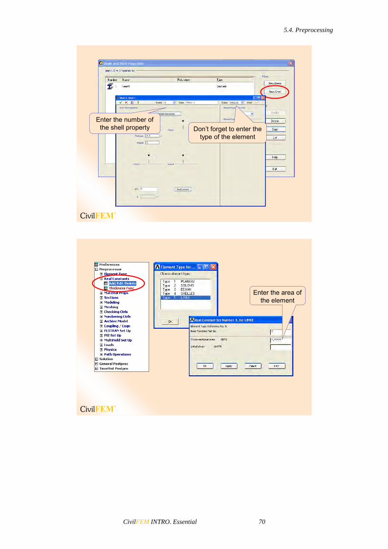
Don’t forget to enter the type of the element
Enter the number of the Beam property
The real constants group CivilFEM generates from the Beam and Shell Properties will have the same numbering as the beam and shell properties.
5.4. Preprocessing
CivilFEM INTRO. Essential 70
Don’t forget to enter the type of the element
Enter the number of the shell property
Enter the area of the element
5.4. Preprocessing
CivilFEM INTRO. Essential 71
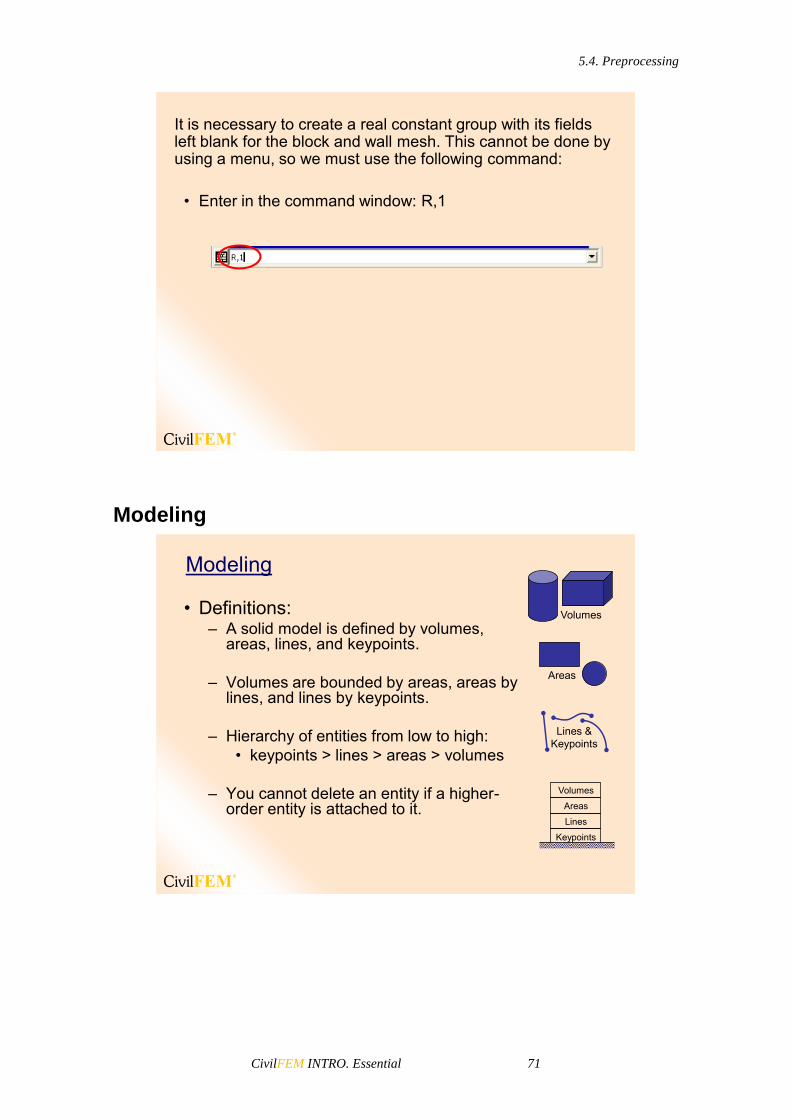
It is necessary to create a real constant group with its fields left blank for the block and wall mesh. This cannot be done by using a menu, so we must use the following command:
• Enter in the command window: R,1
Modeling
• Definitions:– A solid model is defined by volumes,
areas, lines, and keypoints.
– Volumes are bounded by areas, areas by lines, and lines by keypoints.
– Hierarchy of entities from low to high: • keypoints > lines > areas > volumes
– You cannot delete an entity if a higher-order entity is attached to it.
Volumes
Areas
Lines &Keypoints
Keypoints
Lines
Areas
Volumes
Modeling

5.4. Preprocessing
CivilFEM INTRO. Essential 72
• A model with areas and lower-order entities, such as a shell or 2-D plane model, is still considered a solid model in CivilFEM terminology.
• There are two approaches to creating a solid model:– Top-down– Bottom-up
Top-Down Modeling
• Top-down modeling starts with a definition of volumes (or areas) which are then combined in some fashion to create the final shape.
– Initially defined volumes or areas are called primitives.– Primitives are located and oriented with the help of the
working plane.– Combinations used to produce the final shape are
called Boolean operations.
add
5.4. Preprocessing
CivilFEM INTRO. Essential 73
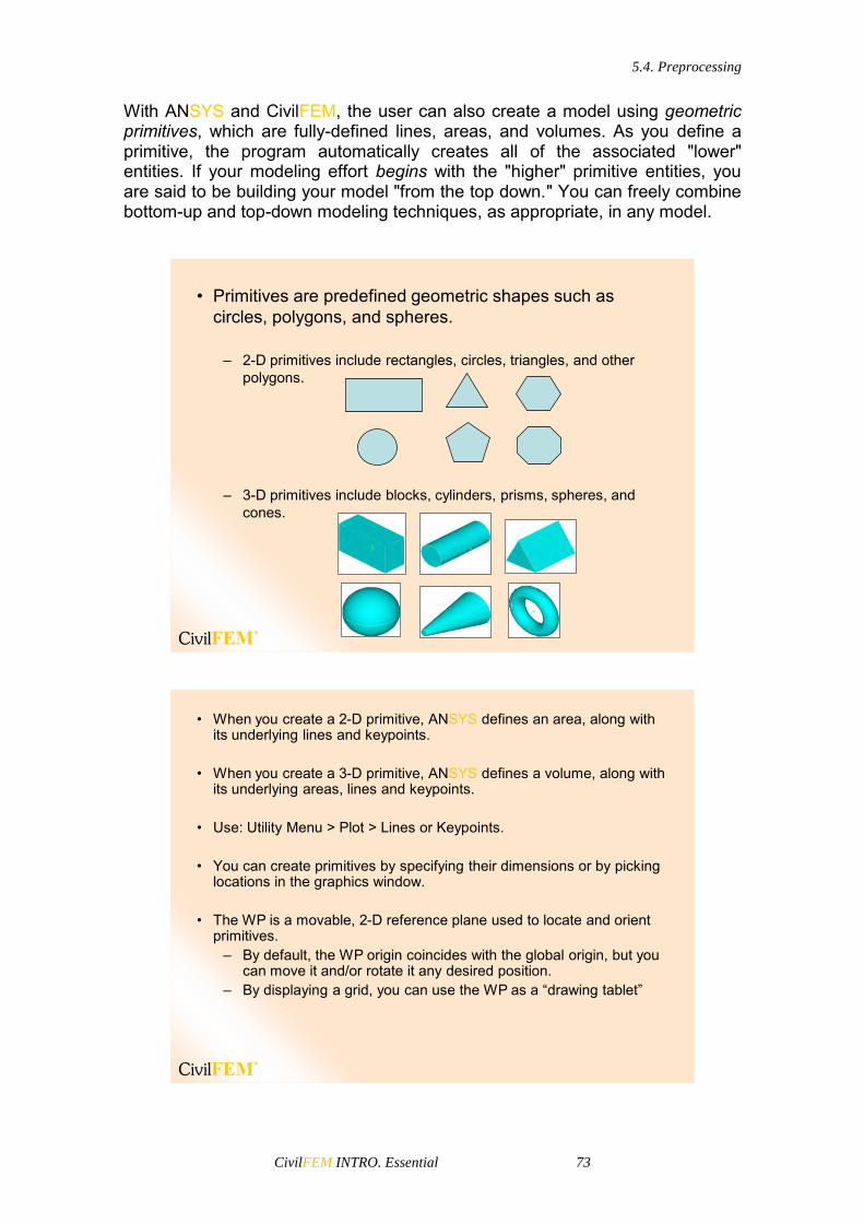
With ANSYS and CivilFEM, the user can also create a model using geometric primitives, which are fully-defined lines, areas, and volumes. As you define a primitive, the program automatically creates all of the associated "lower" entities. If your modeling effort begins with the "higher" primitive entities, you are said to be building your model "from the top down." You can freely combine bottom-up and top-down modeling techniques, as appropriate, in any model.
– 2-D primitives include rectangles, circles, triangles, and other polygons.
– 3-D primitives include blocks, cylinders, prisms, spheres, and cones.
• Primitives are predefined geometric shapes such as circles, polygons, and spheres.
• When you create a 2-D primitive, ANSYS defines an area, along with its underlying lines and keypoints.
• When you create a 3-D primitive, ANSYS defines a volume, along with its underlying areas, lines and keypoints.
• Use: Utility Menu > Plot > Lines or Keypoints.
• You can create primitives by specifying their dimensions or by picking locations in the graphics window.
• The WP is a movable, 2-D reference plane used to locate and orient primitives.
– By default, the WP origin coincides with the global origin, but you can move it and/or rotate it any desired position.
– By displaying a grid, you can use the WP as a “drawing tablet”

5.4. Preprocessing
CivilFEM INTRO. Essential 74
• All working plane controls are in Utility Menu > WorkPlane.
• The WP Settings menu controls are the following:
– WP display: triad only (default), grid only, or both.
– Snap: allows you to pick locations on the WP easily by “snapping” the cursor to the nearest grid point.
– Grid spacing: the distance between grid lines.
– Grid size: how much of the (infinite) working plane is displayed.
• You can move the WP to any desired position using the Offset and Align menus
– Offset WP by increments…– Offset WP to >
This simply relocates the WP, maintaining its current orientation, to the desired destination, which can be: existing keypoint(s), existing node(s), coordinate location(s), global origin, or origin of the active coordinate system.
– Align WP with > This reorients the WP.

5.4. Preprocessing
CivilFEM INTRO. Essential 75
• Boolean operations are computations involving combinations of geometric entities. Boolean operations include add, subtract, intersect, divide, glue and overlap.
• All Boolean operations are available in the GUI under Main Menu> Preprocessor> Modeling> Operate>Booleans
• Add: Combine two or more entities into one.• Glue: Attaches two or more entities by creating a
common boundary between them (useful when you want to maintain the distinction between entities).
• Overlap: Same as glue, except the input entities overlap each other.
• Subtract: Removes the overlapping portion of one or more entities from a set of “base” entities (useful for creating holes or trimming off portions of an entity).
• Divide: Cuts an entity into two or more pieces that are still connected to each other by common boundaries. The cutting tool may be the working plane, an area, a line, or even a volume.
• Intersect: Keeps only the overlapping portion of two or more entities. If there are more than two input entities, there are two choices: commonintersection and pairwise intersection:
– Common intersection finds the common overlapping region among all input entities.
– Pairwise intersection finds the overlapping region for each pair of entities and may produce more than one output entity
• Partition: Cuts two or more intersecting entities into multiple pieces that are still connected to each other by common boundaries.
Note: When you operate with two (or more) areas, the program assigns anumber to the total area by default. This choice is not arbitrary; theprogram searches for the first free number.

5.4. Preprocessing
CivilFEM INTRO. Essential 76
Bolean Operation Before Boolean
Operation
Alter Boolean
Operation
ADD
GLUE
OVERLAP

5.4. Preprocessing
CivilFEM INTRO. Essential 77
SUBTRACT
DIVIDE
INTERSECT
CommonIntersection
CommonIntersection
PairwiseIntersection
PairwiseIntersection
PARTITION L1
L2
L1
L2
L3
L6
L7L4
L3
L6
L7L4
5.4. Preprocessing
CivilFEM INTRO. Essential 78
Bottom-Up Modeling
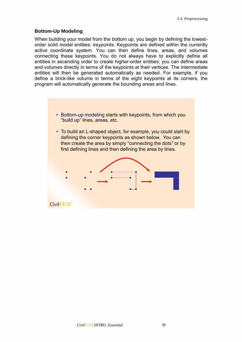
When building your model from the bottom up, you begin by defining the lowest-order solid model entities: keypoints. Keypoints are defined within the currently active coordinate system. You can then define lines, areas, and volumes connecting these keypoints. You do not always have to explicitly define all entities in ascending order to create higher-order entities; you can define areas and volumes directly in terms of the keypoints at their vertices. The intermediate entities will then be generated automatically as needed. For example, if you define a brick-like volume in terms of the eight keypoints at its corners, the program will automatically generate the bounding areas and lines.
• Bottom-up modeling starts with keypoints, from which you “build up” lines, areas, etc.
• To build an L-shaped object, for example, you could start by defining the corner keypoints as shown below. You can then create the area by simply “connecting the dots” or by first defining lines and then defining the area by lines.

5.4. Preprocessing
CivilFEM INTRO. Essential 79
Keypoints definition
• To define keypoints:– Main Menu > Preprocessor > Modeling > Create > Keypoints
• The only data needed to create a keypoint is the keypoint number and the coordinate location.
– Keypoint number defaults to the next available number.
– The coordinate location may be provided by simply picking locations on the working plane or by entering the X,Y,Z values.
1. KEYPOINTS
To define individual keypoints, use one of the methods listed in the following table:
In the active coordinate system
Main Menu> Preprocessor> Modeling> Create> Keypoints> In Active CS
Main Menu> Preprocessor> Modeling> Create> Keypoints> On Working Plane
At a given location on an existing line
Main Menu> Preprocessor> Modeling> Create> Keypoints> On Line
Main Menu> Preprocessor> Modeling> Create> Keypoints> On Line w/Ratio
Once you create an initial pattern of keypoints, you can generate additional keypoints and work with existing keypoints using several methods described in ANSYS Help: Modelling and Meshing Guide. Chapter 5.2: “Creating Your Solid Model from the Bottom Up”. Many Boolean operations will also create keypoints.
Hard Points Hard points are a special type of keypoints. You can use hard points to apply loads or to obtain data from arbitrary points on lines and areas within your model. Hard points do not modify either the geometry or the topology of your

5.4. Preprocessing
CivilFEM INTRO. Essential 80
model. Hard points have their own extension in the GUI under the keypoints extension. If you issue any commands that update the geometry of an entity, such as Boolean or simplification commands, any hard points associated with that entity will be deleted. Therefore, it is recommended to add hard points after completing the solid model. If you delete an entity that has associated hard points, the hard points are either:
Deleted along with the entity (if the hard points are not associated with any other entities).
Detached from the deleted entity (if the hard points are associated with additional entities).
You can define hard points on existing lines or areas. In both cases, you can define the location of hard points on such entities by:
Picking (unavailable for models imported from IGES files).
Specifying ratios (available for lines only).
Specifying global X, Y and Z coordinates. To create hard points, use one of the methods listed in the following table.
On an existing line
Main Menu> Preprocessor> Modeling> Create> Keypoints> Hard PT on line> Hard PT by ratio
Main Menu> Preprocessor> Modeling> Create> Keypoints> Hard PT on line> Hard PT by coordinates
Main Menu> Preprocessor> Modeling> Create> Keypoints> Hard PT on line> Hard PT by picking
On an existing area
Main Menu> Preprocessor> Modeling> Create> Keypoints> Hard PT on line> Hard PT by coordinates
Main Menu> Preprocessor> Modeling> Create> Keypoints> Hard PT on line> Hard PT by picking

5.4. Preprocessing
CivilFEM INTRO. Essential 81
…Example
To create the solid model, first define the keypoints. The number and the coordinates of the keypoints are the following.
KP number
Coordinates KP number
Coordinates KP number
Coordinates
1 15,0,15 6 15,15,0 11 0,30,0
2 15,0,0 7 0,15,0 12 0,30,15
3 0,0,0 8 0,15,15 13 30,15,15
4 0,0,15 9 15,30,15 14 30,15,0
5 15,15,15 10 15,30,0 15 30,30,0
KP 1
KP 2KP 3
KP 4
KP 5
KP 6KP 7
KP 8
KP 9
KP 10KP 11
KP 12
KP 13
KP 14
KP 15

5.4. Preprocessing
CivilFEM INTRO. Essential 82
To create the first KP:• Main Menu > Preprocessor > Modeling > Create >
Keypoints > In Active CSEnter the coordinates of KP number 1. Then, repeat with the other KPs. Enter the number and
the coordinates of the KP
Lines Definition Lines are mainly used to represent the edges of an object. As with keypoints, lines are defined within the currently active coordinate system. You do not always need to define all lines explicitly because the program will generate the necessary lines in many instances when an area or volume is defined. Lines are required if you want to generate line elements (such as beams) or to create areas from lines.
• There are many ways to create lines, as shown below.• If you define areas or volumes, ANSYS will automatically
generate any undefined lines with the curvature determined by the active CS.
• Keypoints must be defined in order to create lines.
Operate >Extrude
Create > Lines > Lines
Create > Lines > Arcs
Create > Lines > Splines
2. LINES
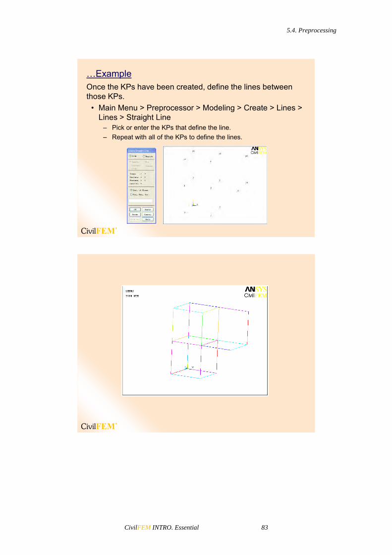
5.4. Preprocessing
CivilFEM INTRO. Essential 83
…ExampleOnce the KPs have been created, define the lines between those KPs.
• Main Menu > Preprocessor > Modeling > Create > Lines > Lines > Straight Line
– Pick or enter the KPs that define the line.– Repeat with all of the KPs to define the lines.

5.4. Preprocessing
CivilFEM INTRO. Essential 84
Areas Definition
• Creating areas using the bottom-up method requires the definition of keypoints or lines.
• If you define volumes, ANSYS will automatically generate any undefined areas and lines with the curvature determined by the active Coordinate System.
3. AREAS
Create > Areas > Arbitrary Operate > Extrude
Volume Definition
• Creating volumes using the bottom-up method require keypoints or areas to be already defined.
4. VOLUMES
Create > Volumes > Arbitrary Operate > Extrude

5.4. Preprocessing
CivilFEM INTRO. Essential 85
…ExampleFinally, we create areas and volumes to completely define the geometry of the model.
• Main Menu > Preprocessor > Modeling > Create > Volumes > Arbitrary > Through KPs
– Enter the KPs numbers to define the first volume.– Do the same with the KPs to define the second volume.
• Main Menu > Preprocessor > Modeling > Create > Areas > Arbitrary > Through KPs
– Enter the KPs numbers to define the first area: 5, 13, 14, 6.– Repeat with the remaining KPs to define the second area. The
second area is defined by the KPs 6, 14, 15, 10.

5.4. Preprocessing
CivilFEM INTRO. Essential 86
• Once all the areas and volumes have been created, the geometry is the following:
Another Useful Operation: Extrusion This option is used to quickly create volumes from existing areas (or areas from lines and lines from keypoints). If the area that is being extruded is meshed (or belongs to a meshed volume), the mesh will be used as a pattern for the mesh of the volume that is created.

5.4. Preprocessing
CivilFEM INTRO. Essential 87
There are four ways to extrude areas:
Along Normal: Creates a volume by normal offsets of areas.
By XYZ offset: Creates a volume by a general x-y-z offset.
About Axis: Creates a volume by revolving areas about an axis.
Along Lines: Creates a volume by “dragging” areas along a line or a set of adjoined lines.
Follow these steps to extrude your mesh: 1. Mesh the area that is to be extruded (using MESH200 elements).
2. Select an appropriate 3-D element type (match the shape and number of nodes to the MESH200 element), and change the element attributes.

5.4. Preprocessing
CivilFEM INTRO. Essential 88
3. Specify the desired number of element divisions in the extruded direction (NDIV argument). If using Extrude Along Lines, specify the number of element divisions on the drag path line(s) (NDIV argument).
4. Issue one of the following options (in this case Extrude by XYZ Offset):

5.4. Preprocessing
CivilFEM INTRO. Essential 89
Save Database and Resume
• It is good practice to save the database frequently because CivilFEM does NOT run automatic backups.
• The SAVE operation copies the database from memory to the files called database files.
– The easiest way to do a save is to click on Toolbar > SAVE– Or use ~CFSAVE command
• To restore the database from the db file back into memory, use the RESUME operation.
– Toolbar > RESUME– Or use ~CFRESUM command
Save Database and Resume

5.4. Preprocessing
CivilFEM INTRO. Essential 90
• The default file name for save (~CFSAVE) and resume (~CFRESUM) is jobname.cfdb, but you can choose a different name by using the “Change Jobname” (Utility menu> File> Change Jobname).
• The db file is simply a “snapshot” of what is in memory at the time the file is saved.
• CivilFEM database (.CFDB) and ANSYS database (.DB) files are created simultaneously.
• It is recomended to use ~CFRESUM and ~CFSAVE commands to resume and save ANSYS and CivilFEMdatabases simultaneously.
• When you save the database, CivilFEM also creates two more files: .DBB and .CFDBB. These files are the previous .DB and .CFDB backup files.
SAVE and RESUME commands will only operate on the ANSYS .DB database. It is therefore recommended to use the ~CFSAVE and ~CFRESUM commands, which operate on both databases.
…Example

5.4. Preprocessing
CivilFEM INTRO. Essential 91
Create Finite Element Model
• Meshing is the process used to “fill” the solid model with nodes and elements to create the FEA model.
• There are three steps needed for meshing:– Define element attributes – Specify mesh controls– Generate the mesh
Create Finite Element Model
Element Attributes definition
Before the mesh is created, the materials used must be defined, the element types selected from the library, and their properties identified (stress state, non-linear behaviour, etc.). If needed, the Beam & Shell Properties (or real constants groups for some solid elements) must be defined as well.
Each part of the model will need a different material or element type. Therefore, it is important to determine which attributes must to be assigned to the corresponding elements.
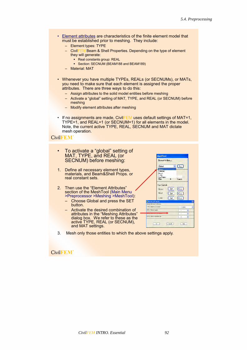
5.4. Preprocessing
CivilFEM INTRO. Essential 92
• Element attributes are characteristics of the finite element model that must be established prior to meshing. They include:
– Element types: TYPE– CivilFEM Beam & Shell Properties. Depending on the type of element
they will generate: Real constants group: REAL Section: SECNUM (BEAM188 and BEAM189)
– Material: MAT
• Whenever you have multiple TYPEs, REALs (or SECNUMs), or MATs, you need to make sure that each element is assigned the proper attributes. There are three ways to do this:
– Assign attributes to the solid model entities before meshing– Activate a “global” setting of MAT, TYPE, and REAL (or SECNUM) before
meshing– Modify element attributes after meshing
• If no assignments are made, CivilFEM uses default settings of MAT=1, TYPE=1, and REAL=1 (or SECNUM=1) for all elements in the model. Note, the current active TYPE, REAL, SECNUM and MAT dictate mesh operation.
• To activate a “global” setting of MAT, TYPE, and REAL (or SECNUM) before meshing:
1. Define all necessary element types, materials, and Beam&Shell Props. or real constant sets.
2. Then use the “Element Attributes” section of the MeshTool (Main Menu >Preprocessor >Meshing >MeshTool):– Choose Global and press the SET
button.– Activate the desired combination of
attributes in the “Meshing Attributes” dialog box. We refer to these as the active TYPE, REAL (or SECNUM), and MAT settings.
3. Mesh only those entities to which the above settings apply.
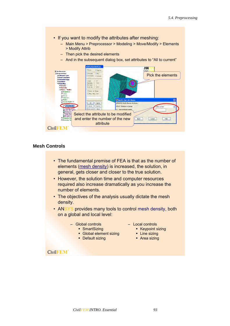
5.4. Preprocessing
CivilFEM INTRO. Essential 93
• If you want to modify the attributes after meshing:– Main Menu > Preprocessor > Modeling > Move/Modify > Elements
> Modify Attrib– Then pick the desired elements– And in the subsequent dialog box, set attributes to “All to current”
Select the attribute to be modified and enter the number of the new
attribute
Pick the elements
Mesh Controls
• The fundamental premise of FEA is that as the number of elements (mesh density) is increased, the solution, in general, gets closer and closer to the true solution.
• However, the solution time and computer resources required also increase dramatically as you increase the number of elements.
• The objectives of the analysis usually dictate the mesh density.
• ANSYS provides many tools to control mesh density, both on a global and local level:
– Global controls SmartSizing Global element sizing Default sizing
– Local controls Keypoint sizing Line sizing Area sizing
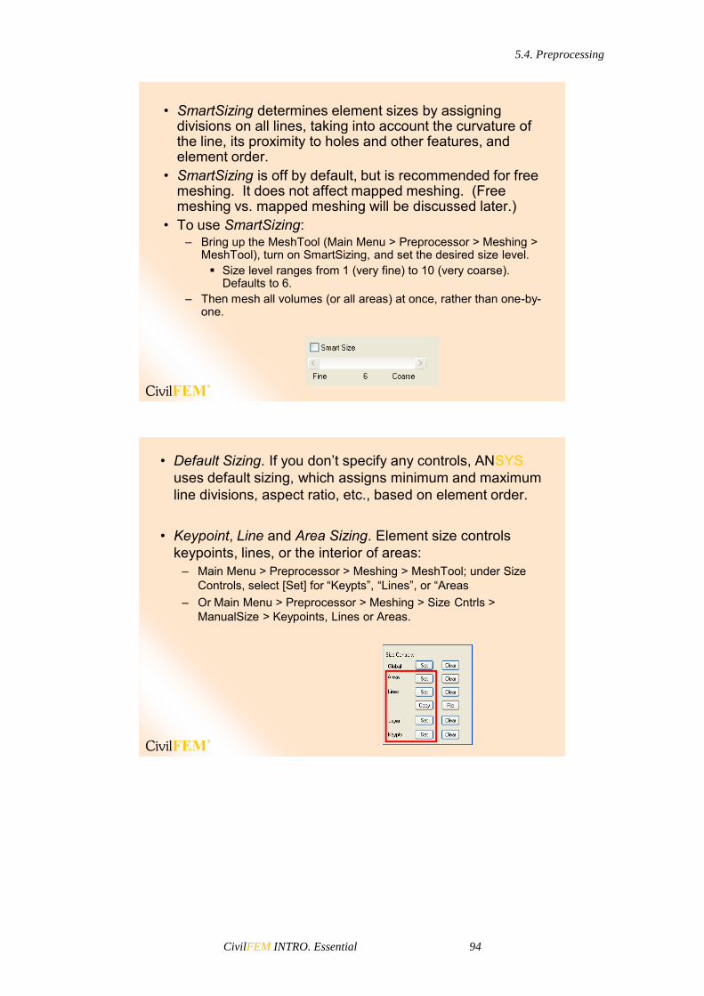
5.4. Preprocessing
CivilFEM INTRO. Essential 94
• SmartSizing determines element sizes by assigning divisions on all lines, taking into account the curvature of the line, its proximity to holes and other features, and element order.
• SmartSizing is off by default, but is recommended for free meshing. It does not affect mapped meshing. (Free meshing vs. mapped meshing will be discussed later.)
• To use SmartSizing:– Bring up the MeshTool (Main Menu > Preprocessor > Meshing >
MeshTool), turn on SmartSizing, and set the desired size level. Size level ranges from 1 (very fine) to 10 (very coarse).
Defaults to 6.– Then mesh all volumes (or all areas) at once, rather than one-by-
one.
• Default Sizing. If you don’t specify any controls, ANSYS uses default sizing, which assigns minimum and maximum line divisions, aspect ratio, etc., based on element order.
• Keypoint, Line and Area Sizing. Element size controls keypoints, lines, or the interior of areas:
– Main Menu > Preprocessor > Meshing > MeshTool; under Size Controls, select [Set] for “Keypts”, “Lines”, or “Areas
– Or Main Menu > Preprocessor > Meshing > Size Cntrls > ManualSize > Keypoints, Lines or Areas.

5.4. Preprocessing
CivilFEM INTRO. Essential 95
• Default Sizing. If you don’t specify any controls, ANSYS uses default sizing, which assigns minimum and maximum line divisions, aspect ratio, etc., based on element order.
• Keypoint, Line and Area Sizing. Element size controls keypoints, lines, or the interior of areas:
– Main Menu > Preprocessor > Meshing > MeshTool; under Size Controls, select [Set] for “Keypts”, “Lines”, or “Areas
– Or Main Menu > Preprocessor > Meshing > Size Cntrls > ManualSize > Keypoints, Lines or Areas.
Mesh generation
• Generating The Mesh is the final step in meshing.
– First save the database.– Then press [Mesh] in the MeshTool.
This brings up a picker. Press [Pick All] in the picker to indicate all entities.
– If a mesh is not acceptable, you can always re-mesh the model by following these steps:
1. Clear the mesh: The clear operation is the opposite
of mesh: it removes nodes and elements.
Use the [Clear] button on the MeshTool.
2. Specify new or different mesh controls.3. Mesh again.
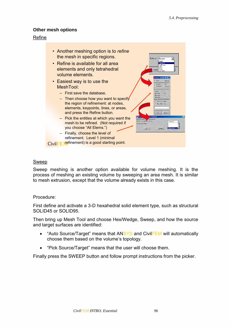
5.4. Preprocessing
CivilFEM INTRO. Essential 96
Other mesh options
Refine
• Another meshing option is to refinethe mesh in specific regions.
• Refine is available for all area elements and only tetrahedral volume elements.
• Easiest way is to use the MeshTool:
– First save the database.– Then choose how you want to specify
the region of refinement: at nodes, elements, keypoints, lines, or areas, and press the Refine button.
– Pick the entities at which you want the mesh to be refined. (Not required if you choose “All Elems.”)
– Finally, choose the level of refinement. Level 1 (minimal refinement) is a good starting point.
Sweep Sweep meshing is another option available for volume meshing. It is the process of meshing an existing volume by sweeping an area mesh. It is similar to mesh extrusion, except that the volume already exists in this case.
Procedure:
First define and activate a 3-D hexahedral solid element type, such as structural SOLID45 or SOLID95.
Then bring up Mesh Tool and choose Hex/Wedge, Sweep, and how the source and target surfaces are identified:
“Auto Source/Target” means that ANSYS and CivilFEM will automatically choose them based on the volume’s topology.
“Pick Source/Target” means that the user will choose them.
Finally press the SWEEP button and follow prompt instructions from the picker.

5.4. Preprocessing
CivilFEM INTRO. Essential 97
Volume sweeping is useful if:
You have imported a solid model that was created in another program, and you want to mesh it in ANSYS and CivilFEM.
You want to create a hexahedral mesh for an irregular volume. In this case, you only have to break up the volume into a series of discrete sweepable regions.
You either want to create a different mesh than the one that was created by one of the other extrusion methods or you forgot to create a mesh during one of those operations.
If you do not mesh the source area prior to volume sweeping; ANSYS meshes it for you when you invoke the volume sweeper. The other extrusion methods require you to mesh the area yourself before you invoke them. If you do not, the other extrusion methods create the volume, but no area or volume mesh is generated.

5.4. Preprocessing
CivilFEM INTRO. Essential 98
Meshing Methods
• There are two main meshing methods: free and mapped.
• Free Mesh– Has no element shape restrictions.– The mesh does not follow any pattern.– Suitable for complex shaped areas and
volumes.
• Mapped Mesh– Restricts element shapes to
quadrilaterals for areas and hexahedral (bricks) for volumes.
– Typically has a regular pattern with obvious rows of elements.
– Suitable only for “regular” areas and volumes such as rectangles and bricks.
Free Mesh
• Creating a free mesh is simple:– Bring up the MeshTool and verify that free meshing
is set.– SmartSizing is generally recommended for free
meshing, so activate it and specify a size level. Save the database.
– Then initiate the mesh by pressing the Mesh button. Press [Pick All] in the picker to choose all
entities (recommended).
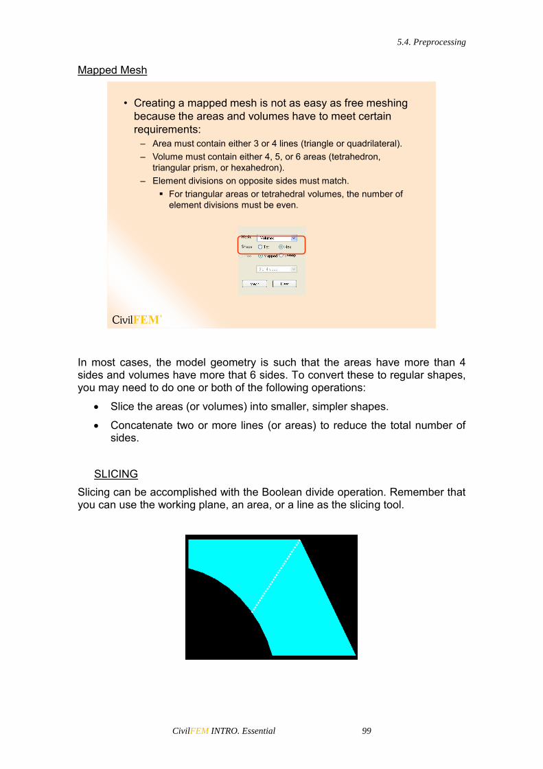
5.4. Preprocessing
CivilFEM INTRO. Essential 99
Mapped Mesh
• Creating a mapped mesh is not as easy as free meshing because the areas and volumes have to meet certain requirements:
– Area must contain either 3 or 4 lines (triangle or quadrilateral).– Volume must contain either 4, 5, or 6 areas (tetrahedron,
triangular prism, or hexahedron).– Element divisions on opposite sides must match.
For triangular areas or tetrahedral volumes, the number of element divisions must be even.
In most cases, the model geometry is such that the areas have more than 4 sides and volumes have more that 6 sides. To convert these to regular shapes, you may need to do one or both of the following operations:
Slice the areas (or volumes) into smaller, simpler shapes.
Concatenate two or more lines (or areas) to reduce the total number of sides.
SLICING
Slicing can be accomplished with the Boolean divide operation. Remember that you can use the working plane, an area, or a line as the slicing tool.
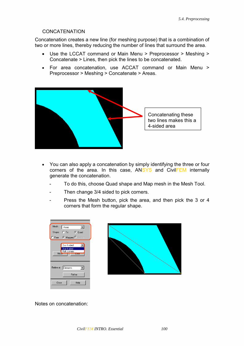
5.4. Preprocessing
CivilFEM INTRO. Essential 100
CONCATENATION Concatenation creates a new line (for meshing purpose) that is a combination of two or more lines, thereby reducing the number of lines that surround the area.
Use the LCCAT command or Main Menu > Preprocessor > Meshing > Concatenate > Lines, then pick the lines to be concatenated.
For area concatenation, use ACCAT command or Main Menu > Preprocessor > Meshing > Concatenate > Areas.
You can also apply a concatenation by simply identifying the three or four corners of the area. In this case, ANSYS and CivilFEM internally generate the concatenation. - To do this, choose Quad shape and Map mesh in the Mesh Tool. - Then change 3/4 sided to pick corners. - Press the Mesh button, pick the area, and then pick the 3 or 4
corners that form the regular shape.
Notes on concatenation:
Concatenating these two lines makes this a 4-sided area

5.4. Preprocessing
CivilFEM INTRO. Essential 101
If concatenations are present ANSYS and CivilFEM will not allow the extrusion operation.
It is purely a meshing operation and therefore should be the last step before meshing, after all solid modelling operations. This is because the output entity obtained from a concatenation cannot be used in any subsequent solid modelling operation.
You can “undo” a concatenation by deleting the line or area it produced.
Concatenating areas (for mapped volume meshing) is generally much more complicated because you may also need to concatenate some lines. Lines are automatically concatenated only when two adjacent, 4-sided areas are concatenated.
…ExampleOnce the geometry is totally defined, we generate the mesh. Element types and materials are the following:
• Main Menu >Preprocessor >Meshing >MeshTool
Mat: ConcreteET: Solid45 Mat: Concrete
ET: Plane42
Mat: ConcreteET: Shell63
Mat: SteelET: Beam4
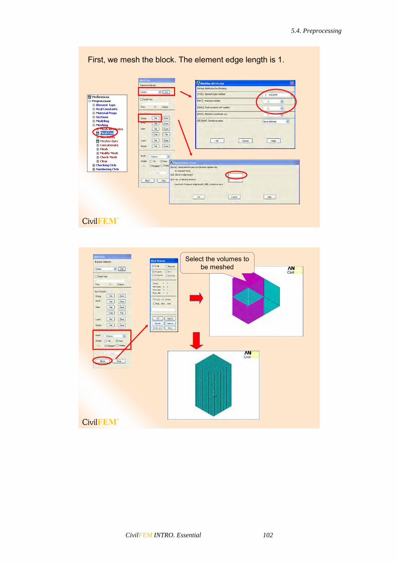
5.4. Preprocessing
CivilFEM INTRO. Essential 102
First, we mesh the block. The element edge length is 1.
Select the volumes to be meshed

5.4. Preprocessing
CivilFEM INTRO. Essential 103
Now we mesh the two areas. The element edge length is the same.
Select the area to be meshed
Select the area to be meshed

5.4. Preprocessing
CivilFEM INTRO. Essential 104
Finally we mesh the beams.
Select the lines to be meshed
Select the lines to be meshed
Selection and Components
If you have a large model, it is helpful to work with just a portion of the model data to apply loads, to speed up graphics displays, to review results selectively, and so on. Because all ANSYS and CivilFEM data are in a database, you can conveniently choose subsets of the data by selecting them. Selection Tools
Selecting enables you to group subsets of nodes, elements, keypoints, lines, etc. so that you can work with just a handful of entities. The ANSYS and CivilFEM program uses a database to store all the data that you define during an analysis. The database design allows you to select only a portion of the data without destroying other data.

5.4. Preprocessing
CivilFEM INTRO. Essential 105
• The selection Tools allows you to select a subset of entities and operate only on those entities.
• Most selecting tools are available in the Select Entities dialog box: Utility Menu > Select > Entities…
Entity to select
Criterion bywhich to select
Type ofselection
Selection Tools
The GUI path is Utility Menu> Select> Entities. From the Select Entities dialog box the user can choose, among other things, the type of entities and the criteria by which the entities are selected:
• Criterion by which to select:
– By Num/Pick: based on entity numbers or by picking.
– Attached to: based on attached entities. For example, select all lines attached to the current subset of areas.
– By Location: based on X,Y,Z location. For example, select all nodes at X=2.5. X,Y,Z are interpreted in the active coordinate system.
– By Attributes: based on material number, real constant set number, etc. Different attributes are available for different entity types.
– Exterior: used to select entities lying on the exterior.
– By Results: used to select entities by results data. For example, nodal displacements.

5.4. Preprocessing
CivilFEM INTRO. Essential 106
• Type of selection– From Full: selects a subset
from the full set of entities.– Reselect: selects (again) a
subset from the current subset.
– Also Select: adds another subset to the current subset.
– Unselect: deactivates a portion of the current subset.
– Invert: toggles the active and inactive subsets.
– Select None: deactivates the full set of entities.
– Select All: reactivates the full set of entities.
Select None
Reselect
Also Select
Unselect
Invert
From Full
Select All
• After all desired operations are completed on the selected subset, it is recommended to reactivate the full set of entities.
– If all nodes and all elements are not active for a solution, the solver will issue a warning to that effect.
• The simplest way to reactivate the full set is to select “everything”:
– Utility Menu > Select > Everything
• You can also use the [Sele All] button in the Select Entities dialog box to reactivate each entity set separately.
Selecting can also help the user during postprocessing. For instance, in POST1, you can select just a portion of your model to display or list the results. You should always use selecting to obtain meaningful results in POST1 when the model has discontinuities. Sometimes it is convenient to group portions of the model and give them recognizable names. These groupings may be components or assemblies.

5.4. Preprocessing
CivilFEM INTRO. Essential 107
Components
A component consists of one type of entity: nodes, elements, keypoints, lines, areas or volumes.
• Another available operation is to assign a name to the selected subset by creating a component. The name can be used in dialog boxes or commands in place of entity numbers or the label ALL.
• A group of nodes, elements, keypoints, lines, areas, or volumes can be defined as a component. Only one entity type is associated with a component.
• Components can be selected or unselected. When you select a component, you are actually selecting all of the entities in that component.
Assemblies
An assembly may consist of any number of components and other assemblies (both of which must have been previously defined). Use the CMGRP command (Utility Menu> Select> Comp/Assembly> Create Assembly) to define an assembly.

5.4. Preprocessing
CivilFEM INTRO. Essential 108
• Component Manager is used to Create, Display, List and Select Components and Assemblies.
– Utility Menu > Select > Component Manager…
Enter the name
All of the currentlyselected entities
will be included inthe component, or
you can select(pick) the desired
entities at this step.
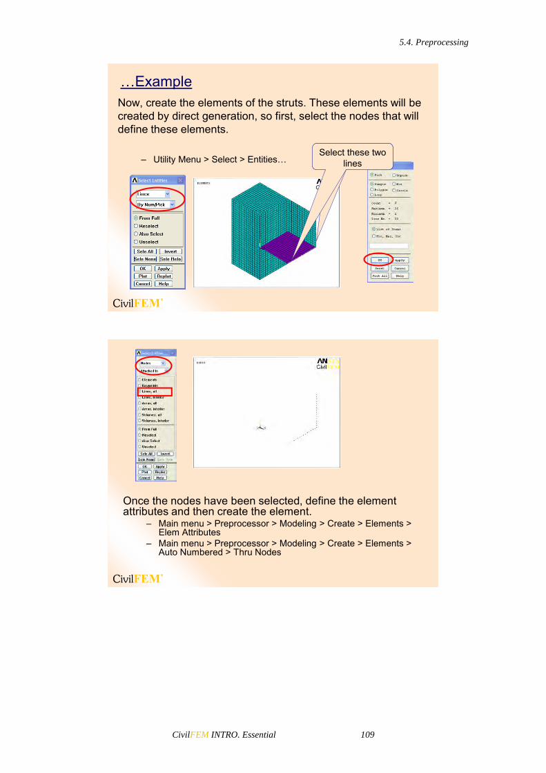
5.4. Preprocessing
CivilFEM INTRO. Essential 109
Now, create the elements of the struts. These elements will be created by direct generation, so first, select the nodes that will define these elements.
– Utility Menu > Select > Entities…
…Example
Select these two lines
Once the nodes have been selected, define the element attributes and then create the element.
– Main menu > Preprocessor > Modeling > Create > Elements > Elem Attributes
– Main menu > Preprocessor > Modeling > Create > Elements > Auto Numbered > Thru Nodes

5.4. Preprocessing
CivilFEM INTRO. Essential 110
Select these nodes
– Utility Menu > Select > Everything…
And now the other strut.
Select these two lines

5.4. Preprocessing
CivilFEM INTRO. Essential 111
Select these nodes
If you select everything and plot the elements, you can see the complete finite element model.
– Utility Menu > Select > Everything…– Utility Menu > Plot > Elements

5.5. Solution
CivilFEM INTRO. Essential 112
5.5 Solution
The word “loads” in ANSYS and CivilFEM terminology includes boundary conditions and externally or internally applied forcing functions.
5.5 SOLUTION
• The solution step is where we apply loads and boundary conditions on the object and let the solver calculate the finite element solution.
• Loads are available both in the Solution and Preprocessor menus.
Loads and Boundary Conditions

5.5. Solution
CivilFEM INTRO. Essential 113
Types of loads
• There are five categories of loads:
DOF Constraints Specified DOF values, such as displacements in a stress analysis or temperatures in a thermal analysis.
Concentrated Loads Point loads, such as forces or heat flow rates.
Surface Loads Loads distributed over a surface, such as pressures or convections.
Body Loads Volumetric or field loads, such as temperatures (causing thermal expansion).
Inertia Loads Loads due to structural mass or inertia, such as gravity and rotational velocity.
You can apply most loads either on the solid model (on keypoints, lines, and areas) or on the finite element model (on nodes and elements). For example, you can specify forces at a keypoint or at a node. Similarly, you can specify convections (and other surface loads) on lines and areas or on nodes and element faces. No matter how you specify the loads, the solver expects all loads to be in terms of the finite element model. Therefore, if you specify loads on the solid model, the program automatically transfers them to the nodes and elements at the beginning of solution.
Solid-Model Loads
Advantages:
Solid-model loads are independent of the finite element mesh. Therefore, the element mesh can be changed without affecting the applied loads. This allows you to make mesh modifications and conduct mesh sensitivity studies without having to reapply loads each time.
The solid model usually involves fewer entities than the finite element model. Therefore, selecting solid model entities and applying loads on them is much easier, especially with graphical picking.
Disadvantages:
Elements generated by ANSYS and CiviFEM meshing commands are in the currently active element coordinate system. Nodes generated by meshing commands use the global Cartesian coordinate system (by
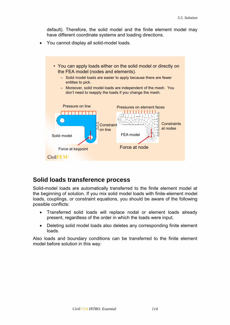
5.5. Solution
CivilFEM INTRO. Essential 114
default). Therefore, the solid model and the finite element model may have different coordinate systems and loading directions.
You cannot display all solid-model loads.
• You can apply loads either on the solid model or directly on the FEA model (nodes and elements).
– Solid model loads are easier to apply because there are fewer entities to pick.
– Moreover, solid model loads are independent of the mesh. You don’t need to reapply the loads if you change the mesh.
Constraints at nodes
FEA model
Pressures on element faces
Force at node
Constraint on line
Solid model
Pressure on line
Force at keypoint
Solid loads transference process
Solid-model loads are automatically transferred to the finite element model at the beginning of solution. If you mix solid model loads with finite-element model loads, couplings, or constraint equations, you should be aware of the following possible conflicts:
Transferred solid loads will replace nodal or element loads already present, regardless of the order in which the loads were input.
Deleting solid model loads also deletes any corresponding finite element loads.
Also loads and boundary conditions can be transferred to the finite element model before solution in this way:

5.5. Solution
CivilFEM INTRO. Essential 115
Plot and List Loads
Verifying applied loads
• Plot the applied loads by activating load symbols:
– Utility Menu > PlotCtrls > Symbols
• Or list them:– Utility Menu > List > Loads

5.5. Solution
CivilFEM INTRO. Essential 116
… ExampleTo apply the boundary conditions on the bottom surface of the block, select the nodes of that surface.
– Utility Menu > Select > Entities…– Main Menu > Solution > Define Loads > Apply >
Structural > Displacement > on Nodes
Enter the coordinates to the plane of nodes to be
selected
Select UX, UY and UZ directions
– Utility Menu > Select > Everything– Plot > Elements

5.5. Solution
CivilFEM INTRO. Essential 117
You can apply a linearly varying surface load, such as hydrostatic pressure on a structure immersed in water: - GUI:
Main Menu> Preprocessor> Loads> Define Loads> Settings> For Surface Ld> Gradient
Main Menu> Solution> Define Loads> Settings> For Surface Ld> Gradient
- Command: SFGRAD To create the gradient specification, you specify the type of load to be controlled (the Lab argument), the coordinate system and coordinate direction the slope is defined in (SLKCN and Sldir, respectively), the coordinate location where the value of the load (as specified on a subsequent surface load command) will be in effect (SLZER), and the slope (SLOPE).
Now, apply all the loads.• Hydrostatic PressureFirst we have to select the elements where the pressure willbe applied
– Utility Menu > Select > Entities

5.5. Solution
CivilFEM INTRO. Essential 118
Then, we define the pressure gradient to be applied– Main Menu > Solution > Define Loads > Settings > For Surface Ld
> Gradient
And finally we apply the pressure on the selected elements– Main Menu > Solution > Define Loads > Apply > Structural >
Pressure > On Elements
Enter the element face where the
pressure is applied.
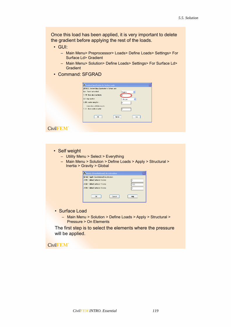
5.5. Solution
CivilFEM INTRO. Essential 119
Once this load has been applied, it is very important to delete the gradient before applying the rest of the loads.
• GUI:– Main Menu> Preprocessor> Loads> Define Loads> Settings> For
Surface Ld> Gradient – Main Menu> Solution> Define Loads> Settings> For Surface Ld>
Gradient
• Command: SFGRAD
• Self weight– Utility Menu > Select > Everything– Main Menu > Solution > Define Loads > Apply > Structural >
Inertia > Gravity > Global
• Surface Load– Main Menu > Solution > Define Loads > Apply > Structural >
Pressure > On Elements
The first step is to select the elements where the pressure will be applied.

5.5. Solution
CivilFEM INTRO. Essential 120
To select these elements, select the top area of the block, then the nodes located in this area, and the finally the elements that are attached to those nodes.
– Utility Menu > Select > Entities
Now apply the pressure:– Main Menu > Solution > Define Loads > Apply > Structural >
Pressure > On ElementsEnter the number of the face where the load is
going to be applied
Enter the value of the pressure
Pressures are applied perpendicular to the element surfaces. Faces where the pressure will be applied are represented by number; this numbering depends on the element type. Information about face numbers can be found in element type help. In this example, the element type used for the terrain is SOLID45. This is a 3D solid element defined by eight nodes and six faces. The geometry, node
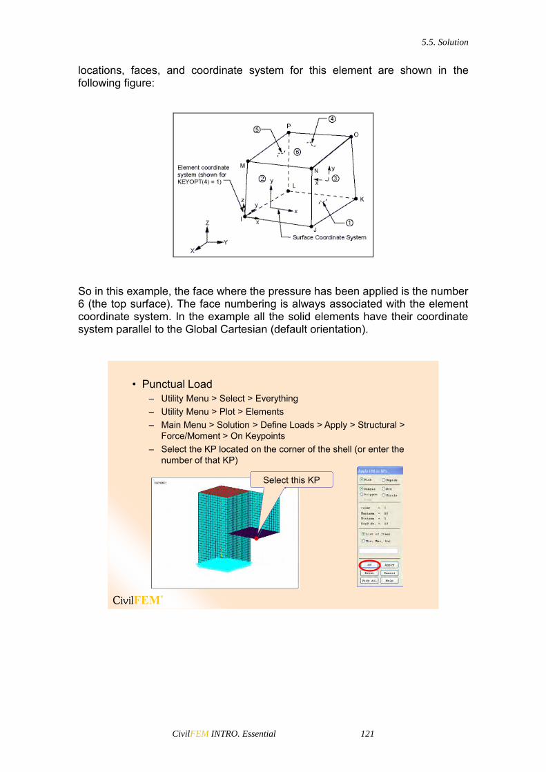
5.5. Solution
CivilFEM INTRO. Essential 121
locations, faces, and coordinate system for this element are shown in the following figure:
So in this example, the face where the pressure has been applied is the number 6 (the top surface). The face numbering is always associated with the element coordinate system. In the example all the solid elements have their coordinate system parallel to the Global Cartesian (default orientation).
• Punctual Load– Utility Menu > Select > Everything– Utility Menu > Plot > Elements– Main Menu > Solution > Define Loads > Apply > Structural >
Force/Moment > On Keypoints– Select the KP located on the corner of the shell (or enter the
number of that KP)
Select this KP

5.5. Solution
CivilFEM INTRO. Essential 122
Then enter the direction and the value of the force. This load will be transferred to the nodes in the solution process.
• Thermal Increment– Utility Menu > Select > Everything– Utility Menu > Plot > Elements– Main Menu > Solution > Define Loads > Apply > Structural >
Temperature > On Areas– Select the area of the wall
Select this area

5.5. Solution
CivilFEM INTRO. Essential 123
You can verify this load:– Utility menu > List > Loads > Body > On All Areas
Enter the temperature
Solve The Model
Once the loads and boundary conditions have been applied, the next step is to solve the model. This can be done through the menu:
– Main Menu > Solution > Solve > Current LS
Solve
Before you solve, you must select the type of analysis to be done.
– Main Menu > Solution > Analysis Type > New Analysis
These different options of analysis will be explained in the following days.

5.5. Solution
CivilFEM INTRO. Essential 124
… Example
• Select all the entities before solving the model.– Utility Menu > Select >Everything– Main Menu > Solution > Solve > Current LS
Results File
• When the model has been solved, the results file is created. CivilFEM results file (.RCV) is created simultaneously with ANSYS results file (.RST).
• A CivilFEM results file has a similar structure as an ANSYSresults file. Load step number 1 in the .RST file corresponds to the load step 1 in the .RCV, which contains additional data calculated by CivilFEM for postprocessing(such as stress and strain in each section point, forces and moments for solid sections…).
• .RCV file also contains the results of check and design processes. These results are stored in blocks called ALTERNATIVES.
• The additional data and results contained in the CivilFEMfiles are not considered for analysis in ANSYS.
Results file

5.5. Solution
CivilFEM INTRO. Essential 125
The name of the ANSYS results file depends on the analysis discipline:
Jobname.RST for a structural analysis. Jobname.RTH for a thermal analysis. Jobname.RMG for a magnetic field analysis.
CivilFEM will create a parallel results file:
Jobname.RCV for a structural analysis. CivilFEM will not add new results to thermal or magnetic analyses.
Therefore, to resume the results from a structural analysis, it is necessary to have the ANSYS RST file and the CivilFEM RCV file (RCV file does NOT substitute the RST file).
5.6. Postprocessing
CivilFEM INTRO. Essential 126
5.6 Postprocessing
Postprocessing refers to reviewing the results of an analysis. It is arguably the most important step in the analysis because the user can observe how the applied loads have affected the design or model, the quality finite element mesh, etc. Two postprocessors are available for reviewing the results: POST1, the general postprocessor and POST26, the time-history postprocessor.
POST1 allows you to review the results over the entire model at specific load steps and substeps (or at specific time-points or frequencies).
POST26 allows you to review the variation of a particular result item at specific points in the model with respect to time, frequency, or some other result item.
In this essential training manual the only postprocessor that will be explained is the general postprocessor (POST1). The time-history postprocessor, POST26, is explained in the advanced training manual. The solution phase calculates two types of results data:
Primary data consist of the degree-of-freedom solution calculated at each node: displacements in a structural analysis, temperatures in a thermal analysis, and magnetic potentials in a magnetic analysis. These are also known as nodal solution data.
Derived data are those results calculated from the primary data, such as stresses and strains in a structural analysis, thermal gradients and fluxes in a thermal analysis, magnetic fluxes in a magnetic analysis, etc. They are typically calculated for each element and may be reported at any of the following locations: all nodes of each element, all integration points of each element, or the centroid of each element. Derived data are also known as element solution data, except when they are averaged at the nodes. In such cases, they become nodal solution data.
To enter the ANSYS general postprocessor: Main Menu> General Postproc. To enter the CivilFEM Civil Engineering particular processor: Main Menu> Civil Postprocessor.

5.6. Postprocessing
CivilFEM INTRO. Essential 127
5.6 POSTPROCESSING
You can plot and list results such as reactions, stress, strain, etc. with ANSYS and forces and moments or results on cross sections with CivilFEMThe first step is to read the results for each load step.
Once the desired results data are loaded into the computer’s memory, you can review them through graphics displays and tabular listings. In addition, you can map the results data onto a path.
Graphics displays are perhaps the most effective way to review results.

5.6. Postprocessing
CivilFEM INTRO. Essential 128
Types of ANSYS Postprocessor Graphics
You can display the following types of graphics with ANSYSpostprocessor:
• Deformed Shape Displays• Contour Displays• Vector Displays• Path Plots
You can display the following types of graphics with ANSYSpostprocessor:
• Deformed Shape Displays• Contour Displays• Vector Displays• Path Plots

5.6. Postprocessing
CivilFEM INTRO. Essential 129
• Vector DisplaysVector displays use arrows to show the variation of both the magnitude and direction of a vector quantity in the model. Examples of vector quantities are displacement (U), rotation (ROT), magnetic vector potential (A), magnetic flux density (B), thermal flux (TF), thermal gradient (TG), fluid velocity (V), principal stresses (S), etc.To produce a vector display, use the following:
– Main Menu > General Postproc > Plot Results > Vector Plot
• Path PlotsThese are graphs that show the variationof a quantity along a predefined paththrough the model. To produce a pathplot, perform these tasks:
– Define a path. Main Menu > General Postproc > Path
Operations > Define Path > By Nodes, On Working Plane or By Location
– Map data onto the path. General Postproc > Path Operations >
Map onto Path

5.6. Postprocessing
CivilFEM INTRO. Essential 130
– Plot the Data. Main Menu > General Postproc > Path Operations > Plot Path
Item > On Graph. Main Menu > General Postproc > Path Operations > Plot Path
Item > On Geometry.
Note: Path operations are only applicable for nodes and elements results and therefore, not for cross section and shell vertex results.
CivilFEM Postprocessor
With the CivilFEM postprocessor you can display forces and moments graphics and section results. To display these graphs, use CivilFEM entities (Beam & Shell Properties must be defined).
– Main Menu > Civil Postprocessor > Beam Utilities > Graph Results– Main Menu > Civil Postprocessor > Shell Utilities > Graph Results
These graphics and section results are only available if the model contains CivilFEM entities. Beam and Shell Properties or Solid Sections, must be used.
With CivilFEM, axial and shear forces and torsion and bending moments can be displayed or listed.

5.6. Postprocessing
CivilFEM INTRO. Essential 131
• Forces and Moments in Beam Elements– Main Menu >Civil Postprocessor > Beam Utilities > Graph
Results > Forces & Moments
In beam elements, axial and shear forces and also bending moments can either be plotted or listed.
Graph results are plotted in a window similar to any other ANSYS result.
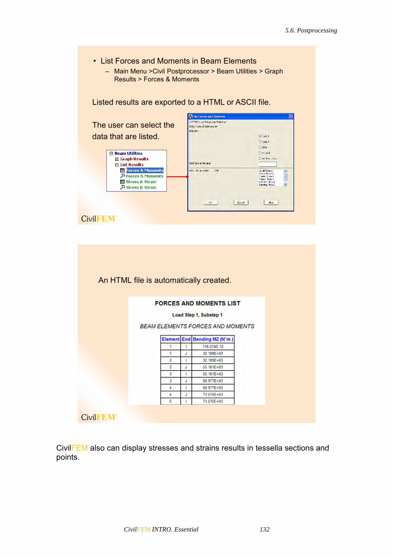
5.6. Postprocessing
CivilFEM INTRO. Essential 132
Listed results are exported to a HTML or ASCII file.
The user can select thedata that are listed.
• List Forces and Moments in Beam Elements– Main Menu >Civil Postprocessor > Beam Utilities > Graph
Results > Forces & Moments
An HTML file is automatically created.
CivilFEM also can display stresses and strains results in tessella sections and points.

5.6. Postprocessing
CivilFEM INTRO. Essential 133
In CivilFEM it is necessary to create and assign cross sections as well as real constants to beam elements in order to calculate elastic normal stresses in cross sections.The forces applied on these cross sections are also listed.
• Stresses and Forces in Cross Section– Main Menu >Civil Postprocessor > Beam Utilities > Graph
Results > Section Results
RESULTS DESCRIPTION
SX Represents stress in the X direction of the section.
SY Represents stress in the Y direction of the section.
SZ Represents stress in the Z direction of the section.
SXY Represents XY tangential stress of the section.
SYZ Represents YZ tangential stress of the section.
SZX Represents ZX tangential stress of the section.
EPX Represents elastic strain in the X direction of the section.
EPY Represents elastic strain in the Y direction of the section.
EPZ Represents elastic strain in the Z direction of the section.
EPXY Represents XY tangential elastic strain of the section.
EPYZ Represents YZ tangential elastic strain of the section.
EPZX Represents ZX tangential elastic strain of the section.

5.6. Postprocessing
CivilFEM INTRO. Essential 134
Forces are always listed. Stresses can be plotted in tessella or in points.
Section Data
Tessella results
Points results
Section Data

5.6. Postprocessing
CivilFEM INTRO. Essential 135
Following the same procedure as for beams, forces and moments can be plotted or listed for shell elements as well.
• Forces and Moments in Shell Elements– Main Menu >Civil Postprocessor > Shell Utilities > Graph Results
> Forces & Moments
Stresses and strains can be plotted for top and bottom fibers.
• Stress & Strain in Shell Elements– Main Menu >Civil Postprocessor > Shell Utilities > Graph Results
> Stress & Strain

5.6. Postprocessing
CivilFEM INTRO. Essential 136
The results are plotted in the window or listed in a HTML or ASCII file.
When a solid section is captured from a solid model, we can also get results from it.For this situation, the forces are obtained by integrating the stresses that CivilFEM gets from ANSYS.
• Stresses and Forces in Solid Section– Main Menu >Civil Postprocessor > Beam Utilities > Graph Results
> Section Results

5.6. Postprocessing
CivilFEM INTRO. Essential 137
The same window as for cross sections is displayed, but the method to obtain the results is different.
More results
can be plotted
… Example
First, read the results and then plot the UY displacement .– Main Menu > Civil Postprocessor > Read Results > By Load
Step– Main Menu > General Postprocessor > Plot Results > Contour
Plot > Nodal Solu

5.6. Postprocessing
CivilFEM INTRO. Essential 138

5.6. Postprocessing
CivilFEM INTRO. Essential 139
Next, plot the Shell Bending Moment in the Y direction.– Main Menu > Civil Postprocessor > Shell Utilities > Graph Results
> Forces & Moments
Finally, plot the Beam Bending Moment in the Z direction.– Main Menu > Civil Postprocessor > Beam Utilities >Graph Results
> Forces & Moments


5.6. Postprocessing
CivilFEM INTRO. Essential 141
6 Importing Models


6.1. Introduction
CivilFEM INTRO. Essential 143
6.1 Introduction
6.1 Introduction
It is possible to import into CivilFEM models created from other sources:
• DXF geometry.• ASCII Grid and LiDAR terrain definitions.• SAP2000 Finite Element model.• ROBOT Finite Element model.
The import Utility can be accessed from the Windows Start Menu (inside the CiviFEM group) or from the Civil Preprocessor menu.
Once the importing options have been specified, a name for the Output file (that will be generated for ANSYS) must be selected and will be created by clicking the "Generate Output File" button.
This file can be run in ANSYS. If the importing utility has been launched from inside ANSYS, (Civil Preprocessor > Utilities > Import from…) the "Run" button will be shown to allow the model to be created directly (it is recommended to have previously executed ~CFCLEAR command)
The utility keeps the last files’ paths to make it easier to use. You can erase these paths by pressing the button "Clear File Names".
The “View" buttons are for viewing the respective input/output files.
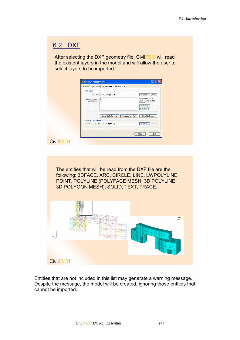
6.1. Introduction
CivilFEM INTRO. Essential 144
6.2 DXF
After selecting the DXF geometry file, CivilFEM will read the existent layers in the model and will allow the user to select layers to be imported:
The entities that will be read from the DXF file are the following: 3DFACE, ARC, CIRCLE, LINE, LWPOLYLINE, POINT, POLYLINE (POLYFACE MESH, 3D POLYLINE, 3D POLYGON MESH), SOLID, TEXT, TRACE.
Entities that are not included in this list may generate a warning message. Despite the message, the model will be created, ignoring those entities that cannot be imported.
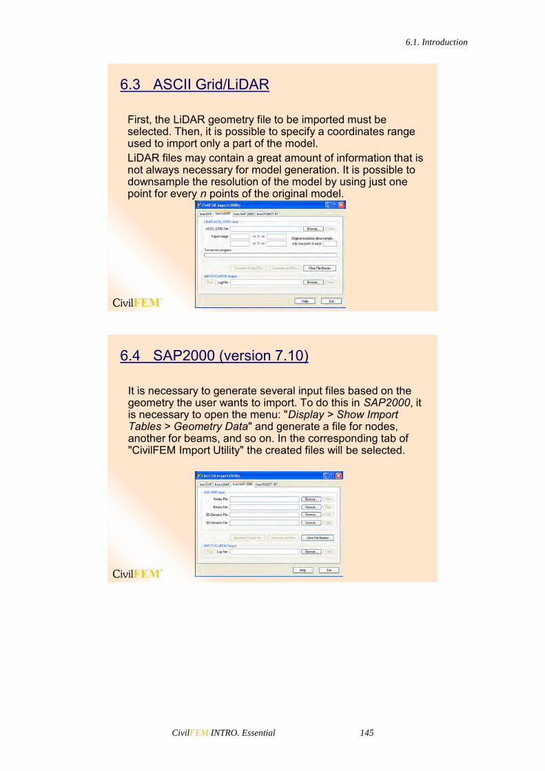
6.1. Introduction
CivilFEM INTRO. Essential 145
6.3 ASCII Grid/LiDAR
First, the LiDAR geometry file to be imported must be selected. Then, it is possible to specify a coordinates range used to import only a part of the model.LiDAR files may contain a great amount of information that is not always necessary for model generation. It is possible to downsample the resolution of the model by using just one point for every n points of the original model.
6.4 SAP2000 (version 7.10)
It is necessary to generate several input files based on the geometry the user wants to import. To do this in SAP2000, it is necessary to open the menu: "Display > Show Import Tables > Geometry Data" and generate a file for nodes, another for beams, and so on. In the corresponding tab of "CivilFEM Import Utility" the created files will be selected.

6.1. Introduction
CivilFEM INTRO. Essential 146
6.5 ROBOT MILLENIUM 97
For this program it is necessary to generate only one input file with geometry that will be exported. To do this, in Robot Millenium, the file must be saved in text format, with extension "*.STR" (instead of the extension "*.RTD" of Robot). In the corresponding tab of "CivilFEM Import Utility" the created file must be selected:

6.1. Introduction
CivilFEM INTRO. Essential 147
7 Coordinate System

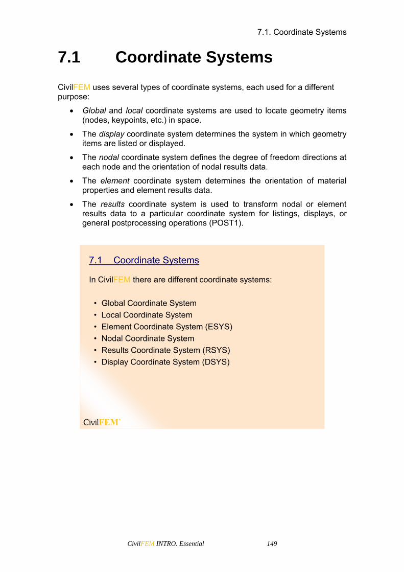
7.1. Coordinate Systems
CivilFEM INTRO. Essential 149
7.1 Coordinate Systems
CivilFEM uses several types of coordinate systems, each used for a different purpose:
Global and local coordinate systems are used to locate geometry items (nodes, keypoints, etc.) in space.
The display coordinate system determines the system in which geometry items are listed or displayed.
The nodal coordinate system defines the degree of freedom directions at each node and the orientation of nodal results data.
The element coordinate system determines the orientation of material properties and element results data.
The results coordinate system is used to transform nodal or element results data to a particular coordinate system for listings, displays, or general postprocessing operations (POST1).
In CivilFEM there are different coordinate systems:
• Global Coordinate System• Local Coordinate System• Element Coordinate System (ESYS)• Nodal Coordinate System• Results Coordinate System (RSYS)• Display Coordinate System (DSYS)
7.1 Coordinate Systems
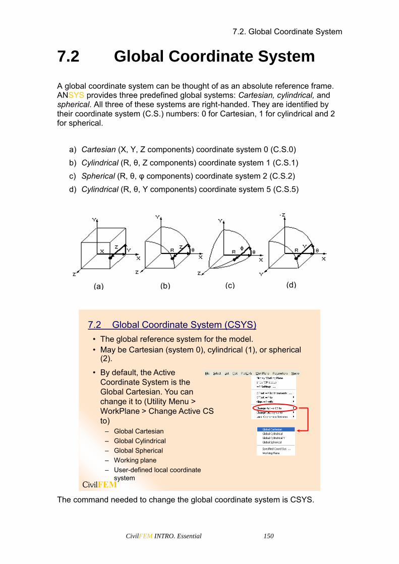
7.2. Global Coordinate System
CivilFEM INTRO. Essential 150
7.2 Global Coordinate System
A global coordinate system can be thought of as an absolute reference frame. ANSYS provides three predefined global systems: Cartesian, cylindrical, and spherical. All three of these systems are right-handed. They are identified by their coordinate system (C.S.) numbers: 0 for Cartesian, 1 for cylindrical and 2 for spherical.
a) Cartesian (X, Y, Z components) coordinate system 0 (C.S.0) b) Cylindrical (R, θ, Z components) coordinate system 1 (C.S.1) c) Spherical (R, θ, φ components) coordinate system 2 (C.S.2) d) Cylindrical (R, θ, Y components) coordinate system 5 (C.S.5)
7.2 Global Coordinate System (CSYS)• The global reference system for the model.• May be Cartesian (system 0), cylindrical (1), or spherical
(2).
• By default, the Active Coordinate System is the Global Cartesian. You can change it to (Utility Menu > WorkPlane > Change Active CS to)
– Global Cartesian– Global Cylindrical– Global Spherical– Working plane– User-defined local coordinate
system
The command needed to change the global coordinate system is CSYS.
(d) (c) (a) (b)
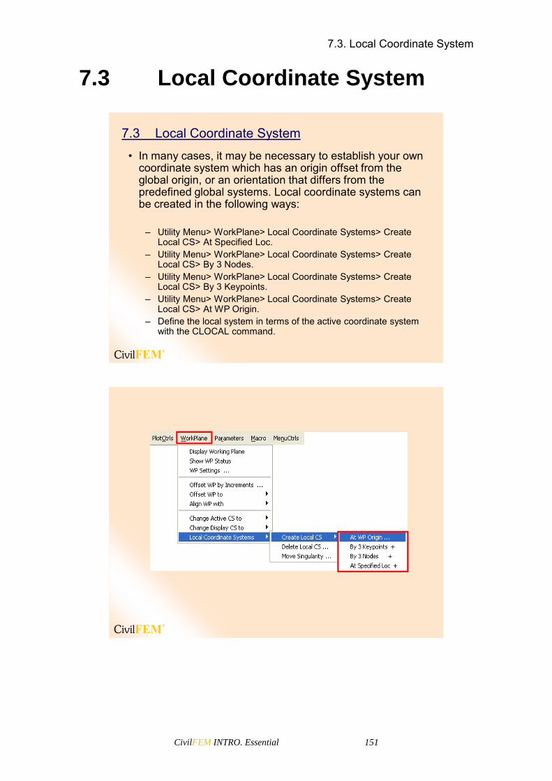
7.3. Local Coordinate System
CivilFEM INTRO. Essential 151
7.3 Local Coordinate System
7.3 Local Coordinate System
• In many cases, it may be necessary to establish your own coordinate system which has an origin offset from the global origin, or an orientation that differs from the predefined global systems. Local coordinate systems can be created in the following ways:
– Utility Menu> WorkPlane> Local Coordinate Systems> Create Local CS> At Specified Loc.
– Utility Menu> WorkPlane> Local Coordinate Systems> Create Local CS> By 3 Nodes.
– Utility Menu> WorkPlane> Local Coordinate Systems> Create Local CS> By 3 Keypoints.
– Utility Menu> WorkPlane> Local Coordinate Systems> Create Local CS> At WP Origin.
– Define the local system in terms of the active coordinate system with the CLOCAL command.

7.4. Element Coordinate System
CivilFEM INTRO. Essential 152
• When a local coordinate system is defined, it becomes the active coordinate system. As you create a local system, you assign it a CSYS identification number (which must be 11 or greater).
• You can create (or delete) local coordinate systems in any phase of your ANSYS session. To delete a local system, use the following method:
– Utility Menu> WorkPlane> Local Coordinate Systems> Delete Local CS
• Local coordinate systems can be Cartesian, Cylindrical or Spherical.
7.4 Element Coordinate System
7.4 Element Coordinate System (ESYS)
• Every element has its own coordinate system that determines the direction of orthotropic material properties, applied pressures, and results (such as stresses and strains) for that element. All element coordinate systems are right-handed orthogonal systems.
• The default ESYS orientation is described in the Help document for each element type.
• Many element types have key options that allow you to change the default element coordinate system orientation. For area and volume elements, you can also change the orientation to align the element coordinate system with a previously defined local system by using one of the following methods:
To change the default ESYS, it is necessary to align it with a specified local coordinate system (CSYS 11 or greater).
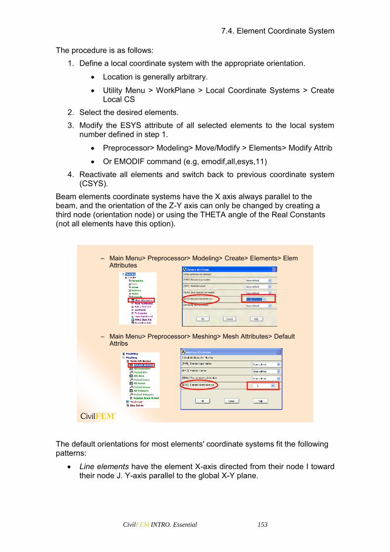
7.4. Element Coordinate System
CivilFEM INTRO. Essential 153
The procedure is as follows: 1. Define a local coordinate system with the appropriate orientation.
Location is generally arbitrary.
Utility Menu > WorkPlane > Local Coordinate Systems > Create Local CS
2. Select the desired elements. 3. Modify the ESYS attribute of all selected elements to the local system
number defined in step 1.
Preprocessor> Modeling> Move/Modify > Elements> Modify Attrib
Or EMODIF command (e.g, emodif,all,esys,11) 4. Reactivate all elements and switch back to previous coordinate system
(CSYS). Beam elements coordinate systems have the X axis always parallel to the beam, and the orientation of the Z-Y axis can only be changed by creating a third node (orientation node) or using the THETA angle of the Real Constants (not all elements have this option).
– Main Menu> Preprocessor> Meshing> Mesh Attributes> Default Attribs
– Main Menu> Preprocessor> Modeling> Create> Elements> Elem Attributes
The default orientations for most elements' coordinate systems fit the following patterns:
Line elements have the element X-axis directed from their node I toward their node J. Y-axis parallel to the global X-Y plane.

7.5. Nodal Coordinate System
CivilFEM INTRO. Essential 154
Shell elements: - element X from node I to node J - element Y perpendicular to element X in the plane of the element - element Z normal to X-Y by right-hand rule
For 2-D and 3-D solid elements, the element coordinate system is usually parallel to the global Cartesian system.
7.5 Nodal Coordinate System
7.5 Nodal Coordinate System
• While global and local coordinate systems locate geometry items, the nodal coordinate system orients the degree of freedom directions at each node. Each node has its own nodal coordinate system, which by default, is parallel to global Cartesian. You can rotate the nodal coordinate system at any node to a desired orientation using one of the following methods:
– Main Menu> Preprocessor> Modeling> Move/Modify> RotateNode CS> To Active CS
– Main Menu> Preprocessor> Modeling> Move/Modify> RotateNode CS> By Angles
– Main Menu> Preprocessor> Modeling> Move/Modify> RotateNode CS> By Vectors

7.6. Results Coordinate System
CivilFEM INTRO. Essential 155
7.6 Results Coordinate System
7.6 Results Coordinate System (RSYS)
• Results data are calculated during solution and consist of displacements, stresses, strains, etc. These data are stored in the database and in the results file in either the nodal coordinate system or the element coordinate system. However, results data are generally rotated into the active results coordinate system (which is by default the global Cartesian system) for displays, listings, and element table data storage.
• It is possible to change the active results coordinate system to another system:
– Main Menu> General Postproc> Options for Output

7.7. Display Coordinate System
CivilFEM INTRO. Essential 156
7.7 Display Coordinate System
7.7 Display Coordinate System (DSYS)
• By default, a listing of nodes or keypoints always shows their global Cartesian coordinates, even if they were defined in a different coordinate system. You can change the display coordinate system used in such listings by one of the following methods:
– Utility Menu> WorkPlane> Change Display CS to> Global Cartesian
– Utility Menu> WorkPlane> Change Display CS to> Global Cylindrical
– Utility Menu> WorkPlane> Change Display CS to> Global Spherical
– Utility Menu> WorkPlane> Change Display CS to> Specified Coord Sys
• Changing the display coordinate system will also affect your graphical displays.

CivilFEM INTRO. Essential 157
8 Element types

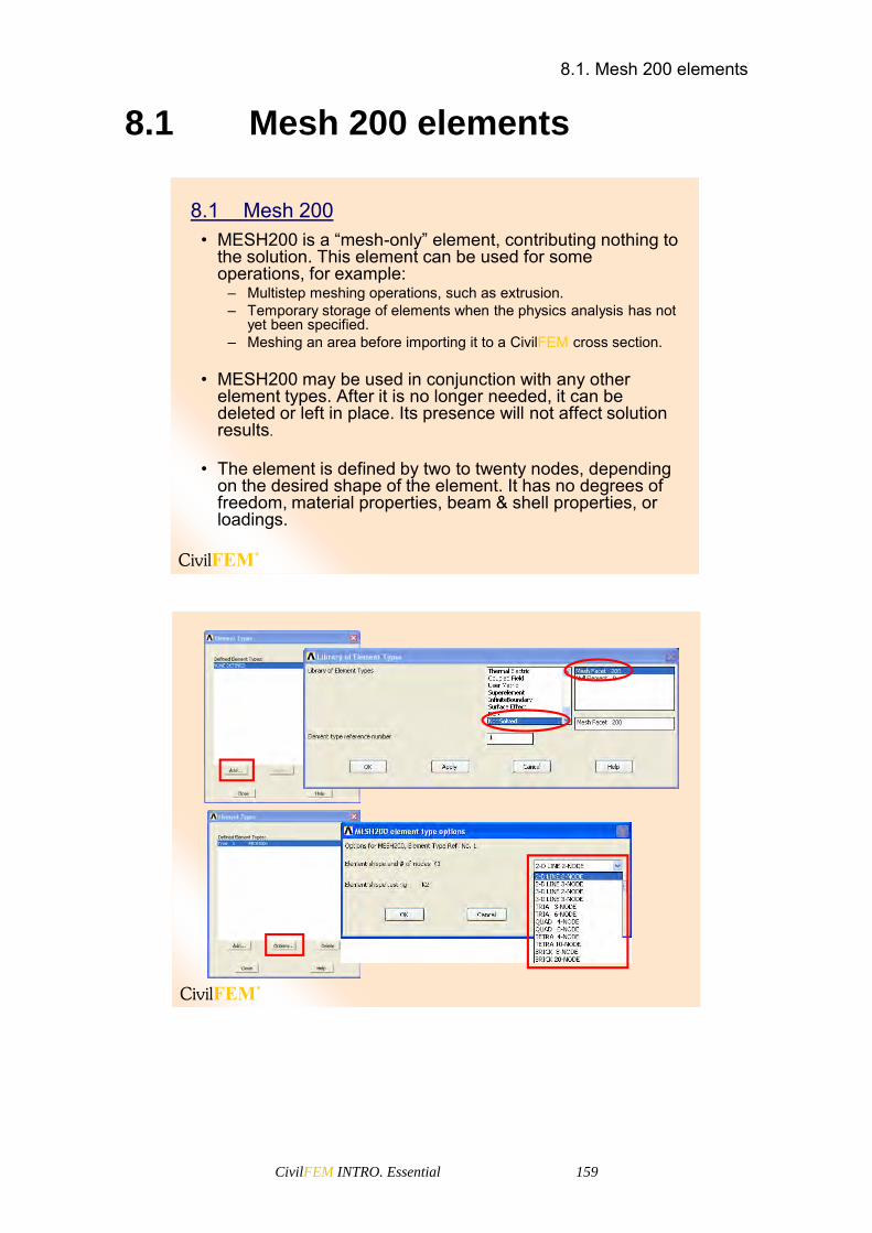
8.1. Mesh 200 elements
CivilFEM INTRO. Essential 159
8.1 Mesh 200 elements
8.1 Mesh 200• MESH200 is a “mesh-only” element, contributing nothing to
the solution. This element can be used for some operations, for example:
– Multistep meshing operations, such as extrusion.– Temporary storage of elements when the physics analysis has not
yet been specified.– Meshing an area before importing it to a CivilFEM cross section.
• MESH200 may be used in conjunction with any other element types. After it is no longer needed, it can be deleted or left in place. Its presence will not affect solution results.
• The element is defined by two to twenty nodes, depending on the desired shape of the element. It has no degrees of freedom, material properties, beam & shell properties, or loadings.

8.2. Surface elements
CivilFEM INTRO. Essential 160
8.2 Surface elements
8.2 Surface elements
• How would you apply a pressure load, that is:– tangential to the surface, such as a shear load?– spatially varying over the surface, such as a bolt load?– oriented at an angle to the surface, such as ice load on a rooftop?
• Surface effect elements provide an effective way to do this.
Characteristics:• They overlay the surface of an underlying mesh like a
“skin.”• They act as a conduit for surface loads.• Creating them is very easy:
– Select nodes on the surface of interest and at least the elements attached to them.
– Activate the appropriate element type.– Issue ESURF (or Preprocessor > Create > Elements > Surf /
Contact > Surf Effect…).– Select all nodes.

8.2. Surface elements
CivilFEM INTRO. Essential 161
• Available for both 2-D and 3-D models:– SURF151 & 153 are line elements (thermal and structural) meant
for edges of 2D models.– SURF152 & 154 are area elements (thermal and structural) meant
for surfaces of 3D models.– SURF156 are 3D line elements (structural) meant for edges of 3D
models.• We will discuss only SURF154 in this section, but the
same concepts can be applied to the other elements.
SURF154 as depicted in the Elements
Reference manual

8.2. Surface elements
CivilFEM INTRO. Essential 162
• SURF154 uses different element face numbers to accept different types of loads.
• The face number is a field in the "Apply PRES on elems" dialog (Solution > Define Loads > Apply > Structural > Pressures > On Elements), as shown below.
• The orientation of the pressure depends on which element face is used.
• Faces 2 & 3:– Tangential pressures, along
element X & Y respectively.
• Face 1:– Normal pressure.– Positive value acts into the
element (along element -Z).

8.2. Surface elements
CivilFEM INTRO. Essential 163
• Face 4:– Normal pressure, tapered. Magnitude = P1 + XgP2 + YgP3 + ZgP4
– P1-P4 are specified VAL1-VAL4 on SFE command.– Xg,Yg, Zg are the global Cartesian locations of the element's
integration points.– P2,P3,P4 are the slopes in global X,Y,Z respectively and default to
P1 if left blank.– Positive value acts into the element (along element -Z).
Xg
P2
Xg=0
P1
– For example, to apply a tapered pressure of 200 to 1000 in the global X direction, with X values ranging from -2 to +2: Slope P2 = (1000-200)/4 = 200; P3 = 0; P4 = 0 P1 is the value at Xg=0, calculated as P1 = 2(200) + 200 = 600 sfe,eflat,4,pres,,600,200,0,0

8.2. Surface elements
CivilFEM INTRO. Essential 164
• Face 5– Vector-oriented pressure of magnitude P1.
– Direction =
– P2,P3,P4 now represent the direction cosines of the vector and have no effect on the magnitude.
– Example: sfe,eflat,5,pres,,1000,-1,-1,0 defines a pressure at angle of 45° in the X-Y plane.
24
23
22
g4g3g2
PPP
ZPYPXP
– The magnitude of vector-oriented pressure also depends on KEYOPT(11).
– KEYOPT(11)=0 (default) and 1 applies pressure on the projected area of surface elements.
– Useful for bolt loading (or pin loading).– Example: sfe,ecurv,5,pres,,1000,0,-1,0 defines a bolt load on the
curved surface, as shown by a POST1 contour plot below.

8.2. Surface elements
CivilFEM INTRO. Essential 165
– KEYOPT(11)=2 applies pressure on the full area. Useful for inclined surfaces (such as a roof top) or wind loads. Example: sfe,eslope,5,pres,,1000,0,-1,0 defines uniform, full
pressure on all faces of an inclined surface, as shown below.
Surface Elements Example
The aim of this simple example is to become familiar with surface elements. First, the surface and solid elements must be selected from ANSYS library.
Main Menu> Preprocessor> Element type> Add/Edit/Delete
Elements to be selected: 3D Structural154 (1) and Solid45 (2)
Second, the material for the model is selected from CivilFEM material library.
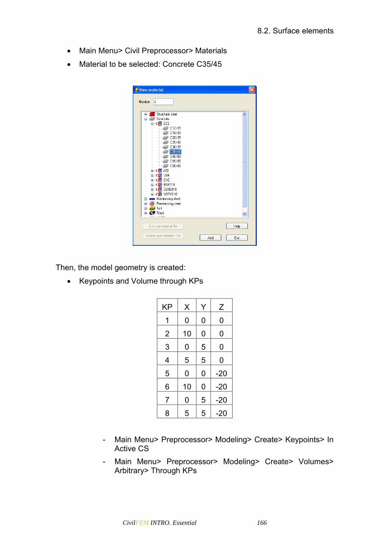
8.2. Surface elements
CivilFEM INTRO. Essential 166
Main Menu> Civil Preprocessor> Materials
Material to be selected: Concrete C35/45
Then, the model geometry is created:
Keypoints and Volume through KPs
KP X Y Z
1 0 0 0
2 10 0 0
3 0 5 0
4 5 5 0
5 0 0 -20
6 10 0 -20
7 0 5 -20
8 5 5 -20
- Main Menu> Preprocessor> Modeling> Create> Keypoints> In
Active CS - Main Menu> Preprocessor> Modeling> Create> Volumes>
Arbitrary> Through KPs

8.2. Surface elements
CivilFEM INTRO. Essential 167
Finally, generate the mesh (Main Menu> Preprocessor> Meshing> Mesh Tool):
First, change the attributes: select the solid45 element
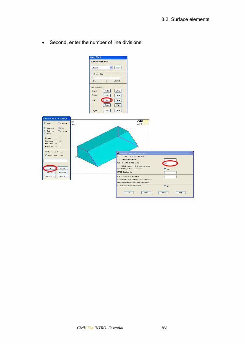
8.2. Surface elements
CivilFEM INTRO. Essential 168
Second, enter the number of line divisions:

8.2. Surface elements
CivilFEM INTRO. Essential 169
Third, select Hex and Mapped mesh and select the volume (the number of divisions in opposite lines must be the same).
Finally, generate the mesh.

8.2. Surface elements
CivilFEM INTRO. Essential 170
Now a tangential pressure in Y direction will be applied to elements with Z=0 coordinate.
First, select the nodes located at Z=0 (Utility menu> Select Entities…> Nodes by location)
Second, change the element attributes (Main Menu> Preprocessor> Modeling> Create> Elements> Elem Attributes)

8.2. Surface elements
CivilFEM INTRO. Essential 171
Then, create the surf elements (Main Menu> Preprocessor> Modeling> Create> Elements> Surf/Contact> Surf Effect> General Surface> No extra Node)
Finally, apply the pressure of 1000 Pa in the Y direction:
Select the elements by the number of element. (number 1) (Utility Menu> Select> Entities…> Elements by attributes> Element type number)
Apply the pressure (Main Menu> Solution> Define Loads> Apply> Structural> Pressure> On elements: Pick all). The Face number must be number 3; this indicates a tangential pressure in the Y direction.
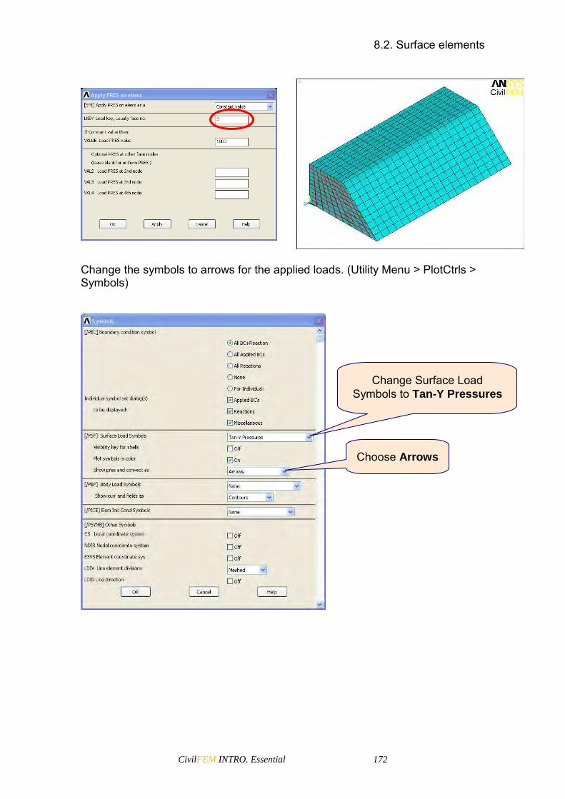
8.2. Surface elements
CivilFEM INTRO. Essential 172
Change the symbols to arrows for the applied loads. (Utility Menu > PlotCtrls > Symbols)
Change Surface Load Symbols to Tan-Y Pressures
Choose Arrows
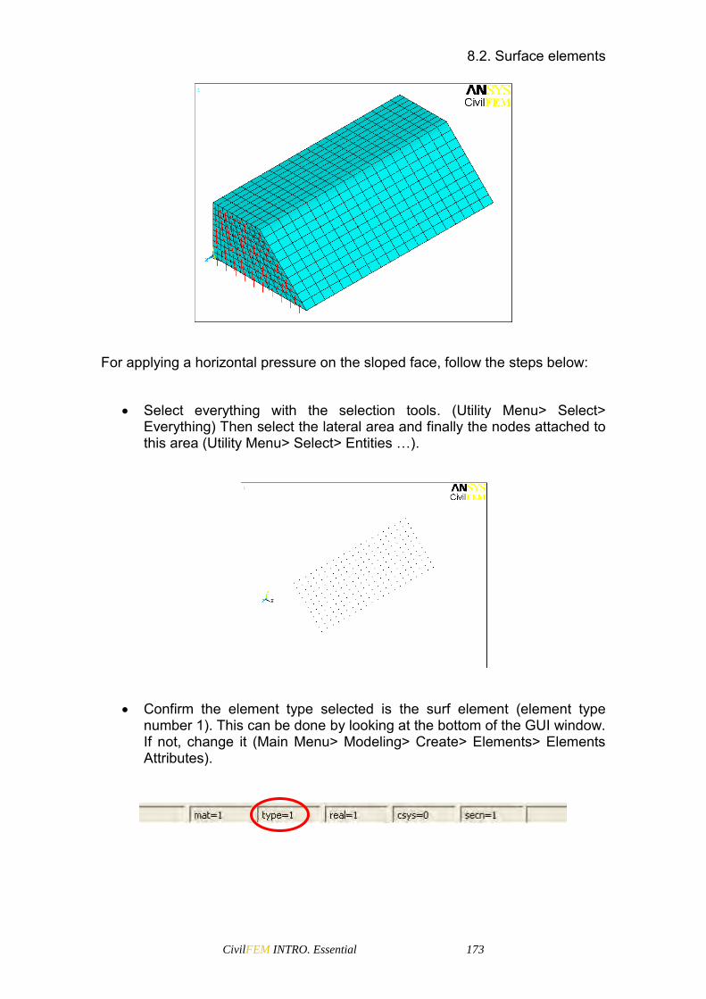
8.2. Surface elements
CivilFEM INTRO. Essential 173
For applying a horizontal pressure on the sloped face, follow the steps below:
Select everything with the selection tools. (Utility Menu> Select> Everything) Then select the lateral area and finally the nodes attached to this area (Utility Menu> Select> Entities …).
Confirm the element type selected is the surf element (element type number 1). This can be done by looking at the bottom of the GUI window. If not, change it (Main Menu> Modeling> Create> Elements> Elements Attributes).

8.2. Surface elements
CivilFEM INTRO. Essential 174
Then, create the surface elements (Main Menu> Preprocessor> Modeling> Create> Elements> Surf/Contact> Surf Effect> General Surface> No extra Node).
Finally, select these created elements and apply the pressure of 1000 Pa in the –X direction. (Main Menu> Solution> Define Loads> Apply> Structural> Pressure> On elements: Pick all)
These values indicate the direction of the load vector
The load key indicates the way to apply the load

8.3. Contact Elements
CivilFEM INTRO. Essential 175
The KEYOPTION 11 is 0 by default, so the pressure is applied on the projected area. If the pressure is to be applied on the full area, the KEYOPTION 11 in element type options is required to be changed when the SURF154 element is defined:
8.3 Contact Elements
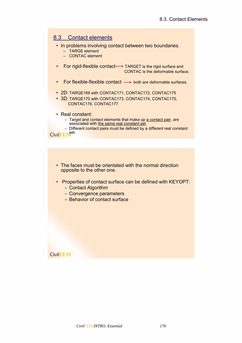
8.3. Contact Elements
CivilFEM INTRO. Essential 176
8.3 Contact elements• In problems involving contact between two boundaries.
– TARGE element– CONTAC element
• For rigid-flexible contact TARGET is the rigid surface andCONTAC is the deformable surface.
• For flexible-flexible contact both are deformable surfaces.
• 2D: TARGE169 with CONTAC171, CONTAC172, CONTAC175 • 3D: TARGE170 with CONTAC173, CONTAC174, CONTAC175,
CONTAC176, CONTAC177
• Real constant:‒ Target and contact elements that make up a contact pair, are
associated with the same real constant set.‒ Different contact pairs must be defined by a different real constant
set.
• The faces must be orientated with the normal direction opposite to the other one.
• Properties of contact surface can be defined with KEYOPT:‒ Contact Algorithm‒ Convergence parameters‒ Behavior of contact surface

CivilFEM INTRO. Essential 177
9 CivilFEM Materials


9.1. CivilFEM and ANSYS Materials Coupling
CivilFEM INTRO. Essential 179
9.1 CivilFEM and ANSYS Materials Coupling
Material properties defined by CivilFEM include ANSYS standard properties as well as other properties necessary for CivilFEM specific calculations, such as properties related to codes: characteristics strengths, yield strengths, reduction coefficients, etc.
• CivilFEM materials are linked to those in ANSYS so that the number identifying the CivilFEM material corresponds to the number of the material in ANSYS.
• The definition of a material in CivilFEM implies the automatic definition of the ANSYS material properties and the data required for CivilFEM postprocess.
• When deleting or modifying a material with CivilFEMcommands, the corresponding ANSYS material is also deleted or modified.
• It is not recommended to define nor delete the material properties using ANSYS, as CivilFEM material properties will not be defined or modified.
9.1 CivilFEM and ANSYS Materials Coupling

9.2. Materials definition
CivilFEM INTRO. Essential 180
9.2 Materials definition
• Define materials by the following this menu path:– Main Menu > Civil Preprocessor > Materials
Some materials in CivilFEM are time
dependent
9.2 Materials definition
CivilFEM material definition (see CFMP command in CivilFEM Help) is achieved by selecting one of the materials included in its libraries.
• CivilFEM material library defines the following material types:
– Structural Steel– Concrete– Reinforcing Steel– Prestressing Steel (*)– Soils (*)– Rocks (*)
(*) Described in the Training for the Specialized Modules
When selecting a material from the library all properties are
automatically defined

9.2. Materials definition
CivilFEM INTRO. Essential 181
• The material properties are divided into different groups of properties.
– General properties: common for all materials (number, reference, type, properties for elastic analysis, ...)
– Analysis and design diagrams– Material properties: Specific for steel, concrete, etc.– Code properties: Specific for the code selected in the
configuration menu, etc.– FLAC3D properties: Only for exporting the model to FLAC3D
CivilFEM material properties are time dependent. This dependency is controlled by a global variable called active time (see ACTTIME command). This time is common to all materials and its value is fixed by the user in each instant. CivilFEM active time may or may not coincide with ANSYS time (ANSYS TIME command). On the other hand, each CivilFEM material contains the material’s activation time and controls when the materials are initially activiated. Once active time and activation time are established, those materials whose activation time is the same or less than the active time will be active. Those elements of a section whose material is inactive do not exist to any effect (either in CivilFEM or in ANSYS). The age of each material is calculated for each instant from the active time (ActTime) and activation instant values:
MatAge (Imat) = ActTime – TmAct (Imat) Where:
MatAge: Material Age ActTime: Active Time TmAct: Material’s activation time Imat: Material taken into account
This age allows the calculation of any property of the material in the considered instant by interpolation of the respective time dependent vectors.
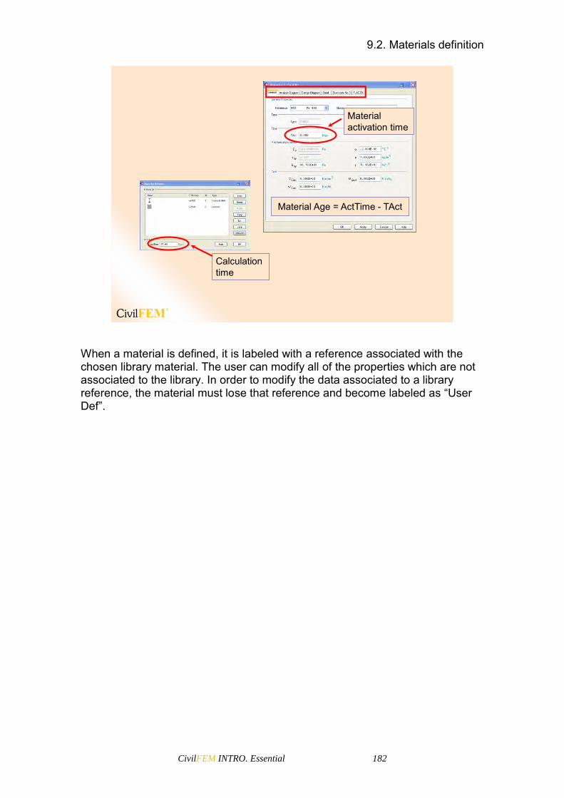
9.2. Materials definition
CivilFEM INTRO. Essential 182
Material activation time
Material Age = ActTime - TAct
Calculation time
When a material is defined, it is labeled with a reference associated with the chosen library material. The user can modify all of the properties which are not associated to the library. In order to modify the data associated to a library reference, the material must lose that reference and become labeled as “User Def”.

9.3. Structural Steel Material Properties
CivilFEM INTRO. Essential 183
9.3 Structural Steel Material Properties
General Properties
• All CivilFEM material properties may be modified if the User Def option is activated.
• General Properties are divided into:
– General properties– Type– Time– Mechanical properties– Cost
User Def option
Material name
General Properties9.3 Structural Steel Material Properties
The command ~CFMP defines Structural Steel Material Properties in CivilFEM and ANSYS. It can be used with one of the options below:
From Library: Data associated with a library reference.
User defined: The material loses its library reference and the user can modify all the properties.

9.3. Structural Steel Material Properties
CivilFEM INTRO. Essential 184
Analysis and Design Diagrams
• Analysis Diagram is the stress-strain diagram used for the structural analysis of the model. If the option User Def is activated, the user will be able to add or delete diagram points.
• Code dependent stress-strain diagrams exist for different material thicknesses. In addition, the diagram may be displayed in tension, compression or tension and compression.
Type of diagram
Type of plot
Diagram points
Material thickness
Analysis Diagram
Non-Linear Behavior
Design Diagram
• Design Diagram is the stress-strain diagram used for the section’s analysis. If the option User Def is activated, the user will be able to add or delete diagram points.
• Code dependent stress-strain diagrams exist for the different material thicknesses. In addition, the diagram may be displayed in tension, compression or tension and compression.
It is possible to modify the diagrams by previously changing the field Type to 0: User Defined. Depending on the type of diagram, different non-linear behaviours can be selected (KPLA property).

9.3. Structural Steel Material Properties
CivilFEM INTRO. Essential 185
Depending on the active code, the material properties may depend on the thickness of the steel plate. The variation of the properties that depend on the thickness can be seen by selecting the thickness range on the bottom buttons.
Steel Properties
The material type window will vary according to the selected material and active code.
Steel Properties• Steel properties are properties related to the steel material
only. If the option User Def is selected, the user will be able to change the material thickness as well as the modulus of elasticity.
• Steel properties include:– Thickness dependent
properties– Linear structural properties– ANSYS plastic behavior– Strain limits
Thickness definition
Strain limits
Code Properties
The code window will vary according to the selected material and active code.

9.4. Concrete Material Properties
CivilFEM INTRO. Essential 186
Code Properties
Properties related to the active steel code.
Mechanical properties
Safety factorsaccording to code
9.4 Concrete Material Properties
General Properties
9.4 Concrete Material Properties
• You can select one of the materials from the library and all the properties will be automatically defined. You can also modify all the properties by the User Def option.
– Define material properties from library
Actual calculation time

9.4. Concrete Material Properties
CivilFEM INTRO. Essential 187
– User Defined:You can define a material from the library and then modify it, changing its reference to “User Def”.
Material Birth Time
After changing its properties, you can save
the material into the user material library.
Analysis Diagram
Analysis Diagram
• The analysis diagram is the stress-strain curve that will be used by ANSYS for the structural analysis of the model.
• It is possible to define the real stress-strain analysis diagrams of the materials using the pre-established for the active code or to modify these diagrams by adding or deleting points with the option user defined.
One stress-strain curve for each age
Non-Linear Behavior

9.4. Concrete Material Properties
CivilFEM INTRO. Essential 188
Design Diagram
The design diagram is the stress-strain curve that is used by CivilFEM for section’s check and design.
Design Diagram
Choose the stress-strain diagram type or define it by adding or deleting points.
Concrete properties and code properties
Concrete properties and code propertiesIt is possible to add, delete or modify the existing ages of the material. All material properties are automatically calculated for the additional ages.
Age dependent properties
With time dependent materials, the user has the option to plot the evolution of certain properties through time by clicking with the right mouse button on the name of the property:

9.4. Concrete Material Properties
CivilFEM INTRO. Essential 189

9.5. Reinforcing Steel Material Properties
CivilFEM INTRO. Essential 190
9.5 Reinforcing Steel Material Properties
The ~CFMP command defines all reinforcing steel material properties including the properties necessary to carry out an ANSYS analysis.
9.5 Reinforcing Steel Material Properties
• You can select a type of reinforcing steel from the library of materials and all the properties will automatically defined. You can also modify all of the properties by the User Def option.
– Define material properties from library:
– User Defined:You can define a material from the library and then modify it, changing its reference to “User Def”.
After changing its properties, you can save
the material into the user material library.

9.6. User Material Library
CivilFEM INTRO. Essential 191
9.6 User Material Library
After modifying a material, it can be saved for future sessions of CivilFEM. To do this, press the Save button on the material browser window. The name of the file where the material will be stored must be specified in the Database FileName field. If the file does not exist, it will be created, and if it already exists, the material will be added to the file. The name of the file will be the name of the folder that will appear inside the USER group of materials, and it will contain all the materials stored in it. To use the saved materials in a different computer, it is only necessary to copy the file or files that contain the materials to the respective folder on the other computer.
9.6 User Material Library
• It is possible to add user materials into the CivilFEMmaterial library by:
– Selecting a material from the library– Modifying its properties (User Def)– Storing it in a file named by the user
The name of the file to be created must be specified
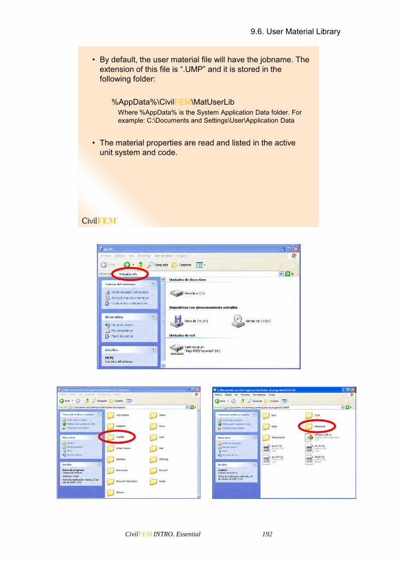
9.6. User Material Library
CivilFEM INTRO. Essential 192
• By default, the user material file will have the jobname. The extension of this file is “.UMP” and it is stored in the following folder:
%AppData%\CivilFEM\MatUserLibWhere %AppData% is the System Application Data folder. For example: C:\Documents and Settings\User\Application Data
• The material properties are read and listed in the active unit system and code.

9.6. User Material Library
CivilFEM INTRO. Essential 193
To delete a saved material, select the material and press the button Delete material/file. To delete a whole file, all of the materials it contains must be deleted first. Once it is empty it is possible to delete it by selecting it and pressing the Delete material/file.
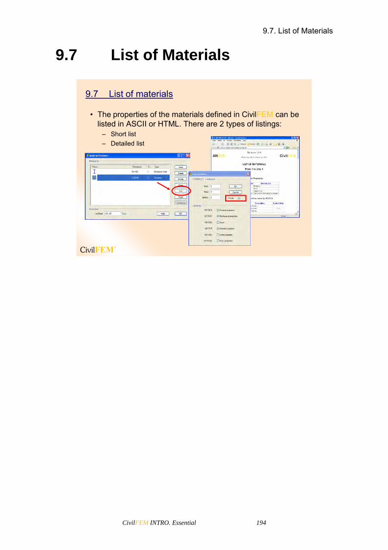
9.7. List of Materials
CivilFEM INTRO. Essential 194
9.7 List of Materials
9.7 List of materials
• The properties of the materials defined in CivilFEM can be listed in ASCII or HTML. There are 2 types of listings:
– Short list– Detailed list

CivilFEM INTRO. Essential 195
10 CivilFEM Cross Sections


10.1. Cross Section concept
CivilFEM INTRO. Essential 197
10.1 Cross Section concept
This concept refers to a unique cross section, as commonly understood in engineering. There are many ways of defining cross sections with CivilFEM using the cross section explorer.
– Main Menu> Civil Preprocessor> Cross Section
In this window we can see a list of all the defined cross sections
10.1 Cross Section concept
10.2 Steel Cross Sections
10.2 Steel Cross Sections
• A steel cross can be defined in five different ways:
– Library of hot rolled shapes – Steel beams by dimensions– Steel sections by plates– Section merge– Capture 2D mesh

10.2. Steel Cross Sections
CivilFEM INTRO. Essential 198
Hot Rolled Shapes Library
To select the desired section, the user must find the section in the shapes library, located in the left side of the window. This library contains all the shapes classified in CivilFEM.
Hot Rolled Shapes Library
Section properties.More properties are
available through listing
Section dimensions
Add shapes into the library
Search option
Apply+Exit
“ANSYS and CivilFEMproperties will be
automatically defined according to active units”
In the top right corner of the window, the user may find the Search button (Find).
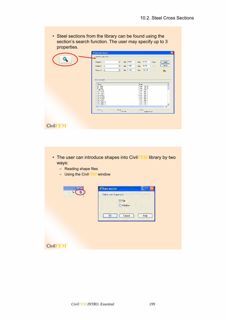
10.2. Steel Cross Sections
CivilFEM INTRO. Essential 199
• Steel sections from the library can be found using the section’s search function. The user may specify up to 3 properties.
• The user can introduce shapes into CivilFEM library by two ways:
– Reading shape files– Using the CivilFEM window

10.2. Steel Cross Sections
CivilFEM INTRO. Essential 200
• The user data files for hot rolled shapes are stored in the following folder:
%AppData%\CivilFEM\ShapeUserLibWhere %AppData% is the System Application Data folder.
• The files extensions are .bin .mec (mechanical properties) and .geo (geometrical properties).

10.2. Steel Cross Sections
CivilFEM INTRO. Essential 201
Reading files: The user must specify the files (the geometricdata file and the mechanical properties file) needed to importthe new shapes. If the mechanical data are not available,CivilFEM will calculate them automatically from the definedgeometry.

10.2. Steel Cross Sections
CivilFEM INTRO. Essential 202
CivilFEM Window. The user must specify the necessaryparameters to define the new shape.
The group number must be between 501 and 999
Steel Sections by Dimensions
In this window, steel sections by dimensions may be created. To do so, the type of section must be previously selected. The different types of sections supported by CivilFEM are the following:
I
C
T
L
PIPE
BOX
After defining the type of section, the desired values are introduced in the corresponding boxes. To identify the notation used in the section’s geometry, the user may consult the figure attached in the bottom left corner of the screen.
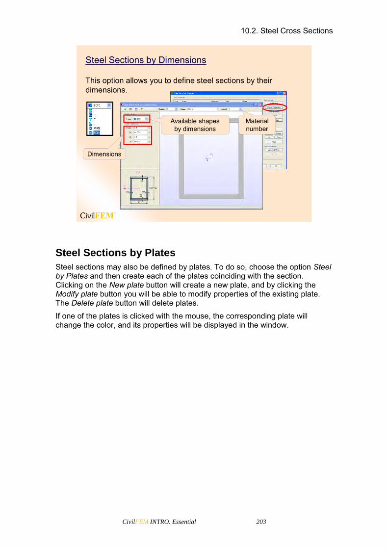
10.2. Steel Cross Sections
CivilFEM INTRO. Essential 203
Steel Sections by Dimensions
This option allows you to define steel sections by their dimensions.
Available shapesby dimensions
Material number
Dimensions
Steel Sections by Plates
Steel sections may also be defined by plates. To do so, choose the option Steel by Plates and then create each of the plates coinciding with the section. Clicking on the New plate button will create a new plate, and by clicking the Modify plate button you will be able to modify properties of the existing plate. The Delete plate button will delete plates. If one of the plates is clicked with the mouse, the corresponding plate will change the color, and its properties will be displayed in the window.
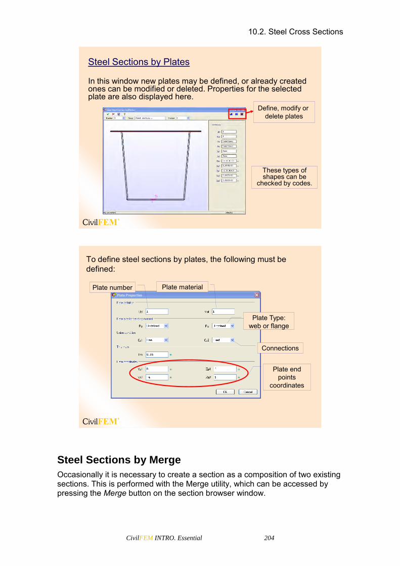
10.2. Steel Cross Sections
CivilFEM INTRO. Essential 204
Steel Sections by Plates
In this window new plates may be defined, or already created ones can be modified or deleted. Properties for the selected plate are also displayed here.
Define, modify or delete plates
These types of shapes can be
checked by codes.
To define steel sections by plates, the following must be defined:
Plate number Plate material
Plate Type: web or flange
Connections
Plate end points
coordinates
Steel Sections by Merge
Occasionally it is necessary to create a section as a composition of two existing sections. This is performed with the Merge utility, which can be accessed by pressing the Merge button on the section browser window.
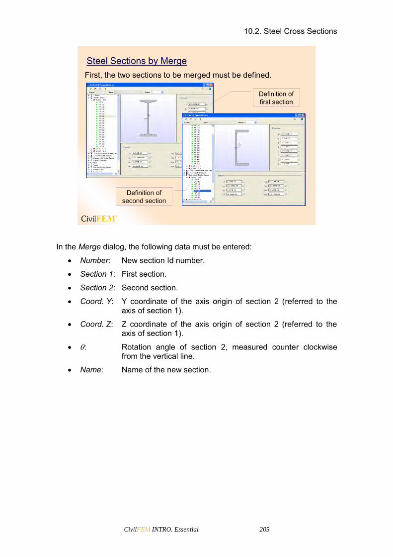
10.2. Steel Cross Sections
CivilFEM INTRO. Essential 205
Steel Sections by MergeFirst, the two sections to be merged must be defined.
Definition of first section
Definition of second section
In the Merge dialog, the following data must be entered:
Number: New section Id number.
Section 1: First section.
Section 2: Second section.
Coord. Y: Y coordinate of the axis origin of section 2 (referred to the axis of section 1).
Coord. Z: Z coordinate of the axis origin of section 2 (referred to the axis of section 1).
: Rotation angle of section 2, measured counter clockwise from the vertical line.
Name: Name of the new section.

10.3. Concrete Cross Sections
CivilFEM INTRO. Essential 206
Finally merge the sections.
Section 3Coordinates of the section 1 respect to the section 2
The created section will maintain all the code properties of section 1 and will have all the points, tessella, faces, plates, reinforcement groups, etc. of the two initial sections.
10.3 Concrete Cross Sections
10.3 Concrete Cross Sections
It is possible to check and design reinforced concrete beams formed by any generic cross section under axial loading plus biaxial bending, shear, torsion and combined shear and torsion.
– Cross sections by dimensions
– Import/Export of a 2D mesh
– Merge sections

10.3. Concrete Cross Sections
CivilFEM INTRO. Essential 207
In this screen, concrete sections may be created by dimensions. To do so, the type of section must be selected (Shape). Possible section types are:
I
C
T
L
PIPE
BOX
After defining the section type, the desired values must be introduced in the corresponding boxes. To identify the notation used in the section’s geometry, the user may consult the figure attached in the bottom left corner of the screen.
This window allows you to define concrete sections by their dimensions, defining all of their properties automatically.
Available shapesby dimensions Material
number

10.3. Concrete Cross Sections
CivilFEM INTRO. Essential 208
Concrete sections by dimensions:
Rectangular Box T
Pipe Circular I
Faces
Faces
• Each reinforcement group is located on a face.• A single face may have different reinforcement groups
associated to simulate several reinforcement layers.• The face is a polygonal line defined by at least two
points.
1 2
3
4Reinforcement location
Face
• The reinforcement is located at the left of the face.

10.3. Concrete Cross Sections
CivilFEM INTRO. Essential 209
• To define or modify a face:Edit > Faces
Click on a face to select it
Modify a face
Create a face
A face does not need to be defined by all the points of the contour of the section; only the beginning and ending points of a straight line are needed. In fact, a face can be inside the section; it does not have to be on the border line of the section.
Tessella
Points
Face
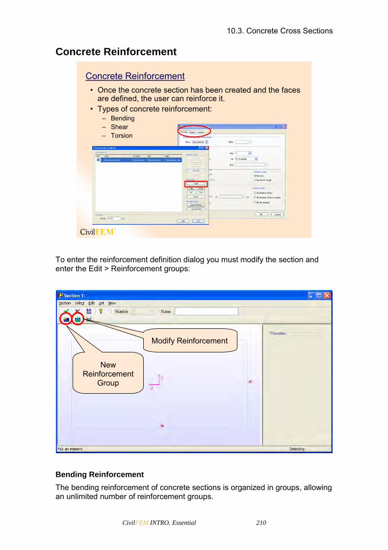
10.3. Concrete Cross Sections
CivilFEM INTRO. Essential 210
Concrete Reinforcement
Concrete Reinforcement• Once the concrete section has been created and the faces
are defined, the user can reinforce it.• Types of concrete reinforcement:
– Bending– Shear– Torsion
To enter the reinforcement definition dialog you must modify the section and enter the Edit > Reinforcement groups:
Bending Reinforcement
The bending reinforcement of concrete sections is organized in groups, allowing an unlimited number of reinforcement groups.
New Reinforcement
Group
Modify Reinforcement
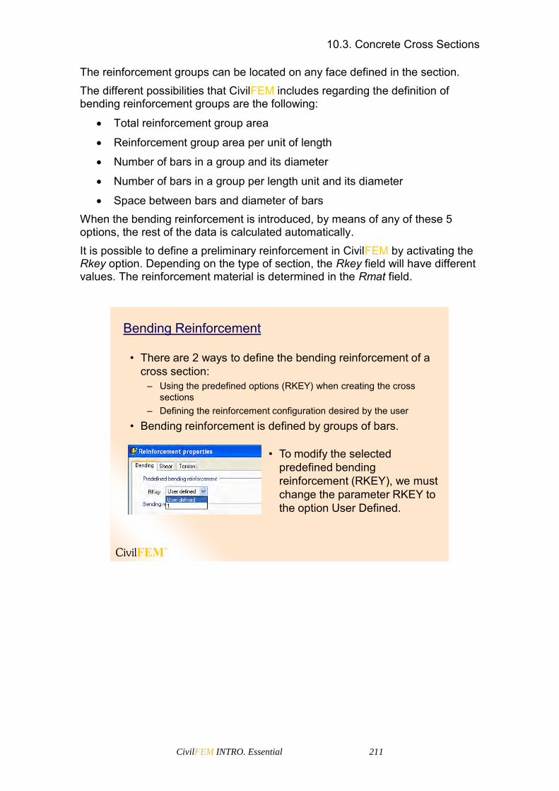
10.3. Concrete Cross Sections
CivilFEM INTRO. Essential 211
The reinforcement groups can be located on any face defined in the section. The different possibilities that CivilFEM includes regarding the definition of bending reinforcement groups are the following:
Total reinforcement group area
Reinforcement group area per unit of length
Number of bars in a group and its diameter
Number of bars in a group per length unit and its diameter
Space between bars and diameter of bars When the bending reinforcement is introduced, by means of any of these 5 options, the rest of the data is calculated automatically. It is possible to define a preliminary reinforcement in CivilFEM by activating the Rkey option. Depending on the type of section, the Rkey field will have different values. The reinforcement material is determined in the Rmat field.
Bending Reinforcement
• There are 2 ways to define the bending reinforcement of a cross section:
– Using the predefined options (RKEY) when creating the cross sections
– Defining the reinforcement configuration desired by the user
• Bending reinforcement is defined by groups of bars.
• To modify the selected predefined bending reinforcement (RKEY), we must change the parameter RKEY to the option User Defined.

10.3. Concrete Cross Sections
CivilFEM INTRO. Essential 212
RKEY options:
Box
GROUP 3 GROUP 1
GROUP 2
GROUP 4
GROUP 8
GROUP 7 GROUP 6
GROUP 5
RKEY=1
Rectangular
GROUP 1
GROUP 2
GROUP 1
GROUP 2
GROUP 2
GROUP 4
GROUP 3
GROUP 1
RKEY=1 RKEY=2 RKEY=3
Circular
GROUP 1
RKEY=1
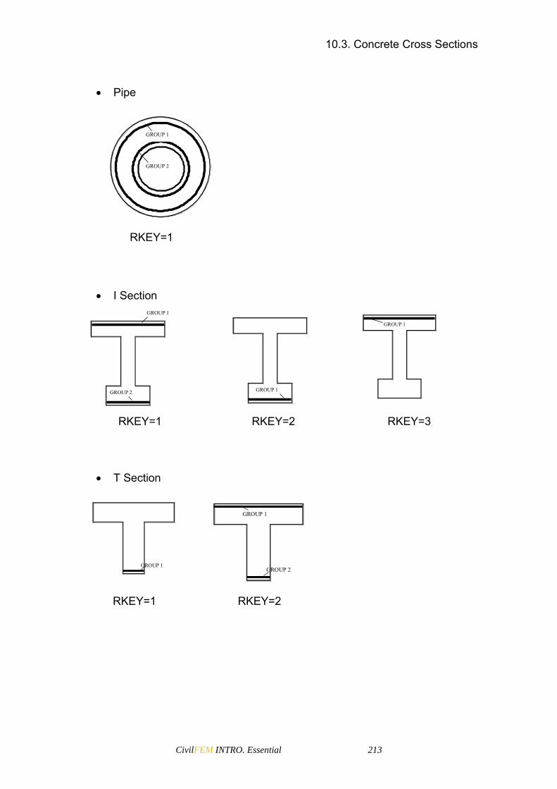
10.3. Concrete Cross Sections
CivilFEM INTRO. Essential 213
I Section
GROUP 2
GROUP 1
GROUP 1
GROUP 1
RKEY=1 RKEY=2 RKEY=3
T Section
GROUP 1
GROUP 2
GROUP 1
RKEY=1 RKEY=2
Pipe
GROUP 1
GROUP 2
RKEY=1

10.3. Concrete Cross Sections
CivilFEM INTRO. Essential 214
User defined reinforcement configuration.• For defining the bending reinforcement groups we must
specify:– Class– Location– Amount
Class– Scalable: This group may be modified (“scaled”) in the design
process.– Constant: This group is fixed and will not be scaled.
Scalable
Constant
Initial reinforcement Designed reinforcement
Location• Face that will support the reinforcement group and the
bar situation. Amount
• By ratio• By area• By bars
Class
Face
Bar situation
By area
By ratio
By bars
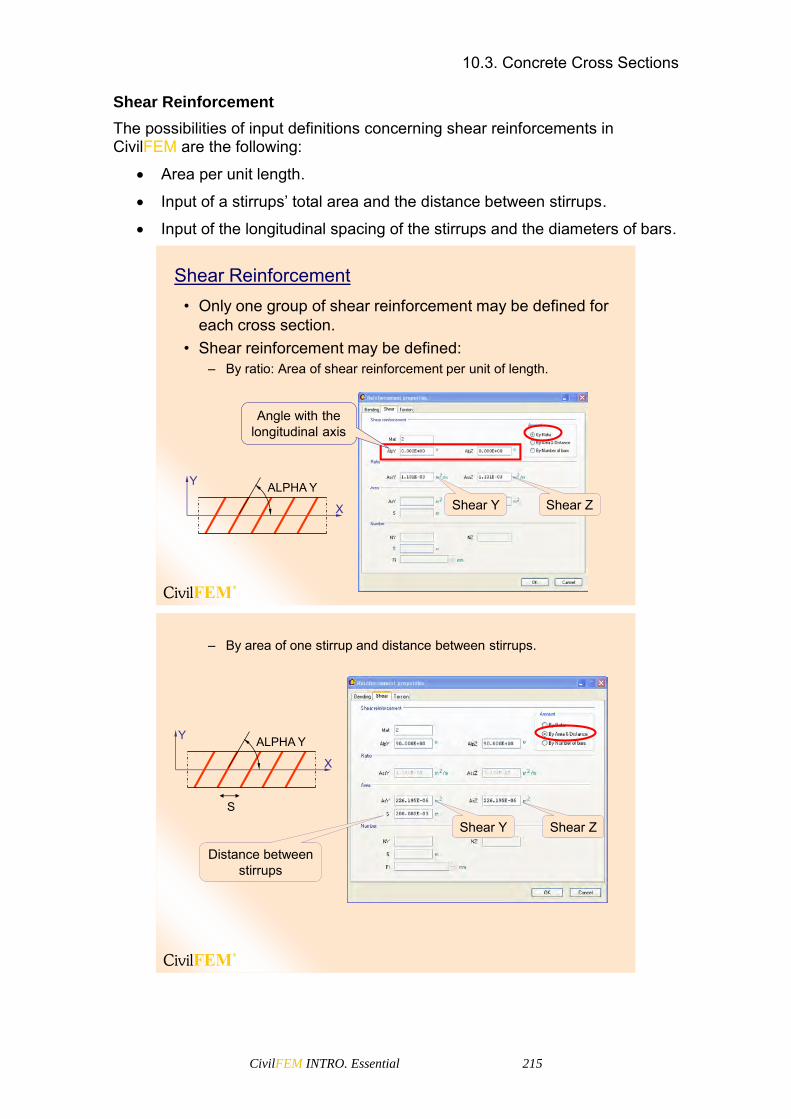
10.3. Concrete Cross Sections
CivilFEM INTRO. Essential 215
Shear Reinforcement
The possibilities of input definitions concerning shear reinforcements in CivilFEM are the following:
Area per unit length.
Input of a stirrups’ total area and the distance between stirrups.
Input of the longitudinal spacing of the stirrups and the diameters of bars.
Shear Reinforcement• Only one group of shear reinforcement may be defined for
each cross section.• Shear reinforcement may be defined:
– By ratio: Area of shear reinforcement per unit of length.
Shear Y Shear Z
Angle with the longitudinal axis
X
ALPHA YY
– By area of one stirrup and distance between stirrups.
X
ALPHA YY
S
Shear Y Shear Z
Distance between stirrups

10.3. Concrete Cross Sections
CivilFEM INTRO. Essential 216
– By number of legs and distance between stirrups.
Number of barsto Shear Y
Number of barsto Shear Z
Diameter of bars
Distance between stirrups
Z
Y
Torsion Reinforcement
Torsion Reinforcement• Only one group of torsion reinforcement may be defined for
each section.
• Torsion reinforcement has two components:– Transversal: Independent of shear reinforcement
May be defined:• By ratio• By area of stirrups and distance between stirrups• By diameter of bars and distance between stirrups
– Longitudinal: Independent of bending reinforcement May be defined:
• By total area• By number of bars and diameter
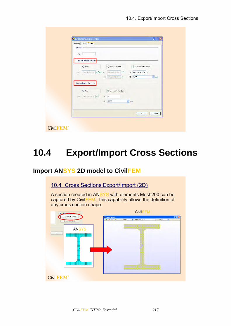
10.4. Export/Import Cross Sections
CivilFEM INTRO. Essential 217
10.4 Export/Import Cross Sections
Import ANSYS 2D model to CivilFEM
10.4 Cross Sections Export/Import (2D)
A section created in ANSYS with elements Mesh200 can be captured by CivilFEM. This capability allows the definition of any cross section shape.
ANSYS
CivilFEM
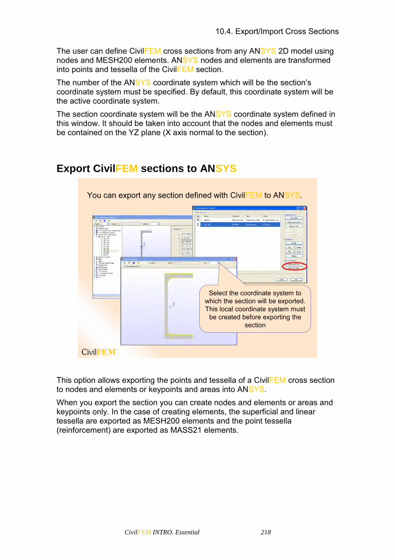
10.4. Export/Import Cross Sections
CivilFEM INTRO. Essential 218
The user can define CivilFEM cross sections from any ANSYS 2D model using nodes and MESH200 elements. ANSYS nodes and elements are transformed into points and tessella of the CivilFEM section. The number of the ANSYS coordinate system which will be the section’s coordinate system must be specified. By default, this coordinate system will be the active coordinate system. The section coordinate system will be the ANSYS coordinate system defined in this window. It should be taken into account that the nodes and elements must be contained on the YZ plane (X axis normal to the section).
Export CivilFEM sections to ANSYS
You can export any section defined with CivilFEM to ANSYS.
Select the coordinate system to which the section will be exported. This local coordinate system must
be created before exporting the section
This option allows exporting the points and tessella of a CivilFEM cross section to nodes and elements or keypoints and areas into ANSYS. When you export the section you can create nodes and elements or areas and keypoints only. In the case of creating elements, the superficial and linear tessella are exported as MESH200 elements and the point tessella (reinforcement) are exported as MASS21 elements.
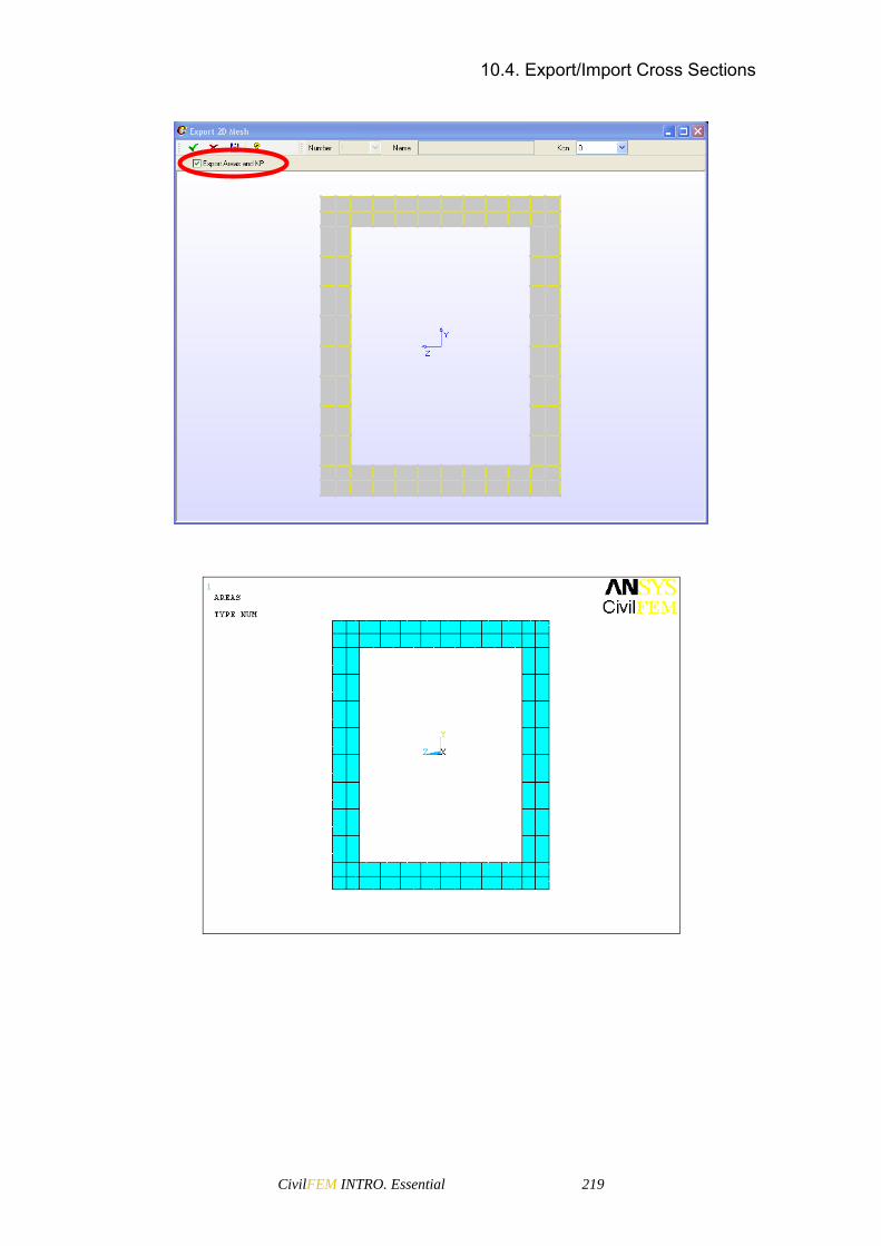
10.4. Export/Import Cross Sections
CivilFEM INTRO. Essential 219
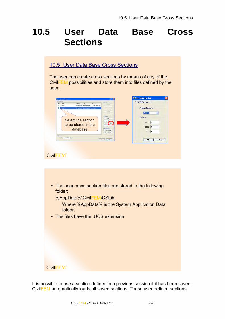
10.5. User Data Base Cross Sections
CivilFEM INTRO. Essential 220
10.5 User Data Base Cross Sections
10.5 User Data Base Cross Sections
The user can create cross sections by means of any of the CivilFEM possibilities and store them into files defined by the user.
Select the section to be stored in the
database
• The user cross section files are stored in the following folder:%AppData%\CivilFEM\CSLib
Where %AppData% is the System Application Data folder.
• The files have the .UCS extension
It is possible to use a section defined in a previous session if it has been saved. CivilFEM automatically loads all saved sections. These user defined sections

10.6. List of Cross Section
CivilFEM INTRO. Essential 221
are displayed in a tree form, showing each of the files created and the sections it contains.
The properties are read and listed in the active unit
system and codeCivilFEM automatically loads all saved sections
10.6 List of Cross Section
10.6 List of Cross Section
• The data of the defined sections can be listed in HTML or ASCII format. Choose between:
– General List (only general properties are listed)– Detailed list (we can select which properties are to be listed)
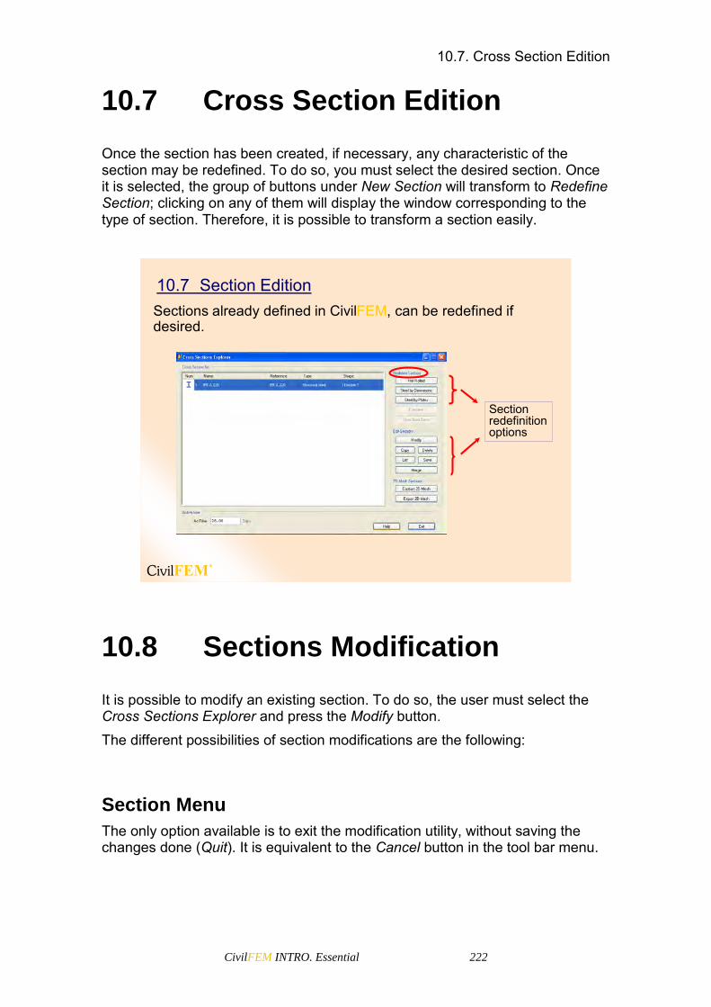
10.7. Cross Section Edition
CivilFEM INTRO. Essential 222
10.7 Cross Section Edition
Once the section has been created, if necessary, any characteristic of the section may be redefined. To do so, you must select the desired section. Once it is selected, the group of buttons under New Section will transform to Redefine Section; clicking on any of them will display the window corresponding to the type of section. Therefore, it is possible to transform a section easily.
10.7 Section EditionSections already defined in CivilFEM, can be redefined if desired.
Sectionredefinitionoptions
10.8 Sections Modification
It is possible to modify an existing section. To do so, the user must select the Cross Sections Explorer and press the Modify button. The different possibilities of section modifications are the following:
Section Menu
The only option available is to exit the modification utility, without saving the changes done (Quit). It is equivalent to the Cancel button in the tool bar menu.

10.8. Sections Modification
CivilFEM INTRO. Essential 223
Select Menu
In this menu, subgroups of the selected data can be chosen. The selection may be carried out with the mouse pointer (By Pick), by Material Type or by Material Number. If the selected option is By Pick, CivilFEM will provide a list of entities from which to choose:
Points
Tesella
Faces
Reinforcements
Plates
Edit Menu In this menu the user may access the section’s properties edition.

10.8. Sections Modification
CivilFEM INTRO. Essential 224
In this menu the user may access the section properties edition.
Common data
10.8 Cross Sections Data
• Common Data– General Properties
Data identifying the section:• Identification number, type, shape, titles…
– Dimensions Data with the dimensions and geometry of the section:
• Depth, width, thickness of the flange and web, filet radius
– Points and Tessella Structure When defining a cross section in CivilFEM the program
automatically divides it into points and tessella. Points are used for the geometric description of the cross section and tessella are needed when calculating the section’s geometric resistance.

10.8. Sections Modification
CivilFEM INTRO. Essential 225
– Points Data Data associated to each section point.
• Material number associated to the point, material type,…– Tessella Data
Data associated to each tessella such as:• Material associated to the tessella, material type,…
The Refining Tessella option (TRefine) allows the user to increment the number of tessella that form the section (remeshing the section) to obtain more precise results in the calculations carried out.
You can increase the number of cross section points and tessella in the cross section window:
– Edit > TRefine
You can change the material of the tessella:
– Edit > Tessellum
Select the tessella to be changed,pick on the change material buttonand select the number of theMaterial.

10.8. Sections Modification
CivilFEM INTRO. Essential 226
Type of Tessella:
TYPE 1
Point
Used for: Representing reinforcements defined by bars Associate LINK and BEAM elements ends (I or J)
TYPE 2
Line with two points
Used for: Represent plates Associate SHELL elements faces Represent reinforcements uniformly distributed (Fi=0)
TYPE 3
Line with three points
Used for: Associate SHELL elements faces with edge nodes Represent reinforcements distributed uniformly by curves (Fi=0)
TYPE 4
Triangle with three
points
Used for: Associate SOLID elements faces
TYPE 5
Triangle with six points
Used for: Associate SOLID element faces with edge nodes
TYPE 6
Quad with four points
Used for: Associate SOLID element faces
TYPE 7
Quad with eight points
Used for: Associate SOLID element faces with edge nodes

10.8. Sections Modification
CivilFEM INTRO. Essential 227
– Mechanical and Structural Properties Properties used for checking according to codes and for
structural analysis (they are transferred to ANSYS as real constants for the calculation of the model).
• Inertia moment, torsional moment, area, shear center, … For composite cross sections CivilFEM automatically
homogenizes these properties to the material with a lower number inside the section.
Material 1
Homogenize to Material 1
Material 2
CivilFEM allows the section properties to be changed (Edit > Mechanical Properties) just by entering the value in the corresponding edit box. The original value can be retrieved again by clicking on the A button (autocalculate).

10.8. Sections Modification
CivilFEM INTRO. Essential 228
Concrete Sections Data
• Concrete Sections Data– Code properties
Additional data for calculating shear and torsion according to codes:
• Shear width, effective depth, uniform thickness, wall equivalent width…
– Additional data for crack checking according to codes: Bars diameter, effective reinforcement ratio,…
Steel Sections Data
• Steel Sections Data– Code Properties
Possible additional cross section data needed for steel code checks:
• Areas of holes to obtain the net area, summation of the forces transmitted by the bolts…
– Plates Structure Data concerning the plates decomposition of the section:
• Number of plates, type, connections, thickness, coordinates, class, reduction factors…
The plates structure is automatically defined when creating any type of steel section.
The class and reduction factors of the section are the output data of calculations with codes (Eurocode 3, LRFD and British Standard).

10.9. Concrete Code Properties
CivilFEM INTRO. Essential 229
10.9 Concrete Code Properties
10.9 Concrete Code Properties
• Concrete code properties are additional cross section properties needed to check and design shear and torsion reinforcement and to carry out crack checking according to codes or standards.
• Each concrete code has its own code properties. These properties are automatically defined, for sections by dimensions, when defining the cross section geometry.
• It is only necessary to redefine these properties if you want to use properties other than the default values or if you are using a generic shape cross section.
• To edit Code properties, select a concrete section and press modify. Then Edit > Code Properties
(Main Menu > Civil Preprocessor > Cross section > Modify)


10.9. Concrete Code Properties
CivilFEM INTRO. Essential 231
11 Shell Vertex


11.1. Shell Vertex Concept
CivilFEM INTRO. Essential 233
11.1 Shell Vertex Concept
• A shell element concept equivalent to the beam cross section used to represent properties of a particular vertex of the shell element.
• Shell vertices contain data and properties of the shell element nodes.
Enter the thickness
Select the material
11.1 Shell Vertex Concept
Steel shell
It is also possible to Create a new vertex, Modify an existing vertex, Delete it, Create a vertex from another vertex already defined, and List created vertices. When a vertex is created or modified, a window with two sections is displayed. The first one refers to general parameters and the second one to Reinforcement.

11.2. Shell Reinforcement
CivilFEM INTRO. Essential 234
Enter the thickness
Select the material
Concrete shell
11.2 Shell Reinforcement
May be bending or/and shear reinforcement (concrete shells). Parameters for bending reinforcement:
Material: reinforcing steel.
Reinforcement cover.
Reinforcement per unit of length: Top surface in X direction Bottom surface in X direction Top surface in Y direction Bottom surface in Y direction
KRnf: Braced reinforcement bars (only for CEB method)
ALP: Reinforcement angle (only for WOOD´S method)
THETA: Angle of compressive strut

11.2. Shell Reinforcement
CivilFEM INTRO. Essential 235
11.2 Shell Reinforcement (concrete shell)• It is not necessary to define an initial amount of
reinforcement; only define the reinforcement material number (Rmat).
Material
Reinforcementper unit length
Braced reinforcement bars Angle of reinforcement
(only for Wood method)
Concrete compression strut angle
Reinforcement cover

11.2. Shell Reinforcement
CivilFEM INTRO. Essential 236
Parameters for shear reinforcement:
Material: reinforcing steel.
The reinforcement can be defined by ratio or by number of bars. Reinforcement by ratio: Ass Reinforcement by number of bars: NX, NY, SX, SY, Fi
11.3 Shear Reinforcement (concrete shell)
MaterialBy Ratio or By Number of bars
Ass: Reinforcement area per unit area SX: Longitudinal
spacing of the bars
NX or NY: Number of bars per unit length
Fi: Diameter of bars (by number of bars)

11.3. List of Shell Vertex
CivilFEM INTRO. Essential 237
11.3 List of Shell Vertex
11.4 List of Shell Vertex
The data of the defined shell vertex can be listed in HTML or ASCII format. Choose between:
– Short List – Detailed list


CivilFEM INTRO. Essential 239
12 CivilFEM Member Properties


12.1. Member Properties Concept
CivilFEM INTRO. Essential 241
12.1 Member Properties Concept
The Member Properties setting contain additional data for check and design according to codes. These data embrace properties not directly associated to the transversal cross section but to its functioning as a member of a group of elements in a model.
• Member properties are data of the structure needed to check according to codes and are not directly defined as cross sections, element properties, or geometry.
12.1 Member Properties Concept
• Member properties depend on the active code.
• CivilFEM associates member properties to Beam & Shell Properties or Solid Sections.
The properties already created are listed in the member properties window. Moreover, New Properties can be created and existing properties Deleted, Modified, Copied or Listed.

12.1. Member Properties Concept
CivilFEM INTRO. Essential 242
The following window is displayed when a member property is created or modified.
It is possible to change the property Number and Name in this window. The different code-dependent parameters may be modified in the first tabs. In the last tab, non-linearities for CivilFEM, non-linear beam calculations are activated or deactivated (Bridges and Civil Non Linearities Module).
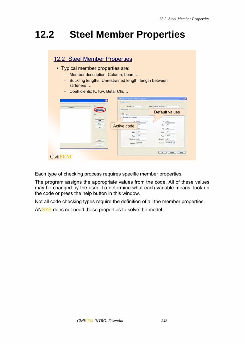
12.2. Steel Member Properties
CivilFEM INTRO. Essential 243
12.2 Steel Member Properties
12.2 Steel Member Properties• Typical member properties are:
– Member description: Column, beam,…– Buckling lengths: Unrestrained length, length between
stiffeners,…– Coefficients: K, Kw, Beta, Chi,…
Default values
Active code
Each type of checking process requires specific member properties. The program assigns the appropriate values from the code. All of these values may be changed by the user. To determine what each variable means, look up the code or press the help button in this window. Not all code checking types require the definition of all the member properties. ANSYS does not need these properties to solve the model.

12.3. Concrete Member Properties
CivilFEM INTRO. Essential 244
12.3 Concrete Member Properties
12.3 Concrete Member Properties• Typical member properties are:
– Strength reduction factor (used in certain codes such as AS3600)
Default values
Active code
The strength reduction factor is a member property that can be globally assigned to the whole structure (CivilFEM Setup), or assigned to each of the elements using Member Properties.

CivilFEM INTRO. Essential 245
13 CivilFEM Beam & Shell Properties


13.1. Beam & Shell Properties and Real Constants
CivilFEM INTRO. Essential 247
13.1 Beam & Shell Properties and Real Constants
Beam and Shell Properties contain all the properties of a beam or shell element type, not determined by their type, material, or location of nodes. Once the cross sections (for beam elements) or the shell vertex (for shell elements) are defined, the definition of the Beam and Shell Properties will associate the end of the element with the corresponding Member Property and any other properties (offsets, etc.).
• Beam & Shell properties in CivilFEM are linked to ANSYSsections and sets of real constants. The number identifying the CivilFEM beam & shell property corresponds to the real constants set number (or section number for BEAM188 BEAM189, SHELL181 and SHELL281) in ANSYS.
• When assigning a Beam & Shell property to an element, the corresponding ANSYS real constant set or section is assigned.
• When deleting a Beam & Shell property with CivilFEMcommands, the corresponding real constant set or section in ANSYS is automatically deleted.
• It is important to assign the Real Constant or Section attribute to the geometry before meshing. This attribute is the Beam & Shell Property number.
13.1 Beam & Shell properties and Real Constants
It is important to indicate during the definition of the property the element type to which the Beam and Shell Property will be associated for the correct definition of the real constants.
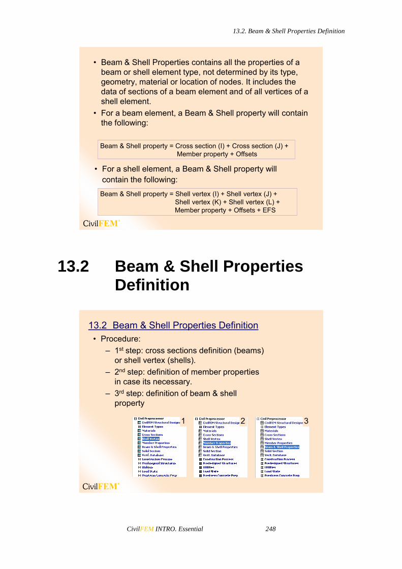
13.2. Beam & Shell Properties Definition
CivilFEM INTRO. Essential 248
• Beam & Shell Properties contains all the properties of a beam or shell element type, not determined by its type, geometry, material or location of nodes. It includes the data of sections of a beam element and of all vertices of a shell element.
• For a beam element, a Beam & Shell property will contain the following:
Beam & Shell property = Cross section (I) + Cross section (J) + Member property + Offsets
• For a shell element, a Beam & Shell property willcontain the following:
Beam & Shell property = Shell vertex (I) + Shell vertex (J) + Shell vertex (K) + Shell vertex (L) + Member property + Offsets + EFS
13.2 Beam & Shell Properties Definition
13.2 Beam & Shell Properties Definition• Procedure:
– 1st step: cross sections definition (beams) or shell vertex (shells).
– 2nd step: definition of member properties in case its necessary.
– 3rd step: definition of beam & shell property
1 2 3

13.2. Beam & Shell Properties Definition
CivilFEM INTRO. Essential 249
Beam Property
The Beam Property window is divided into: Upper Menu – The beam’s general properties are defined here: Number,
Name, Beam type (Ename) and Offset location (Offset). Cross Section (left side) – where the type of beam section is chosen and its
offsets can be seen and modified. Member Properties (right side) – where member properties of the beam are
chosen and can be reviewed. On the left side (Cross Section), it is possible to choose if the beam has a constant section or is a tapered beam (pressing on the Constant Section button will change the screen to display Variable Section)
• It is possible to define variable cross sections for both element ends by choosing an appropriate element type (BEAM44 or BEAM54).
Member properties
Cross section
List of ANSYS Real Constants
Element type
Node location (offset)
Offset definition
There is a button in the bottom side to display the Real Constants assigned to the beam.
Shell Property
The window is the same in the case of Shell Properties, but beam ends (sections) are substituted by shell ends (vertex). Instead of displaying each end, two fields with the vertex Thickness and the Material are shown. For SHELL63 elements, the Elastic Foundation Stiffness (EFS) edit box is available.

13.2. Beam & Shell Properties Definition
CivilFEM INTRO. Essential 250
• It is possible to define variable Shell sections by choosing an appropriate element type.
Shell vertex
List of ANSYS real constants
Element type
Elastic Foundation Stiffness (Shell 63)
Member properties
Offset (Shell 181 and 281)
Elastic foundation stiffness is only available for SHELL63 elements.
Node location (offsets)
Offset Definition
When creating a BEAM44 or BEAM54 The nodes location can be modified by entering an offset.
(~BMSHOFF command).
Offset definition
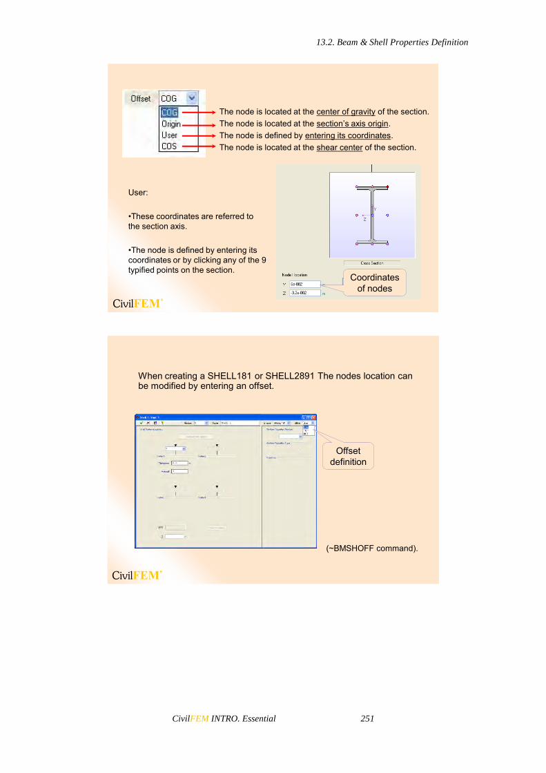
13.2. Beam & Shell Properties Definition
CivilFEM INTRO. Essential 251
The node is located at the center of gravity of the section.The node is located at the section’s axis origin.The node is defined by entering its coordinates.The node is located at the shear center of the section.
User:
•These coordinates are referred to the section axis.
•The node is defined by entering its coordinates or by clicking any of the 9 typified points on the section.
Coordinates of nodes
When creating a SHELL181 or SHELL2891 The nodes location can be modified by entering an offset.
(~BMSHOFF command).
Offset definition

13.3. Beam 188 and 189 elements
CivilFEM INTRO. Essential 252
The node is located at the any height.The node is located at the Top of the shell.The node is located at the Bottom of the shell.
User:
•These coordinates refer to center of the shell element.
•The node is defined by entering the vertical coordinate.
Coordinate of node
13.3 Beam 188 and 189 elements
ANSYS 10.0
NOV 29 2005
12:31:27
NODAL SOLUTION
STEP=1
SUB =1
TIME=1
SX (AVG)
RSYS=0
PowerGraphics
EFACET=1
AVRES=Mat
DMX =.003277
SMN =-.146E+08
SMX =.146E+08
1
MN
MX
X
Y
Z
-.146E+08
-.113E+08
-.809E+07
-.486E+07
-.162E+07
.162E+07
.486E+07
.809E+07
.113E+08
.146E+08
13.3 Beam 188 and 189 elements
• Beam 188 and 189 elements allow to render the real shape of the section on the beam model:
PlotCtrls > Style > Size and Shape …
• This allows the user to plot results (such as stresses) on the 3D shape of the element, not only on the directrix of the beam.
Display of element real
shape

CivilFEM INTRO. Essential 253
14 CivilFEM Solid Models Analysis


14.1. Solid Section Concept
CivilFEM INTRO. Essential 255
14.1 Solid Section Concept
Sections associated to elements of 2D and 3D models of finite elements.It is used to extend the checking capabilities of the program to generic models in 2D/3D with elements LINK, BEAM, SHELL, PLANE and SOLID.
14.1 Solid Section Concept
CivilFEM allows the definition of solid sections from a 2D model containing the following two-dimensional elements: LINK1, PLANE2, BEAM3, PLANE42, BEAM54, PLANE82, PLANE182, PLANE183. CivilFEM allows the definition of solid sections from a 3D model containing the following three-dimensional elements: BEAM4, LINK8, LINK10, PIPE16, PIPE20, BEAM23, BEAM24, SHELL41, SHELL43, BEAM44, SOLID45, SHELL63, SOLID64, SOLID65, SOLID72, SOLID73, SOLID92, SHELL93, SOLID95, SHELL143, LINK180, SHELL181, SOLID185, SOLID186, SOLID187, BEAM188, BEAM189.
14.2 Capturing Solid Sections
To define a solid section from a 2D or 3D model, it is necessary to select the plane of nodes that defines the section situation and the elements that provide their characteristics to the section. The definition of a solid section implies the automatic definition of the associated cross section. This cross section will be created by points, associated with the selected nodes of the model, and by tessella, corresponding with the selected elements of the model that share
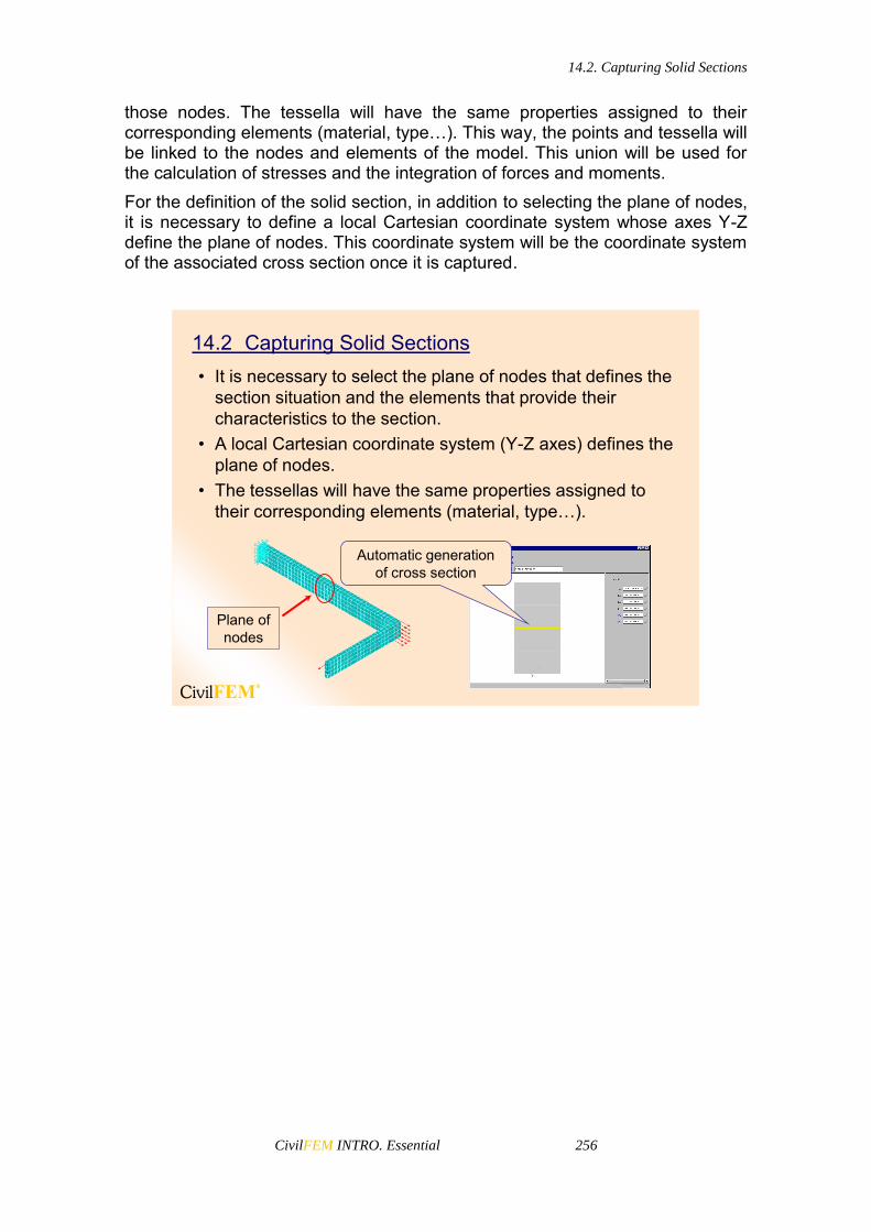
14.2. Capturing Solid Sections
CivilFEM INTRO. Essential 256
those nodes. The tessella will have the same properties assigned to their corresponding elements (material, type…). This way, the points and tessella will be linked to the nodes and elements of the model. This union will be used for the calculation of stresses and the integration of forces and moments. For the definition of the solid section, in addition to selecting the plane of nodes, it is necessary to define a local Cartesian coordinate system whose axes Y-Z define the plane of nodes. This coordinate system will be the coordinate system of the associated cross section once it is captured.
14.2 Capturing Solid Sections• It is necessary to select the plane of nodes that defines the
section situation and the elements that provide their characteristics to the section.
• A local Cartesian coordinate system (Y-Z axes) defines the plane of nodes.
• The tessellas will have the same properties assigned to their corresponding elements (material, type…).
Plane of nodes
Automatic generationof cross section

CivilFEM INTRO. Essential 257
15 Load Combinations


15.1. Typical Problems
CivilFEM INTRO. Essential 259
15.1 Typical Problems
CivilFEM provides, through the combinations module, the possibility of operating with a results set and combining them in such a way that given targets can be achieved. Therefore, the results combination is based on the search of the combination among a certain data set that, following certain rules, fulfills the given targets at each node of the structure. Listed below are some of the questions that CivilFEM’s load combination module can solve.
Problem example 1: Loads in building• What is the maximum moment in section A-A?• Where should the variable load be located?• Should the wind blow from right to left or from left to right?• Is the dead load favorable or unfavorable?
A A
???
?
?
?
15.1 Typical Problems

15.1. Typical Problems
CivilFEM INTRO. Essential 260
Problem example 2: Mobile loads• Where should the two engines be located for the stress to
be maximum at point P?
P
? ? ?
Problem example 3: Selecting coefficients
G, Gravity k, Gravity G, Dead k, Dead Q, Live k, Live
Q, Wind 0, Wind k, Wind Q,Thermal 0, Thermal k, Thermal
E γ G γ G γ Q
γ ψ Q γ ψ Q ...
gG = 1.00 or 1.35 ?
gQ = 1.00 or 0.00 ?
Scheme of combinations in Eurocodes
You must decide independently for each section of the structure.

15.2. Main Applications of CivilFEM Combinations
CivilFEM INTRO. Essential 261
15.2 Main Applications of CivilFEM Combinations
15.2 Main Applications of CivilFEM Combinations
• Mobile loads• Combinations with variable coefficients (favorable/
unfavorable)• Actions in different directions (wind, earthquakes, …)• Combinations according to codes logic
Example:
2x300kN located in the most unfavorable position
2x200kN located in the most unfavorable position
Virtual lane 1
Virtual lane 2
Border
Border
Border
Target:•Maximum MZ•Minimum MZ
Permanent actions (Gk)Self weight Dead load of 20 kN/m
Road traffic actions (Qk)Vehicles (Double-axis)
2x300 kN in virtual lane 12x200 kN in virtual lane 2
Uniformly distributed loads 9.0 kN/m2 in virtual lane 12.5 kN/m2 in virtual lane 22.5 kN/m2 in the other areas

15.2. Main Applications of CivilFEM Combinations
CivilFEM INTRO. Essential 262
Eurocode 1: Permanent and transient situations (simplified)
kQkG QG
Safety factor
for variable actions:
Q = 0 if it is favorable
Q = 1.00 if it is unfavorable
Safety factor
for permanent actions:
G = 1.00 if it is favorable
G = 1.35 if it is unfavorable
Permanent actions Variable actionsThe program will select the coefficients to apply for each target and element.
1st level combinations2nd level combinations3rd level combinations
file.RST
• Load state 1
“Self weight”• Load state 2
“Dead load”• Load states 3 to 21
“Vehicle 1”• Load states 22 to 40
“Vehicle 2”• Load states 41 to 58
“Uniformly distributed load”
file.CMB or file.CVMB
• Combination 1
“Permanent actions”
• Combination 5
“Road traffic actions”
• Combination 2
“Vehicle in virtual lane 1”• Combination 3
“Vehicle in virtual lane 2”• Combination 4
“Uniformly distributed loads”
• Combination 6
“Permanent and transient situations”
Start State Combined results

15.3. General Procedure I. Obtain All possible Load Cases
CivilFEM INTRO. Essential 263
15.3 General Procedure I. Obtain All possible Load Cases
With CivilFEM Combination module you can define certain combination rules and obtain all the possible load cases that can be generated following those rules.
15.3 General Procedure I• Define combination rules
– Start States of each combination– Combination type– Coefficients for each start state
• Calculate– Obtain all the possible load cases
• Results are appended in the results file (from the last load step defined).
This procedure will create new load steps that will be appended after the last step is defined in the RST and RCV files. Postprocessing of new load steps is done in the same way as for solved load steps.

15.4. General Procedure II. Combine Results of the Whole Structure by Searching for Specific Targets
CivilFEM INTRO. Essential 264
15.4 General Procedure II. Combine Results of the Whole Structure by Searching for Specific Targets
It is also possible to combine the initial load states following certain combination rules by looking for a specific target (or a group of targets) instead of combining all of the results. This will provide an envelope of results for the whole structure. For example, combining for the maximum shear force will create an envelope of maximum shear forces that can be produced for all the possible combinations throughout the structure. Apart from obtaining the enveloped results, CivilFEM will also provide the concomitant results inside the same group. This is to say, these results occur at the same time as the target is obtained. For example, for a beam element structure for which the maximum shear force is the desired target, CivilFEM will also provide the axial force or the bending moments that happen at the same time (for the same combination) as the maximum shear force (the load combination will be different for each point of the structure).
15.4 General Procedure II• Define combination rules
– Start States of each combination– Combination type– Coefficients for each start state
• Define Targets• Calculate
– Obtain envelopes searching for the targets• Point to combined results (new CMB and CVMB files)• Read combined results
This procedure is very useful when the load combinations may generate many load cases (moving vehicle, for example).

15.5. General Procedure III. Search for a Specific Result at a Specific Location
CivilFEM INTRO. Essential 265
15.5 General Procedure III. Search for a Specific Result at a Specific Location
Sometimes it may be useful to obtain a specific result at a specific location or entity (beam, node, cross section, solid section, etc.). An example would be obtaining the maximum vertical displacement at the center of a span. In this case, the definition of the combination rules is needed; however, instead of combining all the results, an inquiry will be done for a certain target at a specified location.
15.5 General Procedure III• Define combination rules
– Start States of each combination– Combination type– Coefficients for each start state
• Define Targets• Inquire
– Worst hypotheses and coefficients– Results for certain points– Global Concomitance– Concomitant loads– Results at one entity (node, element, section, etc.). Not for the
whole model.

15.6. Define Combination Rules
CivilFEM INTRO. Essential 266
15.6 Define Combination Rules
Start States
15.6 Defining Combination Rules
• Each combination has its own start states• The start states can be obtained from:
– Jobname.RST or Jobname.RCV– Combinations of CivilFEM (nested combinations)
• From jobname.RST or jobname.RCV a start state can be identified by:
– The Load Step and Substep– The number of Data Set
• From CivilFEM combinations, a start state can be identified by:
– The combination number
Start States
Combination Rules
Combination Rules• Combination Rules are logic relations between Start
States.• Each combination rule has its own Start States.• A combination rule may have any number of Start States
(up to a maximum of 1,000,000).• The result of the combination is called the combined result.• Combination rules can be nested unlimited times.
– That means that the combined result of the combination i can be a start state for the combinations i+1, i+2, …, n, and combined results of combination i+1 may be a start state for combinations i+2, i+3, …, n
...Q ψ γQ γG γG γ E Windk, Wind0, WindQ,Live k,Live Q,Dead k,Dead G,Gravity k,Gravity G,
Combination RuleCombined result Start State

15.6. Define Combination Rules
CivilFEM INTRO. Essential 267
• There are 8 Types of Combination Rules– Addition [ADD]– Addition with Variable Coefficients [ADDVC]– Incompatible or Exclusive Start States [INCOMPAT]– Compatible Start States [COMPATIB]– Start States Option [OPTION]– Opposed Start States [OPPOSED]– Selection [SELEC]– Selection with variable coefficients [SELECVC]
Addition [ADD]• Description
– Addition of all the Start States multiplied by fixed coefficients
• Required Coefficients– 1 Coefficient per Start State
• Additional Data– None
• Notes– It is the classic addition– It is equivalent to ANSYS combinations

15.6. Define Combination Rules
CivilFEM INTRO. Essential 268
Addition with Variable Coefficients [ADDVC]
• Description– Addition of all the Start States multiplied by variable coefficients
• Required Coefficients– 2 Coefficients per Start State
• Additional Data– None
• Notes– It can be used in code combinations
For example C = fg.G + fq.Q
Incompatible or Exclusive Start States [INCOMPAT]
• Description– As maximum one Start State may be selected (one or none) from
the defined ones
• Required Coefficients– None
• Additional Data– None
• Notes– Used for representing mobile loads which can only occupy one
position of the possible ones

15.6. Define Combination Rules
CivilFEM INTRO. Essential 269
Compatible Start States [COMPATIB]
• Description– Addition of any subset of the Start States defined (none, one,
several or all of them)
• Required Coefficients– None
• Additional Data– None
• Notes– For representing mobile loads which may occur simultaneously
(surface loads)
Option [OPTION]
• Description– Only one Start State is selected from the ones defined
• Required Coefficients– None
• Additional Data– None
• Notes– For selecting from several hypotheses. For example, different
code hypotheses...

15.6. Define Combination Rules
CivilFEM INTRO. Essential 270
Opposed Start States [OPPOSED]
• Description– Addition of all the Start States, but with each one multiplied by
+1.00 or -1.00
• Required Coefficients– None
• Additional Data– None
• Notes– For actions which may act indistinctly in two opposed directions
(earthquake, wind...)
Selection [SELECT]
• Description– Addition of a fixed number of Start States selected from the ones
defined
• Required Coefficients– None
• Additional Data– Number of Start States to add
• Notes– For mobile loads which can act simultaneously in more than one
position

15.6. Define Combination Rules
CivilFEM INTRO. Essential 271
Selection with variable coefficients [SELECVC]
• Description– Addition of a fixed number of Start States; each can be
multiplied by two coefficients
• Required Coefficients– 2 Coefficients per Start State
• Additional Data– Number of Start States to add
• Notes– It is the most general type; by degeneration, it is adapted to
any of the previous types
Start State1
Start State
2
Start State3
Start State4
Start State5
Combination Rule
Start States selected
Selection with variable coefficients [SELECVC]• In a SELECVC combination the program adds a subgroup
selected from the start states defined for the combination rule and it multiplies each by a different coefficient. The program selects which ones are to be added for each target and for each point of the structure
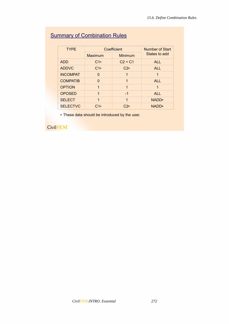
15.6. Define Combination Rules
CivilFEM INTRO. Essential 272
Summary of Combination Rules
TYPE Coefficient Number of Start States to addMaximum Minimum
ADD C1 C2 = C1 ALLADDVC C1 C2 ALLINCOMPAT 0 1 1COMPATIB 0 1 ALLOPTION 1 1 1OPOSED 1 -1 ALLSELECT 1 1 NADDSELECTVC C1 C2 NADD
These data should be introduced by the user.

15.7. Combination window
CivilFEM INTRO. Essential 273
15.7 Combination window
Once the combinations module has been initialized, any combination can be defined with of all its start states through this window:
Tool bar
Default coefficients that will be assigned to the new start state
Information and coefficients of the selected start state
Information about the selected combination or new combination
Start states list. It includes the defined combinations, the available load steps and sub steps and all the defined datasets.
Combinations and families tree Visualization modes
of the start state list
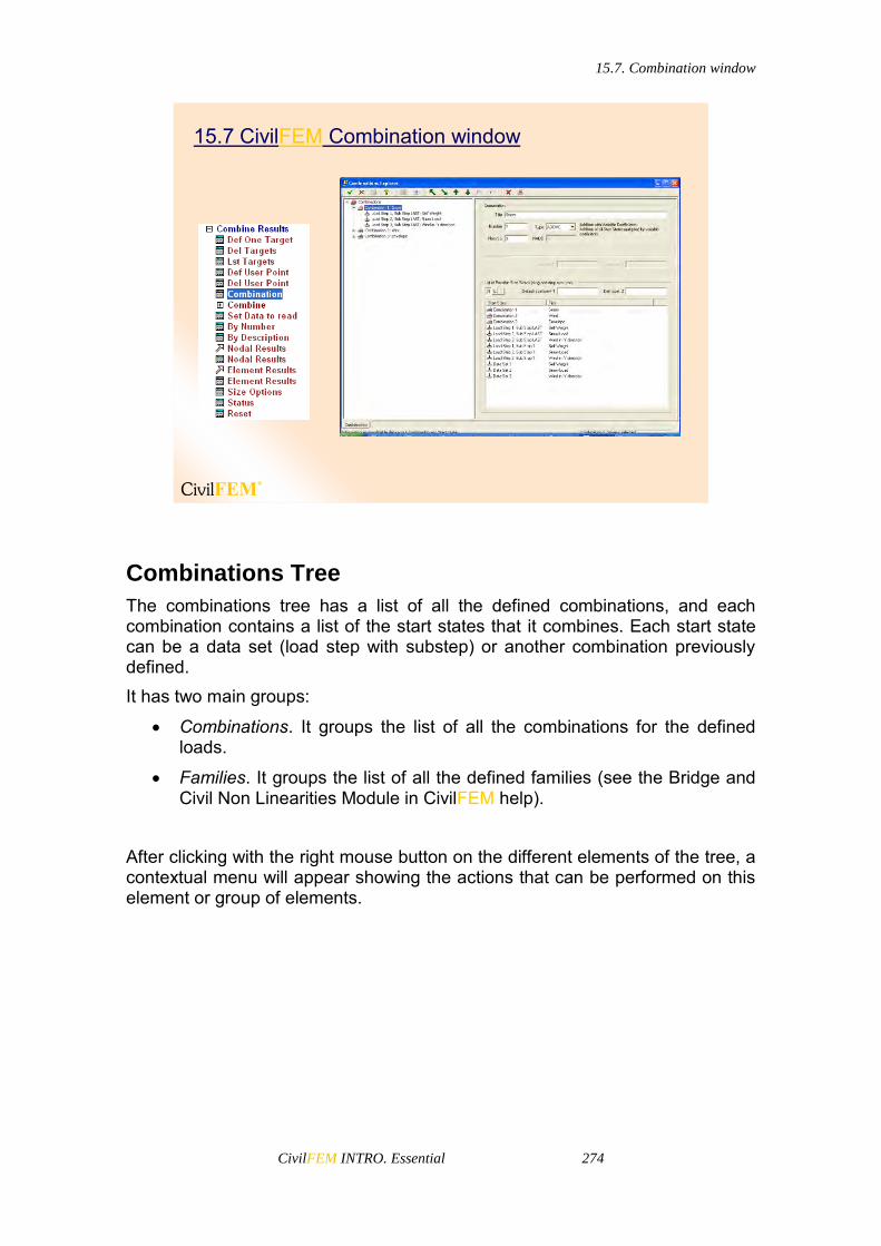
15.7. Combination window
CivilFEM INTRO. Essential 274
15.7 CivilFEM Combination window
Combinations Tree
The combinations tree has a list of all the defined combinations, and each combination contains a list of the start states that it combines. Each start state can be a data set (load step with substep) or another combination previously defined. It has two main groups:
Combinations. It groups the list of all the combinations for the defined loads.
Families. It groups the list of all the defined families (see the Bridge and Civil Non Linearities Module in CivilFEM help).
After clicking with the right mouse button on the different elements of the tree, a contextual menu will appear showing the actions that can be performed on this element or group of elements.

15.7. Combination window
CivilFEM INTRO. Essential 275
Tool Bar
Tool Bar
• The tool bar is located at the upper part of the window. The tool bar has two parts: the fixed part, that remains unchanged at any time, and the variable part, that adapts to each situation, showing only the buttons that can be used at each moment.
Information Window
This window, located at the right of the objects tree, has the following functions:
To show the properties of each selected object. Whenever an object is selected (combination, load step, dataset, family, etc.), the window will show all its properties.
To allow modification to the data.

15.7. Combination window
CivilFEM INTRO. Essential 276
To serve as a dialog box with certain actions. In some cases, for example creating a new combination, it is necessary to enter a series of values or properties to perform the desired action.
To create a new combination, it is necessary to define the type of combination and the number of start states:
Defining Combination Rules• Define the type of combination and the number of Start
States– Before starting with calculations, you must define all the
combination rules and targets.
Combination number
Combination name
Type of combinationNumber of Start States included in this combination rule
Start States List
This is a list of possible start states to choose from for a combination. The combinations previously defined can also be start states for a new combination (nested combinations).
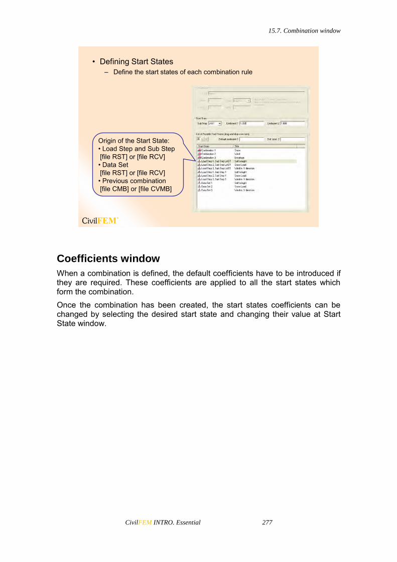
15.7. Combination window
CivilFEM INTRO. Essential 277
• Defining Start States– Define the start states of each combination rule
Origin of the Start State:• Load Step and Sub Step[file RST] or [file RCV] • Data Set[file RST] or [file RCV] • Previous combination[file CMB] or [file CVMB]
Coefficients window
When a combination is defined, the default coefficients have to be introduced if they are required. These coefficients are applied to all the start states which form the combination. Once the combination has been created, the start states coefficients can be changed by selecting the desired start state and changing their value at Start State window.
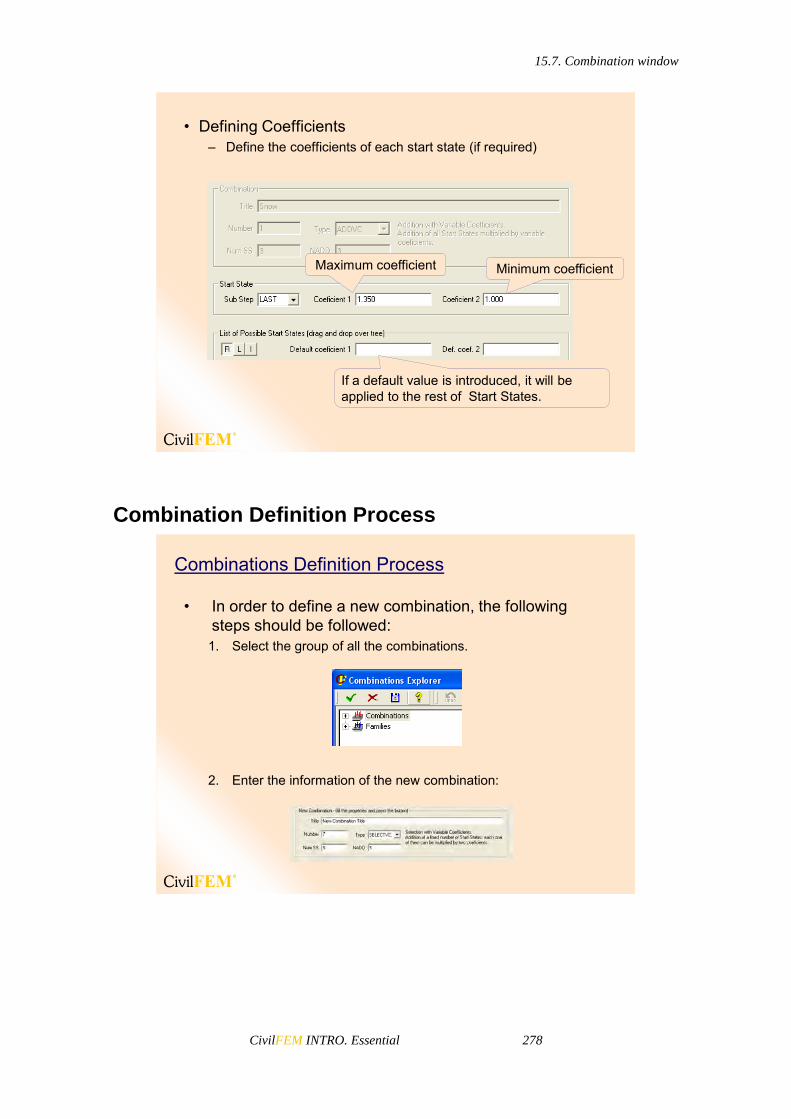
15.7. Combination window
CivilFEM INTRO. Essential 278
• Defining Coefficients– Define the coefficients of each start state (if required)
Maximum coefficient Minimum coefficient
If a default value is introduced, it will be applied to the rest of Start States.
Combination Definition Process
Combinations Definition Process
• In order to define a new combination, the following steps should be followed:1. Select the group of all the combinations.
2. Enter the information of the new combination:
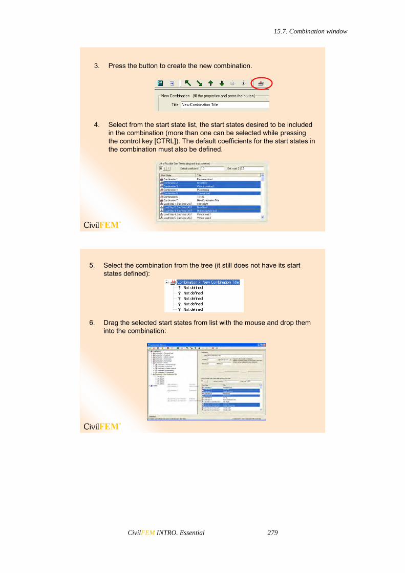
15.7. Combination window
CivilFEM INTRO. Essential 279
3. Press the button to create the new combination.
4. Select from the start state list, the start states desired to be included in the combination (more than one can be selected while pressing the control key [CTRL]). The default coefficients for the start states in the combination must also be defined.
5. Select the combination from the tree (it still does not have its start states defined):
6. Drag the selected start states from list with the mouse and drop them into the combination:

15.8. Obtain All Possible Load Cases
CivilFEM INTRO. Essential 280
6. Another possibility (instead of “drag & drop”) is to press the contextual button in the tool bar.
This way, the combination can also be completely defined:
15.8 Obtain All Possible Load Cases
15.8 Obtain All Possible Load Cases• Following the General Procedure I, you can obtain ALL the
load cases that the combinations define.• Caution: This may generate many load cases.
15.9. Defining Targets
CivilFEM INTRO. Essential 281
Following Procedure I, CivilFEM will generate all the load cases defined by the combination rules. These new load cases will be appended to the RST and RCV files, following the previously solved load steps.
15.9 Defining Targets
15.9 Defining Targets• Targets are results that have to be maximized or
minimized.• Strains, stresses, forces, moments, displacements or
reactions are TARGETS.• TARGETS may be maximum, minimum or maximum in
absolute value.• You can define as many targets as you wish; each one will
generate its own results for each combination.• The calculation of all of the combinations can be a long
process, so it is important to define all the targets before doing the combinations.
• To define targets use: Main Menu > Civil Postprocessor > Combine Results > Def One Target

15.9. Defining Targets
CivilFEM INTRO. Essential 282
• Targets are divided into ANSYS and CivilFEM targets:– Targets related to elements (ANSYS)
Beam elements Shell elements Solid elements Axisymmetric elements
– Targets related to nodes (ANSYS) Movements Reactions
– Targets related to element ends (CivilFEM) Cross sections Shell vertex CivilFEM Targets
ANSYS Targets
• Cross Section (CROSS)– CivilFEM targets include forces, moments and stresses and
strains at the section’s points calculated by CivilFEM for beam elements and stored in the CivilFEM results file (jobname.RCV).
– For cross sections, the number of points varies and may grow indefinitely, so the targets for these points are limited to 14. Therefore, the number of available targets is 6 relative to forces and moments, 14 to stresses, and 14 to strains. In the last two cases, the target refers to a point and a component of the stress or strain in that point, both defined by the user.
– Concomitance is established for all the data which compose the forces and moments in the section and for all of the components of the stresses and strains of all the points in the section.
• Shell Vertex (VERTX)– CivilFEM targets include forces, moments, and stresses and
strains calculated by CivilFEM for shell elements vertices and stored in the CivilFEM results file.
A target is defined by its referred datum (for example FX) and by its TYPE (Minimum, Maximum or Maximum in absolute value).

15.9. Defining Targets
CivilFEM INTRO. Essential 283
• Defining One Target– All the combinations defined use all the Targets defined
Target Number
Target’s Group
Type of Target
If you select CROSS as a target group, you can define the cross section points as either a stress or strain target.
Cross section point number
Stress or strain
User Point number

15.10. Combine Searching for Targets
CivilFEM INTRO. Essential 284
15.10 Combine Searching for Targets
Following Procedure II, it is possible to obtain an envelope of certain results and the concomitant results associated to these envelopes.
15.10 Combine Searching for Targets– All the combination rules simultaneously search for the targets
List of all the targets, combination rules, start states and coefficients
CivilFEM will create two additional results files: .CMB and .CVMB in which the enveloped results will be stored.
15.11 Point to Combined Results
After combining targets, it is necessary to point to the correct results file for postprocessing:
.RST/.RCV for the initial load steps.
.CMB/.CVMB for the enveloped or combined results.

15.11. Point to Combined Results
CivilFEM INTRO. Essential 285
15.11 Point to Combined Results
You can read the Original and the Combined results
Command ~CMBDAT allows the user to select or to point to original or combined results. Afterwards, the user may use ~CMB or ~CFSET commands to recall to memory the combination and target that will be postprocessed.
*.RST
Combined Results
*.RCV
*.CMB
*.CVMB
~COMBINE
~CMBDAT
1 2
Original Results
*.RCV
15.11. Point to Combined Results
CivilFEM INTRO. Essential 286
• The combined results are written in file. CMB or file. CVMB depending on the origin of the results being combined.
• File.CMB will contain combinations from file.RST. Therefore, since these combinations come from ANSYSresults file, code checking or reinforced design are not allowed.
• File.CVMB will contain combinations from file.RCV. Therefore, since these combinations come from CivilFEMresults file, code checking or reinforced design are allowed.
• If the user requires CivilFEM code checking and design capabilities for a particular combination, a CivilFEM Target (CROSS or VERTX) should be defined.
• Each combination result occupies a Load Step in file.CMB or file.CVMB.
• Therefore, you will have as many Load Steps as combination rules defined.
• The results corresponding to each target are written as a Sub Step of each Load Step. Therefore, combinations correspond to Load Steps and Targets correspond to Sub Steps.
– You will have as many Sub Steps as targets defined– All the Load Steps of file.CMB have the same amount of Sub
Steps
The results in the combined results files (.CMB/.CVMB) can be postprocessed in the same way as solved results (plot and list results, code checking, etc.)
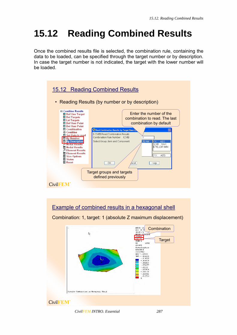
15.12. Reading Combined Results
CivilFEM INTRO. Essential 287
15.12 Reading Combined Results
Once the combined results file is selected, the combination rule, containing the data to be loaded, can be specified through the target number or by description. In case the target number is not indicated, the target with the lower number will be loaded.
15.12 Reading Combined Results
• Reading Results (by number or by description)
Enter the number of the combination to read. The last
combination by default
Target groups and targets defined previously
Example of combined results in a hexagonal shell
Combination: 1, target: 1 (absolute Z maximum displacement)
Combination
Target
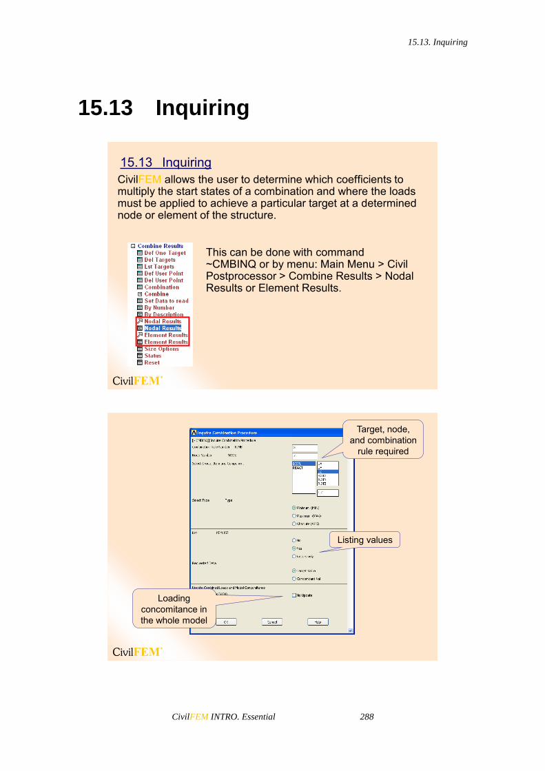
15.13. Inquiring
CivilFEM INTRO. Essential 288
15.13 Inquiring
15.13 InquiringCivilFEM allows the user to determine which coefficients to multiply the start states of a combination and where the loads must be applied to achieve a particular target at a determined node or element of the structure.
This can be done with command ~CMBINQ or by menu: Main Menu > Civil Postprocessor > Combine Results > Nodal Results or Element Results.
Target, node, and combination
rule required
Listing values
Loading concomitance in the whole model
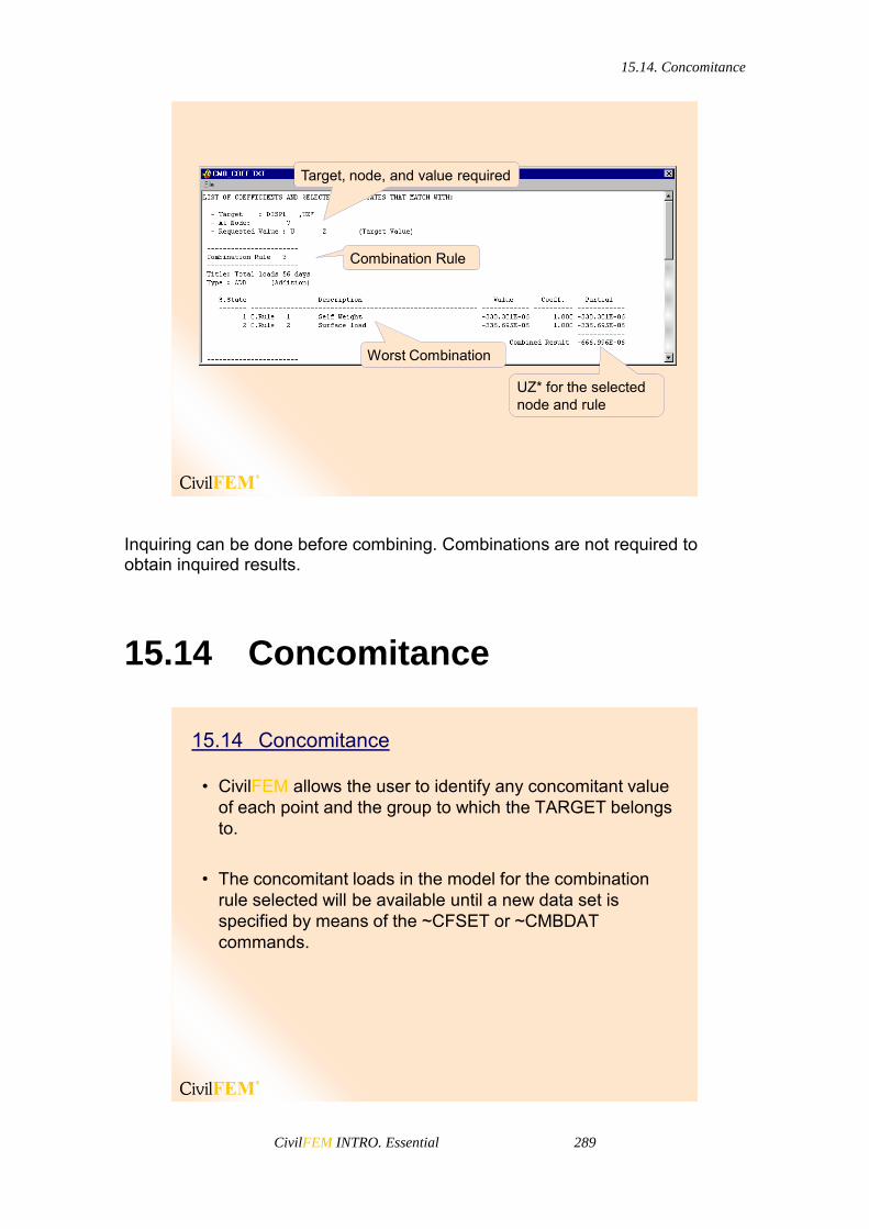
15.14. Concomitance
CivilFEM INTRO. Essential 289
Target, node, and value required
Combination Rule
Worst Combination
UZ* for the selected node and rule
Inquiring can be done before combining. Combinations are not required to obtain inquired results.
15.14 Concomitance
15.14 Concomitance
• CivilFEM allows the user to identify any concomitant value of each point and the group to which the TARGET belongs to.
• The concomitant loads in the model for the combination rule selected will be available until a new data set is specified by means of the ~CFSET or ~CMBDAT commands.


CivilFEM INTRO. Essential 291
16 Concrete Check and Design


16.1. General Concepts
CivilFEM INTRO. Essential 293
16.1 General Concepts
Checking and reinforcement design of reinforced concrete beams in CivilFEM includes structures made of 2D and 3D beam elements under axial loading plus biaxial bending, shear, torsion, and combined shear and torsion (depending on the Code or Standard). The check and design process of reinforced concrete beams under axial loading plus biaxial bending is based on the 3D interaction diagram of the cross section to be analyzed. The 3D interaction diagram contains the (FX, MY, MZ) forces and moments corresponding to the section’s ultimate strength states. Using the diagram, the program is able to check and design the section taking into account the previously obtained forces and moments acting on the section. This process allows the consideration of any generic section and the check and design of sections consisting of different concretes and reinforcement steels.
Reinforcements can be checked or designed according to the Ultimate Limit State with the CivilFEMutilities for concrete checking.
• Codes– Eurocode 2– ACI 318– ACI 349 (CivilFEM NPP)– ACI 359 (CivilFEM NPP)– CEB-FIP– Spanish code EHE– British Standard 8110– Australian code AS3600– Chinese code GB50010– Brazilian code NBR6118– AASHTO Standard
Specifications for Highway Bridges
– Indian code IS456– Russian code SP 52-101-03– Structural Design Code for
Buildings (CivilFEM NPP)
16.1 General Concepts

16.1. General Concepts
CivilFEM INTRO. Essential 294
• Code check– CivilFEM checks the structure with
a fixed amount of reinforcement and shows the safety factor of each element.
• Code design– CivilFEM checks the structure and
multiplies the initial scalable reinforcement until obtaining a safety factor (1/criterion) as close as possible to 1.00.
Code check has the following options available for beam elements and solid sections:
2D Axial force + Bending Moment. CivilFEM uses the interaction diagram of each section, taking into account the design stress-strain curve for each of the materials of the section. The moment of the Y or Z section is considered.
3D Axial force + Bending Moment. CivilFEM uses the interaction diagram of each section, taking into account the design stress-strain curve for each of the materials of the section. Moments in two directions are applied to the section.
Shear, Torsion, and combined Shear & Torsion. Availability of these three checks depends on the code formulation.
Cracking. If available, CivilFEM can obtain the cracking criterion according to code. A decompression analysis can also be made to analyze the state of the concrete structure.
For shell elements, the following options are available:
Check under bending moments and in plane loading, using the CEB-FIP formulation.
Check for bending moments, axial loads, in plane shear loads, out of plane shear loads, and torsional moments using the Orthogonal Directions Method.
16.1. General Concepts
CivilFEM INTRO. Essential 295
Check for bending moments, axial loads, in plane shear loads, out of plane shear loads and torsional moments using the Most Unfavorable Directions method.
Check the shear reinforcement (not available for all codes).
CivilFEM can obtain the needed reinforcement (design) in order to fulfill the code requirements. For beam elements, the following design options are available:
2D Axial force + Bending Moment. CivilFEM uses the interaction diagram of each section, taking into account the design stress-strain curve for each of the materials of the section. The moment of the Y or Z section is considered. Scalable reinforcement will be increased/decreased until the section reaches a safety factor of 1.0, according to the code.
3D Axial force + Bending Moment. CivilFEM uses the interaction diagram of each section, taking into account the design stress-strain curve for each of the materials of the section. Moments in two directions are applied to the section. Scalable reinforcement will be increased/decreased until the section reaches a safety factor of 1.0 according to the code.
Shear, Torsion and combined Shear & Torsion. Availability of these three checks depends on the code formulation. Shear and torsional reinforcement will be increased/decreased until the section reaches a safety factor of 1.0 according to the code.
For shell elements, the following options are available:
Design under bending moments, using the Wood-Armer formulation.
Design under bending moments and in plane loading, using the CEB-FIP formulation.
Design for bending moments, axial loads, in plane shear loads, out of plane shear loads and torsional moments using the Orthogonal Directions Method.
Design for bending moments, axial loads, in plane shear loads, out of plane shear loads and torsional moments using the Most Unfavorable Directions method.
Design the shear reinforcement (not available for all codes).

16.2. 2D Axial + Bending Check
CivilFEM INTRO. Essential 296
Results
• The available results of a concrete check or design are grouped into two blocks:
– Beam Results This group includes the results for
beam cross sections as well as the results of check or design of a solid section.
The available results to be plotted or listed depend on the type of checking or design that has been carried out.
– Shell Results This group includes the results for shell
element vertices.
16.2 2D Axial + Bending Check
16.2 2D AXIAL+BENDING CHECK
CivilFEM checks the structure with the initial reinforcement amount.
Stresses can be limited for concrete or for the reinforcement
This check only complies with the section’s strength requirements, thus ignoring the requirements related to the minimum reinforcement amounts or dispositions for each code and structural typology.
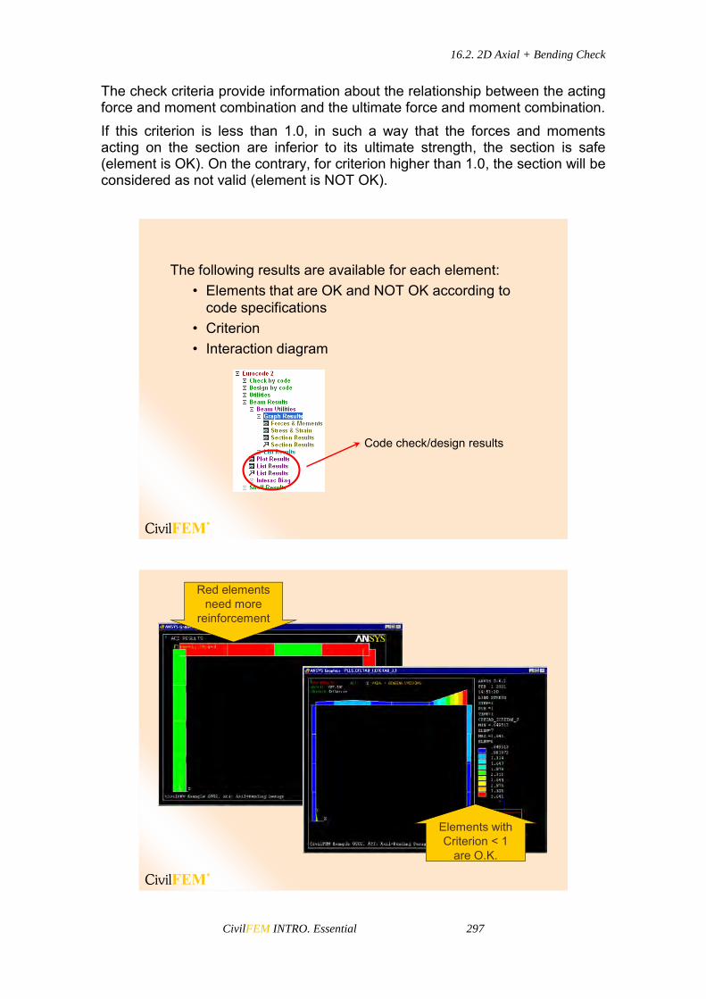
16.2. 2D Axial + Bending Check
CivilFEM INTRO. Essential 297
The check criteria provide information about the relationship between the acting force and moment combination and the ultimate force and moment combination. If this criterion is less than 1.0, in such a way that the forces and moments acting on the section are inferior to its ultimate strength, the section is safe (element is OK). On the contrary, for criterion higher than 1.0, the section will be considered as not valid (element is NOT OK).
The following results are available for each element:• Elements that are OK and NOT OK according to
code specifications• Criterion• Interaction diagram
Code check/design results
Red elements need more
reinforcement
Elements withCriterion < 1
are O.K.

16.2. 2D Axial + Bending Check
CivilFEM INTRO. Essential 298
Interaction Diagram
2D Interaction diagram
Inside OK
Outside Not OK
Without reinforcement
Ultimate strength
Design loads
This is a 2D interaction diagram. It includes all the necessary information for checking as well as design. Effects of actions, ultimate strength, safety information, as well as strength with and without reinforcement can be seen. The criterion provided is the ratio between the distances of the center of the diagram to the design loads point and the center of the diagram to the ultimate strength.
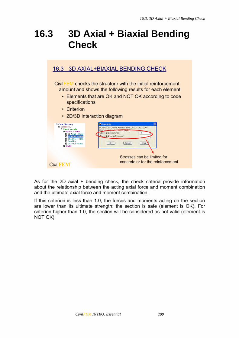
16.3. 3D Axial + Biaxial Bending Check
CivilFEM INTRO. Essential 299
16.3 3D Axial + Biaxial Bending Check
CivilFEM checks the structure with the initial reinforcement amount and shows the following results for each element:
• Elements that are OK and NOT OK according to code specifications
• Criterion• 2D/3D Interaction diagram
16.3 3D AXIAL+BIAXIAL BENDING CHECK
Stresses can be limited for concrete or for the reinforcement
As for the 2D axial + bending check, the check criteria provide information about the relationship between the acting axial force and moment combination and the ultimate axial force and moment combination. If this criterion is less than 1.0, the forces and moments acting on the section are lower than its ultimate strength: the section is safe (element is OK). For criterion higher than 1.0, the section will be considered as not valid (element is NOT OK).

16.3. 3D Axial + Biaxial Bending Check
CivilFEM INTRO. Essential 300
3D Interaction Diagram
3D Interaction diagram
Above is a 3D interaction diagram. Interaction diagram is a surface in the space (FX, MY, MZ) which defines the boundary of the failure criteria of the cross section. Therefore, this surface contains the forces and moments corresponding to the section’s ultimate strength states. It also includes all the necessary information for checking as well as design. Effects of actions, ultimate strength, safety information, and strength with and without reinforcement are also shown.

16.4. Axial + Biaxial Bending Design
CivilFEM INTRO. Essential 301
16.4 Axial + Biaxial Bending Design
Process of Reinforcement Design• In the design process all the scalable reinforcements are
multiplied by a factor so that the safety factor of the section is as close as possible to 1.00.
• Factor is taken from a range of values specified by the user. In case they are not specified, the program takes the configuration values:
min < < max (by default 0.5 2.0)
16.4 AXIAL+BIAXIAL BENDING DESIGN
• The design process follows the steps described bellow:– If the safety factor is higher than 1 for = min then min will be
used.– If the safety factor is less than 1 for = max then design fails. In
this case, the user must either increase the initial reinforcement of the section or change max.
– For other cases the factor is obtained between min and max so that safety factor is within 1.00 and 1.01.
• With CivilFEM, the results of reinforcement design are the amount of reinforcement designed and the factor for each element.

16.4. Axial + Biaxial Bending Design
CivilFEM INTRO. Essential 302
2D Axial+Bending Design of the Reinforcement
3D Axial+Bending design of the reinforcement
min and max
Selection of
bending plane
Optional stress limit
Optional stress limitmin and max
Reinforcement factor

16.5. Shear and Torsion Check and Design
CivilFEM INTRO. Essential 303
16.5 Shear and Torsion Check and Design
CivilFEM allows following types of check and design for shear and torsion:
• Shear only• Torsion only• Combined shear and torsion
16.5 SHEAR AND TORSION CHECK AND DESIGN
The Partial Safety Factors are the code comparison criteria. For example, the torsion check according to Eurocode 2 (EN 1992-1-1:2004/AC:2008) uses the following comparison parameters: TRDMAX (Maximum design torsional moment that can be resisted by the section without crushing of the concrete compressive struts, TRd,max), CRT_1 (Ratio of the design torsional moment (TEd) to the resistance TRd,max), TRD (Maximum design torsional moment that can be resisted by the torsion reinforcement, TRd) and CRT_2 (Ratio of the design torsional moment (TSd) to the resistance TRd) The Global Safety Factor takes into account all of the Partial Safety Factors and indicates the higher ratio of the design shear, torsional moment, or combined shear and torsional moment to the section’s ultimate resistance: if it is less than 1.0, the section is valid (element is OK); whereas if it exceeds 1.0, the section is not valid (element is NOT OK).
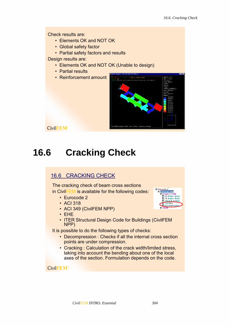
16.6. Cracking Check
CivilFEM INTRO. Essential 304
Check results are:• Elements OK and NOT OK• Global safety factor• Partial safety factors and results
Design results are:• Elements OK and NOT OK (Unable to design)• Partial results• Reinforcement amount
16.6 Cracking Check
The cracking check of beam cross sectionsin CivilFEM is available for the following codes:
• Eurocode 2• ACI 318• ACI 349 (CivilFEM NPP)• EHE• ITER Structural Design Code for Buildings (CivilFEM
NPP)It is possible to do the following types of checks:
• Decompression : Checks if all the internal cross section points are under compression.
• Cracking : Calculation of the crack width/limited stress, taking into account the bending about one of the local axes of the section. Formulation depends on the code.
16.6 CRACKING CHECK

16.7. Shell Reinforcement Check and Design
CivilFEM INTRO. Essential 305
16.7 Shell Reinforcement Check and Design
16.7 SHELL REINFORCEMENT CHECK AND DESIGNShell reinforcement works with elements SHELL43, SHELL63, SHELL93 SHELL181 and SHELL281
CivilFEM allows to design the shell reinforcement according to the following methods:
~DIMCON Command
• Wood-Armer Method• CEB-FIP Method• Orthogonal Directions
Method• Most Unfavorable Direction
MethodReinforcement amount varies in X & Y directions and in top & bottom faces for each vertex.

16.7. Shell Reinforcement Check and Design
CivilFEM INTRO. Essential 306
Wood Method
Design of reinforcement is done for MX, MY and MXY. In-plane axial and shear loads are ignored.
The orientation angles of the reinforcement can be defined for each vertex. By default ALPHA= 0.
• WOOD METHOD
Mx*
My*
Element axis
The reinforcement design of shells under bending and torsional moments is accomplished by the Wood Method. Calculation process follows these steps:
The reinforcement design moments are obtained from the acting bending moments: The bending moments Mx, My and torsional moments Mxy are provided by the shell calculation and obtained from the CivilFEM results file. Once Mx, My, and Mxy are found, a pair of design moments Mx* and My* are searched (see the picture above). These two moments are necessary for the reinforcement design and must include all the possible moments generated by Mx, My, and Mxy in any direction. Two pairs of design moments are obtained: one for the bottom reinforcement and one for top reinforcement.
The limit bending moment is calculated taking into account the active code specifications.
The reinforcement is calculated depending on if the design moment is greater or less than the limit bending moment. If the design bending moment is greater than the limit, both tension and compression reinforcements are disposed; otherwise only tension reinforcement is disposed.
Designing results are stored in the CivilFEM results file. These results are: Reinforcement amount at X top, reinforcement amount at X bottom, reinforcement amount at Y top and reinforcement amount at Y bottom.

16.7. Shell Reinforcement Check and Design
CivilFEM INTRO. Essential 307
CEB Method
Design of reinforcement taking into account :Tx, Ty, Txy, Mx, My, Mxy, Nx, Ny
• CEB-FIP 1990 METHOD
Struts andties model
The reinforcement designing of shells under bending moment and in plane loading is accomplished by model code CEB-FIP 1990. The reinforcements take an orthogonal network (directions in this network are taken as element X and Y axes). Calculation process is based on the following:
The shell is considered to be ideally divided in three layers. The outer layers provide resistance to the in plane effects of both the bending and the in plane loading; while the inner layer provides a shear transfer between the outer layers.

16.7. Shell Reinforcement Check and Design
CivilFEM INTRO. Essential 308
It assumes that the shell is reinforced with an orthogonal mesh with ax and ay separation. Therefore, the shell is divided into cells and its equivalent forces (npSdx, npSdy, vpSd) for reinforcement calculation are obtained from the acting forces and moments obtained from the CivilFEM results file.
The struts and ties method is applied to determinate the reinforcement amount from the tension of the steel bars and the compression of the concrete on each cell.
Two data are necessary: whether the reinforcing steel bars are braced or not and the angle between the reinforcement X axis (element X axis) and the direction of concrete compression. By default, = 45º (although it is valid any angle if 1/3 tan 3).

16.7. Shell Reinforcement Check and Design
CivilFEM INTRO. Essential 309
Orthogonal Directions Method
• ORTHOGONAL DIRECTIONS METHOD
Reinforcement is designed under bending moments and axial forces, for the directions of the reinforcement and independently one from the other.
Reinforcements are defined as an orthogonal net (directions of this net are taken as element X and Y axes).
Torsional moment and membrane shear force may or may not be neglected.
If they are not neglected:
*x x xy xT T T Sign(T )
*y y xy yT T T Sign(T )
*x x xy xM M M Sign(M )
*y y xy yM M M Sign(M )
Where T*x and T*
y are axial forces, Mx and My bending moments, and Mxy torsional moment and Txy membrane shear force.

16.7. Shell Reinforcement Check and Design
CivilFEM INTRO. Essential 310
X and Y represent the orthogonal directions of bending reinforcement of the shell (Element X and Y axes) Checking results will provide the criterion for the X and Y directions independently. Design results will include the reinforcement factor for each direction, top and bottom surface. Depending on the active code, the checking or design is performed using the pivot diagram described for the check and design of concrete cross sections. The maximum allowable stress in the reinforcement can be specified in order to consider ULS cracking design.
Most Unfavorable Direction Method
The aim of this design method is the calculation of the reinforcement of concrete shells with a method based on the one proposed by Capra-Maury which takes into account bending moments (Mxx, Myy) and torsional moments (Mxy) as well as axial forces (Nxx, Nyy) and in plane shear forces (Nxy).
• MOST UNFAVORABLE DIRECTION METHOD
A group of top (Axt, Ayt) and bottom (Axb, Ayb) reinforcements will be obtained balancing the bending moment and axial force (M, N) projected on a plane with its normal contained in the shell.
To solve it, the total bottom reinforcement and the total top reinforcement are minimized independently.
Reinforcements are considered to be orthogonal and set along the X and Y axes of the element. Considering a plane with its normal contained in the shell and located at an angle from the positive X axis of the element, the bending moment and axial force (M, N) are:
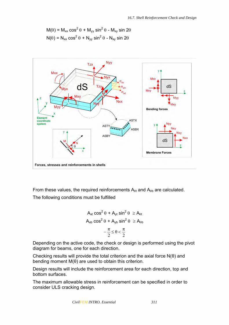
16.7. Shell Reinforcement Check and Design
CivilFEM INTRO. Essential 311
M() = Mxx cos2 + Myy sin2 - Mxy sin 2
N() = Nxx cos2 + Nyy sin2 - Nxy sin 2
From these values, the required reinforcements At and Ab are calculated. The following conditions must be fulfilled
Axt cos2 + Ayt sin2 At
Axb cos2 + Ayb sin2 Ab
2πθ
2π
Depending on the active code, the check or design is performed using the pivot diagram for beams, one for each direction. Checking results will provide the total criterion and the axial force N(θ) and bending moment M(θ) are used to obtain this criterion. Design results will include the reinforcement area for each direction, top and bottom surfaces. The maximum allowable stress in reinforcement can be specified in order to consider ULS cracking design.
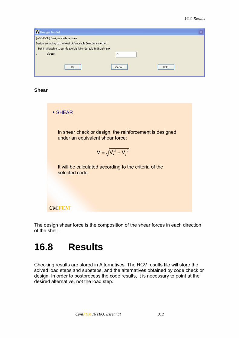
16.8. Results
CivilFEM INTRO. Essential 312
Shear
• SHEAR
In shear check or design, the reinforcement is designed under an equivalent shear force:
It will be calculated according to the criteria of the selected code.
2 2x yV V V
The design shear force is the composition of the shear forces in each direction of the shell.
16.8 Results
Checking results are stored in Alternatives. The RCV results file will store the solved load steps and substeps, and the alternatives obtained by code check or design. In order to postprocess the code results, it is necessary to point at the desired alternative, not the load step.

16.8. Results
CivilFEM INTRO. Essential 313
• Partial results of the calculation according to the selected code
• Total criteria• Elements OK and NOT OK• Reinforcement amount or scaling factor (design)
16.8 RESULTSBEAM RESULTS
SHELL RESULTS
An icon shows the reinforcement location
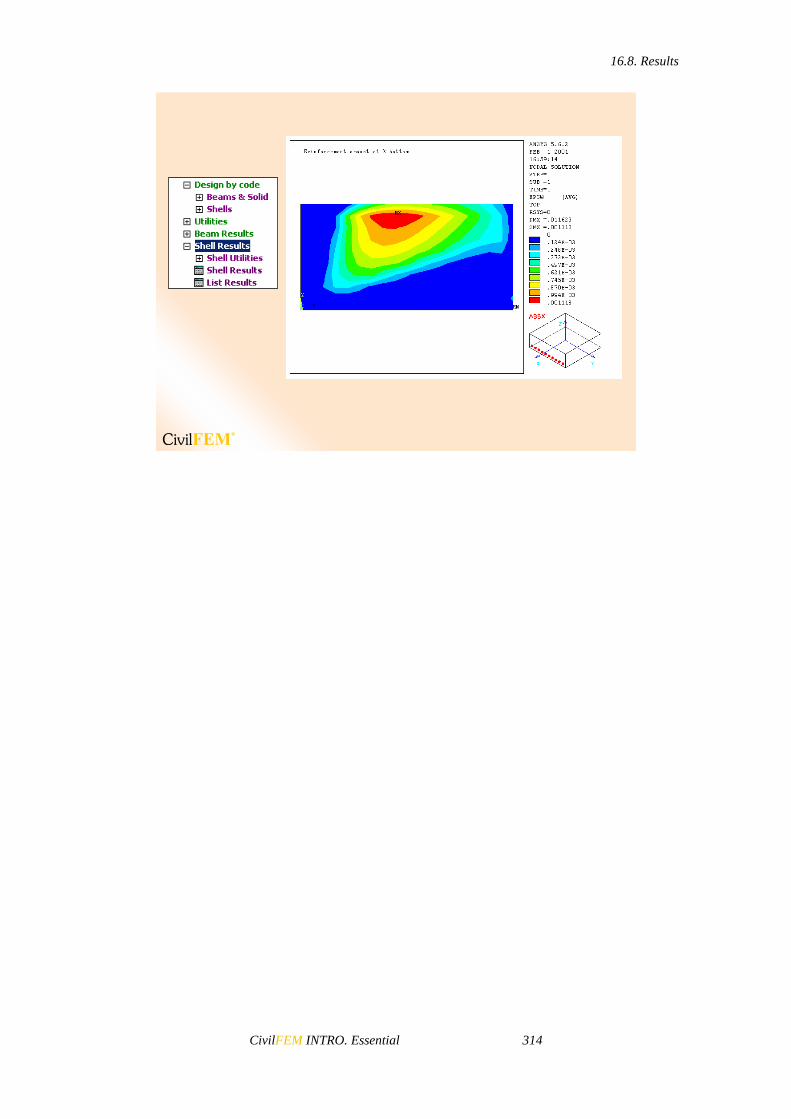
16.8. Results
CivilFEM INTRO. Essential 314

CivilFEM INTRO. Essential 315
17 CivilFEM Steel Checking


17.1. General concepts
CivilFEM INTRO. Essential 317
17.1 General concepts
With CivilFEM it is possible to accomplish steel code checks according to the different design codes for steel structures.
It is possible to check any cross-section defined using any of the CivilFEM available methods, including the cross-sections defined by plates.
17.1 General Concepts
CivilFEM has the following codes implemented:
• Eurocode 3• CTE DB SE-A (Spanish)• EA-95 (Spanish)• AISC-LRFD 2nd Edition• AISC-LRFD 13th Edition• AISC-ASD 13th Edition• AISC-ASD 9th Edition (CivilFEM NPP)• British Standard 5950 (1985 & 2001)• GB50017 (Chinese)• ASME BPVC Sect.III Div.1 SubSection NF (1989) (CivilFEM NPP)• ANSI/AISC N690-1994 (CivilFEM NPP)• ANSI/AISC N690-2006 ASD and LRFD provisions (CivilFEM NPP)
Each code uses different criteria and methods as shown hereafter.

17.2. Eurocode 3
CivilFEM INTRO. Essential 318
17.2 Eurocode 3
Eurocode 3
Types of checkingTension (1D): FX+
Compression (1D): FX-
Bending (2D): MZ or MY
Shear (2D): FY or FZ
Bending + shear (2D): (FY, MZ) or (FZ, MY)
Bending + Axial (3D): FX, MY, MZ
Bending + Axial + Shear (3D): FX, FY, FZ, MY, MZ
Compression Buckling (1D): FX-
Lateral Buckling (2D): MZ or MY
Lateral Buckling in Bending + Tension (3D): FX+, (MY or MZ)
Buckling in Bending + Compression (3D): FX-, MY, MZ
Y
Z
Y
Z
Y
ZG.C.
For studying the safety of the structure, Eurocode 3 classifies sections in 4 possible classes: Class 1 Cross-sections that can form a plastic hinge with the rotation
capacity required for plastic analysis. Class 2 Cross-sections that can reach their plastic moment resistance,
but have limited rotation capacity. Class 3 Cross-sections in which the stress in the extreme compression
fiber of the steel member can reach its yield strength, but local buckling is liable to prevent development of the plastic moment resistance.
Class 4 Cross-sections in which it is necessary to make explicit allowances for the effects of local buckling when determining their moment resistance or compression resistance.

17.2. Eurocode 3
CivilFEM INTRO. Essential 319
Class 1• Mu = fy * Wplastic
• It can form a plastic hinge
Class 2• Mu = fy * Wplastic
• Limited rotation capacity
Class 3• Mu = fy * Welastic
• Only elastic solutions
Class 4• Mu < fy * Welastic
• Only elastic solutions
Compact Sections Slender Sections
Class 1 Class 2 Class 3 Class 4
In class 4 sections, the section resistance is reduced: for each section plate, the effective lengths at both ends of the plate and the reduction factors 1 and 2 are calculated.
Selection of the section
to plot
Axis selectionPlot options
Section forcesand moments list
Plates list
Non-effective segment
The program takes into account the reduction in the resistance of slender sections (class 4) due to local buckling.
Class 4 section
CivilFEM considers and works with three different coordinate reference systems. All of these systems are right-handed:

17.2. Eurocode 3
CivilFEM INTRO. Essential 320
1. CivilFEM Reference Axis. (blue axis). 2. Cross-Section Reference Axis. (pink axis). 3. Eurocode 3 Reference Axis. (Code axis). (green axis).
To define the Eurocode 3 reference system, the user must indicate which of the CivilFEM axis: -Z, -Y, +Z or +Y coincides with the relevant axis for positive bending.
Class Calculation:• Partial: Check only takes into account the forces and moments corresponding to the check being executed.• Full: Check takes into account all forces and moments.
Specify the mainaxis for bending
ClassCalculation
Notes• According to Eurocode 3, CivilFEM checks:
– Section resistance– Local buckling of the section plates– Element buckling with the method
• Results and safety factors depend on the selected axis for the check.
• Eurocode 3 changes its sign criteria according to the two cases:
– In compression checking, compression is taken as positive.– In tension checking, tension is taken as positive.

17.3. EA-95
CivilFEM INTRO. Essential 321
17.3 EA-95
Types of Checks:
Tension (1D): FX+
Compression (1D): FX-
Bending (2D): MZ or MY
EA-95
17.4 BS 5950
Bending + Shear (2D): (FY, MZ) or (FZ, MY)
Lateral Buckling (2D): MZ or MY
Tension (1D): FX+
Compression Buckling (1D): FX-
Bending + Tension + Shear (3D): FX, FY, FZ, MY, MZ
Bending + Compression + Shear (3D): FX, FY, FZ, MY, MZ
Y
Z
Y
Z
Y
XG.C.
Types of Checks:
BS 5950 (1985 and 2001)

17.4. BS 5950
CivilFEM INTRO. Essential 322
CivilFEM, when performing checks according to BS 5950, considers and works with three different coordinate systems. All of these systems are right-handed:
1. CivilFEM Reference Axis (blue axis). 2. Cross-Section Reference Axis (pink axis). 3. BS 5950 Reference Axis (Code Axis), (green axis).
Specify the main axis for bending
Y
Z
Y
Z
Y
XG.C.
To define this reference system, the user must indicate which direction of the CivilFEM axis: -Z, -Y, +Z or +Y coincides with the relevant axis for positive bending. The steps for the checking process are as follows:
1. Read the checking type requested by the user. 2. Read the CivilFEM axis to be considered as the principal bending
axis in order to coincide with the X-axis of BS5950. 3. Checking operations for each element:
Obtain material properties stored in the CivilFEM database corresponding to the element and calculate the rest of the properties needed for checking: Shear Modulus, Epsilon (material coefficient).
Obtain the cross-section data corresponding to the element.
Determine of the section class (similar classification to Eurocode 3) and calculate the reduction factors applied to the design strength in the case of slender sections.
Obtain forces acting on the section (Fx, Fvx, Fvy, Mx, My).

17.5. AISC-LRFD and ASIC-ASD
CivilFEM INTRO. Essential 323
Check the specific section according to the type of external load.
Document the results which will be stored in the CivilFEM results file (.RCV) as an alternative.
17.5 AISC-LRFD and ASIC-ASD
TensionCompression for flexural bucklingCompression for flexural-torsional bucklingBendingShearPlate GirdersBending + AxialBending + Axial + Shear + Torsion
Types of Checks:
AISC-LRFD (2nd Edition)
TensionCompression for flexural bucklingCompression for flexural-torsional bucklingBendingShearAxial compression + BendingAxial tension + Bending
Types of Checks:
AISC-ASD (9th Edition)

17.5. AISC-LRFD and ASIC-ASD
CivilFEM INTRO. Essential 324
TensionCompression for flexural bucklingCompression for flexural-torsional bucklingBendingShearPlate GirdersBending + AxialBending + Axial + Shear + Torsion
Types of Checks:
AISC-LRFD and AISC-ASD (13th Edition)

17.6. ANSI/AISC N690
CivilFEM INTRO. Essential 325
17.6 ANSI/AISC N690
TensionCompression for Flexural BucklingCompression for Flexural-Torsional BucklingBendingShearPlate GirdersBending + AxialBending + Axial + Shear + Torsion
Types of Checks:
ANSI/AISC N690-2006 ASD and LRFD provisions
TensionCompression for Flexural BucklingCompression for Flexural-Torsional BucklingBendingShearAxial Compression + BendingAxial Tension + Bending
Types of Checks:
ANSI/AISC N690-1994

17.7. GB50017
CivilFEM INTRO. Essential 326
17.7 GB50017
BendingShearBending + ShearAxial ForceBending + AxialCompression Buckling
Types of Checks:
GB50017
17.8 CTE DB SE-A
TensionCompressionBendingShearBending + Axial ForceBending + ShearBending + Axial Force + ShearCompression BucklingBending BucklingBending + Tension BucklingBending + Compression Buckling
Types of Checks:
CTE DB SE-A

17.9. ASME BPVC Section III Div.1 SubSection NF (1989)
CivilFEM INTRO. Essential 327
17.9 ASME BPVC Section III Div.1 SubSection NF (1989)
TensionShearCompressionBendingBending + Axial CompressionBending + Axial Tension
Types of Checks:
ASME BPVC Sect. III Div.1 SubSection NF (1989)


CivilFEM INTRO. Essential 329
18 CivilFEM Envelopes


18.1. Alternatives and Envelopes
CivilFEM INTRO. Essential 331
18.1 Alternatives and Envelopes
The data in the CivilFEM results file are stored in two different types of data blocks: blocks of stresses, forces, moments, and strains and blocks of alternatives. Data blocks of stresses, forces, moments, and strains are obtained and stored immediately after solving. Blocks of alternatives differ from each other in their content because they depend on the process (type of check or design) that has generated the alternative. These data are created in postprocessing phase, taking input data of forces, moments, stresses, and strains from the corresponding blocks. Each block of forces, moments, stresses, and strains may generate one or more alternative blocks.
~ENVELOP
• This utility allows the generation of new alternatives as an envelope of others previously obtained. There are three types of envelopes: maximum values, minimum values , and absolute values.
• Envelopes have to be homogeneous: each must be obtained by the application of the same code and the processing of the same model. The resulting alternative will be homogeneous with the previous ones, possessing a similar identification and the same reading, drawing and representation commands.
StressesStrainsForcesMoments
RCV.File
Alternative 1
StressesStrainsForcesMoments
RCV.File
Alternative 1Alternative 2Alternative 3
Alternative 2
18.1 Alternatives and Envelopes
The envelope of several alternatives is a new data block (new alternative) that contains the minimum, maximum or absolute maximum values (depending on type) of each input alternatives.


CivilFEM INTRO. Essential 333
19 CivilFEM Seismic Design


19.1. Time or Frequency Domain?
CivilFEM INTRO. Essential 335
19.1 Time or Frequency Domain?
19.1 Time or Frequency Domain?
Time
• All Types of Analysis- Non Linear- Any Damping
• Easy Concepts- Few concepts differ from a
static analysis
• Difficult Calculation- Calculation time is high- Disc space needed is high
Frequency
Valid for Some Analyses- Linear Analysis- Simplified Damping
New Concepts- Mode shapes- Spectrum, Eigenvalues…
Easy Calculation Better phenomena
comprehension
19.2 Frequency Domain
19.2 Frequency Domain
• Modal AnalysisThis method allows the user to obtain the natural frequencies and mode shapes of a structure. It functions well as a first evaluation, but sometimes is insufficient.
• Harmonic AnalysisUseful when actions are cyclic, have the same frequency and act indefinitely.
• Spectral Analysis by Modal SuperpositionThe response of the structure is characterized by the combination of some of the natural mode shapes of the structure, multiplied by a coefficient that comes from the spectrum.
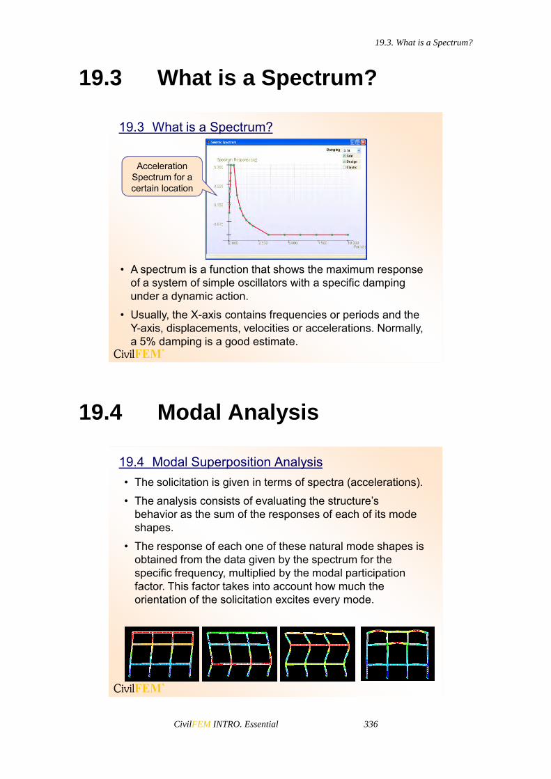
19.3. What is a Spectrum?
CivilFEM INTRO. Essential 336
19.3 What is a Spectrum?
19.3 What is a Spectrum?
• A spectrum is a function that shows the maximum response of a system of simple oscillators with a specific damping under a dynamic action.
• Usually, the X-axis contains frequencies or periods and the Y-axis, displacements, velocities or accelerations. Normally, a 5% damping is a good estimate.
Acceleration Spectrum for a certain location
19.4 Modal Analysis
19.4 Modal Superposition Analysis• The solicitation is given in terms of spectra (accelerations).
• The analysis consists of evaluating the structure’s behavior as the sum of the responses of each of its mode shapes.
• The response of each one of these natural mode shapes is obtained from the data given by the spectrum for the specific frequency, multiplied by the modal participation factor. This factor takes into account how much the orientation of the solicitation excites every mode.
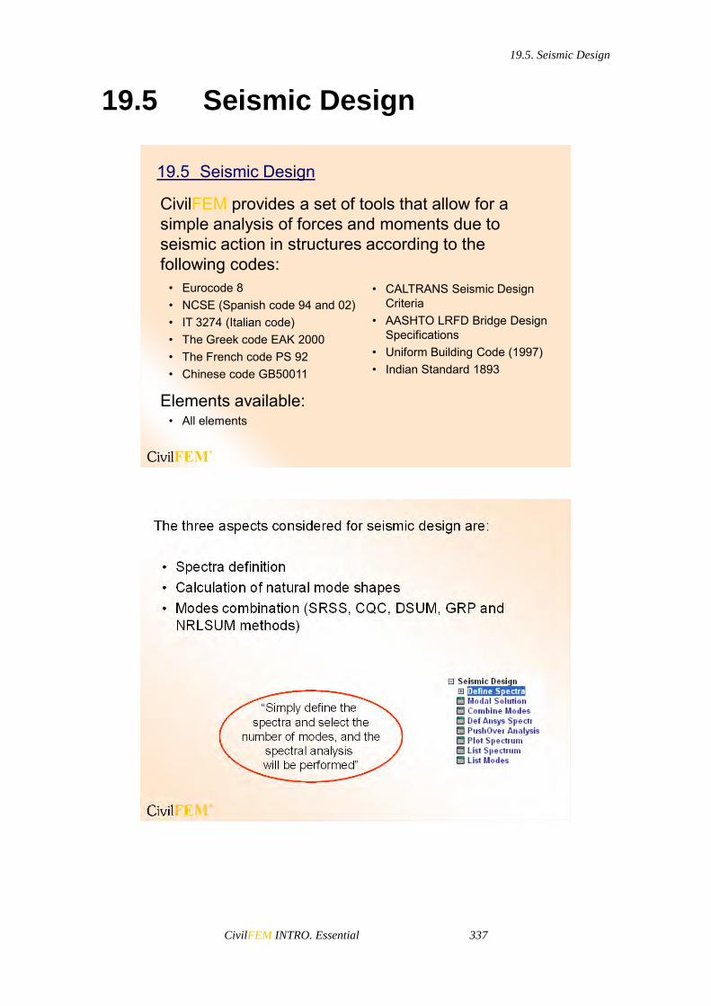
19.5. Seismic Design
CivilFEM INTRO. Essential 337
19.5 Seismic Design
CivilFEM provides a set of tools that allow for a simple analysis of forces and moments due to seismic action in structures according to the following codes:
Elements available:• All elements
19.5 Seismic Design
• Eurocode 8• NCSE (Spanish code 94 and 02)• IT 3274 (Italian code)• The Greek code EAK 2000 • The French code PS 92 • Chinese code GB50011
• CALTRANS Seismic Design Criteria
• AASHTO LRFD Bridge Design Specifications
• Uniform Building Code (1997) • Indian Standard 1893

19.5. Seismic Design
CivilFEM INTRO. Essential 338
CivilFEM builds and defines the response spectrum from a certain code with the parameters that define it.
The data required to define the response spectrum are input into the CivilFEMdatabase with the ~DEFSPEC command.
Four spectra can be defined for different damping values.
Up to four spectra may be defined with different damping ratios. Each of the spectra may be created using different code options, but only the last ones used will be listed.
• It is also possible to define the spectra by points:
• First, the periods must be defined in ascending order.• Then, for each of the damping values, different
accelerations can be provided to define the different spectra.

19.5. Seismic Design
CivilFEM INTRO. Essential 339
The procedure to define the spectra by points is:
Define the horizontal periods in ascending order.
Next, the horizontal acceleration values may be defined for the previously set periods. Up to four spectra may be defined, each one for a different damping value. All of these spectra have the same period table.
Define the vertical periods in ascending order.
For the vertical period table, the vertical acceleration values may be defined in the same way as for the horizontal values.
The number of modes to be extracted can be defined with the command ~MODLSOL. The default is 20 modes.The number of mode shapes to be calculated is taken as input data for the modal analysis of the structure that is carried out in ANSYS.

19.5. Seismic Design
CivilFEM INTRO. Essential 340
Both the abscissas and ordinates of the spectrum can be listed and plotted with the commands ~L_SPEC and ~P_SPEC.
Spectrum componentto be drawn
Initial period
Finalperiod Increments

19.5. Seismic Design
CivilFEM INTRO. Essential 341
Modes Combination
Once the vibration modes are obtained by means of the ~CMBMOD command, they are combined in the indicated directions.
The combination of vibration modes can be done with the command ~CMBMOD.
To use this command, the spectrum data must be defined and the vibration modes to be combined extracted.
The combination result is stored in CivilFEM´s results file (file.RCV) with a Load Step number following the last Load Step carried out.
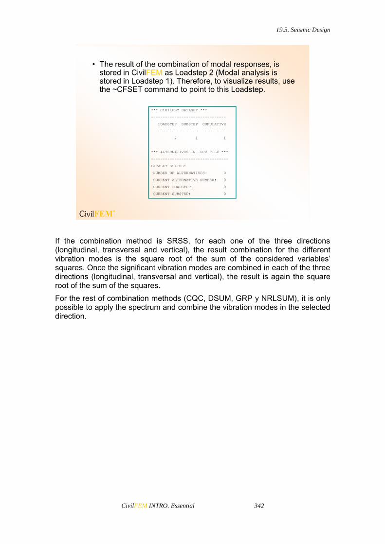
19.5. Seismic Design
CivilFEM INTRO. Essential 342
*** CivilFEM DATASET ***
--------------------------------
LOADSTEP SUBSTEP CUMULATIVE
-------- ------- ----------
2 1 1
*** ALTERNATIVES IN .RCV FILE ***
---------------------------------
DATASET STATUS:
NUMBER OF ALTERNATIVES: 0
CURRENT ALTERNATIVE NUMBER: 0
CURRENT LOADSTEP: 0
CURRENT SUBSTEP: 0
• The result of the combination of modal responses, is stored in CivilFEM as Loadstep 2 (Modal analysis is stored in Loadstep 1). Therefore, to visualize results, use the ~CFSET command to point to this Loadstep.
If the combination method is SRSS, for each one of the three directions (longitudinal, transversal and vertical), the result combination for the different vibration modes is the square root of the sum of the considered variables’ squares. Once the significant vibration modes are combined in each of the three directions (longitudinal, transversal and vertical), the result is again the square root of the sum of the squares. For the rest of combination methods (CQC, DSUM, GRP y NRLSUM), it is only possible to apply the spectrum and combine the vibration modes in the selected direction.
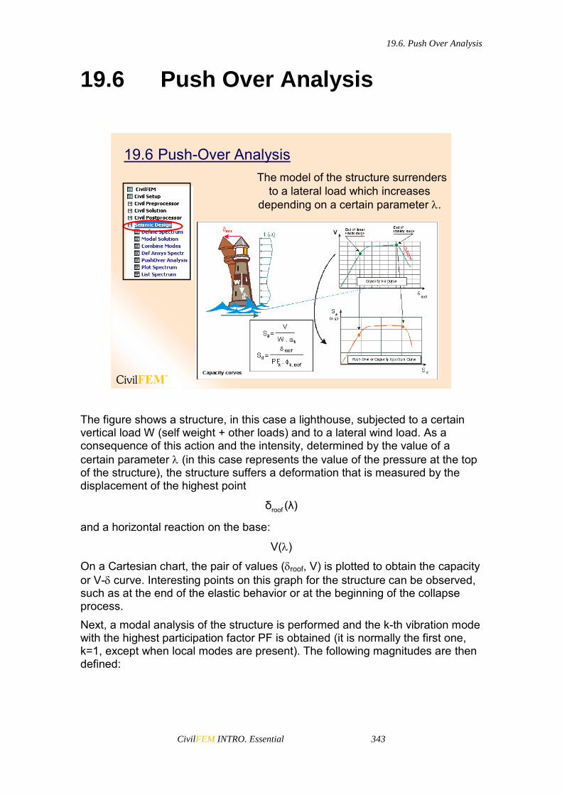
19.6. Push Over Analysis
CivilFEM INTRO. Essential 343
19.6 Push Over Analysis
19.6 Push-Over AnalysisThe model of the structure surrenders
to a lateral load which increases depending on a certain parameter .
The figure shows a structure, in this case a lighthouse, subjected to a certain vertical load W (self weight + other loads) and to a lateral wind load. As a consequence of this action and the intensity, determined by the value of a certain parameter (in this case represents the value of the pressure at the top of the structure), the structure suffers a deformation that is measured by the displacement of the highest point
roofδ (λ)
and a horizontal reaction on the base:
V()
On a Cartesian chart, the pair of values (roof, V) is plotted to obtain the capacity or V- curve. Interesting points on this graph for the structure can be observed, such as at the end of the elastic behavior or at the beginning of the collapse process. Next, a modal analysis of the structure is performed and the k-th vibration mode with the highest participation factor PF is obtained (it is normally the first one, k=1, except when local modes are present). The following magnitudes are then defined:

19.6. Push Over Analysis
CivilFEM INTRO. Essential 344
N
i iki 1
k N2
i iki 1
m PF
m
(Modal Mass Coefficient)
2N
i iki 1
k N N2
i i iki 1 i 1
m α
m m
(Modal Participation Factor)
In these expressions ik is the i-th component of the vibration mode k, and mi is the mass that corresponds to the associated degree of freedom. The vibration modes are normalized, so that:
N2
i iki 1
m 1
(N = total number of degrees of freedom)
The previous expressions are simplified:
N
k i iki 1
2k
PF m
PFαk (W/g)
To carry out the Push Over analysis, a change of variables is made from the roof –V diagram built before, to a new Sd – Sa diagram called Acceleration-Displacement Response Spectrum or ADRS. The change of variables is
ak
roofd
k k,roof
VSW
δSPF .
Both curves can be seen in the previous figure. The following figure shows usual values of the previously defined parameters for different shapes of the dominant vibration mode k.

19.6. Push Over Analysis
CivilFEM INTRO. Essential 345
Therefore:
Response spectra are usually set in terms of accelerations (Sa), pseudovelocities (Sv) or displacements (Sd) corresponding with the vibration period T. Between these four magnitudes, the following relationships can be set
a v d v2π TS g = S , S ST 2π
when Sa is expressed as fractions of g. Removing Sv from the previous expressions, the following equation is obtained:
2
d a2TS g S
4π
This equation sets the relationship between the acceleration and displacements spectra. The following figure represents the acceleration spectra in its standard expression (T, Sa), and from this figure, the (Sd, Sa) spectra ADSR is obtained.

19.6. Push Over Analysis
CivilFEM INTRO. Essential 346
Sa
T
Standard Format Spectrum
ZPA(Rigid body acceleration) Sa
Sd
T=T1 T=T2
T=T3
ADRS Format
S aS = ______d
T g2
2
Response Spectra
(x g)
(x g)
Sd/Sa = c , (constant) The lines depicted through the origin represent, in this plane, the locus of an equal vibration period:
d
a
S cT = 2π 2πg S g
With lower values of T, the structure is stiffer. In fact, the value of Sa for T = 0 is known as ZPA (zero period acceleration), so the value
a
d
S1kc S
for these straight lines is a measure of the stiffness.

19.6. Push Over Analysis
CivilFEM INTRO. Essential 347
Superposing the Capacity Spectrum Curves (CSC) and the Demand Spectrum Curve (DSC) with (Sd, Sa) axes obtains the following graph:
Capacity Spectrum Curve
Demand Spectrum Curve
Elastic Point
Inelastic Point (IP)
Superposing the Capacity Spectrum curve with the Demand Spectrum Curve in the (Sd, Sa) graph.
Performance Point (PP)
If the structure remains elastic during the entire load process, the intersection point of the CSC and DSC curves (capacity and demand), known as the Performance Point (PP), represents the equilibrium situation. This is to say, pp would be the deformation that would be obtained when the seismic forces act on the structure. Nevertheless, in general, the structure does not remain in an elastic regime during the whole process. For this reason, several authors prefer to consider the Inelastic Point (IP) as a working point in presence of seismic forces, obtained as shown in the previous figure. It is therefore equivalent to conclude that when regarding displacements, the structure maintains its elastic behaviour until its intersection with the demand curve. During the process, plastic local phenomena take place which cause the weakening of the structure.
For example: a load applied to a structure is increased by a multiplier factor i (i > j if i > j).

19.6. Push Over Analysis
CivilFEM INTRO. Essential 348
x 2 x 3 x 4 x 51 ( )x 1
A C
B D
P Q
Elastic behaviour
Plastic behaviour
Retrofit Analysis
Sa
Sd
T=T1 T=T2
T=T3
(x g)
PP (Performance Point)
1
2
34
5
T=TI
If < 2 the structure stays elastic with a stiffness that is determined by the straight line corresponding to the period T = TI.
If =2 the PC bar becomes plastic.
If = 4 the structure is weakened because both the AP and PC bars have undergone yielding.
If = 5 the structure collapses. With this analysis it is possible to determine where the structure needs to be strengthened. The Push Over analysis consists of several steps:
1. Creation of the finite element model.
2. Response Spectrum and modal analysis.
3. Definition of the vertical loads which remain constant during the process.
4. Definition of the horizontal loads that will be increased by the parameter . These loads are stored in a load file (~CFLSWRT command).
5. Definition of a range for the parameter: (i, f ) and the increment. (~PUSHDEF command)
6. Selection of the predominant mode. (~PUSHMOD command).

19.6. Push Over Analysis
CivilFEM INTRO. Essential 349
7. Calculation of the structure submitted to the loads defined in 3 and 4, changing (~PUSHSLV command).
8. Selection of a stage (across Sd or ) and a graphic representation (~RETROFT command).
The results can be listed using the ~PUSHLST command.
General DataCoordinates
of nodeNumber of node
Load state file
Vertical axis
Number of substeps
Load multiplier factor
~PUSHDEF command
Disp. Measure Point: The Push Over curves will be defined with the displacement found at this point. It may be defined by node coordinates or by the node number.
LS File: Load state file that contains the loads placed on the structure that will be increased by the multiplier factor.
Lambda: load multiplier factor.
SS num: Number of substeps. For every substep, the load will be increased by / SS num. (For example, if there are 10 substeps and =5, 1 =0.5 2 = 1 3 =1.5 …10 =5, then the load is multiplied by 1 in the first load state, by 2 in the second load state, etc…)
Vertical Axis: A vertical axis must be defined (direction of gravity).

19.6. Push Over Analysis
CivilFEM INTRO. Essential 350
Modal Shape
Solve
Selected mode shape
(~PUSHMOD and~PUSHSLV commands)
Plot
PerformancePoint
Inelastic Point
Elastic Point
Curves
Lambda or Sd Values
(~RETROFTCommand)
PP (performance point): Intersection point of the curves. EP (elastic point): Intersection point of the curves if the structure had an
elastic behaviour. IP (inelastic point): Point of the capacity curve vertically above the EP.
After introducing the values of Sd or the multiplier factor Lambda in the RETROFIT area of the window, the yielding of the structure is represented in the graphic window for a specific substep.

19.6. Push Over Analysis
CivilFEM INTRO. Essential 351
Yielded elements
Through commands this can be done by entering: ~RETROFIT, Lambda, VALUE Or ~RETROFIT, Sd, VALUE
~RETROFT, Lambda, VALUEto view the yielding of the structure
for each substep.


CivilFEM INTRO. Essential 353
20 CivilFEM Further Training


20.1. Documentation
CivilFEM INTRO. Essential 355
20.1 Documentation
20.1 Documentation• ANSYS documentation:
– ANSYS Element Reference– ANSYS Commands Reference– Analysis Procedures– ANSYS Theory Reference– APDL Programmer's Guide– ANSYS Tutorials
• CivilFEM documentation:– CivilFEM Commands Reference– CivilFEM Theory Manual– CivilFEM Dialog Boxes– Workbook– Manual of Exercises– Manual of Essential Examples– Advanced Examples
Exercises
Start > Programs >CivilFEM > Help
Start > Programs >ANSYS > Help
20.2 Element Types
20.2 Element TypesANSYS has a library of over 200 element types to choose from. Some of the commonly used ones are: Plane, Solid, Beam, Pipe, Shell, Link, Surface, Mesh, Contact, Target …
The elements most commonly used in Civil Engineering are: Plane, Solid, Beam, Shell and Link elements.
You can find descriptions of the elements (their characteristics, restrictions, field application, etc.) in the Element Reference in ANSYS help or by typing HELP,”element type name” at the command prompt.

20.3. Analysis Types
CivilFEM INTRO. Essential 356
20.3 Analysis Types
20.3 Analysis Types• Structural
– Static (ANSYS help > Structural Analysis Guide > Chapter 2)– Modal (ANSYS help > Structural Analysis Guide > Chapter 3)– Harmonic (ANSYS help > Structural Analysis Guide > Chapter 4)– Transient Dynamic (ANSYS help > Structural Analysis Guide > Chapter 5)– Spectrum (ANSYS help > Structural Analysis Guide > Chapter 6)– Buckling (ANSYS help > Structural Analysis Guide > Chapter 7)
• Thermal (ANSYS help > Thermal Analysis Guide)• Fluid Flow (ANSYS help > Fluids Analysis Guide)• Electromagnetic
– Low-Frequency Analysis (ANSYS help > Low-Frequency Electromagnetic Guide)
– High-Frequency Analysis (ANSYS help > High-Frequency Electromagnetic Guide)
• Coupled-Field (Multiphysics) (Considers the mutual interaction between two or more fields) (ANSYS help > Coupled-Field Analysis Guide)