ethernet/ip - 産業用ロボット・電動アクチュエータ …me0278-10d).pdf• ethernet/ip...
TRANSCRIPT
EtherNet/IP
IAI America, Inc.
Operation Manual, Tenth EditionDescribes Model
ACON C/CG/CA/CB/CGB
PCONC/CG/CA/CFA CB/CFB/CGB/CGFB
DCON CA/CB/CGB
SCONCA/CAL/CGAL/ CB/CGB (Servo Press)

Please Read Before Use Thank you for purchasing our product. This operation manual explains the handling methods, structure and maintenance of this product, among others, providing the information you need to know to use the product safely. Before using the product, be sure to read this manual and fully understand the contents explained herein to ensure safe use of the product. The DVD that comes with the product contains operation manuals for IAI products. When using the product, refer to the necessary portions of the applicable operation manual by printing them out or displaying them on a PC. After reading the operation manual, keep it in a convenient place so that whoever is handling this product can reference it quickly when necessary.
[Important] • This operation manual is original. • The product cannot be operated in any way unless expressly specified in this operation manual. IAI shall
assume no responsibility for the outcome of any operation not specified herein. • Information contained in this operation manual is subject to change without notice for the purpose of product
improvement. • If you have any question or comment regarding the content of this manual, please contact the IAI sales office
near you. • Using or copying all or part of this operation manual without permission is prohibited. • The company names, names of products and trademarks of each company shown in the sentences are
registered trademarks. • EtherNet/IP is a trademark used under ODVA licenses.

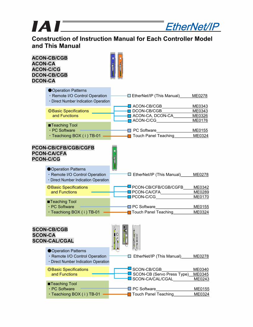
Construction of Instruction Manual for Each Controller Model and This Manual ACON-CB/CGBACON-CAACON-C/CGDCON-CB/CGBDCON-CA
PCON-CB/CFB/CGB/CGFBPCON-CA/CFAPCON-C/CG
SCON-CB/CGBSCON-CASCON-CAL/CGAL
●Operation Patterns・Remote I/O Control Operation EtherNet/IP (This Manual) ME0278・Direct Number Indication Operation
ACON-CB/CGB ME0343◎Basic Specifications DCON-CB/CGB ME0343
and Functions ACON-CA, DCON-CA ME0326ACON-C/CG ME0176
■Teaching Tool・PC Software PC Software ME0155・Teachiong BOX ( i ) TB-01 Touch Panel Teaching ME0324
●Operation Patterns・Remote I/O Control Operation EtherNet/IP (This Manual) ME0278・Direct Number Indication Operation
◎Basic Specifications PCON-CB/CFB/CGB/CGFB ME0342and Functions PCON-CA/CFA ME0289
PCON-C/CG ME0170■Teaching Tool・PC Software PC Software ME0155・Teachiong BOX ( i ) TB-01 Touch Panel Teaching ME0324
●Operation Patterns・Remote I/O Control Operation EtherNet/IP (This Manual) ME0278・Direct Number Indication Operation
◎Basic Specifications SCON-CB/CGB ME0340and Functions SCON-CB (Servo Press Type) ME0345
SCON-CA/CAL/CGAL ME0243■Teaching Tool・PC Software PC Software ME0155・Teachiong BOX ( i ) TB-01 Touch Panel Teaching ME0324
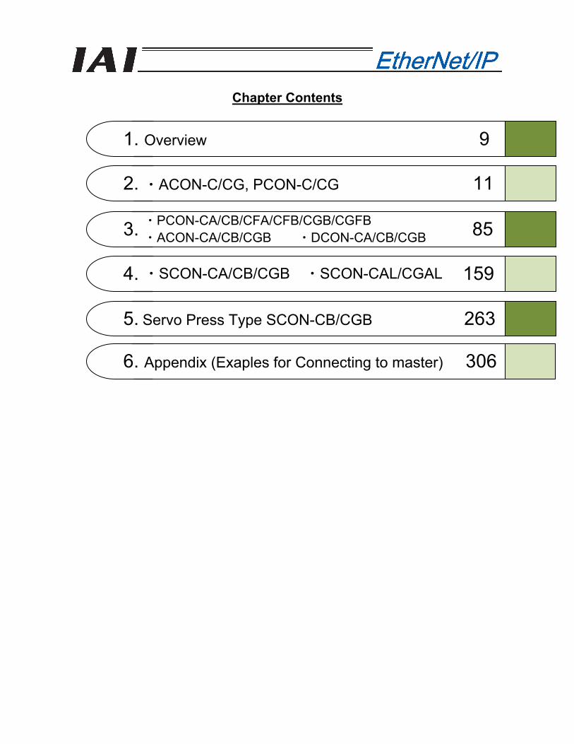
Chapter Contents
1. Overview 9
2. ・ACON-C/CG, PCON-C/CG 11
3. 85
4. 159
5. Servo Press Type SCON-CB/CGB 263
・PCON-CA/CB/CFA/CFB/CGB/CGFB ・ACON-CA/CB/CGB ・DCON-CA/CB/CGB
・SCON-CA/CB/CGB ・SCON-CAL/CGAL
6. Appendix (Exaples for Connecting to master) 306
Table of Contents
Safety Guide ....................................................................................................................................................1 Handling Precautions ......................................................................................................................................8
1. Overview.................................................................................................................................................9 1.1 EtherNet/IP Specifications...........................................................................................................10
2. ACON-C/CG, PCON-C/CG ..................................................................................................................11 2.1 Operation Modes and Functions .................................................................................................11 2.2 Model Numbers ...........................................................................................................................14 2.3 EtherNet/IP Interface ...................................................................................................................15
2.3.1 Names of the Parts.............................................................................................................15 2.3.2 Monitor LED Indications .....................................................................................................16
2.4 Wiring Example ...........................................................................................................................17 2.4.1 Connection Diagram...........................................................................................................17 2.4.2 Connector Pin Layout.........................................................................................................17
2.5 Setting..........................................................................................................................................18 2.5.1 Operation Mode Selecting..................................................................................................18 2.5.2 Setting the Baud Rate ........................................................................................................18 2.5.3 Setting the IP Address........................................................................................................18 2.5.4 Setting the Subnet Mask ....................................................................................................19 2.5.5 Setting the Default Gateway...............................................................................................19
2.6 Communicating with the Master Station......................................................................................20 2.6.1 Operation Modes and Corresponding PLC I/O Areas........................................................20 2.6.2 Remote I/O Mode (Number of Occupied Bytes: 2) ............................................................22 2.6.3 Position/Simplified Direct Value Mode (Number of Occupied Bytes: 8).............................28 2.6.4 Half Direct Value Mode (Number of Occupied Bytes: 16)..................................................33 2.6.5 Full Direct Value Mode (Number of Occupied Bytes: 32) ..................................................40 2.6.6 Remote I/O Mode 2 (Number of Occupied Bytes: 12) .......................................................49 2.6.7 I/O Signal Controls and Function .......................................................................................53
2.7 I/O Signal Timings .......................................................................................................................70 2.8 Operation.....................................................................................................................................71 2.9 EtherNet/IP Related Parameters.................................................................................................79 2.10 Troubleshooting...........................................................................................................................84
3. ACON-CA/CB/CGB, PCON-CA/CB/CFA/CFB/CGB/CGFB, DCON-CA/CB/CGB ...............................85 3.1 Operation Modes and Functions .................................................................................................85 3.2 Model Numbers ...........................................................................................................................88 3.3 EtherNet/IP Interface ...................................................................................................................89
3.3.1 Names of the Parts.............................................................................................................89 3.3.2 Monitor LED Indications .....................................................................................................89
3.4 Wiring Example ...........................................................................................................................90 3.4.1 Connection Diagram...........................................................................................................90 3.4.2 Connector Pin Layout.........................................................................................................90
3.5 Setting..........................................................................................................................................91 3.5.1 Operation Mode Selecting..................................................................................................91 3.5.2 Setting the Baud Rate ........................................................................................................91 3.5.3 Setting the IP Address........................................................................................................91 3.5.4 Setting the Subnet Mask ....................................................................................................92
3.5.5 Setting the Default Gateway...............................................................................................92
3.6 Communicating with the Master Station......................................................................................93 3.6.1 Operation Modes and Corresponding PLC I/O Areas........................................................93 3.6.2 Remote I/O Mode (Number of Occupied Bytes: 2) ............................................................95 3.6.3 Position/Simplified Direct Value Mode (Number of Occupied Bytes: 8).............................99 3.6.4 Half Direct Value Mode (Number of Occupied Bytes: 16)............................................... 104 3.6.5 Full Direct Value Mode (Number of Occupied Bytes: 32) ............................................... 111 3.6.6 Remote I/O Mode 2 (Number of Occupied Bytes: 12) .................................................... 122 3.6.7 I/O Signal Controls and Function .................................................................................... 126
3.7 I/O Signal Timings .................................................................................................................... 144 3.8 Operation.................................................................................................................................. 145 3.9 EtherNet/IP Related Parameters.............................................................................................. 153 3.10 Troubleshooting........................................................................................................................ 158
4. SCON-CA/CB/CGB/CAL/CGAL ........................................................................................................ 159
4.1 Operation Modes and Functions .............................................................................................. 159 4.2 Model Numbers ........................................................................................................................ 163 4.3 EtherNet/IP Interface ................................................................................................................ 164
4.3.1 Names of the Parts.......................................................................................................... 164 4.3.2 Monitor LED Indications .................................................................................................. 165
4.4 Wiring........................................................................................................................................ 166 4.4.1 Connection Diagram........................................................................................................ 166 4.4.2 Connector Pin Layout...................................................................................................... 166
4.5 Setting....................................................................................................................................... 167 4.5.1 Operation Mode Selecting............................................................................................... 167 4.5.3 Setting the IP Address..................................................................................................... 168 4.5.4 Setting the Subnet Mask ................................................................................................. 168 4.5.5 Setting the Default Gateway............................................................................................ 168
4.6 Communicating with the Master Station................................................................................... 169 4.6.1 Operation Modes and Corresponding PLC I/O Areas..................................................... 169 4.6.2 Remote I/O Mode (Number of Occupied Bytes: 2) ......................................................... 173 4.6.3 Position/Simplified Direct Value Mode (Number of Occupied Bytes: 8).......................... 178 4.6.4 Half Direct Value Mode (Number of Occupied Bytes: 16)............................................... 183 4.6.5 Full Direct Value Mode (Number of Occupied Bytes: 32) ............................................... 190 4.6.6 Remote I/O Mode 2 (Number of Occupied Bytes: 12) .................................................... 201 4.6.7 Position/Simplified Direct Value Mode 2 (Number of Occupied Bytes: 8)...................... 205 4.6.8 Half Direct Value Mode 2 (Number of Occupied Bytes: 16)............................................ 210 4.6.9 Remote I/O Mode 3 (Number of Occupied Bytes: 12) .................................................... 217 4.6.10 Half Direct Value Mode 3 (Number of Occupied Bytes: 16)............................................ 221 4.6.11 I/O Signal Controls and Function .................................................................................... 228
4.7 I/O Signal Timings .................................................................................................................... 246 4.8 Operation.................................................................................................................................. 247 4.9 EtherNet/IP Related Parameters.............................................................................................. 255 4.10 Troubleshooting........................................................................................................................ 262
5. Servo Press Type SCON-CB/CGB...................................................................................................... 263 5.1 Operation Modes and Functions .............................................................................................. 263 5.2 Model Numbers ........................................................................................................................ 264 5.3 EtherNet/IP Interface................................................................................................................. 265
5.3.1 Name of the Parts............................................................................................................ 265 5.3.2 Monitor LED Indications ........................................................................................................... 265 5.4 Wiring........................................................................................................................................ 266
5.4.1 Wiring (Example) ............................................................................................................. 266
5.4.2 Connector Pin Layout...................................................................................................... 266
5.5 Setting....................................................................................................................................... 267 5.5.1 Operation Mode Selecting............................................................................................... 267 5.5.2 Setting the Baud Rate ..................................................................................................... 267 5.5.3 Setting the IP Address..................................................................................................... 267 5.5.4 Setting the Subnet Mask ................................................................................................. 267 5.5.5 Setting the Default Gateway............................................................................................ 268
5.6 Communicating with the Master Station ................................................................................... 269 5.6.1 Operation Modes and Corresponding PLC I/O Areas..................................................... 269 5.6.2 Remote I/O Mode (Number of Occupied Bytes: 2) ......................................................... 270
5.6.3 Full Function Mode(Number of Occupied Bytes: 32) .............................................................. 272 5.6.4 I/O Signal Controls and Function .................................................................................... 283
5.7 I/O Signal Timings .................................................................................................................... 292 5.8 Operation.................................................................................................................................. 293 5.9 EtherNet/IP Related Parameters.............................................................................................. 299 5.10 Troubleshooting........................................................................................................................ 305
6. Appendix............................................................................................................................................ 306 6.1 Example of Connection Settings with Omron’s Master ............................................................ 306
6.1.1 Connection Example ....................................................................................................... 306 6.1.2 Setting the Controller....................................................................................................... 306 6.1.3 Setting the PLC (1) [CX-Programmer]............................................................................. 307 6.1.4 Setting the PLC (2) [Network Configurator]..................................................................... 309 6.1.5 Checking the I/O Data on the PLC.................................................................................. 319
6.2 Example of Connection Settings with Keyence’s Master ......................................................... 320 6.2.1 Connection Example ....................................................................................................... 320 6.2.2 Setting the Controller....................................................................................................... 320 6.2.3 Setting the PLC ............................................................................................................... 321 6.2.4 Checking the I/O Data on the PLC.................................................................................. 326
Change History ........................................................................................................................................... 327

1
Safety Guide “Safety Guide” has been written to use the machine safely and so prevent personal injury or property damage beforehand. Make sure to read it before the operation of this product.
Safety Precautions for Our Products
The common safety precautions for the use of any of our robots in each operation.
No. Operation Description Description
1 Model Selection ● This product has not been planned and designed for the application where high level of safety is required, so the guarantee of the protection of human life is impossible. Accordingly, do not use it in any of the following applications. 1) Medical equipment used to maintain, control or otherwise affect human life or
physical health. 2) Mechanisms and machinery designed for the purpose of moving or transporting
people (For vehicle, railway facility or air navigation facility) 3) Important safety parts of machinery (Safety device, etc.)
● Do not use the product outside the specifications. Failure to do so may considerably shorten the life of the product.
● Do not use it in any of the following environments. 1) Location where there is any inflammable gas, inflammable object or explosive 2) Place with potential exposure to radiation 3) Location with the ambient temperature or relative humidity exceeding the
specification range 4) Location where radiant heat is added from direct sunlight or other large heat
source 5) Location where condensation occurs due to abrupt temperature changes 6) Location where there is any corrosive gas (sulfuric acid or hydrochloric acid) 7) Location exposed to significant amount of dust, salt or iron powder 8) Location subject to direct vibration or impact
● For an actuator used in vertical orientation, select a model which is equipped with a brake. If selecting a model with no brake, the moving part may drop when the power is turned OFF and may cause an accident such as an injury or damage on the work piece.

2
No. Operation Description Description
2 Transportation ● When carrying a heavy object, do the work with two or more persons or utilize equipment such as crane.
● When the work is carried out with 2 or more persons, make it clear who is to be the leader and who to be the follower(s) and communicate well with each other to ensure the safety of the workers.
● When in transportation, consider well about the positions to hold, weight and weight balance and pay special attention to the carried object so it would not get hit or dropped.
● Transport it using an appropriate transportation measure. The actuators available for transportation with a crane have eyebolts attached or there are tapped holes to attach bolts. Follow the instructions in the operation manual for each model.
● Do not step or sit on the package. ● Do not put any heavy thing that can deform the package, on it. ● When using a crane capable of 1t or more of weight, have an operator who has
qualifications for crane operation and sling work. ● When using a crane or equivalent equipments, make sure not to hang a load that
weighs more than the equipment’s capability limit. ● Use a hook that is suitable for the load. Consider the safety factor of the hook in
such factors as shear strength. ● Do not get on the load that is hung on a crane. ● Do not leave a load hung up with a crane. ● Do not stand under the load that is hung up with a crane.
3 Storage and Preservation
● The storage and preservation environment conforms to the installation environment. However, especially give consideration to the prevention of condensation.
● Store the products with a consideration not to fall them over or drop due to an act of God such as earthquake.
4 Installation and Start
(1) Installation of Robot Main Body and Controller, etc. ● Make sure to securely hold and fix the product (including the work part). A fall,
drop or abnormal motion of the product may cause a damage or injury. Also, be equipped for a fall-over or drop due to an act of God such as earthquake.
● Do not get on or put anything on the product. Failure to do so may cause an accidental fall, injury or damage to the product due to a drop of anything, malfunction of the product, performance degradation, or shortening of its life.
● When using the product in any of the places specified below, provide a sufficient shield. 1) Location where electric noise is generated 2) Location where high electrical or magnetic field is present 3) Location with the mains or power lines passing nearby 4) Location where the product may come in contact with water, oil or chemical
droplets
3
No. Operation Description Description
(2) Cable Wiring ● Use our company’s genuine cables for connecting between the actuator and
controller, and for the teaching tool. ● Do not scratch on the cable. Do not bend it forcibly. Do not pull it. Do not coil it
around. Do not insert it. Do not put any heavy thing on it. Failure to do so may cause a fire, electric shock or malfunction due to leakage or continuity error.
● Perform the wiring for the product, after turning OFF the power to the unit, so that there is no wiring error.
● When the direct current power (+24V) is connected, take the great care of the directions of positive and negative poles. If the connection direction is not correct, it might cause a fire, product breakdown or malfunction.
● Connect the cable connector securely so that there is no disconnection or looseness. Failure to do so may cause a fire, electric shock or malfunction of the product.
● Never cut and/or reconnect the cables supplied with the product for the purpose of extending or shortening the cable length. Failure to do so may cause the product to malfunction or cause fire.
4 Installation and Start
(3) Grounding ● The grounding operation should be performed to prevent an electric shock or
electrostatic charge, enhance the noise-resistance ability and control the unnecessary electromagnetic radiation.
● For the ground terminal on the AC power cable of the controller and the grounding plate in the control panel, make sure to use a twisted pair cable with wire thickness 0.5mm2 (AWG20 or equivalent) or more for grounding work. For security grounding, it is necessary to select an appropriate wire thickness suitable for the load. Perform wiring that satisfies the specifications (electrical equipment technical standards).
● Perform Class D Grounding (former Class 3 Grounding with ground resistance 100Ω or below).
4
No. Operation Description Description
4 Installation and Start
(4) Safety Measures ● When the work is carried out with 2 or more persons, make it clear who is to be
the leader and who to be the follower(s) and communicate well with each other to ensure the safety of the workers.
● When the product is under operation or in the ready mode, take the safety measures (such as the installation of safety and protection fence) so that nobody can enter the area within the robot’s movable range. When the robot under operation is touched, it may result in death or serious injury.
● Make sure to install the emergency stop circuit so that the unit can be stopped immediately in an emergency during the unit operation.
● Take the safety measure not to start up the unit only with the power turning ON. Failure to do so may start up the machine suddenly and cause an injury or damage to the product.
● Take the safety measure not to start up the machine only with the emergency stop cancellation or recovery after the power failure. Failure to do so may result in an electric shock or injury due to unexpected power input.
● When the installation or adjustment operation is to be performed, give clear warnings such as “Under Operation; Do not turn ON the power!” etc. Sudden power input may cause an electric shock or injury.
● Take the measure so that the work part is not dropped in power failure or emergency stop.
● Wear protection gloves, goggle or safety shoes, as necessary, to secure safety. ● Do not insert a finger or object in the openings in the product. Failure to do so may
cause an injury, electric shock, damage to the product or fire. ● When releasing the brake on a vertically oriented actuator, exercise precaution not
to pinch your hand or damage the work parts with the actuator dropped by gravity.5 Teaching ● When the work is carried out with 2 or more persons, make it clear who is to be
the leader and who to be the follower(s) and communicate well with each other to ensure the safety of the workers.
● Perform the teaching operation from outside the safety protection fence, if possible. In the case that the operation is to be performed unavoidably inside the safety protection fence, prepare the “Stipulations for the Operation” and make sure that all the workers acknowledge and understand them well.
● When the operation is to be performed inside the safety protection fence, the worker should have an emergency stop switch at hand with him so that the unit can be stopped any time in an emergency.
● When the operation is to be performed inside the safety protection fence, in addition to the workers, arrange a watchman so that the machine can be stopped any time in an emergency. Also, keep watch on the operation so that any third person can not operate the switches carelessly.
● Place a sign “Under Operation” at the position easy to see. ● When releasing the brake on a vertically oriented actuator, exercise precaution not
to pinch your hand or damage the work parts with the actuator dropped by gravity.* Safety protection Fence : In the case that there is no safety protection fence, the
movable range should be indicated.
5
No. Operation Description Description
6 Trial Operation ● When the work is carried out with 2 or more persons, make it clear who is to be the leader and who to be the follower(s) and communicate well with each other to ensure the safety of the workers.
● After the teaching or programming operation, perform the check operation one step by one step and then shift to the automatic operation.
● When the check operation is to be performed inside the safety protection fence, perform the check operation using the previously specified work procedure like the teaching operation.
● Make sure to perform the programmed operation check at the safety speed. Failure to do so may result in an accident due to unexpected motion caused by a program error, etc.
● Do not touch the terminal block or any of the various setting switches in the power ON mode. Failure to do so may result in an electric shock or malfunction.
7 Automatic Operation
● Check before starting the automatic operation or rebooting after operation stop that there is nobody in the safety protection fence.
● Before starting automatic operation, make sure that all peripheral equipment is in an automatic-operation-ready state and there is no alarm indication.
● Make sure to operate automatic operation start from outside of the safety protection fence.
● In the case that there is any abnormal heating, smoke, offensive smell, or abnormal noise in the product, immediately stop the machine and turn OFF the power switch. Failure to do so may result in a fire or damage to the product.
● When a power failure occurs, turn OFF the power switch. Failure to do so may cause an injury or damage to the product, due to a sudden motion of the product in the recovery operation from the power failure.
6
No. Operation Description Description
8 Maintenance and Inspection
● When the work is carried out with 2 or more persons, make it clear who is to be the leader and who to be the follower(s) and communicate well with each other to ensure the safety of the workers.
● Perform the work out of the safety protection fence, if possible. In the case that the operation is to be performed unavoidably inside the safety protection fence, prepare the “Stipulations for the Operation” and make sure that all the workers acknowledge and understand them well.
● When the work is to be performed inside the safety protection fence, basically turn OFF the power switch.
● When the operation is to be performed inside the safety protection fence, the worker should have an emergency stop switch at hand with him so that the unit can be stopped any time in an emergency.
● When the operation is to be performed inside the safety protection fence, in addition to the workers, arrange a watchman so that the machine can be stopped any time in an emergency. Also, keep watch on the operation so that any third person can not operate the switches carelessly.
● Place a sign “Under Operation” at the position easy to see. ● For the grease for the guide or ball screw, use appropriate grease according to the
Operation Manual for each model. ● Do not perform the dielectric strength test. Failure to do so may result in a damage
to the product. ● When releasing the brake on a vertically oriented actuator, exercise precaution not
to pinch your hand or damage the work parts with the actuator dropped by gravity.● The slider or rod may get misaligned OFF the stop position if the servo is turned
OFF. Be careful not to get injured or damaged due to an unnecessary operation. ● Pay attention not to lose the cover or untightened screws, and make sure to put
the product back to the original condition after maintenance and inspection works. Use in incomplete condition may cause damage to the product or an injury.
* Safety protection Fence : In the case that there is no safety protection fence, the movable range should be indicated.
9 Modification and Dismantle
● Do not modify, disassemble, assemble or use of maintenance parts not specified based at your own discretion.
10 Disposal ● When the product becomes no longer usable or necessary, dispose of it properly as an industrial waste.
● When removing the actuator for disposal, pay attention to drop of components when detaching screws.
● Do not put the product in a fire when disposing of it. The product may burst or generate toxic gases.
11 Other ● Do not come close to the product or the harnesses if you are a person who requires a support of medical devices such as a pacemaker. Doing so may affect the performance of your medical device.
● See Overseas Specifications Compliance Manual to check whether complies if necessary.
● For the handling of actuators and controllers, follow the dedicated operation manual of each unit to ensure the safety.
7
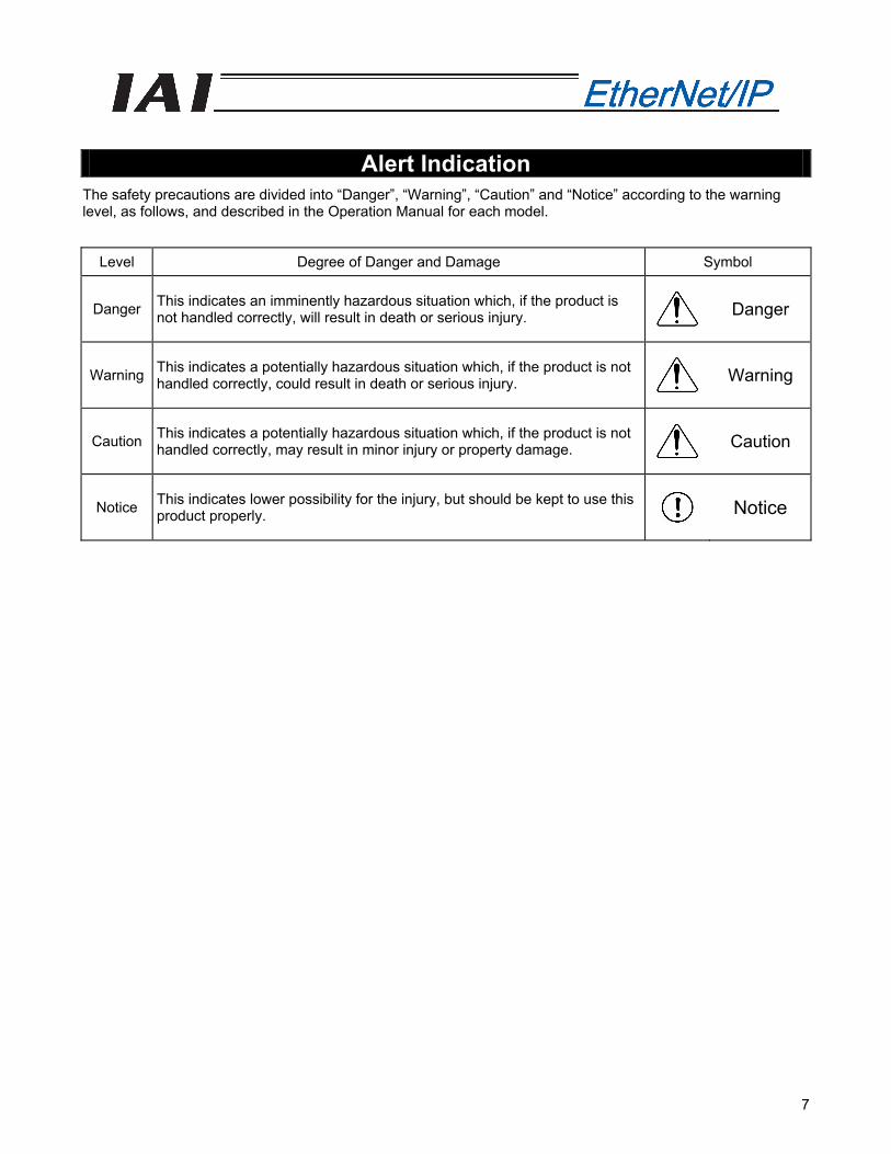
Alert Indication The safety precautions are divided into “Danger”, “Warning”, “Caution” and “Notice” according to the warning level, as follows, and described in the Operation Manual for each model.
Level Degree of Danger and Damage Symbol
Danger This indicates an imminently hazardous situation which, if the product is not handled correctly, will result in death or serious injury.
Danger
Warning This indicates a potentially hazardous situation which, if the product is not handled correctly, could result in death or serious injury.
Warning
Caution This indicates a potentially hazardous situation which, if the product is not handled correctly, may result in minor injury or property damage.
Caution
Notice This indicates lower possibility for the injury, but should be kept to use this product properly. Notice
8
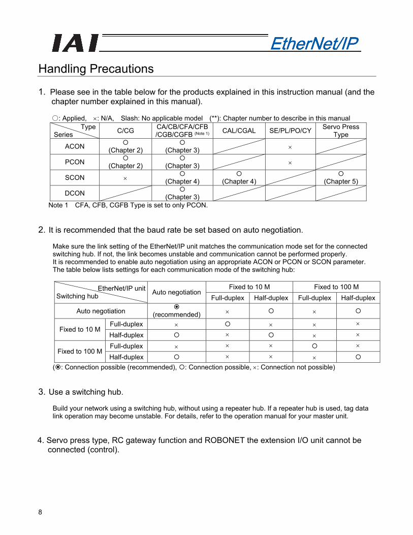
Handling Precautions 1. Please see in the table below for the products explained in this instruction manual (and the
chapter number explained in this manual).
○: Applied, ×: N/A, Slash: No applicable model (**): Chapter number to describe in this manual Type
Series C/CG CA/CB/CFA/CFB/CGB/CGFB (Note 1) CAL/CGAL SE/PL/PO/CY Servo Press
Type
ACON (Chapter 2)
(Chapter 3) ×
PCON (Chapter 2)
(Chapter 3) ×
SCON × (Chapter 4)
(Chapter 4)
(Chapter 5)
DCON (Chapter 3)
Note 1 CFA, CFB, CGFB Type is set to only PCON.
2. It is recommended that the baud rate be set based on auto negotiation.
Make sure the link setting of the EtherNet/IP unit matches the communication mode set for the connected switching hub. If not, the link becomes unstable and communication cannot be performed properly. It is recommended to enable auto negotiation using an appropriate ACON or PCON or SCON parameter. The table below lists settings for each communication mode of the switching hub:
Fixed to 10 M Fixed to 100 M EtherNet/IP unit
Switching hub Auto negotiationFull-duplex Half-duplex Full-duplex Half-duplex
Auto negotiation (recommended) × ×
Full-duplex × × × × Fixed to 10 M
Half-duplex × × ×
Full-duplex × × × × Fixed to 100 M
Half-duplex × × × ( : Connection possible (recommended), : Connection possible, ×: Connection not possible)
3. Use a switching hub.
Build your network using a switching hub, without using a repeater hub. If a repeater hub is used, tag data link operation may become unstable. For details, refer to the operation manual for your master unit.
4. Servo press type, RC gateway function and ROBONET the extension I/O unit cannot be
connected (control).
1. Overview
9
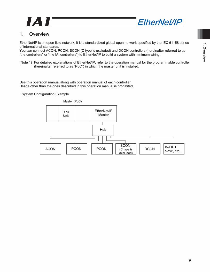
1. Overview EtherNet/IP is an open field network. It is a standardized global open network specified by the IEC 61158 series of international standards. You can connect ACON, PCON, SCON (C type is excluded) and DCON controllers (hereinafter referred to as “the controllers” or “the IAI controllers”) to EtherNet/IP to build a system with minimum wiring. (Note 1) For detailed explanations of EtherNet/IP, refer to the operation manual for the programmable controller
(hereinafter referred to as “PLC”) in which the master unit is installed. Use this operation manual along with operation manual of each controller. Usage other than the ones described in this operation manual is prohibited. System Configuration Example
Master (PLC)
CPU Unit
slave, etc.
Hub
EtherNet/IPMaster
ACON PCON PCON DCON SCON-
(C type is excluded)
IN/OUT slave, etc.
1. O
verv
iew
10
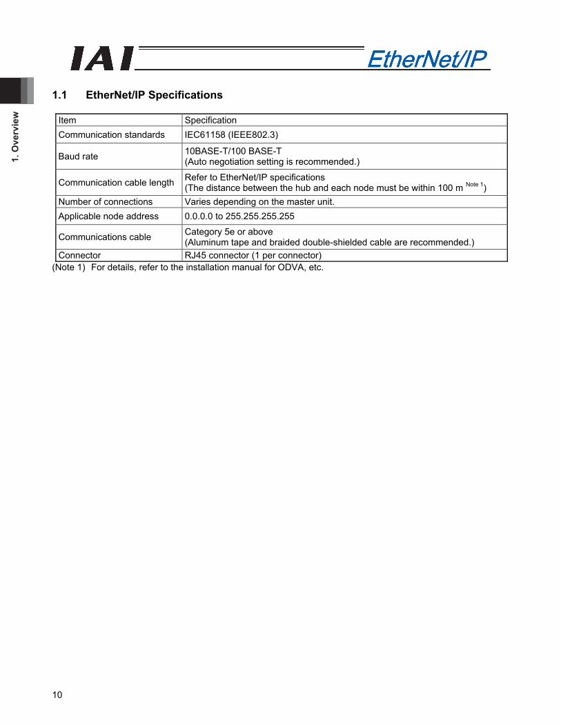
1.1 EtherNet/IP Specifications
Item Specification Communication standards IEC61158 (IEEE802.3)
Baud rate 10BASE-T/100 BASE-T (Auto negotiation setting is recommended.)
Communication cable length Refer to EtherNet/IP specifications (The distance between the hub and each node must be within 100 m Note 1)
Number of connections Varies depending on the master unit. Applicable node address 0.0.0.0 to 255.255.255.255
Communications cable Category 5e or above (Aluminum tape and braided double-shielded cable are recommended.)
Connector RJ45 connector (1 per connector) (Note 1) For details, refer to the installation manual for ODVA, etc.
2. AC
ON
-C/C
G, PC
ON
-C/C
G
11
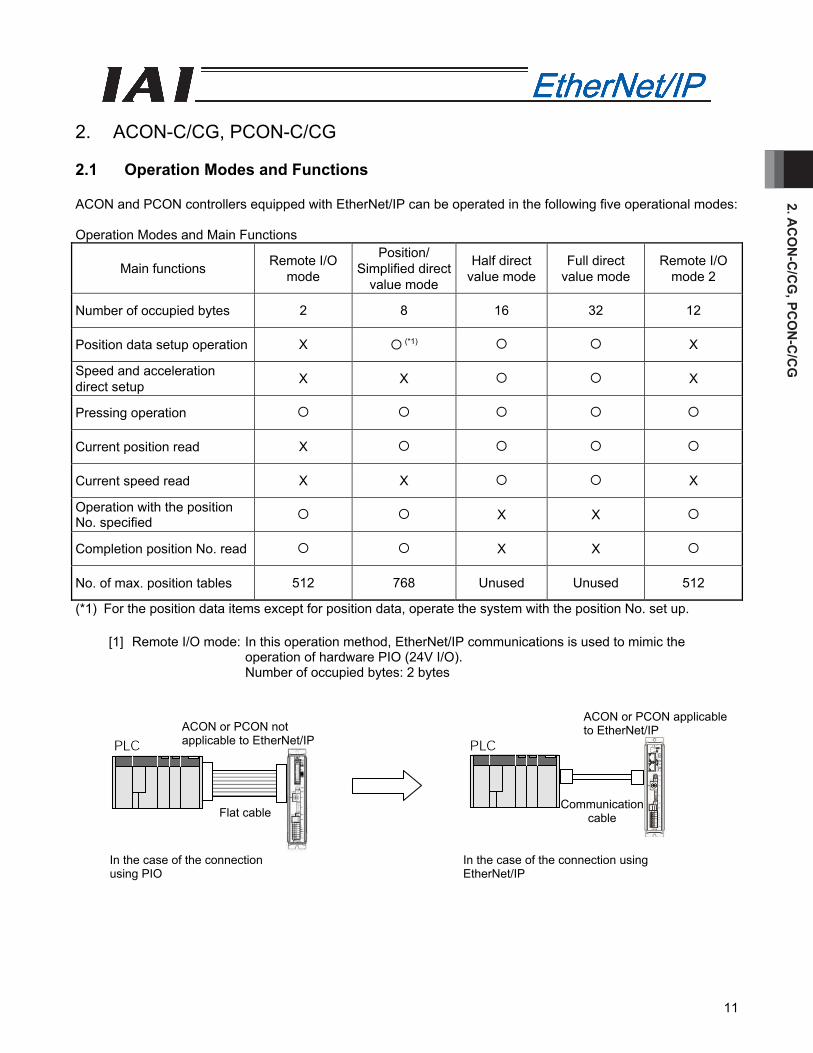
2. ACON-C/CG, PCON-C/CG 2.1 Operation Modes and Functions ACON and PCON controllers equipped with EtherNet/IP can be operated in the following five operational modes: Operation Modes and Main Functions
Main functions Remote I/O mode
Position/ Simplified direct
value mode
Half direct value mode
Full direct value mode
Remote I/O mode 2
Number of occupied bytes 2 8 16 32 12
Position data setup operation X (*1) X
Speed and acceleration direct setup X X X
Pressing operation
Current position read X
Current speed read X X X
Operation with the position No. specified X X
Completion position No. read X X
No. of max. position tables 512 768 Unused Unused 512
(*1) For the position data items except for position data, operate the system with the position No. set up.
[1] Remote I/O mode: In this operation method, EtherNet/IP communications is used to mimic the operation of hardware PIO (24V I/O). Number of occupied bytes: 2 bytes
Communication cable Flat cable
In the case of the connection using EtherNet/IP
In the case of the connection using PIO
ACON or PCON applicable to EtherNet/IP ACON or PCON not
applicable to EtherNet/IP
2. A
CO
N-C
/CG
, PC
ON
-C/C
G
12
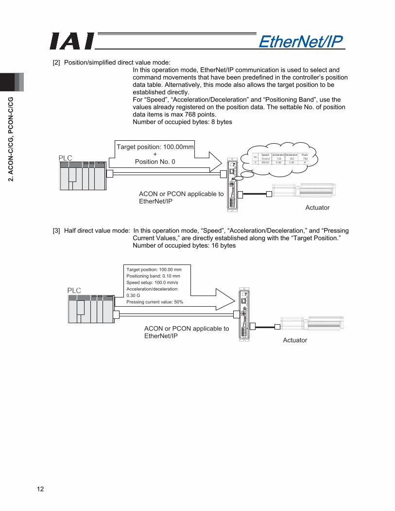
[2] Position/simplified direct value mode:
In this operation mode, EtherNet/IP communication is used to select and command movements that have been predefined in the controller’s position data table. Alternatively, this mode also allows the target position to be established directly. For “Speed”, “Acceleration/Deceleration” and “Positioning Band”, use the values already registered on the position data. The settable No. of position data items is max 768 points. Number of occupied bytes: 8 bytes
Actuator
ACON or PCON applicable to EtherNet/IP
Target position: 100.00mm+
Position No. 0 Speed Acceleration Deceleration Push
[3] Half direct value mode: In this operation mode, “Speed”, “Acceleration/Deceleration,” and “Pressing Current Values,” are directly established along with the “Target Position.” Number of occupied bytes: 16 bytes
Actuator
ACON or PCON applicable to EtherNet/IP
Target position: 100.00 mm Positioning band: 0.10 mm Speed setup: 100.0 mm/s Acceleration/deceleration: 0.30 G Pressing current value: 50%
2. AC
ON
-C/C
G, PC
ON
-C/C
G
13
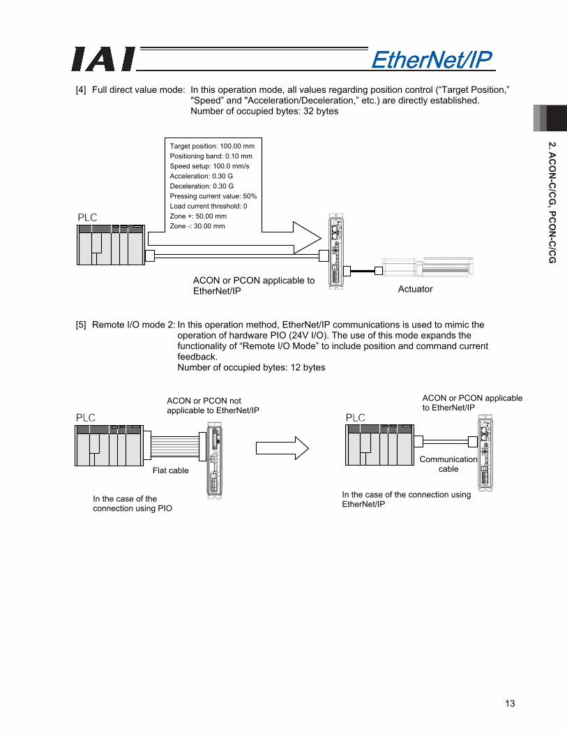
[4] Full direct value mode: In this operation mode, all values regarding position control (“Target Position,”
"Speed” and "Acceleration/Deceleration,” etc.) are directly established. Number of occupied bytes: 32 bytes
[5] Remote I/O mode 2: In this operation method, EtherNet/IP communications is used to mimic the
operation of hardware PIO (24V I/O). The use of this mode expands the functionality of “Remote I/O Mode” to include position and command current feedback. Number of occupied bytes: 12 bytes
Target position: 100.00 mm Positioning band: 0.10 mm Speed setup: 100.0 mm/s Acceleration: 0.30 G Deceleration: 0.30 G Pressing current value: 50% Load current threshold: 0 Zone +: 50.00 mm Zone -: 30.00 mm
Actuator ACON or PCON applicable to EtherNet/IP
ACON or PCON applicable to EtherNet/IP
ACON or PCON not applicable to EtherNet/IP
Communication cable Flat cable
In the case of the connection using EtherNet/IP In the case of the
connection using PIO
2. A
CO
N-C
/CG
, PC
ON
-C/C
G
14
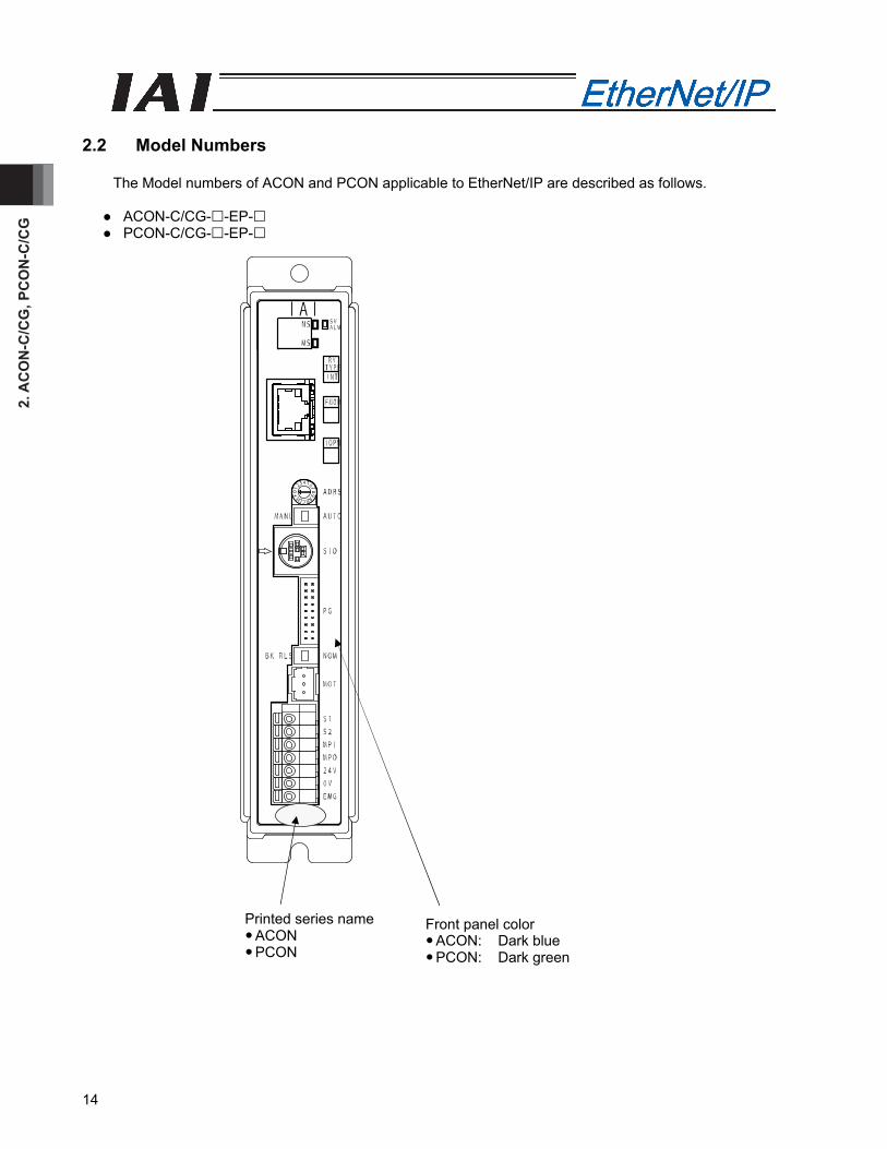
2.2 Model Numbers
The Model numbers of ACON and PCON applicable to EtherNet/IP are described as follows.
● ACON-C/CG- -EP- ● PCON-C/CG- -EP-
Front panel color Printed series name ACON PCON
ACON: Dark blue PCON: Dark green
2. AC
ON
-C/C
G, PC
ON
-C/C
G
15
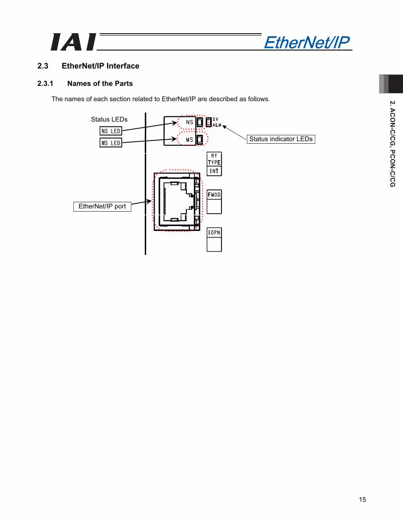
2.3 EtherNet/IP Interface 2.3.1 Names of the Parts
The names of each section related to EtherNet/IP are described as follows.
NS LED
MS LEDStatus indicator LEDs
EtherNet/IP port
Status LEDs
2. A
CO
N-C
/CG
, PC
ON
-C/C
G
16
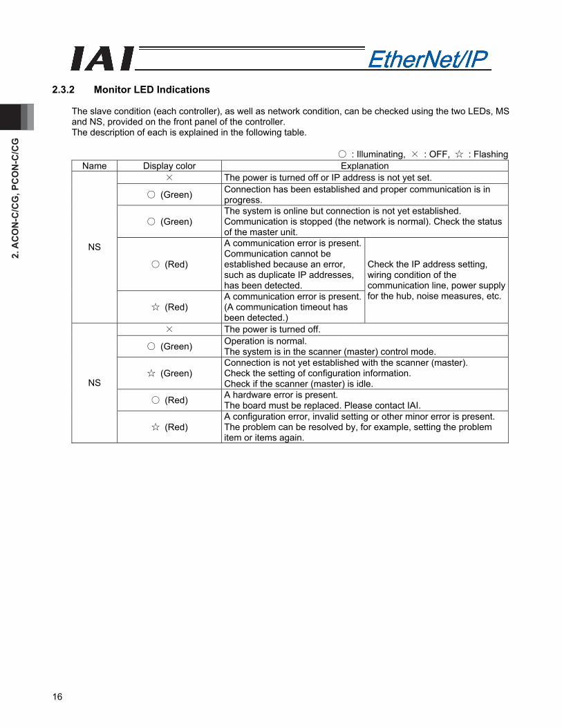
2.3.2 Monitor LED Indications
The slave condition (each controller), as well as network condition, can be checked using the two LEDs, MS and NS, provided on the front panel of the controller. The description of each is explained in the following table.
○ : Illuminating, × : OFF, ☆ : Flashing
Name Display color Explanation × The power is turned off or IP address is not yet set.
○ (Green) Connection has been established and proper communication is in progress.
○ (Green) The system is online but connection is not yet established. Communication is stopped (the network is normal). Check the status of the master unit.
○ (Red)
A communication error is present. Communication cannot be established because an error, such as duplicate IP addresses, has been detected.
NS
☆ (Red) A communication error is present. (A communication timeout has been detected.)
Check the IP address setting, wiring condition of the communication line, power supply for the hub, noise measures, etc.
× The power is turned off.
○ (Green) Operation is normal. The system is in the scanner (master) control mode.
☆ (Green) Connection is not yet established with the scanner (master). Check the setting of configuration information. Check if the scanner (master) is idle.
○ (Red) A hardware error is present. The board must be replaced. Please contact IAI.
NS
☆ (Red) A configuration error, invalid setting or other minor error is present. The problem can be resolved by, for example, setting the problem item or items again.
2. AC
ON
-C/C
G, PC
ON
-C/C
G
17
8
1
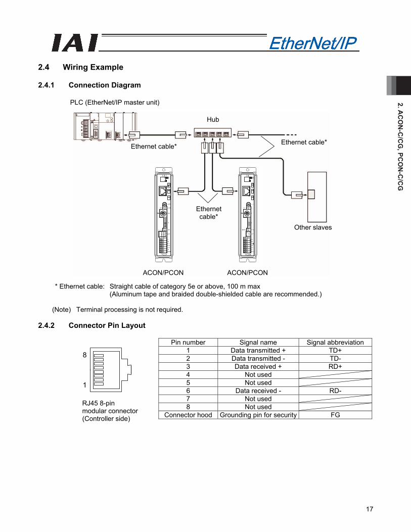
2.4 Wiring Example 2.4.1 Connection Diagram
* Ethernet cable: Straight cable of category 5e or above, 100 m max (Aluminum tape and braided double-shielded cable are recommended.)
(Note) Terminal processing is not required.
2.4.2 Connector Pin Layout
Pin number Signal name Signal abbreviation 1 Data transmitted + TD+ 2 Data transmitted - TD- 3 Data received + RD+ 4 Not used 5 Not used 6 Data received - RD- 7 Not used 8 Not used
Connector hood Grounding pin for security FG
RJ45 8-pin modular connector (Controller side)
PLC (EtherNet/IP master unit)
Ethernet cable*
Ethernet cable* Ethernet cable*
Other slaves
ACON/PCONACON/PCON
Hub
2. A
CO
N-C
/CG
, PC
ON
-C/C
G
18
2.5 Setting
Using the teaching tool, set controller parameters. Set the mode toggle switch on the front panel of the controller to “MANU” side. The versions of teaching tool compatible with EtherNet/IP are as follows: • RC PC-compatible software: V8.02.00.00 or later • CON-T/TG: V1.10 or later • CON-PT/PD/PG: V1.20 or later • RCM-E/P: V2.20 (Planned)
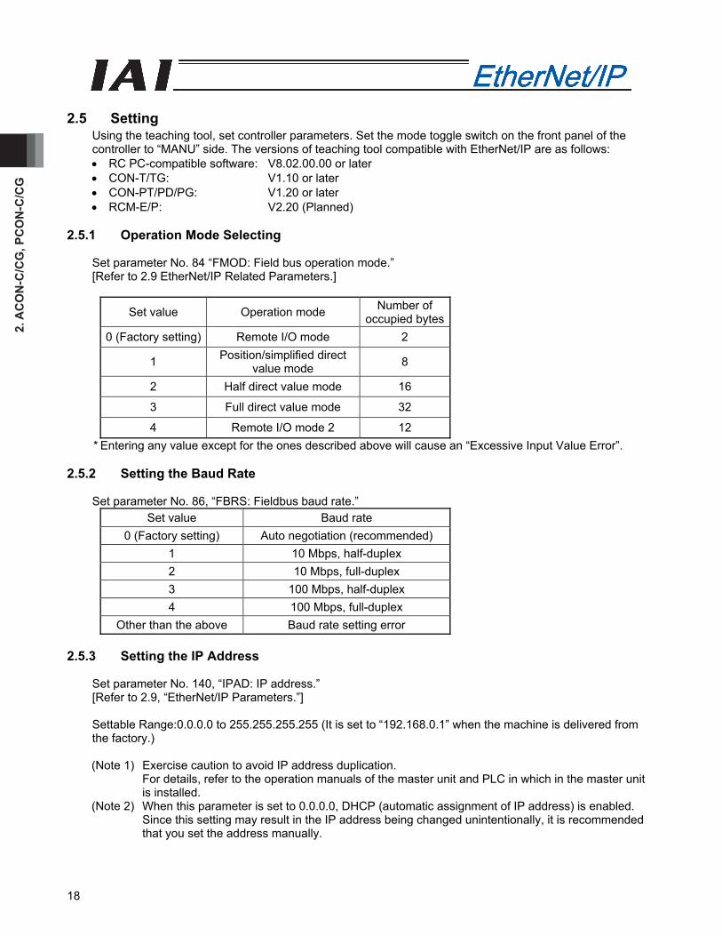
2.5.1 Operation Mode Selecting
Set parameter No. 84 “FMOD: Field bus operation mode.” [Refer to 2.9 EtherNet/IP Related Parameters.]
Set value Operation mode Number of occupied bytes
0 (Factory setting) Remote I/O mode 2
1 Position/simplified direct value mode 8
2 Half direct value mode 16
3 Full direct value mode 32
4 Remote I/O mode 2 12 * Entering any value except for the ones described above will cause an “Excessive Input Value Error”.
2.5.2 Setting the Baud Rate
Set parameter No. 86, “FBRS: Fieldbus baud rate.” Set value Baud rate
0 (Factory setting) Auto negotiation (recommended) 1 10 Mbps, half-duplex 2 10 Mbps, full-duplex 3 100 Mbps, half-duplex 4 100 Mbps, full-duplex
Other than the above Baud rate setting error 2.5.3 Setting the IP Address
Set parameter No. 140, “IPAD: IP address.” [Refer to 2.9, “EtherNet/IP Parameters.”] Settable Range:0.0.0.0 to 255.255.255.255 (It is set to “192.168.0.1” when the machine is delivered from the factory.) (Note 1) Exercise caution to avoid IP address duplication.
For details, refer to the operation manuals of the master unit and PLC in which in the master unit is installed.
(Note 2) When this parameter is set to 0.0.0.0, DHCP (automatic assignment of IP address) is enabled. Since this setting may result in the IP address being changed unintentionally, it is recommended that you set the address manually.

2. AC
ON
-C/C
G, PC
ON
-C/C
G
19
2.5.4 Setting the Subnet Mask
Set parameter No. 141, “SNMK: Subnet mask.” Set the same value you have set in the master unit and other slaves (on the same network). [Refer to 2.9, “EtherNet/IP Parameters.”] Settable range: 0.0.0.0 to 255.255.255.255 (The factory setting is 255.255.255.0.)
2.5.5 Setting the Default Gateway
If necessary, set parameter No. 142, “DFGW: Default gateway.” [Refer to 2.9, “EtherNet/IP Parameters.”] Settable range: 0.0.0.0 to 255.255.255.255 (The factory setting is 0.0.0.0.)
(Note) After the parameter setting, turn on the power to the controller again and return the mode toggle switch on the front of the controller to “AUTO” side. When the switch is set to “MANU”, the operation using PLC is not available.
2. A
CO
N-C
/CG
, PC
ON
-C/C
G
20
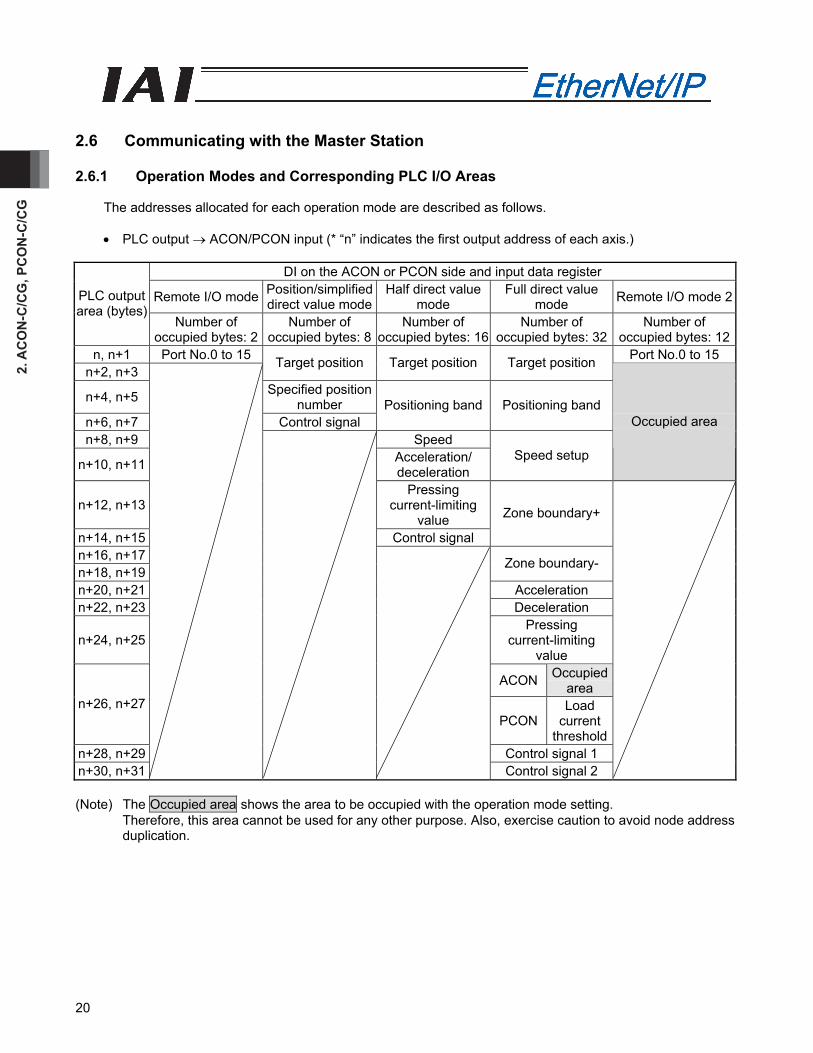
2.6 Communicating with the Master Station 2.6.1 Operation Modes and Corresponding PLC I/O Areas
The addresses allocated for each operation mode are described as follows.
• PLC output → ACON/PCON input (* “n” indicates the first output address of each axis.)
DI on the ACON or PCON side and input data register
Remote I/O mode Position/simplified direct value mode
Half direct value mode
Full direct value mode Remote I/O mode 2PLC output
area (bytes) Number of
occupied bytes: 2 Number of
occupied bytes: 8Number of
occupied bytes: 16Number of
occupied bytes: 32 Number of
occupied bytes: 12n, n+1 Port No.0 to 15 Port No.0 to 15
n+2, n+3 Target position Target position Target position
n+4, n+5 Specified position number
n+6, n+7 Control signal Positioning band Positioning band
n+8, n+9 Speed
n+10, n+11 Acceleration/ deceleration
Speed setup
Occupied area
n+12, n+13 Pressing
current-limiting value
n+14, n+15 Control signal
Zone boundary+
n+16, n+17 n+18, n+19
Zone boundary-
n+20, n+21 Acceleration n+22, n+23 Deceleration
n+24, n+25 Pressing
current-limiting value
ACON Occupied area
n+26, n+27 PCON
Load current
threshold n+28, n+29 Control signal 1 n+30, n+31
Control signal 2
(Note) The Occupied area shows the area to be occupied with the operation mode setting.
Therefore, this area cannot be used for any other purpose. Also, exercise caution to avoid node address duplication.
2. AC
ON
-C/C
G, PC
ON
-C/C
G
21
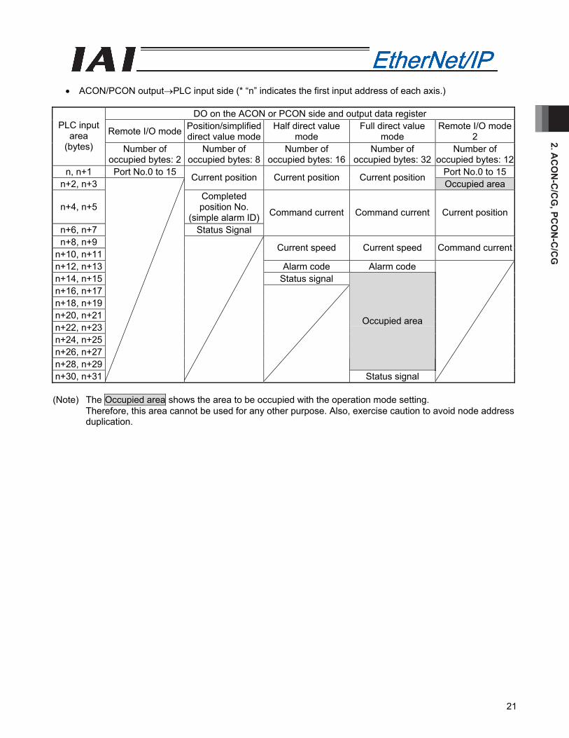
• ACON/PCON output→PLC input side (* “n” indicates the first input address of each axis.)
DO on the ACON or PCON side and output data register
Remote I/O mode Position/simplified direct value mode
Half direct value mode
Full direct value mode
Remote I/O mode2
PLC input area
(bytes) Number of occupied bytes: 2
Number of occupied bytes: 8
Number of occupied bytes: 16
Number of occupied bytes: 32
Number of occupied bytes: 12
n, n+1 Port No.0 to 15 Port No.0 to 15n+2, n+3
Current position Current position Current position Occupied area
n+4, n+5 Completed position No.
(simple alarm ID)n+6, n+7 Status Signal
Command current Command current Current position
n+8, n+9 n+10, n+11
Current speed Current speed Command current
n+12, n+13 Alarm code Alarm code n+14, n+15 Status signal n+16, n+17 n+18, n+19 n+20, n+21 n+22, n+23 n+24, n+25 n+26, n+27 n+28, n+29
Occupied area
n+30, n+31
Status signal
(Note) The Occupied area shows the area to be occupied with the operation mode setting.
Therefore, this area cannot be used for any other purpose. Also, exercise caution to avoid node address duplication.
2. A
CO
N-C
/CG
, PC
ON
-C/C
G
22
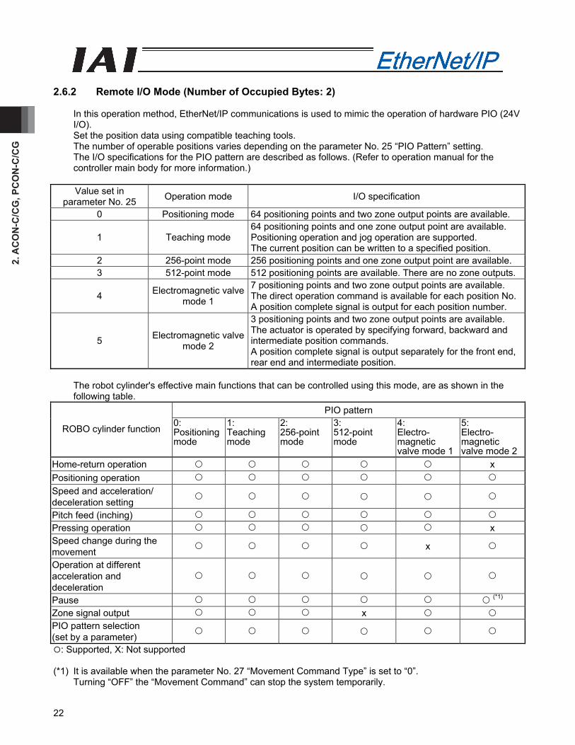
2.6.2 Remote I/O Mode (Number of Occupied Bytes: 2)
In this operation method, EtherNet/IP communications is used to mimic the operation of hardware PIO (24V I/O). Set the position data using compatible teaching tools. The number of operable positions varies depending on the parameter No. 25 “PIO Pattern” setting. The I/O specifications for the PIO pattern are described as follows. (Refer to operation manual for the controller main body for more information.)
Value set in
parameter No. 25 Operation mode I/O specification
0 Positioning mode 64 positioning points and two zone output points are available.
1 Teaching mode 64 positioning points and one zone output point are available. Positioning operation and jog operation are supported. The current position can be written to a specified position.
2 256-point mode 256 positioning points and one zone output point are available. 3 512-point mode 512 positioning points are available. There are no zone outputs.
4 Electromagnetic valve mode 1
7 positioning points and two zone output points are available. The direct operation command is available for each position No.A position complete signal is output for each position number.
5 Electromagnetic valve mode 2
3 positioning points and two zone output points are available. The actuator is operated by specifying forward, backward and intermediate position commands. A position complete signal is output separately for the front end, rear end and intermediate position.
The robot cylinder's effective main functions that can be controlled using this mode, are as shown in the following table.
PIO pattern
ROBO cylinder function 0: Positioning mode
1: Teaching mode
2: 256-point mode
3: 512-point mode
4: Electro- magnetic valve mode 1
5: Electro- magnetic valve mode 2
Home-return operation x Positioning operation Speed and acceleration/ deceleration setting
Pitch feed (inching) Pressing operation x Speed change during the movement x
Operation at different acceleration and deceleration
Pause (*1) Zone signal output x PIO pattern selection (set by a parameter)
: Supported, X: Not supported (*1) It is available when the parameter No. 27 “Movement Command Type” is set to “0”.
Turning “OFF” the “Movement Command” can stop the system temporarily.
2. AC
ON
-C/C
G, PC
ON
-C/C
G
23
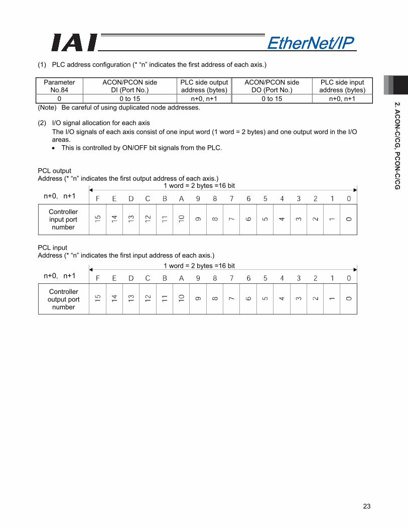
(1) PLC address configuration (* “n” indicates the first address of each axis.)
Parameter No.84
ACON/PCON side DI (Port No.)
PLC side output address (bytes)
ACON/PCON side DO (Port No.)
PLC side input address (bytes)
0 0 to 15 n+0, n+1 0 to 15 n+0, n+1 (Note) Be careful of using duplicated node addresses. (2) I/O signal allocation for each axis
The I/O signals of each axis consist of one input word (1 word = 2 bytes) and one output word in the I/O areas. • This is controlled by ON/OFF bit signals from the PLC.
PCL output Address (* “n” indicates the first output address of each axis.) PCL input Address (* “n” indicates the first input address of each axis.)
Controller input port number
1 word = 2 bytes =16 bitn+0, n+1
Controller output port
number
1 word = 2 bytes =16 bitn+0, n+1

2. A
CO
N-C
/CG
, PC
ON
-C/C
G
24
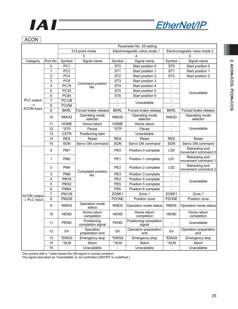
(3) I/O signal assignment
The controller's I/O port signal varies depending on the parameter No. 25 setting. (Refer to operation manual for the controller main body for more information.)
ACON Parameter No. 25 setting
Positioning mode Teaching mode 256-point mode 0 1 2
Category Port No. Symbol Signal name Symbol Signal name Symbol Signal name 0 PC1 PC1 PC1 1 PC2 PC2 PC2 2 PC4 PC4 PC4 3 PC8 PC8 PC8 4 PC16 PC16 PC16 5 PC32
Command position No.
PC32
Command position No.
PC32
6 - MODE Teaching mode command PC64
7 - JISL Jog/inching selector PC128
Command position No.
8 -
Unavailable
JOG+ +Jog - Unavailable 9 BKRL Forced brake release JOG- -Jog BKRL Forced brake release
10 RMOD Operating mode selector RMOD Operating mode selector RMOD Operating mode
selector 11 HOME Home return HOME Home return HOME Home return 12 *STP Pause *STP Pause *STP Pause
13 CSTR Positioning start CSTR/PWRT
Positioning start/position data import command CSTR Positioning start
14 RES Reset RES Reset RES Reset
PLC output →
ACON input
15 SON Servo ON command SON Servo ON command SON Servo ON command0 PM1 PM1 PM1 1 PM2 PM2 PM2 2 PM4 PM4 PM4 3 PM8 PM8 PM8 4 PM16 PM16 PM16 5 PM32
Completed position No.
PM32
Completed position No.
PM32 6 MOVE Moving signal MOVE Moving signal PM64 7 ZONE1 Zone 1 MODES Teaching mode signal PM128
Completed position No.
8 PZONE Position zone PZONE Position zone PZONE Position zone
9 RMDS Operation mode status RMDS Operation mode status RMDS Operation mode
status
10 HEND Home return completion HEND Home return completion HEND Home return
completion
11 PEND Positioning completion signal
PEND/WEND
Positioning completion signal/
position-data read complete
PEND Positioning completion signal
12 SV Operation preparation end SV Operation preparation
end SV Operation preparation end
13 *EMGS Emergency stop *EMGS Emergency stop *EMGS Emergency stop 14 *ALM Alarm *ALM Alarm *ALM Alarm
ACON output →
PLC input
15 - Unavailable - Unavailable - Unavailable The symbol with a * mark shows the ON signal in normal condition. The signal described as “Unavailable” is not controlled. (ON/OFF is undefined.)
2. AC
ON
-C/C
G, PC
ON
-C/C
G
25
ACON Parameter No. 25 setting
512-point mode Electromagnetic valve mode 1 Electromagnetic valve mode 2 3 4 5
Category Port No. Symbol Signal name Symbol Signal name Symbol Signal name 0 PC1 ST0 Start position 0 ST0 Start position 0 1 PC2 ST1 Start position 1 ST1 Start position 1 2 PC4 ST2 Start position 2 ST2 Start position 2 3 PC8 ST3 Start position 3 - 4 PC16 ST4 Start position 4 - 5 PC32 ST5 Start position 5 - 6 PC64 ST6 Start position 6 - 7 PC128 - - 8 PC256
Command position No.
- Unavailable
-
Unavailable
9 BKRL Forced brake release BKRL Forced brake release BKRL Forced brake release
10 RMOD Operating mode selector RMOD Operating mode
selector RMOD Operating mode selector
11 HOME Home return HOME Home return - 12 *STP Pause *STP Pause - 13 CSTR Positioning start - Unavailable -
Unavailable
14 RES Reset RES Reset RES Reset
PLC output →
ACON input
15 SON Servo ON command SON Servo ON command SON Servo ON command
0 PM1 PE0 Position 0 complete LS0 Retracting end movement command 0
1 PM2 PE1 Position 1 complete LS1 Retracting end movement command 1
2 PM4 PE2 Position 2 complete LS2 Retracting end movement command 2
3 PM8 PE3 Position 3 complete - 4 PM16 PE4 Position 4 complete - 5 PM32 PE5 Position 5 complete - 6 PM64 PE6 Position 6 complete -
Unavailable
7 PM128 ZONE1 Zone 1 ZONE1 Zone 1 8 PM256
Completed position No.
PZONE Position zone PZONE Position zone
9 RMDS Operation mode status RMDS Operation mode status RMDS Operation mode status
10 HEND Home return completion HEND Home return
completion HEND Home return completion
11 PEND Positioning completion signal PEND Positioning completion
signal - Unavailable
12 SV Operation preparation end SV Operation preparation
end SV Operation preparation end
13 *EMGS Emergency stop *EMGS Emergency stop *EMGS Emergency stop 14 *ALM Alarm *ALM Alarm *ALM Alarm
ACON output → PLC input
15 - Unavailable - Unavailable - Unavailable The symbol with a * mark shows the ON signal in normal condition. The signal described as “Unavailable” is not controlled.(ON/OFF is undefined.)
2. A
CO
N-C
/CG
, PC
ON
-C/C
G
26
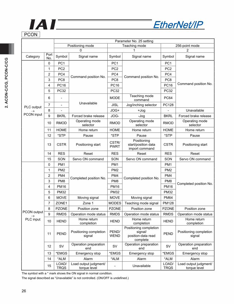
PCON Parameter No. 25 setting
Positioning mode Teaching mode 256-point mode 0 1 2
Category Port No. Symbol Signal name Symbol Signal name Symbol Signal name
0 PC1 PC1 PC1 1 PC2 PC2 PC2 2 PC4 PC4 PC4 3 PC8 PC8 PC8 4 PC16 PC16 PC16 5 PC32
Command position No.
PC32
Command position No.
PC32
6 - MODE Teaching mode command PC64
7 - JISL Jog/inching selector PC128
Command position No.
8 -
Unavailable
JOG+ +Jog - Unavailable 9 BKRL Forced brake release JOG- -Jog BKRL Forced brake release
10 RMOD Operating mode selector RMOD Operating mode
selector RMOD Operating mode selector
11 HOME Home return HOME Home return HOME Home return 12 *STP Pause *STP Pause *STP Pause
13 CSTR Positioning start CSTR/PWRT
Positioning start/position data import command
CSTR Positioning start
14 RES Reset RES Reset RES Reset
PLC output →
PCON input
15 SON Servo ON command SON Servo ON command SON Servo ON command 0 PM1 PM1 PM1 1 PM2 PM2 PM2 2 PM4 PM4 PM4 3 PM8 PM8 PM8 4 PM16 PM16 PM16 5 PM32
Completed position No.
PM32
Completed position No.
PM32 6 MOVE Moving signal MOVE Moving signal PM64 7 ZONE1 Zone 1 MODES Teaching mode signal PM128
Completed position No.
8 PZONE Position zone PZONE Position zone PZONE Position zone 9 RMDS Operation mode status RMDS Operation mode status RMDS Operation mode status
10 HEND Home return completion HEND Home return
completion HEND Home return completion
11 PEND Positioning completion signal
PEND/WEND
Positioning completion signal/
position-data read complete
PEND Positioning completion signal
12 SV Operation preparation end SV Operation preparation
end SV Operation preparation end
13 *EMGS Emergency stop *EMGS Emergency stop *EMGS Emergency stop 14 *ALM Alarm *ALM Alarm *ALM Alarm
PCON output →
PLC input
15 LOAD/ TRQS
Load output judgment/torque level - Unavailable LOAD/
TRQS Load output judgment/
torque level The symbol with a * mark shows the ON signal in normal condition. The signal described as “Unavailable” is not controlled. (ON/OFF is undefined.)
2. AC
ON
-C/C
G, PC
ON
-C/C
G
27
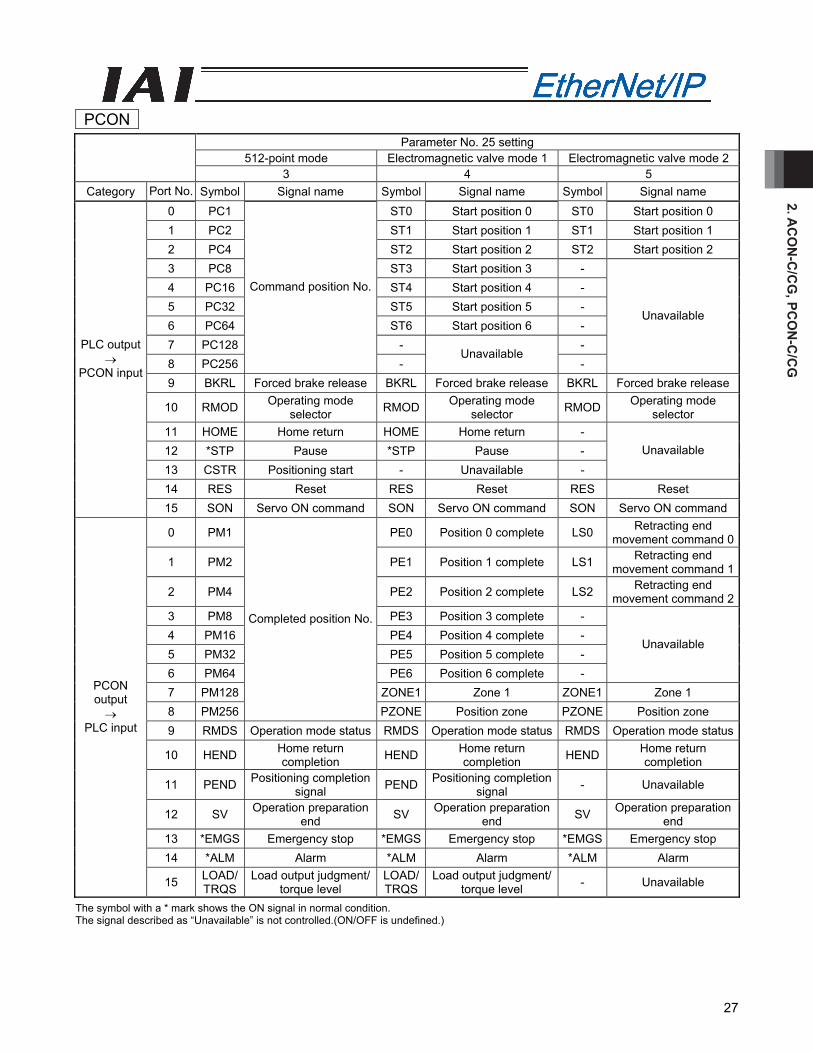
PCON Parameter No. 25 setting
512-point mode Electromagnetic valve mode 1 Electromagnetic valve mode 2 3 4 5
Category Port No. Symbol Signal name Symbol Signal name Symbol Signal name 0 PC1 ST0 Start position 0 ST0 Start position 0 1 PC2 ST1 Start position 1 ST1 Start position 1 2 PC4 ST2 Start position 2 ST2 Start position 2 3 PC8 ST3 Start position 3 - 4 PC16 ST4 Start position 4 - 5 PC32 ST5 Start position 5 - 6 PC64 ST6 Start position 6 - 7 PC128 - - 8 PC256
Command position No.
- Unavailable
-
Unavailable
9 BKRL Forced brake release BKRL Forced brake release BKRL Forced brake release
10 RMOD Operating mode selector RMOD Operating mode
selector RMOD Operating mode selector
11 HOME Home return HOME Home return - 12 *STP Pause *STP Pause - 13 CSTR Positioning start - Unavailable -
Unavailable
14 RES Reset RES Reset RES Reset
PLC output →
PCON input
15 SON Servo ON command SON Servo ON command SON Servo ON command
0 PM1 PE0 Position 0 complete LS0 Retracting end movement command 0
1 PM2 PE1 Position 1 complete LS1 Retracting end movement command 1
2 PM4 PE2 Position 2 complete LS2 Retracting end movement command 2
3 PM8 PE3 Position 3 complete - 4 PM16 PE4 Position 4 complete - 5 PM32 PE5 Position 5 complete - 6 PM64 PE6 Position 6 complete -
Unavailable
7 PM128 ZONE1 Zone 1 ZONE1 Zone 1 8 PM256
Completed position No.
PZONE Position zone PZONE Position zone 9 RMDS Operation mode status RMDS Operation mode status RMDS Operation mode status
10 HEND Home return completion HEND Home return
completion HEND Home return completion
11 PEND Positioning completion signal PEND Positioning completion
signal - Unavailable
12 SV Operation preparation end SV Operation preparation
end SV Operation preparation end
13 *EMGS Emergency stop *EMGS Emergency stop *EMGS Emergency stop 14 *ALM Alarm *ALM Alarm *ALM Alarm
PCON output →
PLC input
15 LOAD/ TRQS
Load output judgment/torque level
LOAD/TRQS
Load output judgment/torque level - Unavailable
The symbol with a * mark shows the ON signal in normal condition. The signal described as “Unavailable” is not controlled.(ON/OFF is undefined.)
2. A
CO
N-C
/CG
, PC
ON
-C/C
G
28
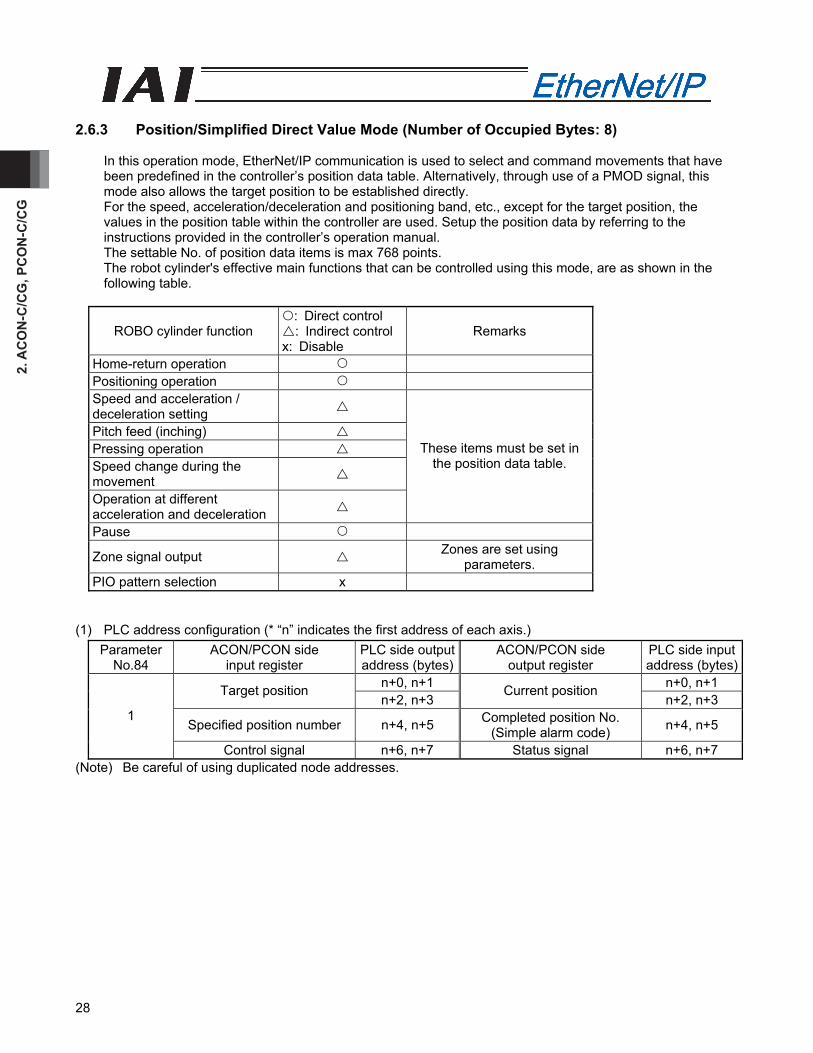
2.6.3 Position/Simplified Direct Value Mode (Number of Occupied Bytes: 8)
In this operation mode, EtherNet/IP communication is used to select and command movements that have been predefined in the controller’s position data table. Alternatively, through use of a PMOD signal, this mode also allows the target position to be established directly. For the speed, acceleration/deceleration and positioning band, etc., except for the target position, the values in the position table within the controller are used. Setup the position data by referring to the instructions provided in the controller’s operation manual. The settable No. of position data items is max 768 points. The robot cylinder's effective main functions that can be controlled using this mode, are as shown in the following table.
ROBO cylinder function : Direct control : Indirect control
x: Disable Remarks
Home-return operation Positioning operation Speed and acceleration / deceleration setting
Pitch feed (inching) Pressing operation Speed change during the movement
Operation at different acceleration and deceleration
These items must be set in the position data table.
Pause
Zone signal output Zones are set using parameters.
PIO pattern selection x
(1) PLC address configuration (* “n” indicates the first address of each axis.)
Parameter No.84
ACON/PCON side input register
PLC side output address (bytes)
ACON/PCON side output register
PLC side input address (bytes)
n+0, n+1 n+0, n+1 Target position n+2, n+3
Current position n+2, n+3
Specified position number n+4, n+5 Completed position No. (Simple alarm code) n+4, n+5
1
Control signal n+6, n+7 Status signal n+6, n+7 (Note) Be careful of using duplicated node addresses.
2. AC
ON
-C/C
G, PC
ON
-C/C
G
29
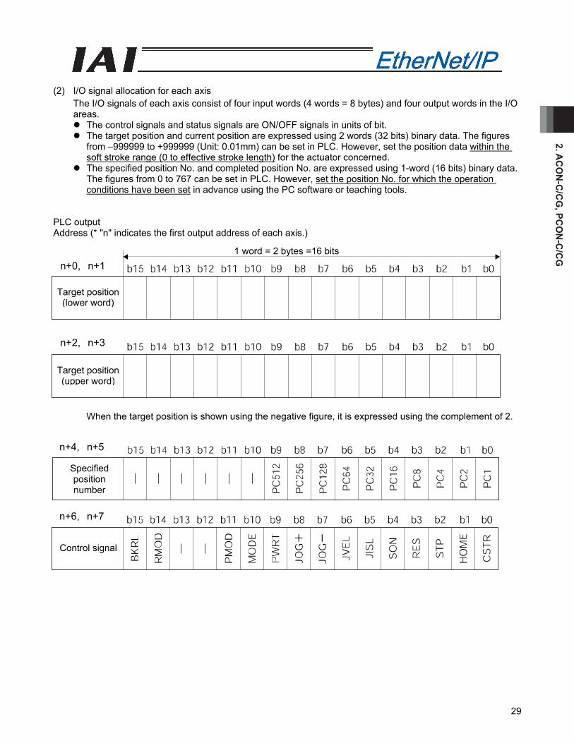
(2) I/O signal allocation for each axis
The I/O signals of each axis consist of four input words (4 words = 8 bytes) and four output words in the I/O areas.
The control signals and status signals are ON/OFF signals in units of bit. The target position and current position are expressed using 2 words (32 bits) binary data. The figures
from –999999 to +999999 (Unit: 0.01mm) can be set in PLC. However, set the position data within the soft stroke range (0 to effective stroke length) for the actuator concerned.
The specified position No. and completed position No. are expressed using 1-word (16 bits) binary data. The figures from 0 to 767 can be set in PLC. However, set the position No. for which the operation conditions have been set in advance using the PC software or teaching tools.
PLC output Address (* "n" indicates the first output address of each axis.)
When the target position is shown using the negative figure, it is expressed using the complement of 2.
1 word = 2 bytes =16 bits
Target position (lower word)
Target position (upper word)
n+2, n+3
n+0, n+1
Specified position number
Control signal
n+4, n+5
n+6, n+7
2. A
CO
N-C
/CG
, PC
ON
-C/C
G
30
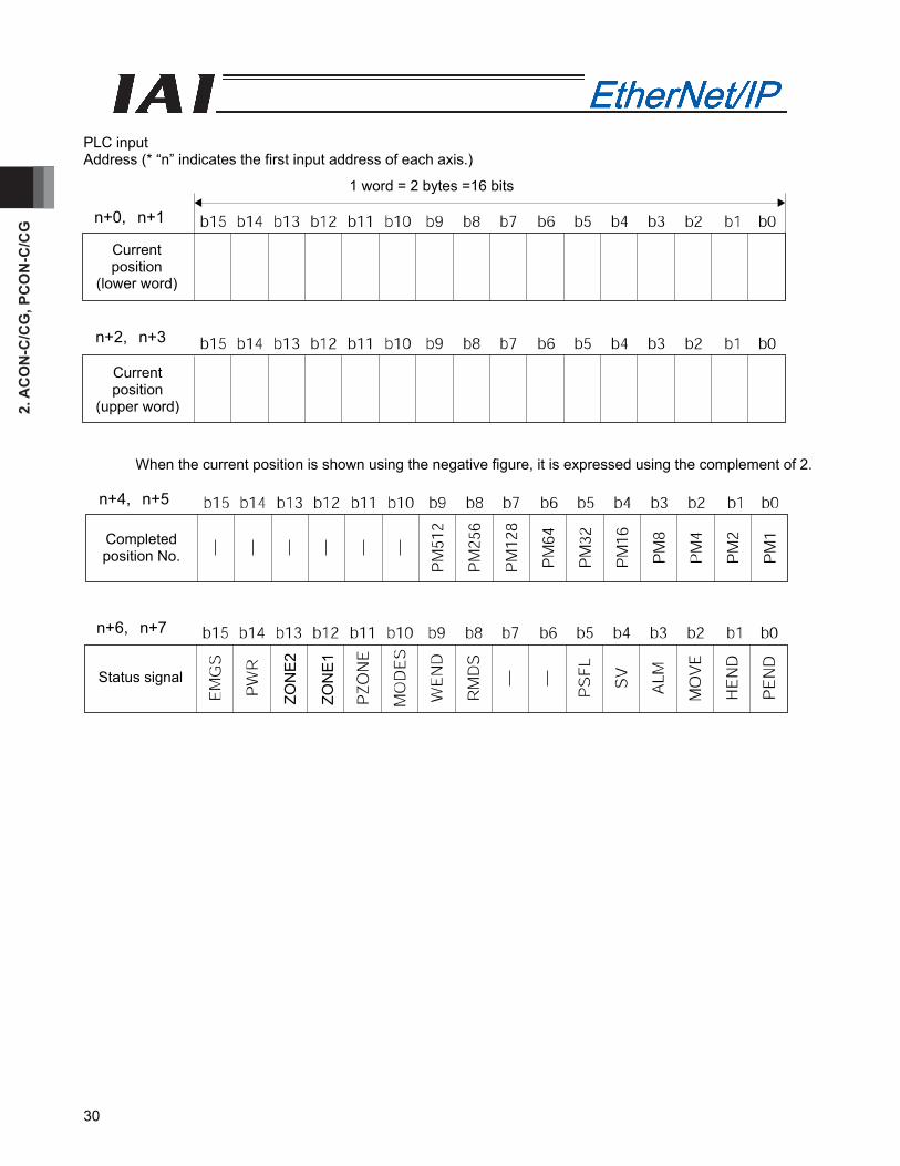
PLC input Address (* “n” indicates the first input address of each axis.)
When the current position is shown using the negative figure, it is expressed using the complement of 2.
1 word = 2 bytes =16 bits
Current position
(lower word)
Current position
(upper word)
n+0, n+1
n+2, n+3
Completed position No.
Status signal
n+4, n+5
n+6, n+7
ZON
E2
ZON
E1
2. AC
ON
-C/C
G, PC
ON
-C/C
G
31
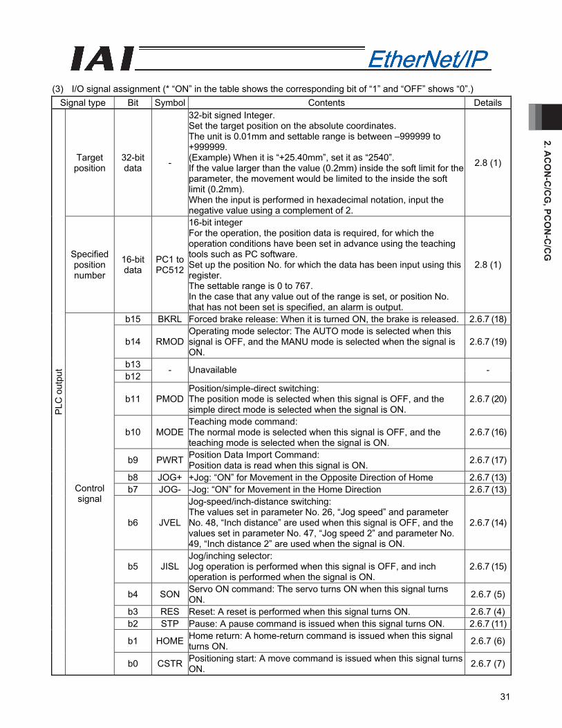
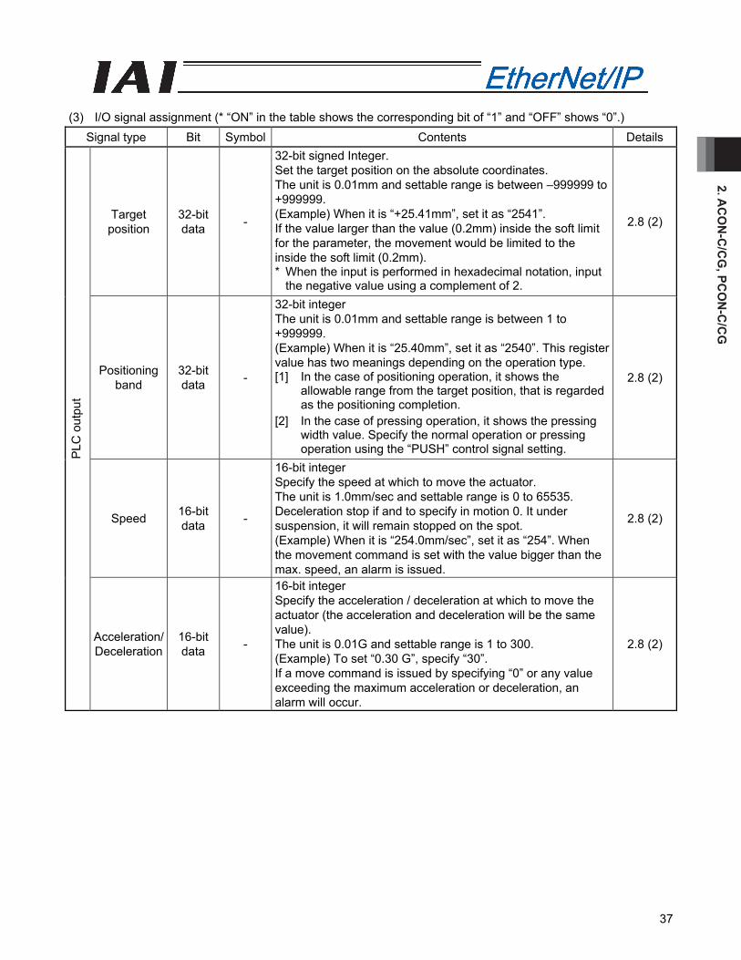
(3) I/O signal assignment (* “ON” in the table shows the corresponding bit of “1” and “OFF” shows “0”.)
Signal type Bit Symbol Contents Details
Target position
32-bit data -
32-bit signed Integer. Set the target position on the absolute coordinates. The unit is 0.01mm and settable range is between –999999 to +999999. (Example) When it is “+25.40mm”, set it as “2540”. If the value larger than the value (0.2mm) inside the soft limit for the parameter, the movement would be limited to the inside the soft limit (0.2mm). When the input is performed in hexadecimal notation, input the negative value using a complement of 2.
2.8 (1)
Specified position number
16-bit data
PC1 to PC512
16-bit integer For the operation, the position data is required, for which the operation conditions have been set in advance using the teaching tools such as PC software. Set up the position No. for which the data has been input using this register. The settable range is 0 to 767. In the case that any value out of the range is set, or position No. that has not been set is specified, an alarm is output.
2.8 (1)
b15 BKRL Forced brake release: When it is turned ON, the brake is released. 2.6.7 (18)
b14 RMOD Operating mode selector: The AUTO mode is selected when this signal is OFF, and the MANU mode is selected when the signal is ON.
2.6.7 (19)
b13 b12
- Unavailable -
b11 PMOD Position/simple-direct switching: The position mode is selected when this signal is OFF, and the simple direct mode is selected when the signal is ON.
2.6.7 (20)
b10 MODE Teaching mode command: The normal mode is selected when this signal is OFF, and the teaching mode is selected when the signal is ON.
2.6.7 (16)
b9 PWRT Position Data Import Command: Position data is read when this signal is ON. 2.6.7 (17)
b8 JOG+ +Jog: “ON” for Movement in the Opposite Direction of Home 2.6.7 (13)b7 JOG- -Jog: “ON” for Movement in the Home Direction 2.6.7 (13)
b6 JVEL
Jog-speed/inch-distance switching: The values set in parameter No. 26, “Jog speed” and parameter No. 48, “Inch distance” are used when this signal is OFF, and the values set in parameter No. 47, “Jog speed 2” and parameter No. 49, “Inch distance 2” are used when the signal is ON.
2.6.7 (14)
b5 JISL Jog/inching selector: Jog operation is performed when this signal is OFF, and inch operation is performed when the signal is ON.
2.6.7 (15)
b4 SON Servo ON command: The servo turns ON when this signal turns ON. 2.6.7 (5)
b3 RES Reset: A reset is performed when this signal turns ON. 2.6.7 (4)b2 STP Pause: A pause command is issued when this signal turns ON. 2.6.7 (11)
b1 HOME Home return: A home-return command is issued when this signal turns ON. 2.6.7 (6)
PLC
out
put
Control signal
b0 CSTR Positioning start: A move command is issued when this signal turns ON. 2.6.7 (7)
2. A
CO
N-C
/CG
, PC
ON
-C/C
G
32
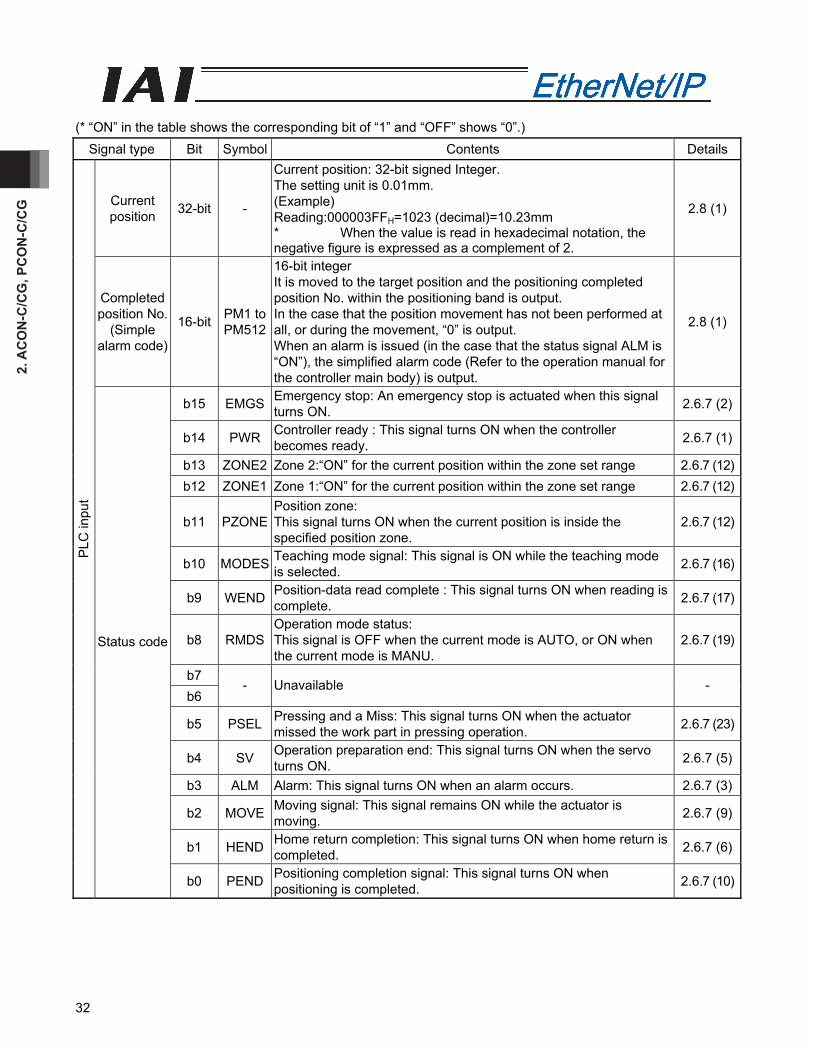
(* “ON” in the table shows the corresponding bit of “1” and “OFF” shows “0”.)
Signal type Bit Symbol Contents Details
Current position 32-bit -
Current position: 32-bit signed Integer. The setting unit is 0.01mm. (Example) Reading:000003FFH=1023 (decimal)=10.23mm * When the value is read in hexadecimal notation, the negative figure is expressed as a complement of 2.
2.8 (1)
Completed position No.
(Simple alarm code)
16-bit PM1 to PM512
16-bit integer It is moved to the target position and the positioning completed position No. within the positioning band is output. In the case that the position movement has not been performed at all, or during the movement, “0” is output. When an alarm is issued (in the case that the status signal ALM is “ON”), the simplified alarm code (Refer to the operation manual for the controller main body) is output.
2.8 (1)
b15 EMGS Emergency stop: An emergency stop is actuated when this signal turns ON. 2.6.7 (2)
b14 PWR Controller ready : This signal turns ON when the controller becomes ready. 2.6.7 (1)
b13 ZONE2 Zone 2:“ON” for the current position within the zone set range 2.6.7 (12)b12 ZONE1 Zone 1:“ON” for the current position within the zone set range 2.6.7 (12)
b11 PZONE Position zone: This signal turns ON when the current position is inside the specified position zone.
2.6.7 (12)
b10 MODES Teaching mode signal: This signal is ON while the teaching mode is selected. 2.6.7 (16)
b9 WEND Position-data read complete : This signal turns ON when reading is complete. 2.6.7 (17)
b8 RMDS Operation mode status: This signal is OFF when the current mode is AUTO, or ON when the current mode is MANU.
2.6.7 (19)
b7 b6
- Unavailable -
b5 PSEL Pressing and a Miss: This signal turns ON when the actuator missed the work part in pressing operation. 2.6.7 (23)
b4 SV Operation preparation end: This signal turns ON when the servo turns ON. 2.6.7 (5)
b3 ALM Alarm: This signal turns ON when an alarm occurs. 2.6.7 (3)
b2 MOVE Moving signal: This signal remains ON while the actuator is moving. 2.6.7 (9)
b1 HEND Home return completion: This signal turns ON when home return is completed. 2.6.7 (6)
PLC
inpu
t
Status code
b0 PEND Positioning completion signal: This signal turns ON when positioning is completed. 2.6.7 (10)
2. AC
ON
-C/C
G, PC
ON
-C/C
G
33
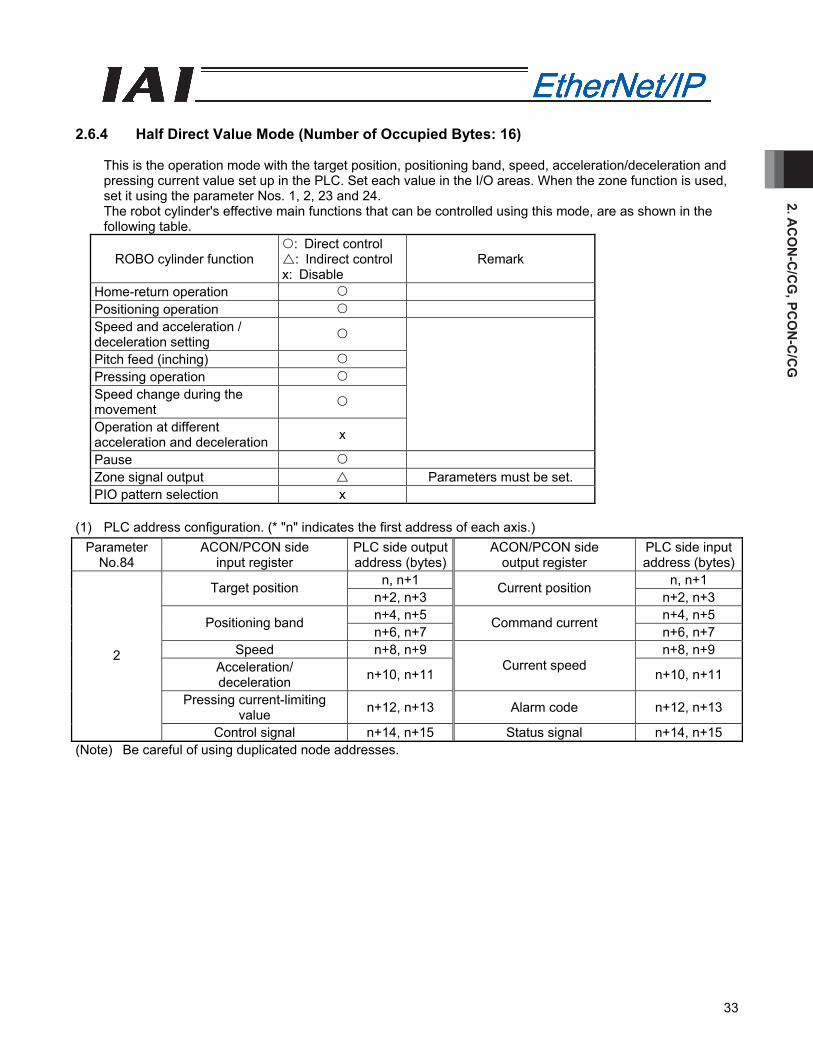
2.6.4 Half Direct Value Mode (Number of Occupied Bytes: 16)
This is the operation mode with the target position, positioning band, speed, acceleration/deceleration and pressing current value set up in the PLC. Set each value in the I/O areas. When the zone function is used, set it using the parameter Nos. 1, 2, 23 and 24. The robot cylinder's effective main functions that can be controlled using this mode, are as shown in the following table.
ROBO cylinder function : Direct control : Indirect control
x: Disable Remark
Home-return operation Positioning operation Speed and acceleration / deceleration setting
Pitch feed (inching) Pressing operation Speed change during the movement
Operation at different acceleration and deceleration x
Pause Zone signal output Parameters must be set. PIO pattern selection x
(1) PLC address configuration. (* "n" indicates the first address of each axis.)
Parameter No.84
ACON/PCON side input register
PLC side output address (bytes)
ACON/PCON side output register
PLC side input address (bytes)
n, n+1 n, n+1 Target position n+2, n+3
Current position n+2, n+3
n+4, n+5 n+4, n+5 Positioning band n+6, n+7
Command current n+6, n+7
Speed n+8, n+9 n+8, n+9 Acceleration/ deceleration n+10, n+11
Current speed n+10, n+11
Pressing current-limiting value n+12, n+13 Alarm code n+12, n+13
2
Control signal n+14, n+15 Status signal n+14, n+15 (Note) Be careful of using duplicated node addresses.
2. A
CO
N-C
/CG
, PC
ON
-C/C
G
34
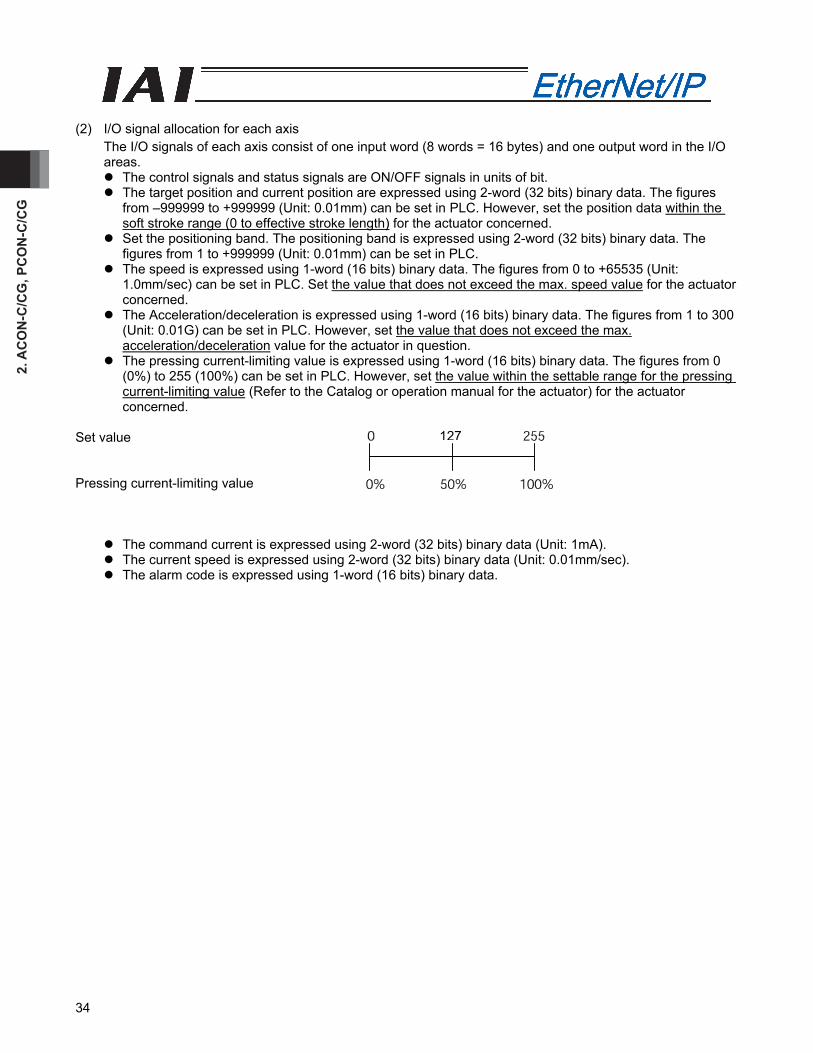
(2) I/O signal allocation for each axis
The I/O signals of each axis consist of one input word (8 words = 16 bytes) and one output word in the I/O areas.
The control signals and status signals are ON/OFF signals in units of bit. The target position and current position are expressed using 2-word (32 bits) binary data. The figures
from –999999 to +999999 (Unit: 0.01mm) can be set in PLC. However, set the position data within the soft stroke range (0 to effective stroke length) for the actuator concerned.
Set the positioning band. The positioning band is expressed using 2-word (32 bits) binary data. The figures from 1 to +999999 (Unit: 0.01mm) can be set in PLC.
The speed is expressed using 1-word (16 bits) binary data. The figures from 0 to +65535 (Unit: 1.0mm/sec) can be set in PLC. Set the value that does not exceed the max. speed value for the actuator concerned.
The Acceleration/deceleration is expressed using 1-word (16 bits) binary data. The figures from 1 to 300 (Unit: 0.01G) can be set in PLC. However, set the value that does not exceed the max. acceleration/deceleration value for the actuator in question.
The pressing current-limiting value is expressed using 1-word (16 bits) binary data. The figures from 0 (0%) to 255 (100%) can be set in PLC. However, set the value within the settable range for the pressing current-limiting value (Refer to the Catalog or operation manual for the actuator) for the actuator concerned.
Set value Pressing current-limiting value
The command current is expressed using 2-word (32 bits) binary data (Unit: 1mA). The current speed is expressed using 2-word (32 bits) binary data (Unit: 0.01mm/sec). The alarm code is expressed using 1-word (16 bits) binary data.
127
2. AC
ON
-C/C
G, PC
ON
-C/C
G
35
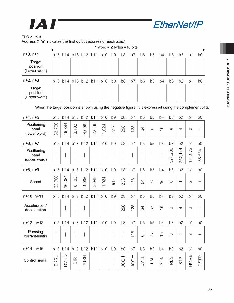
PLC output Address (* “n” indicates the first output address of each axis.)
When the target position is shown using the negative figure, it is expressed using the complement of 2.
1 word = 2 bytes =16 bits
Target position
(Lower word)
Target position
(Upper word)
n+2, n+3
n+0, n+1
Positioning band
(lower word)
Speed
Acceleration/ deceleration
Pressing current-limitin
Control signal
Positioning band
(upper word)
n+12, n+13
n+10, n+11
n+8, n+9
n+6, n+7
n+4, n+5
n+14, n+15
2. A
CO
N-C
/CG
, PC
ON
-C/C
G
36
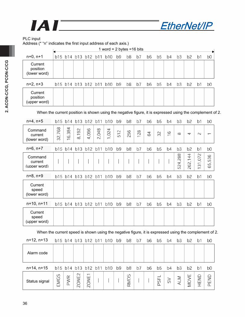
PLC input Address (* “n” indicates the first input address of each axis.)
When the current position is shown using the negative figure, it is expressed using the complement of 2. When the current speed is shown using the negative figure, it is expressed using the complement of 2.
Current position
(lower word)
Current position
(upper word)
1 word = 2 bytes =16 bits
n+2, n+3
n+0, n+1
Alarm code
Status signal
Command current
(lower word)
Command current
(upper word)
Current speed
(upper word)
Current speed
(lower word)
n+12, n+13
n+10, n+11
n+8, n+9
n+6, n+7
n+4, n+5
n+14, n+15
2. AC
ON
-C/C
G, PC
ON
-C/C
G
37
(3) I/O signal assignment (* “ON” in the table shows the corresponding bit of “1” and “OFF” shows “0”.)
Signal type Bit Symbol Contents Details
Target position
32-bit data -
32-bit signed Integer. Set the target position on the absolute coordinates. The unit is 0.01mm and settable range is between –999999 to +999999. (Example) When it is “+25.41mm”, set it as “2541”. If the value larger than the value (0.2mm) inside the soft limit for the parameter, the movement would be limited to the inside the soft limit (0.2mm). * When the input is performed in hexadecimal notation, input
the negative value using a complement of 2.
2.8 (2)
Positioning band
32-bit data -
32-bit integer The unit is 0.01mm and settable range is between 1 to +999999. (Example) When it is “25.40mm”, set it as “2540”. This register value has two meanings depending on the operation type. [1] In the case of positioning operation, it shows the
allowable range from the target position, that is regarded as the positioning completion.
[2] In the case of pressing operation, it shows the pressing width value. Specify the normal operation or pressing operation using the “PUSH” control signal setting.
2.8 (2)
Speed 16-bit data -
16-bit integer Specify the speed at which to move the actuator. The unit is 1.0mm/sec and settable range is 0 to 65535. Deceleration stop if and to specify in motion 0. It under suspension, it will remain stopped on the spot. (Example) When it is “254.0mm/sec”, set it as “254”. When the movement command is set with the value bigger than the max. speed, an alarm is issued.
2.8 (2)
PLC
out
put
Acceleration/ Deceleration
16-bit data -
16-bit integer Specify the acceleration / deceleration at which to move the actuator (the acceleration and deceleration will be the same value). The unit is 0.01G and settable range is 1 to 300. (Example) To set “0.30 G”, specify “30”. If a move command is issued by specifying “0” or any value exceeding the maximum acceleration or deceleration, an alarm will occur.
2.8 (2)
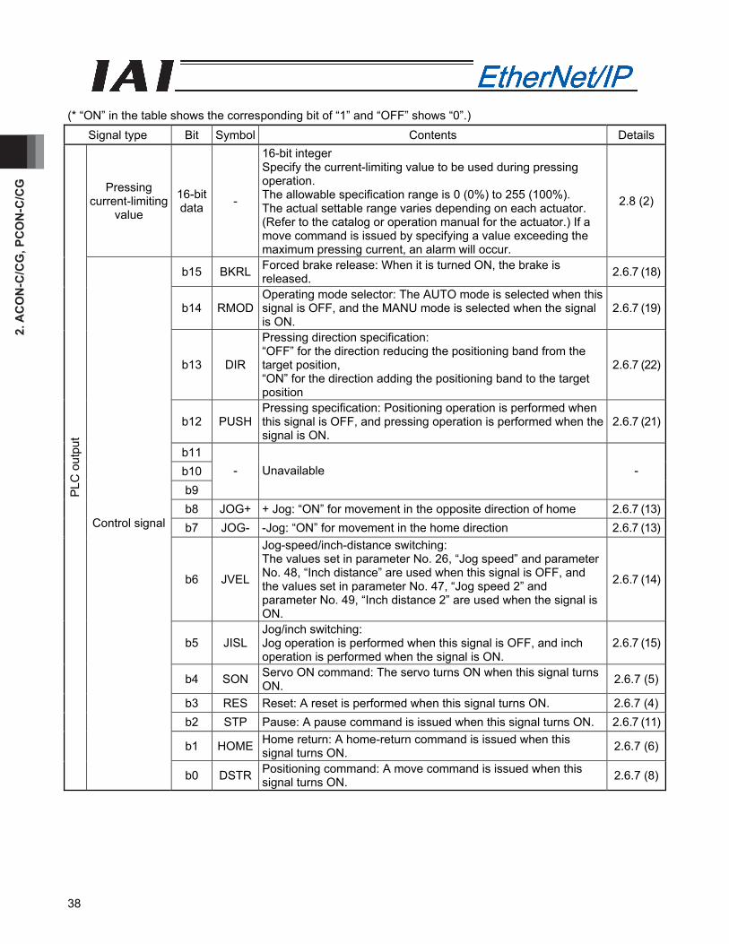
2. A
CO
N-C
/CG
, PC
ON
-C/C
G
38
(* “ON” in the table shows the corresponding bit of “1” and “OFF” shows “0”.)
Signal type Bit Symbol Contents Details
Pressing current-limiting
value
16-bit data -
16-bit integer Specify the current-limiting value to be used during pressing operation. The allowable specification range is 0 (0%) to 255 (100%). The actual settable range varies depending on each actuator. (Refer to the catalog or operation manual for the actuator.) If a move command is issued by specifying a value exceeding the maximum pressing current, an alarm will occur.
2.8 (2)
b15 BKRL Forced brake release: When it is turned ON, the brake is released. 2.6.7 (18)
b14 RMOD Operating mode selector: The AUTO mode is selected when this signal is OFF, and the MANU mode is selected when the signal is ON.
2.6.7 (19)
b13 DIR
Pressing direction specification: “OFF” for the direction reducing the positioning band from the target position, “ON” for the direction adding the positioning band to the target position
2.6.7 (22)
b12 PUSH Pressing specification: Positioning operation is performed when this signal is OFF, and pressing operation is performed when the signal is ON.
2.6.7 (21)
b11 b10 b9
- Unavailable -
b8 JOG+ + Jog: “ON” for movement in the opposite direction of home 2.6.7 (13)b7 JOG- -Jog: “ON” for movement in the home direction 2.6.7 (13)
b6 JVEL
Jog-speed/inch-distance switching: The values set in parameter No. 26, “Jog speed” and parameter No. 48, “Inch distance” are used when this signal is OFF, and the values set in parameter No. 47, “Jog speed 2” and parameter No. 49, “Inch distance 2” are used when the signal is ON.
2.6.7 (14)
b5 JISL Jog/inch switching: Jog operation is performed when this signal is OFF, and inch operation is performed when the signal is ON.
2.6.7 (15)
b4 SON Servo ON command: The servo turns ON when this signal turns ON. 2.6.7 (5)
b3 RES Reset: A reset is performed when this signal turns ON. 2.6.7 (4)b2 STP Pause: A pause command is issued when this signal turns ON. 2.6.7 (11)
b1 HOME Home return: A home-return command is issued when this signal turns ON. 2.6.7 (6)
PLC
out
put
Control signal
b0 DSTR Positioning command: A move command is issued when this signal turns ON. 2.6.7 (8)
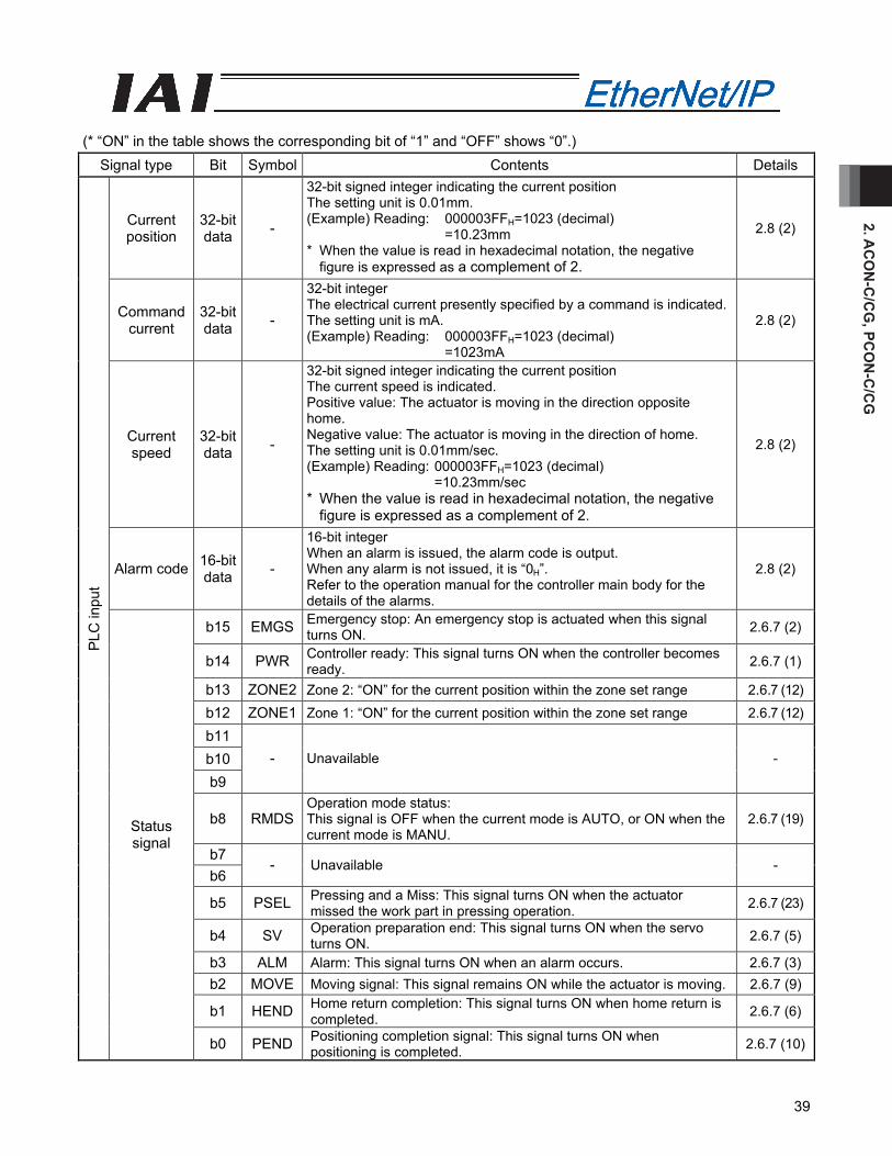
2. AC
ON
-C/C
G, PC
ON
-C/C
G
39
(* “ON” in the table shows the corresponding bit of “1” and “OFF” shows “0”.)
Signal type Bit Symbol Contents Details
Current position
32-bit data -
32-bit signed integer indicating the current position The setting unit is 0.01mm. (Example) Reading: 000003FFH=1023 (decimal)
=10.23mm * When the value is read in hexadecimal notation, the negative
figure is expressed as a complement of 2.
2.8 (2)
Command current
32-bit data -
32-bit integer The electrical current presently specified by a command is indicated.The setting unit is mA. (Example) Reading: 000003FFH=1023 (decimal)
=1023mA
2.8 (2)
Current speed
32-bit data -
32-bit signed integer indicating the current position The current speed is indicated. Positive value: The actuator is moving in the direction opposite home. Negative value: The actuator is moving in the direction of home. The setting unit is 0.01mm/sec. (Example) Reading: 000003FFH=1023 (decimal)
=10.23mm/sec * When the value is read in hexadecimal notation, the negative
figure is expressed as a complement of 2.
2.8 (2)
Alarm code 16-bit data -
16-bit integer When an alarm is issued, the alarm code is output. When any alarm is not issued, it is “0H”. Refer to the operation manual for the controller main body for the details of the alarms.
2.8 (2)
b15 EMGS Emergency stop: An emergency stop is actuated when this signal turns ON. 2.6.7 (2)
b14 PWR Controller ready: This signal turns ON when the controller becomes ready. 2.6.7 (1)
b13 ZONE2 Zone 2: “ON” for the current position within the zone set range 2.6.7 (12)
b12 ZONE1 Zone 1: “ON” for the current position within the zone set range 2.6.7 (12)
b11 b10 b9
- Unavailable -
b8 RMDS Operation mode status: This signal is OFF when the current mode is AUTO, or ON when the current mode is MANU.
2.6.7 (19)
b7 b6
- Unavailable -
b5 PSEL Pressing and a Miss: This signal turns ON when the actuator missed the work part in pressing operation. 2.6.7 (23)
b4 SV Operation preparation end: This signal turns ON when the servo turns ON. 2.6.7 (5)
b3 ALM Alarm: This signal turns ON when an alarm occurs. 2.6.7 (3)b2 MOVE Moving signal: This signal remains ON while the actuator is moving. 2.6.7 (9)
b1 HEND Home return completion: This signal turns ON when home return is completed. 2.6.7 (6)
PLC
inpu
t
Status signal
b0 PEND Positioning completion signal: This signal turns ON when positioning is completed. 2.6.7 (10)
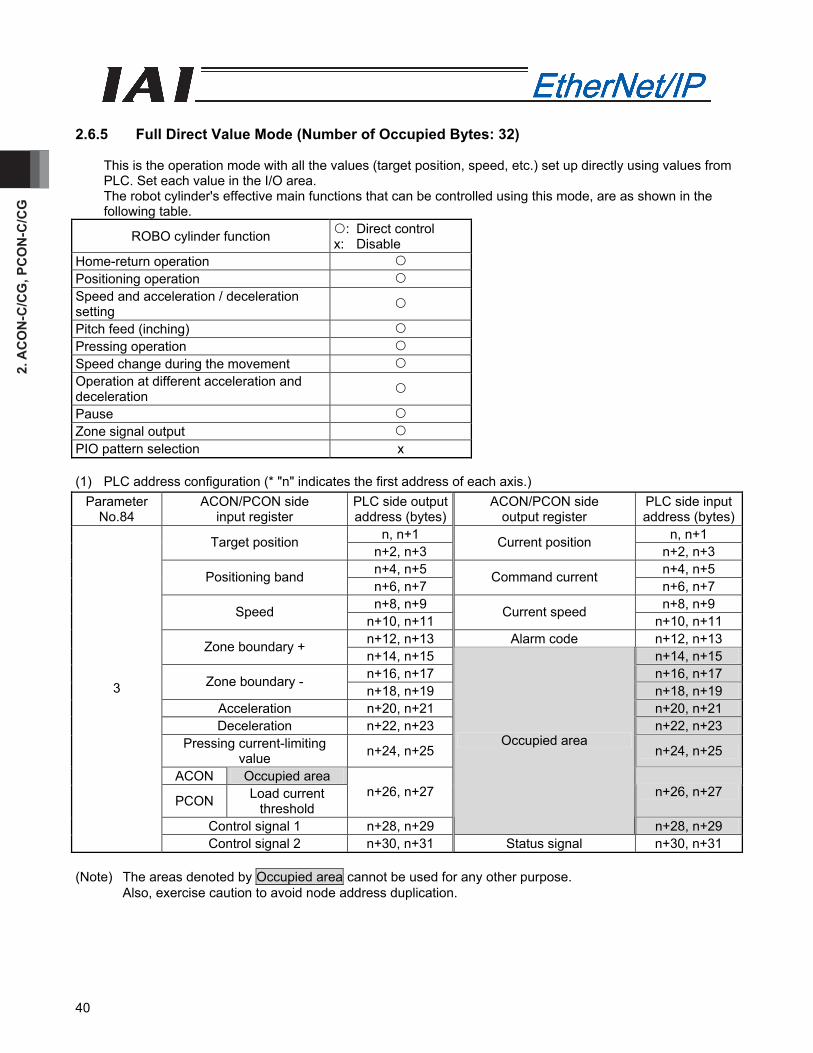
2. A
CO
N-C
/CG
, PC
ON
-C/C
G
40
2.6.5 Full Direct Value Mode (Number of Occupied Bytes: 32)
This is the operation mode with all the values (target position, speed, etc.) set up directly using values from PLC. Set each value in the I/O area. The robot cylinder's effective main functions that can be controlled using this mode, are as shown in the following table.
ROBO cylinder function : Direct control x: Disable
Home-return operation Positioning operation Speed and acceleration / deceleration setting
Pitch feed (inching) Pressing operation Speed change during the movement Operation at different acceleration and deceleration
Pause Zone signal output PIO pattern selection x (1) PLC address configuration (* "n" indicates the first address of each axis.)
Parameter No.84
ACON/PCON side input register
PLC side output address (bytes)
ACON/PCON side output register
PLC side input address (bytes)
n, n+1 n, n+1 Target position n+2, n+3
Current position n+2, n+3
n+4, n+5 n+4, n+5 Positioning band n+6, n+7
Command current n+6, n+7
n+8, n+9 n+8, n+9 Speed n+10, n+11
Current speed n+10, n+11
n+12, n+13 Alarm code n+12, n+13 Zone boundary + n+14, n+15 n+14, n+15 n+16, n+17 n+16, n+17 Zone boundary - n+18, n+19 n+18, n+19
Acceleration n+20, n+21 n+20, n+21 Deceleration n+22, n+23 n+22, n+23
Pressing current-limiting value n+24, n+25 n+24, n+25
ACON Occupied area
PCON Load current threshold
n+26, n+27 n+26, n+27
Control signal 1 n+28, n+29
Occupied area
n+28, n+29
3
Control signal 2 n+30, n+31 Status signal n+30, n+31 (Note) The areas denoted by Occupied area cannot be used for any other purpose.
Also, exercise caution to avoid node address duplication.
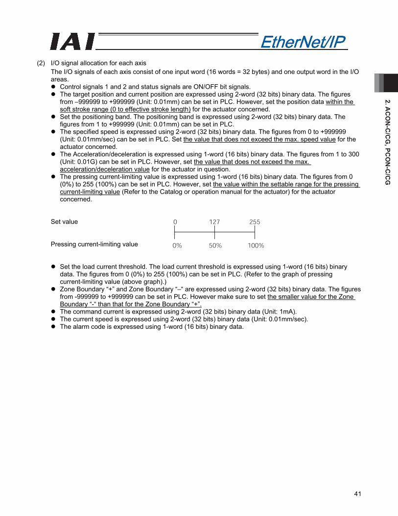
2. AC
ON
-C/C
G, PC
ON
-C/C
G
41
(2) I/O signal allocation for each axis
The I/O signals of each axis consist of one input word (16 words = 32 bytes) and one output word in the I/O areas.
Control signals 1 and 2 and status signals are ON/OFF bit signals. The target position and current position are expressed using 2-word (32 bits) binary data. The figures
from –999999 to +999999 (Unit: 0.01mm) can be set in PLC. However, set the position data within the soft stroke range (0 to effective stroke length) for the actuator concerned.
Set the positioning band. The positioning band is expressed using 2-word (32 bits) binary data. The figures from 1 to +999999 (Unit: 0.01mm) can be set in PLC.
The specified speed is expressed using 2-word (32 bits) binary data. The figures from 0 to +999999 (Unit: 0.01mm/sec) can be set in PLC. Set the value that does not exceed the max. speed value for the actuator concerned.
The Acceleration/deceleration is expressed using 1-word (16 bits) binary data. The figures from 1 to 300 (Unit: 0.01G) can be set in PLC. However, set the value that does not exceed the max. acceleration/deceleration value for the actuator in question.
The pressing current-limiting value is expressed using 1-word (16 bits) binary data. The figures from 0 (0%) to 255 (100%) can be set in PLC. However, set the value within the settable range for the pressing current-limiting value (Refer to the Catalog or operation manual for the actuator) for the actuator concerned.
Set value Pressing current-limiting value
Set the load current threshold. The load current threshold is expressed using 1-word (16 bits) binary data. The figures from 0 (0%) to 255 (100%) can be set in PLC. (Refer to the graph of pressing current-limiting value (above graph).)
Zone Boundary “+” and Zone Boundary “–“ are expressed using 2-word (32 bits) binary data. The figures from -999999 to +999999 can be set in PLC. However make sure to set the smaller value for the Zone Boundary “-“ than that for the Zone Boundary “+”.
The command current is expressed using 2-word (32 bits) binary data (Unit: 1mA). The current speed is expressed using 2-word (32 bits) binary data (Unit: 0.01mm/sec). The alarm code is expressed using 1-word (16 bits) binary data.
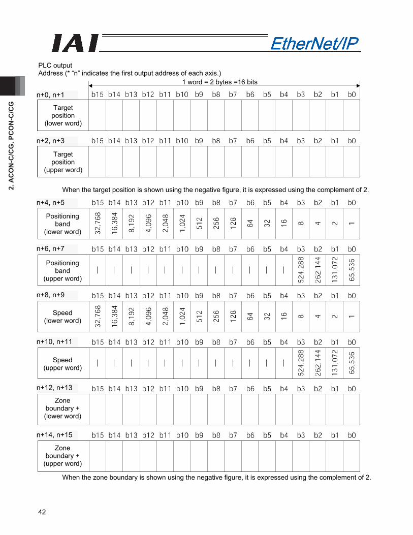
2. A
CO
N-C
/CG
, PC
ON
-C/C
G
42
PLC output Address (* “n” indicates the first output address of each axis.)
When the target position is shown using the negative figure, it is expressed using the complement of 2.
When the zone boundary is shown using the negative figure, it is expressed using the complement of 2.
1 word = 2 bytes =16 bits
Target position
(lower word)
Target position
(upper word)
n+2, n+3
n+0, n+1
Positioning band
(lower word)
Positioning band
(upper word)
Speed (lower word)
Zone boundary + (lower word)
Speed (upper word)
Zone boundary +
(upper word)
n+12, n+13
n+10, n+11
n+8, n+9
n+6, n+7
n+4, n+5
n+14, n+15
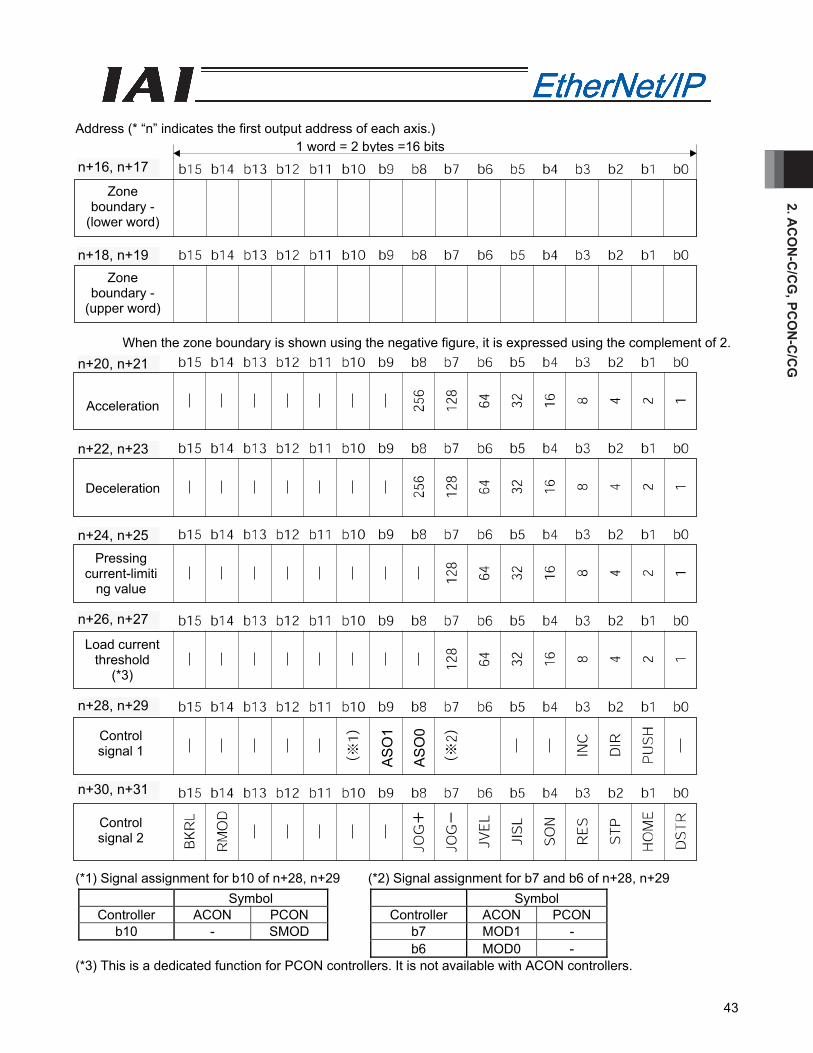
2. AC
ON
-C/C
G, PC
ON
-C/C
G
43
Address (* “n” indicates the first output address of each axis.)
When the zone boundary is shown using the negative figure, it is expressed using the complement of 2.
(*1) Signal assignment for b10 of n+28, n+29 (*2) Signal assignment for b7 and b6 of n+28, n+29
Symbol Symbol Controller ACON PCON Controller ACON PCON
b10 - SMOD b7 MOD1 - b6 MOD0 -
(*3) This is a dedicated function for PCON controllers. It is not available with ACON controllers.
1 word = 2 bytes =16 bits
Zone boundary -
(lower word)
Zone boundary -
(upper word)
Control signal 2
Acceleration
Deceleration
Pressing current-limiti
ng value
Load current threshold
(*3)
Control signal 1
n+28, n+29
n+26, n+27
n+24, n+25
n+22, n+23
n+20, n+21
n+18, n+19
n+16, n+17
n+30, n+31
AS
O1
AS
O0
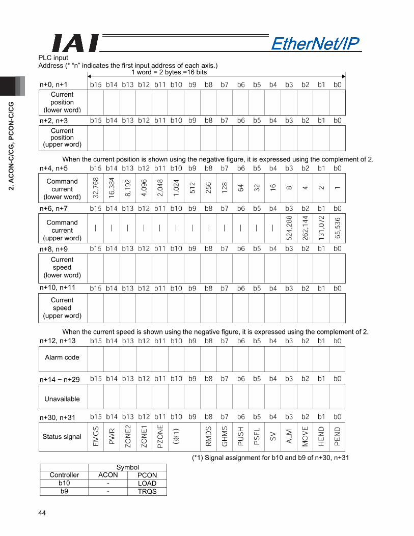
2. A
CO
N-C
/CG
, PC
ON
-C/C
G
44
PLC input Address (* “n” indicates the first input address of each axis.)
When the current position is shown using the negative figure, it is expressed using the complement of 2. When the current speed is shown using the negative figure, it is expressed using the complement of 2.
(*1) Signal assignment for b10 and b9 of n+30, n+31
Symbol Controller ACON PCON
b10 - LOAD b9 - TRQS
Current position
(lower word)
1 word = 2 bytes =16 bits
n+0, n+1
Current position
(upper word)
n+2, n+3
Command current
(lower word)
n+4, n+5
Command current
(upper word)
n+6, n+7
Current speed
(lower word)
n+8, n+9
Current speed
(upper word)
n+10, n+11
Alarm code
n+12, n+13
Unavailable
n+14 ~ n+29
Status signal
n+30, n+31
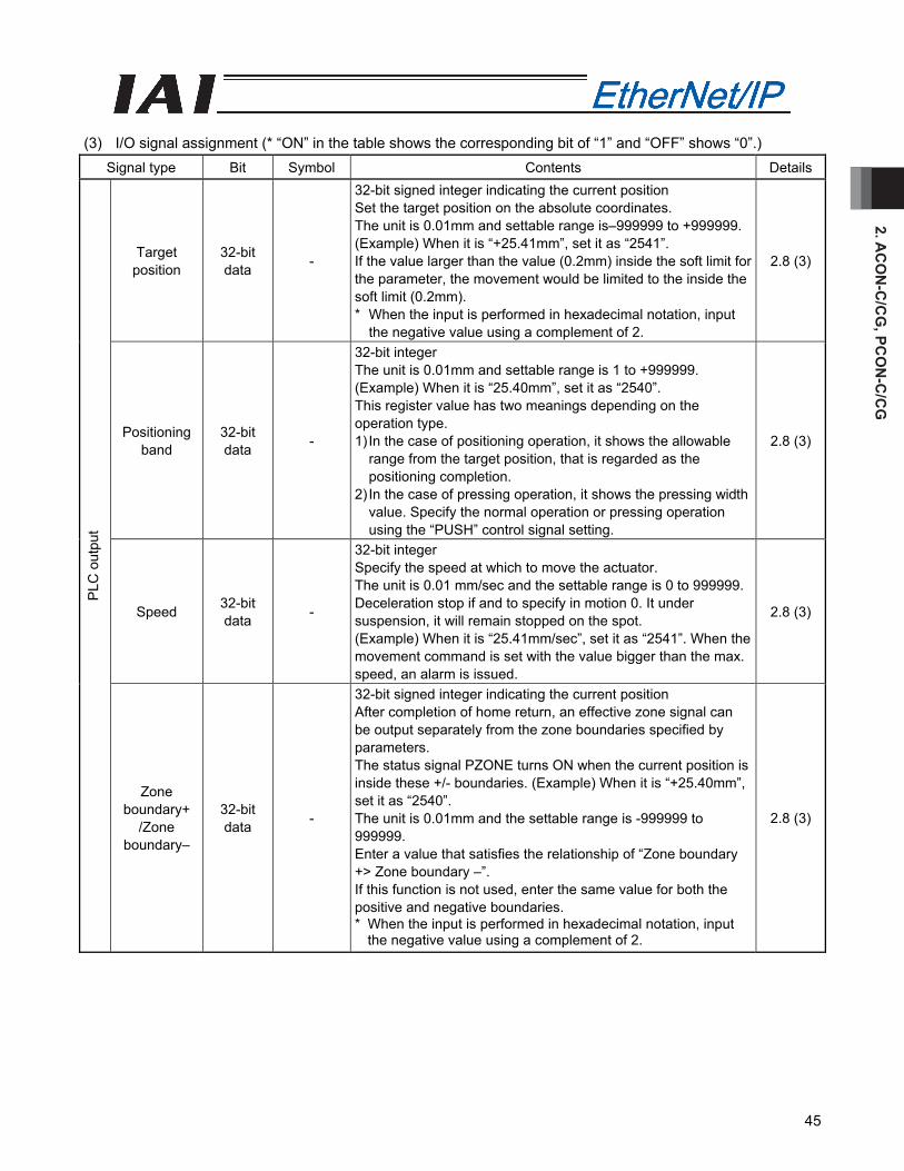
2. AC
ON
-C/C
G, PC
ON
-C/C
G
45
(3) I/O signal assignment (* “ON” in the table shows the corresponding bit of “1” and “OFF” shows “0”.)
Signal type Bit Symbol Contents Details
Target position
32-bit data -
32-bit signed integer indicating the current position Set the target position on the absolute coordinates. The unit is 0.01mm and settable range is–999999 to +999999. (Example) When it is “+25.41mm”, set it as “2541”. If the value larger than the value (0.2mm) inside the soft limit for the parameter, the movement would be limited to the inside the soft limit (0.2mm). * When the input is performed in hexadecimal notation, input
the negative value using a complement of 2.
2.8 (3)
Positioning band
32-bit data -
32-bit integer The unit is 0.01mm and settable range is 1 to +999999. (Example) When it is “25.40mm”, set it as “2540”. This register value has two meanings depending on the operation type. 1) In the case of positioning operation, it shows the allowable
range from the target position, that is regarded as the positioning completion.
2) In the case of pressing operation, it shows the pressing width value. Specify the normal operation or pressing operation using the “PUSH” control signal setting.
2.8 (3)
Speed 32-bit data -
32-bit integer Specify the speed at which to move the actuator. The unit is 0.01 mm/sec and the settable range is 0 to 999999. Deceleration stop if and to specify in motion 0. It under suspension, it will remain stopped on the spot. (Example) When it is “25.41mm/sec”, set it as “2541”. When the movement command is set with the value bigger than the max. speed, an alarm is issued.
2.8 (3)
PLC
out
put
Zone boundary+
/Zone boundary–
32-bit data -
32-bit signed integer indicating the current position After completion of home return, an effective zone signal can be output separately from the zone boundaries specified by parameters. The status signal PZONE turns ON when the current position is inside these +/- boundaries. (Example) When it is “+25.40mm”, set it as “2540”. The unit is 0.01mm and the settable range is -999999 to 999999. Enter a value that satisfies the relationship of “Zone boundary +> Zone boundary –”. If this function is not used, enter the same value for both the positive and negative boundaries. * When the input is performed in hexadecimal notation, input
the negative value using a complement of 2.
2.8 (3)
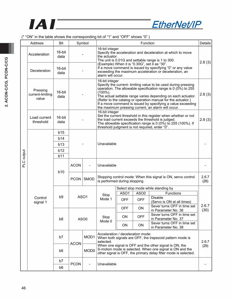
2. A
CO
N-C
/CG
, PC
ON
-C/C
G
46
(* “ON” in the table shows the corresponding bit of “1” and “OFF” shows “0”.)
Address Bit Symbol Function Details
Acceleration 16-bit data -
Deceleration 16-bit data -
16-bit integer Specify the acceleration and deceleration at which to move the actuator. The unit is 0.01G and settable range is 1 to 300. (Example) When it is “0.30G”, set it as “30”. If a move command is issued by specifying “0” or any value exceeding the maximum acceleration or deceleration, an alarm will occur.
2.8 (3)
Pressing current-limiting
value
16-bit data -
16-bit integer Specify the current- limiting value to be used during pressing operation. The allowable specification range is 0 (0%) to 255 (100%). The actual settable range varies depending on each actuator. (Refer to the catalog or operation manual for the actuator.) If a move command is issued by specifying a value exceeding the maximum pressing current, an alarm will occur.
2.8 (3)
Load current threshold
16-bit data -
16-bit integer Set the current threshold in this register when whether or not the load current exceeds the threshold is judged. The allowable specification range is 0 (0%) to 255 (100%). If threshold judgment is not required, enter “0”.
2.8 (3)
b15 b14 b13 b12 b11
- Unavailable -
ACON - Unavailable -
b10
PCON SMOD Stopping control mode: When this signal is ON, servo control is performed during stopping.
2.6.7 (28)
b9 ASO1 Stop Mode 1
b8 ASO0 Stop Mode 0
Select stop mode while standing by ASO1 ASO0 Functions
OFF OFF Disable (Servo is ON at all times)
OFF ON Sever turns OFF in time setin Parameter No. 36
ON OFF Sever turns OFF in time setin Parameter No. 37
ON ON Sever turns OFF in time setin Parameter No. 38
2.6.7 (30)
b7 MOD1
b6
ACON
MOD0
Acceleration / deceleration mode: When both signals are OFF, the trapezoid pattern mode is selected. When one signal is OFF and the other signal is ON, the S-motion mode is selected. When one signal is ON and the other signal is OFF, the primary delay filter mode is selected.
2.6.7 (29)
b7
PLC
out
put
Control signal 1
b6 PCON - Unavailable -
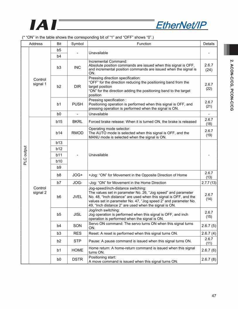
2. AC
ON
-C/C
G, PC
ON
-C/C
G
47
(* “ON” in the table shows the corresponding bit of “1” and “OFF” shows “0”.)
Address Bit Symbol Function Details
b5 b4
- Unavailable -
b3 INC Incremental Command: Absolute position commands are issued when this signal is OFF, and incremental position commands are issued when the signal is ON.
2.6.7 (24)
b2 DIR
Pressing direction specification: “OFF” for the direction reducing the positioning band from the target position “ON” for the direction adding the positioning band to the target position
2.6.7 (22)
b1 PUSH Pressing specification : Positioning operation is performed when this signal is OFF, and pressing operation is performed when the signal is ON.
2.6.7 (21)
Control signal 1
b0 - Unavailable -
b15 BKRL Forced brake release: When it is turned ON, the brake is released 2.6.7 (18)
b14 RMOD Operating mode selector: The AUTO mode is selected when this signal is OFF, and the MANU mode is selected when the signal is ON.
2.6.7 (19)
b13 b12 b11 b10 b9
- Unavailable -
b8 JOG+ +Jog: “ON” for Movement in the Opposite Direction of Home 2.6.7 (13)
b7 JOG- -Jog: “ON” for Movement in the Home Direction 2.7.7 (13)
b6 JVEL
Jog-speed/inch-distance switching: The values set in parameter No. 26, “Jog speed” and parameter No. 48, “Inch distance” are used when this signal is OFF, and the values set in parameter No. 47, “Jog speed 2” and parameter No. 49, “Inch distance 2” are used when the signal is ON.
2.6.7 (14)
b5 JISL Jog/inch switching: Jog operation is performed when this signal is OFF, and inch operation is performed when the signal is ON.
2.6.7 (15)
b4 SON Servo ON command: The servo turns ON when this signal turns ON. 2.6.7 (5)
b3 RES Reset: A reset is performed when this signal turns ON. 2.6.7 (4)
b2 STP Pause: A pause command is issued when this signal turns ON. 2.6.7 (11)
b1 HOME Home return: A home-return command is issued when this signal turns ON. 2.6.7 (6)
PLC
out
put
Control signal 2
b0 DSTR Positioning start: A move command is issued when this signal turns ON. 2.6.7 (8)
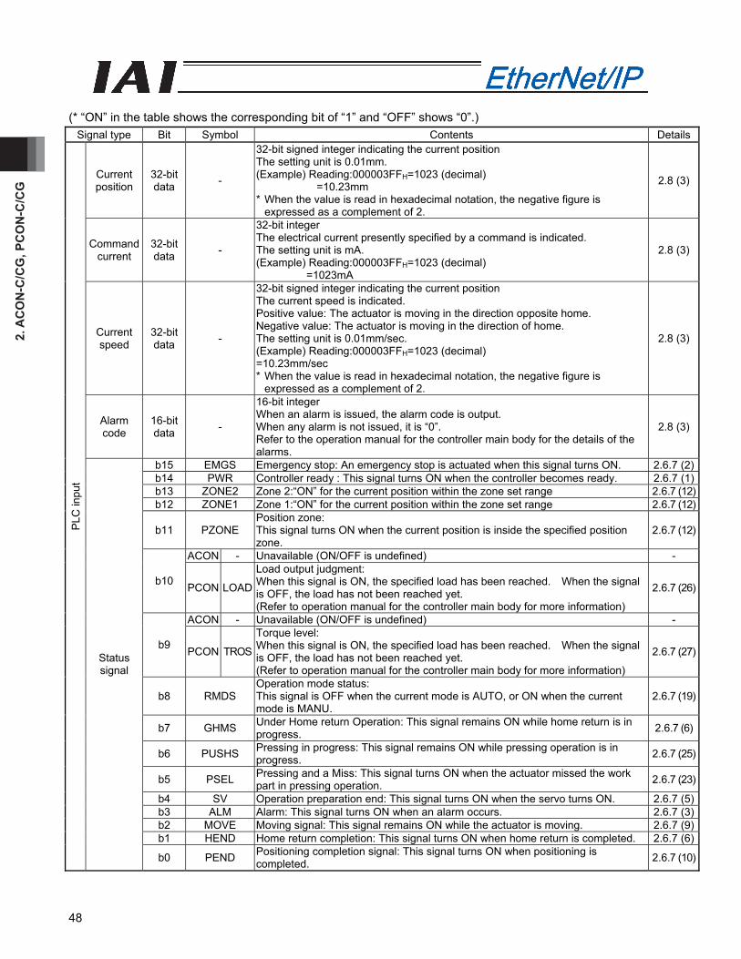
2. A
CO
N-C
/CG
, PC
ON
-C/C
G
48
(* “ON” in the table shows the corresponding bit of “1” and “OFF” shows “0”.)
Signal type Bit Symbol Contents Details
Current position
32-bit data -
32-bit signed integer indicating the current position The setting unit is 0.01mm. (Example) Reading:000003FFH=1023 (decimal) =10.23mm * When the value is read in hexadecimal notation, the negative figure is
expressed as a complement of 2.
2.8 (3)
Command current
32-bit data -
32-bit integer The electrical current presently specified by a command is indicated. The setting unit is mA. (Example) Reading:000003FFH=1023 (decimal) =1023mA
2.8 (3)
Current speed
32-bit data -
32-bit signed integer indicating the current position The current speed is indicated. Positive value: The actuator is moving in the direction opposite home. Negative value: The actuator is moving in the direction of home. The setting unit is 0.01mm/sec. (Example) Reading:000003FFH=1023 (decimal) =10.23mm/sec * When the value is read in hexadecimal notation, the negative figure is
expressed as a complement of 2.
2.8 (3)
Alarm code
16-bit data -
16-bit integer When an alarm is issued, the alarm code is output. When any alarm is not issued, it is “0”. Refer to the operation manual for the controller main body for the details of the alarms.
2.8 (3)
b15 EMGS Emergency stop: An emergency stop is actuated when this signal turns ON. 2.6.7 (2)b14 PWR Controller ready : This signal turns ON when the controller becomes ready. 2.6.7 (1)b13 ZONE2 Zone 2:“ON” for the current position within the zone set range 2.6.7 (12)b12 ZONE1 Zone 1:“ON” for the current position within the zone set range 2.6.7 (12)
b11 PZONE Position zone: This signal turns ON when the current position is inside the specified position zone.
2.6.7 (12)
ACON - Unavailable (ON/OFF is undefined) -
b10 PCON LOAD
Load output judgment: When this signal is ON, the specified load has been reached. When the signal is OFF, the load has not been reached yet. (Refer to operation manual for the controller main body for more information)
2.6.7 (26)
ACON - Unavailable (ON/OFF is undefined) -
b9 PCON TROS
Torque level: When this signal is ON, the specified load has been reached. When the signal is OFF, the load has not been reached yet. (Refer to operation manual for the controller main body for more information)
2.6.7 (27)
b8 RMDS Operation mode status: This signal is OFF when the current mode is AUTO, or ON when the current mode is MANU.
2.6.7 (19)
b7 GHMS Under Home return Operation: This signal remains ON while home return is in progress. 2.6.7 (6)
b6 PUSHS Pressing in progress: This signal remains ON while pressing operation is in progress. 2.6.7 (25)
b5 PSEL Pressing and a Miss: This signal turns ON when the actuator missed the work part in pressing operation. 2.6.7 (23)
b4 SV Operation preparation end: This signal turns ON when the servo turns ON. 2.6.7 (5)b3 ALM Alarm: This signal turns ON when an alarm occurs. 2.6.7 (3)b2 MOVE Moving signal: This signal remains ON while the actuator is moving. 2.6.7 (9)b1 HEND Home return completion: This signal turns ON when home return is completed. 2.6.7 (6)
PLC
inpu
t
Status signal
b0 PEND Positioning completion signal: This signal turns ON when positioning is completed. 2.6.7 (10)

2. AC
ON
-C/C
G, PC
ON
-C/C
G
49
2.6.6 Remote I/O Mode 2 (Number of Occupied Bytes: 12)
In this operation method, EtherNet/IP communications is used to mimic the operation of hardware PIO (24V I/O). Set the position data using the teaching tools. The number of operable positions varies depending on the parameter No. 25 “PIO Pattern” setting. This mode is the same as the remote I/O mode, but the current-position read function and command-current read function are also available. The features of each PIO pattern are shown below. (Refer to operation manual for the controller main body for more information)
Value set in parameter No. 25 Operation mode I/O specification
0 Positioning mode 64 positioning points and two zone output points are available. 1 Teaching mode 64 positioning points and one zone output point are available.
Positioning operation and jog operation are supported. The current position can be written to a specified position.
2 256-point mode 256 positioning points and one zone output point are available. 3 512-point mode 512 positioning points are available. There are no zone outputs. 4 Electromagnetic
valve mode 1 7 positioning points and two zone output points are available. The direct operation command is available for each position No. A position complete signal is output for each position number.
5 Electromagnetic valve mode 2
3 positioning points and two zone output points are available. The actuator is operated by specifying forward, backward and intermediate position commands. A position complete signal is output separately for the front end, rear end and intermediate position.
The robot cylinder's effective main functions that can be controlled using this mode, are as shown in the following table.
PIO Pattern
ROBO cylinder function 0: Positioning mode
1: Teaching mode
2: 256-point mode
3: 512-point mode
4: Electro- magnetic valve mode 1
5: Electro- magnetic valve mode 2
Home-return operation x
Positioning operation Speed and acceleration/ deceleration setting
Pitch feed (inching)
Pressing operation x Speed change during the movement x
Operation at different acceleration and deceleration
Pause (*1)
Zone signal output x PIO pattern selection (set by a parameter)
: Supported, x: Not supported
(*1) It is available when the parameter No. 27 “Movement Command Type” is set to “0”. Turning “OFF” the “Movement Command” can stop the system temporarily.

2. A
CO
N-C
/CG
, PC
ON
-C/C
G
50
(1) PLC address configuration (* “n” indicates the first address of each axis.)
Parameter No.84
ACON/PCON side DI and input register
PLC side output address (bytes)
ACON/PCON side DO and output register
PLC side input address (bytes)
Port No.0 to 15 n, n+1 Port No.0 to 15 n, n+1 n+2, n+3 Occupied area n+2, n+3 n+4, n+5 n+4, n+5 n+6, n+7
Current position n+6, n+7
n+8, n+9 n+8, n+9
4 Occupied area
n+10, n+11 Command current
n+10, n+11
(Note) The areas denoted by Occupied area cannot be used for any other purpose. Also, exercise caution to avoid node address duplication.
(2) I/O signal allocation for each axis
The I/O signals of each axis consist of 6 input words (channels) and 6 output words (6 words=12 bytes) in the I/O areas.
The areas controlled by port number are controlled using ON/OFF bit signals. The current position is a 2-word (32-bit) binary data (unit: 0.01 mm). The command current is expressed using 2-word (32 bits) binary data (Unit: 1mA).
PLC output Address (* “n” indicates the first output address of each axis.)
1 word = 2 bytes =16 bits
Controller input port number
n+0、n+1n+0, n+1
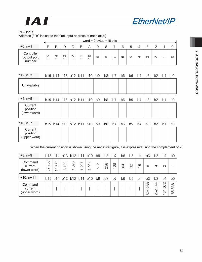
2. AC
ON
-C/C
G, PC
ON
-C/C
G
51
PLC input Address (* “n” indicates the first input address of each axis.)
When the current position is shown using the negative figure, it is expressed using the complement of 2.
1 word = 2 bytes =16 bits
Controller output port
number
Unavailable
Current position
(lower word)
Current position
(upper word)
n+6, n+7
n+4, n+5
n+2, n+3
n+0, n+1
Command current
(upper word)
Command current
(lower word)
n+10, n+11
n+8, n+9
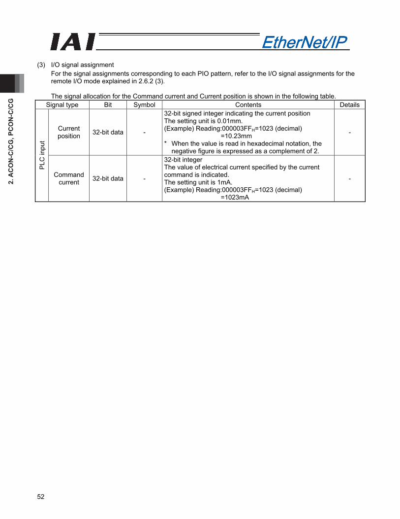
2. A
CO
N-C
/CG
, PC
ON
-C/C
G
52
(3) I/O signal assignment
For the signal assignments corresponding to each PIO pattern, refer to the I/O signal assignments for the remote I/O mode explained in 2.6.2 (3).
The signal allocation for the Command current and Current position is shown in the following table.
Signal type Bit Symbol Contents Details
Current position 32-bit data -
32-bit signed integer indicating the current position The setting unit is 0.01mm. (Example) Reading:000003FFH=1023 (decimal)
=10.23mm * When the value is read in hexadecimal notation, the
negative figure is expressed as a complement of 2.
-
PLC
inpu
t
Command current 32-bit data -
32-bit integer The value of electrical current specified by the current command is indicated. The setting unit is 1mA. (Example) Reading:000003FFH=1023 (decimal)
=1023mA
-
2. AC
ON
-C/C
G, PC
ON
-C/C
G
53
2.6.7 I/O Signal Controls and Function
* ON indicates that the applicable bit signal is “1”, while OFF indicates that the bit signal is “0”. The I/O control and functions used in the Position/Simplified Direct Value Mode, Half direct value mode and Full direct value mode, are described as follows. For the I/O signals for the Remote I/O mode and Remote I/O mode 2, refer to the controller’s operational manual.
(1) Controller ready (PWR) PLC input signal
When the controller can control the system after the power is applied, it is turned “ON”. ■ Function Regardless of the alarm or servo conditions, when the controller initialization is completed normally after the power is applied and the controller can control the system, it is turned “ON”. Even in the alarm condition, when the controller can control the system, it is turned “ON”.
(2) Emergency stop (EMGS) PLC input signal
When the controller is stopped in an emergency, it is turned “ON”. ■ Function When the controller is stopped in an emergency (motor driving power is cut off), it is turned “ON”. When the emergency stop status is cleared, it is turned “OFF”.
(3) Alarm (ALM) PLC input signal
When any error is detected using the controller protection circuit (function), it is turned “ON”. ■ Function When any error is detected and the protection circuit (function) is activated, this signal is turned “ON”. When the cause of the alarm is eliminated and the reset signal is turned “ON”, the alarm is turned “OFF” in the case that it is the alarm with the operation cancellation level. (In the case of the alarm with the cold start level, cycling of the power is required) When the alarm is detected, the Status Indicator LED (Refer to 2.3, "EtherNet/IP Interface”) on the front surface of the controller illuminates in red.
(4) Reset (RES) PLC output signal
This signal has two functions. It can reset the controller alarm and cancel the reminder for planned movements during pause conditions. ■ Function
[1] When this signal is turned ON from OFF condition after eliminating the cause of the alarm during the alarm output, the alarm (ALM) signal can be reset. (In the case of the alarm with the cold start level, cycling of the power is required)
[2] When this signal is turned ON from OFF condition during the pause condition, the reminder of the planned movement left can be cancelled.
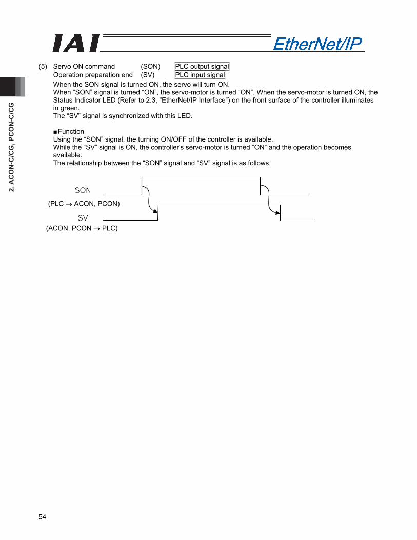
2. A
CO
N-C
/CG
, PC
ON
-C/C
G
54
(5) Servo ON command (SON) PLC output signal
Operation preparation end (SV) PLC input signal When the SON signal is turned ON, the servo will turn ON. When “SON” signal is turned “ON”, the servo-motor is turned “ON”. When the servo-motor is turned ON, the Status Indicator LED (Refer to 2.3, "EtherNet/IP Interface”) on the front surface of the controller illuminates in green. The “SV” signal is synchronized with this LED.
■ Function Using the “SON” signal, the turning ON/OFF of the controller is available. While the “SV” signal is ON, the controller's servo-motor is turned “ON” and the operation becomes available. The relationship between the “SON” signal and “SV” signal is as follows.
(PLC → ACON, PCON)
(ACON, PCON → PLC)
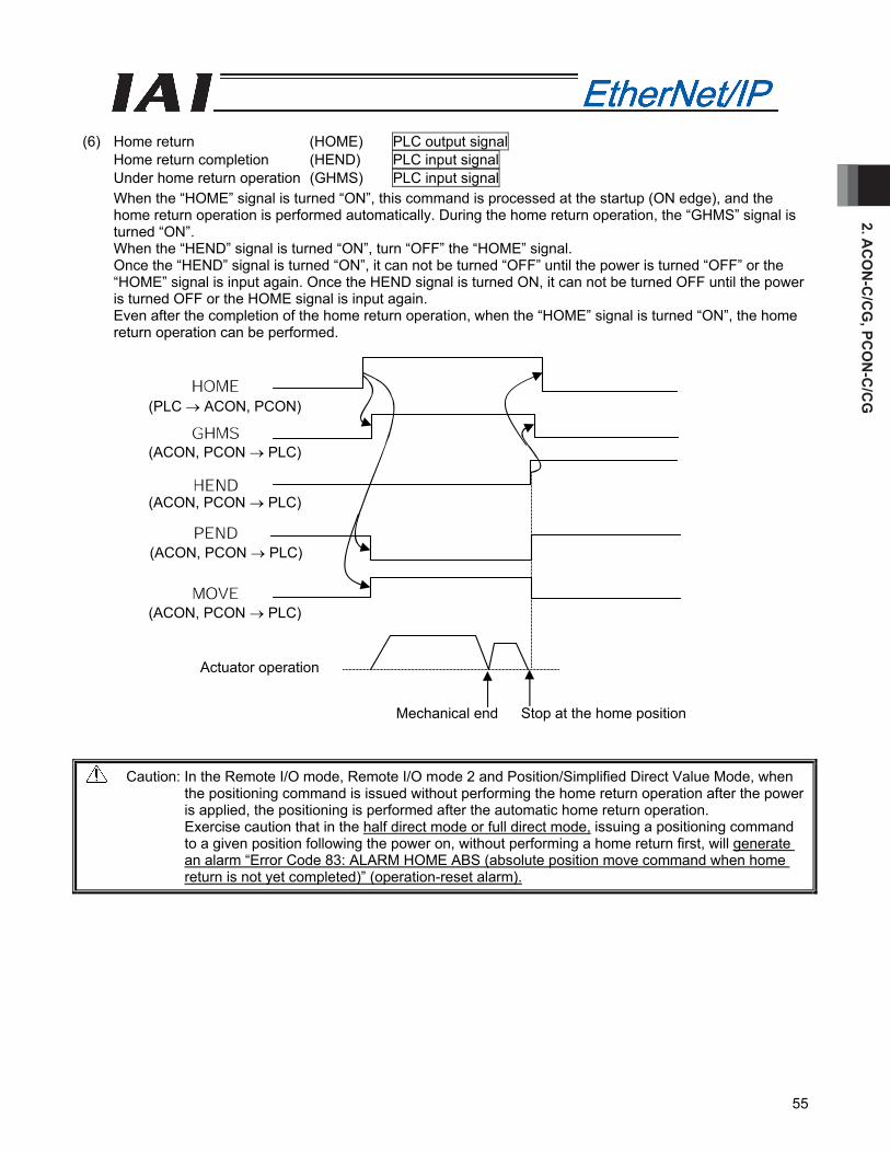
2. AC
ON
-C/C
G, PC
ON
-C/C
G
55
(6) Home return (HOME) PLC output signal
Home return completion (HEND) PLC input signal Under home return operation (GHMS) PLC input signal When the “HOME” signal is turned “ON”, this command is processed at the startup (ON edge), and the home return operation is performed automatically. During the home return operation, the “GHMS” signal is turned “ON”. When the “HEND” signal is turned “ON”, turn “OFF” the “HOME” signal. Once the “HEND” signal is turned “ON”, it can not be turned “OFF” until the power is turned “OFF” or the “HOME” signal is input again. Once the HEND signal is turned ON, it can not be turned OFF until the power is turned OFF or the HOME signal is input again. Even after the completion of the home return operation, when the “HOME” signal is turned “ON”, the home return operation can be performed.
Caution: In the Remote I/O mode, Remote I/O mode 2 and Position/Simplified Direct Value Mode, when the positioning command is issued without performing the home return operation after the power is applied, the positioning is performed after the automatic home return operation. Exercise caution that in the half direct mode or full direct mode, issuing a positioning command to a given position following the power on, without performing a home return first, will generate an alarm “Error Code 83: ALARM HOME ABS (absolute position move command when home return is not yet completed)” (operation-reset alarm).
(PLC → ACON, PCON)
(ACON, PCON → PLC)
(ACON, PCON → PLC)
(ACON, PCON → PLC)
(ACON, PCON → PLC)
Actuator operation
Mechanical end Stop at the home position

2. A
CO
N-C
/CG
, PC
ON
-C/C
G
56
(7) Positioning start (CSTR): Used in the position/simple direct mode PLC output signal
This signal is processed at the startup (ON edge) and the positioning is performed to the target position with the specified position No. or set using the PLC's target position register. Whether if the target position with the specified position No. is used or the setting using the PLC's target position register is used, depends on the Control signal b11: “Position/Simplified Direct Value Change-Over (PMOD) Signal”. • PMOD=OFF: Target position data for the specified position No. is used. • PMOD=ON : Value for the target position set using the PLC's target position register is used. When this signal is issued in the condition where the home return operation has not performed at all after the power is applied (HEND signal OFF), the positioning to the target position is performed after the home return operation is performed automatically. Turn “OFF” this signal after confirming that the Positioning Completion Signal (PEND) signal has been turned “OFF”.
(8) Positioning command (DSTR): Used in the half direct mode and full direct mode PLC output signal
This signal is processed at the startup (ON edge) and the positioning to the target position input in the PLC's target position register is performed. When this signal is issued in the condition where the home return operation has not performed at all after the power is applied (HEND signal OFF), an alarm is issued (Operation Cancellation Level). Turn “OFF” this signal after confirming that the Positioning Completion Signal (PEND) signal has been turned “OFF”.
(9) Moving signal (MOVE) PLC input signal
This signal is turned ON while the actuator's slider or rod is moving. (Including the pressing or jog operation after the home return operation) After the completion of the positioning, home return or pressing operation, or during the pause condition, this signal is turned “OFF”.
Target position (PLC → ACON, PCON)
(PLC → ACON, PCON)
(ACON, PCON → PLC)
Target position (PLC → ACON, PCON)
(PLC → ACON, PCON)
(ACON, PCON → PLC)
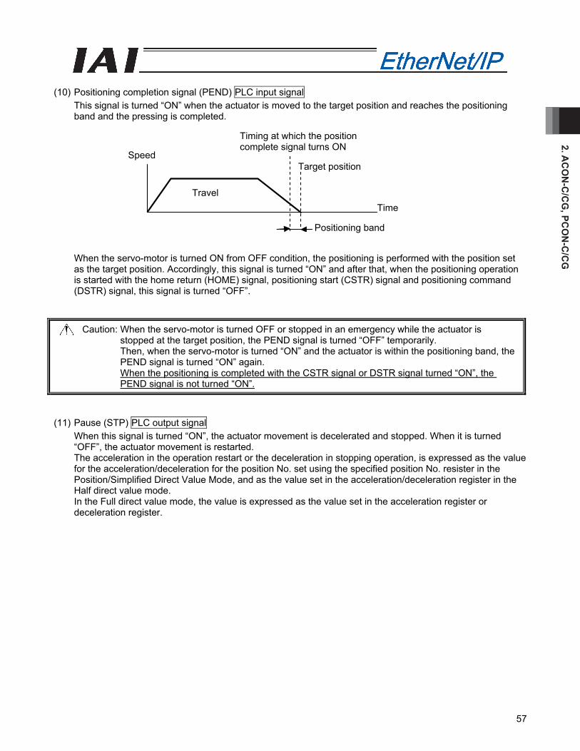
2. AC
ON
-C/C
G, PC
ON
-C/C
G
57
Travel
Speed
Positioning band
Time
Target position
Timing at which the position complete signal turns ON
(10) Positioning completion signal (PEND) PLC input signal
This signal is turned “ON” when the actuator is moved to the target position and reaches the positioning band and the pressing is completed.
When the servo-motor is turned ON from OFF condition, the positioning is performed with the position set as the target position. Accordingly, this signal is turned “ON” and after that, when the positioning operation is started with the home return (HOME) signal, positioning start (CSTR) signal and positioning command (DSTR) signal, this signal is turned “OFF”.
Caution: When the servo-motor is turned OFF or stopped in an emergency while the actuator is stopped at the target position, the PEND signal is turned “OFF” temporarily. Then, when the servo-motor is turned “ON” and the actuator is within the positioning band, the PEND signal is turned “ON” again. When the positioning is completed with the CSTR signal or DSTR signal turned “ON”, the PEND signal is not turned “ON”.
(11) Pause (STP) PLC output signal
When this signal is turned “ON”, the actuator movement is decelerated and stopped. When it is turned “OFF”, the actuator movement is restarted. The acceleration in the operation restart or the deceleration in stopping operation, is expressed as the value for the acceleration/deceleration for the position No. set using the specified position No. resister in the Position/Simplified Direct Value Mode, and as the value set in the acceleration/deceleration register in the Half direct value mode. In the Full direct value mode, the value is expressed as the value set in the acceleration register or deceleration register.

2. A
CO
N-C
/CG
, PC
ON
-C/C
G
58
Zone signal
+ direction Actuator operation Home
Zone setting - Zone setting +
(12) Zone 1 (ZONE1) PLC input signal
Zone 2 (ZONE2) PLC input signal Position zone (PZONE) PLC input signal These signals are turned ON when the current position of the actuator is within the set area and turned OFF when the current position is out of the set area. [1] Zone 1, Zone 2 The zone is set using the user parameters. The Zone 1 Signal is set using the parameter No. 1 “Zone Boundary 1 “+” Side” and No. 2 “Zone Boundary 1 “–“ Side”. The Zone 2 Signal is set using the parameter No. 23 “Zone Boundary 2 “+” Side” and No. 24 “Zone Boundary 2 “–“ Side”. The Zone 1 Signal and Zone 2 Signal become effective when the home return operation is completed. After that, even during the servo OFF, it is effective. [2] Position zone Each zone is set in the position table or using the zone boundary resister. In the case of the Position/Simplified Direct Value Mode, the PZONE signal is set using the position table. In the case of the Full direct value mode, the PZONE signal is set using the Zone Boundary Value Register. (*) In the half direct value mode, there is no PZONE signal. The PZONE signal becomes effective with the movement command after the home return operation. After that, even during the servo OFF, it is effective.

2. AC
ON
-C/C
G, PC
ON
-C/C
G
59
(13) +Jog (JOG+) PLC output signal
–Jog (JOG–) PLC output signal This signal is the command for the jog operation startup or inching operation startup. If a + command is issued, the actuator will operate in the direction opposite home. When a – command is issued, the actuator will operate in the direction of home. [1] Jog operation Jog operation can be performed when the jog/inch switching (JISL) signal is OFF. While the “JOG+” is turned “ON”, the movement direction is to the opposite of the home and when it is turned “OFF”, the actuator is decelerated and stopped. While the JOG – is ON, the actuator will operate in the direction of home and when it is turned OFF, it is decelerated to a stop. The operation is performed based on the set values of the following parameters. • The speed is based on the parameter value specified using the Jog Speed/Inching Distance
Change-Over (JVEL) signal. If the JVEL signal is OFF, the actuator operates according to parameter No. 26, “PIO jog speed”. If the JVEL signal is ON, the actuator operates according to parameter No. 47, “PIO jog speed 2”.
• The acceleration/deceleration conforms to the rate acceleration/deceleration (the specific value varies depending on the actuator).
• When both the JOG+ and JOG- signals are turned “ON”, the actuator is decelerated and stopped. [2] Inch operation The inching operation is available while the JISL signal is turned “ON”. Once it is turned “ON”, the actuator is moved as much as the inching distance. When the JOG+ is turned “ON”, the movement is to the opposite of the home and when the JOG- is turned “ON”, the movement is to the home. The operation is performed based on the set values of the following parameters. • The speed conforms to the value of the parameter specified by the JVEL signal.
If the JVEL signal is OFF, the actuator operates according to parameter No. 26, “PIO jog speed”. If the JVEL signal is ON, the actuator operates according to parameter No. 47, “PIO jog speed 2”.
• The travel conforms to the value of the parameter specified by the JVEL signal. If the JVEL signal is OFF, the actuator operates according to parameter No. 48, “PIO inch distance”. If the JVEL signal is ON, the actuator operates according to parameter No. 49, “PIO inch distance 2”.
• The Acceleration/deceleration is based on the rated acceleration/deceleration (depending on the actuator).
During the normal operation, even when the “+” Jog Signal or “-“ Jog Signal is turned “ON”, the normal operation is continued. (The Jog signal is ignored) In the pause condition, even when the “+” Jog Signal or “-“ Jog Signal is turned “ON”, the actuator is not moved.
(Note) Because the software stroke limit is disabled before the home return operation, the actuator might
run against the mechanism end. Take the greatest care.

2. A
CO
N-C
/CG
, PC
ON
-C/C
G
60
(14) Jog-speed/inch-distance switching (JVEL) PLC output signal
This change-over signal is used for the parameters specifying the jog speed when the jog operation is selected or the inching distance when the inching operation is selected. The relationship is as follows.
JVEL signal Jog operation: JISL=OFF Inch operation: JISL=ON
OFF Parameter No. 26, “Jog speed” Parameter No. 26, “Jog speed” Parameter No. 48, “Inch distance”
ON Parameter No. 47, “Jog speed 2” Parameter No. 47, “Jog speed 2” Parameter No. 49, “Inch distance 2”
(15) Jog/inch switching (JISL) PLC output signal
This signal changes over the jog operation and the inching operation. JISL=OFF: Jog operation JISL=ON : Inch operation When the JISL signal is turned “ON” (for inching operation) during the jog operation, the actuator is decelerated and performs the inching operation. When the JISL signal is turned OFF (jog) while the actuator is moving by inching, the actuator will complete the movement and then switch to the jog function. The table below summarizes the relationship of the ON/OFF statuses of the JISL signal and jog speed/inch-distance switching (JVEL) signal.
Jog operation Inch operation
JISL OFF ON Speed Parameter No. 26, “Jog speed” Parameter No. 26, “Jog speed” Travel – Parameter No. 48, “Inch distance”
JVEL=OFF Acceleration/deceleration
Rated value (The specific value varies depending on the actuator.)
Rated value (The specific value varies depending on the actuator.)
Speed Parameter No. 47, “Jog speed 2” Parameter No. 47, “Jog speed 2” Travel – Parameter No. 49, “Inch distance 2”
JVEL=ON Acceleration/deceleration
Rated value (The specific value varies depending on the actuator.)
Rated value (The specific value varies depending on the actuator.)
Operation When the JOG +/JOG – signal is ON.
Upon detection of the leading (ON) edge of the JOG +/JOG – signal.

2. AC
ON
-C/C
G, PC
ON
-C/C
G
61
(16) Teaching mode command (MODE) PLC output signal
Teaching mode signal (MODES) PLC input signal When the MODE signal is turned “ON”, the normal operation mode is changed to the teaching mode. When the mode for the controllers for each actuator is changed to the teaching mode, the MODES signal is turned ON. After confirming that the MODES signal is turned “ON” on the PLC side, start the teaching operation. (Note) In order to change the normal operation mode to the teaching mode, the following conditions are
required. • The actuator operation (motor) is stopped. • The + JOG (JOG+) signal and – JOG (JOG-) signal are turned “OFF”. • The Position Data Import Command (PWRT) Signal and Positioning start (CSTR) Signal are turned
“OFF”. (Note) When the PWRT signal is not turned OFF, the mode is not returned to the normal operation mode.
(17) Position data import command (PWRT) PLC output signal
Position data import complete (WEND) PLC input signal The PWRT signal is available when the teaching mode signal (MODES) is turned “ON”. Turn the PWRT signal ON (*1), and the data of the current position will be written to the “Position” field under the position number set to the specified position number resister of the PLC (*2). When the data writing is completed, the WEND signal is turned “ON”. After the WEND signal is turned ON, turn OFF the PWRT signal in the host machine. When the PWRT signal is turned ON before the WEND signal is turned “ON”, the WEND signal is not turned “ON”. When the PWRT signal is turned “OFF” the WEND signal is also turned “OFF”. (*1) Turn it on for 20msec or more. If the time is shorter than 20msec, the writing is not completed. (*2) When the data items except for the position have not been defined, the parameter initial values are
written. (Refer to the operation manual for the controller main body) (18) Forced brake release (BKRL) PLC output signal
Turning this signal “ON” can release the brake forcibly.
(ACON, PCON → PLC) 20 msec or more
(PLC → ACON, PCON)
(ACON, PCON → PLC)
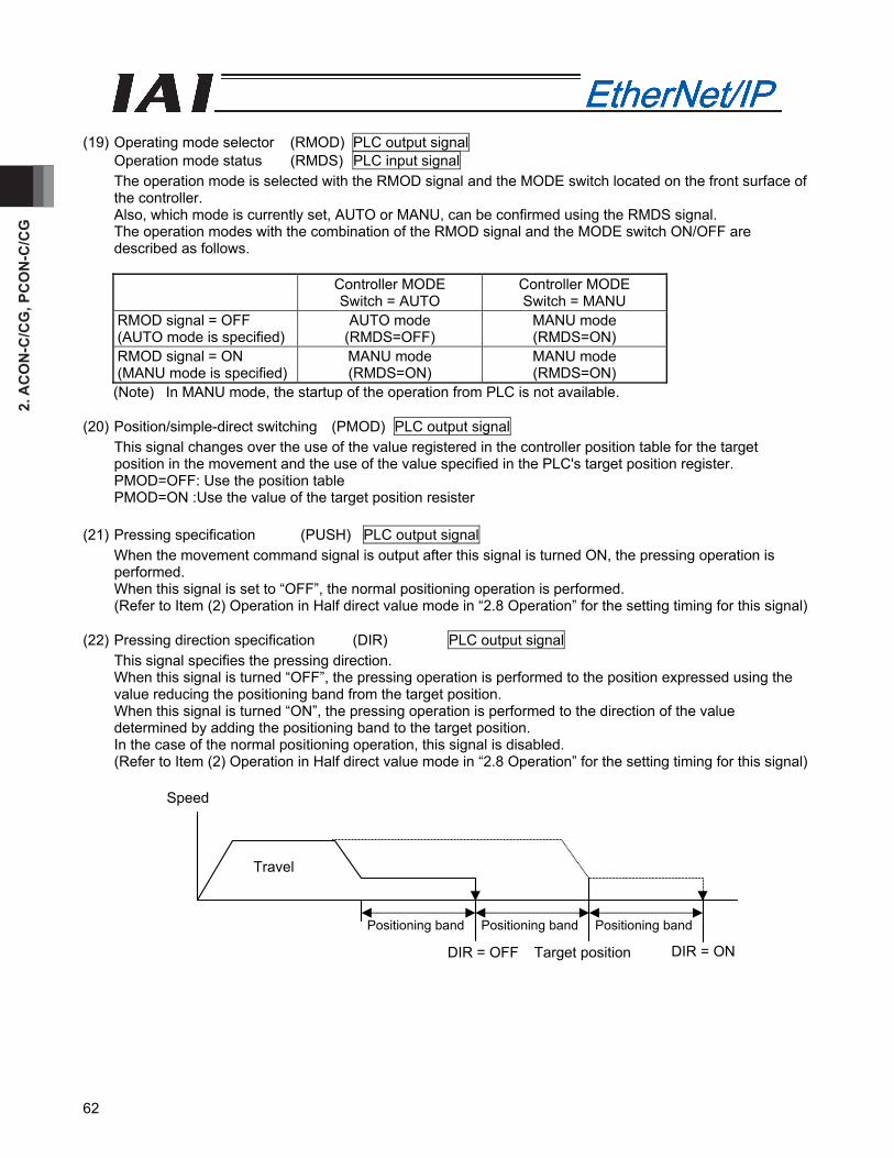
2. A
CO
N-C
/CG
, PC
ON
-C/C
G
62
Speed
Travel
Positioning band Positioning band Positioning band
DIR = OFF Target position DIR = ON
(19) Operating mode selector (RMOD) PLC output signal
Operation mode status (RMDS) PLC input signal The operation mode is selected with the RMOD signal and the MODE switch located on the front surface of the controller. Also, which mode is currently set, AUTO or MANU, can be confirmed using the RMDS signal. The operation modes with the combination of the RMOD signal and the MODE switch ON/OFF are described as follows.
Controller MODE Switch = AUTO
Controller MODE Switch = MANU
RMOD signal = OFF (AUTO mode is specified)
AUTO mode (RMDS=OFF)
MANU mode (RMDS=ON)
RMOD signal = ON (MANU mode is specified)
MANU mode (RMDS=ON)
MANU mode (RMDS=ON)
(Note) In MANU mode, the startup of the operation from PLC is not available. (20) Position/simple-direct switching (PMOD) PLC output signal
This signal changes over the use of the value registered in the controller position table for the target position in the movement and the use of the value specified in the PLC's target position register. PMOD=OFF: Use the position table PMOD=ON :Use the value of the target position resister
(21) Pressing specification (PUSH) PLC output signal
When the movement command signal is output after this signal is turned ON, the pressing operation is performed. When this signal is set to “OFF”, the normal positioning operation is performed. (Refer to Item (2) Operation in Half direct value mode in “2.8 Operation” for the setting timing for this signal)
(22) Pressing direction specification (DIR) PLC output signal This signal specifies the pressing direction. When this signal is turned “OFF”, the pressing operation is performed to the position expressed using the value reducing the positioning band from the target position. When this signal is turned “ON”, the pressing operation is performed to the direction of the value determined by adding the positioning band to the target position. In the case of the normal positioning operation, this signal is disabled. (Refer to Item (2) Operation in Half direct value mode in “2.8 Operation” for the setting timing for this signal)
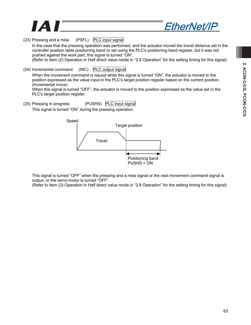
2. AC
ON
-C/C
G, PC
ON
-C/C
G
63
(23) Pressing and a miss (PSFL) PLC input signal
In the case that the pressing operation was performed, and the actuator moved the travel distance set in the controller position table positioning band or set using the PLC's positioning band register, but it was not pushed against the work part, this signal is turned “ON”. (Refer to Item (2) Operation in Half direct value mode in “2.8 Operation” for the setting timing for this signal)
(24) Incremental command (INC) PLC output signal
When the movement command is issued while this signal is turned “ON”, the actuator is moved to the position expressed as the value input in the PLC's target position register based on the current position. (Incremental move) When this signal is turned “OFF”, the actuator is moved to the position expressed as the value set in the PLC's target position register.
(25) Pressing in progress (PUSHS) PLC input signal
This signal is turned “ON” during the pressing operation.
This signal is turned “OFF” when the pressing and a miss signal or the next movement command signal is output, or the servo-motor is turned “OFF”. (Refer to Item (2) Operation in Half direct value mode in “2.8 Operation” for the setting timing for this signal)
Speed
Travel
Target position
Positioning band PUSHS = ON
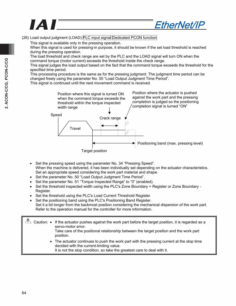
2. A
CO
N-C
/CG
, PC
ON
-C/C
G
64
(26) Load output judgment (LOAD) PLC input signal Dedicated PCON function
This signal is available only in the pressing operation. When this signal is used for pressing-in purpose, it should be known if the set load threshold is reached during the pressing operation. The load threshold and check range are set by the PLC and the LOAD signal will turn ON when the command torque (motor current) exceeds the threshold inside the check range. This signal judges the load output based on the fact that the command torque exceeds the threshold for the specified time period. This processing procedure is the same as for the pressing judgment. The judgment time period can be changed freely using the parameter No. 50 “Load Output Judgment Time Period”. This signal is continued until the next movement command is received.
• Set the pressing speed using the parameter No. 34 “Pressing Speed”. When the machine is delivered, it has been individually set depending on the actuator characteristics. Set an appropriate speed considering the work part material and shape.
• Set the parameter No. 50 “Load Output Judgment Time Period”. • Set the parameter No. 51 “Torque Inspected Range” to “0” (enabled). • Set the threshold inspected width using the PLC's Zone Boundary + Register or Zone Boundary -
Register. • Set the threshold using the PLC's Load Current Threshold Register. • Set the positioning band using the PLC's Positioning Band Register.
Set it a bit longer from the backmost position considering the mechanical dispersion of the work part. Refer to the operation manual for the controller for more information.
Caution: • If the actuator pushes against the work part before the target position, it is regarded as a servo-motor error. Take care of the positional relationship between the target position and the work part position.
• The actuator continues to push the work part with the pressing current at the stop time decided with the current-limiting value. It is not the stop condition, so take the greatest care to deal with it.
Position where this signal is turned ON when the command torque exceeds the threshold within the torque inspected width range
Crack rangeSpeed
Travel
Target position
Position where the actuator is pushed against the work part and the pressing completion is judged so the positioning completion signal is turned “ON”
Positioning band (max. pressing level)
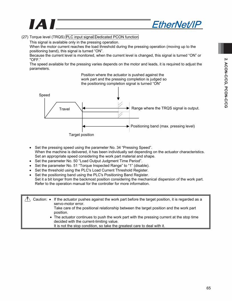
2. AC
ON
-C/C
G, PC
ON
-C/C
G
65
Target position
Travel
Speed
Position where the actuator is pushed against the work part and the pressing completion is judged so the positioning completion signal is turned “ON”
Range where the TRQS signal is output.
Positioning band (max. pressing level)
(27) Torque level (TRQS) PLC input signal Dedicated PCON function
This signal is available only in the pressing operation. When the motor current reaches the load threshold during the pressing operation (moving up to the positioning band), this signal is turned “ON”. Because the current level is monitored, when the current level is changed, this signal is turned “ON” or "OFF.” The speed available for the pressing varies depends on the motor and leads, it is required to adjust the parameters.
• Set the pressing speed using the parameter No. 34 “Pressing Speed”. When the machine is delivered, it has been individually set depending on the actuator characteristics. Set an appropriate speed considering the work part material and shape.
• Set the parameter No. 50 “Load Output Judgment Time Period”. • Set the parameter No. 51 “Torque Inspected Range” to “1” (disable). • Set the threshold using the PLC's Load Current Threshold Register. • Set the positioning band using the PLC's Positioning Band Register.
Set it a bit longer from the backmost position considering the mechanical dispersion of the work part. Refer to the operation manual for the controller for more information.
Caution: • If the actuator pushes against the work part before the target position, it is regarded as a servo-motor error. Take care of the positional relationship between the target position and the work part position.
• The actuator continues to push the work part with the pressing current at the stop time decided with the current-limiting value. It is not the stop condition, so take the greatest care to deal with it.

2. A
CO
N-C
/CG
, PC
ON
-C/C
G
66
(28) Stopping control mode (SMOD) PLC output signal Dedicated PCON function
One of the pulse motor general characteristics is that that the holding current in the stop mode is larger than that for the AC servo-motor. Because of this, when the stop time is longer at the standby position, the measure to reduce the power consumption at the stop mode is taken as one of the energy saving measures. SMOD=ON: Full Servo Control System is used in the standby condition. SMOD=OFF: Standby condition
• Full-servo control mode
By means of servo control of the pulse motor, the holding current can be reduced. The reduction level varies depending on the actuator type or load conditions. However, generally, the holding current will be 1/2 to 1/4. The actual holding current can be confirmed in the current monitor window in the PC software. (Note) Under the condition where any external force is given or depending on the stop position, slight
vibration or abnormal noise might be caused.
Before implementing this feature, take care to investigate its effects on the whole system in a controlled manner.
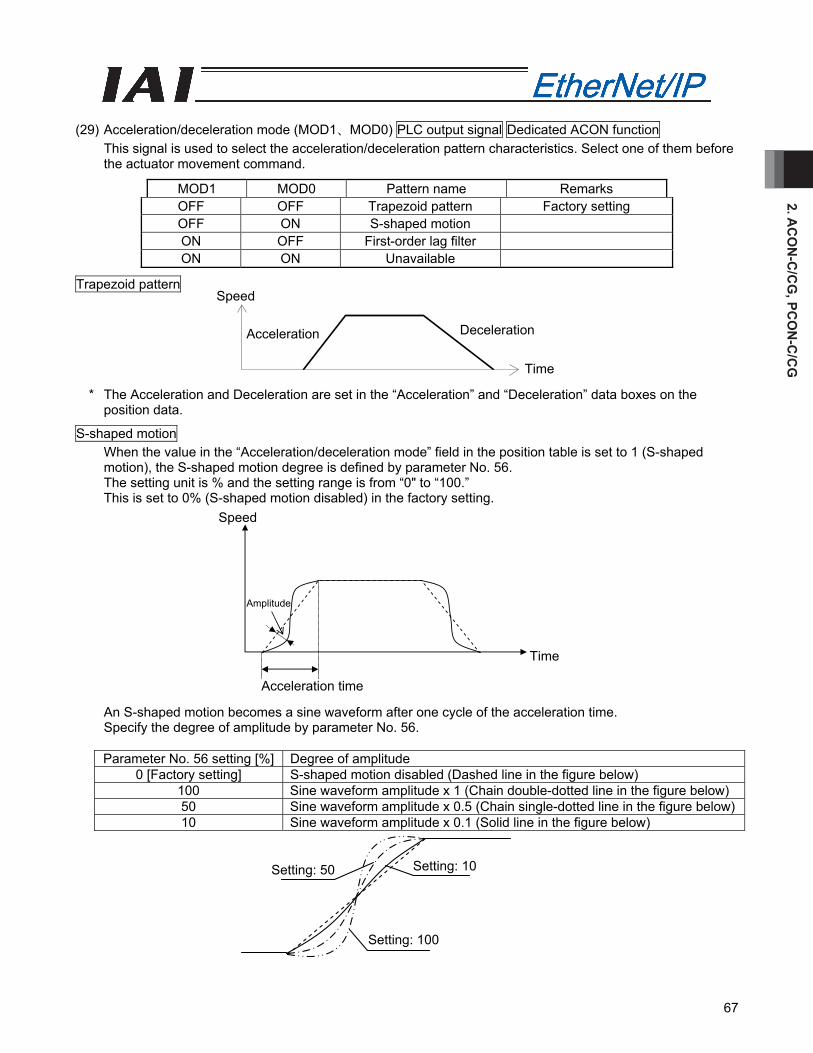
2. AC
ON
-C/C
G, PC
ON
-C/C
G
67
Setting: 50
Setting: 100
Setting: 10
(29) Acceleration/deceleration mode (MOD1、MOD0) PLC output signal Dedicated ACON function
This signal is used to select the acceleration/deceleration pattern characteristics. Select one of them before the actuator movement command.
MOD1 MOD0 Pattern name Remarks OFF OFF Trapezoid pattern Factory setting OFF ON S-shaped motion ON OFF First-order lag filter ON ON Unavailable
Trapezoid pattern
* The Acceleration and Deceleration are set in the “Acceleration” and “Deceleration” data boxes on the position data.
S-shaped motion When the value in the “Acceleration/deceleration mode” field in the position table is set to 1 (S-shaped motion), the S-shaped motion degree is defined by parameter No. 56. The setting unit is % and the setting range is from “0" to “100.” This is set to 0% (S-shaped motion disabled) in the factory setting.
An S-shaped motion becomes a sine waveform after one cycle of the acceleration time. Specify the degree of amplitude by parameter No. 56.
Parameter No. 56 setting [%] Degree of amplitude
0 [Factory setting] S-shaped motion disabled (Dashed line in the figure below) 100 Sine waveform amplitude x 1 (Chain double-dotted line in the figure below) 50 Sine waveform amplitude x 0.5 (Chain single-dotted line in the figure below)10 Sine waveform amplitude x 0.1 (Solid line in the figure below)
Speed
Acceleration Deceleration
Time
Speed
Time
Acceleration time
Amplitude
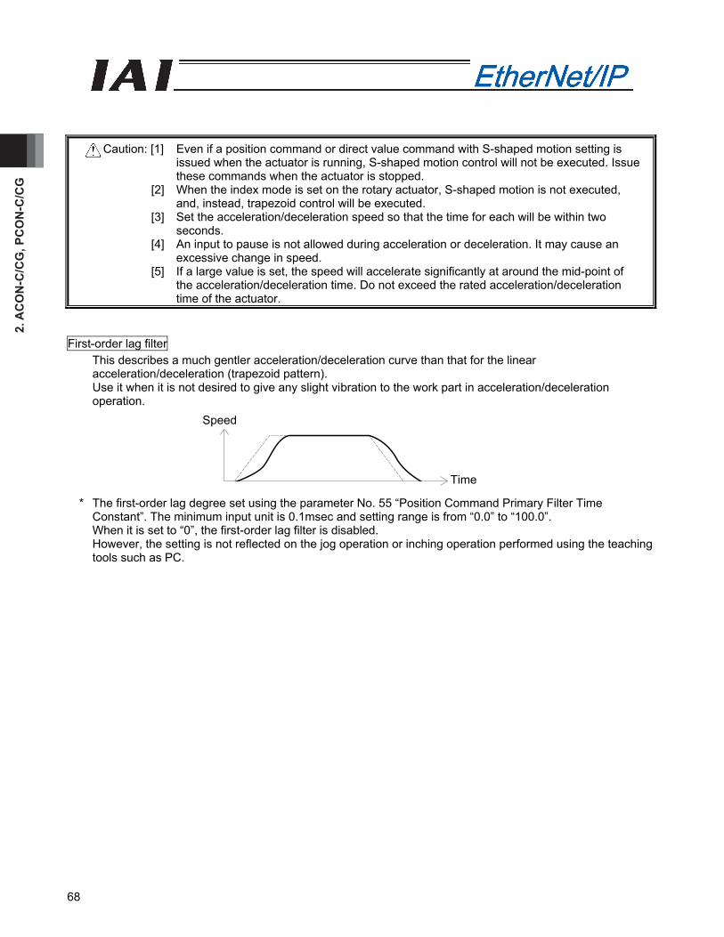
2. A
CO
N-C
/CG
, PC
ON
-C/C
G
68
Caution: [1] Even if a position command or direct value command with S-shaped motion setting is issued when the actuator is running, S-shaped motion control will not be executed. Issue these commands when the actuator is stopped.
[2] When the index mode is set on the rotary actuator, S-shaped motion is not executed, and, instead, trapezoid control will be executed.
[3] Set the acceleration/deceleration speed so that the time for each will be within two seconds.
[4] An input to pause is not allowed during acceleration or deceleration. It may cause an excessive change in speed.
[5] If a large value is set, the speed will accelerate significantly at around the mid-point of the acceleration/deceleration time. Do not exceed the rated acceleration/deceleration time of the actuator.
First-order lag filter This describes a much gentler acceleration/deceleration curve than that for the linear acceleration/deceleration (trapezoid pattern). Use it when it is not desired to give any slight vibration to the work part in acceleration/deceleration operation.
* The first-order lag degree set using the parameter No. 55 “Position Command Primary Filter Time Constant”. The minimum input unit is 0.1msec and setting range is from “0.0” to “100.0”. When it is set to “0”, the first-order lag filter is disabled. However, the setting is not reflected on the jog operation or inching operation performed using the teaching tools such as PC.
Speed
Time
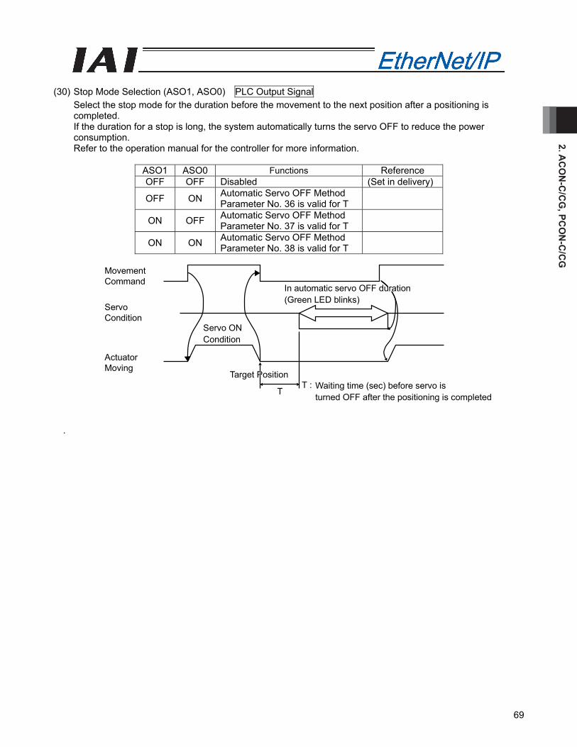
2. AC
ON
-C/C
G, PC
ON
-C/C
G
69
(30) Stop Mode Selection (ASO1, ASO0) PLC Output Signal
Select the stop mode for the duration before the movement to the next position after a positioning is completed. If the duration for a stop is long, the system automatically turns the servo OFF to reduce the power consumption. Refer to the operation manual for the controller for more information.
ASO1 ASO0 Functions Reference OFF OFF Disabled (Set in delivery)
OFF ON Automatic Servo OFF Method Parameter No. 36 is valid for T
ON OFF Automatic Servo OFF Method Parameter No. 37 is valid for T
ON ON Automatic Servo OFF Method Parameter No. 38 is valid for T
T :T
MovementCommand
ActuatorMoving
Target Position
ServoCondition
In automatic servo OFF duration(Green LED blinks)
Servo ONCondition
Waiting time (sec) before servo isturned OFF after the positioning is completed
.

2. A
CO
N-C
/CG
, PC
ON
-C/C
G
70
PLC sequence programControl signal
Status signal
ACON, PCONControl signal
Status signal
Master station → Slave transmission delay time (Yt)
Slave → Master station Transmission delay time (Xt)
Command processing time
2.7 I/O Signal Timings
When any of the control signal is turned ON to perform the operation of the robot cylinder using the PLC's sequence program, the response (status) is returned to the PLC. The maximum response time is expressed using the following formula.
Maximum response time (msec)=Yt+Xt+3+ command processing time (operation time, etc.)
Yt: Master station→slave transmission delay time Xt: Slave→master station transmission delay time
Master Station → For the master station → slave transmission delay (Yt) and slave →master station
transmission delay (Xt), refer to the operation manuals for the EtherNet/IP master unit and PLC installed in the master unit.
Filed network transmission delay time
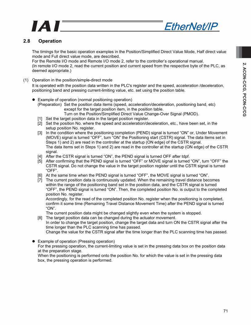
2. AC
ON
-C/C
G, PC
ON
-C/C
G
71
2.8 Operation
The timings for the basic operation examples in the Position/Simplified Direct Value Mode, Half direct value mode and Full direct value mode, are described. For the Remote I/O mode and Remote I/O mode 2, refer to the controller’s operational manual. (In remote I/O mode 2, read the current position and current speed from the respective byte of the PLC, as deemed appropriate.)
(1) Operation in the position/simple-direct mode
It is operated with the position data written in the PLC's register and the speed, acceleration /deceleration, positioning band and pressing current-limiting value, etc. set using the position table.
Example of operation (normal positioning operation)
(Preparation) Set the position data items (speed, acceleration/deceleration, positioning band, etc) except for the target position item, in the position table. Turn on the Position/Simplified Direct Value Change-Over Signal (PMOD).
[1] Set the target position data in the target position register. [2] Set the position No. where the speed and acceleration/deceleration, etc., have been set, in the
setup position No. register. [3] In the condition where the positioning completion (PEND) signal is turned “ON” or, Under Movement
(MOVE) signal is turned “OFF”, turn “ON” the Positioning start (CSTR) signal. The data items set in Steps 1) and 2) are read in the controller at the startup (ON edge) of the CSTR signal. The data items set in Steps 1) and 2) are read in the controller at the startup (ON edge) of the CSTR signal.
[4] After the CSTR signal is turned “ON”, the PEND signal is turned OFF after tdpf. [5] After confirming that the PEND signal is turned “OFF” or MOVE signal is turned “ON”, turn “OFF” the
CSTR signal. Do not change the value in the target position register until the CSTR signal is turned “OFF”.
[6] At the same time when the PEND signal is turned “OFF”, the MOVE signal is turned “ON”. [7] The current position data is continuously updated. When the remaining travel distance becomes
within the range of the positioning band set in the position data, and the CSTR signal is turned “OFF”, the PEND signal is turned “ON”. Then, the completed position No. is output to the completed position No. register. Accordingly, for the read of the completed position No. register when the positioning is completed, confirm it some time (Remaining Travel Distance Movement Time) after the PEND signal is turned “ON”. The current position data might be changed slightly even when the system is stopped.
[8] The target position data can be changed during the actuator movement. In order to change the target position, change the target data and turn ON the CSTR signal after the time longer than the PLC scanning time has passed. Change the value for the CSTR signal after the time longer than the PLC scanning time has passed.
Example of operation (Pressing operation)
For the pressing operation, the current-limiting value is set in the pressing data box on the position data at the preparation stage. When the positioning is performed onto the position No. for which the value is set in the pressing data box, the pressing operation is performed.
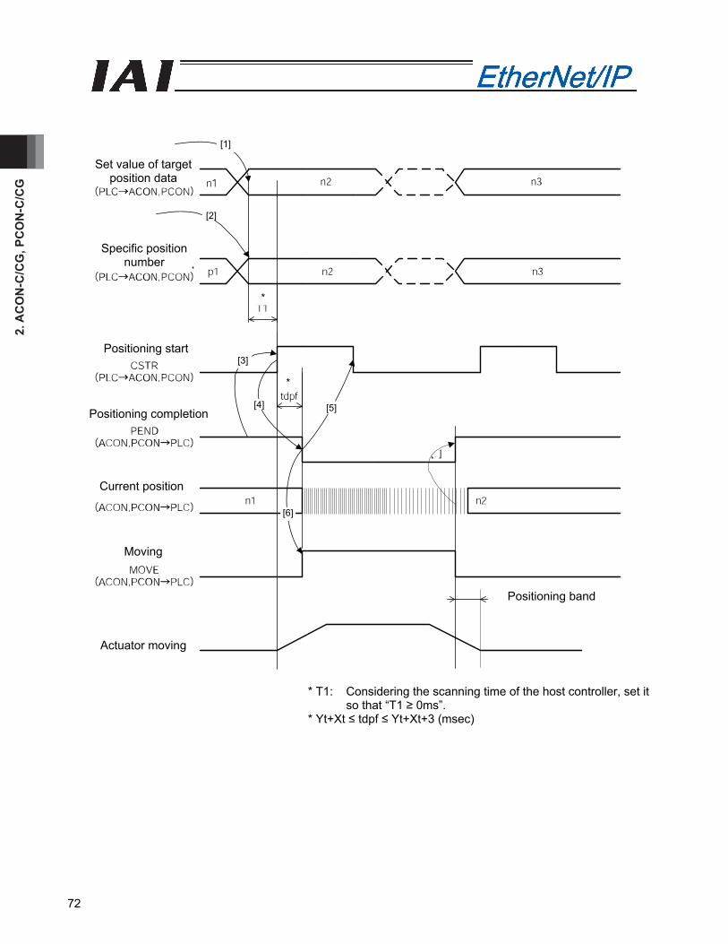
2. A
CO
N-C
/CG
, PC
ON
-C/C
G
72
* T1: Considering the scanning time of the host controller, set it so that “T1 ≥ 0ms”.
* Yt+Xt ≤ tdpf ≤ Yt+Xt+3 (msec)
[7]
[1]
[2]
[3]
[4] [5]
[6]
*
Set value of target position data
Specific position number
Positioning start
Positioning completion
Current position
Moving
*
Positioning band
Actuator moving

2. AC
ON
-C/C
G, PC
ON
-C/C
G
73
(2) Operation in the half direction mode
It is operated with the data set in the PLC's target position register, positioning band register, setup speed register, acceleration/deceleration register and pressing current-limiting setup register.
Example of operation (Pressing operation) [1] Set the target position data in the target position register. [2] Set the positioning band data in the positioning band register. [3] Set the speed data to the speed resister. [4] Set the acceleration/deceleration data to the acceleration/deceleration resister. [5] Set the pressing current-limiting data in the pressing current-limiting value register. [6] Turn “ON” the pressing setup (PUSH) signal. [7] Specify the pressing direction using the pressing direction setup (DIR) signal. (refer to 2.6.7 (22)) [8] In the condition where the positioning completion (PEND) signal is turned “ON” or under movement
signal (MOVE) is turned “OFF”, turn “ON” the positioning command (DSTR) signal. The data items set in Steps 1) through 5) are read in the controller at the startup (ON edge) of the DSTR signal.
[9] After the DSTR signal is turned “ON”, the PEND signal is turned “OFF” after tdpf. [10] After confirming that the PEND signal is turned “OFF” or the MOVE signal is turned “ON”, turn “OFF”
the DSTR signal. Do not change any value in each register until the DSTR signal has been turned “OFF”.
[11] At the same time when the PEND signal is turned “OFF”, the MOVE signal is turned “ON”. [12] The current position data is continuously updated. [13] When the DSTR signal is turned “OFF” and the motor current reaches the current-limiting value set
in Step 5, the PEND signal is turned “ON”. (Completion of pressing operation) Even when the positioning band set in Step 2 is reached, in the case that the current does not reach the motor current-limiting value set in Step 5, the pressing and a miss (PSFL) signal is turned "ON”. In this case, the PEND signal is not turned “ON” (Pressing and a Miss).
[14] After the PEND signal or PSFL signal is turned “ON”, turn “OFF” the PUSH signal.
Example of operation (normal positioning operation) For the general positioning operation, set the signal in Step 6 to “OFF”. When the remaining travel distance becomes within the range of the positioning band set in the position data, and the DSTR signal is turned “OFF”, the PEND signal is turned “ON”.
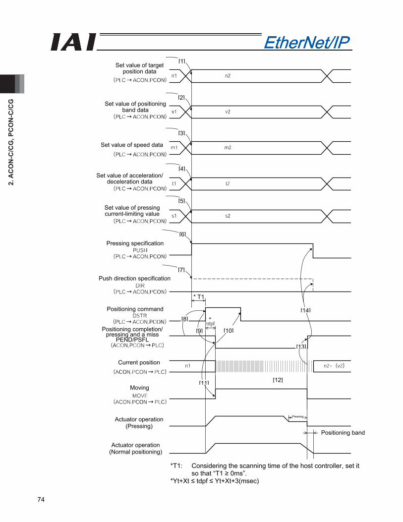
2. A
CO
N-C
/CG
, PC
ON
-C/C
G
74
*T1: Considering the scanning time of the host controller, set it so that “T1 ≥ 0ms”.
*Yt+Xt ≤ tdpf ≤ Yt+Xt+3(msec)
Positioning band
[1]
[2]
[3]
[4]
[5]
[6]
[7]
[8]
[9] [10]
[11] [12]
[14]
[13]
Set value of target position data
Set value of positioning band data
Set value of speed data
*
Set value of acceleration/deceleration data
Set value of pressing current-limiting value
Pressing specification
Push direction specification
Positioning command
Positioning completion/pressing and a miss
PEND/PSFL
Current position
Moving
Actuator operation (Pressing)
Actuator operation (Normal positioning)
* T1
Pressing
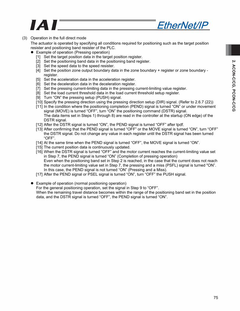
2. AC
ON
-C/C
G, PC
ON
-C/C
G
75
(3) Operation in the full direct mode
The actuator is operated by specifying all conditions required for positioning such as the target position resister and positioning band resister of the PLC.
Example of operation (Pressing operation) [1] Set the target position data in the target position register. [2] Set the positioning band data in the positioning band register. [3] Set the speed data to the speed resister. [4] Set the position zone output boundary data in the zone boundary + register or zone boundary -
register. [5] Set the acceleration data in the acceleration register. [6] Set the deceleration data in the deceleration register. [7] Set the pressing current-limiting data in the pressing current-limiting value register. [8] Set the load current threshold data in the load current threshold setup register. [9] Turn “ON” the pressing setup (PUSH) signal. [10] Specify the pressing direction using the pressing direction setup (DIR) signal. (Refer to 2.6.7 (22)) [11] In the condition where the positioning completion (PEND) signal is turned “ON” or under movement
signal (MOVE) is turned “OFF”, turn “ON” the positioning command (DSTR) signal. The data items set in Steps 1) through 8) are read in the controller at the startup (ON edge) of the DSTR signal.
[12] After the DSTR signal is turned “ON”, the PEND signal is turned “OFF” after tpdf. [13] After confirming that the PEND signal is turned “OFF” or the MOVE signal is turned “ON”, turn “OFF”
the DSTR signal. Do not change any value in each register until the DSTR signal has been turned “OFF”.
[14] At the same time when the PEND signal is turned “OFF”, the MOVE signal is turned “ON”. [15] The current position data is continuously updated. [16] When the DSTR signal is turned “OFF” and the motor current reaches the current-limiting value set
in Step 7, the PEND signal is turned “ON” (Completion of pressing operation) Even when the positioning band set in Step 2 is reached, in the case that the current does not reach the motor current-limiting value set in Step 7, the pressing and a miss (PSFL) signal is turned "ON”. In this case, the PEND signal is not turned “ON” (Pressing and a Miss).
[17] After the PEND signal or PSEL signal is turned “ON”, turn “OFF” the PUSH signal.
Example of operation (normal positioning operation) For the general positioning operation, set the signal in Step 9 to “OFF”. When the remaining travel distance becomes within the range of the positioning band set in the position data, and the DSTR signal is turned “OFF”, the PEND signal is turned “ON”.
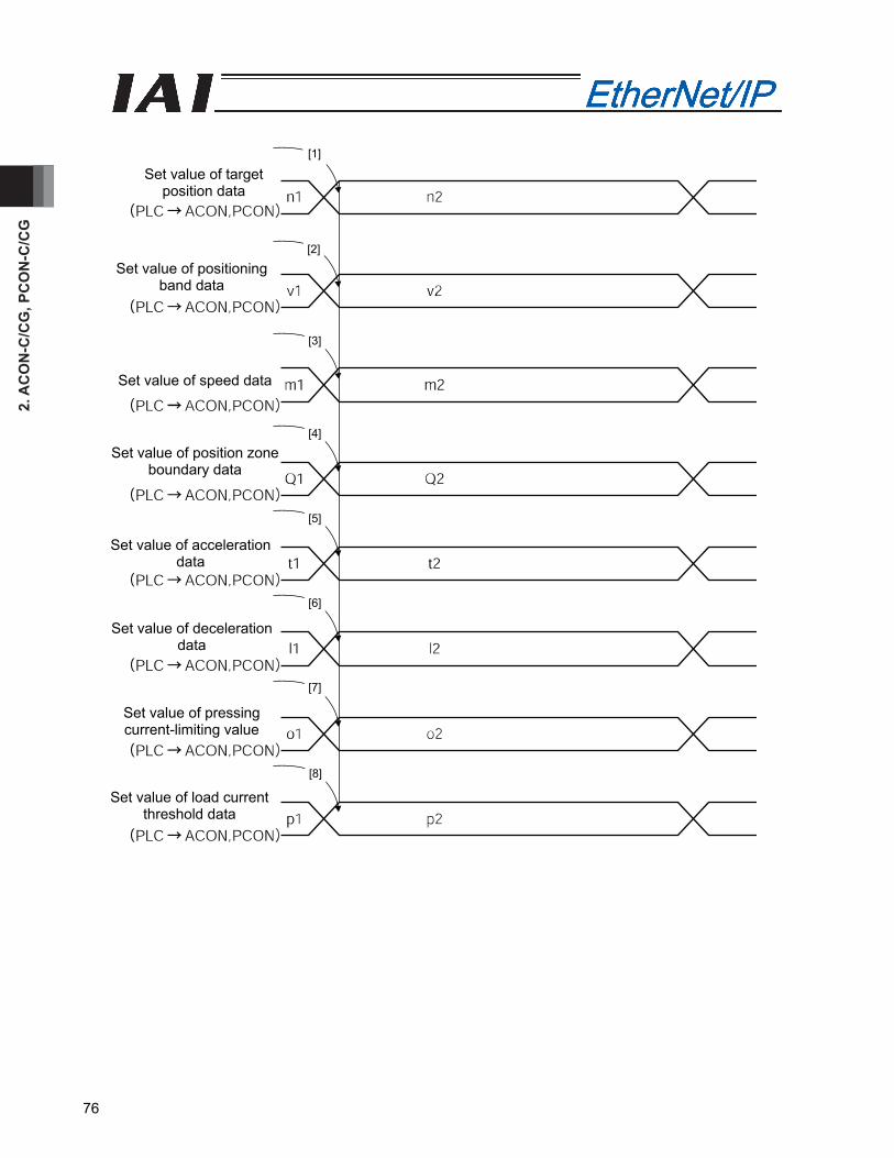
2. A
CO
N-C
/CG
, PC
ON
-C/C
G
76
[1]
[2]
[3]
[4]
[5]
[6]
[7]
[8]
Set value of target position data
Set value of positioning band data
Set value of speed data
Set value of position zone boundary data
Set value of acceleration data
Set value of deceleration data
Set value of pressing current-limiting value
Set value of load current threshold data
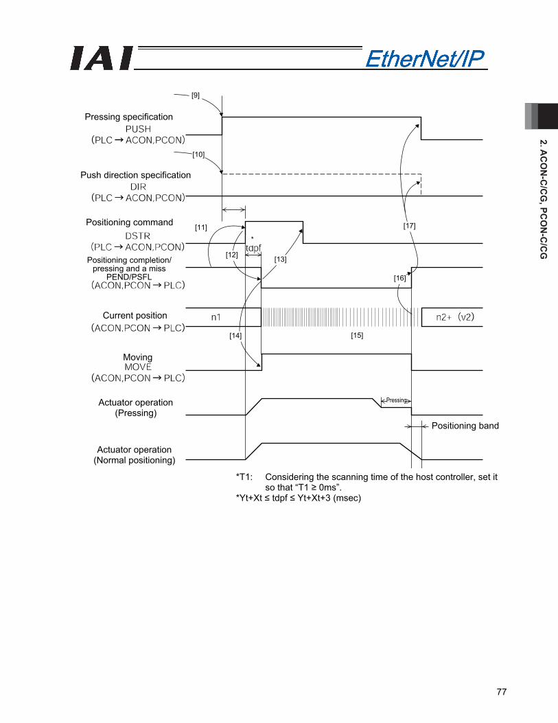
2. AC
ON
-C/C
G, PC
ON
-C/C
G
77
*T1: Considering the scanning time of the host controller, set it so that “T1 ≥ 0ms”.
*Yt+Xt ≤ tdpf ≤ Yt+Xt+3 (msec)
[9]
[10]
[11]
[12] [13]
[17]
[16]
[15][14]
Pressing specification
Push direction specification
Positioning command
Positioning completion/ pressing and a miss
PEND/PSFL
Current position
Moving
Actuator operation (Normal positioning)
Actuator operation (Pressing)
Pressing
*
Positioning band
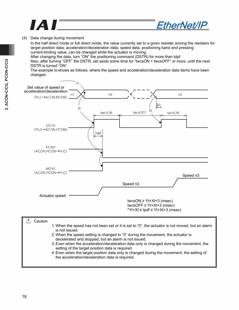
2. A
CO
N-C
/CG
, PC
ON
-C/C
G
78
[1]
[2] [3]
Actuator speed
Speed n2
Speed n3
Set value of speed or acceleration/deceleration
(4) Data change during movement
In the half direct mode or full direct mode, the value currently set to a given resister among the resisters for target position data, acceleration/deceleration data, speed data, positioning band and pressing current-limiting value, can be changed while the actuator is moving. After changing the data, turn “ON” the positioning command (DSTR) for more than tdpf. Also, after turning “OFF” the DSTR, set aside some time for “twcsON + twcsOFF” or more, until the next DSTR is turned “ON”. The example is shows as follows, where the speed and acceleration/deceleration data items have been changed.
twcsON ≥ Yt+Xt+3 (msec) twcsOFF ≥ Yt+Xt+3 (msec) *Yt+Xt ≤ tpdf ≤ Yt+Xt+3 (msec)
Caution 1. When the speed has not been set or it is set to “0”, the actuator is not moved, but an alarm
is not issued. 2. When the speed setting is changed to “0” during the movement, the actuator is
decelerated and stopped, but an alarm is not issued. 3. Even when the acceleration/deceleration data only is changed during the movement, the
setting of the target position data is required. 4. Even when the target position data only is changed during the movement, the setting of
the acceleration/deceleration data is required.
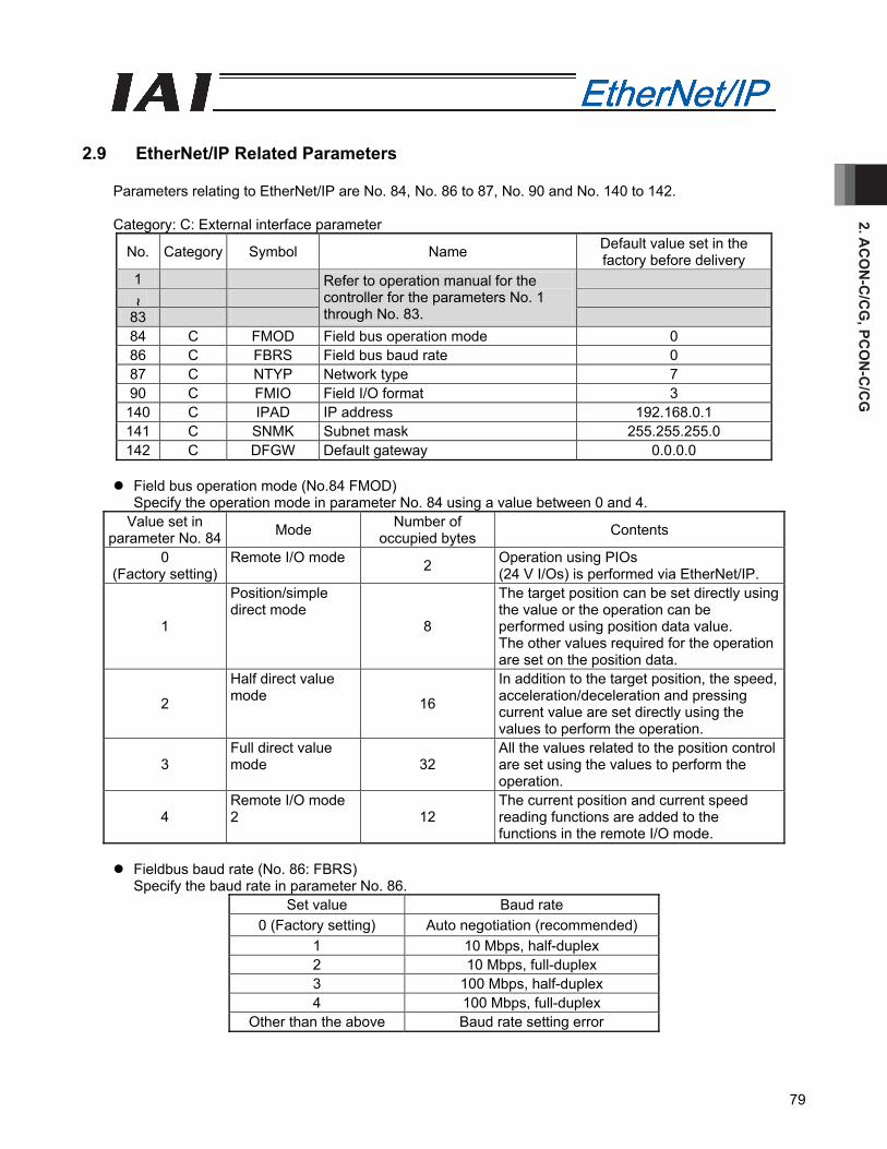
2. AC
ON
-C/C
G, PC
ON
-C/C
G
79
2.9 EtherNet/IP Related Parameters
Parameters relating to EtherNet/IP are No. 84, No. 86 to 87, No. 90 and No. 140 to 142.
Category: C: External interface parameter
No. Category Symbol Name Default value set in the factory before delivery
1
~ 83
Refer to operation manual for the controller for the parameters No. 1 through No. 83.
84 C FMOD Field bus operation mode 0 86 C FBRS Field bus baud rate 0 87 C NTYP Network type 7 90 C FMIO Field I/O format 3 140 C IPAD IP address 192.168.0.1 141 C SNMK Subnet mask 255.255.255.0 142 C DFGW Default gateway 0.0.0.0
Field bus operation mode (No.84 FMOD)
Specify the operation mode in parameter No. 84 using a value between 0 and 4. Value set in
parameter No. 84 Mode Number of occupied bytes Contents
0 (Factory setting)
Remote I/O mode 2 Operation using PIOs (24 V I/Os) is performed via EtherNet/IP.
1
Position/simple direct mode
8
The target position can be set directly using the value or the operation can be performed using position data value. The other values required for the operation are set on the position data.
2
Half direct value mode 16
In addition to the target position, the speed, acceleration/deceleration and pressing current value are set directly using the values to perform the operation.
3 Full direct value mode 32
All the values related to the position control are set using the values to perform the operation.
4 Remote I/O mode 2 12
The current position and current speed reading functions are added to the functions in the remote I/O mode.
Fieldbus baud rate (No. 86: FBRS)
Specify the baud rate in parameter No. 86. Set value Baud rate
0 (Factory setting) Auto negotiation (recommended) 1 10 Mbps, half-duplex 2 10 Mbps, full-duplex 3 100 Mbps, half-duplex 4 100 Mbps, full-duplex
Other than the above Baud rate setting error
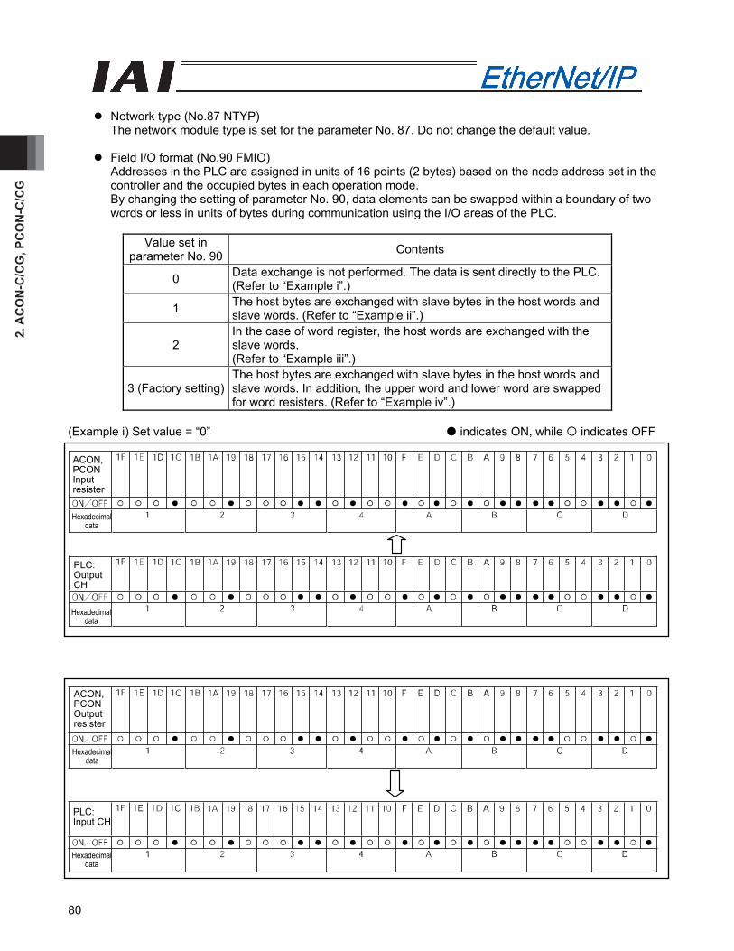
2. A
CO
N-C
/CG
, PC
ON
-C/C
G
80
Network type (No.87 NTYP)
The network module type is set for the parameter No. 87. Do not change the default value.
Field I/O format (No.90 FMIO) Addresses in the PLC are assigned in units of 16 points (2 bytes) based on the node address set in the controller and the occupied bytes in each operation mode. By changing the setting of parameter No. 90, data elements can be swapped within a boundary of two words or less in units of bytes during communication using the I/O areas of the PLC.
Value set in
parameter No. 90 Contents
0 Data exchange is not performed. The data is sent directly to the PLC. (Refer to “Example i”.)
1 The host bytes are exchanged with slave bytes in the host words and slave words. (Refer to “Example ii”.)
2 In the case of word register, the host words are exchanged with the slave words. (Refer to “Example iii”.)
3 (Factory setting) The host bytes are exchanged with slave bytes in the host words and slave words. In addition, the upper word and lower word are swapped for word resisters. (Refer to “Example iv”.)
(Example i) Set value = “0” indicates ON, while indicates OFF
ACON, PCON Input resister
Hexadecimal data
Hexadecimal data
PLC: Output CH
ACON, PCON Output resister
Hexadecimal data
Hexadecimal data
PLC: Input CH
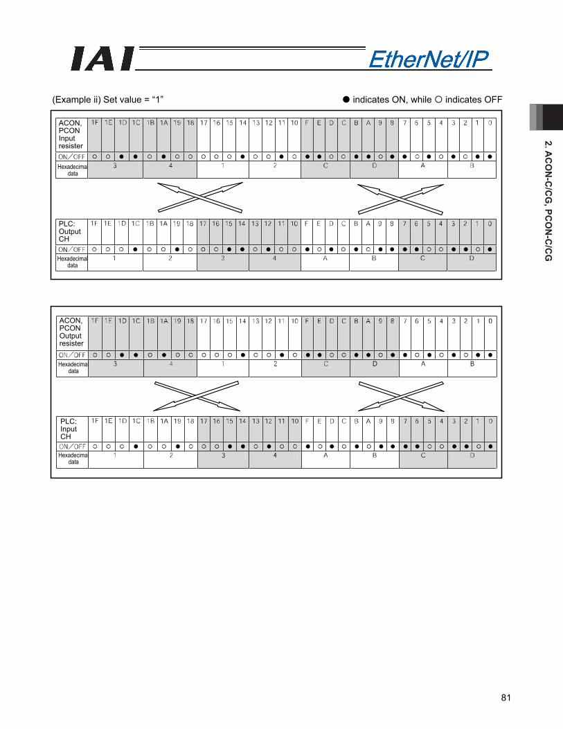
2. AC
ON
-C/C
G, PC
ON
-C/C
G
81
(Example ii) Set value = “1” indicates ON, while indicates OFF
ACON, PCON Input resister
ACON, PCON Output resister
Hexadecimal data
Hexadecimal data
Hexadecimal data
Hexadecimal data
PLC: Output CH
PLC: Input CH
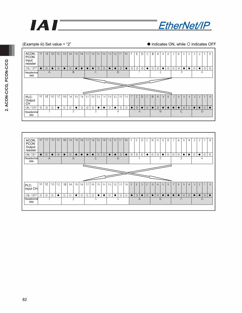
2. A
CO
N-C
/CG
, PC
ON
-C/C
G
82
(Example iii) Set value = “2” indicates ON, while indicates OFF
ACON, PCON Input resister
ACON, PCON Output resister
Hexadecimal data
Hexadecimal data
Hexadecimal data
Hexadecimal data
PLC: Output CH
PLC: Input CH
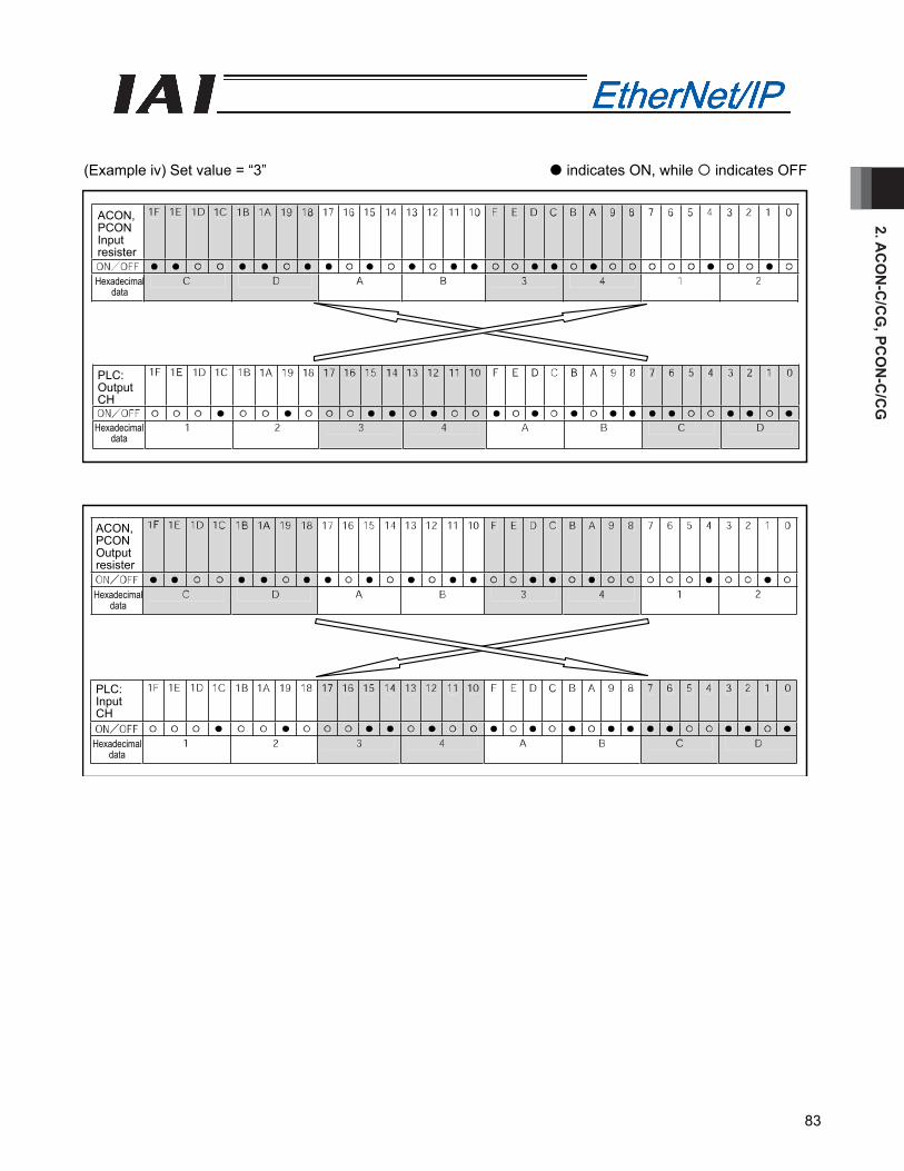
2. AC
ON
-C/C
G, PC
ON
-C/C
G
83
(Example iv) Set value = “3” indicates ON, while indicates OFF
ACON, PCON Input resister
ACON, PCON Output resister
Hexadecimal data
Hexadecimal data
Hexadecimal data
Hexadecimal data
PLC: Output CH
PLC: Input CH

2. A
CO
N-C
/CG
, PC
ON
-C/C
G
84
IP address (No. 140: IPAD)
Specify the IP address in parameter No. 140.
Setting range: 0.0.0.0 to 255.255.255.255 (Factory setting: 192.168.0.1) (Note) When this parameter is set to 0.0.0.0, DHCP is enabled. Manual setting is recommended.
Subnet mask (No. 141: SNMK)
Specify the subnet mask in parameter No. 141.
Settable range: 0.0.0.0 to 255.255.255.255 (Factory setting: 255.255.255.0)
Default gateway (No. 142: DFGW) Specify the default gateway in parameter No. 142.
Settable range: 0.0.0.0 to 255.255.255.255 (Factory setting: 0.0.0.0)
2.10 Troubleshooting
Alarm messages and causes/actions When an alarm occurs, a corresponding simple alarm code is indicated by the completed position number bits (four bits of PM1 to PM8) in remote I/O mode 1, 2 or 3. In position/simple direct mode 1 or 2, this simple alarm code is output to the (n+4, n+5) bytes. In half direct mode 1, 2 or 3 or in the full direct mode, this alarm code is output to the (n+12, n+13) bytes [1] Check the alarm code using the monitor function of the PLC, etc., or connect the RC PC software or
other teaching tool and check the status monitor screen. [2] Search the alarm list in the operation manual for your controller to find the section corresponding to
the identified alarm code. [3] Take an appropriate action according to the explanation of the alarm code.
For the alarm codes listed below, take the corresponding actions:
Code Error name ID (*1)
RES(*2) Cause/action
0F2 Fieldbus module error 05 x Cause: A fieldbus module error has been
detected. Action: Check the applicable parameters.
0F3 Fieldbus module non-detection error 04 x
Cause: The module could not be detected. Action: Reconnect the power. If the problem
persists, please contact IAI. (*1) ID → Simple alarm code (*2) RES → Alarm can/cannot be reset – O: Alarm can be reset / X: Alarm cannot be reset
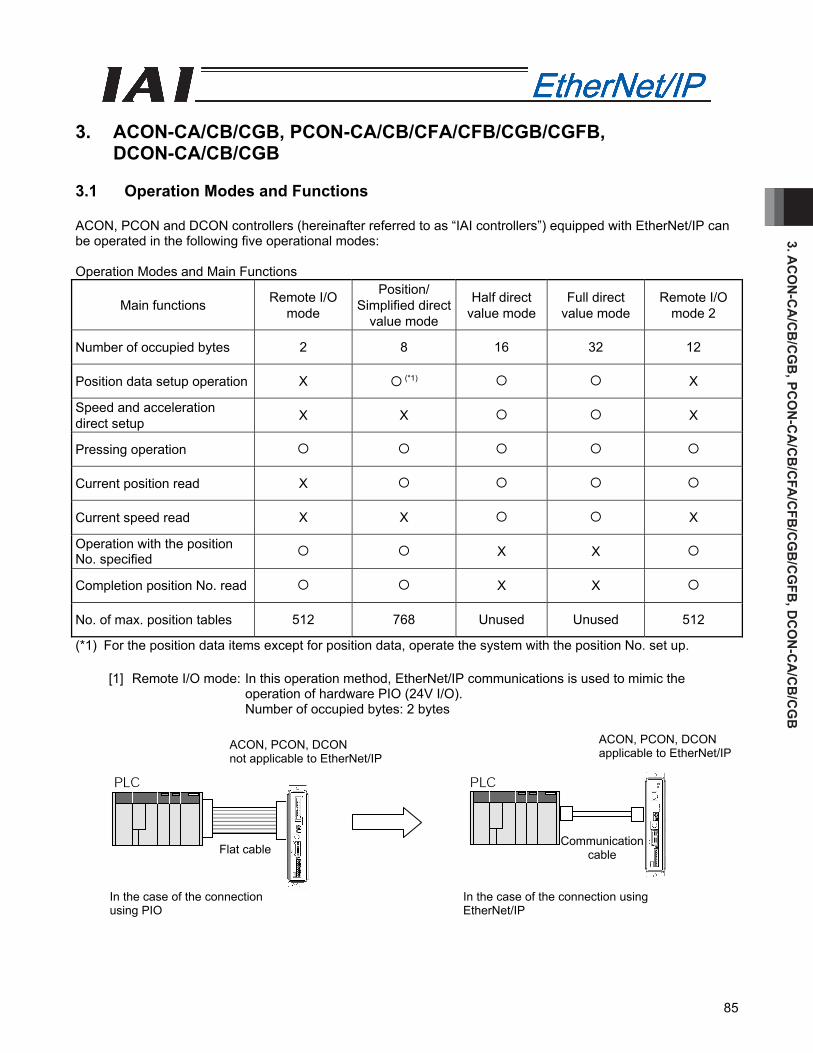
3. AC
ON
-CA
/CB
/CG
B, PC
ON
-CA
/CB
/CFA
/CFB
/CG
B/C
GFB
, DC
ON
-CA
/CB
/CG
B
85
3. ACON-CA/CB/CGB, PCON-CA/CB/CFA/CFB/CGB/CGFB,
DCON-CA/CB/CGB 3.1 Operation Modes and Functions ACON, PCON and DCON controllers (hereinafter referred to as “IAI controllers”) equipped with EtherNet/IP can be operated in the following five operational modes: Operation Modes and Main Functions
Main functions Remote I/O mode
Position/ Simplified direct
value mode
Half direct value mode
Full direct value mode
Remote I/O mode 2
Number of occupied bytes 2 8 16 32 12
Position data setup operation X (*1) X
Speed and acceleration direct setup X X X
Pressing operation
Current position read X
Current speed read X X X
Operation with the position No. specified X X
Completion position No. read X X
No. of max. position tables 512 768 Unused Unused 512
(*1) For the position data items except for position data, operate the system with the position No. set up.
[1] Remote I/O mode: In this operation method, EtherNet/IP communications is used to mimic the operation of hardware PIO (24V I/O). Number of occupied bytes: 2 bytes
Communication cable Flat cable
In the case of the connection using EtherNet/IP
In the case of the connection using PIO
ACON, PCON, DCON applicable to EtherNet/IP
ACON, PCON, DCON not applicable to EtherNet/IP
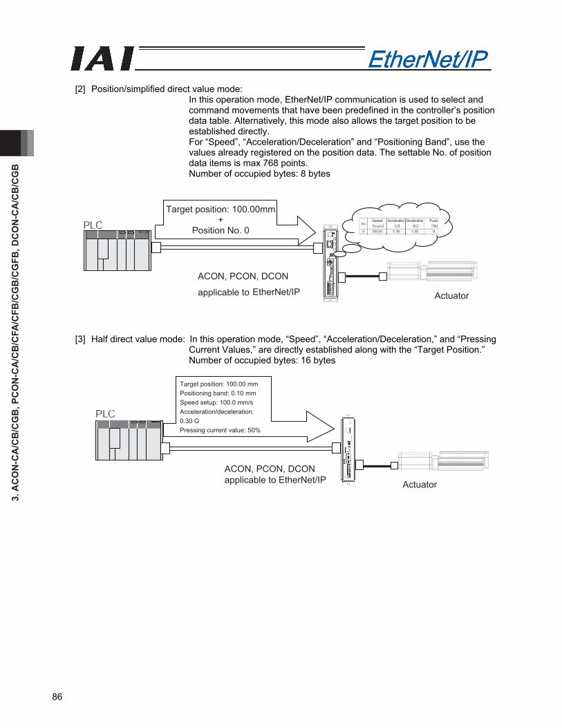
3. A
CO
N-C
A/C
B/C
GB
, PC
ON
-CA
/CB
/CFA
/CFB
/CG
B/C
GFB
, DC
ON
-CA
/CB
/CG
B
86
[2] Position/simplified direct value mode:
In this operation mode, EtherNet/IP communication is used to select and command movements that have been predefined in the controller’s position data table. Alternatively, this mode also allows the target position to be established directly. For “Speed”, “Acceleration/Deceleration” and “Positioning Band”, use the values already registered on the position data. The settable No. of position data items is max 768 points. Number of occupied bytes: 8 bytes
Actuator
ACON, PCON, DCON
applicable to EtherNet/IP
Target position: 100.00mm+
Position No. 0 Speed Acceleration Deceleration Push
[3] Half direct value mode: In this operation mode, “Speed”, “Acceleration/Deceleration,” and “Pressing Current Values,” are directly established along with the “Target Position.” Number of occupied bytes: 16 bytes
Actuator
Target position: 100.00 mm Positioning band: 0.10 mm Speed setup: 100.0 mm/s Acceleration/deceleration: 0.30 G Pressing current value: 50%
ACON, PCON, DCONapplicable to EtherNet/IP
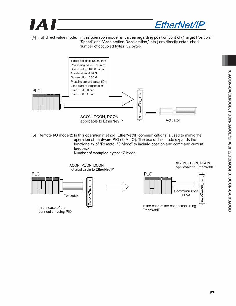
3. AC
ON
-CA
/CB
/CG
B, PC
ON
-CA
/CB
/CFA
/CFB
/CG
B/C
GFB
, DC
ON
-CA
/CB
/CG
B
87
[4] Full direct value mode: In this operation mode, all values regarding position control (“Target Position,”
"Speed” and "Acceleration/Deceleration,” etc.) are directly established. Number of occupied bytes: 32 bytes
[5] Remote I/O mode 2: In this operation method, EtherNet/IP communications is used to mimic the
operation of hardware PIO (24V I/O). The use of this mode expands the functionality of “Remote I/O Mode” to include position and command current feedback. Number of occupied bytes: 12 bytes
Target position: 100.00 mm Positioning band: 0.10 mm Speed setup: 100.0 mm/s Acceleration: 0.30 G Deceleration: 0.30 G Pressing current value: 50% Load current threshold: 0 Zone +: 50.00 mm Zone -: 30.00 mm
Actuator ACON, PCON, DCON applicable to EtherNet/IP
ACON, PCON, DCON applicable to EtherNet/IP ACON, PCON, DCON
not applicable to EtherNet/IP
Communication cable Flat cable
In the case of the connection using EtherNet/IP In the case of the
connection using PIO

3. A
CO
N-C
A/C
B/C
GB
, PC
ON
-CA
/CB
/CFA
/CFB
/CG
B/C
GFB
, DC
ON
-CA
/CB
/CG
B
88
3.2 Model Numbers
The Model numbers of IAI controllers applicable to EtherNet/IP are described as follows.
● ACON-CA/CB- -EP- ● PCON-CA/CB/CGB- -EP- ● PCON-CFA/CFB/CGFB- -EP- ● DCON-CA/CB- -EP-
Front panel color Printed series name● ACON ● PCON ● DCON
● ACON-CA/CB : Dark blue ● PCON-CA/CB/CGB : Dark green ● PCON-CFA/CFB/CGFB : Light green ● DCON-CA/CB : Dark orange
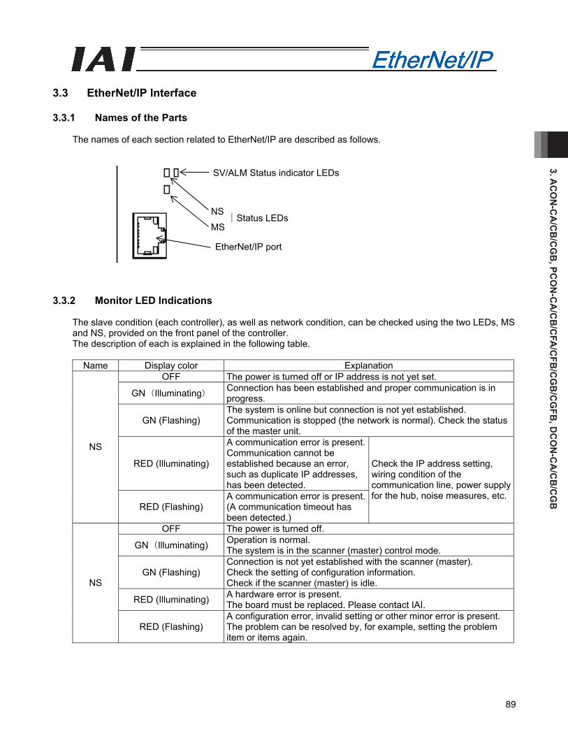
3. AC
ON
-CA
/CB
/CG
B, PC
ON
-CA
/CB
/CFA
/CFB
/CG
B/C
GFB
, DC
ON
-CA
/CB
/CG
B
89
3.3 EtherNet/IP Interface 3.3.1 Names of the Parts
The names of each section related to EtherNet/IP are described as follows. 3.3.2 Monitor LED Indications
The slave condition (each controller), as well as network condition, can be checked using the two LEDs, MS and NS, provided on the front panel of the controller. The description of each is explained in the following table.
Name Display color Explanation
OFF The power is turned off or IP address is not yet set.
GN(Illuminating) Connection has been established and proper communication is in progress.
GN (Flashing) The system is online but connection is not yet established. Communication is stopped (the network is normal). Check the status of the master unit.
RED (Illuminating)
A communication error is present. Communication cannot be established because an error, such as duplicate IP addresses, has been detected.
NS
RED (Flashing) A communication error is present. (A communication timeout has been detected.)
Check the IP address setting, wiring condition of the communication line, power supply for the hub, noise measures, etc.
OFF The power is turned off.
GN(Illuminating) Operation is normal. The system is in the scanner (master) control mode.
GN (Flashing) Connection is not yet established with the scanner (master). Check the setting of configuration information. Check if the scanner (master) is idle.
RED (Illuminating) A hardware error is present. The board must be replaced. Please contact IAI.
NS
RED (Flashing) A configuration error, invalid setting or other minor error is present. The problem can be resolved by, for example, setting the problem item or items again.
SV/ALM Status indicator LEDs
│Status LEDs
EtherNet/IP port
NS
MS

3. A
CO
N-C
A/C
B/C
GB
, PC
ON
-CA
/CB
/CFA
/CFB
/CG
B/C
GFB
, DC
ON
-CA
/CB
/CG
B
90
8
1
3.4 Wiring Example 3.4.1 Connection Diagram
* Ethernet cable: Straight cable of category 5e or above, 100 m max (Aluminum tape and braided double-shielded cable are recommended.)
(Note) Terminal processing is not required.
3.4.2 Connector Pin Layout
Pin number Signal name Signal abbreviation 1 Data transmitted + TD+ 2 Data transmitted - TD- 3 Data received + RD+ 4 Not used 5 Not used 6 Data received - RD- 7 Not used 8 Not used
Connector hood Grounding pin for security FG
RJ45 8-pin modular connector (Controller side)
PLC (EtherNet/IP master unit)
Ethernet cable*
Ethernet cable* Ethernet cable*
Other slaves
ACONPCON
Hub
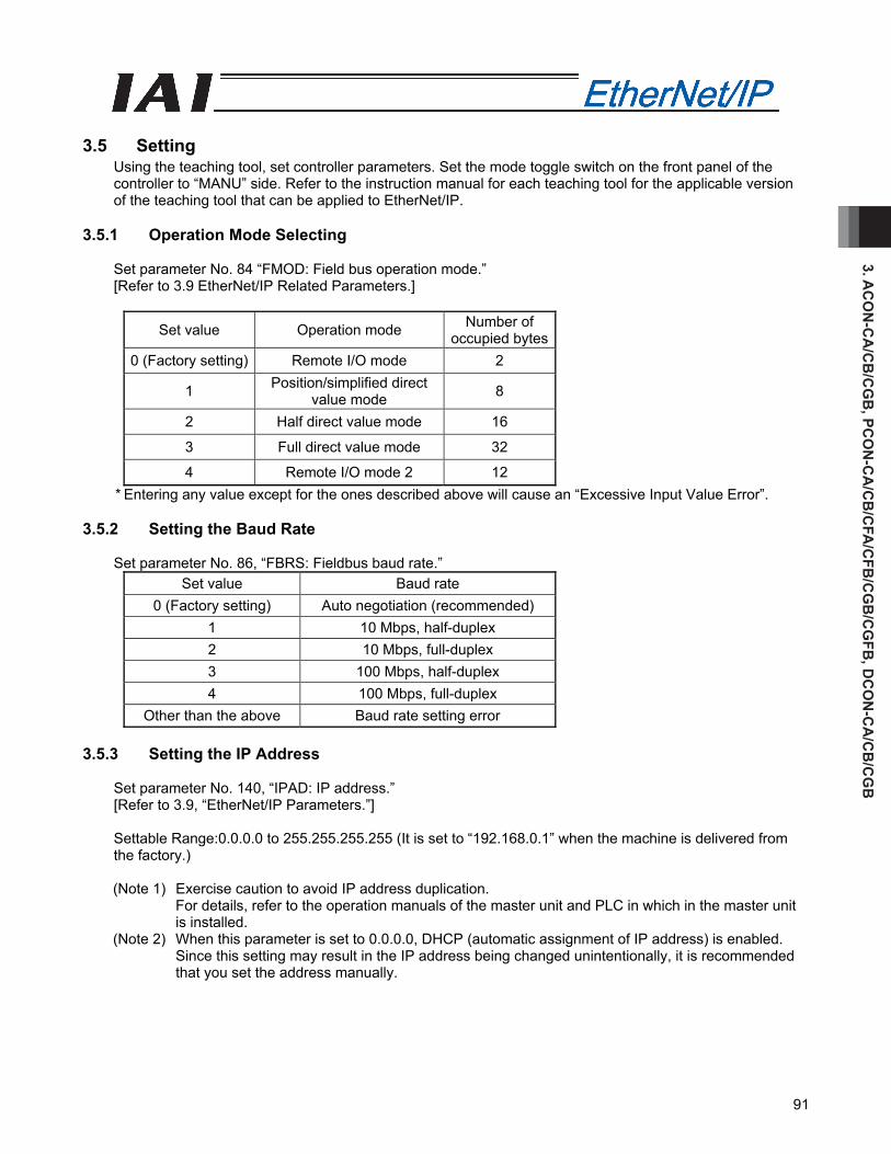
3. AC
ON
-CA
/CB
/CG
B, PC
ON
-CA
/CB
/CFA
/CFB
/CG
B/C
GFB
, DC
ON
-CA
/CB
/CG
B
91
3.5 Setting
Using the teaching tool, set controller parameters. Set the mode toggle switch on the front panel of the controller to “MANU” side. Refer to the instruction manual for each teaching tool for the applicable version of the teaching tool that can be applied to EtherNet/IP.
3.5.1 Operation Mode Selecting
Set parameter No. 84 “FMOD: Field bus operation mode.” [Refer to 3.9 EtherNet/IP Related Parameters.]
Set value Operation mode Number of occupied bytes
0 (Factory setting) Remote I/O mode 2
1 Position/simplified direct value mode 8
2 Half direct value mode 16
3 Full direct value mode 32
4 Remote I/O mode 2 12 * Entering any value except for the ones described above will cause an “Excessive Input Value Error”.
3.5.2 Setting the Baud Rate
Set parameter No. 86, “FBRS: Fieldbus baud rate.” Set value Baud rate
0 (Factory setting) Auto negotiation (recommended) 1 10 Mbps, half-duplex 2 10 Mbps, full-duplex 3 100 Mbps, half-duplex 4 100 Mbps, full-duplex
Other than the above Baud rate setting error 3.5.3 Setting the IP Address
Set parameter No. 140, “IPAD: IP address.” [Refer to 3.9, “EtherNet/IP Parameters.”] Settable Range:0.0.0.0 to 255.255.255.255 (It is set to “192.168.0.1” when the machine is delivered from the factory.) (Note 1) Exercise caution to avoid IP address duplication.
For details, refer to the operation manuals of the master unit and PLC in which in the master unit is installed.
(Note 2) When this parameter is set to 0.0.0.0, DHCP (automatic assignment of IP address) is enabled. Since this setting may result in the IP address being changed unintentionally, it is recommended that you set the address manually.

3. A
CO
N-C
A/C
B/C
GB
, PC
ON
-CA
/CB
/CFA
/CFB
/CG
B/C
GFB
, DC
ON
-CA
/CB
/CG
B
92
3.5.4 Setting the Subnet Mask
Set parameter No. 141, “SNMK: Subnet mask.” Set the same value you have set in the master unit and other slaves (on the same network). [Refer to 3.9, “EtherNet/IP Parameters.”] Settable range: 0.0.0.0 to 255.255.255.255 (The factory setting is 255.255.255.0.)
3.5.5 Setting the Default Gateway
If necessary, set parameter No. 142, “DFGW: Default gateway.” [Refer to 3.9, “EtherNet/IP Parameters.”] Settable range: 0.0.0.0 to 255.255.255.255 (The factory setting is 0.0.0.0.)
(Note) After the parameter setting, turn on the power to the controller again and return the mode toggle switch on the front of the controller to “AUTO” side. When the switch is set to “MANU”, the operation using PLC is not available.

3. AC
ON
-CA
/CB
/CG
B, PC
ON
-CA
/CB
/CFA
/CFB
/CG
B/C
GFB
, DC
ON
-CA
/CB
/CG
B
93
3.6 Communicating with the Master Station 3.6.1 Operation Modes and Corresponding PLC I/O Areas
The addresses allocated for each operation mode are described as follows.
• PLC output → IAI controllers input (* “n” indicates the first output address of each axis.)
DI on the ACON, PCON, DCON side and input data register
Remote I/O mode Position/simplified direct value mode
Half direct value mode
Full direct value mode Remote I/O mode 2PLC output
area (bytes) Number of
occupied bytes: 2 Number of
occupied bytes: 8Number of
occupied bytes: 16Number of
occupied bytes: 32 Number of
occupied bytes: 12n, n+1 Port No.0 to 15 Port No.0 to 15
n+2, n+3 Target position Target position Target position
n+4, n+5 Specified position number
n+6, n+7 Control signal Positioning band Positioning band
n+8, n+9 Speed
n+10, n+11 Acceleration/ deceleration
Speed setup
Occupied area
n+12, n+13 Pressing
current-limiting value
n+14, n+15 Control signal
Zone boundary+
n+16, n+17 n+18, n+19
Zone boundary-
n+20, n+21 Acceleration n+22, n+23 Deceleration
n+24, n+25 Pressing
current-limiting value
n+26, n+27 Load current threshold
n+28, n+29 Control signal 1 n+30, n+31
Control signal 2
(Note) The Occupied area shows the area to be occupied with the operation mode setting.
Therefore, this area cannot be used for any other purpose. Also, exercise caution to avoid node address duplication.

3. A
CO
N-C
A/C
B/C
GB
, PC
ON
-CA
/CB
/CFA
/CFB
/CG
B/C
GFB
, DC
ON
-CA
/CB
/CG
B
94
• IAI controllers output→PLC input side (* “n” indicates the first input address of each axis.)
DO on the ACON, PCON, DCON side and output data register
Remote I/O mode Position/simplified direct value mode
Half direct value mode
Full direct value mode
Remote I/O mode 2
PLC input area
(bytes) Number of occupied bytes: 2
Number of occupied bytes: 8
Number of occupied bytes: 16
Number of occupied bytes: 32
Number of occupied bytes: 12
n, n+1 Port No.0 to 15 Port No.0 to 15n+2, n+3
Current position Current position Current position Occupied area
n+4, n+5 Completed position No.
(simple alarm ID)n+6, n+7 Status Signal
Command current Command current Current position
n+8, n+9 n+10, n+11
Current speed Current speed Command current
n+12, n+13 Alarm code Alarm code n+14, n+15 Status signal n+16, n+17 n+18, n+19
Occupied area
n+20, n+21 n+22, n+23
Total moving count
n+24, n+25 n+26, n+27
Total moving distance
n+28, n+29 Status Signal 1 n+30, n+31
Status signal 2
(Note) The Occupied area shows the area to be occupied with the operation mode setting.
Therefore, this area cannot be used for any other purpose. Also, exercise caution to avoid node address duplication.
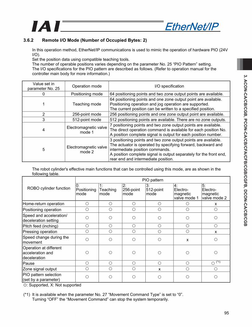
3. AC
ON
-CA
/CB
/CG
B, PC
ON
-CA
/CB
/CFA
/CFB
/CG
B/C
GFB
, DC
ON
-CA
/CB
/CG
B
95
3.6.2 Remote I/O Mode (Number of Occupied Bytes: 2)
In this operation method, EtherNet/IP communications is used to mimic the operation of hardware PIO (24V I/O). Set the position data using compatible teaching tools. The number of operable positions varies depending on the parameter No. 25 “PIO Pattern” setting. The I/O specifications for the PIO pattern are described as follows. (Refer to operation manual for the controller main body for more information.)
Value set in
parameter No. 25 Operation mode I/O specification
0 Positioning mode 64 positioning points and two zone output points are available.
1 Teaching mode 64 positioning points and one zone output point are available. Positioning operation and jog operation are supported. The current position can be written to a specified position.
2 256-point mode 256 positioning points and one zone output point are available. 3 512-point mode 512 positioning points are available. There are no zone outputs.
4 Electromagnetic valve mode 1
7 positioning points and two zone output points are available. The direct operation command is available for each position No.A position complete signal is output for each position number.
5 Electromagnetic valve mode 2
3 positioning points and two zone output points are available. The actuator is operated by specifying forward, backward and intermediate position commands. A position complete signal is output separately for the front end, rear end and intermediate position.
The robot cylinder's effective main functions that can be controlled using this mode, are as shown in the following table.
PIO pattern
ROBO cylinder function 0: Positioning mode
1: Teaching mode
2: 256-point mode
3: 512-point mode
4: Electro- magnetic valve mode 1
5: Electro- magnetic valve mode 2
Home-return operation x Positioning operation Speed and acceleration/ deceleration setting
Pitch feed (inching) Pressing operation x Speed change during the movement x
Operation at different acceleration and deceleration
Pause (*1) Zone signal output x PIO pattern selection (set by a parameter)
: Supported, X: Not supported (*1) It is available when the parameter No. 27 “Movement Command Type” is set to “0”.
Turning “OFF” the “Movement Command” can stop the system temporarily.
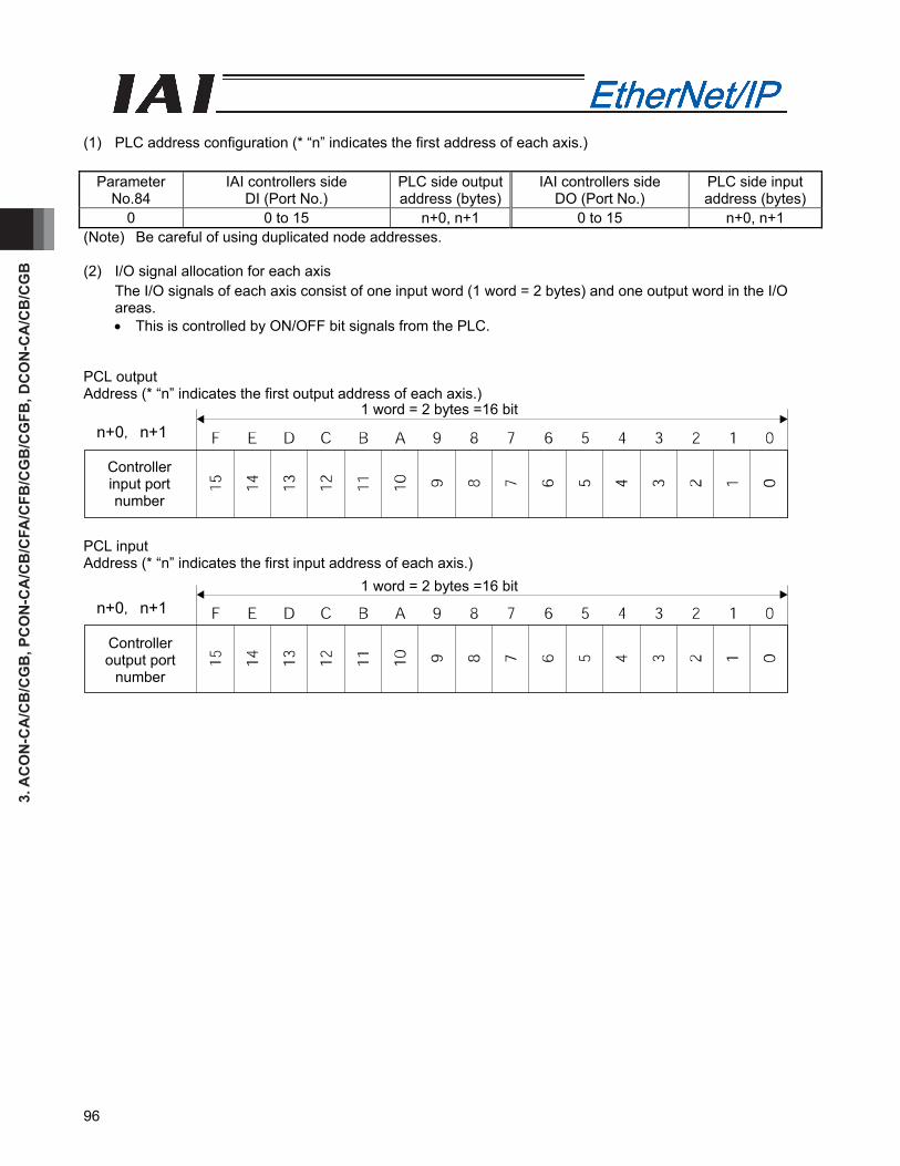
3. A
CO
N-C
A/C
B/C
GB
, PC
ON
-CA
/CB
/CFA
/CFB
/CG
B/C
GFB
, DC
ON
-CA
/CB
/CG
B
96
(1) PLC address configuration (* “n” indicates the first address of each axis.)
Parameter No.84
IAI controllers side DI (Port No.)
PLC side output address (bytes)
IAI controllers side DO (Port No.)
PLC side input address (bytes)
0 0 to 15 n+0, n+1 0 to 15 n+0, n+1 (Note) Be careful of using duplicated node addresses. (2) I/O signal allocation for each axis
The I/O signals of each axis consist of one input word (1 word = 2 bytes) and one output word in the I/O areas. • This is controlled by ON/OFF bit signals from the PLC.
PCL output Address (* “n” indicates the first output address of each axis.) PCL input Address (* “n” indicates the first input address of each axis.)
Controller input port number
1 word = 2 bytes =16 bitn+0, n+1
Controller output port
number
1 word = 2 bytes =16 bitn+0, n+1
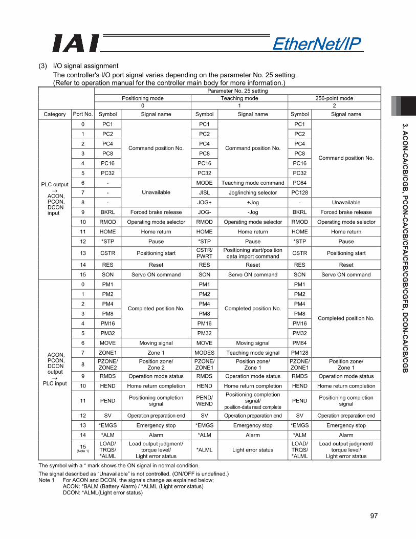
3. AC
ON
-CA
/CB
/CG
B, PC
ON
-CA
/CB
/CFA
/CFB
/CG
B/C
GFB
, DC
ON
-CA
/CB
/CG
B
97
(3) I/O signal assignment
The controller's I/O port signal varies depending on the parameter No. 25 setting. (Refer to operation manual for the controller main body for more information.)
Parameter No. 25 setting Positioning mode Teaching mode 256-point mode
0 1 2 Category Port No. Symbol Signal name Symbol Signal name Symbol Signal name
0 PC1 PC1 PC1
1 PC2 PC2 PC2
2 PC4 PC4 PC4
3 PC8 PC8 PC8
4 PC16 PC16 PC16
5 PC32
Command position No.
PC32
Command position No.
PC32
6 - MODE Teaching mode command PC64
7 - JISL Jog/inching selector PC128
Command position No.
8 -
Unavailable
JOG+ +Jog - Unavailable
9 BKRL Forced brake release JOG- -Jog BKRL Forced brake release
10 RMOD Operating mode selector RMOD Operating mode selector RMOD Operating mode selector
11 HOME Home return HOME Home return HOME Home return
12 *STP Pause *STP Pause *STP Pause
13 CSTR Positioning start CSTR/PWRT
Positioning start/position data import command CSTR Positioning start
14 RES Reset RES Reset RES Reset
PLC output →
ACON, PCON, DCON input
15 SON Servo ON command SON Servo ON command SON Servo ON command
0 PM1 PM1 PM1
1 PM2 PM2 PM2
2 PM4 PM4 PM4
3 PM8 PM8 PM8
4 PM16 PM16 PM16
5 PM32
Completed position No.
PM32
Completed position No.
PM32
6 MOVE Moving signal MOVE Moving signal PM64
7 ZONE1 Zone 1 MODES Teaching mode signal PM128
Completed position No.
8 PZONE/ ZONE2
Position zone/ Zone 2
PZONE/ZONE1
Position zone/ Zone 1
PZONE/ ZONE1
Position zone/ Zone 1
9 RMDS Operation mode status RMDS Operation mode status RMDS Operation mode status
10 HEND Home return completion HEND Home return completion HEND Home return completion
11 PEND Positioning completion signal
PEND/WEND
Positioning completion signal/
position-data read complete PEND Positioning completion
signal
12 SV Operation preparation end SV Operation preparation end SV Operation preparation end
13 *EMGS Emergency stop *EMGS Emergency stop *EMGS Emergency stop
14 *ALM Alarm *ALM Alarm *ALM Alarm
ACON, PCON, DCON output →
PLC input
15 (Note 1)
LOAD/ TRQS/ *ALML
Load output judgment/ torque level/
Light error status *ALML Light error status
LOAD/ TRQS/ *ALML
Load output judgment/ torque level/
Light error status
The symbol with a * mark shows the ON signal in normal condition. The signal described as “Unavailable” is not controlled. (ON/OFF is undefined.) Note 1 For ACON and DCON, the signals change as explained below;
ACON: *BALM (Battery Alarm) / *ALML (Light error status) DCON: *ALML(Light error status)
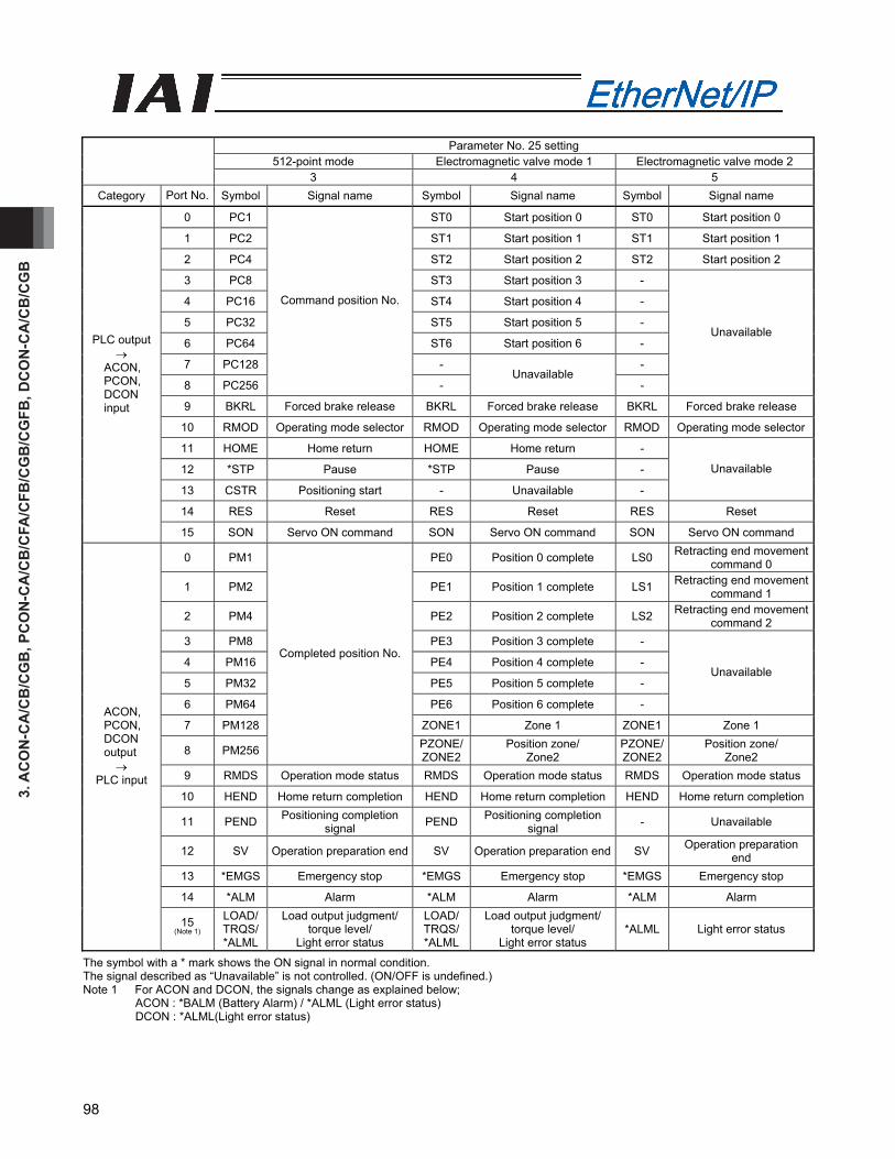
3. A
CO
N-C
A/C
B/C
GB
, PC
ON
-CA
/CB
/CFA
/CFB
/CG
B/C
GFB
, DC
ON
-CA
/CB
/CG
B
98
Parameter No. 25 setting
512-point mode Electromagnetic valve mode 1 Electromagnetic valve mode 2 3 4 5
Category Port No. Symbol Signal name Symbol Signal name Symbol Signal name
0 PC1 ST0 Start position 0 ST0 Start position 0
1 PC2 ST1 Start position 1 ST1 Start position 1
2 PC4 ST2 Start position 2 ST2 Start position 2
3 PC8 ST3 Start position 3 -
4 PC16 ST4 Start position 4 -
5 PC32 ST5 Start position 5 -
6 PC64 ST6 Start position 6 -
7 PC128 - -
8 PC256
Command position No.
- Unavailable
-
Unavailable
9 BKRL Forced brake release BKRL Forced brake release BKRL Forced brake release
10 RMOD Operating mode selector RMOD Operating mode selector RMOD Operating mode selector
11 HOME Home return HOME Home return -
12 *STP Pause *STP Pause -
13 CSTR Positioning start - Unavailable -
Unavailable
14 RES Reset RES Reset RES Reset
PLC output →
ACON, PCON, DCON input
15 SON Servo ON command SON Servo ON command SON Servo ON command
0 PM1 PE0 Position 0 complete LS0 Retracting end movement command 0
1 PM2 PE1 Position 1 complete LS1 Retracting end movement command 1
2 PM4 PE2 Position 2 complete LS2 Retracting end movement command 2
3 PM8 PE3 Position 3 complete -
4 PM16 PE4 Position 4 complete -
5 PM32 PE5 Position 5 complete -
6 PM64 PE6 Position 6 complete -
Unavailable
7 PM128 ZONE1 Zone 1 ZONE1 Zone 1
8 PM256
Completed position No.
PZONE/ZONE2
Position zone/ Zone2
PZONE/ ZONE2
Position zone/ Zone2
9 RMDS Operation mode status RMDS Operation mode status RMDS Operation mode status
10 HEND Home return completion HEND Home return completion HEND Home return completion
11 PEND Positioning completion signal PEND Positioning completion
signal - Unavailable
12 SV Operation preparation end SV Operation preparation end SV Operation preparation end
13 *EMGS Emergency stop *EMGS Emergency stop *EMGS Emergency stop
14 *ALM Alarm *ALM Alarm *ALM Alarm
ACON, PCON, DCON output →
PLC input
15 (Note 1)
LOAD/ TRQS/ *ALML
Load output judgment/ torque level/
Light error status
LOAD/TRQS/*ALML
Load output judgment/ torque level/
Light error status *ALML Light error status
The symbol with a * mark shows the ON signal in normal condition. The signal described as “Unavailable” is not controlled. (ON/OFF is undefined.) Note 1 For ACON and DCON, the signals change as explained below;
ACON : *BALM (Battery Alarm) / *ALML (Light error status) DCON : *ALML(Light error status)
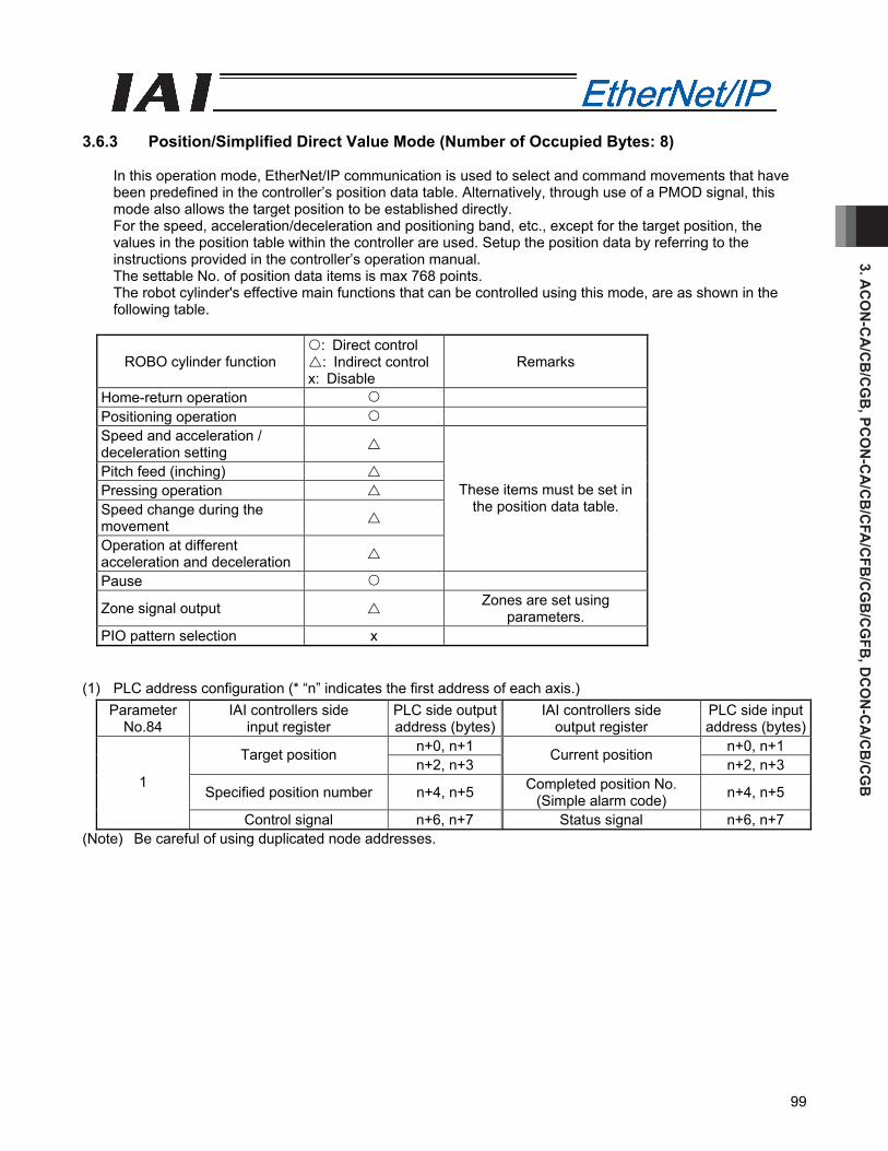
3. AC
ON
-CA
/CB
/CG
B, PC
ON
-CA
/CB
/CFA
/CFB
/CG
B/C
GFB
, DC
ON
-CA
/CB
/CG
B
99
3.6.3 Position/Simplified Direct Value Mode (Number of Occupied Bytes: 8)
In this operation mode, EtherNet/IP communication is used to select and command movements that have been predefined in the controller’s position data table. Alternatively, through use of a PMOD signal, this mode also allows the target position to be established directly. For the speed, acceleration/deceleration and positioning band, etc., except for the target position, the values in the position table within the controller are used. Setup the position data by referring to the instructions provided in the controller’s operation manual. The settable No. of position data items is max 768 points. The robot cylinder's effective main functions that can be controlled using this mode, are as shown in the following table.
ROBO cylinder function : Direct control : Indirect control
x: Disable Remarks
Home-return operation Positioning operation Speed and acceleration / deceleration setting
Pitch feed (inching) Pressing operation Speed change during the movement
Operation at different acceleration and deceleration
These items must be set in the position data table.
Pause
Zone signal output Zones are set using parameters.
PIO pattern selection x
(1) PLC address configuration (* “n” indicates the first address of each axis.)
Parameter No.84
IAI controllers side input register
PLC side output address (bytes)
IAI controllers side output register
PLC side input address (bytes)
n+0, n+1 n+0, n+1 Target position n+2, n+3
Current position n+2, n+3
Specified position number n+4, n+5 Completed position No. (Simple alarm code) n+4, n+5
1
Control signal n+6, n+7 Status signal n+6, n+7 (Note) Be careful of using duplicated node addresses.

3. A
CO
N-C
A/C
B/C
GB
, PC
ON
-CA
/CB
/CFA
/CFB
/CG
B/C
GFB
, DC
ON
-CA
/CB
/CG
B
100
(2) I/O signal allocation for each axis
The I/O signals of each axis consist of four input words (4 words = 8 bytes) and four output words in the I/O areas.
The control signals and status signals are ON/OFF signals in units of bit. The target position and current position are expressed using 2 words (32 bits) binary data. The figures
from –999999 to +999999 (Unit: 0.01mm) can be set in PLC. However, set the position data within the soft stroke range (0 to effective stroke length) for the actuator concerned.
The specified position No. and completed position No. are expressed using 1-word (16 bits) binary data. The figures from 0 to 767 can be set in PLC. However, set the position No. for which the operation conditions have been set in advance using the PC software or teaching tools.
PLC output Address (* "n" indicates the first output address of each axis.)
When the target position is shown using the negative figure, it is expressed using the complement of 2.
1 word = 2 bytes =16 bits
Target position (lower word)
Target position (upper word)
n+2, n+3
n+0, n+1
Specified position number
Control signal
n+4, n+5
n+6, n+7

3. AC
ON
-CA
/CB
/CG
B, PC
ON
-CA
/CB
/CFA
/CFB
/CG
B/C
GFB
, DC
ON
-CA
/CB
/CG
B
101
PLC input Address (* “n” indicates the first input address of each axis.)
When the current position is shown using the negative figure, it is expressed using the complement of 2. Note 1 For ACON, it can be changed to BALM by the setting in Parameter No. 151.
1 word = 2 bytes =16 bits
Current position
(lower word)
Current position
(upper word)
n+0, n+1
n+2, n+3
Completed position No.
Status signal
n+4, n+5
n+6, n+7
ALM
L (N
ote
1)
ZON
E2
ZON
E1
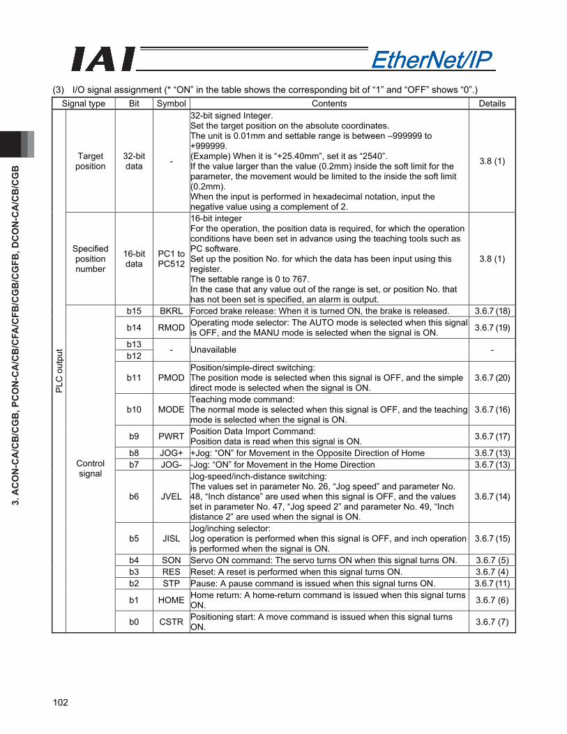
3. A
CO
N-C
A/C
B/C
GB
, PC
ON
-CA
/CB
/CFA
/CFB
/CG
B/C
GFB
, DC
ON
-CA
/CB
/CG
B
102
(3) I/O signal assignment (* “ON” in the table shows the corresponding bit of “1” and “OFF” shows “0”.)
Signal type Bit Symbol Contents Details
Target position
32-bit data -
32-bit signed Integer. Set the target position on the absolute coordinates. The unit is 0.01mm and settable range is between –999999 to +999999. (Example) When it is “+25.40mm”, set it as “2540”. If the value larger than the value (0.2mm) inside the soft limit for the parameter, the movement would be limited to the inside the soft limit (0.2mm). When the input is performed in hexadecimal notation, input the negative value using a complement of 2.
3.8 (1)
Specified position number
16-bit data
PC1 to PC512
16-bit integer For the operation, the position data is required, for which the operation conditions have been set in advance using the teaching tools such as PC software. Set up the position No. for which the data has been input using this register. The settable range is 0 to 767. In the case that any value out of the range is set, or position No. that has not been set is specified, an alarm is output.
3.8 (1)
b15 BKRL Forced brake release: When it is turned ON, the brake is released. 3.6.7 (18)
b14 RMOD Operating mode selector: The AUTO mode is selected when this signal is OFF, and the MANU mode is selected when the signal is ON. 3.6.7 (19)
b13 b12
- Unavailable -
b11 PMOD Position/simple-direct switching: The position mode is selected when this signal is OFF, and the simple direct mode is selected when the signal is ON.
3.6.7 (20)
b10 MODE Teaching mode command: The normal mode is selected when this signal is OFF, and the teaching mode is selected when the signal is ON.
3.6.7 (16)
b9 PWRT Position Data Import Command: Position data is read when this signal is ON. 3.6.7 (17)
b8 JOG+ +Jog: “ON” for Movement in the Opposite Direction of Home 3.6.7 (13)b7 JOG- -Jog: “ON” for Movement in the Home Direction 3.6.7 (13)
b6 JVEL
Jog-speed/inch-distance switching: The values set in parameter No. 26, “Jog speed” and parameter No. 48, “Inch distance” are used when this signal is OFF, and the values set in parameter No. 47, “Jog speed 2” and parameter No. 49, “Inch distance 2” are used when the signal is ON.
3.6.7 (14)
b5 JISL Jog/inching selector: Jog operation is performed when this signal is OFF, and inch operation is performed when the signal is ON.
3.6.7 (15)
b4 SON Servo ON command: The servo turns ON when this signal turns ON. 3.6.7 (5)b3 RES Reset: A reset is performed when this signal turns ON. 3.6.7 (4)b2 STP Pause: A pause command is issued when this signal turns ON. 3.6.7 (11)
b1 HOME Home return: A home-return command is issued when this signal turns ON. 3.6.7 (6)
PLC
out
put
Control signal
b0 CSTR Positioning start: A move command is issued when this signal turns ON. 3.6.7 (7)

3. AC
ON
-CA
/CB
/CG
B, PC
ON
-CA
/CB
/CFA
/CFB
/CG
B/C
GFB
, DC
ON
-CA
/CB
/CG
B
103
(* “ON” in the table shows the corresponding bit of “1” and “OFF” shows “0”.)
Signal type Bit Symbol Contents Details
Current position 32-bit -
Current position: 32-bit signed Integer. The setting unit is 0.01mm. (Example) Reading:000003FFH=1023 (decimal)=10.23mm * When the value is read in hexadecimal notation, the negative figure is expressed as a complement of 2.
3.8 (1)
Completed position No.
(Simple alarm code)
16-bit PM1 to PM512
16-bit integer It is moved to the target position and the positioning completed position No. within the positioning band is output. In the case that the position movement has not been performed at all, or during the movement, “0” is output. When an alarm is issued (in the case that the status signal ALM is “ON”), the simplified alarm code (Refer to the operation manual for the controller main body) is output.
3.8 (1)
b15 EMGS Emergency stop: An emergency stop is actuated when this signal turns ON. 3.6.7 (2)
b14 PWR Controller ready : This signal turns ON when the controller becomes ready. 3.6.7 (1)
b13 ZONE2 Zone 2:“ON” for the current position within the zone set range 3.6.7 (12)
b12 ZONE1 Zone 1:“ON” for the current position within the zone set range 3.6.7 (12)
b11 PZONE Position zone: This signal turns ON when the current position is inside the specified position zone.
3.6.7 (12)
b10 MODES Teaching mode signal: This signal is ON while the teaching mode is selected. 3.6.7 (16)
b9 WEND Position-data read complete : This signal turns ON when reading is complete. 3.6.7 (17)
b8 RMDS Operation mode status: This signal is OFF when the current mode is AUTO, or ON when the current mode is MANU.
3.6.7 (19)
ALML
Light error status: Turns ON when light alarm (threshold exceeded for number of movement, etc.) that the operation can be continued with is issued. Note: ALM LED would not turn ON with a light error.
3.6.7 (31)
b7
BALM ☆When Parameter No. 151 is set to 1 in ACON, absolute battery voltage drop warning turns ON when the voltage is dropped. 3.6.7 (32)
b6 - Unavailable -
b5 PSEL Pressing and a Miss: This signal turns ON when the actuator missed the work part in pressing operation. 3.6.7 (23)
b4 SV Operation preparation end: This signal turns ON when the servo turns ON. 3.6.7 (5)
b3 ALM Alarm: This signal turns ON when an alarm occurs. 3.6.7 (3)
b2 MOVE Moving signal: This signal remains ON while the actuator is moving. 3.6.7 (9)
b1 HEND Home return completion: This signal turns ON when home return is completed. 3.6.7 (6)
PLC
inpu
t
Status code
b0 PEND Positioning completion signal: This signal turns ON when positioning is completed. 3.6.7 (10)

3. A
CO
N-C
A/C
B/C
GB
, PC
ON
-CA
/CB
/CFA
/CFB
/CG
B/C
GFB
, DC
ON
-CA
/CB
/CG
B
104
3.6.4 Half Direct Value Mode (Number of Occupied Bytes: 16)
This is the operation mode with the target position, positioning band, speed, acceleration/deceleration and pressing current value set up in the PLC. Set each value in the I/O areas. When the zone function is used, set it using the parameter Nos. 1, 2, 23 and 24. The robot cylinder's effective main functions that can be controlled using this mode, are as shown in the following table.
ROBO cylinder function : Direct control : Indirect control
x: Disable Remark
Home-return operation Positioning operation Speed and acceleration / deceleration setting
Pitch feed (inching) Pressing operation Speed change during the movement
Operation at different acceleration and deceleration x
Pause Zone signal output Parameters must be set. PIO pattern selection x
(1) PLC address configuration. (* "n" indicates the first address of each axis.)
Parameter No.84
IAI controllers side input register
PLC side output address (bytes)
IAI controllers side output register
PLC side input address (bytes)
n, n+1 n, n+1 Target position n+2, n+3
Current position n+2, n+3
n+4, n+5 n+4, n+5 Positioning band n+6, n+7
Command current n+6, n+7
Speed n+8, n+9 n+8, n+9 Acceleration/ deceleration n+10, n+11
Current speed n+10, n+11
Pressing current-limiting value n+12, n+13 Alarm code n+12, n+13
2
Control signal n+14, n+15 Status signal n+14, n+15 (Note) Be careful of using duplicated node addresses.

3. AC
ON
-CA
/CB
/CG
B, PC
ON
-CA
/CB
/CFA
/CFB
/CG
B/C
GFB
, DC
ON
-CA
/CB
/CG
B
105
(2) I/O signal allocation for each axis
The I/O signals of each axis consist of one input word (8 words = 16 bytes) and one output word in the I/O areas.
The control signals and status signals are ON/OFF signals in units of bit. The target position and current position are expressed using 2-word (32 bits) binary data. The figures
from –999999 to +999999 (Unit: 0.01mm) can be set in PLC. However, set the position data within the soft stroke range (0 to effective stroke length) for the actuator concerned.
Set the positioning band. The positioning band is expressed using 2-word (32 bits) binary data. The figures from 1 to +999999 (Unit: 0.01mm) can be set in PLC.
The specified speed is expressed using 1-word (16 bits) binary data. The figures from 0 to +65535 (Unit: 1.0mm/sec or 0.1mm/sec) can be set in PLC. Set the value that does not exceed the max. speed value for the actuator in question. The unit can be established in Parameter No. 159 FB Half Direct Mode Speed Unit.
Parameter No.159 Setting Value Indicated Speed Unit 0 1.0mm/sec 1 0.1mm/sec
The Acceleration/deceleration is expressed using 1-word (16 bits) binary data. The figures from 1 to 300 (Unit: 0.01G) can be set in PLC. However, set the value that does not exceed the max. acceleration/deceleration value for the actuator in question.
The pressing current-limiting value is expressed using 1-word (16 bits) binary data. The figures from 0 (0%) to 255 (100%) can be set in PLC. However, set the value within the settable range for the pressing current-limiting value (Refer to the Catalog or operation manual for the actuator) for the actuator concerned.
Set value Pressing current-limiting value
The command current is expressed using 2-word (32 bits) binary data (Unit: 1mA). The current speed is expressed using 2-word (32 bits) binary data (Unit: 0.01mm/sec). The alarm code is expressed using 1-word (16 bits) binary data.
127
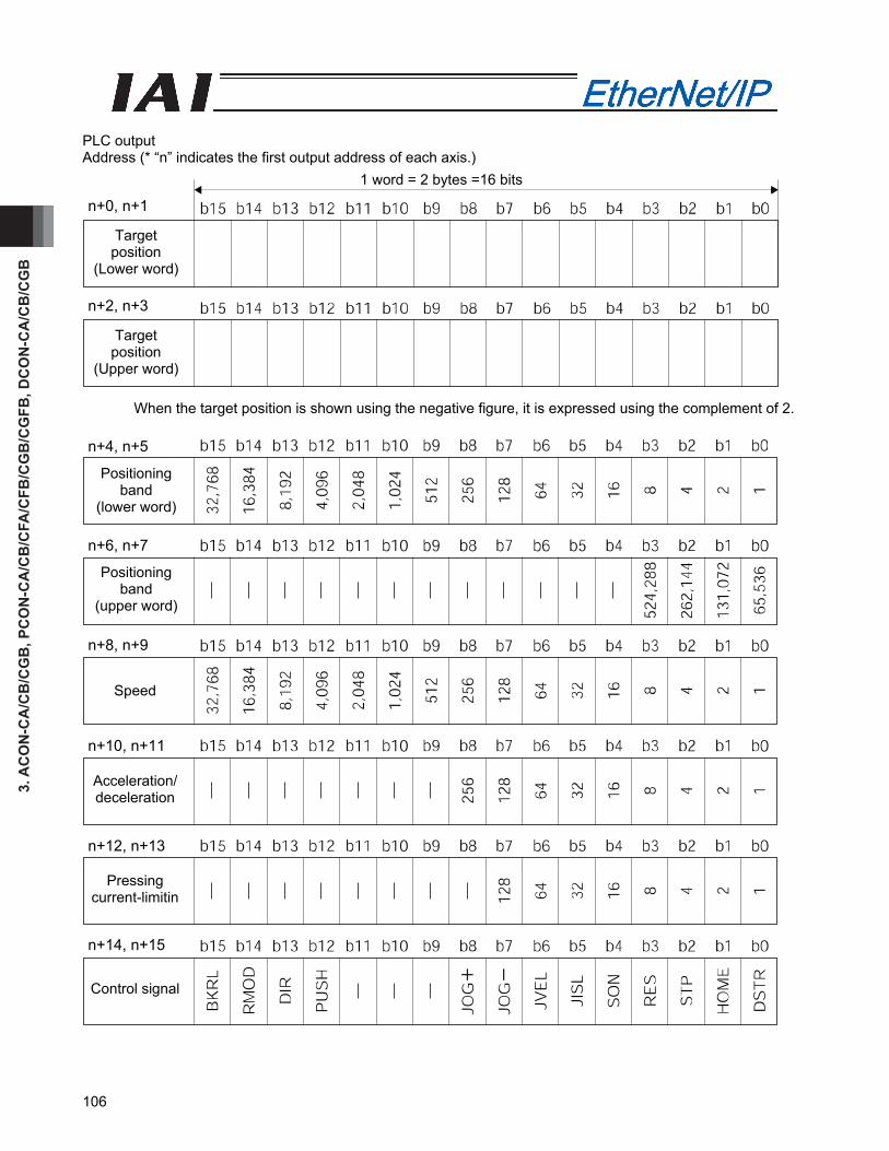
3. A
CO
N-C
A/C
B/C
GB
, PC
ON
-CA
/CB
/CFA
/CFB
/CG
B/C
GFB
, DC
ON
-CA
/CB
/CG
B
106
PLC output Address (* “n” indicates the first output address of each axis.)
When the target position is shown using the negative figure, it is expressed using the complement of 2.
1 word = 2 bytes =16 bits
Target position
(Lower word)
Target position
(Upper word)
n+2, n+3
n+0, n+1
Positioning band
(lower word)
Speed
Acceleration/ deceleration
Pressing current-limitin
Control signal
Positioning band
(upper word)
n+12, n+13
n+10, n+11
n+8, n+9
n+6, n+7
n+4, n+5
n+14, n+15
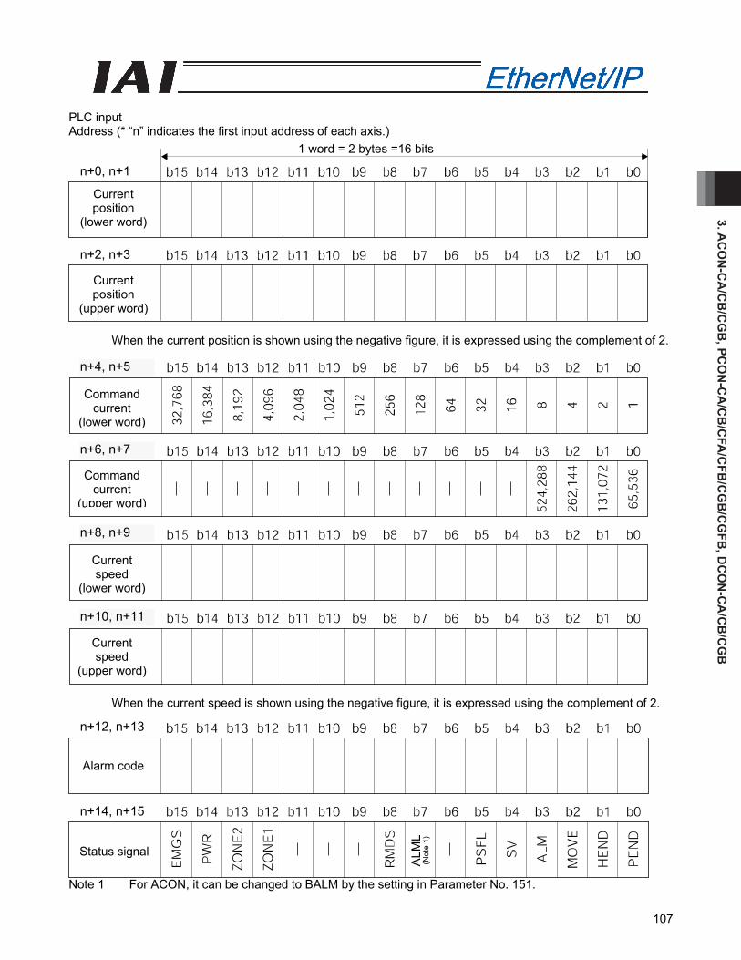
3. AC
ON
-CA
/CB
/CG
B, PC
ON
-CA
/CB
/CFA
/CFB
/CG
B/C
GFB
, DC
ON
-CA
/CB
/CG
B
107
PLC input Address (* “n” indicates the first input address of each axis.)
When the current position is shown using the negative figure, it is expressed using the complement of 2. When the current speed is shown using the negative figure, it is expressed using the complement of 2.
Note 1 For ACON, it can be changed to BALM by the setting in Parameter No. 151.
Current position
(lower word)
Current position
(upper word)
1 word = 2 bytes =16 bits
n+2, n+3
n+0, n+1
Alarm code
Status signal
Command current
(lower word)
Command current
(upper word)
Current speed
(upper word)
Current speed
(lower word)
n+12, n+13
n+10, n+11
n+8, n+9
n+6, n+7
n+4, n+5
n+14, n+15
ALM
L (N
ote
1)
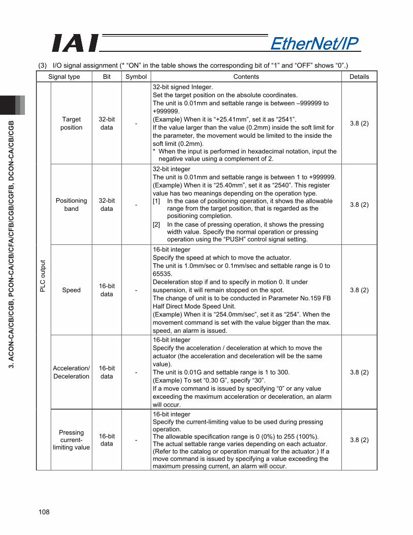
3. A
CO
N-C
A/C
B/C
GB
, PC
ON
-CA
/CB
/CFA
/CFB
/CG
B/C
GFB
, DC
ON
-CA
/CB
/CG
B
108
(3) I/O signal assignment (* “ON” in the table shows the corresponding bit of “1” and “OFF” shows “0”.)
Signal type Bit Symbol Contents Details
Target position
32-bit data -
32-bit signed Integer. Set the target position on the absolute coordinates. The unit is 0.01mm and settable range is between –999999 to +999999. (Example) When it is “+25.41mm”, set it as “2541”. If the value larger than the value (0.2mm) inside the soft limit for the parameter, the movement would be limited to the inside the soft limit (0.2mm). * When the input is performed in hexadecimal notation, input the
negative value using a complement of 2.
3.8 (2)
Positioning band
32-bit data -
32-bit integer The unit is 0.01mm and settable range is between 1 to +999999.(Example) When it is “25.40mm”, set it as “2540”. This register value has two meanings depending on the operation type. [1] In the case of positioning operation, it shows the allowable
range from the target position, that is regarded as the positioning completion.
[2] In the case of pressing operation, it shows the pressing width value. Specify the normal operation or pressing operation using the “PUSH” control signal setting.
3.8 (2)
Speed 16-bit data -
16-bit integer Specify the speed at which to move the actuator. The unit is 1.0mm/sec or 0.1mm/sec and settable range is 0 to 65535. Deceleration stop if and to specify in motion 0. It under suspension, it will remain stopped on the spot. The change of unit is to be conducted in Parameter No.159 FB Half Direct Mode Speed Unit. (Example) When it is “254.0mm/sec”, set it as “254”. When the movement command is set with the value bigger than the max. speed, an alarm is issued.
3.8 (2)
Acceleration/ Deceleration
16-bit data -
16-bit integer Specify the acceleration / deceleration at which to move the actuator (the acceleration and deceleration will be the same value). The unit is 0.01G and settable range is 1 to 300. (Example) To set “0.30 G”, specify “30”. If a move command is issued by specifying “0” or any value exceeding the maximum acceleration or deceleration, an alarm will occur.
3.8 (2)
PLC
out
put
Pressing current-
limiting value
16-bit data -
16-bit integer Specify the current-limiting value to be used during pressing operation. The allowable specification range is 0 (0%) to 255 (100%). The actual settable range varies depending on each actuator. (Refer to the catalog or operation manual for the actuator.) If a move command is issued by specifying a value exceeding the maximum pressing current, an alarm will occur.
3.8 (2)
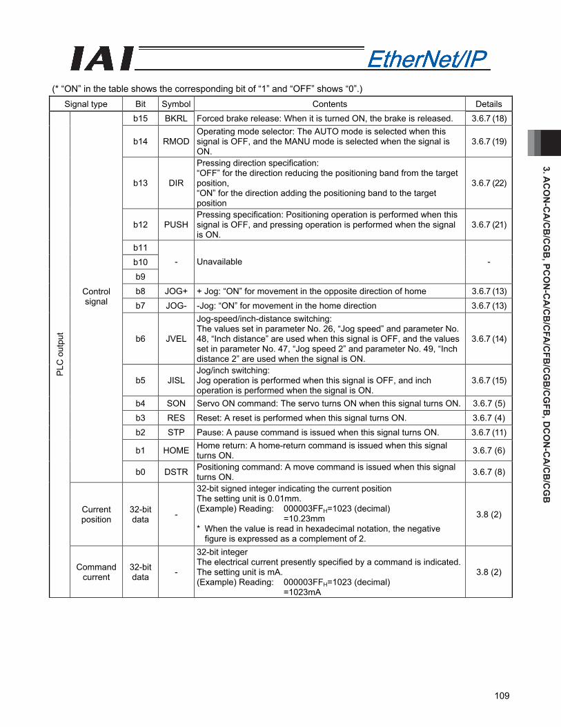
3. AC
ON
-CA
/CB
/CG
B, PC
ON
-CA
/CB
/CFA
/CFB
/CG
B/C
GFB
, DC
ON
-CA
/CB
/CG
B
109
(* “ON” in the table shows the corresponding bit of “1” and “OFF” shows “0”.)
Signal type Bit Symbol Contents Details b15 BKRL Forced brake release: When it is turned ON, the brake is released. 3.6.7 (18)
b14 RMOD Operating mode selector: The AUTO mode is selected when this signal is OFF, and the MANU mode is selected when the signal is ON.
3.6.7 (19)
b13 DIR
Pressing direction specification: “OFF” for the direction reducing the positioning band from the target position, “ON” for the direction adding the positioning band to the target position
3.6.7 (22)
b12 PUSH Pressing specification: Positioning operation is performed when this signal is OFF, and pressing operation is performed when the signal is ON.
3.6.7 (21)
b11
b10
b9
- Unavailable -
b8 JOG+ + Jog: “ON” for movement in the opposite direction of home 3.6.7 (13)
b7 JOG- -Jog: “ON” for movement in the home direction 3.6.7 (13)
b6 JVEL
Jog-speed/inch-distance switching: The values set in parameter No. 26, “Jog speed” and parameter No. 48, “Inch distance” are used when this signal is OFF, and the values set in parameter No. 47, “Jog speed 2” and parameter No. 49, “Inch distance 2” are used when the signal is ON.
3.6.7 (14)
b5 JISL Jog/inch switching: Jog operation is performed when this signal is OFF, and inch operation is performed when the signal is ON.
3.6.7 (15)
b4 SON Servo ON command: The servo turns ON when this signal turns ON. 3.6.7 (5)
b3 RES Reset: A reset is performed when this signal turns ON. 3.6.7 (4)
b2 STP Pause: A pause command is issued when this signal turns ON. 3.6.7 (11)
b1 HOME Home return: A home-return command is issued when this signal turns ON. 3.6.7 (6)
Control signal
b0 DSTR Positioning command: A move command is issued when this signal turns ON. 3.6.7 (8)
Current position
32-bit data -
32-bit signed integer indicating the current position The setting unit is 0.01mm. (Example) Reading: 000003FFH=1023 (decimal)
=10.23mm * When the value is read in hexadecimal notation, the negative
figure is expressed as a complement of 2.
3.8 (2)
PLC
out
put
Command current
32-bit data -
32-bit integer The electrical current presently specified by a command is indicated.The setting unit is mA. (Example) Reading: 000003FFH=1023 (decimal)
=1023mA
3.8 (2)

3. A
CO
N-C
A/C
B/C
GB
, PC
ON
-CA
/CB
/CFA
/CFB
/CG
B/C
GFB
, DC
ON
-CA
/CB
/CG
B
110
(* “ON” in the table shows the corresponding bit of “1” and “OFF” shows “0”.)
Signal type Bit Symbol Contents Details
Current speed
32-bit data -
32-bit signed integer indicating the current position The current speed is indicated. Positive value: The actuator is moving in the direction opposite home. Negative value: The actuator is moving in the direction of home. The setting unit is 0.01mm/sec. (Example) Reading: 000003FFH=1023 (decimal)
=10.23mm/sec * When the value is read in hexadecimal notation, the negative
figure is expressed as a complement of 2.
3.8 (2)
Alarm code 16-bit data -
16-bit integer When an alarm is issued, the alarm code is output. When any alarm is not issued, it is “0H”. Refer to the operation manual for the controller main body for the details of the alarms.
3.8 (2)
b15 EMGS Emergency stop: An emergency stop is actuated when this signal turns ON. 3.6.7 (2)
b14 PWR Controller ready: This signal turns ON when the controller becomes ready. 3.6.7 (1)
b13 ZONE2 Zone 2: “ON” for the current position within the zone set range 3.6.7 (12)
b12 ZONE1 Zone 1: “ON” for the current position within the zone set range 3.6.7 (12)
b11
b10
b9
- Unavailable -
b8 RMDS Operation mode status: This signal is OFF when the current mode is AUTO, or ON when the current mode is MANU.
3.6.7 (19)
ALML
Light error status: Turns ON when light alarm (threshold exceeded for number of movement, etc.) that the operation can be continued with is issued. Note: ALM LED would not turn ON with a light error.
3.6.7 (31) b7
BALM ☆When Parameter No. 151 is set to 1 in ACON, absolute battery voltage drop warning turns ON when the voltage is dropped.
3.6.7 (32)
b6 - Unavailable -
b5 PSEL Pressing and a Miss: This signal turns ON when the actuator missed the work part in pressing operation.
3.6.7 (23)
b4 SV Operation preparation end: This signal turns ON when the servo turns ON. 3.6.7 (5)
b3 ALM Alarm: This signal turns ON when an alarm occurs. 3.6.7 (3)
b2 MOVE Moving signal: This signal remains ON while the actuator is moving. 3.6.7 (9)
b1 HEND Home return completion: This signal turns ON when home return is completed. 3.6.7 (6)
PLC
inpu
t
Status signal
b0 PEND Positioning completion signal: This signal turns ON when positioning is completed.
3.6.7 (10)
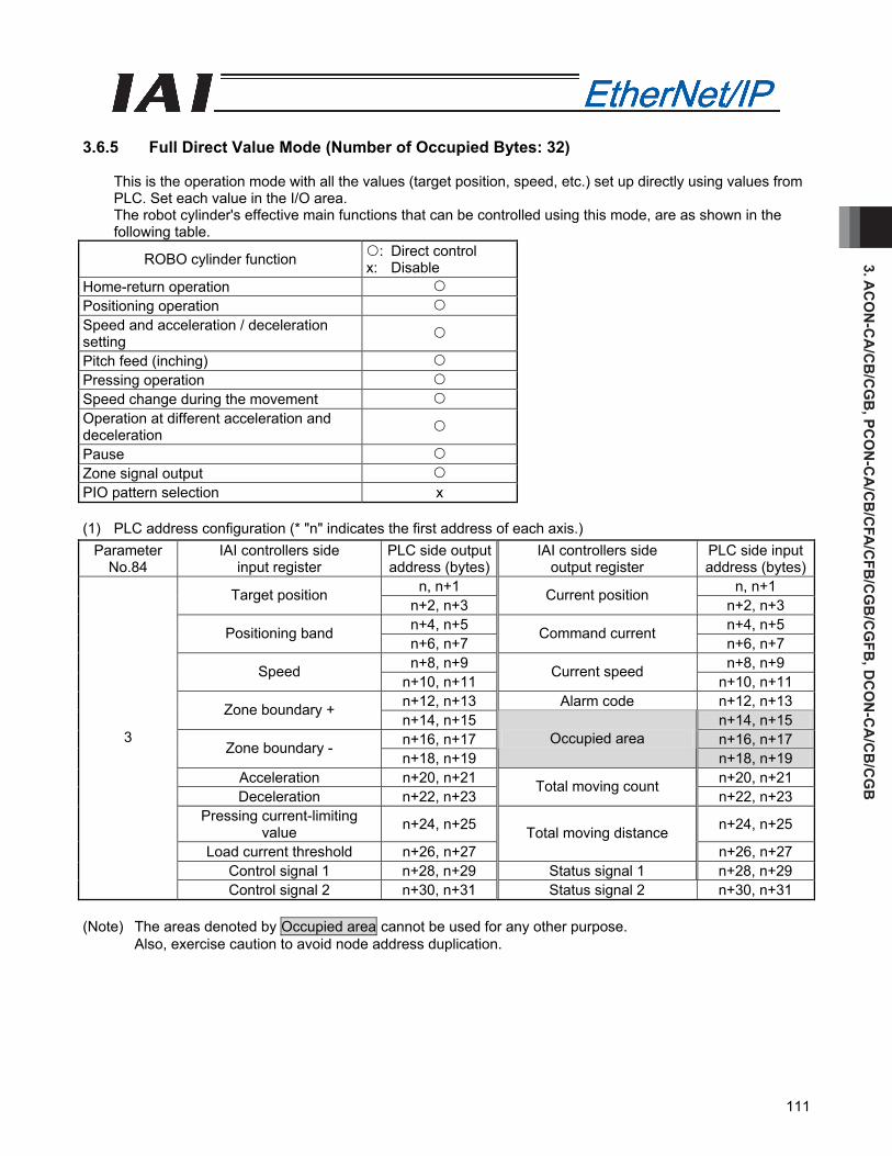
3. AC
ON
-CA
/CB
/CG
B, PC
ON
-CA
/CB
/CFA
/CFB
/CG
B/C
GFB
, DC
ON
-CA
/CB
/CG
B
111
3.6.5 Full Direct Value Mode (Number of Occupied Bytes: 32)
This is the operation mode with all the values (target position, speed, etc.) set up directly using values from PLC. Set each value in the I/O area. The robot cylinder's effective main functions that can be controlled using this mode, are as shown in the following table.
ROBO cylinder function : Direct control x: Disable
Home-return operation Positioning operation Speed and acceleration / deceleration setting
Pitch feed (inching) Pressing operation Speed change during the movement Operation at different acceleration and deceleration
Pause Zone signal output PIO pattern selection x (1) PLC address configuration (* "n" indicates the first address of each axis.)
Parameter No.84
IAI controllers side input register
PLC side output address (bytes)
IAI controllers side output register
PLC side input address (bytes)
n, n+1 n, n+1 Target position n+2, n+3
Current position n+2, n+3
n+4, n+5 n+4, n+5 Positioning band n+6, n+7
Command current n+6, n+7
n+8, n+9 n+8, n+9 Speed n+10, n+11
Current speed n+10, n+11
n+12, n+13 Alarm code n+12, n+13 Zone boundary + n+14, n+15 n+14, n+15 n+16, n+17 n+16, n+17 Zone boundary - n+18, n+19
Occupied area n+18, n+19
Acceleration n+20, n+21 n+20, n+21 Deceleration n+22, n+23
Total moving count n+22, n+23
Pressing current-limiting value n+24, n+25 n+24, n+25
Load current threshold n+26, n+27 Total moving distance
n+26, n+27 Control signal 1 n+28, n+29 Status signal 1 n+28, n+29
3
Control signal 2 n+30, n+31 Status signal 2 n+30, n+31 (Note) The areas denoted by Occupied area cannot be used for any other purpose.
Also, exercise caution to avoid node address duplication.
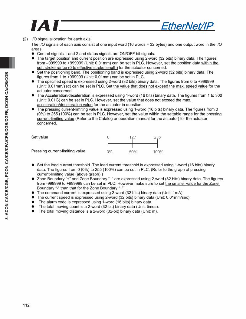
3. A
CO
N-C
A/C
B/C
GB
, PC
ON
-CA
/CB
/CFA
/CFB
/CG
B/C
GFB
, DC
ON
-CA
/CB
/CG
B
112
(2) I/O signal allocation for each axis
The I/O signals of each axis consist of one input word (16 words = 32 bytes) and one output word in the I/O areas.
Control signals 1 and 2 and status signals are ON/OFF bit signals. The target position and current position are expressed using 2-word (32 bits) binary data. The figures
from –999999 to +999999 (Unit: 0.01mm) can be set in PLC. However, set the position data within the soft stroke range (0 to effective stroke length) for the actuator concerned.
Set the positioning band. The positioning band is expressed using 2-word (32 bits) binary data. The figures from 1 to +999999 (Unit: 0.01mm) can be set in PLC.
The specified speed is expressed using 2-word (32 bits) binary data. The figures from 0 to +999999 (Unit: 0.01mm/sec) can be set in PLC. Set the value that does not exceed the max. speed value for the actuator concerned.
The Acceleration/deceleration is expressed using 1-word (16 bits) binary data. The figures from 1 to 300 (Unit: 0.01G) can be set in PLC. However, set the value that does not exceed the max. acceleration/deceleration value for the actuator in question.
The pressing current-limiting value is expressed using 1-word (16 bits) binary data. The figures from 0 (0%) to 255 (100%) can be set in PLC. However, set the value within the settable range for the pressing current-limiting value (Refer to the Catalog or operation manual for the actuator) for the actuator concerned.
Set value Pressing current-limiting value
Set the load current threshold. The load current threshold is expressed using 1-word (16 bits) binary data. The figures from 0 (0%) to 255 (100%) can be set in PLC. (Refer to the graph of pressing current-limiting value (above graph).)
Zone Boundary “+” and Zone Boundary “–“ are expressed using 2-word (32 bits) binary data. The figures from -999999 to +999999 can be set in PLC. However make sure to set the smaller value for the Zone Boundary “-“ than that for the Zone Boundary “+”.
The command current is expressed using 2-word (32 bits) binary data (Unit: 1mA). The current speed is expressed using 2-word (32 bits) binary data (Unit: 0.01mm/sec). The alarm code is expressed using 1-word (16 bits) binary data. The total moving count is a 2-word (32-bit) binary data (Unit: times). The total moving distance is a 2-word (32-bit) binary data (Unit: m).
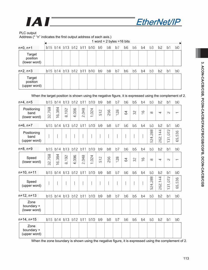
3. AC
ON
-CA
/CB
/CG
B, PC
ON
-CA
/CB
/CFA
/CFB
/CG
B/C
GFB
, DC
ON
-CA
/CB
/CG
B
113
PLC output Address (* “n” indicates the first output address of each axis.)
When the target position is shown using the negative figure, it is expressed using the complement of 2.
When the zone boundary is shown using the negative figure, it is expressed using the complement of 2.
1 word = 2 bytes =16 bits
Target position
(lower word)
Target position
(upper word)
n+2, n+3
n+0, n+1
Positioning band
(lower word)
Positioning band
(upper word)
Speed (lower word)
Zone boundary + (lower word)
Speed (upper word)
Zone boundary +
(upper word)
n+12, n+13
n+10, n+11
n+8, n+9
n+6, n+7
n+4, n+5
n+14, n+15
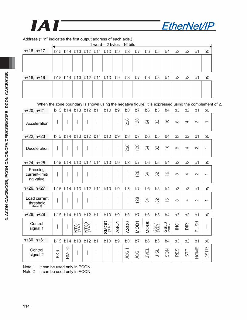
3. A
CO
N-C
A/C
B/C
GB
, PC
ON
-CA
/CB
/CFA
/CFB
/CG
B/C
GFB
, DC
ON
-CA
/CB
/CG
B
114
Address (* “n” indicates the first output address of each axis.)
When the zone boundary is shown using the negative figure, it is expressed using the complement of 2.
Note 1 It can be used only in PCON. Note 2 It can be used only in ACON.
1 word = 2 bytes =16 bits
Control signal 2
Acceleration
Deceleration
Pressing current-limiti
ng value
Load current threshold
(Note 1)
Control signal 1
n+28, n+29
n+26, n+27
n+24, n+25
n+22, n+23
n+20, n+21
n+18, n+19
n+16, n+17
n+30, n+31
AS
O1
AS
O0
MO
D1
SM
OD
(N
ote
1)
MO
D0
NTC
1 (N
ote
2)
NTC
0 (N
ote
2)
GS
L1
(Not
e 2)
GS
L0
(Not
e 2)
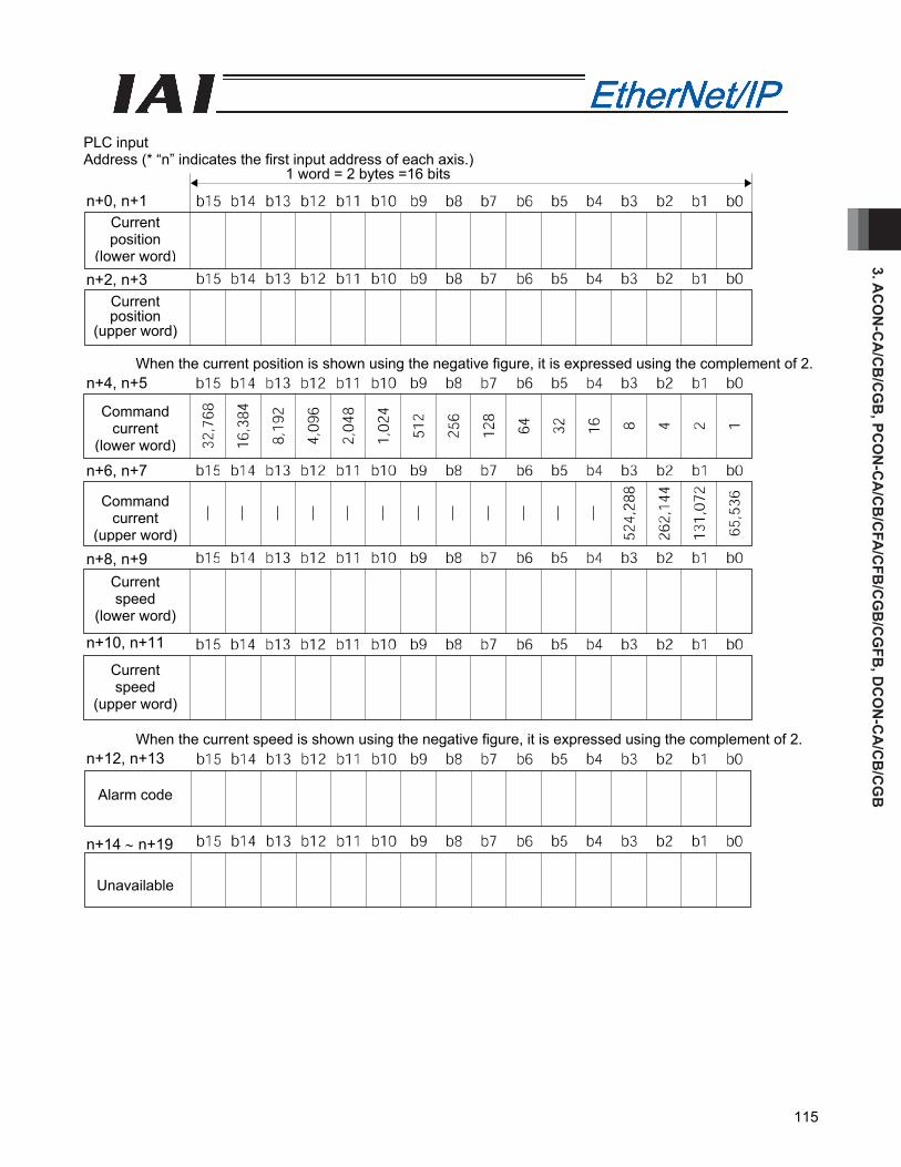
3. AC
ON
-CA
/CB
/CG
B, PC
ON
-CA
/CB
/CFA
/CFB
/CG
B/C
GFB
, DC
ON
-CA
/CB
/CG
B
115
PLC input Address (* “n” indicates the first input address of each axis.)
When the current position is shown using the negative figure, it is expressed using the complement of 2. When the current speed is shown using the negative figure, it is expressed using the complement of 2.
Current position
(lower word)
1 word = 2 bytes =16 bits
n+0, n+1
Current position
(upper word)
n+2, n+3
Command current
(lower word)
n+4, n+5
Command current
(upper word)
n+6, n+7
Current speed
(lower word)
n+8, n+9
Current speed
(upper word)
n+10, n+11
Alarm code
n+12, n+13
Unavailable
n+14 ∼ n+19

3. A
CO
N-C
A/C
B/C
GB
, PC
ON
-CA
/CB
/CFA
/CFB
/CG
B/C
GFB
, DC
ON
-CA
/CB
/CG
B
116
Address (* “n” indicates the first input address of each axis.) 1 word = 2 bytes = 16 bits
n+20, n+21 b15 b14 b13 b12 b11 b10 b9 b8 b7 b6 b5 b4 b3 b2 b1 b0Total moving
count (Slave Word) 32
,768
16,3
84
8,19
2
4,09
6
2,04
8
1,02
4
512
256
128
64
32
16
8 4 2 1
n+22, n+23 b15 b14 b13 b12 b11 b10 b9 b8 b7 b6 b5 b4 b3 b2 b1 b0
Total moving count
(Host Word)
⎯
⎯
⎯
⎯
⎯
⎯
⎯
⎯
⎯
⎯
⎯
⎯
524,
288
262,
144
131,
072
65,5
36
n+24, n+25 b15 b14 b13 b12 b11 b10 b9 b8 b7 b6 b5 b4 b3 b2 b1 b0Total moving
distance (Slave Word) 32
,768
16,3
84
8,19
2
4,09
6
2,04
8
1,02
4
512
256
128
64
32
16
8 4 2 1
n+26, n+27 b15 b14 b13 b12 b11 b10 b9 b8 b7 b6 b5 b4 b3 b2 b1 b0
Total moving distance
(Host Word)
⎯
⎯
⎯
⎯
⎯
⎯
⎯
⎯
⎯
⎯
⎯
⎯
524,
288
262,
144
131,
072
65,5
36
n+28, n+29 b15 b14 b13 b12 b11 b10 b9 b8 b7 b6 b5 b4 b3 b2 b1 b0
Status Signal 1 ⎯
⎯
⎯
⎯
⎯
⎯
⎯
⎯
⎯
⎯
⎯
⎯
⎯
⎯
⎯
ALM
L (N
ote
2)
n+30, n+31 b15 b14 b13 b12 b11 b10 b9 b8 b7 b6 b5 b4 b3 b2 b1 b0
Status Signal 2
EM
GS
PW
R
ZON
E2
ZON
E1
PZO
NE
LOA
D
(Not
e 1)
TRQ
S
(Not
e 1)
RM
DS
GH
MS
PU
SH
PS
FL
SV
ALM
MO
VE
HE
ND
PE
ND
Note 1 It can be used only in PCON. Note 2 For ACON, it can be changed to BALM by the setting in Parameter No. 151.
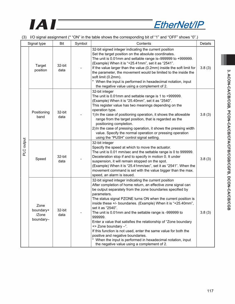
3. AC
ON
-CA
/CB
/CG
B, PC
ON
-CA
/CB
/CFA
/CFB
/CG
B/C
GFB
, DC
ON
-CA
/CB
/CG
B
117
(3) I/O signal assignment (* “ON” in the table shows the corresponding bit of “1” and “OFF” shows “0”.)
Signal type Bit Symbol Contents Details
Target position
32-bit data -
32-bit signed integer indicating the current position Set the target position on the absolute coordinates. The unit is 0.01mm and settable range is–999999 to +999999. (Example) When it is “+25.41mm”, set it as “2541”. If the value larger than the value (0.2mm) inside the soft limit for the parameter, the movement would be limited to the inside the soft limit (0.2mm). * When the input is performed in hexadecimal notation, input
the negative value using a complement of 2.
3.8 (3)
Positioning band
32-bit data -
32-bit integer The unit is 0.01mm and settable range is 1 to +999999. (Example) When it is “25.40mm”, set it as “2540”. This register value has two meanings depending on the operation type. 1) In the case of positioning operation, it shows the allowable
range from the target position, that is regarded as the positioning completion.
2) In the case of pressing operation, it shows the pressing width value. Specify the normal operation or pressing operation using the “PUSH” control signal setting.
3.8 (3)
Speed 32-bit data -
32-bit integer Specify the speed at which to move the actuator. The unit is 0.01 mm/sec and the settable range is 0 to 999999. Deceleration stop if and to specify in motion 0. It under suspension, it will remain stopped on the spot. (Example) When it is “25.41mm/sec”, set it as “2541”. When the movement command is set with the value bigger than the max. speed, an alarm is issued.
3.8 (3)
PLC
out
put
Zone boundary+
/Zone boundary–
32-bit data -
32-bit signed integer indicating the current position After completion of home return, an effective zone signal can be output separately from the zone boundaries specified by parameters. The status signal PZONE turns ON when the current position is inside these +/- boundaries. (Example) When it is “+25.40mm”, set it as “2540”. The unit is 0.01mm and the settable range is -999999 to 999999. Enter a value that satisfies the relationship of “Zone boundary +> Zone boundary –”. If this function is not used, enter the same value for both the positive and negative boundaries. * When the input is performed in hexadecimal notation, input
the negative value using a complement of 2.
3.8 (3)
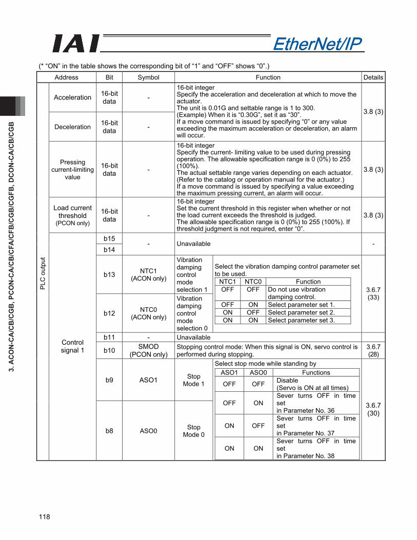
3. A
CO
N-C
A/C
B/C
GB
, PC
ON
-CA
/CB
/CFA
/CFB
/CG
B/C
GFB
, DC
ON
-CA
/CB
/CG
B
118
(* “ON” in the table shows the corresponding bit of “1” and “OFF” shows “0”.)
Address Bit Symbol Function Details
Acceleration 16-bit data -
Deceleration 16-bit data -
16-bit integer Specify the acceleration and deceleration at which to move the actuator. The unit is 0.01G and settable range is 1 to 300. (Example) When it is “0.30G”, set it as “30”. If a move command is issued by specifying “0” or any value exceeding the maximum acceleration or deceleration, an alarm will occur.
3.8 (3)
Pressing current-limiting
value
16-bit data -
16-bit integer Specify the current- limiting value to be used during pressing operation. The allowable specification range is 0 (0%) to 255 (100%). The actual settable range varies depending on each actuator. (Refer to the catalog or operation manual for the actuator.) If a move command is issued by specifying a value exceeding the maximum pressing current, an alarm will occur.
3.8 (3)
Load current threshold
(PCON only)
16-bit data -
16-bit integer Set the current threshold in this register when whether or not the load current exceeds the threshold is judged. The allowable specification range is 0 (0%) to 255 (100%). If threshold judgment is not required, enter “0”.
3.8 (3)
b15 b14
- Unavailable -
b13 NTC1 (ACON only)
Vibration damping control mode selection 1
b12 NTC0 (ACON only)
Vibration damping control mode selection 0
Select the vibration damping control parameter set to be used.
NTC1 NTC0 Function OFF OFF Do not use vibration
damping control. OFF ON Select parameter set 1. ON OFF Select parameter set 2. ON ON Select parameter set 3.
3.6.7 (33)
b11 - Unavailable
b10 SMOD (PCON only)
Stopping control mode: When this signal is ON, servo control is performed during stopping.
3.6.7 (28)
b9 ASO1 Stop Mode 1
PLC
out
put
Control signal 1
b8 ASO0 Stop Mode 0
Select stop mode while standing by ASO1 ASO0 Functions
OFF OFF Disable (Servo is ON at all times)
OFF ON Sever turns OFF in time set in Parameter No. 36
ON OFF Sever turns OFF in time set in Parameter No. 37
ON ON Sever turns OFF in time set in Parameter No. 38
3.6.7 (30)
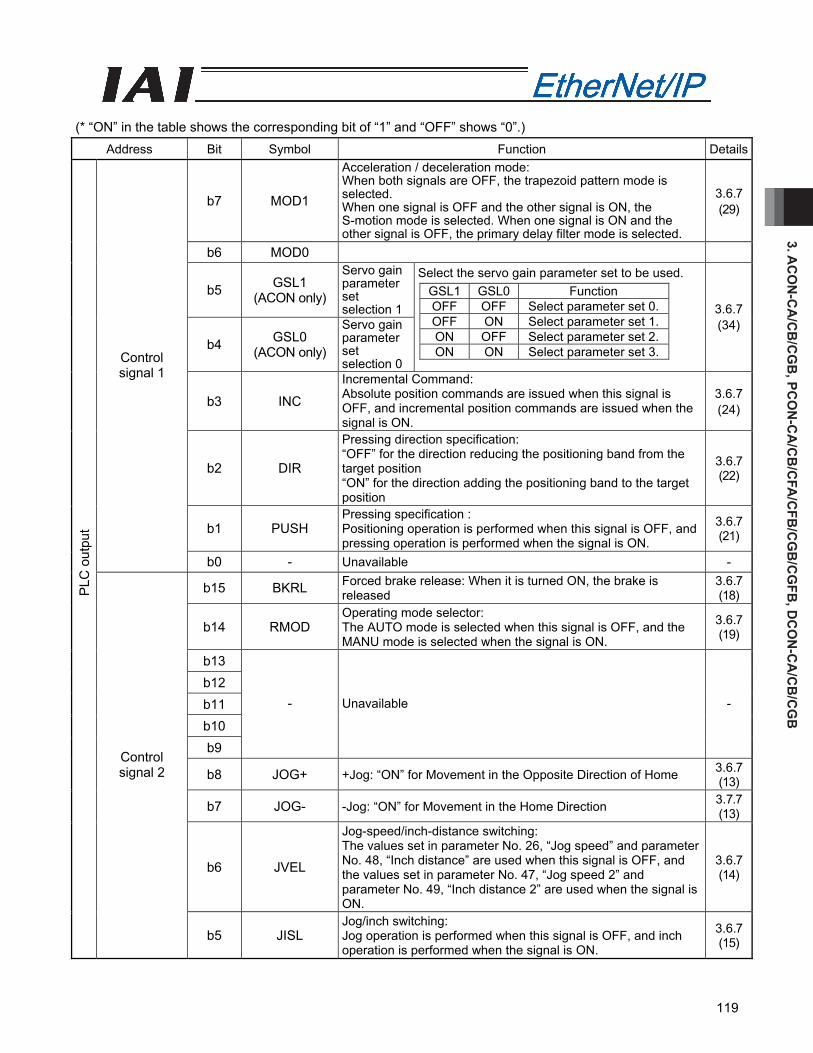
3. AC
ON
-CA
/CB
/CG
B, PC
ON
-CA
/CB
/CFA
/CFB
/CG
B/C
GFB
, DC
ON
-CA
/CB
/CG
B
119
(* “ON” in the table shows the corresponding bit of “1” and “OFF” shows “0”.)
Address Bit Symbol Function Details
b7 MOD1
Acceleration / deceleration mode: When both signals are OFF, the trapezoid pattern mode is selected. When one signal is OFF and the other signal is ON, the S-motion mode is selected. When one signal is ON and the other signal is OFF, the primary delay filter mode is selected.
3.6.7 (29)
b6 MOD0
b5 GSL1 (ACON only)
Servo gain parameter set selection 1
b4 GSL0 (ACON only)
Servo gain parameter set selection 0
Select the servo gain parameter set to be used.
3.6.7 (34)
b3 INC
Incremental Command: Absolute position commands are issued when this signal is OFF, and incremental position commands are issued when the signal is ON.
3.6.7 (24)
b2 DIR
Pressing direction specification: “OFF” for the direction reducing the positioning band from the target position “ON” for the direction adding the positioning band to the target position
3.6.7 (22)
b1 PUSH Pressing specification : Positioning operation is performed when this signal is OFF, and pressing operation is performed when the signal is ON.
3.6.7 (21)
Control signal 1
b0 - Unavailable -
b15 BKRL Forced brake release: When it is turned ON, the brake is released
3.6.7 (18)
b14 RMOD Operating mode selector: The AUTO mode is selected when this signal is OFF, and the MANU mode is selected when the signal is ON.
3.6.7 (19)
b13 b12 b11 b10 b9
- Unavailable -
b8 JOG+ +Jog: “ON” for Movement in the Opposite Direction of Home 3.6.7 (13)
b7 JOG- -Jog: “ON” for Movement in the Home Direction 3.7.7 (13)
b6 JVEL
Jog-speed/inch-distance switching: The values set in parameter No. 26, “Jog speed” and parameter No. 48, “Inch distance” are used when this signal is OFF, and the values set in parameter No. 47, “Jog speed 2” and parameter No. 49, “Inch distance 2” are used when the signal is ON.
3.6.7 (14)
PLC
out
put
Control signal 2
b5 JISL Jog/inch switching: Jog operation is performed when this signal is OFF, and inch operation is performed when the signal is ON.
3.6.7 (15)
GSL1 GSL0 Function OFF OFF Select parameter set 0.OFF ON Select parameter set 1.ON OFF Select parameter set 2.ON ON Select parameter set 3.
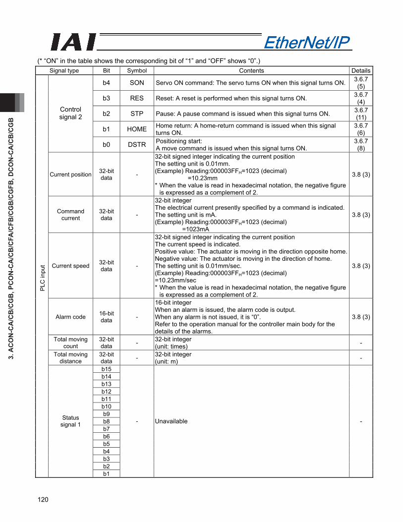
3. A
CO
N-C
A/C
B/C
GB
, PC
ON
-CA
/CB
/CFA
/CFB
/CG
B/C
GFB
, DC
ON
-CA
/CB
/CG
B
120
(* “ON” in the table shows the corresponding bit of “1” and “OFF” shows “0”.)
Signal type Bit Symbol Contents Details
b4 SON Servo ON command: The servo turns ON when this signal turns ON. 3.6.7 (5)
b3 RES Reset: A reset is performed when this signal turns ON. 3.6.7 (4)
b2 STP Pause: A pause command is issued when this signal turns ON. 3.6.7 (11)
b1 HOME Home return: A home-return command is issued when this signal turns ON.
3.6.7 (6)
Control signal 2
b0 DSTR Positioning start: A move command is issued when this signal turns ON.
3.6.7 (8)
Current position 32-bit data -
32-bit signed integer indicating the current position The setting unit is 0.01mm. (Example) Reading:000003FFH=1023 (decimal) =10.23mm * When the value is read in hexadecimal notation, the negative figure
is expressed as a complement of 2.
3.8 (3)
Command current
32-bit data -
32-bit integer The electrical current presently specified by a command is indicated.The setting unit is mA. (Example) Reading:000003FFH=1023 (decimal) =1023mA
3.8 (3)
Current speed 32-bit data -
32-bit signed integer indicating the current position The current speed is indicated. Positive value: The actuator is moving in the direction opposite home.Negative value: The actuator is moving in the direction of home. The setting unit is 0.01mm/sec. (Example) Reading:000003FFH=1023 (decimal) =10.23mm/sec * When the value is read in hexadecimal notation, the negative figure
is expressed as a complement of 2.
3.8 (3)
Alarm code 16-bit data -
16-bit integer When an alarm is issued, the alarm code is output. When any alarm is not issued, it is “0”. Refer to the operation manual for the controller main body for the details of the alarms.
3.8 (3)
Total moving count
32-bit data - 32-bit integer
(unit: times) -
Total moving distance
32-bit data - 32-bit integer
(unit: m) -
b15 b14 b13 b12 b11 b10 b9 b8 b7 b6 b5 b4 b3 b2
PLC
inpu
t
Status signal 1
b1
- Unavailable -
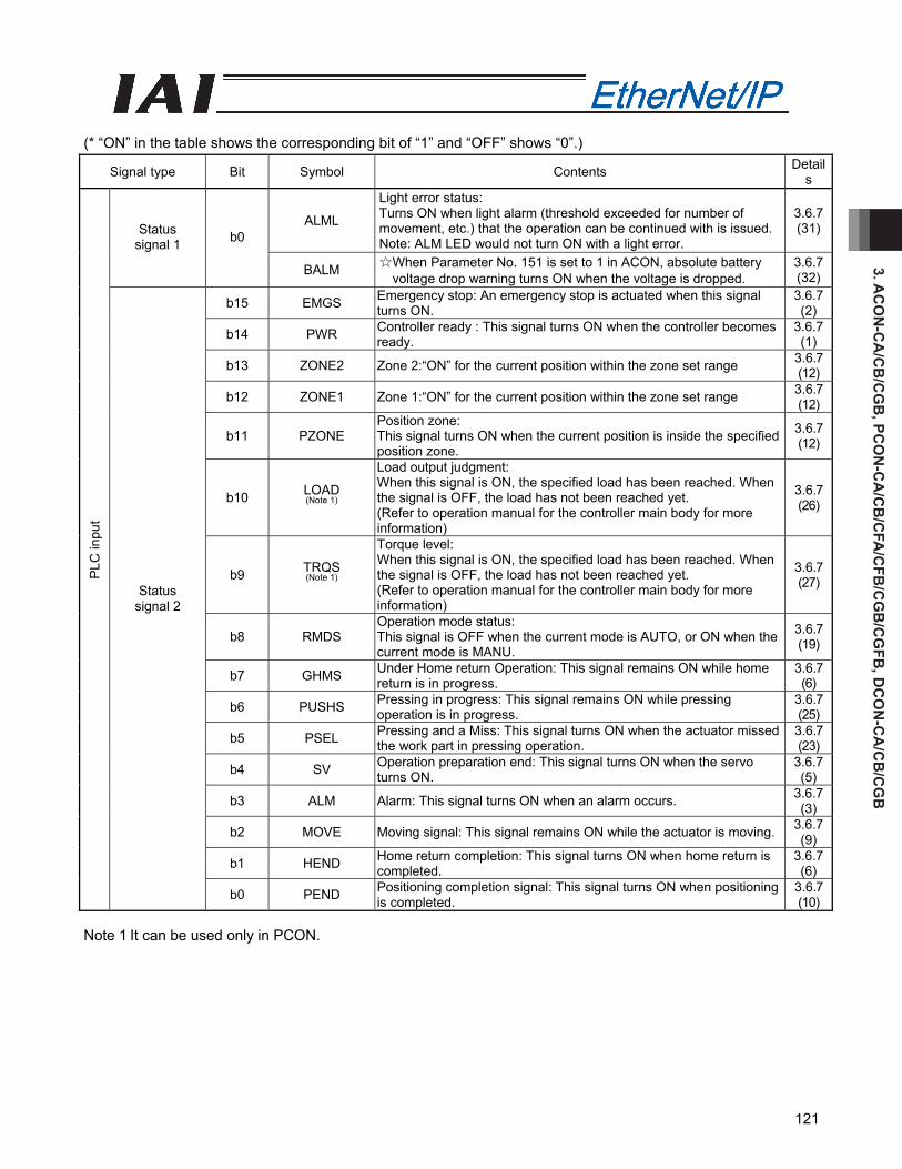
3. AC
ON
-CA
/CB
/CG
B, PC
ON
-CA
/CB
/CFA
/CFB
/CG
B/C
GFB
, DC
ON
-CA
/CB
/CG
B
121
(* “ON” in the table shows the corresponding bit of “1” and “OFF” shows “0”.)
Signal type Bit Symbol Contents Details
ALML
Light error status: Turns ON when light alarm (threshold exceeded for number of movement, etc.) that the operation can be continued with is issued.Note: ALM LED would not turn ON with a light error.
3.6.7 (31)Status
signal 1 b0
BALM ☆When Parameter No. 151 is set to 1 in ACON, absolute battery voltage drop warning turns ON when the voltage is dropped.
3.6.7 (32)
b15 EMGS Emergency stop: An emergency stop is actuated when this signal turns ON.
3.6.7 (2)
b14 PWR Controller ready : This signal turns ON when the controller becomes ready.
3.6.7 (1)
b13 ZONE2 Zone 2:“ON” for the current position within the zone set range 3.6.7 (12)
b12 ZONE1 Zone 1:“ON” for the current position within the zone set range 3.6.7 (12)
b11 PZONE Position zone: This signal turns ON when the current position is inside the specified position zone.
3.6.7 (12)
b10 LOAD (Note 1)
Load output judgment: When this signal is ON, the specified load has been reached. When the signal is OFF, the load has not been reached yet. (Refer to operation manual for the controller main body for more information)
3.6.7 (26)
b9 TRQS (Note 1)
Torque level: When this signal is ON, the specified load has been reached. When the signal is OFF, the load has not been reached yet. (Refer to operation manual for the controller main body for more information)
3.6.7 (27)
b8 RMDS Operation mode status: This signal is OFF when the current mode is AUTO, or ON when the current mode is MANU.
3.6.7 (19)
b7 GHMS Under Home return Operation: This signal remains ON while home return is in progress.
3.6.7 (6)
b6 PUSHS Pressing in progress: This signal remains ON while pressing operation is in progress.
3.6.7 (25)
b5 PSEL Pressing and a Miss: This signal turns ON when the actuator missed the work part in pressing operation.
3.6.7 (23)
b4 SV Operation preparation end: This signal turns ON when the servo turns ON.
3.6.7 (5)
b3 ALM Alarm: This signal turns ON when an alarm occurs. 3.6.7 (3)
b2 MOVE Moving signal: This signal remains ON while the actuator is moving. 3.6.7 (9)
b1 HEND Home return completion: This signal turns ON when home return is completed.
3.6.7 (6)
PLC
inpu
t
Status signal 2
b0 PEND Positioning completion signal: This signal turns ON when positioning is completed.
3.6.7 (10)
Note 1 It can be used only in PCON.
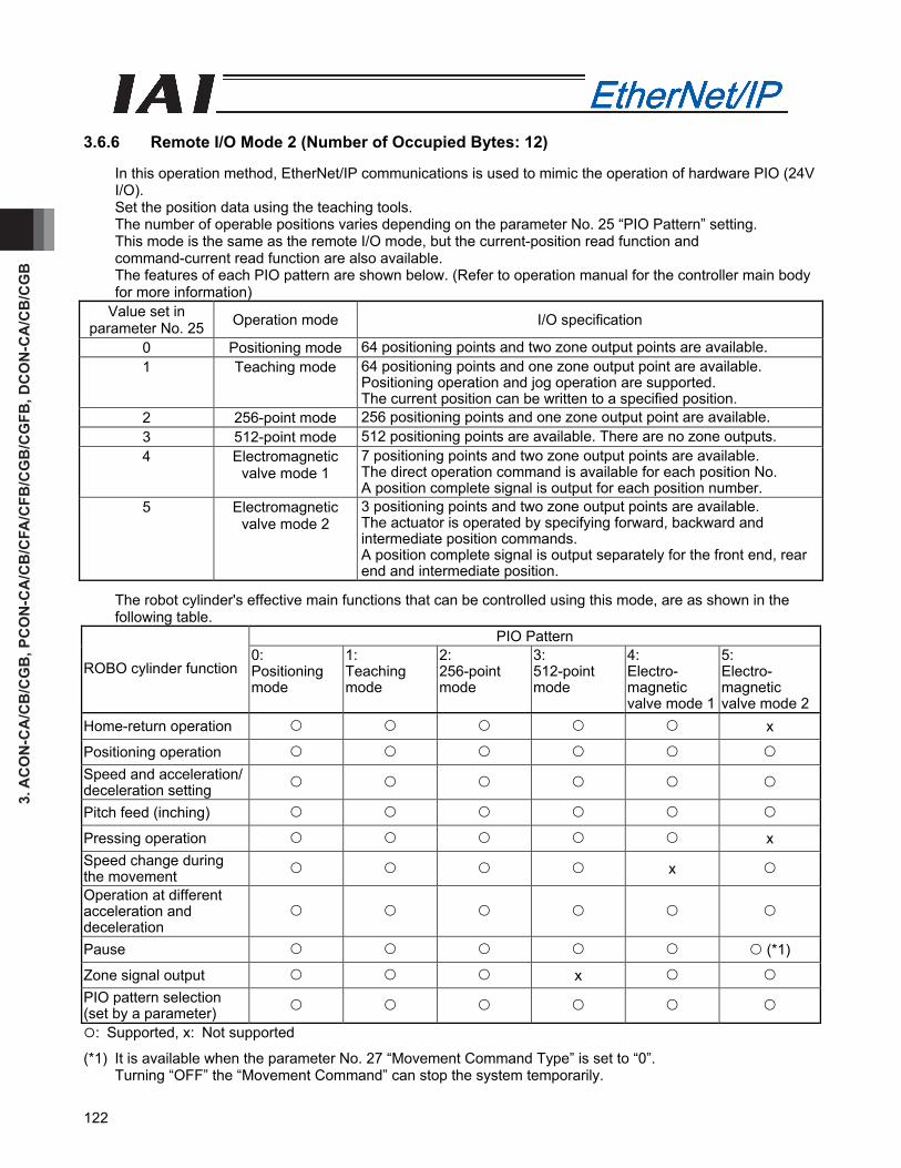
3. A
CO
N-C
A/C
B/C
GB
, PC
ON
-CA
/CB
/CFA
/CFB
/CG
B/C
GFB
, DC
ON
-CA
/CB
/CG
B
122
3.6.6 Remote I/O Mode 2 (Number of Occupied Bytes: 12)
In this operation method, EtherNet/IP communications is used to mimic the operation of hardware PIO (24V I/O). Set the position data using the teaching tools. The number of operable positions varies depending on the parameter No. 25 “PIO Pattern” setting. This mode is the same as the remote I/O mode, but the current-position read function and command-current read function are also available. The features of each PIO pattern are shown below. (Refer to operation manual for the controller main body for more information)
Value set in parameter No. 25 Operation mode I/O specification
0 Positioning mode 64 positioning points and two zone output points are available. 1 Teaching mode 64 positioning points and one zone output point are available.
Positioning operation and jog operation are supported. The current position can be written to a specified position.
2 256-point mode 256 positioning points and one zone output point are available. 3 512-point mode 512 positioning points are available. There are no zone outputs. 4 Electromagnetic
valve mode 1 7 positioning points and two zone output points are available. The direct operation command is available for each position No. A position complete signal is output for each position number.
5 Electromagnetic valve mode 2
3 positioning points and two zone output points are available. The actuator is operated by specifying forward, backward and intermediate position commands. A position complete signal is output separately for the front end, rear end and intermediate position.
The robot cylinder's effective main functions that can be controlled using this mode, are as shown in the following table.
PIO Pattern
ROBO cylinder function 0: Positioning mode
1: Teaching mode
2: 256-point mode
3: 512-point mode
4: Electro- magnetic valve mode 1
5: Electro- magnetic valve mode 2
Home-return operation x
Positioning operation Speed and acceleration/ deceleration setting
Pitch feed (inching)
Pressing operation x Speed change during the movement x
Operation at different acceleration and deceleration
Pause (*1)
Zone signal output x PIO pattern selection (set by a parameter)
: Supported, x: Not supported
(*1) It is available when the parameter No. 27 “Movement Command Type” is set to “0”. Turning “OFF” the “Movement Command” can stop the system temporarily.

3. AC
ON
-CA
/CB
/CG
B, PC
ON
-CA
/CB
/CFA
/CFB
/CG
B/C
GFB
, DC
ON
-CA
/CB
/CG
B
123
(1) PLC address configuration (* “n” indicates the first address of each axis.)
Parameter No.84
IAI controllers side DI and input register
PLC side output address (bytes)
IAI controllers side DO and output register
PLC side input address (bytes)
Port No.0 to 15 n, n+1 Port No.0 to 15 n, n+1 n+2, n+3 Occupied area n+2, n+3 n+4, n+5 n+4, n+5 n+6, n+7
Current position n+6, n+7
n+8, n+9 n+8, n+9
4 Occupied area
n+10, n+11 Command current
n+10, n+11
(Note) The areas denoted by Occupied area cannot be used for any other purpose. Also, exercise caution to avoid node address duplication.
(2) I/O signal allocation for each axis
The I/O signals of each axis consist of 6 input words (channels) and 6 output words (6 words=12 bytes) in the I/O areas.
The areas controlled by port number are controlled using ON/OFF bit signals. The current position is a 2-word (32-bit) binary data (unit: 0.01 mm). The command current is expressed using 2-word (32 bits) binary data (Unit: 1mA).
PLC output Address (* “n” indicates the first output address of each axis.)
1 word = 2 bytes =16 bits
Controller input port number
n+0、n+1n+0, n+1
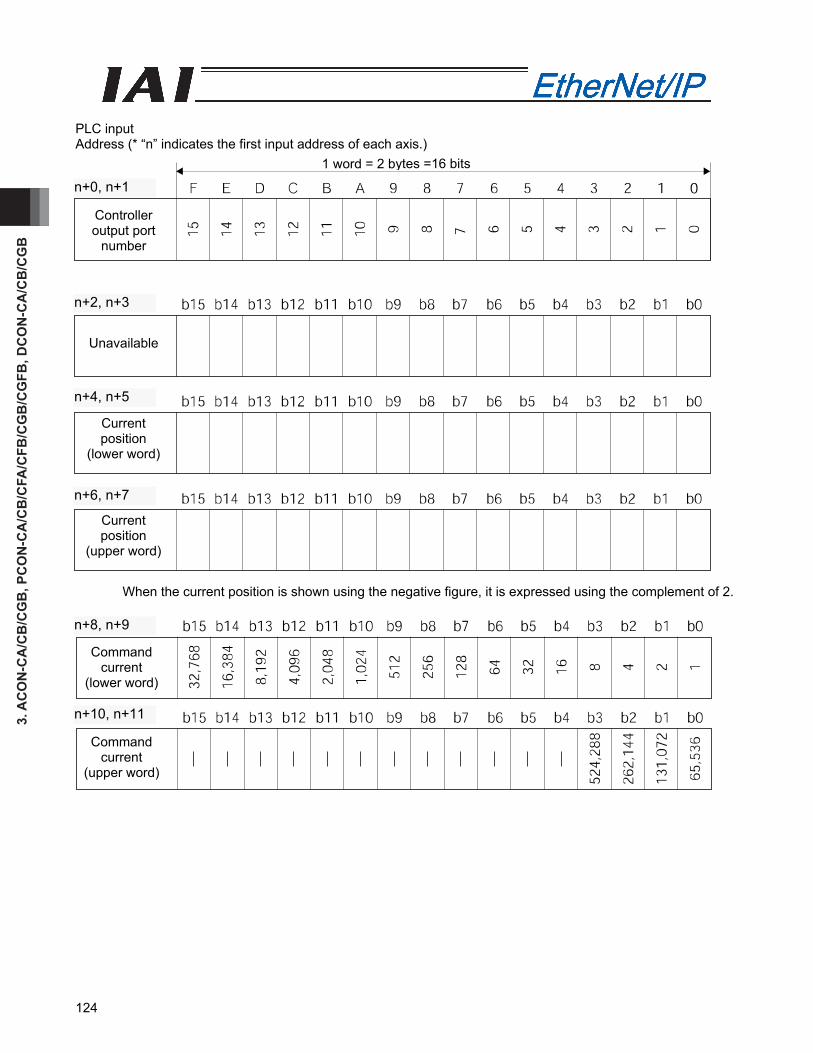
3. A
CO
N-C
A/C
B/C
GB
, PC
ON
-CA
/CB
/CFA
/CFB
/CG
B/C
GFB
, DC
ON
-CA
/CB
/CG
B
124
PLC input Address (* “n” indicates the first input address of each axis.)
When the current position is shown using the negative figure, it is expressed using the complement of 2.
1 word = 2 bytes =16 bits
Controller output port
number
Unavailable
Current position
(lower word)
Current position
(upper word)
n+6, n+7
n+4, n+5
n+2, n+3
n+0, n+1
Command current
(upper word)
Command current
(lower word)
n+10, n+11
n+8, n+9
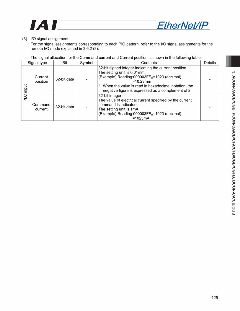
3. AC
ON
-CA
/CB
/CG
B, PC
ON
-CA
/CB
/CFA
/CFB
/CG
B/C
GFB
, DC
ON
-CA
/CB
/CG
B
125
(3) I/O signal assignment
For the signal assignments corresponding to each PIO pattern, refer to the I/O signal assignments for the remote I/O mode explained in 3.6.2 (3).
The signal allocation for the Command current and Current position is shown in the following table.
Signal type Bit Symbol Contents Details
Current position 32-bit data -
32-bit signed integer indicating the current position The setting unit is 0.01mm. (Example) Reading:000003FFH=1023 (decimal)
=10.23mm * When the value is read in hexadecimal notation, the
negative figure is expressed as a complement of 2.
-
PLC
inpu
t
Command current 32-bit data -
32-bit integer The value of electrical current specified by the current command is indicated. The setting unit is 1mA. (Example) Reading:000003FFH=1023 (decimal)
=1023mA
-
3. A
CO
N-C
A/C
B/C
GB
, PC
ON
-CA
/CB
/CFA
/CFB
/CG
B/C
GFB
, DC
ON
-CA
/CB
/CG
B
126
3.6.7 I/O Signal Controls and Function
* ON indicates that the applicable bit signal is “1”, while OFF indicates that the bit signal is “0”. The I/O control and functions used in the Position/Simplified Direct Value Mode, Half direct value mode and Full direct value mode, are described as follows. For the I/O signals for the Remote I/O mode and Remote I/O mode 2, refer to the controller’s operational manual.
(1) Controller ready (PWR) PLC input signal
When the controller can control the system after the power is applied, it is turned “ON”. ■ Function Regardless of the alarm or servo conditions, when the controller initialization is completed normally after the power is applied and the controller can control the system, it is turned “ON”. Even in the alarm condition, when the controller can control the system, it is turned “ON”.
(2) Emergency stop (EMGS) PLC input signal
When the controller is stopped in an emergency, it is turned “ON”. ■ Function When the controller is stopped in an emergency (motor driving power is cut off), it is turned “ON”. When the emergency stop status is cleared, it is turned “OFF”.
(3) Alarm (ALM) PLC input signal
When any error is detected using the controller protection circuit (function), it is turned “ON”. ■ Function When any error is detected and the protection circuit (function) is activated, this signal is turned “ON”. When the cause of the alarm is eliminated and the reset signal is turned “ON”, the alarm is turned “OFF” in the case that it is the alarm with the operation cancellation level. (In the case of the alarm with the cold start level, cycling of the power is required) When the alarm is detected, the Status Indicator LED (Refer to 3.3, "EtherNet/IP Interface”) on the front surface of the controller illuminates in red.
(4) Reset (RES) PLC output signal
This signal has two functions. It can reset the controller alarm and cancel the reminder for planned movements during pause conditions. ■ Function
[1] When this signal is turned ON from OFF condition after eliminating the cause of the alarm during the alarm output, the alarm (ALM) signal can be reset. (In the case of the alarm with the cold start level, cycling of the power is required)
[2] When this signal is turned ON from OFF condition during the pause condition, the reminder of the planned movement left can be cancelled.
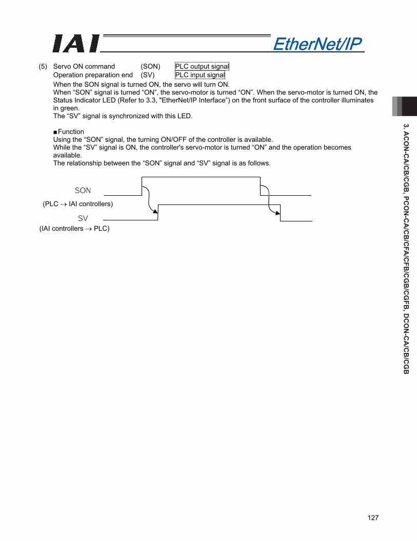
3. AC
ON
-CA
/CB
/CG
B, PC
ON
-CA
/CB
/CFA
/CFB
/CG
B/C
GFB
, DC
ON
-CA
/CB
/CG
B
127
(5) Servo ON command (SON) PLC output signal
Operation preparation end (SV) PLC input signal When the SON signal is turned ON, the servo will turn ON. When “SON” signal is turned “ON”, the servo-motor is turned “ON”. When the servo-motor is turned ON, the Status Indicator LED (Refer to 3.3, "EtherNet/IP Interface”) on the front surface of the controller illuminates in green. The “SV” signal is synchronized with this LED.
■ Function Using the “SON” signal, the turning ON/OFF of the controller is available. While the “SV” signal is ON, the controller's servo-motor is turned “ON” and the operation becomes available. The relationship between the “SON” signal and “SV” signal is as follows.
(PLC → IAI controllers)
(IAI controllers → PLC)

3. A
CO
N-C
A/C
B/C
GB
, PC
ON
-CA
/CB
/CFA
/CFB
/CG
B/C
GFB
, DC
ON
-CA
/CB
/CG
B
128
(6) Home return (HOME) PLC output signal
Home return completion (HEND) PLC input signal Under home return operation (GHMS) PLC input signal When the “HOME” signal is turned “ON”, this command is processed at the startup (ON edge), and the home return operation is performed automatically. During the home return operation, the “GHMS” signal is turned “ON”. When the “HEND” signal is turned “ON”, turn “OFF” the “HOME” signal. Once the “HEND” signal is turned “ON”, it can not be turned “OFF” until the power is turned “OFF” or the “HOME” signal is input again. Once the HEND signal is turned ON, it can not be turned OFF until the power is turned OFF or the HOME signal is input again. Even after the completion of the home return operation, when the “HOME” signal is turned “ON”, the home return operation can be performed.
Caution: In the Remote I/O mode, Remote I/O mode 2 and Position/Simplified Direct Value Mode, when the positioning command is issued without performing the home return operation after the power is applied, the positioning is performed after the automatic home return operation. Exercise caution that in the half direct mode or full direct mode, issuing a positioning command to a given position following the power on, without performing a home return first, will generate an alarm “Error Code 83: ALARM HOME ABS (absolute position move command when home return is not yet completed)” (operation-reset alarm).
(PLC → IAI controllers)
(IAI controllers → PLC)
Actuator operation
Mechanical end Stop at the home position
(IAI controllers → PLC)
(IAI controllers → PLC)
(IAI controllers → PLC)
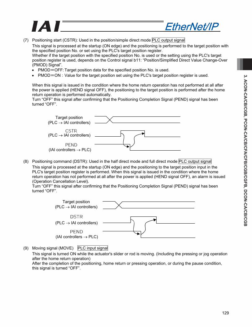
3. AC
ON
-CA
/CB
/CG
B, PC
ON
-CA
/CB
/CFA
/CFB
/CG
B/C
GFB
, DC
ON
-CA
/CB
/CG
B
129
(7) Positioning start (CSTR): Used in the position/simple direct mode PLC output signal
This signal is processed at the startup (ON edge) and the positioning is performed to the target position with the specified position No. or set using the PLC's target position register. Whether if the target position with the specified position No. is used or the setting using the PLC's target position register is used, depends on the Control signal b11: “Position/Simplified Direct Value Change-Over (PMOD) Signal”. • PMOD=OFF: Target position data for the specified position No. is used. • PMOD=ON : Value for the target position set using the PLC's target position register is used. When this signal is issued in the condition where the home return operation has not performed at all after the power is applied (HEND signal OFF), the positioning to the target position is performed after the home return operation is performed automatically. Turn “OFF” this signal after confirming that the Positioning Completion Signal (PEND) signal has been turned “OFF”.
(8) Positioning command (DSTR): Used in the half direct mode and full direct mode PLC output signal
This signal is processed at the startup (ON edge) and the positioning to the target position input in the PLC's target position register is performed. When this signal is issued in the condition where the home return operation has not performed at all after the power is applied (HEND signal OFF), an alarm is issued (Operation Cancellation Level). Turn “OFF” this signal after confirming that the Positioning Completion Signal (PEND) signal has been turned “OFF”.
(9) Moving signal (MOVE) PLC input signal
This signal is turned ON while the actuator's slider or rod is moving. (Including the pressing or jog operation after the home return operation) After the completion of the positioning, home return or pressing operation, or during the pause condition, this signal is turned “OFF”.
Target position (PLC → IAI controllers)
(PLC → IAI controllers)
(IAI controllers → PLC)
Target position (PLC → IAI controllers)
(PLC → IAI controllers)
(IAI controllers → PLC)
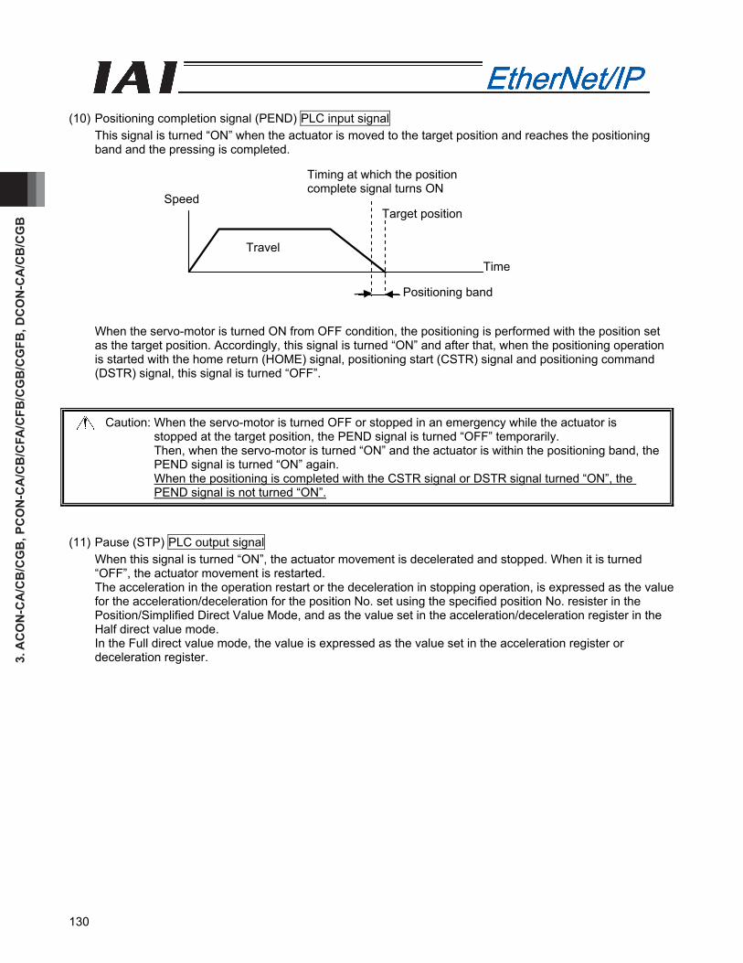
3. A
CO
N-C
A/C
B/C
GB
, PC
ON
-CA
/CB
/CFA
/CFB
/CG
B/C
GFB
, DC
ON
-CA
/CB
/CG
B
130
Travel
Speed
Positioning band
Time
Target position
Timing at which the position complete signal turns ON
(10) Positioning completion signal (PEND) PLC input signal
This signal is turned “ON” when the actuator is moved to the target position and reaches the positioning band and the pressing is completed.
When the servo-motor is turned ON from OFF condition, the positioning is performed with the position set as the target position. Accordingly, this signal is turned “ON” and after that, when the positioning operation is started with the home return (HOME) signal, positioning start (CSTR) signal and positioning command (DSTR) signal, this signal is turned “OFF”.
Caution: When the servo-motor is turned OFF or stopped in an emergency while the actuator is stopped at the target position, the PEND signal is turned “OFF” temporarily. Then, when the servo-motor is turned “ON” and the actuator is within the positioning band, the PEND signal is turned “ON” again. When the positioning is completed with the CSTR signal or DSTR signal turned “ON”, the PEND signal is not turned “ON”.
(11) Pause (STP) PLC output signal
When this signal is turned “ON”, the actuator movement is decelerated and stopped. When it is turned “OFF”, the actuator movement is restarted. The acceleration in the operation restart or the deceleration in stopping operation, is expressed as the value for the acceleration/deceleration for the position No. set using the specified position No. resister in the Position/Simplified Direct Value Mode, and as the value set in the acceleration/deceleration register in the Half direct value mode. In the Full direct value mode, the value is expressed as the value set in the acceleration register or deceleration register.
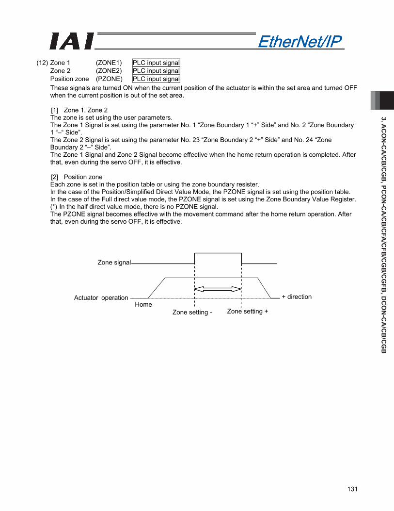
3. AC
ON
-CA
/CB
/CG
B, PC
ON
-CA
/CB
/CFA
/CFB
/CG
B/C
GFB
, DC
ON
-CA
/CB
/CG
B
131
Zone signal
+ direction Actuator operation Home
Zone setting - Zone setting +
(12) Zone 1 (ZONE1) PLC input signal
Zone 2 (ZONE2) PLC input signal Position zone (PZONE) PLC input signal These signals are turned ON when the current position of the actuator is within the set area and turned OFF when the current position is out of the set area. [1] Zone 1, Zone 2 The zone is set using the user parameters. The Zone 1 Signal is set using the parameter No. 1 “Zone Boundary 1 “+” Side” and No. 2 “Zone Boundary 1 “–“ Side”. The Zone 2 Signal is set using the parameter No. 23 “Zone Boundary 2 “+” Side” and No. 24 “Zone Boundary 2 “–“ Side”. The Zone 1 Signal and Zone 2 Signal become effective when the home return operation is completed. After that, even during the servo OFF, it is effective. [2] Position zone Each zone is set in the position table or using the zone boundary resister. In the case of the Position/Simplified Direct Value Mode, the PZONE signal is set using the position table. In the case of the Full direct value mode, the PZONE signal is set using the Zone Boundary Value Register. (*) In the half direct value mode, there is no PZONE signal. The PZONE signal becomes effective with the movement command after the home return operation. After that, even during the servo OFF, it is effective.

3. A
CO
N-C
A/C
B/C
GB
, PC
ON
-CA
/CB
/CFA
/CFB
/CG
B/C
GFB
, DC
ON
-CA
/CB
/CG
B
132
(13) +Jog (JOG+) PLC output signal
–Jog (JOG–) PLC output signal This signal is the command for the jog operation startup or inching operation startup. If a + command is issued, the actuator will operate in the direction opposite home. When a – command is issued, the actuator will operate in the direction of home. [1] Jog operation Jog operation can be performed when the jog/inch switching (JISL) signal is OFF. While the “JOG+” is turned “ON”, the movement direction is to the opposite of the home and when it is turned “OFF”, the actuator is decelerated and stopped. While the JOG – is ON, the actuator will operate in the direction of home and when it is turned OFF, it is decelerated to a stop. The operation is performed based on the set values of the following parameters. • The speed is based on the parameter value specified using the Jog Speed/Inching Distance
Change-Over (JVEL) signal. If the JVEL signal is OFF, the actuator operates according to parameter No. 26, “PIO jog speed”. If the JVEL signal is ON, the actuator operates according to parameter No. 47, “PIO jog speed 2”.
• The acceleration/deceleration conforms to the rate acceleration/deceleration (the specific value varies depending on the actuator).
• When both the JOG+ and JOG- signals are turned “ON”, the actuator is decelerated and stopped. [2] Inch operation The inching operation is available while the JISL signal is turned “ON”. Once it is turned “ON”, the actuator is moved as much as the inching distance. When the JOG+ is turned “ON”, the movement is to the opposite of the home and when the JOG- is turned “ON”, the movement is to the home. The operation is performed based on the set values of the following parameters. • The speed conforms to the value of the parameter specified by the JVEL signal.
If the JVEL signal is OFF, the actuator operates according to parameter No. 26, “PIO jog speed”. If the JVEL signal is ON, the actuator operates according to parameter No. 47, “PIO jog speed 2”.
• The travel conforms to the value of the parameter specified by the JVEL signal. If the JVEL signal is OFF, the actuator operates according to parameter No. 48, “PIO inch distance”. If the JVEL signal is ON, the actuator operates according to parameter No. 49, “PIO inch distance 2”.
• The Acceleration/deceleration is based on the rated acceleration/deceleration (depending on the actuator).
During the normal operation, even when the “+” Jog Signal or “-“ Jog Signal is turned “ON”, the normal operation is continued. (The Jog signal is ignored) In the pause condition, even when the “+” Jog Signal or “-“ Jog Signal is turned “ON”, the actuator is not moved.
(Note) Because the software stroke limit is disabled before the home return operation, the actuator might
run against the mechanism end. Take the greatest care.
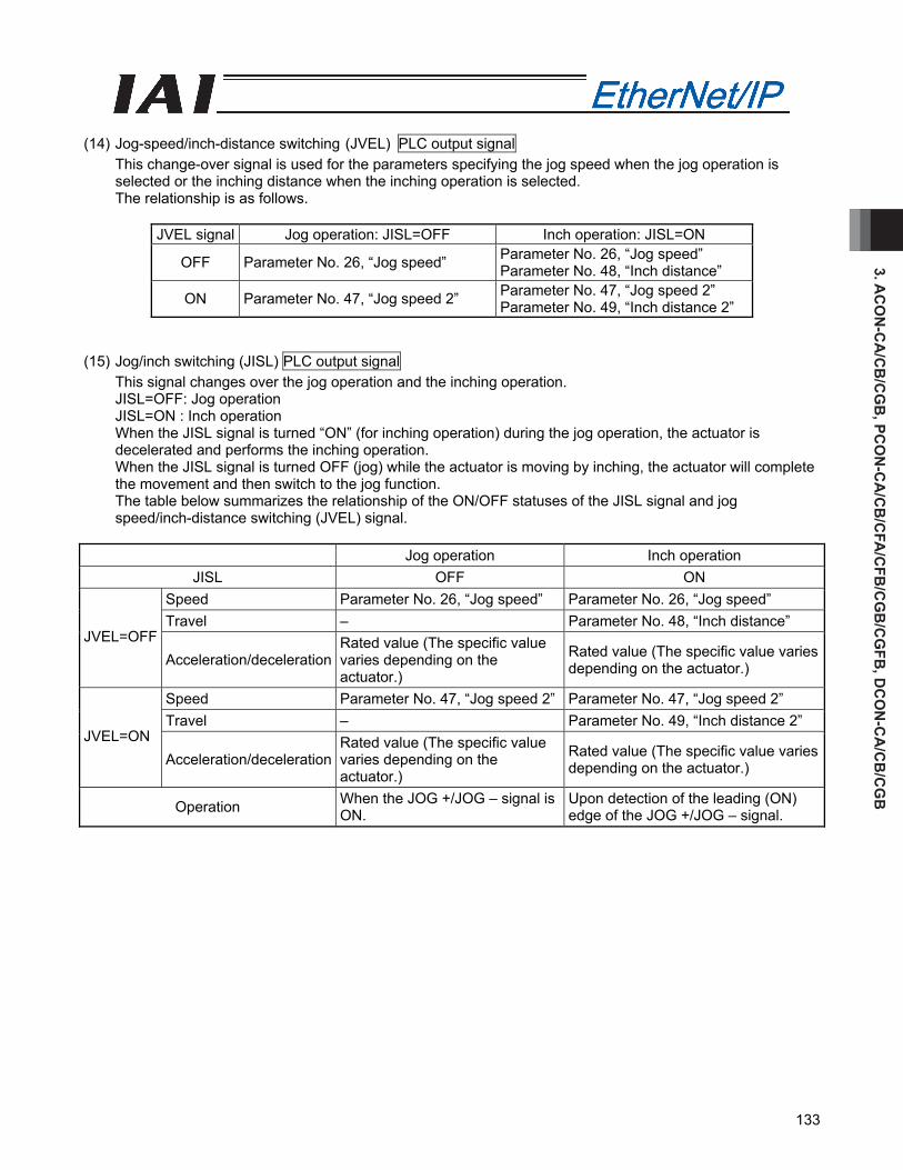
3. AC
ON
-CA
/CB
/CG
B, PC
ON
-CA
/CB
/CFA
/CFB
/CG
B/C
GFB
, DC
ON
-CA
/CB
/CG
B
133
(14) Jog-speed/inch-distance switching (JVEL) PLC output signal
This change-over signal is used for the parameters specifying the jog speed when the jog operation is selected or the inching distance when the inching operation is selected. The relationship is as follows.
JVEL signal Jog operation: JISL=OFF Inch operation: JISL=ON
OFF Parameter No. 26, “Jog speed” Parameter No. 26, “Jog speed” Parameter No. 48, “Inch distance”
ON Parameter No. 47, “Jog speed 2” Parameter No. 47, “Jog speed 2” Parameter No. 49, “Inch distance 2”
(15) Jog/inch switching (JISL) PLC output signal
This signal changes over the jog operation and the inching operation. JISL=OFF: Jog operation JISL=ON : Inch operation When the JISL signal is turned “ON” (for inching operation) during the jog operation, the actuator is decelerated and performs the inching operation. When the JISL signal is turned OFF (jog) while the actuator is moving by inching, the actuator will complete the movement and then switch to the jog function. The table below summarizes the relationship of the ON/OFF statuses of the JISL signal and jog speed/inch-distance switching (JVEL) signal.
Jog operation Inch operation
JISL OFF ON Speed Parameter No. 26, “Jog speed” Parameter No. 26, “Jog speed” Travel – Parameter No. 48, “Inch distance”
JVEL=OFF Acceleration/deceleration
Rated value (The specific value varies depending on the actuator.)
Rated value (The specific value varies depending on the actuator.)
Speed Parameter No. 47, “Jog speed 2” Parameter No. 47, “Jog speed 2” Travel – Parameter No. 49, “Inch distance 2”
JVEL=ON Acceleration/deceleration
Rated value (The specific value varies depending on the actuator.)
Rated value (The specific value varies depending on the actuator.)
Operation When the JOG +/JOG – signal is ON.
Upon detection of the leading (ON) edge of the JOG +/JOG – signal.
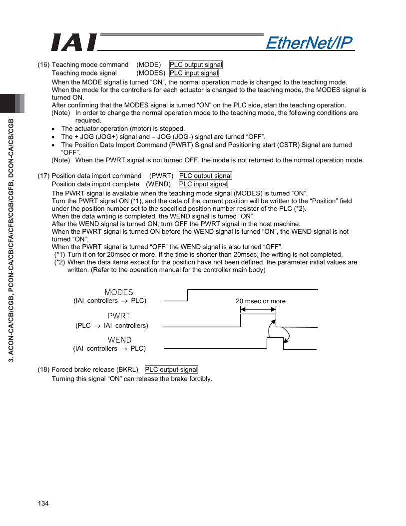
3. A
CO
N-C
A/C
B/C
GB
, PC
ON
-CA
/CB
/CFA
/CFB
/CG
B/C
GFB
, DC
ON
-CA
/CB
/CG
B
134
(16) Teaching mode command (MODE) PLC output signal
Teaching mode signal (MODES) PLC input signal When the MODE signal is turned “ON”, the normal operation mode is changed to the teaching mode. When the mode for the controllers for each actuator is changed to the teaching mode, the MODES signal is turned ON. After confirming that the MODES signal is turned “ON” on the PLC side, start the teaching operation. (Note) In order to change the normal operation mode to the teaching mode, the following conditions are
required. • The actuator operation (motor) is stopped. • The + JOG (JOG+) signal and – JOG (JOG-) signal are turned “OFF”. • The Position Data Import Command (PWRT) Signal and Positioning start (CSTR) Signal are turned
“OFF”. (Note) When the PWRT signal is not turned OFF, the mode is not returned to the normal operation mode.
(17) Position data import command (PWRT) PLC output signal
Position data import complete (WEND) PLC input signal The PWRT signal is available when the teaching mode signal (MODES) is turned “ON”. Turn the PWRT signal ON (*1), and the data of the current position will be written to the “Position” field under the position number set to the specified position number resister of the PLC (*2). When the data writing is completed, the WEND signal is turned “ON”. After the WEND signal is turned ON, turn OFF the PWRT signal in the host machine. When the PWRT signal is turned ON before the WEND signal is turned “ON”, the WEND signal is not turned “ON”. When the PWRT signal is turned “OFF” the WEND signal is also turned “OFF”. (*1) Turn it on for 20msec or more. If the time is shorter than 20msec, the writing is not completed. (*2) When the data items except for the position have not been defined, the parameter initial values are
written. (Refer to the operation manual for the controller main body) (18) Forced brake release (BKRL) PLC output signal
Turning this signal “ON” can release the brake forcibly.
(IAI controllers → PLC) 20 msec or more
(PLC → IAI controllers)
(IAI controllers → PLC)
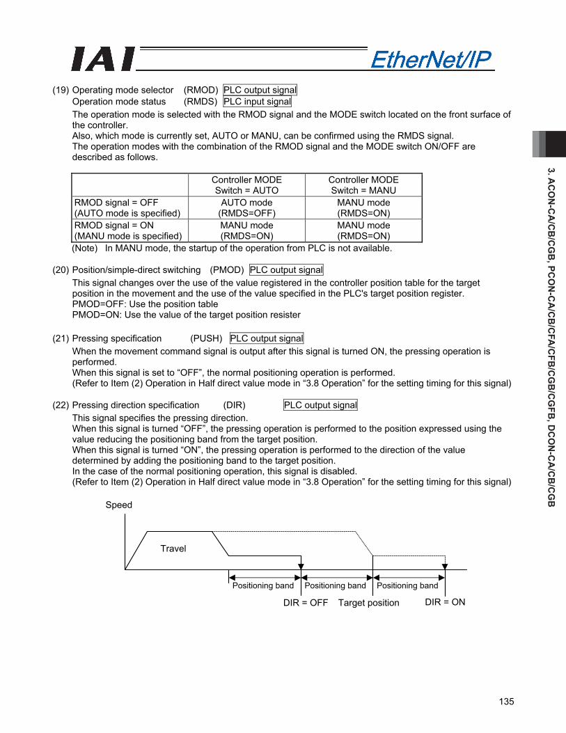
3. AC
ON
-CA
/CB
/CG
B, PC
ON
-CA
/CB
/CFA
/CFB
/CG
B/C
GFB
, DC
ON
-CA
/CB
/CG
B
135
Speed
Travel
Positioning band Positioning band Positioning band
DIR = OFF Target position DIR = ON
(19) Operating mode selector (RMOD) PLC output signal
Operation mode status (RMDS) PLC input signal The operation mode is selected with the RMOD signal and the MODE switch located on the front surface of the controller. Also, which mode is currently set, AUTO or MANU, can be confirmed using the RMDS signal. The operation modes with the combination of the RMOD signal and the MODE switch ON/OFF are described as follows.
Controller MODE Switch = AUTO
Controller MODE Switch = MANU
RMOD signal = OFF (AUTO mode is specified)
AUTO mode (RMDS=OFF)
MANU mode (RMDS=ON)
RMOD signal = ON (MANU mode is specified)
MANU mode (RMDS=ON)
MANU mode (RMDS=ON)
(Note) In MANU mode, the startup of the operation from PLC is not available. (20) Position/simple-direct switching (PMOD) PLC output signal
This signal changes over the use of the value registered in the controller position table for the target position in the movement and the use of the value specified in the PLC's target position register. PMOD=OFF: Use the position table PMOD=ON: Use the value of the target position resister
(21) Pressing specification (PUSH) PLC output signal
When the movement command signal is output after this signal is turned ON, the pressing operation is performed. When this signal is set to “OFF”, the normal positioning operation is performed. (Refer to Item (2) Operation in Half direct value mode in “3.8 Operation” for the setting timing for this signal)
(22) Pressing direction specification (DIR) PLC output signal This signal specifies the pressing direction. When this signal is turned “OFF”, the pressing operation is performed to the position expressed using the value reducing the positioning band from the target position. When this signal is turned “ON”, the pressing operation is performed to the direction of the value determined by adding the positioning band to the target position. In the case of the normal positioning operation, this signal is disabled. (Refer to Item (2) Operation in Half direct value mode in “3.8 Operation” for the setting timing for this signal)
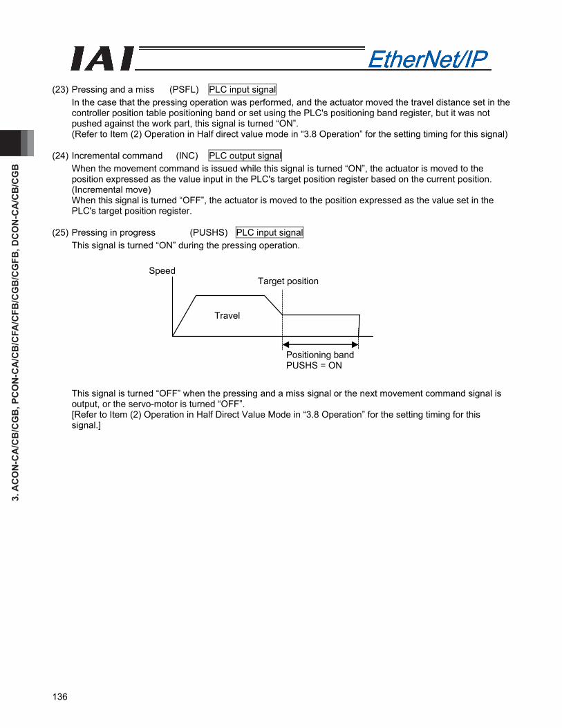
3. A
CO
N-C
A/C
B/C
GB
, PC
ON
-CA
/CB
/CFA
/CFB
/CG
B/C
GFB
, DC
ON
-CA
/CB
/CG
B
136
(23) Pressing and a miss (PSFL) PLC input signal
In the case that the pressing operation was performed, and the actuator moved the travel distance set in the controller position table positioning band or set using the PLC's positioning band register, but it was not pushed against the work part, this signal is turned “ON”. (Refer to Item (2) Operation in Half direct value mode in “3.8 Operation” for the setting timing for this signal)
(24) Incremental command (INC) PLC output signal
When the movement command is issued while this signal is turned “ON”, the actuator is moved to the position expressed as the value input in the PLC's target position register based on the current position. (Incremental move) When this signal is turned “OFF”, the actuator is moved to the position expressed as the value set in the PLC's target position register.
(25) Pressing in progress (PUSHS) PLC input signal
This signal is turned “ON” during the pressing operation.
This signal is turned “OFF” when the pressing and a miss signal or the next movement command signal is output, or the servo-motor is turned “OFF”. [Refer to Item (2) Operation in Half Direct Value Mode in “3.8 Operation” for the setting timing for this signal.]
Speed
Travel
Target position
Positioning band PUSHS = ON

3. AC
ON
-CA
/CB
/CG
B, PC
ON
-CA
/CB
/CFA
/CFB
/CG
B/C
GFB
, DC
ON
-CA
/CB
/CG
B
137
(26) Load output judgment (LOAD) PLC input signal PCON only
This signal is available only in the pressing operation. When this signal is used for pressing-in purpose, it should be known if the set load threshold is reached during the pressing operation. The load threshold and check range are set by the PLC and the LOAD signal will turn ON when the command torque (motor current) exceeds the threshold inside the check range. This signal judges the load output based on the fact that the command torque exceeds the threshold for the specified time period. This processing procedure is the same as for the pressing judgment. The judgment time period can be changed freely using the parameter No. 50 “Load Output Judgment Time Period”. This signal is continued until the next movement command is received.
• Set the pressing speed using the parameter No. 34 “Pressing Speed”. When the machine is delivered, it has been individually set depending on the actuator characteristics. Set an appropriate speed considering the work part material and shape.
• Set the parameter No. 50 “Load Output Judgment Time Period”. • Set the parameter No. 51 “Torque Inspected Range” to “0” (enabled). • Set the threshold inspected width using the PLC's Zone Boundary + Register or Zone Boundary -
Register. • Set the threshold using the PLC's Load Current Threshold Register. • Set the positioning band using the PLC's Positioning Band Register.
Set it a bit longer from the backmost position considering the mechanical dispersion of the work part. Refer to the operation manual for the controller for more information.
Caution: • If the actuator pushes against the work part before the target position, it is regarded as a servo-motor error. Take care of the positional relationship between the target position and the work part position.
• The actuator continues to push the work part with the pressing current at the stop time decided with the current-limiting value. It is not the stop condition, so take the greatest care to deal with it.
Position where this signal is turned ON when the command torque exceeds the threshold within the torque inspected width range
Crack rangeSpeed
Travel
Target position
Position where the actuator is pushed against the work part and the pressing completion is judged so the positioning completion signal is turned “ON”
Positioning band (max. pressing level)
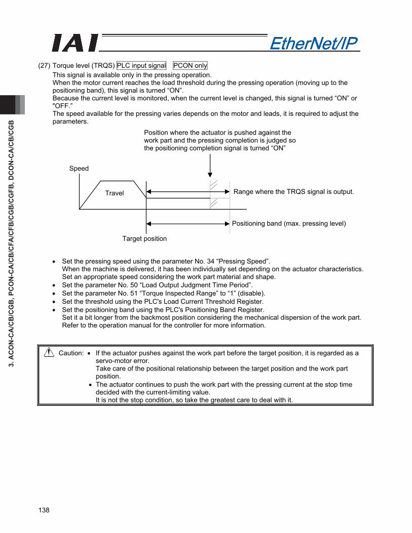
3. A
CO
N-C
A/C
B/C
GB
, PC
ON
-CA
/CB
/CFA
/CFB
/CG
B/C
GFB
, DC
ON
-CA
/CB
/CG
B
138
Target position
Travel
Speed
Position where the actuator is pushed against the work part and the pressing completion is judged so the positioning completion signal is turned “ON”
Range where the TRQS signal is output.
Positioning band (max. pressing level)
(27) Torque level (TRQS) PLC input signal PCON only
This signal is available only in the pressing operation. When the motor current reaches the load threshold during the pressing operation (moving up to the positioning band), this signal is turned “ON”. Because the current level is monitored, when the current level is changed, this signal is turned “ON” or "OFF.” The speed available for the pressing varies depends on the motor and leads, it is required to adjust the parameters.
• Set the pressing speed using the parameter No. 34 “Pressing Speed”. When the machine is delivered, it has been individually set depending on the actuator characteristics. Set an appropriate speed considering the work part material and shape.
• Set the parameter No. 50 “Load Output Judgment Time Period”. • Set the parameter No. 51 “Torque Inspected Range” to “1” (disable). • Set the threshold using the PLC's Load Current Threshold Register. • Set the positioning band using the PLC's Positioning Band Register.
Set it a bit longer from the backmost position considering the mechanical dispersion of the work part. Refer to the operation manual for the controller for more information.
Caution: • If the actuator pushes against the work part before the target position, it is regarded as a servo-motor error. Take care of the positional relationship between the target position and the work part position.
• The actuator continues to push the work part with the pressing current at the stop time decided with the current-limiting value. It is not the stop condition, so take the greatest care to deal with it.
3. AC
ON
-CA
/CB
/CG
B, PC
ON
-CA
/CB
/CFA
/CFB
/CG
B/C
GFB
, DC
ON
-CA
/CB
/CG
B
139
(28) Stopping control mode (SMOD) PLC output signal PCON only
One of the pulse motor general characteristics is that that the holding current in the stop mode is larger than that for the AC servo-motor. Because of this, when the stop time is longer at the standby position, the measure to reduce the power consumption at the stop mode is taken as one of the energy saving measures. SMOD=ON: Full Servo Control System is used in the standby condition. SMOD=OFF: Standby condition
• Full-servo control mode
By means of servo control of the pulse motor, the holding current can be reduced. The reduction level varies depending on the actuator type or load conditions. However, generally, the holding current will be 1/2 to 1/4. The actual holding current can be confirmed in the current monitor window in the PC software. (Note) Under the condition where any external force is given or depending on the stop position, slight
vibration or abnormal noise might be caused.
Before implementing this feature, take care to investigate its effects on the whole system in a controlled manner.
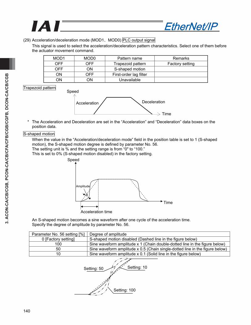
3. A
CO
N-C
A/C
B/C
GB
, PC
ON
-CA
/CB
/CFA
/CFB
/CG
B/C
GFB
, DC
ON
-CA
/CB
/CG
B
140
Setting: 50
Setting: 100
Setting: 10
(29) Acceleration/deceleration mode (MOD1、MOD0) PLC output signal
This signal is used to select the acceleration/deceleration pattern characteristics. Select one of them before the actuator movement command.
MOD1 MOD0 Pattern name Remarks OFF OFF Trapezoid pattern Factory setting OFF ON S-shaped motion ON OFF First-order lag filter ON ON Unavailable
Trapezoid pattern
* The Acceleration and Deceleration are set in the “Acceleration” and “Deceleration” data boxes on the position data.
S-shaped motion When the value in the “Acceleration/deceleration mode” field in the position table is set to 1 (S-shaped motion), the S-shaped motion degree is defined by parameter No. 56. The setting unit is % and the setting range is from “0" to “100.” This is set to 0% (S-shaped motion disabled) in the factory setting.
An S-shaped motion becomes a sine waveform after one cycle of the acceleration time. Specify the degree of amplitude by parameter No. 56.
Parameter No. 56 setting [%] Degree of amplitude
0 [Factory setting] S-shaped motion disabled (Dashed line in the figure below) 100 Sine waveform amplitude x 1 (Chain double-dotted line in the figure below) 50 Sine waveform amplitude x 0.5 (Chain single-dotted line in the figure below)10 Sine waveform amplitude x 0.1 (Solid line in the figure below)
Speed
Acceleration Deceleration
Time
Speed
Time
Acceleration time
Amplitude

3. AC
ON
-CA
/CB
/CG
B, PC
ON
-CA
/CB
/CFA
/CFB
/CG
B/C
GFB
, DC
ON
-CA
/CB
/CG
B
141
Caution: [1] Even if a position command or direct value command with S-shaped motion setting is issued when the actuator is running, S-shaped motion control will not be executed. Issue these commands when the actuator is stopped.
[2] When the index mode is set on the rotary actuator, S-shaped motion is not executed, and, instead, trapezoid control will be executed.
[3] Set the acceleration/deceleration speed so that the time for each will be within two seconds.
[4] An input to pause is not allowed during acceleration or deceleration. It may cause an excessive change in speed.
[5] If a large value is set, the speed will accelerate significantly at around the mid-point of the acceleration/deceleration time. Do not exceed the rated acceleration/deceleration time of the actuator.
First-order lag filter This describes a much gentler acceleration/deceleration curve than that for the linear acceleration/deceleration (trapezoid pattern). Use it when it is not desired to give any slight vibration to the work part in acceleration/deceleration operation.
* The first-order lag degree set using the parameter No. 55 “Position Command Primary Filter Time Constant”. The minimum input unit is 0.1msec and setting range is from “0.0” to “100.0”. When it is set to “0”, the first-order lag filter is disabled. However, the setting is not reflected on the jog operation or inching operation performed using the teaching tools such as PC.
Speed
Time
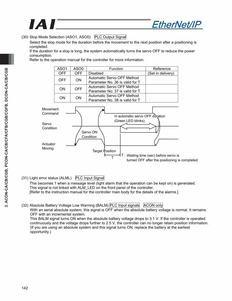
3. A
CO
N-C
A/C
B/C
GB
, PC
ON
-CA
/CB
/CFA
/CFB
/CG
B/C
GFB
, DC
ON
-CA
/CB
/CG
B
142
(30) Stop Mode Selection (ASO1, ASO0) PLC Output Signal
Select the stop mode for the duration before the movement to the next position after a positioning is completed. If the duration for a stop is long, the system automatically turns the servo OFF to reduce the power consumption. Refer to the operation manual for the controller for more information.
ASO1 ASO0 Function Reference OFF OFF Disabled (Set in delivery)
OFF ON Automatic Servo OFF Method Parameter No. 36 is valid for T
ON OFF Automatic Servo OFF Method Parameter No. 37 is valid for T
ON ON Automatic Servo OFF Method Parameter No. 38 is valid for T
T :T
MovementCommand
ActuatorMoving
Target Position
ServoCondition
In automatic servo OFF duration(Green LED blinks)
Servo ONCondition
Waiting time (sec) before servo isturned OFF after the positioning is completed
(31) Light error status (ALML) PLC Input Signal This becomes 1 when a message level (light alarm that the operation can be kept on) is generated. This signal is not linked with ALM_LED on the front panel of the controller. [Refer to the instruction manual for the controller main body for the details of the alarms.]
(32) Absolute Battery Voltage Low Warning (BALM) PLC Input signals ACON only With an serial absolute system, this signal is OFF when the absolute battery voltage is normal. It remains OFF with an incremental system. This BALM signal turns ON when the absolute battery voltage drops to 3.1 V. If the controller is operated continuously and the voltage drops further to 2.5 V, the controller can no longer retain position information. (If you are using an absolute system and this signal turns ON, replace the battery at the earliest opportunity.)
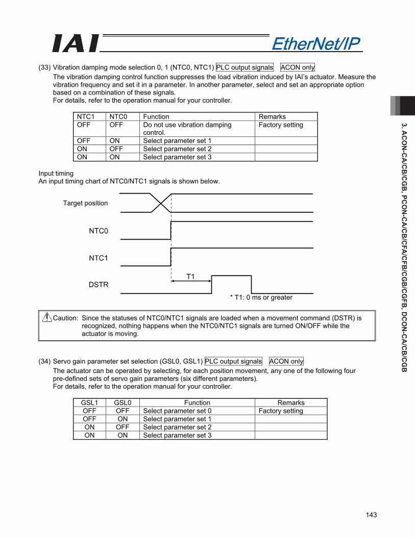
3. AC
ON
-CA
/CB
/CG
B, PC
ON
-CA
/CB
/CFA
/CFB
/CG
B/C
GFB
, DC
ON
-CA
/CB
/CG
B
143
(33) Vibration damping mode selection 0, 1 (NTC0, NTC1) PLC output signals ACON only
The vibration damping control function suppresses the load vibration induced by IAI’s actuator. Measure the vibration frequency and set it in a parameter. In another parameter, select and set an appropriate option based on a combination of these signals. For details, refer to the operation manual for your controller.
NTC1 NTC0 Function Remarks OFF OFF Do not use vibration damping
control. Factory setting
OFF ON Select parameter set 1 ON OFF Select parameter set 2 ON ON Select parameter set 3
Input timing An input timing chart of NTC0/NTC1 signals is shown below.
Caution: Since the statuses of NTC0/NTC1 signals are loaded when a movement command (DSTR) is recognized, nothing happens when the NTC0/NTC1 signals are turned ON/OFF while the actuator is moving.
(34) Servo gain parameter set selection (GSL0, GSL1) PLC output signals ACON only
The actuator can be operated by selecting, for each position movement, any one of the following four pre-defined sets of servo gain parameters (six different parameters). For details, refer to the operation manual for your controller.
GSL1 GSL0 Function Remarks OFF OFF Select parameter set 0 Factory setting OFF ON Select parameter set 1 ON OFF Select parameter set 2 ON ON Select parameter set 3
Target position
* T1: 0 ms or greater
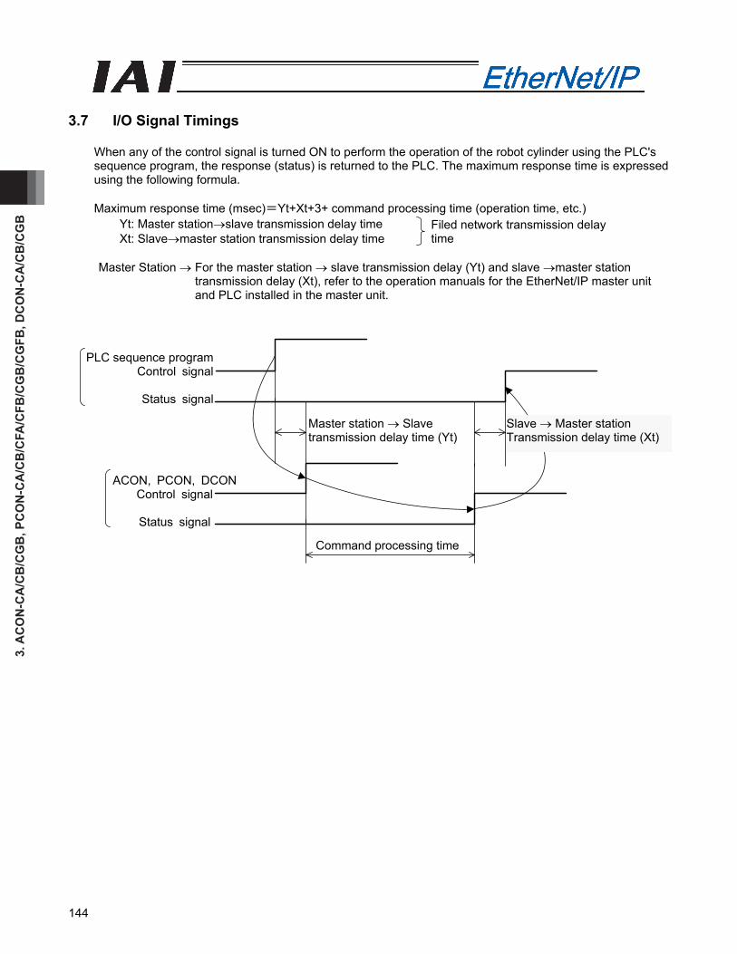
3. A
CO
N-C
A/C
B/C
GB
, PC
ON
-CA
/CB
/CFA
/CFB
/CG
B/C
GFB
, DC
ON
-CA
/CB
/CG
B
144
PLC sequence programControl signal
Status signal
ACON, PCON, DCON Control signal
Status signal
Master station → Slave transmission delay time (Yt)
Slave → Master station Transmission delay time (Xt)
Command processing time
3.7 I/O Signal Timings
When any of the control signal is turned ON to perform the operation of the robot cylinder using the PLC's sequence program, the response (status) is returned to the PLC. The maximum response time is expressed using the following formula.
Maximum response time (msec)=Yt+Xt+3+ command processing time (operation time, etc.)
Yt: Master station→slave transmission delay time Xt: Slave→master station transmission delay time
Master Station → For the master station → slave transmission delay (Yt) and slave →master station
transmission delay (Xt), refer to the operation manuals for the EtherNet/IP master unit and PLC installed in the master unit.
Filed network transmission delay time
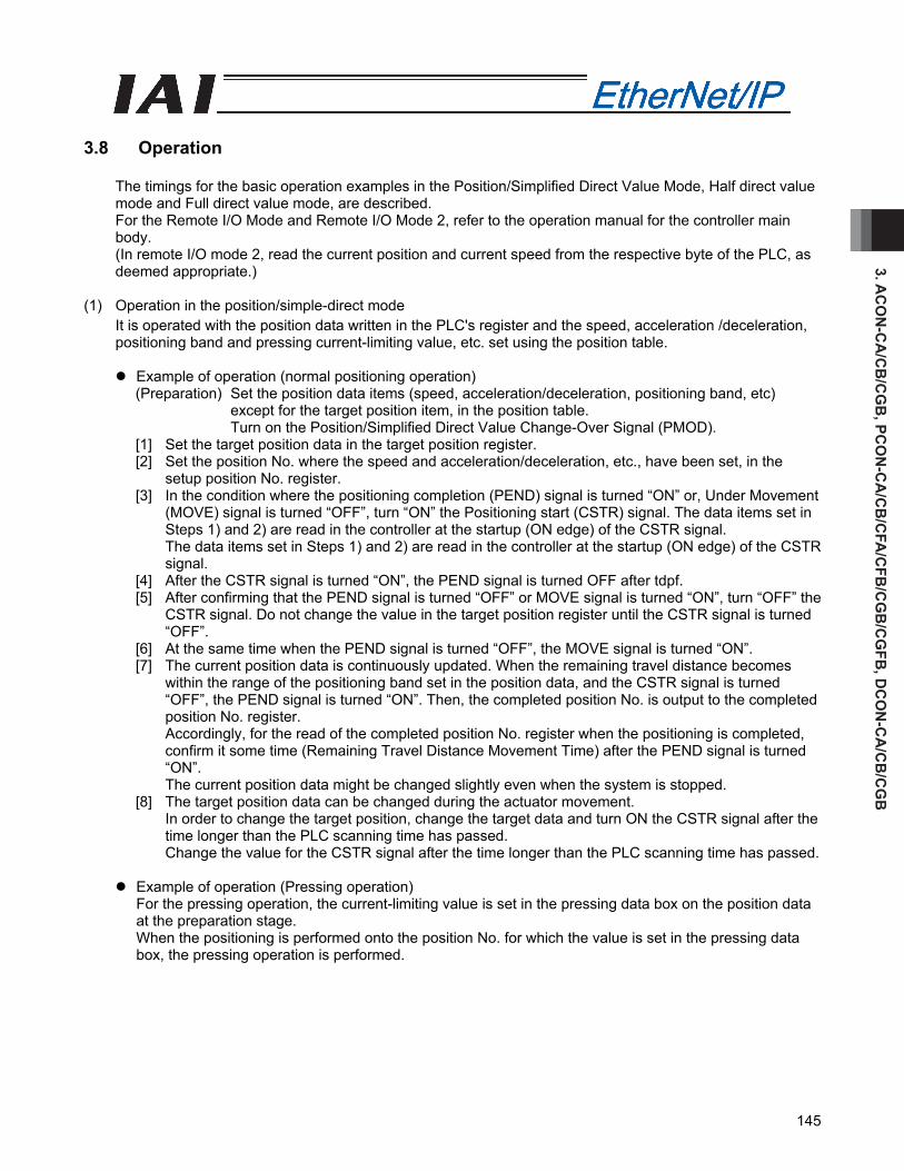
3. AC
ON
-CA
/CB
/CG
B, PC
ON
-CA
/CB
/CFA
/CFB
/CG
B/C
GFB
, DC
ON
-CA
/CB
/CG
B
145
3.8 Operation
The timings for the basic operation examples in the Position/Simplified Direct Value Mode, Half direct value mode and Full direct value mode, are described. For the Remote I/O Mode and Remote I/O Mode 2, refer to the operation manual for the controller main body. (In remote I/O mode 2, read the current position and current speed from the respective byte of the PLC, as deemed appropriate.)
(1) Operation in the position/simple-direct mode
It is operated with the position data written in the PLC's register and the speed, acceleration /deceleration, positioning band and pressing current-limiting value, etc. set using the position table.
Example of operation (normal positioning operation)
(Preparation) Set the position data items (speed, acceleration/deceleration, positioning band, etc) except for the target position item, in the position table. Turn on the Position/Simplified Direct Value Change-Over Signal (PMOD).
[1] Set the target position data in the target position register. [2] Set the position No. where the speed and acceleration/deceleration, etc., have been set, in the
setup position No. register. [3] In the condition where the positioning completion (PEND) signal is turned “ON” or, Under Movement
(MOVE) signal is turned “OFF”, turn “ON” the Positioning start (CSTR) signal. The data items set in Steps 1) and 2) are read in the controller at the startup (ON edge) of the CSTR signal. The data items set in Steps 1) and 2) are read in the controller at the startup (ON edge) of the CSTR signal.
[4] After the CSTR signal is turned “ON”, the PEND signal is turned OFF after tdpf. [5] After confirming that the PEND signal is turned “OFF” or MOVE signal is turned “ON”, turn “OFF” the
CSTR signal. Do not change the value in the target position register until the CSTR signal is turned “OFF”.
[6] At the same time when the PEND signal is turned “OFF”, the MOVE signal is turned “ON”. [7] The current position data is continuously updated. When the remaining travel distance becomes
within the range of the positioning band set in the position data, and the CSTR signal is turned “OFF”, the PEND signal is turned “ON”. Then, the completed position No. is output to the completed position No. register. Accordingly, for the read of the completed position No. register when the positioning is completed, confirm it some time (Remaining Travel Distance Movement Time) after the PEND signal is turned “ON”. The current position data might be changed slightly even when the system is stopped.
[8] The target position data can be changed during the actuator movement. In order to change the target position, change the target data and turn ON the CSTR signal after the time longer than the PLC scanning time has passed. Change the value for the CSTR signal after the time longer than the PLC scanning time has passed.
Example of operation (Pressing operation)
For the pressing operation, the current-limiting value is set in the pressing data box on the position data at the preparation stage. When the positioning is performed onto the position No. for which the value is set in the pressing data box, the pressing operation is performed.
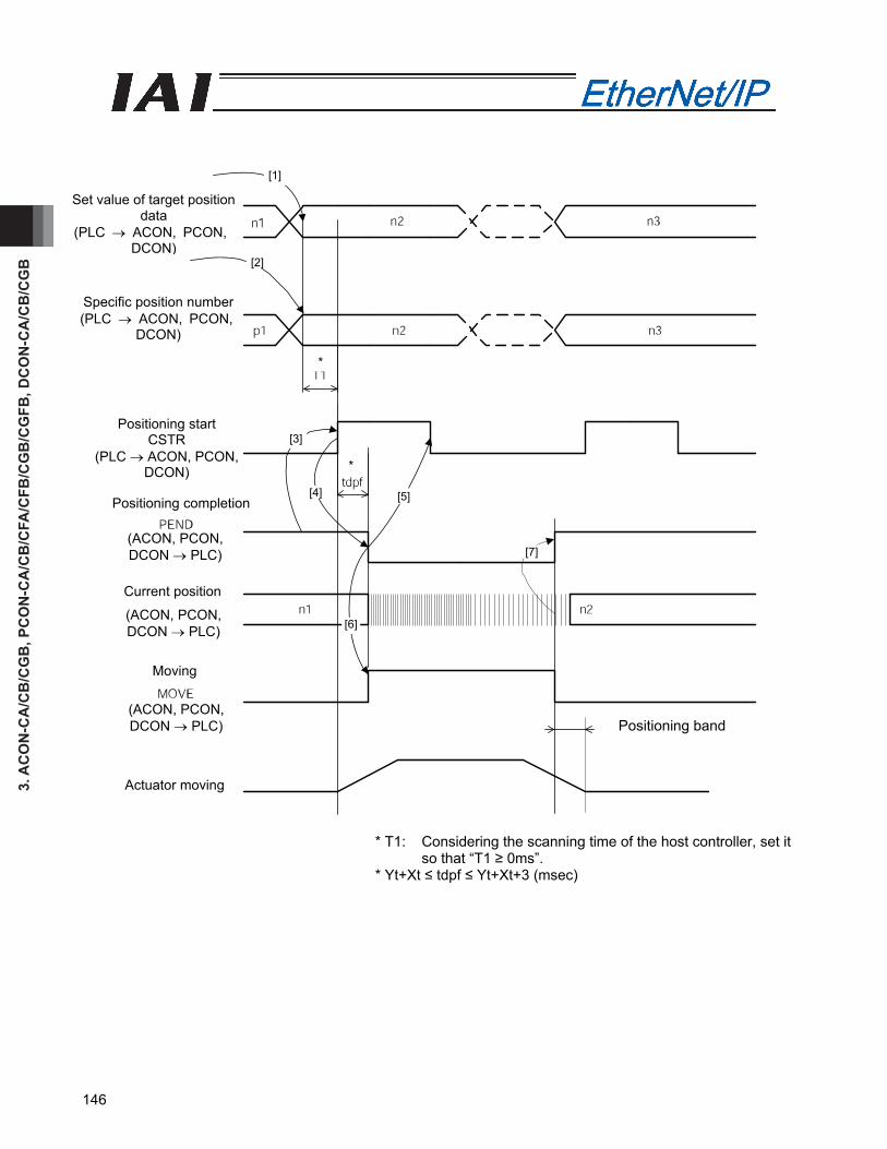
3. A
CO
N-C
A/C
B/C
GB
, PC
ON
-CA
/CB
/CFA
/CFB
/CG
B/C
GFB
, DC
ON
-CA
/CB
/CG
B
146
* T1: Considering the scanning time of the host controller, set it so that “T1 ≥ 0ms”.
* Yt+Xt ≤ tdpf ≤ Yt+Xt+3 (msec)
[7]
[1]
[2]
[3]
[4] [5]
[6]
*
Set value of target position data
(PLC → ACON, PCON, DCON)
Specific position number (PLC → ACON, PCON,
DCON)
Positioning start CSTR
(PLC → ACON, PCON, DCON)
Positioning completion
Current position
Moving
*
Positioning band
Actuator moving
(ACON, PCON, DCON → PLC)
(ACON, PCON, DCON → PLC)
(ACON, PCON, DCON → PLC)
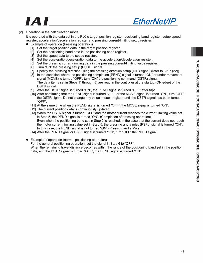
3. AC
ON
-CA
/CB
/CG
B, PC
ON
-CA
/CB
/CFA
/CFB
/CG
B/C
GFB
, DC
ON
-CA
/CB
/CG
B
147
(2) Operation in the half direction mode
It is operated with the data set in the PLC's target position register, positioning band register, setup speed register, acceleration/deceleration register and pressing current-limiting setup register.
Example of operation (Pressing operation) [1] Set the target position data in the target position register. [2] Set the positioning band data in the positioning band register. [3] Set the speed data to the speed resister. [4] Set the acceleration/deceleration data to the acceleration/deceleration resister. [5] Set the pressing current-limiting data in the pressing current-limiting value register. [6] Turn “ON” the pressing setup (PUSH) signal. [7] Specify the pressing direction using the pressing direction setup (DIR) signal. (refer to 3.6.7 (22)) [8] In the condition where the positioning completion (PEND) signal is turned “ON” or under movement
signal (MOVE) is turned “OFF”, turn “ON” the positioning command (DSTR) signal. The data items set in Steps 1) through 5) are read in the controller at the startup (ON edge) of the DSTR signal.
[9] After the DSTR signal is turned “ON”, the PEND signal is turned “OFF” after tdpf. [10] After confirming that the PEND signal is turned “OFF” or the MOVE signal is turned “ON”, turn “OFF”
the DSTR signal. Do not change any value in each register until the DSTR signal has been turned “OFF”.
[11] At the same time when the PEND signal is turned “OFF”, the MOVE signal is turned “ON”. [12] The current position data is continuously updated. [13] When the DSTR signal is turned “OFF” and the motor current reaches the current-limiting value set
in Step 5, the PEND signal is turned “ON”. (Completion of pressing operation) Even when the positioning band set in Step 2 is reached, in the case that the current does not reach the motor current-limiting value set in Step 5, the pressing and a miss (PSFL) signal is turned "ON”. In this case, the PEND signal is not turned “ON” (Pressing and a Miss).
[14] After the PEND signal or PSFL signal is turned “ON”, turn “OFF” the PUSH signal.
Example of operation (normal positioning operation) For the general positioning operation, set the signal in Step 6 to “OFF”. When the remaining travel distance becomes within the range of the positioning band set in the position data, and the DSTR signal is turned “OFF”, the PEND signal is turned “ON”.
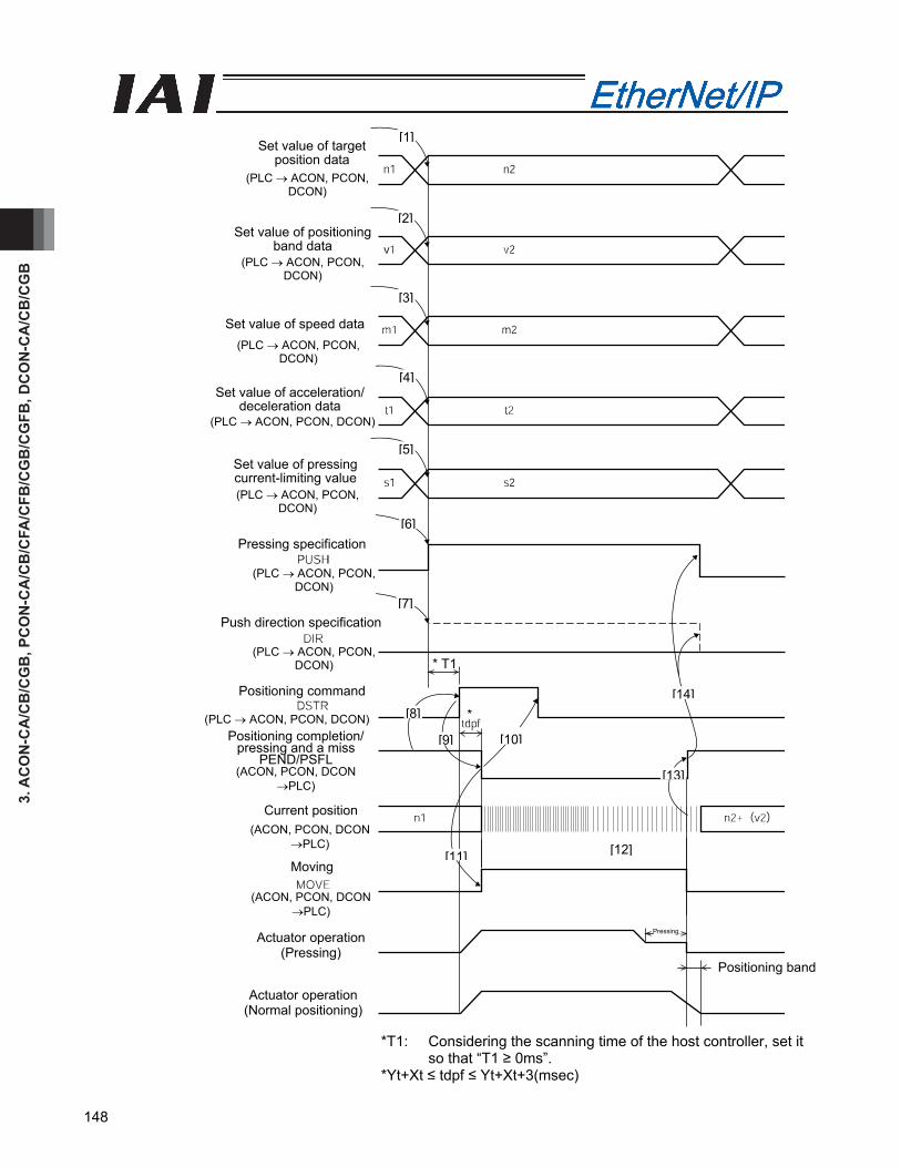
3. A
CO
N-C
A/C
B/C
GB
, PC
ON
-CA
/CB
/CFA
/CFB
/CG
B/C
GFB
, DC
ON
-CA
/CB
/CG
B
148
*T1: Considering the scanning time of the host controller, set it so that “T1 ≥ 0ms”.
*Yt+Xt ≤ tdpf ≤ Yt+Xt+3(msec)
Positioning band
[1]
[2]
[3]
[4]
[5]
[6]
[7]
[8]
[9] [10]
[11] [12]
[14]
[13]
Set value of target position data
Set value of positioning band data
Set value of speed data
*
Set value of acceleration/deceleration data
Set value of pressing current-limiting value
Pressing specification
Push direction specification
Positioning command
Positioning completion/pressing and a miss
PEND/PSFL
Current position
Moving
Actuator operation (Pressing)
Actuator operation (Normal positioning)
* T1
Pressing
(PLC → ACON, PCON, DCON)
(PLC → ACON, PCON, DCON)
(PLC → ACON, PCON, DCON)
(PLC → ACON, PCON, DCON)
(PLC → ACON, PCON, DCON)
(PLC → ACON, PCON,DCON)
(PLC → ACON, PCON,DCON)
(PLC → ACON, PCON, DCON)
(ACON, PCON, DCON →PLC)
(ACON, PCON, DCON →PLC)
(ACON, PCON, DCON →PLC)
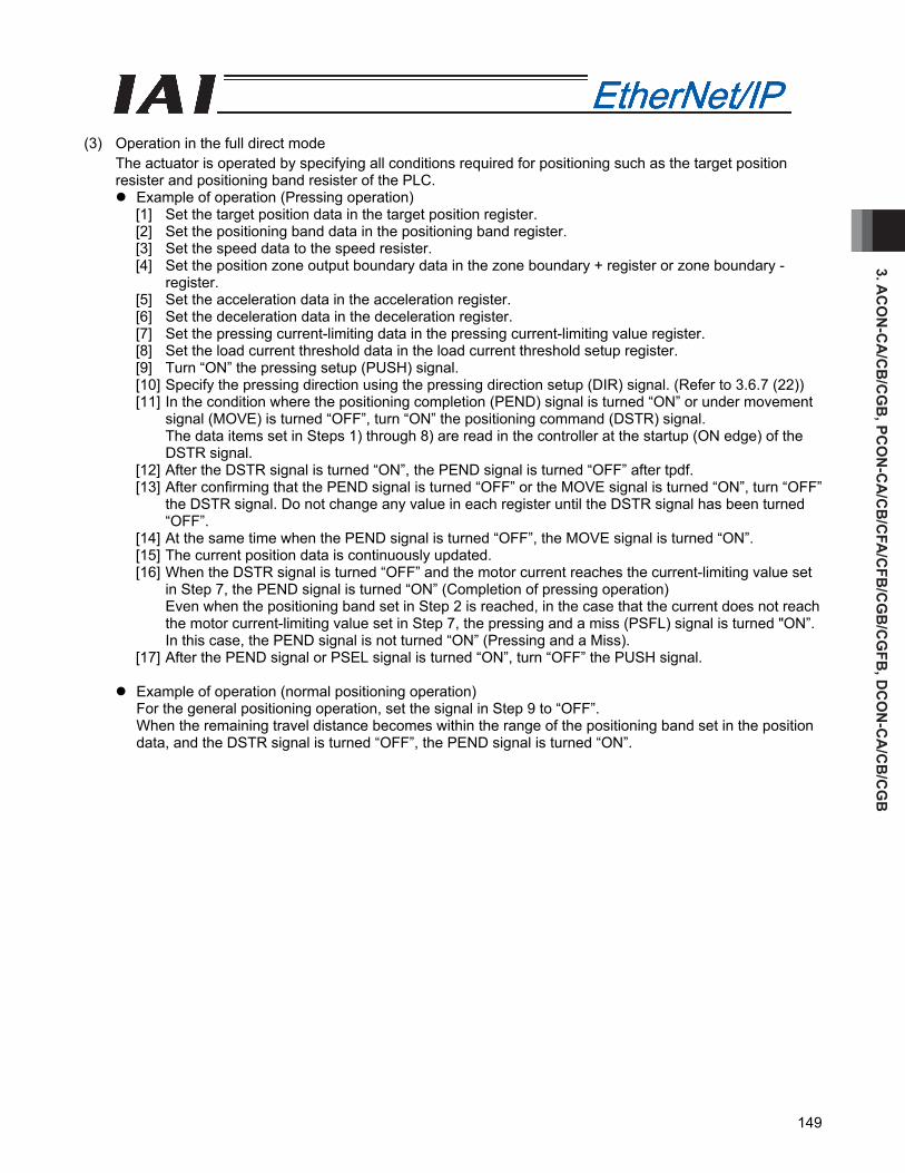
3. AC
ON
-CA
/CB
/CG
B, PC
ON
-CA
/CB
/CFA
/CFB
/CG
B/C
GFB
, DC
ON
-CA
/CB
/CG
B
149
(3) Operation in the full direct mode
The actuator is operated by specifying all conditions required for positioning such as the target position resister and positioning band resister of the PLC.
Example of operation (Pressing operation) [1] Set the target position data in the target position register. [2] Set the positioning band data in the positioning band register. [3] Set the speed data to the speed resister. [4] Set the position zone output boundary data in the zone boundary + register or zone boundary -
register. [5] Set the acceleration data in the acceleration register. [6] Set the deceleration data in the deceleration register. [7] Set the pressing current-limiting data in the pressing current-limiting value register. [8] Set the load current threshold data in the load current threshold setup register. [9] Turn “ON” the pressing setup (PUSH) signal. [10] Specify the pressing direction using the pressing direction setup (DIR) signal. (Refer to 3.6.7 (22)) [11] In the condition where the positioning completion (PEND) signal is turned “ON” or under movement
signal (MOVE) is turned “OFF”, turn “ON” the positioning command (DSTR) signal. The data items set in Steps 1) through 8) are read in the controller at the startup (ON edge) of the DSTR signal.
[12] After the DSTR signal is turned “ON”, the PEND signal is turned “OFF” after tpdf. [13] After confirming that the PEND signal is turned “OFF” or the MOVE signal is turned “ON”, turn “OFF”
the DSTR signal. Do not change any value in each register until the DSTR signal has been turned “OFF”.
[14] At the same time when the PEND signal is turned “OFF”, the MOVE signal is turned “ON”. [15] The current position data is continuously updated. [16] When the DSTR signal is turned “OFF” and the motor current reaches the current-limiting value set
in Step 7, the PEND signal is turned “ON” (Completion of pressing operation) Even when the positioning band set in Step 2 is reached, in the case that the current does not reach the motor current-limiting value set in Step 7, the pressing and a miss (PSFL) signal is turned "ON”. In this case, the PEND signal is not turned “ON” (Pressing and a Miss).
[17] After the PEND signal or PSEL signal is turned “ON”, turn “OFF” the PUSH signal.
Example of operation (normal positioning operation) For the general positioning operation, set the signal in Step 9 to “OFF”. When the remaining travel distance becomes within the range of the positioning band set in the position data, and the DSTR signal is turned “OFF”, the PEND signal is turned “ON”.
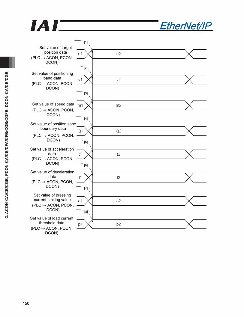
3. A
CO
N-C
A/C
B/C
GB
, PC
ON
-CA
/CB
/CFA
/CFB
/CG
B/C
GFB
, DC
ON
-CA
/CB
/CG
B
150
[1]
[2]
[3]
[4]
[5]
[6]
[7]
[8]
Set value of target position data
Set value of positioning band data
Set value of speed data
Set value of position zone boundary data
Set value of acceleration data
Set value of deceleration data
Set value of pressing current-limiting value
Set value of load current threshold data
(PLC → ACON, PCON, DCON)
(PLC → ACON, PCON, DCON)
(PLC → ACON, PCON, DCON)
(PLC → ACON, PCON, DCON)
(PLC → ACON, PCON, DCON)
(PLC → ACON, PCON, DCON)
(PLC → ACON, PCON, DCON)
(PLC → ACON, PCON, DCON)
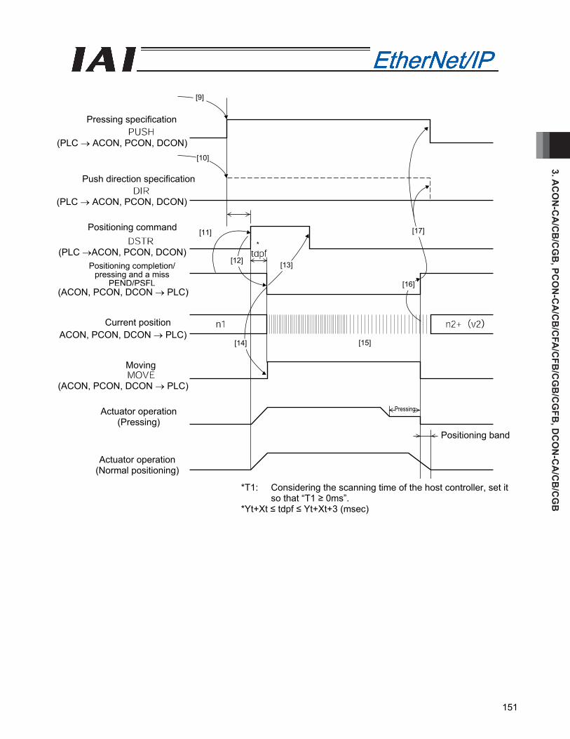
3. AC
ON
-CA
/CB
/CG
B, PC
ON
-CA
/CB
/CFA
/CFB
/CG
B/C
GFB
, DC
ON
-CA
/CB
/CG
B
151
*T1: Considering the scanning time of the host controller, set it so that “T1 ≥ 0ms”.
*Yt+Xt ≤ tdpf ≤ Yt+Xt+3 (msec)
[9]
[10]
[11]
[12] [13]
[17]
[16]
[15][14]
Pressing specification
Push direction specification
Positioning command
Positioning completion/ pressing and a miss
PEND/PSFL
Current position
Moving
Actuator operation (Normal positioning)
Actuator operation (Pressing)
Pressing
*
Positioning band
(ACON, PCON, DCON → PLC)
ACON, PCON, DCON → PLC)
(ACON, PCON, DCON → PLC)
(PLC →ACON, PCON, DCON)
(PLC → ACON, PCON, DCON)
(PLC → ACON, PCON, DCON)
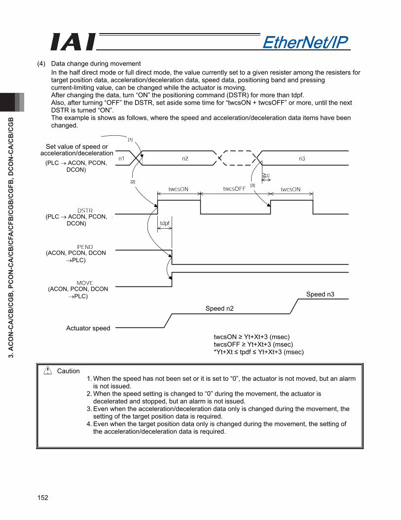
3. A
CO
N-C
A/C
B/C
GB
, PC
ON
-CA
/CB
/CFA
/CFB
/CG
B/C
GFB
, DC
ON
-CA
/CB
/CG
B
152
[1]
[2] [3]
Actuator speed
Speed n2
Speed n3
Set value of speed or acceleration/deceleration
(4) Data change during movement
In the half direct mode or full direct mode, the value currently set to a given resister among the resisters for target position data, acceleration/deceleration data, speed data, positioning band and pressing current-limiting value, can be changed while the actuator is moving. After changing the data, turn “ON” the positioning command (DSTR) for more than tdpf. Also, after turning “OFF” the DSTR, set aside some time for “twcsON + twcsOFF” or more, until the next DSTR is turned “ON”. The example is shows as follows, where the speed and acceleration/deceleration data items have been changed.
twcsON ≥ Yt+Xt+3 (msec) twcsOFF ≥ Yt+Xt+3 (msec) *Yt+Xt ≤ tpdf ≤ Yt+Xt+3 (msec)
Caution 1. When the speed has not been set or it is set to “0”, the actuator is not moved, but an alarm
is not issued. 2. When the speed setting is changed to “0” during the movement, the actuator is
decelerated and stopped, but an alarm is not issued. 3. Even when the acceleration/deceleration data only is changed during the movement, the
setting of the target position data is required. 4. Even when the target position data only is changed during the movement, the setting of
the acceleration/deceleration data is required.
(PLC → ACON, PCON, DCON)
(PLC → ACON, PCON, DCON)
(ACON, PCON, DCON →PLC)
(ACON, PCON, DCON →PLC)
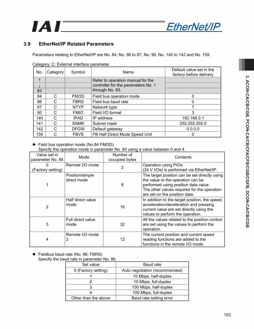
3. AC
ON
-CA
/CB
/CG
B, PC
ON
-CA
/CB
/CFA
/CFB
/CG
B/C
GFB
, DC
ON
-CA
/CB
/CG
B
153
3.9 EtherNet/IP Related Parameters
Parameters relating to EtherNet/IP are No. 84, No. 86 to 87, No. 90, No. 140 to 142 and No. 159.
Category: C: External interface parameter
No. Category Symbol Name Default value set in the factory before delivery
1
~ 83
Refer to operation manual for the controller for the parameters No. 1 through No. 83.
84 C FMOD Field bus operation mode 0 86 C FBRS Field bus baud rate 0 87 C NTYP Network type 7 90 C FMIO Field I/O format 3 140 C IPAD IP address 192.168.0.1 141 C SNMK Subnet mask 255.255.255.0 142 C DFGW Default gateway 0.0.0.0 159 C FBVS FB Half Direct Mode Speed Unit 0
Field bus operation mode (No.84 FMOD)
Specify the operation mode in parameter No. 84 using a value between 0 and 4. Value set in
parameter No. 84 Mode Number of occupied bytes Contents
0 (Factory setting)
Remote I/O mode 2 Operation using PIOs (24 V I/Os) is performed via EtherNet/IP.
1
Position/simple direct mode
8
The target position can be set directly using the value or the operation can be performed using position data value. The other values required for the operation are set on the position data.
2
Half direct value mode 16
In addition to the target position, the speed, acceleration/deceleration and pressing current value are set directly using the values to perform the operation.
3 Full direct value mode 32
All the values related to the position control are set using the values to perform the operation.
4 Remote I/O mode 2 12
The current position and current speed reading functions are added to the functions in the remote I/O mode.
Fieldbus baud rate (No. 86: FBRS)
Specify the baud rate in parameter No. 86. Set value Baud rate
0 (Factory setting) Auto negotiation (recommended) 1 10 Mbps, half-duplex 2 10 Mbps, full-duplex 3 100 Mbps, half-duplex 4 100 Mbps, full-duplex
Other than the above Baud rate setting error

3. A
CO
N-C
A/C
B/C
GB
, PC
ON
-CA
/CB
/CFA
/CFB
/CG
B/C
GFB
, DC
ON
-CA
/CB
/CG
B
154
Network type (No.87 NTYP)
The network module type is set for the parameter No. 87. Do not change the default value.
Field I/O format (No.90 FMIO) Addresses in the PLC are assigned in units of 16 points (2 bytes) based on the node address set in the controller and the occupied bytes in each operation mode. By changing the setting of parameter No. 90, data elements can be swapped within a boundary of two words or less in units of bytes during communication using the I/O areas of the PLC.
Value set in
parameter No. 90 Contents
0 Data exchange is not performed. The data is sent directly to the PLC. (Refer to “Example i”.)
1 The host bytes are exchanged with slave bytes in the host words and slave words. (Refer to “Example ii”.)
2 In the case of word register, the host words are exchanged with the slave words. (Refer to “Example iii”.)
3 (Factory setting) The host bytes are exchanged with slave bytes in the host words and slave words. In addition, the upper word and lower word are swapped for word resisters. (Refer to “Example iv”.)
(Example i) Set value = “0” indicates ON, while indicates OFF
PCON Input resister
Hexadecimal data
Hexadecimal data
PLC: Output CH
PCON Output resister
Hexadecimal data
Hexadecimal data
PLC: Input CH

3. AC
ON
-CA
/CB
/CG
B, PC
ON
-CA
/CB
/CFA
/CFB
/CG
B/C
GFB
, DC
ON
-CA
/CB
/CG
B
155
(Example ii) Set value = “1” indicates ON, while indicates OFF
PCON Input resister
PCON Output resister
Hexadecimal data
Hexadecimal data
Hexadecimal data
Hexadecimal data
PLC: Output CH
PLC: Input CH
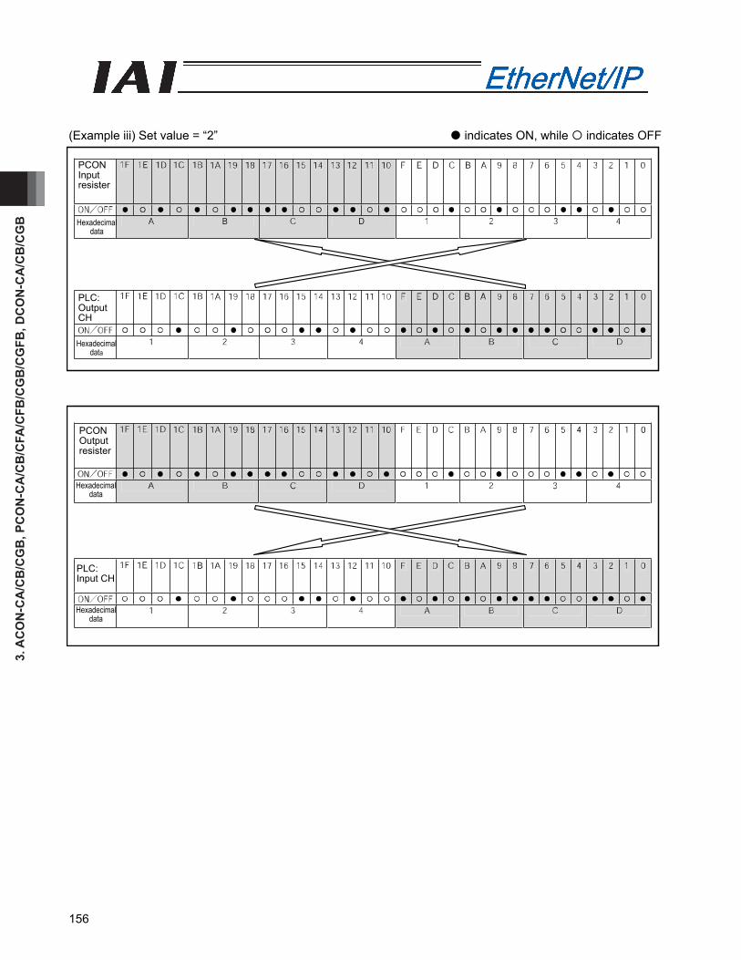
3. A
CO
N-C
A/C
B/C
GB
, PC
ON
-CA
/CB
/CFA
/CFB
/CG
B/C
GFB
, DC
ON
-CA
/CB
/CG
B
156
(Example iii) Set value = “2” indicates ON, while indicates OFF
PCON Input resister
PCON Output resister
Hexadecimal data
Hexadecimal data
Hexadecimal data
Hexadecimal data
PLC: Output CH
PLC: Input CH

3. AC
ON
-CA
/CB
/CG
B, PC
ON
-CA
/CB
/CFA
/CFB
/CG
B/C
GFB
, DC
ON
-CA
/CB
/CG
B
157
(Example iv) Set value = “3” indicates ON, while indicates OFF
PCON Input resister
PCON Output resister
Hexadecimal data
Hexadecimal data
Hexadecimal data
Hexadecimal data
PLC: Output CH
PLC: Input CH

3. A
CO
N-C
A/C
B/C
GB
, PC
ON
-CA
/CB
/CFA
/CFB
/CG
B/C
GFB
, DC
ON
-CA
/CB
/CG
B
158
IP address (No. 140: IPAD)
Specify the IP address in parameter No. 140.
Setting range: 0.0.0.0 to 255.255.255.255 (Factory setting: 192.168.0.1) (Note) When this parameter is set to 0.0.0.0, DHCP is enabled. Manual setting is recommended.
Subnet mask (No. 141: SNMK)
Specify the subnet mask in parameter No. 141.
Settable range: 0.0.0.0 to 255.255.255.255 (Factory setting: 255.255.255.0)
Default gateway (No. 142: DFGW) Specify the default gateway in parameter No. 142.
Settable range: 0.0.0.0 to 255.255.255.255 (Factory setting: 0.0.0.0)
FB Half Direct Mode Speed Unit (No.159 FBVS)
Determines the unit of measure when operating the unit in Half Direct Mode. Parameter No. 159 Setting Value Speed Setting Unit
0 (Set in delivery) 1mm/sec 1 0.1mm/sec
3.10 Troubleshooting
Alarm messages and causes/actions When an alarm occurs, a corresponding simple alarm code is indicated by the completed position number bits (four bits of PM1 to PM8) in remote I/O mode 1, 2 or 3. In position/simple direct mode 1 or 2, this simple alarm code is output to the (n+4, n+5) bytes. In half direct mode 1, 2 or 3 or in the full direct mode, this alarm code is output to the (n+12, n+13) bytes [1] Check the alarm code using the monitor function of the PLC, etc., or connect the RC PC software or
other teaching tool and check the status monitor screen. [2] Search the alarm list in the operation manual for your controller to find the section corresponding to
the identified alarm code. [3] Take an appropriate action according to the explanation of the alarm code.
For the alarm codes listed below, take the corresponding actions:
Code Error name ID (*1)
RES(*2) Cause/action
0F2 Fieldbus module error 05 x Cause: A fieldbus module error has been
detected. Action: Check the applicable parameters.
0F3 Fieldbus module non-detection error 04 x
Cause: The module could not be detected. Action: Reconnect the power. If the problem
persists, please contact IAI. (*1) ID → Simple alarm code (*2) RES → Alarm can/cannot be reset – O: Alarm can be reset / X: Alarm cannot be reset
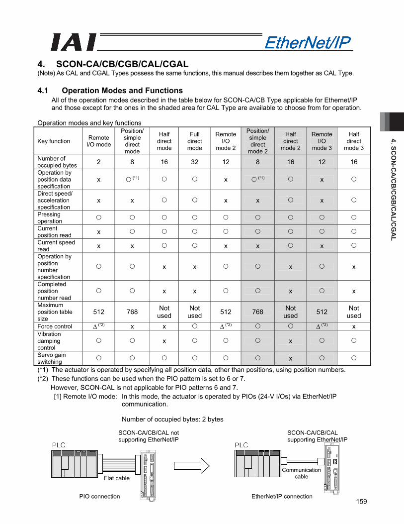
4. SCO
N-C
A/C
B/C
GB
/CA
L/CG
AL
159
4. SCON-CA/CB/CGB/CAL/CGAL (Note) As CAL and CGAL Types possess the same functions, this manual describes them together as CAL Type. 4.1 Operation Modes and Functions
All of the operation modes described in the table below for SCON-CA/CB Type applicable for Ethernet/IP and those except for the ones in the shaded area for CAL Type are available to choose from for operation.
Operation modes and key functions
Key function Remote I/O mode
Position/ simple direct mode
Half direct mode
Full direct mode
Remote I/O
mode 2
Position/simple direct
mode 2
Half direct
mode 2
Remote I/O
mode 3
Half direct
mode 3
Number of occupied bytes 2 8 16 32 12 8 16 12 16 Operation by position data specification
x (*1) x (*1) x
Direct speed/ acceleration specification
x x x x x
Pressing operation Current position read x Current speed read x x x x x Operation by position number specification
x x x x
Completed position number read
x x x x
Maximum position table size
512 768 Not used
Not used 512 768 Not
used 512 Not used
Force control ∆ (*2) x x ∆ (*2) ∆ (*2) x Vibration damping control
x x
Servo gain switching x
(*1) The actuator is operated by specifying all position data, other than positions, using position numbers. (*2) These functions can be used when the PIO pattern is set to 6 or 7.
However, SCON-CAL is not applicable for PIO patterns 6 and 7. [1] Remote I/O mode: In this mode, the actuator is operated by PIOs (24-V I/Os) via EtherNet/IP
communication.
Number of occupied bytes: 2 bytes
EtherNet/IP connection
Flat cable
SCON-CA/CB/CAL not supporting EtherNet/IP
PIO connection
SCON-CA/CB/CAL supporting EtherNet/IP
Communication cable
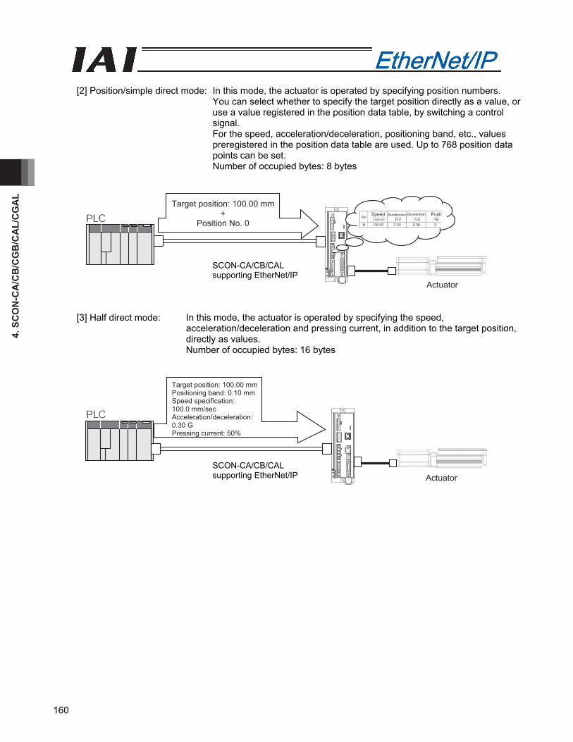
4. S
CO
N-C
A/C
B/C
GB
/CA
L/C
GA
L
160
[2] Position/simple direct mode: In this mode, the actuator is operated by specifying position numbers.
You can select whether to specify the target position directly as a value, or use a value registered in the position data table, by switching a control signal. For the speed, acceleration/deceleration, positioning band, etc., values preregistered in the position data table are used. Up to 768 position data points can be set. Number of occupied bytes: 8 bytes
Target position: 100.00 mm+
Position No. 0
SCON-CA supporting EtherNet/IP
Actuator
Speed Acceleration Push Deceleration
[3] Half direct mode: In this mode, the actuator is operated by specifying the speed, acceleration/deceleration and pressing current, in addition to the target position, directly as values. Number of occupied bytes: 16 bytes
SCON-CA supporting EtherNet/IP Actuator
Target position: 100.00 mm Positioning band: 0.10 mm Speed specification: 100.0 mm/sec Acceleration/deceleration: 0.30 G Pressing current: 50%
SCON-CA/CB/CAL supporting EtherNet/IP
SCON-CA/CB/CAL supporting EtherNet/IP
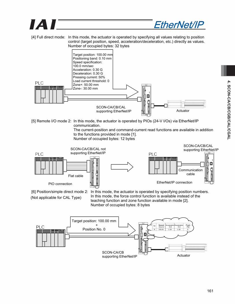
4. SCO
N-C
A/C
B/C
GB
/CA
L/CG
AL
161
[4] Full direct mode: In this mode, the actuator is operated by specifying all values relating to position
control (target position, speed, acceleration/deceleration, etc.) directly as values. Number of occupied bytes: 32 bytes
[5] Remote I/O mode 2: In this mode, the actuator is operated by PIOs (24-V I/Os) via EtherNet/IP communication. The current-position and command-current read functions are available in addition to the functions provided in mode [1]. Number of occupied bytes: 12 bytes
[6] Position/simple direct mode 2: In this mode, the actuator is operated by specifying position numbers.
In this mode, the force control function is available instead of the teaching function and zone function available in mode [2]. Number of occupied bytes: 8 bytes
PIO connection
SCON-CA/CB/CAL not supporting EtherNet/IP
SCON-CA/CB/CAL supporting EtherNet/IP
EtherNet/IP connection
Communication cableFlat cable
SCON-CA/CB supporting EtherNet/IP Actuator
Target position: 100.00 mm+
Position No. 0 Speed Acceleration Deceleration Push
Target position: 100.00 mmPositioning band: 0.10 mmSpeed specification: 100.0 mm/sec Acceleration: 0.30 G Deceleration: 0.30 G Pressing current: 50% Load current threshold: 0 Zone+: 50.00 mm Zone-: 30.00 mm
SCON-CA/CB/CAL supporting EtherNet/IP Actuator
(Not applicable for CAL Type)
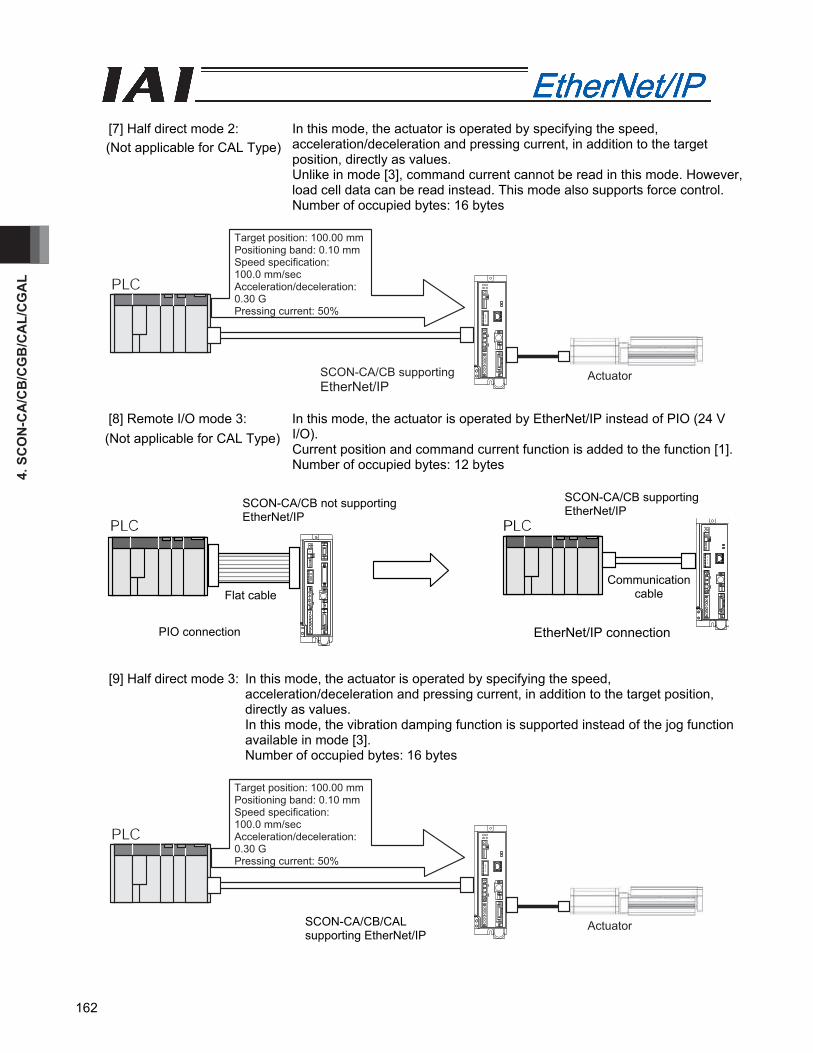
4. S
CO
N-C
A/C
B/C
GB
/CA
L/C
GA
L
162
[7] Half direct mode 2: In this mode, the actuator is operated by specifying the speed,
acceleration/deceleration and pressing current, in addition to the target position, directly as values. Unlike in mode [3], command current cannot be read in this mode. However, load cell data can be read instead. This mode also supports force control. Number of occupied bytes: 16 bytes
SCON-CA/CB supporting EtherNet/IP
Actuator
Target position: 100.00 mmPositioning band: 0.10 mmSpeed specification: 100.0 mm/sec Acceleration/deceleration:0.30 G Pressing current: 50%
[8] Remote I/O mode 3: In this mode, the actuator is operated by EtherNet/IP instead of PIO (24 V I/O). Current position and command current function is added to the function [1]. Number of occupied bytes: 12 bytes
[9] Half direct mode 3: In this mode, the actuator is operated by specifying the speed, acceleration/deceleration and pressing current, in addition to the target position, directly as values. In this mode, the vibration damping function is supported instead of the jog function available in mode [3]. Number of occupied bytes: 16 bytes
SCON-CA supporting EtherNet/IP
Actuator
Target position: 100.00 mmPositioning band: 0.10 mmSpeed specification: 100.0 mm/sec Acceleration/deceleration:0.30 G Pressing current: 50%
SCON-CA/CB not supporting EtherNet/IP
PIO connection
SCON-CA/CB supporting EtherNet/IP
EtherNet/IP connection
Flat cable Communication
cable
(Not applicable for CAL Type)
(Not applicable for CAL Type)
SCON-CA/CB/CAL supporting EtherNet/IP
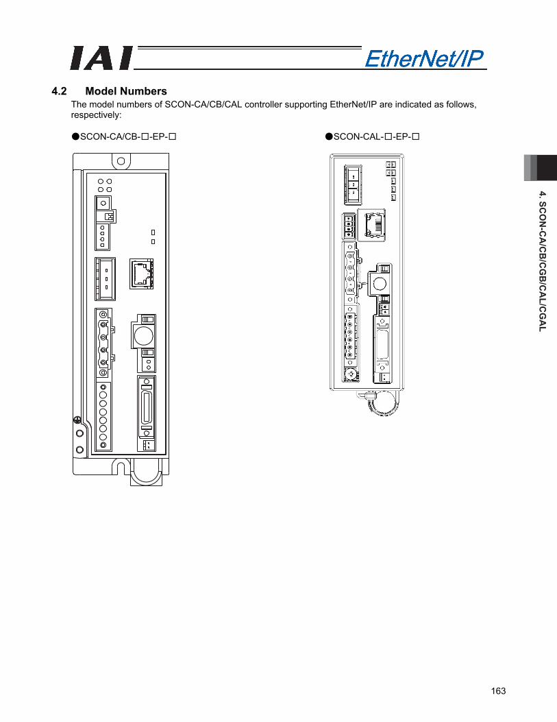
4. SCO
N-C
A/C
B/C
GB
/CA
L/CG
AL
163
4.2 Model Numbers
The model numbers of SCON-CA/CB/CAL controller supporting EtherNet/IP are indicated as follows, respectively:
●SCON-CA/CB-□-EP-□ ●SCON-CAL-□-EP-□
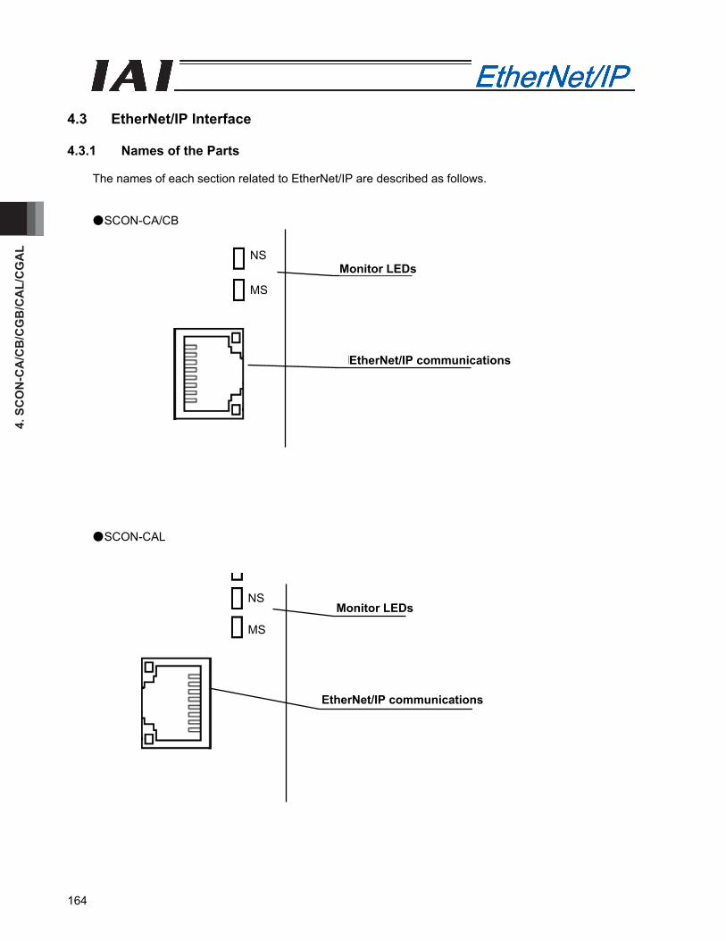
4. S
CO
N-C
A/C
B/C
GB
/CA
L/C
GA
L
164
Monitor LEDs
EtherNet/IP communications
Monitor LEDs
EtherNet/IP communications
4.3 EtherNet/IP Interface 4.3.1 Names of the Parts
The names of each section related to EtherNet/IP are described as follows.
●SCON-CA/CB
●SCON-CAL
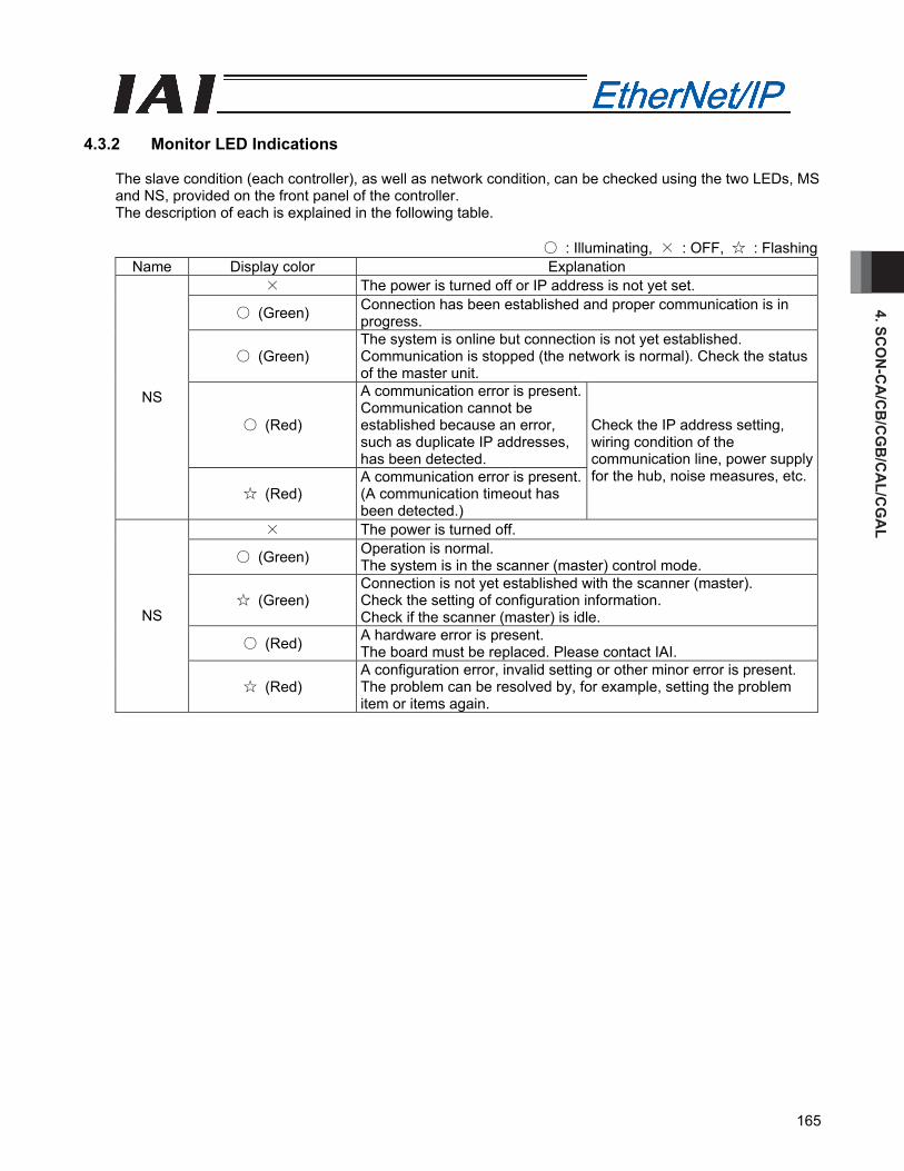
4. SCO
N-C
A/C
B/C
GB
/CA
L/CG
AL
165
4.3.2 Monitor LED Indications
The slave condition (each controller), as well as network condition, can be checked using the two LEDs, MS and NS, provided on the front panel of the controller. The description of each is explained in the following table.
○ : Illuminating, × : OFF, ☆ : Flashing
Name Display color Explanation × The power is turned off or IP address is not yet set.
○ (Green) Connection has been established and proper communication is in progress.
○ (Green) The system is online but connection is not yet established. Communication is stopped (the network is normal). Check the status of the master unit.
○ (Red)
A communication error is present. Communication cannot be established because an error, such as duplicate IP addresses, has been detected.
NS
☆ (Red) A communication error is present. (A communication timeout has been detected.)
Check the IP address setting, wiring condition of the communication line, power supply for the hub, noise measures, etc.
× The power is turned off.
○ (Green) Operation is normal. The system is in the scanner (master) control mode.
☆ (Green) Connection is not yet established with the scanner (master). Check the setting of configuration information. Check if the scanner (master) is idle.
○ (Red) A hardware error is present. The board must be replaced. Please contact IAI.
NS
☆ (Red) A configuration error, invalid setting or other minor error is present. The problem can be resolved by, for example, setting the problem item or items again.
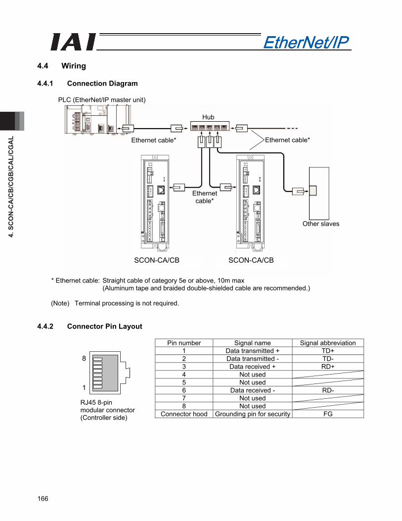
4. S
CO
N-C
A/C
B/C
GB
/CA
L/C
GA
L
166
4.4 Wiring 4.4.1 Connection Diagram
* Ethernet cable: Straight cable of category 5e or above, 10m max (Aluminum tape and braided double-shielded cable are recommended.)
(Note) Terminal processing is not required.
4.4.2 Connector Pin Layout
Pin number Signal name Signal abbreviation 1 Data transmitted + TD+ 2 Data transmitted - TD- 3 Data received + RD+ 4 Not used 5 Not used 6 Data received - RD- 7 Not used 8 Not used
Connector hood Grounding pin for security FG
SCON-CA SCON-CA
RJ45 8-pin modular connector (Controller side)
PLC (EtherNet/IP master unit)
Ethernet cable*
Ethernet cable* Ethernet cable*
Other slaves
Hub
8
1
SCON-CA/CB SCON-CA/CB
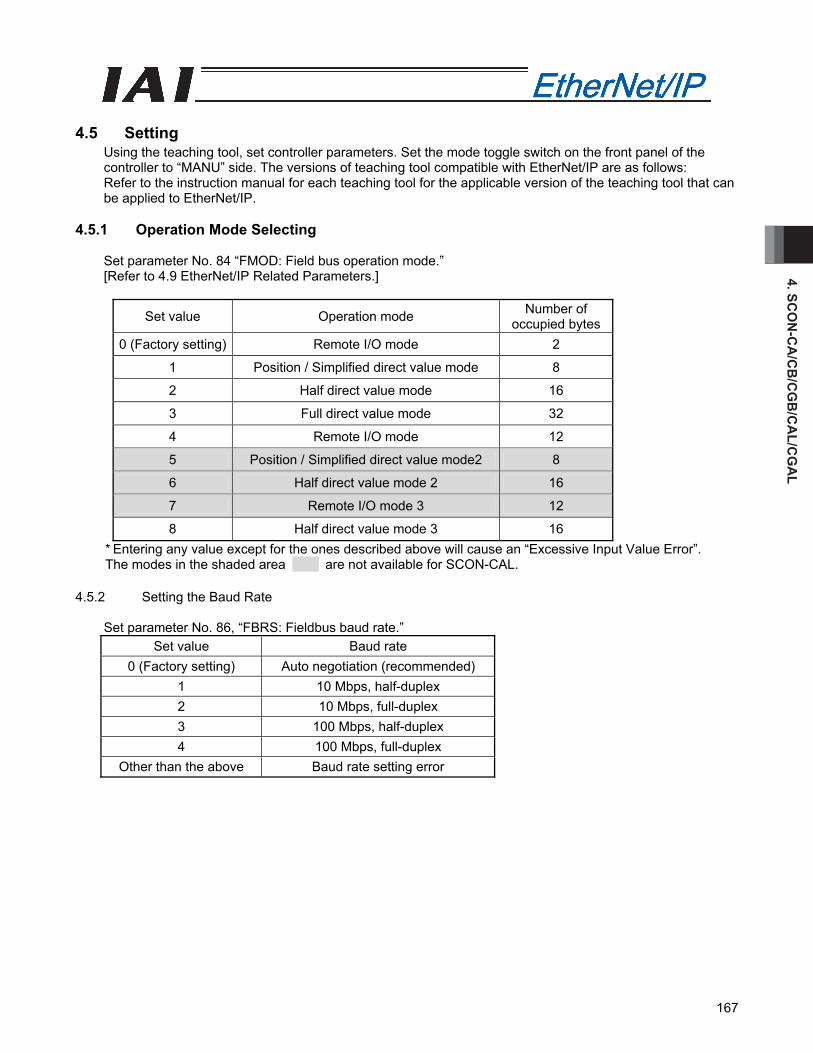
4. SCO
N-C
A/C
B/C
GB
/CA
L/CG
AL
167
4.5 Setting
Using the teaching tool, set controller parameters. Set the mode toggle switch on the front panel of the controller to “MANU” side. The versions of teaching tool compatible with EtherNet/IP are as follows: Refer to the instruction manual for each teaching tool for the applicable version of the teaching tool that can be applied to EtherNet/IP.
4.5.1 Operation Mode Selecting
Set parameter No. 84 “FMOD: Field bus operation mode.” [Refer to 4.9 EtherNet/IP Related Parameters.]
Set value Operation mode Number of occupied bytes
0 (Factory setting) Remote I/O mode 2
1 Position / Simplified direct value mode 8
2 Half direct value mode 16
3 Full direct value mode 32
4 Remote I/O mode 12
5 Position / Simplified direct value mode2 8
6 Half direct value mode 2 16
7 Remote I/O mode 3 12
8 Half direct value mode 3 16 * Entering any value except for the ones described above will cause an “Excessive Input Value Error”. The modes in the shaded area are not available for SCON-CAL.
4.5.2 Setting the Baud Rate
Set parameter No. 86, “FBRS: Fieldbus baud rate.” Set value Baud rate
0 (Factory setting) Auto negotiation (recommended) 1 10 Mbps, half-duplex 2 10 Mbps, full-duplex 3 100 Mbps, half-duplex 4 100 Mbps, full-duplex
Other than the above Baud rate setting error
4. S
CO
N-C
A/C
B/C
GB
/CA
L/C
GA
L
168
4.5.3 Setting the IP Address
Set parameter No. 140, “IPAD: IP address.” [Refer to 4.9, “EtherNet/IP Parameters.”] Settable Range:0.0.0.0 to 255.255.255.255 (It is set to “192.168.0.1” when the machine is delivered from the factory.) (Note 1) Exercise caution to avoid IP address duplication.
For details, refer to the operation manuals of the master unit and PLC in which in the master unit is installed.
4.5.4 Setting the Subnet Mask
Set parameter No. 141, “SNMK: Subnet mask.” Set the same value you have set in the master unit and other slaves (on the same network). [Refer to 4.9, “EtherNet/IP Parameters.”] Settable range: 0.0.0.0 to 255.255.255.255 (The factory setting is 255.255.255.0.)
4.5.5 Setting the Default Gateway
If necessary, set parameter No. 142, “DFGW: Default gateway.” [Refer to 4.9, “EtherNet/IP Parameters.”] Settable range: 0.0.0.0 to 255.255.255.255 (The factory setting is 192.168.0.0.)
(Note) After the parameter setting, turn on the power to the controller again and return the mode toggle switch
on the front of the controller to “AUTO” side. When the switch is set to “MANU”, the operation using PLC is not available.
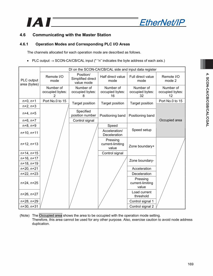
4. SCO
N-C
A/C
B/C
GB
/CA
L/CG
AL
169
4.6 Communicating with the Master Station 4.6.1 Operation Modes and Corresponding PLC I/O Areas
The channels allocated for each operation mode are described as follows. • PLC output → SCON-CA/CB/CAL input (* “n” indicates the byte address of each axis.)
DI on the SCON-CA/CB/CAL side and input data register
Remote I/O mode
Position/ Simplified direct
value mode
Half direct value mode
Full direct value mode
Remote I/O mode 2 PLC output
area (bytes) Number of
occupied bytes: 2
Number of occupied bytes:
8
Number of occupied bytes:
16
Number of occupied bytes:
32
Number of occupied bytes:
12 n+0, n+1 Port No.0 to 15 Port No.0 to 15n+2, n+3
Target position Target position Target position
n+4, n+5 Specified position number
n+6, n+7 Control signal Positioning band Positioning band
n+8, n+9 Speed
n+10, n+11 Acceleration/ Deceleration
Speed setup
Occupied area
n+12, n+13 Pressing
current-limiting value
n+14, n+15 Control signal
Zone boundary+
n+16, n+17 n+18, n+19
Zone boundary-
n+20, n+21 Acceleration n+22, n+23 Deceleration
n+24, n+25 Pressing
current-limiting value
n+26, n+27 Load current threshold
n+28, n+29 Control signal 1 n+30, n+31
Control signal 2
(Note) The Occupied area shows the area to be occupied with the operation mode setting.
Therefore, this area cannot be used for any other purpose. Also, exercise caution to avoid node address duplication.
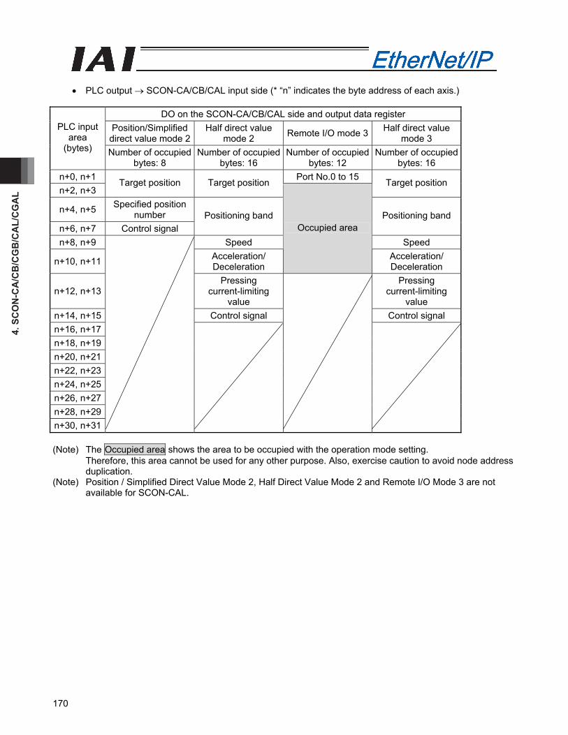
4. S
CO
N-C
A/C
B/C
GB
/CA
L/C
GA
L
170
• PLC output → SCON-CA/CB/CAL input side (* “n” indicates the byte address of each axis.)
DO on the SCON-CA/CB/CAL side and output data register
Position/Simplified direct value mode 2
Half direct value mode 2 Remote I/O mode 3 Half direct value
mode 3 PLC input
area (bytes) Number of occupied
bytes: 8 Number of occupied
bytes: 16 Number of occupied
bytes: 12 Number of occupied
bytes: 16 n+0, n+1 Port No.0 to 15 n+2, n+3
Target position Target position Target position
n+4, n+5 Specified position number
n+6, n+7 Control signal Positioning band Positioning band
n+8, n+9 Speed Speed
n+10, n+11 Acceleration/ Deceleration
Occupied area
Acceleration/ Deceleration
n+12, n+13 Pressing
current-limiting value
Pressing current-limiting
value n+14, n+15 Control signal Control signal n+16, n+17 n+18, n+19 n+20, n+21 n+22, n+23 n+24, n+25 n+26, n+27 n+28, n+29 n+30, n+31
(Note) The Occupied area shows the area to be occupied with the operation mode setting.
Therefore, this area cannot be used for any other purpose. Also, exercise caution to avoid node address duplication.
(Note) Position / Simplified Direct Value Mode 2, Half Direct Value Mode 2 and Remote I/O Mode 3 are not available for SCON-CAL.
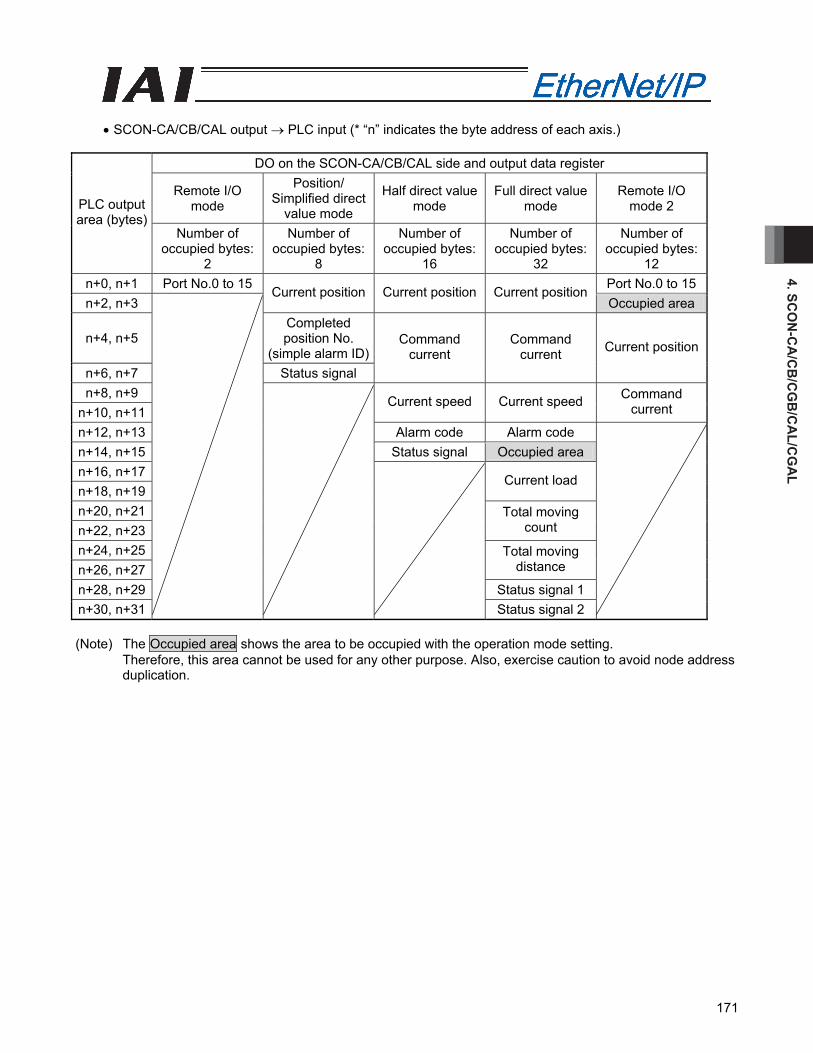
4. SCO
N-C
A/C
B/C
GB
/CA
L/CG
AL
171
• SCON-CA/CB/CAL output → PLC input (* “n” indicates the byte address of each axis.)
DO on the SCON-CA/CB/CAL side and output data register
Remote I/O mode
Position/ Simplified direct
value mode
Half direct value mode
Full direct value mode
Remote I/O mode 2 PLC output
area (bytes) Number of
occupied bytes: 2
Number of occupied bytes:
8
Number of occupied bytes:
16
Number of occupied bytes:
32
Number of occupied bytes:
12 n+0, n+1 Port No.0 to 15 Port No.0 to 15n+2, n+3
Current position Current position Current position Occupied area
n+4, n+5 Completed position No.
(simple alarm ID)n+6, n+7 Status signal
Command current
Command current Current position
n+8, n+9 n+10, n+11
Current speed Current speed Command current
n+12, n+13 Alarm code Alarm code n+14, n+15 Status signal Occupied area n+16, n+17 n+18, n+19
Current load
n+20, n+21 n+22, n+23
Total moving count
n+24, n+25 n+26, n+27
Total moving distance
n+28, n+29 Status signal 1 n+30, n+31
Status signal 2
(Note) The Occupied area shows the area to be occupied with the operation mode setting.
Therefore, this area cannot be used for any other purpose. Also, exercise caution to avoid node address duplication.
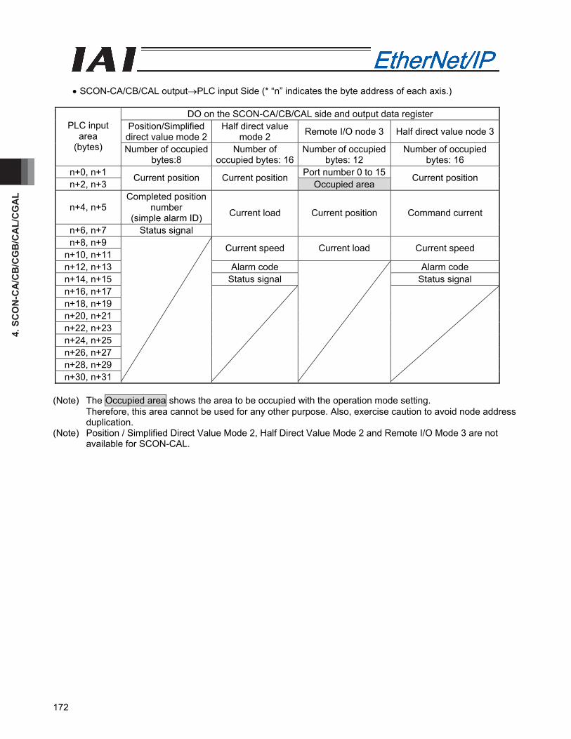
4. S
CO
N-C
A/C
B/C
GB
/CA
L/C
GA
L
172
• SCON-CA/CB/CAL output→PLC input Side (* “n” indicates the byte address of each axis.)
DO on the SCON-CA/CB/CAL side and output data register
Position/Simplified direct value mode 2
Half direct value mode 2 Remote I/O node 3 Half direct value node 3PLC input
area (bytes) Number of occupied
bytes:8 Number of
occupied bytes: 16Number of occupied
bytes: 12 Number of occupied
bytes: 16 n+0, n+1 Port number 0 to 15n+2, n+3
Current position Current position Occupied area
Current position
n+4, n+5 Completed position
number (simple alarm ID)
n+6, n+7 Status signal
Current load Current position Command current
n+8, n+9 n+10, n+11
Current speed Current load Current speed
n+12, n+13 Alarm code Alarm code n+14, n+15 Status signal Status signal n+16, n+17 n+18, n+19 n+20, n+21 n+22, n+23 n+24, n+25 n+26, n+27 n+28, n+29 n+30, n+31
(Note) The Occupied area shows the area to be occupied with the operation mode setting.
Therefore, this area cannot be used for any other purpose. Also, exercise caution to avoid node address duplication.
(Note) Position / Simplified Direct Value Mode 2, Half Direct Value Mode 2 and Remote I/O Mode 3 are not available for SCON-CAL.
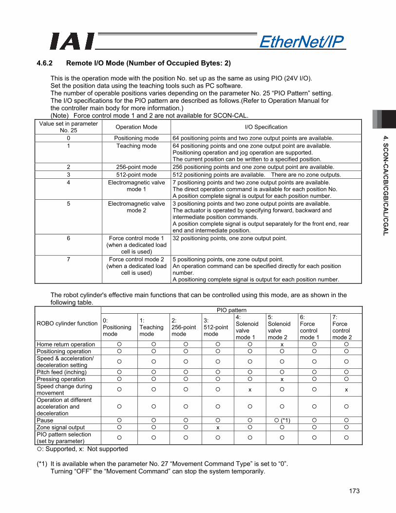
4. SCO
N-C
A/C
B/C
GB
/CA
L/CG
AL
173
4.6.2 Remote I/O Mode (Number of Occupied Bytes: 2)
This is the operation mode with the position No. set up as the same as using PIO (24V I/O). Set the position data using the teaching tools such as PC software. The number of operable positions varies depending on the parameter No. 25 “PIO Pattern” setting. The I/O specifications for the PIO pattern are described as follows.(Refer to Operation Manual for the controller main body for more information.) (Note) Force control mode 1 and 2 are not available for SCON-CAL.
Value set in parameter No. 25 Operation Mode I/O Specification
0 Positioning mode 64 positioning points and two zone output points are available. 1 Teaching mode 64 positioning points and one zone output point are available.
Positioning operation and jog operation are supported. The current position can be written to a specified position.
2 256-point mode 256 positioning points and one zone output point are available. 3 512-point mode 512 positioning points are available. There are no zone outputs. 4 Electromagnetic valve
mode 1 7 positioning points and two zone output points are available. The direct operation command is available for each position No. A position complete signal is output for each position number.
5 Electromagnetic valve mode 2
3 positioning points and two zone output points are available. The actuator is operated by specifying forward, backward and intermediate position commands. A position complete signal is output separately for the front end, rear end and intermediate position.
6 Force control mode 1 (when a dedicated load
cell is used)
32 positioning points, one zone output point.
7 Force control mode 2 (when a dedicated load
cell is used)
5 positioning points, one zone output point. An operation command can be specified directly for each position number. A positioning complete signal is output for each position number.
The robot cylinder's effective main functions that can be controlled using this mode, are as shown in the following table.
PIO pattern
ROBO cylinder function 0: Positioning mode
1: Teaching mode
2: 256-point mode
3: 512-point mode
4: Solenoid valve mode 1
5: Solenoid valve mode 2
6: Force control mode 1
7: Force control mode 2
Home return operation x Positioning operation Speed & acceleration/ deceleration setting
Pitch feed (inching) Pressing operation x Speed change during movement x x
Operation at different acceleration and deceleration
Pause (*1) Zone signal output x PIO pattern selection (set by parameter)
: Supported, x: Not supported (*1) It is available when the parameter No. 27 “Movement Command Type” is set to “0”.
Turning “OFF” the “Movement Command” can stop the system temporarily.
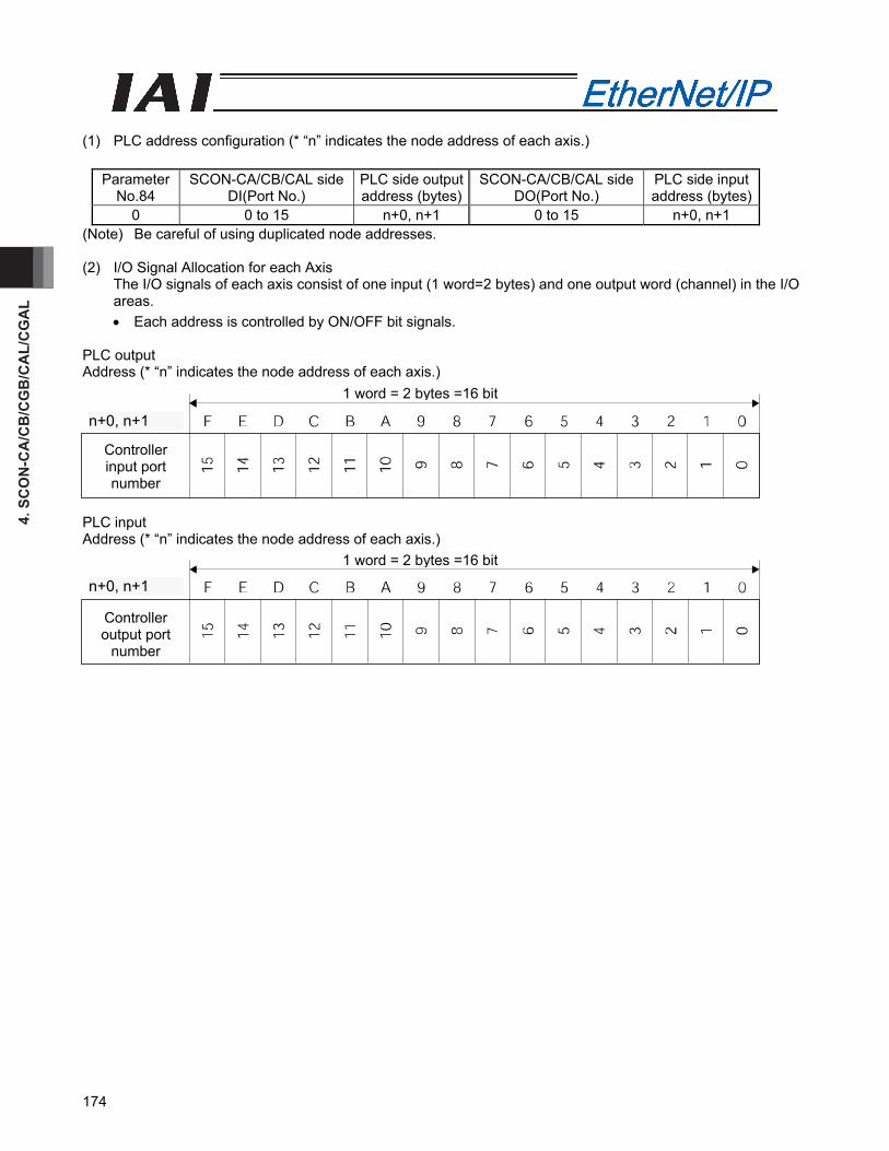
4. S
CO
N-C
A/C
B/C
GB
/CA
L/C
GA
L
174
(1) PLC address configuration (* “n” indicates the node address of each axis.)
Parameter No.84
SCON-CA/CB/CAL side DI(Port No.)
PLC side output address (bytes)
SCON-CA/CB/CAL side DO(Port No.)
PLC side input address (bytes)
0 0 to 15 n+0, n+1 0 to 15 n+0, n+1 (Note) Be careful of using duplicated node addresses. (2) I/O Signal Allocation for each Axis
The I/O signals of each axis consist of one input (1 word=2 bytes) and one output word (channel) in the I/O areas. • Each address is controlled by ON/OFF bit signals.
PLC output Address (* “n” indicates the node address of each axis.) PLC input Address (* “n” indicates the node address of each axis.)
n+0、n+1n+0、n+1
Controller input port number
1 word = 2 bytes =16 bit
n+0, n+1
n+0、n+1
Controller output port
number
n+0, n+1
1 word = 2 bytes =16 bit
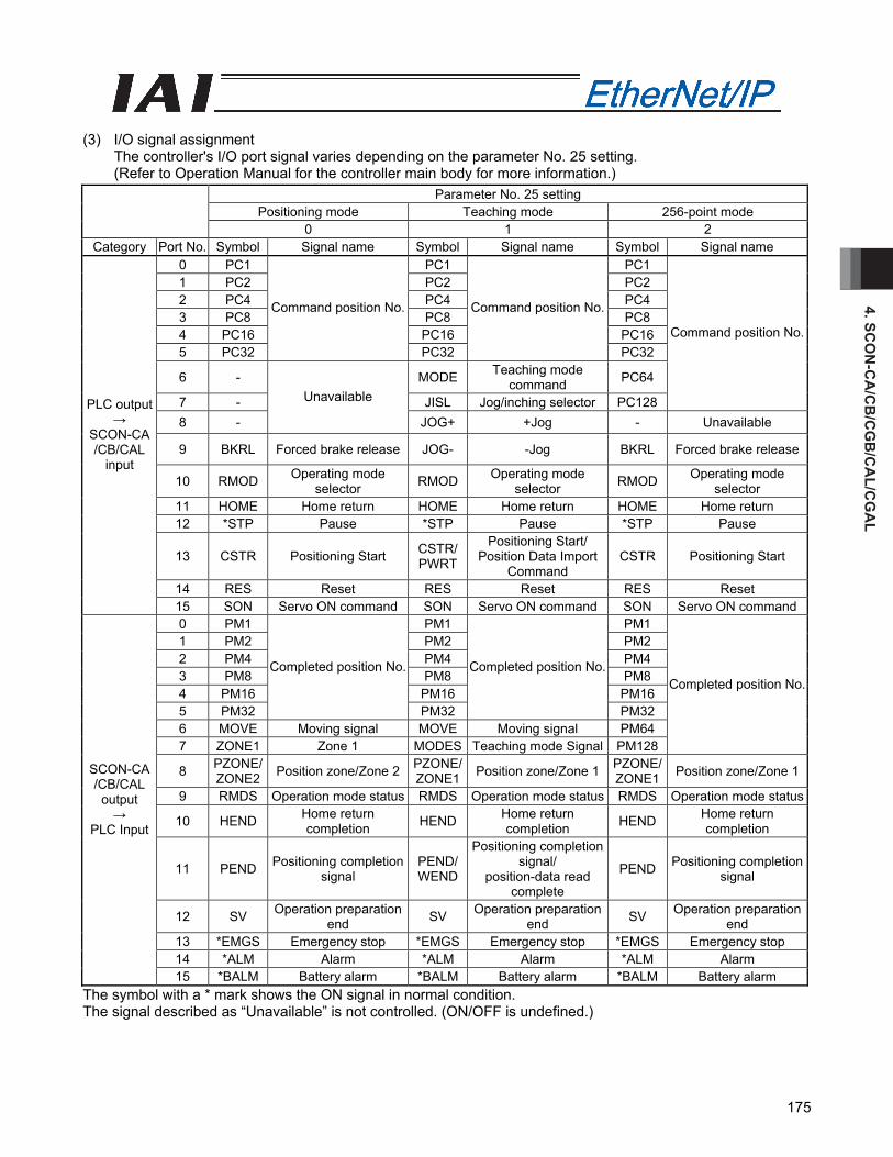
4. SCO
N-C
A/C
B/C
GB
/CA
L/CG
AL
175
(3) I/O signal assignment
The controller's I/O port signal varies depending on the parameter No. 25 setting. (Refer to Operation Manual for the controller main body for more information.)
Parameter No. 25 setting Positioning mode Teaching mode 256-point mode
0 1 2 Category Port No. Symbol Signal name Symbol Signal name Symbol Signal name
0 PC1 PC1 PC1 1 PC2 PC2 PC2 2 PC4 PC4 PC4 3 PC8 PC8 PC8 4 PC16 PC16 PC16 5 PC32
Command position No.
PC32
Command position No.
PC32
6 - MODE Teaching mode command PC64
7 - JISL Jog/inching selector PC128
Command position No.
8 -
Unavailable
JOG+ +Jog - Unavailable
9 BKRL Forced brake release JOG- -Jog BKRL Forced brake release
10 RMOD Operating mode selector RMOD Operating mode
selector RMOD Operating mode selector
11 HOME Home return HOME Home return HOME Home return 12 *STP Pause *STP Pause *STP Pause
13 CSTR Positioning Start CSTR/PWRT
Positioning Start/ Position Data Import
Command CSTR Positioning Start
14 RES Reset RES Reset RES Reset
PLC output →
SCON-CA /CB/CAL
input
15 SON Servo ON command SON Servo ON command SON Servo ON command0 PM1 PM1 PM1 1 PM2 PM2 PM2 2 PM4 PM4 PM4 3 PM8 PM8 PM8 4 PM16 PM16 PM16 5 PM32
Completed position No.
PM32
Completed position No.
PM32 6 MOVE Moving signal MOVE Moving signal PM64 7 ZONE1 Zone 1 MODES Teaching mode Signal PM128
Completed position No.
8 PZONE/ ZONE2 Position zone/Zone 2 PZONE/
ZONE1 Position zone/Zone 1 PZONE/ ZONE1 Position zone/Zone 1
9 RMDS Operation mode status RMDS Operation mode status RMDS Operation mode status
10 HEND Home return completion HEND Home return
completion HEND Home return completion
11 PEND Positioning completion signal
PEND/WEND
Positioning completion signal/
position-data read complete
PEND Positioning completion signal
12 SV Operation preparation end SV Operation preparation
end SV Operation preparation end
13 *EMGS Emergency stop *EMGS Emergency stop *EMGS Emergency stop 14 *ALM Alarm *ALM Alarm *ALM Alarm
SCON-CA /CB/CAL
output →
PLC Input
15 *BALM Battery alarm *BALM Battery alarm *BALM Battery alarm The symbol with a * mark shows the ON signal in normal condition. The signal described as “Unavailable” is not controlled. (ON/OFF is undefined.)
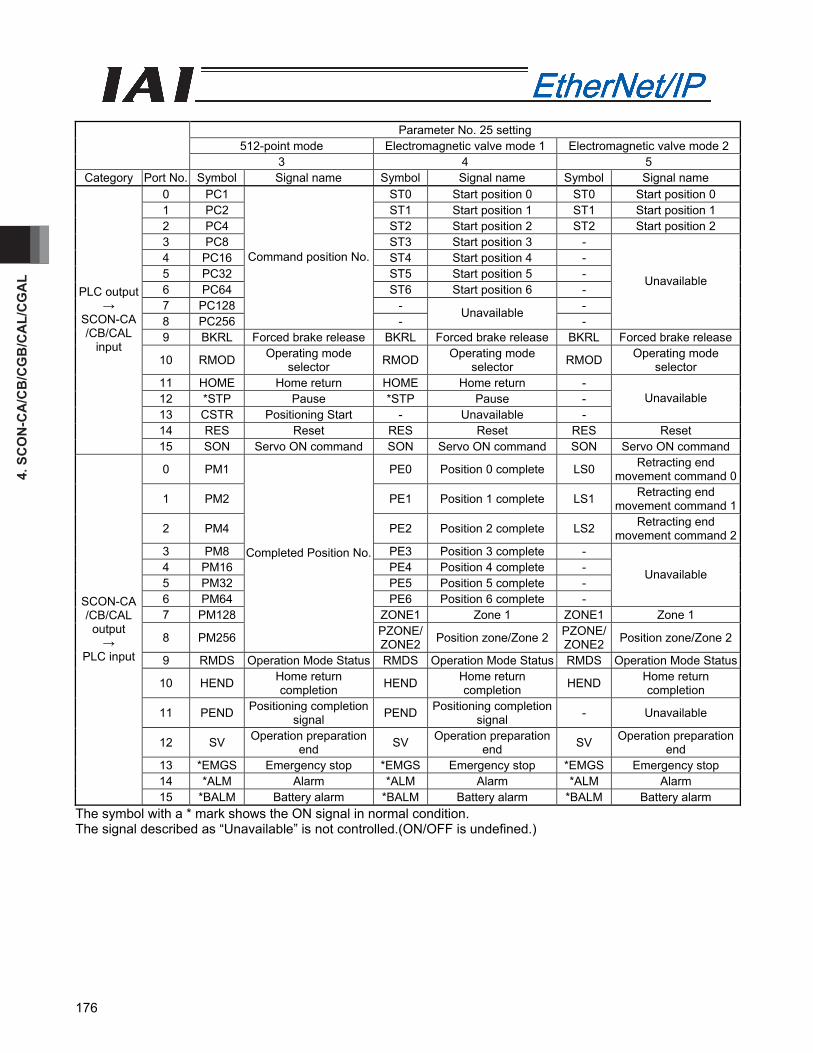
4. S
CO
N-C
A/C
B/C
GB
/CA
L/C
GA
L
176
Parameter No. 25 setting
512-point mode Electromagnetic valve mode 1 Electromagnetic valve mode 2 3 4 5
Category Port No. Symbol Signal name Symbol Signal name Symbol Signal name 0 PC1 ST0 Start position 0 ST0 Start position 0 1 PC2 ST1 Start position 1 ST1 Start position 1 2 PC4 ST2 Start position 2 ST2 Start position 2 3 PC8 ST3 Start position 3 - 4 PC16 ST4 Start position 4 - 5 PC32 ST5 Start position 5 - 6 PC64 ST6 Start position 6 - 7 PC128 - - 8 PC256
Command position No.
- Unavailable
-
Unavailable
9 BKRL Forced brake release BKRL Forced brake release BKRL Forced brake release
10 RMOD Operating mode selector RMOD Operating mode
selector RMOD Operating mode selector
11 HOME Home return HOME Home return - 12 *STP Pause *STP Pause - 13 CSTR Positioning Start - Unavailable -
Unavailable
14 RES Reset RES Reset RES Reset
PLC output →
SCON-CA /CB/CAL
input
15 SON Servo ON command SON Servo ON command SON Servo ON command
0 PM1 PE0 Position 0 complete LS0 Retracting end movement command 0
1 PM2 PE1 Position 1 complete LS1 Retracting end movement command 1
2 PM4 PE2 Position 2 complete LS2 Retracting end movement command 2
3 PM8 PE3 Position 3 complete - 4 PM16 PE4 Position 4 complete - 5 PM32 PE5 Position 5 complete - 6 PM64 PE6 Position 6 complete -
Unavailable
7 PM128 ZONE1 Zone 1 ZONE1 Zone 1
8 PM256
Completed Position No.
PZONE/ZONE2 Position zone/Zone 2 PZONE/
ZONE2 Position zone/Zone 2
9 RMDS Operation Mode Status RMDS Operation Mode Status RMDS Operation Mode Status
10 HEND Home return completion HEND Home return
completion HEND Home return completion
11 PEND Positioning completion signal PEND Positioning completion
signal - Unavailable
12 SV Operation preparation end SV Operation preparation
end SV Operation preparation end
13 *EMGS Emergency stop *EMGS Emergency stop *EMGS Emergency stop 14 *ALM Alarm *ALM Alarm *ALM Alarm
SCON-CA /CB/CAL
output →
PLC input
15 *BALM Battery alarm *BALM Battery alarm *BALM Battery alarm The symbol with a * mark shows the ON signal in normal condition. The signal described as “Unavailable” is not controlled.(ON/OFF is undefined.)

4. SCO
N-C
A/C
B/C
GB
/CA
L/CG
AL
177
Setting of parameter No. 25
Force control mode 1 Force control mode 2 6 7
Category Port No. Symbol Signal name Symbol Signal name 0 PC1 ST0 Start position 0 1 PC2 ST1 Start position 1 2 PC4 ST2 Start position 2 3 PC8 ST3 Start position 3 4 PC16
Command position number
ST4 Start position 4 5 - - 6 - - 7 -
Cannot be used. -
Cannot be used.
8 CLBR Load cell calibration command CLBR Load cell calibration
command 9 BKRL Forced brake release BKRL Forced brake release 10 RMOD Operation mode RMOD Operation mode 11 HOME Home return HOME Home return 12 *STP Pause *STP Pause 13 CSTR Positioning start - Cannot be used. 14 RES Reset RES Reset
PLC output → SCON-CA/CB
input
15 SON Servo ON command SON Servo ON command
0 PM1 PE0 Completed position number 0
1 PM2 PE1 Completed position number 1
2 PM4 PE2 Completed position number 2
3 PM8 PE3 Completed position number 3
4 PM16
Completed position number
PE4 Completed position number 4
5 TRQS Torque level status TRQS Torque level status
6 LOAD Load output judgment status LOAD Load output judgment
status
7 CEND Load cell calibration complete CEND Load cell calibration
complete
8 PZONE/ ZONE1 Position zone/Zone 1 PZONE/
ZONE1 Position zone/Zone 1
9 RMDS Operation mode RMDS Operation mode 10 HEND Home return complete HEND Home return complete 11 PEND Positioning complete signal PEND Positioning complete signal12 SV Operation ready SV Operation ready 13 *EMGS Emergency stop *EMGS Emergency stop 14 *ALM Alarm *ALM Alarm
SCON-CA/CB output
→ PLC input
15 *BALM Battery alarm *BALM Battery alarm The symbol with a * mark shows the ON signal in normal condition. The signal described as “Unavailable” is not controlled.(ON/OFF is undefined.) (Note) Force control mode 1 and 2 are not available for SCON-CAL.
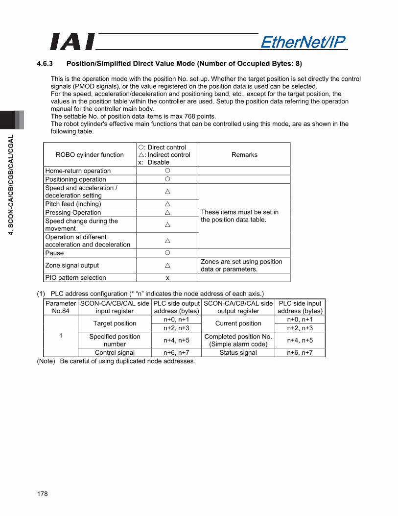
4. S
CO
N-C
A/C
B/C
GB
/CA
L/C
GA
L
178
4.6.3 Position/Simplified Direct Value Mode (Number of Occupied Bytes: 8)
This is the operation mode with the position No. set up. Whether the target position is set directly the control signals (PMOD signals), or the value registered on the position data is used can be selected. For the speed, acceleration/deceleration and positioning band, etc., except for the target position, the values in the position table within the controller are used. Setup the position data referring the operation manual for the controller main body. The settable No. of position data items is max 768 points. The robot cylinder's effective main functions that can be controlled using this mode, are as shown in the following table.
ROBO cylinder function : Direct control : Indirect control
x: Disable Remarks
Home-return operation Positioning operation Speed and acceleration / deceleration setting
Pitch feed (inching) Pressing Operation Speed change during the movement
Operation at different acceleration and deceleration
These items must be set in the position data table.
Pause
Zone signal output Zones are set using position data or parameters.
PIO pattern selection x (1) PLC address configuration (* “n” indicates the node address of each axis.)
ParameterNo.84
SCON-CA/CB/CAL side input register
PLC side output address (bytes)
SCON-CA/CB/CAL sideoutput register
PLC side input address (bytes)
n+0, n+1 n+0, n+1 Target position n+2, n+3
Current position n+2, n+3
Specified position number n+4, n+5 Completed position No.
(Simple alarm code) n+4, n+5 1
Control signal n+6, n+7 Status signal n+6, n+7 (Note) Be careful of using duplicated node addresses.
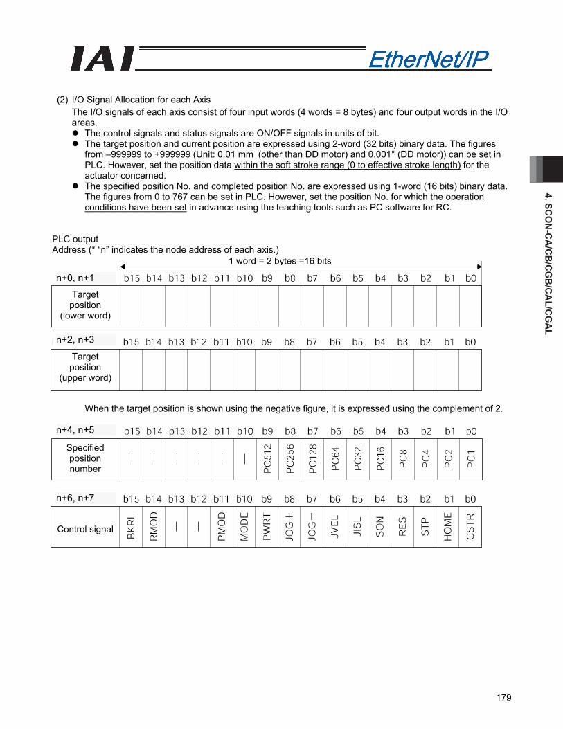
4. SCO
N-C
A/C
B/C
GB
/CA
L/CG
AL
179
(2) I/O Signal Allocation for each Axis
The I/O signals of each axis consist of four input words (4 words = 8 bytes) and four output words in the I/O areas.
The control signals and status signals are ON/OFF signals in units of bit. The target position and current position are expressed using 2-word (32 bits) binary data. The figures
from –999999 to +999999 (Unit: 0.01 mm (other than DD motor) and 0.001° (DD motor)) can be set in PLC. However, set the position data within the soft stroke range (0 to effective stroke length) for the actuator concerned.
The specified position No. and completed position No. are expressed using 1-word (16 bits) binary data. The figures from 0 to 767 can be set in PLC. However, set the position No. for which the operation conditions have been set in advance using the teaching tools such as PC software for RC.
PLC output Address (* “n” indicates the node address of each axis.)
When the target position is shown using the negative figure, it is expressed using the complement of 2.
n+4、n+5
n+6、n+7
Specified position number
Control signal
n+6, n+7
n+4, n+5
1 word = 2 bytes =16 bits
n+0、n+1
n+2、n+3
Target position
(lower word)
Target position
(upper word)
n+2, n+3
n+0, n+1
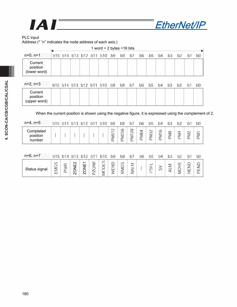
4. S
CO
N-C
A/C
B/C
GB
/CA
L/C
GA
L
180
PLC input Address (* “n” indicates the node address of each axis.)
When the current position is shown using the negative figure, it is expressed using the complement of 2.
n+4、n+5
n+6、n+7
Completed position number
Status signal
n+6, n+7
n+4, n+5
1 word = 2 bytes =16 bits
n+0、n+1
n+2、n+3
Current position
(lower word)
Current position
(upper word)
n+2, n+3
n+0, n+1
ZON
E1
ZON
E2
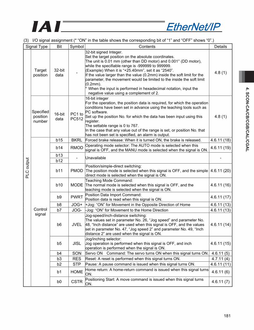
4. SCO
N-C
A/C
B/C
GB
/CA
L/CG
AL
181
(3) I/O signal assignment (* “ON” in the table shows the corresponding bit of “1” and “OFF” shows “0”.) Signal Type Bit Symbol Contents Details
Target position
32-bit data -
32-bit signed Integer. Set the target position on the absolute coordinates. The unit is 0.01 mm (other than DD motor) and 0.001° (DD motor), while the specifiable range is -999999 to 999999. (Example) When it is “+25.40mm”, set it as “2540”. If the value larger than the value (0.2mm) inside the soft limit for the parameter, the movement would be limited to the inside the soft limit (0.2mm). * When the input is performed in hexadecimal notation, input the
negative value using a complement of 2.
4.8 (1)
Specified position number
16-bit data
PC1 to PC512
16-bit integer For the operation, the position data is required, for which the operation conditions have been set in advance using the teaching tools such as PC software. Set up the position No. for which the data has been input using this register. The settable range is 0 to 767. In the case that any value out of the range is set, or position No. that has not been set is specified, an alarm is output.
4.8 (1)
b15 BKRL Forced brake release: When it is turned ON, the brake is released. 4.6.11 (18)
b14 RMOD Operating mode selector: The AUTO mode is selected when this signal is OFF, and the MANU mode is selected when the signal is ON. 4.6.11 (19)
b13 b12
- Unavailable -
b11 PMOD Position/simple-direct switching: The position mode is selected when this signal is OFF, and the simple direct mode is selected when the signal is ON.
4.6.11 (20)
b10 MODE Teaching Mode Command: The normal mode is selected when this signal is OFF, and the teaching mode is selected when the signal is ON.
4.6.11 (16)
b9 PWRT Position Data Import Command: Position data is read when this signal is ON. 4.6.11 (17)
b8 JOG+ +Jog: “ON” for Movement in the Opposite Direction of Home 4.6.11 (13)b7 JOG- -Jog: “ON” for Movement to the Home Direction 4.6.11 (13)
b6 JVEL
Jog-speed/inch-distance switching: The values set in parameter No. 26, “Jog speed” and parameter No. 48, “Inch distance” are used when this signal is OFF, and the values set in parameter No. 47, “Jog speed 2” and parameter No. 49, “Inch distance 2” are used when the signal is ON.
4.6.11 (14)
b5 JISL Jog/inching selector: Jog operation is performed when this signal is OFF, and inch operation is performed when the signal is ON.
4.6.11 (15)
b4 SON Servo ON Command: The servo turns ON when this signal turns ON. 4.6.11 (5)b3 RES Reset: A reset is performed when this signal turns ON. 4.7.11 (4)b2 STP Pause: A pause command is issued when this signal turns ON. 4.6.11 (11)
b1 HOME Home return: A home-return command is issued when this signal turns ON. 4.6.11 (6)
PLC
out
put
Control signal
b0 CSTR Positioning Start: A move command is issued when this signal turns ON. 4.6.11 (7)
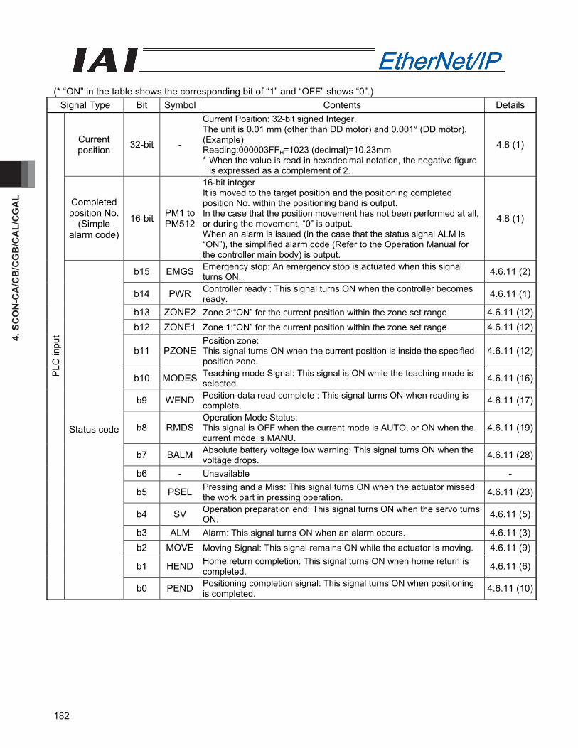
4. S
CO
N-C
A/C
B/C
GB
/CA
L/C
GA
L
182
(* “ON” in the table shows the corresponding bit of “1” and “OFF” shows “0”.)
Signal Type Bit Symbol Contents Details
Current position 32-bit -
Current Position: 32-bit signed Integer. The unit is 0.01 mm (other than DD motor) and 0.001° (DD motor). (Example) Reading:000003FFH=1023 (decimal)=10.23mm * When the value is read in hexadecimal notation, the negative figure
is expressed as a complement of 2.
4.8 (1)
Completed position No.
(Simple alarm code)
16-bit PM1 to PM512
16-bit integer It is moved to the target position and the positioning completed position No. within the positioning band is output. In the case that the position movement has not been performed at all, or during the movement, “0” is output. When an alarm is issued (in the case that the status signal ALM is “ON”), the simplified alarm code (Refer to the Operation Manual for the controller main body) is output.
4.8 (1)
b15 EMGS Emergency stop: An emergency stop is actuated when this signal turns ON. 4.6.11 (2)
b14 PWR Controller ready : This signal turns ON when the controller becomes ready. 4.6.11 (1)
b13 ZONE2 Zone 2:“ON” for the current position within the zone set range 4.6.11 (12)b12 ZONE1 Zone 1:“ON” for the current position within the zone set range 4.6.11 (12)
b11 PZONE Position zone: This signal turns ON when the current position is inside the specified position zone.
4.6.11 (12)
b10 MODES Teaching mode Signal: This signal is ON while the teaching mode is selected. 4.6.11 (16)
b9 WEND Position-data read complete : This signal turns ON when reading is complete. 4.6.11 (17)
b8 RMDS Operation Mode Status: This signal is OFF when the current mode is AUTO, or ON when the current mode is MANU.
4.6.11 (19)
b7 BALM Absolute battery voltage low warning: This signal turns ON when the voltage drops. 4.6.11 (28)
b6 - Unavailable -
b5 PSEL Pressing and a Miss: This signal turns ON when the actuator missed the work part in pressing operation. 4.6.11 (23)
b4 SV Operation preparation end: This signal turns ON when the servo turns ON. 4.6.11 (5)
b3 ALM Alarm: This signal turns ON when an alarm occurs. 4.6.11 (3)b2 MOVE Moving Signal: This signal remains ON while the actuator is moving. 4.6.11 (9)
b1 HEND Home return completion: This signal turns ON when home return is completed. 4.6.11 (6)
PLC
inpu
t
Status code
b0 PEND Positioning completion signal: This signal turns ON when positioning is completed. 4.6.11 (10)
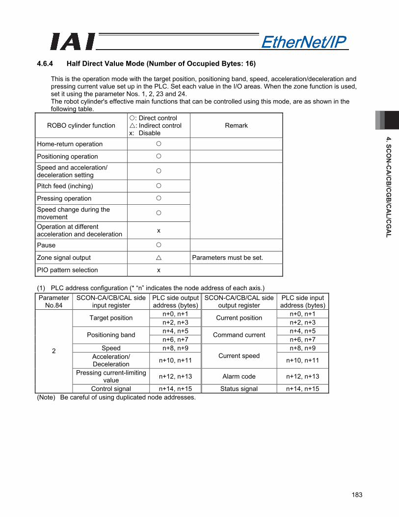
4. SCO
N-C
A/C
B/C
GB
/CA
L/CG
AL
183
4.6.4 Half Direct Value Mode (Number of Occupied Bytes: 16)
This is the operation mode with the target position, positioning band, speed, acceleration/deceleration and pressing current value set up in the PLC. Set each value in the I/O areas. When the zone function is used, set it using the parameter Nos. 1, 2, 23 and 24. The robot cylinder's effective main functions that can be controlled using this mode, are as shown in the following table.
ROBO cylinder function : Direct control : Indirect control
x: Disable Remark
Home-return operation
Positioning operation
Speed and acceleration/ deceleration setting
Pitch feed (inching)
Pressing operation
Speed change during the movement
Operation at different acceleration and deceleration x
Pause
Zone signal output Parameters must be set.
PIO pattern selection x (1) PLC address configuration (* “n” indicates the node address of each axis.) Parameter
No.84 SCON-CA/CB/CAL side
input register PLC side output address (bytes)
SCON-CA/CB/CAL sideoutput register
PLC side input address (bytes)
n+0, n+1 n+0, n+1 Target position n+2, n+3
Current position n+2, n+3
n+4, n+5 n+4, n+5 Positioning band n+6, n+7
Command current n+6, n+7
Speed n+8, n+9 n+8, n+9 Acceleration/ Deceleration n+10, n+11
Current speed n+10, n+11
Pressing current-limiting value n+12, n+13 Alarm code n+12, n+13
2
Control signal n+14, n+15 Status signal n+14, n+15 (Note) Be careful of using duplicated node addresses.
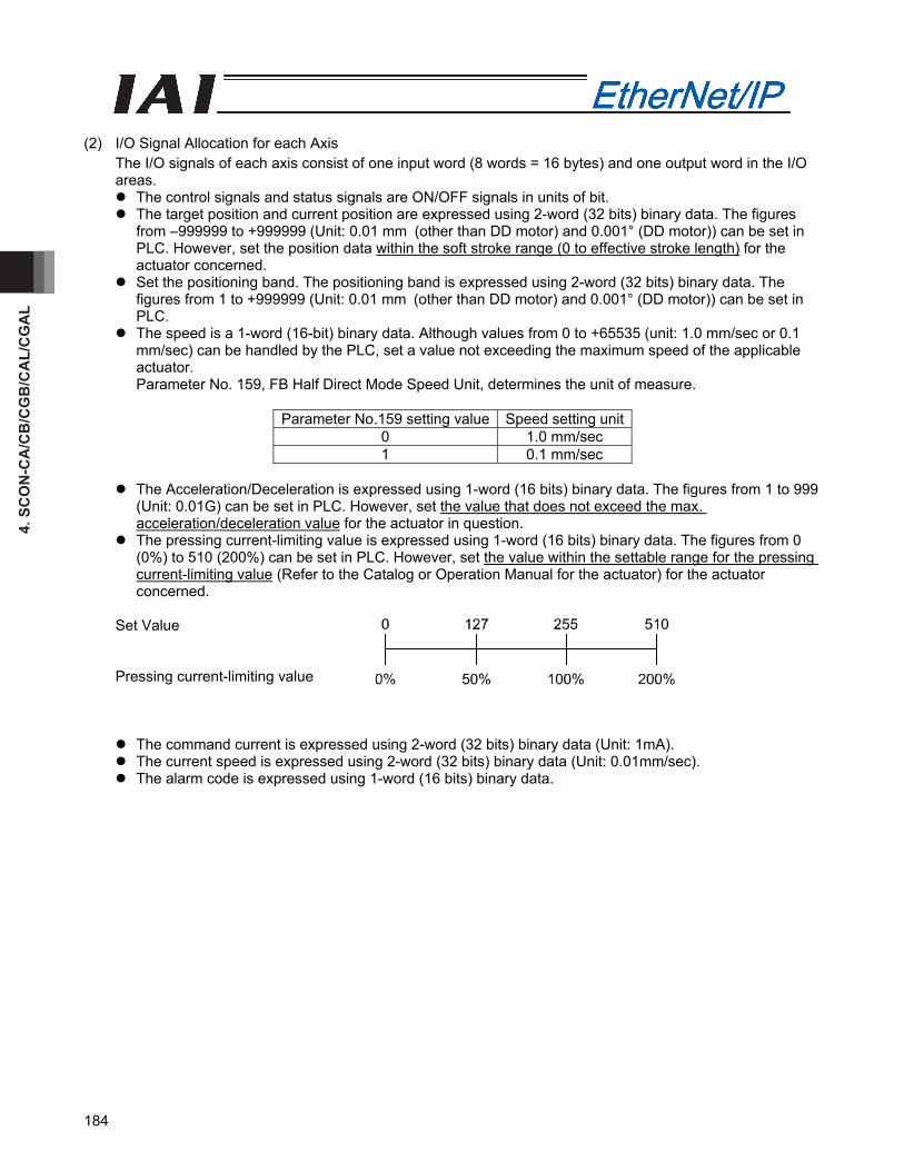
4. S
CO
N-C
A/C
B/C
GB
/CA
L/C
GA
L
184
(2) I/O Signal Allocation for each Axis
The I/O signals of each axis consist of one input word (8 words = 16 bytes) and one output word in the I/O areas.
The control signals and status signals are ON/OFF signals in units of bit. The target position and current position are expressed using 2-word (32 bits) binary data. The figures
from –999999 to +999999 (Unit: 0.01 mm (other than DD motor) and 0.001° (DD motor)) can be set in PLC. However, set the position data within the soft stroke range (0 to effective stroke length) for the actuator concerned.
Set the positioning band. The positioning band is expressed using 2-word (32 bits) binary data. The figures from 1 to +999999 (Unit: 0.01 mm (other than DD motor) and 0.001° (DD motor)) can be set in PLC.
The speed is a 1-word (16-bit) binary data. Although values from 0 to +65535 (unit: 1.0 mm/sec or 0.1 mm/sec) can be handled by the PLC, set a value not exceeding the maximum speed of the applicable actuator. Parameter No. 159, FB Half Direct Mode Speed Unit, determines the unit of measure.
Parameter No.159 setting value Speed setting unit0 1.0 mm/sec 1 0.1 mm/sec
The Acceleration/Deceleration is expressed using 1-word (16 bits) binary data. The figures from 1 to 999
(Unit: 0.01G) can be set in PLC. However, set the value that does not exceed the max. acceleration/deceleration value for the actuator in question.
The pressing current-limiting value is expressed using 1-word (16 bits) binary data. The figures from 0 (0%) to 510 (200%) can be set in PLC. However, set the value within the settable range for the pressing current-limiting value (Refer to the Catalog or Operation Manual for the actuator) for the actuator concerned.
Set Value Pressing current-limiting value
The command current is expressed using 2-word (32 bits) binary data (Unit: 1mA). The current speed is expressed using 2-word (32 bits) binary data (Unit: 0.01mm/sec). The alarm code is expressed using 1-word (16 bits) binary data.

4. SCO
N-C
A/C
B/C
GB
/CA
L/CG
AL
185
PLC output Address (* “n” indicates the node address of each axis.)
When the target position is shown using the negative figure, it is expressed using the complement of 2.
1 word = 2 bytes =16 bits
Target position
(lower word)
Target position
(upper word)
n+2, n+3
n+0, n+1
Positioning band
(lower word)
Positioning band
(upper word)
Speed
Acceleration/ deceleration
Pressing current-limiting
value
Control signal
n+14, n+15
n+12, n+13
n+10, n+11
n+8, n+9
n+6, n+7
n+4, n+5
1,02
4
512
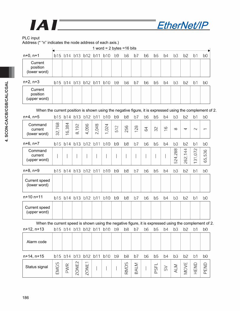
4. S
CO
N-C
A/C
B/C
GB
/CA
L/C
GA
L
186
PLC input Address (* “n” indicates the node address of each axis.)
When the current position is shown using the negative figure, it is expressed using the complement of 2.
When the current speed is shown using the negative figure, it is expressed using the complement of 2.
1 word = 2 bytes =16 bits
Current position
(lower word)
Current position
(upper word)
n+2, n+3
n+0, n+1
Command current
(lower word)
Command current
(upper word)
Current speed (lower word)
Current speed (upper word)
n+10 n+11
n+8, n+9
n+6, n+7
n+4, n+5
Alarm code
Status signal
n+14, n+15
n+12, n+13

4. SCO
N-C
A/C
B/C
GB
/CA
L/CG
AL
187
(3) I/O signal assignment (* “ON” in the table shows the corresponding bit of “1” and “OFF” shows “0”.)
Signal type Bit Symbol Contents Details
Target position
32-bit data -
32-bit signed Integer. Set the target position on the absolute coordinates. The unit is 0.01 mm (other than DD motor) and 0.001° (DD motor), while the specifiable range is -999999 to 999999. (Example) When it is “+25.41mm”, set it as “2541”. If the value larger than the value (0.2mm) inside the soft limit for the parameter, the movement would be limited to the inside the soft limit (0.2mm). * When the input is performed in hexadecimal notation, input
the negative value using a complement of 2.
4.8 (2)
Positioning band
32-bit data -
32-bit integer The unit is 0.01 mm (other than DD motor) and 0.001° (DD motor), while the specifiable range is 1 to 999999. (Example) When it is “25.40mm”, set it as “2540”. This register value has two meanings depending on the operation type. 1) In the case of positioning operation, it shows the allowable range from the target position, that is regarded as the positioning completion. 2) In the case of pressing operation, it shows the pressing width value. Specify the normal operation or pressing operation using the “PUSH” control signal setting.
4.8 (2)
Speed 16-bit data -
16-bit integer. Specify the speed at which to move the actuator. Designate the unit of 1.0mm/sec or 0.1mm/sec. The settable range is 0 to 65535. Deceleration stop if and to specify in motion 0. It under suspension, it will remain stopped on the spot. Unit of measure is selected by Parameter No. 159 FB Half Direct Mode Speed Unit. (Example) In the case of the unit of 1.0mm/sec: To set 254.0 mm/sec, specify “254.” If a move command is issued by specifying a value exceeding the maximum speed, an alarm will occur.
4.8 (2)
PLC
out
put
Acceleration/ deceleration
16-bit data -
16-bit integer Specify the acceleration / deceleration at which to move the actuator (the acceleration and deceleration will be the same value). The unit is 0.01G and settable range is 1 to 999. (Example) To set “0.30 G”, specify “30”. If a move command is issued by specifying “0” or any value exceeding the maximum acceleration or deceleration, an alarm will occur.
4.8 (2)

4. S
CO
N-C
A/C
B/C
GB
/CA
L/C
GA
L
188
(* “ON” in the table shows the corresponding bit of “1” and “OFF” shows “0”.)
Signal type Bit Symbol Contents Details
Pressing current-limiting
value
16-bit data -
16-bit integer Specify the current-limiting value to be used during pressing operation. The allowable specification range is 0 (0%) to 255 (100%). The actual settable range varies depending on each actuator.(Refer to the catalog or Operation Manual for the actuator.) If a move command is issued by specifying a value exceeding the maximum pressing current, an alarm will occur.
4.8 (2)
b15 BKRL Forced brake release: When it is turned ON, the brake is released. 4.6.11 (18)
b14 RMOD Operating mode selector: The AUTO mode is selected when this signal is OFF, and the MANU mode is selected when the signal is ON. 4.6.11 (19)
b13 DIR
Pressing direction specification: “OFF” for the direction reducing the positioning band from the target position, “ON” for the direction adding the positioning band to the target position
4.6.11 (22)
b12 PUSH Pressing specification: Positioning operation is performed when this signal is OFF, and pressing operation is performed when the signal is ON.
4.6.11 (21)
b11 GSL1 Servo gain parameter set selection 1
b10 GSL0 Servo gain parameter set selection 0
Select the servo gain parameter set to be used.GSL1 GSL0 Function OFF OFF Select parameter set 0. OFF ON Select parameter set 1. ON OFF Select parameter set 2. ON ON Select parameter set 3.
4.6.11 (33)
b9 - Cannot be used. - b8 JOG+ + Jog: “ON” for Movement in the Opposite Direction of Home 4.6.11 (13)b7 JOG- -Jog: “ON” for Movement to the Home Direction 4.6.11 (13)
b6 JVEL
Jog-speed/inch-distance switching: The values set in parameter No. 26, “Jog speed” and parameter No. 48, “Inch distance” are used when this signal is OFF, and the values set in parameter No. 47, “Jog speed 2” and parameter No. 49, “Inch distance 2” are used when the signal is ON.
4.6.11 (14)
b5 JISL Jog/inch switching: Jog operation is performed when this signal is OFF, and inch operation is performed when the signal is ON.
4.6.11 (15)
b4 SON Servo ON Command: The servo turns ON when this signal turns ON. 4.6.11 (5) b3 RES Reset: A reset is performed when this signal turns ON. 4.6.11 (4) b2 STP Pause: A pause command is issued when this signal turns ON. 4.6.11 (11)
b1 HOME Home return: A home-return command is issued when this signal turns ON. 4.6.11 (6)
PLC
out
put
Control signal
b0 DSTR Positioning Command: A move command is issued when this signal turns ON. 4.6.11 (8)

4. SCO
N-C
A/C
B/C
GB
/CA
L/CG
AL
189
(* “ON” in the table shows the corresponding bit of “1” and “OFF” shows “0”.)
Signal type Bit Symbol Contents Details
Current position
32-bit data -
32-bit signed integer indicating the current position The unit is 0.01 mm (other than DD motor) and 0.001° (DD motor). (Example) Reading: 000003FFH=1023 (decimal)
=10.23mm * When the value is read in hexadecimal notation, the negative figure
is expressed as a complement of 2.
4.8 (2)
Command current
32-bit data -
32-bit integer The electrical current presently specified by a command is indicated. The setting unit is mA. (Example) Reading: 000003FFH=1023 (decimal)
=1023mA
4.8 (2)
Current speed
32-bit data -
32-bit signed integer indicating the current position The current speed is indicated. Positive value: The actuator is moving in the direction opposite home. Negative value: The actuator is moving in the direction of home. The setting unit is 0.01mm/sec. (Example) Reading: 000003FFH=1023 (decimal)
=10.23mm/sec * When the value is read in hexadecimal notation, the negative figure
is expressed as a complement of 2.
4.8 (2)
Alarm code 16-bit data -
16-bit integer When an alarm is issued, the alarm code is output. When any alarm is not issued, it is “0H”. Refer to the Operation Manual for the controller main body for the details of the alarms.
4.8 (2)
b15 EMGS Emergency stop: An emergency stop is actuated when this signal turns ON. 4.6.11 (2)
b14 PWR Controller ready : This signal turns ON when the controller becomes ready. 4.6.11 (1)
b13 ZONE2 Zone 2:“ON” for the current position within the zone set range 4.6.11 (12)
b12 ZONE1 Zone 1:“ON” for the current position within the zone set range 4.6.11 (12)
b11
b10
b9
- Unavailable -
b8 RMDS Operation Mode Status: This signal is OFF when the current mode is AUTO, or ON when the current mode is MANU.
4.6.11 (19)
b7 BALM Absolute battery voltage low warning: This signal turns ON when the voltage drops. 4.6.11 (28)
b6 - Cannot be used. -
b5 PSEL Pressing and a Miss: This signal turns ON when the actuator missed the work part in pressing operation. 4.6.11 (23)
b4 SV Operation preparation end: This signal turns ON when the servo turns ON. 4.6.11 (5)
b3 ALM Alarm: This signal turns ON when an alarm occurs. 4.6.11 (3) b2 MOVE Moving Signal: This signal remains ON while the actuator is moving. 4.6.11 (9)
b1 HEND Home return completion: This signal turns ON when home return is completed. 4.6.11 (6)
PLC
inpu
t
Status signal
b0 PEND Positioning completion signal: This signal turns ON when positioning is completed. 4.6.11 (10)
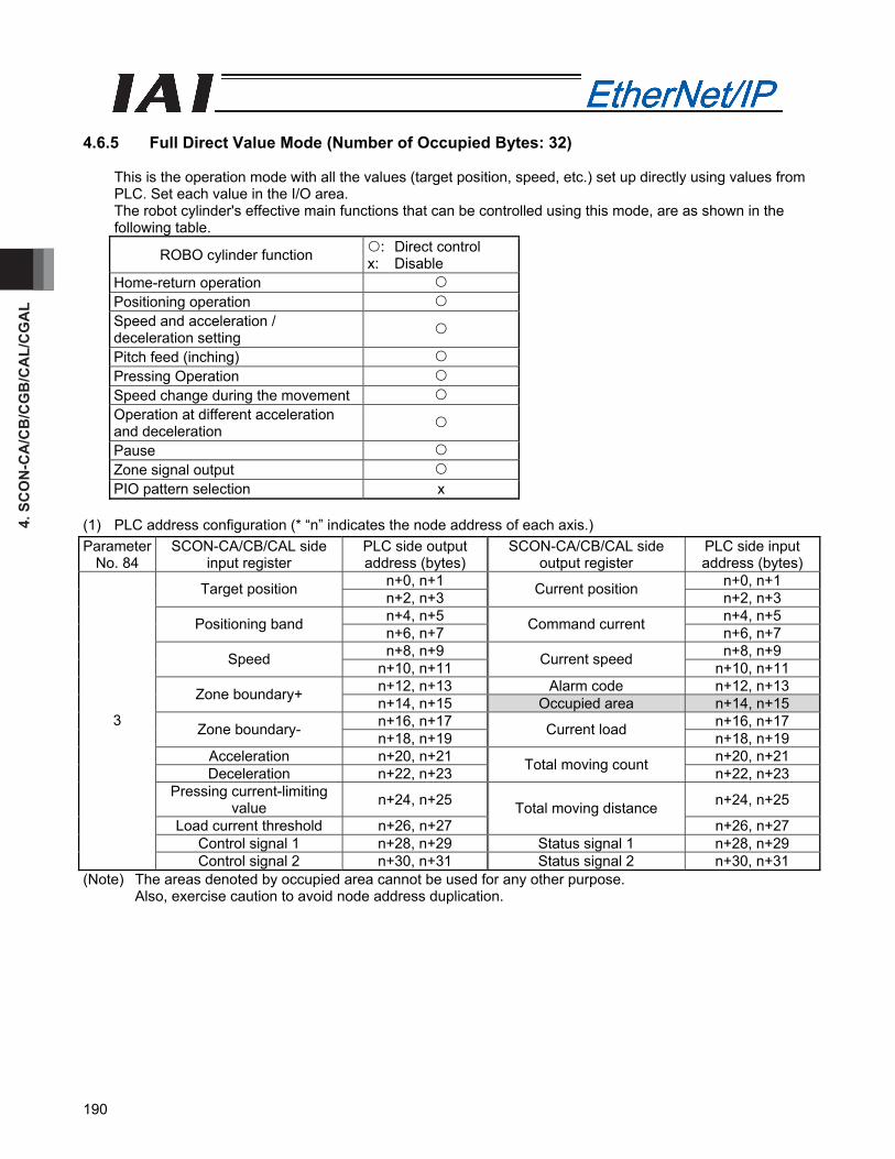
4. S
CO
N-C
A/C
B/C
GB
/CA
L/C
GA
L
190
4.6.5 Full Direct Value Mode (Number of Occupied Bytes: 32)
This is the operation mode with all the values (target position, speed, etc.) set up directly using values from PLC. Set each value in the I/O area. The robot cylinder's effective main functions that can be controlled using this mode, are as shown in the following table.
ROBO cylinder function : Direct control x: Disable
Home-return operation Positioning operation Speed and acceleration / deceleration setting
Pitch feed (inching) Pressing Operation Speed change during the movement Operation at different acceleration and deceleration
Pause Zone signal output PIO pattern selection x
(1) PLC address configuration (* “n” indicates the node address of each axis.) Parameter
No. 84 SCON-CA/CB/CAL side
input register PLC side output address (bytes)
SCON-CA/CB/CAL side output register
PLC side input address (bytes)
n+0, n+1 n+0, n+1 Target position n+2, n+3 Current position n+2, n+3 n+4, n+5 n+4, n+5 Positioning band n+6, n+7 Command current n+6, n+7 n+8, n+9 n+8, n+9 Speed n+10, n+11 Current speed n+10, n+11
n+12, n+13 Alarm code n+12, n+13 Zone boundary+ n+14, n+15 Occupied area n+14, n+15 n+16, n+17 n+16, n+17 Zone boundary- n+18, n+19 Current load n+18, n+19
Acceleration n+20, n+21 n+20, n+21 Deceleration n+22, n+23 Total moving count n+22, n+23
Pressing current-limiting value n+24, n+25 n+24, n+25
Load current threshold n+26, n+27 Total moving distance
n+26, n+27 Control signal 1 n+28, n+29 Status signal 1 n+28, n+29
3
Control signal 2 n+30, n+31 Status signal 2 n+30, n+31 (Note) The areas denoted by occupied area cannot be used for any other purpose.
Also, exercise caution to avoid node address duplication.
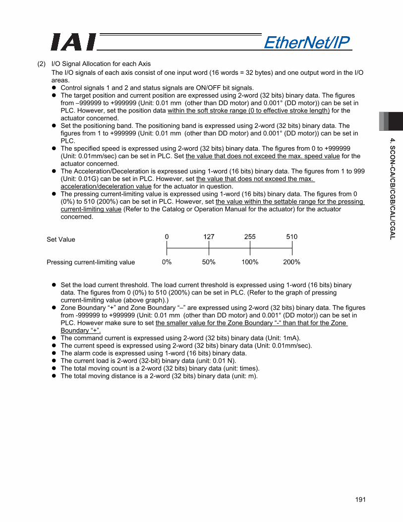
4. SCO
N-C
A/C
B/C
GB
/CA
L/CG
AL
191
(2) I/O Signal Allocation for each Axis
The I/O signals of each axis consist of one input word (16 words = 32 bytes) and one output word in the I/O areas.
Control signals 1 and 2 and status signals are ON/OFF bit signals. The target position and current position are expressed using 2-word (32 bits) binary data. The figures
from –999999 to +999999 (Unit: 0.01 mm (other than DD motor) and 0.001° (DD motor)) can be set in PLC. However, set the position data within the soft stroke range (0 to effective stroke length) for the actuator concerned.
Set the positioning band. The positioning band is expressed using 2-word (32 bits) binary data. The figures from 1 to +999999 (Unit: 0.01 mm (other than DD motor) and 0.001° (DD motor)) can be set in PLC.
The specified speed is expressed using 2-word (32 bits) binary data. The figures from 0 to +999999 (Unit: 0.01mm/sec) can be set in PLC. Set the value that does not exceed the max. speed value for the actuator concerned.
The Acceleration/Deceleration is expressed using 1-word (16 bits) binary data. The figures from 1 to 999 (Unit: 0.01G) can be set in PLC. However, set the value that does not exceed the max. acceleration/deceleration value for the actuator in question.
The pressing current-limiting value is expressed using 1-word (16 bits) binary data. The figures from 0 (0%) to 510 (200%) can be set in PLC. However, set the value within the settable range for the pressing current-limiting value (Refer to the Catalog or Operation Manual for the actuator) for the actuator concerned.
Set Value Pressing current-limiting value
Set the load current threshold. The load current threshold is expressed using 1-word (16 bits) binary data. The figures from 0 (0%) to 510 (200%) can be set in PLC. (Refer to the graph of pressing current-limiting value (above graph).)
Zone Boundary “+” and Zone Boundary “–” are expressed using 2-word (32 bits) binary data. The figures from -999999 to +999999 (Unit: 0.01 mm (other than DD motor) and 0.001° (DD motor)) can be set in PLC. However make sure to set the smaller value for the Zone Boundary “-“ than that for the Zone Boundary “+”.
The command current is expressed using 2-word (32 bits) binary data (Unit: 1mA). The current speed is expressed using 2-word (32 bits) binary data (Unit: 0.01mm/sec). The alarm code is expressed using 1-word (16 bits) binary data. The current load is 2-word (32-bit) binary data (unit: 0.01 N). The total moving count is a 2-word (32 bits) binary data (unit: times). The total moving distance is a 2-word (32 bits) binary data (unit: m).

4. S
CO
N-C
A/C
B/C
GB
/CA
L/C
GA
L
192
PLC output Address (* “n” indicates the node address of each axis.)
When the target position is shown using the negative figure, it is expressed using the complement of 2.
When the zone boundary is shown using the negative figure, it is expressed using the complement of 2.
n+4、n+5
n+6、n+7
n+8、n+9
n+10、n+11
n+12、n+13
n+14、n+15
Positioning band
(lower word)
Positioning band
(upper word)
Speed (lower word)
Speed (upper word)
Zone boundary + (lower word)
Zone boundary +
(upper word)
n+14, n+15
n+12, n+13
n+10, n+11
n+8, n+9
n+6, n+7
n+4, n+5
1 word = 2 bytes =16 bits
n+0、n+1
n+2、n+3
Target position
(lower word)
Target position
(upper word)
n+2, n+3
n+0, n+1

4. SCO
N-C
A/C
B/C
GB
/CA
L/CG
AL
193
Address (* “n” indicates the node address of each axis.)
When the zone boundary is shown using the negative figure, it is expressed using the complement of 2. * Applicable only for SCON-CA/CB
n+20、n+21
n+22、n+23
n+24、n+25
n+26、n+27
n+28、n+29
n+30、n+31
Acceleration
Deceleration
Pressing current-limiting
Load current threshold
(*3)
Control signal 1
Control signal 2
n+30, n+31
n+28, n+29
n+26, n+27
n+24, n+25
n+22, n+23
n+20, n+21
1 word = 2 bytes =16 bits
n+16、n+17
n+18、n+19
Zone boundary -
(lower word)
Zone boundary -
(upper word)
n+18, n+19
n+16, n+17
CLB
R*
1,02
4
512
1,02
4
512
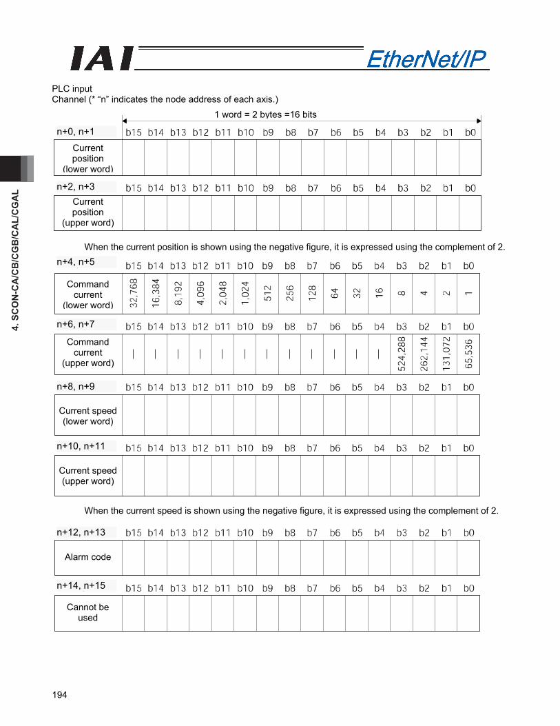
4. S
CO
N-C
A/C
B/C
GB
/CA
L/C
GA
L
194
PLC input Channel (* “n” indicates the node address of each axis.)
When the current position is shown using the negative figure, it is expressed using the complement of 2.
When the current speed is shown using the negative figure, it is expressed using the complement of 2.
n+12、n+13
n+14、n+15
Cannot be used
Alarm code
n+14, n+15
n+12, n+13
n+4、n+5
n+6、n+7
n+8、n+9
n+10、n+11
Command current
(lower word)
Command current
(upper word)
Current speed (lower word)
Current speed (upper word)
n+10, n+11
n+8, n+9
n+6, n+7
n+4, n+5
1 word = 2 bytes =16 bits
n+0、n+1
n+2、n+3
Current position
(lower word)
Current position
(upper word)
n+2, n+3
n+0, n+1
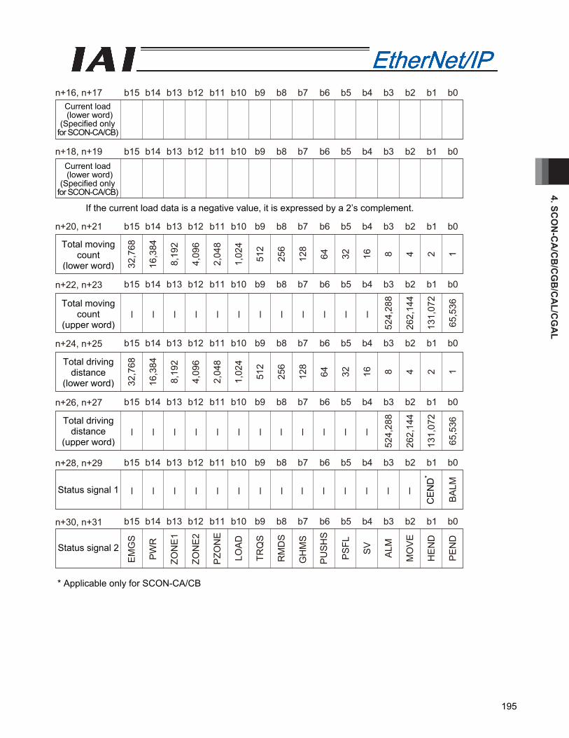
4. SCO
N-C
A/C
B/C
GB
/CA
L/CG
AL
195
b15n+18, n+19 b14 b13 b12 b11 b10 b9 b8 b7 b6 b5 b4 b3 b2 b1 b0
32,7
68
16,3
84
8,19
2
4,09
6
2,04
8
1,02
4
512
256
128
64
32
16
8 4 2 1
b15 b14 b13 b12 b11 b10 b9 b8 b7 b6 b5 b4 b3 b2 b1 b0
b15n+20, n+21 b14 b13 b12 b11 b10 b9 b8 b7 b6 b5 b4 b3 b2 b1 b0
─
─
─
─
─
─
─
─
─
─
─
─
524,
288
262,
144
131,
072
65,5
36
b15
n+22, n+23
b14 b13 b12 b11 b10 b9 b8 b7 b6 b5 b4 b3 b2 b1 b0
32,7
68
16,3
84
8,19
2
4,09
6
2,04
8
1,02
4
512
256
128
64
32
16
8 4 2 1
b15
n+24, n+25
b14 b13 b12 b11 b10 b9 b8 b7 b6 b5 b4 b3 b2 b1 b0
─
─
─
─
─
─
─
─
─
─
─
─
524,
288
262,
144
131,
072
65,5
36
n+26, n+27
─
─
─
─
─
─
─
─
─
─
─
─
─
─
b15 b14 b13 b12 b11 b10 b9 b8 b7 b6 b5 b4 b3 b2 b1 b0
EM
GS
PW
R
ZON
E1
ZON
E2
PZO
NE
LOA
D
TRQ
S
RM
DS
GH
MS
PU
SH
S
PS
FL
SV
ALM
MO
VE
HE
ND
PE
ND
CE
ND
BA
LM
b15
n+28, n+29
n+30, n+31 b14 b13 b12 b11 b10 b9 b8 b7 b6 b5 b4 b3 b2 b1 b0
b15n+16, n+17 b14 b13 b12 b11 b10 b9 b8 b7 b6 b5 b4 b3 b2 b1 b0
If the current load data is a negative value, it is expressed by a 2’s complement. * Applicable only for SCON-CA/CB
Status signal 1
Status signal 2
Current load (lower word)
(Specified only for SCON-CA/CB)
Current load (lower word)
(Specified only for SCON-CA/CB)
Total moving count
(lower word)
Total moving count
(upper word)
Total driving distance
(lower word)
Total driving distance
(upper word) C
EN
D*
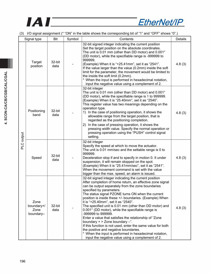
4. S
CO
N-C
A/C
B/C
GB
/CA
L/C
GA
L
196
(3) I/O signal assignment (* “ON” in the table shows the corresponding bit of “1” and “OFF” shows “0”.)
Signal type Bit Symbol Contents Details
Target position
32-bit data -
32-bit signed integer indicating the current position Set the target position on the absolute coordinates. The unit is 0.01 mm (other than DD motor) and 0.001° (DD motor), while the specifiable range is -999999 to 999999. (Example) When it is “+25.41mm”, set it as “2541”. If the value larger than the value (0.2mm) inside the soft limit for the parameter, the movement would be limited to the inside the soft limit (0.2mm). * When the input is performed in hexadecimal notation,
input the negative value using a complement of 2.
4.8 (3)
Positioning band
32-bit data -
32-bit integer The unit is 0.01 mm (other than DD motor) and 0.001° (DD motor), while the specifiable range is 1 to 999999. (Example) When it is “25.40mm”, set it as “2540”. This register value has two meanings depending on the operation type. 1) In the case of positioning operation, it shows the
allowable range from the target position, that is regarded as the positioning completion.
2) In the case of pressing operation, it shows the pressing width value. Specify the normal operation or pressing operation using the “PUSH” control signal setting.
4.8 (3)
Speed 32-bit data -
32-bit integer Specify the speed at which to move the actuator. The unit is 0.01 mm/sec and the settable range is 0 to 999999. Deceleration stop if and to specify in motion 0. It under suspension, it will remain stopped on the spot. (Example) When it is “25.41mm/sec”, set it as “2541”. When the movement command is set with the value bigger than the max. speed, an alarm is issued.
4.8 (3)
PLC
out
put
Zone boundary+/
Zone boundary–
32-bit data -
32-bit signed integer indicating the current position After completion of home return, an effective zone signal can be output separately from the zone boundaries specified by parameters. The status signal PZONE turns ON when the current position is inside these +/- boundaries. (Example) When it is “+25.40mm”, set it as “2540”. The specified unit is 0.01 mm (other than DD motor) and 0.001° (DD motor), while the specifiable range is -999999 to 999999. Enter a value that satisfies the relationship of “Zone boundary + > Zone boundary –”. If this function is not used, enter the same value for both the positive and negative boundaries. * When the input is performed in hexadecimal notation,
input the negative value using a complement of 2.
4.8 (3)
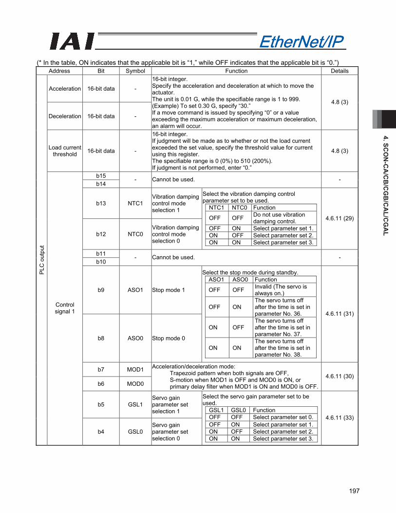
4. SCO
N-C
A/C
B/C
GB
/CA
L/CG
AL
197
(* In the table, ON indicates that the applicable bit is “1,” while OFF indicates that the applicable bit is “0.”)
Address Bit Symbol Function Details
Acceleration 16-bit data -
Deceleration 16-bit data -
16-bit integer. Specify the acceleration and deceleration at which to move the actuator. The unit is 0.01 G, while the specifiable range is 1 to 999. (Example) To set 0.30 G, specify “30.” If a move command is issued by specifying “0” or a value exceeding the maximum acceleration or maximum deceleration, an alarm will occur.
4.8 (3)
Load current threshold 16-bit data -
16-bit integer. If judgment will be made as to whether or not the load current exceeded the set value, specify the threshold value for current using this register. The specifiable range is 0 (0%) to 510 (200%). If judgment is not performed, enter “0.”
4.8 (3)
b15 b14
- Cannot be used. -
b13 NTC1 Vibration damping control mode selection 1
b12 NTC0 Vibration damping control mode selection 0
Select the vibration damping control parameter set to be used.
NTC1 NTC0 Function
OFF OFF Do not use vibration damping control.
OFF ON Select parameter set 1. ON OFF Select parameter set 2. ON ON Select parameter set 3.
4.6.11 (29)
b11 b10
- Cannot be used. -
b9 ASO1 Stop mode 1
b8 ASO0 Stop mode 0
Select the stop mode during standby. ASO1 ASO0 Function
OFF OFF Invalid (The servo is always on.)
OFF ON The servo turns off after the time is set in parameter No. 36.
ON OFF The servo turns off after the time is set in parameter No. 37.
ON ON The servo turns off after the time is set in parameter No. 38.
4.6.11 (31)
b7 MOD1
b6 MOD0
Acceleration/deceleration mode: Trapezoid pattern when both signals are OFF, S-motion when MOD1 is OFF and MOD0 is ON, or primary delay filter when MOD1 is ON and MOD0 is OFF.
4.6.11 (30)
b5 GSL1 Servo gain parameter set selection 1
PLC
out
put
Control signal 1
b4 GSL0 Servo gain parameter set selection 0
Select the servo gain parameter set to be used.
GSL1 GSL0 Function OFF OFF Select parameter set 0. OFF ON Select parameter set 1. ON OFF Select parameter set 2. ON ON Select parameter set 3.
4.6.11 (33)
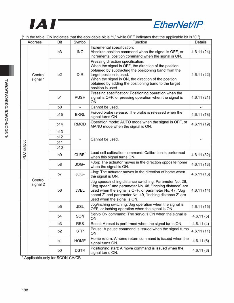
4. S
CO
N-C
A/C
B/C
GB
/CA
L/C
GA
L
198
(* In the table, ON indicates that the applicable bit is “1,” while OFF indicates that the applicable bit is “0.”)
Address Bit Symbol Function Details
b3 INC Incremental specification: Absolute position command when the signal is OFF, or incremental position command when the signal is ON.
4.6.11 (24)
b2 DIR
Pressing direction specification: When the signal is OFF, the direction of the position obtained by subtracting the positioning band from the target position is used. When the signal is ON, the direction of the position obtained by adding the positioning band to the target position is used.
4.6.11 (22)
b1 PUSH Pressing specification: Positioning operation when the signal is OFF, or pressing operation when the signal is ON.
4.6.11 (21)
Control signal 1
b0 - Cannot be used. -
b15 BKRL Forced brake release: The brake is released when the signal turns ON. 4.6.11 (18)
b14 RMOD Operation mode: AUTO mode when the signal is OFF, or MANU mode when the signal is ON. 4.6.11 (19)
b13 b12 b11 b10
- Cannot be used. -
b9 CLBR* Load cell calibration command: Calibration is performed when this signal turns ON. 4.6.11 (32)
b8 JOG+ +Jog: The actuator moves in the direction opposite home when the signal is ON. 4.6.11 (13)
b7 JOG- -Jog: The actuator moves in the direction of home when the signal is ON. 4.6.11 (13)
b6 JVEL
Jog speed/inching distance switching: Parameter No. 26, “Jog speed” and parameter No. 48, “Inching distance” are used when the signal is OFF, or parameter No. 47, “Jog speed 2” and parameter No. 49, “Inching distance 2” are used when the signal is ON.
4.6.11 (14)
b5 JISL Jog/inching switching: Jog operation when the signal is OFF, or inching operation when the signal is ON. 4.6.11 (15)
b4 SON Servo ON command: The servo is ON when the signal is ON. 4.6.11 (5)
b3 RES Reset: A reset is performed when the signal turns ON. 4.6.11 (4)
b2 STP Pause: A pause command is issued when the signal turns ON. 4.6.11 (11)
b1 HOME Home return: A home return command is issued when the signal turns ON. 4.6.11 (6)
PLC
out
put
Control signal 2
b0 DSTR Positioning start: A move command is issued when the signal turns ON. 4.6.11 (8)
* Applicable only for SCON-CA/CB

4. SCO
N-C
A/C
B/C
GB
/CA
L/CG
AL
199
(* In the table, ON indicates that the applicable bit is “1,” while OFF indicates that the applicable bit is “0.”)
Signal type Bit Symbol Description Details
Current position 32 bit data -
32-bit signed integer indicating the current position. The unit is 0.01 mm (other than DD motor) and 0.001° (DD motor). (Example) Reading: 000003FFH = 1023 (decimal)
= 10.23 mm * If this data is read as a hexadecimal, a negative value
is indicated by a complement of 2.
4.8 (3)
Command current 32-bit data -
32-bit integer. The value of electrical current specified by the present command is indicated. The unit is mA. (Example) Reading: 000003FFH = 1023 (decimal)
= 1023 mA
4.8 (3)
Current speed 32-bit data -
32-bit signed integer. The current speed is indicated. Positive value: The actuator is moving in the direction opposite home. Negative value: The actuator is moving in the direction of home. The unit is 0.01 mm/sec. (Example) Reading: 000003FFH = 1023 (decimal)
= 10.23 mm/sec * If this data is read as a hexadecimal value, a negative
value is indicated by a compliment of 2.
4.8 (3)
Alarm code 16-bit data -
16-bit integer. If an alarm occurs, an alarm code will be output. 0 is output when no alarm is present. For details on alarms, refer to the operation manual for the controller.
4.8 (3)
Current load (Specified only
for SCON -CA/CB function)
32-bit data -
32-bit signed integer. The unit is 0.01 N. * If this data is read as a hexadecimal, a negative value
is indicated by a compliment of 2. 4.8 (3)
Total moving count 32-bit data - 32-bit integer.
The unit is times. -
Total moving distance 32-bit data - 32-bit integer.
The unit is m. -
b15 b14 b13 b12 b11 b10 b9 b8 b7 b6 b5 b4 b3 b2
- Cannot be used. -
b1 CEND* Load cell calibration is complete: This signal turns ON when calibration is complete. 4.6.11 (32)
PLC
inpu
t
Status signal 1
b0 BALM Absolute battery voltage low warning: This signal turns ON when the voltage drops. 4.6.11 (28)
* Applicable only for SCON-CA/CB

4. S
CO
N-C
A/C
B/C
GB
/CA
L/C
GA
L
200
(* In the table, ON indicates that the applicable bit is “1,” while OFF indicates that the applicable bit is “0.”)
Signal type Bit Symbol Description Details
b15 EMGS Emergency stop: An emergency stop is being executed when the signal is ON. 4.6.11 (2)
b14 PWR Controller ready: The signal turns ON when the controller becomes ready. 4.6.11 (1)
b13 ZONE2 Zone 2: The signal is ON when the current position is inside the specified zone. 4.6.11 (12)
b12 ZONE1 Zone 1: The signal is ON when the current position is inside the specified zone. 4.6.11 (12)
b11 PZONE Position zone: The signal is ON when the current position is inside the specified position zone. 4.6.11 (12)
b10 LOAD Load output judgment: Reached when the signal is ON, or not yet reached when the signal is OFF. (For details, refer to the operation manual for the controller.)
4.6.11 (26)
b9 TRQS Torque level: Reached when the signal is ON, or not yet reached when the signal is OFF. (For details, refer to the operation manual for the controller.)
4.6.11 (27)
b8 RMDS Operation mode: The signal is OFF when the current mode AUTO, or ON when the current mode is MANU. 4.6.11 (19)
b7 GHMS Home return in progress: The signal is ON while the home return is in progress. 4.6.11 (6)
b6 PUSHS Pressing operation in progress: The signal is ON while the pressing operation is in progress. 4.6.11 (25)
b5 PSFL Missed work part during pressing operation: The signal turns ON when the actuator missed the work part during pressing operation.
4.6.11 (23)
b4 SV Ready: The signal is ON when the servo is ON. 4.6.11 (5)b3 ALM Alarm: The signal turns ON when an alarm occurs. 4.6.11 (3)
b2 MOVE Moving signal: The signal is ON while the actuator is moving. 4.6.11 (9)
b1 HEND Home return complete: The signal turns ON when the home return is completed. 4.6.11 (6)
PLC
inpu
t
Status signal 2
b0 PEND Positioning complete signal: The signal turns ON when the positioning is completed. 4.6.11 (10)
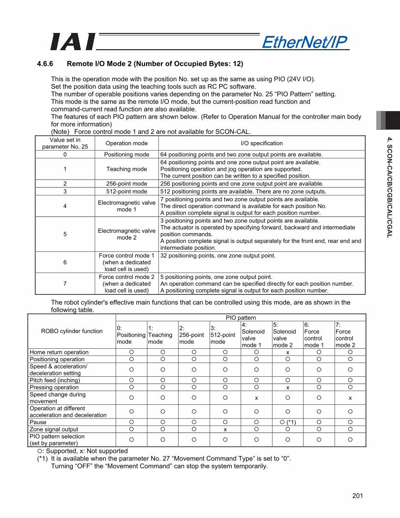
4. SCO
N-C
A/C
B/C
GB
/CA
L/CG
AL
201
4.6.6 Remote I/O Mode 2 (Number of Occupied Bytes: 12)
This is the operation mode with the position No. set up as the same as using PIO (24V I/O). Set the position data using the teaching tools such as RC PC software. The number of operable positions varies depending on the parameter No. 25 “PIO Pattern” setting. This mode is the same as the remote I/O mode, but the current-position read function and command-current read function are also available. The features of each PIO pattern are shown below. (Refer to Operation Manual for the controller main body for more information) (Note) Force control mode 1 and 2 are not available for SCON-CAL. Value set in
parameter No. 25 Operation mode I/O specification
0 Positioning mode 64 positioning points and two zone output points are available.
1 Teaching mode 64 positioning points and one zone output point are available. Positioning operation and jog operation are supported. The current position can be written to a specified position.
2 256-point mode 256 positioning points and one zone output point are available. 3 512-point mode 512 positioning points are available. There are no zone outputs.
4 Electromagnetic valve mode 1
7 positioning points and two zone output points are available. The direct operation command is available for each position No. A position complete signal is output for each position number.
5 Electromagnetic valve mode 2
3 positioning points and two zone output points are available. The actuator is operated by specifying forward, backward and intermediate position commands. A position complete signal is output separately for the front end, rear end and intermediate position.
6 Force control mode 1
(when a dedicated load cell is used)
32 positioning points, one zone output point.
7 Force control mode 2
(when a dedicated load cell is used)
5 positioning points, one zone output point. An operation command can be specified directly for each position number. A positioning complete signal is output for each position number.
The robot cylinder's effective main functions that can be controlled using this mode, are as shown in the following table.
PIO pattern
ROBO cylinder function 0: Positioning mode
1: Teaching mode
2: 256-point mode
3: 512-point mode
4: Solenoid valve mode 1
5: Solenoid valve mode 2
6: Force control mode 1
7: Force control mode 2
Home return operation x Positioning operation Speed & acceleration/ deceleration setting
Pitch feed (inching) Pressing operation x Speed change during movement x x
Operation at different acceleration and deceleration
Pause (*1) Zone signal output x PIO pattern selection (set by parameter)
: Supported, x: Not supported (*1) It is available when the parameter No. 27 “Movement Command Type” is set to “0”.
Turning “OFF” the “Movement Command” can stop the system temporarily.

4. S
CO
N-C
A/C
B/C
GB
/CA
L/C
GA
L
202
(1) PLC address configuration (* “n” indicates the node address of each axis.)
Parameter No. 84
SCON-CA/CB/CAL side DI and input
register
PLC side output address (bytes)
SCON-CA/CB/CAL side DO and output
register
PLC side input address (bytes)
Port number 0 to 15 n+0, n+1 Port number 0 to 15 n+0, n+1 n+2, n+3 Occupied area n+2, n+3 n+4, n+5 n+4, n+5 n+6, n+7 Current position n+6, n+7 n+8, n+9 n+8, n+9
4 Occupied area
n+10, n+11 Command current n+10, n+11 (Note) The areas denoted by Occupied area cannot be used for any other purpose.
Also, exercise caution to avoid node address duplication. (2) I/O Signal Allocation for each Axis
The I/O signals of each axis consist of one input word (6 words = 12 bytes) and one output word in the I/O areas.
The areas controlled by port number are controlled using ON/OFF bit signals. The current position is a 2-word (32-bit) binary data (unit: 0.01 mm (other than DD motor) and 0.001°
(DD motor)). The command current is expressed using 2-word (32 bits) binary data (Unit: 1mA).
PLC output Address (* “n” indicates the node address of each axis.)
1 word = 2 bytes =16 bits
Controller input port number
n+0、n+1n+0, n+1
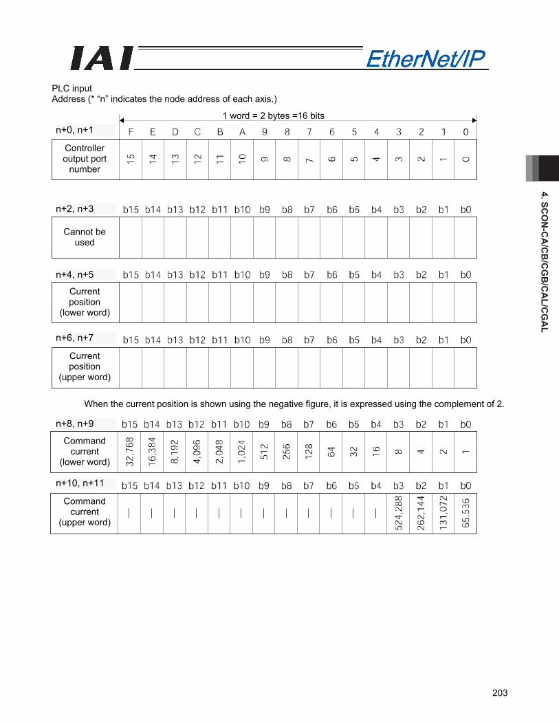
4. SCO
N-C
A/C
B/C
GB
/CA
L/CG
AL
203
PLC input Address (* “n” indicates the node address of each axis.)
When the current position is shown using the negative figure, it is expressed using the complement of 2.
Command current
(lower word)
Command current
(upper word)
n+8、n+9
n+10、n+11n+10, n+11
n+8, n+9
Controller output port
number
Cannot be used
Current position
(lower word)
Current position
(upper word)
1 word = 2 bytes =16 bits n+0、n+1
n+2、n+3
n+4、n+5
n+6、n+7n+6, n+7
n+4, n+5
n+2, n+3
n+0, n+1
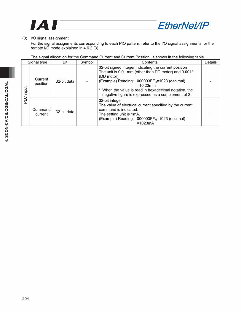
4. S
CO
N-C
A/C
B/C
GB
/CA
L/C
GA
L
204
(3) I/O signal assignment
For the signal assignments corresponding to each PIO pattern, refer to the I/O signal assignments for the remote I/O mode explained in 4.6.2 (3).
The signal allocation for the Command Current and Current Position, is shown in the following table.
Signal type Bit Symbol Contents Details
Current position 32-bit data -
32-bit signed integer indicating the current position The unit is 0.01 mm (other than DD motor) and 0.001° (DD motor). (Example) Reading: 000003FFH=1023 (decimal)
=10.23mm * When the value is read in hexadecimal notation, the
negative figure is expressed as a complement of 2.
-
PLC
inpu
t
Command current 32-bit data -
32-bit integer The value of electrical current specified by the current command is indicated. The setting unit is 1mA. (Example) Reading: 000003FFH=1023 (decimal)
=1023mA
-
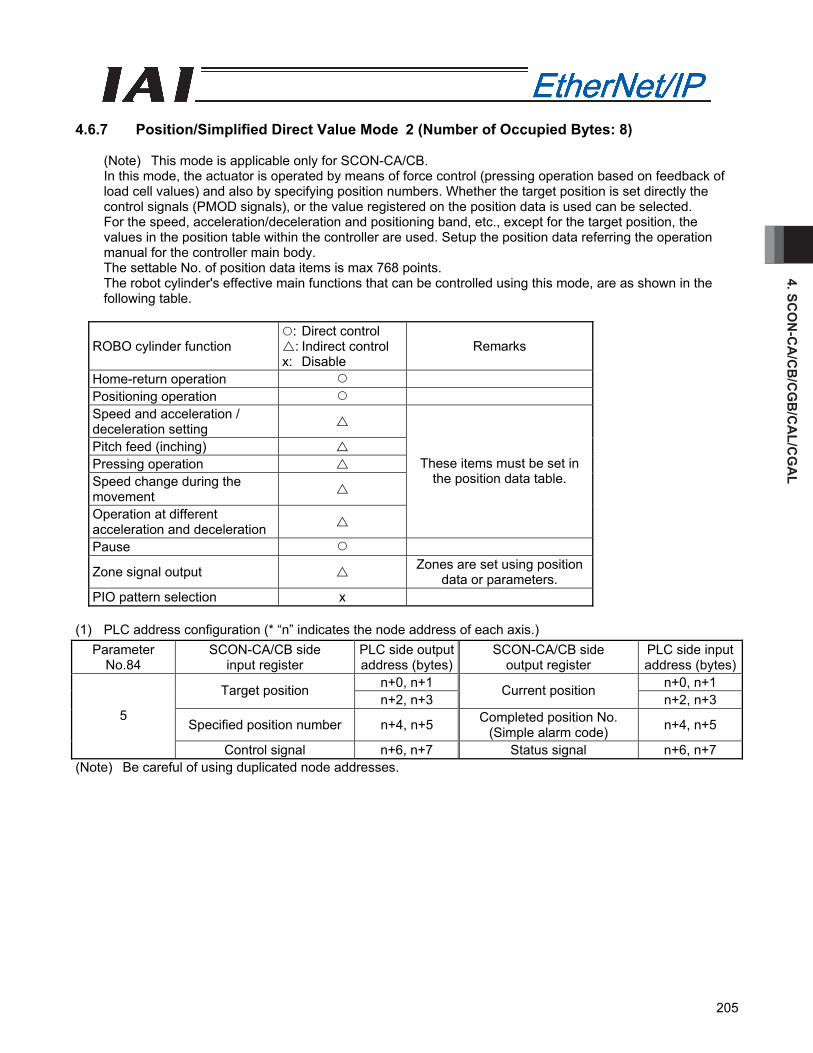
4. SCO
N-C
A/C
B/C
GB
/CA
L/CG
AL
205
4.6.7 Position/Simplified Direct Value Mode 2 (Number of Occupied Bytes: 8)
(Note) This mode is applicable only for SCON-CA/CB. In this mode, the actuator is operated by means of force control (pressing operation based on feedback of load cell values) and also by specifying position numbers. Whether the target position is set directly the control signals (PMOD signals), or the value registered on the position data is used can be selected. For the speed, acceleration/deceleration and positioning band, etc., except for the target position, the values in the position table within the controller are used. Setup the position data referring the operation manual for the controller main body. The settable No. of position data items is max 768 points. The robot cylinder's effective main functions that can be controlled using this mode, are as shown in the following table.
ROBO cylinder function : Direct control : Indirect control
x: Disable Remarks
Home-return operation Positioning operation Speed and acceleration / deceleration setting
Pitch feed (inching) Pressing operation Speed change during the movement
Operation at different acceleration and deceleration
These items must be set in the position data table.
Pause
Zone signal output Zones are set using position data or parameters.
PIO pattern selection x (1) PLC address configuration (* “n” indicates the node address of each axis.)
Parameter No.84
SCON-CA/CB side input register
PLC side output address (bytes)
SCON-CA/CB side output register
PLC side input address (bytes)
n+0, n+1 n+0, n+1 Target position n+2, n+3
Current position n+2, n+3
Specified position number n+4, n+5 Completed position No. (Simple alarm code) n+4, n+5
5
Control signal n+6, n+7 Status signal n+6, n+7 (Note) Be careful of using duplicated node addresses.
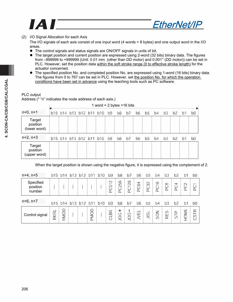
4. S
CO
N-C
A/C
B/C
GB
/CA
L/C
GA
L
206
(2) I/O Signal Allocation for each Axis
The I/O signals of each axis consist of one input word (4 words = 8 bytes) and one output word in the I/O areas.
The control signals and status signals are ON/OFF signals in units of bit. The target position and current position are expressed using 2-word (32 bits) binary data. The figures
from –999999 to +999999 (Unit: 0.01 mm (other than DD motor) and 0.001° (DD motor)) can be set in PLC. However, set the position data within the soft stroke range (0 to effective stroke length) for the actuator concerned.
The specified position No. and completed position No. are expressed using 1-word (16 bits) binary data. The figures from 0 to 767 can be set in PLC. However, set the position No. for which the operation conditions have been set in advance using the teaching tools such as PC software.
PLC output Address (* “n” indicates the node address of each axis.)
When the target position is shown using the negative figure, it is expressed using the complement of 2.
Specified position number
Control signal
n+4、n+5
n+6、n+7n+6, n+7
n+4, n+5
Target position
(lower word)
Target position
(upper word)
1 word = 2 bytes =16 bits
n+0、n+1
n+2、n+3n+2, n+3
n+0, n+1

4. SCO
N-C
A/C
B/C
GB
/CA
L/CG
AL
207
PLC input Address (* “n” indicates the node address of each axis.)
When the current position is shown using the negative figure, it is expressed using the complement of 2.
b15 b14 b13 b12 b11 b10 b9 b8 b7 b6 b5 b4 b3 b2 b1 b0
Completed position number
―
―
―
―
―
―
PM
512
PM
256
PM
128
PM
64
PM
32
PM
16
PM
8
PM
4
PM
2
PM
1
b15 b14 b13 b12 b11 b10 b9 b8 b7 b6 b5 b4 b3 b2 b1 b0
Status signal
EM
GS
PW
R
CEN
D
ZON
E1
PZO
NE
/ ZO
NE2
LOA
D
TRQ
S
RM
DS
BA
LM
PUSH
S
PS
FL
SV
ALM
MO
VE
HEN
D
PEN
D
Current position
(lower word)
Current position
(upper word)
1 word = 2 bytes =16 bits
n+0、n+1
n+2、n+3n+2, n+3
n+0, n+1
n+4, n+5
n+6, n+7

4. S
CO
N-C
A/C
B/C
GB
/CA
L/C
GA
L
208
(3) I/O signal assignments (* In the table, ON indicates that the applicable bit is “1,” while OFF indicates that
the applicable bit is “0.”) Signal type Bit Symbol Description Details
Target position 32-bit data -
32-bit signed integer. Specify the target position on the absolute coordinates. The unit is 0.01 mm (other than DD motor) and 0.001° (DD motor), while the specifiable range is -999999 to 999999. (Example) To set +25.40 mm, specify “2540.” If the entered value exceeds the range of soft limit parameters (within 0.2 mm inside of the parameter values), the movement will be limited to within the range of soft limits (within 0.2 mm inside of the parameter values). * If this data is entered using a hexadecimal, enter a
negative value as a compliment of 2.
4.8 (1)
Specified position number
16-bit data
PC1 to PC512
16-bit integer. To operate the actuator, position data is needed for which operation conditions have already been entered using the teaching tools such as PC. Use this register to specify the position number for which data has been entered. The specifiable range is 0 to 767. If an out-of-range value is specified or the specified position number is not yet set, an alarm will occur when the start signal is turned ON.
4.8 (1)
b15 BKRL Forced brake release: The brake is released when the signal turns ON. 4.6.11 (18)
b14 RMOD Operation mode: AUTO mode when the signal is OFF, or MANU mode when the signal is ON. 4.6.11 (19)
b13 b12
- Cannot be used. -
b11 PMOD Position/simple direct switching: Position mode when the signal is OFF, or simple direct mode when the signal is ON. 4.6.11 (20)
b10 - Cannot be used. -
b9 CLBR Load cell calibration command: Calibration is performed when this signal turns ON. 4.6.11 (32)
b8 JOG+ +Jog: The actuator moves in the direction opposite home when the signal is ON. 4.6.11 (13)
b7 JOG- -Jog: The actuator moves in the direction of home when the signal is ON. 4.6.11 (13)
b6 JVEL
Jog speed/inching distance switching: Parameter No. 26, “Jog speed” and parameter No. 48, “Inching distance” are used when the signal is OFF, or parameter No. 47, “Jog speed 2” and parameter No. 49, “Inching distance 2” are used when the signal is ON.
4.6.11 (14)
b5 JISL Jog/inching switching: Jog operation when the signal is OFF, or inching operation when the signal is ON. 4.6.11 (15)
b4 SON Servo ON command: The servo is ON when the signal is ON. 4.6.11 (5)b3 RES Reset: A reset is performed when the signal turns ON. 4.6.11 (4)b2 STP Pause: A pause command is issued when the signal turns ON. 4.6.11 (11)
b1 HOME Home return: A home return command is issued when the signal turns ON. 4.6.11 (6)
PLC
out
put
Control signal
b0 CSTR Positioning start: A move command is issued when the signal turns ON. 4.6.11 (7)
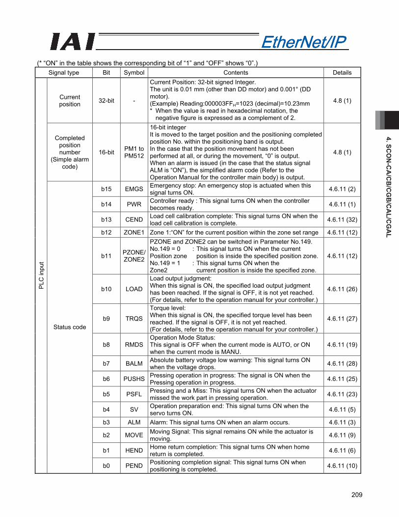
4. SCO
N-C
A/C
B/C
GB
/CA
L/CG
AL
209
(* “ON” in the table shows the corresponding bit of “1” and “OFF” shows “0”.)
Signal type Bit Symbol Contents Details
Current position 32-bit -
Current Position: 32-bit signed Integer. The unit is 0.01 mm (other than DD motor) and 0.001° (DD motor). (Example) Reading:000003FFH=1023 (decimal)=10.23mm * When the value is read in hexadecimal notation, the
negative figure is expressed as a complement of 2.
4.8 (1)
Completed position number
(Simple alarm code)
16-bit PM1 to PM512
16-bit integer It is moved to the target position and the positioning completed position No. within the positioning band is output. In the case that the position movement has not been performed at all, or during the movement, “0” is output. When an alarm is issued (in the case that the status signal ALM is “ON”), the simplified alarm code (Refer to the Operation Manual for the controller main body) is output.
4.8 (1)
b15 EMGS Emergency stop: An emergency stop is actuated when this signal turns ON. 4.6.11 (2)
b14 PWR Controller ready : This signal turns ON when the controller becomes ready. 4.6.11 (1)
b13 CEND Load cell calibration complete: This signal turns ON when the load cell calibration is complete. 4.6.11 (32)
b12 ZONE1 Zone 1:“ON” for the current position within the zone set range 4.6.11 (12)
b11 PZONE/ ZONE2
PZONE and ZONE2 can be switched in Parameter No.149. No.149 = 0 : This signal turns ON when the current Position zone position is inside the specified position zone. No.149 = 1 : This signal turns ON when the Zone2 current position is inside the specified zone.
4.6.11 (12)
b10 LOAD
Load output judgment: When this signal is ON, the specified load output judgment has been reached. If the signal is OFF, it is not yet reached. (For details, refer to the operation manual for your controller.)
4.6.11 (26)
b9 TRQS
Torque level: When this signal is ON, the specified torque level has been reached. If the signal is OFF, it is not yet reached. (For details, refer to the operation manual for your controller.)
4.6.11 (27)
b8 RMDS Operation Mode Status: This signal is OFF when the current mode is AUTO, or ON when the current mode is MANU.
4.6.11 (19)
b7 BALM Absolute battery voltage low warning: This signal turns ON when the voltage drops. 4.6.11 (28)
b6 PUSHS Pressing operation in progress: The signal is ON when the Pressing operation in progress. 4.6.11 (25)
b5 PSFL Pressing and a Miss: This signal turns ON when the actuator missed the work part in pressing operation. 4.6.11 (23)
b4 SV Operation preparation end: This signal turns ON when the servo turns ON. 4.6.11 (5)
b3 ALM Alarm: This signal turns ON when an alarm occurs. 4.6.11 (3)
b2 MOVE Moving Signal: This signal remains ON while the actuator is moving. 4.6.11 (9)
b1 HEND Home return completion: This signal turns ON when home return is completed. 4.6.11 (6)
PLC
inpu
t
Status code
b0 PEND Positioning completion signal: This signal turns ON when positioning is completed. 4.6.11 (10)
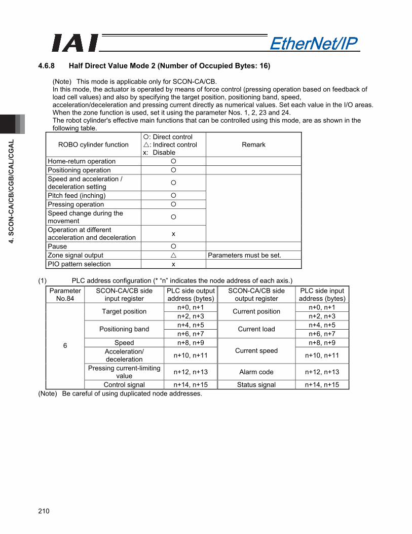
4. S
CO
N-C
A/C
B/C
GB
/CA
L/C
GA
L
210
4.6.8 Half Direct Value Mode 2 (Number of Occupied Bytes: 16)
(Note) This mode is applicable only for SCON-CA/CB. In this mode, the actuator is operated by means of force control (pressing operation based on feedback of load cell values) and also by specifying the target position, positioning band, speed, acceleration/deceleration and pressing current directly as numerical values. Set each value in the I/O areas. When the zone function is used, set it using the parameter Nos. 1, 2, 23 and 24. The robot cylinder's effective main functions that can be controlled using this mode, are as shown in the following table.
ROBO cylinder function : Direct control : Indirect control
x: Disable Remark
Home-return operation Positioning operation Speed and acceleration / deceleration setting
Pitch feed (inching) Pressing operation Speed change during the movement
Operation at different acceleration and deceleration x
Pause Zone signal output Parameters must be set. PIO pattern selection x
(1) PLC address configuration (* “n” indicates the node address of each axis.)
ParameterNo.84
SCON-CA/CB side input register
PLC side output address (bytes)
SCON-CA/CB side output register
PLC side input address (bytes)
n+0, n+1 n+0, n+1 Target position n+2, n+3
Current position n+2, n+3
n+4, n+5 n+4, n+5 Positioning band n+6, n+7
Current load n+6, n+7
Speed n+8, n+9 n+8, n+9 Acceleration/ deceleration n+10, n+11
Current speed n+10, n+11
Pressing current-limiting value n+12, n+13 Alarm code n+12, n+13
6
Control signal n+14, n+15 Status signal n+14, n+15 (Note) Be careful of using duplicated node addresses.

4. SCO
N-C
A/C
B/C
GB
/CA
L/CG
AL
211
(2) I/O Signal Allocation for each Axis
The I/O signals of each axis consist of one input word (8 words = 16 bytes) and one output word in the I/O areas.
The control signals and status signals are ON/OFF signals in units of bit. The target position and current position are expressed using 2-word (32 bits) binary data. The figures
from –999999 to +999999 (Unit: 0.01 mm (other than DD motor) and 0.001° (DD motor)) can be set in PLC. However, set the position data within the soft stroke range (0 to effective stroke length) for the actuator concerned.
Set the positioning band. The positioning band is expressed using 2-word (32 bits) binary data. The figures from 1 to +999999 (Unit: 0.01 mm (other than DD motor) and 0.001° (DD motor)) can be set in PLC.
The speed is a 1-word (16-bit) binary data. Although values from 0 to +65535 (unit: 1.0 mm/sec or 0.1 mm/sec) can be handled by the PLC, set a value not exceeding the maximum speed of the applicable actuator. Parameter No. 159, FB Half Direct Mode Speed Unit, determines the unit of measure.
Parameter No.159 setting value Speed setting unit0 1.0 mm/sec 1 0.1 mm/sec
The Acceleration/Deceleration is expressed using 1-word (16 bits) binary data. The figures from 1 to 999
(Unit: 0.01G) can be set in PLC. However, set the value that does not exceed the max. acceleration/deceleration value for the actuator in question.
The pressing current-limiting value is expressed using 1-word (16 bits) binary data. The figures from 0 (0%) to 510 (200%) can be set in PLC. However, set the value within the settable range for the pressing current-limiting value (Refer to the Catalog or Operation Manual for the actuator) for the actuator concerned.
Set Value Pressing current-limiting value
The current load is 2-word (32-bit) binary data (unit: 0.01 N). The current speed is expressed using 2-word (32 bits) binary data (Unit: 0.01mm/sec). The alarm code is expressed using 1-word (16 bits) binary data.
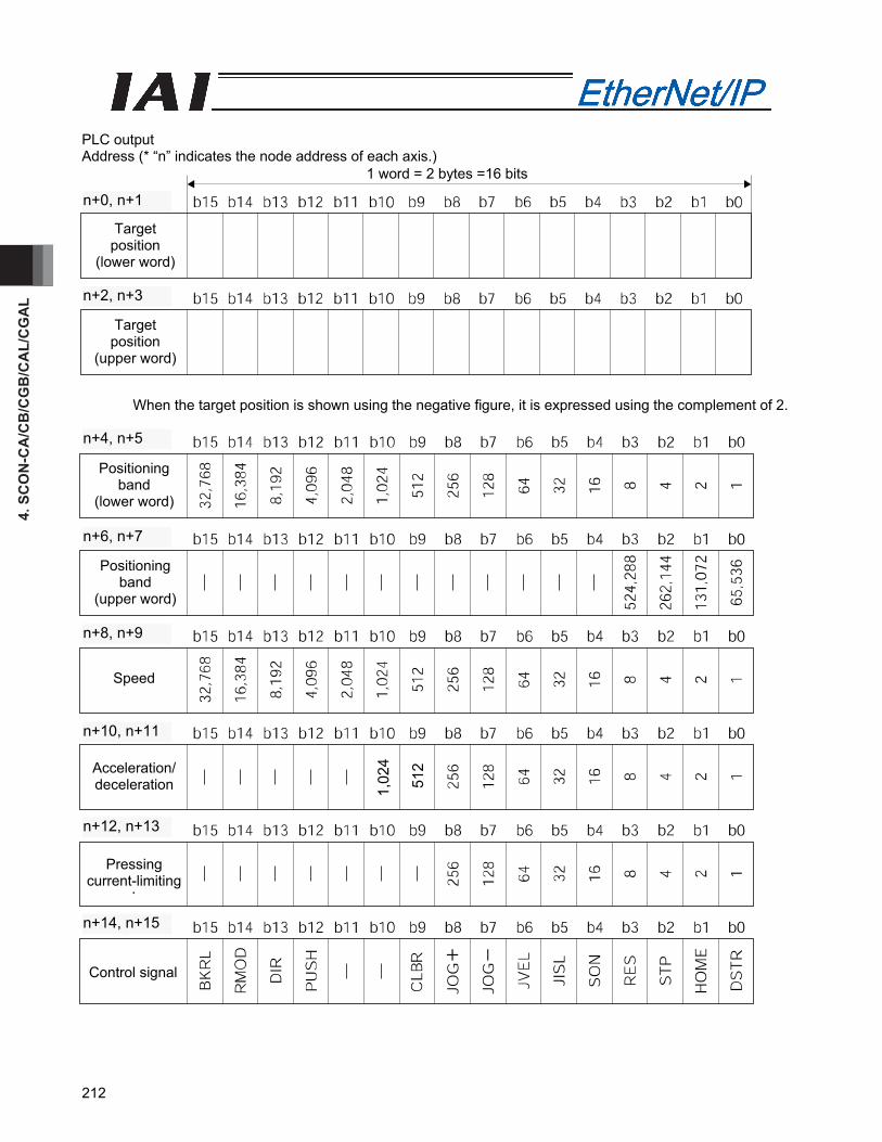
4. S
CO
N-C
A/C
B/C
GB
/CA
L/C
GA
L
212
PLC output Address (* “n” indicates the node address of each axis.)
When the target position is shown using the negative figure, it is expressed using the complement of 2.
Target position
(lower word)
Target position
(upper word)
1 word = 2 bytes =16 bits
n+0、n+1
n+2、n+3n+2, n+3
n+0, n+1
Positioning band
(lower word)
Positioning band
(upper word)
Speed
Acceleration/ deceleration
Pressing current-limiting
l
Control signal
n+4、n+5
n+6、n+7
n+8、n+9
n+10、n+11
n+12、n+13
n+14、n+15
n+10, n+11
n+8, n+9
n+6, n+7
n+4, n+5
n+12, n+13
n+14, n+15
1,02
4
512
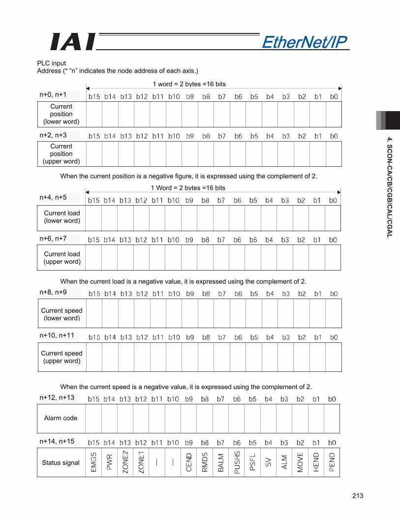
4. SCO
N-C
A/C
B/C
GB
/CA
L/CG
AL
213
PLC input Address (* “n” indicates the node address of each axis.)
When the current position is a negative figure, it is expressed using the complement of 2.
When the current load is a negative value, it is expressed using the complement of 2.
When the current speed is a negative value, it is expressed using the complement of 2.
n+4、n+5
n+6、n+7
Current speed (lower word)
Current speed (upper word)
n+8、n+9
n+10、n+11n+10, n+11
n+8, n+9
1 Word = 2 bytes =16 bits
Current load (lower word)
Current load (upper word)
n+6, n+7
n+4, n+5
1 word = 2 bytes =16 bits
Current position
(lower word)
Current position
(upper word)
n+0、n+1
n+2、n+3n+2, n+3
n+0, n+1
Alarm code
Status signal
n+12、n+13
n+14、n+15
n+12, n+13
n+14, n+15
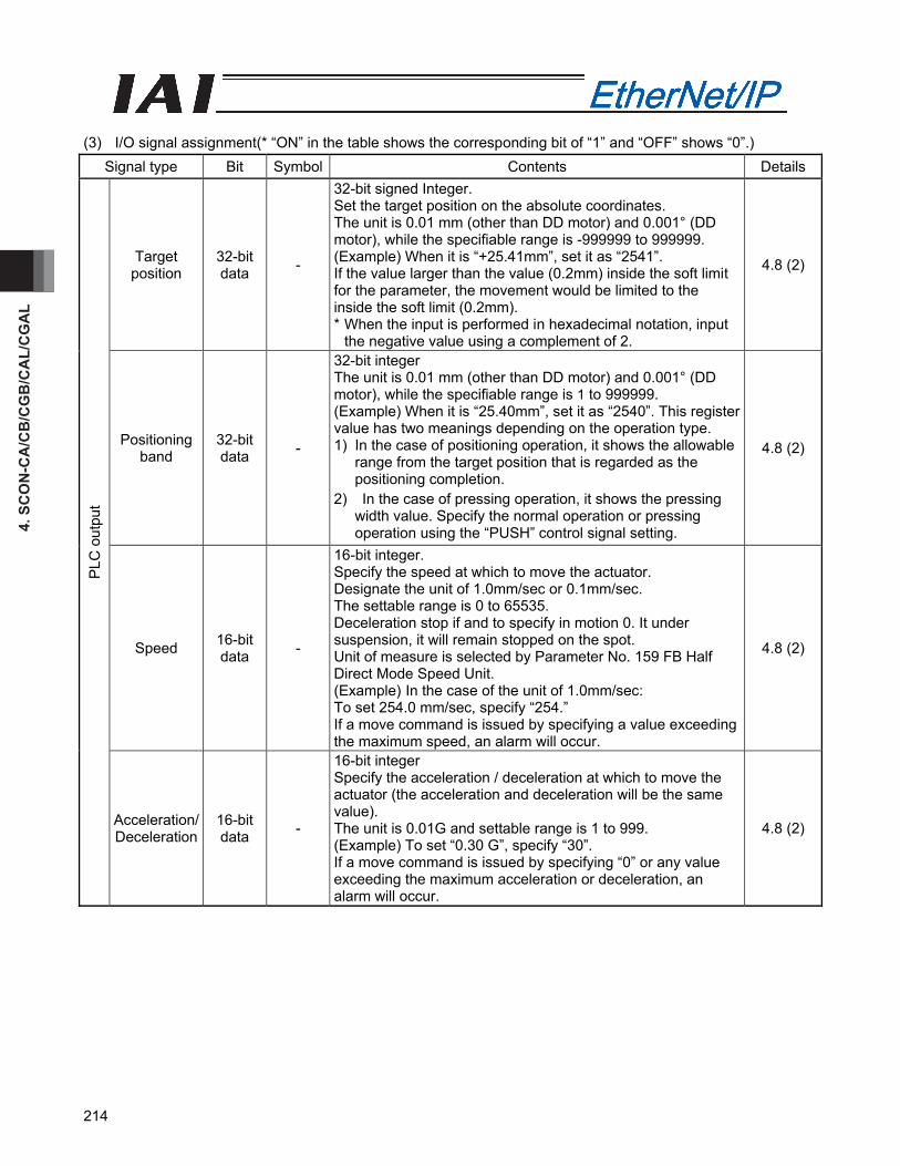
4. S
CO
N-C
A/C
B/C
GB
/CA
L/C
GA
L
214
(3) I/O signal assignment(* “ON” in the table shows the corresponding bit of “1” and “OFF” shows “0”.)
Signal type Bit Symbol Contents Details
Target position
32-bit data -
32-bit signed Integer. Set the target position on the absolute coordinates. The unit is 0.01 mm (other than DD motor) and 0.001° (DD motor), while the specifiable range is -999999 to 999999. (Example) When it is “+25.41mm”, set it as “2541”. If the value larger than the value (0.2mm) inside the soft limit for the parameter, the movement would be limited to the inside the soft limit (0.2mm). * When the input is performed in hexadecimal notation, input
the negative value using a complement of 2.
4.8 (2)
Positioning band
32-bit data -
32-bit integer The unit is 0.01 mm (other than DD motor) and 0.001° (DD motor), while the specifiable range is 1 to 999999. (Example) When it is “25.40mm”, set it as “2540”. This register value has two meanings depending on the operation type. 1) In the case of positioning operation, it shows the allowable
range from the target position that is regarded as the positioning completion.
2) In the case of pressing operation, it shows the pressing width value. Specify the normal operation or pressing operation using the “PUSH” control signal setting.
4.8 (2)
Speed 16-bit data -
16-bit integer. Specify the speed at which to move the actuator. Designate the unit of 1.0mm/sec or 0.1mm/sec. The settable range is 0 to 65535. Deceleration stop if and to specify in motion 0. It under suspension, it will remain stopped on the spot. Unit of measure is selected by Parameter No. 159 FB Half Direct Mode Speed Unit. (Example) In the case of the unit of 1.0mm/sec: To set 254.0 mm/sec, specify “254.” If a move command is issued by specifying a value exceeding the maximum speed, an alarm will occur.
4.8 (2)
PLC
out
put
Acceleration/ Deceleration
16-bit data -
16-bit integer Specify the acceleration / deceleration at which to move the actuator (the acceleration and deceleration will be the same value). The unit is 0.01G and settable range is 1 to 999. (Example) To set “0.30 G”, specify “30”. If a move command is issued by specifying “0” or any value exceeding the maximum acceleration or deceleration, an alarm will occur.
4.8 (2)
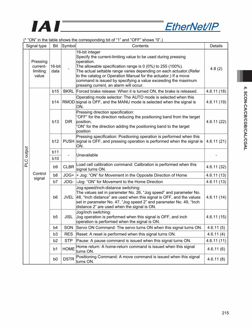
4. SCO
N-C
A/C
B/C
GB
/CA
L/CG
AL
215
(* “ON” in the table shows the corresponding bit of “1” and “OFF” shows “0”.)
Signal type Bit Symbol Contents Details
Pressing current- limiting value
16-bit data -
16-bit integer Specify the current-limiting value to be used during pressing operation. The allowable specification range is 0 (0%) to 255 (100%). The actual settable range varies depending on each actuator.(Refer to the catalog or Operation Manual for the actuator.) If a move command is issued by specifying a value exceeding the maximum pressing current, an alarm will occur.
4.8 (2)
b15 BKRL Forced brake release: When it is turned ON, the brake is released. 4.6.11 (18)
b14 RMOD Operating mode selector: The AUTO mode is selected when this signal is OFF, and the MANU mode is selected when the signal is ON.
4.6.11 (19)
b13 DIR
Pressing direction specification: “OFF” for the direction reducing the positioning band from the target position, “ON” for the direction adding the positioning band to the target position
4.6.11 (22)
b12 PUSH Pressing specification: Positioning operation is performed when this signal is OFF, and pressing operation is performed when the signal is ON.
4.6.11 (21)
b11 b10
- Unavailable -
b9 CLBR Load cell calibration command: Calibration is performed when this signal turns ON. 4.6.11 (32)
b8 JOG+ + Jog: “ON” for Movement in the Opposite Direction of Home 4.6.11 (13)b7 JOG- -Jog: “ON” for Movement to the Home Direction 4.6.11 (13)
b6 JVEL
Jog-speed/inch-distance switching: The values set in parameter No. 26, “Jog speed” and parameter No. 48, “Inch distance” are used when this signal is OFF, and the values set in parameter No. 47, “Jog speed 2” and parameter No. 49, “Inch distance 2” are used when the signal is ON.
4.6.11 (14)
b5 JISL Jog/inch switching: Jog operation is performed when this signal is OFF, and inch operation is performed when the signal is ON.
4.6.11 (15)
b4 SON Servo ON Command: The servo turns ON when this signal turns ON. 4.6.11 (5)b3 RES Reset: A reset is performed when this signal turns ON. 4.6.11 (4)b2 STP Pause: A pause command is issued when this signal turns ON. 4.6.11 (11)
b1 HOME Home return: A home-return command is issued when this signal turns ON. 4.6.11 (6)
PLC
out
put
Control signal
b0 DSTR Positioning Command: A move command is issued when this signal turns ON. 4.6.11 (8)
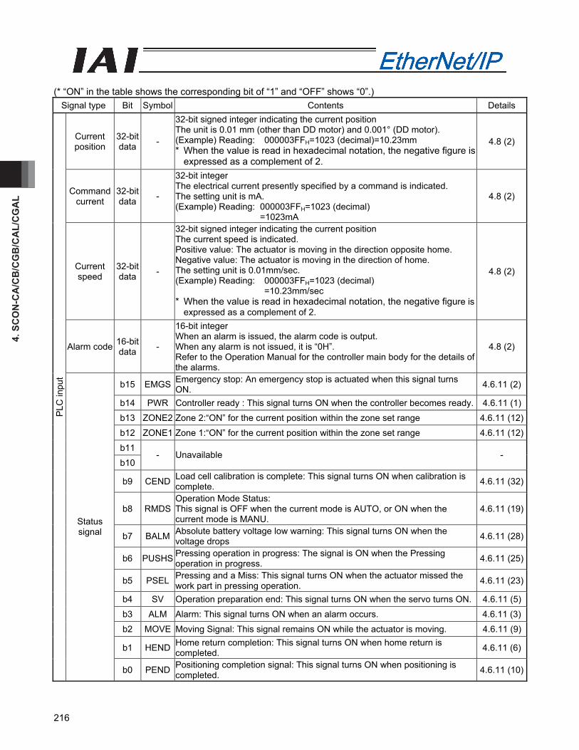
4. S
CO
N-C
A/C
B/C
GB
/CA
L/C
GA
L
216
(* “ON” in the table shows the corresponding bit of “1” and “OFF” shows “0”.)
Signal type Bit Symbol Contents Details
Current position
32-bit data -
32-bit signed integer indicating the current position The unit is 0.01 mm (other than DD motor) and 0.001° (DD motor). (Example) Reading: 000003FFH=1023 (decimal)=10.23mm * When the value is read in hexadecimal notation, the negative figure is
expressed as a complement of 2.
4.8 (2)
Command current
32-bit data -
32-bit integer The electrical current presently specified by a command is indicated. The setting unit is mA. (Example) Reading: 000003FFH=1023 (decimal)
=1023mA
4.8 (2)
Current speed
32-bit data -
32-bit signed integer indicating the current position The current speed is indicated. Positive value: The actuator is moving in the direction opposite home. Negative value: The actuator is moving in the direction of home. The setting unit is 0.01mm/sec. (Example) Reading: 000003FFH=1023 (decimal)
=10.23mm/sec * When the value is read in hexadecimal notation, the negative figure is
expressed as a complement of 2.
4.8 (2)
Alarm code 16-bit data -
16-bit integer When an alarm is issued, the alarm code is output. When any alarm is not issued, it is “0H”. Refer to the Operation Manual for the controller main body for the details of the alarms.
4.8 (2)
b15 EMGS Emergency stop: An emergency stop is actuated when this signal turns ON. 4.6.11 (2)
b14 PWR Controller ready : This signal turns ON when the controller becomes ready. 4.6.11 (1)
b13 ZONE2 Zone 2:“ON” for the current position within the zone set range 4.6.11 (12)
b12 ZONE1 Zone 1:“ON” for the current position within the zone set range 4.6.11 (12)
b11
b10 - Unavailable -
b9 CEND Load cell calibration is complete: This signal turns ON when calibration is complete. 4.6.11 (32)
b8 RMDS Operation Mode Status: This signal is OFF when the current mode is AUTO, or ON when the current mode is MANU.
4.6.11 (19)
b7 BALM Absolute battery voltage low warning: This signal turns ON when the voltage drops 4.6.11 (28)
b6 PUSHS Pressing operation in progress: The signal is ON when the Pressing operation in progress. 4.6.11 (25)
b5 PSEL Pressing and a Miss: This signal turns ON when the actuator missed the work part in pressing operation. 4.6.11 (23)
b4 SV Operation preparation end: This signal turns ON when the servo turns ON. 4.6.11 (5)
b3 ALM Alarm: This signal turns ON when an alarm occurs. 4.6.11 (3)
b2 MOVE Moving Signal: This signal remains ON while the actuator is moving. 4.6.11 (9)
b1 HEND Home return completion: This signal turns ON when home return is completed. 4.6.11 (6)
PLC
inpu
t
Status signal
b0 PEND Positioning completion signal: This signal turns ON when positioning is completed. 4.6.11 (10)
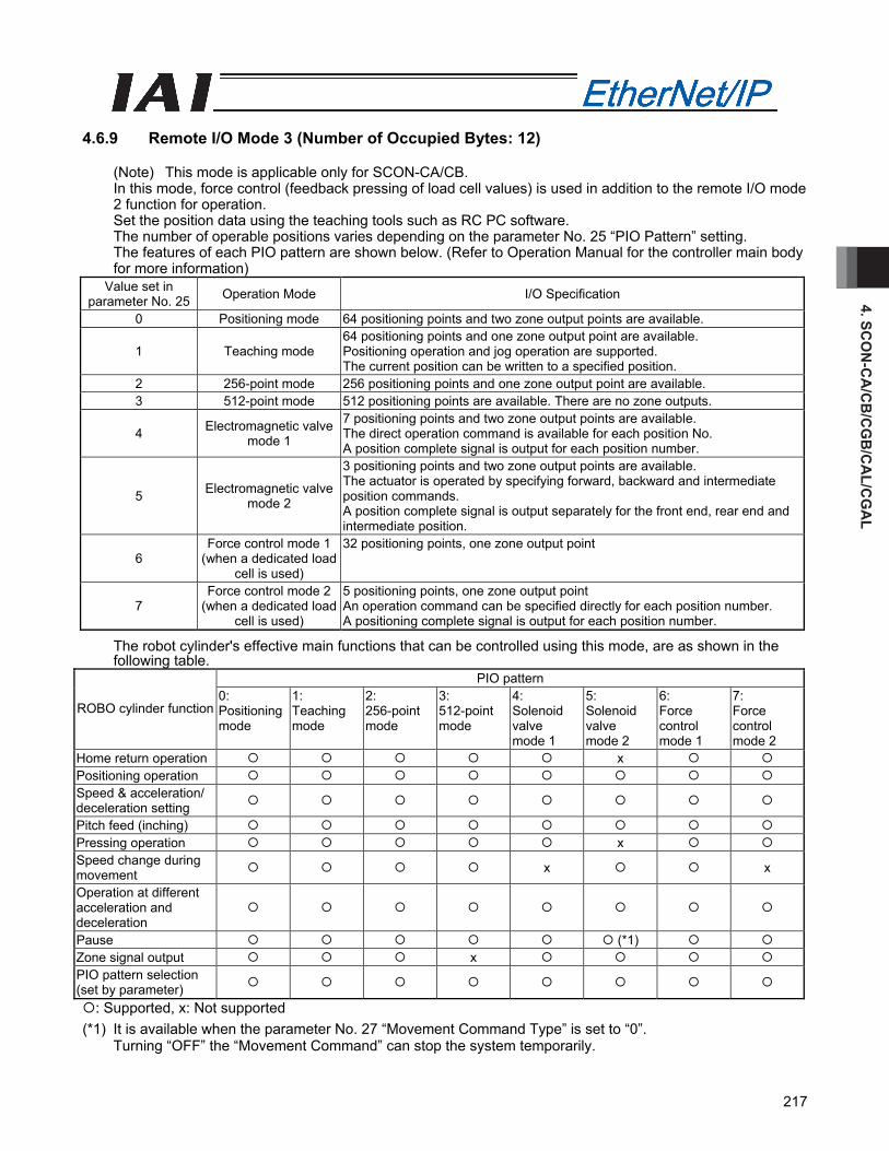
4. SCO
N-C
A/C
B/C
GB
/CA
L/CG
AL
217
4.6.9 Remote I/O Mode 3 (Number of Occupied Bytes: 12)
(Note) This mode is applicable only for SCON-CA/CB. In this mode, force control (feedback pressing of load cell values) is used in addition to the remote I/O mode 2 function for operation. Set the position data using the teaching tools such as RC PC software. The number of operable positions varies depending on the parameter No. 25 “PIO Pattern” setting. The features of each PIO pattern are shown below. (Refer to Operation Manual for the controller main body for more information)
Value set in parameter No. 25 Operation Mode I/O Specification
0 Positioning mode 64 positioning points and two zone output points are available.
1 Teaching mode 64 positioning points and one zone output point are available. Positioning operation and jog operation are supported. The current position can be written to a specified position.
2 256-point mode 256 positioning points and one zone output point are available. 3 512-point mode 512 positioning points are available. There are no zone outputs.
4 Electromagnetic valve mode 1
7 positioning points and two zone output points are available. The direct operation command is available for each position No. A position complete signal is output for each position number.
5 Electromagnetic valve mode 2
3 positioning points and two zone output points are available. The actuator is operated by specifying forward, backward and intermediate position commands. A position complete signal is output separately for the front end, rear end and intermediate position.
6 Force control mode 1
(when a dedicated load cell is used)
32 positioning points, one zone output point
7 Force control mode 2
(when a dedicated load cell is used)
5 positioning points, one zone output point An operation command can be specified directly for each position number. A positioning complete signal is output for each position number.
The robot cylinder's effective main functions that can be controlled using this mode, are as shown in the following table.
PIO pattern
ROBO cylinder function 0: Positioning mode
1: Teaching mode
2: 256-point mode
3: 512-point mode
4: Solenoid valve mode 1
5: Solenoid valve mode 2
6: Force control mode 1
7: Force control mode 2
Home return operation x Positioning operation Speed & acceleration/ deceleration setting
Pitch feed (inching) Pressing operation x Speed change during movement x x
Operation at different acceleration and deceleration
Pause (*1) Zone signal output x PIO pattern selection (set by parameter)
: Supported, x: Not supported (*1) It is available when the parameter No. 27 “Movement Command Type” is set to “0”.
Turning “OFF” the “Movement Command” can stop the system temporarily.
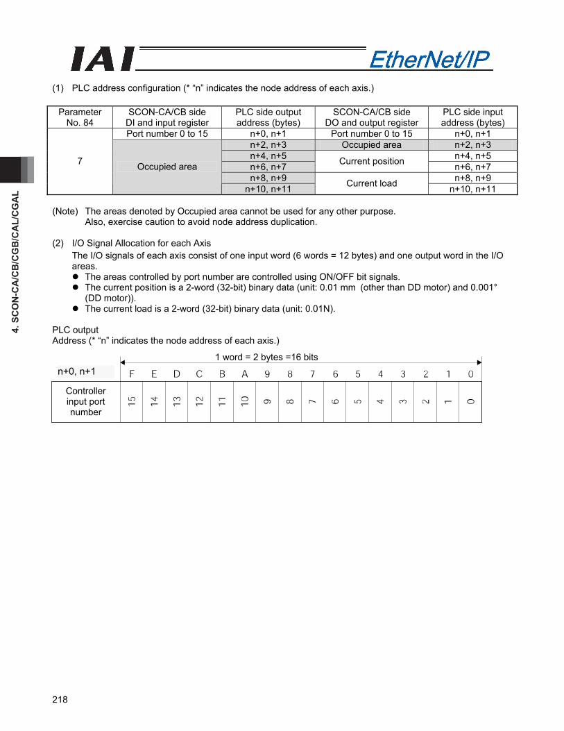
4. S
CO
N-C
A/C
B/C
GB
/CA
L/C
GA
L
218
(1) PLC address configuration (* “n” indicates the node address of each axis.)
Parameter No. 84
SCON-CA/CB side DI and input register
PLC side output address (bytes)
SCON-CA/CB side DO and output register
PLC side input address (bytes)
Port number 0 to 15 n+0, n+1 Port number 0 to 15 n+0, n+1 n+2, n+3 Occupied area n+2, n+3 n+4, n+5 n+4, n+5 n+6, n+7 Current position n+6, n+7 n+8, n+9 n+8, n+9
7 Occupied area
n+10, n+11 Current load n+10, n+11 (Note) The areas denoted by Occupied area cannot be used for any other purpose.
Also, exercise caution to avoid node address duplication. (2) I/O Signal Allocation for each Axis
The I/O signals of each axis consist of one input word (6 words = 12 bytes) and one output word in the I/O areas.
The areas controlled by port number are controlled using ON/OFF bit signals. The current position is a 2-word (32-bit) binary data (unit: 0.01 mm (other than DD motor) and 0.001°
(DD motor)). The current load is a 2-word (32-bit) binary data (unit: 0.01N).
PLC output Address (* “n” indicates the node address of each axis.)
1 word = 2 bytes =16 bits
n+0、n+1
Controller input port number
n+0, n+1
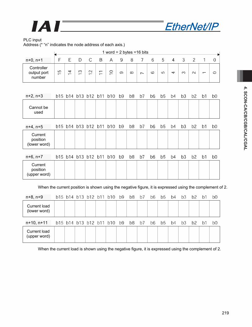
4. SCO
N-C
A/C
B/C
GB
/CA
L/CG
AL
219
PLC input Address (* “n” indicates the node address of each axis.)
When the current position is shown using the negative figure, it is expressed using the complement of 2.
When the current load is shown using the negative figure, it is expressed using the complement of 2.
1 word = 2 bytes =16 bits
Controller output port
number
Cannot be used
Current position
(lower word)
Current position
(upper word)
n+6, n+7
n+4, n+5
n+2, n+3
n+0, n+1
Current load (lower word)
Current load (upper word)
n+10, n+11
n+8, n+9
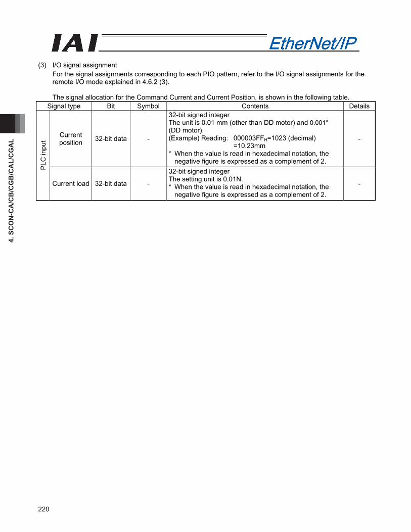
4. S
CO
N-C
A/C
B/C
GB
/CA
L/C
GA
L
220
(3) I/O signal assignment
For the signal assignments corresponding to each PIO pattern, refer to the I/O signal assignments for the remote I/O mode explained in 4.6.2 (3).
The signal allocation for the Command Current and Current Position, is shown in the following table.
Signal type Bit Symbol Contents Details
Current position 32-bit data -
32-bit signed integer The unit is 0.01 mm (other than DD motor) and 0.001° (DD motor). (Example) Reading: 000003FFH=1023 (decimal)
=10.23mm * When the value is read in hexadecimal notation, the
negative figure is expressed as a complement of 2.
-
PLC
inpu
t
Current load 32-bit data -
32-bit signed integer The setting unit is 0.01N. * When the value is read in hexadecimal notation, the
negative figure is expressed as a complement of 2. -
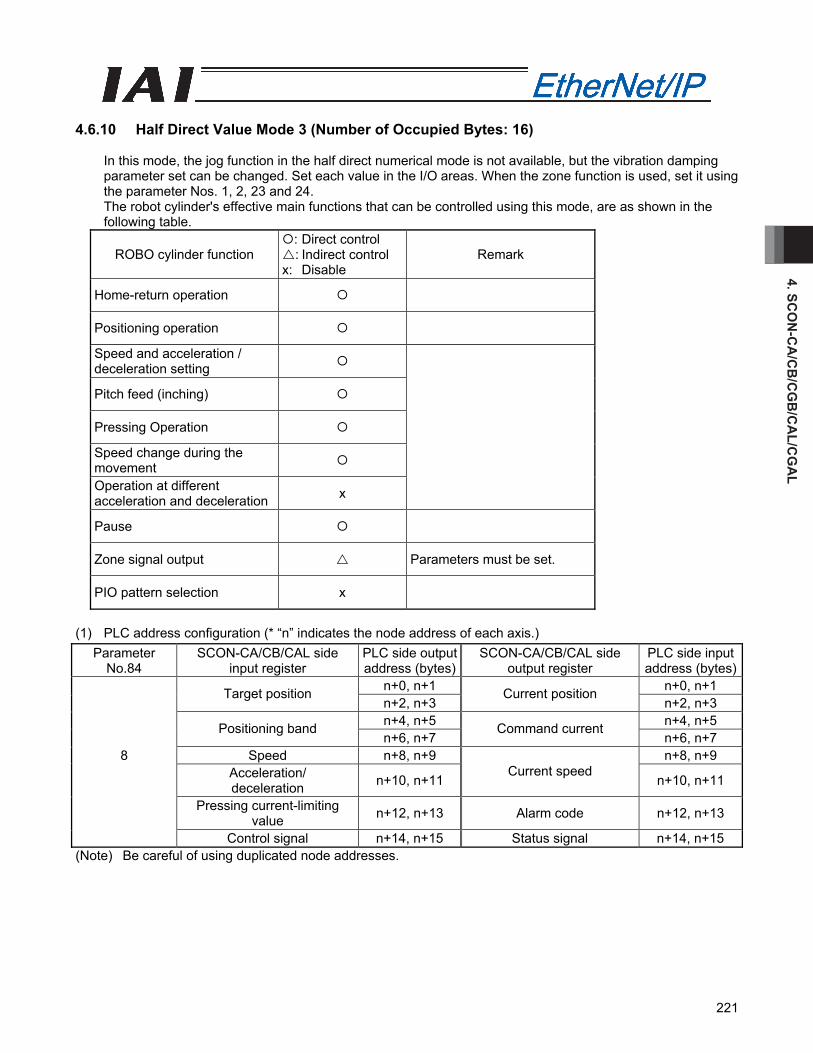
4. SCO
N-C
A/C
B/C
GB
/CA
L/CG
AL
221
4.6.10 Half Direct Value Mode 3 (Number of Occupied Bytes: 16)
In this mode, the jog function in the half direct numerical mode is not available, but the vibration damping parameter set can be changed. Set each value in the I/O areas. When the zone function is used, set it using the parameter Nos. 1, 2, 23 and 24. The robot cylinder's effective main functions that can be controlled using this mode, are as shown in the following table.
ROBO cylinder function : Direct control : Indirect control
x: Disable Remark
Home-return operation
Positioning operation
Speed and acceleration / deceleration setting
Pitch feed (inching)
Pressing Operation
Speed change during the movement
Operation at different acceleration and deceleration x
Pause
Zone signal output Parameters must be set.
PIO pattern selection x
(1) PLC address configuration (* “n” indicates the node address of each axis.)
Parameter No.84
SCON-CA/CB/CAL side input register
PLC side output address (bytes)
SCON-CA/CB/CAL side output register
PLC side input address (bytes)
n+0, n+1 n+0, n+1
Target position n+2, n+3
Current position n+2, n+3
n+4, n+5 n+4, n+5
Positioning band n+6, n+7
Command current n+6, n+7
8 Speed n+8, n+9 n+8, n+9
Acceleration/ deceleration n+10, n+11
Current speed n+10, n+11
Pressing current-limiting value n+12, n+13 Alarm code n+12, n+13
Control signal n+14, n+15 Status signal n+14, n+15 (Note) Be careful of using duplicated node addresses.

4. S
CO
N-C
A/C
B/C
GB
/CA
L/C
GA
L
222
(2) I/O Signal Allocation for each Axis
The I/O signals of each axis consist of one input word (8 words = 16 bytes) and one output word in the I/O areas.
The control signals and status signals are ON/OFF signals in units of bit. The target position and current position are expressed using 2-word (32 bits) binary data. The figures
from –999999 to +999999 (Unit: 0.01 mm (other than DD motor) and 0.001° (DD motor)) can be set in PLC. However, set the position data within the soft stroke range (0 to effective stroke length) for the actuator concerned.
Set the positioning band. The positioning band is expressed using 2-word (32 bits) binary data. The figures from 1 to +999999 (Unit: 0.01 mm (other than DD motor) and 0.001° (DD motor)) can be set in PLC.
The speed is a 1-word (16-bit) binary data. Although values from 0 to +65535 (unit: 1.0 mm/sec or 0.1 mm/sec) can be handled by the PLC, set a value not exceeding the maximum speed of the applicable actuator. Parameter No. 159, FB Half Direct Mode Speed Unit, determines the unit of measure.
Parameter No.159 setting value Speed setting unit0 1.0 mm/sec 1 0.1 mm/sec
The Acceleration/Deceleration is expressed using 1-word (16 bits) binary data. The figures from 1 to 999
(Unit: 0.01G) can be set in PLC. However, set the value that does not exceed the max. acceleration/deceleration value for the actuator in question.
The pressing current-limiting value is expressed using 1-word (16 bits) binary data. The figures from 0 (0%) to 510 (200%) can be set in PLC. However, set the value within the settable range for the pressing current-limiting value (Refer to the Catalog or Operation Manual for the actuator) for the actuator concerned.
Set Value Pressing current-limiting value
The command current is expressed using 2-word (32 bits) binary data (Unit: 1mA). The current speed is expressed using 2-word (32 bits) binary data (Unit: 0.01mm/sec). The alarm code is expressed using 1-word (16 bits) binary data.
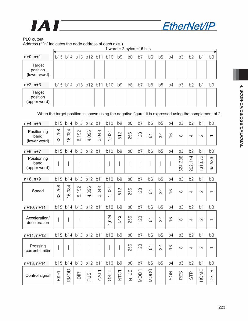
4. SCO
N-C
A/C
B/C
GB
/CA
L/CG
AL
223
PLC output Address (* “n” indicates the node address of each axis.)
When the target position is shown using the negative figure, it is expressed using the complement of 2.
Target position
(lower word)
Target position
(upper word)
1 word = 2 bytes =16 bits
n+2, n+3
n+0, n+1
Positioning band
(lower word)
Positioning band
(upper word)
Speed
Acceleration/ deceleration
Pressing current-limitin
Control signal
n+13, n+14
n+11, n+12
n+10, n+11
n+8, n+9
n+6, n+7
n+4, n+5
1,02
4
512
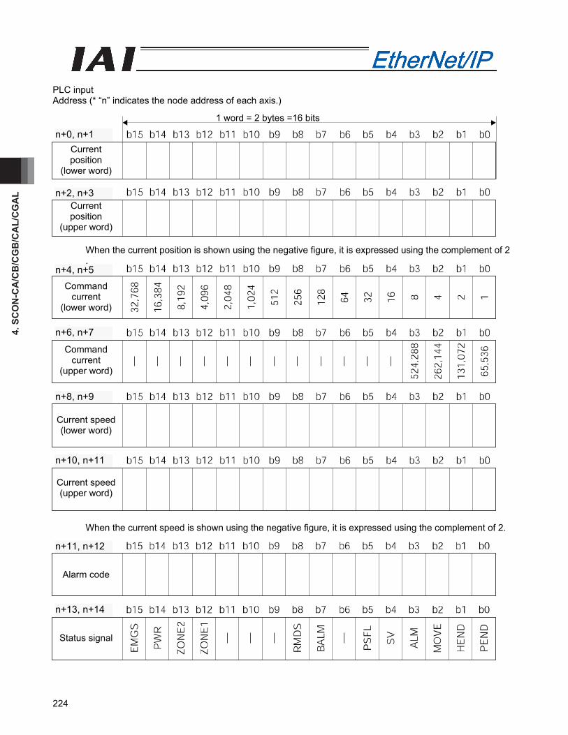
4. S
CO
N-C
A/C
B/C
GB
/CA
L/C
GA
L
224
PLC input Address (* “n” indicates the node address of each axis.)
When the current position is shown using the negative figure, it is expressed using the complement of 2 .
When the current speed is shown using the negative figure, it is expressed using the complement of 2.
1 word = 2 bytes =16 bits
Current position
(lower word)
Current position
(upper word)
n+2, n+3
n+0, n+1
Command current
(lower word)
Command current
(upper word)
Current speed (lower word)
Current speed (upper word)
n+10, n+11
n+8, n+9
n+6, n+7
n+4, n+5
Alarm code
Status signal
n+11, n+12
n+13, n+14
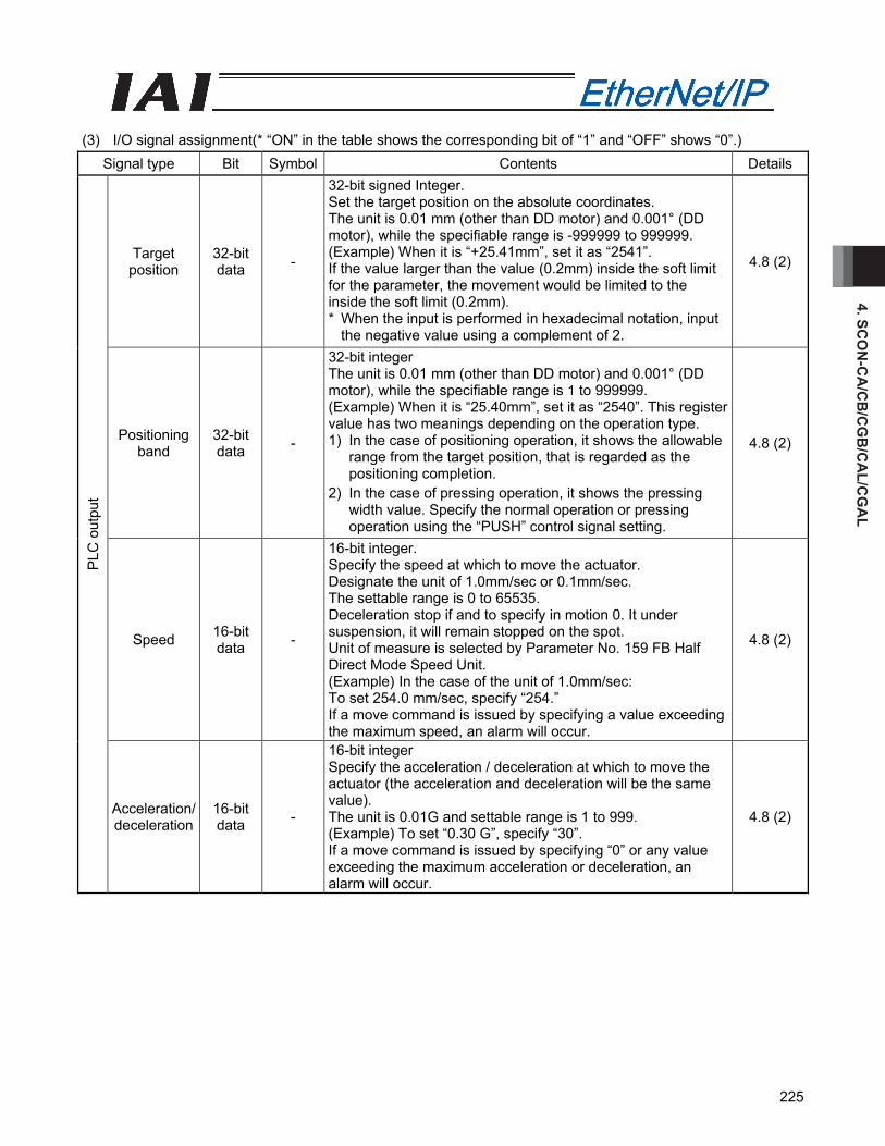
4. SCO
N-C
A/C
B/C
GB
/CA
L/CG
AL
225
(3) I/O signal assignment(* “ON” in the table shows the corresponding bit of “1” and “OFF” shows “0”.)
Signal type Bit Symbol Contents Details
Target position
32-bit data -
32-bit signed Integer. Set the target position on the absolute coordinates. The unit is 0.01 mm (other than DD motor) and 0.001° (DD motor), while the specifiable range is -999999 to 999999. (Example) When it is “+25.41mm”, set it as “2541”. If the value larger than the value (0.2mm) inside the soft limit for the parameter, the movement would be limited to the inside the soft limit (0.2mm). * When the input is performed in hexadecimal notation, input
the negative value using a complement of 2.
4.8 (2)
Positioning band
32-bit data -
32-bit integer The unit is 0.01 mm (other than DD motor) and 0.001° (DD motor), while the specifiable range is 1 to 999999. (Example) When it is “25.40mm”, set it as “2540”. This register value has two meanings depending on the operation type. 1) In the case of positioning operation, it shows the allowable
range from the target position, that is regarded as the positioning completion.
2) In the case of pressing operation, it shows the pressing width value. Specify the normal operation or pressing operation using the “PUSH” control signal setting.
4.8 (2)
Speed 16-bit data -
16-bit integer. Specify the speed at which to move the actuator. Designate the unit of 1.0mm/sec or 0.1mm/sec. The settable range is 0 to 65535. Deceleration stop if and to specify in motion 0. It under suspension, it will remain stopped on the spot. Unit of measure is selected by Parameter No. 159 FB Half Direct Mode Speed Unit. (Example) In the case of the unit of 1.0mm/sec: To set 254.0 mm/sec, specify “254.” If a move command is issued by specifying a value exceeding the maximum speed, an alarm will occur.
4.8 (2)
PLC
out
put
Acceleration/ deceleration
16-bit data -
16-bit integer Specify the acceleration / deceleration at which to move the actuator (the acceleration and deceleration will be the same value). The unit is 0.01G and settable range is 1 to 999. (Example) To set “0.30 G”, specify “30”. If a move command is issued by specifying “0” or any value exceeding the maximum acceleration or deceleration, an alarm will occur.
4.8 (2)
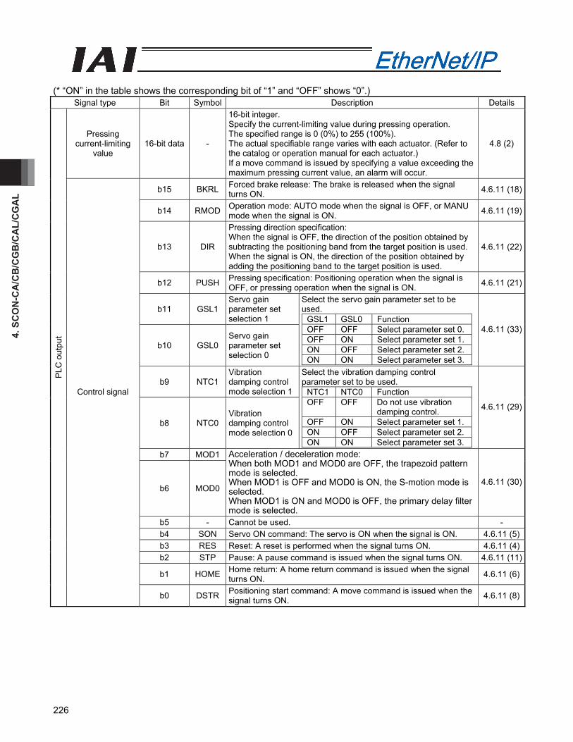
4. S
CO
N-C
A/C
B/C
GB
/CA
L/C
GA
L
226
(* “ON” in the table shows the corresponding bit of “1” and “OFF” shows “0”.)
Signal type Bit Symbol Description Details
Pressing current-limiting
value 16-bit data -
16-bit integer. Specify the current-limiting value during pressing operation. The specified range is 0 (0%) to 255 (100%). The actual specifiable range varies with each actuator. (Refer to the catalog or operation manual for each actuator.) If a move command is issued by specifying a value exceeding the maximum pressing current value, an alarm will occur.
4.8 (2)
b15 BKRL Forced brake release: The brake is released when the signal turns ON. 4.6.11 (18)
b14 RMOD Operation mode: AUTO mode when the signal is OFF, or MANU mode when the signal is ON. 4.6.11 (19)
b13 DIR
Pressing direction specification: When the signal is OFF, the direction of the position obtained by subtracting the positioning band from the target position is used. When the signal is ON, the direction of the position obtained by adding the positioning band to the target position is used.
4.6.11 (22)
b12 PUSH Pressing specification: Positioning operation when the signal is OFF, or pressing operation when the signal is ON. 4.6.11 (21)
b11 GSL1 Servo gain parameter set selection 1
b10 GSL0 Servo gain parameter set selection 0
Select the servo gain parameter set to be used.
GSL1 GSL0 Function OFF OFF Select parameter set 0.OFF ON Select parameter set 1.ON OFF Select parameter set 2.ON ON Select parameter set 3.
4.6.11 (33)
b9 NTC1 Vibration damping control mode selection 1
b8 NTC0 Vibration damping control mode selection 0
Select the vibration damping control parameter set to be used.
NTC1 NTC0 Function OFF OFF Do not use vibration
damping control. OFF ON Select parameter set 1.ON OFF Select parameter set 2.ON ON Select parameter set 3.
4.6.11 (29)
b7 MOD1
b6 MOD0
Acceleration / deceleration mode: When both MOD1 and MOD0 are OFF, the trapezoid pattern mode is selected. When MOD1 is OFF and MOD0 is ON, the S-motion mode is selected. When MOD1 is ON and MOD0 is OFF, the primary delay filter mode is selected.
4.6.11 (30)
b5 - Cannot be used. - b4 SON Servo ON command: The servo is ON when the signal is ON. 4.6.11 (5)b3 RES Reset: A reset is performed when the signal turns ON. 4.6.11 (4)b2 STP Pause: A pause command is issued when the signal turns ON. 4.6.11 (11)
b1 HOME Home return: A home return command is issued when the signal turns ON. 4.6.11 (6)
PLC
out
put
Control signal
b0 DSTR Positioning start command: A move command is issued when the signal turns ON. 4.6.11 (8)
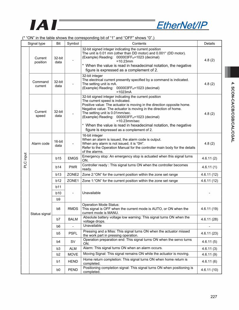
4. SCO
N-C
A/C
B/C
GB
/CA
L/CG
AL
227
(* “ON” in the table shows the corresponding bit of “1” and “OFF” shows “0”.)
Signal type Bit Symbol Contents Details
Current position
32-bit data -
32-bit signed integer indicating the current position The unit is 0.01 mm (other than DD motor) and 0.001° (DD motor). (Example) Reading: 000003FFH=1023 (decimal)
=10.23mm * When the value is read in hexadecimal notation, the negative
figure is expressed as a complement of 2.
4.8 (2)
Command current
32-bit data -
32-bit integer The electrical current presently specified by a command is indicated. The setting unit is mA. (Example) Reading: 000003FFH=1023 (decimal)
=1023mA
4.8 (2)
Current speed
32-bit data -
32-bit signed integer indicating the current position The current speed is indicated. Positive value: The actuator is moving in the direction opposite home. Negative value: The actuator is moving in the direction of home. The setting unit is 0.01mm/sec. (Example) Reading: 000003FFH=1023 (decimal)
=10.23mm/sec * When the value is read in hexadecimal notation, the negative
figure is expressed as a complement of 2.
4.8 (2)
Alarm code 16-bit data -
16-bit integer When an alarm is issued, the alarm code is output. When any alarm is not issued, it is “0H”. Refer to the Operation Manual for the controller main body for the details of the alarms.
4.8 (2)
b15 EMGS Emergency stop: An emergency stop is actuated when this signal turns ON. 4.6.11 (2)
b14 PWR Controller ready : This signal turns ON when the controller becomes ready. 4.6.11 (1)
b13 ZONE2 Zone 2:“ON” for the current position within the zone set range 4.6.11 (12)
b12 ZONE1 Zone 1:“ON” for the current position within the zone set range 4.6.11 (12)
b11
b10
b9
- Unavailable -
b8 RMDS Operation Mode Status: This signal is OFF when the current mode is AUTO, or ON when the current mode is MANU.
4.6.11 (19)
b7 BALM Absolute battery voltage low warning: This signal turns ON when the voltage drops. 4.6.11 (28)
b6 - Unavailable -
b5 PSFL Pressing and a Miss: This signal turns ON when the actuator missed the work part in pressing operation. 4.6.11 (23)
b4 SV Operation preparation end: This signal turns ON when the servo turns ON. 4.6.11 (5)
b3 ALM Alarm: This signal turns ON when an alarm occurs. 4.6.11 (3) b2 MOVE Moving Signal: This signal remains ON while the actuator is moving. 4.6.11 (9)
b1 HEND Home return completion: This signal turns ON when home return is completed. 4.6.11 (6)
PLC
inpu
t
Status signal
b0 PEND Positioning completion signal: This signal turns ON when positioning is completed. 4.6.11 (10)
4. S
CO
N-C
A/C
B/C
GB
/CA
L/C
GA
L
228
4.6.11 I/O Signal Controls and Function * ON indicates that the applicable bit signal is “1”, while OFF indicates that the bit signal is “0”.
The I/O control and functions used in the Position/Simplified Direct Value Modes 1 and 2, Half Direct Value Modes 1 to 3 and Full Direct Value Mode, are described as follows. For the I/O signals for the Remote I/O Modes 1 to 3, refer to the Operation Manual for the controller main body.
(1) Controller ready (PWR) PLC input signal
When the controller can control the system after the power injection, it is turned “ON”. ■ Function Regardless of the alarm or servo conditions, when the controller initialization is completed normally after the power injection and the controller can control the system, it is turned “ON”. Even in the alarm condition, when the controller can control the system, it is turned “ON”.
(2) Emergency stop (EMGS) PLC input signal
When the controller is stopped in an emergency, it is turned “ON”. ■ Function When the controller is stopped in an emergency (motor driving power is cut off), it is turned “ON”. When the emergency stop status is cleared, it is turned “OFF”.
(3) Alarm (ALM) PLC input signal
When any error is detected using the controller protection circuit (function), it is turned “ON”. ■ Function When any error is detected and the protection circuit (function) is activated, this signal is turned “ON”. When the cause of the alarm is eliminated and the reset signal is turned “ON”, the alarm is turned “OFF” in the case that it is the alarm with the operation cancellation level. (In the case of the alarm with the cold start level, re-injection of the power is required) When the alarm is detected, the Status Indicator LED (Refer to 4.3, "EtherNet/IP Interface”) on the front surface of the controller illuminates in red.
(4) Reset (RES) PLC output signal
This signal has two functions. It can reset the controller alarm and cancel the reminder for planned movements during pause conditions. ■ Function
[1] When this signal is turned ON from OFF condition after eliminating the cause of the alarm during the alarm output, the alarm (ALM) signal can be reset. (In the case of the alarm with the cold start level, re-injection of the power is required)
[2] When this signal is turned ON from OFF condition during the pause condition, the reminder of the planned movement left can be cancelled.
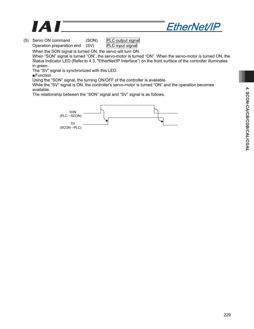
4. SCO
N-C
A/C
B/C
GB
/CA
L/CG
AL
229
(5) Servo ON command (SON) PLC output signal
Operation preparation end (SV) PLC input signal When the SON signal is turned ON, the servo will turn ON. When “SON” signal is turned “ON”, the servo-motor is turned “ON”. When the servo-motor is turned ON, the Status Indicator LED (Refer to 4.3, "EtherNet/IP Interface”) on the front surface of the controller illuminates in green. The “SV” signal is synchronized with this LED. ■ Function Using the “SON” signal, the turning ON/OFF of the controller is available. While the “SV” signal is ON, the controller's servo-motor is turned “ON” and the operation becomes available. The relationship between the “SON” signal and “SV” signal is as follows.
(SCON→PLC)
(PLC→SCON)
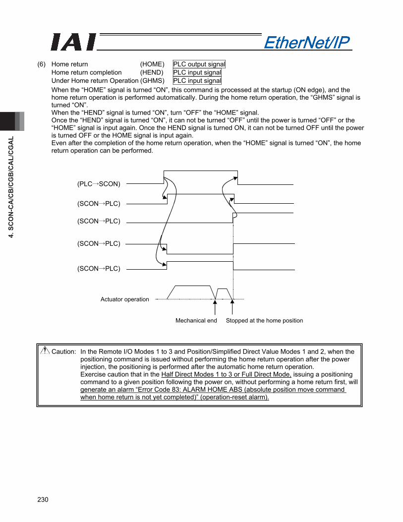
4. S
CO
N-C
A/C
B/C
GB
/CA
L/C
GA
L
230
(6) Home return (HOME) PLC output signal
Home return completion (HEND) PLC input signal Under Home return Operation (GHMS) PLC input signal When the “HOME” signal is turned “ON”, this command is processed at the startup (ON edge), and the home return operation is performed automatically. During the home return operation, the “GHMS” signal is turned “ON”. When the “HEND” signal is turned “ON”, turn “OFF” the “HOME” signal. Once the “HEND” signal is turned “ON”, it can not be turned “OFF” until the power is turned “OFF” or the “HOME” signal is input again. Once the HEND signal is turned ON, it can not be turned OFF until the power is turned OFF or the HOME signal is input again. Even after the completion of the home return operation, when the “HOME” signal is turned “ON”, the home return operation can be performed.
Caution: In the Remote I/O Modes 1 to 3 and Position/Simplified Direct Value Modes 1 and 2, when the positioning command is issued without performing the home return operation after the power injection, the positioning is performed after the automatic home return operation. Exercise caution that in the Half Direct Modes 1 to 3 or Full Direct Mode, issuing a positioning command to a given position following the power on, without performing a home return first, will generate an alarm “Error Code 83: ALARM HOME ABS (absolute position move command when home return is not yet completed)” (operation-reset alarm).
Actuator operation
Mechanical end Stopped at the home position
(SCON→PLC)
(PLC→SCON)
(SCON→PLC)
(SCON→PLC)
(SCON→PLC)
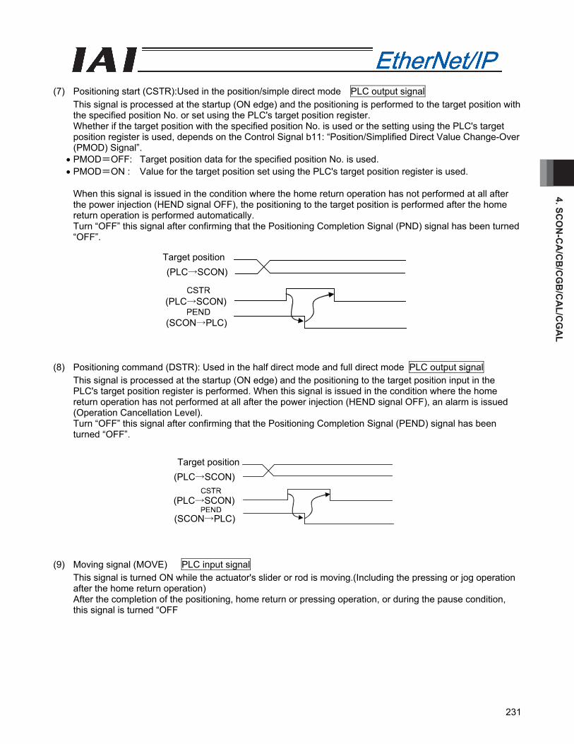
4. SCO
N-C
A/C
B/C
GB
/CA
L/CG
AL
231
(7) Positioning start (CSTR):Used in the position/simple direct mode PLC output signal
This signal is processed at the startup (ON edge) and the positioning is performed to the target position with the specified position No. or set using the PLC's target position register. Whether if the target position with the specified position No. is used or the setting using the PLC's target position register is used, depends on the Control Signal b11: “Position/Simplified Direct Value Change-Over (PMOD) Signal”.
• PMOD=OFF: Target position data for the specified position No. is used. • PMOD=ON : Value for the target position set using the PLC's target position register is used.
When this signal is issued in the condition where the home return operation has not performed at all after the power injection (HEND signal OFF), the positioning to the target position is performed after the home return operation is performed automatically. Turn “OFF” this signal after confirming that the Positioning Completion Signal (PND) signal has been turned “OFF”.
(8) Positioning command (DSTR): Used in the half direct mode and full direct mode PLC output signal
This signal is processed at the startup (ON edge) and the positioning to the target position input in the PLC's target position register is performed. When this signal is issued in the condition where the home return operation has not performed at all after the power injection (HEND signal OFF), an alarm is issued (Operation Cancellation Level). Turn “OFF” this signal after confirming that the Positioning Completion Signal (PEND) signal has been turned “OFF”.
(9) Moving signal (MOVE) PLC input signal
This signal is turned ON while the actuator's slider or rod is moving.(Including the pressing or jog operation after the home return operation) After the completion of the positioning, home return or pressing operation, or during the pause condition, this signal is turned “OFF
Target position
Target position
(SCON→PLC)
(PLC→SCON)
(PLC→SCON)
(SCON→PLC)
(PLC→SCON)
(PLC→SCON)
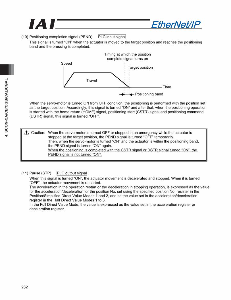
4. S
CO
N-C
A/C
B/C
GB
/CA
L/C
GA
L
232
(10) Positioning completion signal (PEND) PLC input signal
This signal is turned “ON” when the actuator is moved to the target position and reaches the positioning band and the pressing is completed.
When the servo-motor is turned ON from OFF condition, the positioning is performed with the position set as the target position. Accordingly, this signal is turned “ON” and after that, when the positioning operation is started with the home return (HOME) signal, positioning start (CSTR) signal and positioning command (DSTR) signal, this signal is turned “OFF”.
(11) Pause (STP) PLC output signal
When this signal is turned “ON”, the actuator movement is decelerated and stopped. When it is turned “OFF”, the actuator movement is restarted. The acceleration in the operation restart or the deceleration in stopping operation, is expressed as the value for the acceleration/deceleration for the position No. set using the specified position No. resister in the Position/Simplified Direct Value Modes 1 and 2, and as the value set in the acceleration/deceleration register in the Half Direct Value Modes 1 to 3. In the Full Direct Value Mode, the value is expressed as the value set in the acceleration register or deceleration register.
Caution: When the servo-motor is turned OFF or stopped in an emergency while the actuator is stopped at the target position, the PEND signal is turned “OFF” temporarily. Then, when the servo-motor is turned “ON” and the actuator is within the positioning band, the PEND signal is turned “ON” again. When the positioning is completed with the CSTR signal or DSTR signal turned “ON”, the PEND signal is not turned “ON”.
Speed
Travel
Positioning band
Time
Target position
Timing at which the position complete signal turns on
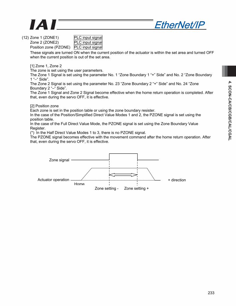
4. SCO
N-C
A/C
B/C
GB
/CA
L/CG
AL
233
(12) Zone 1 (ZONE1) PLC input signal
Zone 2 (ZONE2) PLC input signal Position zone (PZONE) PLC input signal These signals are turned ON when the current position of the actuator is within the set area and turned OFF when the current position is out of the set area.
[1] Zone 1, Zone 2 The zone is set using the user parameters. The Zone 1 Signal is set using the parameter No. 1 “Zone Boundary 1 “+” Side” and No. 2 “Zone Boundary 1 “–“ Side”. The Zone 2 Signal is set using the parameter No. 23 “Zone Boundary 2 “+” Side” and No. 24 “Zone Boundary 2 “–“ Side”. The Zone 1 Signal and Zone 2 Signal become effective when the home return operation is completed. After that, even during the servo OFF, it is effective. [2] Position zone Each zone is set in the position table or using the zone boundary resister. In the case of the Position/Simplified Direct Value Modes 1 and 2, the PZONE signal is set using the position table. In the case of the Full Direct Value Mode, the PZONE signal is set using the Zone Boundary Value Register. (*) In the Half Direct Value Modes 1 to 3, there is no PZONE signal. The PZONE signal becomes effective with the movement command after the home return operation. After that, even during the servo OFF, it is effective.
Zone signal
Actuator operation Home
Zone setting -
+ direction
Zone setting +
4. S
CO
N-C
A/C
B/C
GB
/CA
L/C
GA
L
234
(13) +Jog (JOG+) PLC output signal
–Jog (JOG–) PLC output signal This signal is the command for the jog operation startup or inching operation startup. If a + command is issued, the actuator will operate in the direction opposite home. When a – command is issued, the actuator will operate in the direction of home. [1] Jog operation Jog operation can be performed when the jog/inch switching (JISL) signal is OFF. While the “JOG+” is turned “ON”, the movement direction is to the opposite of the home and when it is turned “OFF”, the actuator is decelerated and stopped. While the JOG – is ON, the actuator will operate in the direction of home and when it is turned OFF, it is decelerated to a stop. The operation is performed based on the set values of the following parameters.
• The speed is based on the parameter value specified using the Jog Speed/Inching Distance Change-Over (JEL) signal. If the JVEL signal is OFF, the actuator operates according to parameter No. 26, “PIO jog speed”. If the JVEL signal is ON, the actuator operates according to parameter No. 47, “PIO jog speed 2”.
• The acceleration/deceleration conforms to the rate acceleration/deceleration (the specific value varies depending on the actuator).
• When both the JOG+ and JOG- signals are turned “ON”, the actuator is decelerated and stopped. [2] Inch operation The inching operation is available while the IISI signal is turned “ON”. Once it is turned “ON”, the actuator is moved as much as the inching distance. When the JOG+ is turned “ON”, the movement is to the opposite of the home and when the JOG- is turned “ON”, the movement is to the home. The operation is performed based on the set values of the following parameters.
• The speed conforms to the value of the parameter specified by the JVEL signal. If the JVEL signal is OFF, the actuator operates according to parameter No. 26, “PIO jog speed”. If the JVEL signal is ON, the actuator operates according to parameter No. 47, “PIO jog speed 2”.
• The travel conforms to the value of the parameter specified by the JVEL signal. If the JVEL signal is OFF, the actuator operates according to parameter No. 48, “PIO inch distance”. If the JVEL signal is ON, the actuator operates according to parameter No. 49, “PIO inch distance 2”.
• The Acceleration/Deceleration is based on the rated acceleration/deceleration (depending on the actuator). During the normal operation, even when the “+” Jog Signal or “-“ Jog Signal is turned “ON”, the normal operation is continued. (The Jog signal is ignored) In the pause condition, even when the “+” Jog Signal or “-“ Jog Signal is turned “ON”, the actuator is not moved. (Note) Because the software stroke limit is disabled before the home return operation, the actuator might
run against the mechanism end. Take the greatest care.
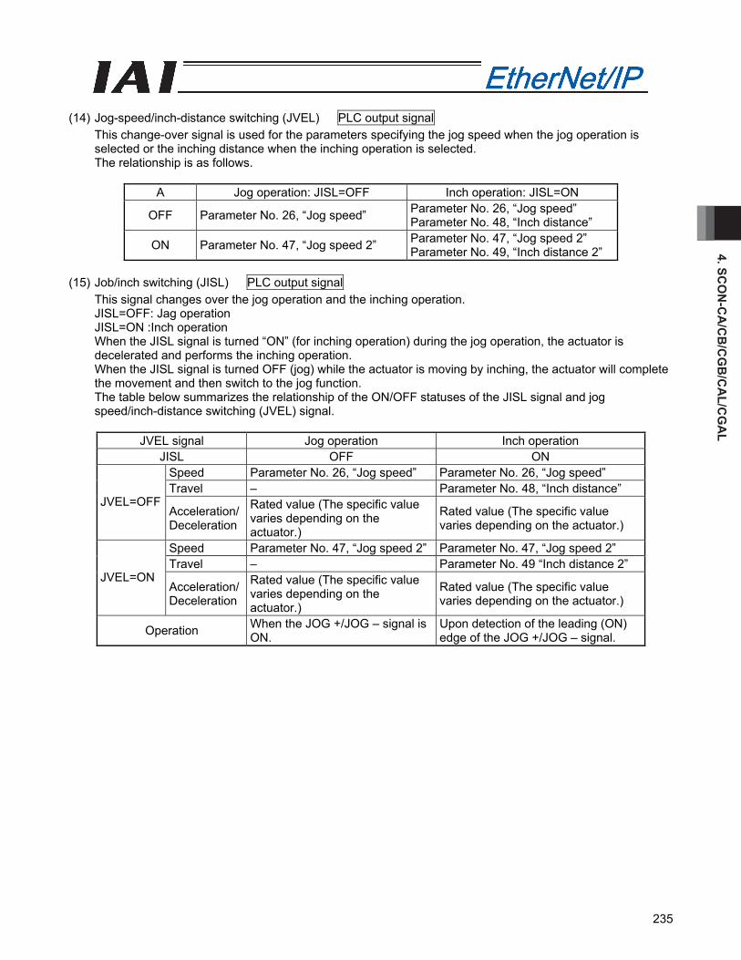
4. SCO
N-C
A/C
B/C
GB
/CA
L/CG
AL
235
(14) Jog-speed/inch-distance switching (JVEL) PLC output signal
This change-over signal is used for the parameters specifying the jog speed when the jog operation is selected or the inching distance when the inching operation is selected. The relationship is as follows.
A Jog operation: JISL=OFF Inch operation: JISL=ON
OFF Parameter No. 26, “Jog speed” Parameter No. 26, “Jog speed” Parameter No. 48, “Inch distance”
ON Parameter No. 47, “Jog speed 2” Parameter No. 47, “Jog speed 2” Parameter No. 49, “Inch distance 2”
(15) Job/inch switching (JISL) PLC output signal
This signal changes over the jog operation and the inching operation. JISL=OFF: Jag operation JISL=ON :Inch operation When the JISL signal is turned “ON” (for inching operation) during the jog operation, the actuator is decelerated and performs the inching operation. When the JISL signal is turned OFF (jog) while the actuator is moving by inching, the actuator will complete the movement and then switch to the jog function. The table below summarizes the relationship of the ON/OFF statuses of the JISL signal and jog speed/inch-distance switching (JVEL) signal.
JVEL signal Jog operation Inch operation
JISL OFF ON Speed Parameter No. 26, “Jog speed” Parameter No. 26, “Jog speed” Travel – Parameter No. 48, “Inch distance”
JVEL=OFF Acceleration/ Deceleration
Rated value (The specific value varies depending on the actuator.)
Rated value (The specific value varies depending on the actuator.)
Speed Parameter No. 47, “Jog speed 2” Parameter No. 47, “Jog speed 2” Travel – Parameter No. 49 “Inch distance 2”
JVEL=ON Acceleration/ Deceleration
Rated value (The specific value varies depending on the actuator.)
Rated value (The specific value varies depending on the actuator.)
Operation When the JOG +/JOG – signal is ON.
Upon detection of the leading (ON) edge of the JOG +/JOG – signal.
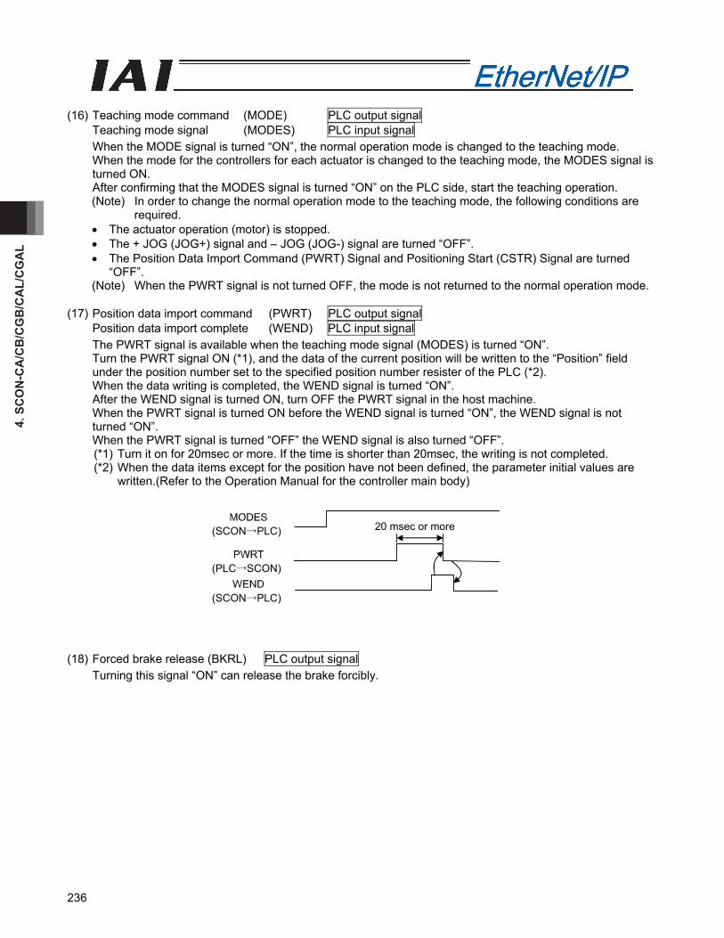
4. S
CO
N-C
A/C
B/C
GB
/CA
L/C
GA
L
236
(16) Teaching mode command (MODE) PLC output signal
Teaching mode signal (MODES) PLC input signal When the MODE signal is turned “ON”, the normal operation mode is changed to the teaching mode. When the mode for the controllers for each actuator is changed to the teaching mode, the MODES signal is turned ON. After confirming that the MODES signal is turned “ON” on the PLC side, start the teaching operation. (Note) In order to change the normal operation mode to the teaching mode, the following conditions are
required. • The actuator operation (motor) is stopped. • The + JOG (JOG+) signal and – JOG (JOG-) signal are turned “OFF”. • The Position Data Import Command (PWRT) Signal and Positioning Start (CSTR) Signal are turned
“OFF”. (Note) When the PWRT signal is not turned OFF, the mode is not returned to the normal operation mode.
(17) Position data import command (PWRT) PLC output signal
Position data import complete (WEND) PLC input signal The PWRT signal is available when the teaching mode signal (MODES) is turned “ON”. Turn the PWRT signal ON (*1), and the data of the current position will be written to the “Position” field under the position number set to the specified position number resister of the PLC (*2). When the data writing is completed, the WEND signal is turned “ON”. After the WEND signal is turned ON, turn OFF the PWRT signal in the host machine. When the PWRT signal is turned ON before the WEND signal is turned “ON”, the WEND signal is not turned “ON”. When the PWRT signal is turned “OFF” the WEND signal is also turned “OFF”. (*1) Turn it on for 20msec or more. If the time is shorter than 20msec, the writing is not completed. (*2) When the data items except for the position have not been defined, the parameter initial values are
written.(Refer to the Operation Manual for the controller main body) (18) Forced brake release (BKRL) PLC output signal
Turning this signal “ON” can release the brake forcibly.
20 msec or more
(PLC→SCON)
(SCON→PLC)
(SCON→PLC)
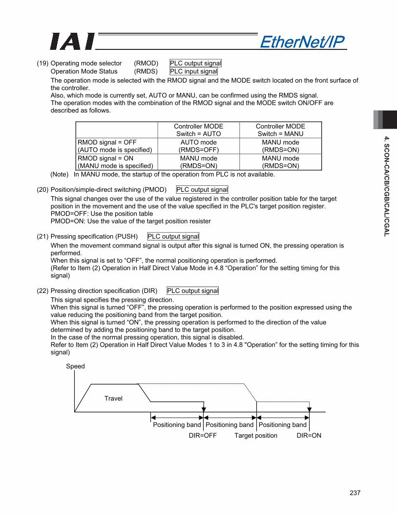
4. SCO
N-C
A/C
B/C
GB
/CA
L/CG
AL
237
(19) Operating mode selector (RMOD) PLC output signal
Operation Mode Status (RMDS) PLC input signal The operation mode is selected with the RMOD signal and the MODE switch located on the front surface of the controller. Also, which mode is currently set, AUTO or MANU, can be confirmed using the RMDS signal. The operation modes with the combination of the RMOD signal and the MODE switch ON/OFF are described as follows.
Controller MODE Switch = AUTO
Controller MODE Switch = MANU
RMOD signal = OFF (AUTO mode is specified)
AUTO mode (RMDS=OFF)
MANU mode (RMDS=ON)
RMOD signal = ON (MANU mode is specified)
MANU mode (RMDS=ON)
MANU mode (RMDS=ON)
(Note) In MANU mode, the startup of the operation from PLC is not available. (20) Position/simple-direct switching (PMOD) PLC output signal
This signal changes over the use of the value registered in the controller position table for the target position in the movement and the use of the value specified in the PLC's target position register. PMOD=OFF: Use the position table PMOD=ON: Use the value of the target position resister
(21) Pressing specification (PUSH) PLC output signal
When the movement command signal is output after this signal is turned ON, the pressing operation is performed. When this signal is set to “OFF”, the normal positioning operation is performed. (Refer to Item (2) Operation in Half Direct Value Mode in 4.8 “Operation” for the setting timing for this signal)
(22) Pressing direction specification (DIR) PLC output signal
This signal specifies the pressing direction. When this signal is turned “OFF”, the pressing operation is performed to the position expressed using the value reducing the positioning band from the target position. When this signal is turned “ON”, the pressing operation is performed to the direction of the value determined by adding the positioning band to the target position. In the case of the normal pressing operation, this signal is disabled. Refer to Item (2) Operation in Half Direct Value Modes 1 to 3 in 4.8 "Operation” for the setting timing for this signal)
Speed
Travel
Positioning band Positioning band Positioning band DIR=OFF Target position DIR=ON
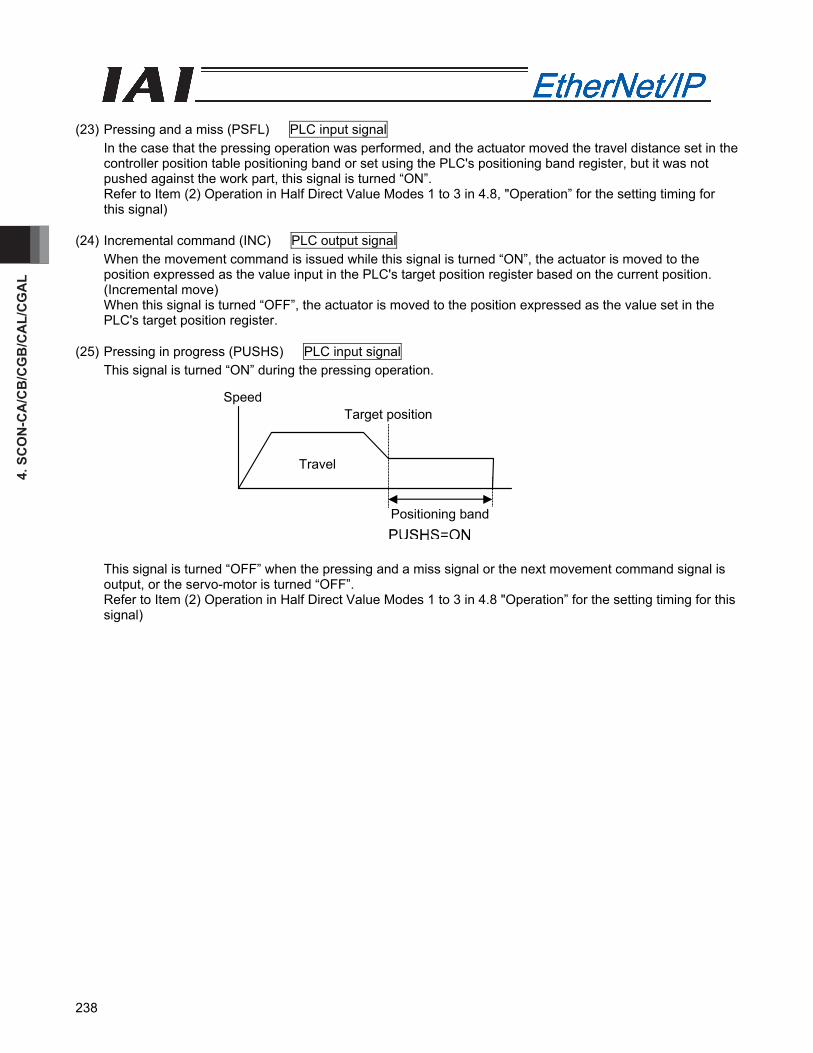
4. S
CO
N-C
A/C
B/C
GB
/CA
L/C
GA
L
238
(23) Pressing and a miss (PSFL) PLC input signal
In the case that the pressing operation was performed, and the actuator moved the travel distance set in the controller position table positioning band or set using the PLC's positioning band register, but it was not pushed against the work part, this signal is turned “ON”. Refer to Item (2) Operation in Half Direct Value Modes 1 to 3 in 4.8, "Operation” for the setting timing for this signal)
(24) Incremental command (INC) PLC output signal
When the movement command is issued while this signal is turned “ON”, the actuator is moved to the position expressed as the value input in the PLC's target position register based on the current position. (Incremental move) When this signal is turned “OFF”, the actuator is moved to the position expressed as the value set in the PLC's target position register.
(25) Pressing in progress (PUSHS) PLC input signal
This signal is turned “ON” during the pressing operation.
This signal is turned “OFF” when the pressing and a miss signal or the next movement command signal is output, or the servo-motor is turned “OFF”. Refer to Item (2) Operation in Half Direct Value Modes 1 to 3 in 4.8 "Operation” for the setting timing for this signal)
Positioning band
Target position
Travel
Speed

4. SCO
N-C
A/C
B/C
GB
/CA
L/CG
AL
239
(26) Load output judgment (LOAD) PLC input signal
This signal is available only in the pressing operation. When this signal is used for pressing-in purpose, it should be know whether if the set load threshold is reached during the pressing operation. The load threshold and check range are set by the PLC and the LOAD signal will turn ON when the command torque (motor current) exceeds the threshold inside the check range. This signal judges the load output based on the fact that the command torque excesses the threshold for the specified time period. This processing procedure is the same as for the pressing judgment. The judgment time period can be changed freely using the parameter No. 50 “Load Output Judgment Time Period”. This signal is continued until the next movement command is received.
• Set the pressing speed using the parameter No. 34 “Pressing Speed”. When the machine is delivered, it has been individually set depending on the actuator characteristics. Set an appropriate speed considering the work part material and shape. • Set the parameter No. 50 “Load Output Judgment Time Period”. • Set the threshold inspected width using the PLC's Zone Boundary + Register or Zone Boundary - Register. • Set the threshold using the PLC's Load Current Threshold Register. • Set the positioning band using the PLC's Positioning Band Register. Set it a bit longer from the backmost position considering the mechanical dispersion of the work part. Refer to the Operation Manual for the controller for more information.
Caution: The actuator continues to push the work part with the pressing current at the stop time decided with the current-limiting value. It is not the stop condition, so take the greatest care to deal with it.
Position where this signal is turned ON when the command
torque exceeds the threshold within the torque inspected width
Position where the actuator is pushed against the work and the pressing completion is judged so the positioning completion signal is turned “ON”
Speed
Travel
Positioning band (Max. pressing level)
Check range
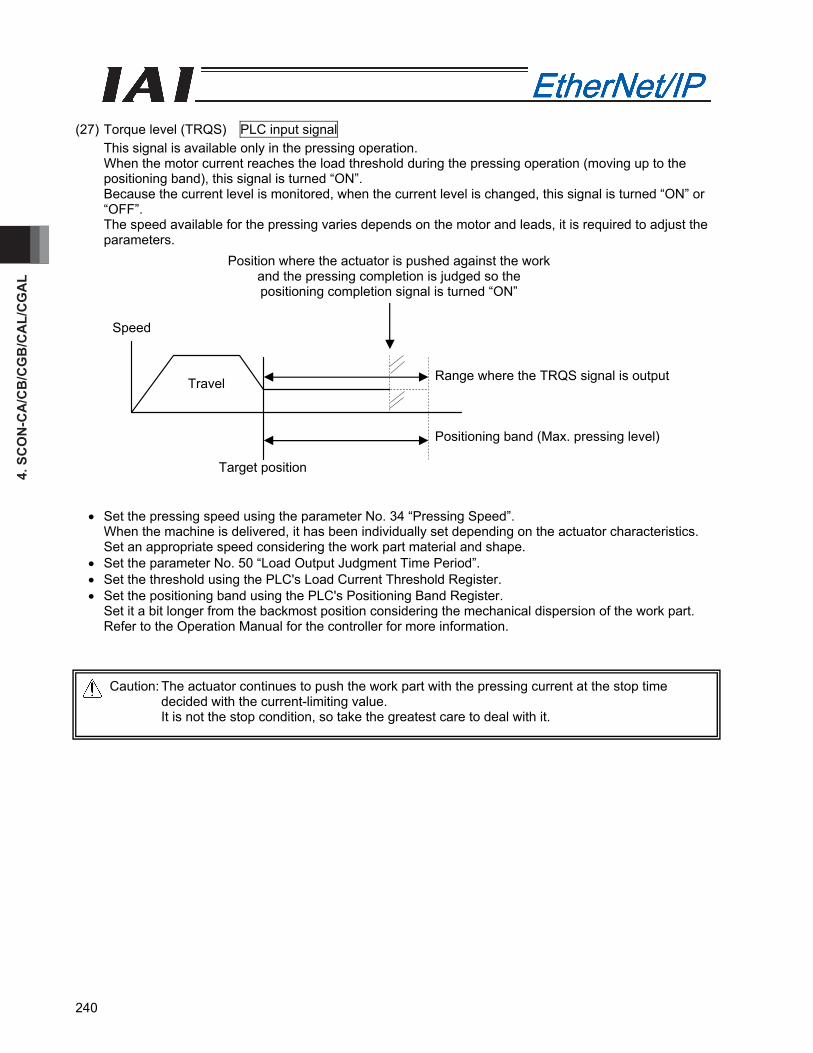
4. S
CO
N-C
A/C
B/C
GB
/CA
L/C
GA
L
240
(27) Torque level (TRQS) PLC input signal
This signal is available only in the pressing operation. When the motor current reaches the load threshold during the pressing operation (moving up to the positioning band), this signal is turned “ON”. Because the current level is monitored, when the current level is changed, this signal is turned “ON” or “OFF”. The speed available for the pressing varies depends on the motor and leads, it is required to adjust the parameters.
• Set the pressing speed using the parameter No. 34 “Pressing Speed”. When the machine is delivered, it has been individually set depending on the actuator characteristics. Set an appropriate speed considering the work part material and shape. • Set the parameter No. 50 “Load Output Judgment Time Period”. • Set the threshold using the PLC's Load Current Threshold Register. • Set the positioning band using the PLC's Positioning Band Register. Set it a bit longer from the backmost position considering the mechanical dispersion of the work part. Refer to the Operation Manual for the controller for more information.
Caution: The actuator continues to push the work part with the pressing current at the stop time decided with the current-limiting value. It is not the stop condition, so take the greatest care to deal with it.
Speed
Travel
Target position
Position where the actuator is pushed against the work and the pressing completion is judged so the positioning completion signal is turned “ON”
Positioning band (Max. pressing level)
Range where the TRQS signal is output

4. SCO
N-C
A/C
B/C
GB
/CA
L/CG
AL
241
(28) Absolute battery voltage low 2arning (BALM) PLC input signal
With an absolute system, this signal is OFF when the absolute battery voltage is normal. It remains OFF with an incremental system. This BALM signal turns ON when the absolute battery voltage drops to 3.1 V. If the controller is operated continuously and the voltage drops further to 2.5 V, the controller can no longer retain position information. (If you are using an absolute system and this signal turns ON, replace the battery at the earliest opportunity.)
(29) Vibration damping mode selection 0, 1 (NTC0, NTC1) PLC output signals
The vibration damping control function suppresses the load vibration induced by IAI’s actuator. Measure the vibration frequency and set it in a parameter. In another parameter, select and set an appropriate option based on a combination of these signals. For details, refer to the operation manual for your controller.
NTC1 NTC0 Function Remarks OFF OFF Do not use vibration damping
control. Factory setting
OFF ON Select parameter set 1 ON OFF Select parameter set 2 ON ON Select parameter set 3
Input timing An input timing chart of NTC0/NTC1 signals is shown below.
Caution: Since the statuses of NTC0/NTC1 signals are loaded when a movement command (DSTR) is recognized, nothing happens when the NTC0/NTC1 signals are turned ON/OFF while the actuator is moving.
Target position
* T1: 0 ms or greater
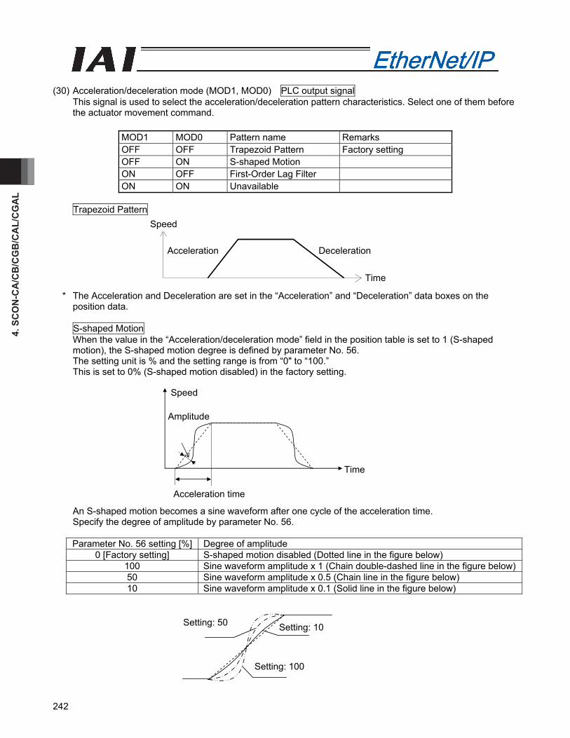
4. S
CO
N-C
A/C
B/C
GB
/CA
L/C
GA
L
242
(30) Acceleration/deceleration mode (MOD1, MOD0) PLC output signal
This signal is used to select the acceleration/deceleration pattern characteristics. Select one of them before the actuator movement command.
MOD1 MOD0 Pattern name Remarks OFF OFF Trapezoid Pattern Factory setting OFF ON S-shaped Motion ON OFF First-Order Lag Filter ON ON Unavailable
Trapezoid Pattern
* The Acceleration and Deceleration are set in the “Acceleration” and “Deceleration” data boxes on the position data. S-shaped Motion When the value in the “Acceleration/deceleration mode” field in the position table is set to 1 (S-shaped motion), the S-shaped motion degree is defined by parameter No. 56. The setting unit is % and the setting range is from “0" to “100.” This is set to 0% (S-shaped motion disabled) in the factory setting.
An S-shaped motion becomes a sine waveform after one cycle of the acceleration time. Specify the degree of amplitude by parameter No. 56.
Parameter No. 56 setting [%] Degree of amplitude
0 [Factory setting] S-shaped motion disabled (Dotted line in the figure below) 100 Sine waveform amplitude x 1 (Chain double-dashed line in the figure below)50 Sine waveform amplitude x 0.5 (Chain line in the figure below) 10 Sine waveform amplitude x 0.1 (Solid line in the figure below)
Setting: 50
Setting: 100
Setting: 10
Acceleration time
Time
Amplitude
Speed
Speed
Acceleration Deceleration
Time
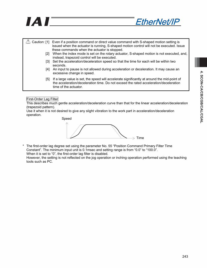
4. SCO
N-C
A/C
B/C
GB
/CA
L/CG
AL
243
First-Order Lag Filter This describes much gentle acceleration/deceleration curve than that for the linear acceleration/deceleration (trapezoid pattern). Use it when it is not desired to give any slight vibration to the work part in acceleration/deceleration operation.
* The first-order lag degree set using the parameter No. 55 “Position Command Primary Filter Time
Constant”. The minimum input unit is 0.1msec and setting range is from “0.0” to “100.0”. When it is set to “0”, the first-order lag filter is disabled. However, the setting is not reflected on the jog operation or inching operation performed using the teaching tools such as PC.
Caution: [1] Even if a position command or direct value command with S-shaped motion setting is issued when the actuator is running, S-shaped motion control will not be executed. Issue these commands when the actuator is stopped.
[2] When the index mode is set on the rotary actuator, S-shaped motion is not executed, and, instead, trapezoid control will be executed.
[3] Set the acceleration/deceleration speed so that the time for each will be within two seconds.
[4] An input to pause is not allowed during acceleration or deceleration. It may cause an excessive change in speed.
[5] If a large value is set, the speed will accelerate significantly at around the mid-point of the acceleration/deceleration time. Do not exceed the rated acceleration/deceleration time of the actuator.
Speed
Time
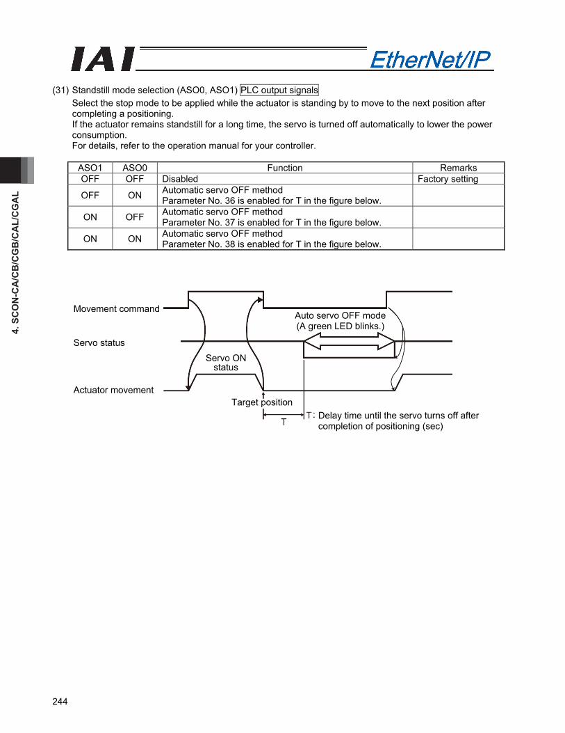
4. S
CO
N-C
A/C
B/C
GB
/CA
L/C
GA
L
244
(31) Standstill mode selection (ASO0, ASO1) PLC output signals
Select the stop mode to be applied while the actuator is standing by to move to the next position after completing a positioning. If the actuator remains standstill for a long time, the servo is turned off automatically to lower the power consumption. For details, refer to the operation manual for your controller.
ASO1 ASO0 Function Remarks OFF OFF Disabled Factory setting
OFF ON Automatic servo OFF method Parameter No. 36 is enabled for T in the figure below.
ON OFF Automatic servo OFF method Parameter No. 37 is enabled for T in the figure below.
ON ON Automatic servo OFF method Parameter No. 38 is enabled for T in the figure below.
Movement command
Servo ON status
Auto servo OFF mode (A green LED blinks.)
Delay time until the servo turns off after completion of positioning (sec)
Target position
Servo status
Actuator movement
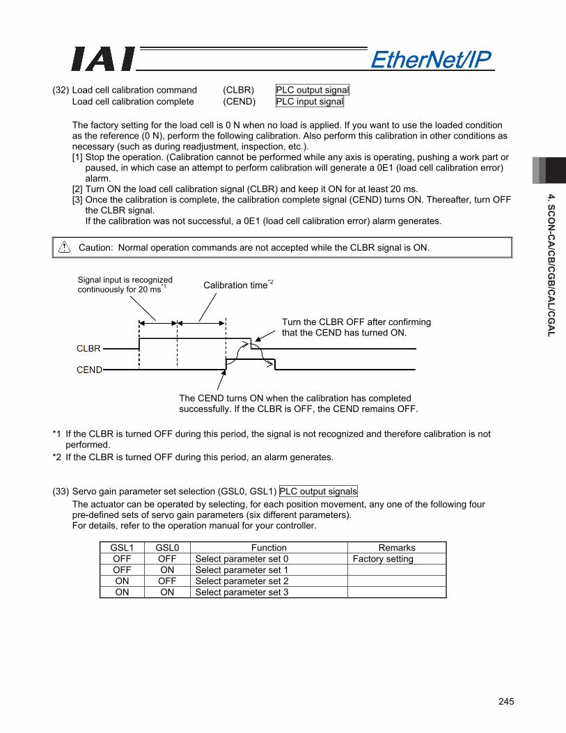
4. SCO
N-C
A/C
B/C
GB
/CA
L/CG
AL
245
(32) Load cell calibration command (CLBR) PLC output signal
Load cell calibration complete (CEND) PLC input signal The factory setting for the load cell is 0 N when no load is applied. If you want to use the loaded condition as the reference (0 N), perform the following calibration. Also perform this calibration in other conditions as necessary (such as during readjustment, inspection, etc.). [1] Stop the operation. (Calibration cannot be performed while any axis is operating, pushing a work part or
paused, in which case an attempt to perform calibration will generate a 0E1 (load cell calibration error) alarm.
[2] Turn ON the load cell calibration signal (CLBR) and keep it ON for at least 20 ms. [3] Once the calibration is complete, the calibration complete signal (CEND) turns ON. Thereafter, turn OFF
the CLBR signal. If the calibration was not successful, a 0E1 (load cell calibration error) alarm generates.
Caution: Normal operation commands are not accepted while the CLBR signal is ON.
*1 If the CLBR is turned OFF during this period, the signal is not recognized and therefore calibration is not
performed. *2 If the CLBR is turned OFF during this period, an alarm generates. (33) Servo gain parameter set selection (GSL0, GSL1) PLC output signals
The actuator can be operated by selecting, for each position movement, any one of the following four pre-defined sets of servo gain parameters (six different parameters). For details, refer to the operation manual for your controller.
GSL1 GSL0 Function Remarks OFF OFF Select parameter set 0 Factory setting OFF ON Select parameter set 1 ON OFF Select parameter set 2 ON ON Select parameter set 3
Signal input is recognized continuously for 20 ms*1 Calibration time*2
Turn the CLBR OFF after confirming that the CEND has turned ON.
The CEND turns ON when the calibration has completed successfully. If the CLBR is OFF, the CEND remains OFF.
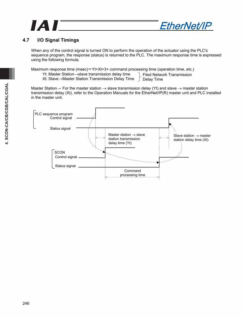
4. S
CO
N-C
A/C
B/C
GB
/CA
L/C
GA
L
246
4.7 I/O Signal Timings
When any of the control signal is turned ON to perform the operation of the actuator using the PLC's sequence program, the response (status) is returned to the PLC. The maximum response time is expressed using the following formula. Maximum response time (msec)=Yt+Xt+3+ command processing time (operation time, etc.)
Yt: Master Station→slave transmission delay time Xt: Slave→Master Station Transmission Delay Time
Master Station→ For the master station → slave transmission delay (Yt) and slave → master station transmission delay (Xt), refer to the Operation Manuals for the EtherNet/IP(R) master unit and PLC installed in the master unit.
Filed Network Transmission Delay Time
Command processing time
PLC sequence program Control signal
Status signal
SCON Control signal Status signal
Master station → slave station transmission delay time (Yt)
Slave station → master station delay time (Xt)
4. SCO
N-C
A/C
B/C
GB
/CA
L/CG
AL
247
4.8 Operation
The timings for the basic operation examples in the Position/Simplified Direct Value Mode 1 and 2 , Half Direct Value Mode 1 to 3 and Full Direct Value Mode, are described. For the Remote I/O Mode 1 to 3, refer to the Operation Manual for the controller main body. (In remote I/O mode 2 and 3, read the current position and command current or current load from the respective byte of the PLC, as deemed appropriate.)
(1) Operation in the position/simple-direct mode 1 and 2
It is operated with the position data written in the PLC's register and the speed, acceleration /deceleration, positioning band and pressing current-limiting value, etc. set using the position table.
Example of operation (normal positioning operation) (Preparation) Set the position data items (speed, acceleration/deceleration, positioning band, etc) except
for the target position item, in the position table. Turn on the Position/Simplified Direct Value Change-Over Signal (PMOD).
[1] Set the target position data in the target position register. [2] Set the position No. where the speed and acceleration/deceleration, etc., have been set, in the setup
position No. register. [3] In the condition where the positioning completion (PEND) signal is turned “ON” or, Under Movement
(MOVE) signal is turned “OFF”, turn “ON” the Positioning Start (CSTR) signal. The data items set in Steps 1) and 2) are read in the controller at the startup (ON edge) of the CSTR signal.
The data items set in Steps 1) and 2) are read in the controller at the startup (ON edge) of the CSTR signal.
[4] After the CST signal is turned “ON”, the PEND signal is turned OFF after tdpf. [5] After confirming that the PEND signal is turned “OFF” or MOVE signal is turned “ON”, turn “OFF” the
CSTR signal. Do not change the value in the target position register until the CSRT signal is turned “OFF”.
[6] At the same time when the PEND signal is turned “OFF”, the MOVE signal is turned “ON”. [7] The current position data is continuously updated. When the remaining travel distance becomes within
the range of the positioning band set in the position data, and the CSTR signal is turned “OFF”, the PEND signal is turned “ON”. Then, the completed position No. is output to the completed position No. register.
Accordingly, for the read of the completed position No. register when the positioning is completed, confirm it some time (Remaining Travel Distance Movement Time) after the PEND signal is turned “ON”.
The current position data might be changed slightly even when the system is stopped. [8] The target position data can be changed during the actuator movement. In order to change the target position, change the target data and turn ON the CSTR signal after the
time longer than the PLC scanning time has passed. Change the value for the CSTR signal after the time longer than the PLC scanning time has passed.
Example of operation (Pressing Operation) For the pressing operation, the current-limiting value is set in the pressing data box on the position data at the preparation stage. When the positioning is performed onto the position No. for which the value is set in the pressing data box, the pressing operation is performed.
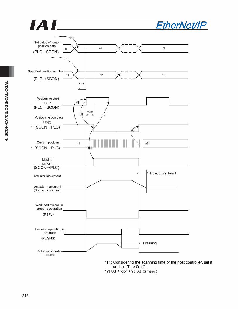
4. S
CO
N-C
A/C
B/C
GB
/CA
L/C
GA
L
248
*T1: Considering the scanning time of the host controller, set it so that “T1 ≥ 0ms”.
*Yt+Xt ≤ tdpf ≤ Yt+Xt+3(msec)
Positioning start
Positioning complete
Current position [6]
[7]
* tdpf
SCON
SCON
[1]
[2]
Set value of target position data
Specified position number
Moving
Positioning band
[3]
[4] [5]
Actuator movement (Normal positioning)
Work part missed in pressing operation
Pressing operation in progress
Actuator operation (push)
Pressing
Actuator movement
* T1
(PLC→SCON)
(SCON→PLC)
(SCON→PLC)
(PLC→SCON)
(PLC→SCON)
(SCON→PLC)
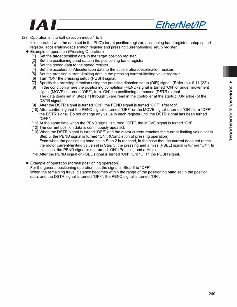
4. SCO
N-C
A/C
B/C
GB
/CA
L/CG
AL
249
(2) Operation in the half direction mode 1 to 3
It is operated with the data set in the PLC's target position register, positioning band register, setup speed register, acceleration/deceleration register and pressing current-limiting setup register.
Example of operation (Pressing Operation) [1] Set the target position data in the target position register. [2] Set the positioning band data in the positioning band register. [3] Set the speed data to the speed resister. [4] Set the acceleration/deceleration data to the acceleration/deceleration resister. [5] Set the pressing current-limiting data in the pressing current-limiting value register. [6] Turn “ON” the pressing setup (PUSH) signal. [7] Specify the pressing direction using the pressing direction setup (DIR) signal. (Refer to 4.6.11 (22)) [8] In the condition where the positioning completion (PEND) signal is turned “ON” or under movement
signal (MOVE) is turned “OFF”, turn “ON” the positioning command (DSTR) signal. The data items set in Steps 1) through 5) are read in the controller at the startup (ON edge) of the DSTR signal.
[9] After the DSTR signal is turned “ON”, the PEND signal is turned “OFF” after tdpf. [10] After confirming that the PEND signal is turned “OFF” or the MOVE signal is turned “ON”, turn “OFF”
the DSTR signal. Do not change any value in each register until the DSTR signal has been turned “OFF”.
[11] At the same time when the PEND signal is turned “OFF”, the MOVE signal is turned “ON”. [12] The current position data is continuously updated. [13] When the DSTR signal is turned “OFF” and the motor current reaches the current-limiting value set in
Step 5, the PEND signal is turned “ON”. (Completion of pressing operation) Even when the positioning band set in Step 2 is reached, in the case that the current does not reach the motor current-limiting value set in Step 5, the pressing and a miss (PSEL) signal is turned "ON”. In this case, the PEND signal is not turned “ON” (Pressing and a Miss).
[14] After the PEND signal or PSEL signal is turned “ON”, turn “OFF” the PUSH signal.
Example of operation (normal positioning operation) For the general positioning operation, set the signal in Step 6 to “OFF”. When the remaining travel distance becomes within the range of the positioning band set in the position data, and the DSTR signal is turned “OFF”, the PEND signal is turned “ON”.
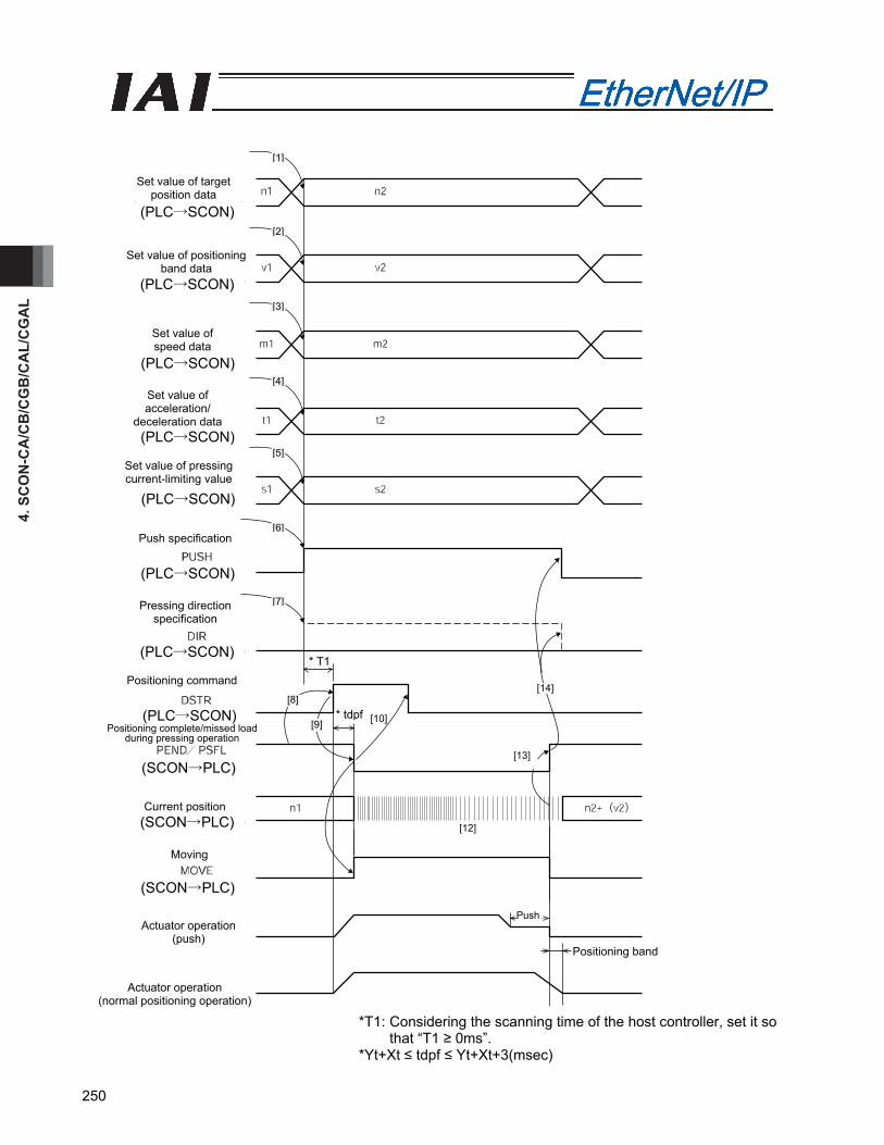
4. S
CO
N-C
A/C
B/C
GB
/CA
L/C
GA
L
250
*T1: Considering the scanning time of the host controller, set it so that “T1 ≥ 0ms”.
*Yt+Xt ≤ tdpf ≤ Yt+Xt+3(msec)
Set value of target position data
[1]
[9] [10]
[14]
Positioning band
Set value of positioning band data
Set value of speed data
Set value of acceleration/
deceleration data
Set value of pressing current-limiting value
Push specification
Pressing direction specification
Positioning command
Current position
Moving
Actuator operation (push)
Actuator operation (normal positioning operation)
Push
[13]
[12]
[2]
[3]
[4]
[5]
[6]
[7]
[8]
* T1
* tdpf
(SCON→PLC)
(SCON→PLC)
(SCON→PLC)
(PLC→SCON)
(PLC→SCON)
(PLC→SCON)
(PLC→SCON)
(PLC→SCON)
(PLC→SCON)
(PLC→SCON)
(PLC→SCON)
Positioning complete/missed load during pressing operation

4. SCO
N-C
A/C
B/C
GB
/CA
L/CG
AL
251
(3) Operation in the full direct mode
The actuator is operated by specifying all conditions required for positioning such as the target position resister and positioning band resister of the PLC.
Example of operation (Pressing Operation) [1] Set the target position data in the target position register. [2] Set the positioning band data in the positioning band register. [3] Set the speed data to the speed resister. [4] Set the position zone output boundary data in the zone boundary + register or zone boundary -
register. [5] Set the acceleration data in the acceleration register. [6] Set the deceleration data in the deceleration register. [7] Set the pressing current-limiting data in the pressing current-limiting value register. [8] Set the load current threshold data in the load current threshold setup register. [9] Turn “ON” the pressing setup (PUSH) signal. [10] Specify the pressing direction using the pressing direction setup (DIR) signal.(Refer to 4.6.11 (22)) [11] In the condition where the positioning completion (PEND) signal is turned “ON” or under movement
signal (MOVE) is turned “OFF”, turn “ON” the positioning command (DSTR) signal. The data items set in Steps 1) through 8) are read in the controller at the startup (ON edge) of the
DSTR signal. [12] After the DSTR signal is turned “ON”, the PEND signal is turned “OFF” after tpdf. [13] After confirming that the PEND signal is turned “OFF” or the MOVE signal is turned “ON”, turn “OFF”
the DSTR signal. Do not change any value in each register until the DSTR signal has been turned “OFF”.
[14] At the same time when the PEND signal is turned “OFF”, the MOVE signal is turned “ON”. [15] The current position data is continuously updated. [16] When the DSTR signal is turned “OFF” and the motor current reaches the current-limiting value set in
Step 7, the PEND signal is turned “ON” (Completion of pressing operation) Even when the positioning band set in Step 2 is reached, in the case that the current does not reach
the motor current-limiting value set in Step 7, the pressing and a miss (PSEL) signal is turned "ON”. In this case, the PEND signal is not turned “ON” (Pressing and a Miss).
[17] After the PEND signal or PSEL signal is turned “ON”, turn “OFF” the PUSH signal.
Example of operation (normal positioning operation) For the general positioning operation, set the signal in Step 9 to “OFF”. When the remaining travel distance becomes within the range of the positioning band set in the position data, and the DSTR signal is turned “OFF”, the PEND signal is turned “ON”.
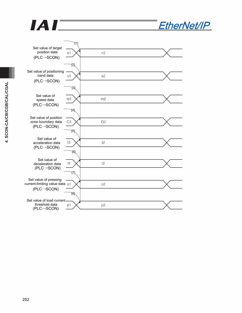
4. S
CO
N-C
A/C
B/C
GB
/CA
L/C
GA
L
252
Set value of target position data
[1]
[2]
Set value of positioning band data
Set value of speed data
[3]
[4]
[5]
[6]
[7]
[8]
Set value of position zone boundary data
Set value of acceleration data
Set value of deceleration data
Set value of pressing current-limiting value data
Set value of load current threshold data
(PLC→SCON)
(PLC→SCON)
(PLC→SCON)
(PLC→SCON)
(PLC→SCON)
(PLC→SCON)
(PLC→SCON)
(PLC→SCON)

4. SCO
N-C
A/C
B/C
GB
/CA
L/CG
AL
253
* T1: Considering the scanning time of the host controller, set it so that “T1 ≥ 0ms”.
* Yt+Xt ≤ tdpf ≤ Yt+Xt+3(msec)
[9]
Positioning band
Push specification
Push direction specification
Positioning command
Positioning complete/missed load during pressing operation
Current position
Moving
Actuator operation (push)
Actuator operation (normal positioning
operation)
Push
[11]
[13]
[15]
[16]
[17]
[10]
[12]
[14]
* T1
* tdpf
(PLC→SCON)
(PLC→SCON)
(PLC→SCON)
(SCON→PLC)
(SCON→PLC)
(SCON→PLC)
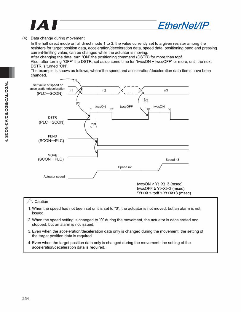
4. S
CO
N-C
A/C
B/C
GB
/CA
L/C
GA
L
254
(4) Data change during movement
In the half direct mode or full direct mode 1 to 3, the value currently set to a given resister among the resisters for target position data, acceleration/deceleration data, speed data, positioning band and pressing current-limiting value, can be changed while the actuator is moving. After changing the data, turn “ON” the positioning command (DSTR) for more than tdpf. Also, after turning “OFF” the DSTR, set aside some time for “twcsON + twcsOFF” or more, until the next DSTR is turned “ON”. The example is shows as follows, where the speed and acceleration/deceleration data items have been changed.
twcsON ≥ Yt+Xt+3 (msec) twcsOFF ≥ Yt+Xt+3 (msec) *Yt+Xt ≤ tpdf ≤ Yt+Xt+3 (msec)
Caution
1. When the speed has not been set or it is set to “0”, the actuator is not moved, but an alarm is not issued.
2. When the speed setting is changed to “0” during the movement, the actuator is decelerated and stopped, but an alarm is not issued.
3. Even when the acceleration/deceleration data only is changed during the movement, the setting of the target position data is required.
4. Even when the target position data only is changed during the movement, the setting of the acceleration/deceleration data is required.
[3]
Set value of speed or acceleration/deceleration
[1]
[2]
Actuator speed
Speed n2
Speed n3
(PLC→SCON)
(PLC→SCON)
(SCON→PLC)
(SCON→PLC)

4. SCO
N-C
A/C
B/C
GB
/CA
L/CG
AL
255
4.9 EtherNet/IP Related Parameters
Parameters relating to EtherNet/IP are No. 84 to No. 87, No. 90, No. 140 to No. 142 and No.159. . Category: C: External interface parameter
No. Category Symbol Name Default value set in the factory before delivery
1
~ 83
Refer to operation manual for the controller for the parameters No. 1 through No. 83.
84 C FMOD Field bus operation mode 0 86 C FBRS Field bus baud rate 0 87 C NTYP Network type 7 90 C FMIO Field I/O format 3 140 C IPAD IP address 192.168.0.1 141 C SNMK Subnet mask 255.255.255.0 142 C DFGW Default gateway 0.0.0.0 159 C FBVS FB Half Direct Mode Speed Unit 0
Field bus operation mode (No.84 FMOD) Specify the operation mode in parameter No. 84 using a value between 0 and 8.
Value set in parameter No. 84 Mode Number of
occupied bytes Contents
0(Factory setting) Remote I/O mode 2 Operation using PIOs (24 V I/Os) is performed via EtherNet/IP.
1 Position/simple direct mode
8 The target position can be set directly using the value or the operation can be performed using position data value. The other values required for the operation are set on the position data.
2 Half direct value mode
16 In addition to the target position, the speed, acceleration/deceleration and pressing current value are set directly using the values to perform the operation.
3 Full direct value mode
32 All the values related to the position control are set using the values to perform the operation.
4 Remote I/O mode 2 12 The current position and current speed reading functions are added to the functions in the remote I/O mode.
5 Position/simple direct mode 2
8 Set this value to implement force control in the position/simple direct numerical mode.
6 Half direct mode 2 16 Set this value to implement force control in the half direct numerical mode.
7 Remote I/O mode 3 12 Set this value to implement force control in the remote I/O mode.
8 Half direct mode 3 16 Set this value to switch servo gains or vibration damping control parameters in the half direct numerical mode.
(Note) SCON-CAL is not applicable for the operation modes 5 to 7.
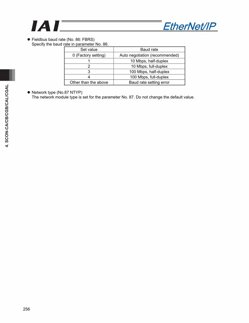
4. S
CO
N-C
A/C
B/C
GB
/CA
L/C
GA
L
256
Fieldbus baud rate (No. 86: FBRS) Specify the baud rate in parameter No. 86.
Set value Baud rate 0 (Factory setting) Auto negotiation (recommended)
1 10 Mbps, half-duplex 2 10 Mbps, full-duplex 3 100 Mbps, half-duplex 4 100 Mbps, full-duplex
Other than the above Baud rate setting error
Network type (No.87 NTYP) The network module type is set for the parameter No. 87. Do not change the default value.
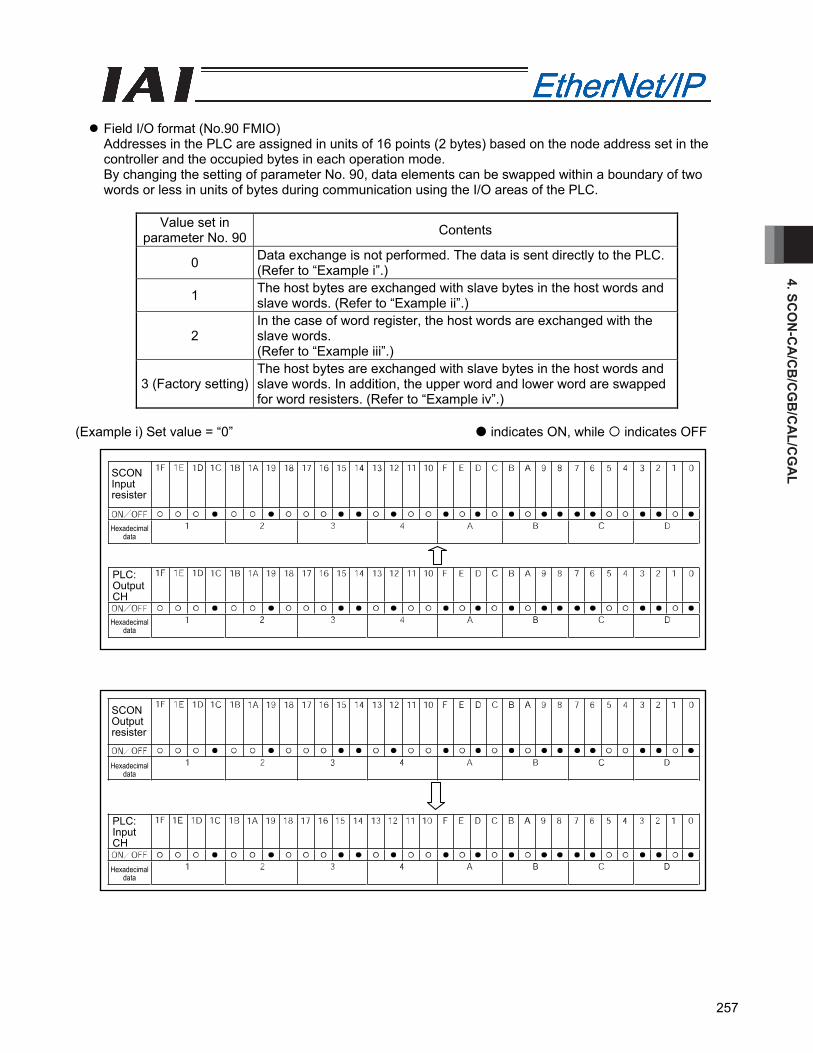
4. SCO
N-C
A/C
B/C
GB
/CA
L/CG
AL
257
Field I/O format (No.90 FMIO) Addresses in the PLC are assigned in units of 16 points (2 bytes) based on the node address set in the controller and the occupied bytes in each operation mode. By changing the setting of parameter No. 90, data elements can be swapped within a boundary of two words or less in units of bytes during communication using the I/O areas of the PLC.
Value set in
parameter No. 90 Contents
0 Data exchange is not performed. The data is sent directly to the PLC. (Refer to “Example i”.)
1 The host bytes are exchanged with slave bytes in the host words and slave words. (Refer to “Example ii”.)
2 In the case of word register, the host words are exchanged with the slave words. (Refer to “Example iii”.)
3 (Factory setting) The host bytes are exchanged with slave bytes in the host words and slave words. In addition, the upper word and lower word are swapped for word resisters. (Refer to “Example iv”.)
(Example i) Set value = “0” indicates ON, while indicates OFF
SCON Input resister
Hexadecimal data
PLC: Output CH
Hexadecimal data
SCON Output resister
Hexadecimal data
PLC: Input CH
Hexadecimal data
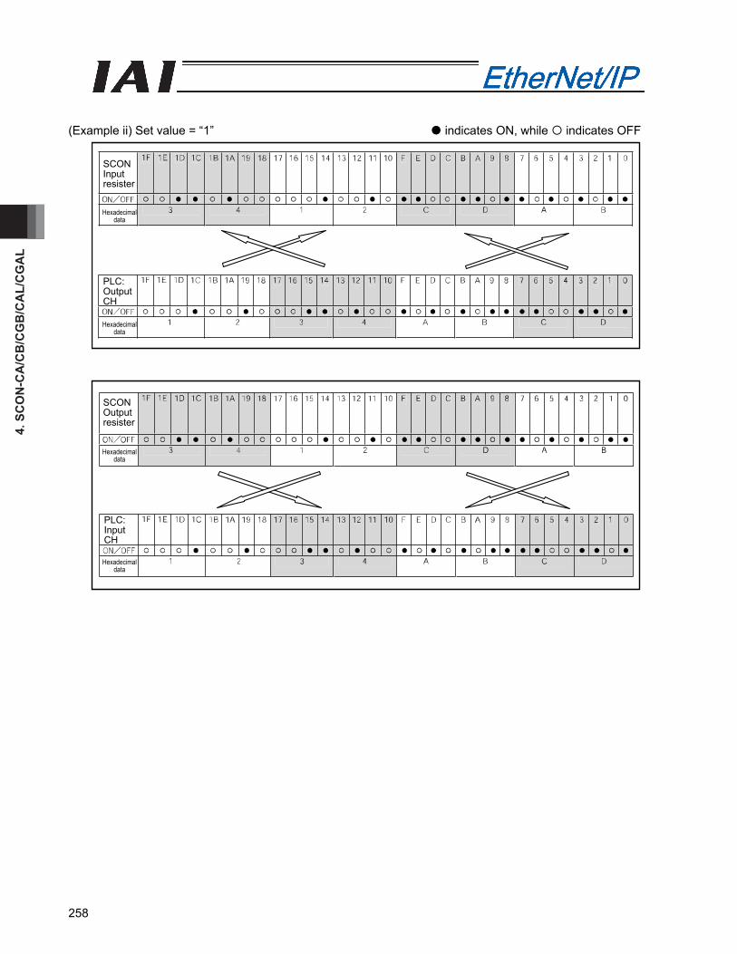
4. S
CO
N-C
A/C
B/C
GB
/CA
L/C
GA
L
258
(Example ii) Set value = “1” indicates ON, while indicates OFF
SCON Input resister
SCON Output resister
Hexadecimal data
PLC: Output CH
PLC: Input CH
Hexadecimal data
Hexadecimal data
Hexadecimal data
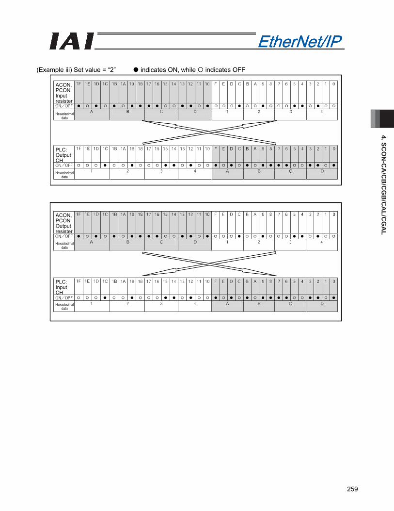
4. SCO
N-C
A/C
B/C
GB
/CA
L/CG
AL
259
(Example iii) Set value = “2” indicates ON, while indicates OFF
ACON, PCON Input resister
ACON, PCON Output resister
Hexadecimal data
PLC: Output CH
PLC: Input CH
Hexadecimal data
Hexadecimal data
Hexadecimal data
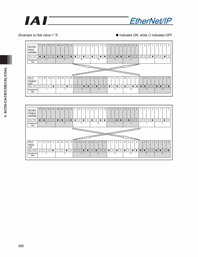
4. S
CO
N-C
A/C
B/C
GB
/CA
L/C
GA
L
260
(Example iv) Set value = “3” indicates ON, while indicates OFF
SCON Input resister
SCON Output resister
Hexadecimal data
PLC: Output CH
PLC: Input CH
Hexadecimal data
Hexadecimal data
Hexadecimal data
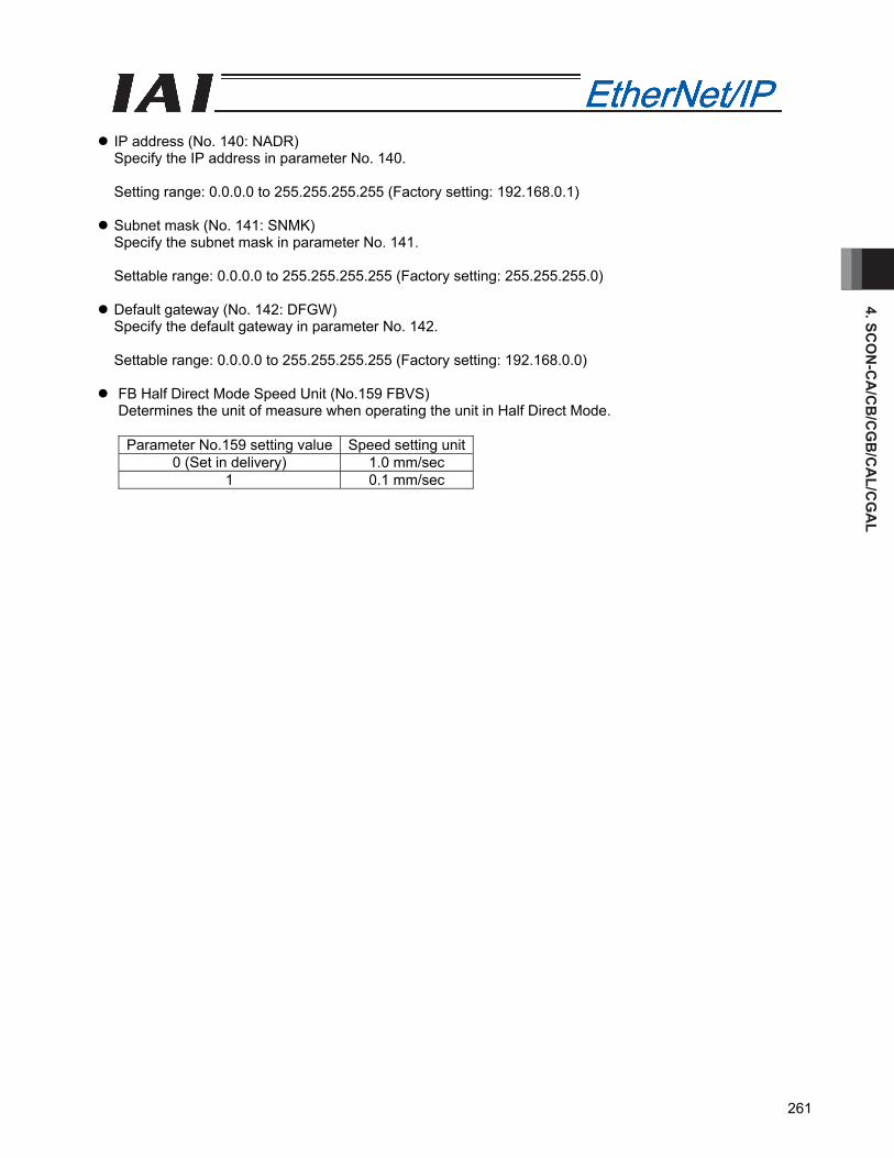
4. SCO
N-C
A/C
B/C
GB
/CA
L/CG
AL
261
IP address (No. 140: NADR) Specify the IP address in parameter No. 140. Setting range: 0.0.0.0 to 255.255.255.255 (Factory setting: 192.168.0.1)
Subnet mask (No. 141: SNMK) Specify the subnet mask in parameter No. 141. Settable range: 0.0.0.0 to 255.255.255.255 (Factory setting: 255.255.255.0)
Default gateway (No. 142: DFGW) Specify the default gateway in parameter No. 142. Settable range: 0.0.0.0 to 255.255.255.255 (Factory setting: 192.168.0.0)
FB Half Direct Mode Speed Unit (No.159 FBVS) Determines the unit of measure when operating the unit in Half Direct Mode.
Parameter No.159 setting value Speed setting unit0 (Set in delivery) 1.0 mm/sec
1 0.1 mm/sec

4. S
CO
N-C
A/C
B/C
GB
/CA
L/C
GA
L
262
4.10 Troubleshooting
Alarm messages and causes/actions When an alarm occurs, a corresponding simple alarm code is indicated by the completed position number bits (four bits of PM1 to PM8) in remote I/O mode 1, 2 or 3. In position/simple direct mode 1 or 2, this simple alarm code is output to the (n+4, n+5) bytes. In half direct mode 1, 2 or 3 or in the full direct mode, this alarm code is output to the (n+12, n+13) bytes [1] Check the alarm code using the monitor function of the PLC, etc., or connect the RC PC software or
other teaching tool and check the status monitor screen. [2] Search the alarm list in the operation manual for your controller to find the section corresponding to
the identified alarm code. [3] Take an appropriate action according to the explanation of the alarm code.
For the alarm codes listed below, take the corresponding actions:
Code Error name ID (*1)
RES(*2) Cause/action
0F2 Fieldbus module error 05 x Cause: A fieldbus module error has been
detected. Action: Check the applicable parameters.
0F3 Fieldbus module non-detection error 04 x
Cause: The module could not be detected. Action: Reconnect the power. If the problem
persists, please contact IAI. (*1) ID → Simple alarm code (*2) RES → Alarm can/cannot be reset O: Alarm can be reset / X: Alarm cannot be reset

5. Servo Press Type SCO
N-C
B/C
GB
263
Flat cable Communication
cable
5. Servo Press Type SCON-CB/CGB (Note) As CB and CGB Types possess the same functions, this manual describes them together as CB Type. 5.1 Operation Modes and Functions The operation modes described in the table below for SCON-CB Type applicable for EtherNet/IP are available to choose from for operation.
Operation modes and key functions
Key function Remote I/O mode Full function mode Number of occupied bytes 2 32 Operation by position data specification × ○ Direct speed/acceleration specification × ○ Current position reading × ○ Current speed reading × ○ Program number command operation ○ ○ Judgement result reading ○ ○ Current load data reading × ○ Overload level monitor × ○ Servo gain switching ○(*1) ○(*1)
(*1) One servo gain can be registered to one press program. [1] Remote I/O mode: In this mode, the actuator is operated by PIOs (24 V I/Os) via EtherNet/IP communication.
Number of occupied bytes: 2 bytes
[2] Full function mode: It is the system to support all the features such as movement by direct indication or
current load reading in addition to those for servo press such as startup of press program or judgment result reading. Number of occupied bytes: 32 bytes
EtherNet/IP connection
SCON-CB not supporting EtherNet/IP
PIO connection
SCON-CB supporting EtherNet/IP
Command Program No.: 1
Current Load Data: 10.0N Current Speed: 10mm/s Judgement Result: OK
PLC
SCON-CB not supporting EtherNet/IP
Actuator
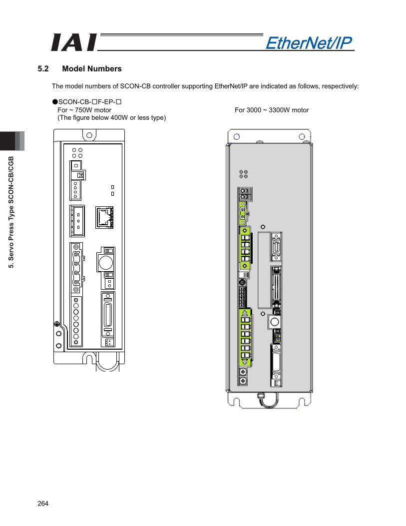
5. S
ervo
Pre
ss T
ype
SCO
N-C
B/C
GB
264
5.2 Model Numbers
The model numbers of SCON-CB controller supporting EtherNet/IP are indicated as follows, respectively:
●SCON-CB-□F-EP-□For ~ 750W motor For 3000 ~ 3300W motor (The figure below 400W or less type)
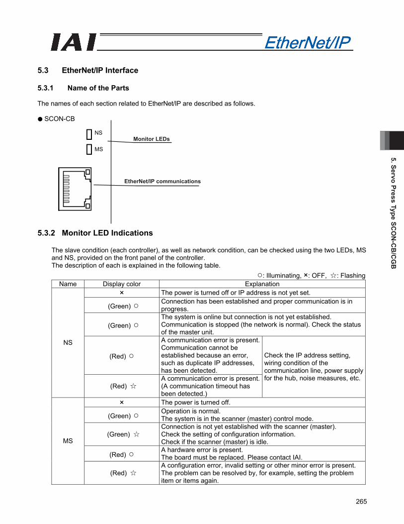
5. Servo Press Type SCO
N-C
B/C
GB
265
Monitor LEDs
EtherNet/IP communications
5.3 EtherNet/IP Interface
5.3.1 Name of the Parts
The names of each section related to EtherNet/IP are described as follows. ● SCON-CB
5.3.2 Monitor LED Indications
The slave condition (each controller), as well as network condition, can be checked using the two LEDs, MS and NS, provided on the front panel of the controller. The description of each is explained in the following table.
○: Illuminating, ×: OFF, ☆: Flashing Name Display color Explanation
× The power is turned off or IP address is not yet set.
(Green) ○ Connection has been established and proper communication is in progress.
(Green) ○ The system is online but connection is not yet established. Communication is stopped (the network is normal). Check the status of the master unit.
(Red) ○
A communication error is present. Communication cannot be established because an error, such as duplicate IP addresses, has been detected.
NS
(Red) ☆ A communication error is present. (A communication timeout has been detected.)
Check the IP address setting, wiring condition of the communication line, power supply for the hub, noise measures, etc.
× The power is turned off.
(Green) ○ Operation is normal. The system is in the scanner (master) control mode.
(Green) ☆ Connection is not yet established with the scanner (master). Check the setting of configuration information. Check if the scanner (master) is idle.
(Red) ○ A hardware error is present. The board must be replaced. Please contact IAI.
MS
(Red) ☆ A configuration error, invalid setting or other minor error is present. The problem can be resolved by, for example, setting the problem item or items again.
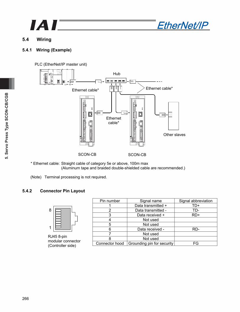
5. S
ervo
Pre
ss T
ype
SCO
N-C
B/C
GB
266
5.4 Wiring
5.4.1 Wiring (Example)
* Ethernet cable: Straight cable of category 5e or above, 100m max
(Aluminum tape and braided double-shielded cable are recommended.)
(Note) Terminal processing is not required. 5.4.2 Connector Pin Layout
Pin number Signal name Signal abbreviation 1 Data transmitted + TD+ 2 Data transmitted - TD- 3 Data received + RD+ 4 Not used 5 Not used 6 Data received - RD- 7 Not used 8 Not used
Connector hood Grounding pin for security FG
RJ45 8-pin modular connector (Controller side)
8
1
PLC (EtherNet/IP master unit)
Ethernet cable*
Ethernet cable* Ethernet cable*
Other slaves
Hub
SCON-CB SCON-CB
5. Servo Press Type SCO
N-C
B/C
GB
267
5.5 Setting
Using the teaching tool, set controller parameters. Set the mode toggle switch on the front panel of the controller to “MANU” side. Refer to the instruction manual for each teaching tool for the applicable version of the teaching tool that can be applied to EtherNet/IP.
5.5.1 Operation Mode Selecting
Set parameter No. 84 “FMOD: Field bus operation mode.” [Refer to 5.9 EtherNet/IP Related Parameters.]
Set value Operation mode Number of occupied bytes
0 (Factory setting) Remote I/O mode 2
1 Full function mode 32 * Entering any value except for the ones described above will cause an “Excessive Input Value Error”.
5.5.2 Setting the Baud Rate
Set parameter No. 86, “FBRS: Fieldbus baud rate.” Set value Baud rate
0 (Factory setting) Auto negotiation (recommended) 1 10 Mbps, half-duplex 2 10 Mbps, full-duplex 3 100 Mbps, half-duplex 4 100 Mbps, full-duplex
Other than the above Baud rate setting error
5.5.3 Setting the IP Address
Set parameter No. 140, “IPAD: IP address.” [Refer to 5.9, “EtherNet/IP Parameters.”] Settable Range: 0.0.0.0 to 255.255.255.255 (It is set to “192.168.0.1” when the machine is delivered from the factory.) (Note 1) Exercise caution to avoid IP address duplication.
For details, refer to the operation manuals of the master unit and PLC in which in the master unit is installed.
5.5.4 Setting the Subnet Mask
Set parameter No. 141, “SNMK: Subnet mask.” Set the same value you have set in the master unit and other slaves (on the same network). [Refer to 5.9, “EtherNet/IP Parameters.”] Settable range: 0.0.0.0 to 255.255.255.255 (The factory setting is 255.255.255.0.)
5. S
ervo
Pre
ss T
ype
SCO
N-C
B/C
GB
268
5.5.5 Setting the Default Gateway
If necessary, set parameter No. 142, “DFGW: Default gateway.” [Refer to 5.9, “EtherNet/IP Parameters.”] Settable range: 0.0.0.0 to 255.255.255.255 (The factory setting is 192.168.0.0.)
(Note) After the parameter setting, turn on the power to the controller again and return the mode toggle switch on the front of the controller to “AUTO” side. When the switch is set to “MANU”, the operation using PLC is not available.
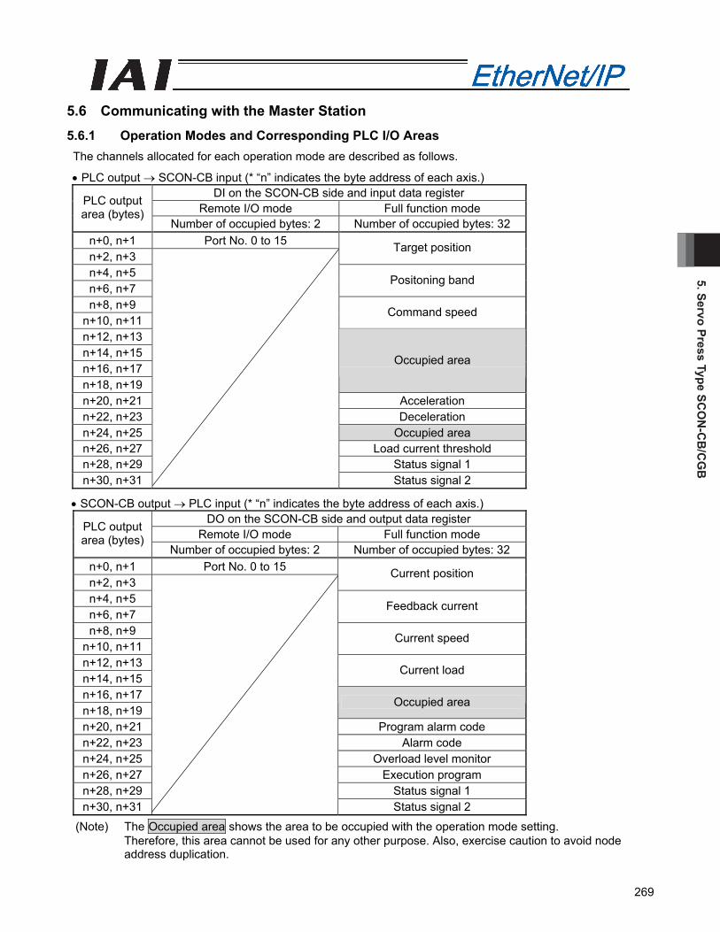
5. Servo Press Type SCO
N-C
B/C
GB
269
5.6 Communicating with the Master Station
5.6.1 Operation Modes and Corresponding PLC I/O Areas
The channels allocated for each operation mode are described as follows.
• PLC output → SCON-CB input (* “n” indicates the byte address of each axis.) DI on the SCON-CB side and input data register
Remote I/O mode Full function mode PLC output area (bytes)
Number of occupied bytes: 2 Number of occupied bytes: 32 n+0, n+1 Port No. 0 to 15 n+2, n+3
Target position
n+4, n+5 n+6, n+7
Positoning band
n+8, n+9 n+10, n+11
Command speed
n+12, n+13 n+14, n+15 n+16, n+17 n+18, n+19
Occupied area
n+20, n+21 Acceleration n+22, n+23 Deceleration n+24, n+25 Occupied area n+26, n+27 Load current threshold n+28, n+29 Status signal 1 n+30, n+31
Status signal 2
• SCON-CB output → PLC input (* “n” indicates the byte address of each axis.) DO on the SCON-CB side and output data register
Remote I/O mode Full function mode PLC output area (bytes)
Number of occupied bytes: 2 Number of occupied bytes: 32 n+0, n+1 Port No. 0 to 15 n+2, n+3
Current position
n+4, n+5 n+6, n+7
Feedback current
n+8, n+9 n+10, n+11
Current speed
n+12, n+13 n+14, n+15
Current load
n+16, n+17 n+18, n+19
Occupied area
n+20, n+21 Program alarm code n+22, n+23 Alarm code n+24, n+25 Overload level monitor n+26, n+27 Execution program n+28, n+29 Status signal 1 n+30, n+31
Status signal 2
(Note) The Occupied area shows the area to be occupied with the operation mode setting. Therefore, this area cannot be used for any other purpose. Also, exercise caution to avoid node address duplication.

5. S
ervo
Pre
ss T
ype
SCO
N-C
B/C
GB
270
5.6.2 Remote I/O Mode (Number of Occupied Bytes: 2)
This is the operation mode with the fieldbus communication indicate each I/O signal is ON/OFF instead of PIO (Actuial 24V I/O). Create a press program on a PC software for RC. The robot cylinder's effective main functions that can be controlled using this mode, are as shown in the following table. Operation modes and key functions
Key function ○: Directly controls×: Invalid
Operation by position data specification × Direct speed/acceleration specification × Current position reading × Current speed reading × Program number command operation ○ Judgement result reading ○ Current load data reading × Overload level monitor × Servo gain switching ○ (*1)
(*1) One servo gain can be registered to one press program. (1) PLC address configuration (* “n” indicates the first address of each axis.)
Parameter No. 84
SCON-CB side DI (Port No.)
PLC side output address (bytes)
SCON-CB side DO (Port No.)
PLC side input address (bytes)
0 0 to 15 n+0, n+1 0 to 15 n+0, n+1
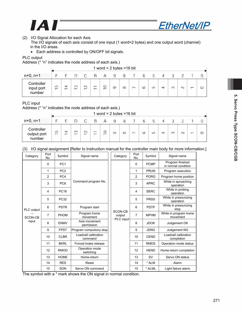
5. Servo Press Type SCO
N-C
B/C
GB
271
(2) I/O Signal Allocation for each Axis The I/O signals of each axis consist of one input (1 word=2 bytes) and one output word (channel)
in the I/O areas. • Each address is controlled by ON/OFF bit signals.
PLC output Address (* “n” indicates the node address of each axis.) PLC input Address (* “n” indicates the node address of each axis.) (3) I/O signal assignment [Refer to Instruction manual for the controller main body for more information.]
Category Port No. Symbol Signal name Category Port
No. Symbol Signal name
0 PC1 0 PCMP Program finished in normal condition
1 PC2 1 PRUN Program execution
2 PC4 2 PORG Program home position
3 PC8 3 APRC While in aproaching operation
4 PC16 4 SERC While in probing operation
5 PC32
Command program No.
5 PRSS While in pressurizing operation
6 PSTR Program start 6 PSTP While in pressurizing stop
7 PHOM Program home movement 7 MPHM While in program home
movement
8 ENMV Axis movement permission 8 JDOK Judgement OK
9 FPST Program compulsory stop 9 JDNG Judgement NG
10 CLBR Loadcell calibration command 10 CEND Loadcell calibration
completion 11 BKRL Forced brake release 11 RMDS Operation mode status
12 RMOD Operation mode switching 12 HEND Home-return completion
13 HOME Home-return 13 SV Servo ON status
14 RES Reset 14 * ALM Alarm
PLC output →
SCON-CB input
15 SON Servo ON command
SCON-CBoutput
→PLC input
15 * ALML Light failure alarm
The symbol with a * mark shows the ON signal in normal condition.
n+0、n+1n+0、n+1
Controller input port number
1 word = 2 bytes =16 bit
n+0, n+1
n+0、n+1
Controller output port
number
n+0, n+1
1 word = 2 bytes =16 bit

5. S
ervo
Pre
ss T
ype
SCO
N-C
B/C
GB
272
5.6.3 Full Function Mode(Number of Occupied Bytes: 32)
It is the mode operation system to conduct all the servo press features in fieldbus communication. Set each value in the input and output areas. The robot cylinder's effective main functions that can be controlled using this mode, are as shown in the following table. Operation modes and key functions
Key function ○: Directly controls×: Invalid
Operation by position data specification ○ Direct speed/acceleration specification ○ Current position reading ○ Current speed reading ○ Program number command operation ○ Judgement result reading ○ Current load reading ○ Overload level monitor ○ Servo gain switching ○(*1)
(*1) One servo gain can be registered to one press program. (1) PLC address configuration (* “n” indicates the first address of each axis.)
Parameter No. 84
SCON-CB side input side resister
PLC side output address
(bytes)
SCON-CB side output side resister
PLC side input address
(bytes) n+0, n+1 n+0, n+1 Target position n+2, n+3
Current position n+2, n+3
n+4, n+5 n+4, n+5 Positioning band n+6, n+7
Feedback current n+6, n+7
n+8, n+9 n+8, n+9 Speed n+10, n+11
Current speed n+10, n+11
n+12, n+13 n+12, n+13 Occupied area n+14, n+15
Current load data n+14, n+15
n+16, n+17 n+16, n+17 Occupied area n+18, n+19
Occupied area n+18, n+19
Acceleration n+20, n+21 Program alarm code n+20, n+21 Deceleration n+22, n+23 Alarm code n+22, n+23
Occupied area n+24, n+25 Overload level monitor n+24, n+25 Command program No. n+26, n+27 Execution program No. n+26, n+27
Status signal 1 n+28, n+29 Status signal 1 n+28, n+29
1
Status signal 2 n+30, n+31 Status signal 2 n+30, n+31 (Note) The Occupied area shows the area to be occupied with the operation mode setting.
Therefore, this area cannot be used for any other purpose. Also, exercise caution to avoid node address duplication.
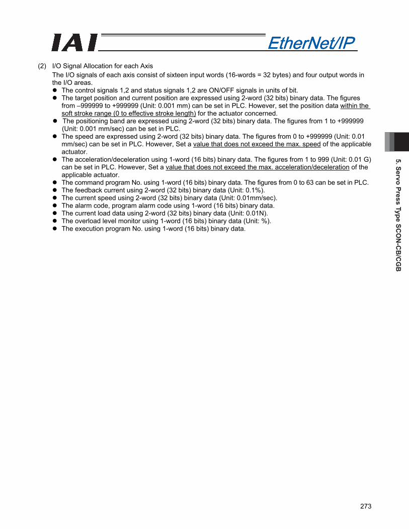
5. Servo Press Type SCO
N-C
B/C
GB
273
(2) I/O Signal Allocation for each Axis
The I/O signals of each axis consist of sixteen input words (16-words = 32 bytes) and four output words in the I/O areas.
The control signals 1,2 and status signals 1,2 are ON/OFF signals in units of bit. The target position and current position are expressed using 2-word (32 bits) binary data. The figures
from –999999 to +999999 (Unit: 0.001 mm) can be set in PLC. However, set the position data within the soft stroke range (0 to effective stroke length) for the actuator concerned.
The positioning band are expressed using 2-word (32 bits) binary data. The figures from 1 to +999999 (Unit: 0.001 mm/sec) can be set in PLC.
The speed are expressed using 2-word (32 bits) binary data. The figures from 0 to +999999 (Unit: 0.01 mm/sec) can be set in PLC. However, Set a value that does not exceed the max. speed of the applicable actuator.
The acceleration/deceleration using 1-word (16 bits) binary data. The figures from 1 to 999 (Unit: 0.01 G) can be set in PLC. However, Set a value that does not exceed the max. acceleration/deceleration of the applicable actuator.
The command program No. using 1-word (16 bits) binary data. The figures from 0 to 63 can be set in PLC. The feedback current using 2-word (32 bits) binary data (Unit: 0.1%). The current speed using 2-word (32 bits) binary data (Unit: 0.01mm/sec). The alarm code, program alarm code using 1-word (16 bits) binary data. The current load data using 2-word (32 bits) binary data (Unit: 0.01N). The overload level monitor using 1-word (16 bits) binary data (Unit: %). The execution program No. using 1-word (16 bits) binary data.
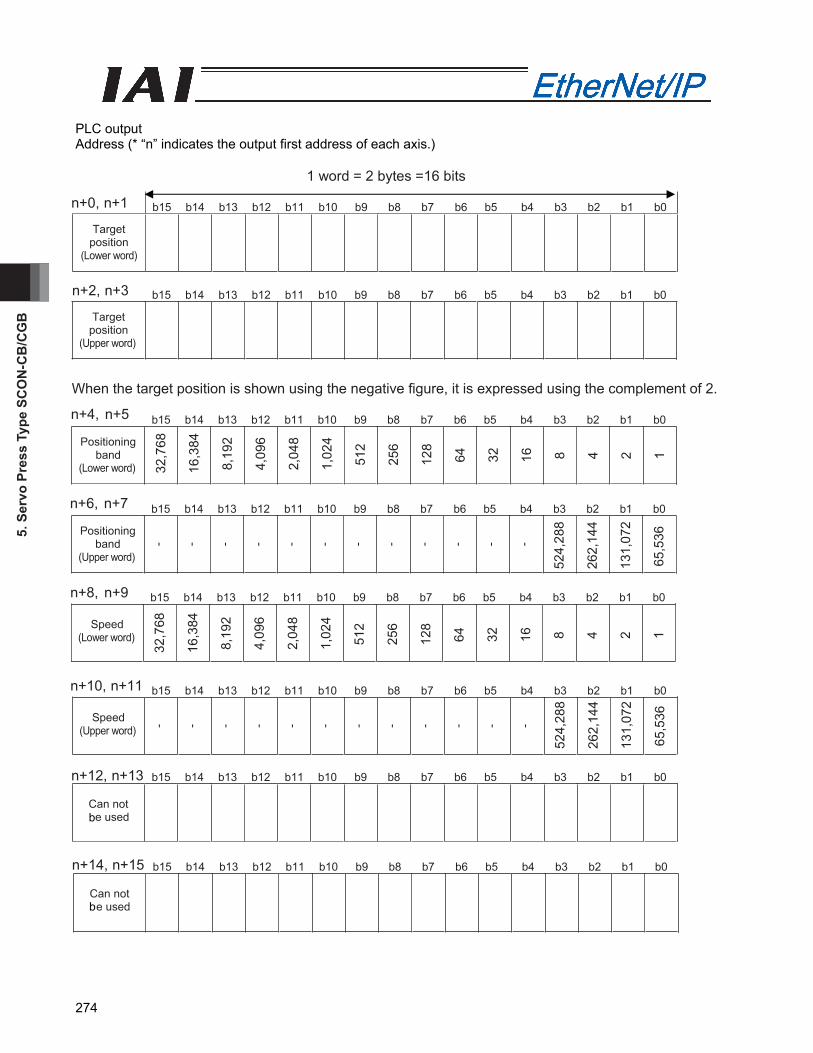
5. S
ervo
Pre
ss T
ype
SCO
N-C
B/C
GB
274
PLC output Address (* “n” indicates the output first address of each axis.)

5. Servo Press Type SCO
N-C
B/C
GB
275
Address (* “n” indicates the output first address of each axis.)
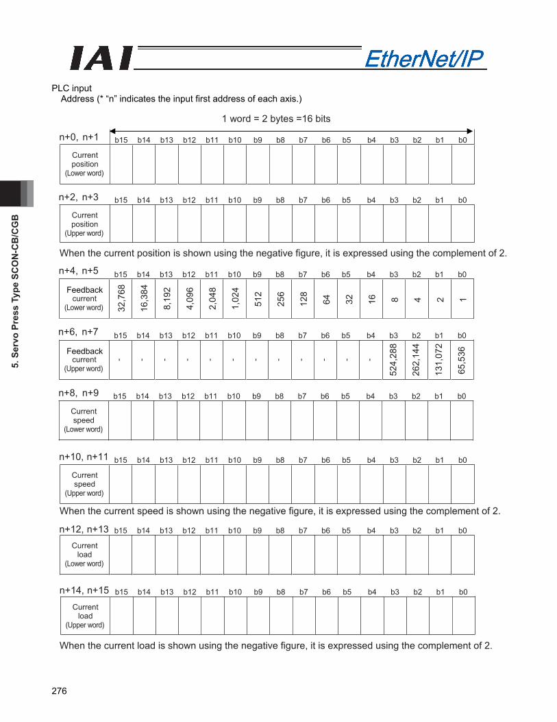
5. S
ervo
Pre
ss T
ype
SCO
N-C
B/C
GB
276
PLC input Address (* “n” indicates the input first address of each axis.)
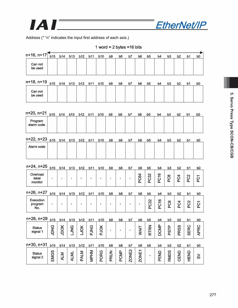
5. Servo Press Type SCO
N-C
B/C
GB
277
Address (* “n” indicates the input first address of each axis.)
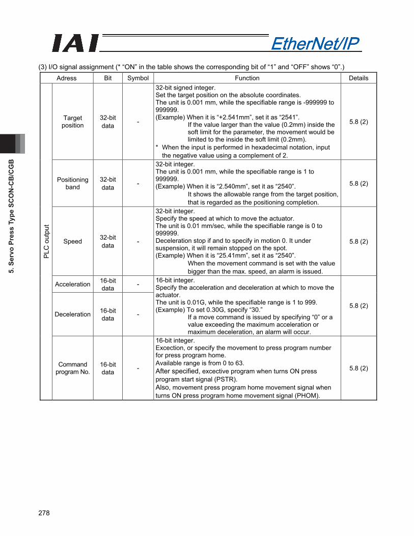
5. S
ervo
Pre
ss T
ype
SCO
N-C
B/C
GB
278
(3) I/O signal assignment (* “ON” in the table shows the corresponding bit of “1” and “OFF” shows “0”.)
Adress Bit Symbol Function Details
Target position
32-bit data -
32-bit signed integer. Set the target position on the absolute coordinates. The unit is 0.001 mm, while the specifiable range is -999999 to 999999. (Example) When it is “+2.541mm”, set it as “2541”.
If the value larger than the value (0.2mm) inside the soft limit for the parameter, the movement would be limited to the inside the soft limit (0.2mm).
* When the input is performed in hexadecimal notation, input the negative value using a complement of 2.
5.8 (2)
Positioning band
32-bit data -
32-bit integer. The unit is 0.001 mm, while the specifiable range is 1 to 999999. (Example) When it is “2.540mm”, set it as “2540”.
It shows the allowable range from the target position, that is regarded as the positioning completion.
5.8 (2)
Speed 32-bit data -
32-bit integer. Specify the speed at which to move the actuator. The unit is 0.01 mm/sec, while the specifiable range is 0 to 999999. Deceleration stop if and to specify in motion 0. It under suspension, it will remain stopped on the spot. (Example) When it is “25.41mm”, set it as “2540”.
When the movement command is set with the value bigger than the max. speed, an alarm is issued.
5.8 (2)
Acceleration 16-bit data -
Deceleration 16-bit data -
16-bit integer. Specify the acceleration and deceleration at which to move the actuator. The unit is 0.01G, while the specifiable range is 1 to 999. (Example) To set 0.30G, specify “30.”
If a move command is issued by specifying “0” or a value exceeding the maximum acceleration or maximum deceleration, an alarm will occur.
5.8 (2)
PLC
out
put
Command program No.
16-bit data -
16-bit integer. Excection, or specify the movement to press program number for press program home. Available range is from 0 to 63. After specified, excective program when turns ON press program start signal (PSTR). Also, movement press program home movement signal when turns ON press program home movement signal (PHOM).
5.8 (2)
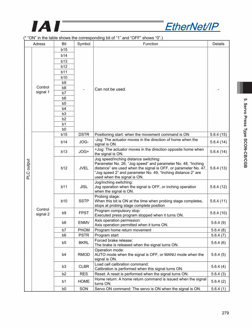
5. Servo Press Type SCO
N-C
B/C
GB
279
(* “ON” in the table shows the corresponding bit of “1” and “OFF” shows “0”.) Adress Bit Symbol Function Details
b15 b14 b13 b12 b11 b10 b9 b8 b7 b6 b5 b4 b3 b2 b1
Control signal 1
b0
- Can not be used. -
b15 DSTR Positioning start: when the movement command is ON 5.6.4 (15)
b14 JOG- -Jog: The actuator moves in the direction of home when the signal is ON. 5.6.4 (14)
b13 JOG+ +Jog: The actuator moves in the direction opposite home when the signal is ON. 5.6.4 (14)
b12 JVEL
Jog speed/inching distance switching: Parameter No. 26, “Jog speed” and parameter No. 48, “Inching distance” are used when the signal is OFF, or parameter No. 47, “Jog speed 2” and parameter No. 49, “Inching distance 2” are used when the signal is ON.
5.6.4 (13)
b11 JISL Jog/inching switching: Jog operation when the signal is OFF, or inching operation when the signal is ON.
5.6.4 (12)
b10 SSTP Probing stage: When this bit is ON at the time when probing stage completes, stops at probing stage complete position
5.6.4 (11)
b9 FPST Program compulsory stop: Executed press program stopped when it turns ON. 5.6.4 (10)
b8 ENMV Axis operation permission: Axis operation permitted when it turns ON. 5.6.4 (9)
b7 PHOM Program home return movement 5.6.4 (8)b6 PSTR Program start 5.6.4 (7)
b5 BKRL Forced brake release: The brake is released when the signal turns ON. 5.6.4 (6)
b4 RMOD Operation mode: AUTO mode when the signal is OFF, or MANU mode when the signal is ON.
5.6.4 (5)
b3 CLBR Load cell calibration command: Calibration is performed when this signal turns ON. 5.6.4 (4)
b2 RES Reset: A reset is performed when the signal turns ON. 5.6.4 (3)
b1 HOME Home return: A home return command is issued when the signal turns ON. 5.6.4 (2)
PLC
out
put
Control signal 2
b0 SON Servo ON command: The servo is ON when the signal is ON. 5.6.4 (1)
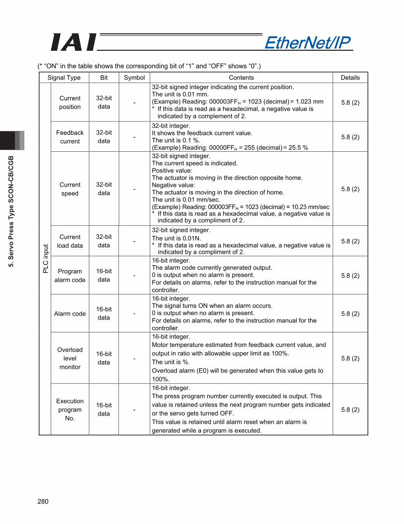
5. S
ervo
Pre
ss T
ype
SCO
N-C
B/C
GB
280
(* “ON” in the table shows the corresponding bit of “1” and “OFF” shows “0”.)
Signal Type Bit Symbol Contents Details
Current position
32-bit data -
32-bit signed integer indicating the current position. The unit is 0.01 mm. (Example) Reading: 000003FFH = 1023 (decimal) = 1.023 mm * If this data is read as a hexadecimal, a negative value is
indicated by a complement of 2.
5.8 (2)
Feedback current
32-bit data -
32-bit integer. It shows the feedback current value. The unit is 0.1 %. (Example) Reading: 00000FFH = 255 (decimal) = 25.5 %
5.8 (2)
Current speed
32-bit data -
32-bit signed integer. The current speed is indicated. Positive value: The actuator is moving in the direction opposite home. Negative value: The actuator is moving in the direction of home. The unit is 0.01 mm/sec. (Example) Reading: 000003FFH = 1023 (decimal) = 10.23 mm/sec* If this data is read as a hexadecimal value, a negative value is
indicated by a compliment of 2.
5.8 (2)
Current load data
32-bit data -
32-bit signed integer. The unit is 0.01N. * If this data is read as a hexadecimal value, a negative value is
indicated by a compliment of 2. 5.8 (2)
Program alarm code
16-bit data
-
16-bit integer. The alarm code currently generated output. 0 is output when no alarm is present. For details on alarms, refer to the instruction manual for the controller.
5.8 (2)
Alarm code 16-bit data
-
16-bit integer. The signal turns ON when an alarm occurs. 0 is output when no alarm is present. For details on alarms, refer to the instruction manual for the controller.
5.8 (2)
Overload level
monitor
16-bit data -
16-bit integer. Motor temperature estimated from feedback current value, and output in ratio with allowable upper limit as 100%. The unit is %. Overload alarm (E0) will be generated when this value gets to 100%.
5.8 (2)
PLC
inpu
t
Execution program
No.
16-bit data -
16-bit integer. The press program number currently executed is output. This value is retained unless the next program number gets indicated or the servo gets turned OFF. This value is retained until alarm reset when an alarm is generated while a program is executed.
5.8 (2)

5. Servo Press Type SCO
N-C
B/C
GB
281
(* “ON” in the table shows the corresponding bit of “1” and “OFF” shows “0”.) Signal Type Bit Symbol Contents Details
b15 JDNG Overall Judgment NG: Turns ON when overall judgment was made for load and position (distance) as a NG.
5.6.4 (31)
b14 JDOK Overall Judgment OK: Turns ON when Overall judgment was made for load and position (distance) as a OK.
5.6.4 (31)
b13 LJNG Load judgement NG: Turns ON when load for pressing operation judged NG. 5.6.4 (30)
b12 LJOK Load judgement OK: Turns ON when load for pressing operation judged OK. 5.6.4 (30)
b11 PJNG Position (distance) judgement OK: Turns ON when load for pressing operation position (distance) judged NG.
5.6.4 (30)
b10 PJOK Position (distance) judgement NG: Turns ON when load for pressing operation position (distance) judged OK.
5.6.4 (30)
b9 - b8 - b7 -
Can not be used. -
b6 WAIT Press program standby: Turns ON in standby status after press program finished in normal condition.
5.6.4 (29)
b5 RTRN Returned during the operation: Turns ON during returning stage. 5.6.4 (28)
b4 DCMP While in decompressing operation: Turns ON during decompressing stage. 5.6.4 (27)
b3 PSTP Pressurize during the stop: Turns ON during stop in pressurizing stage. 5.6.4 (26)
b2 PRSS While in pressurizing operation: Turns ON while pressurizing operation executed in pressurizing stage.
5.6.4 (25)
b1 SERC While in probing operation: Turns ON when probing stage executed. 5.6.4 (24)
Status signal 1
b0 APRC While in approaching the operation: Turns ON when approaching stage executed. 5.6.4 (23)
b15 EMGS Emergency stop: An emergency stop is being executed when the signal is ON. 5.6.4 (22)
b14 ALM Alarm: The signal turns ON when an alarm occurs. 5.6.4 (21)
b13 ALML Light failure alarm: The signal turns ON when an light failure alarm occurs. 5.6.4 (20)
b12 PALM Program alarm: The signal turns ON when an program alarm occurs. 5.6.4 (19)
b11 MPHM Program home return during the movement: Turns ON while in movement to home position set to each press program.
5.6.4 (8)
b10 PORG Program home position: Turns ON while in achieve to reach to home position set to each press program.
5.6.4 (8)
PLC
inpu
t
Status signal 2
b9 PRUN Press program excecuted: Turns ON when press program executed. 5.6.4 (7)
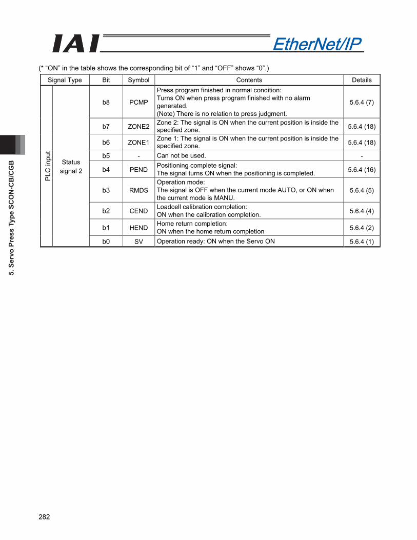
5. S
ervo
Pre
ss T
ype
SCO
N-C
B/C
GB
282
(* “ON” in the table shows the corresponding bit of “1” and “OFF” shows “0”.)
Signal Type Bit Symbol Contents Details
PLC
inpu
t
Statussignal 2
b8 PCMP
Press program finished in normal condition:Turns ON when press program finished with no alarm generated.(Note) There is no relation to press judgment.
5.6.4 (7)
b7 ZONE2 Zone 2: The signal is ON when the current position is inside the specified zone. 5.6.4 (18)
b6 ZONE1 Zone 1: The signal is ON when the current position is inside the specified zone. 5.6.4 (18)
b5 - Can not be used. -
b4 PEND Positioning complete signal: The signal turns ON when the positioning is completed. 5.6.4 (16)
b3 RMDSOperation mode: The signal is OFF when the current mode AUTO, or ON when the current mode is MANU.
5.6.4 (5)
b2 CEND Loadcell calibration completion:ON when the calibration completion. 5.6.4 (4)
b1 HEND Home return completion:ON when the home return completion 5.6.4 (2)
b0 SV Operation ready: ON when the Servo ON 5.6.4 (1)
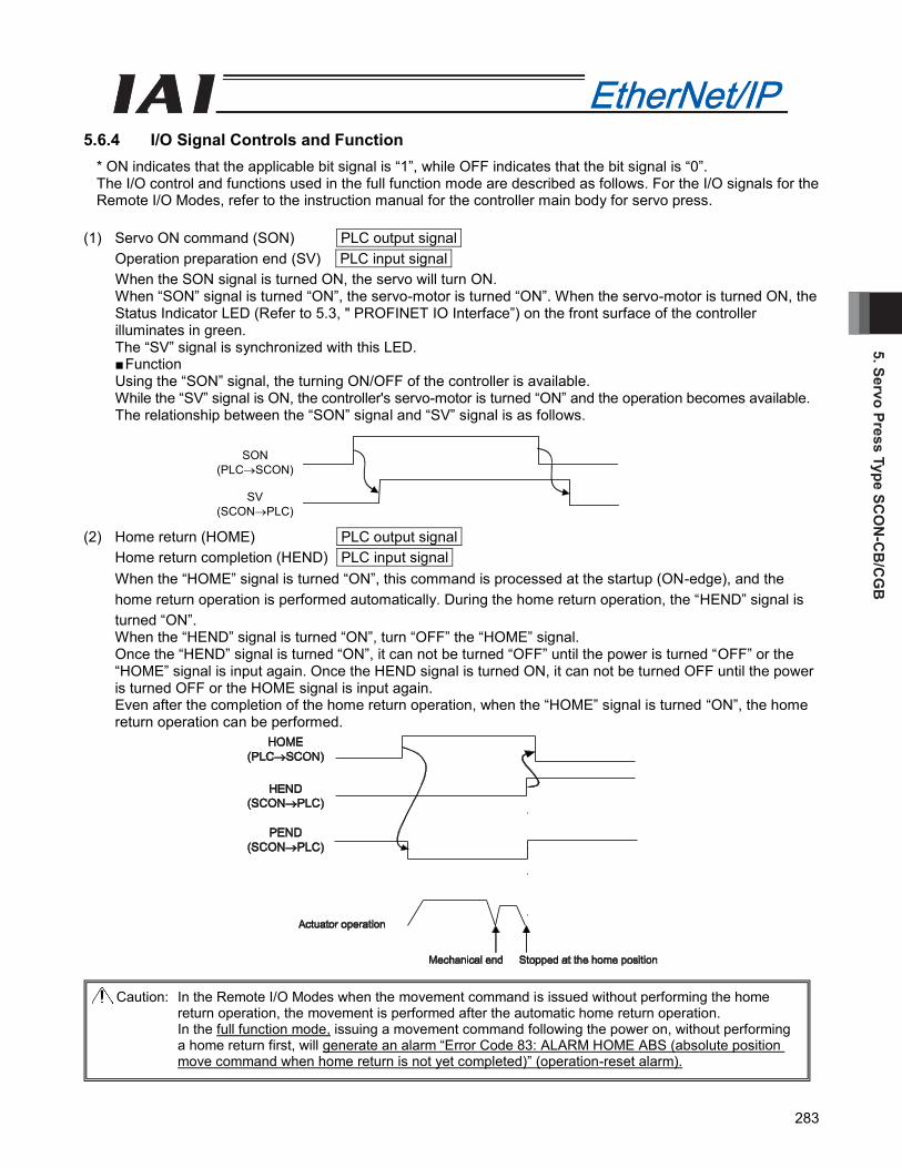
5. Servo Press Type SCO
N-C
B/C
GB
283
5.6.4 I/O Signal Controls and Function * ON indicates that the applicable bit signal is “1”, while OFF indicates that the bit signal is “0”.The I/O control and functions used in the full function mode are described as follows. For the I/O signals for the Remote I/O Modes, refer to the instruction manual for the controller main body for servo press.
(1) Servo ON command (SON) PLC output signalOperation preparation end (SV) PLC input signalWhen the SON signal is turned ON, the servo will turn ON. When “SON” signal is turned “ON”, the servo-motor is turned “ON”. When the servo-motor is turned ON, the Status Indicator LED (Refer to 5.3, " PROFINET IO Interface”) on the front surface of the controller illuminates in green. The “SV” signal is synchronized with this LED. ■ Function Using the “SON” signal, the turning ON/OFF of the controller is available.While the “SV” signal is ON, the controller's servo-motor is turned “ON” and the operation becomes available.The relationship between the “SON” signal and “SV” signal is as follows.
(2) Home return (HOME) PLC output signalHome return completion (HEND) PLC input signalWhen the “HOME” signal is turned “ON”, this command is processed at the startup (ON-edge), and the home return operation is performed automatically. During the home return operation, the “HEND” signal is turned “ON”.When the “HEND” signal is turned “ON”, turn “OFF” the “HOME” signal.Once the “HEND” signal is turned “ON”, it can not be turned “OFF” until the power is turned “OFF” or the “HOME” signal is input again. Once the HEND signal is turned ON, it can not be turned OFF until the power is turned OFF or the HOME signal is input again. Even after the completion of the home return operation, when the “HOME” signal is turned “ON”, the home return operation can be performed.
SON(PLCSCON)
SV(SCONPLC)
Caution: In the Remote I/O Modes when the movement command is issued without performing the home return operation, the movement is performed after the automatic home return operation.In the full function mode, issuing a movement command following the power on, without performing a home return first, will generate an alarm “Error Code 83: ALARM HOME ABS (absolute position move command when home return is not yet completed)” (operation-reset alarm).
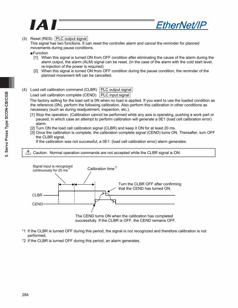
5. S
ervo
Pre
ss T
ype
SCO
N-C
B/C
GB
284
(3) Reset (RES) PLC output signal
This signal has two functions. It can reset the controller alarm and cancel the reminder for planned movements during pause conditions. ■ Function
[1] When this signal is turned ON from OFF condition after eliminating the cause of the alarm during the alarm output, the alarm (ALM) signal can be reset. (In the case of the alarm with the cold start level, re-injection of the power is required)
[2] When this signal is turned ON from OFF condition during the pause condition, the reminder of the planned movement left can be cancelled.
(4) Load cell calibration command (CLBR) PLC output signal
Load cell calibration complete (CEND) PLC input signal The factory setting for the load cell is 0N when no load is applied. If you want to use the loaded condition as the reference (0N), perform the following calibration. Also perform this calibration in other conditions as necessary (such as during readjustment, inspection, etc.). [1] Stop the operation. (Calibration cannot be performed while any axis is operating, pushing a work part or
paused, in which case an attempt to perform calibration will generate a 0E1 (load cell calibration error) alarm.
[2] Turn ON the load cell calibration signal (CLBR) and keep it ON for at least 20 ms. [3] Once the calibration is complete, the calibration complete signal (CEND) turns ON. Thereafter, turn OFF
the CLBR signal. If the calibration was not successful, a 0E1: (load cell calibration error) alarm generates.
Caution: Normal operation commands are not accepted while the CLBR signal is ON.
*1 If the CLBR is turned OFF during this period, the signal is not recognized and therefore calibration is not
performed. *2 If the CLBR is turned OFF during this period, an alarm generates.
Signal input is recognized continuously for 20 ms*1 Calibration time*2
Turn the CLBR OFF after confirming that the CEND has turned ON.
The CEND turns ON when the calibration has completed successfully. If the CLBR is OFF, the CEND remains OFF.
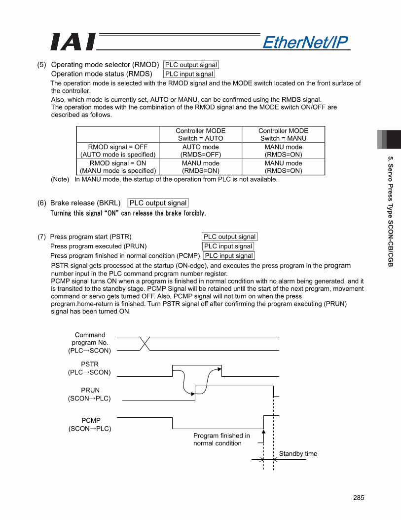
5. Servo Press Type SCO
N-C
B/C
GB
285
(5) Operating mode selector (RMOD) PLC output signal
Operation mode status (RMDS) PLC input signal The operation mode is selected with the RMOD signal and the MODE switch located on the front surface of the controller. Also, which mode is currently set, AUTO or MANU, can be confirmed using the RMDS signal. The operation modes with the combination of the RMOD signal and the MODE switch ON/OFF are described as follows.
Controller MODE Switch = AUTO
Controller MODE Switch = MANU
RMOD signal = OFF (AUTO mode is specified)
AUTO mode (RMDS=OFF)
MANU mode (RMDS=ON)
RMOD signal = ON (MANU mode is specified)
MANU mode (RMDS=ON)
MANU mode (RMDS=ON)
(Note) In MANU mode, the startup of the operation from PLC is not available. (6) Brake release (BKRL) PLC output signal
Turning this signal “ON” can release the brake forcibly. (7) Press program start (PSTR) PLC output signal
Press program executed (PRUN) PLC input signal Press program finished in normal condition (PCMP) PLC input signal
PSTR signal gets processed at the startup (ON-edge), and executes the press program in the program number input in the PLC command program number register. PCMP signal turns ON when a program is finished in normal condition with no alarm being generated, and it is transited to the standby stage. PCMP Signal will be retained until the start of the next program, movement command or servo gets turned OFF. Also, PCMP signal will not turn on when the press program.home-return is finished. Turn PSTR signal off after confirming the program executing (PRUN) signal has been turned ON.
Standby time
Command program No.
(PLC→SCON)
PSTR (PLC→SCON)
PRUN (SCON→PLC)
PCMP (SCON→PLC)
Program finished in normal condition
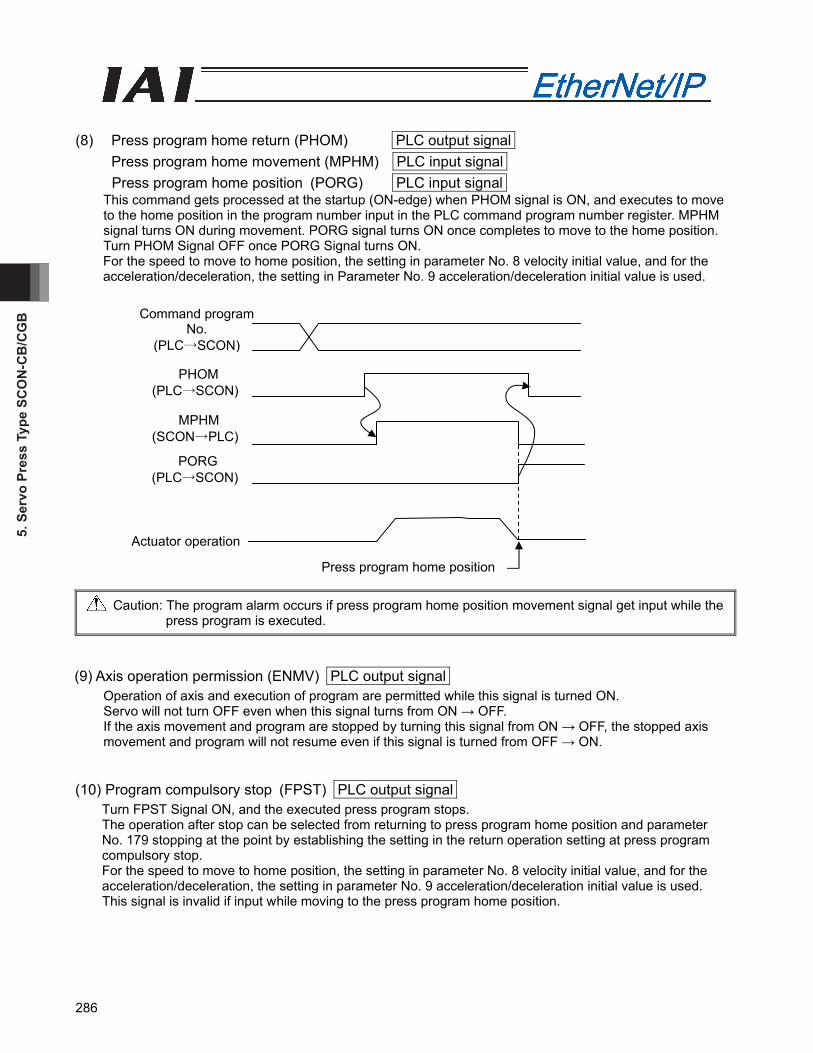
5. S
ervo
Pre
ss T
ype
SCO
N-C
B/C
GB
286
(8) Press program home return (PHOM) PLC output signal Press program home movement (MPHM) PLC input signal
Press program home position (PORG) PLC input signal This command gets processed at the startup (ON-edge) when PHOM signal is ON, and executes to move to the home position in the program number input in the PLC command program number register. MPHM signal turns ON during movement. PORG signal turns ON once completes to move to the home position. Turn PHOM Signal OFF once PORG Signal turns ON. For the speed to move to home position, the setting in parameter No. 8 velocity initial value, and for the acceleration/deceleration, the setting in Parameter No. 9 acceleration/deceleration initial value is used.
Press program home position
Caution: The program alarm occurs if press program home position movement signal get input while the press program is executed.
(9) Axis operation permission (ENMV) PLC output signal
Operation of axis and execution of program are permitted while this signal is turned ON. Servo will not turn OFF even when this signal turns from ON → OFF. If the axis movement and program are stopped by turning this signal from ON → OFF, the stopped axis movement and program will not resume even if this signal is turned from OFF → ON.
(10) Program compulsory stop (FPST) PLC output signal
Turn FPST Signal ON, and the executed press program stops. The operation after stop can be selected from returning to press program home position and parameter No. 179 stopping at the point by establishing the setting in the return operation setting at press program compulsory stop. For the speed to move to home position, the setting in parameter No. 8 velocity initial value, and for the acceleration/deceleration, the setting in parameter No. 9 acceleration/deceleration initial value is used.
This signal is invalid if input while moving to the press program home position.
Command program No.
(PLC→SCON)
PHOM (PLC→SCON)
MPHM (SCON→PLC)
PORG (PLC→SCON)
Actuator operation

5. Servo Press Type SCO
N-C
B/C
GB
287
(11) Probing stop (SSTP) PLC output signal When SSTP signal is ON at the time when probing stage completes, stops at probing stage complete position, and press program stop. Servo ON is continued. After program is turn off, even if SSTP signal return OFF will not resume press program.
(12) Jog/Inching switching (JISL) PLC output signal This signal changes over the jog operation and the inching operation. JISL=OFF : Jog operation JISL=ON : Inching operation When the JISL signal is turned “ON” (for inching operation) during the jog operation, the actuator is decelerated and performs the inching operation. When the JISL signal is turned OFF (jog) while the actuator is moving by inching, the actuator will complete the movement and then switch to the jog function. The table below summarizes the relationship of the ON/OFF statuses of the JISL signal and jog speed/inch-distance switching (JVEL) signal.
Jog operation Inching operation
JISL OFF ON Speed Parameter No. 26, “Jog speed” Parameter No. 26, “Jog speed” Travel - Parameter No. 48, “Inching distance”JVEL
=OFF Acceleration/ Deceleration
Rated value (The specific value varies depending on the actuator.)
Rated value (The specific value varies depending on the actuator.)
Speed Parameter No. 47, “Jog speed 2” Parameter No. 47, “Jog speed 2” Travel - Parameter No. 49 “Inching distance 2”JVEL
=ON Acceleration/ Deceleration
Rated value (The specific value varies depending on the actuator.)
Rated value (The specific value varies depending on the actuator.)
Operation When the JOG +/JOG – signal is ON.
Upon detection of the leading (ON) edge of the JOG +/JOG – signal.
(13) Jog-speed/Inching-distance switching (JVEL) PLC output signal
This change-over signal is used for the parameters specifying the jog speed when the jog operation is selected or the inching distance when the inching operation is selected. The relationship is as follows.
JVEL signal Jog operation: JISL=OFF Inching operation: JISL=ON
OFF Parameter No. 26, “Jog speed” Parameter No. 26, “Jog speed” Parameter No. 48, “Inching distance”
ON Parameter No. 47, “Jog speed 2” Parameter No. 47, “Jog speed 2” Parameter No. 49, “Inching distance 2”

5. S
ervo
Pre
ss T
ype
SCO
N-C
B/C
GB
288
(14) +Jog (JOG+) PLC output signal
-Jog (JOG-) PLC output signal This signal is the command for the jog operation startup or inching operation startup. If a + command is issued, the actuator will operate in the direction opposite home. When a – command is issued, the actuator will operate in the direction of home.
[1] Jog operation Jog operation can be performed when the jog/inching switching (JISL) signal is OFF. While the “JOG+” is turned “ON”, the movement direction is to the opposite of the home and when it is turned “OFF”, the actuator is decelerated and stopped. While the JOG – is ON, the actuator will operate in the direction of home and when it is turned OFF, it is decelerated to a stop. The operation is performed based on the set values of the following parameters.
• The speed is based on the parameter value specified using the Jog speed/Inching distance change-over (JVEL) signal. If the JVEL signal is OFF, the actuator operates according to parameter No. 26, “PIO jog speed”. If the JVEL signal is ON, the actuator operates according to parameter No. 47, “PIO jog speed 2”.
• The acceleration/deceleration conforms to the rate acceleration/deceleration (the specific value varies depending on the actuator).
• When both the JOG+ and JOG- signals are turned “ON”, the actuator is decelerated and stopped.
[2] Inching operation The inching operation is available while the IISI signal is turned “ON”. Once it is turned “ON”, the actuator is moved as much as the inching distance. When the JOG+ is turned “ON”, the movement is to the opposite of the home and when the JOG- is turned “ON”, the movement is to the home. The operation is performed based on the set values of the following parameters.
• The speed conforms to the value of the parameter specified by the JVEL signal. If the JVEL signal is OFF, the actuator operates according to parameter No. 26, “PIO jog speed”. If the JVEL signal is ON, the actuator operates according to parameter No. 47, “PIO jog speed 2”.
• The travel conforms to the value of the parameter specified by the JVEL signal. If the JVEL signal is OFF, the actuator operates according to parameter No. 48, “PIO inch distance”. If the JVEL signal is ON, the actuator operates according to parameter No. 49, “PIO inch distance 2”.
• The Acceleration/Deceleration is based on the rated acceleration/deceleration (depending on the actuator).
During the normal operation, even when the “+” Jog signal or “-“ Jog signal is turned “ON”, the normal operation is continued. (The Jog signal is ignored) In the pause condition, even when the “+” Jog signal or “-“ Jog signal is turned “ON”, the actuator is not moved.
(Note) Because the software stroke limit is disabled before the home return operation, the actuator might run against the mechanism end. Take the greatest care.
(15) Positioning command (DSTR) PLC output signal
This signal is processed at the startup (ON-edge) and the positioning to the target position input in the PLC's target position register is performed. When this signal is issued in the condition where the home return operation has not performed at all after the power injection (HEND signal OFF), an alarm is issued (Operation Cancellation Level). Turn “OFF” this signal after confirming that the Positioning Completion Signal (PEND) signal has been turned “OFF”.

5. Servo Press Type SCO
N-C
B/C
GB
289
(16) Positioning completion signal (PEND) PLC input signal
This signal is turned “ON” when the actuator is moved to the target position and reaches the positioning band and the pressing is completed.
When the servo-motor is turned ON from OFF condition, the positioning is performed with the position set as the target position. Accordingly, this signal is turned “ON” and after that, when the positioning operation is started with the home return (HOME) signal, positioning command (DSTR) signal, this signal is turned “OFF”.
(17) Zone 1 (ZONE1) PLC input signal
Zone 2 (ZONE2) PLC input signal These signals are turned ON when the current position of the actuator is within the set area and turned OFF when the current position is out of the set area. The zone is set using the user parameters. The Zone 1 signal is set using the parameter No. 1 “Zone Boundary 1 “+” side” and No. 2 “Zone Boundary 1 “-“ side”. The Zone 2 signal is set using the parameter No. 23 “Zone Boundary 2 “+” side” and No. 24 “Zone Boundary 2 “–“ side”. The Zone 1 signal and Zone 2 signal become effective when the home return operation is completed. After that, even during the servo OFF, it is effective.
Caution: When the servo-motor is turned OFF or stopped in an emergency while the actuator is stopped at the target position, the PEND signal is turned “OFF” temporarily. Then, when the servo-motor is turned “ON” and the actuator is within the positioning band, the PEND signal is turned “ON” again. When the positioning is completed with the DSTR signal turned “ON”, the PEND signal is not turned “ON”.
Speed
Travel
Positioning band
Time
Target position
Timing at which the position complete signal turns ON
Zone signal
Actuator operation Home
Zone setting -
+ direction
Zone setting +
5. S
ervo
Pre
ss T
ype
SCO
N-C
B/C
GB
290
(18) Program alarm (PALM) PLC input signal
This turns ON when a press program alarm is detected. The alarm turns OFF when the reset (RES) signal gets turned ON if it is an operation cancelation level alarm. (without removing the cause of alarm, the alarm will be generated again when press program is executed.)
(19) Light failure status (ALML) PLC input signal
It turns to 1 when a message level (light alarm available to continue) alarm is generated. This signal is not linked to ALM_LED on the controller front panel. [Detail of the alarm refer to SCON controller instruction manual for servo press]
(20) Alarm (ALM) PLC input signal
When any error is detected using the controller protection circuit (function), it is turned “ON”. ■ Function When any error is detected and the protection circuit (function) is activated, this signal is turned “ON”. When the cause of the alarm is eliminated and the reset (RES) signal is turned “ON”, the alarm is turned “OFF” in the case that it is the alarm with the operation cancellation level. (In the case of the alarm with the cold start level, re-injection of the power is required) When the alarm is detected, the status indicator LED on the front surface of the controller illuminates in red.
(21) Emergency stop (EMGS) PLC input signal
When the controller is stopped in an emergency, it is turned “ON”. ■ Function When the controller is stopped in an emergency (motor driving power is cut OFF), it is turned “ON”. When the emergency stop status is cleared, it is turned “OFF”.
(22) While in approaching operation (APRC) PLC input signal
It turns ON during the approaching stage in press program. (23) While in probing operation (SERC) PLC input signal
It turns ON during the probing stage in press program. (24) While in pressurizing operation (PRSS) PLC input signal
It turns ON during the pressurizing stage in press program. (25) While in pressurizing stop (PSTP) PLC input signal
It turns ON at the stop after pressurizing in the pressurizing stage in press program.
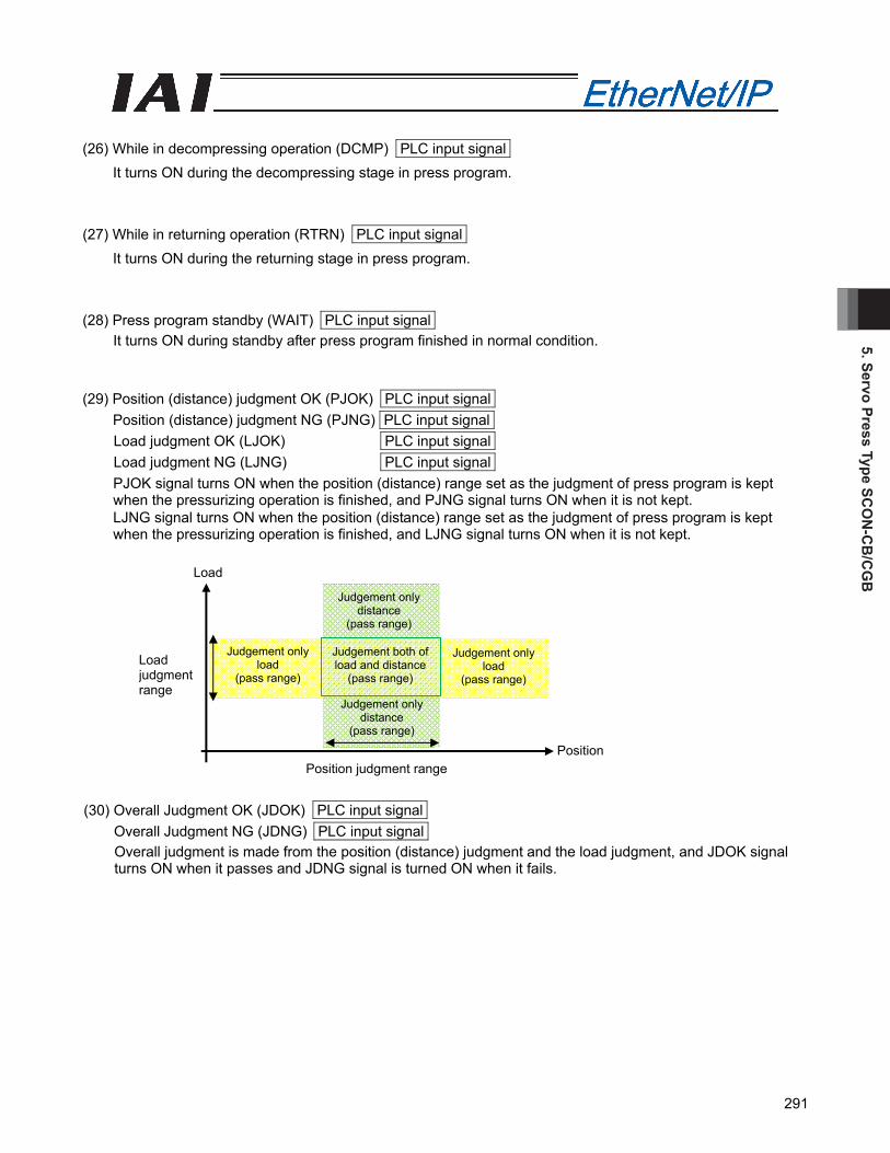
5. Servo Press Type SCO
N-C
B/C
GB
291
(26) While in decompressing operation (DCMP) PLC input signal
It turns ON during the decompressing stage in press program. (27) While in returning operation (RTRN) PLC input signal
It turns ON during the returning stage in press program. (28) Press program standby (WAIT) PLC input signal
It turns ON during standby after press program finished in normal condition. (29) Position (distance) judgment OK (PJOK) PLC input signal
Position (distance) judgment NG (PJNG) PLC input signal Load judgment OK (LJOK) PLC input signal Load judgment NG (LJNG) PLC input signal
PJOK signal turns ON when the position (distance) range set as the judgment of press program is kept when the pressurizing operation is finished, and PJNG signal turns ON when it is not kept. LJNG signal turns ON when the position (distance) range set as the judgment of press program is kept when the pressurizing operation is finished, and LJNG signal turns ON when it is not kept.
(30) Overall Judgment OK (JDOK) PLC input signal Overall Judgment NG (JDNG) PLC input signal
Overall judgment is made from the position (distance) judgment and the load judgment, and JDOK signal turns ON when it passes and JDNG signal is turned ON when it fails.
Load judgment range
Position judgment range
Load
Position
Judgement only load
(pass range)
Judgement onlydistance
(pass range)
Judgement onlyload
(pass range)
Judgement onlydistance
(pass range)
Judgement both of load and distance
(pass range)
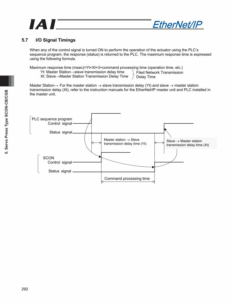
5. S
ervo
Pre
ss T
ype
SCO
N-C
B/C
GB
292
PLC sequence programControl signal
Status signal
SCON Control signal
Status signal
Master station → Slave transmission delay time (Yt)
Slave → Master station transmission delay time (Xt)
Command processing time
5.7 I/O Signal Timings
When any of the control signal is turned ON to perform the operation of the actuator using the PLC’s sequence program, the response (status) is returned to the PLC. The maximum response time is expressed using the following formula. Maximum response time (msec)=Yt+Xt+3+command processing time (operation time, etc.)
Yt: Master Station→slave transmission delay time Xt: Slave→Master Station Transmission Delay Time
Master Station→ For the master station → slave transmission delay (Yt) and slave → master station transmission delay (Xt), refer to the instruction manuals for the EtherNet/IP master unit and PLC installed in the master unit.
Filed Network Transmission Delay Time

5. Servo Press Type SCO
N-C
B/C
GB
293
5.8 Operation
The timings for the basic operation examples. (1) Operation in the remote I/O mode
Here, it shows examples for when executing one press program to turn the servo ON, return to home position and having loadcell calibration.
Example of operation
1) Turn ON (operation enable) axis movement permission signal (ENMV). 2) Indicate the press program number (PC1 to PC32). 3) Turn the press program home position movement signal (PHOM) ON. During the movement to home
position, the press program home position movement signal is kept ON. The press program home position signal (PORG) turns ON once the home position movement completes.
4) Turn the press program start signal (PSTR) on to execute the press program. The press program execution signal (PRUN) turns ON while the press program is executed *.
* Duration from program start till standby time pass after return stage 5) Each stage execution signal is kept on while each stage in the press program is executed.
While in approaching stage executed = While in approaching operation signal (APRC) While in probing stage executed = While in probing operation signal (SERC)
While in pressurizing stage (pressurize) executed = While in pressurizing operation (APRC) While in pressurizing stage (stop) executed = While in pressurizing stop (PSTP)
6) Judgment made for pressurizing stop (PSTP ON). The result is output in judgment OK signal (JDOK) and judgment NG signal (JDNG). 7) Once each of decompressing and return stage is finished, the press program normal complete signal
(PCMP) turns ON.
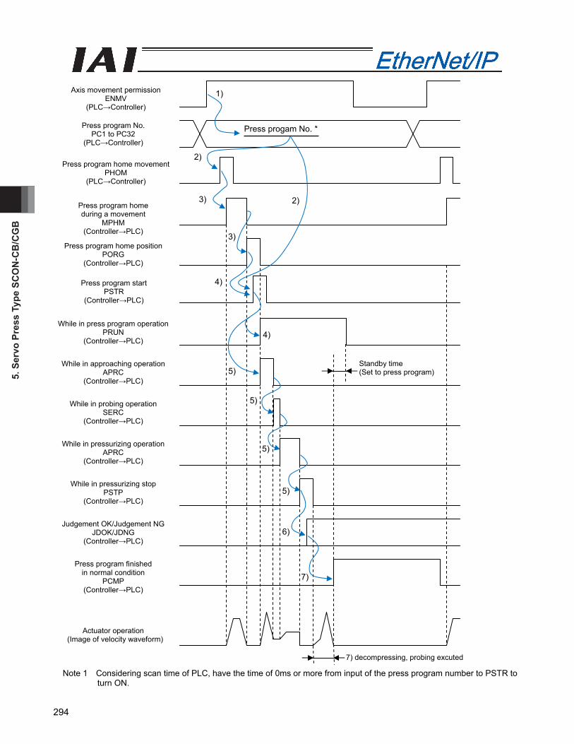
5. S
ervo
Pre
ss T
ype
SCO
N-C
B/C
GB
294
Note 1 Considering scan time of PLC, have the time of 0ms or more from input of the press program number to PSTR to
turn ON.
Press program No. PC1 to PC32
(PLC→Controller)
Press program start PSTR
(Controller→PLC)
Press program home movement PHOM
(PLC→Controller)
Press program home during a movement
MPHM (Controller→PLC)
Press progam No. *
Press program home position PORG
(Controller→PLC)
While in press program operation PRUN
(Controller→PLC)
While in approaching operation APRC
(Controller→PLC)
While in probing operation SERC
(Controller→PLC)
While in pressurizing operation APRC
(Controller→PLC)
While in pressurizing stop PSTP
(Controller→PLC)
Judgement OK/Judgement NG JDOK/JDNG
(Controller→PLC)
Press program finished in normal condition
PCMP (Controller→PLC)
Actuator operation (Image of velocity waveform)
7) decompressing, probing excuted
Standby time (Set to press program)
1)
2)
3) 2)
4)
3)
4)
6)
5)
5)
5)
5)
7)
Axis movement permission ENMV
(PLC→Controller)

5. Servo Press Type SCO
N-C
B/C
GB
295
(2) Operation in the full function mode
Here, it shows examples for [1] when executing one press program and [2] when performing direct indication movement to the target position after completing to turn the servo ON, return to home position and having loadcell calibration. [1] Example for when executing one press program
1) Turn ON (operation enable) axis movement permission signal (ENMV). 2) Set the press program number to execute to the command program number register. 3) Turn the press program home position movement signal (PHOM) ON. During the movement to home
position, the press program home position movement signal is kept ON. The press program home position signal (PORG) turns ON once the home position movement completes.
4) Turn the press program start signal (PSTR) ON to execute the press program. The press program execution signal (PRUN) turns ON while the press program is executed *. * Duration from program start till standby time pass after return stage
5) Each stage execution signal is kept ON while each stage in the press program is executed. While in approaching stage executed = While in approaching operation signal (APRC)
While in probing stage executed = While in probing operation signal (SERC) While in pressurizing stage (pressurize) executed = While in pressurizing operation (APRC)
While in pressurizing stage (stop) executed = While in pressurizing stop (PSTP) 6) Judgment made for pressurizing stop (PSTP ON). The position (distance) result is output in judgement OK signal (PJOK), judgment NG signal (PJNG).
The load result is output in judgment OK signal (LJOK), judgment NG signal (LJNG). The overall judgement result is output in judgment OK signal (JDOK), judgment NG signal (JDNG).
7) Executing signal for each stage turns ON during operation of each stage in press program. While decompressing stage executed = While decompressing operation signal (DCMP)
While returning stage executed = While returning operation signal (RTRN) 8) Once each of decompressing and return stage is finished, the press program normal complete signal
(PCMP) turns ON, stops operation for the duration of standby time set in the press program, and turns ON the press program standby signal (WAIT). Wait for the standby time before making a command when the next press program is to be executed.
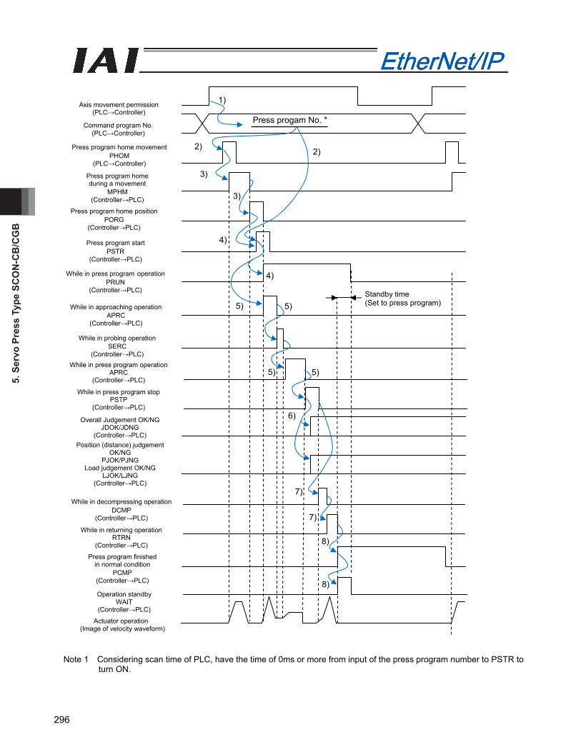
5. S
ervo
Pre
ss T
ype
SCO
N-C
B/C
GB
296
Note 1 Considering scan time of PLC, have the time of 0ms or more from input of the press program number to PSTR to
turn ON.
Press program home during a movement
MPHM (Controller→PLC)
Press progam No. *
Press program home position PORG
(Controller→PLC)
While in press program operation PRUN
(Controller→PLC)
While in approaching operation APRC
(Controller→PLC)
While in probing operation SERC
(Controller→PLC) While in press program operation
APRC (Controller→PLC)
While in press program stop PSTP
(Controller→PLC)
Overall Judgement OK/NG JDOK/JDNG
(Controller→PLC)
Press program finished in normal condition
PCMP (Controller→PLC)
Actuator operation (Image of velocity waveform)
Standby time (Set to press program)
1)
2)
3)
2)
4)
3)
4)
6)
5)
5) 5)
5)
7)
Axis movement permission (PLC→Controller)
Position (distance) judgement OK/NG
PJOK/PJNG Load judgement OK/NG
LJOK/LJNG (Controller→PLC)
While in decompressing operation
DCMP (Controller→PLC)
While in returning operation RTRN
(Controller→PLC)
Operation standby WAIT
(Controller→PLC)
8)
7)
8)
Press program start PSTR
(Controller→PLC)
Command program No. (PLC→Controller)
Press program home movement PHOM
(PLC→Controller)

5. Servo Press Type SCO
N-C
B/C
GB
297
[2] Example for when performing direct indication movement to the target position
1) Turn ON (operation enable) axis movement permission signal (ENMV). 2) Set the target position data in the target position register. 3) Set the positioning band data in the positioning band register. 4) Set the speed data to the speed resister. 5) Set the acceleration/deceleration data in the acceleration/deceleration register,. 6) In the condition where the positioning completion (PEND) signal is turned “ON”, turn “ON” the positioning
command (DSTR) signal. The data items set in Steps 2) through 5) are read in the controller at the startup (ON-edge) of the DSTR signal.
7) After the DSTR signal is turned “ON”, the PEND signal is turned “OFF” after tpdf. 8) After confirming that the PEND signal is turned “OFF”, turn “OFF” the DSTR signal. Do not change any
value in each register until the DSTR signal has been turned “OFF”. 9) When the DSTR signal is turned “OFF” and the motor current reaches the current-limiting value set in
Step 3), the PEND signal is turned “ON” .
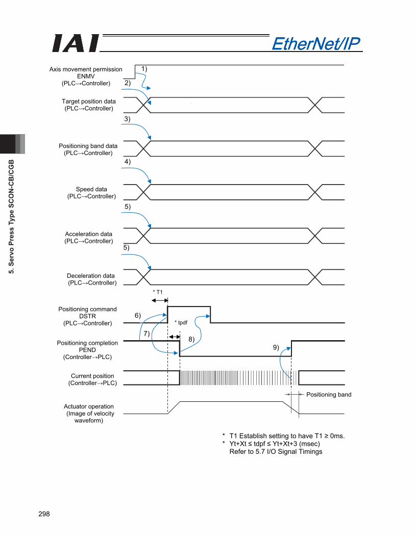
5. S
ervo
Pre
ss T
ype
SCO
N-C
B/C
GB
298
Target position data (PLC→Controller)
Acceleration data (PLC→Controller)
Positioning band data (PLC→Controller)
Speed data (PLC→Controller)
Positioning completion PEND
(Controller→PLC)
Deceleration data (PLC→Controller)
Positioning command DSTR
(PLC→Controller)
Current position (Controller→PLC)
Actuator operation (Image of velocity
waveform)
Axis movement permission ENMV
(PLC→Controller)
* T1
* tpdf
1)
2)
3)
4)
5)
6)
5)
7) 8)
9)
Positioning band
* T1 Establish setting to have T1 ≥ 0ms. * Yt+Xt ≤ tdpf ≤ Yt+Xt+3 (msec)
Refer to 5.7 I/O Signal Timings
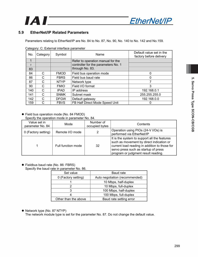
5. Servo Press Type SCO
N-C
B/C
GB
299
5.9 EtherNet/IP Related Parameters
Parameters relating to EtherNet/IP are No. 84 to No. 87, No. 90, No. 140 to No. 142 and No.159. Category: C: External interface parameter
No. Category Symbol Name Default value set in the factory before delivery
1
~ 83
Refer to operation manual for the controller for the parameters No. 1 through No. 83.
84 C FMOD Field bus operation mode 0 86 C FBRS Field bus baud rate 0 87 C NTYP Network type 7 90 C FMIO Field I/O format 3 140 C IPAD IP address 192.168.0.1 141 C SNMK Subnet mask 255.255.255.0 142 C DFGW Default gateway 192.168.0.0 159 C FBVS FB Half Direct Mode Speed Unit 0
Field bus operation mode (No. 84 FMOD) Specify the operation mode in parameter No. 84.
Value set in parameter No. 84 Mode Number of
occupied bytes Contents
0 (Factory setting) Remote I/O mode 2 Operation using PIOs (24-V I/Os) is performed via EtherNet/IP
1 Full function mode 32
It is the system to support all the features such as movement by direct indication or current load reading in addition to those for servo press such as startup of press program or judgment result reading.
Fieldbus baud rate (No. 86: FBRS) Specify the baud rate in parameter No. 86.
Set value Baud rate 0 (Factory setting) Auto negotiation (recommended)
1 10 Mbps, half-duplex 2 10 Mbps, full-duplex 3 100 Mbps, half-duplex 4 100 Mbps, full-duplex
Other than the above Baud rate setting error
Network type (No. 87 NTYP) The network module type is set for the parameter No. 87. Do not change the default value.
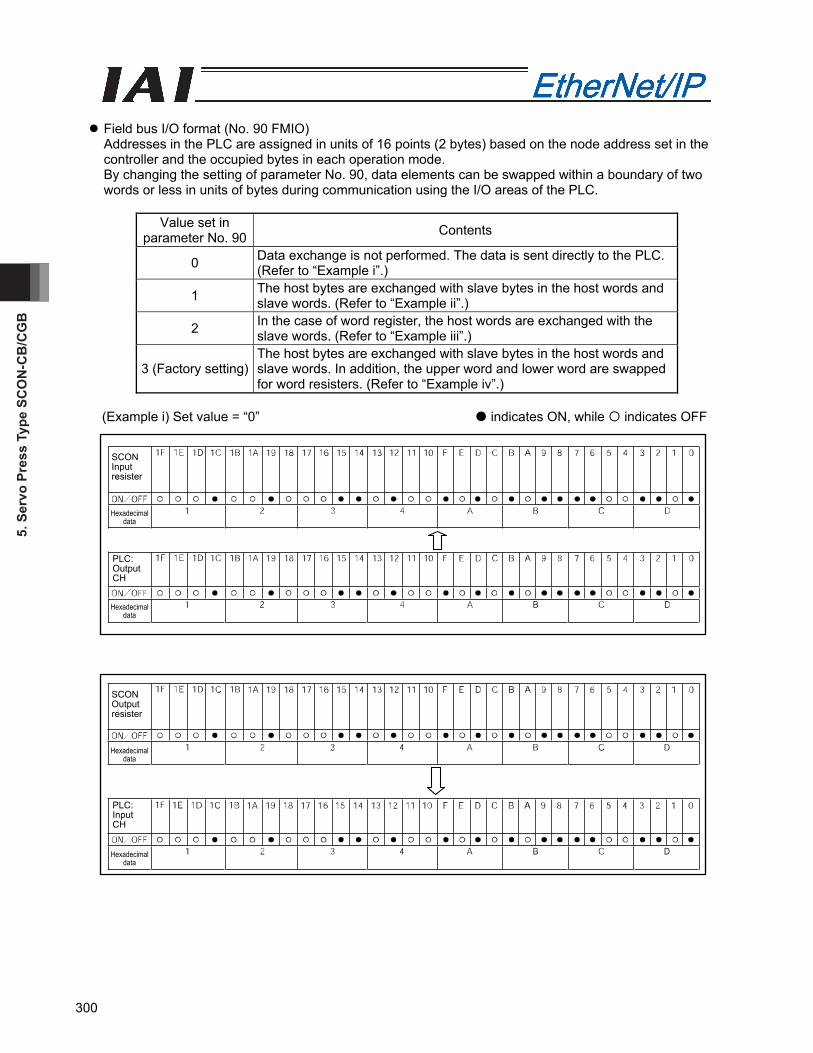
5. S
ervo
Pre
ss T
ype
SCO
N-C
B/C
GB
300
Field bus I/O format (No. 90 FMIO) Addresses in the PLC are assigned in units of 16 points (2 bytes) based on the node address set in the controller and the occupied bytes in each operation mode. By changing the setting of parameter No. 90, data elements can be swapped within a boundary of two words or less in units of bytes during communication using the I/O areas of the PLC.
Value set in
parameter No. 90 Contents
0 Data exchange is not performed. The data is sent directly to the PLC. (Refer to “Example i”.)
1 The host bytes are exchanged with slave bytes in the host words and slave words. (Refer to “Example ii”.)
2 In the case of word register, the host words are exchanged with the slave words. (Refer to “Example iii”.)
3 (Factory setting) The host bytes are exchanged with slave bytes in the host words and slave words. In addition, the upper word and lower word are swapped for word resisters. (Refer to “Example iv”.)
(Example i) Set value = “0” indicates ON, while indicates OFF
SCON Input resister
Hexadecimal data
PLC: Output CH
Hexadecimal data
SCON Output resister
Hexadecimal data
PLC: Input CH
Hexadecimal data
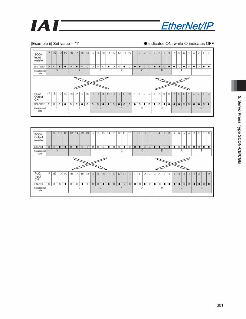
5. Servo Press Type SCO
N-C
B/C
GB
301
(Example ii) Set value = “1” indicates ON, while indicates OFF
SCON Input resister
SCON Output resister
Hexadecimal data
PLC: Output CH
PLC: Input CH
Hexadecimal data
Hexadecimal data
Hexadecimal data
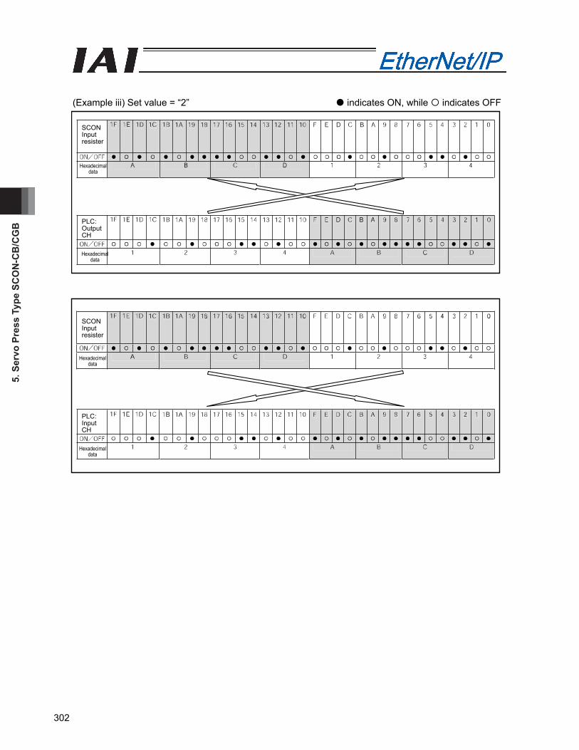
5. S
ervo
Pre
ss T
ype
SCO
N-C
B/C
GB
302
(Example iii) Set value = “2” indicates ON, while indicates OFF
SCON Input resister
SCON Input resister
Hexadecimal data
PLC: Output CH
PLC: Input CH
Hexadecimal data
Hexadecimal data
Hexadecimal data
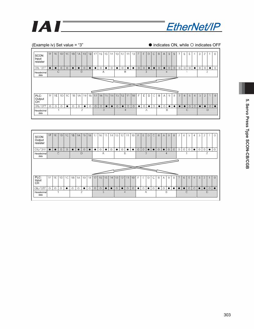
5. Servo Press Type SCO
N-C
B/C
GB
303
(Example iv) Set value = “3” indicates ON, while indicates OFF
SCON Input resister
SCON Output resister
Hexadecimal data
PLC: Output CH
PLC: Input CH
Hexadecimal data
Hexadecimal data
Hexadecimal data
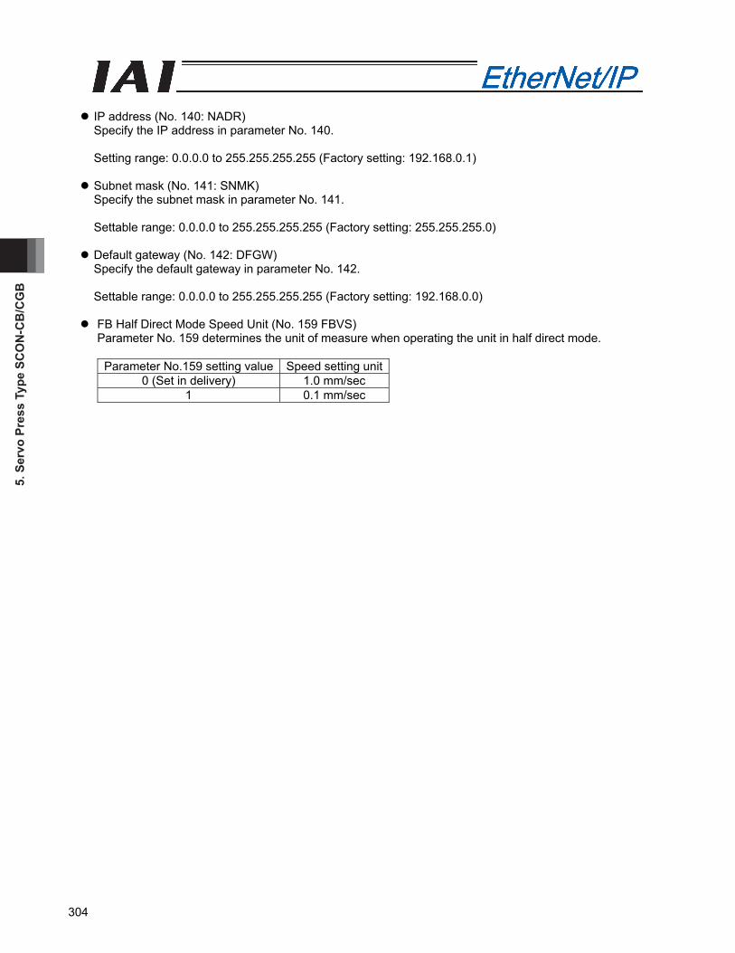
5. S
ervo
Pre
ss T
ype
SCO
N-C
B/C
GB
304
IP address (No. 140: NADR) Specify the IP address in parameter No. 140. Setting range: 0.0.0.0 to 255.255.255.255 (Factory setting: 192.168.0.1)
Subnet mask (No. 141: SNMK) Specify the subnet mask in parameter No. 141. Settable range: 0.0.0.0 to 255.255.255.255 (Factory setting: 255.255.255.0)
Default gateway (No. 142: DFGW) Specify the default gateway in parameter No. 142. Settable range: 0.0.0.0 to 255.255.255.255 (Factory setting: 192.168.0.0)
FB Half Direct Mode Speed Unit (No. 159 FBVS) Parameter No. 159 determines the unit of measure when operating the unit in half direct mode.
Parameter No.159 setting value Speed setting unit0 (Set in delivery) 1.0 mm/sec
1 0.1 mm/sec
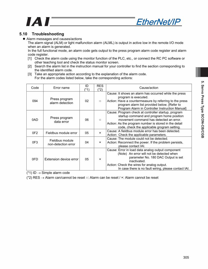
5. Servo Press Type SCO
N-C
B/C
GB
305
5.10 Troubleshooting
Alarm messages and causes/actions The alarm signal (ALM) or light malfunction alarm (ALML) is output in active low in the remote I/O mode when an alarm is generated. In the full functional mode, an alarm code gets output to the press program alarm code register and alarm code register. [1] Check the alarm code using the monitor function of the PLC, etc., or connect the RC PC software or
other teaching tool and check the status monitor screen. [2] Search the alarm list in the instruction manual for your controller to find the section corresponding to
the identified alarm code. [3] Take an appropriate action according to the explanation of the alarm code.
For the alarm codes listed below, take the corresponding actions:
Code Error name ID (*1)
RES(*2) Cause/action
094 Press program alarm detection 02 ○
Cause: It shows an alarm has occurred while the press program is executed.
Action: Have a countermeasure by referring to the press program alarm list provided below. [Refer to Program Alarm in Controller Instruction Manual]
0AD Press program data error 06 ○
Cause: Program check at controller startup, program startup command and program home position movement command has detected an error.
Action: As the program number is stored in the detail code, check the applicable grogram setting.
0F2 Fieldbus module error 05 × Cause: A fieldbus module error has been detected. Action: Check the applicable parameters.
0F3 Fieldbus module non-detection error 04 ×
Cause: The module could not be detected. Action: Reconnect the power. If the problem persists,
please contact IAI.
0FD Extension device error 05 ×
Cause: Error in load data analog output component (Note) An error will not be detected when
parameter No. 180 DAC Output is set inactivated.
Action: Check the wires for analog output. In case there is no fault wiring, please contact IAI.
(*1) ID → Simple alarm code (*2) RES → Alarm can/cannot be reset ○: Alarm can be reset / ×: Alarm cannot be reset
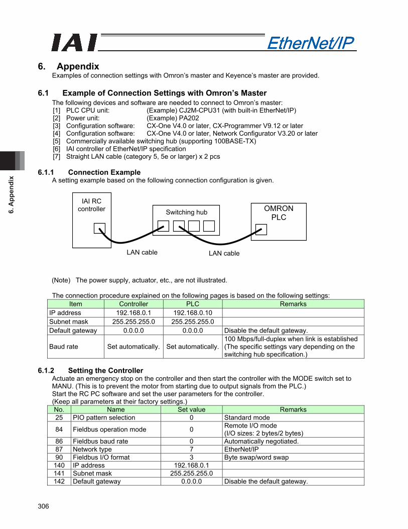
6. A
ppen
dix
306
OMRONPLC
IAI RC controller Switching hub
LAN cable LAN cable
6. Appendix
Examples of connection settings with Omron’s master and Keyence’s master are provided. 6.1 Example of Connection Settings with Omron’s Master
The following devices and software are needed to connect to Omron’s master: [1] PLC CPU unit: (Example) CJ2M-CPU31 (with built-in EtherNet/IP) [2] Power unit: (Example) PA202 [3] Configuration software: CX-One V4.0 or later, CX-Programmer V9.12 or later [4] Configuration software: CX-One V4.0 or later, Network Configurator V3.20 or later [5] Commercially available switching hub (supporting 100BASE-TX) [6] IAI controller of EtherNet/IP specification [7] Straight LAN cable (category 5, 5e or larger) x 2 pcs
6.1.1 Connection Example
A setting example based on the following connection configuration is given.
(Note) The power supply, actuator, etc., are not illustrated.
The connection procedure explained on the following pages is based on the following settings: Item Controller PLC Remarks
IP address 192.168.0.1 192.168.0.10 Subnet mask 255.255.255.0 255.255.255.0 Default gateway 0.0.0.0 0.0.0.0 Disable the default gateway.
Baud rate Set automatically. Set automatically.100 Mbps/full-duplex when link is established (The specific settings vary depending on the switching hub specification.)
6.1.2 Setting the Controller
Actuate an emergency stop on the controller and then start the controller with the MODE switch set to MANU. (This is to prevent the motor from starting due to output signals from the PLC.) Start the RC PC software and set the user parameters for the controller. (Keep all parameters at their factory settings.) No. Name Set value Remarks 25 PIO pattern selection 0 Standard mode
84 Fieldbus operation mode 0 Remote I/O mode (I/O sizes: 2 bytes/2 bytes)
86 Fieldbus baud rate 0 Automatically negotiated. 87 Network type 7 EtherNet/IP 90 Fieldbus I/O format 3 Byte swap/word swap
140 IP address 192.168.0.1 141 Subnet mask 255.255.255.0 142 Default gateway 0.0.0.0 Disable the default gateway.

6. Appendix
307
6.1.3 Setting the PLC (1) [CX-Programmer] [1] Set “NODE No.” rotary switches “x161” and “x160” to “0” and “A,” respectively, on the front face of the
CJ2M-CPU31 unit, and start the PLC. [2] Start CX-Programmer and click the [Connect Directly] button on the toolbar to connect to the PLC. [3] When the following message appears, select the [Also transfer I/O table and high-function unit settings]
check box and click the [Yes] button. [4] Click the [Program Mode] button to switch the PLC to the program mode. [5] Double-click “I/O Table/Unit Settings” in the workspace.
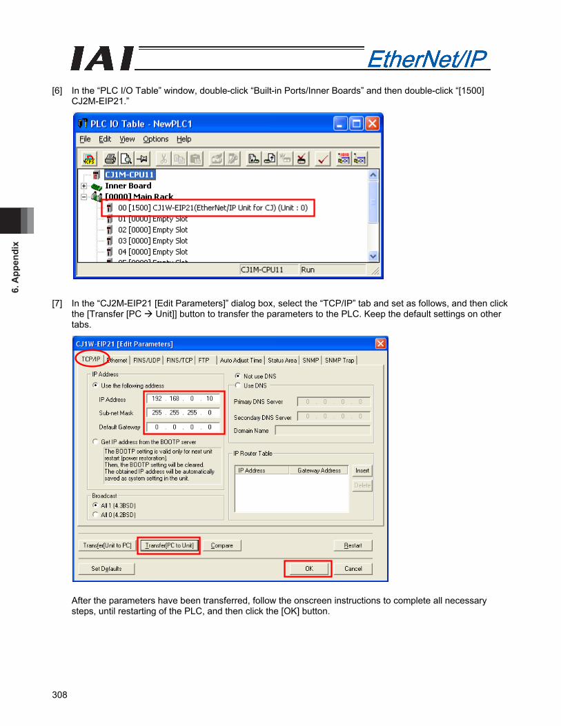
6. A
ppen
dix
308
[6] In the “PLC I/O Table” window, double-click “Built-in Ports/Inner Boards” and then double-click “[1500]
CJ2M-EIP21.” [7] In the “CJ2M-EIP21 [Edit Parameters]” dialog box, select the “TCP/IP” tab and set as follows, and then click
the [Transfer [PC Unit]] button to transfer the parameters to the PLC. Keep the default settings on other tabs.
After the parameters have been transferred, follow the onscreen instructions to complete all necessary steps, until restarting of the PLC, and then click the [OK] button.
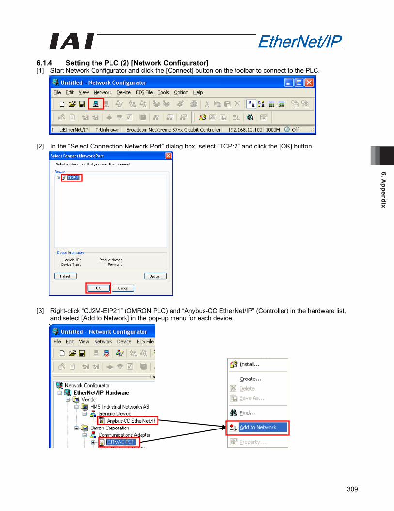
6. Appendix
309
6.1.4 Setting the PLC (2) [Network Configurator] [1] Start Network Configurator and click the [Connect] button on the toolbar to connect to the PLC. [2] In the “Select Connection Network Port” dialog box, select “TCP:2” and click the [OK] button. [3] Right-click “CJ2M-EIP21” (OMRON PLC) and “Anybus-CC EtherNet/IP” (Controller) in the hardware list,
and select [Add to Network] in the pop-up menu for each device.

6. A
ppen
dix
310
[4] Right-click each device in the main window and select [Change Node Address] in the pop-up menu to set
the IP address.
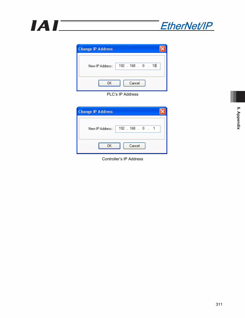
6. Appendix
311
PLC’s IP Address
Controller’s IP Address
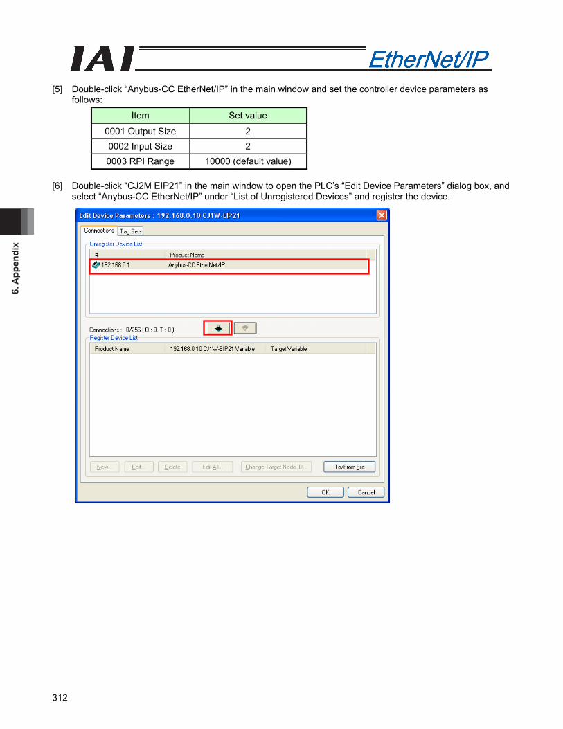
6. A
ppen
dix
312
[5] Double-click “Anybus-CC EtherNet/IP” in the main window and set the controller device parameters as
follows:
Item Set value
0001 Output Size 2 0002 Input Size 2 0003 RPI Range 10000 (default value)
[6] Double-click “CJ2M EIP21” in the main window to open the PLC’s “Edit Device Parameters” dialog box, and
select “Anybus-CC EtherNet/IP” under “List of Unregistered Devices” and register the device.
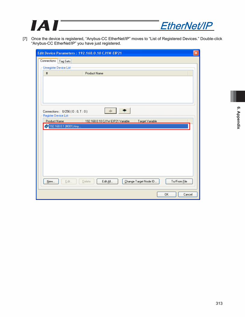
6. Appendix
313
[7] Once the device is registered, “Anybus-CC EtherNet/IP” moves to “List of Registered Devices.” Double-click
“Anybus-CC EtherNet/IP” you have just registered.
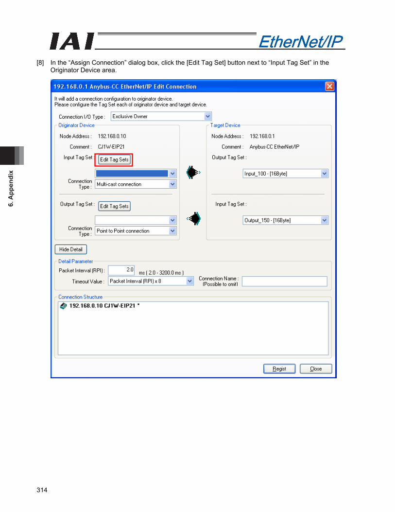
6. A
ppen
dix
314
[8] In the “Assign Connection” dialog box, click the [Edit Tag Set] button next to “Input Tag Set” in the
Originator Device area.
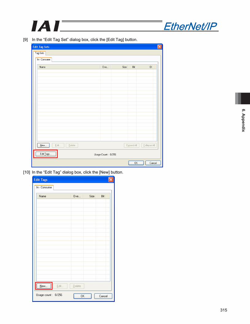
6. Appendix
315
[9] In the “Edit Tag Set” dialog box, click the [Edit Tag] button. [10] In the “Edit Tag” dialog box, click the [New] button.
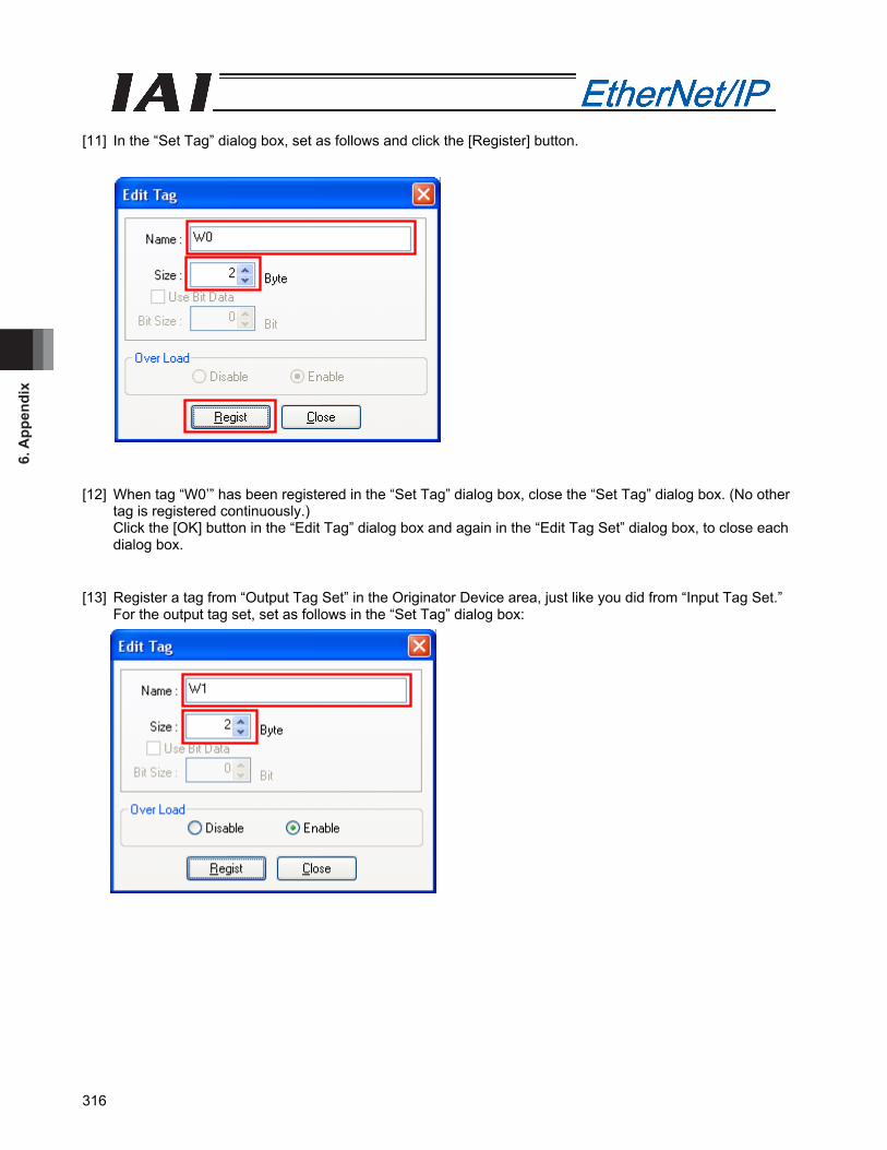
6. A
ppen
dix
316
[11] In the “Set Tag” dialog box, set as follows and click the [Register] button. [12] When tag “W0’” has been registered in the “Set Tag” dialog box, close the “Set Tag” dialog box. (No other
tag is registered continuously.) Click the [OK] button in the “Edit Tag” dialog box and again in the “Edit Tag Set” dialog box, to close each dialog box.
[13] Register a tag from “Output Tag Set” in the Originator Device area, just like you did from “Input Tag Set.”
For the output tag set, set as follows in the “Set Tag” dialog box:

6. Appendix
317
[14] In the “Assign Connection” dialog box, set as follows and click the [Register] button.
Confirm that the values in the “Target Device” area match those set in step [5]. [15] When the registration in “Assign Connection” is complete, the “Assign Connection” dialog box opens again.
Click the [Close] button to close the dialog box. [16] In the “Edit Device Parameters” dialog box, click the [OK] button.
Click the [Download to Network] button on the toolbar to start writing the parameters to the PLC, after which the PLC is restarted. Wait for several seconds, and link will be established between the PLC and controller.
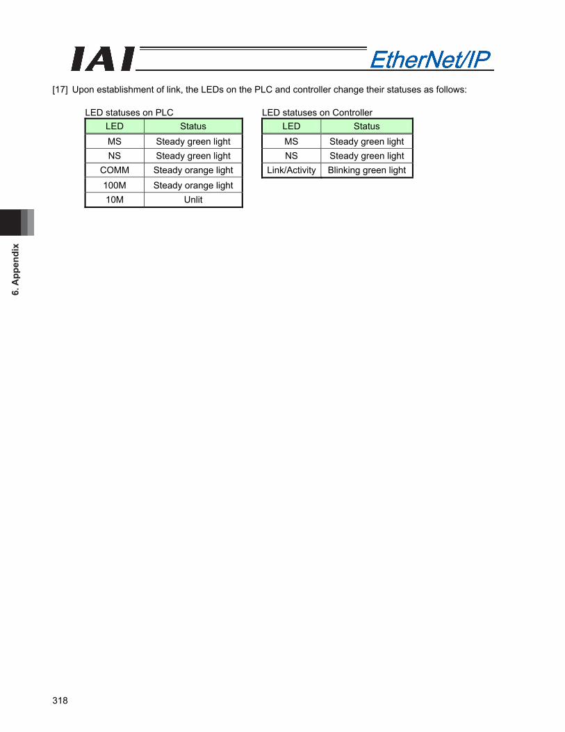
6. A
ppen
dix
318
[17] Upon establishment of link, the LEDs on the PLC and controller change their statuses as follows:
LED statuses on PLC LED statuses on Controller LED Status LED Status MS Steady green light MS Steady green light NS Steady green light NS Steady green light
COMM Steady orange light Link/Activity Blinking green light 100M Steady orange light 10M Unlit
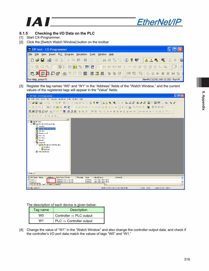
6. Appendix
319
6.1.5 Checking the I/O Data on the PLC [1] Start CX-Programmer. [2] Click the [Switch Watch Window] button on the toolbar. [3] Register the tag names “W0” and “W1” in the “Address” fields of the “Watch Window,” and the current
values of the registered tags will appear in the “Value” fields.
The description of each device is given below: Tag name Description
W0 Controller ⇒ PLC output W1 PLC ⇒ Controller output
[4] Change the value of “W1” in the “Watch Window” and also change the controller output data, and check if
the controller’s I/O port data match the values of tags “W0” and “W1.”
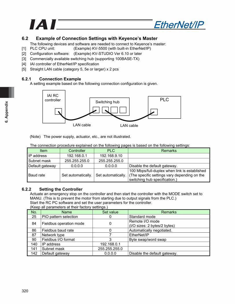
6. A
ppen
dix
320
PLCIAI RC
controller Switching hub
LAN cable LAN cable
6.2 Example of Connection Settings with Keyence’s Master
The following devices and software are needed to connect to Keyence’s master: [1] PLC CPU unit: (Example) KV-5500 (with built-in EtherNet/IP) [2] Configuration software: (Example) KV-STUDIO Ver 6.10 or later [3] Commercially available switching hub (supporting 100BASE-TX) [4] IAI controller of EtherNet/IP specification [5] Straight LAN cable (category 5, 5e or larger) x 2 pcs 6.2.1 Connection Example
A setting example based on the following connection configuration is given.
(Note) The power supply, actuator, etc., are not illustrated.
The connection procedure explained on the following pages is based on the following settings: Item Controller PLC Remarks
IP address 192.168.0.1 192.168.9.10 Subnet mask 255.255.255.0 255.255.255.0 Default gateway 0.0.0.0 0.0.0.0 Disable the default gateway.
Baud rate Set automatically. Set automatically.100 Mbps/full-duplex when link is established (The specific settings vary depending on the switching hub specification.)
6.2.2 Setting the Controller
Actuate an emergency stop on the controller and then start the controller with the MODE switch set to MANU. (This is to prevent the motor from starting due to output signals from the PLC.) Start the RC PC software and set the user parameters for the controller. (Keep all parameters at their factory settings.) No. Name Set value Remarks 25 PIO pattern selection 0 Standard mode
84 Fieldbus operation mode 0 Remote I/O mode (I/O sizes: 2 bytes/2 bytes)
86 Fieldbus baud rate 0 Automatically negotiated. 87 Network type 7 EtherNet/IP 90 Fieldbus I/O format 3 Byte swap/word swap
140 IP address 192.168.0.1 141 Subnet mask 255.255.255.0 142 Default gateway 0.0.0.0 Disable the default gateway.
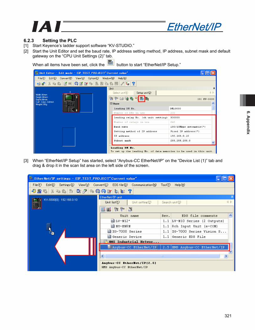
6. Appendix
321
6.2.3 Setting the PLC [1] Start Keyence’s ladder support software “KV-STUDIO.” [2] Start the Unit Editor and set the baud rate, IP address setting method, IP address, subnet mask and default
gateway on the “CPU Unit Settings (2)” tab.
When all items have been set, click the button to start “EtherNet/IP Setup.” [3] When “EtherNet/IP Setup” has started, select “Anybus-CC EtherNet/IP” on the “Device List (1)” tab and
drag & drop it in the scan list area on the left side of the screen.
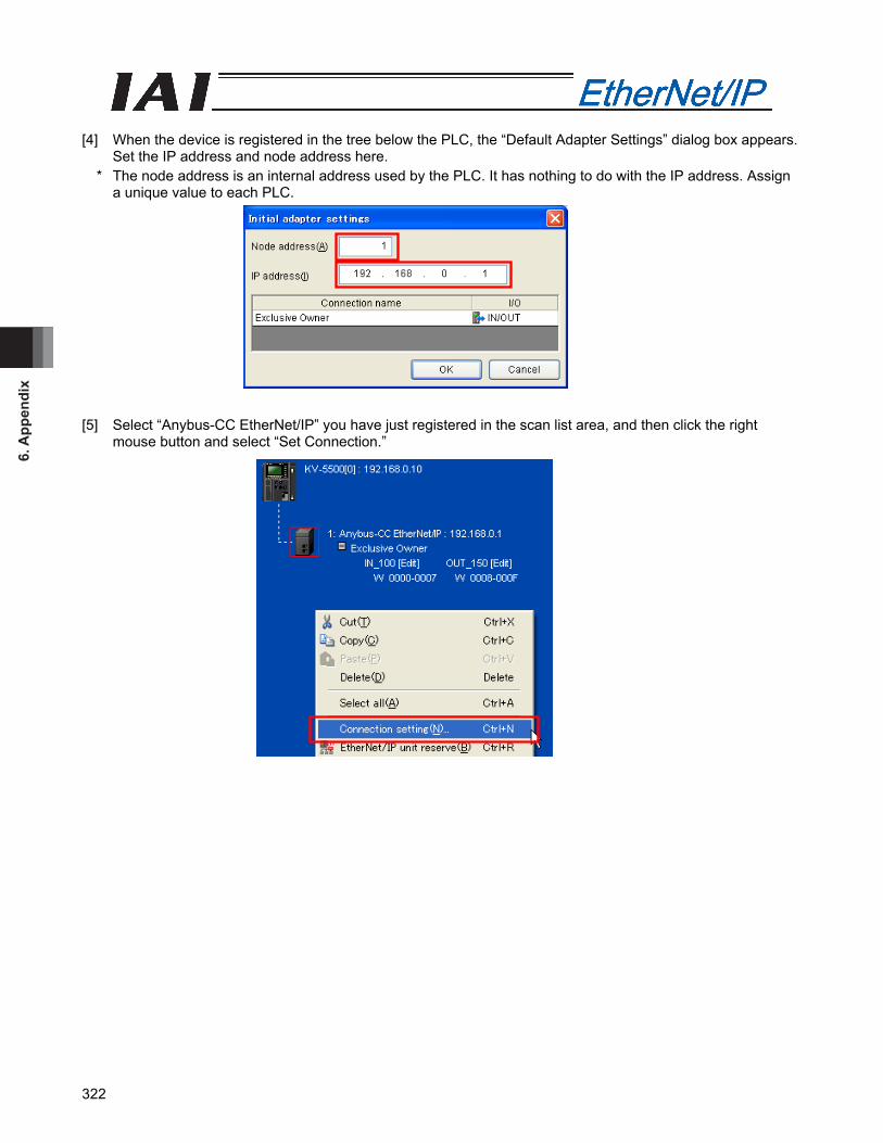
6. A
ppen
dix
322
[4] When the device is registered in the tree below the PLC, the “Default Adapter Settings” dialog box appears.
Set the IP address and node address here. * The node address is an internal address used by the PLC. It has nothing to do with the IP address. Assign
a unique value to each PLC. [5] Select “Anybus-CC EtherNet/IP” you have just registered in the scan list area, and then click the right
mouse button and select “Set Connection.”
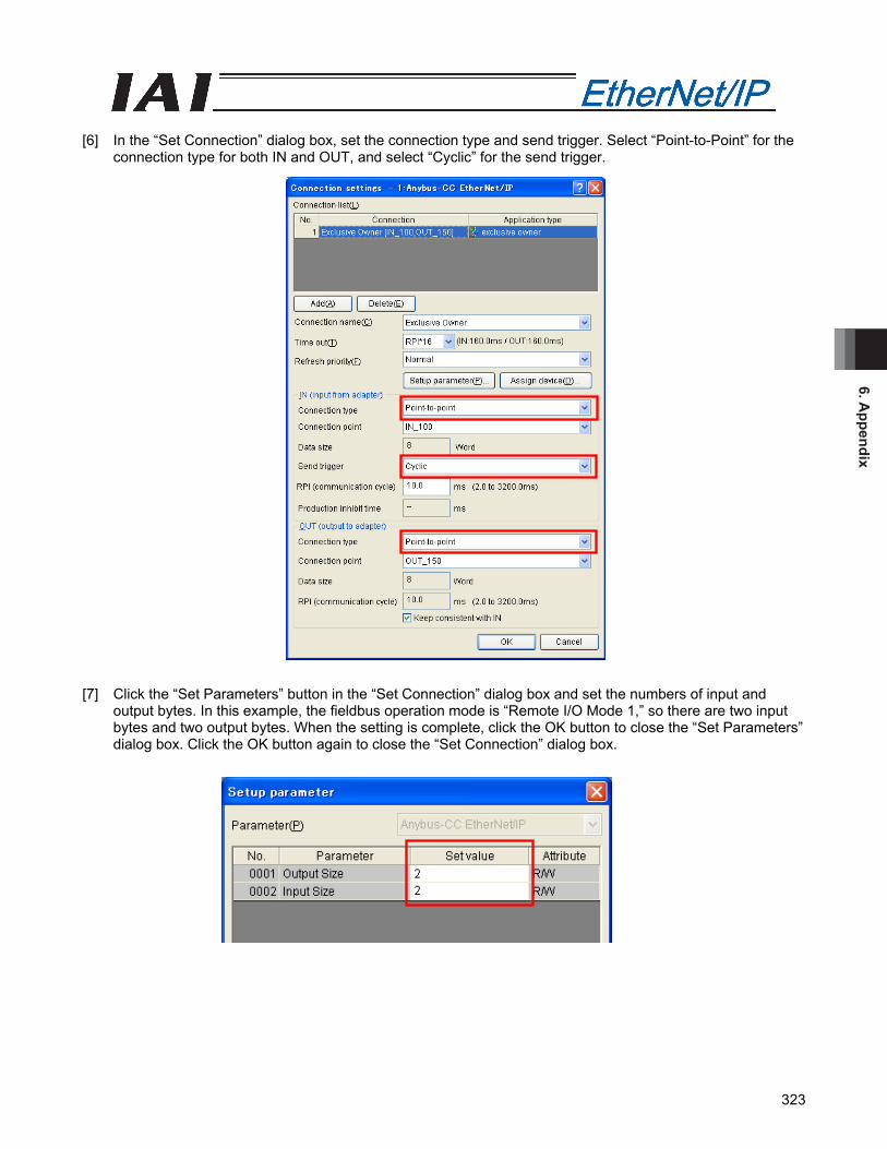
6. Appendix
323
[6] In the “Set Connection” dialog box, set the connection type and send trigger. Select “Point-to-Point” for the
connection type for both IN and OUT, and select “Cyclic” for the send trigger. [7] Click the “Set Parameters” button in the “Set Connection” dialog box and set the numbers of input and
output bytes. In this example, the fieldbus operation mode is “Remote I/O Mode 1,” so there are two input bytes and two output bytes. When the setting is complete, click the OK button to close the “Set Parameters” dialog box. Click the OK button again to close the “Set Connection” dialog box.
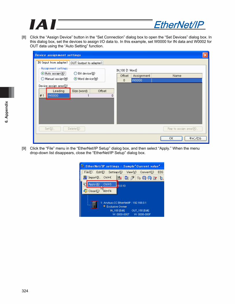
6. A
ppen
dix
324
[8] Click the “Assign Device” button in the “Set Connection” dialog box to open the “Set Devices” dialog box. In
this dialog box, set the devices to assign I/O data to. In this example, set W0000 for IN data and W0002 for OUT data using the “Auto Setting” function.
[9] Click the “File” menu in the “EtherNet/IP Setup” dialog box, and then select “Apply.” When the menu
drop-down list disappears, close the “EtherNet/IP Setup” dialog box.
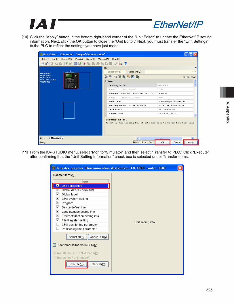
6. Appendix
325
[10] Click the “Apply” button in the bottom right-hand corner of the “Unit Editor” to update the EtherNet/IP setting
information. Next, click the OK button to close the “Unit Editor.” Next, you must transfer the “Unit Settings” to the PLC to reflect the settings you have just made.
[11] From the KV-STUDIO menu, select “Monitor/Simulator” and then select “Transfer to PLC.” Click “Execute”
after confirming that the “Unit Setting Information” check box is selected under Transfer Items.

6. A
ppen
dix
326
6.2.4 Checking the I/O Data on the PLC [1] Start KV-STUDIO in the “Monitor Mode.” [2] In the “Workspace” window, right-click “Anybus-CC EtherNet/IP” registered in the tree under KV-5500, and
select “Sensor I/O Monitor.” [3] After “Sensor I/O Monitor” has been selected, the “Sensor I/O Monitor” dialog box appears. In this dialog
box, you can monitor the devices to which I/O data has been assigned.
The description of each device is given below:
Tag name Description W00 PLC ← Controller W02 PLC → Controller
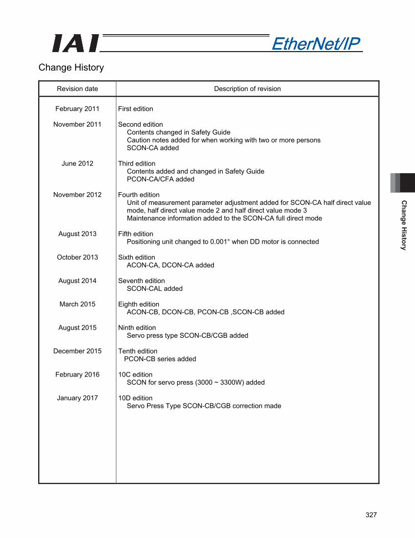
Change H
istory
327
Change History
Revision date Description of revision
February 2011
November 2011
June 2012
November 2012
August 2013
October 2013
August 2014
March 2015
August 2015
December 2015
February 2016
January 2017
First edition Second edition
Contents changed in Safety Guide Caution notes added for when working with two or more persons SCON-CA added
Third edition Contents added and changed in Safety Guide PCON-CA/CFA added
Fourth edition Unit of measurement parameter adjustment added for SCON-CA half direct value mode, half direct value mode 2 and half direct value mode 3 Maintenance information added to the SCON-CA full direct mode
Fifth edition Positioning unit changed to 0.001° when DD motor is connected
Sixth edition ACON-CA, DCON-CA added
Seventh edition
SCON-CAL added
Eighth edition ACON-CB, DCON-CB, PCON-CB ,SCON-CB added
Ninth edition Servo press type SCON-CB/CGB added
Tenth edition PCON-CB series added
10C edition SCON for servo press (3000 ~ 3300W) added
10D edition Servo Press Type SCON-CB/CGB correction made


Manual No.: ME0278-10D (January 2017)
The information contained in this document is subject to change without notice for purposes of product improvement.Copyright © 2017. Jan. IAI Corporation. All rights reserved.
17.01.000
Head Office: 577-1 Obane Shimizu-KU Shizuoka City Shizuoka 424-0103, JapanTEL +81-54-364-5105 FAX +81-54-364-2589
website: www.iai-robot.co.jp/
Ober der Röth 4, D-65824 Schwalbach am Taunus, GermanyTEL 06196-88950 FAX 06196-889524
SHANGHAI JIAHUA BUSINESS CENTER A8-303, 808, Hongqiao Rd. Shanghai 200030, ChinaTEL 021-6448-4753 FAX 021-6448-3992
website: www.iai-robot.com
825 PhairojKijja Tower 12th Floor, Bangna-Trad RD., Bangna, Bangna, Bangkok 10260, ThailandTEL +66-2-361-4458 FAX +66-2-361-4456
Technical Support available in USA, Europe and China
Head Office: 2690 W. 237th Street, Torrance, CA 90505TEL (310) 891-6015 FAX (310) 891-0815
Chicago Office: 110 East State Parkway, Schaumburg, IL 60173TEL (847) 908-1400 FAX (847) 908-1399
TEL (678) 354-9470 FAX (678) 354-9471website: www.intelligentactuator.com
Atlanta Office: 1220 Kennestone Circle, Suite 108, Marietta, GA 30066