expressive arduino controlled self-balancing robot
TRANSCRIPT
TVE 16 017 maj
Examensarbete 15 hp
Juni 2016
Expressive Arduino Controlled
Self-Balancing Robot
Johanna Blomstedt
Jonathan Haraldsson
Julia Nordin
I
Teknisk- naturvetenskaplig fakultet
UTH-enheten
Besöksadress: Ångströmlaboratoriet Lägerhyddsvägen 1 Hus 4, Plan 0 Postadress: Box 536 751 21 Uppsala Telefon: 018 – 471 30 03 Telefax: 018 – 471 30 00 Hemsida:
http://www.teknat.uu.se/student
Abstract
Expressive Arduino Controlled Self-Balancing
Robot
Johanna Blomstedt, Jonathan Haraldsson & Julia Nordin
Handledare: Jörgen Olsson, Uwe Zimmermann
Ämnesgranskare: Lisa Åkerlund
Examinator: Martin Sjödin
ISSN: 1401-5757, TVE 16 017 maj
A robot capable of balancing itself on two wheels has been built and programmed. While balancing, the robot keeps within a limited area. The robot has a face with two eyes and a mouth, consisting of LED-matrices, which switch between six different facial expressions. The robot is programmed using Arduino boards, one of which implements PID regulators to control the motors.
II
Populärvetenskaplig sammanfattning
Robotteknologi är en växande marknad då vårt samhälle blir alltmer automatiserat. Arduino är
ett företag som sedan 2005 tagit fram kretskort med inbyggda mikrokontrollers. Arduinos syfte
är att göra det möjligt för privata personer med begränsade kunskaper inom ämnet att
exempelvis bygga en robot. I detta projekt har en självbalanserande robot byggts och
programmerats så att den inom en begränsad golvyta kan balansera på två hjul. Den har ett
ansikte bestående av två ögon och en mun som utgörs av LED-skärmar och uttrycker sex olika
ansiktsuttryck. Roboten är konstruerad av material som finns lättillgängligt på marknaden för
privatpersoner.
Acknowledgements
We want to say thank you to those who helped us and made this project
possible.
Uwe Zimmermann – For all the help and supervision and for the 3D-printed hubs. For
having an equally wide range of electric components in the office as the entire Ebay, and for
providing us with new ones when we fried our own. You helped us continue our work right
away and gave us new hope when we got lost.
Jörgen Olsson – for the supervision and encouragement to us and our project, for showing
a genuine interest in our robot, for the UU-sticker and for welcoming and including us in the
department.
Svante Andersson – for letting us use the workshop and giving us advice and materials.
The department of solid-state electronics – for fredagsfika, for letting us occupy
the couches and for having the patience to listen to our music in the electric lab.
And to the companies supporting our project:
Conrad Electrokit
NOW Syntronic
LEAB Apem
Robotdalen
Table of Contents Acknowledgements ...................................................................................................................................................... II
Populärvetenskaplig sammanfattning........................................................................................................................ II
Introduction ................................................................................................................................................................... 1
Background ................................................................................................................................................................ 1
Purpose ....................................................................................................................................................................... 1
Theory ............................................................................................................................................................................. 1
Control Theory .......................................................................................................................................................... 1
PID-Regulators ......................................................................................................................................................... 3
FIR-filter ..................................................................................................................................................................... 3
Pulse Width Modulation .......................................................................................................................................... 4
Accelerometer............................................................................................................................................................ 4
Gyroscope .................................................................................................................................................................. 4
I2C................................................................................................................................................................................ 4
Libraries ...................................................................................................................................................................... 4
Material ............................................................................................................................................................................ 5
Arduino....................................................................................................................................................................... 5
Arduino Uno ............................................................................................................................................................. 5
Arduino Leonardo .................................................................................................................................................... 5
Arduino Motor Shield .............................................................................................................................................. 5
H-Bridge ..................................................................................................................................................................... 5
IMU ............................................................................................................................................................................. 6
Voltage Regulator LM7805 ..................................................................................................................................... 7
Encoders .................................................................................................................................................................... 7
NeoPixel-matrices ..................................................................................................................................................... 7
LEDmatrix and MAX7219 ..................................................................................................................................... 8
List of materials ......................................................................................................................................................... 8
Process ..........................................................................................................................................................................10
Construction ............................................................................................................................................................10
Shelves ..................................................................................................................................................................10
Engine Mount .....................................................................................................................................................10
Assembly ..................................................................................................................................................................10
Arduino Uno, Leonardo and Motor Shield ...................................................................................................10
Replacement motor controller .........................................................................................................................10
Motors ..................................................................................................................................................................11
Batteries ...............................................................................................................................................................11
Breadboards ........................................................................................................................................................11
IMU-sensor .........................................................................................................................................................11
LED-Matrices .....................................................................................................................................................11
Diode “antennas” ...............................................................................................................................................11
Pushbutton Switches .........................................................................................................................................11
Chassis ..................................................................................................................................................................11
Troubleshooting ......................................................................................................................................................12
Using an oscilloscope ........................................................................................................................................12
In the code ...........................................................................................................................................................12
Programming ...........................................................................................................................................................12
Test code..............................................................................................................................................................12
IMU-sensor .............................................................................................................................................................. 12
Motors....................................................................................................................................................................... 12
Arduino Leonardo ..............................................................................................................................................13
Leonardo.ino ............................................................................................................................................................ 13
Finding regulator parameters ................................................................................................................................ 13
Alternative way of finding regulator parameters ........................................................................................... 14
Motors.ino ................................................................................................................................................................ 14
Arduino Uno (encoder) .....................................................................................................................................14
Arduino Uno (face) ............................................................................................................................................14
Uno2.ino ................................................................................................................................................................... 14
RGB.h ....................................................................................................................................................................... 15
Mouth.h .................................................................................................................................................................... 15
Result .............................................................................................................................................................................16
Discussion.....................................................................................................................................................................20
Microcontrollers .................................................................................................................................................20
Common Mistakes .............................................................................................................................................20
Improvements .....................................................................................................................................................20
Steering ..................................................................................................................................................................... 20
Parameters ................................................................................................................................................................ 21
Face ........................................................................................................................................................................... 21
Chassis ...................................................................................................................................................................... 21
Filters ........................................................................................................................................................................ 21
Wires ......................................................................................................................................................................... 21
Conclusion ....................................................................................................................................................................22
References .....................................................................................................................................................................23
Appendix .......................................................................................................................................................................... i
Appendix I: ................................................................................................................................................................. i
Main code ............................................................................................................................................................... i
Leonardo.ino ............................................................................................................................................................... i
Motors.ino ............................................................................................................................................................... viii
Appendix II: ............................................................................................................................................................... x
Wheel encoders ..................................................................................................................................................... x
Uno1.ino ..................................................................................................................................................................... x
Appendix III: .......................................................................................................................................................... xiii
Face ...................................................................................................................................................................... xiii
Uno2.ino .................................................................................................................................................................. xiii
RGB.h .................................................................................................................................................................... xviii
Mouth.h ................................................................................................................................................................... xix
Appendix IV ........................................................................................................................................................... xxi
Test Codes .......................................................................................................................................................... xxi
Imu.ino .................................................................................................................................................................... xxi
I2C.ino ................................................................................................................................................................... xxvi
Display.ino .......................................................................................................................................................... xxviii
testMotors.ino ...................................................................................................................................................... xxix
Appendix V ............................................................................................................................................................xxx
Schematics .........................................................................................................................................................xxx
Appendix VI ........................................................................................................................................................ xxxi
Alternative way of getting PID-parameters ............................................................................................... xxxi
PID_parameters.m .............................................................................................................................................. xxxi
1
Introduction
Background The story of the commercial microcontroller starts a few decades before Arduino technology,
with the arrival of the 4-bit Intel 4004 in 1971. The Intel 4004 was the first commercial chip, and
the second complete singlechip CPU (Central Processing Unit) of all time. The following year the
8-bit Intel 8008 was released, which formed the basis of the first PCs (Personal Computers). In
1975 the Microchip Technology’s PIC (Programmable Interface Controller) microcontrollers
were invented. [1] This is the early beginning of Arduino.
In 2004 a development platform, Wiring, was created by Hernando Barragán. In 2005 the
founders of Arduino forked the Wiring sources, the same year the first Arduino was introduced
[2]. Arduino started as a project, which was mainly addressed to students as a way to access
embedded microprocessors more easily. [3]
There are many other boards similar to the Arduino board on the market. However, because of
Arduino’s IDE (Integrated Development Environment), they are the first choice of many
beginners. Arduino have managed to combine the IDE to a user-friendly environment that is
easy to use.
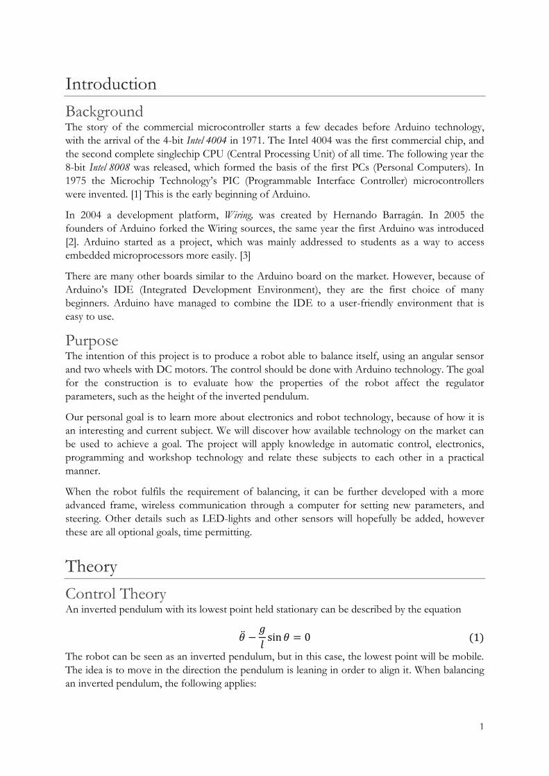
Purpose The intention of this project is to produce a robot able to balance itself, using an angular sensor
and two wheels with DC motors. The control should be done with Arduino technology. The goal
for the construction is to evaluate how the properties of the robot affect the regulator
parameters, such as the height of the inverted pendulum.
Our personal goal is to learn more about electronics and robot technology, because of how it is
an interesting and current subject. We will discover how available technology on the market can
be used to achieve a goal. The project will apply knowledge in automatic control, electronics,
programming and workshop technology and relate these subjects to each other in a practical
manner.
When the robot fulfils the requirement of balancing, it can be further developed with a more
advanced frame, wireless communication through a computer for setting new parameters, and
steering. Other details such as LED-lights and other sensors will hopefully be added, however
these are all optional goals, time permitting.
Theory
Control Theory An inverted pendulum with its lowest point held stationary can be described by the equation
−𝑔
𝑙sin 𝜃 = 0 (1)
The robot can be seen as an inverted pendulum, but in this case, the lowest point will be mobile.
The idea is to move in the direction the pendulum is leaning in order to align it. When balancing
an inverted pendulum, the following applies:
2
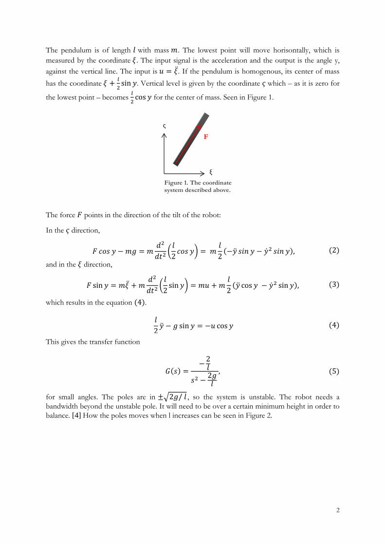
The pendulum is of length 𝑙 with mass 𝑚. The lowest point will move horisontally, which is
measured by the coordinate 𝜉. The input signal is the acceleration and the output is the angle y,
against the vertical line. The input is 𝑢 = . If the pendulum is homogenous, its center of mass
has the coordinate 𝜉 +𝑙
2sin 𝑦. Vertical level is given by the coordinate 𝜍 which – as it is zero for
the lowest point – becomes 𝑙
2cos 𝑦 for the center of mass. Seen in Figure 1.
The force 𝐹 points in the direction of the tilt of the robot:
In the 𝜍 direction,
𝐹 𝑐𝑜𝑠 𝑦 − 𝑚𝑔 = 𝑚𝑑2
𝑑𝑡2(
𝑙
2𝑐𝑜𝑠 𝑦) = 𝑚
𝑙
2(− 𝑠𝑖𝑛 𝑦 − 2 𝑠𝑖𝑛 𝑦), (2)
and in the 𝜉 direction,
𝐹 sin 𝑦 = 𝑚 + 𝑚𝑑2
𝑑𝑡2(
𝑙
2sin 𝑦) = 𝑚𝑢 + 𝑚
𝑙
2( cos 𝑦 − 2 sin 𝑦), (3)
which results in the equation (4).
𝑙
2 − 𝑔 sin 𝑦 = −𝑢 cos 𝑦 (4)
This gives the transfer function
𝐺(𝑠) =−
2𝑙
𝑠2 −2𝑔𝑙
, (5)
for small angles. The poles are in ±√2𝑔/ 𝑙 , so the system is unstable. The robot needs a
bandwidth beyond the unstable pole. It will need to be over a certain minimum height in order to
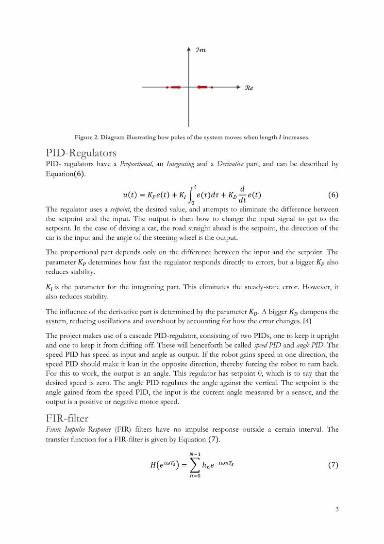
balance. [4] How the poles moves when l increases can be seen in Figure 2.
Figure 1. The coordinate system described above.
ξ
ς
F
3
ℐ𝓂
ℛℯ
Figure 2. Diagram illustrating how poles of the system moves when length 𝒍 increases.
PID-Regulators PID- regulators have a Proportional, an Integrating and a Derivative part, and can be described by
Equation(6).
𝑢(𝑡) = 𝐾𝑃𝑒(𝑡) + 𝐾𝐼 ∫ 𝑒(𝜏)𝑑𝜏𝑡
0
+ 𝐾𝐷
𝑑
𝑑𝑡𝑒(𝑡) (6)
The regulator uses a setpoint, the desired value, and attempts to eliminate the difference between
the setpoint and the input. The output is then how to change the input signal to get to the
setpoint. In the case of driving a car, the road straight ahead is the setpoint, the direction of the
car is the input and the angle of the steering wheel is the output.
The proportional part depends only on the difference between the input and the setpoint. The
parameter 𝐾𝑃 determines how fast the regulator responds directly to errors, but a bigger 𝐾𝑃 also
reduces stability.
𝐾𝐼 is the parameter for the integrating part. This eliminates the steady-state error. However, it
also reduces stability.
The influence of the derivative part is determined by the parameter 𝐾𝐷. A bigger 𝐾𝐷 dampens the
system, reducing oscillations and overshoot by accounting for how the error changes. [4]
The project makes use of a cascade PID-regulator, consisting of two PIDs, one to keep it upright
and one to keep it from drifting off. These will henceforth be called speed PID and angle PID. The
speed PID has speed as input and angle as output. If the robot gains speed in one direction, the
speed PID should make it lean in the opposite direction, thereby forcing the robot to turn back.
For this to work, the output is an angle. This regulator has setpoint 0, which is to say that the
desired speed is zero. The angle PID regulates the angle against the vertical. The setpoint is the
angle gained from the speed PID, the input is the current angle measured by a sensor, and the
output is a positive or negative motor speed.
FIR-filter Finite Impulse Response (FIR) filters have no impulse response outside a certain interval. The
transfer function for a FIR-filter is given by Equation (7).
𝐻(𝑒𝑖𝜔𝑇𝑠) = ∑ ℎ𝑛𝑒−𝑖𝜔𝑛𝑇𝑠
𝑁−1
𝑛=0
(7)
4
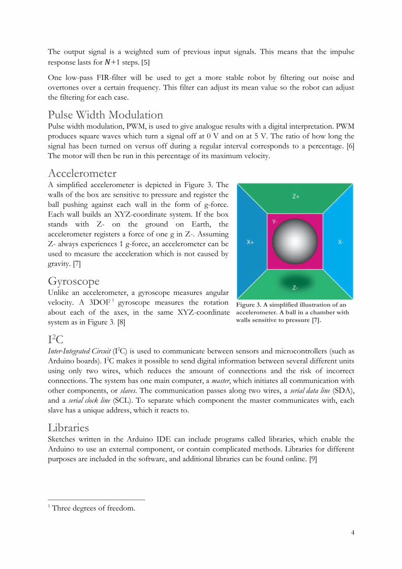
Figure 3. A simplified illustration of an accelerometer. A ball in a chamber with walls sensitive to pressure [7].
The output signal is a weighted sum of previous input signals. This means that the impulse
response lasts for 𝑁+1 steps. [5]
One low-pass FIR-filter will be used to get a more stable robot by filtering out noise and
overtones over a certain frequency. This filter can adjust its mean value so the robot can adjust
the filtering for each case.
Pulse Width Modulation Pulse width modulation, PWM, is used to give analogue results with a digital interpretation. PWM
produces square waves which turn a signal off at 0 V and on at 5 V. The ratio of how long the
signal has been turned on versus off during a regular interval corresponds to a percentage. [6]
The motor will then be run in this percentage of its maximum velocity.
Accelerometer A simplified accelerometer is depicted in Figure 3. The
walls of the box are sensitive to pressure and register the
ball pushing against each wall in the form of g-force.
Each wall builds an XYZ-coordinate system. If the box
stands with Z- on the ground on Earth, the
accelerometer registers a force of one g in Z-. Assuming
Z- always experiences 1 g-force, an accelerometer can be
used to measure the acceleration which is not caused by
gravity. [7]
Gyroscope Unlike an accelerometer, a gyroscope measures angular
velocity. A 3DOF 1 gyroscope measures the rotation
about each of the axes, in the same XYZ-coordinate
system as in Figure 3. [8]
I2C Inter-Integrated Circuit (I2C) is used to communicate between sensors and microcontrollers (such as
Arduino boards). I2C makes it possible to send digital information between several different units
using only two wires, which reduces the amount of connections and the risk of incorrect
connections. The system has one main computer, a master, which initiates all communication with
other components, or slaves. The communication passes along two wires, a serial data line (SDA),
and a serial clock line (SCL). To separate which component the master communicates with, each
slave has a unique address, which it reacts to.
Libraries Sketches written in the Arduino IDE can include programs called libraries, which enable the
Arduino to use an external component, or contain complicated methods. Libraries for different
purposes are included in the software, and additional libraries can be found online. [9]
1 Three degrees of freedom.
5
Material
Arduino A microcontroller is a computer small enough to be integrated into circuits. It has a processor,
program memory and working memory. Arduino hardware is a microcontroller on a chip.
The Arduino components used in the project have 20 in- and out-ports called pins. Of these,
some are digital and some analogue, and some pins have specific functions, such as PWM.
Arduino software is used to program the hardware. The programming language is C. [10] The
code is written in the IDE and each code is called a sketch. This is then uploaded from the
computer to the Arduino.
Arduino Uno Arduino Uno is based on the microcontroller ATmega328P. It features 32 kB Flash memory, 0.5
kB of which is used by the bootloader, and 2 kB SRAM-memory. It should be supplied with 7-12
V, but can handle voltages between 6-20 V. [10]
Arduino Leonardo The program also uses an Arduino Leonardo, which is an Arduino based on the microcontroller
ATmega32u4. This is the main computer of the circuit. It has 32 kB Flash memory, of which the
bootloader uses 4 kB, and 2.5 kB SRAM-memory. The Arduino Leonardo has the same
constraints on supply voltage as the Uno. [11]
Arduino Motor Shield Arduino Motor Shield is typically used to control motors, and can be used to drive two DC-
motors or one step-motor. Motor Shield is based on a L298 dual H-bridge driver, which gives the
motor the correct supply voltage in the correct polarity to get the desired velocity and direction.
The Motor Shield has the same configuration of pins as the Uno and Leonardo. This makes it
possible to mount the Motor Shield on one of these and use directly as the connection between
the processor and the motors. Ideal voltage to the Motor Shield is 7-12 V with limits between 5-
18 V. [12]
H-Bridge Another way to build a motor controller is to use two components, the L298 (seen in Figure 5)
and logic inverters. The L298 is an integrated circuit containing two H-bridges. An H-bridge is
basically the circuit in Figure 4 below, and one H-bridge controls one motor. There's a supply
voltage, in this case 12 V, a GND level and between these, the motor. When the switches are
open, no current passes through. When the switches on opposite sides and levels are closed, the
motors are supplied with 12 V. Which one of the opposite pairs is closed determines which
direction the motor will turn. [13]
The SN74HC04N has NOT logic gates, or inverters. These are used in the circuit to enable
direction control.

6
Figure 5. Pin configuration for L298. [21]
Figure 6. Back view of motor controller.
These two components make for a compact circuit. See Figure 5 for pin configuration. Pin 1, 8
and 15 are connected to each other and to the common GND node. Pin 2 and 3 are V+ and V-
for motor A (right motor). Pin 4 should be supplied with 12 V. Pin 5 inputs direction control for
motor A. Pin 7 is also connected to this line, but trough one of the inverters. PWM for motor A
goes to pin 6. Pin 9 should be supplied with 5 V. Pin 10 and 12 are direct and inverted direction
control for motor B (left motor). PWM for motor B connects to pin 11. Pin 13 and 14 are V+
and V- for motor B. The circuit fits on a small breadboard, see Figure 7 and Figure 6.
IMU A 6DOF 2 IMU-sensor 3 is mounted on the robot. The IMU-sensor is equipped with an
accelerometer and a gyroscope, which each have three axes. [14] By using both an accelerometer
and a gyroscope, a more exact reading can be made, with six degrees of freedom.
2 Six degrees of freedom. 3 Inertial Measurement Unit.
Figure 7. Front view of motor controller.
Figure 4. H-bridge with different switches closed. [20]
7
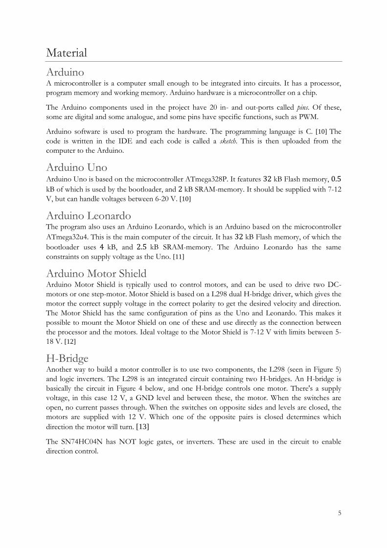
Figure 9. Poles of the encoder, forms footprints in a thin magnetic film.
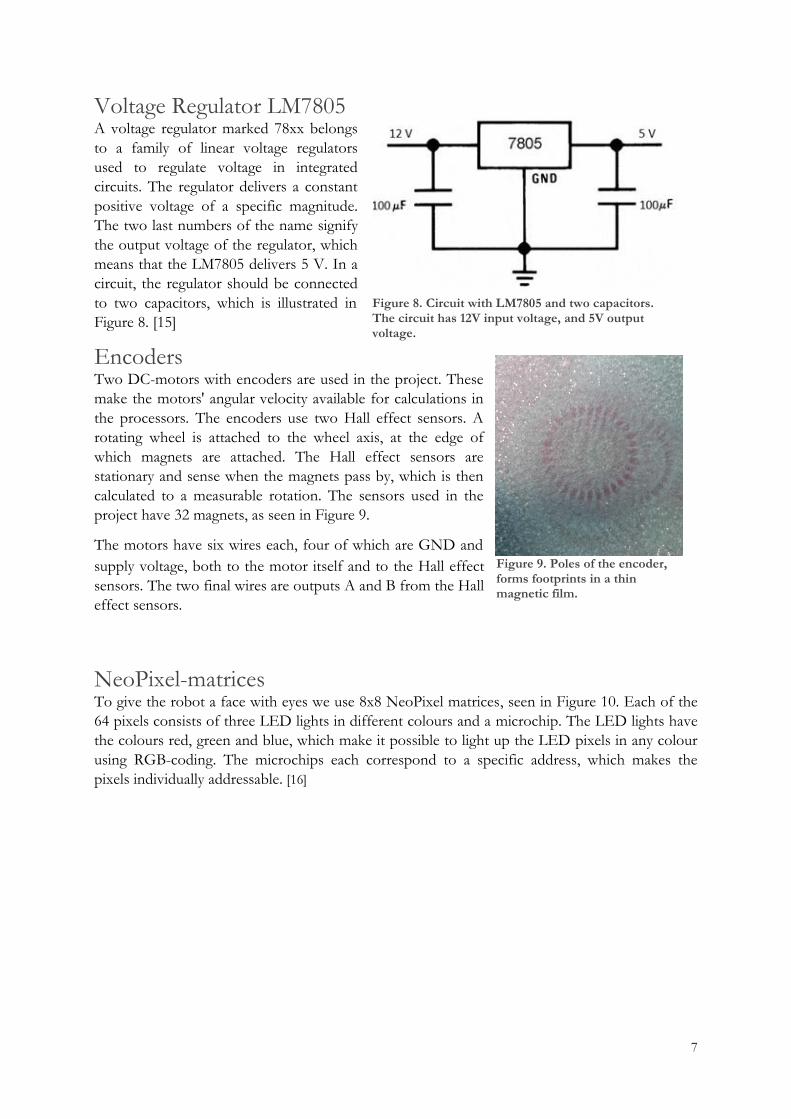
Voltage Regulator LM7805 A voltage regulator marked 78xx belongs
to a family of linear voltage regulators
used to regulate voltage in integrated
circuits. The regulator delivers a constant
positive voltage of a specific magnitude.
The two last numbers of the name signify
the output voltage of the regulator, which
means that the LM7805 delivers 5 V. In a
circuit, the regulator should be connected
to two capacitors, which is illustrated in
Figure 8. [15]
Encoders Two DC-motors with encoders are used in the project. These
make the motors' angular velocity available for calculations in
the processors. The encoders use two Hall effect sensors. A
rotating wheel is attached to the wheel axis, at the edge of
which magnets are attached. The Hall effect sensors are
stationary and sense when the magnets pass by, which is then
calculated to a measurable rotation. The sensors used in the
project have 32 magnets, as seen in Figure 9.
The motors have six wires each, four of which are GND and
supply voltage, both to the motor itself and to the Hall effect
sensors. The two final wires are outputs A and B from the Hall
effect sensors.
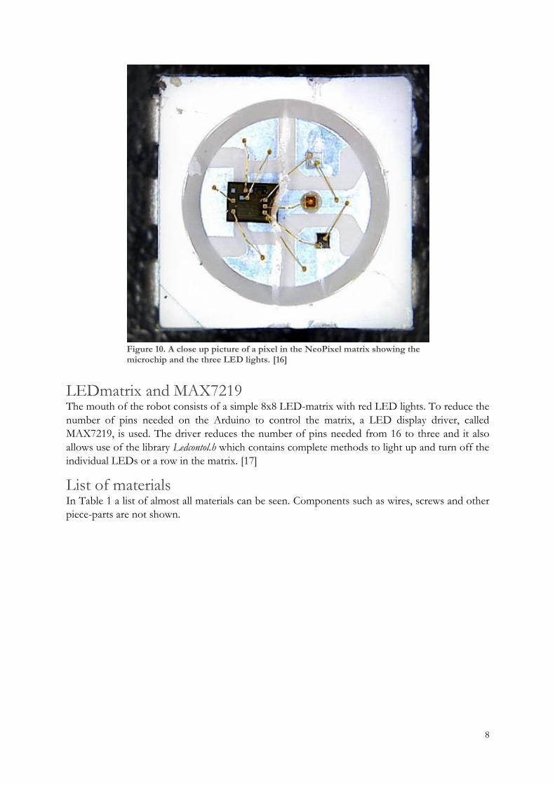
NeoPixel-matrices To give the robot a face with eyes we use 8x8 NeoPixel matrices, seen in Figure 10. Each of the
64 pixels consists of three LED lights in different colours and a microchip. The LED lights have
the colours red, green and blue, which make it possible to light up the LED pixels in any colour
using RGB-coding. The microchips each correspond to a specific address, which makes the
pixels individually addressable. [16]
Figure 8. Circuit with LM7805 and two capacitors. The circuit has 12V input voltage, and 5V output voltage.
8
LEDmatrix and MAX7219 The mouth of the robot consists of a simple 8x8 LED-matrix with red LED lights. To reduce the
number of pins needed on the Arduino to control the matrix, a LED display driver, called
MAX7219, is used. The driver reduces the number of pins needed from 16 to three and it also
allows use of the library Ledcontol.h which contains complete methods to light up and turn off the
individual LEDs or a row in the matrix. [17]
List of materials In Table 1 a list of almost all materials can be seen. Components such as wires, screws and other
piece-parts are not shown.
Figure 10. A close up picture of a pixel in the NeoPixel matrix showing the microchip and the three LED lights. [16]

9
Table 1. List of almost all materials used, as well as cost for each component.
Product: Quantity: Distributor: Price per product, (SEK):
Arduino Starter kit 1 Electrokit 899
Arduino UNO rev. 3 2 Electrokit 215
Arduino Leonardo 1 Electrokit 225
Arduino Motorshield rev. 3 1 Electrokit 295
DC-motor, brushed, 12 V, 29:1 with encoder
2 Sainsmart 192
Battery, NiMH, 12 V 1 Conrad 605
IMU-sensor 1 Electrokit 419
Adafruit NeoPixel-matrix, 8x8 2 Lawicel 399
LED-matrix, 8x8, red 1 Ebay 38
MAX7219 1 Electrokit 95
Voltage regulator, 7805 1 Electrokit 39
LCD-display 1 Electrokit 99
Battery charger for NiMH/NiCd, 12 V
1 Electrokit 299
Precision Wheels, blue 102 mm 1 pair Electrokit 69
Actobotics hubs 0’77 2 Electrokit 49
Pushbutton switches 2 Apem 20
Breadboard pack, small 1 pack Ebay 32
Polycarbonate 3 pcs. 100x200x4 mm
Biltema 18.30
Threaded rod 2 m Clas Ohlson 31.95
Tamiya-connectors 2 Kjell&Co 40
All materials were sponsored by the companies NOW, Conrad, LEAB, Robotdalen, Electrokit,
Syntronic and Apem.
10
Process
Construction From Equation (5), the poles are given by ±√2𝑔/ 𝑙. The pole +√2𝑔/ 𝑙 is unstable. The taller
the robot is, the closer the poles will be to zero, see Figure 2. Thus, the system will be easier to
stabilize. Thus, the robot is designed to be about 50 centimetres tall.
Shelves Three boards of 4 mm thick polycarbonate were cut and the edges were corrected using a milling
machine to 100 by 200 mm. In these boards, 6 mm in diameter holes were drilled 2 cm from the
edges of each corner. Based on the layout of the mounting holes of the Arduino Uno and
Leonardo, 3 mm in diameter holes were drilled into the designated middle shelf. 3 mm holes
were drilled into the lower shelf using the layout of the engine mount (see Engine Mount). On
the middle of each side of the bottom shelf, an 8 mm hole was drilled to pull wires through.
The shelves were assembled by screwing four threaded rods of size M6 through the corner holes.
Engine Mount Two 40x80 mm pieces of sheet metal were cut to be used as mounting plates. On one side, holes
were made to attach to each DC-motor. A larger hole was made for the motor's axis. On the
other side, six 3 mm holes were drilled, corresponding to the holes on the bottom shelf. The
mounting plates were then bent to a 90-degree angle.
The plates were attached to the bottom shelf. Wheels were attached to the plates with hubs made
with a 3D-printer.
Assembly
Arduino Uno, Leonardo and Motor Shield An Arduino Uno was mounted on the middle shelf. The Arduino Uno was attached to a mount,
which came with the Arduino, and was screwed into the pre-prepared holes. Arduino Leonardo
was attached to a soft plastic cushion to isolate and protect it and mounted to the shelf. The
Arduino Motor Shield was originally mounted on the Leonardo, but the motor controller
described later replaced it.
The second Arduino Uno is sewn with needle and thread to the backside of the block of
polymeric foam that forms the robot’s head.
Replacement motor controller The Arduino Motor Shield was damaged during testing so that one of the H-bridges was no
longer functional. In its place, the motor controller described in the section H-Bridge was built
with help from our supervisor. It was connected to the Arduino Leonardo with wires; see Figure
5 for pin configuration. The controller was connected to the common GND node, the 12 V
node, and the 5 V pin on the Leonardo. Pin 2 and 3 were connected to the right motor, and 13
and 14 to the left motor. Pin 5, 6, 10 and 11 on the controller connect, in order, to pin 7, 9, 8 and
6 on the Leonardo. These wires are enough to hold the controller in place, which means it does
not need to be glued or otherwise fastened to anything else.

11
Motors The motors were mounted on the metal plates. The motor wires were equipped with DuPont-
connections to reduce the risk of damage and wear. The ends of the wires were equipped with
male connections for easier use on connection boards. V+ and V- for the motors were connected
to the outputs on the motor controller. The Hall effect sensor is supplied with 5 V from another
node. Output A and B are connected to the (encoder) Arduino Uno.
Batteries The batteries were attached to the bottom shelf using cable ties. The connection cables were
equipped with Tamiya-connectors to match the connectors on the battery charger. Smaller wires
were attached to the ends of the battery wires and connected to the circuit.
Breadboards The breadboards were attached to the shelves by their adhesive backside. One bigger breadboard
was attached to the underside of the middle shelf and a smaller one to the upper side between the
Arduino boards.
IMU-sensor The IMU-sensor was mounted on the lower breadboard. It was supplied with 5 V from a node in
the circuit, and was connected to the common GND node. SCL and SDA were connected to an
I2C-node, which also connects the Arduino Leonardo to the (encoder) Uno.
LED-Matrices The LED matrix and the NeoPixel matrices were sewn with needle and thread to a block of
polymeric foam functioning as the head of the robot. The wires were drawn straight through the
polymeric foam, and connected to the breadboard and the Arduino attached to the backside of
the head. The head was then attached to the rest of the robot by cable ties around the upper
shelf.
Diode “antennas” Two blue light emitting diodes were soldered to wires and taped to the cable ties holding up the
head. The wires were then connected to the 5 V node of the upper circuit via two 100 Ω
resistors.
Pushbutton Switches To simplify the starting process two latching pushbutton switches with LED indication were
added to both the face circuit and the main circuit. The buttons were connected directly to the
battery for switching off all power to the circuits.
Chassis The chassis is made out of firm polymeric foam and is mounted on the front and on the back to
prevent damaging the robot in case of falling. The front part is arched over the wires on the
lower and middle shelf, looking like a belly on the robot. To protect the upper circuit a bigger
block of polymeric foam is mounted on the backside of the head.
12
Troubleshooting When a component doesn’t work immediately, it’s often a good idea to look at the electrical
signals and follow them to see where the problem is. Sometimes, this can be done directly with a
digital multimeter. Other times, one may need to look at the code or the communications more
closely.
Using an oscilloscope Devices connected by I2C communicate in ones and zeroes. Using probes connected to an
oscilloscope, one probe on the SCL and one on the SDA, these can be viewed as high or low
levels. Using this method, it’s possible to ascertain that there is communication and that it looks
reasonable.
In the code When running sketches with the Arduino still connected to the USB port, the Serial Monitor can
be used to read messages from the Arduino. These messages are sent by writing the line
Serial.println() into the code, along with a message or a value to be written out. This
method can be used to find errors in the code. Another helpful line is while(!Serial) which
can keep the code from progressing until the monitor is started. This is a good way to not miss
any messages when debugging.
Programming All the programming is written in the language C and in Arduino's own environment and
software, Arduino IDE. To simplify coding, Arduino has a number of libraries one can include in
order to get complete methods for controlling specific kind of slaves.
Each Arduino sketch consists of one setup section which runs every time the Arduino starts or
gets reset, and one loop section which runs over and over as long as the Arduino is on. Aside
from that, one can write more methods to later run in the loop.
Test code Before connecting it all together several test codes were run to check if the individual
components worked as expected.
IMU-sensor Before connecting the IMU-sensor to the circuit a simulation was run using the software
Processing 3. The test code reads the position in the X, Y and Z- directions from the IMU-
sensor and shows the result as a digital model on the screen. This test worked with our sensor.
Motors A sketch was uploaded where instead of getting motor speeds from a calculation of the angle, the
motor looped trough code that made the motors run forward, stop and run backward. This
experiment had to be repeated while the circuit was corrected until both the forward and
backward direction gave the correct result. The forward and backward direction also had to be
defined in opposite ways on the left and right motor, as the layout of the robot pointed them in
opposite directions.
13
Arduino Leonardo The Arduino Leonardo is the main computer of the circuit and runs the main code.4
Leonardo.ino The main calculations are done in this sketch. In the setup, PWM and direction pins are activated
as inputs or outputs, and directions are defined in terms of motor polarity. The line
Wire.begin()starts the I2C. The line mpu.initialize() starts the code that will read the
IMU. The setup also starts the regulators with the lines initAnglePID() and initSpeedPID().
It also initiates timed actions, which are functions that automatically run methods in a regular
interval, regardless of what else is happening in the code. The methods used in timed actions in
this sketch are for debugging, updating the sensors, and a watchdog that resets the robot when
needed.
In the loop, the first thing that happens is that the watchdog is reset and the timed actions are
checked.5 If the robot is started, it will compute the speed PID, and the output will be used as
setpoint for the next step. The next lines will check if the motors run at different speeds and
calibrate them to move more similarly. The following if-clause checks if the current reading from
the IMU-sensor lies within the limit for conservative parameters, and otherwise uses more
aggressive parameters for the angle PID. After this, the angle PID is computed and finally the
method moveMotor()can be used. This method is contained in the code Motors.ino below.
The first time the loop runs, or if the robot has been stopped, the Boolean started is false. In
this case, the regulators and timed actions are re-initialized and started is set to true.
Finding regulator parameters The main code includes two PID-regulators, one of which has two sets of parameters. In total,
this amounts to nine regulator parameters. These can be calculated theoretically, but the more
efficient method with the best result is to adjust the parameters manually until the desired
behaviour is achieved. First, the conservative parameters for the angle PID give the robot its
basic function of balancing. 𝐾𝑃 is adjusted until the robot oscillates in approximately the same
place without falling over. 𝐾𝐷 should be increased until the robot is no longer oscillating. When
the oscillations stopped, 𝐾𝑃 was adjusted until oscillation started again. Then 𝐾𝐷 was adjusted to
eliminate the oscillations. These two steps were repeated until the system was at the stability limit.
Lastly, 𝐾𝐼 was added to eliminate the remaining error and the parameters adjusted to improve the
behaviour. The speed PID was adjusted the same way, first adding 𝐾𝑃 to stop the drifting,
dampening using 𝐾𝐷, and removing errors using 𝐾𝐼.
The aggressive parameters were set using the method described above, while deactivating the
conservative parameters. The aggressive parameters are actualised by a part of the code if the tilt
exceeds a certain limit. With no conservative parameters, the robot will only use the motors when
the angle is beyond the limit, and use the aggressive parameters. Using this setup, parameters
were once again found which would keep the robot balanced, if less smoothly than before.
4 All code for Arduino Leonardo and both Arduino Unos can be found in Appendix I: - Appendix IV. 5 Debug is only checked if debugging is activated.
14
Alternative way of finding regulator parameters An alternative way of finding the PID parameters using MATLAB & SIMULINK was done. A
model of the system was constructed [18]. With these tools, a desired reference signal could be
obtained.
Motors.ino Motors.ino has also been uploaded to the Leonardo and contains methods for communicating with
the motors. The method moveMotor(int motor, double speed) calculates the PWM and dir
to get the desired speed and direction, and sends this to the motors. The line
digitalWrite(pin, HIGH/LOW) sets the direction and the line analogWrite(pin, value)
the speed, where pin is the pin connected to the motor controller, and value is a value between 0
and 255.
The method updateMotorStatuses()requests information about the motors from the
(encoder) Arduino Uno through the I2C, and updates the associated variables. There is also a
method stopMotors()which sets left and right motor speeds to zero.
Arduino Uno (encoder) The primary function of this Arduino Uno is to read data from the motor encoders, calculate the
position, speed and direction of the wheels and send it to the Arduino Leonardo. The sketch
Uno1.ino has been uploaded for this purpose. Uno1.ino includes two timed actions, for debugging
and for updating motor speeds. The setup sets input pins from the encoders and starts the
Arduino on the I2C, and also defines its slave address. The loop only contains lines to check the
timed actions. The method receiveEvent(int bytesReceived) accepts commands, and
requestEvent() sends the motor speeds to the Leonardo. The methods rightEncoder()
and leftEncoder() update motor positions, and the method updateMotorSpeeds() update
the motor speeds using this information.
Arduino Uno (face) The code controlling the face of the robot consists of three sketches, one for the NeoPixel-
matrices, one for the mouth and one to define the colours for the NeoPixels.
Uno2.ino This code controls the eyes and includes the Adafruit libraries Adafruit_GFX.h,
Adafruit_NeoPixel.h and Adafruit_NeoMatrix.h.
The Adafruit_GFX library for Arduino provides a basic syntax and some basic functions for all
types of Adafruit displays, which makes it easier to switch between multiple sorts of Adafruit
products with the same sketch. The library cannot work by itself and must be combined with
another Adafruit library specific to the NeoPixel product one wants to control.
Together with the GFX library the Adafruit_NeoPixel library is used. This library contains
methods for NeoPixel products specifically, for example methods to address a single pixel, light it
up in desired colour or to turn it off.
The last library one must include is the Adafruit_NeoMatrix library. This allows us to address
rows and columns without addressing every single pixel by its coodinates. This library is built on
the Adafruit_Neopixel library and reuses methods from it, but is adjusted for the use of a matrix
instead of a strip of pixels.
15
To be able to make different facial expressions a number of new methods were written and then
used in the loop. The following methods were added to the sketch:
- maxieAngry() expresses angry red eyes.
- maxieNeural() gives the robot normal neutral eyes.
- maxieBlink() blinks with one eye.
- maxieLeftRight() makes the robot look from one side to the other.
- smallHeart() displays a small pink heart on the matrix eyes.
- bigHeart() displays a big pink heart on the matrix eyes.
All new methods were put in the loop and the different expressions were displayed during a
random period of time, using the function random(int maxvalue) on the delay time between
the facial expressions.
RGB.h To light up a pixel in a specific colour the RGB colour coding system is used, where each existing
colour corresponds to a three digit address.
To get easy access to specific colours, a struct consisting of tree values, r, g and b, were added to a
new tab in the sketch, called RBG.h. The colours that will be frequently used in our sketch are
predefined in the struct and can thereby be accessed easily by a variable name instead of an
address.
Mouth.h The sketch Mouth.h controls the LED-matrix that is the robot’s mouth. For easy programming,
the library Ledcontrol.h was included. The library contains methods to light up or turn off a
single LED light, or a whole row or column in the matrix.
Three methods were added to the sketch, each for one mouth expression.
- happy() displays a smiling mouth.
- muchhappy() displays a mouth with a bigger smile.
- sad() displays a sad mouth.
- neutral() displays a neutral mouth.
The expressions were added to the loop in Uno2.h to match the mouth movement with the eyes’
expressions.
16
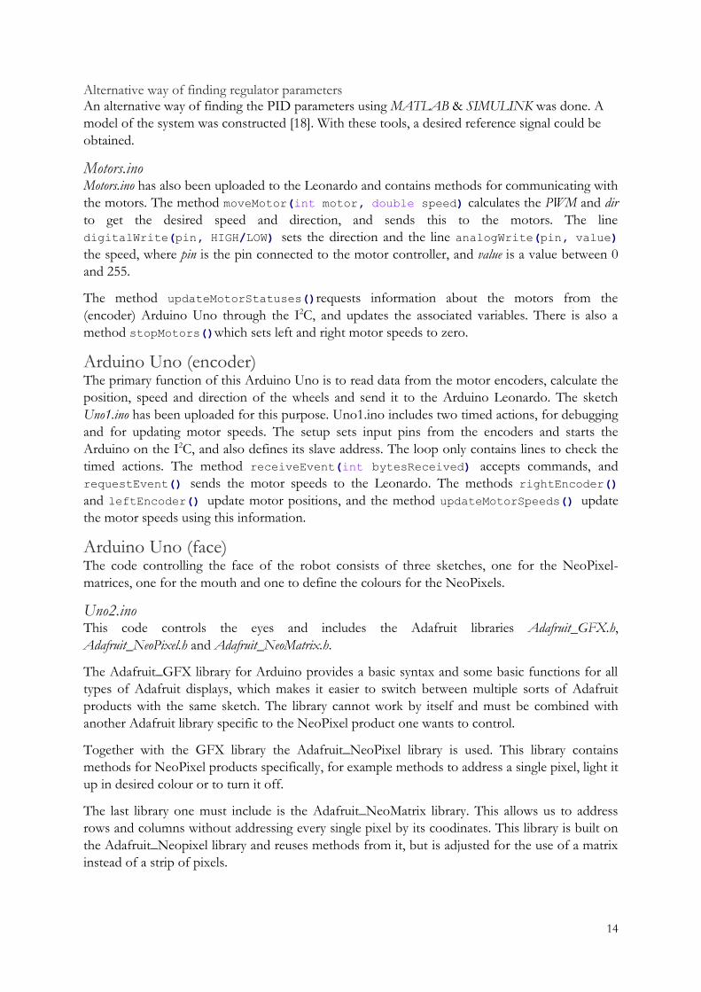
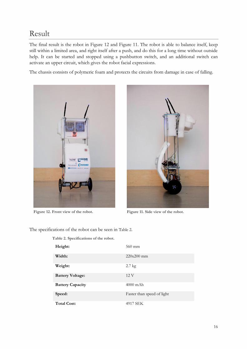
Figure 12. Front view of the robot. Figure 11. Side view of the robot.
Result
The final result is the robot in Figure 12 and Figure 11. The robot is able to balance itself, keep
still within a limited area, and right itself after a push, and do this for a long time without outside
help. It can be started and stopped using a pushbutton switch, and an additional switch can
activate an upper circuit, which gives the robot facial expressions.
The chassis consists of polymeric foam and protects the circuits from damage in case of falling.
The specifications of the robot can be seen in Table 2.
Table 2. Specifications of the robot.
Height: 560 mm
Width: 220x200 mm
Weight: 2.7 kg
Battery Voltage: 12 V
Battery Capacity 4000 mAh
Speed: Faster than speed of light
Total Cost: 4917 SEK
17
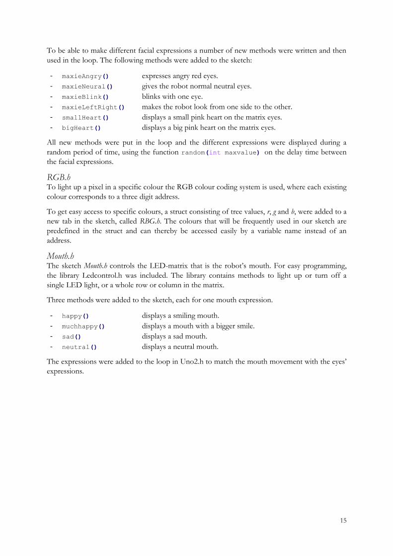
When the main switch is on (seen in the circuit in Figure 13), encoders measure the velocity on
the wheel axes, and an IMU-sensor on the underside of the robot measures the tilt. The velocity
is read by an Arduino Uno and sent through I2C to an Arduino Leonardo. The tilt is read directly
by the Arduino Leonardo through the same I2C. The tilt is filtered and recalculated to degrees.
The speed and tilt are calculated by two cascade-connected regulators into a supply voltage to the
engines.
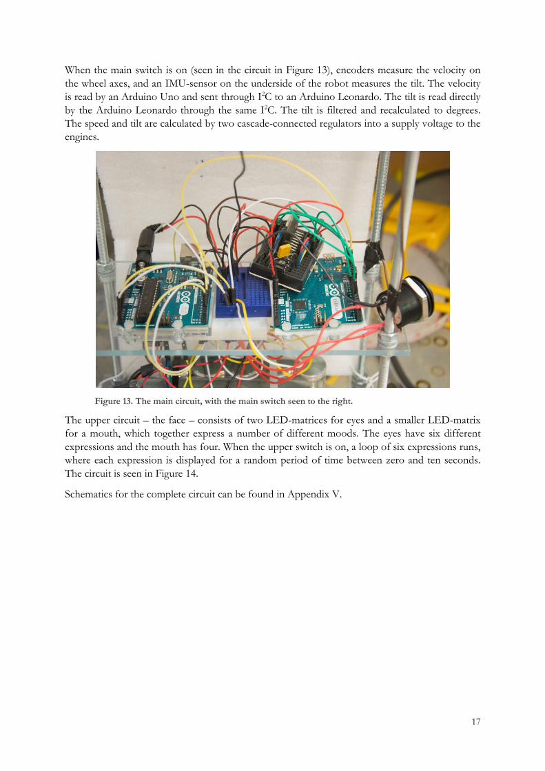
Figure 13. The main circuit, with the main switch seen to the right.
The upper circuit – the face – consists of two LED-matrices for eyes and a smaller LED-matrix
for a mouth, which together express a number of different moods. The eyes have six different
expressions and the mouth has four. When the upper switch is on, a loop of six expressions runs,
where each expression is displayed for a random period of time between zero and ten seconds.
The circuit is seen in Figure 14.
Schematics for the complete circuit can be found in Appendix V.
18
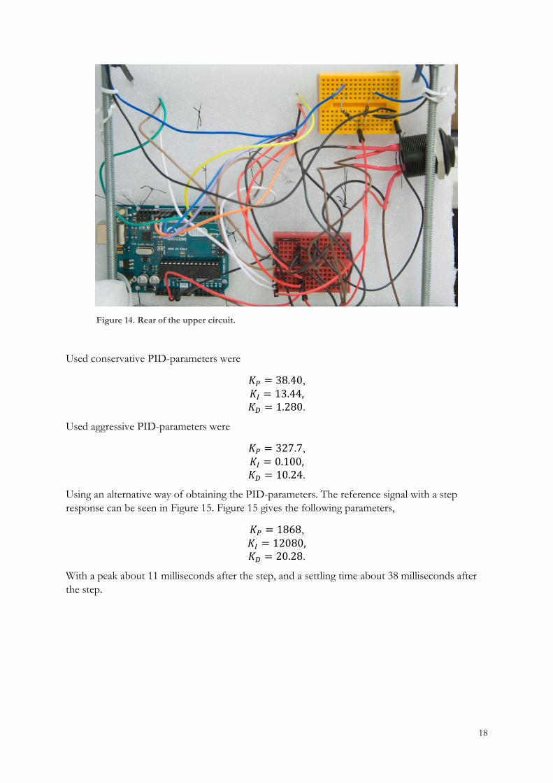
Figure 14. Rear of the upper circuit.
Used conservative PID-parameters were
𝐾𝑃 = 38.40,
𝐾𝐼 = 13.44, 𝐾𝐷 = 1.280.
Used aggressive PID-parameters were
𝐾𝑃 = 327.7,
𝐾𝐼 = 0.100, 𝐾𝐷 = 10.24.
Using an alternative way of obtaining the PID-parameters. The reference signal with a step
response can be seen in Figure 15. Figure 15 gives the following parameters,
𝐾𝑃 = 1868,
𝐾𝐼 = 12080, 𝐾𝐷 = 20.28.
With a peak about 11 milliseconds after the step, and a settling time about 38 milliseconds after
the step.

19
Figure 15. Reference signal with step response, with a peak about 11 milliseconds after the step, and a settling time about 38 milliseconds after step. Both peak, and settling time marked.
The benefits of a filter can be seen in Figure 16.
Figure 16. Complementary filter from the IMU, comparing a filtered signal (blue) with an unfiltered signal (red). Source: [19]
20
Discussion
Microcontrollers Using Arduino as a microcontroller is simple and a good start if you are new to programming and
constructing embedded systems. Though being fast and easy does not come without cost.
Arduino boards are inefficient when it comes to power in relation to its size and price. Most
useful embedded systems do not have much space for the circuit and the electric components. In
fact the microcontroller part of the Arduino takes up less than one tenth of the area of the
Arduino board. The rest of the area is just to simplify wiring and programming but are redundant
to its function if you have the knowledge and understanding of how the microcontroller works.
The microcontroller alone costs a fraction of the price of an Arduino board.
Common Mistakes Current can move in unexpected directions, for example if one component is supplied with 12 V
and is connected to another component, the other component may also get 12 V. If this is then
supplied with 5 V from a node in the circuit, it might instead raise this node to 12 V, damaging
any sensitive components connected to the same node.
An H-bridge should be connected to a motor's V+ and V- directly, the V- end must not be
connected to ground as this will short-circuit the H-bridge.
When using a motor controller, make sure the direction is not changing too often. Too quick
oscillations do not have enough time to work on the motors, but only produce heat in the motor
controller. Check the temperature of the components from time to time.
Jumper wires are practical for making connections and changing them as needed, but do not
always stay in place. Check regularly for wires falling out. Depending on the wire, it could short-
circuit an essential part and damage the components. Jumper cables from the PWM pins on the
Arduino should not come in contact with GND or supply voltage, or the pin on the Leonardo
can be damaged.
Short-circuiting is always a risk, and some things are conductive but easy to overlook. For
example, do not cut both battery cables at once as they will come into contact and the scissors
are conductive.
It is important to find a charger that is appropriate to your battery type. The charger also needs to
have a higher voltage than the batteries.
When coding, there are many easy mistakes to make. If the sketch does not compile because a
method you have written “was not declared in this scope”, check the code for missing or
extra brackets.
Improvements
Steering By changing the setpoint for the speed PID, ideally via a Bluetooth chip, the user would be able
to change the speed of the robot. Steering to the left or right could be added via a method that
brakes one of the motors when a turning method is activated. Alternatively, a pre-programmed
routine could be written. Remote controlling would also be helpful as the robot behaves
differently depending on the battery voltage. Presently, this is solved by changing a variable called
21
moveMotorFactor to match the power, but the code needs to be re-uploaded to the robot in
order to adjust this factor. The ability to adjust it remotely would increase user friendliness.
Parameters The aggressive parameters for the angle PID-regulator described in the programming section are
intended to right the robot when its tilt angle is too big for the conservative parameters to be
effective. The behaviour of the robot depends on these parameters, and finding better parameters
means a better robot. Better aggressive parameters would make the robot better at righting itself
after more violent interference, and create a more stable robot.
Using the parameters obtained with MATLAB (Figure 15) did not manage to balance the robot.
When comparing the conservative PID-parameters with the alternative PID-parameters, one can
see that they do not match very well. However, possible reasons why this did not work and
match well; the model of the system in MATLAB is incorrect, other arrangements of the PID-
parameters gives approximately the same results as desired, but does not work on the Arduino.
For MATLAB code, see section Appendix VI.
Another method called linear quadratic control (LQG) is an alternative to PID-regulators.
Face One improvement for user experience would be to connect the upper Arduino to the two
Arduino boards on the middle shelf, and thereby change the facial expression based on the tilt
angle and the velocity. The robot should then be able to react to whatever happens in the
surroundings and appear more “alive”.
In its current state, the upper Arduino Uno is running on its upper limit when it comes to
handling data. With the NeoPixel matrices there are opportunities for more intricate colour
arrangements, such as sweeping rainbows and fading pixel colours. With a more powerful
microcontroller, more interesting facial expressions could be displayed.
Chassis Originally, the plan was for the chassis to be made using a 3D-printer to get parts exactly as we
wanted them. That would have given us the opportunity to give the robot a more advanced
design with more details. That may also have provided a more solid attachment site for the LED
matrices. However, the polymeric foam chassis used in this robot has the advantage of being free
and do not take time to assemble.
Filters The FIR-filter could be exchanged with a so-called Kalman filter. The Kalman filter will always
give the most optimal filter, and is always stable. We cannot be sure that the FIR-filter is the most
optimal filter, however the filter used is enough to fulfil our purposes. A filtered signal and an
unfiltered signal can be seen in Figure 16.
Wires As it is now, there is a risk of wires loosening from the breadboards. This can cause short-
circuiting and damage pins or other components. A possible solution is to fasten the wires with
plastic wrap. However, one disadvantage of this method is that, if some components get hot, they
will melt the plastic.
22
Conclusion
A robot was constructed and programmed with Arduino technology to balance itself on two
wheels, and display facial expressions. The robot balances with the help of a microcontroller,
which processes data from an IMU-sensor, and two encoders with Hall effect sensors. During
the project we have learnt how to apply our knowledge achieved so far from different courses
such as control theory, electronics and programming combined. The final product can balance
itself as long as no major disturbances occur. Possible improvements include either better PID-parameters or using LQG, better filtering,
steering and wireless control, better chassis, and more secured wires, for example with plastic
wrap.
23
References
[1] A. Allan, “Life Before Arduino,” Make:, vol. 36, no. 36, p. 160, 22 10 2013.
[2] H. Barragán, “The Untold History of Arduino,” Wiring, [Online]. Available:
http://arduinohistory.github.io/. [Accessed 20 May 2016].
[3] M. Richardson, “The March of the Arduino,” Make:, vol. 36, no. 36, p. 160, 22 October 2013.
[4] T. Glad and L. Ljung, Reglerteknik, Upplaga 4:7 ed., Lund: Studentlitteratur AB, 2006.
[5] S. Knorn, “Signaler och system, 5 hp,” 30 July 2015. [Online]. Available:
https://studentportalen.uu.se/portal/portal/uusp/student/filearea?uusp.portalpage=true&mode=fileare
a329798&toolMode=studentUse&entityId=131393&toolAttachmentId=329798. [Accessed 24 May
2016].
[6] T. Hirzel, “PWM,” [Online]. Available: https://www.arduino.cc/en/Tutorial/PWM. [Accessed 18 April
2016].
[7] Starlino, ”Starlino,” 29 December 2009. [Online]. Available: http://www.starlino.com/imu_guide.html.
[Använd 08 April 2016].
[8] Ryan Goodrich, “Accelerometer vs. Gyroscope: What's the Difference?,” Livescience, 01 10 2013.
[Online]. Available: http://www.livescience.com/40103-accelerometer-vs-gyroscope.html. [Accessed 26
April 2016].
[9] Arduino, “Arduino - Environment,” Arduino, 7 September 2015. [Online]. Available:
https://www.arduino.cc/en/Guide/Environment#toc10. [Accessed 25 May 2016].
[10] Arduino, “https://www.arduino.cc/,” 2016. [Online]. Available:
https://www.arduino.cc/en/Main/ArduinoBoardUno. [Accessed 26 April 2016].
[11] Arduino, “https://www.arduino.cc/,” 2016. [Online]. Available:
https://www.arduino.cc/en/Main/arduinoBoardLeonardo. [Accessed 26 April 2016].
[12] Arduino, “https://www.arduino.cc/,” 2016. [Online]. Available:
https://www.arduino.cc/en/Main/ArduinoMotorShieldR3. [Accessed 26 April 2016].
[13] U. Zimmermann, Interviewee, [Interview]. 9 May 2016.
[14] “Invensense,” [Online]. Available: http://www.invensense.com/products/motion-tracking/6-axis/mpu-
6050/. [Accessed 08 April 2016].
[15] TEXAS INSTRUMENTS, “78xx,” 2015. [Online]. Available:
https://www.google.se/url?sa=t&rct=j&q=&esrc=s&source=web&cd=1&cad=rja&uact=8&ved=0ahU
KEwiDveLF0KfNAhWFWCwKHXt0AOoQFggdMAA&url=http%3A%2F%2Fwww.ti.com%2Fcn%2
Flit%2Fgpn%2Flm7805c&usg=AFQjCNH16Sdsrhuz760uay-
CInQnpyVeHQ&sig2=kfg5YoeOIhhyUNE_by4a1g. [Accessed 26 April 2016].
[16] P. Burgess, “The Magic of Neopixel,” Adafruit, 30 August 2013. [Online]. Available:
https://learn.adafruit.com/adafruit-neopixel-uberguide/overview. [Accessed 16 May 2016].
[17] Arduino, “Arduino Playground,” Arduino, [Online]. Available:
http://playground.arduino.cc/Main/LedControl. [Accessed 25 May 2016].

24
[18] C. T. f. M. &. Simulink, “Inverted Pendulum: System Modeling,” Control Tutorials for Matlab &
Simulink, [Online]. Available:
http://ctms.engin.umich.edu/CTMS/index.php?example=InvertedPendulum§ion=SystemModeling.
[Accessed 09 June 2016].
[19] U. Author, “ARDUINO SENSORS,” Unknown Production Company, 10 April 2015. [Online].
Available: https://sourcelion.wordpress.com/2015/04/10/arduino-sensors/. [Accessed 09 June 2016].
[20] DrIguana, “Dr Iguana's Vivarium,” 2012. [Online]. Available: http://www.dr-
iguana.com/prj_marchbreakrobot2012/page2.html. [Accessed 18 May 2016].
[21] ST, “Home - STMicroelectronics,” Januari 2000. [Online]. Available:
http://www.st.com/content/st_com/en/products/motor-drivers/brushed-dc-motor-
drivers/l298.html#samplebuy-scroll. [Accessed 18 May 2016].

i
Appendix
Appendix I:
Main code
Leonardo.ino /*
*
* Copyright (c) 2016 Johanna Blomstedt, Jonathan Haraldsson & Julia Nordin
* Code for the Arduino Leonardo.
*
* Changelog:
* 2016-05-18 - Released first version.
*
*/
#include <I2Cdev.h>
#include <MPU6050_6Axis_MotionApps20.h>
#include <PID_v1.h> //github.com/mwoodward/Arduino-PID-Library
#include <Wire.h> // for i2c
#include <TimedAction.h> // for updating sensors and debug
#include <avr/wdt.h> // watchdog
#include <FIR.h> //github.com/sebnil/FIR-filter-Arduino-Library
#include <MovingAverageFilter.h> //github.com/sebnil/Moving-Avarage-Filter--Arduino-Library-
MPU6050 mpu;
#define OUTPUT_READABLE_YAWPITCHROLL
#define INTERRUPT_PIN 2 // Not currently used
#define LED_PIN 13 // (Arduino is 13)
bool blinkState = false;
// MPU control/status vars
bool dmpReady = false; // set true if DMP init was successful
uint8_t mpuIntStatus; // holds actual interrupt status byte from MPU
uint8_t devStatus; // return status after each device operation (0 = success, !0 = error)
uint16_t packetSize; // expected DMP packet size (default is 42 bytes)
uint16_t fifoCount; // count of all bytes currently in FIFO
uint8_t fifoBuffer[64]; // FIFO storage buffer
// orientation/motion vars
Quaternion q; // [w, x, y, z] quaternion container
VectorInt16 aa; // [x, y, z] accel sensor measurements
VectorInt16 aaReal; // [x, y, z] gravity-free accel sensor measurements
VectorInt16 aaWorld; // [x, y, z] world-frame accel sensor measurements
VectorFloat gravity; // [x, y, z] gravity vector
float euler[3]; // [psi, theta, phi] Euler angle container
float ypr[3]; // [yaw, pitch, roll] yaw/pitch/roll container and gravity vector
float imuValues[6];
float roll;
volatile bool mpuInterrupt = false; // indicates whether MPU interrupt pin has gone high
void dmpDataReady()
mpuInterrupt = true;
boolean debug = false;
boolean started = false;
ii
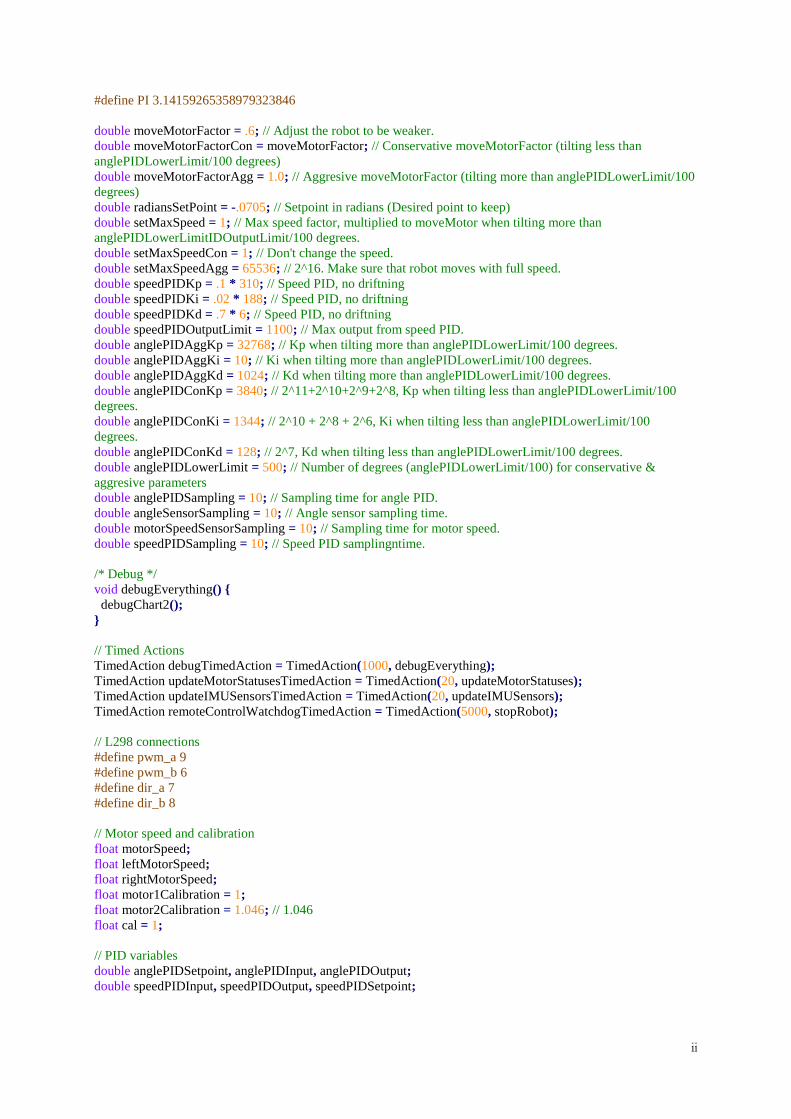
#define PI 3.14159265358979323846
double moveMotorFactor = .6; // Adjust the robot to be weaker.
double moveMotorFactorCon = moveMotorFactor; // Conservative moveMotorFactor (tilting less than
anglePIDLowerLimit/100 degrees)
double moveMotorFactorAgg = 1.0; // Aggresive moveMotorFactor (tilting more than anglePIDLowerLimit/100
degrees)
double radiansSetPoint = -.0705; // Setpoint in radians (Desired point to keep)
double setMaxSpeed = 1; // Max speed factor, multiplied to moveMotor when tilting more than
anglePIDLowerLimitIDOutputLimit/100 degrees.
double setMaxSpeedCon = 1; // Don't change the speed.
double setMaxSpeedAgg = 65536; // 2^16. Make sure that robot moves with full speed.
double speedPIDKp = .1 * 310; // Speed PID, no driftning
double speedPIDKi = .02 * 188; // Speed PID, no driftning
double speedPIDKd = .7 * 6; // Speed PID, no driftning
double speedPIDOutputLimit = 1100; // Max output from speed PID.
double anglePIDAggKp = 32768; // Kp when tilting more than anglePIDLowerLimit/100 degrees.
double anglePIDAggKi = 10; // Ki when tilting more than anglePIDLowerLimit/100 degrees.
double anglePIDAggKd = 1024; // Kd when tilting more than anglePIDLowerLimit/100 degrees.
double anglePIDConKp = 3840; // 2^11+2^10+2^9+2^8, Kp when tilting less than anglePIDLowerLimit/100
degrees.
double anglePIDConKi = 1344; // 2^10 + 2^8 + 2^6, Ki when tilting less than anglePIDLowerLimit/100
degrees.
double anglePIDConKd = 128; // 2^7, Kd when tilting less than anglePIDLowerLimit/100 degrees.
double anglePIDLowerLimit = 500; // Number of degrees (anglePIDLowerLimit/100) for conservative &
aggresive parameters
double anglePIDSampling = 10; // Sampling time for angle PID.
double angleSensorSampling = 10; // Angle sensor sampling time.
double motorSpeedSensorSampling = 10; // Sampling time for motor speed.
double speedPIDSampling = 10; // Speed PID samplingntime.
/* Debug */
void debugEverything()
debugChart2();
// Timed Actions
TimedAction debugTimedAction = TimedAction(1000, debugEverything);
TimedAction updateMotorStatusesTimedAction = TimedAction(20, updateMotorStatuses);
TimedAction updateIMUSensorsTimedAction = TimedAction(20, updateIMUSensors);
TimedAction remoteControlWatchdogTimedAction = TimedAction(5000, stopRobot);
// L298 connections
#define pwm_a 9
#define pwm_b 6
#define dir_a 7
#define dir_b 8
// Motor speed and calibration
float motorSpeed;
float leftMotorSpeed;
float rightMotorSpeed;
float motor1Calibration = 1;
float motor2Calibration = 1.046; // 1.046
float cal = 1;
// PID variables
double anglePIDSetpoint, anglePIDInput, anglePIDOutput;
double speedPIDInput, speedPIDOutput, speedPIDSetpoint;

iii
// The cascading PIDs. The tunings are updated from the code
PID anglePID(&anglePIDInput, &anglePIDOutput, &anglePIDSetpoint, 0, 0, 0, REVERSE); // Kp, Ki, Kd
PID speedPID(&speedPIDInput, &speedPIDOutput, &speedPIDSetpoint, 0, 0, 0, DIRECT); // Kp, Ki, Kd
// Filters
FIR rollFIR;
FIR speedFIR;
MovingAverageFilter speedMovingAverageFilter(40);
MovingAverageFilter throttleControlAverageFilter(40);
// Begin setup
void setup()
Serial.begin(9600);
Serial.println("setup");
//Set control pins to be outputs
pinMode(pwm_a, OUTPUT);
pinMode(pwm_b, OUTPUT);
pinMode(dir_a, OUTPUT);
pinMode(dir_b, OUTPUT);
pinMode(INTERRUPT_PIN, INPUT);
pinMode(LED_PIN, OUTPUT);
digitalWrite(dir_a, LOW);
digitalWrite(dir_b, HIGH);
// Stop the motors if they are running
stopMotors();
// Initialize I2C and IMU
Serial.println("Initialising wire");
Wire.begin(); // Start I2C
Wire.setClock(400000); // Set frequency
delay(5);
Serial.println("Loading IMU");
mpu.initialize(); //begin the IMU
delay(5);
Serial.println("IMU ready");
// load and configure the DMP
Serial.println(F("Initializing DMP..."));
devStatus = mpu.dmpInitialize();
// Gyro offsets
mpu.setXGyroOffset(0);
mpu.setYGyroOffset(0);
mpu.setZGyroOffset(0);
mpu.setZAccelOffset(1688); // 1688 factory default for my test chip
if (devStatus == 0)
// turn on the DMP, now that it's ready
Serial.println(F("Enabling DMP..."));
mpu.setDMPEnabled(true);
// enable Arduino interrupt detection
Serial.println(F("Enabling interrupt detection (Arduino external interrupt 0)..."));
attachInterrupt(digitalPinToInterrupt(INTERRUPT_PIN), dmpDataReady, RISING);
mpuIntStatus = mpu.getIntStatus();
// set our DMP Ready flag so the main loop() function knows it's okay to use it
iv
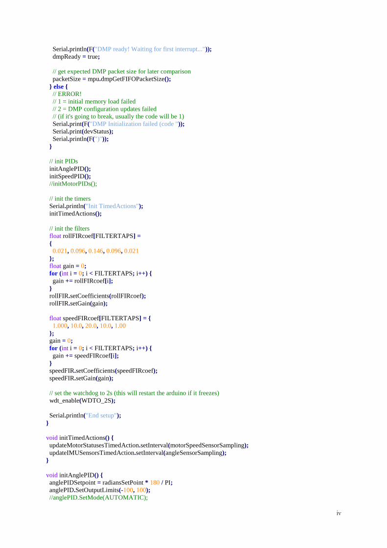
Serial.println(F("DMP ready! Waiting for first interrupt..."));
dmpReady = true;
// get expected DMP packet size for later comparison
packetSize = mpu.dmpGetFIFOPacketSize();
else // ERROR!
// 1 = initial memory load failed
// 2 = DMP configuration updates failed
// (if it's going to break, usually the code will be 1)
Serial.print(F("DMP Initialization failed (code "));
Serial.print(devStatus);
Serial.println(F(")"));
// init PIDs
initAnglePID();
initSpeedPID();
//initMotorPIDs();
// init the timers
Serial.println("Init TimedActions");
initTimedActions();
// init the filters
float rollFIRcoef[FILTERTAPS] =
0.021, 0.096, 0.146, 0.096, 0.021
; float gain = 0;
for (int i = 0; i < FILTERTAPS; i++)
gain += rollFIRcoef[i];
rollFIR.setCoefficients(rollFIRcoef);
rollFIR.setGain(gain);
float speedFIRcoef[FILTERTAPS] =
1.000, 10.0, 20.0, 10.0, 1.00
; gain = 0;
for (int i = 0; i < FILTERTAPS; i++)
gain += speedFIRcoef[i];
speedFIR.setCoefficients(speedFIRcoef);
speedFIR.setGain(gain);
// set the watchdog to 2s (this will restart the arduino if it freezes)
wdt_enable(WDTO_2S);
Serial.println("End setup");
void initTimedActions()
updateMotorStatusesTimedAction.setInterval(motorSpeedSensorSampling);
updateIMUSensorsTimedAction.setInterval(angleSensorSampling);
void initAnglePID()
anglePIDSetpoint = radiansSetPoint * 180 / PI;
anglePID.SetOutputLimits(-100, 100);
//anglePID.SetMode(AUTOMATIC);
v
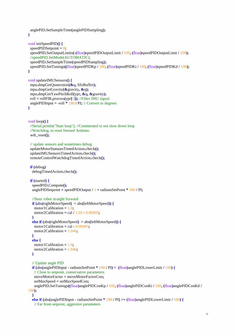
anglePID.SetSampleTime(anglePIDSampling);
void initSpeedPID()
speedPIDSetpoint = 0;
speedPID.SetOutputLimits(-(float)speedPIDOutputLimit / 100, (float)speedPIDOutputLimit / 100);
//speedPID.SetMode(AUTOMATIC);
speedPID.SetSampleTime(speedPIDSampling);
speedPID.SetTunings((float)speedPIDKp / 100, (float)speedPIDKi / 100, (float)speedPIDKd / 100);
void updateIMUSensors()
mpu.dmpGetQuaternion(&q, fifoBuffer);
mpu.dmpGetGravity(&gravity, &q);
mpu.dmpGetYawPitchRoll(ypr, &q, &gravity);
roll = rollFIR.process(ypr[1]); //Filter IMU signal.
anglePIDInput = -roll * 180 / PI; // Convert to degrees
void loop()
//Serial.println("Start loop"); //Commented to not slow down loop
//Watchdog, to reset freezed Arduino.
wdt_reset();
// update sensors and sometimes debug
updateMotorStatusesTimedAction.check();
updateIMUSensorsTimedAction.check();
remoteControlWatchdogTimedAction.check();
if (debug)
debugTimedAction.check();
if (started)
speedPID.Compute();
anglePIDSetpoint = speedPIDOutput / 1 + radiansSetPoint * 180 / PI;
//Steer robot straight forward
if (abs(rightMotorSpeed) < abs(leftMotorSpeed))
motor1Calibration = 1.0;
motor2Calibration = cal / 1.05 - 0.00005;
else if (abs(rightMotorSpeed) > abs(leftMotorSpeed))
motor1Calibration = cal - 0.00005;
motor2Calibration = 1.046;
else motor1Calibration = 1.0;
motor2Calibration = 1.046;
// Update angle PID
if (abs(anglePIDInput - radiansSetPoint * 180 / PI) < (float)anglePIDLowerLimit / 100)
// Close to setpoint, conservative parameters
moveMotorFactor = moveMotorFactorCon;
setMaxSpeed = setMaxSpeedCon;
anglePID.SetTunings((float)anglePIDConKp / 100, (float)anglePIDConKi / 100, (float)anglePIDConKd /
100);
else if (abs(anglePIDInput - radiansSetPoint * 180 / PI) >= (float)anglePIDLowerLimit / 100)
// Far from setpoint, aggresive parameters
vi
moveMotorFactor = moveMotorFactorAgg;
setMaxSpeed = setMaxSpeedAgg;
anglePID.SetTunings((float)anglePIDAggKp / 100, (float)anglePIDAggKi / 100, (float)anglePIDAggKd /
100);
else anglePID.SetTunings(0, 0, 0);
stopMotors();
anglePID.Compute();
moveMotor(1, setMaxSpeed * moveMotorFactor * anglePIDOutput);
moveMotor(2, setMaxSpeed * moveMotorFactor * anglePIDOutput);
else //Serial.println("330 speed 0");
moveMotor(1, 0);
moveMotor(2, 0);
if (!started)
initAnglePID();
initSpeedPID();
initTimedActions();
Serial.println("Starting");
anglePID.SetMode(1);
speedPID.SetMode(1);
started = true;
// MPU6050_6Axis_MotionApps20 example
// if programming failed, don't try to do anything
if (!dmpReady) return;
// wait for MPU interrupt or extra packet(s) available
while (!mpuInterrupt && fifoCount < packetSize)
// reset interrupt flag and get INT_STATUS byte
mpuInterrupt = false;
mpuIntStatus = mpu.getIntStatus();
// get current FIFO count
fifoCount = mpu.getFIFOCount();
// check for overflow (this should never happen unless our code is too inefficient)
if ((mpuIntStatus & 0x10) || fifoCount == 1024)
// reset so we can continue cleanly
mpu.resetFIFO();
Serial.println(F("FIFO overflow!"));
// otherwise, check for DMP data ready interrupt (this should happen frequently)
else if (mpuIntStatus & 0x02)
// wait for correct available data length, should be a VERY short wait
while (fifoCount < packetSize) fifoCount = mpu.getFIFOCount();
// read a packet from FIFO
mpu.getFIFOBytes(fifoBuffer, packetSize);
fifoCount -= packetSize;
vii
// blink LED to indicate activity
blinkState = !blinkState;
digitalWrite(LED_PIN, blinkState);
//END MPU6050_6Axis_MotionApps20 example
//Serial.println("End loop"); //Commented to not slow down loop
// go here if remote control connection is lost
void stopRobot()
Serial.println("stopRobot");
digitalWrite(dir_a, 0);
digitalWrite(dir_b, 0);
void debugChart2()
sendPlotData("rightMotorSpeed", rightMotorSpeed);
sendPlotData("leftMotorSpeed", leftMotorSpeed);
sendPlotData("motorSpeed", motorSpeed);
sendPlotData("speedPIDInput", speedPIDInput);
sendPlotData("speedPIDOutput", speedPIDOutput);
sendPlotData("speedPIDSetpoint", speedPIDSetpoint);
sendPlotData("anglePIDInput", anglePIDInput);
sendPlotData("anglePIDOutput", anglePIDOutput);
sendPlotData("anglePIDSetpoint", anglePIDSetpoint);
void sendPlotData(String seriesName, float data)
Serial.print("");
Serial.print(seriesName);
Serial.print(",T,");
Serial.print(data);
Serial.println("");
void debugConfiguration()
viii
Motors.ino /*
*
* Copyright (c) 2016 Johanna Blomstedt, Jonathan Haraldsson & Julia Nordin
* Code for the Arduino Leonardo.
*
* Changelog:
* 2016-05-18 - Released first version.
*
*/
#define motor1ForwardDir HIGH
#define motor1BackwardDir LOW
#define motor2ForwardDir HIGH
#define motor2BackwardDir LOW
#define maxSpeed 100
#define ENCODERS_I2C_ADDRESS 0x29
#define ENCODERS_I2C_MSG_SIZE 2
char encodersMsg[ENCODERS_I2C_MSG_SIZE];
void updateMotorStatuses()
//Serial.println("Wire.beginTransmission");
Wire.beginTransmission(ENCODERS_I2C_ADDRESS);
//Serial.println("Wire.requestFrom");
Wire.requestFrom(ENCODERS_I2C_ADDRESS, ENCODERS_I2C_MSG_SIZE);
//Serial.println("Wire.endTransmission");
Wire.endTransmission();
for (int i = 0; i <= ENCODERS_I2C_MSG_SIZE; i++)
encodersMsg[i] = Wire.read();
//Serial.println("Wire transmission done");
leftMotorSpeed = (float)encodersMsg[0] * -1;
rightMotorSpeed = (float)encodersMsg[1];
motorSpeed = (leftMotorSpeed + rightMotorSpeed) / 20;
//speedPIDInput = smooth(speedFIR.process(motorSpeed));
speedPIDInput = speedMovingAverageFilter.process(speedFIR.process(motorSpeed));
void stopMotors()
Serial.println("Stop motors");
moveMotor(1, 0); // right
moveMotor(2, 0); // left
Serial.println("END Stop motors");
void moveMotor(int motor, double speed) // speed is a value in percentage 0-100%
//Serial.println("Move motors");
// motor1 is right
// motor2 is left
if (speed > maxSpeed)
speed = maxSpeed;
else if (speed < -maxSpeed)
speed = -maxSpeed;
int pwmToMotor = 0;
if (motor == 1)
pwmToMotor = (abs(speed) * 255 / 100) * motor1Calibration;
else
ix
pwmToMotor = (abs(speed) * 255 / 100) * motor2Calibration;
if (pwmToMotor > 255)
pwmToMotor = 255;
//Serial.println(speed);
//Serial.println(pwmToMotor);
//Serial.println("");
if (motor == 1)
if (speed == 0)
//Serial.println("Motor 1 speed 0");
digitalWrite(dir_a, motor1ForwardDir);
analogWrite(pwm_a, 0);
else if (speed < 0)
//Serial.println("Motor 1 speed < 0");
digitalWrite(dir_a, motor1ForwardDir);
analogWrite(pwm_a, pwmToMotor);
else
//Serial.println("Motor 1 speed > 0");
digitalWrite(dir_a, motor1BackwardDir);
analogWrite(pwm_a, pwmToMotor);
else
if (speed == 0)
//Serial.println("Motor 2 speed 0");
digitalWrite(dir_b, motor2ForwardDir);
analogWrite(pwm_b, 0);
else if (speed < 0)
//Serial.println("Motor 2 speed < 0");
digitalWrite(dir_b, motor2ForwardDir);
analogWrite(pwm_b, pwmToMotor);
else
//Serial.println("Motor 2 speed > 0");
digitalWrite(dir_b, motor2BackwardDir);
analogWrite(pwm_b, pwmToMotor);
//Serial.println("End move motors");
x
Appendix II:
Wheel encoders
Uno1.ino /*
*
* Copyright (c) 2016 Johanna Blomstedt, Jonathan Haraldsson & Julia Nordin
* Code for the Arduino Uno, wheel encoders.
*
* Changelog:
* 2016-04-18 - Released first version.
*
*/
#include "TimedAction.h"
#include <Wire.h>
bool debug = true;
#define speedMultiplier 1
/* I2C */
#define SLAVE_ADDRESS 0x29 //slave address, any number from 0x01 to 0x7F
#define REG_MAP_SIZE 2
#define MAX_SENT_BYTES 3
byte msg[REG_MAP_SIZE];
byte registerMapTemp[REG_MAP_SIZE - 1];
byte receivedCommands[MAX_SENT_BYTES];
/* Encoders */
#define leftEncoder1 2
#define leftEncoder2 4
#define rightEncoder1 3
#define rightEncoder2 5
volatile long leftMotorPosition = 0;
volatile long rightMotorPosition = 0;
long lastLeftMotorPosition = 0;
long lastRightMotorPosition = 0;
int leftMotorSpeed;
int rightMotorSpeed;
int loopCounter = 0;
int lastSpeedUpdate = 0;
int lastDebugEncoders = 0;
void debugEncoders()
Serial.print("Left :");
Serial.println(leftMotorSpeed * speedMultiplier);
Serial.print("Right: ");
Serial.println(rightMotorSpeed * speedMultiplier);
Serial.print(" ");
delay(200);
TimedAction debugEncodersTimedAction = TimedAction(100, debugEncoders);
TimedAction updateMotorSpeedsTimedAction = TimedAction(20, updateMotorSpeeds);
xi
void setup()
delay(5000);
if (debug)
Serial.begin(9600);
/* Setup encoders */
pinMode(leftEncoder1, INPUT);
pinMode(leftEncoder2, INPUT);
pinMode(rightEncoder1, INPUT);
pinMode(rightEncoder2, INPUT);
attachInterrupt(0, leftEncoder, RISING); // pin 2
attachInterrupt(1, rightEncoder, RISING); // pin 3
/* I2C slave init*/
Wire.begin(SLAVE_ADDRESS);
Wire.onRequest(requestEvent);
//Wire.onReceive(receiveEvent);
void requestEvent()
msg[0] = (byte )leftMotorSpeed * speedMultiplier;
msg[1] = (byte )rightMotorSpeed * speedMultiplier;
Wire.write(msg, REG_MAP_SIZE); //Set the buffer up to send all 14 bytes of data
void receiveEvent(int bytesReceived)
for (int a = 0; a < bytesReceived; a++)
if ( a < MAX_SENT_BYTES)
receivedCommands[a] = Wire.read();
else
Wire.read(); // if we receive more data then allowed just throw it away
void updateMotorSpeeds()
leftMotorSpeed = leftMotorPosition - lastLeftMotorPosition;
rightMotorSpeed = rightMotorPosition - lastRightMotorPosition;
lastLeftMotorPosition = leftMotorPosition;
lastRightMotorPosition = rightMotorPosition;
void loop()
if (debug)
debugEncodersTimedAction.check();
updateMotorSpeedsTimedAction.check();
void leftEncoder()
if (PIND & _BV(PIND4)) // read pin 4
leftMotorPosition++;
else leftMotorPosition--;
void rightEncoder()
if (PIND & _BV(PIND5)) // read pin 5

xii
rightMotorPosition++;
else rightMotorPosition--;
xiii
Appendix III:
Face
Uno2.ino /*
*
* Copyright (c) 2016 Johanna Blomstedt, Jonathan Haraldsson & Julia Nordin
* Code for the Arduino Uno, eyes.
*
* Changelog:
* 2016-05-11 - Released first version.
*
*/
#include <Adafruit_GFX.h>
#include <Adafruit_NeoMatrix.h>
#include <Adafruit_NeoPixel.h>
#include "RGB.h"
#include "mouth.h"
#define PIN1 6;
#define PIN2 5;
Adafruit_NeoMatrix matrixL = Adafruit_NeoMatrix(8, 8, 5,
NEO_MATRIX_TOP + NEO_MATRIX_LEFT +
NEO_MATRIX_ROWS + NEO_MATRIX_PROGRESSIVE,
NEO_GRB + NEO_KHZ800);
Adafruit_NeoMatrix matrixH = Adafruit_NeoMatrix(8, 8, 6,
NEO_MATRIX_TOP + NEO_MATRIX_LEFT +
NEO_MATRIX_ROWS + NEO_MATRIX_PROGRESSIVE,
NEO_GRB + NEO_KHZ800);
void setup()
matrixH.begin();
matrixH.setTextWrap(false);
matrixH.setBrightness(10);
matrixH.setTextColor( matrixH.Color(255, 255, 255) );
matrixL.begin();
matrixL.setTextWrap(false);
matrixL.setBrightness(10);
matrixL.setTextColor( matrixL.Color(255, 255, 255) );
lc.shutdown(0,false);
lc.setIntensity(0,8);
lc.clearDisplay(0);
void bigHeart()
matrixL.fillScreen(matrixL.Color(off.r, off.g, off.b));
matrixL.show();
matrixH.fillScreen(matrixH.Color(off.r, off.g, off.b));
matrixH.show();
int logo[8][8] =
0, 0, 0, 0, 0, 0, 0, 0,
0, 1, 0, 0, 0, 1, 0, 0,
1, 1, 1, 0, 1, 1, 1, 0,
1, 1, 1, 1, 1, 1, 1, 0,
xiv
1, 1, 1, 1, 1, 1, 1, 0,
0, 1, 1, 1, 1, 1, 0, 0,
0, 0, 1, 1, 1, 0, 0, 0,
0, 0, 0, 1, 0, 0, 0, 0
;
for(int row = 0; row < 8; row++)
for(int column = 0; column < 8; column++)
if(logo[row][column] == 1)
matrixL.drawPixel(row,column, matrixL.Color(pink.r, pink.g, pink.b));
matrixH.drawPixel(row, column, matrixH.Color(pink.r, pink.g, pink.b));
matrixH.show();
matrixL.show();
void smallHeart()
matrixL.fillScreen(matrixL.Color(off.r, off.g, off.b));
matrixL.show();
matrixH.fillScreen(matrixH.Color(off.r, off.g, off.b));
matrixH.show();
int logo[8][8] =
0,0,0,0,0,0,0,0,
0,0,0,0,0,0,0,0,
0,1,0,0,0,1,0,0,
1,1,1,0,1,1,1,0,
1,1,1,1,1,1,1,0,
0,1,1,1,1,1,0,0,
0,0,1,1,1,0,0,0,
0,0,0,1,0,0,0,0
;
for(int row = 0; row < 8; row++)
for(int column = 0; column < 8; column++)
if(logo[row][column] == 1)
matrixL.drawPixel(row, column, matrixL.Color(pink.r, pink.g, pink.b));
matrixH.drawPixel(row, column, matrixH.Color(pink.r, pink.g, pink.b));
matrixH.show();
matrixL.show();
void maxieAngry()
matrixL.fillScreen(matrixL.Color(off.r, off.g, off.b));
matrixL.show();
matrixH.fillScreen(matrixH.Color(off.r, off.g, off.b));
matrixH.show();
int logoH[8][8] =
0,0,1,1,0,0,0,0,
0,1,1,1,1,0,0,0,
1,1,1,1,1,1,0,0,
1,1,1,1,1,1,1,0,
1,1,1,0,0,1,1,1,
1,1,1,0,0,1,1,1,
0,1,1,1,1,1,1,0,
0,0,1,1,1,1,0,0
;
xv
int logoL[8][8] =
0,0,0,0,1,1,0,0,
0,0,0,1,1,1,1,0,
0,0,1,1,1,1,1,1,
0,1,1,1,1,1,1,1,
1,1,1,0,0,1,1,1,
1,1,1,0,0,1,1,1,
0,1,1,1,1,1,1,0,
0,0,1,1,1,1,0,0
;
for(int row = 0; row < 8; row++)
for(int column = 0; column < 8; column++)
if(logoH[row][column] == 1)
matrixH.drawPixel(row, column, matrixH.Color(red.r, red.g, red.b));
if(logoL[row][column] == 1)
matrixL.drawPixel(row, column, matrixL.Color(red.r, red.g, red.b));
matrixH.show();
matrixL.show();
void maxieBlink()
matrixL.fillScreen(matrixL.Color(off.r, off.g, off.b));
matrixL.show();
matrixH.fillScreen(matrixH.Color(off.r, off.g, off.b));
matrixH.show();
int logoL[8][8] =
0,0,0,0,0,0,0,0,
0,0,0,0,0,0,0,0,
0,0,0,0,0,0,0,0,
1,0,0,0,0,0,0,1,
1,1,0,0,0,0,1,1,
0,1,1,1,1,1,1,0,
0,0,1,1,1,1,0,0,
0,0,0,0,0,0,0,0
; int logoH[8][8] =
0,0,1,1,1,1,0,0,
0,1,1,1,1,1,1,0,
1,1,1,1,1,1,1,1,
1,1,1,0,0,1,1,1,
1,1,1,0,0,1,1,1,
1,1,1,1,1,1,1,1,
0,1,1,1,1,1,1,0,
0,0,1,1,1,1,0,0
;
for(int row = 0; row < 8; row++)
for(int column = 0; column < 8; column++)
if(logoL[row][column] == 1)
matrixL.drawPixel(row, column, matrixL.Color(white.r, white.g, white.b));
if(logoH[row][column] == 1)
matrixH.drawPixel(row, column, matrixH.Color(white.r, white.g, white.b));
xvi
matrixH.show();
matrixL.show();
void maxieNeutral()
matrixL.fillScreen(matrixL.Color(off.r, off.g, off.b));
matrixL.show();
matrixH.fillScreen(matrixH.Color(off.r, off.g, off.b));
matrixH.show();
int logo[8][8] =
0,0,1,1,1,1,0,0,
0,1,1,1,1,1,1,0,
1,1,1,1,1,1,1,1,
1,1,1,0,0,1,1,1,
1,1,1,0,0,1,1,1,
1,1,1,1,1,1,1,1,
0,1,1,1,1,1,1,0,
0,0,1,1,1,1,0,0
;
for(int row = 0; row < 8; row++)
for(int column = 0; column < 8; column++)
if(logo[row][column] == 1)
matrixL.drawPixel(row, column, matrixL.Color(white.r, white.g, white.b));
matrixH.drawPixel(row, column, matrixH.Color(white.r, white.g, white.b));
matrixH.show();
matrixL.show();
void maxieLeftRight()
// This 8x8 array represents the LED matrix pixels.
// A value of 1 means we’ll fade the pixel to white
matrixL.fillScreen(matrixL.Color(off.r, off.g, off.b));
matrixL.show();
matrixH.fillScreen(matrixH.Color(off.r, off.g, off.b));
matrixH.show();
int logo[8][8] =
0,0,1,1,1,1,0,0,
0,1,1,1,1,1,1,0,
1,1,1,1,1,1,1,1,
1,1,1,1,1,0,0,1,
1,1,1,1,1,0,0,1,
1,1,1,1,1,1,1,1,
0,1,1,1,1,1,1,0,
0,0,1,1,1,1,0,0
;
for(int row = 0; row < 8; row++)
for(int column = 0; column < 8; column++)
if(logo[row][column] == 1)
matrixL.drawPixel(row, column, matrixL.Color(white.r, white.g, white.b));
matrixH.drawPixel(row, column, matrixH.Color(white.r, white.g, white.b));
matrixH.show();
matrixL.show();
xvii
delay(1300);
matrixL.drawPixel(3,5, matrixL.Color(white.r, white.g, white.b));
matrixL.drawPixel(3,6, matrixL.Color(white.r, white.g, white.b));
matrixL.drawPixel(4,5, matrixL.Color(white.r, white.g, white.b));
matrixL.drawPixel(4,6, matrixL.Color(white.r, white.g, white.b));
matrixH.drawPixel(3,5, matrixL.Color(white.r, white.g, white.b));
matrixH.drawPixel(3,6, matrixL.Color(white.r, white.g, white.b));
matrixH.drawPixel(4,5, matrixL.Color(white.r, white.g, white.b));
matrixH.drawPixel(4,6, matrixL.Color(white.r, white.g, white.b));
matrixL.drawPixel(3,1, matrixL.Color(off.r, off.g, off.b));
matrixL.drawPixel(3,2, matrixL.Color(off.r, off.g, off.b));
matrixL.drawPixel(4,1, matrixL.Color(off.r, off.g, off.b));
matrixL.drawPixel(4,2, matrixL.Color(off.r, off.g, off.b));
matrixH.drawPixel(3,1, matrixL.Color(off.r, off.g, off.b));
matrixH.drawPixel(3,2, matrixL.Color(off.r, off.g, off.b));
matrixH.drawPixel(4,1, matrixL.Color(off.r, off.g, off.b));
matrixH.drawPixel(4,2, matrixL.Color(off.r, off.g, off.b));
matrixH.show();
matrixL.show();
void loop()
maxieNeutral();
happy();
delay(1000*random(7));
muchhappy();
maxieLeftRight();
delay(1000*random(5));
neutral();
bigHeart();
delay(250);
smallHeart();
delay(250);
bigHeart();
delay(250);
smallHeart();
delay(250);
bigHeart();
delay(250);
smallHeart();
delay(250);
happy();
maxieNeutral();
delay(900);
maxieBlink();
delay(1500);
maxieNeutral();
delay(1000);
sad();
maxieAngry();
delay(1000*random(7));
xviii
RGB.h /*
*
* Copyright (c) 2016 Johanna Blomstedt, Jonathan Haraldsson & Julia Nordin
* Code for the Arduino Uno, eyes.
*
* Changelog:
* 2016-05-11 - Released first version.
*
*/
struct RGB
byte r;
byte g;
byte b;
;
// Define some colors we'll use frequently
RGB white = 255, 255, 255 ;
RGB red = 255, 0, 0 ;
RGB off = 0, 0, 0 ;
RGB blue = 0, 0, 255 ;
RGB pink = 255, 51, 255;

xix
Mouth.h /*
*
* Copyright (c) 2016 Johanna Blomstedt, Jonathan Haraldsson & Julia Nordin
* Code for the Arduino Uno, eyes.
*
* Changelog:
* 2016-05-11 - Released first version.
*
*/
#include <LedControl.h>
#include <binary.h>
#include <Arduino.h>
LedControl lc=LedControl(12,11,10,0); //DIN, CLK, CS
void happy()
lc.clearDisplay(0);
lc.setRow(0,0,B01110000);
lc.setRow(0,1,B00011000);
lc.setRow(0,2,B00001100);
lc.setRow(0,3,B00001100);
lc.setRow(0,4,B00001100);
lc.setRow(0,5,B00001100);
lc.setRow(0,6,B00011000);
lc.setRow(0,7,B01110000);
void sad()
lc.clearDisplay(0);
lc.setRow(0,0,B00011100);
lc.setRow(0,1,B00110000);
lc.setRow(0,2,B01100000);
lc.setRow(0,3,B01100000);
lc.setRow(0,4,B01100000);
lc.setRow(0,5,B01100000);
lc.setRow(0,6,B00110000);
lc.setRow(0,7,B00011100);
void neutral()
lc.clearDisplay(0);
lc.setRow(0,0,B00000000);
lc.setRow(0,1,B00011000);
lc.setRow(0,2,B00011000);
lc.setRow(0,3,B00011000);
lc.setRow(0,4,B00011000);
lc.setRow(0,5,B00011000);
lc.setRow(0,6,B00011000);
lc.setRow(0,7,B00000000);
void muchhappy()
lc.clearDisplay(0);
lc.setRow(0,0,B01110000);
lc.setRow(0,1,B01111000);
lc.setRow(0,2,B00111100);
lc.setRow(0,3,B00111100);
xx
lc.setRow(0,4,B00111100);
lc.setRow(0,5,B00111100);
lc.setRow(0,6,B01111000);
lc.setRow(0,7,B01110000);
xxi
Appendix IV
Test Codes
Imu.ino // I2Cdev library collection - MPU6050 I2C device class, 6-axis MotionApps 2.0 implementation
// Based on InvenSense MPU-6050 register map document rev. 2.0, 5/19/2011 (RM-MPU-6000A-00)
// 5/20/2013 by Jeff Rowberg <[email protected]>
// Updates should (hopefully) always be available at https://github.com/jrowberg/i2cdevlib
//
// Changelog:
// ... - ongoing debug release
/* ============================================
I2Cdev device library code is placed under the MIT license
Copyright (c) 2012 Jeff Rowberg
Permission is hereby granted, free of charge, to any person obtaining a copy
of this software and associated documentation files (the "Software"), to deal
in the Software without restriction, including without limitation the rights
to use, copy, modify, merge, publish, distribute, sublicense, and/or sell
copies of the Software, and to permit persons to whom the Software is
furnished to do so, subject to the following conditions:
The above copyright notice and this permission notice shall be included in
all copies or substantial portions of the Software.
THE SOFTWARE IS PROVIDED "AS IS", WITHOUT WARRANTY OF ANY KIND, EXPRESS OR
IMPLIED, INCLUDING BUT NOT LIMITED TO THE WARRANTIES OF MERCHANTABILITY,
FITNESS FOR A PARTICULAR PURPOSE AND NONINFRINGEMENT. IN NO EVENT SHALL THE
AUTHORS OR COPYRIGHT HOLDERS BE LIABLE FOR ANY CLAIM, DAMAGES OR OTHER
LIABILITY, WHETHER IN AN ACTION OF CONTRACT, TORT OR OTHERWISE, ARISING FROM,
OUT OF OR IN CONNECTION WITH THE SOFTWARE OR THE USE OR OTHER DEALINGS IN
THE SOFTWARE.
===============================================
*/
#include "I2Cdev.h"
#include "MPU6050_6Axis_MotionApps20.h"
#if I2CDEV_IMPLEMENTATION == I2CDEV_ARDUINO_WIRE
#include "Wire.h"
#endif
MPU6050 mpu;
#define OUTPUT_READABLE_YAWPITCHROLL
#define INTERRUPT_PIN 2 // use pin 2 on Arduino Uno & most boards
#define LED_PIN 13 // (Arduino is 13, Teensy is 11, Teensy++ is 6)
bool blinkState = false;
// MPU control/status vars
bool dmpReady = false; // set true if DMP init was successful
uint8_t mpuIntStatus; // holds actual interrupt status byte from MPU
uint8_t devStatus; // return status after each device operation (0 = success, !0 = error)
uint16_t packetSize; // expected DMP packet size (default is 42 bytes)
uint16_t fifoCount; // count of all bytes currently in FIFO
uint8_t fifoBuffer[64]; // FIFO storage buffer
// orientation/motion vars
Quaternion q; // [w, x, y, z] quaternion container
VectorInt16 aa; // [x, y, z] accel sensor measurements
xxii
VectorInt16 aaReal; // [x, y, z] gravity-free accel sensor measurements
VectorInt16 aaWorld; // [x, y, z] world-frame accel sensor measurements
VectorFloat gravity; // [x, y, z] gravity vector
float euler[3]; // [psi, theta, phi] Euler angle container
float ypr[3]; // [yaw, pitch, roll] yaw/pitch/roll container and gravity vector
// packet structure for InvenSense teapot demo
uint8_t teapotPacket[14] = '$', 0x02, 0,0, 0,0, 0,0, 0,0, 0x00, 0x00, '\r', '\n' ;
// ================================================================
// === INTERRUPT DETECTION ROUTINE ===
// ================================================================
volatile bool mpuInterrupt = false; // indicates whether MPU interrupt pin has gone high
void dmpDataReady()
mpuInterrupt = true;
// ================================================================
// === INITIAL SETUP ===
// ================================================================
void setup()
// join I2C bus (I2Cdev library doesn't do this automatically)
#if I2CDEV_IMPLEMENTATION == I2CDEV_ARDUINO_WIRE
Wire.begin();
Wire.setClock(400000); // 400kHz I2C clock. Comment this line if having compilation difficulties
#elif I2CDEV_IMPLEMENTATION == I2CDEV_BUILTIN_FASTWIRE
Fastwire::setup(400, true);
#endif
// initialize serial communication
// (115200 chosen because it is required for Teapot Demo output, but it's
// really up to you depending on your project)
Serial.begin(9600);
while (!Serial); // wait for Leonardo enumeration, others continue immediately
// NOTE: 8MHz or slower host processors, like the Teensy @ 3.3v or Ardunio
// Pro Mini running at 3.3v, cannot handle this baud rate reliably due to
// the baud timing being too misaligned with processor ticks. You must use
// 38400 or slower in these cases, or use some kind of external separate
// crystal solution for the UART timer.
// initialize device
Serial.println(F("Initializing I2C devices..."));
mpu.initialize();
Serial.println(F("Done initializing I2C devices..."));
pinMode(INTERRUPT_PIN, INPUT);
// verify connection
Serial.println(F("Testing device connections..."));
Serial.println(mpu.testConnection() ? F("MPU6050 connection successful") : F("MPU6050 connection
failed"));
// wait for ready
Serial.println(F("\nSend any character to begin DMP programming and demo: "));
while (Serial.available() && Serial.read()); // empty buffer
xxiii
while (!Serial.available()); // wait for data
while (Serial.available() && Serial.read()); // empty buffer again
// load and configure the DMP
Serial.println(F("Initializing DMP..."));
devStatus = mpu.dmpInitialize();
// supply your own gyro offsets here, scaled for min sensitivity
mpu.setXGyroOffset(220);
mpu.setYGyroOffset(76);
mpu.setZGyroOffset(-85);
mpu.setZAccelOffset(1788); // 1688 factory default for my test chip
// make sure it worked (returns 0 if so)
if (devStatus == 0)
// turn on the DMP, now that it's ready
Serial.println(F("Enabling DMP..."));
mpu.setDMPEnabled(true);
// enable Arduino interrupt detection
Serial.println(F("Enabling interrupt detection (Arduino external interrupt 0)..."));
attachInterrupt(digitalPinToInterrupt(INTERRUPT_PIN), dmpDataReady, RISING);
mpuIntStatus = mpu.getIntStatus();
// set our DMP Ready flag so the main loop() function knows it's okay to use it
Serial.println(F("DMP ready! Waiting for first interrupt..."));
dmpReady = true;
// get expected DMP packet size for later comparison
packetSize = mpu.dmpGetFIFOPacketSize();
else // ERROR!
// 1 = initial memory load failed
// 2 = DMP configuration updates failed
// (if it's going to break, usually the code will be 1)
Serial.print(F("DMP Initialization failed (code "));
Serial.print(devStatus);
Serial.println(F(")"));
// configure LED for output
pinMode(LED_PIN, OUTPUT);
// ================================================================
// === MAIN PROGRAM LOOP ===
// ================================================================
void loop()
// if programming failed, don't try to do anything
if (!dmpReady) return;
// wait for MPU interrupt or extra packet(s) available
while (!mpuInterrupt && fifoCount < packetSize)
// other program behavior stuff here
// .
// .
// .
// if you are really paranoid you can frequently test in between other
xxiv
// stuff to see if mpuInterrupt is true, and if so, "break;" from the
// while() loop to immediately process the MPU data
// .
// .
// .
// reset interrupt flag and get INT_STATUS byte
mpuInterrupt = false;
mpuIntStatus = mpu.getIntStatus();
// get current FIFO count
fifoCount = mpu.getFIFOCount();
// check for overflow (this should never happen unless our code is too inefficient)
if ((mpuIntStatus & 0x10) || fifoCount == 1024)
// reset so we can continue cleanly
mpu.resetFIFO();
Serial.println(F("FIFO overflow!"));
// otherwise, check for DMP data ready interrupt (this should happen frequently)
else if (mpuIntStatus & 0x02)
// wait for correct available data length, should be a VERY short wait
while (fifoCount < packetSize) fifoCount = mpu.getFIFOCount();
// read a packet from FIFO
mpu.getFIFOBytes(fifoBuffer, packetSize);
// track FIFO count here in case there is > 1 packet available
// (this lets us immediately read more without waiting for an interrupt)
fifoCount -= packetSize;
#ifdef OUTPUT_READABLE_QUATERNION
// display quaternion values in easy matrix form: w x y z
mpu.dmpGetQuaternion(&q, fifoBuffer);
Serial.print("quat\t");
Serial.print(q.w);
Serial.print("\t");
Serial.print(q.x);
Serial.print("\t");
Serial.print(q.y);
Serial.print("\t");
Serial.println(q.z);
#endif
#ifdef OUTPUT_READABLE_EULER
// display Euler angles in degrees
mpu.dmpGetQuaternion(&q, fifoBuffer);
mpu.dmpGetEuler(euler, &q);
Serial.print("euler\t");
Serial.print(euler[0] * 180/M_PI);
Serial.print("\t");
Serial.print(euler[1] * 180/M_PI);
Serial.print("\t");
Serial.println(euler[2] * 180/M_PI);
#endif
#ifdef OUTPUT_READABLE_YAWPITCHROLL
// display Euler angles in degrees
mpu.dmpGetQuaternion(&q, fifoBuffer);
mpu.dmpGetGravity(&gravity, &q);
xxv
mpu.dmpGetYawPitchRoll(ypr, &q, &gravity);
Serial.print("ypr\t");
Serial.print(ypr[0] * 180/M_PI);
Serial.print("\t");
Serial.print(ypr[1] * 180/M_PI);
Serial.print("\t");
Serial.println(ypr[2] * 180/M_PI);
#endif
#ifdef OUTPUT_READABLE_REALACCEL
// display real acceleration, adjusted to remove gravity
mpu.dmpGetQuaternion(&q, fifoBuffer);
mpu.dmpGetAccel(&aa, fifoBuffer);
mpu.dmpGetGravity(&gravity, &q);
mpu.dmpGetLinearAccel(&aaReal, &aa, &gravity);
Serial.print("areal\t");
Serial.print(aaReal.x);
Serial.print("\t");
Serial.print(aaReal.y);
Serial.print("\t");
Serial.println(aaReal.z);
#endif
#ifdef OUTPUT_READABLE_WORLDACCEL
// display initial world-frame acceleration, adjusted to remove gravity
// and rotated based on known orientation from quaternion
mpu.dmpGetQuaternion(&q, fifoBuffer);
mpu.dmpGetAccel(&aa, fifoBuffer);
mpu.dmpGetGravity(&gravity, &q);
mpu.dmpGetLinearAccel(&aaReal, &aa, &gravity);
mpu.dmpGetLinearAccelInWorld(&aaWorld, &aaReal, &q);
Serial.print("aworld\t");
Serial.print(aaWorld.x);
Serial.print("\t");
Serial.print(aaWorld.y);
Serial.print("\t");
Serial.println(aaWorld.z);
#endif
#ifdef OUTPUT_TEAPOT
// display quaternion values in InvenSense Teapot demo format:
teapotPacket[2] = fifoBuffer[0];
teapotPacket[3] = fifoBuffer[1];
teapotPacket[4] = fifoBuffer[4];
teapotPacket[5] = fifoBuffer[5];
teapotPacket[6] = fifoBuffer[8];
teapotPacket[7] = fifoBuffer[9];
teapotPacket[8] = fifoBuffer[12];
teapotPacket[9] = fifoBuffer[13];
Serial.write(teapotPacket, 14);
teapotPacket[11]++; // packetCount, loops at 0xFF on purpose
#endif
// blink LED to indicate activity
blinkState = !blinkState;
digitalWrite(LED_PIN, blinkState);
xxvi
I2C.ino
// --------------------------------------
// i2c_scanner
//
// Version 1
// This program (or code that looks like it)
// can be found in many places.
// For example on the Arduino.cc forum.
// The original author is not know.
// Version 2, Juni 2012, Using Arduino 1.0.1
// Adapted to be as simple as possible by Arduino.cc user Krodal
// Version 3, Feb 26 2013
// V3 by louarnold
// Version 4, March 3, 2013, Using Arduino 1.0.3
// by Arduino.cc user Krodal.
// Changes by louarnold removed.
// Scanning addresses changed from 0...127 to 1...119,
// according to the i2c scanner by Nick Gammon
// http://www.gammon.com.au/forum/?id=10896
// Version 5, March 28, 2013
// As version 4, but address scans now to 127.
// A sensor seems to use address 120.
//
//
// This sketch tests the standard 7-bit addresses
// Devices with higher bit address might not be seen properly.
//
#include <Wire.h>
void setup()
Wire.begin();
Serial.begin(9600);
Serial.println("\nI2C Scanner");
void loop()
byte error, address;
int nDevices;
Serial.println("Scanning...");
nDevices = 0;
for(address = 1; address < 127; address++ )
//Serial.print("Scanning adress: ");
//Serial.println(address);
// The i2c_scanner uses the return value of
// the Write.endTransmisstion to see if
// a device did acknowledge to the address.
//Serial.println("Begin beginTransmission");
Wire.beginTransmission(address);
xxvii
//Serial.println("End beginTransmission");
//Serial.println("endTransmission");
error = Wire.endTransmission();
//Serial.println("End endTransmission");
//Serial.print("Error: ");
//Serial.println(error);
if (error == 0)
Serial.print("I2C device found at address 0x");
if (address<16)
Serial.print("0");
Serial.print(address,HEX);
Serial.println(" !");
nDevices++;
else if (error==4)
Serial.print("Unknow error at address 0x");
if (address<16)
Serial.print("0");
Serial.println(address,HEX);
if (nDevices == 0)
Serial.println("No I2C devices found\n");
else Serial.println("done\n");
delay(5000); // wait 5 seconds for next scan
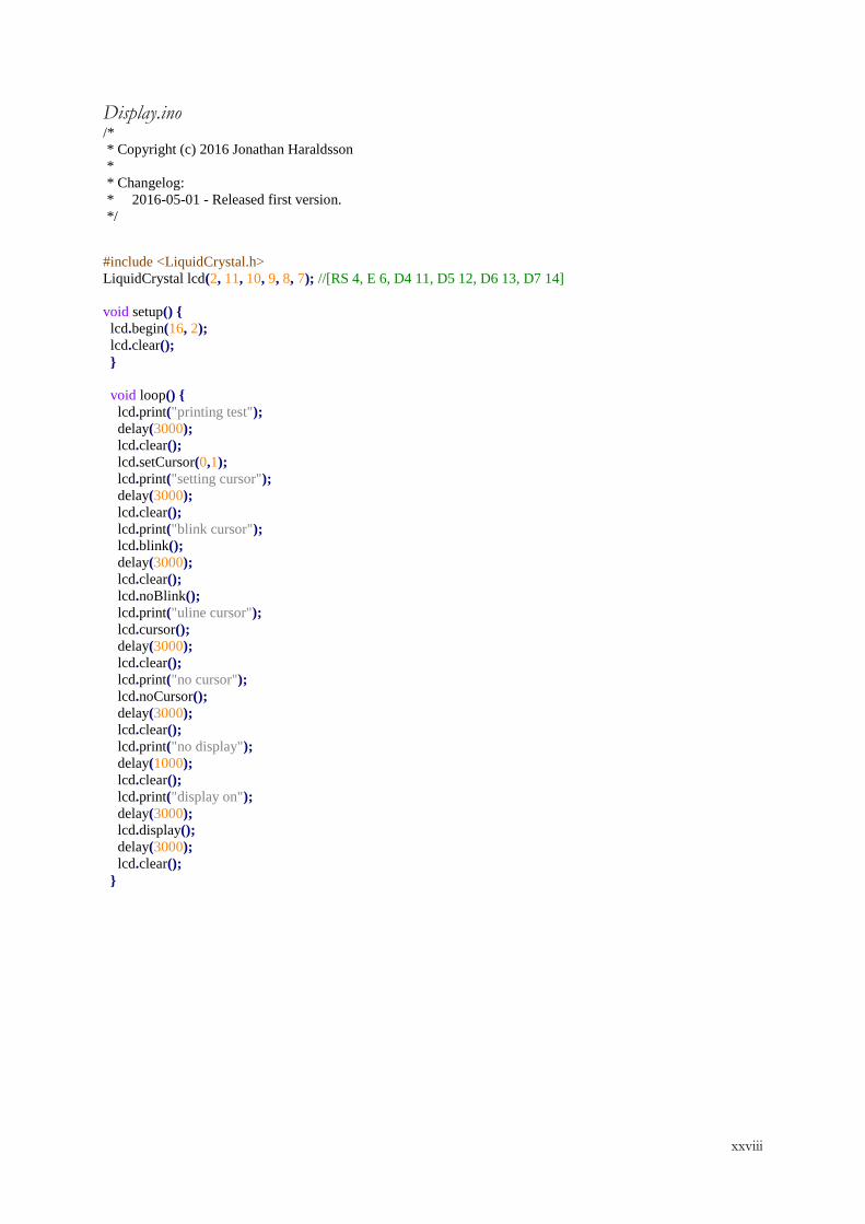
xxviii
Display.ino /*
* Copyright (c) 2016 Jonathan Haraldsson
*
* Changelog:
* 2016-05-01 - Released first version.
*/
#include <LiquidCrystal.h>
LiquidCrystal lcd(2, 11, 10, 9, 8, 7); //[RS 4, E 6, D4 11, D5 12, D6 13, D7 14]
void setup()
lcd.begin(16, 2);
lcd.clear();
void loop()
lcd.print("printing test");
delay(3000);
lcd.clear();
lcd.setCursor(0,1);
lcd.print("setting cursor");
delay(3000);
lcd.clear();
lcd.print("blink cursor");
lcd.blink();
delay(3000);
lcd.clear();
lcd.noBlink();
lcd.print("uline cursor");
lcd.cursor();
delay(3000);
lcd.clear();
lcd.print("no cursor");
lcd.noCursor();
delay(3000);
lcd.clear();
lcd.print("no display");
delay(1000);
lcd.clear();
lcd.print("display on");
delay(3000);
lcd.display();
delay(3000);
lcd.clear();
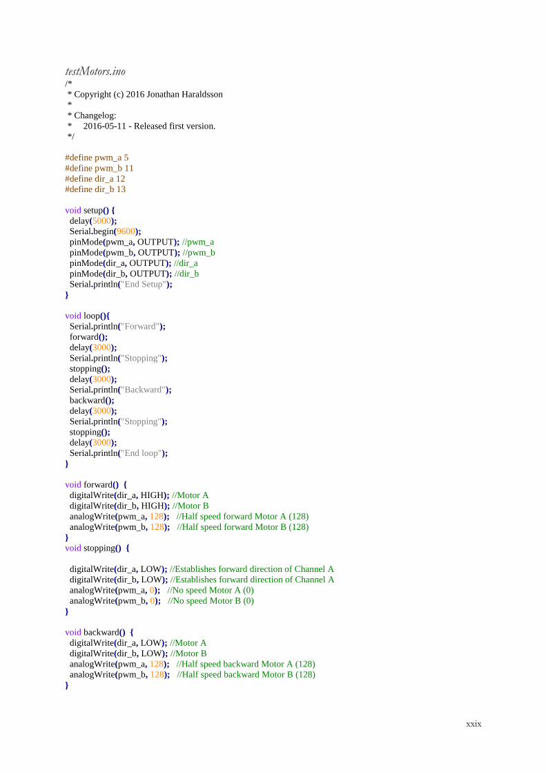
xxix
testMotors.ino /*
* Copyright (c) 2016 Jonathan Haraldsson
*
* Changelog:
* 2016-05-11 - Released first version.
*/
#define pwm_a 5
#define pwm_b 11
#define dir_a 12
#define dir_b 13
void setup()
delay(5000);
Serial.begin(9600);
pinMode(pwm_a, OUTPUT); //pwm_a
pinMode(pwm_b, OUTPUT); //pwm_b
pinMode(dir_a, OUTPUT); //dir_a
pinMode(dir_b, OUTPUT); //dir_b
Serial.println("End Setup");
void loop()
Serial.println("Forward");
forward();
delay(3000);
Serial.println("Stopping");
stopping();
delay(3000);
Serial.println("Backward");
backward();
delay(3000);
Serial.println("Stopping");
stopping();
delay(3000);
Serial.println("End loop");
void forward()
digitalWrite(dir_a, HIGH); //Motor A
digitalWrite(dir_b, HIGH); //Motor B
analogWrite(pwm_a, 128); //Half speed forward Motor A (128)
analogWrite(pwm_b, 128); //Half speed forward Motor B (128)
void stopping()
digitalWrite(dir_a, LOW); //Establishes forward direction of Channel A
digitalWrite(dir_b, LOW); //Establishes forward direction of Channel A
analogWrite(pwm_a, 0); //No speed Motor A (0)
analogWrite(pwm_b, 0); //No speed Motor B (0)
void backward()
digitalWrite(dir_a, LOW); //Motor A
digitalWrite(dir_b, LOW); //Motor B
analogWrite(pwm_a, 128); //Half speed backward Motor A (128)
analogWrite(pwm_b, 128); //Half speed backward Motor B (128)
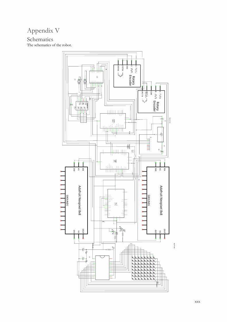
xxx
Appendix V
Schematics The schematics of the robot.
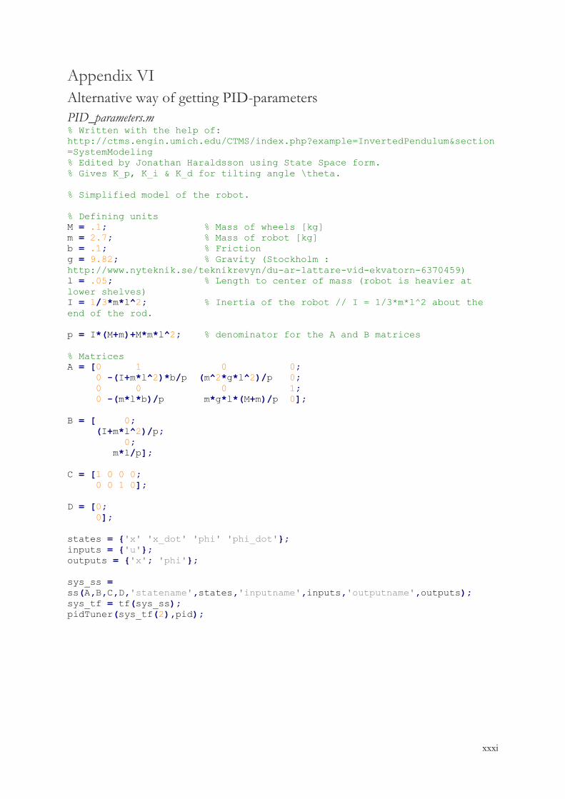
xxxi
Appendix VI
Alternative way of getting PID-parameters
PID_parameters.m % Written with the help of:
http://ctms.engin.umich.edu/CTMS/index.php?example=InvertedPendulum§ion
=SystemModeling
% Edited by Jonathan Haraldsson using State Space form.
% Gives K_p, K_i & K_d for tilting angle \theta.
% Simplified model of the robot.
% Defining units
M = .1; % Mass of wheels [kg]
m = 2.7; % Mass of robot [kg]
b = .1; % Friction
g = 9.82; % Gravity (Stockholm :
http://www.nyteknik.se/teknikrevyn/du-ar-lattare-vid-ekvatorn-6370459)
l = .05; % Length to center of mass (robot is heavier at
lower shelves)
I = 1/3*m*l^2; % Inertia of the robot // I = 1/3*m*l^2 about the
end of the rod.
p = I*(M+m)+M*m*l^2; % denominator for the A and B matrices
% Matrices
A = [0 1 0 0;
0 -(I+m*l^2)*b/p (m^2*g*l^2)/p 0;
0 0 0 1;
0 -(m*l*b)/p m*g*l*(M+m)/p 0];
B = [ 0;
(I+m*l^2)/p;
0;
m*l/p];
C = [1 0 0 0;
0 0 1 0];
D = [0;
0];
states = 'x' 'x_dot' 'phi' 'phi_dot';
inputs = 'u';
outputs = 'x'; 'phi';
sys_ss =
ss(A,B,C,D,'statename',states,'inputname',inputs,'outputname',outputs);
sys_tf = tf(sys_ss);
pidTuner(sys_tf(2),pid);