function - kepic : 방문을 환영합니다. function transporting ... sa-106 grade b carbon steel...
TRANSCRIPT
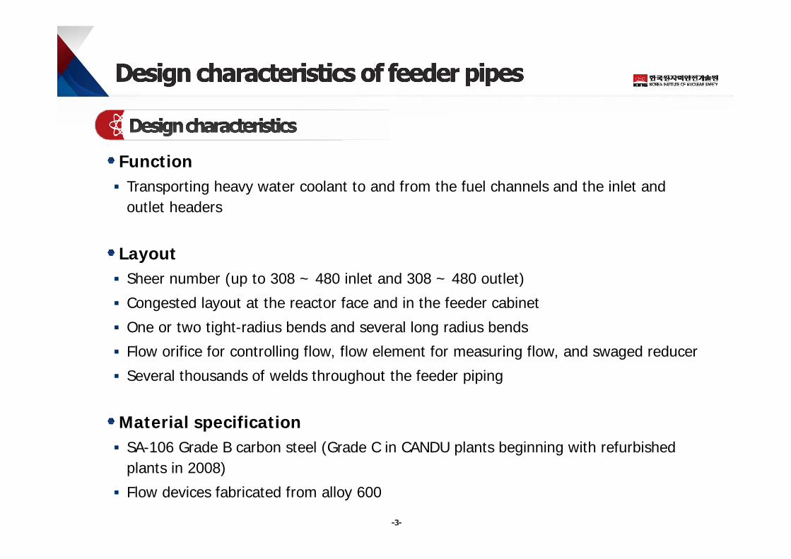
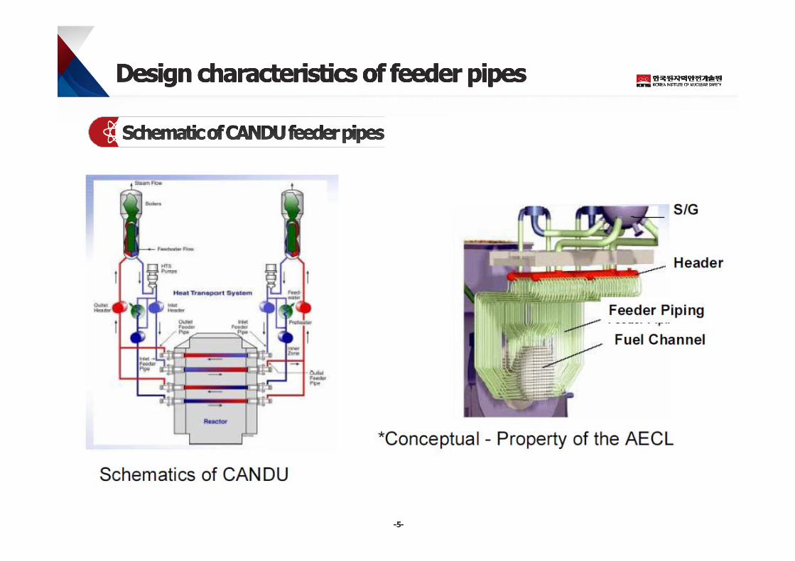
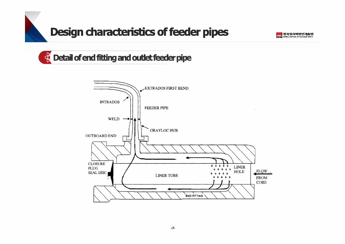
Function Transporting heavy water coolant to and from the fuel channels and the inlet and
outlet headers
Layout Sheer number (up to 308 ~ 480 inlet and 308 ~ 480 outlet)
Congested layout at the reactor face and in the feeder cabinet
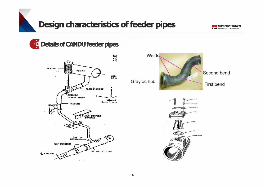
One or two tight-radius bends and several long radius bends
Flow orifice for controlling flow, flow element for measuring flow, and swaged reducer
Several thousands of welds throughout the feeder piping
Material specification SA-106 Grade B carbon steel (Grade C in CANDU plants beginning with refurbished
plants in 2008)
Flow devices fabricated from alloy 600
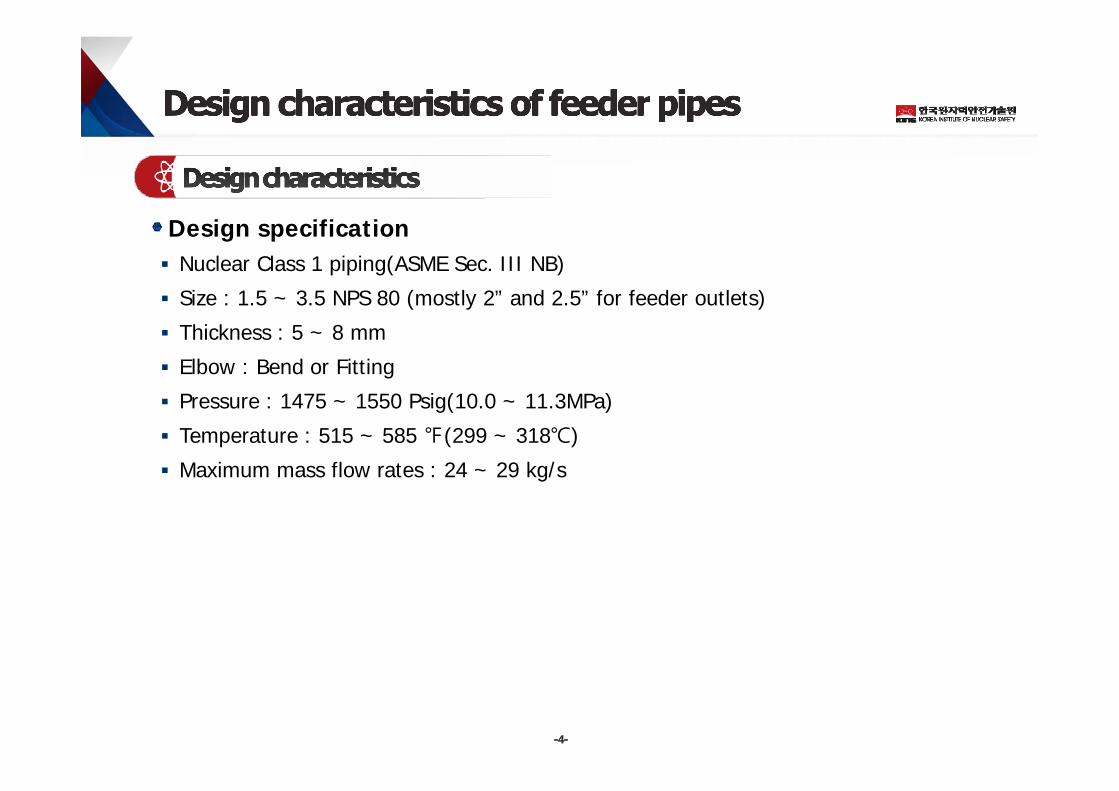
Design specification Nuclear Class 1 piping(ASME Sec. III NB)
Size : 1.5 ~ 3.5 NPS 80 (mostly 2” and 2.5” for feeder outlets)
Thickness : 5 ~ 8 mm
Elbow : Bend or Fitting
Pressure : 1475 ~ 1550 Psig(10.0 ~ 11.3MPa)
Temperature : 515 ~ 585 ℉(299 ~ 318℃)
Maximum mass flow rates : 24 ~ 29 kg/s
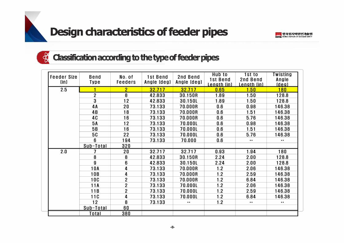
Feeder S ize(in )
BendType
No . ofFeeders
1st BendAngle (deg)
2nd BendAngle (deg)
Hub to1st Bend
Length (in )
1st to2nd BendLength (in )
Tw istingAngle(deg)
2 .5 1 2 32.717 32.717 0.65 1 .50 180
2 8 42.833 30.150R 1.89 1 .50 128.8
3 12 42.833 30.150L 1 .89 1 .50 128.8
4A 20 73.133 70.000R 0.6 0 .98 146.38
4B 18 73.133 70.000R 0.6 1 .51 146.38
4C 16 73.133 70.000R 0.6 5 .76 146.38
5A 12 73.133 70.000L 0 .6 0 .98 146.38
5B 16 73.133 70.000L 0 .6 1 .51 146.38
5C 22 73.133 70.000L 0 .6 5 .76 146.38
6 194 73.133 70.000 0.6 ** **
Sub-Total 320
2.0 7 20 32.717 32.717 0.93 1 .94 180
8 8 42.833 30.150R 2.24 2 .00 128.8
9 6 42.833 30.150L 2 .24 2 .00 128.8
10A 4 73.133 70.000R 1.2 2 .06 146.38
10B 4 73.133 70.000R 1.2 2 .59 146.38
10C 2 73.133 70.000R 1.2 6 .84 146.38
11A 2 73.133 70.000L 1 .2 2 .06 146.38
11B 2 73.133 70.000L 1 .2 2 .59 146.38
11C 4 73.133 70.000L 1 .2 6 .84 146.38
12 8 73.133 ** 1 .2 ** **
Sub-Total 60
Total 380
Wall thinning Beginning in the mid 1990s, higher than expected rates of wall loss of outlet feeders
were first reported at the PLGS (Point Lepreau Generating Station) and eventually confirmed at all CANDU stations
Wall thickness inspections performed on the tight radius bends near the reactor face, first at PLGS in 1995 and subsequently at other CANDU stations
Cracking In 1997, a through-wall crack was discovered in the tight-radius bend of the S08 outlet
feeder at the PLGS. Bend cracking has not been observed at any other CANDU station
In 2003 at the Gentilly-2 Nuclear Generating Station, a crack was found in the G09 feeder field weld, which had been repaired during construction
Argentina- FAC of CNA/ANO/Embalse Feeder pipe & Cracking of CNA inlet feeder pipe bend(2011)
Re-tubing/En-messe refurbishments
- The existing feeders will be replaced by new ones with a different material (Chrome,
phosphor and sulphur content will be lowered) from the one provided by the original
design, in order to improve structural resistance as well as the resistance to corrosion
by minimizing flow-assisted corrosion (FAC)
- UT(cracking) for bend regions and gralyroc welds of feeder pipes
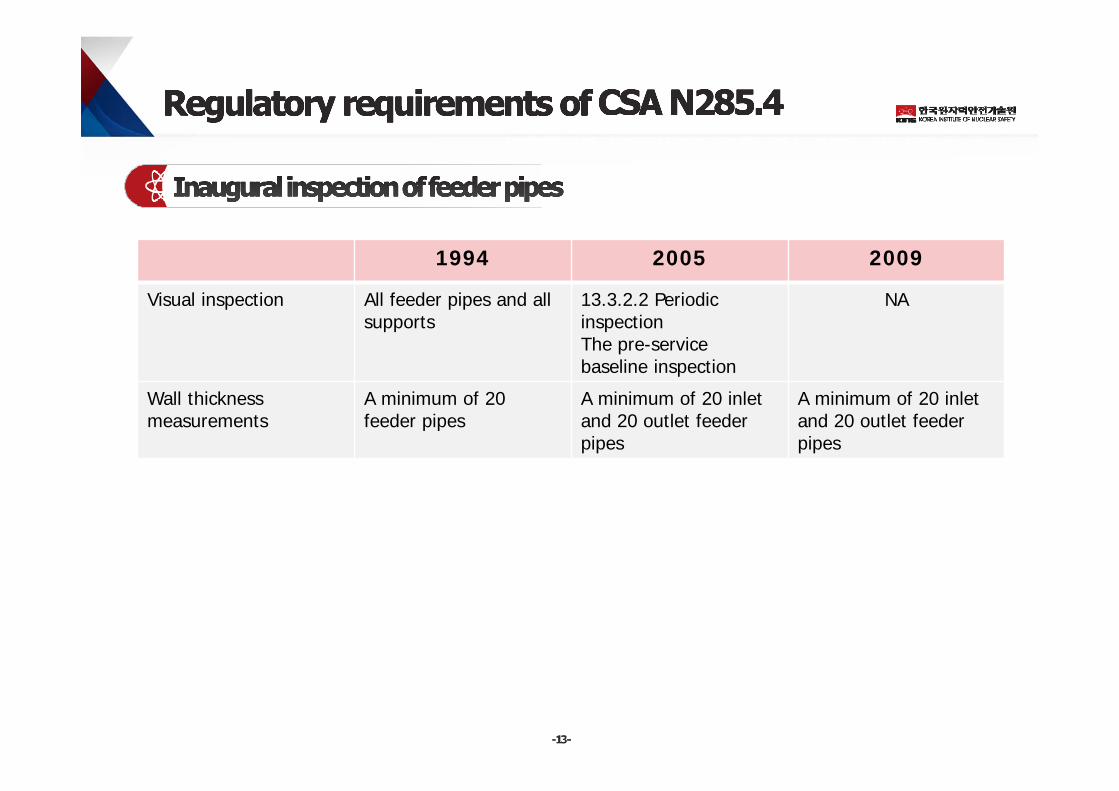
1994 2005 2009
Visual inspection All feeder pipes and all supports
13.3.2.2 Periodic inspectionThe pre-service baseline inspection
NA
Wall thickness measurements
A minimum of 20 feeder pipes
A minimum of 20 inlet and 20 outlet feeder pipes
A minimum of 20 inlet and 20 outlet feeder pipes
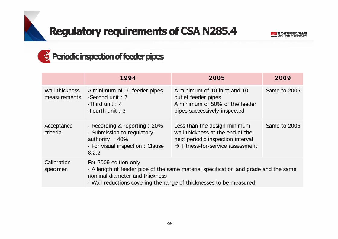
1994 2005 2009
Wall thickness measurements
A minimum of 10 feeder pipes -Second unit : 7-Third unit : 4-Fourth unit : 3
A minimum of 10 inlet and 10 outlet feeder pipesA minimum of 50% of the feeder pipes successively inspected
Same to 2005
Acceptance criteria
- Recording & reporting : 20%- Submission to regulatory authority : 40% - For visual inspection : Clause 8.2.2
Less than the design minimum wall thickness at the end of the next periodic inspection interval Fitness-for-service assessment
Same to 2005
Calibration specimen
For 2009 edition only- A length of feeder pipe of the same material specification and grade and the same nominal diameter and thickness- Wall reductions covering the range of thicknesses to be measured
13.4 Volumetric inspection of feeder piping of CSA N285.4(2014)
As a minimum, the assessment report on feeder cracking potential shall be reviewed by the licensee at least once every 6 years to confirm continued report validity or to determine that the report requires an update. The review shall be documented and the regulatory authority shall be notified of the review findings. The inspection intervals defined in Clause 13.2.3.1 may be used to define intervals for review of the feeder cracking potential assessment report.
Note: As the feeder cracking potential assessment report can be used to limit volumetric inspection of feeder piping, it is considered good practice to review the validity of the assessment interval on a regular basis to include new operational experience and changes in conditions affecting cracking potential.
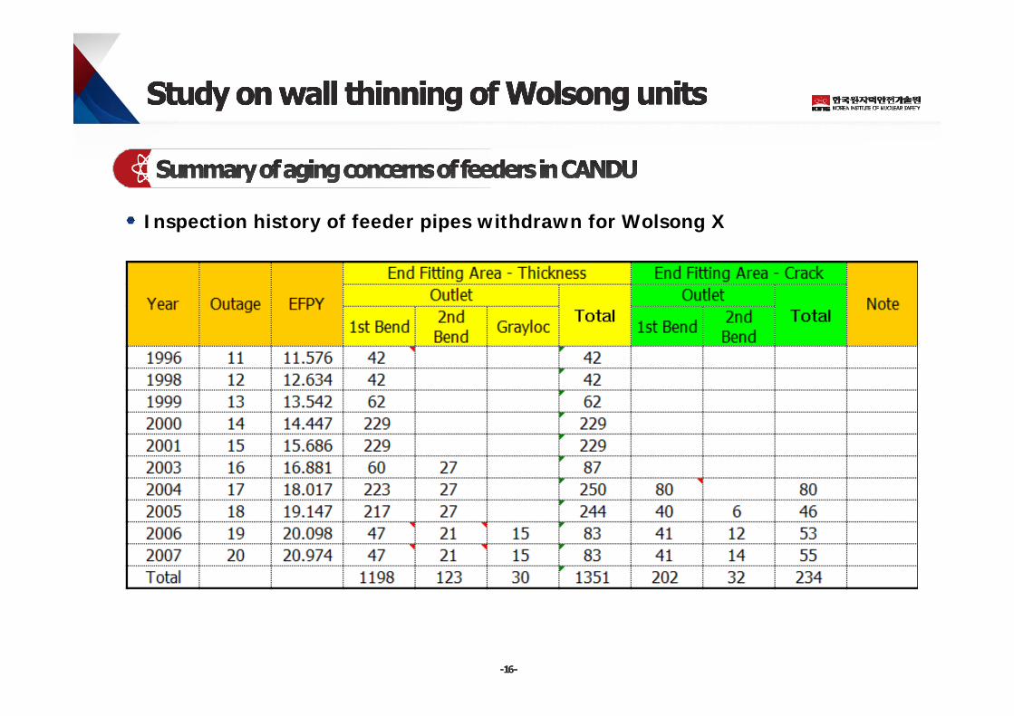
Inspection history of feeder pipes withdrawn for Wolsong X
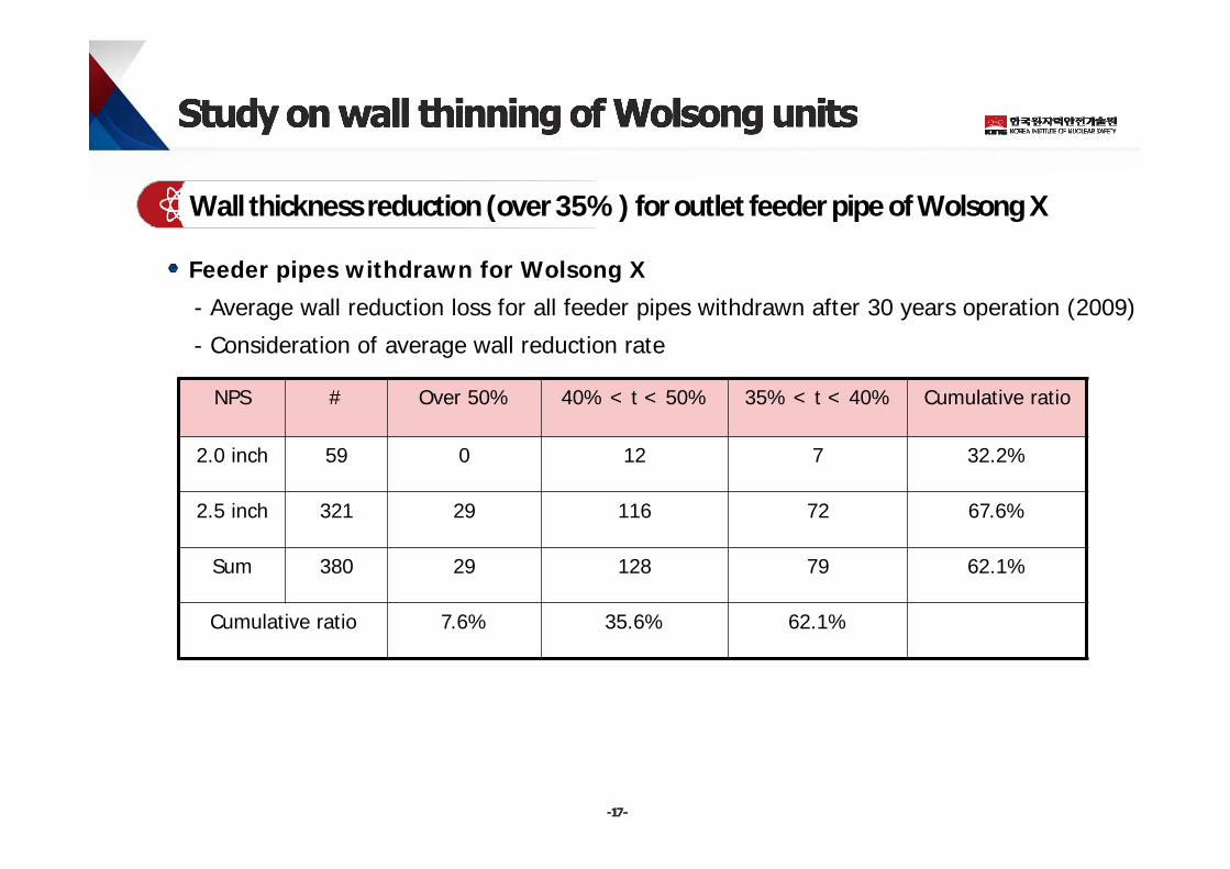
Wall thickness reduction (over 35%) for outlet feeder pipe of Wolsong X
NPS # Over 50% 40% < t < 50% 35% < t < 40% Cumulative ratio
2.0 inch 59 0 12 7 32.2%
2.5 inch 321 29 116 72 67.6%
Sum 380 29 128 79 62.1%
Cumulative ratio 7.6% 35.6% 62.1%
Feeder pipes withdrawn for Wolsong X
- Average wall reduction loss for all feeder pipes withdrawn after 30 years operation (2009)
- Consideration of average wall reduction rate
For feeder pipes of Wolsong Xs
- Increase of average chromium content : 0.02 0.036 ~ 0.051
For refurnished feeder pipes of Wolsong X
- Material specification change : SA 106 Gr. B SA 106 Gr. C
- A minimum chromium content was increased rather than that of Woslong Xs
- Increase of nominal wall thickness for 2” feeder pipes : 5.537mm 6.350mm
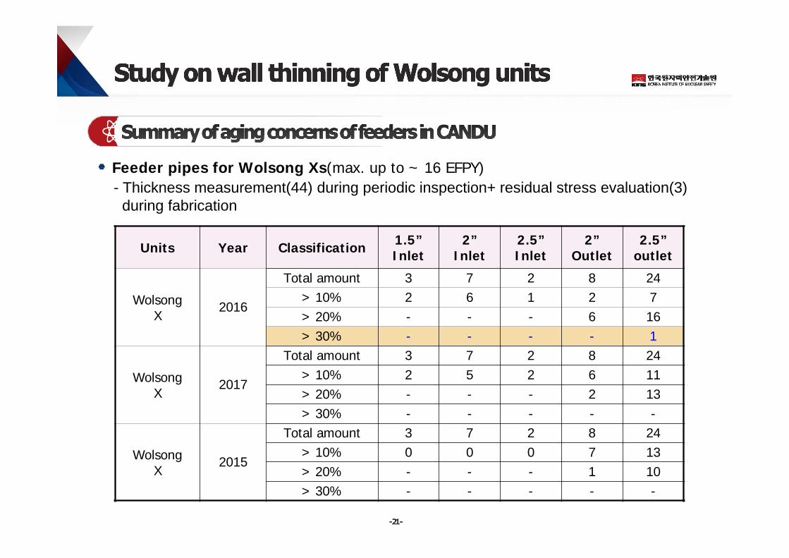
Feeder pipes for Wolsong Xs(max. up to ~ 16 EFPY)- Thickness measurement(44) during periodic inspection+ residual stress evaluation(3)
during fabrication
Units Year Classification 1.5” Inlet
2” Inlet
2.5”Inlet
2”Outlet
2.5”outlet
Wolsong X
2016
Total amount 3 7 2 8 24> 10% 2 6 1 2 7> 20% - - - 6 16> 30% - - - - 1
Wolsong X
2017
Total amount 3 7 2 8 24> 10% 2 5 2 6 11> 20% - - - 2 13> 30% - - - - -
Wolsong X
2015
Total amount 3 7 2 8 24> 10% 0 0 0 7 13> 20% - - - 1 10> 30% - - - - -
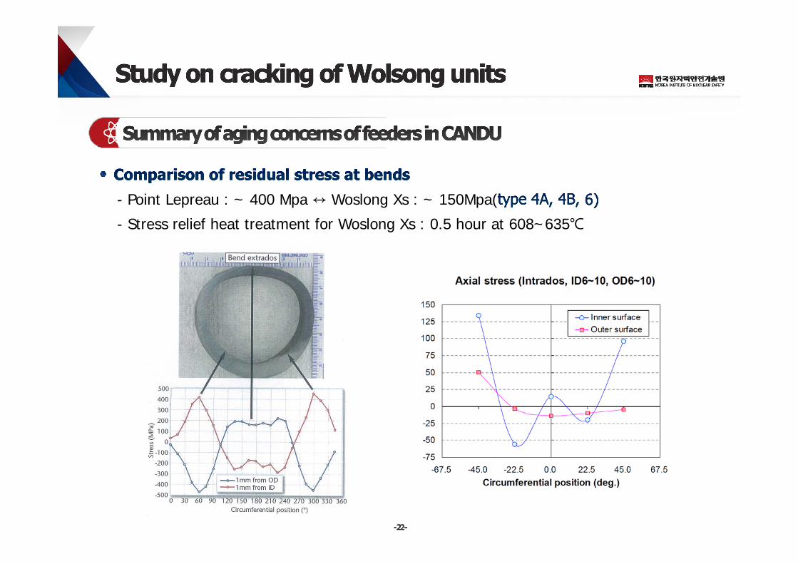
- Point Lepreau : ~ 400 Mpa ↔ Woslong Xs : ~ 150Mpa(
- Stress relief heat treatment for Woslong Xs : 0.5 hour at 608~635℃
- High potential micro cracks during cold worked bending process
- Relatively low residual stress at bends for feeders during manufacturing stage and
tempering heat treatment
- Low potential cracking at gralyoc welds, fluid device DWs, and swage welds
- UT for feeders subject to wall thinning over 30% of Wolsong X as a lead plant
- Lesson to be learned from micro examinations of previous removed feeders subject to
wall thinning over 55% for Wolsong X
- Assessment on feeder cracking potential every 6 years in accordance with CSA 285.4
(2014)
▣ Short-term planRe-establishment of operating velocity(v.s. design velocity) and chromium content for each feeder
Selection and measurement of weakness point due to wall thinining through survey of CFD results(shear stress), mechanical properties change by heat treatment of residual stress relief, limit load distribution of cold worked(bend angle) and wall thinned bend.
Application of conventional UT for a feeder subject to wall thinning over 30% of Wolsong X as a lead plant
Determination of the rate of change over the last interval for at least 50% of the minimum inspection sample size
Proceduralization of wall thinning rate evaluation & no cracking defects, residual lifetime determination and acceptance criteria for feeder pipes
▣ Long-term planPreparation and review of assessment report on feeder cracking potential at least once every 6 years
Evaluation of feeder cracking potential for first bend + second bend, grayloc welding, flow device DWM(Dissimilar weld metal), orifice welding, etc. in parallel with CANADA feeders LBB(Leak before break)
Introduction of performance demonstration for ultrasonic thickness measurement & volumetric inspection
Submission of feeder pipe life-cycle management program to regulatory body in accordance with regulatory document 2.6.3 & CSA 285.4
Submission of fitness for service assessment to regulatory body in accordance with FFSG(Feeder fitness for service Guidelines) and CSA 285.4