functional cell carriers for tissue engineering - publikationsserver
TRANSCRIPT
Michael Hacker
Functional Cell Carriersfor Tissue Engineering
Fabrication & Characterization
FunctionalFunctional CellCell CarriersCarriersforfor Tissue EngineeringTissue Engineering
FabricationFabrication & & CharacterizationCharacterization
Dissertation zur Erlangung des Doktorgrades der Naturwissenschaften (Dr. rer. nat.) der Fakultät Chemie und Pharmazie der Universität Regensburg

Functional Cell Carriers for Tissue Engineering
Fabrication & Characterization
Dissertation zur Erlangung des Doktorgrades der Naturwissenschaften (Dr. rer. nat.)
der Fakultät Chemie und Pharmazie der Universität Regensburg
vorgelegt von Michael Hacker
aus Erlangen im August 2004
Diese Doktorarbeit entstand in der Zeit von März 2000 bis August 2004 am Lehrstuhl
für Pharmazeutische Technologie an der Universität Regensburg.
Die Arbeit wurde von Prof. Dr. Achim Göpferich angeleitet.
Promotionsgesuch eingereicht am: 13. August 2004
Mündliche Prüfung am: 2. September 2004
Prüfungsausschuss: Prof. Dr. S. Elz (Vorsitzender)
Prof. Dr. A. Göpferich (Erstgutachter)
Univ.-Prof. Dr. M.B. Schulz (Zweitgutachter)
Prof. Dr. A. Kurtz (Drittprüfer)

Meiner Familie in Liebe und Dankbarkeit gewidmet.
Im Andenken an Ernst Hacker.

Fabrication of Functional Cell Carriers
- 5 -
Table of Contents
Chapter 1 Introduction and Goals of the Thesis......................................................... 7
Chapter 2 Mediating Specific Cell Adhesion to Low-adhesive Diblock Copolymers
by Instant Modification with RGD-peptides ........................................... 41
Chapter 3 Towards Biomimetic Scaffolds: Anhydrous Scaffold Fabrication from
Biodegradable Amine-reactive Diblock Copolymers ............................. 59
Chapter 4 Hansen Solubility Parameters as a Means to Replace Halogenated
Solvents in Biomaterial Processing ......................................................... 93
Chapter 5 Solubility Parameters of Poly(lactic acid) and its Copolymers -
Theoretical and Experimental Considerations....................................... 117
Chapter 6 Solid Lipid Templating: A Versatile Lab-scale Fabrication Technique for
Macroporous Tissue Engineering Scaffolds.......................................... 141
Chapter 7 Synthesis and Characterization of Injectable, Thermogelling
Poly(N-isopropylacrylamide)-grafted Gelatin (PNiPAAm-gelatin)...... 167
Chapter 8 Summary and Conclusions .................................................................... 191
Appendix Abbreviations ........................................................................................ 203
Hansen Solubility Parameters of common solvents .............................. 206
Solubility Parameter Map...................................................................... 209
Program Listing ..................................................................................... 210
Curriculum vitae.................................................................................... 217
List of Publications................................................................................ 218
Acknowledgements ............................................................................... 223


Fabrication of Functional Cell Carriers
Chapter 1
Introduction and
Goals of the Thesis

Chapter 1 Introduction and Goals of the Thesis
- 9 -
1. Tissue Engineering
At the end of the year 2002, 82,749 patients were registered on the OPTN (Organ
Procurement and Transplantation Network) waiting list for organ transplantation (from the
OPTN / SRTR Annual report on www.optn.org) with kidney (68%) and liver (22%) being the
most required organs followed by lung (5%) and heart (5%). In contrast, a total of only
24,544 organs could be transplanted. Further data provided by the OPTN indicates a death
rate of approximately 10% on the waiting list. The active waiting list of Eurotransplant states
the need for 12,157 kidneys and 1,841 livers as of July 1, 2004 (from www.eurotransplant.nl).
Not only is the need for organs constantly rising, less complex tissues, such as skin, are also
required to more efficiently cure the 4.5 million severe burn injuries that are reported each
year (from www.medindic.net). Due to the constantly rising life expectancy, the discrepancy
between organ donations and patients on the waiting list will become even worse. In the
United States, for example, an estimated one person in five reaching 65 years of age will
receive temporary or permanent organ-replacement therapy during their remaining life span
[1].
These few examples drastically indicate why the replacement of organ functions and living
tissue with synthetic substitutes represents one of the most important contributions of 20th
century science to clinical medicine [1]. Organ failure and tissue defects resulting from
traumatic injury, tumor resection, degenerative deceases, and congenital deformities are the
specific problem surgeons have to face with [2-4]. Current strategies to deal with complex
tissue defects and organ failure involve surgical reconstruction and organ transplantation.
Besides the organ shortage, the risk associated with long-term treatments with
immunosuppressive medication is a critical shortcoming in transplantation medicine. Existing
methods of tissue replacement therapy rely upon a variety of permanent implants made of
metals, ceramics, non-degradable polymers, or composite materials [5-7]. Most of these
devices were developed in the 1960s and gradually optimized throughout the following
decades. However, such implant devices can only restore tissue form and mechanical
function, while their application is limited by finite durability and non-physiological
performance as well as a considerable risk of infection or thromboembolism [8]. Surgical
tissue reconstruction by the transplantation of autografts, however, is still the ‘gold standard’
in the management of several tissue defects, especially osseous defects. Nevertheless, this
Chapter 1 Introduction and Goals of the Thesis
- 10 -
treatment is often constrained by anatomical limitations and associated with donor-site pain
and morbidity, extra blood loss and risk of infection [9].
To overcome these limitations, tissue engineering emerged as discovery research in the 1970s
[10]. The National Science Foundation (NSF) defined tissue engineering as an
interdisciplinary field that applies the principles of engineering and the life sciences to the
development of biological substitutes that restore, maintain, or improve tissue function [2].
Work in the field is focused towards replacing tissue defects with living tissue that is ideally
generated from autologous cells and designed to meet the specific needs of each individual
patient [8]. Generally, two different strategies have been adopted for the de novo generation
of living tissue from isolated cells. One involves the in vitro cultivation of the harvested cells
on three-dimensional cell carriers under tailored conditions and biological stimuli. Following
this strategy, the cell carrier, which is fabricated from a biomaterial, provides the
macroporous architecture on which cells can attach, proliferate and develop into the desired
tissue, thus assuming the function of the natural extracellular matrix [11]. The other strategy
favors the direct in vivo implantation of isolated cells with and without an artificial matrix [2].
Ideally, both strategies lead to a tissue construct that is ultimately indistinguishable from the
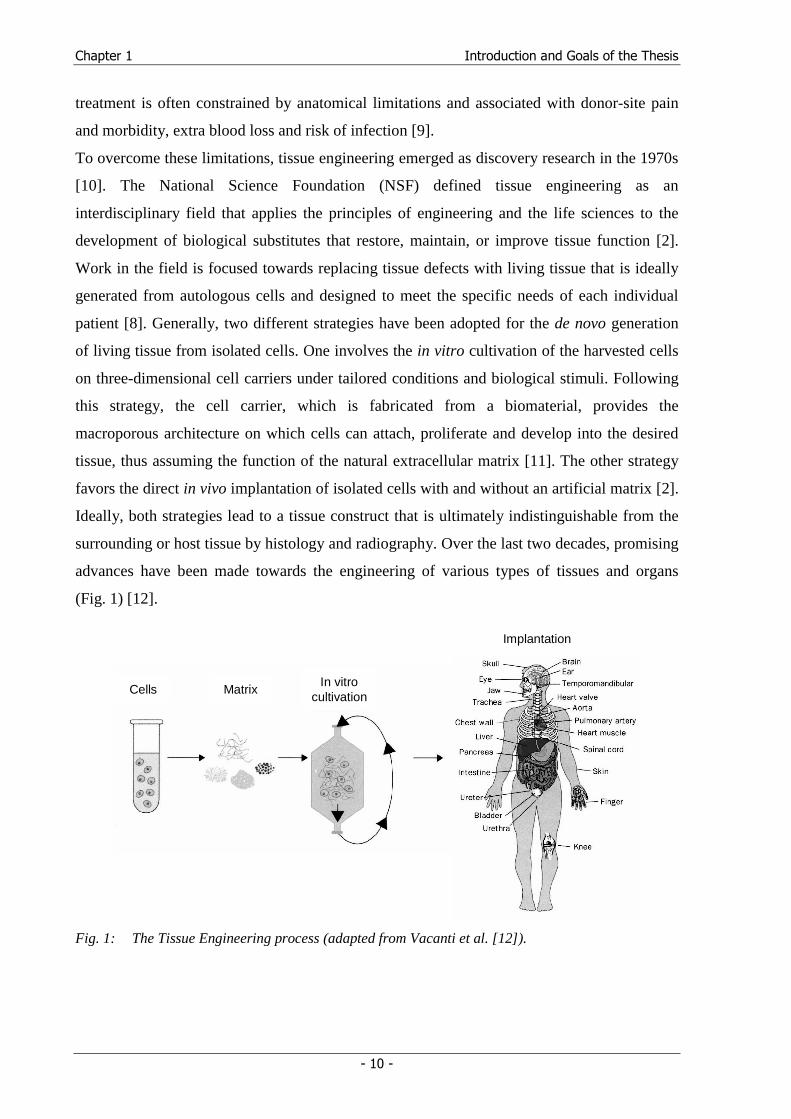
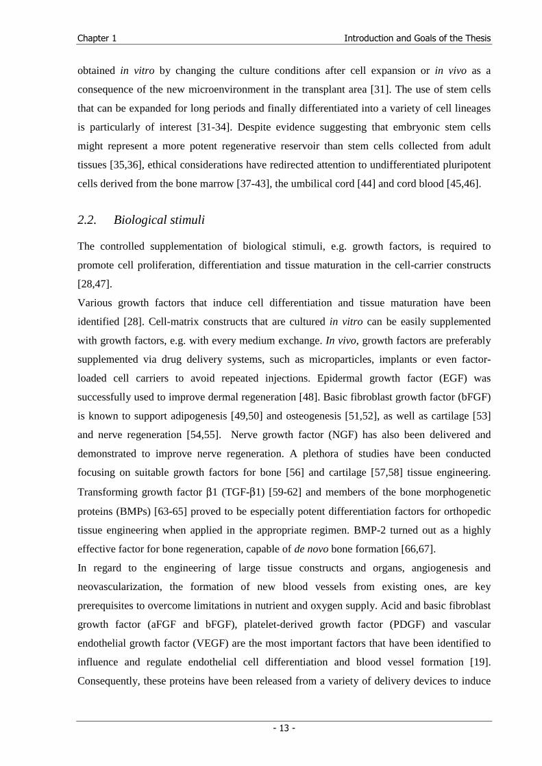
surrounding or host tissue by histology and radiography. Over the last two decades, promising
advances have been made towards the engineering of various types of tissues and organs
(Fig. 1) [12].
Cells Matrix In vitro
cultivation
Implantation
Fig. 1: The Tissue Engineering process (adapted from Vacanti et al. [12]).
Chapter 1 Introduction and Goals of the Thesis
- 11 -
By the end of 2002, twenty tissue-engineered products had entered Food and Drug
Administration clinical trials, while four were already approved: Apligraf® (Organogenesis;
living skin), Carticel® (Genzyme Biosurgery; autologous chondrocytes), Dermagraft® (ATS;
living skin), and OrCel® (Ortec; living skin) [13]. Germany's BioTissue Technologies AG
has five products in clinical use since the end of 2001 (www.biotissue-tec.com). BioTissue
follows the principle of autologous (patient's own) tissue replacement to treat skin
(BioSeed®-S), oral mucosa (BioSeed®-M), oral bone (BioSeed®-Oral Bone) and cartilage
(BioSeed®-C) defects. The specific cells are taken from the patient as a tissue specimen
(biopsy) and then cultured in a GMP-certified laboratory. Once the required quantity of newly
cultured cells is reached, combining the cells with a specific, resorbable biomatrix enables the
cells to be transplanted into the existing defect.
Generally, the total U.S. health care costs for patients suffering from tissue loss or organ
failure exceed $400 billion per year and approximately 8 million surgical procedures are
performed annually to treat these disorders. It has been estimated that the total market for
tissue-engineered products is $80 billion annually in the United States alone [10]. Despite this
tremendous economic potential, the field has yet to produce a profitable product [13].
However, the transition from a development state to a successful product has been constrained
both by regulatory issues [14-16] and the complexity of tissue biology [17] . Critical issues in
creating an entire organ or even a complex functional tissue include enhancing cell survival,
maintaining the differentiated function, developing a significant cell mass embedded in its
extracellular matrix, and achieving vascularization [10]. Future research has especially to
overcome the problems arising from insufficient nutrient supply and the lack of
vascularization [18,19]. Furthermore, cell carriers and scaffolding materials have to be
designed to mimic natural extracellular matrix design and cell-matrix-interactions, and to
support the structural orientation of the developing tissue with regard to the engineering of
entire organs [20-23].
Chapter 1 Introduction and Goals of the Thesis
- 12 -
2. The cell carrier-based Tissue Engineering concept
The most common approach to tissue regeneration is based on cell-matrix constructs (Fig. 1)
[4,24]. This concept is derived from the natural tissue assembly, where cells are embedded in
a tissue-specific extracellular matrix that is composed of structural proteins (collagen and
elastin), specialized proteins supporting cell matrix-interactions (e.g. fibrillin, fibronectin, and
laminin) and hydrophilic proteoglycans (e.g. hyaluronic acis or glycosaminoglycans) [25].
This matrix supports cell proliferation, migration and tissue development [26].
The cell-matrix strategy of tissue engineering generally involves the following components
and steps [27-29]: (i) An appropriate cell source, either allogeneic or autologous, must be
identified, the cells need to be isolated and produced in sufficient numbers. (ii) A suitable
biocompatible material that can be used as a cell substrate (open system) or cell-encapsulation
material (closed system) must be isolated or synthesized and manufactured into the desired
shape and dimensions, forming an artificial extracellular matrix. (iii) The cells must be
uniformly seeded onto or into the material and grown in a bioreactor. (iv) The appropriate
biochemical and/or mechanical stimulus must be identified and administered or applied in a
controlled manner (amount and time) to improve cell differentiation, extracellular matrix
production and tissue formation. (v) Finally, the engineered structure is placed into the in vivo
site, where, depending on the site and the structure, vascularization may be necessary.
2.1. Cell types and sources
Suitable cells for tissue engineering applications generally include autologous cells from the
patient, allogeneic cells from a human donor who is not immunologically identical to the
patient, and xenogeneic cells from a different species [17]. The ideal way to obtain cells is to
harvest autologous cells directly from the patient, followed by controlled expansion in vitro
[30]. Although this option is preferred because the cells are acceptable to the recipient’s
immune system without the need for immunosuppressive therapy, it is limited by the scarcity
of available donor tissue and donor site morbidity. Each category, autologous, allogeneic, or
xenogeneic, may be further delineated in terms of whether the cells are differentiated (mature
cells) or undifferentiated (progenitor or stem cells). In most cases, differentiated cells isolated
from adult tissues exhibit a very limited proliferative capacity and tend to lose differentiation
within the first passages. Culturing progenitor or stem cells that, by definition, have a higher
proliferative capacity is more promising.The differentiation of such cells, however, has to be
Chapter 1 Introduction and Goals of the Thesis
- 13 -
obtained in vitro by changing the culture conditions after cell expansion or in vivo as a
consequence of the new microenvironment in the transplant area [31]. The use of stem cells
that can be expanded for long periods and finally differentiated into a variety of cell lineages
is particularly of interest [31-34]. Despite evidence suggesting that embryonic stem cells
might represent a more potent regenerative reservoir than stem cells collected from adult
tissues [35,36], ethical considerations have redirected attention to undifferentiated pluripotent
cells derived from the bone marrow [37-43], the umbilical cord [44] and cord blood [45,46].
2.2. Biological stimuli
The controlled supplementation of biological stimuli, e.g. growth factors, is required to
promote cell proliferation, differentiation and tissue maturation in the cell-carrier constructs
[28,47].
Various growth factors that induce cell differentiation and tissue maturation have been
identified [28]. Cell-matrix constructs that are cultured in vitro can be easily supplemented
with growth factors, e.g. with every medium exchange. In vivo, growth factors are preferably
supplemented via drug delivery systems, such as microparticles, implants or even factor-
loaded cell carriers to avoid repeated injections. Epidermal growth factor (EGF) was
successfully used to improve dermal regeneration [48]. Basic fibroblast growth factor (bFGF)
is known to support adipogenesis [49,50] and osteogenesis [51,52], as well as cartilage [53]
and nerve regeneration [54,55]. Nerve growth factor (NGF) has also been delivered and
demonstrated to improve nerve regeneration. A plethora of studies have been conducted
focusing on suitable growth factors for bone [56] and cartilage [57,58] tissue engineering.
Transforming growth factor β1 (TGF-β1) [59-62] and members of the bone morphogenetic
proteins (BMPs) [63-65] proved to be especially potent differentiation factors for orthopedic
tissue engineering when applied in the appropriate regimen. BMP-2 turned out as a highly
effective factor for bone regeneration, capable of de novo bone formation [66,67].
In regard to the engineering of large tissue constructs and organs, angiogenesis and
neovascularization, the formation of new blood vessels from existing ones, are key
prerequisites to overcome limitations in nutrient and oxygen supply. Acid and basic fibroblast
growth factor (aFGF and bFGF), platelet-derived growth factor (PDGF) and vascular
endothelial growth factor (VEGF) are the most important factors that have been identified to
influence and regulate endothelial cell differentiation and blood vessel formation [19].
Consequently, these proteins have been released from a variety of delivery devices to induce
Chapter 1 Introduction and Goals of the Thesis
- 14 -
angiogenesis in engineered tissue constructs [19,68-70]. It was demonstrated that the dual
delivery of VEGF-165 and PDGF, each with distinct kinetics, from a single, structural
polymer scaffold results in the rapid formation of a mature vascular network [71]. Another
study demonstrated that VEGF-121 remained an active and very efficient mitogen for human
endothelial cells after immobilization to fibrin. The fibrin-VEGF hydrogels are proposed as a
growth matrix for ischemic regions that require an angiogenic response [72]. Recently, a
hydrogel system was designed that is capable for the on-demand release of matrix-conjugated
VEGF [73].
2.3. Cell carrier (scaffold)
In cell carrier-based tissue engineering attempts, the macroporous three-dimensional cell
carriers (scaffolds) play a pivotal role in cell seeding, proliferation, and new tissue formation
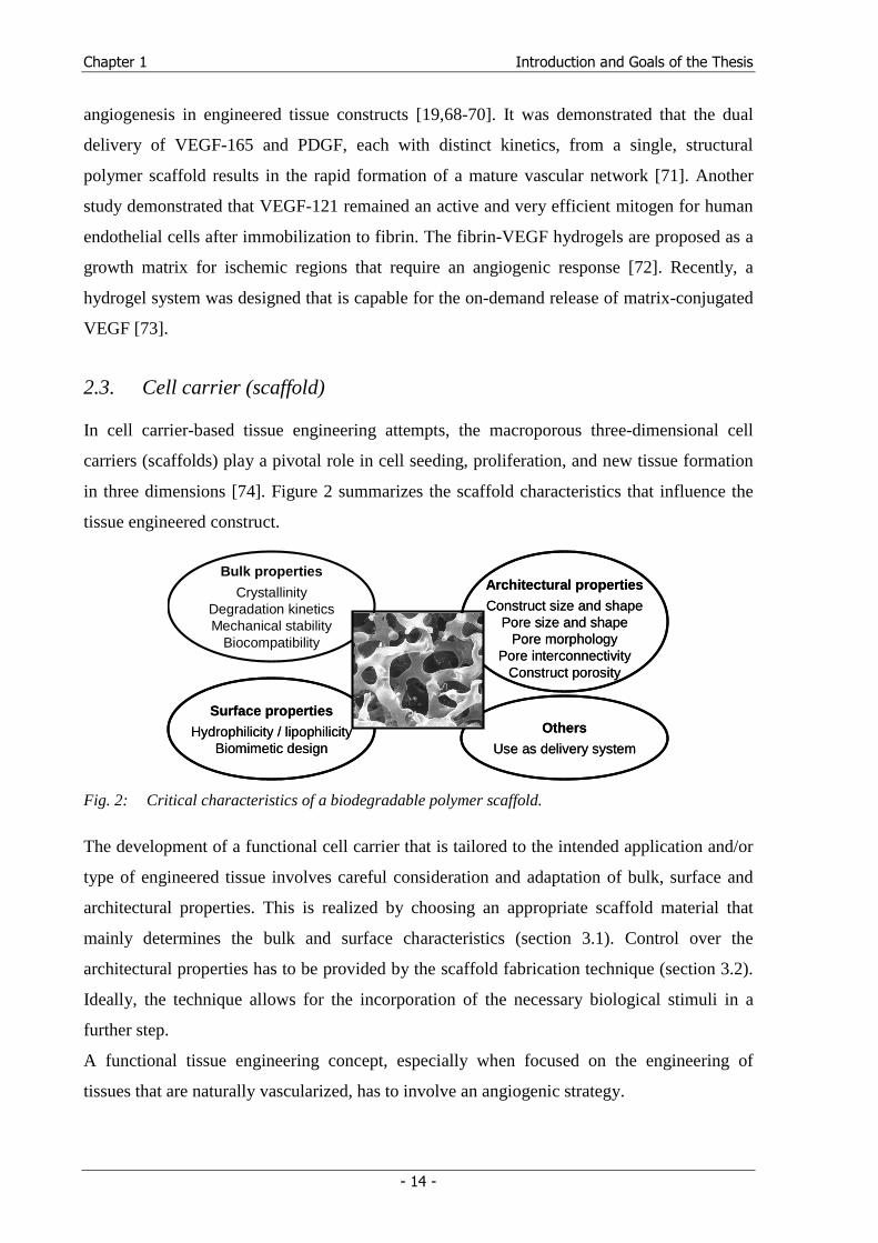
in three dimensions [74]. Figure 2 summarizes the scaffold characteristics that influence the
tissue engineered construct.
Bulk properties
CrystallinityDegradation kineticsMechanical stability
Biocompatibility
Surface properties
Hydrophilicity / lipophilicityBiomimetic design
Surface properties
Hydrophilicity / lipophilicityBiomimetic design
Architectural properties
Construct size and shapePore size and shape
Pore morphologyPore interconnectivity
Construct porosity
Architectural properties
Construct size and shapePore size and shape
Pore morphologyPore interconnectivity
Construct porosity
Others
Use as delivery system
Others
Use as delivery system
Fig. 2: Critical characteristics of a biodegradable polymer scaffold.
The development of a functional cell carrier that is tailored to the intended application and/or
type of engineered tissue involves careful consideration and adaptation of bulk, surface and
architectural properties. This is realized by choosing an appropriate scaffold material that
mainly determines the bulk and surface characteristics (section 3.1). Control over the
architectural properties has to be provided by the scaffold fabrication technique (section 3.2).
Ideally, the technique allows for the incorporation of the necessary biological stimuli in a
further step.
A functional tissue engineering concept, especially when focused on the engineering of
tissues that are naturally vascularized, has to involve an angiogenic strategy.
Chapter 1 Introduction and Goals of the Thesis
- 15 -
3. Scaffold materials and fabrication techniques
3.1. Biomaterials for Tissue Engineering
A large variety of biomaterials, namely natural and synthetic polymers, ceramics and metals
have been employed as scaffold materials [40,75-82]. On the basis of the materials
hydrophilicity and mechanical properties, the scaffolding materials can be divided into
materials that swell significantly in water forming a hydrogel and materials that only dissolve
in organic solvents and are used for the fabrication of macroporous solids. Due to the
mechanical properties, hydrogels are the preferred materials for the engineering of soft
tissues, nerve fibers and blood vessels [73,83-86]. For the engineering of skeletal tissue,
especially bone, the appropriate scaffolds should maintain a rigid structure under
physiological conditions.
Hydrogel forming materials
Hydrogels have been increasingly studied as matrices for tissue engineering due to their
mechanical similarity to the natural extracellular matrix [75]. Hydrogels are characterized by
a high water content and pores that can accommodate living cells. Table 1 gives a survey of
the wide and diverse range of hydrogel-forming polymers that are used in biomedical
applications. The substances can be categorized into natural polymer hydrogels, synthetic
polymer hydrogels and combinations of the two classes. Natural materials, such as collagen,
which is a key component of the extracellular matrix, and gelatin, which is denatured
collagen, are of special interest as these polymers interact with cells and induce tissue
formation [11,87]. While collagen forms gels in physiological environments (pH and
temperature), gelatin dissolves in water at body temperature. Therefore, chemical crosslinking
with glutaraldehyde, genipin or other crosslinkers is often used to render gelatin insoluble
[88-90]. Hydrogel matrices, prepared from crosslinked gelatin, have been comprehensively
investigated by Tabata and co-workers in a variety of tissue engineering studies [50,52,61,91].
In these studies, the hydrogel serves not only as cell carrier but also as a growth factor
delivery system. Combinations of gelatin with other natural materials, such as alginate or
hyaluronic acid, are accepted materials for skin reconstruction [92,93]. Mooney and
coworkers have intensively investigated the feasibility of ionically crosslinked alginate
hydrogels as cell carriers for tissue engineering experiments [84,94,95].
Chapter 1 Introduction and Goals of the Thesis
- 16 -
Table 1: Hydrophilic polymers used to synthesize hydrogel matrices (adapted from [75])
Natural polymers and their derivatives (± crosslinkers) Anionic polymers: hyaluronic acid, alginate, pectin, carrageenan, chondroitin sulfate, dextran sulfate Cationic polymers: chitosan, polylysine Amphipathic polymers: collagen, gelatin, carboxymethyl chitin, fibrin Neutral polymers: dextran, agarose, pullulan
Synthetic polymers (± crosslinkers) Polyesters: PEG-PLA-PEG, PEG-PLGA-PEG, PEG-PCL-PEG, PLA-PEG-PLA, PHB, poly(PF-co-EG) ± acrylate end groups
Other polymers PEG-bis-(PLA-acrylate), PEG-CDs, PEG-g-poly(AAm-co-vinyl amine), poly(AAm), poly(NiPAAm-co-AAc), poly(NiPAAm-co-EMA), PVAc/PVA, PNVP, poly(MMA-co-HEMA), poly(AN-co-allyl sulfonate), poly(biscarboxy-phenoxy-phosphazene), poly(GEMA-sulfate)
Combinations of natural and synthetic polymers P(PEG-co-peptides), alginate-g-(PEO-PPO-PEO), P(PLGA-co-serine), collagen-acrylate, alginate-acrylate, poly(HPMA-g-peptide), poly(HEMA/ Matrigel®), hyaluronic acid-g-NiPAAm Abbreviations: CD, cyclodextrin; EG, ethylene glycol; HEMA, hydroxyethyl methacrylate; AAc, acrylic acid; AAm, acrylamide; AN, acrylonitrile; EMA, ethyl methacrylate; GEMA, glucosylethyl methacrylate; HEMA, hydroxyethyl methacrylate; HPMA, hydroxypropyl methacrylamide; MMA, methyl methacrylate; NiPAAm, N-isopropyl acrylamide; PCL, poly(caprolactone); PEG, poly(ethylene glycol); PEO, poly(ethylene oxide); PF, propylene fumarate; PHB, poly(hydroxy butyrate); PLA, poly(lactic acid); PLGA, poly(lactic-co-glycolic acid); PNVP, poly(N-vinyl pyrrolidone); PPO, poly(propylene oxide); PVA, poly(vinyl alcohol); PVAc, poly(vinyl acetate)
Many different routes have been used to form hydrogels from the polymers listed in Table 1.
Gelation is induced either physically or chemically [75]. Physical gels are formed by a change
of temperature (e.g. poly(NiPAAm), PEO-PPO-PEO)) or pH (e.g. polyAAc, collagen), by
mixing polyanions and polycations (e.g. alginate-chitosan), or by crosslinking a
polyelectrolyte with multivalent ions (e.g. calcium-alginate). Chemical gels are synthesized
by a crosslinking reaction between electron-poor olefins, such as acrylate, vinyl or fumarate
groups. In this way a plethora of PEG- or PEO-based hydrogels has been synthesized [96-98].
Recent research has particularly been focused on injectable hydrogel systems, which are
liquid at room temperature to enable a comfortable mixing with cells and/or growth factors
and form a gel when heated up to body temperature. Promising examples are poly(NiPAAm)-
based copolymers exhibiting thermoreversible gelation properties [99-101] and in situ
polymerizable PEG-based macromers [96,98,102,103]. For instance, injectable PEG-fumarate
based hydrogels, like oligo(poly(ethylene glycol)-fumarate) (OPF) and poly(PF-co-EG), have
been demonstrated to be biocompatible, biodegradable and suitable biomaterials for the
engineering of bone-like tissue [104-109].
Different strategies have been applied to further improve these hydrophilic hydrogels with
regard to tissue engineering applications. By covalently attaching adhesion peptides
containing the tripeptide Arg-Gly-Asp (RGD), artificial extracellular matrix substitutes have
Chapter 1 Introduction and Goals of the Thesis
- 17 -
been developed [22,110-112]. Hubbel and coworkers introduced a fully-synthetic substitute of
alginate for cell encapsulation [113] and developed an injectable PEG-based hydrogel for
bone regeneration that is proteolytically remodeled by ingrown cells and delivers BMP-2
[114].
The ease with which one may covalently incorporate cell adhesion peptides and the potential
to design injectable systems are two significant advantages of using hydrogels as tissue
engineering matrices vs. more hydrophobic alternatives. However, a major disadvantage of
hydrogels is their low mechanical strength, which poses a significant challenge in their
handling. Sterilization issues are also very challenging [75]. A further parameter to consider is
the biodegradability of the material. Polyacrylate hydrogels, many polysaccharides, alginates,
and polyethers (PEG, PEO, PPO), for example, do not degrade in a physiological
environment, but can be excreted if the molecular weight is below the renal threshold barrier
[115,116].
Generally, hydrogels containing cell adhesive components are biodegradable and can be
remodeled by encapsulated or invading cells, forming a practical and useful material for
biomedical applications that do not require a mechanical stable carrier. We intend to employ a
functional hydrogel that delivers angiogenetic growth factors and can be injected into rigid
scaffolds as an ingrowth matrix for blood vessels.
Materials for the fabrication of rigid scaffolds
Tissue engineering scaffolds have been fabricated from natural and synthetic polymers,
ceramics and metals [40,79,117,118]. Biodegradable polymers are the most attractive and
widely applied scaffolding materials, often considered superior to ceramics and metals
because they degrade as the new tissues are formed [79,119]. In contrast to natural scaffolding
materials, such as collagen, chitosan or chitin, these synthetic polymers can be supplied in
reproducible quality and free of pathogenic or immunogenic organic residues.
Poly(α-hydroxy acids), namely poly(D,L-lactic acid) (PLA) and copolymers (PLGA) with
poly(glycolic acid) (PGA), a polymer that has already been approved by the FDA as a suture
material, are probably the most common class of synthetic, biodegradable polymers. Further
materials that are under investigation are polyanhydrides [120], polycaprolactones [121] and
copolymers with PLA [122], polycarbonates [123], polyurethans [124] and polyfumarates
[125]. The polymer structures are summarized in Table 2.
Chapter 1 Introduction and Goals of the Thesis
- 18 -
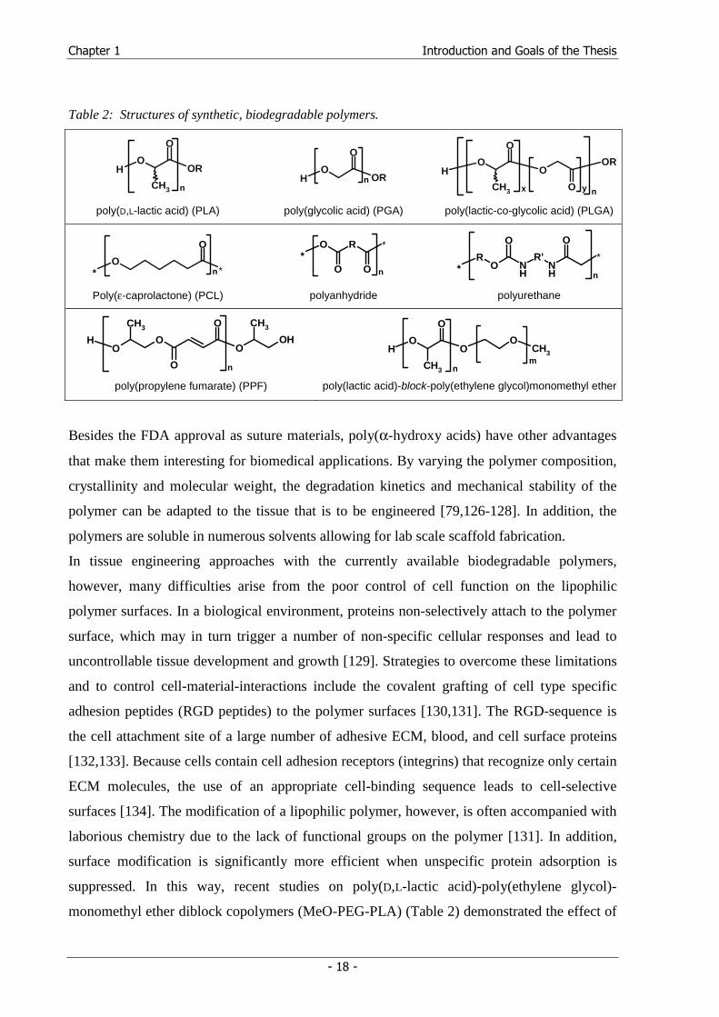
Table 2: Structures of synthetic, biodegradable polymers.
HO
O
CH3
OR
n
HO
O
ORn
HO
O
CH3
O
O
OR
x
n
y
poly(D,L-lactic acid) (PLA) poly(glycolic acid) (PGA) poly(lactic-co-glycolic acid) (PLGA)
*O
n
*
O
*O R
n
*
O O
*R
On
NH
R'NH
OO
*
Poly(ε-caprolactone) (PCL) polyanhydride polyurethane
OO
OOH
O
OCH3 CH3
H
n
CH3HO
O
O
O
CH3 n
m
poly(propylene fumarate) (PPF) poly(lactic acid)-block-poly(ethylene glycol)monomethyl ether
Besides the FDA approval as suture materials, poly(α-hydroxy acids) have other advantages
that make them interesting for biomedical applications. By varying the polymer composition,
crystallinity and molecular weight, the degradation kinetics and mechanical stability of the
polymer can be adapted to the tissue that is to be engineered [79,126-128]. In addition, the
polymers are soluble in numerous solvents allowing for lab scale scaffold fabrication.
In tissue engineering approaches with the currently available biodegradable polymers,
however, many difficulties arise from the poor control of cell function on the lipophilic
polymer surfaces. In a biological environment, proteins non-selectively attach to the polymer
surface, which may in turn trigger a number of non-specific cellular responses and lead to
uncontrollable tissue development and growth [129]. Strategies to overcome these limitations
and to control cell-material-interactions include the covalent grafting of cell type specific
adhesion peptides (RGD peptides) to the polymer surfaces [130,131]. The RGD-sequence is
the cell attachment site of a large number of adhesive ECM, blood, and cell surface proteins
[132,133]. Because cells contain cell adhesion receptors (integrins) that recognize only certain
ECM molecules, the use of an appropriate cell-binding sequence leads to cell-selective
surfaces [134]. The modification of a lipophilic polymer, however, is often accompanied with
laborious chemistry due to the lack of functional groups on the polymer [131]. In addition,
surface modification is significantly more efficient when unspecific protein adsorption is
suppressed. In this way, recent studies on poly(D,L-lactic acid)-poly(ethylene glycol)-
monomethyl ether diblock copolymers (MeO-PEG-PLA) (Table 2) demonstrated the effect of
Chapter 1 Introduction and Goals of the Thesis
- 19 -
reduced protein adsorption, caused by the presence of the hydrophilic poly(ethylene glycol)
(PEG) [135,136]. The altered surface chemistry also had a significant effect on cell adhesion
and cell differentiation compared to unmodified PLA [137]. With the objective of enabling a
convenient surface modification with adhesion peptides or growth factors to create a
biomimetic surface design, a new class of amine- and thiol-reactive polymers was developed
on basis of the PEG-PLA diblock copolymers [138,139]. These reactive copolymers are
designed to covalently bind peptides or proteins from aqueous solutions to preformed polymer
surfaces during a simple incubation step. As the positive effects of surface-attached adhesion
peptides on cell adhesion are thoroughly described [131], the first studies indicate that
covalently attached growth factors retained their activity and activated their receptors and
downstream signaling proteins [140-142]. Non-diffusional growth factors may allow for
localized cell stimulation, surface patterning and a prolonged half-life of the protein. A
surface modification concept based on reactive diblock copolymers would allow for an “off
the shelf” scaffold or implant coating fabrication, which could be covalently modified with
peptides in response to individual needs by incubation with a sterile solution of the required
peptide. The general feasibility of this concept has been previously shown in a study on the
immobilization of fluorescent dyes or model proteins to preformed films [139]. These
polymers are therefore promising scaffold materials for the fabrication of functional or even
biomimetic scaffolds.
Chapter 1 Introduction and Goals of the Thesis
- 20 -
4. Scaffold fabrication techniques
Several requirements have to be considered in the design of macroporous, polymeric scaffolds
for tissue engineering [74,143,144]. First, the scaffold material should be biocompatible and
biodegradable. Second, an ideal scaffold is highly porous with an interconnected pore
network to accommodate cells, to support cell proliferation and differentiation, and to
enhance tissue formation. A high porosity (> 90%) is also important for sufficient oxygen
supply and to guarantee unimpaired flow transport of nutrients and metabolic wastes. Third, a
suitable surface chemistry is necessary to optimize cell attachment, proliferation, and
differentiation. Fourth, the scaffold should have adequate mechanical properties to match
those of the tissues at the site of implantation.
A variety of processing technologies have been developed to fabricate polymeric scaffolds.
These techniques mainly include textile technologies, solvent casting and particulate leaching,
gas foaming, emulsion freeze drying, thermally induced phase separation, electrospinning,
and rapid prototyping.
Fiber meshes / fiber bonding
Fibers, produced by textile technology, have been used to fabricate non-woven meshes from
PGA and PLLA [24] (Fig. 3a). Fiber meshes represent the ‘gold standard’ in permeability and
are still the standard scaffolds for many applications, but lack the necessary structural
stability. To improve the mechanical properties of the meshes, the PGA fibers were bound
together with solutions of other polymers [145]. In detail, PLLA is dissolved in methylene
chloride, which is not a solvent for PLA, and cast over the PGA mesh. After solvent
evaporation, the construct is heated above the melting point of PGA. Finally, the PLLA is
removed by dissolving in methylene chloride again. This treatment results in a mesh of PGA
fibers joined at the cross-points.
Electrospinning
Electrospinning is a fabrication process that uses an electric field to control the formation and
deposition of polymer fibers onto a target substrate [146-149]. The electrospinning technique
can fabricate fibrous scaffolds from polymer solutions or melts with fiber diameters ranging
from several microns down to several hundred nanometers [146] (Fig. 3b).
Chapter 1 Introduction and Goals of the Thesis
- 21 -
i)i)g)g) h)h)
f)f)f)d)d) e)e)
a)a) b)b) cc
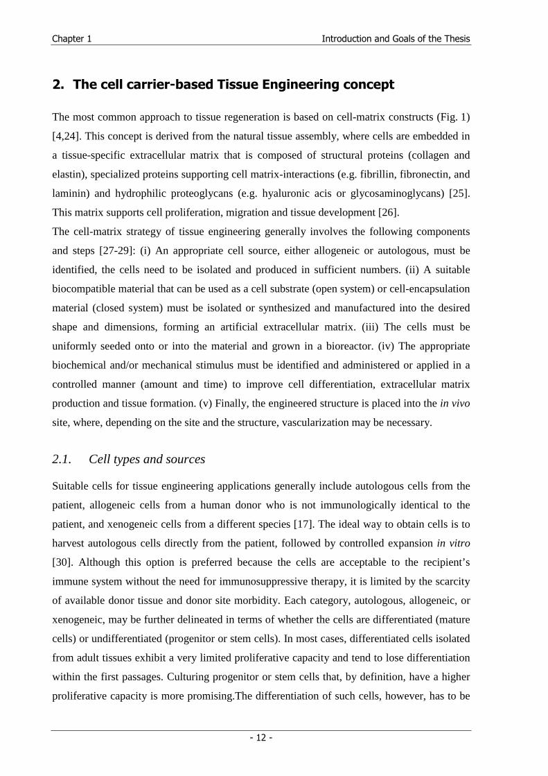
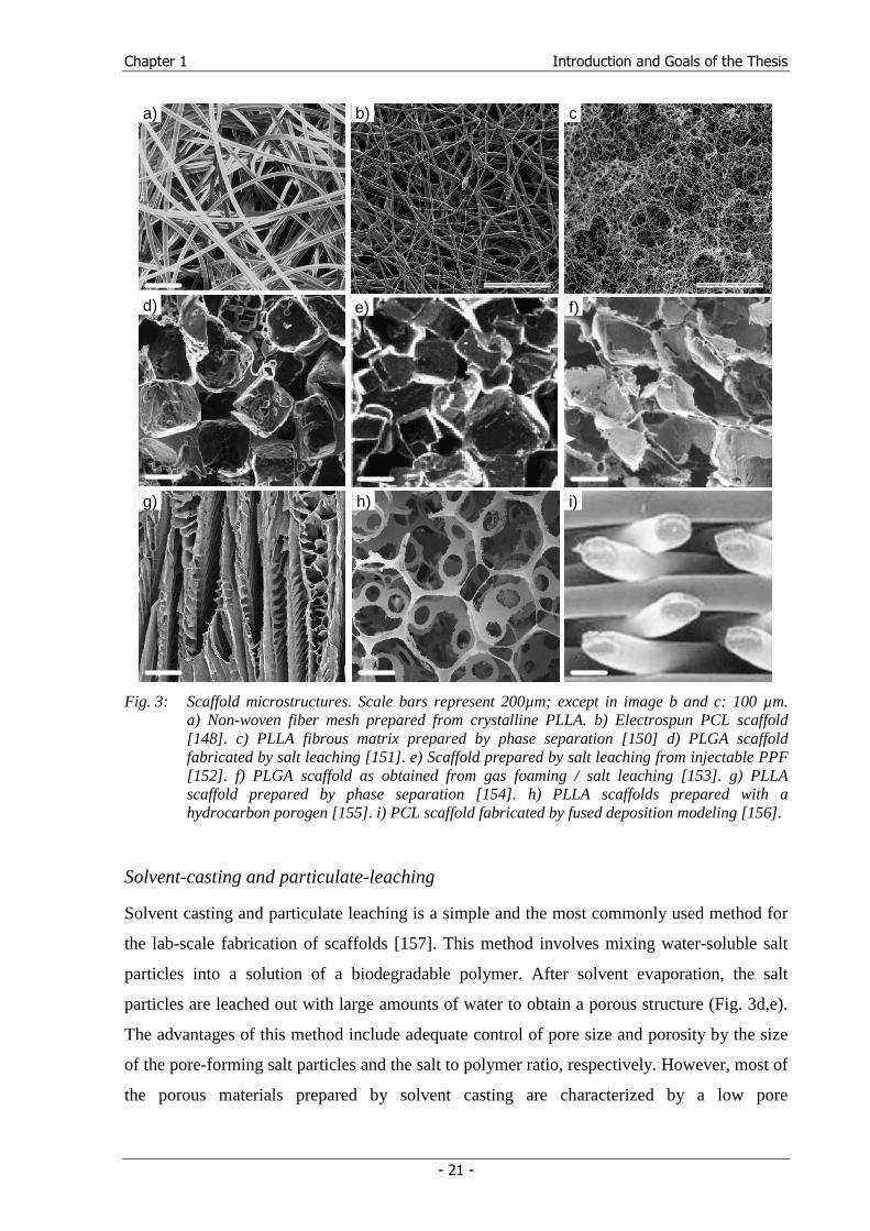
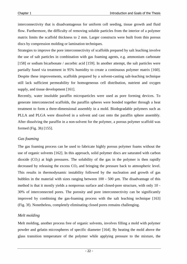
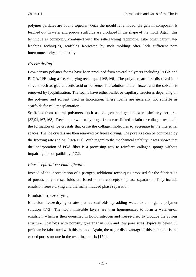
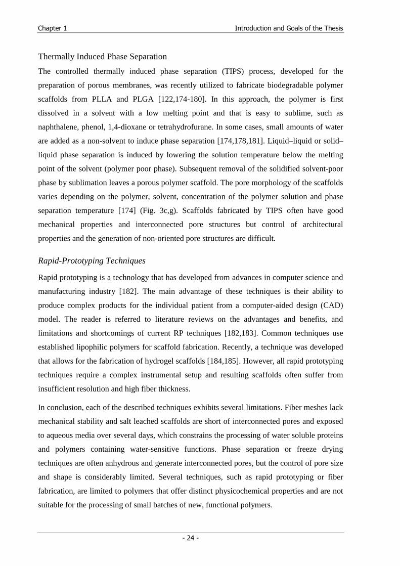
Fig. 3: Scaffold microstructures. Scale bars represent 200µm; except in image b and c: 100 µm.
a) Non-woven fiber mesh prepared from crystalline PLLA. b) Electrospun PCL scaffold [148]. c) PLLA fibrous matrix prepared by phase separation [150] d) PLGA scaffold fabricated by salt leaching [151]. e) Scaffold prepared by salt leaching from injectable PPF [152]. f) PLGA scaffold as obtained from gas foaming / salt leaching [153]. g) PLLA scaffold prepared by phase separation [154]. h) PLLA scaffolds prepared with a hydrocarbon porogen [155]. i) PCL scaffold fabricated by fused deposition modeling [156].
Solvent-casting and particulate-leaching
Solvent casting and particulate leaching is a simple and the most commonly used method for
the lab-scale fabrication of scaffolds [157]. This method involves mixing water-soluble salt
particles into a solution of a biodegradable polymer. After solvent evaporation, the salt
particles are leached out with large amounts of water to obtain a porous structure (Fig. 3d,e).
The advantages of this method include adequate control of pore size and porosity by the size
of the pore-forming salt particles and the salt to polymer ratio, respectively. However, most of
the porous materials prepared by solvent casting are characterized by a low pore
Chapter 1 Introduction and Goals of the Thesis
- 22 -
interconnectivity that is disadvantageous for uniform cell seeding, tissue growth and fluid
flow. Furthermore, the difficulty of removing soluble particles from the interior of a polymer
matrix limits the scaffold thickness to 2 mm. Larger constructs were built from thin porous
discs by compression molding or lamination techniques.
Strategies to improve the pore interconnectivity of scaffolds prepared by salt leaching involve
the use of salt particles in combination with gas foaming agents, e.g. ammonium carbonate
[158] or sodium bicarbonate / ascorbic acid [159]. In another attempt, the salt particles were
partially fused via treatment in 95% humidity to create a continuous polymer matrix [160].
Despite these improvements, scaffolds prepared by a solvent-casting salt-leaching technique
still lack sufficient permeability for homogeneous cell distribution, nutrient and oxygen
supply, and tissue development [161].
Recently, water insoluble paraffin microparticles were used as pore forming devices. To
generate interconnected scaffolds, the paraffin spheres were bonded together through a heat
treatment to form a three-dimensional assembly in a mold. Biodegradable polymers such as
PLLA and PLGA were dissolved in a solvent and cast onto the paraffin sphere assembly.
After dissolving the paraffin in a non-solvent for the polymer, a porous polymer scaffold was
formed (Fig. 3h) [155].
Gas foaming
The gas foaming process can be used to fabricate highly porous polymer foams without the
use of organic solvents [162]. In this approach, solid polymer discs are saturated with carbon
dioxide (CO2) at high pressures. The solubility of the gas in the polymer is then rapidly
decreased by releasing the excess CO2 and bringing the pressure back to atmospheric level.
This results in thermodynamic instability followed by the nucleation and growth of gas
bubbles in the material with sizes ranging between 100 - 500 µm. The disadvantage of this
method is that it mostly yields a nonporous surface and closed-pore structure, with only 10 -
30% of interconnected pores. The porosity and pore interconnectivity can be significantly
improved by combining the gas-foaming process with the salt leaching technique [163]
(Fig. 3f). Nonetheless, completely eliminating closed pores remains challenging.
Melt molding
Melt molding, another process free of organic solvents, involves filling a mold with polymer
powder and gelatin microspheres of specific diameter [164]. By heating the mold above the
glass transition temperature of the polymer while applying pressure to the mixture, the
Chapter 1 Introduction and Goals of the Thesis
- 23 -
polymer particles are bound together. Once the mould is removed, the gelatin component is
leached out in water and porous scaffolds are produced in the shape of the mold. Again, this
technique is commonly combined with the salt-leaching technique. Like other particulate-
leaching techniques, scaffolds fabricated by melt molding often lack sufficient pore
interconnectivity and porosity.
Freeze drying
Low-density polymer foams have been produced from several polymers including PLGA and
PLGA/PPF using a freeze-drying technique [165,166]. The polymers are first dissolved in a
solvent such as glacial acetic acid or benzene. The solution is then frozen and the solvent is
removed by lyophilization. The foams have either leaflet or capillary structures depending on
the polymer and solvent used in fabrication. These foams are generally not suitable as
scaffolds for cell transplantation.
Scaffolds from natural polymers, such as collagen and gelatin, were similarly prepared
[82,91,167,168]. Freezing a swollen hydrogel from crosslinked gelatin or collagen results in
the formation of ice crystals that cause the collagen molecules to aggregate in the interstitial
spaces. The ice crystals are then removed by freeze-drying. The pore size can be controlled by
the freezing rate and pH [169-171]. With regard to the mechanical stability, it was shown that
the incorporation of PGA fiber is a promising way to reinforce collagen sponge without
impairing biocompatibility [172].
Phase separation / emulsification
Instead of the incorporation of a porogen, additional techniques proposed for the fabrication
of porous polymer scaffolds are based on the concepts of phase separation. They include
emulsion freeze-drying and thermally induced phase separation.
Emulsion freeze-drying
Emulsion freeze-drying creates porous scaffolds by adding water to an organic polymer
solution [173]. The two immiscible layers are then homogenized to form a water-in-oil
emulsion, which is then quenched in liquid nitrogen and freeze-dried to produce the porous
structure. Scaffolds with porosity greater than 90% and low pore sizes (typically below 50
µm) can be fabricated with this method. Again, the major disadvantage of this technique is the
closed pore structure in the resulting matrix [174].
Chapter 1 Introduction and Goals of the Thesis
- 24 -
Thermally Induced Phase Separation
The controlled thermally induced phase separation (TIPS) process, developed for the
preparation of porous membranes, was recently utilized to fabricate biodegradable polymer
scaffolds from PLLA and PLGA [122,174-180]. In this approach, the polymer is first
dissolved in a solvent with a low melting point and that is easy to sublime, such as
naphthalene, phenol, 1,4-dioxane or tetrahydrofurane. In some cases, small amounts of water
are added as a non-solvent to induce phase separation [174,178,181]. Liquid–liquid or solid–
liquid phase separation is induced by lowering the solution temperature below the melting
point of the solvent (polymer poor phase). Subsequent removal of the solidified solvent-poor
phase by sublimation leaves a porous polymer scaffold. The pore morphology of the scaffolds
varies depending on the polymer, solvent, concentration of the polymer solution and phase
separation temperature [174] (Fig. 3c,g). Scaffolds fabricated by TIPS often have good
mechanical properties and interconnected pore structures but control of architectural
properties and the generation of non-oriented pore structures are difficult.
Rapid-Prototyping Techniques
Rapid prototyping is a technology that has developed from advances in computer science and
manufacturing industry [182]. The main advantage of these techniques is their ability to
produce complex products for the individual patient from a computer-aided design (CAD)
model. The reader is referred to literature reviews on the advantages and benefits, and
limitations and shortcomings of current RP techniques [182,183]. Common techniques use
established lipophilic polymers for scaffold fabrication. Recently, a technique was developed
that allows for the fabrication of hydrogel scaffolds [184,185]. However, all rapid prototyping
techniques require a complex instrumental setup and resulting scaffolds often suffer from
insufficient resolution and high fiber thickness.
In conclusion, each of the described techniques exhibits several limitations. Fiber meshes lack
mechanical stability and salt leached scaffolds are short of interconnected pores and exposed
to aqueous media over several days, which constrains the processing of water soluble proteins
and polymers containing water-sensitive functions. Phase separation or freeze drying
techniques are often anhydrous and generate interconnected pores, but the control of pore size
and shape is considerably limited. Several techniques, such as rapid prototyping or fiber
fabrication, are limited to polymers that offer distinct physicochemical properties and are not
suitable for the processing of small batches of new, functional polymers.
Chapter 1 Introduction and Goals of the Thesis
- 25 -
5. Goals of the Thesis
A functional cell carrier design concept involves a biodegradable material that allows for a
tailored interaction with cells in terms of adhesion and differentiation. Furthermore, a suitable
scaffold fabrication technique is required to process lab-scale amounts of the polymer into
macroporous, biocompatible and biodegradable cell carriers with controlled architectural
properties. Last but not least, a concept to induce neovascularization of the tissue engineered
construct has to be established.
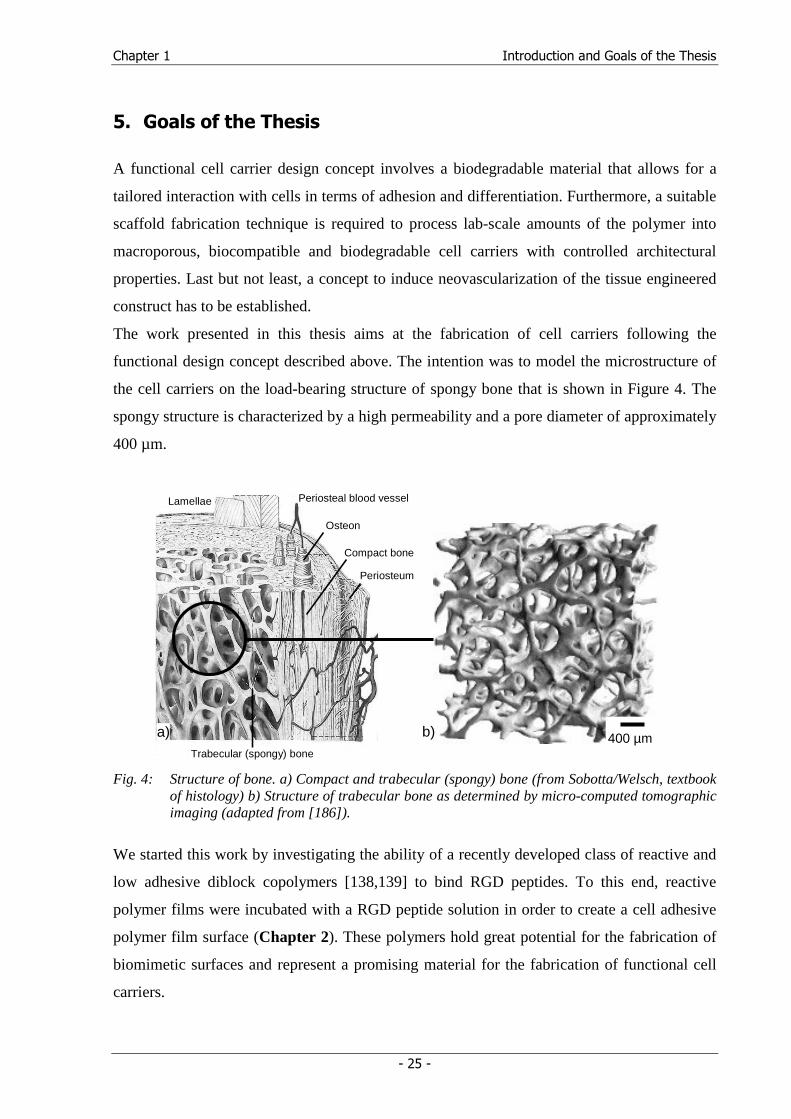
The work presented in this thesis aims at the fabrication of cell carriers following the
functional design concept described above. The intention was to model the microstructure of
the cell carriers on the load-bearing structure of spongy bone that is shown in Figure 4. The
spongy structure is characterized by a high permeability and a pore diameter of approximately
400 µm.
Lamellae
Osteon
Trabecular (spongy) bone
Compact bone
Periosteal blood vessel
Periosteum
Fig. 4: Structure of bone. a) Compact and trabecular (spongy) bone (from Sobotta/Welsch, textbook of histology) b) Structure of trabecular bone as determined by micro-computed tomographic imaging (adapted from [186]).
We started this work by investigating the ability of a recently developed class of reactive and
low adhesive diblock copolymers [138,139] to bind RGD peptides. To this end, reactive
polymer films were incubated with a RGD peptide solution in order to create a cell adhesive
polymer film surface (Chapter 2). These polymers hold great potential for the fabrication of
biomimetic surfaces and represent a promising material for the fabrication of functional cell
carriers.
400 µm b) a)
Chapter 1 Introduction and Goals of the Thesis
- 26 -
Chapter 3 aims at the processing of amine-reactive diblock copolymers into macroporous
cell carriers with a spongy microstructure. To this end, a technique was developed (solid lipid
templating) on the basis of an anhydrous processing concept [187] that employs triglycerides
as biocompatible porogen materials and a non-halogenated solvent mixture to process the
block copolymers into appropriate cell carriers. The technique combines the advantages of a
particulate leaching technique, namely control of pore size, pore shape, and scaffold porosity,
with a phase separation concept to obtain a highly interconnected pore structure. Insulin was
used as a model protein that was bound to the surface of a prefabricated surface to
demonstrate the preservation of polymer reactivity during processing.
Typical solvents for the processing of biodegradable polymers are chloroform and methylene
chloride. In the development stages of the solid lipid templating technique, an azeotropic
mixture from acetone and chloroform was employed and suitable processing parameters that
result in the desired scaffold microstructure were established. In order to replace the
halogenated solvent mixture with a less toxic (according to the ICH guideline on residual
solvents [188]) solvent or solvent mixture without the need for the laborious adaptation of
processing parameters, we followed a thermodynamic approach. The Hansen solubility
parameters (HSPs) of the established solvent mixture were determined and a
thermodynamically similar solvent or solvent mixture was systematically searched by
solubility parameter comparison (Chapter 4).
Based on the promising results of the solvent replacement study, which indicated the
usefulness of the HSPs as predictive parameters in polymer processing, we aimed at the
determination of the HSPs of poly(lactic acid), poly(lactic-co-glycolic acid) and monomethyl
ether-poly(ethylene glycol)-block-poly(lactic acid) using theoretical and experimental
methods (Chapter 5).
Since the architectural properties of a scaffold influence fluid flow and tissue development
within the scaffold, the processing parameters to vary these architectural parameters are
determined in a further study (Chapter 6). To this end, rheological measurements are
conducted to access the required adaptation of polymer concentration to varied porogen
particle properties. In addition, several polymers characterized by different molecular weights
and compositions are processed using the solid lipid templating technique to demonstrate the
versatility of this lab-scale process.
Finally, an injectable hydrogel matrix was developed from gelatin and PNiPAAm (Chapter
7). The conjugate contains gelatin, which is denatured collagen, a key component of the
natural ECM, to attract blood vessel ingrowth. Due to the gelatin backbone, the hydrogel can
Chapter 1 Introduction and Goals of the Thesis
- 27 -
be proteolytically remodeled by ingrown cells, because the peptide is a substrate for matrix
metalloproteinases. Since gelatin dissolves in aqueous media under physiological conditions,
PNiPAAm chains are grafted to the peptide to trigger gelation at body temperature.
Rheological measurements are performed to demonstrate and characterize the thermogelling
of the conjugate. Cell culture experiments are performed to access cell viability in the gels.
This hydrogel is the first step towards an ingrowth matrix to support neovascularization of
tissue engineered constructs. To this end, angiogenetic growth factors will be incorporated in
the hydrogel in future studies.
Chapter 1 Introduction and Goals of the Thesis
- 28 -
6. References
(1) Lysaght MJ, Nguy NA, Sullivan K. 'An economic survey of the emerging tissue engineering industry'. Tissue Eng (1998); 4: 231-238.
(2) Langer R, Vacanti JP. 'Tissue engineering'. Science (1993); 260: 920-926.
(3) Bruder SP, Fox BS. 'Tissue engineering of bone. Cell based strategies'. Clin Orthop (1999); S68-S83.
(4) Freed LE, Vunjak-Novakovic G. 'Culture of organized cell communities'. Adv Drug Delivery Rev (1998); 33: 15-30.
(5) Spector M. 'Historical review of porous-coated implants'. J Arthroplasty (1987); 2: 163-177.
(6) Pilliar RM. 'Porous-surfaced metallic implants for orthopedic applications'. J Biomed Mater Res (1987); 21: 1-33.
(7) Simon JP, Fabry G. 'An overview of implant materials'. Acta Orthop Belg (1991); 57: 1-5.
(8) Fuchs JR, Nasseri BA, Vacanti JP. 'Tissue engineering: a 21st century solution to surgical reconstruction'. Ann Thorac Surg (2001); 72: 577-591.
(9) Kenley RA, Yim K, Abrams J, Ron E, Turek T, Marden LJ, Hollinger JO. 'Biotechnology and bone graft substitutes'. Pharm Res (1993); 10: 1393-1401.
(10) Langer R. 'Tissue Engineering'. Mol Ther (2000); 1: 12-15.
(11) Kleinman HK, Philp D, Hoffman MP. 'Role of the extracellular matrix in morphogenesis'. Curr Opin Biotechnol (2003); 14: 526-532.
(12) Vacanti JP, Langer R. 'Tissue engineering: the design and fabrication of living replacement devices for surgical reconstruction and transplantation'. Lancet (1999); 354: SI32-SI34.
(13) Lysaght MJ, Hazlehurst AL. 'Tissue engineering: the end of the beginning'. Tissue Eng (2004); 10: 309-320.
(14) Indech B. 'The international harmonization of human tissue regulation: Regulatory control over human tissue use and tissue banking in select countries and the current state of international harmonization efforts'. Food Drug Law J (2000); 55: 343-372.
(15) Ward SM. 'Global harmonization of regulatory requirements for premarket approval of autologous cell therapies'. Food Drug Law J (2000); 55: 225-243.
(16) Lloyd-Evans M. 'Regulating tissue engineering'. Mater Today (2004); 7: 48-55.
(17) Griffith LG, Naughton G. 'Tissue engineering - Current challenges and expanding opportunities'. Science (2002); 295: 1009-1014.
Chapter 1 Introduction and Goals of the Thesis
- 29 -
(18) Nomi M, Atala A, Coppi PD, Soker S. 'Principals of neovascularization for tissue engineering'. Mol Aspects Med (2002); 23: 463-483.
(19) Bouhadir KH, Mooney DJ. 'Promoting angiogenesis in engineered tissues'. J Drug Targeting (2001); 9: 397-406.
(20) Hubbell JA. 'Biomaterials in tissue engineering'. Biotechnology (N Y ) (1995); 13: 565-576.
(21) de Groot K, Wen HB, Liu Y, Layrolle P, Barrere F. 'Biomimetic coatings on orthopedic implants: a review'. Mat Res Soc Proc (2000); 599: 109-116.
(22) Shin H, Jo S, Mikos AG. 'Biomimetic materials for tissue engineering'. Biomaterials (2003); 24: 4353-4364.
(23) Drotleff S, Lungwitz U, Breunig M, Dennis A, Blunk T, Tessmar J, Gopferich A. 'Biomimetic polymers in pharmaceutical and biomedical sciences'. Eur J Pharm Biopharm (2004); 58: 385-407.
(24) Cima LG, Vacanti JP, Vacanti C, Ingber D, Mooney D, Langer R. 'Tissue engineering by cell transplantation using degradable polymer substrates'. J Biomed Eng (1991); 113: 143-151.
(25) Bosman FT, Stamenkovic I. 'Functional structure and composition of the extracellular matrix'. J Pathol (2003); 200: 423-428.
(26) Lukashev ME, Werb Z. 'ECM signalling: orchestrating cell behaviour and misbehaviour'. Trends Cell Biol (1998); 8: 437-441.
(27) Langer R, Folkman J. 'Polymers for the sustained release of proteins and other macromolecules'. Nature (1976); 263: 797-800.
(28) Tabata Y. 'The importance of drug delivery systems in tissue engineering'. Pharm Sci Technol Today (2000); 3: 80-89.
(29) Tabata Y. 'Tissue regeneration based on growth factor release'. Tissue Eng (2003); 9: S5-15.
(30) Heath CA. 'Cells for tissue engineering'. Trends Biotechnol (2000); 18: 17-19.
(31) Cancedda R, Dozin B, Giannoni P, Quarto R. 'Tissue engineering and cell therapy of cartilage and bone'. Matrix Biol (2003); 22: 81-91.
(32) Pittenger MF, Mackay AM, Beck SC, Jaiswal RK, Douglas R, Mosca JD, Moorman MA, Simonetti DW, Craig S, Marshak et a. 'Multilineage potential of adult human mesenchymal stem cells'. Science (1999); 284: 143-147.
(33) Vats A, Tolley NS, Polak JM, Buttery LD. 'Stem cells: sources and applications'. Clin Otolaryngol (2002); 27: 227-232.
Chapter 1 Introduction and Goals of the Thesis
- 30 -
(34) Cancedda R, Bianchi G, Derubeis A, Quarto R. 'Cell therapy for bone disease: a review of current status'. Stem Cells (Miamisburg, OH, United States) (2003); 21: 610-619.
(35) Szilvassy SJ. 'The biology of hematopoietic stem cells'. Arch Med Res (2003); 34: 446-460.
(36) Henningson J, Stanislaus MA, Gewirtz AM. '28. Embryonic and adult stem cell therapy'. J Allergy Clin Immunol (2003); 111: 745-753.
(37) Ishaug SL, Crane GM, Miller MJ, Yasko AW, Yaszemski MJ, Mikos AG. 'Bone formation by three-dimensional stromal osteoblast culture in biodegradable polymer scaffolds'. J Biomed Mater Res (1997); 36: 17-28.
(38) Jensen GS, Drapeau C. 'The use of in situ bone marrow stem cells for the treatment of various degenerative diseases'. Med Hypotheses (2002); 59: 422-428.
(39) Mauney JR, Blumberg J, Pirun M, Volloch V, Vunjak-Novakovic G, Kaplan DL. 'Osteogenic Differentiation of Human Bone Marrow Stromal Cells on Partially Demineralized Bone Scaffolds in Vitro'. Tissue Eng (2004); 10: 81-92.
(40) van den Dolder J, Farber E, Spauwen PHM, Jansen JA. 'Bone tissue reconstruction using titanium fiber mesh combined with rat bone marrow stromal cells'. Biomaterials (2003); 24: 1745-1750.
(41) Kruyt MC, Van Gaalen SM, Oner FC, Verbout AJ, De Bruijn JD, Dhert WJA. 'Bone tissue engineering and spinal fusion: The potential of hybrid constructs by combining osteoprogenitor cells and scaffolds'. Biomaterials (2004); 25: 1463-1473.
(42) Derubeis AR, Cancedda R. 'Bone marrow stromal cells (BMSCs) in bone engineering: limitations and recent advances'. Ann Biomed Eng (2004); 32: 160-165.
(43) Buma P, Ramrattan NN, van Tienen TG, Veth RPH. 'Tissue engineering of the meniscus'. Biomaterials (2004); 25: 1523-1532.
(44) Kadner A, Hoerstrup SP, Tracy J, Breymann C, Maurus Ch, Melnitchouk S, Kadner G, Zund G, Turina M. 'Human umbilical cord cells: a new cell source for cardiovascular tissue engineering'. Ann Thorac Surg (2002); 74: 1422-1428.
(45) Perry TE, Roth SJ. 'Cardiovascular tissue engineering: constructing living tissue cardiac valves and blood vessels using bone marrow, umbilical cord blood, and peripheral blood cells'. J Cardiovasc Nurs (2003); 18: 30-37.
(46) Barker JN, Wagner JE. 'Umbilical-cord blood transplantation for the treatment of cancer'. Nat Rev Cancer (2003); 3: 526-532.
(47) Babensee JE, McIntire LV, Mikos AG. 'Growth factor delivery for tissue engineering'. Pharm Res (2000); 17: 497-504.
(48) Hong SR, Lee SJ, Shim JW, Choi YS, Lee YM, Song KW, Park MH, Nam YS, Lee SI. 'Study on gelatin-containing artificial skin IV: a comparative study on the effect of
Chapter 1 Introduction and Goals of the Thesis
- 31 -
antibiotic and EGF on cell proliferation during epidermal healing'. Biomaterials (2001); 22: 2777-2783.
(49) Kimura Y, Ozeki M, Inamoto T, Tabata Y. 'Adipose tissue engineering based on human preadipocytes combined with gelatin microspheres containing basic fibroblast growth factor'. Biomaterials (2003); 24: 2513-2521.
(50) Tabata Y, Miyao M, Inamoto T, Ishii T, Hirano Y, Yamaoki Y, Ikada Y. 'De novo formation of adipose tissue by controlled release of basic fibroblast growth factor'. Tissue Eng (2000); 6: 279-289.
(51) Yamada K, Tabata Y, Yamamoto K, Miyamoto S, Nagata I, Kikuchi H, Ikada Y. 'Potential efficacy of basic fibroblast growth factor incorporated in biodegradable hydrogels for skull bone regeneration'. J Neurosurg (1997); 86: 871-875.
(52) Tabata Y, Yamada K, Hong L, Miyamoto S, Hashimoto N, Ikada Y. 'Skull bone regeneration in primates in response to basic fibroblast growth factor'. J Neurosurg (1999); 91: 851-856.
(53) Fujisato T, Sajiki T, Liu Q, Ikada Y. 'Effect of basic fibroblast growth factor on cartilage regeneration in chondrocyte-seeded collagen sponge scaffold'. Biomaterials (1996); 17: 155-162.
(54) Aebischer P, Salessiotis AN, Winn SR. 'Basic fibroblast growth factor released from synthetic guidance channels facilitates peripheral nerve regeneration across long nerve gaps'. J Neurosci Res (1989); 23: 282-289.
(55) Sakiyama ES, Hubbell JA. 'Development of fibrin derivatives for controlled release of heparin-binding growth factors'. J Control Release (2000); 65: 389-402.
(56) Schliephake H. 'Bone growth factors in maxillofacial skeletal reconstruction'. International Journal of Oral and Maxillofacial Surgery (2002); 31: 469-484.
(57) Blunk T, Sieminski AL, Gooch KJ, Courter DL, Hollander AP, Nahir AM, Langer R, Vunjak-Novakovic G, Freed LE. 'Differential effects of growth factors on tissue-engineered cartilage'. Tissue Eng (2002); 8: 73-84.
(58) Holland TA, Mikos AG. 'Advances in drug delivery for articular cartilage'. J Control Release (2003); 86: 1-14.
(59) Holland TA, Tessmar JKV, Tabata Y, Mikos AG. 'Transforming growth factor-[beta]1 release from oligo(poly(ethylene glycol) fumarate) hydrogels in conditions that model the cartilage wound healing environment'. J Control Release (2004); 94: 101-114.
(60) Vehof JWM, Fisher JP, Dean D, Van der Waerden J-P, Spauwen PHM, Mikos AG, Jansen JA. 'Bone formation in transforming growth factor .beta.-1-coated porous poly(propylene fumarate) scaffolds'. J Biomed Mater Res (2002); 60: 241-251.
(61) Yamamoto M, Tabata Y, Hong L, Miyamoto S, Hashimoto N, Ikada Y. 'Bone regeneration by transforming growth factor beta1 released from a biodegradable hydrogel'. J Control Release (2000); 64: 133-142.
Chapter 1 Introduction and Goals of the Thesis
- 32 -
(62) Fuchs JR, Hannouche D, Terada S, Vacanti JP, Fauza DO. 'Fetal tracheal augmentation with cartilage engineered from bone marrow-derived mesenchymal progenitor cells'. J Pediatr Surg (2003); 38: 984-987.
(63) Hughes FJ, Collyer J, Stanfield M, Goodman SA. 'The effects of bone morphogenetic protein-2, -4, and -6 on differentiation of rat osteoblast cells in vitro'. Endocrinology (1995); 136: 2671-2677.
(64) Valcourt U, Ronziere MC, Winkler P, Rosen V, Herbage D, Mallein GF. 'Different effects of bone morphogenetic proteins 2, 4, 12, and 13 on the expression of cartilage and bone markers in the MC615 chondrocyte cell line'. Exp Cell Res (1999); 251: 264-274.
(65) Nakashima M, Reddi AH. 'The application of bone morphogenetic proteins to dental tissue engineering'. Nat Biotechnol (2003); 21: 1025-1032.
(66) Geiger M, Li RH, Friess W. 'Collagen sponges for bone regeneration with rhBMP-2'. Adv Drug Delivery Rev (2003); 55: 1613-1629.
(67) Whang K, Tsai DC, Nam EK, Aitken M, Sprague SM, Patel PK, Healy KE. 'Ectopic bone formation via rhBMP-2 delivery from porous bioabsorbable polymer scaffolds'. J Biomed Mater Res (1998); 42: 491-499.
(68) Soker S, Machado M, Atala A. 'Systems for therapeutic angiogenesis in tissue engineering'. World J Urol (2000); 18: 10-18.
(69) Elcin YM, Dixit V, Gitnick G. 'Extensive in vivo angiogenesis following controlled release of human vascular endothelial cell growth factor: implications for tissue engineering and wound healing'. Artif Organs (2001); 25: 558-565.
(70) Lokmic Z, Thompson EW, Morrison WA, Mitchell GM. 'Angiogenesis in Tissue Engineering'. Cardiovasc Pathol (2004); 13: 181-181.
(71) Richardson TP, Peters MC, Ennett AB, Mooney DJ. 'Polymeric system for dual growth factor delivery'. Nat Biotechnol (2001); 19: 1029-1034.
(72) Zisch AH, Schenk U, Schense JC, Sakiyama-Elbert SE, Hubbell JA. 'Covalently conjugated VEGF-fibrin matrices for endothelialization'. J Control Release (2001); 72: 101-113.
(73) Zisch AH, Lutolf MP, Ehrbar M, Raeber GP, Rizzi SC, Davies N, Schmokel H, Bezuidenhout D, Djonov V, Zilla et a. 'Cell-demanded release of VEGF from synthetic, biointeractive cell ingrowth matrices for vascularized tissue growth'. FASEB J (2003); 17: 2260-2262.
(74) Liu X, Ma PX. 'Polymeric scaffolds for bone tissue engineering'. Ann Biomed Eng (2004); 32: 477-486.
(75) Hoffman AS. 'Hydrogels for biomedical applications'. Adv Drug Delivery Rev (2002); 54: 3-12.
Chapter 1 Introduction and Goals of the Thesis
- 33 -
(76) Karp JM, Dalton PD, Shoichet MS. 'Scaffolds for tissue engineering'. MRS Bull (2003); 28: 301-306.
(77) Piskin E. 'Biodegradable polymers as biomaterials'. J Biomater Sci , Polym Ed (1995); 6: 775-795.
(78) Seal BL, Otero TC, Panitch A. 'Polymeric biomaterials for tissue and organ regeneration'. Mat Sci Eng R (2001); 34: 147-230.
(79) Agrawal CM, Ray RB. 'Biodegradable polymeric scaffolds for musculoskeletal tissue engineering'. J Biomed Mater Res (2001); 55: 141-150.
(80) Li SH, de Groot K, Layrolle P. 'Bioceramic scaffold with controlled porous structure for bone tissue engineering'. Key Eng Mater (2002); 218-220: 25-30.
(81) Li JP, Li SH, de Groot K, Layrolle P. 'Preparation and characterization of porous titanium'. Key Eng Mater (2002); 218-220: 51-54.
(82) Tabata Y. 'Scaffolds for tissue regeneration'. Bone (Osaka, Japan) (2003); 17: 29-34.
(83) Francis Suh J-K, Matthew HWT. 'Application of chitosan-based polysaccharide biomaterials in cartilage tissue engineering: a review'. Biomaterials (2000); 21: 2589-2598.
(84) Drury JL, Mooney DJ. 'Hydrogels for tissue engineering: scaffold design variables and applications'. Biomaterials (2003); 24: 4337-4351.
(85) Schmedlen R, Mann B, West J. 'Photopolymerized hydrogels as scaffolds for tissue engineered vascular grafts'. Ann Biomed Eng (2000); 28 Supplement 1: S-118.
(86) Gingras M, Paradis I, Berthod F. 'Nerve regeneration in a collagen-chitosan tissue-engineered skin transplanted on nude mice'. Biomaterials (2003); 24: 1653-1661.
(87) Yamamoto M, Yamato M, Aoyagi M, Yamamoto K. 'Identification of Integrins Involved in Cell Adhesion to Native and Denatured Type I Collagens and the Phenotypic Transition of Rabbit Arterial Smooth Muscle Cells'. Exp Cell Res (1995); 219: 249-256.
(88) Sung HW, Huang DM, Chang WH, Huang RN, Hsu JC. 'Evaluation of gelatin hydrogel crosslinked with various crosslinking agents as bioadhesives: in vitro study'. J Biomed Mater Res (1999); 46: 520-530.
(89) Matsuda S, Iwata H, Se N, Ikada Y. 'Bioadhesion of gelatin films crosslinked with glutaraldehyde'. J Biomed Mater Res (1999); 45: 20-27.
(90) Butler MF, Ng YF, Pudney PDA. 'Mechanism and kinetics of the crosslinking reaction between biopolymers containing primary amine groups and genipin'. Journal of Polymer Science, Part A: Polymer Chemistry (2003); 41: 3941-3953.
(91) Kang HW, Tabata Y, Ikada Y. 'Fabrication of porous gelatin scaffolds for tissue engineering'. Biomaterials (1999); 20: 1339-1344.
Chapter 1 Introduction and Goals of the Thesis
- 34 -
(92) Choi YS, Hong SR, Lee YM, Song KW, Park MH, Nam YS. 'Study on gelatin-containing artificial skin: I. Preparation and characteristics of novel gelatin-alginate sponge'. Biomaterials (1999); 20: 409-417.
(93) Choi YS, Hong SR, Lee YM, Song KW, Park MH, Nam YS. 'Studies on gelatin-containing artificial skin: II. Preparation and characterization of cross-linked gelatin-hyaluronate sponge'. J Biomed Mater Res (1999); 48: 631-639.
(94) Eiselt P, Yeh J, Latvala RK, Shea LD, Mooney DJ. 'Porous carriers for biomedical applications based on alginate hydrogels'. Biomaterials (2000); 21: 1921-1927.
(95) Alsberg E, Anderson KW, Albeiruti A, Rowley JA, Mooney DJ. 'Engineering growing tissues'. Proc Natl Acad Sci U S A (2002); 99: 12025-12030.
(96) Nguyen KT, West JL. 'Photopolymerizable hydrogels for tissue engineering applications'. Biomaterials (2002); 23: 4307-4314.
(97) Hubbell JA. 'Hydrogel systems for barriers and local drug delivery in the control of wound healing'. J Control Release (1996); 39: 305-313.
(98) Temenoff JS, Mikos AG. 'Injectable biodegradable materials for orthopedic tissue engineering'. Biomaterials (2000); 21: 2405-2412.
(99) Ohya S, Nakayama Y, Matsuda T. 'Thermoresponsive artificial extracellular matrix for tissue engineering: Hyaluronic acid bioconjugated with poly(N-isopropylacrylamide) grafts'. Biomacromolecules (2001); 2: 856-863.
(100) Ibusuki S, Fujii Y, Iwamoto Y, Matsuda T. 'Tissue-engineered cartilage using an injectable and in situ gelable thermoresponsive gelatin: fabrication and in vitro performance'. Tissue Eng (2003); 9: 371-384.
(101) Cho JH, Kim SH, Park KD, Jung MC, Yang WI, Han SW, Noh JY, Lee JWJ. 'Chondrogenic differentiation of human mesenchymal stem cells using a thermosensitive poly(N-isopropylacrylamide) and water-soluble chitosan copolymer'. Biomaterials (2004); 25: 5743-5751.
(102) Cruise GM, Hegre OD, Lamberti FV, Hager SR, Hill R, Scharp DS, Hubbell JA. 'In vitro and in vivo performance of porcine islets encapsulated in interfacially photopolymerized poly(ethylene glycol) diacrylate membranes'. Cell Transplant (1999); 8: 293-306.
(103) Burdick JA, Anseth KS. 'Photoencapsulation of osteoblasts in injectable RGD-modified PEG hydrogels for bone tissue engineering'. Biomaterials (2002); 23: 4315-4323.
(104) Suggs LJ, Shive MS, Garcia CA, Anderson JM, Mikos AG. 'In vitro cytotoxicity and in vivo biocompatibility of poly(propylene fumarate-co-ethylene glycol) hydrogels'. J Biomed Mater Res (1999); 46: 22-32.
(105) Shin H, Quinten Ruhe P, Mikos AG, Jansen JA. 'In vivo bone and soft tissue response to injectable, biodegradable oligo(poly(ethylene glycol) fumarate) hydrogels'. Biomaterials (2003); 24: 3201-3211.
Chapter 1 Introduction and Goals of the Thesis
- 35 -
(106) Shin H, Temenoff JS, Mikos AG. 'In vitro cytotoxicity of unsaturated oligo[poly(ethylene glycol) fumarate] macromers and their cross-linked hydrogels'. Biomacromolecules (2003); 4: 552-560.
(107) Fisher JP, Lalani Z, Bossano CM, Brey EM, Demian N, Johnston CM, Dean D, Jansen JA, Wong MEK, Mikos et a. 'Effect of biomaterial properties on bone healing in a rabbit tooth extraction socket model'. J Biomed Mater Res (2004); 68A: 428-438.
(108) Temenoff JS, Shin H, Conway DE, Engel PS, Mikos AG. 'In vitro cytotoxicity of redox radical initiators for cross-linking of oligo(poly(ethylene glycol) fumarate) macromers'. Biomacromolecules (2003); 4: 1605-1613.
(109) Temenoff JS, Park H, Jabbari E, Conway DE, Sheffield TL, Ambrose CG, Mikos AG. 'Thermally cross-linked oligo(poly(ethylene glycol) fumarate) hydrogels support osteogenic differentiation of encapsulated marrow stromal cells in vitro'. Biomacromolecules (2004); 5: 5-10.
(110) Stile RA, Burghardt WR, Healy KE. 'Synthesis and characterization of injectable poly(N-isopropylacrylamide)-based hydrogels that support tissue formation in vitro'. Macromolecules (1999); 32: 7370-7379.
(111) Hern DL, Hubbell JA. 'Incorporation of adhesion peptides into nonadhesive hydrogels useful for tissue resurfacing'. J Biomed Mater Res (1998); 39: 266-276.
(112) Shin H, Jo S, Mikos AG. 'Modulation of marrow stromal osteoblast adhesion on biomimetic oligo[poly(ethylene glycol) fumarate] hydrogels modified with Arg-Gly-Asp peptides and a poly(ethyleneglycol) spacer'. J Biomed Mater Res (2002); 61: 169-179.
(113) Cellesi F, Tirelli N, Hubbell JA. 'Towards a fully-synthetic substitute of alginate: development of a new process using thermal gelation and chemical cross-linking'. Biomaterials (2004); 25: 5115-5124.
(114) Lutolf MP, Weber FE, Schmoekel HG, Schense JC, Kohler T, Muller R, Hubbell JA. 'Repair of bone defects using synthetic mimetics of collagenous extracellular matrices'. Nat Biotechnol (2003); 21: 513-518.
(115) Domurado D, Fournie P, Braud C, Vert M, Guerin P, Simonnet F. 'In vivo fates of degradable poly(-malic acid) and of its precursor, malic acid'. J Bioact Compat Polym (2003); 18: 23-32.
(116) Hoste K, Schacht E, Seymour L. 'New derivatives of polyglutamic acid as drug carrier systems'. J Control Release (2000); 64: 53-61.
(117) Madihally SV, Matthew HWT. 'Porous chitosan scaffolds for tissue engineering'. Biomaterials (1999); 20: 1133-1142.
(118) Pilliar RM, Filiaggi MJ, Wells JD, Grynpas MD, Kandel RA. 'Porous calcium polyphosphate scaffolds for bone substitute applications -- in vitro characterization'. Biomaterials (2001); 22: 963-972.
Chapter 1 Introduction and Goals of the Thesis
- 36 -
(119) Freed LE, Vunjak NG, Biron RJ, Eagles DB, Lesnoy DC, Barlow SK, Langer R. 'Biodegradable polymer scaffolds for tissue engineering'. Biotechnology (N Y ) (1994); 12: 689-693.
(120) Langer R. 'Biomaterials in drug delivery and tissue engineering: One laboratory's experience'. Acc Chem Res (2000); 33: 94-101.
(121) Kweon H, Yoo MK, Park IK, Kim TH, Lee HC, Lee HS, Oh JS, Akaike T, Cho CS. 'A novel degradable polycaprolactone networks for tissue engineering'. Biomaterials (2003); 24: 801-808.
(122) Crane GM, Ishaug SL, Mikos AG. 'Bone tissue engineering'. Nat Med (1995); 1: 1322-1324.
(123) Choueka J, Charvet JL, Koval KJ, Alexander H, James KS, Hooper KA, Kohn J. 'Canine bone response to tyrosine-derived polycarbonates and poly(L-lactic acid)'. J Biomed Mater Res (1996); 31: 35-41.
(124) Grad S, Kupcsik L, Gorna K, Gogolewski S, Alini M. 'The use of biodegradable polyurethane scaffolds for cartilage tissue engineering: potential and limitations'. Biomaterials (2003); 24: 5163-5171.
(125) Peter SJ, Miller MJ, Yasko AW, Yaszemski MJ, Mikos AG. 'Polymer concepts in tissue engineering'. J Biomed Mater Res (1998); 43: 422-427.
(126) Gopferich A. 'Mechanisms of polymer degradation and erosion'. Biomaterials (1996); 17: 103-114.
(127) Gopferich A. 'Erosion of composite polymer matrices'. Biomaterials (1997); 18: 397-403.
(128) Wu L, Ding J. 'In vitro degradation of three-dimensional porous poly(,-lactide-co-glycolide) scaffolds for tissue engineering'. Biomaterials (2004); 25: 5821-5830.
(129) Lu L, Kam L, Hasenbein M, Nyalakonda K, Bizios R, Gopferich A, Young JF, Mikos AG. 'Retinal pigment epithelial cell function on substrates with chemically micropatterned surfaces'. Biomaterials (1999); 20: 2351-2361.
(130) Cima LG. 'Polymer substrates for controlled biological interactions'. J Cell Biochem (1994); 56: 155-161.
(131) Hersel U, Dahmen C, Kessler H. 'RGD modified polymers: biomaterials for stimulated cell adhesion and beyond'. Biomaterials (2003); 24: 4385-4415.
(132) Pierschbacher MD, Ruoslahti E. 'Cell attachment activity of fibronectin can be duplicated by small synthetic fragments of the molecule'. Nature (1984); 309: 30-33.
(133) Ruoslahti E. 'RGD and other recognition sequences for integrins'. Annual Review of Cell and Developmental Biology (1996); 12: 697-715.
(134) Giancotti FG, Ruoslahti E. 'Integrin signaling'. Science (1999); 285: 1028-1032.
Chapter 1 Introduction and Goals of the Thesis
- 37 -
(135) Gopferich A, Peter SJ, Lucke A, Lu L, Mikos AG. 'Modulation of marrow stromal cell function using poly(D,L-lactic acid)-block-poly(ethylene glycol)-monomethyl ether surfaces'. J Biomed Mater Res (1999); 46: 390-398.
(136) Lucke A, Tessmar J, Schnell E, Schmeer G, Gopferich A. 'Biodegradable poly(,-lactic acid)-poly(ethylene glycol)-monomethyl ether diblock copolymers: structures and surface properties relevant to their use as biomaterials'. Biomaterials (2000); 21: 2361-2370.
(137) Lieb E, Tessmar J, Hacker M, Fischbach C, Rose D, Blunk T, Mikos AG, Goepferich A, Schulz MB. 'Poly(D,L-lactic acid)-Poly(ethylene glycol)-Monomethyl Ether Diblock Copolymers Control Adhesion and Osteoblastic Differentiation of Marrow Stromal Cells'. Tissue Eng (2003); 9: 71-84.
(138) Tessmar JK, Mikos AG, Goepferich A. 'Amine-Reactive Biodegradable Diblock Copolymers'. Biomacromolecules (2002); 3: 194-200.
(139) Tessmar J, Mikos A, Gopferich A. 'The use of poly(ethylene glycol)-block-poly(lactic acid) derived copolymers for the rapid creation of biomimetic surfaces'. Biomaterials (2003); 24: 4475-4486.
(140) Ito Y, Zheng J, Imanishi Y, Yonezawa K, Kasuga M. 'Protein-free cell culture on an artificial substrate with covalently immobilized insulin'. Proc Natl Acad Sci U S A (1996); 93: 3598-3601.
(141) Ito Y. 'Tissue engineering by immobilized growth factors'. Mat Sci Eng C (1998); 6: 267-274.
(142) Kuhl PR, Griffith-Cima LG. 'Tethered epidermal growth factor as a paradigm for growth factor-induced stimulation from the solid phase'. Nat Med (1996); 2: 1022-1027.
(143) Hutmacher DW. 'Scaffold design and fabrication technologies for engineering tissues - State of the art and future perspectives'. J Biomater Sci , Polym Ed (2001); 12: 107-124.
(144) Hutmacher DW. 'Scaffolds in tissue engineering bone and cartilage'. Biomaterials (2000); 21: 2529-2543.
(145) Mikos AG, Bao Y, Cima LG, Ingber DE, Vacanti JP, Langer R. 'Preparation of poly(glycolic acid) bonded fiber structures for cell attachment and transplantation'. J Biomed Mater Res (1993); 27: 183-189.
(146) Li WJ, Laurencin CT, Caterson EJ, Tuan RS, Ko FK. 'Electrospun nanofibrous structure: A novel scaffold for tissue engineering'. J Biomed Mater Res (2002); 60: 613-621.
(147) Boland ED, Simpson DG, Wnek GE, Bowlin GL. 'Electrospinning of biopolymers (natural and synthetic) for tissue engineering scaffolds'. Polym Prepr (Am Chem Soc Div Polym Chem ) (2003); 44: 92-93.
Chapter 1 Introduction and Goals of the Thesis
- 38 -
(148) Yoshimoto H, Shin YM, Terai H, Vacanti JP. 'A biodegradable nanofiber scaffold by electrospinning and its potential for bone tissue engineering'. Biomaterials (2003); 24: 2077-2082.
(149) Kidoaki S, Kwon IKI, Matsuda T. 'Mesoscopic spatial designs of nano- and microfiber meshes for tissue-engineering matrix and scaffold based on newly devised multilayering and mixing electrospinning techniques'. Biomaterials (2005); 26: 37-46.
(150) Ma PX, Zhang R. 'Synthetic nano-scale fibrous extracellular matrix'. J Biomed Mater Res (1999); 46: 60-72.
(151) Kim H, Kim HW, Suh H. 'Sustained release of ascorbate-2-phosphate and dexamethasone from porous PLGA scaffolds for bone tissue engineering using mesenchymal stem cells'. Biomaterials (2003); 24: 4671-4679.
(152) Fisher JP, Holland TA, Dean D, Mikos AG. 'Photoinitiated cross-linking of the biodegradable polyester poly(propylene fumarate). Part II. In vitro degradation'. Biomacromolecules (2003); 4: 1335-1342.
(153) Sheridan MH, Shea LD, Peters MC, Mooney DJ. 'Bioabsorbable polymer scaffolds for tissue engineering capable of sustained growth factor delivery'. J Control Release (2000); 64: 91-102.
(154) Ma PX, Zhang R. 'Microtubular architecture of biodegradable polymer scaffolds'. J Biomed Mater Res (2001); 56: 469-477.
(155) Ma PX, Choi JW. 'Biodegradable polymer scaffolds with well-defined interconnected spherical pore network'. Tissue Eng (2001); 7: 23-33.
(156) Huang Q, Goh JCH, Hutmacher DW, Lee EH. 'In vivo mesenchymal cell recruitment by a scaffold loaded with transforming growth factor beta1 and the potential for in situ chondrogenesis'. Tissue Eng (2002); 8: 469-482.
(157) Mikos AG, Thorsen AJ, Czerwonka LA, Bao Y, Langer R, Winslow DN, Vacanti JP. 'Preparation and characterization of poly(-lactic acid) foams'. Polymer (1994); 35: 1068-1077.
(158) Nam YS, Yoon JJ, Park TG. 'A novel fabrication method of macroporous biodegradable polymer scaffolds using gas foaming salt as a porogen additive'. J Biomed Mater Res (2000); 53: 1-7.
(159) Behravesh E, Jo S, Zygourakis K, Mikos AG. 'Synthesis of in situ cross-linkable macroporous biodegradable poly(propylene fumarate-co-ethylene glycol) hydrogels'. Biomacromolecules (2002); 3: 374-381.
(160) Murphy WL, Dennis RG, Kileny JL, Mooney DJ. 'Salt Fusion: An Approach to Improve Pore Interconnectivity within Tissue Engineering Scaffolds'. Tissue Eng (2002); 8: 43-52.
(161) Holy CE, Fialkov JA, Davies JE, Shoichet MS. 'Use of a biomimetic strategy to engineer bone'. J Biomed Mater Res (2003); 65A: 447-453.
Chapter 1 Introduction and Goals of the Thesis
- 39 -
(162) Mooney DJ, Baldwin DF, Suh NP, Vacanti JP, Langer R. 'Novel approach to fabricate porous sponges of poly(,-lactic-co-glycolic acid) without the use of organic solvents'. Biomaterials (1996); 17: 1417-1422.
(163) Harris LD, Kim BS, Mooney DJ. 'Open pore biodegradable matrices formed with gas foaming'. J Biomed Mater Res (1998); 42: 396-402.
(164) Thomson RC, Yaszemski MJ, Powers JM, Mikos AG. 'Fabrication of biodegradable polymer scaffolds to engineer trabecular bone'. J Biomater Sci , Polym Ed (1995); 7: 23-38.
(165) Hsu YY, Gresser JD, Trantolo DJ, Lyons CM, Gangadharam PRJ, Wise DL. 'Low-density poly(-lactide-co-glycolide) foams for prolonged release of isoniazid'. J Control Release (1996); 40: 293-302.
(166) Hsu YY, Gresser JD, Trantolo DJ, Lyons CM, Gangadharam PR, Wise DL. 'Effect of polymer foam morphology and density on kinetics of in vitro controlled release of isoniazid from compressed foam matrices'. J Biomed Mater Res (1997); 35: 107-116.
(167) Hanthamrongwit M, Grant MH, Wilkinson R. 'Confocal laser scanning microscopy (CLSM) for the study of collagen sponge microstructure'. J Biomed Mater Res (1994); 28: 213-216.
(168) Shapiro L, Cohen S. 'Novel alginate sponges for cell culture and transplantation'. Biomaterials (1997); 18: 583-590.
(169) Dagalakis N, Flink J, Stasikelis P, Burke JF, Yannas IV. 'Design of an artificial skin. Part III. Control of pore structure'. J Biomed Mater Res (1980); 14: 511-528.
(170) Doillon CJ, Whyne CF, Brandwein S, Silver FH. 'Collagen-based wound dressings: control of the pore structure and morphology'. J Biomed Mater Res (1986); 20: 1219-1228.
(171) Schoof H, Apel J, Heschel I, Rau G. 'Control of pore structure and size in freeze-dried collagen sponges'. J Biomed Mater Res (2001); 58: 352-357.
(172) Hiraoka Y, Kimura Y, Ueda H, Tabata Y. 'Fabrication and Biocompatibility of Collagen Sponge Reinforced with Poly(glycolic acid) Fiber'. Tissue Eng (2003); 9: 1101-1112.
(173) Whang K, Thomas CH, Healy KE, Nuber G. 'A novel method to fabricate bioabsorbable scaffolds'. Polymer (1995); 36: 837-842.
(174) Nam YS, Park TG. 'Porous biodegradable polymeric scaffolds prepared by thermally induced phase separation'. J Biomed Mater Res (1999); 47: 8-17.
(175) Lo H, Ponticello MS, Leong KW. 'Fabrication of controlled release Biodegradable foams by phase separtion'. Tissue Eng (1995); 1: 15-28.
(176) Lo H, Kadiyala S, Guggino SE, Leong KW. 'Poly(L-lactic acid) foams with cell seeding and controlled-release capacity'. J Biomed Mater Res (1996); 30: 475-484.
Chapter 1 Introduction and Goals of the Thesis
- 40 -
(177) Schugens C, Maquet V, Grandfils C, Jerome R, Teyssie P. 'Biodegradable and macroporous polylactid implants for cell transplantation 1.Preparation of macroporous polylactide supports by solid-liquid phase separtion'. Polymer (1996); 37: 1027-1038.
(178) Schugens C, Maquet V, Grandfils C, Jerome R, Teyssie P. 'Polylactide macroporous biodegradable implants for cell transplantation. II. Preparation of polylactide foams by liquid-liquid phase separation'. J Biomed Mater Res (1996); 30: 449-461.
(179) Nam YS, Park TG. 'Biodegradable polymeric microcellular foams by modified thermally induced phase separation method'. Biomaterials (1999); 20: 1783-1790.
(180) Lee D, Hua FJ, Kim GE. 'Preparation of macroporous biodegradable poly(L-lactic acid) scaffolds via thermally induced phase separation'. Polym Mater Sci Eng (2001); 85: 399-400.
(181) Ma PX, Zhang R. 'Synthetic nano-scale fibrous extracellular matrix'. J Biomed Mater Res (1999); 46: 60-72.
(182) Yang S, Leong KF, Du Z, Chua CK. 'The Design of Scaffolds for Use in Tissue Engineering. Part II. Rapid Prototyping Techniques'. Tissue Eng (2002); 8: 1-11.
(183) Sachlos E, Czernuszka JT. 'Making tissue engineering scaffolds work. Review on the application of solid freeform fabrication technology to the production of tissue engineering scaffolds'. Eur Cell Mater (2003); 5: 29-40.
(184) Landers R, Pfister A, Hubner U, John H, Schmelzeisen R, Mulhaupt R. 'Fabrication of soft tissue engineering scaffolds by means of rapid prototyping techniques'. J Mater Sci (2002); 37: 3107-3116.
(185) Landers R, Hubner U, Schmelzeisen R, Mulhaupt R. 'Rapid prototyping of scaffolds derived from thermoreversible hydrogels and tailored for applications in tissue engineering'. Biomaterials (2002); 23: 4437-4447.
(186) Nazarian A, Muller R. 'Time-lapsed microstructural imaging of bone failure behavior'. J Biomech (2004); 37: 55-65.
(187) Shastri VP, Martin I, Langer R. 'Macroporous polymer foams by hydrocarbon templating'. Proc Natl Acad Sci U S A (2000); 97: 1970-1975.
(188) International Conference on Harmonisation of technical requirements for registration of pharmaceuticals for human use. ICH harmonized Tripartite Guideline (Q3C) Impurities: Residual solvents. Draft 4 (1997). Available from http://www.ich.org
Functional Cell Carriers for Tissue Engineering
Chapter 2
Mediating Specific Cell Adhesion to Low-adhesive Diblock Copolymers by Instant
Modification with RGD-peptides
M. Hacker1∗, E. Lieb1∗, J. Tessmar2, J. Fiedler3, L.A. Kunz-Schughart4, C. Dahmen5,
U. Hersel5, H. Kessler5, M.B. Schulz1, 6, A. Göpferich1
1 Department of Pharmaceutical Technology, University of Regensburg,
Universitaetsstrasse 31, 93040 Regensburg, Germany 2 Department of Bioengineering, Rice University, 6100 Main, Houston,
Texas 77005-1892, USA 3 Department of Orthopedics, Division for Biochemistry of Joint and Connective Tissue
Diseases, University of Ulm, Oberer Eselsberg 45, 89081 Ulm, Germany
4 Institute of Pathology, University of Regensburg, Franz-Josef-Strauss-Allee 11, 93053 Regensburg, Germany
5 Department of Organic Chemistry / Biochemistry, Technical University Munich, Lichtenbergstrasse 4, 85747 Garching, Germany
6 Department of Pharmaceutical Technology, University of Graz, Schubertstrasse 6, 8010 Graz, Austria
∗ These authors contributed equally to the paper
Biomaterials (accepted)
Abstract
One promising strategy to control the interactions between biomaterial surfaces and attaching
cells involves the covalent grafting of adhesion peptides to polymers on which protein
adsorption, which mediates unspecific cell adhesion, is essentially suppressed. This study
demonstrates a surface modification concept for the covalent anchoring of RGD peptides to
reactive diblock copolymers based on monoamine poly(ethylene glycol)-block-poly(D,L-lactic
acid) (H2N-PEG-PLA). Films of both the amine-reactive (ST-NH-PEG2PLA20) and the thiol-
reactive derivative (MP-NH-PEG2PLA40) were modified with cyclic αvβ3/αvβ5 integrin
subtype specific RGD peptides simply by incubation of the films with buffered solutions of
the peptides. Human osteoblasts known to express these integrins were used to determine cell-
polymer interactions. The adhesion experiments revealed significantly increased cell numbers
and cell spreading on the RGD-modified surfaces mediated by RGD-integrin-interactions.
Chapter 2 Instant Surface Modification
- 43 -
1. Introduction
The surface design of biomaterials applied in implant technology and tissue engineering is a
key element in controlling the interaction with attaching cells and the surrounding tissue [1-
4]. Cell adhesion to a material is primarily mediated by integrins, with a plethora of integrin
subtypes providing selective interactions with different proteins of the extracellular matrix
[5,6]. A number of integrin subtypes recognize the simple tripeptide sequence Arg-Gly-Asp
(RGD) as their ligand, but show specific interactions depending on the amino acids flanking
the RGD motif as well as on the conformation of the peptide [7-9]. The covalent linking of
these adhesion peptides to biomaterials is a widely accepted approach to improve a material’s
biocompatibility, biological activity and its interactions with cells [9-15]. Biomaterials used in
such attempts preferably suppress protein adsorption and the accompanying unspecific cell
adhesion on their surfaces in order to provide undisturbed peptide dependent cell-biomaterial
interactions [16]. Additionally, these materials need to provide a functional group to allow for
the attachment of RGD peptides. Some hydrogels have been shown to be capable of fulfilling
both specifications [12,17-19], but lack the mechanical strength and macroporous structure
necessary for many tissue engineering applications. Alternatively, non-swelling, lipophilic
polymers have been investigated as materials for the fabrication of implants or scaffolds in the
engineering of hard tissue. They provide higher mechanical strength and insolubility in water,
allowing for defined geometries, macroporosity and permeability [20,21]. However, the
covalent modification with RGD peptides is often a laborious procedure since most of these
lipophilic polymers lack the required functional groups for surface modification [9]. To
address the problem of unspecific protein adsorption and cell adhesion to lipophilic polymer
surfaces, diblock copolymers, such as poly(D,L-lactic acid)-poly(ethylene glycol)-
monomethyl ether (MeO-PEG-PLA), were developed. These polymers consist of both a
hydrophilic and lipophilic chain and therefore combine mechanical stability and water
insolubility with low adhesive properties. MeO-PEG-PLAs that contain high ratios of PEG,
making them non-conductive for protein and peptide adsorption, have been particularly
effective as ‘stealth’ biomaterials in numerous applications [22,23]. We have recently shown
that protein adsorption and cell adhesion can be controlled via the length and content of the
MeO-PEG block in these diblock copolymers [23,24]. To enable the convenient modification
of these materials with adhesion peptides, mono amine derivatives (H2N-PEG-PLA) of the
MeO-PEG-PLA diblock copolymers have been synthesized and subsequently functionalized
by the covalent attachment of disuccinimidyl tartrate or N-succinimidyl-3-maleimido
Chapter 2 Instant Surface Modification
- 44 -
propionate, resulting in amine- (ST-NH-PEG-PLA) and thiol-reactive polymers (MP-NH-
PEG-PLA), respectively [25,26]. These reactive copolymers (Fig. 1) are designed to
covalently bind peptides or proteins from aqueous solutions to preformed polymer surfaces
during a simple incubation step. This concept would allow for an “of the shelf” scaffold or
implant coating fabrication, which could be covalently modified with peptides in response to
the individual needs by incubation with a sterile solution of the required peptide. The general
feasibility of this concept has been shown in previous studies on the immobilization of
fluorescent dyes or model proteins to preformed films and scaffolds [26,27]. In the present
study, we aimed at surface modification of reactive polymer films with αvβ5/αvβ3 integrin
subtype specific cyclic RGD peptides via a free amine or thiol group (Fig. 2) [14,28]. The
success of the procedure was demonstrated in a cell adhesion study, since cell adhesion to and
spreading on the modified low-adhesive surfaces requires a high density of integrin-binding
sites [1,29].
Two polymers were investigated in this study, ST-NH-PEG2PLA20, an amine-reactive
copolymer composed of a 20 kDa PLA chain and a 2 kDa PEG chain, and MP-NH-
PEG2PLA40, a thiol-reactive copolymers with a 40 kDa PLA chain. Polymer films were cast
on glass object slides and subsequently modified with cyclic RGD peptides [14]. According to
the polymer design concept, the RGD peptide was attached to the polymer surface by an
instant procedure. This means that the prefabricated polymer films were simply incubated
with a buffered solution of the peptide in a procedure adjusted to the chemistry of the
polymers functional groups and to solid phase modification. The adhesion of human
osteoblasts on the modified films was investigated, since this cell type is known to strongly
express the corresponding αvβ5/αvβ3 integrin [5,15]. This study demonstrates a surface
modification concept based on low-adhesive, amine- and thiol-reactive copolymers, to which
cell adhesion is mediated by covalently attached integrin subtype specific RGD peptides.
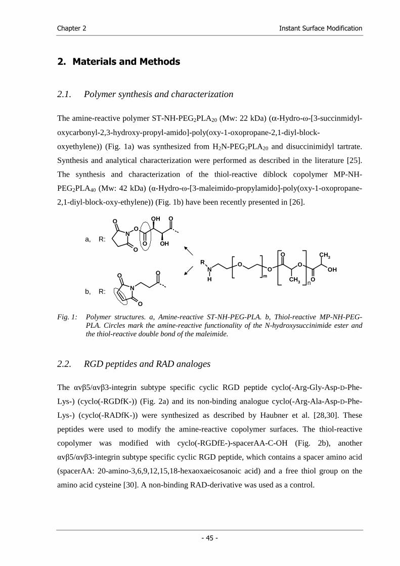
Chapter 2 Instant Surface Modification
- 45 -
2. Materials and Methods
2.1. Polymer synthesis and characterization
The amine-reactive polymer ST-NH-PEG2PLA20 (Mw: 22 kDa) (α-Hydro-ω-[3-succinmidyl-
oxycarbonyl-2,3-hydroxy-propyl-amido]-poly(oxy-1-oxopropane-2,1-diyl-block-
oxyethylene)) (Fig. 1a) was synthesized from H2N-PEG2PLA20 and disuccinimidyl tartrate.
Synthesis and analytical characterization were performed as described in the literature [25].
The synthesis and characterization of the thiol-reactive diblock copolymer MP-NH-
PEG2PLA40 (Mw: 42 kDa) (α-Hydro-ω-[3-maleimido-propylamido]-poly(oxy-1-oxopropane-
2,1-diyl-block-oxy-ethylene)) (Fig. 1b) have been recently presented in [26].
a, R:
b, R:
OHO
O
CH3
O
O
O
CH3
m
N
H
R
n
NO
O
OH
OH
OO
O
N
OO
O Fig. 1: Polymer structures. a, Amine-reactive ST-NH-PEG-PLA. b, Thiol-reactive MP-NH-PEG-
PLA. Circles mark the amine-reactive functionality of the N-hydroxysuccinimide ester and the thiol-reactive double bond of the maleimide.
2.2. RGD peptides and RAD analoges
The αvβ5/αvβ3-integrin subtype specific cyclic RGD peptide cyclo(-Arg-Gly-Asp-D-Phe-
Lys-) (cyclo(-RGDfK-)) (Fig. 2a) and its non-binding analogue cyclo(-Arg-Ala-Asp-D-Phe-
Lys-) (cyclo(-RADfK-)) were synthesized as described by Haubner et al. [28,30]. These
peptides were used to modify the amine-reactive copolymer surfaces. The thiol-reactive
copolymer was modified with cyclo(-RGDfE-)-spacerAA-C-OH (Fig. 2b), another
αvβ5/αvβ3-integrin subtype specific cyclic RGD peptide, which contains a spacer amino acid
(spacerAA: 20-amino-3,6,9,12,15,18-hexaoxaeicosanoic acid) and a free thiol group on the
amino acid cysteine [30]. A non-binding RAD-derivative was used as a control.
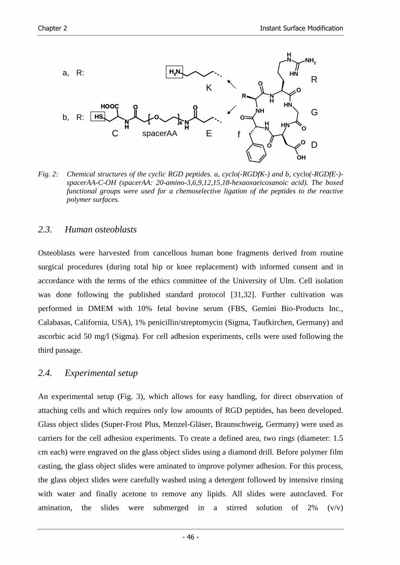
Chapter 2 Instant Surface Modification
- 46 -
NH
NH
NH NH
NH
O
O
O
O
O
O
OH
NH
NH2
NH
R
NH
O
ONH
O
SH
HOOC
6 NH
O
ONH
O
SH
HOOC
6
NH2NH2
R
G
D
a, R:
b, R:
f
K
C spacerAA E
Fig. 2: Chemical structures of the cyclic RGD peptides. a, cyclo(-RGDfK-) and b, cyclo(-RGDfE-)-
spacerAA-C-OH (spacerAA: 20-amino-3,6,9,12,15,18-hexaoxaeicosanoic acid). The boxed functional groups were used for a chemoselective ligation of the peptides to the reactive polymer surfaces.
2.3. Human osteoblasts
Osteoblasts were harvested from cancellous human bone fragments derived from routine
surgical procedures (during total hip or knee replacement) with informed consent and in
accordance with the terms of the ethics committee of the University of Ulm. Cell isolation
was done following the published standard protocol [31,32]. Further cultivation was
performed in DMEM with 10% fetal bovine serum (FBS, Gemini Bio-Products Inc.,
Calabasas, California, USA), 1% penicillin/streptomycin (Sigma, Taufkirchen, Germany) and
ascorbic acid 50 mg/l (Sigma). For cell adhesion experiments, cells were used following the
third passage.
2.4. Experimental setup
An experimental setup (Fig. 3), which allows for easy handling, for direct observation of
attaching cells and which requires only low amounts of RGD peptides, has been developed.
Glass object slides (Super-Frost Plus, Menzel-Gläser, Braunschweig, Germany) were used as
carriers for the cell adhesion experiments. To create a defined area, two rings (diameter: 1.5
cm each) were engraved on the glass object slides using a diamond drill. Before polymer film
casting, the glass object slides were aminated to improve polymer adhesion. For this process,
the glass object slides were carefully washed using a detergent followed by intensive rinsing
with water and finally acetone to remove any lipids. All slides were autoclaved. For
amination, the slides were submerged in a stirred solution of 2% (v/v)
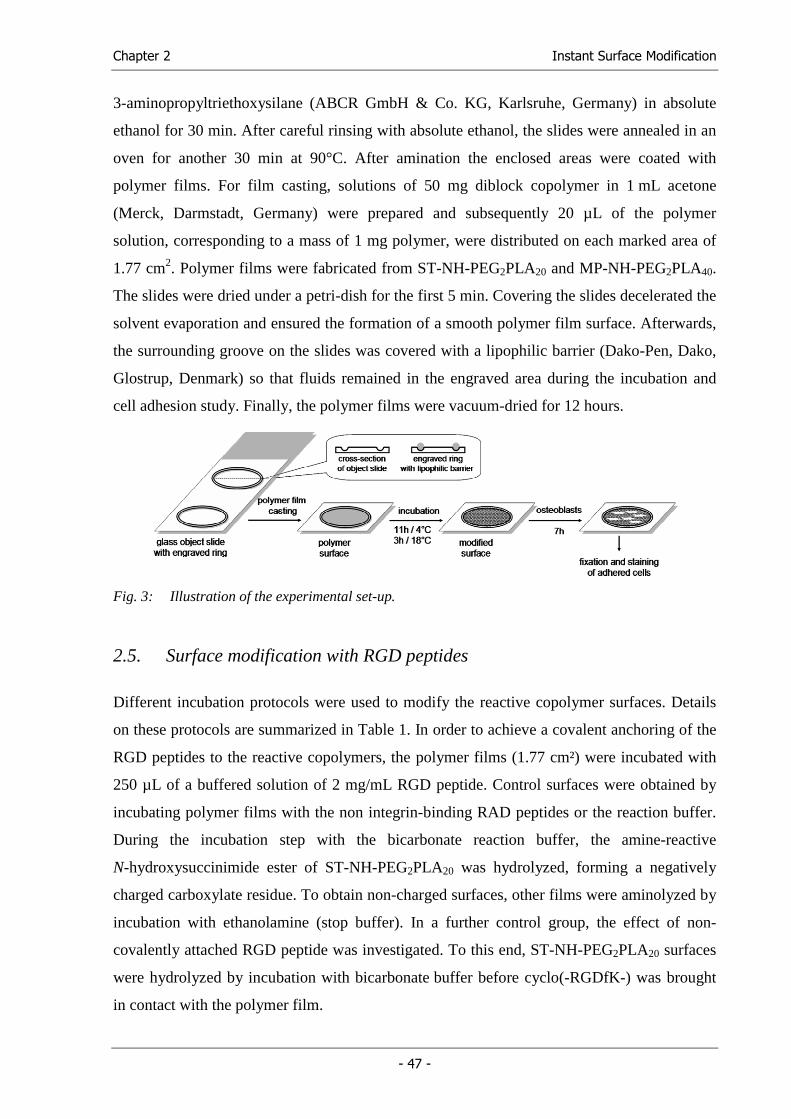
Chapter 2 Instant Surface Modification
- 47 -
3-aminopropyltriethoxysilane (ABCR GmbH & Co. KG, Karlsruhe, Germany) in absolute
ethanol for 30 min. After careful rinsing with absolute ethanol, the slides were annealed in an
oven for another 30 min at 90°C. After amination the enclosed areas were coated with
polymer films. For film casting, solutions of 50 mg diblock copolymer in 1 mL acetone
(Merck, Darmstadt, Germany) were prepared and subsequently 20 µL of the polymer
solution, corresponding to a mass of 1 mg polymer, were distributed on each marked area of
1.77 cm2. Polymer films were fabricated from ST-NH-PEG2PLA20 and MP-NH-PEG2PLA40.
The slides were dried under a petri-dish for the first 5 min. Covering the slides decelerated the
solvent evaporation and ensured the formation of a smooth polymer film surface. Afterwards,
the surrounding groove on the slides was covered with a lipophilic barrier (Dako-Pen, Dako,
Glostrup, Denmark) so that fluids remained in the engraved area during the incubation and
cell adhesion study. Finally, the polymer films were vacuum-dried for 12 hours.
Fig. 3: Illustration of the experimental set-up.
2.5. Surface modification with RGD peptides
Different incubation protocols were used to modify the reactive copolymer surfaces. Details
on these protocols are summarized in Table 1. In order to achieve a covalent anchoring of the
RGD peptides to the reactive copolymers, the polymer films (1.77 cm²) were incubated with
250 µL of a buffered solution of 2 mg/mL RGD peptide. Control surfaces were obtained by
incubating polymer films with the non integrin-binding RAD peptides or the reaction buffer.
During the incubation step with the bicarbonate reaction buffer, the amine-reactive
N-hydroxysuccinimide ester of ST-NH-PEG2PLA20 was hydrolyzed, forming a negatively
charged carboxylate residue. To obtain non-charged surfaces, other films were aminolyzed by
incubation with ethanolamine (stop buffer). In a further control group, the effect of non-
covalently attached RGD peptide was investigated. To this end, ST-NH-PEG2PLA20 surfaces
were hydrolyzed by incubation with bicarbonate buffer before cyclo(-RGDfK-) was brought
in contact with the polymer film.
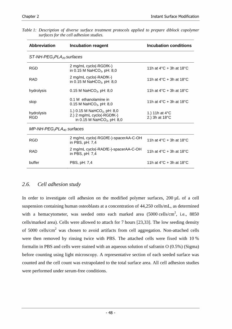
Chapter 2 Instant Surface Modification
- 48 -
Table 1: Description of diverse surface treatment protocols applied to prepare diblock copolymer surfaces for the cell adhesion studies.
Abbreviation Incubation reagent Incubation conditions
ST-NH-PEG2PLA20 surfaces
RGD 2 mg/mL cyclo(-RGDfK-) in 0.15 M NaHCO3, pH: 8,0
11h at 4°C + 3h at 18°C
RAD 2 mg/mL cyclo(-RADfK-) in 0.15 M NaHCO3, pH: 8,0
11h at 4°C + 3h at 18°C
hydrolysis 0.15 M NaHCO3, pH: 8,0 11h at 4°C + 3h at 18°C
stop 0.1 M ethanolamine in 0.15 M NaHCO3, pH: 8,0
11h at 4°C + 3h at 18°C
hydrolysis RGD
1.) 0.15 M NaHCO3, pH: 8,0 2.) 2 mg/mL cyclo(-RGDfK-) in 0.15 M NaHCO3, pH: 8,0
1.) 11h at 4°C 2.) 3h at 18°C
MP-NH-PEG2PLA40 surfaces
RGD 2 mg/mL cyclo(-RGDfE-)-spacerAA-C-OH in PBS, pH: 7,4
11h at 4°C + 3h at 18°C
RAD 2 mg/mL cyclo(-RADfE-)-spacerAA-C-OH in PBS, pH: 7,4
11h at 4°C + 3h at 18°C
buffer PBS, pH: 7,4 11h at 4°C + 3h at 18°C
2.6. Cell adhesion study
In order to investigate cell adhesion on the modified polymer surfaces, 200 µL of a cell
suspension containing human osteoblasts at a concentration of 44,250 cells/mL, as determined
with a hemacytometer, was seeded onto each marked area (5000 cells/cm2, i.e., 8850
cells/marked area). Cells were allowed to attach for 7 hours [23,33]. The low seeding density
of 5000 cells/cm2 was chosen to avoid artifacts from cell aggregation. Non-attached cells
were then removed by rinsing twice with PBS. The attached cells were fixed with 10 %
formalin in PBS and cells were stained with an aqueous solution of safranin O (0.5%) (Sigma)
before counting using light microscopy. A representative section of each seeded surface was
counted and the cell count was extrapolated to the total surface area. All cell adhesion studies
were performed under serum-free conditions.
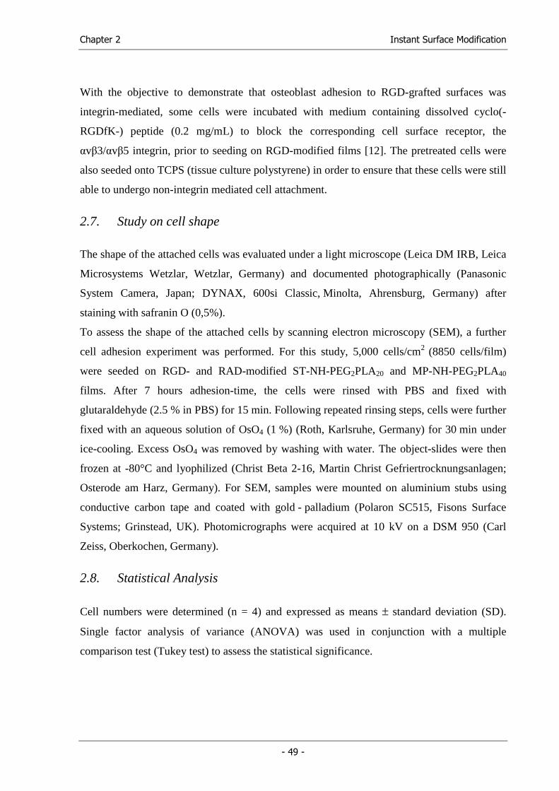
Chapter 2 Instant Surface Modification
- 49 -
With the objective to demonstrate that osteoblast adhesion to RGD-grafted surfaces was
integrin-mediated, some cells were incubated with medium containing dissolved cyclo(-
RGDfK-) peptide (0.2 mg/mL) to block the corresponding cell surface receptor, the
αvβ3/αvβ5 integrin, prior to seeding on RGD-modified films [12]. The pretreated cells were
also seeded onto TCPS (tissue culture polystyrene) in order to ensure that these cells were still
able to undergo non-integrin mediated cell attachment.
2.7. Study on cell shape
The shape of the attached cells was evaluated under a light microscope (Leica DM IRB, Leica
Microsystems Wetzlar, Wetzlar, Germany) and documented photographically (Panasonic
System Camera, Japan; DYNAX, 600si Classic, Minolta, Ahrensburg, Germany) after
staining with safranin O (0,5%).
To assess the shape of the attached cells by scanning electron microscopy (SEM), a further
cell adhesion experiment was performed. For this study, 5,000 cells/cm2 (8850 cells/film)
were seeded on RGD- and RAD-modified ST-NH-PEG2PLA20 and MP-NH-PEG2PLA40
films. After 7 hours adhesion-time, the cells were rinsed with PBS and fixed with
glutaraldehyde (2.5 % in PBS) for 15 min. Following repeated rinsing steps, cells were further
fixed with an aqueous solution of OsO4 (1 %) (Roth, Karlsruhe, Germany) for 30 min under
ice-cooling. Excess OsO4 was removed by washing with water. The object-slides were then
frozen at -80°C and lyophilized (Christ Beta 2-16, Martin Christ Gefriertrocknungsanlagen;
Osterode am Harz, Germany). For SEM, samples were mounted on aluminium stubs using
conductive carbon tape and coated with gold - palladium (Polaron SC515, Fisons Surface
Systems; Grinstead, UK). Photomicrographs were acquired at 10 kV on a DSM 950 (Carl
Zeiss, Oberkochen, Germany).
2.8. Statistical Analysis
Cell numbers were determined (n = 4) and expressed as means ± standard deviation (SD).
Single factor analysis of variance (ANOVA) was used in conjunction with a multiple
comparison test (Tukey test) to assess the statistical significance.
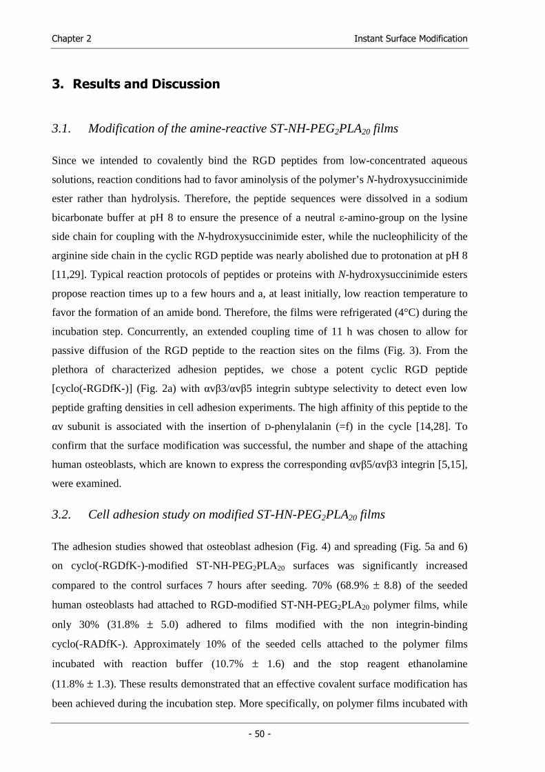
Chapter 2 Instant Surface Modification
- 50 -
3. Results and Discussion
3.1. Modification of the amine-reactive ST-NH-PEG2PLA20 films
Since we intended to covalently bind the RGD peptides from low-concentrated aqueous
solutions, reaction conditions had to favor aminolysis of the polymer’s N-hydroxysuccinimide
ester rather than hydrolysis. Therefore, the peptide sequences were dissolved in a sodium
bicarbonate buffer at pH 8 to ensure the presence of a neutral ε-amino-group on the lysine
side chain for coupling with the N-hydroxysuccinimide ester, while the nucleophilicity of the
arginine side chain in the cyclic RGD peptide was nearly abolished due to protonation at pH 8
[11,29]. Typical reaction protocols of peptides or proteins with N-hydroxysuccinimide esters
propose reaction times up to a few hours and a, at least initially, low reaction temperature to
favor the formation of an amide bond. Therefore, the films were refrigerated (4°C) during the
incubation step. Concurrently, an extended coupling time of 11 h was chosen to allow for
passive diffusion of the RGD peptide to the reaction sites on the films (Fig. 3). From the
plethora of characterized adhesion peptides, we chose a potent cyclic RGD peptide
[cyclo(-RGDfK-)] (Fig. 2a) with αvβ3/αvβ5 integrin subtype selectivity to detect even low
peptide grafting densities in cell adhesion experiments. The high affinity of this peptide to the
αv subunit is associated with the insertion of D-phenylalanin (=f) in the cycle [14,28]. To
confirm that the surface modification was successful, the number and shape of the attaching
human osteoblasts, which are known to express the corresponding αvβ5/αvβ3 integrin [5,15],
were examined.
3.2. Cell adhesion study on modified ST-HN-PEG2PLA20 films
The adhesion studies showed that osteoblast adhesion (Fig. 4) and spreading (Fig. 5a and 6)
on cyclo(-RGDfK-)-modified ST-NH-PEG2PLA20 surfaces was significantly increased
compared to the control surfaces 7 hours after seeding. 70% (68.9% ± 8.8) of the seeded
human osteoblasts had attached to RGD-modified ST-NH-PEG2PLA20 polymer films, while
only 30% (31.8% ± 5.0) adhered to films modified with the non integrin-binding
cyclo(-RADfK-). Approximately 10% of the seeded cells attached to the polymer films
incubated with reaction buffer (10.7% ± 1.6) and the stop reagent ethanolamine
(11.8% ± 1.3). These results demonstrated that an effective covalent surface modification has
been achieved during the incubation step. More specifically, on polymer films incubated with
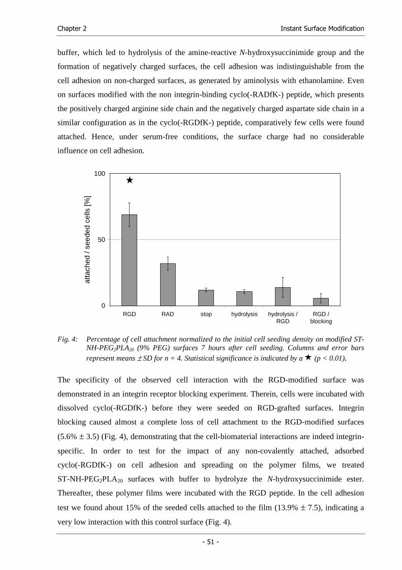
Chapter 2 Instant Surface Modification
- 51 -
buffer, which led to hydrolysis of the amine-reactive N-hydroxysuccinimide group and the
formation of negatively charged surfaces, the cell adhesion was indistinguishable from the
cell adhesion on non-charged surfaces, as generated by aminolysis with ethanolamine. Even
on surfaces modified with the non integrin-binding cyclo(-RADfK-) peptide, which presents
the positively charged arginine side chain and the negatively charged aspartate side chain in a
similar configuration as in the cyclo(-RGDfK-) peptide, comparatively few cells were found
attached. Hence, under serum-free conditions, the surface charge had no considerable
influence on cell adhesion.
0
50
100
RGD RAD stop hydrolysis hydrolysis /RGD
RGD /blocking
atta
ched
/ se
eded
cel
ls [%
]
Fig. 4: Percentage of cell attachment normalized to the initial cell seeding density on modified ST-
NH-PEG2PLA20 (9% PEG) surfaces 7 hours after cell seeding. Columns and error bars
represent means ± SD for n = 4. Statistical significance is indicated by a (p < 0.01).
The specificity of the observed cell interaction with the RGD-modified surface was
demonstrated in an integrin receptor blocking experiment. Therein, cells were incubated with
dissolved cyclo(-RGDfK-) before they were seeded on RGD-grafted surfaces. Integrin
blocking caused almost a complete loss of cell attachment to the RGD-modified surfaces
(5.6% ± 3.5) (Fig. 4), demonstrating that the cell-biomaterial interactions are indeed integrin-
specific. In order to test for the impact of any non-covalently attached, adsorbed
cyclo(-RGDfK-) on cell adhesion and spreading on the polymer films, we treated
ST-NH-PEG2PLA20 surfaces with buffer to hydrolyze the N-hydroxysuccinimide ester.
Thereafter, these polymer films were incubated with the RGD peptide. In the cell adhesion
test we found about 15% of the seeded cells attached to the film (13.9% ± 7.5), indicating a
very low interaction with this control surface (Fig. 4).
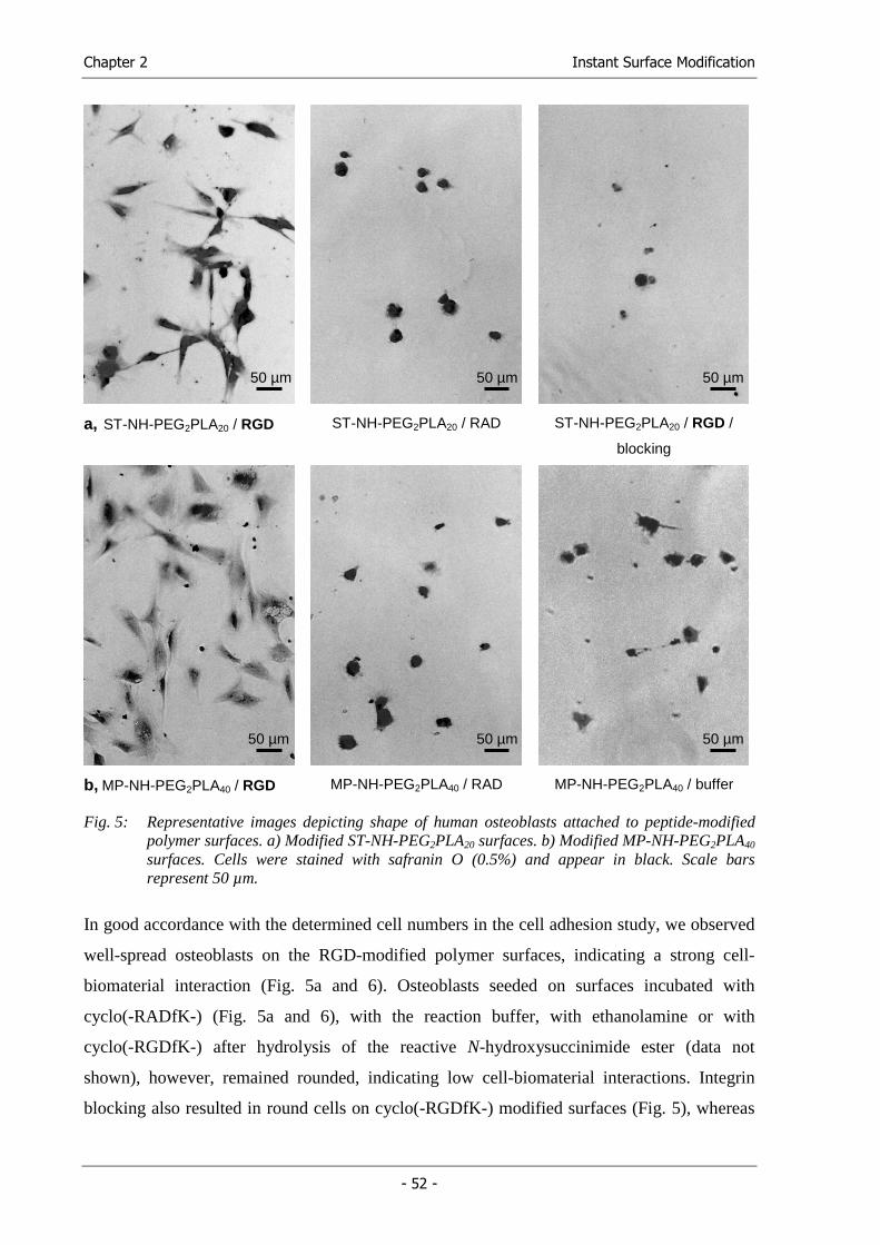
Chapter 2 Instant Surface Modification
- 52 -
a, ST-NH-PEG2PLA20 / RGD ST-NH-PEG2PLA20 / RAD ST-NH-PEG2PLA20 / RGD /
blocking
b, MP-NH-PEG2PLA40 / RGD MP-NH-PEG2PLA40 / RAD MP-NH-PEG2PLA40 / buffer
Fig. 5: Representative images depicting shape of human osteoblasts attached to peptide-modified polymer surfaces. a) Modified ST-NH-PEG2PLA20 surfaces. b) Modified MP-NH-PEG2PLA40 surfaces. Cells were stained with safranin O (0.5%) and appear in black. Scale bars represent 50 µm.
In good accordance with the determined cell numbers in the cell adhesion study, we observed
well-spread osteoblasts on the RGD-modified polymer surfaces, indicating a strong cell-
biomaterial interaction (Fig. 5a and 6). Osteoblasts seeded on surfaces incubated with
cyclo(-RADfK-) (Fig. 5a and 6), with the reaction buffer, with ethanolamine or with
cyclo(-RGDfK-) after hydrolysis of the reactive N-hydroxysuccinimide ester (data not
shown), however, remained rounded, indicating low cell-biomaterial interactions. Integrin
blocking also resulted in round cells on cyclo(-RGDfK-) modified surfaces (Fig. 5), whereas
50 µm 50 µm 50 µm
50 µm 50 µm 50 µm
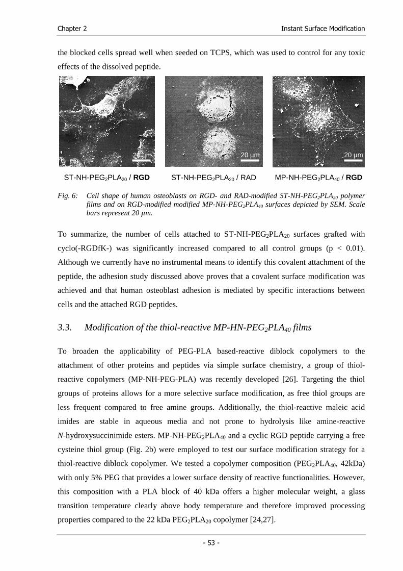
Chapter 2 Instant Surface Modification
- 53 -
the blocked cells spread well when seeded on TCPS, which was used to control for any toxic
effects of the dissolved peptide.
ST-NH-PEG2PLA20 / RGD ST-NH-PEG2PLA20 / RAD MP-NH-PEG2PLA40 / RGD
Fig. 6: Cell shape of human osteoblasts on RGD- and RAD-modified ST-NH-PEG2PLA20 polymer films and on RGD-modified modified MP-NH-PEG2PLA40 surfaces depicted by SEM. Scale bars represent 20 µm.
To summarize, the number of cells attached to ST-NH-PEG2PLA20 surfaces grafted with
cyclo(-RGDfK-) was significantly increased compared to all control groups (p < 0.01).
Although we currently have no instrumental means to identify this covalent attachment of the
peptide, the adhesion study discussed above proves that a covalent surface modification was
achieved and that human osteoblast adhesion is mediated by specific interactions between
cells and the attached RGD peptides.
3.3. Modification of the thiol-reactive MP-HN-PEG2PLA40 films
To broaden the applicability of PEG-PLA based-reactive diblock copolymers to the
attachment of other proteins and peptides via simple surface chemistry, a group of thiol-
reactive copolymers (MP-NH-PEG-PLA) was recently developed [26]. Targeting the thiol
groups of proteins allows for a more selective surface modification, as free thiol groups are
less frequent compared to free amine groups. Additionally, the thiol-reactive maleic acid
imides are stable in aqueous media and not prone to hydrolysis like amine-reactive
N-hydroxysuccinimide esters. MP-NH-PEG2PLA40 and a cyclic RGD peptide carrying a free
cysteine thiol group (Fig. 2b) were employed to test our surface modification strategy for a
thiol-reactive diblock copolymer. We tested a copolymer composition (PEG2PLA40, 42kDa)
with only 5% PEG that provides a lower surface density of reactive functionalities. However,
this composition with a PLA block of 40 kDa offers a higher molecular weight, a glass
transition temperature clearly above body temperature and therefore improved processing
properties compared to the 22 kDa PEG2PLA20 copolymer [24,27].
20 µm 20 µm 20 µm
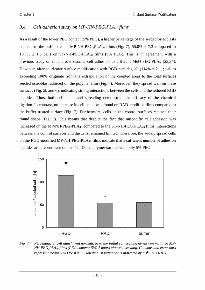
Chapter 2 Instant Surface Modification
- 54 -
3.4. Cell adhesion study on MP-HN-PEG2PLA40 films
As a result of the lower PEG content (5% PEG), a higher percentage of the seeded osteoblasts
adhered to the buffer treated MP-NH-PEG2PLA40 films (Fig. 7), 55.0% ± 7.3 compared to
10.7% ± 1.6 cells on ST-NH-PEG2PLA20 films (9% PEG). This is in agreement with a
previous study on rat marrow stromal cell adhesion to different MeO-PEG-PLAs [23,34].
However, after solid-state surface modification with RGD peptides, all (114% ± 21.1; values
exceeding 100% originate from the extrapolation of the counted areas to the total surface)
seeded osteoblast adhered on the polymer film (Fig. 7). Moreover, they spread well on these
surfaces (Fig. 5b and 6), indicating strong interactions between the cells and the tethered RGD
peptides. Thus, both cell count and spreading demonstrate the efficacy of the chemical
ligation. In contrast, no increase in cell count was found on RAD-modified films compared to
the buffer treated surface (Fig. 7). Furthermore, cells on the control surfaces retained their
round shape (Fig. 5). This means that despite the fact that unspecific cell adhesion was
increased on the MP-NH-PEG2PLA40 compared to the ST-NH-PEG2PLA20 films, interactions
between the control surfaces and the cells remained limited. Therefore, the widely spread cells
on the RGD-modified MP-NH-PEG2PLA40 films indicate that a sufficient number of adhesion
peptides are present even on this 42 kDa copolymer surface with only 5% PEG.
0
50
100
150
RGD RAD buffer
atta
ched
/ se
eded
cel
ls [%
]
Fig. 7: Percentage of cell attachment normalized to the initial cell seeding density on modified MP-
NH-PEG2PLA40 films (PEG content: 5%) 7 hours after cell seeding. Columns and error bars
represent means ± SD for n = 3. Statistical significance is indicated by a (p < 0.01).
Chapter 2 Instant Surface Modification
- 55 -
4. Conclusions
In conclusion, we showed the instant surface modification of preformed polymer films with
high affinity adhesion peptides via two different linkers. The modification of low adhesive
polymer films was performed by the simple incubation of amine- and thiol-reactive diblock
copolymers, consisting of a reactive PEG and a PLA block. Although unspecific cell adhesion
was shown to depend on the PEG content of the diblock copolymers, even MP-NH-
PEG2PLA40 (5% PEG) displayed a sufficient density of reactive groups to provide for specific
interactions with the αvβ5/αvβ3 integrin on human osteoblasts. As these reactive copolymers
offer several modification options as well as variable mechanical properties and rates of
biodegradation, these materials appear to be well suited to various customized applications in
the field of tissue engineering and implant technology.
5. Acknowledgements
The authors thank the Bayerische Forschungsstiftung (ForTePro) for their financial support.
Special thanks are due to Allison Dennis, Department of Biomedical Engineering, Georgia
Institute of Technology, Atlanta, GA, USA, for proof-reading.
Chapter 2 Instant Surface Modification
- 56 -
6. References
(1) LeBaron RG, Athanasiou KA. 'Extracellular matrix cell adhesion peptides: functional applications in orthopedic materials'. Tissue Eng (2000); 6: 85-103.
(2) Shakesheff KM, Cannizzaro SM, Langer R. 'Creating biomimetic micro-environments with synthetic polymer-peptide hybrid molecules'. J Biomater Sci Polym Ed (1998); 9: 507-518.
(3) Hu Y, Winn SR, Krajbich I, Hollinger JO. 'Porous polymer scaffolds surface-modified with arginine-glycine-aspartic acid-cysteine enhance bone cell attachment and differentiation in vitro'. J Biomed Mater Res (2003); 64A: 583-590.
(4) Schaffner P, Meyer J, Dard M, Wenz R, Nies B, Verrier S, Kessler H, Kantlehner M. 'Induced tissue integration of bone implants by coating with bone selective RGD-peptides in vitro and in vivo studies'. J Mater Sci Mater Med (1999); 10: 837-839.
(5) Gronthos S, Stewart K, Graves SE, Hay S, Simmons PJ. 'Integrin expression and function on human osteoblast-like cells'. J Bone Miner Res (1997); 12: 1189-1197.
(6) Ruoslahti E. 'RGD and other recognition sequences for integrins'. Annu Rev Cell Dev Biol (1996); 12: 697-715.
(7) Schaffner P, Dard MM. 'Structure and function of RGD peptides involved in bone biology'. Cell Mol Life Sci (2003); 60: 119-132.
(8) Aumailley M, Gurrath M, Muller G, Calvete J, Timpl R, Kessler H. 'Arg-Gly-Asp constrained within cyclic pentapeptides. Strong and selective inhibitors of cell adhesion to vitronectin and laminin fragment P1'. FEBS Lett (1991); 291: 50-54.
(9) Hersel U, Dahmen C, Kessler H. 'RGD modified polymers: biomaterials for stimulated cell adhesion and beyond'. Biomaterials (2003); 24: 4385-4415.
(10) Massia SP, Stark J. 'Immobilized RGD peptides on surface-grafted dextran promote biospecific cell attachment'. J Biomed Mater Res (2001); 56: 390-399.
(11) Hern DL, Hubbell JA. 'Incorporation of adhesion peptides into nonadhesive hydrogels useful for tissue resurfacing'. J Biomed Mater Res (1998); 39: 266-276.
(12) Shin H, Jo S, Mikos AG. 'Modulation of marrow stromal osteoblast adhesion on biomimetic oligo[poly(ethylene glycol) fumarate] hydrogels modified with Arg-Gly-Asp peptides and a poly(ethyleneglycol) spacer'. J Biomed Mater Res (2002); 61: 169-179.
(13) Cannizzaro SM, Padera RF, Langer R, Rogers RA, Black FE, Davies MC, Tendler SJ, Shakesheff KM. 'A novel biotinylated degradable polymer for cell-interactive applications'. Biotechnol Bioeng (1998); 58: 529-535.
(14) Kantlehner M, Schaffner P, Finsinger D, Meyer J, Jonczyk A, Diefenbach B, Nies B, Holzemann G, Goodman SL, Kessler H. 'Surface coating with cyclic RGD peptides
Chapter 2 Instant Surface Modification
- 57 -
stimulates osteoblast adhesion and proliferation as well as bone formation'. ChemBioChem (2000); 1: 107-114.
(15) Kantlehner M, Finsinger D, Meyer J, Schaffner P, Jonczyk A, Diefenbach B, Nies B, Kessler H. 'Selective RGD-mediated adhesion of osteoblasts at surfaces of implants'. Angew Chem Int Ed Engl (1999); 38: 560-562.
(16) Anselme K. 'Osteoblast adhesion on biomaterials'. Biomaterials (2000); 21: 667-681.
(17) Stile RA, Burghardt WR, Healy KE. 'Synthesis and characterization of injectable poly(N-isopropylacrylamide)-based hydrogels that support tissue formation in vitro'. Macromolecules (1999); 32: 7370-7379.
(18) Rowley JA, Madlambayan G, Mooney DJ. 'Alginate hydrogels as synthetic extracellular matrix materials'. Biomaterials (1999); 20: 45-53.
(19) Burdick JA, Anseth KS. 'Photoencapsulation of osteoblasts in injectable RGD-modified PEG hydrogels for bone tissue engineering'. Biomaterials (2002); 23: 4315-4323.
(20) Ishaug SL, Crane GM, Miller MJ, Yasko AW, Yaszemski MJ, Mikos AG. 'Bone formation by three-dimensional stromal osteoblast culture in biodegradable polymer scaffolds'. J Biomed Mater Res (1997); 36: 17-28.
(21) Schaefer D, Martin I, Shastri P, Padera RF, Langer R, Freed LE, Vunjak-Novakovic G. 'In vitro generation of osteochondral composites'. Biomaterials (2000); 21: 2599-2606.
(22) Gref R, Luck M, Quellec P, Marchand M, Dellacherie E, Harnisch S, Blunk T, Muller RH. ''Stealth' corona-core nanoparticles surface modified by polyethylene glycol (PEG): Influences of the corona (PEG chain length and surface density) and of the core composition on phagocytic uptake and plasma protein adsorption'. Colloids Surf, B (2000); 18: 301-313.
(23) Lieb E, Tessmar J, Hacker M, Fischbach C, Rose D, Blunk T, Mikos AG, Gopferich A, Schulz MB. 'Poly(D,L-lactic acid)-poly(ethylene glycol)-monomethyl ether diblock copolymers control adhesion and osteoblastic differentiation of marrow stromal cells'. Tissue Eng (2003); 9: 71-84.
(24) Lucke A, Tessmar J, Schnell E, Schmeer G, Gopferich A. 'Biodegradable poly(,-lactic acid)-poly(ethylene glycol)-monomethyl ether diblock copolymers: structures and surface properties relevant to their use as biomaterials'. Biomaterials (2000); 21: 2361-2370.
(25) Tessmar JK, Mikos AG, Gopferich A. 'Amine-reactive biodegradable diblock copolymers'. Biomacromolecules (2002); 3: 194-200.
(26) Tessmar J, Mikos A, Gopferich A. 'The use of poly(ethylene glycol)-block-poly(lactic acid) derived copolymers for the rapid creation of biomimetic surfaces'. Biomaterials (2003); 24: 4475-4486.
(27) Hacker M, Tessmar J, Neubauer M, Blaimer A, Blunk T, Gopferich A, Schulz MB. 'Towards biomimetic scaffolds: Anhydrous scaffold fabrication from biodegradable amine-reactive diblock copolymers'. Biomaterials (2003); 24: 4459-4473.
Chapter 2 Instant Surface Modification
- 58 -
(28) Haubner R, Gratias R, Diefenbach B, Goodman SL, Jonczyk A, Kessler H. 'Structural and Functional Aspects of RGD-Containing Cyclic Pentapeptides as Highly Potent and Selective Integrin aVb3 Antagonists'. J Am Chem Soc (1996); 118: 7461-7472.
(29) Besselink GAJ, Beugeling T, Bantjes A. 'N-Hydroxysuccinimide-Activated Glycine-Sepharose - Hydrolysis of Activated Groups and Coupling of Amino-Compounds.'. App Biochem Biotech (1993); 43: 227-246.
(30) Hersel, Ulrich. 'Monomeric and Multimeric RGD Peptides for Integrin mediated Cell Adhesion on Biomaterials and for Tumor Diagnostics'. Ph.D. Thesis. Technische Universität München, Institut für Organische Chemie und Biochemie. (2003)
(31) Mayr-Wohlfart U, Kessler S, Puhl W, Gunther KP, Knochel W. 'BMP-4 of Xenopus laevis stimulates differentiation of human primary osteoblast-like cells'. J Bone Joint Surg Br (2001); 83: 144-147.
(32) Mörike M, Schulz M, Nerlich A, Koschnik M, Teller WM, Vetter U, Brenner RE. 'Expression of osteoblastic markers in cultured human bone and fracture callus cells'. J Mol Med (1995); 73: 571-575.
(33) Ishaug SL, Yaszemski MJ, Bizios R, Mikos AG. 'Osteoblast function on synthetic biodegradable polymers'. J Biomed Mater Res (1994); 28: 1445-1453.
(34) Gopferich A, Peter SJ, Lucke A, Lu L, Mikos AG. 'Modulation of marrow stromal cell function using poly(D,L-lactic acid)-block-poly(ethylene glycol)-monomethyl ether surfaces'. J Biomed Mater Res (1999); 46: 390-398.
Functional Cell Carriers for Tissue Engineering
Chapter 3
Towards Biomimetic Scaffolds: Anhydrous Scaffold Fabrication from
Biodegradable Amine-reactive Diblock Copolymers
Michael Hacker, Jörg Tessmar, Markus Neubauer, Andrea Blaimer,
Torsten Blunk, Achim Göpferich, Michaela B. Schulz
Department of Pharmaceutical Technology, University of Regensburg, 93040 Regensburg, Germany
Biomaterials 24 (2003), 4459-4473
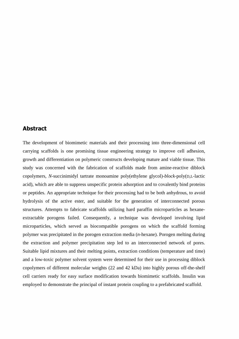
Abstract
The development of biomimetic materials and their processing into three-dimensional cell
carrying scaffolds is one promising tissue engineering strategy to improve cell adhesion,
growth and differentiation on polymeric constructs developing mature and viable tissue. This
study was concerned with the fabrication of scaffolds made from amine-reactive diblock
copolymers, N-succinimidyl tartrate monoamine poly(ethylene glycol)-block-poly(D,L-lactic
acid), which are able to suppress unspecific protein adsorption and to covalently bind proteins
or peptides. An appropriate technique for their processing had to be both anhydrous, to avoid
hydrolysis of the active ester, and suitable for the generation of interconnected porous
structures. Attempts to fabricate scaffolds utilizing hard paraffin microparticles as hexane-
extractable porogens failed. Consequently, a technique was developed involving lipid
microparticles, which served as biocompatible porogens on which the scaffold forming
polymer was precipitated in the porogen extraction media (n-hexane). Porogen melting during
the extraction and polymer precipitation step led to an interconnected network of pores.
Suitable lipid mixtures and their melting points, extraction conditions (temperature and time)
and a low-toxic polymer solvent system were determined for their use in processing diblock
copolymers of different molecular weights (22 and 42 kDa) into highly porous off-the-shelf
cell carriers ready for easy surface modification towards biomimetic scaffolds. Insulin was
employed to demonstrate the principal of instant protein coupling to a prefabricated scaffold.
Chapter 3 Towards biomimetic scaffolds
- 61 -
1. Introduction
One major aim in tissue engineering is the development of transplantable tissue by seeding,
proliferation and differentiation of isolated cells on biodegradable polymeric carriers [1].
Modifying the surface of such carriers in order to control the response of attached cells has
proven to be a valuable tool for improving the development of mature and viable tissue [2,3].
For this purpose, adhesion proteins, their peptide motives [4-7] and growth factors [8-10]
have been covalently bound to biomaterial surfaces. However, only few studies, primarily on
hydrogels [11,12], transferred this concept beyond two-dimensions to three-dimensional
applications, such as cell carrying scaffolds.
Control of surface composition and cell behavior through bound bioactive substances requires
consideration of dynamic surface changes caused by the adsorption of serum proteins when
the modified materials come into contact with body fluids. To this end, we have utilized
diblock copolymers, consisting of a biodegradable lipophilic polymer block and a hydrophilic
block to limit or suppress the non-specific adsorption process and concomitant
disadvantageous side effects [13-15]. A biocompatible organic link, e.g. tartaric acid
N-hydroxysuccinimide ester, which is capable of covalently binding biologically active
molecules bearing free amine groups, was attached to the hydrophilic block in order to create
a new class of non-adsorbing, amine-reactive polymers [16]. N-hydroxysuccinimide esters are
among the most frequently used agents for protein crosslinking, labeling [17] and conjugation
with PEG [18,19] under formation of stable amide linkages. Furthermore, they can be stored
under moisture exclusive conditions for extended periods of time. Therefore, these amine-
reactive diblock copolymers, carrying N-hydroxysuccinimide esters, are designed to be
processed in their active state making amine-reactive off-the-shelf scaffolds available [16].
Finally, the surface of such pre-fabricated scaffolds can be modified just before use, by
covalently binding proteins or peptides in an instantaneous manner, i.e. by simply incubating
the polymeric construct with an aqueous solution containing the selected biomolecules. Such
amine-reactive diblock copolymers, N-succinimidyl tartrate monoamine poly(ethylene
glycol)-block-poly(D,L-lactic acid), with different block ratios, were recently synthesized in
our group [16].
The study presented here aimed at the development of a technique for processing these
polymers into scaffolds, which play a prominent role in tissue engineering since they provide
a three-dimensional framework for cells to attach, proliferate and lay down extracellular
matrix. This concept demands a highly porous and interconnected scaffold structure to ensure
Chapter 3 Towards biomimetic scaffolds
- 62 -
sufficient space for tissue development and unimpaired diffusion of nutrients, oxygen and
waste [20,21]. Processing amine-reactive polymers into scaffolds required consideration of
two essential points: firstly, in order to preserve the active group from hydrolysis, aqueous
media had to be avoided, and secondly, a sufficient surface density of reactive PEG-chains
demands a low molecular weight PLA-block (20 to 40 kDa) [15]. Thus, we required an
anhydrous, lab-scale scaffold fabrication technique, which would be suitable for processing
low molecular weight polymers into highly porous scaffolds and would provide an
interconnected pore structure.
Numerous methods for polymer processing into three-dimensional scaffolds have been
described, according to the literature, such as polymer casting-salt leaching with or without
subsequent compression molding [22-24], phase separation and gas foaming [25,26]. None of
these methods, however, met all the demands listed above. Recently, two anhydrous
processing techniques based on particulate leaching were published. Both involved hard
paraffin microparticles prepared as pore forming devices [27,28]. One method started from a
dispersion of such paraffin microparticles in a polymer solution and finally led to scaffolds
with an interconnected pore structure by concomitant porogen extraction and polymer
precipitation in warm n-hexane [29]. This hydrocarbon templating technique has been applied
to a range of amorphous and semicrystalline high molecular weight polymers (> 70 kDa) with
glass transition temperatures (Tg) exceeding 50 °C. This is well beyond the Tg of the polymers
investigated in this study (31 – 43 °C). Moreover, this technique had been assumed to work
only with polymers of more than 40 kDa [29]. Therefore, this study aimed at achieving the
following three goals:
1. Employing the hydrocarbon templating technique to identify process parameters critical
for the processing of low molecular weight polymers.
2. Developing an anhydrous polymer processing technique which is suitable for low
molecular weight polymers and avoids non-physiological porogen materials.
3. Finally, proving the principle of the instant protein coupling to a preformed scaffold with
insulin as model substance.
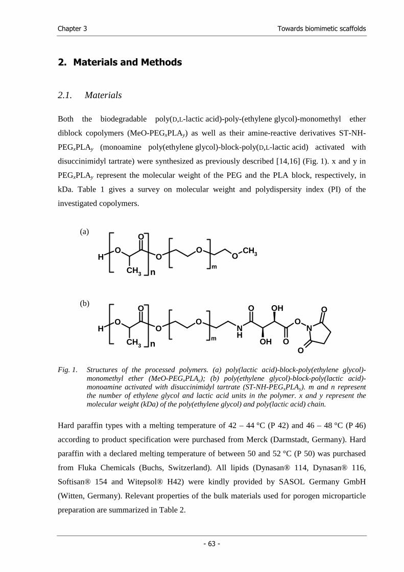
Chapter 3 Towards biomimetic scaffolds
- 63 -
2. Materials and Methods
2.1. Materials
Both the biodegradable poly(D,L-lactic acid)-poly-(ethylene glycol)-monomethyl ether
diblock copolymers (MeO-PEGxPLAy) as well as their amine-reactive derivatives ST-NH-
PEGxPLAy (monoamine poly(ethylene glycol)-block-poly(D,L-lactic acid) activated with
disuccinimidyl tartrate) were synthesized as previously described [14,16] (Fig. 1). x and y in
PEGxPLAy represent the molecular weight of the PEG and the PLA block, respectively, in
kDa. Table 1 gives a survey on molecular weight and polydispersity index (PI) of the
investigated copolymers.
(a)
HO
O
O
O
CH3 n
m
OCH3
(b)
HO
O
O
O
CH3 n
m
NH
ON
O
OH
OH
OO
O
Fig. 1. Structures of the processed polymers. (a) poly(lactic acid)-block-poly(ethylene glycol)-monomethyl ether (MeO-PEGxPLAy); (b) poly(ethylene glycol)-block-poly(lactic acid)-monoamine activated with disuccinimidyl tartrate (ST-NH-PEGxPLAy). m and n represent the number of ethylene glycol and lactic acid units in the polymer. x and y represent the molecular weight (kDa) of the poly(ethylene glycol) and poly(lactic acid) chain.
Hard paraffin types with a melting temperature of 42 – 44 °C (P 42) and 46 – 48 °C (P 46)
according to product specification were purchased from Merck (Darmstadt, Germany). Hard
paraffin with a declared melting temperature of between 50 and 52 °C (P 50) was purchased
from Fluka Chemicals (Buchs, Switzerland). All lipids (Dynasan® 114, Dynasan® 116,
Softisan® 154 and Witepsol® H42) were kindly provided by SASOL Germany GmbH
(Witten, Germany). Relevant properties of the bulk materials used for porogen microparticle
preparation are summarized in Table 2.
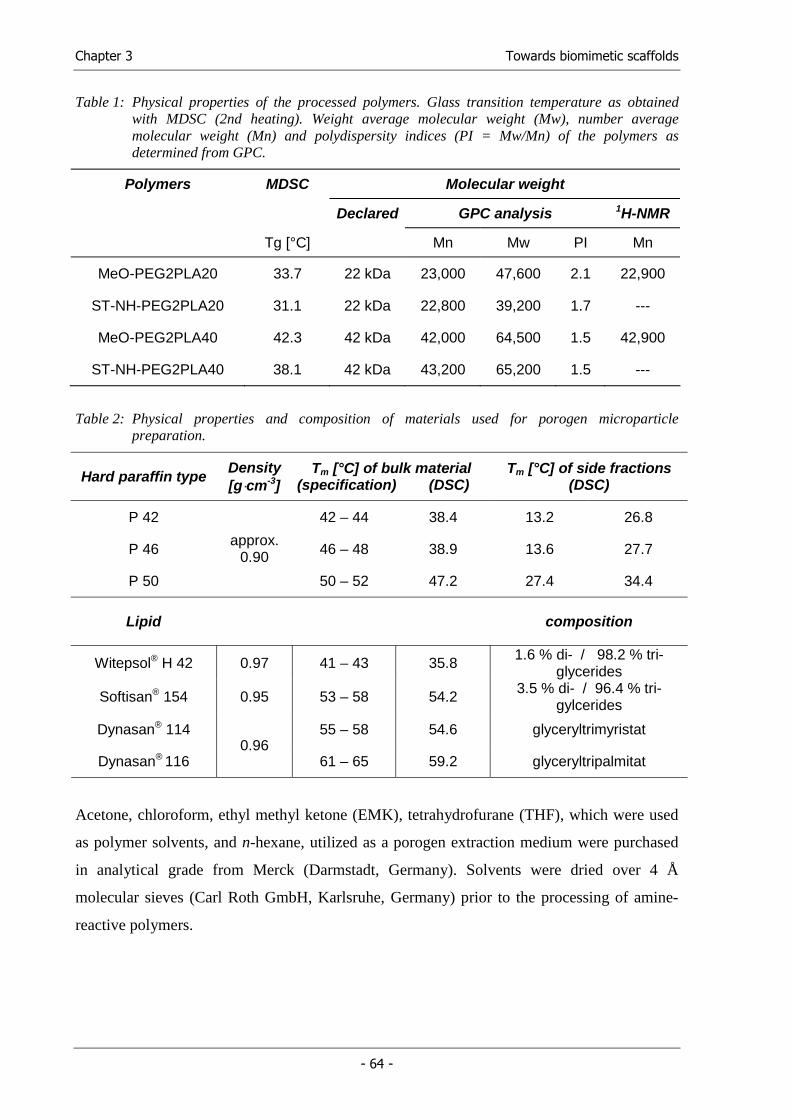
Chapter 3 Towards biomimetic scaffolds
- 64 -
Table 1: Physical properties of the processed polymers. Glass transition temperature as obtained with MDSC (2nd heating). Weight average molecular weight (Mw), number average molecular weight (Mn) and polydispersity indices (PI = Mw/Mn) of the polymers as determined from GPC.
Polymers MDSC Molecular weight
Declared GPC analysis 1H-NMR
Tg [°C] Mn Mw PI Mn
MeO-PEG2PLA20 33.7 22 kDa 23,000 47,600 2.1 22,900
ST-NH-PEG2PLA20 31.1 22 kDa 22,800 39,200 1.7 ---
MeO-PEG2PLA40 42.3 42 kDa 42,000 64,500 1.5 42,900
ST-NH-PEG2PLA40 38.1 42 kDa 43,200 65,200 1.5 ---
Table 2: Physical properties and composition of materials used for porogen microparticle preparation.
Hard paraffin type Density [g⋅cm-3]
Tm [°C] of bulk material (specification) (DSC)
Tm [°C] of side fractions (DSC)
P 42 42 – 44 38.4 13.2 26.8
P 46 46 – 48 38.9 13.6 27.7
P 50
approx. 0.90
50 – 52 47.2 27.4 34.4
Lipid composition
Witepsol® H 42 0.97 41 – 43 35.8 1.6 % di- / 98.2 % tri-glycerides
Softisan® 154 0.95 53 – 58 54.2 3.5 % di- / 96.4 % tri-gylcerides
Dynasan® 114 55 – 58 54.6 glyceryltrimyristat
Dynasan® 116 0.96
61 – 65 59.2 glyceryltripalmitat
Acetone, chloroform, ethyl methyl ketone (EMK), tetrahydrofurane (THF), which were used
as polymer solvents, and n-hexane, utilized as a porogen extraction medium were purchased
in analytical grade from Merck (Darmstadt, Germany). Solvents were dried over 4 Å
molecular sieves (Carl Roth GmbH, Karlsruhe, Germany) prior to the processing of amine-
reactive polymers.
Chapter 3 Towards biomimetic scaffolds
- 65 -
2.2. GPC and 1H-NMR analysis
The molecular weights of the diblock MeO-PEG-PLA copolymers were measured according
to Lucke et al. [14]. The results indicated that both polymers were synthesized in the declared
composition and molecular weight. With regard to the amine-reactive ST-NH-PEG-PLA
copolymers, the composition and molecular weight of the H2N-PEG-PLA precursor were
confirmed with 1H-NMR analysis during synthesis [16]. The declared number average
molecular weights (Mn) of all diblock copolymers correlated well with the values for Mn
obtained by GPC analysis. Furthermore, the polydispersity indices of the polymers indicated
their appropriate molecular weight distribution.
2.3. DSC and MDSC analysis
The glass transition temperatures (Tg) of the polymers were measured utilizing modulated
differential scanning calorimetry (MDSC). This method, which is characteristic for a heating
rate associated with a sinusoidal temperature oscillation, was applied to detect the faint glass
transition step with high resolution and to separate this thermal event from overlapping
relaxation or melting phenomena typical for these diblock copolymers [14]. Generally, Tg of
the diblock copolymers decreased with molecular weight. Tg of the reactive ST-NH-
PEGxPLAy was slightly lower compared with the analog MeO- PEGxPLAy derivative in both
cases.
Differential scanning calorimetry (DSC) was used to determine the melting points of different
hard paraffin types and lipid bulk materials as well as the fabricated porogen microparticles.
Paraffin residuals inside fabricated scaffolds were detected and quantified with DSC analysis,
too. The detection of triglyceride residuals inside the scaffolds, however, was realized through
MDSC.
For calorimetric analysis, all samples were precisely weighed in non-hermetic AutoDSC
aluminum sample pans (TA Instruments, Alzenau, Germany). The sample pans were sealed
using the sample encapsulating press (TA Instruments, Alzenau, Germany) and analyzed on a
DSC 2920 equipped with a refrigerated cooling system and an autosampler (TA Instruments,
Alzenau, Germany). An empty, sealed pan served as reference.
All measurements were carried out between –20 °C and 120 °C. Typically, samples were
equilibrated at –20 °C for 15 min and heated to 120 °C at a heating rate of 2 °C/min (analysis
of porogen materials (DSC) and determination of polymer’s Tg (MDSC)) or 5 °C/min
(determination of residual paraffin (DSC) and triglyceride (MDSC) content). After an
Chapter 3 Towards biomimetic scaffolds
- 66 -
isothermal phase of 15 min, samples were cooled down to –20 °C at the same heating rate.
Finally, after another isothermal phase of 15 min, samples were again heated to 120 °C at the
described heating rate. In case of MDSC measurements, a sinusoidal temperature modulation
with a period of 60 s and a temperature amplitude of 1 °C (determination of polymer’s Tg) or
0.8 °C (determination of residual lipids), was applied to both heating cycles.
The obtained thermograms were analyzed for melting temperature (onset point detection) and
melting enthalpy (peak area) as well as glass transition temperature (obtained as half height of
the transition step) with the Universal Analysis for NT® software provided with the DSC
system.
2.4. Preparation of porogen microparticles
Microparticles were prepared using a melt dispersion technique. The hard paraffin types were
processed by heating a mixture of 10 g hard paraffin with 12.5 ml of a 1.5% (m/v) aqueous
solution of poly(vinyl alcohol) (PVA, 98% hydrolyzed, Aldrich Chemical Company,
Milwaukee, USA) up to 65 °C. The mixture was emulsified by vortex mixing and
subsequently casted into a larger volume (500 ml) of an ice-cooled (5 °C) 0.1% (m/v) aqueous
PVA solution stirred with a propeller stirrer. After 10 min the hardened particles were
collected by filtration, intensively rinsed with water and vacuum dried at room temperature
for 24 hours. Particles or aggregates larger than 710 µm were removed by sieving.
Lipid microparticles were fabricated as described above but without any polymeric surfactant.
The size distribution of the prepared lipid microparticles was investigated using laser
diffraction (Mastersizer 2000 Hydro 2000S, Malvern Instruments, Herrenberg, Germany) as
follows: 100 mg lipid microparticles were suspended in 100 µl 3% (m/v) aqueous HPMC
(Metolose 90 SH 100, Shin-Etsu Co. Ltd., Tokyo, Japan) solution using a vortex mixer. This
suspension was diluted in the dispersion unit (water as dispersant) in accordance with the
obscurity indicator on the instrument and stirred at 3000 µm under sonification (30%
intensity) during the measurement. The volume based particle size distribution was calculated
choosing the Fraunhofer approximation (Malvern Software V5.1).
2.5. Solubility of porogen microparticles
In order to quantify the solubility of the porogen microparticles in the polymer solvent under
processing conditions, 100 mg particles were precisely weighed in glass vials. The vials were
placed in a shaking water bath (frequency: 150 min-1) at a temperature of 0 °C. 5 ml of cold
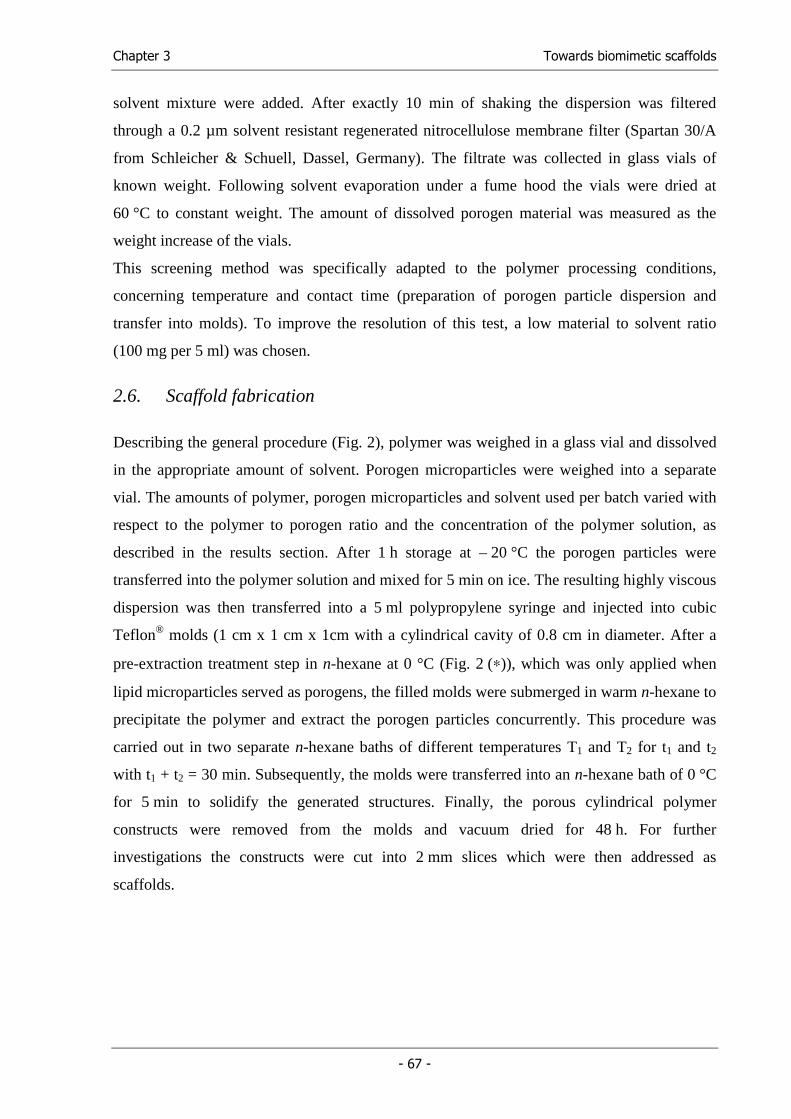
Chapter 3 Towards biomimetic scaffolds
- 67 -
solvent mixture were added. After exactly 10 min of shaking the dispersion was filtered
through a 0.2 µm solvent resistant regenerated nitrocellulose membrane filter (Spartan 30/A
from Schleicher & Schuell, Dassel, Germany). The filtrate was collected in glass vials of
known weight. Following solvent evaporation under a fume hood the vials were dried at
60 °C to constant weight. The amount of dissolved porogen material was measured as the
weight increase of the vials.
This screening method was specifically adapted to the polymer processing conditions,
concerning temperature and contact time (preparation of porogen particle dispersion and
transfer into molds). To improve the resolution of this test, a low material to solvent ratio
(100 mg per 5 ml) was chosen.
2.6. Scaffold fabrication
Describing the general procedure (Fig. 2), polymer was weighed in a glass vial and dissolved
in the appropriate amount of solvent. Porogen microparticles were weighed into a separate
vial. The amounts of polymer, porogen microparticles and solvent used per batch varied with
respect to the polymer to porogen ratio and the concentration of the polymer solution, as
described in the results section. After 1 h storage at – 20 °C the porogen particles were
transferred into the polymer solution and mixed for 5 min on ice. The resulting highly viscous
dispersion was then transferred into a 5 ml polypropylene syringe and injected into cubic
Teflon® molds (1 cm x 1 cm x 1cm with a cylindrical cavity of 0.8 cm in diameter. After a
pre-extraction treatment step in n-hexane at 0 °C (Fig. 2 (∗)), which was only applied when
lipid microparticles served as porogens, the filled molds were submerged in warm n-hexane to
precipitate the polymer and extract the porogen particles concurrently. This procedure was
carried out in two separate n-hexane baths of different temperatures T1 and T2 for t1 and t2
with t1 + t2 = 30 min. Subsequently, the molds were transferred into an n-hexane bath of 0 °C
for 5 min to solidify the generated structures. Finally, the porous cylindrical polymer
constructs were removed from the molds and vacuum dried for 48 h. For further
investigations the constructs were cut into 2 mm slices which were then addressed as
scaffolds.
Chapter 3 Towards biomimetic scaffolds
- 68 -
(∗)(∗)
90 minn-hexane (0°C)
90 minn-hexane (0°C)
porogen extractionn-hexane (warm)
porogen extractionn-hexane (warm)
porous polymercylinder
porous polymercylinder
polymersolventpolymersolvent
polymersolutionpolymersolution
polymerpolymer
+
porogenmicroparticles
porogenmicroparticles dispersiondispersion
Fig. 2: Schematic illustration of the polymer processing procedure. (∗) Pre-extraction treatment of molds in n-hexane at 0°C applied when lipids were used as porogen material.
2.7. Scaffold characterization
The overall structure of the fabricated porous constructs was visualized using a zoom stereo
microscope (Wild M7A, Wild Heerbrugg Ltd., Heerbrugg, Switzerland). For examination of
scaffold microstructure using scanning electron microscopy (SEM), samples were mounted on
aluminum stubs with conductive carbon tape and coated with gold (Fig. 4) or gold –
palladium (Fig. 9). All micrographs were obtained at 10 kV on a JEOL JSM-840 (Jeol Ltd.,
Tokyo, Japan) (Fig. 4) or a DSM 950 (Zeiss, Oberkochen, Germany) (Fig. 9).
Pore size distribution was determined by mercury intrusion porosimetry (AutoPore IV 9500,
Micromeritics, Mönchengladbach, Germany). Scaffolds weighing approximately 25 mg were
sealed in a penetrometer (3 bulb, 0.412 stem, powder; Micromeritics, Mönchengladbach,
Germany) and subjected to analysis. The measurements were performed between 0.0007 and
100 MPa to determine pore-size distributions and porosities. A 30 s equilibration time was set
for each intermediate data point. For data interpretation, a contact angle of 140° and a surface
tension of 0.48 Nm-1 were assumed. These measurements were kindly provided by
Micromeritics.
Chapter 3 Towards biomimetic scaffolds
- 69 -
2.8. Attachment of human insulin to scaffold surfaces
To evaluate the amine reactivity of the scaffold surface, human insulin served as model
protein. In order to provide optimal conditions for the reaction of insulin’s free amine groups
and the activated esters of the polymer, the protein was dissolved (6 mg/ml) in a 0.1M
NaHCO3 buffer at pH = 8.0 with an urea content of 75 mg/ml. Scaffolds were incubated with
2 ml of this insulin solution for 2.5 hours at room temperature on a shaker in a micro test tube
(Eppendorf, Hamburg, Germany). After rinsing with pure buffer and water, the scaffolds were
freeze dried and prepared for GPC analysis: 50 mg of scaffold were dissolved in 400 µl
DMSO. DMSO is a solvent not only for the polymers and the insulin-polymer conjugates, but
also for any free insulin that remained adsorbed to the scaffold even after rinsing. 1600 µl of
chloroform were then added to precipitate free insulin, thus separating adsorbed and
covalently linked insulin. After filtration, 50 µl of the solution were analyzed using GPC
analysis equipped with a RF-551 fluorescence detector (Shimadzu, Duisburg, Germany). The
resulting chromatograms were obtained at λex = 274 nm and λem = 308 nm for the detection of
insulin’s amino acid tyrosine.
Chapter 3 Towards biomimetic scaffolds
- 70 -
3. Results and Discussion
This study was concerned with processing low molecular weight amine-reactive ST-NH-
PEG-PLA and the corresponding non-reactive MeO-PEG-PLA diblock copolymers (42 and
22 kDa (Table 1)) into highly porous and interconnected cell carriers. MeO-PEGxPLAy
diblock copolymers were used to identify the decisive parameters for the processing of PEG-
PLA diblock copolymers, which were then correlated to polymer’s molecular weight and
glass transition temperature (Tg) and finally adapted to the special properties of the amine-
reactive derivatives.
A recently published hydrocarbon templating method [27,29] met our demands for
anhydrous processing, for an interconnected pore structure, and for pore size control. This
method involved preparation of a dispersion of paraffin microparticles in a polymer solution.
This dispersion was transferred into a Teflon® mold and placed into warm n-hexane, a solvent
for the porogen to achieve particulate leaching while being a poor solvent for the polymer.
Thus, on contact with this solvent, the polymer precipitated on the extracted porogen particles
leading to an interconnected scaffold architecture [27]. However, up to now only
biodegradable polymers with a molecular weight of above 70 kDa had been processed and a
limit of 40 kDa had been assumed by the authors. In order to develop a new processing
method for low molecular weight diblock copolymers based on the hydrocarbon templating
technique, it was necessary to investigate the limitations of this technique.
Three problems soon became obvious in preliminary investigations; firstly, the published
extraction temperature of 45 - 50 °C over 20 min [29] or even 50 °C over 40 min [30] were
incompatible with the low glass transition temperature (Tg) of the diblock copolymer
investigated in this study and led a collapse of the constructs during processing. A survey of
these polymers including their determined Tg and molecular weights, is given in Table 1.
Secondly, lowering the extraction temperature made the commonly used high melting paraffin
(Tm = 53 – 57 °C) [28] unsuitable as a porogen material due to insufficient extraction.
Thirdly, lower melting hard paraffin was soluble in the published polymer solvent
chloroform. Consequently, we varied each of the three parameters: the porogen material, the
polymer solvent and the extraction conditions.
Chapter 3 Towards biomimetic scaffolds
- 71 -
3.1. Scaffold fabrication using paraffin microparticles as porogens
3.1.1. Porogen material: Characterization of paraffin microparticles
Microparticles were prepared from three low melting hard paraffin types with declared
melting points of 42 – 44 °C (P 42), 46 – 48 °C (P 46) and 50 – 52 °C (P 50), respectively.
Although these paraffin types apparently offered a considerable range of melting points, the
fabricated particles formed cohesive powders not allowing for the preparation of a
homogeneous dispersion of these particles in a polymer solution, especially in case of the hard
paraffin types P 42 and P 46. DSC analysis of bulk and processed hard paraffin clarified this
behavior: instead of one endothermic melting peak, the thermograms revealed three peaks
representing different hydrocarbon fractions (Table 2). Moreover, the predominant side
fraction in each of the three investigated hard paraffin types melted at least 20 °C below the
main hydrocarbon fraction. These low melting fractions were probably responsible for
microparticle agglomeration. In consequence, only P 50 particles were suitable as porogen
material for further experiments.
3.1.2. Polymer solvent
Methylene chloride or chloroform have been described as suitable polymer solvents [29].
Preliminary tests revealed that all three described hard paraffin types were soluble in these
solvents to a considerable extent. Acetone, a non-solvent for the hard paraffin, would have
been a suitable polymer solvent, but was excluded in early experiments due to its low boiling
point, which disturbed the scaffold formation by forming gas bubbles during porogen
extraction. To overcome these problems, we chose an azeotropic mixture of 65% (v/v)
acetone and 35% (v/v) chloroform with a boiling point of 65°C as polymer solvent [31]. Since
the azeotrope’s boiling point was well above the ones of both single components, the addition
of acetone did not limit the applicable extraction conditions.
Solubility tests of the porogen microparticles made of the three investigated hard paraffin
types revealed that microparticle solubility increased with decreasing melting temperature
(Fig. 3). The solubility of P 50 and P 46 microparticles was below 10 mg in 5 ml of the
acetone - chloroform mixture. Less than 15 mg of P 42 were dissolved in 5 ml solvent
mixture. Thus, the solubility of all three paraffin types was considered as being sufficiently
low, however, due to the thermal characteristics described above, only P 50 was suitable as
porogen material.
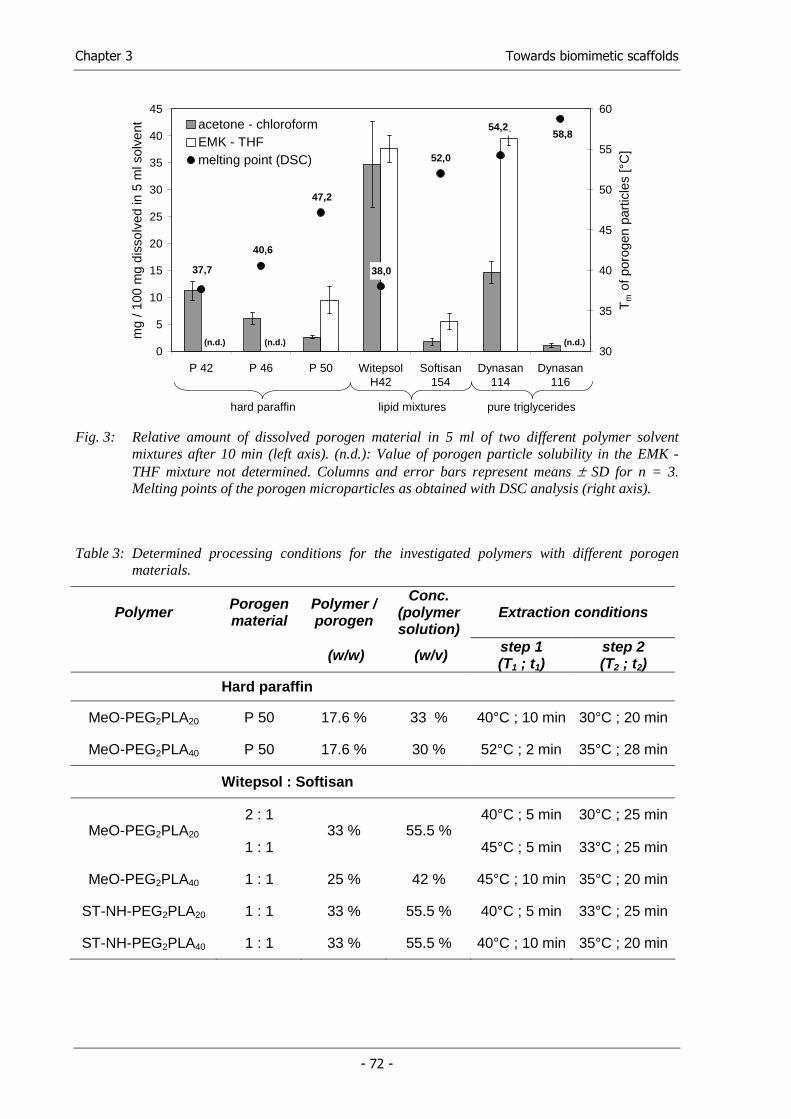
Chapter 3 Towards biomimetic scaffolds
- 72 -
58,8
52,0
47,2
40,6
37,7
54,2
38,0
0
5
10
15
20
25
30
35
40
45
P 42 P 46 P 50 WitepsolH42
Softisan154
Dynasan114
Dynasan116
mg
/ 100
mg
diss
olve
d in
5 m
l sol
vent
30
35
40
45
50
55
60
Tm
of p
orog
en p
artic
les
[°C
]
acetone - chloroformEMK - THFmelting point (DSC)
hard paraffin lipid mixtures pure triglycerides
(n.d.) (n.d.) (n.d.)
Fig. 3: Relative amount of dissolved porogen material in 5 ml of two different polymer solvent
mixtures after 10 min (left axis). (n.d.): Value of porogen particle solubility in the EMK - THF mixture not determined. Columns and error bars represent means ± SD for n = 3. Melting points of the porogen microparticles as obtained with DSC analysis (right axis).
Table 3: Determined processing conditions for the investigated polymers with different porogen materials.
Polymer Porogen material
Polymer / porogen
Conc. (polymer solution)
Extraction conditions
(w/w) (w/v) step 1 (T1 ; t1)
step 2 (T2 ; t2)
Hard paraffin
MeO-PEG2PLA20 P 50 17.6 % 33 % 40°C ; 10 min 30°C ; 20 min
MeO-PEG2PLA40 P 50 17.6 % 30 % 52°C ; 2 min 35°C ; 28 min
Witepsol : Softisan
2 : 1 40°C ; 5 min 30°C ; 25 min MeO-PEG2PLA20
1 : 1 33 % 55.5 %
45°C ; 5 min 33°C ; 25 min
MeO-PEG2PLA40 1 : 1 25 % 42 % 45°C ; 10 min 35°C ; 20 min
ST-NH-PEG2PLA20 1 : 1 33 % 55.5 % 40°C ; 5 min 33°C ; 25 min
ST-NH-PEG2PLA40 1 : 1 33 % 55.5 % 40°C ; 10 min 35°C ; 20 min
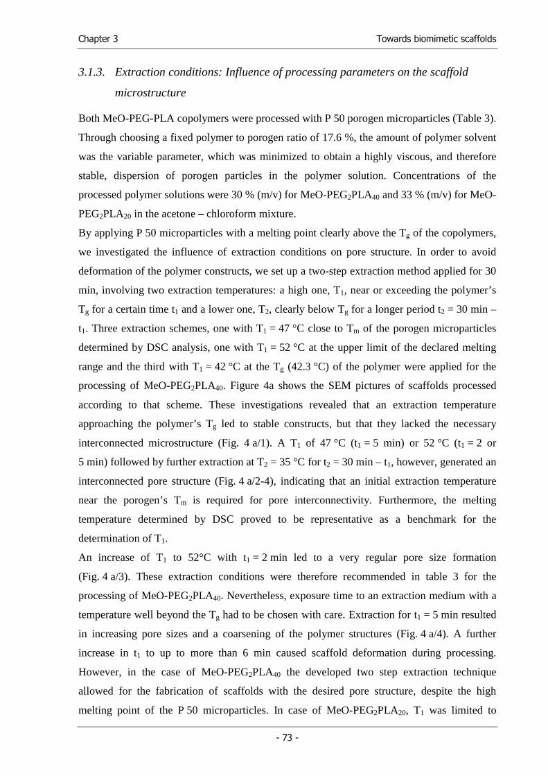
Chapter 3 Towards biomimetic scaffolds
- 73 -
3.1.3. Extraction conditions: Influence of processing parameters on the scaffold
microstructure
Both MeO-PEG-PLA copolymers were processed with P 50 porogen microparticles (Table 3).
Through choosing a fixed polymer to porogen ratio of 17.6 %, the amount of polymer solvent
was the variable parameter, which was minimized to obtain a highly viscous, and therefore
stable, dispersion of porogen particles in the polymer solution. Concentrations of the
processed polymer solutions were 30 % (m/v) for MeO-PEG2PLA40 and 33 % (m/v) for MeO-
PEG2PLA20 in the acetone – chloroform mixture.
By applying P 50 microparticles with a melting point clearly above the Tg of the copolymers,
we investigated the influence of extraction conditions on pore structure. In order to avoid
deformation of the polymer constructs, we set up a two-step extraction method applied for 30
min, involving two extraction temperatures: a high one, T1, near or exceeding the polymer’s
Tg for a certain time t1 and a lower one, T2, clearly below Tg for a longer period t2 = 30 min –
t1. Three extraction schemes, one with T1 = 47 °C close to Tm of the porogen microparticles
determined by DSC analysis, one with T1 = 52 °C at the upper limit of the declared melting
range and the third with T1 = 42 °C at the Tg (42.3 °C) of the polymer were applied for the
processing of MeO-PEG2PLA40. Figure 4a shows the SEM pictures of scaffolds processed
according to that scheme. These investigations revealed that an extraction temperature
approaching the polymer’s Tg led to stable constructs, but that they lacked the necessary
interconnected microstructure (Fig. 4 a/1). A T1 of 47 °C (t1 = 5 min) or 52 °C (t1 = 2 or
5 min) followed by further extraction at T2 = 35 °C for t2 = 30 min – t1, however, generated an
interconnected pore structure (Fig. 4 a/2-4), indicating that an initial extraction temperature
near the porogen’s Tm is required for pore interconnectivity. Furthermore, the melting
temperature determined by DSC proved to be representative as a benchmark for the
determination of T1.
An increase of T1 to 52°C with t1 = 2 min led to a very regular pore size formation
(Fig. 4 a/3). These extraction conditions were therefore recommended in table 3 for the
processing of MeO-PEG2PLA40. Nevertheless, exposure time to an extraction medium with a
temperature well beyond the Tg had to be chosen with care. Extraction for t1 = 5 min resulted
in increasing pore sizes and a coarsening of the polymer structures (Fig. 4 a/4). A further
increase in t1 to up to more than 6 min caused scaffold deformation during processing.
However, in the case of MeO-PEG2PLA40 the developed two step extraction technique
allowed for the fabrication of scaffolds with the desired pore structure, despite the high
melting point of the P 50 microparticles. In case of MeO-PEG2PLA20, T1 was limited to
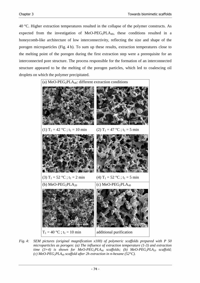
Chapter 3 Towards biomimetic scaffolds
- 74 -
40 °C. Higher extraction temperatures resulted in the collapse of the polymer constructs. As
expected from the investigation of MeO-PEG2PLA40, these conditions resulted in a
honeycomb-like architecture of low interconnectivity, reflecting the size and shape of the
porogen microparticles (Fig. 4 b). To sum up these results, extraction temperatures close to
the melting point of the porogen during the first extraction step were a prerequisite for an
interconnected pore structure. The process responsible for the formation of an interconnected
structure appeared to be the melting of the porogen particles, which led to coalescing oil
droplets on which the polymer precipitated.
(a) MeO-PEG2PLA40: different extraction conditions
(1) T1 = 42 °C ; t1 = 10 min (2) T1 = 47 °C ; t1 = 5 min
(3) T1 = 52 °C ; t1 = 2 min (4) T1 = 52 °C ; t1 = 5 min
(b) MeO-PEG2PLA20 (c) MeO-PEG2PLA40
T1 = 40 °C ; t1 = 10 min additional purification
Fig. 4: SEM pictures (original magnification x100) of polymeric scaffolds prepared with P 50 microparticles as porogen: (a) The influence of extraction temperature (1-3) and extraction time (3+4) is shown for MeO-PEG2PLA40 scaffolds; (b) MeO-PEG2PLA20 scaffold; (c) MeO-PEG2PLA40 scaffold after 2h extraction in n-hexane (52°C).
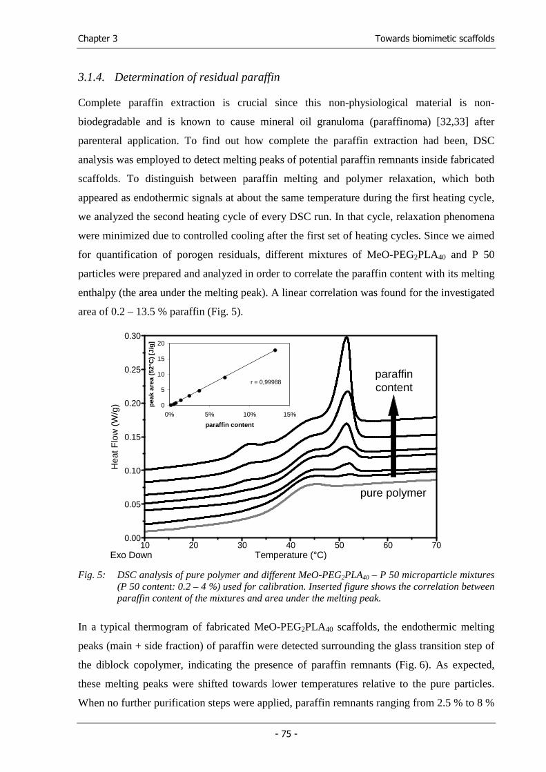
Chapter 3 Towards biomimetic scaffolds
- 75 -
3.1.4. Determination of residual paraffin
Complete paraffin extraction is crucial since this non-physiological material is non-
biodegradable and is known to cause mineral oil granuloma (paraffinoma) [32,33] after
parenteral application. To find out how complete the paraffin extraction had been, DSC
analysis was employed to detect melting peaks of potential paraffin remnants inside fabricated
scaffolds. To distinguish between paraffin melting and polymer relaxation, which both
appeared as endothermic signals at about the same temperature during the first heating cycle,
we analyzed the second heating cycle of every DSC run. In that cycle, relaxation phenomena
were minimized due to controlled cooling after the first set of heating cycles. Since we aimed
for quantification of porogen residuals, different mixtures of MeO-PEG2PLA40 and P 50
particles were prepared and analyzed in order to correlate the paraffin content with its melting
enthalpy (the area under the melting peak). A linear correlation was found for the investigated
area of 0.2 – 13.5 % paraffin (Fig. 5).
0.00
0.05
0.10
0.15
0.20
0.25
0.30
10 20 30 40 50 60 70Temperature (°C)Exo Down
paraffincontent
pure polymer
Hea
tFlo
w(W
/g) 0
5
10
15
20
0% 5% 10% 15%
paraffin content
pea
k ar
ea (
52°C
) [J
/g]
r = 0,99988
Hea
tFlo
w(W
/g)
Fig. 5: DSC analysis of pure polymer and different MeO-PEG2PLA40 – P 50 microparticle mixtures
(P 50 content: 0.2 – 4 %) used for calibration. Inserted figure shows the correlation between paraffin content of the mixtures and area under the melting peak.
In a typical thermogram of fabricated MeO-PEG2PLA40 scaffolds, the endothermic melting
peaks (main + side fraction) of paraffin were detected surrounding the glass transition step of
the diblock copolymer, indicating the presence of paraffin remnants (Fig. 6). As expected,
these melting peaks were shifted towards lower temperatures relative to the pure particles.
When no further purification steps were applied, paraffin remnants ranging from 2.5 % to 8 %
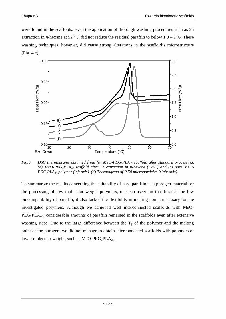
Chapter 3 Towards biomimetic scaffolds
- 76 -
were found in the scaffolds. Even the application of thorough washing procedures such as 2h
extraction in n-hexane at 52 °C, did not reduce the residual paraffin to below 1.8 – 2 %. These
washing techniques, however, did cause strong alterations in the scaffold’s microstructure
(Fig. 4 c).
0.0
0.5
1.0
1.5
2.0
2.5
3.0
0.10
0.15
0.20
0.25
0.30
10 20 30 40 50 60 70Temperature (°C)Exo Down
Hea
tFlo
w(W
/g)
Hea
tFlo
w(W
/g)
a)b)c)
d)
Fig.6: DSC thermograms obtained from (b) MeO-PEG2PLA40 scaffold after standard processing, (a) MeO-PEG2PLA40 scaffold after 2h extraction in n-hexane (52°C) and (c) pure MeO-PEG2PLA40 polymer (left axis). (d) Thermogram of P 50 microparticles (right axis).
To summarize the results concerning the suitability of hard paraffin as a porogen material for
the processing of low molecular weight polymers, one can ascertain that besides the low
biocompatibility of paraffin, it also lacked the flexibility in melting points necessary for the
investigated polymers. Although we achieved well interconnected scaffolds with MeO-
PEG2PLA40, considerable amounts of paraffin remained in the scaffolds even after extensive
washing steps. Due to the large difference between the Tg of the polymer and the melting
point of the porogen, we did not manage to obtain interconnected scaffolds with polymers of
lower molecular weight, such as MeO-PEG2PLA20.
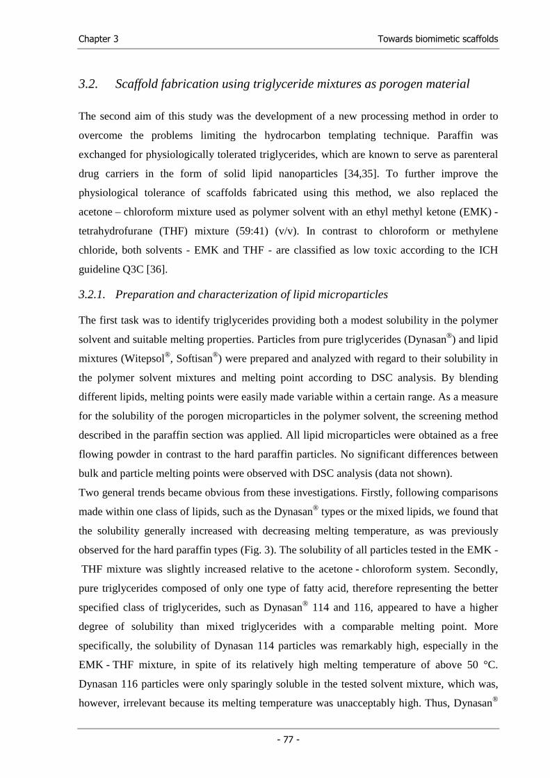
Chapter 3 Towards biomimetic scaffolds
- 77 -
3.2. Scaffold fabrication using triglyceride mixtures as porogen material
The second aim of this study was the development of a new processing method in order to
overcome the problems limiting the hydrocarbon templating technique. Paraffin was
exchanged for physiologically tolerated triglycerides, which are known to serve as parenteral
drug carriers in the form of solid lipid nanoparticles [34,35]. To further improve the
physiological tolerance of scaffolds fabricated using this method, we also replaced the
acetone – chloroform mixture used as polymer solvent with an ethyl methyl ketone (EMK) -
tetrahydrofurane (THF) mixture (59:41) (v/v). In contrast to chloroform or methylene
chloride, both solvents - EMK and THF - are classified as low toxic according to the ICH
guideline Q3C [36].
3.2.1. Preparation and characterization of lipid microparticles
The first task was to identify triglycerides providing both a modest solubility in the polymer
solvent and suitable melting properties. Particles from pure triglycerides (Dynasan®) and lipid
mixtures (Witepsol®, Softisan®) were prepared and analyzed with regard to their solubility in
the polymer solvent mixtures and melting point according to DSC analysis. By blending
different lipids, melting points were easily made variable within a certain range. As a measure
for the solubility of the porogen microparticles in the polymer solvent, the screening method
described in the paraffin section was applied. All lipid microparticles were obtained as a free
flowing powder in contrast to the hard paraffin particles. No significant differences between
bulk and particle melting points were observed with DSC analysis (data not shown).
Two general trends became obvious from these investigations. Firstly, following comparisons
made within one class of lipids, such as the Dynasan® types or the mixed lipids, we found that
the solubility generally increased with decreasing melting temperature, as was previously
observed for the hard paraffin types (Fig. 3). The solubility of all particles tested in the EMK -
THF mixture was slightly increased relative to the acetone - chloroform system. Secondly,
pure triglycerides composed of only one type of fatty acid, therefore representing the better
specified class of triglycerides, such as Dynasan® 114 and 116, appeared to have a higher
degree of solubility than mixed triglycerides with a comparable melting point. More
specifically, the solubility of Dynasan 114 particles was remarkably high, especially in the
EMK - THF mixture, in spite of its relatively high melting temperature of above 50 °C.
Dynasan 116 particles were only sparingly soluble in the tested solvent mixture, which was,
however, irrelevant because its melting temperature was unacceptably high. Thus, Dynasan®
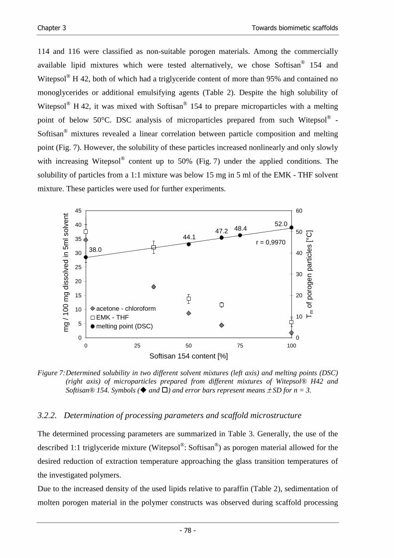
Chapter 3 Towards biomimetic scaffolds
- 78 -
114 and 116 were classified as non-suitable porogen materials. Among the commercially
available lipid mixtures which were tested alternatively, we chose Softisan® 154 and
Witepsol® H 42, both of which had a triglyceride content of more than 95% and contained no
monoglycerides or additional emulsifying agents (Table 2). Despite the high solubility of
Witepsol® H 42, it was mixed with Softisan® 154 to prepare microparticles with a melting
point of below 50°C. DSC analysis of microparticles prepared from such Witepsol® -
Softisan® mixtures revealed a linear correlation between particle composition and melting
point (Fig. 7). However, the solubility of these particles increased nonlinearly and only slowly
with increasing Witepsol® content up to 50% (Fig. 7) under the applied conditions. The
solubility of particles from a 1:1 mixture was below 15 mg in 5 ml of the EMK - THF solvent
mixture. These particles were used for further experiments.
0
5
10
15
20
25
30
35
40
45
0 25 50 75 100
Softisan 154 content [%]
0
10
20
30
40
50
60
Tm o
f por
ogen
par
ticle
s [°
C]
acetone - chloroformEMK - THFmelting point (DSC)
38.0
44.147.2
52.048.4
r = 0,9970
mg
/ 100
mg
diss
olve
d in
5m
l sol
vent
Figure 7: Determined solubility in two different solvent mixtures (left axis) and melting points (DSC)
(right axis) of microparticles prepared from different mixtures of Witepsol® H42 and Softisan® 154. Symbols ( and ) and error bars represent means ± SD for n = 3.
3.2.2. Determination of processing parameters and scaffold microstructure
The determined processing parameters are summarized in Table 3. Generally, the use of the
described 1:1 triglyceride mixture (Witepsol®: Softisan®) as porogen material allowed for the
desired reduction of extraction temperature approaching the glass transition temperatures of
the investigated polymers.
Due to the increased density of the used lipids relative to paraffin (Table 2), sedimentation of
molten porogen material in the polymer constructs was observed during scaffold processing
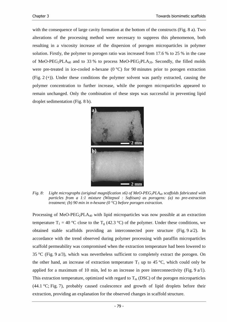
Chapter 3 Towards biomimetic scaffolds
- 79 -
with the consequence of large cavity formation at the bottom of the constructs (Fig. 8 a). Two
alterations of the processing method were necessary to suppress this phenomenon, both
resulting in a viscosity increase of the dispersion of porogen microparticles in polymer
solution. Firstly, the polymer to porogen ratio was increased from 17.6 % to 25 % in the case
of MeO-PEG2PLA40 and to 33 % to process MeO-PEG2PLA20. Secondly, the filled molds
were pre-treated in ice-cooled n-hexane (0 °C) for 90 minutes prior to porogen extraction
(Fig. 2 (∗)). Under these conditions the polymer solvent was partly extracted, causing the
polymer concentration to further increase, while the porogen microparticles appeared to
remain unchanged. Only the combination of these steps was successful in preventing lipid
droplet sedimentation (Fig. 8 b).
a)
2 mm
a)
2 mm
2 mm
b)
2 mm
b)
Fig. 8: Light micrographs (original magnification x6) of MeO-PEG2PLA40 scaffolds fabricated with
particles from a 1:1 mixture (Witepsol : Softisan) as porogens: (a) no pre-extraction treatment; (b) 90 min in n-hexane (0 °C) before porogen extraction.
Processing of MeO-PEG2PLA40 with lipid microparticles was now possible at an extraction
temperature T1 = 40 °C close to the Tg (42.3 °C) of the polymer. Under these conditions, we
obtained stable scaffolds providing an interconnected pore structure (Fig. 9 a/2). In
accordance with the trend observed during polymer processing with paraffin microparticles
scaffold permeability was compromised when the extraction temperature had been lowered to
35 °C (Fig. 9 a/3), which was nevertheless sufficient to completely extract the porogen. On
the other hand, an increase of extraction temperature T1 up to 45 °C, which could only be
applied for a maximum of 10 min, led to an increase in pore interconnectivity (Fig. 9 a/1).
This extraction temperature, optimized with regard to Tm (DSC) of the porogen microparticles
(44.1 °C; Fig. 7), probably caused coalescence and growth of lipid droplets before their
extraction, providing an explanation for the observed changes in scaffold structure.
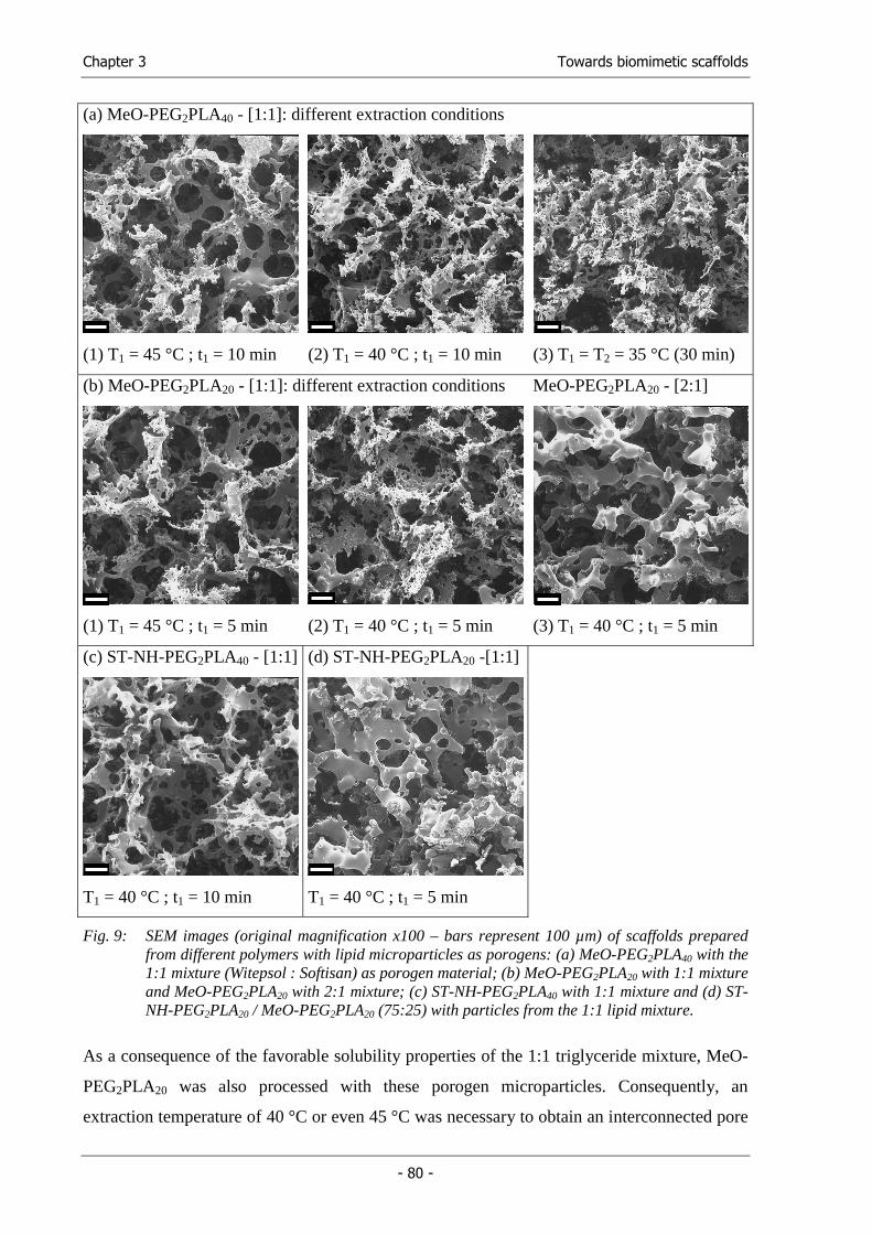
Chapter 3 Towards biomimetic scaffolds
- 80 -
(a) MeO-PEG2PLA40 - [1:1]: different extraction conditions
(1) T1 = 45 °C ; t1 = 10 min (2) T1 = 40 °C ; t1 = 10 min (3) T1 = T2 = 35 °C (30 min)
(b) MeO-PEG2PLA20 - [1:1]: different extraction conditions MeO-PEG2PLA20 - [2:1]
(1) T1 = 45 °C ; t1 = 5 min (2) T1 = 40 °C ; t1 = 5 min (3) T1 = 40 °C ; t1 = 5 min
(c) ST-NH-PEG2PLA40 - [1:1] (d) ST-NH-PEG2PLA20 -[1:1]
T1 = 40 °C ; t1 = 10 min T1 = 40 °C ; t1 = 5 min
Fig. 9: SEM images (original magnification x100 – bars represent 100 µm) of scaffolds prepared from different polymers with lipid microparticles as porogens: (a) MeO-PEG2PLA40 with the 1:1 mixture (Witepsol : Softisan) as porogen material; (b) MeO-PEG2PLA20 with 1:1 mixture and MeO-PEG2PLA20 with 2:1 mixture; (c) ST-NH-PEG2PLA40 with 1:1 mixture and (d) ST-NH-PEG2PLA20 / MeO-PEG2PLA20 (75:25) with particles from the 1:1 lipid mixture.
As a consequence of the favorable solubility properties of the 1:1 triglyceride mixture, MeO-
PEG2PLA20 was also processed with these porogen microparticles. Consequently, an
extraction temperature of 40 °C or even 45 °C was necessary to obtain an interconnected pore
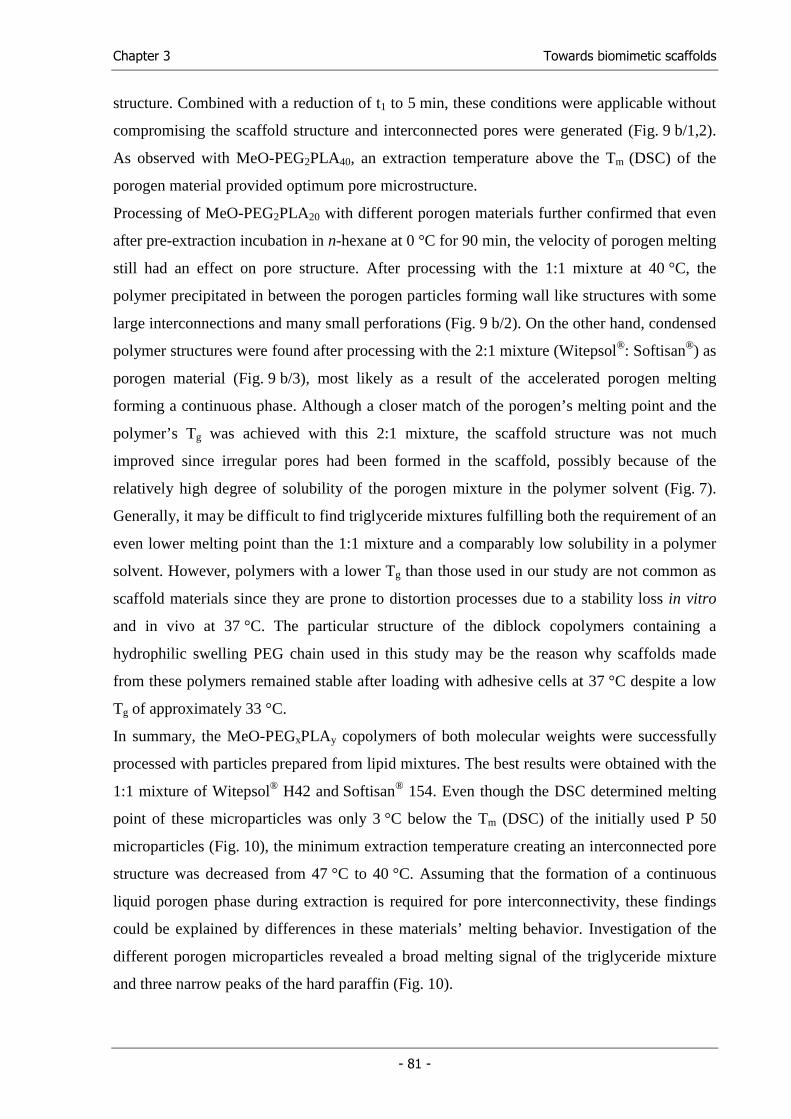
Chapter 3 Towards biomimetic scaffolds
- 81 -
structure. Combined with a reduction of t1 to 5 min, these conditions were applicable without
compromising the scaffold structure and interconnected pores were generated (Fig. 9 b/1,2).
As observed with MeO-PEG2PLA40, an extraction temperature above the Tm (DSC) of the
porogen material provided optimum pore microstructure.
Processing of MeO-PEG2PLA20 with different porogen materials further confirmed that even
after pre-extraction incubation in n-hexane at 0 °C for 90 min, the velocity of porogen melting
still had an effect on pore structure. After processing with the 1:1 mixture at 40 °C, the
polymer precipitated in between the porogen particles forming wall like structures with some
large interconnections and many small perforations (Fig. 9 b/2). On the other hand, condensed
polymer structures were found after processing with the 2:1 mixture (Witepsol®: Softisan®) as
porogen material (Fig. 9 b/3), most likely as a result of the accelerated porogen melting
forming a continuous phase. Although a closer match of the porogen’s melting point and the
polymer’s Tg was achieved with this 2:1 mixture, the scaffold structure was not much
improved since irregular pores had been formed in the scaffold, possibly because of the
relatively high degree of solubility of the porogen mixture in the polymer solvent (Fig. 7).
Generally, it may be difficult to find triglyceride mixtures fulfilling both the requirement of an
even lower melting point than the 1:1 mixture and a comparably low solubility in a polymer
solvent. However, polymers with a lower Tg than those used in our study are not common as
scaffold materials since they are prone to distortion processes due to a stability loss in vitro
and in vivo at 37 °C. The particular structure of the diblock copolymers containing a
hydrophilic swelling PEG chain used in this study may be the reason why scaffolds made
from these polymers remained stable after loading with adhesive cells at 37 °C despite a low
Tg of approximately 33 °C.
In summary, the MeO-PEGxPLAy copolymers of both molecular weights were successfully
processed with particles prepared from lipid mixtures. The best results were obtained with the
1:1 mixture of Witepsol® H42 and Softisan® 154. Even though the DSC determined melting
point of these microparticles was only 3 °C below the Tm (DSC) of the initially used P 50
microparticles (Fig. 10), the minimum extraction temperature creating an interconnected pore
structure was decreased from 47 °C to 40 °C. Assuming that the formation of a continuous
liquid porogen phase during extraction is required for pore interconnectivity, these findings
could be explained by differences in these materials’ melting behavior. Investigation of the
different porogen microparticles revealed a broad melting signal of the triglyceride mixture
and three narrow peaks of the hard paraffin (Fig. 10).
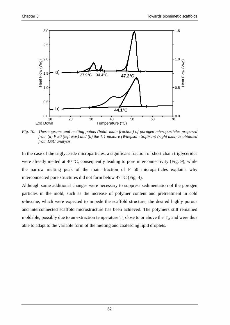
Chapter 3 Towards biomimetic scaffolds
- 82 -
0.0
0.5
1.0
1.5
0.0
0.5
1.0
1.5
2.0
2.5
3.0
10 20 30 40 50 60 70Temperature (°C)Exo Down
Hea
tFlo
w(W
/g)
b)
34.4°C27.9°C 47.2°C
44.1°C
Hea
tFlo
w(W
/g)
a)
Fig. 10: Thermograms and melting points (bold: main fraction) of porogen microparticles prepared
from (a) P 50 (left axis) and (b) the 1:1 mixture (Witepsol : Softisan) (right axis) as obtained from DSC analysis.
In the case of the triglyceride microparticles, a significant fraction of short chain triglycerides
were already melted at 40 °C, consequently leading to pore interconnectivity (Fig. 9), while
the narrow melting peak of the main fraction of P 50 microparticles explains why
interconnected pore structures did not form below 47 °C (Fig. 4).
Although some additional changes were necessary to suppress sedimentation of the porogen
particles in the mold, such as the increase of polymer content and pretreatment in cold
n-hexane, which were expected to impede the scaffold structure, the desired highly porous
and interconnected scaffold microstructure has been achieved. The polymers still remained
moldable, possibly due to an extraction temperature T1 close to or above the Tg, and were thus
able to adapt to the variable form of the melting and coalescing lipid droplets.
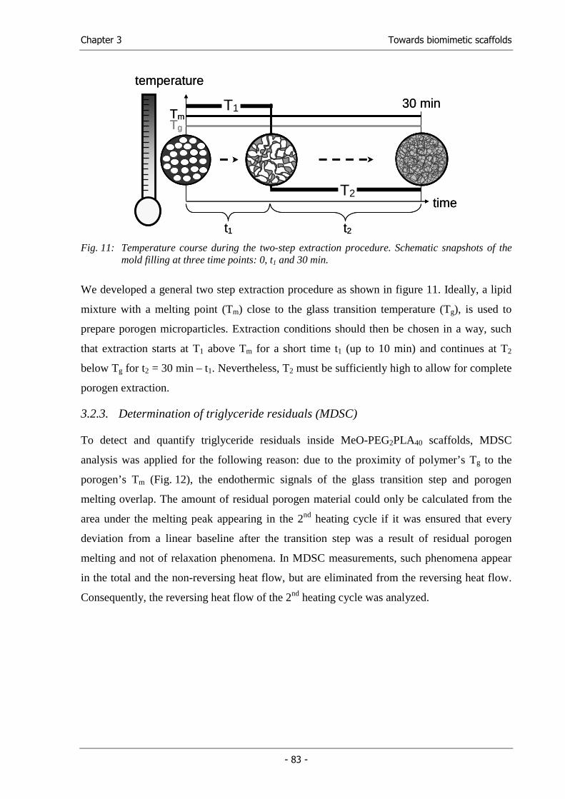
Chapter 3 Towards biomimetic scaffolds
- 83 -
TmTg
t1 t2
30 minT1
T2time
temperature
TmTg
t1 t2
30 minT1
T2time
temperature
Fig. 11: Temperature course during the two-step extraction procedure. Schematic snapshots of the
mold filling at three time points: 0, t1 and 30 min.
We developed a general two step extraction procedure as shown in figure 11. Ideally, a lipid
mixture with a melting point (Tm) close to the glass transition temperature (Tg), is used to
prepare porogen microparticles. Extraction conditions should then be chosen in a way, such
that extraction starts at T1 above Tm for a short time t1 (up to 10 min) and continues at T2
below Tg for t2 = 30 min – t1. Nevertheless, T2 must be sufficiently high to allow for complete
porogen extraction.
3.2.3. Determination of triglyceride residuals (MDSC)
To detect and quantify triglyceride residuals inside MeO-PEG2PLA40 scaffolds, MDSC
analysis was applied for the following reason: due to the proximity of polymer’s Tg to the
porogen’s Tm (Fig. 12), the endothermic signals of the glass transition step and porogen
melting overlap. The amount of residual porogen material could only be calculated from the
area under the melting peak appearing in the 2nd heating cycle if it was ensured that every
deviation from a linear baseline after the transition step was a result of residual porogen
melting and not of relaxation phenomena. In MDSC measurements, such phenomena appear
in the total and the non-reversing heat flow, but are eliminated from the reversing heat flow.
Consequently, the reversing heat flow of the 2nd heating cycle was analyzed.
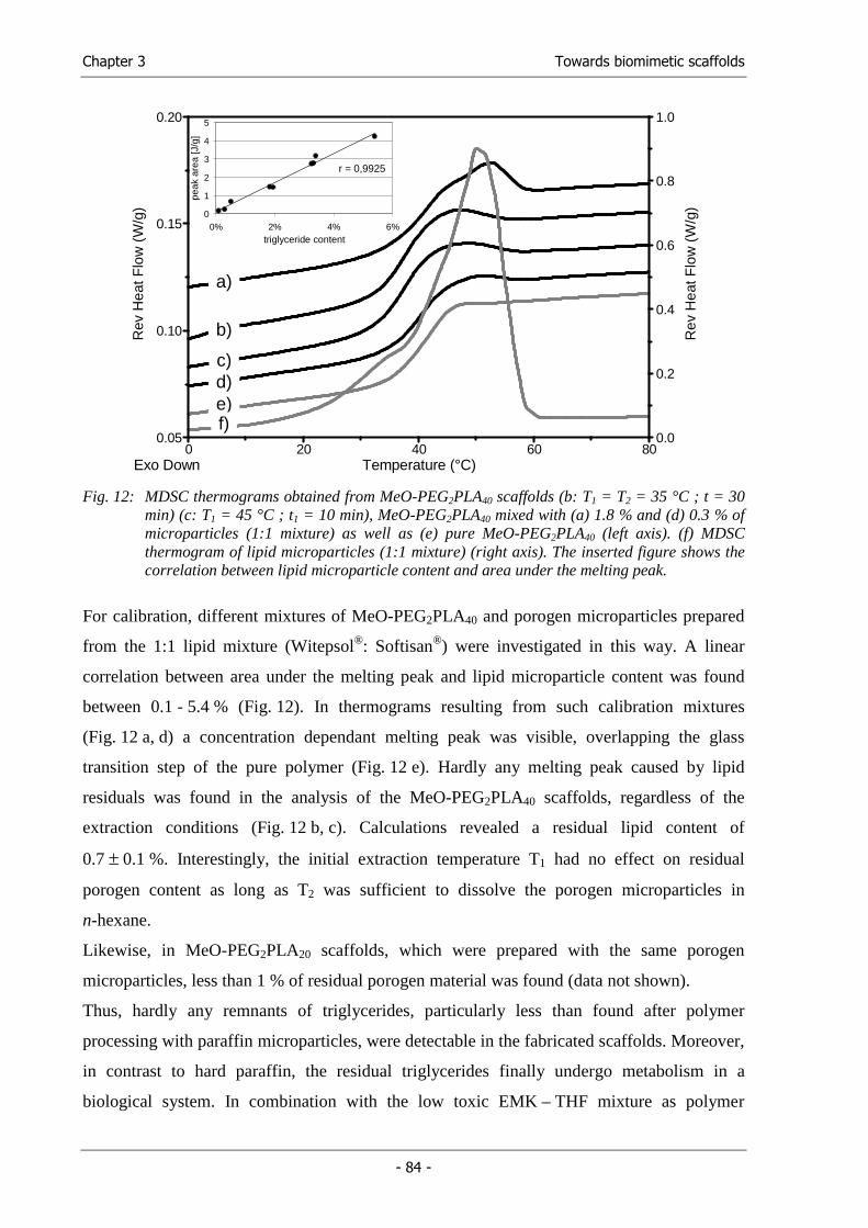
Chapter 3 Towards biomimetic scaffolds
- 84 -
0.0
0.2
0.4
0.6
0.8
1.0
0.05
0.10
0.15
0.20
0 20 40 60 80Temperature (°C)Exo Down
Rev
Hea
tFlo
w(W
/g)
Rev
Hea
tFlo
w(W
/g)
b)
d)e)f)
c)
a)
0
1
2
3
4
5
0% 2% 4% 6%triglyceride content
peak
are
a [J
/g]
r = 0,9925
Fig. 12: MDSC thermograms obtained from MeO-PEG2PLA40 scaffolds (b: T1 = T2 = 35 °C ; t = 30
min) (c: T1 = 45 °C ; t1 = 10 min), MeO-PEG2PLA40 mixed with (a) 1.8 % and (d) 0.3 % of microparticles (1:1 mixture) as well as (e) pure MeO-PEG2PLA40 (left axis). (f) MDSC thermogram of lipid microparticles (1:1 mixture) (right axis). The inserted figure shows the correlation between lipid microparticle content and area under the melting peak.
For calibration, different mixtures of MeO-PEG2PLA40 and porogen microparticles prepared
from the 1:1 lipid mixture (Witepsol®: Softisan®) were investigated in this way. A linear
correlation between area under the melting peak and lipid microparticle content was found
between 0.1 - 5.4 % (Fig. 12). In thermograms resulting from such calibration mixtures
(Fig. 12 a, d) a concentration dependant melting peak was visible, overlapping the glass
transition step of the pure polymer (Fig. 12 e). Hardly any melting peak caused by lipid
residuals was found in the analysis of the MeO-PEG2PLA40 scaffolds, regardless of the
extraction conditions (Fig. 12 b, c). Calculations revealed a residual lipid content of
0.7 ± 0.1 %. Interestingly, the initial extraction temperature T1 had no effect on residual
porogen content as long as T2 was sufficient to dissolve the porogen microparticles in
n-hexane.
Likewise, in MeO-PEG2PLA20 scaffolds, which were prepared with the same porogen
microparticles, less than 1 % of residual porogen material was found (data not shown).
Thus, hardly any remnants of triglycerides, particularly less than found after polymer
processing with paraffin microparticles, were detectable in the fabricated scaffolds. Moreover,
in contrast to hard paraffin, the residual triglycerides finally undergo metabolism in a
biological system. In combination with the low toxic EMK – THF mixture as polymer
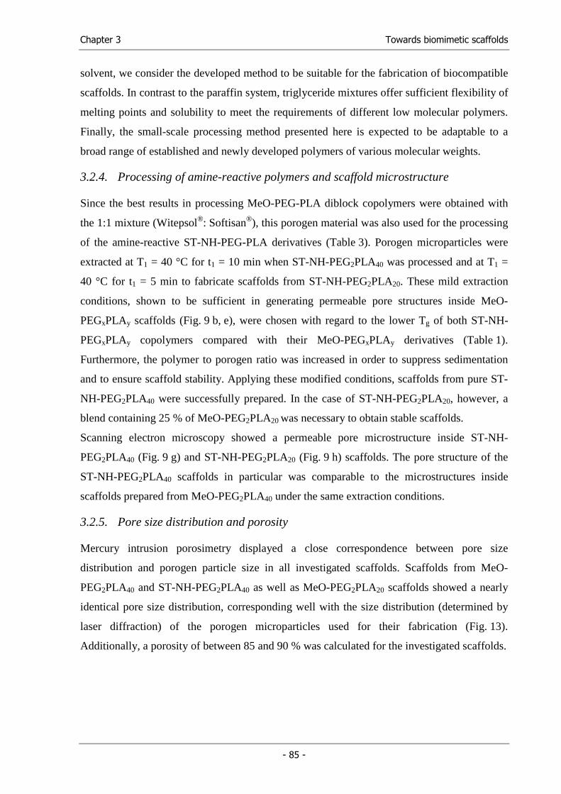
Chapter 3 Towards biomimetic scaffolds
- 85 -
solvent, we consider the developed method to be suitable for the fabrication of biocompatible
scaffolds. In contrast to the paraffin system, triglyceride mixtures offer sufficient flexibility of
melting points and solubility to meet the requirements of different low molecular polymers.
Finally, the small-scale processing method presented here is expected to be adaptable to a
broad range of established and newly developed polymers of various molecular weights.
3.2.4. Processing of amine-reactive polymers and scaffold microstructure
Since the best results in processing MeO-PEG-PLA diblock copolymers were obtained with
the 1:1 mixture (Witepsol®: Softisan®), this porogen material was also used for the processing
of the amine-reactive ST-NH-PEG-PLA derivatives (Table 3). Porogen microparticles were
extracted at T1 = 40 °C for t1 = 10 min when ST-NH-PEG2PLA40 was processed and at T1 =
40 °C for t1 = 5 min to fabricate scaffolds from ST-NH-PEG2PLA20. These mild extraction
conditions, shown to be sufficient in generating permeable pore structures inside MeO-
PEGxPLAy scaffolds (Fig. 9 b, e), were chosen with regard to the lower Tg of both ST-NH-
PEGxPLAy copolymers compared with their MeO-PEGxPLAy derivatives (Table 1).
Furthermore, the polymer to porogen ratio was increased in order to suppress sedimentation
and to ensure scaffold stability. Applying these modified conditions, scaffolds from pure ST-
NH-PEG2PLA40 were successfully prepared. In the case of ST-NH-PEG2PLA20, however, a
blend containing 25 % of MeO-PEG2PLA20 was necessary to obtain stable scaffolds.
Scanning electron microscopy showed a permeable pore microstructure inside ST-NH-
PEG2PLA40 (Fig. 9 g) and ST-NH-PEG2PLA20 (Fig. 9 h) scaffolds. The pore structure of the
ST-NH-PEG2PLA40 scaffolds in particular was comparable to the microstructures inside
scaffolds prepared from MeO-PEG2PLA40 under the same extraction conditions.
3.2.5. Pore size distribution and porosity
Mercury intrusion porosimetry displayed a close correspondence between pore size
distribution and porogen particle size in all investigated scaffolds. Scaffolds from MeO-
PEG2PLA40 and ST-NH-PEG2PLA40 as well as MeO-PEG2PLA20 scaffolds showed a nearly
identical pore size distribution, corresponding well with the size distribution (determined by
laser diffraction) of the porogen microparticles used for their fabrication (Fig. 13).
Additionally, a porosity of between 85 and 90 % was calculated for the investigated scaffolds.
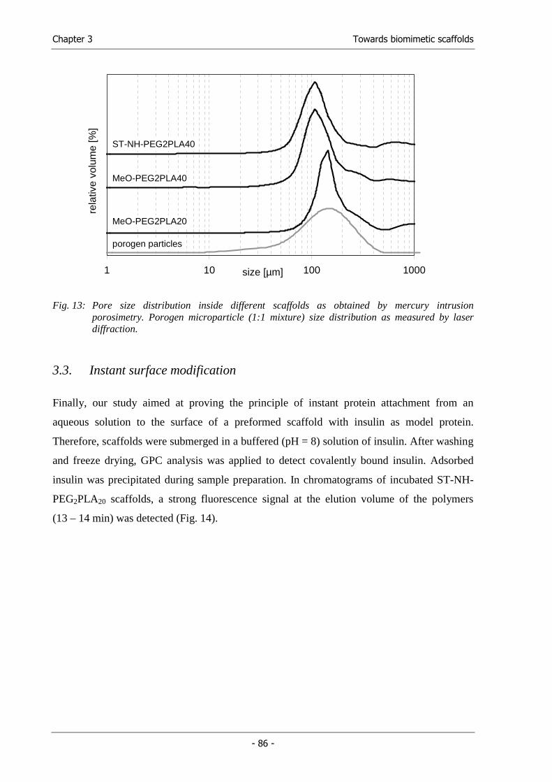
Chapter 3 Towards biomimetic scaffolds
- 86 -
1 10 100 1000size [µm]
rela
tive
volu
me
[%]
ST-NH-PEG2PLA40
MeO-PEG2PLA20
MeO-PEG2PLA40
porogen particles
Fig. 13: Pore size distribution inside different scaffolds as obtained by mercury intrusion
porosimetry. Porogen microparticle (1:1 mixture) size distribution as measured by laser diffraction.
3.3. Instant surface modification
Finally, our study aimed at proving the principle of instant protein attachment from an
aqueous solution to the surface of a preformed scaffold with insulin as model protein.
Therefore, scaffolds were submerged in a buffered (pH = 8) solution of insulin. After washing
and freeze drying, GPC analysis was applied to detect covalently bound insulin. Adsorbed
insulin was precipitated during sample preparation. In chromatograms of incubated ST-NH-
PEG2PLA20 scaffolds, a strong fluorescence signal at the elution volume of the polymers
(13 – 14 min) was detected (Fig. 14).
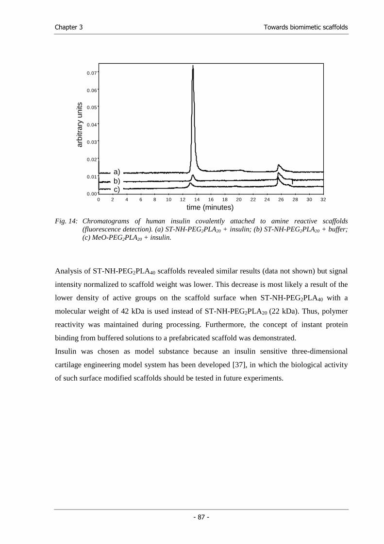
Chapter 3 Towards biomimetic scaffolds
- 87 -
0 2 4 6 8 10 12 14 16 18 20 22 24 26 28 30 320.00
0.01
0.02
0.03
0.04
0.05
0.06
0.07
arbi
trar
y un
its
time (minutes)
a)b)c)
Fig. 14: Chromatograms of human insulin covalently attached to amine reactive scaffolds
(fluorescence detection). (a) ST-NH-PEG2PLA20 + insulin; (b) ST-NH-PEG2PLA20 + buffer; (c) MeO-PEG2PLA20 + insulin.
Analysis of ST-NH-PEG2PLA40 scaffolds revealed similar results (data not shown) but signal
intensity normalized to scaffold weight was lower. This decrease is most likely a result of the
lower density of active groups on the scaffold surface when ST-NH-PEG2PLA40 with a
molecular weight of 42 kDa is used instead of ST-NH-PEG2PLA20 (22 kDa). Thus, polymer
reactivity was maintained during processing. Furthermore, the concept of instant protein
binding from buffered solutions to a prefabricated scaffold was demonstrated.
Insulin was chosen as model substance because an insulin sensitive three-dimensional
cartilage engineering model system has been developed [37], in which the biological activity
of such surface modified scaffolds should be tested in future experiments.
Chapter 3 Towards biomimetic scaffolds
- 88 -
4. Conclusions
We were able to process amine-reactive ST-NH-PEG-PLA diblock copolymers and their non-
reactive MeO-PEG-PLA derivatives into stable and highly porous scaffolds using an
anhydrous porogen leaching technique. ST-NH-PEG-PLA scaffolds were proven to be amine-
reactive after scaffold fabrication. This enables us to fabricate scaffolds for future applications
which can be easily conjugated with molecules containing free amine groups immediately
preceding implantation or use in cell culture experiments.
We demonstrated the superiority of triglyceride mixtures relative to paraffin as porogen
materials for scaffold fabrication especially with low molecular weight biodegradable
polymers. Their physiological tolerance and applicability in fabricating free flowing
microparticles of matching solubility and various melting points are outstanding
characteristics of such triglyceride blends. We showed that initial porogen melting at
extraction temperature was important in obtaining interconnected pore structures. However,
working with low molecular weight polymers requires careful consideration of the extraction
conditions. By combining high and low extraction temperatures with varying durations, as
well as using porogen materials with melting points near the glass transition temperature of
the polymer, the processing parameters were adapted to polymer properties.
5. Acknowledgements
The authors would like to thank Aventis Research & Technologies, Germany and the
Bundesministerium für Bildung und Forschung (BMBF) who sponsored this work. Special
thanks are due to Dr. D. Rose from the Working unit Material Investigation, University of
Regensburg, Germany for SEM images of the scaffolds fabricated using hard paraffin
microparticles. Thanks also go to SASOL Germany GmbH, Witten, Germany for providing
Dynasan®, Witepsol® and Softisan® and to Micromeritics, Mönchengladbach, Germany for
mercury intrusion porosimetry.
Chapter 3 Towards biomimetic scaffolds
- 89 -
6. References
(1) Langer R, Vacanti JP. 'Tissue engineering'. Science (1993); 260: 920-926.
(2) Hubbell JA. 'Biomaterials in tissue engineering'. Biotechnology (N Y ) (1995); 13: 565-576.
(3) Quirk RA, Chan WC, Davies MC, Tendler SJ, Shakesheff KM. 'Poly(L-lysine)-GRGDS as a biomimetic surface modifier for poly(lactic acid)'. Biomaterials (2001); 22: 865-872.
(4) Kantlehner M, Schaffner P, Finsinger D, Meyer J, Jonczyk A, Diefenbach B, Nies B, Holzemann G, Goodman SL, Kessler H. 'Surface Coating with Cyclic RGD Peptides Stimulates Osteoblast Adhesion and Proliferation as well as Bone Formation'. Chembiochem (2000); 1: 107-114.
(5) Shin MS, Kim SJ, Park SJ, Lee YH, Kim SI. 'Synthesis and characteristics of the interpenetrating polymer network hydrogel composed of chitosan and polyallylamine'. J Appl Polym Sci (2002); 86: 498-503.
(6) Massia SP, Stark J. 'Immobilized RGD peptides on surface-grafted dextran promote biospecific cell attachment'. J Biomed Mater Res (2001); 56: 390-399.
(7) Olbrich KC, Andersen TT, Blumenstock FA, Bizios R. 'Surfaces modified with covalently-immobilized adhesive peptides affect fibroblast population motility'. Biomaterials (1996); 17: 759-764.
(8) Zisch AH, Schenk U, Schense JC, Sakiyama-Elbert SE, Hubbell JA. 'Covalently conjugated VEGF-fibrin matrices for endothelialization'. J Control Release (2001); 72: 101-113.
(9) von-Recum H, Kikuchi A, Yamato M, Sakurai Y, Okano T, Kim SW. 'Growth factor and matrix molecules preserve cell function on thermally responsive culture surfaces'. Tissue Eng (1999); 5: 251-265.
(10) Sakiyama ES, Hubbell JA. 'Development of fibrin derivatives for controlled release of heparin-binding growth factors'. J Control Release (2000); 65: 389-402.
(11) Schense JC, Hubbell JA. 'Three-dimensional migration of neurites is mediated by adhesion site density and affinity'. J Biol Chem (2000); 275: 6813-6818.
(12) Rowley JA, Madlambayan G, Mooney DJ. 'Alginate hydrogels as synthetic extracellular matrix materials'. Biomaterials (1999); 20: 45-53.
(13) Gopferich A, Peter SJ, Lucke A, Lu L, Mikos AG. 'Modulation of marrow stromal cell function using poly(D,L-lactic acid)-block-poly(ethylene glycol)-monomethyl ether surfaces'. J Biomed Mater Res (1999); 46: 390-398.
Chapter 3 Towards biomimetic scaffolds
- 90 -
(14) Lucke A, Tessmar J, Schnell E, Schmeer G, Gopferich A. 'Biodegradable poly(,-lactic acid)-poly(ethylene glycol)-monomethyl ether diblock copolymers: structures and surface properties relevant to their use as biomaterials'. Biomaterials (2000); 21: 2361-2370.
(15) Lieb E, Tessmar J, Hacker M, Fischbach C, Rose D, Blunk T, Mikos AG, Goepferich A, Schulz MB. 'Poly(D,L-lactic acid)-Poly(ethylene glycol)-Monomethyl Ether Diblock Copolymers Control Adhesion and Osteoblastic Differentiation of Marrow Stromal Cells'. Tissue Eng (2003); 9: 71-84.
(16) Tessmar JK, Mikos AG, Goepferich A. 'Amine-Reactive Biodegradable Diblock Copolymers'. Biomacromolecules (2002); 3: 194-200.
(17) Hermanson GT. Bioconjugate techniques. San Diego: Academic Press, 1996.
(18) Greenwald RB. 'PEG drugs: an overview'. J Control Release (2001); 74: 159-171.
(19) Bailon P, Berthold W. 'Polyethylene glycol-conjugated pharmaceutical proteins'. Pharm Sci Technol Today (1998); 1: 352-356.
(20) Kellner K, Liebsch G, Klimant I, Wolfbeis OS, Blunk T, Schulz MB, Gopferich A. 'Determination of oxygen gradients in engineered tissue using a fluorescent sensor'. Biotechnol Bioeng (2002); 80: 73-83.
(21) Obradovic B, Carrier RL, Vunjak-Novakovic G, Freed LE. 'Gas exchange is essential for bioreactor cultivation of tissue engineered cartilage'. Biotechnol Bioeng (1999); 63: 197-205.
(22) Lu L, Mikos AG. 'The importance of New Processing Techniques in Tissue Engineering'. MRS Bull (1996); 21: 28-32.
(23) Goldstein AS, Zhu G, Morris GE, Meszlenyi RK, Mikos AG. 'Effect of osteoblastic culture conditions on the structure of poly(DL-lactic-co-glycolic acid) foam scaffolds'. Tissue Eng (1999); 5: 421-434.
(24) Widmer MS, Gupta PK, Lu L, Meszlenyi RK, Evans GR, Brandt K, Savel T, Gurlek A, Patrick-CW J, Mikos AG. 'Manufacture of porous biodegradable polymer conduits by an extrusion process for guided tissue regeneration'. Biomaterials (1998); 19: 1945-1955.
(25) Sheridan MH, Shea LD, Peters MC, Mooney DJ. 'Bioabsorbable polymer scaffolds for tissue engineering capable of sustained growth factor delivery'. J Control Release (2000); 64: 91-102.
(26) Harris LD, Kim BS, Mooney DJ. 'Open pore biodegradable matrices formed with gas foaming'. J Biomed Mater Res (1998); 42: 396-402.
(27) Shastri VP, Martin I, Langer R. 'Novel versatile process for the production of polymer foams'. Mat Res Soc Proc (1999); 550: 149-153.
(28) Ma PX, Choi JW. 'Biodegradable polymer scaffolds with well-defined interconnected spherical pore network'. Tissue Eng (2001); 7: 23-33.
Chapter 3 Towards biomimetic scaffolds
- 91 -
(29) Shastri VP, Martin I, Langer R. 'Macroporous polymer foams by hydrocarbon templating'. Proc Natl Acad Sci U S A (2000); 97: 1970-1975.
(30) Martin I, Shastri VP, Padera RF, Yang J, Mackay AJ, Langer R, Vunjak-Novakovic G, Freed LE. 'Selective differentiation of mammalian bone marrow stromal cells cultured on three-dimensional polymer foams'. J Biomed Mater Res (2001); 55: 229-235.
(31) Hiaki T, Kurihara K, Kojima K. 'Vapor-Liquid Equilibria for Acetone + Chloroform + Methanol and Constituent Binary Systems at 101.3 kPa'. J Chem Eng Data (1994); 39: 714-719.
(32) Ho WS, Chan AC, Law BK. 'Management of paraffinoma of the breast: 10 years' experience'. Br J Plast Surg (2001); 54: 232-234.
(33) Munchow H. 'Paraffin-oil damage to tissue as in the example of calcified paraffinomas in mammae'. Radiol Diagn (Berl) (1966); 7: 743-747.
(34) Muller RH, Mader K, Gohla S. 'Solid lipid nanoparticles (SLN) for controlled drug delivery - a review of the state of the art'. Eur J Pharm Biopharm (2000); 50: 161-177.
(35) Mehnert W, Mader K. 'Solid lipid nanoparticles; Production, characterization and applications'. Adv Drug Delivery Rev (2001); 47: 165-196.
(36) International Conference on Harmonisation of technical requirements for registration of pharmaceuticals for human use. ICH harmonized Tripartite Guideline (Q3C) Impurities: Residual solvents. Draft 4 (1997). Available from http://www.ich.org
(37) Kellner K, Schulz MB, Gopferich A, Blunk T. 'Insulin in tissue engineering of cartilage: A potential model system for growth factor application'. J Drug Targeting (2001); 9: 439-448.

Functional Cell Carriers for Tissue Engineering
Chapter 4
Hansen Solubility Parameters as a Means to Replace Halogenated Solvents in
Biomaterial Processing
Michael Hacker1, Andrea Blaimer1, Michaela B. Schulz1,2, Achim Göpferich1
1 Department of Pharmaceutical Technology, University of Regensburg,
Universitaetsstrasse 31, 93040 Regensburg, Germany 2 Department of Pharmaceutical Technology, University of Graz,
Schubertstrasse 6, 8010 Graz, Austria
European Journal of Pharmaceutics and Biopharmaceutics (to be submitted)
Abstract
Hansen solubility parameters (HSPs) are accepted tools to describe the thermodynamic
interactions between solvent molecules and polymers. In this study, these parameters were
employed to systematically replace halogens and other toxic solvents used in an established
scaffold fabrication technique with solvents with a low toxicity rating (ICH guideline Q3C)
without any changes to the other processing parameters. To systematically search for solvent
alternatives, the HSPs of the original solvent mixture were calculated and compared to the
parameters of 26 class 3 solvents and binary mixtures thereof. The HSPs of a mixture
containing methyl ethyl ketone 59% (v/v) and tetrahydrofurane 41% (v/v) were found to most
closely fit the parameters calculated for the original acetone-chloroform-mixture. Using the
alternative solvent mixture, poly(lactic-co-glycolic acid) and monomethyl ether-poly(ethylene
glycol)-co-poly(lactic acid) could be processed into tissue engineering scaffolds without
further changes to the procedure. Importantly, the solvent exchange only minimally affected
the macro- and microstructure of the resulting scaffolds.
Chapter 4 Solvent Replacement
- 95 -
1. Introduction
Since 1970, when poly(glycolic acid) (PGA) was approved by the FDA for the use as a
degradable suture material, the application of biodegradable polymers, especially poly(α-
hydroxy acids), has proliferated throughout the biomaterial and medical sciences [1,2]. A
plethora of drug release devices, orthopedic implants and fixation devices as well as cell
carriers for tissue engineering applications have been fabricated from these materials [3-7].
Since lipophilic materials are not water-soluble, they must be processed either in their molten
state or dissolved in organic solvents. In particular, the fabrication of microparticles and tissue
engineering scaffolds from biodegradable polymers often employs halogenated solvents, such
as methylene chloride and chloroform [8,9]. The elimination of these toxic solvents from such
fabrication procedures, however, is necessary to avoid risks to human health and minimize
any influence on the physicochemical properties of the product, such as microstructure,
storage stability or the stability of encapsulated substances [10]. In tissue engineering
applications, residual solvents may compromise cell development on the polymeric carriers.
Due to their toxicity, regulatory authorities strictly limit halogenated solvent residuals. The
International Conference on Harmonization (ICH), a project that brought together the
regulatory authorities of Europe, Japan and the United States, published a guideline for
residual solvents [11] that classifies the chemicals on the basis of their toxicity and gives
exposure limits for each solvent. Halogenated solvents, such as methylene chloride and
chloroform, are categorized as ‘solvents to be limited’ (class 2 solvents). Less toxic chemicals
are labeled as class 3 solvents by this guideline (Table 1). Therefore, class 3 solvents should
be used to replace halogenated solvents in biomaterial processing wherever possible.
This study particularly aimed at eliminating chloroform from a recently developed scaffold
fabrication procedure [12]. This anhydrous porogen leaching technique allows for the
processing of poly(lactic-co-glycolic acid) (PLGA) and diblock copolymers consisting of
poly(ethylene glycol) (PEG) and poly(lactic acid) (PLA) into macroporous cell carriers
(scaffolds) with an interconnected pore structure. In the first step of the process, an azeotropic
mixture containing 65% (v/v) acetone and 35% (v/v) chloroform is used to dissolve the
polymers. Solid lipid microparticles, the pore forming templates, are dispersed in the polymer
solution and the dispersion is transferred into molds. Polymer precipitation and microparticle
extraction are simultaneously initiated by submerging the molds in warm n-hexane [12]. To
obtain macroporous, form-filling scaffolds, processes like solvent extraction, phase separation
and porogen extraction have been carefully examined and related to each other during this
Chapter 4 Solvent Replacement
- 96 -
processing step. The process temperature and solvent composition are the key parameters in
controlling these processes. With regard to the ICH guideline, we aimed at replacing
chloroform by exclusively using class 3 solvents or mixtures thereof. However, the previously
determined parameters for polymer processing should remain applicable. We hypothesized
that by employing a solvent or a solvent mixture with solubility and miscibility properties
comparable to the established acetone-chloroform-mixture, the substitution could successfully
be accomplished. To avoid laborious empirical screenings, Hansen solubility parameters
(HSPs) were used for a systematical search. We calculated the HSPs of the original acetone-
chloroform-mixture and compared them to the parameters of 26 class 3 solvents and binary
mixtures thereof. The solvent mixture, which most closely fit the acetone-chloroform-mixture,
was used for PLGA and MeO-PEG-PLA processing without additional parameter changes.
The macro- and microstructure of the resulting scaffolds was examined to determine the effect
of the solvent exchange. Several class 3 solvents, which have similar HSPs to the acetone-
chloroform-mixture, were also tested as polymer solvents.
Chapter 4 Solvent Replacement
- 97 -
2. Theory
The solubility parameter theory was originally established to describe the enthalpy of mixing
of nonpolar, nonassociated solvents, but has been extended to apply to polar solvents and
polymers. In coatings and paint technology, the solubility parameter is important for the
selection of solvents and polymer plasticizers as well as to predict polymer and solvent
compatibility with dyes, nonionic emulsifiers and pigments.
Hildebrand defined the total solubility parameter (δ) as the square root of the cohesive energy
density (CED) [13], which is equal to the energy of vaporization (∆Ev) per molar volume
(Vm):
m
v
V
ECED
∆==δ (1)
The solubility parameter is a measure of all the intermolecular forces responsible for the
material cohesion.
To predict interactions between two solvents or a solvent and a polymer, the difference
between the solubility parameters of the molecules is determined. Similar solubility parameter
values, resulting in a small difference, indicate strong interactions, meaning that two solvents
are miscible or that the polymer will dissolve in the solvent.
With the objective of describing the quality of the interaction between two molecules more
precisely, the total solubility parameter was decomposed into several terms representing
different contributions to the free energy of mixing [14]. In the three-parameter (three-
dimensional) Hansen approach, the interaction capacity of a compound arises from three
partial solubility parameters that quantitatively describe the non-polar, dispersive interactions
(δd), permanent dipole-dipole interactions (δp), and the hydrogen bonding forces (δh) [15-18].
The total solubility parameter is related to the partial ones by the following equation:
2222hpdtotal δδδδ ++= (2)
The values of the HSPs for many solvents were calculated from a large number of solubility
data sets and are tabulated in literature [19]. In Table 1, the HSPs for the ICH class 3 solvents
are listed based on published data [19]. Polymer solubility parameters can also be
decomposed to a three-term set. Determination of this data, however, is a difficult and
laborious undertaking. Nevertheless, the published total solubility parameter value of PLA is
9.8 – 10.2 cal1/2cm-3/2 [20], which is equal to 20.1 – 20.9 MPa1/2.
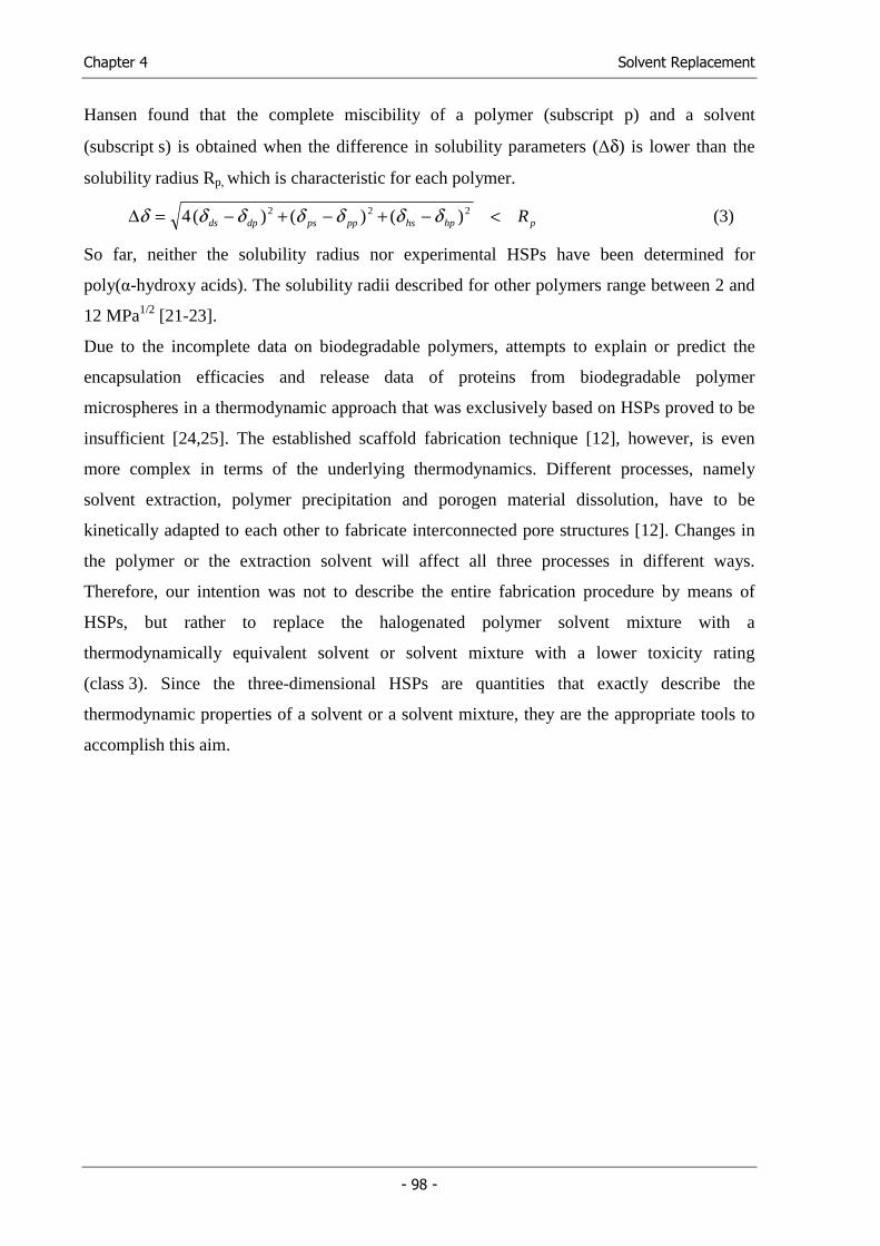
Chapter 4 Solvent Replacement
- 98 -
Hansen found that the complete miscibility of a polymer (subscript p) and a solvent
(subscript s) is obtained when the difference in solubility parameters (∆δ) is lower than the
solubility radius Rp, which is characteristic for each polymer.
phphspppsdpds R<−+−+−=∆ 222 )()()(4 δδδδδδδ (3)
So far, neither the solubility radius nor experimental HSPs have been determined for
poly(α-hydroxy acids). The solubility radii described for other polymers range between 2 and
12 MPa1/2 [21-23].
Due to the incomplete data on biodegradable polymers, attempts to explain or predict the
encapsulation efficacies and release data of proteins from biodegradable polymer
microspheres in a thermodynamic approach that was exclusively based on HSPs proved to be
insufficient [24,25]. The established scaffold fabrication technique [12], however, is even
more complex in terms of the underlying thermodynamics. Different processes, namely
solvent extraction, polymer precipitation and porogen material dissolution, have to be
kinetically adapted to each other to fabricate interconnected pore structures [12]. Changes in
the polymer or the extraction solvent will affect all three processes in different ways.
Therefore, our intention was not to describe the entire fabrication procedure by means of
HSPs, but rather to replace the halogenated polymer solvent mixture with a
thermodynamically equivalent solvent or solvent mixture with a lower toxicity rating
(class 3). Since the three-dimensional HSPs are quantities that exactly describe the
thermodynamic properties of a solvent or a solvent mixture, they are the appropriate tools to
accomplish this aim.
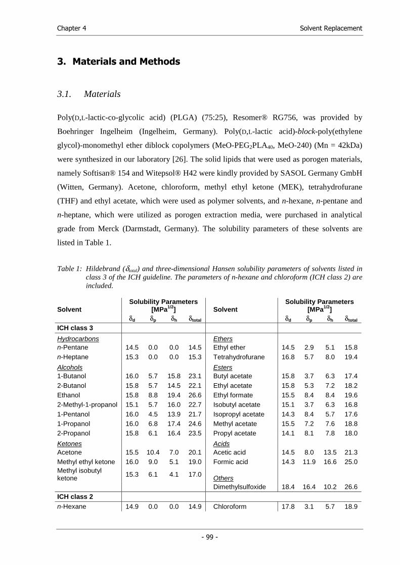
Chapter 4 Solvent Replacement
- 99 -
3. Materials and Methods
3.1. Materials
Poly(D,L-lactic-co-glycolic acid) (PLGA) (75:25), Resomer® RG756, was provided by
Boehringer Ingelheim (Ingelheim, Germany). Poly(D,L-lactic acid)-block-poly(ethylene
glycol)-monomethyl ether diblock copolymers (MeO-PEG2PLA40, MeO-240) (Mn = 42kDa)
were synthesized in our laboratory [26]. The solid lipids that were used as porogen materials,
namely Softisan® 154 and Witepsol® H42 were kindly provided by SASOL Germany GmbH
(Witten, Germany). Acetone, chloroform, methyl ethyl ketone (MEK), tetrahydrofurane
(THF) and ethyl acetate, which were used as polymer solvents, and n-hexane, n-pentane and
n-heptane, which were utilized as porogen extraction media, were purchased in analytical
grade from Merck (Darmstadt, Germany). The solubility parameters of these solvents are
listed in Table 1.
Table 1: Hildebrand (δtotal) and three-dimensional Hansen solubility parameters of solvents listed in class 3 of the ICH guideline. The parameters of n-hexane and chloroform (ICH class 2) are included.
Solvent
Solubility Parameters [MPa1/2] Solvent
Solubility Parameters [MPa1/2]
δd δp δh δtotal δd δp δh δtotal ICH class 3
Hydrocarbons Ethers n-Pentane 14.5 0.0 0.0 14.5 Ethyl ether 14.5 2.9 5.1 15.8 n-Heptane 15.3 0.0 0.0 15.3 Tetrahydrofurane 16.8 5.7 8.0 19.4
Alcohols Esters 1-Butanol 16.0 5.7 15.8 23.1 Butyl acetate 15.8 3.7 6.3 17.4 2-Butanol 15.8 5.7 14.5 22.1 Ethyl acetate 15.8 5.3 7.2 18.2 Ethanol 15.8 8.8 19.4 26.6 Ethyl formate 15.5 8.4 8.4 19.6 2-Methyl-1-propanol 15.1 5.7 16.0 22.7 Isobutyl acetate 15.1 3.7 6.3 16.8 1-Pentanol 16.0 4.5 13.9 21.7 Isopropyl acetate 14.3 8.4 5.7 17.6 1-Propanol 16.0 6.8 17.4 24.6 Methyl acetate 15.5 7.2 7.6 18.8 2-Propanol 15.8 6.1 16.4 23.5 Propyl acetate 14.1 8.1 7.8 18.0
Ketones Acids Acetone 15.5 10.4 7.0 20.1 Acetic acid 14.5 8.0 13.5 21.3 Methyl ethyl ketone 16.0 9.0 5.1 19.0 Formic acid 14.3 11.9 16.6 25.0 Methyl isobutyl ketone 15.3 6.1 4.1 17.0
Others
Dimethylsulfoxide 18.4 16.4 10.2 26.6
ICH class 2 n-Hexane 14.9 0.0 0.0 14.9 Chloroform 17.8 3.1 5.7 18.9
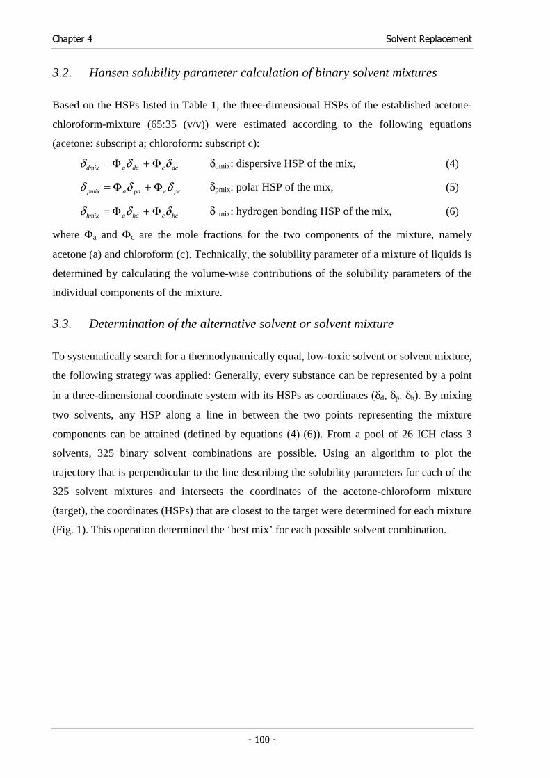
Chapter 4 Solvent Replacement
- 100 -
3.2. Hansen solubility parameter calculation of binary solvent mixtures
Based on the HSPs listed in Table 1, the three-dimensional HSPs of the established acetone-
chloroform-mixture (65:35 (v/v)) were estimated according to the following equations
(acetone: subscript a; chloroform: subscript c):
dccdaadmix δδδ Φ+Φ= δdmix: dispersive HSP of the mix, (4)
pccpaapmix δδδ Φ+Φ= δpmix: polar HSP of the mix, (5)
hcchaahmix δδδ Φ+Φ= δhmix: hydrogen bonding HSP of the mix, (6)
where Φa and Φc are the mole fractions for the two components of the mixture, namely
acetone (a) and chloroform (c). Technically, the solubility parameter of a mixture of liquids is
determined by calculating the volume-wise contributions of the solubility parameters of the
individual components of the mixture.
3.3. Determination of the alternative solvent or solvent mixture
To systematically search for a thermodynamically equal, low-toxic solvent or solvent mixture,
the following strategy was applied: Generally, every substance can be represented by a point
in a three-dimensional coordinate system with its HSPs as coordinates (δd, δp, δh). By mixing
two solvents, any HSP along a line in between the two points representing the mixture
components can be attained (defined by equations (4)-(6)). From a pool of 26 ICH class 3
solvents, 325 binary solvent combinations are possible. Using an algorithm to plot the
trajectory that is perpendicular to the line describing the solubility parameters for each of the
325 solvent mixtures and intersects the coordinates of the acetone-chloroform mixture
(target), the coordinates (HSPs) that are closest to the target were determined for each mixture
(Fig. 1). This operation determined the ‘best mix’ for each possible solvent combination.
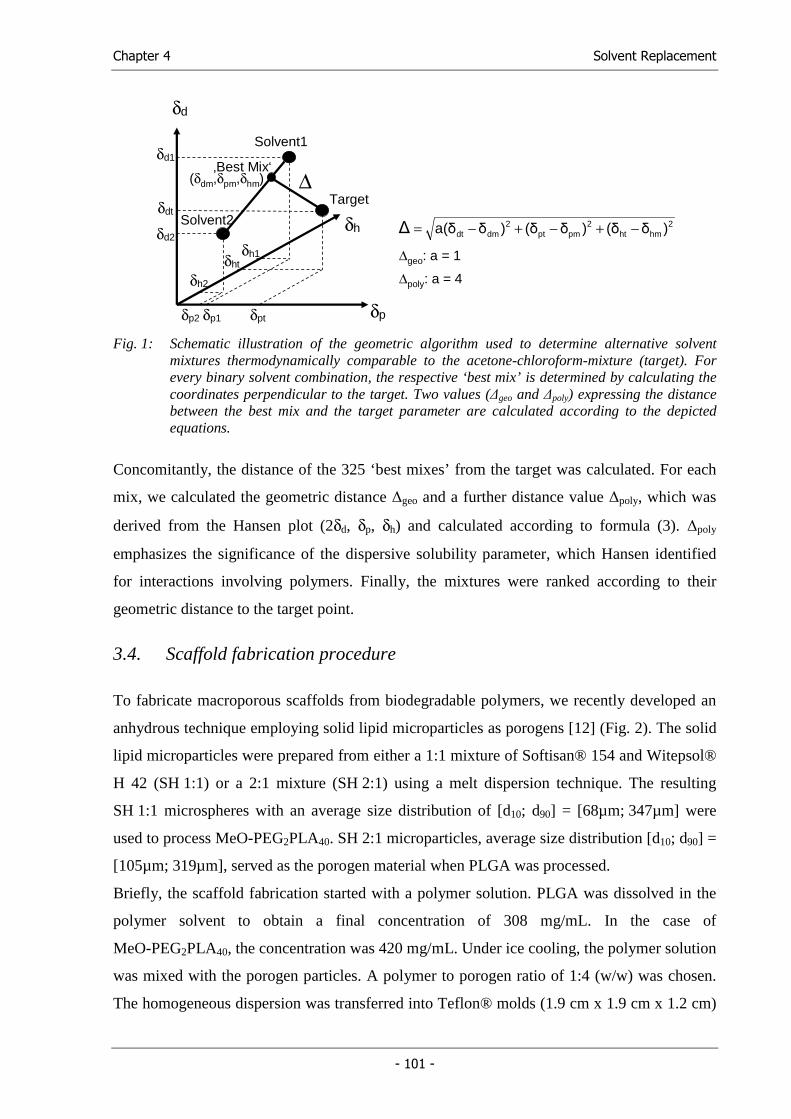
Chapter 4 Solvent Replacement
- 101 -
δd
δh
δp
∆
Solvent2
Solvent1
Target
δd1
δdt
δd2
δp1 δptδp2
δhtδh1
δh2
‚Best Mix‘(δdm,δpm,δhm)
∆geo: a = 1
∆poly: a = 4
2hmht
2pmpt
2dmdt )δ(δ)δ(δ)δa(δ∆ −+−+−=
Fig. 1: Schematic illustration of the geometric algorithm used to determine alternative solvent
mixtures thermodynamically comparable to the acetone-chloroform-mixture (target). For every binary solvent combination, the respective ‘best mix’ is determined by calculating the coordinates perpendicular to the target. Two values (∆geo and ∆poly) expressing the distance between the best mix and the target parameter are calculated according to the depicted equations.
Concomitantly, the distance of the 325 ‘best mixes’ from the target was calculated. For each
mix, we calculated the geometric distance ∆geo and a further distance value ∆poly, which was
derived from the Hansen plot (2δd, δp, δh) and calculated according to formula (3). ∆poly
emphasizes the significance of the dispersive solubility parameter, which Hansen identified
for interactions involving polymers. Finally, the mixtures were ranked according to their
geometric distance to the target point.
3.4. Scaffold fabrication procedure
To fabricate macroporous scaffolds from biodegradable polymers, we recently developed an
anhydrous technique employing solid lipid microparticles as porogens [12] (Fig. 2). The solid
lipid microparticles were prepared from either a 1:1 mixture of Softisan® 154 and Witepsol®
H 42 (SH 1:1) or a 2:1 mixture (SH 2:1) using a melt dispersion technique. The resulting
SH 1:1 microspheres with an average size distribution of [d10; d90] = [68µm; 347µm] were
used to process MeO-PEG2PLA40. SH 2:1 microparticles, average size distribution [d10; d90] =
[105µm; 319µm], served as the porogen material when PLGA was processed.
Briefly, the scaffold fabrication started with a polymer solution. PLGA was dissolved in the
polymer solvent to obtain a final concentration of 308 mg/mL. In the case of
MeO-PEG2PLA40, the concentration was 420 mg/mL. Under ice cooling, the polymer solution
was mixed with the porogen particles. A polymer to porogen ratio of 1:4 (w/w) was chosen.
The homogeneous dispersion was transferred into Teflon® molds (1.9 cm x 1.9 cm x 1.2 cm)
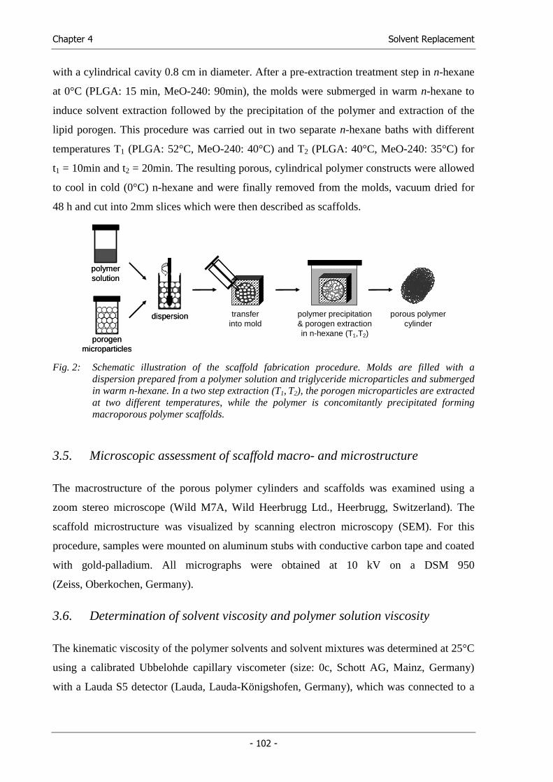
Chapter 4 Solvent Replacement
- 102 -
with a cylindrical cavity 0.8 cm in diameter. After a pre-extraction treatment step in n-hexane
at 0°C (PLGA: 15 min, MeO-240: 90min), the molds were submerged in warm n-hexane to
induce solvent extraction followed by the precipitation of the polymer and extraction of the
lipid porogen. This procedure was carried out in two separate n-hexane baths with different
temperatures T1 (PLGA: 52°C, MeO-240: 40°C) and T2 (PLGA: 40°C, MeO-240: 35°C) for
t1 = 10min and t2 = 20min. The resulting porous, cylindrical polymer constructs were allowed
to cool in cold (0°C) n-hexane and were finally removed from the molds, vacuum dried for
48 h and cut into 2mm slices which were then described as scaffolds.
polymersolutionpolymersolution
porogenmicroparticles
porogenmicroparticles
polymer precipitation & porogen extractionin n-hexane (T1,T2)
porous polymercylinder
dispersiondispersion transferinto mold
Fig. 2: Schematic illustration of the scaffold fabrication procedure. Molds are filled with a
dispersion prepared from a polymer solution and triglyceride microparticles and submerged in warm n-hexane. In a two step extraction (T1, T2), the porogen microparticles are extracted at two different temperatures, while the polymer is concomitantly precipitated forming macroporous polymer scaffolds.
3.5. Microscopic assessment of scaffold macro- and microstructure
The macrostructure of the porous polymer cylinders and scaffolds was examined using a
zoom stereo microscope (Wild M7A, Wild Heerbrugg Ltd., Heerbrugg, Switzerland). The
scaffold microstructure was visualized by scanning electron microscopy (SEM). For this
procedure, samples were mounted on aluminum stubs with conductive carbon tape and coated
with gold-palladium. All micrographs were obtained at 10 kV on a DSM 950
(Zeiss, Oberkochen, Germany).
3.6. Determination of solvent viscosity and polymer solution viscosity
The kinematic viscosity of the polymer solvents and solvent mixtures was determined at 25°C
using a calibrated Ubbelohde capillary viscometer (size: 0c, Schott AG, Mainz, Germany)
with a Lauda S5 detector (Lauda, Lauda-Königshofen, Germany), which was connected to a
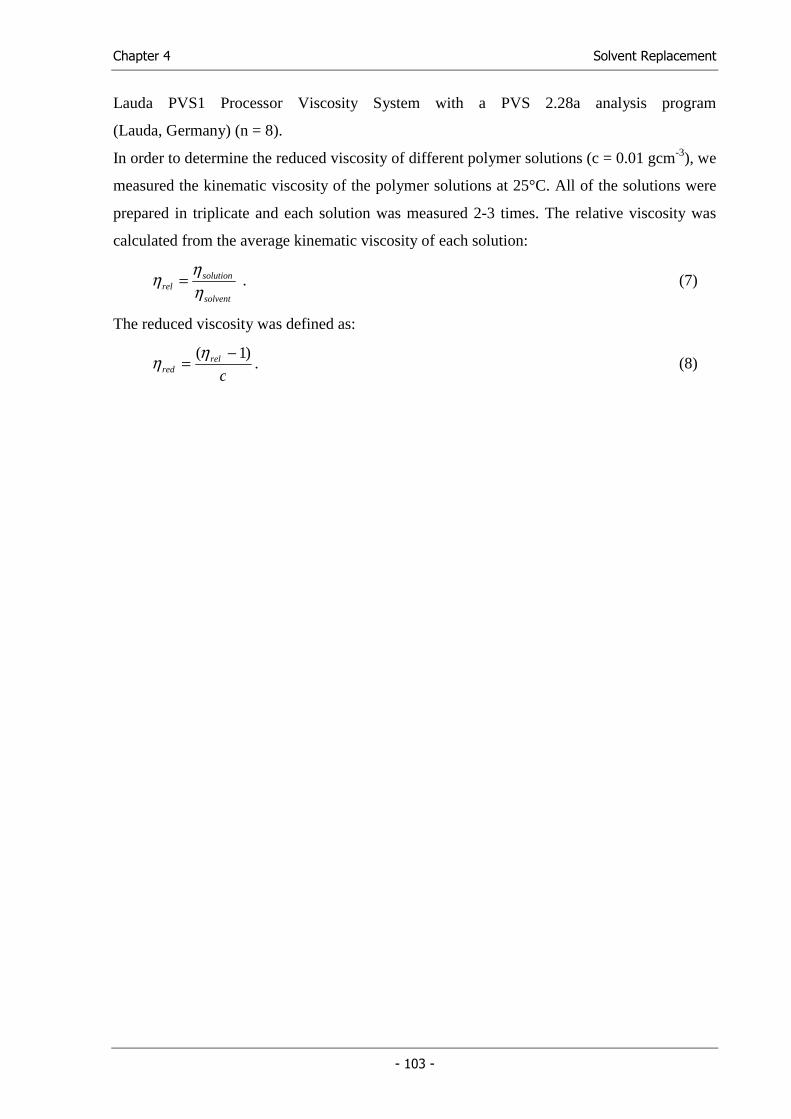
Chapter 4 Solvent Replacement
- 103 -
Lauda PVS1 Processor Viscosity System with a PVS 2.28a analysis program
(Lauda, Germany) (n = 8).
In order to determine the reduced viscosity of different polymer solutions (c = 0.01 gcm-3), we
measured the kinematic viscosity of the polymer solutions at 25°C. All of the solutions were
prepared in triplicate and each solution was measured 2-3 times. The relative viscosity was
calculated from the average kinematic viscosity of each solution:
solvent
solutionrel η
ηη = . (7)
The reduced viscosity was defined as:
c
relred
)1( −=
ηη . (8)
Chapter 4 Solvent Replacement
- 104 -
4. Results
4.1. Determination of low-toxic solvent alternatives
A total of 28 solvents are classified as ‘solvents with low toxic potential’ in class 3 of the ICH
guideline ‘Impurities: Guideline for residual solvents’ [11]. Table 1 lists 26 class 3 solvents
and the corresponding HSPs. Anisole and cumene, which also are class 3 solvents, were not
considered in this study. Generally, the solvents listed in this class belong to several chemical
substance classes ranging from non-polar hydrocarbons to alcohols and acids that show strong
hydrogen bonding. This way, the class 3 solvents offer a broad spectrum of solubility
parameters to choose from.
The solvents used in the original scaffold fabrication procedure are n-hexane, acetone and
chloroform, with acetone and chloroform being used as a mixture to dissolve the polymer and
n-hexane serving as extraction solvent. According to the ICH guideline, chloroform and n-
hexane are classified as ‘solvents to be limited’ (class 2). The HSPs of these two solvents are
listed in Table 2.
The main goal of this study was to find an alternative to the established acetone-chloroform-
mixture (65:35 (v/v)) used as the polymer solvent. To define a measure for the
thermodynamic interaction forces of this mixture, its HSPs were calculated according to
equations (4)-(6). The parameters of the acetone-chloroform-mixture, representing the target
coordinates for the systematic search, are listed in Table 2. An algorithm, described in the
methods section, was used to compare the HSPs of 26 class 3 solvents and their binary
mixtures with the target mixture in order to screen for a thermodynamically equal or at least
similar solvent alternative. The ten best mixtures are listed in Table 2. All of them exhibited a
geometric distance (∆geo) from the target below 1 MPa1/2. A mixture of methyl ethyl ketone
and tetrahydrofurane (59:41 (v/v)) fit best in terms of both ∆geo and ∆poly. In contrast to ∆geo,
which represents the spatial distance of the mixture HSPs to the target in a 3-D coordinate
system (δd, δp, δh), ∆poly is based on the Hansen plot (2δd, δp, δh) that emphasizes the disperse
interactions between polymer and solvent. Like four other mixtures, all indicated with a star
(*) in Table 2, this mixture is free of nucleophilic solvents and therefore suitable for the
processing of functional, electrophilic, reactive polymers [27].
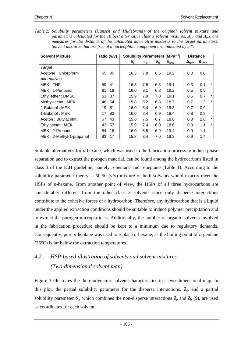
Chapter 4 Solvent Replacement
- 105 -
Table 2: Solubility parameters (Hansen and Hildebrand) of the original solvent mixture and parameters calculated for the 10 best alternative class 3 solvent mixtures. ∆geo and ∆poly are measures for the distance of the calculated alternative mixtures to the target parameters. Solvent mixtures that are free of a nucleophilic component are indicated by a *.
Solvent Mixture ratio (v/v) Solubility Parameters [MPa1/2] Distance δd δp δh δtotal ∆geo ∆poly Target Acetone : Chloroform 65 : 35 16.3 7.8 6.5 19.2 0.0 0.0 Alternatives MEK : THF 59 : 41 16.3 7.6 6.3 19.1 0.3 0.1 * MEK : 1-Pentanol 81 : 19 16.0 8.1 6.8 19.2 0.5 0.5 Ethyl ether : DMSO 63 : 37 15.9 7.9 7.0 19.1 0.6 0.7 * Methylacetat : MEK 46 : 54 15.8 8.2 6.3 18.7 0.7 1.3 * 2-Butanol : MEK 19 : 81 16.0 8.4 6.9 19.3 0.7 0.9 1-Butanol : MEK 17 : 83 16.0 8.4 6.9 19.4 0.8 0.9 Aceton : Butylacetat 57 : 43 15.6 7.5 6.7 18.6 0.8 2.0 * Ethylacetat : MEK 43 : 57 15.9 7.4 6.0 18.6 0.8 1.1 * MEK : 2-Propanol 84 : 16 16.0 8.5 6.9 19.4 0.9 1.1 MEK : 2-Methyl-1-propanol 83 : 17 15.8 8.4 7.0 19.3 0.9 1.4
Suitable alternatives for n-hexane, which was used in the fabrication process to induce phase
separation and to extract the porogen material, can be found among the hydrocarbons listed in
class 3 of the ICH guideline, namely n-pentane and n-heptane (Table 1). According to the
solubility parameter theory, a 50:50 (v/v) mixture of both solvents would exactly meet the
HSPs of n-hexane. From another point of view, the HSPs of all three hydrocarbons are
considerably different from the other class 3 solvents since only disperse interactions
contribute to the cohesive forces of a hydrocarbon. Therefore, any hydrocarbon that is a liquid
under the applied extraction conditions should be suitable to induce polymer precipitation and
to extract the porogen microparticles. Additionally, the number of organic solvents involved
in the fabrication procedure should be kept to a minimum due to regulatory demands.
Consequently, pure n-heptane was used to replace n-hexane, as the boiling point of n-pentane
(36°C) is far below the extraction temperatures.
4.2. HSP-based illustration of solvents and solvent mixtures
(Two-dimensional solvent map)
Figure 3 illustrates the thermodynamic solvent characteristics in a two-dimensional map. In
this plot, the partial solubility parameter for the disperse interactions, δd, and a partial
solubility parameter δa, which combines the non-disperse interactions δp and δh (9), are used
as coordinates for each solvent.
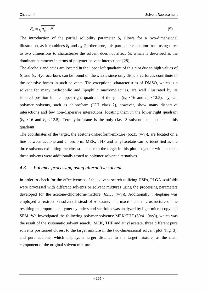
Chapter 4 Solvent Replacement
- 106 -
22hpa δδδ += (9)
The introduction of the partial solubility parameter δa allows for a two-dimensional
illustration, as it combines δp and δh. Furthermore, this particular reduction from using three
to two dimensions to characterize the solvent does not affect δd, which is described as the
dominant parameter in terms of polymer-solvent interactions [28].
The alcohols and acids are located in the upper left quadrant of this plot due to high values of
δp and δh. Hydrocarbons can be found on the x-axis since only dispersive forces contribute to
the cohesive forces in such solvents. The exceptional characteristics of DMSO, which is a
solvent for many hydrophilic and lipophilic macromolecules, are well illustrated by its
isolated position in the upper right quadrant of the plot (δd > 16 and δa > 12.5). Typical
polymer solvents, such as chloroform (ICH class 2), however, show many dispersive
interactions and few non-dispersive interactions, locating them in the lower right quadrant
(δd > 16 and δa < 12.5). Tetrahydrofurane is the only class 3 solvent that appears in this
quadrant.
The coordinates of the target, the acetone-chloroform-mixture (65:35 (v/v)), are located on a
line between acetone and chloroform. MEK, THF and ethyl acetate can be identified as the
three solvents exhibiting the closest distance to the target in this plot. Together with acetone,
these solvents were additionally tested as polymer solvent alternatives.
4.3. Polymer processing using alternative solvents
In order to check for the effectiveness of the solvent search utilizing HSPs, PLGA scaffolds
were processed with different solvents or solvent mixtures using the processing parameters
developed for the acetone-chloroform-mixture (65:35 (v/v)). Additionally, n-heptane was
employed as extraction solvent instead of n-hexane. The macro- and microstructure of the
resulting macroporous polymer cylinders and scaffolds was analyzed by light microscopy and
SEM. We investigated the following polymer solvents: MEK:THF (59:41 (v/v)), which was
the result of the systematic solvent search, MEK, THF and ethyl acetate, three different pure
solvents positioned closest to the target mixture in the two-dimensional solvent plot (Fig. 3),
and pure acetone, which displays a larger distance to the target mixture, as the main
component of the original solvent mixture.
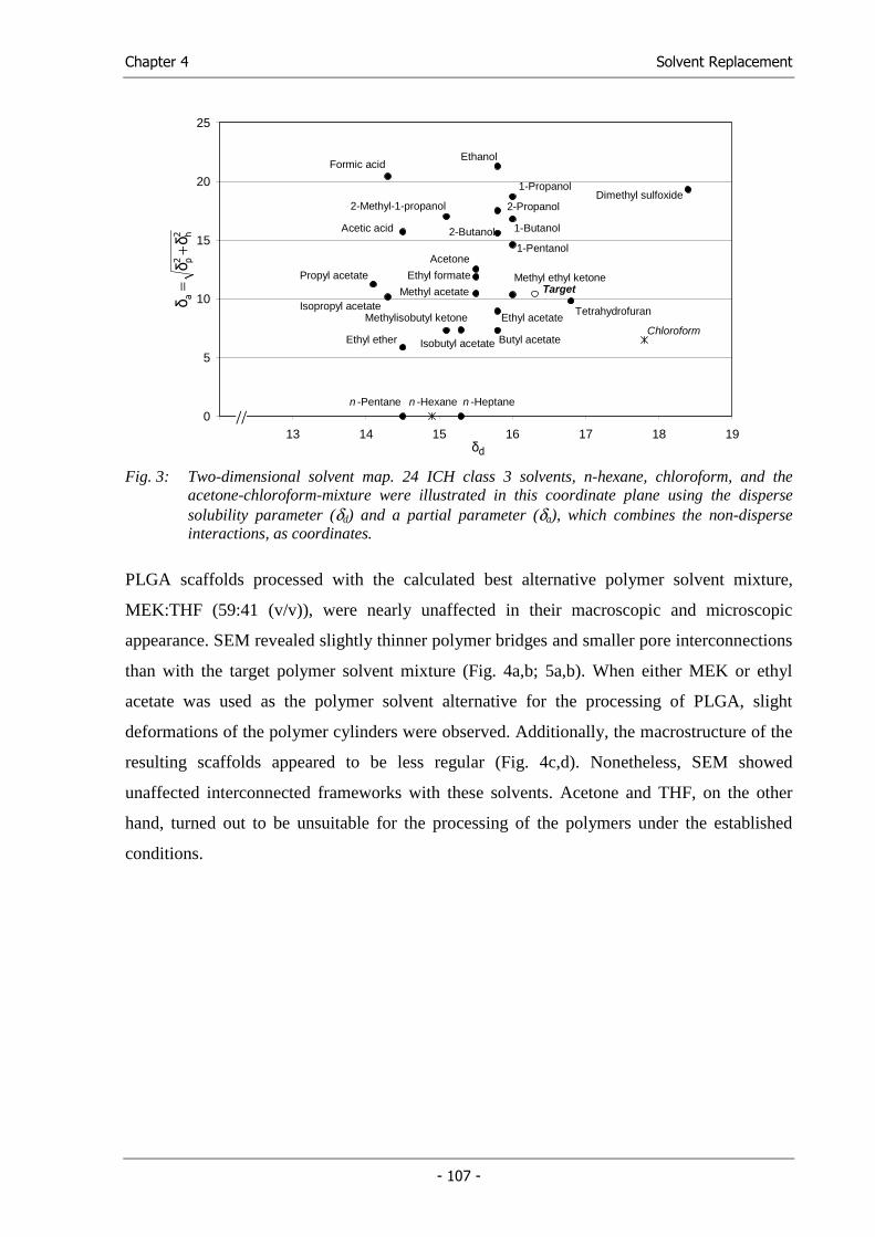
Chapter 4 Solvent Replacement
- 107 -
0
5
10
15
20
25
12 13 14 15 16 17 18 19
Tetrahydrofuran
Propyl acetate
Formic acid
Acetic acid
Isopropyl acetate
Ethyl ether
n -Pentane n -Heptane
2-Methyl-1-propanolDimethyl sulfoxide
Methylisobutyl ketone
Butyl acetate
Methyl acetate
Ethyl formate
Acetone
Isobutyl acetate
Ethyl acetate
Methyl ethyl ketone
2-Butanol
2-Propanol
Ethanol
1-Pentanol
1-Butanol
1-Propanol
Chloroform
Target
n -Hexane
//
dδ
2 h2 p
aδ
δδ
+=
Fig. 3: Two-dimensional solvent map. 24 ICH class 3 solvents, n-hexane, chloroform, and the
acetone-chloroform-mixture were illustrated in this coordinate plane using the disperse solubility parameter (δd) and a partial parameter (δa), which combines the non-disperse interactions, as coordinates.
PLGA scaffolds processed with the calculated best alternative polymer solvent mixture,
MEK:THF (59:41 (v/v)), were nearly unaffected in their macroscopic and microscopic
appearance. SEM revealed slightly thinner polymer bridges and smaller pore interconnections
than with the target polymer solvent mixture (Fig. 4a,b; 5a,b). When either MEK or ethyl
acetate was used as the polymer solvent alternative for the processing of PLGA, slight
deformations of the polymer cylinders were observed. Additionally, the macrostructure of the
resulting scaffolds appeared to be less regular (Fig. 4c,d). Nonetheless, SEM showed
unaffected interconnected frameworks with these solvents. Acetone and THF, on the other
hand, turned out to be unsuitable for the processing of the polymers under the established
conditions.
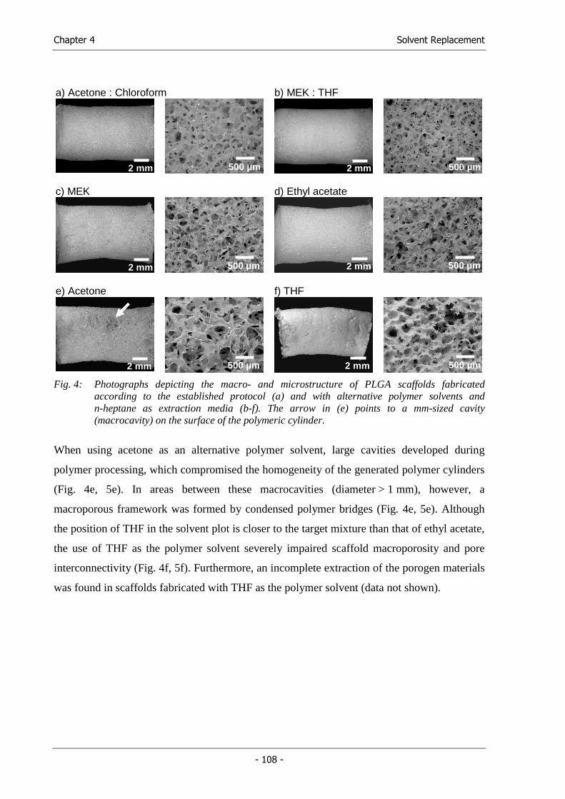
Chapter 4 Solvent Replacement
- 108 -
a) Acetone : Chloroform b) MEK : THF
c) MEK d) Ethyl acetate
e) Acetone f) THF
Fig. 4: Photographs depicting the macro- and microstructure of PLGA scaffolds fabricated according to the established protocol (a) and with alternative polymer solvents and n-heptane as extraction media (b-f). The arrow in (e) points to a mm-sized cavity (macrocavity) on the surface of the polymeric cylinder.
When using acetone as an alternative polymer solvent, large cavities developed during
polymer processing, which compromised the homogeneity of the generated polymer cylinders
(Fig. 4e, 5e). In areas between these macrocavities (diameter > 1 mm), however, a
macroporous framework was formed by condensed polymer bridges (Fig. 4e, 5e). Although
the position of THF in the solvent plot is closer to the target mixture than that of ethyl acetate,
the use of THF as the polymer solvent severely impaired scaffold macroporosity and pore
interconnectivity (Fig. 4f, 5f). Furthermore, an incomplete extraction of the porogen materials
was found in scaffolds fabricated with THF as the polymer solvent (data not shown).
2 mm
2 mm
2 mm
2 mm
2 mm
2 mm
500 µm
500 µm
500 µm
500 µm
500 µm
500 µm
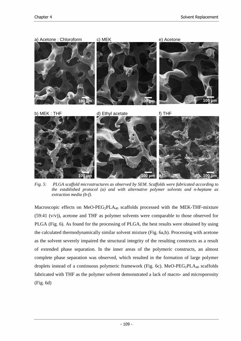
Chapter 4 Solvent Replacement
- 109 -
a) Acetone : Chloroform c) MEK e) Acetone
b) MEK : THF d) Ethyl acetate f) THF
Fig. 5: PLGA scaffold microstructures as observed by SEM. Scaffolds were fabricated according to
the established protocol (a) and with alternative polymer solvents and n-heptane as extraction media (b-f).
Macroscopic effects on MeO-PEG2PLA40 scaffolds processed with the MEK-THF-mixture
(59:41 (v/v)), acetone and THF as polymer solvents were comparable to those observed for
PLGA (Fig. 6). As found for the processing of PLGA, the best results were obtained by using
the calculated thermodynamically similar solvent mixture (Fig. 6a,b). Processing with acetone
as the solvent severely impaired the structural integrity of the resulting constructs as a result
of extended phase separation. In the inner areas of the polymeric constructs, an almost
complete phase separation was observed, which resulted in the formation of large polymer
droplets instead of a continuous polymeric framework (Fig. 6c). MeO-PEG2PLA40 scaffolds
fabricated with THF as the polymer solvent demonstrated a lack of macro- and microporosity
(Fig. 6d)
100 µm 100 µm 100 µm
100 µm 100 µm 100 µm
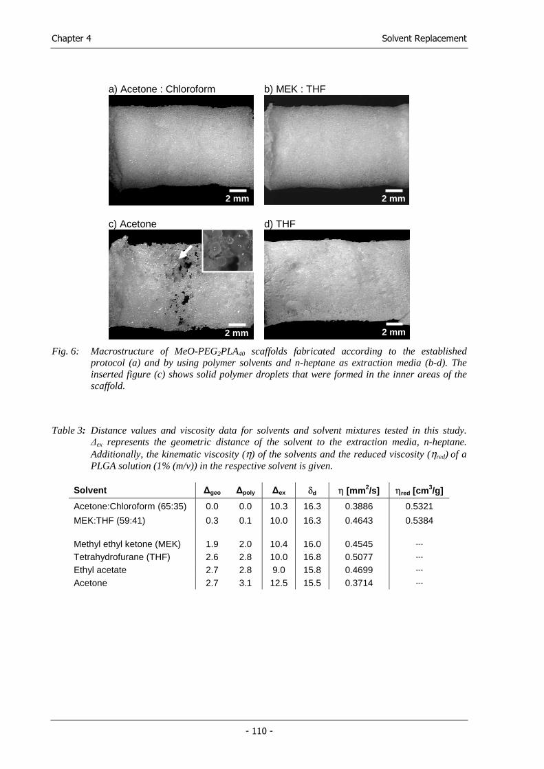
Chapter 4 Solvent Replacement
- 110 -
a) Acetone : Chloroform b) MEK : THF
c) Acetone d) THF
Fig. 6: Macrostructure of MeO-PEG2PLA40 scaffolds fabricated according to the established
protocol (a) and by using polymer solvents and n-heptane as extraction media (b-d). The inserted figure (c) shows solid polymer droplets that were formed in the inner areas of the scaffold.
Table 3: Distance values and viscosity data for solvents and solvent mixtures tested in this study. ∆ex represents the geometric distance of the solvent to the extraction media, n-heptane. Additionally, the kinematic viscosity (η) of the solvents and the reduced viscosity (ηred) of a PLGA solution (1% (m/v)) in the respective solvent is given.
Solvent ∆geo ∆poly ∆ex δd η [mm2/s] ηred [cm3/g]
Acetone:Chloroform (65:35) 0.0 0.0 10.3 16.3 0.3886 0.5321
MEK:THF (59:41) 0.3 0.1 10.0 16.3 0.4643 0.5384 Methyl ethyl ketone (MEK) 1.9 2.0 10.4 16.0 0.4545 ---
Tetrahydrofurane (THF) 2.6 2.8 10.0 16.8 0.5077 ---
Ethyl acetate 2.7 2.8 9.0 15.8 0.4699 ---
Acetone 2.7 3.1 12.5 15.5 0.3714 ---
2 mm 2 mm
2 mm 2 mm 2 mm
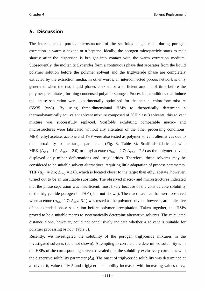
Chapter 4 Solvent Replacement
- 111 -
5. Discussion
The interconnected porous microstructure of the scaffolds is generated during porogen
extraction in warm n-hexane or n-heptane. Ideally, the porogen microparticle starts to melt
shortly after the dispersion is brought into contact with the warm extraction medium.
Subsequently, the molten triglycerides form a continuous phase that separates from the liquid
polymer solution before the polymer solvent and the triglyceride phase are completely
extracted by the extraction media. In other words, an interconnected porous network is only
generated when the two liquid phases coexist for a sufficient amount of time before the
polymer precipitates, forming condensed polymer sponges. Processing conditions that induce
this phase separation were experimentally optimized for the acetone-chloroform-mixture
(65:35 (v/v)). By using three-dimensional HSPs to theoretically determine a
thermodynamically equivalent solvent mixture composed of ICH class 3 solvents, this solvent
mixture was successfully replaced. Scaffolds exhibiting comparable macro- and
microstructures were fabricated without any alteration of the other processing conditions.
MEK, ethyl acetate, acetone and THF were also tested as polymer solvent alternatives due to
their proximity to the target parameters (Fig. 3, Table 3). Scaffolds fabricated with
MEK (∆geo = 1.9; ∆poly = 2.0) or ethyl acetate (∆geo = 2.7; ∆poly = 2.8) as the polymer solvent
displayed only minor deformations and irregularities. Therefore, these solvents may be
considered to be suitable solvent alternatives, requiring little adaptation of process parameters.
THF (∆geo = 2.6; ∆poly = 2.8), which is located closer to the target than ethyl acetate, however,
turned out to be an unsuitable substitute. The observed macro- and microstructures indicated
that the phase separation was insufficient, most likely because of the considerable solubility
of the triglyceride porogen in THF (data not shown). The macrocavities that were observed
when acetone (∆geo=2.7; ∆poly=3.1) was tested as the polymer solvent, however, are indicative
of an extended phase separation before polymer precipitation. Taken together, the HSPs
proved to be a suitable means to systematically determine alternative solvents. The calculated
distance alone, however, could not conclusively indicate whether a solvent is suitable for
polymer processing or not (Table 3).
Recently, we investigated the solubility of the porogen triglyceride mixtures in the
investigated solvents (data not shown). Attempting to correlate the determined solubility with
the HSPs of the corresponding solvent revealed that the solubility exclusively correlates with
the dispersive solubility parameter (δd). The onset of triglyceride solubility was determined at
a solvent δd value of 16.5 and triglyceride solubility increased with increasing values of δd.
Chapter 4 Solvent Replacement
- 112 -
Liao et al. measured the dissolution rates of PLGA particles in different solvents [29]. High
dissolution rates were found in chloroform (δd = 17.8) and dichloromethane (δd = 18.2). In
solvents with lower and higher values of δd, significantly lower dissolution rates were
measured. This data underlines the dominant influence of the solvent’s dispersive solubility
parameter on polymer and triglyceride solubility. With regard to δd, the solvents tested in this
study are ranked as follows: δd (acetone) < δd (ethyl acetate) < δd (MEK) < δd (MEK:THF) =
δd (acetone:chloroform) < 16.5 < δd (THF). This ranking correlates with the observed solvent
effects on scaffold macro- and microstructure. THF (δd > 16.5) was unsuitable for scaffold
fabrication most likely due to mixing with the molten triglyceride phase. Conversely, acetone
(δd = 15.5) did not mix with the triglyceride phase, but due to its high ∆ex (Table 3), the
geometric distance to the parameters of the extraction media n-heptane, polymer solvent
extraction was retarded, resulting in an extended demixing of polymer solution and
triglyceride phase and subsequent formation of large cavities and polymer droplets
(Fig. 4e, 5d). This effect was more pronounced when MeO-PEG2PLA40, a diblock copolymer
of PEG and PLA, was processed. Generally, the processing of this diblock copolymer was
more susceptible to parameter changes due to the polymer’s lower molecular weight and glass
transition temperature [12].
Based on these observations, the three-dimensional HSPs, and especially the partial parameter
δd, proved as useful means to compare solvents in terms of their suitability for the established
scaffold fabrication technique. Nevertheless, minor differences in microstructure between the
scaffolds fabricated with the acetone-chloroform-mixture (65:35 (v/v)) and the
thermodynamically similar MEK-THF-mixture (59:41 (v/v)) were observed. Since thinner
polymer bridges and smaller pore interconnections resulted from processing with the
MEK-THF-mixture, this structural difference likely resulted from polymer precipitation at an
earlier time point in the phase separation. As two thermodynamically similar solvent mixtures
are compared, the viscosity of the polymer solution is the remaining parameter that influences
the time point of polymer precipitation. Consequently, we determined the kinematic
viscosities of both solvent mixtures and the reduced viscosities of PLGA (1% (m/v)) solutions
in both solvent mixtures (Table 3). According to the solubility parameter theory, we obtained
comparable reduced viscosities for PLGA in both solvent mixtures. Substantial differences,
however, were found for the kinematic viscosities of the pure solvent mixtures. In other
words, a PLGA solution in the MEK-THF-mixture generally exhibits a higher viscosity than
an equally concentrated solution in the acetone-chloroform-mixture. Together with data
Chapter 4 Solvent Replacement
- 113 -
gathered during another study (chapter 6), this viscosity difference was identified as the
reason for the observed dissimilarity in scaffold microstructure.
In summary, solvents exhibiting HSPs similar to those of the acetone-chloroform-mixture
proved to be suitable for polymer processing into macroporous, interconnected scaffolds if
their dispersive solubility parameter value was smaller than 16.5. Additionally, the geometric
difference between the HSPs of the solvent and extraction media should not exceed a value of
10.5 (Table 3).
6. Conclusion
This study described the replacement of two ICH class 2 solvents from an established scaffold
fabrication procedure that makes use of two solvent dependant processes, namely solvent
extraction and phase separation, to generate interconnected pore structures. The HSPs of the
originally developed acetone-chloroform-mixture (65:35 (v/v)) were determined to
systematically search for a thermodynamically comparable solvent mixture composed of class
3 solvents using a geometric algorithm. A MEK-THF-mixture (59:41 (v/v)) resulted from this
search as suitable alternative. Scaffolds were fabricated using this mixture as the polymer
solvent, with n-heptane replacing n-hexane as the extraction media without any alteration of
other processing parameters. These results proved that three-dimensional HSPs are a useful
means to compare and replace solvents with regard to their thermodynamic properties in
biodegradable polymer processing. By illustrating the class 3 solvents in a two-dimensional
solubility parameter map, ethyl acetate and MEK were identified as further polymer solvent
alternatives. THF, which was also tested as solvent alternative, proved to not be suitable,
identifying the dispersive solubility parameter (δd) as the key parameter. Generally, this
solubility parameter based strategy holds great potential as a tool to replace halogenated
solvents from other polymeric release device fabrication procedures.
Chapter 4 Solvent Replacement
- 114 -
7. References
(1) Langer R, Folkman J. 'Polymers for the sustained release of proteins and other macromolecules'. Nature (1976); 263: 797-800.
(2) Brannon-Peppas L. 'Recent advances on the use of biodegradable microparticles and nanoparticles in controlled drug delivery'. Int J Pharm (1995); 116: 1-9.
(3) Langer R. 'Drug delivery and targeting'. Nature (1998); 392: 5-10.
(4) Langer R, Peppas NA. 'Advances in Biomaterials, Drug Delivery, and Bionanotechnology'. AIChE J (2003); 49: 2990-3006.
(5) Athanasiou KA, Agrawal CM, Barber FA, Burkhart SS. 'Orthopaedic applications for PLA-PGA biodegradable polymers'. Arthroscopy (1998); 14: 726-737.
(6) Freed LE, Vunjak NG, Biron RJ, Eagles DB, Lesnoy DC, Barlow SK, Langer R. 'Biodegradable polymer scaffolds for tissue engineering'. Biotechnology (N Y ) (1994); 12: 689-693.
(7) Baldwin SP, Mark Saltzman W. 'Materials for protein delivery in tissue engineering'. Adv Drug Delivery Rev (1998); 33: 71-86.
(8) Jain RA. 'The manufacturing techniques of various drug loaded biodegradable poly(lactide-co-glycolide) (PLGA) devices'. Biomaterials (2000); 21: 2475-2490.
(9) Agrawal CM, Ray RB. 'Biodegradable polymeric scaffolds for musculoskeletal tissue engineering'. J Biomed Mater Res (2001); 55: 141-150.
(10) Witschi C, Doelker E. 'Residual solvents in pharmaceutical products: acceptable limits, influences on physicochemical properties, analytical methods and documented values'. Eur J Pharm Biopharm (1997); 43: 215-242.
(11) International Conference on Harmonisation of technical requirements for registration of pharmaceuticals for human use. ICH harmonized Tripartite Guideline (Q3C) Impurities: Residual solvents. Draft 4 (1997). Available from http://www.ich.org
(12) Hacker M, Tessmar J, Neubauer M, Blaimer A, Blunk T, Gopferich A, Schulz MB. 'Towards biomimetic scaffolds: Anhydrous scaffold fabrication from biodegradable amine-reactive diblock copolymers'. Biomaterials (2003); 24: 4459-4473.
(13) Hildebrand JH, Scott RL. The Solubility of Non-Electrolytes. New York: Dover, 1964.
(14) Barton AFM. 'Solubility parameters'. Chem Rev (1975); 75: 731-754.
(15) Hansen CM. 'The universality of the solubility parameter concept'. Ind Eng Chem Prog Res Dev (1969); 8: 2-11.
(16) Hansen CM. 'Three-dimensional solubility parameter-key to paint-component affnities: I. Solvents, plasticizers, polymers, and resins'. J Paint Technol (1967); 39: 104-117.
Chapter 4 Solvent Replacement
- 115 -
(17) Hansen CM. 'Three-dimensional solubility parameter-key to paint component affinities. II. Dyes, emulsifiers, mutual solubility and compatibility, and pigments'. J Paint Technol (1967); 39: 505-510.
(18) Hansen CM, Skaarup K. 'Three-dimensional solubility parameter-key to paint component affinities. III. Independent calculation of the parameter components'. J Paint Technol (1967); 39: 511-514.
(19) Grulke EA. 'Solubility Parameter Values'. In: Brandrup J, Immergut EH, Grulke EA, editors. Polymer Handbook. New York: John Wiley, 1999. p. VII/675-714.
(20) Siemann U. 'The solubility parameter of poly(D,L-lactic acid)'. Eur Polym J (1992); 28: 293-297.
(21) Lindvig T, Michelsen ML, Kontogeorgis GM. 'A Flory-Huggins model based on the Hansen solubility parameters'. Fluid Phase Equilib (2002); 203: 247-260.
(22) Stoye D. 'Solvents'. In: Ullmann's Encycolpedia of Industrial Chemistry, Vol. A 24. Weinheim: VCH, 1993. p. 437-505.
(23) Segarceanu O, Leca M. 'Improved method to calculate Hansen solubility parameters of a polymer'. Prog Org Coat (1997); 31: 307-310.
(24) Gander B, Wehrli E, Alder R, Merkle HP. 'Quality improvement of spray-dried, protein-loaded D,L-PLA microspheres by appropriate polymer solvent selection'. J Microencapsul (1995); 12: 83-97.
(25) Gander B, Johansen P, Nam-Tran H, Merkle HP. 'Thermodynamic approach to protein microencapsulation into poly(D,L-lactide) by spray drying'. Int J Pharm (1996); 129: 51-61.
(26) Lucke A, Tessmar J, Schnell E, Schmeer G, Gopferich A. 'Biodegradable poly(,-lactic acid)-poly(ethylene glycol)-monomethyl ether diblock copolymers: structures and surface properties relevant to their use as biomaterials'. Biomaterials (2000); 21: 2361-2370.
(27) Tessmar JK, Mikos AG, Goepferich A. 'Amine-Reactive Biodegradable Diblock Copolymers'. Biomacromolecules (2002); 3: 194-200.
(28) Hansen, C. M. 'Three Dimensional Solubility Parameter and Solvent Diffusion Coefficient. Importance in Surface Coating Formulation.'. Doctoral Dissertation. Danish Technical Press, Copenhagen. (1967)
(29) Liao CJ, Chen CF, Chen JH, Chiang SF, Lin YJ, Chang KY. 'Fabrication of porous biodegradable polymer scaffolds using a solvent merging/particulate leaching method'. J Biomed Mater Res (2002); 59: 676-681.

Functional Cell Carriers for Tissue Engineering
Chapter 5
Solubility Parameters of Poly(lactic acid) and its Copolymers –
Theoretical and Experimental Considerations
Michael Hacker1, Andrea Blaimer1, Michaela B. Schulz1,2, Achim Göpferich1
1 Department of Pharmaceutical Technology, University of Regensburg,
Universitaetsstrasse 31, 93040 Regensburg, Germany 2 Department of Pharmaceutical Technology, University of Graz,
Schubertstrasse 6, 8010 Graz, Austria
Abstract
The three-dimensional Hansen solubility parameters (HSPs) of a polymer provide detailed
information on the thermodynamic properties of the molecule. Based on these parameters,
molecular interactions with solvents, other polymers, plasticizers, dyes and therapeutic
substances can be estimated. In this way, the HSPs are a means for the development and
optimization of polymer processing and drug encapsulation techniques. This study utilizes
both theoretical (group contribution method) and experimental (solubility measurements and
the determination of viscosity numbers) methods to determine the HSPs of poly(D,L-lactic
acid) (PLA) and copolymers with glycolic acid and poly(ethylene glycol). Different group
contribution data sets were compared and discussed. The absolute HSP values calculated by
this method appeared unrealistically high. On the basis of the solubility tests, a solvent map
was introduced to distinguish between solvents and non-solvents for the polymers. Detailed
information on the polymer-solvent interactions was obtained from the viscosity
measurements.
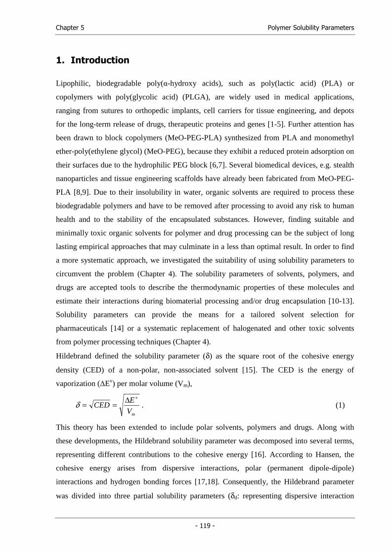
Chapter 5 Polymer Solubility Parameters
- 119 -
1. Introduction
Lipophilic, biodegradable poly(α-hydroxy acids), such as poly(lactic acid) (PLA) or
copolymers with poly(glycolic acid) (PLGA), are widely used in medical applications,
ranging from sutures to orthopedic implants, cell carriers for tissue engineering, and depots
for the long-term release of drugs, therapeutic proteins and genes [1-5]. Further attention has
been drawn to block copolymers (MeO-PEG-PLA) synthesized from PLA and monomethyl
ether-poly(ethylene glycol) (MeO-PEG), because they exhibit a reduced protein adsorption on
their surfaces due to the hydrophilic PEG block [6,7]. Several biomedical devices, e.g. stealth
nanoparticles and tissue engineering scaffolds have already been fabricated from MeO-PEG-
PLA [8,9]. Due to their insolubility in water, organic solvents are required to process these
biodegradable polymers and have to be removed after processing to avoid any risk to human
health and to the stability of the encapsulated substances. However, finding suitable and
minimally toxic organic solvents for polymer and drug processing can be the subject of long
lasting empirical approaches that may culminate in a less than optimal result. In order to find
a more systematic approach, we investigated the suitability of using solubility parameters to
circumvent the problem (Chapter 4). The solubility parameters of solvents, polymers, and
drugs are accepted tools to describe the thermodynamic properties of these molecules and
estimate their interactions during biomaterial processing and/or drug encapsulation [10-13].
Solubility parameters can provide the means for a tailored solvent selection for
pharmaceuticals [14] or a systematic replacement of halogenated and other toxic solvents
from polymer processing techniques (Chapter 4).
Hildebrand defined the solubility parameter (δ) as the square root of the cohesive energy
density (CED) of a non-polar, non-associated solvent [15]. The CED is the energy of
vaporization (∆Ev) per molar volume (Vm),
m
v
V
ECED
∆==δ . (1)
This theory has been extended to include polar solvents, polymers and drugs. Along with
these developments, the Hildebrand solubility parameter was decomposed into several terms,
representing different contributions to the cohesive energy [16]. According to Hansen, the
cohesive energy arises from dispersive interactions, polar (permanent dipole-dipole)
interactions and hydrogen bonding forces [17,18]. Consequently, the Hildebrand parameter
was divided into three partial solubility parameters (δd: representing dispersive interaction
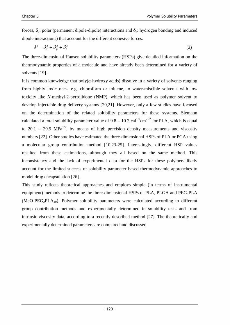
Chapter 5 Polymer Solubility Parameters
- 120 -
forces, δp: polar (permanent dipole-dipole) interactions and δh: hydrogen bonding and induced
dipole interactions) that account for the different cohesive forces:
2222hpd δδδδ ++= (2)
The three-dimensional Hansen solubility parameters (HSPs) give detailed information on the
thermodynamic properties of a molecule and have already been determined for a variety of
solvents [19].
It is common knowledge that poly(α-hydroxy acids) dissolve in a variety of solvents ranging
from highly toxic ones, e.g. chloroform or toluene, to water-miscible solvents with low
toxicity like N-methyl-2-pyrrolidone (NMP), which has been used as polymer solvent to
develop injectable drug delivery systems [20,21]. However, only a few studies have focused
on the determination of the related solubility parameters for these systems. Siemann
calculated a total solubility parameter value of 9.8 – 10.2 cal1/2cm-3/2 for PLA, which is equal
to 20.1 – 20.9 MPa1/2, by means of high precision density measurements and viscosity
numbers [22]. Other studies have estimated the three-dimensional HSPs of PLA or PGA using
a molecular group contribution method [10,23-25]. Interestingly, different HSP values
resulted from these estimations, although they all based on the same method. This
inconsistency and the lack of experimental data for the HSPs for these polymers likely
account for the limited success of solubility parameter based thermodynamic approaches to
model drug encapsulation [26].
This study reflects theoretical approaches and employs simple (in terms of instrumental
equipment) methods to determine the three-dimensional HSPs of PLA, PLGA and PEG-PLA
(MeO-PEG2PLA40). Polymer solubility parameters were calculated according to different
group contribution methods and experimentally determined in solubility tests and from
intrinsic viscosity data, according to a recently described method [27]. The theoretically and
experimentally determined parameters are compared and discussed.
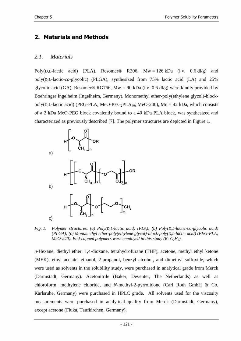
Chapter 5 Polymer Solubility Parameters
- 121 -
2. Materials and Methods
2.1. Materials
Poly(D,L-lactic acid) (PLA), Resomer® R206, Mw = 126 kDa (i.v. 0.6 dl/g) and
poly(D,L-lactic-co-glycolic) (PLGA), synthesized from 75% lactic acid (LA) and 25%
glycolic acid (GA), Resomer® RG756, Mw = 90 kDa (i.v. 0.6 dl/g) were kindly provided by
Boehringer Ingelheim (Ingelheim, Germany). Monomethyl ether-poly(ethylene glycol)-block-
poly(D,L-lactic acid) (PEG-PLA; MeO-PEG2PLA40; MeO-240), Mn = 42 kDa, which consists
of a 2 kDa MeO-PEG block covalently bound to a 40 kDa PLA block, was synthesized and
characterized as previously described [7]. The polymer structures are depicted in Figure 1.
a)
HO
O
CH3
OR
n
b)
HO
O
CH3
O
O
OR
x
n
y
c)
CH3HO
O
O
O
CH3m
n
Fig. 1: Polymer structures. (a) Poly(D,L-lactic acid) (PLA); (b) Poly(D,L-lactic-co-glycolic acid) (PLGA); (c) Monomethyl ether-poly(ethylene glycol)-block-poly(D,L-lactic acid) (PEG-PLA; MeO-240). End-capped polymers were employed in this study (R: C2H5).
n-Hexane, diethyl ether, 1,4-dioxane, tetrahydrofurane (THF), acetone, methyl ethyl ketone
(MEK), ethyl acetate, ethanol, 2-propanol, benzyl alcohol, and dimethyl sulfoxide, which
were used as solvents in the solubility study, were purchased in analytical grade from Merck
(Darmstadt, Germany). Acetonitrile (Baker, Deventer, The Netherlands) as well as
chloroform, methylene chloride, and N-methyl-2-pyrrolidone (Carl Roth GmbH & Co,
Karlsruhe, Germany) were purchased in HPLC grade. All solvents used for the viscosity
measurements were purchased in analytical quality from Merck (Darmstadt, Germany),
except acetone (Fluka, Taufkirchen, Germany).
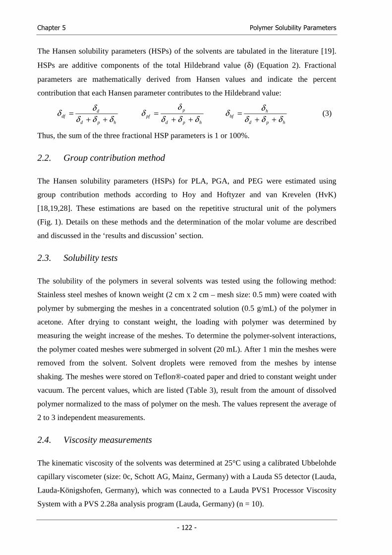
Chapter 5 Polymer Solubility Parameters
- 122 -
The Hansen solubility parameters (HSPs) of the solvents are tabulated in the literature [19].
HSPs are additive components of the total Hildebrand value (δ) (Equation 2). Fractional
parameters are mathematically derived from Hansen values and indicate the percent
contribution that each Hansen parameter contributes to the Hildebrand value:
hpd
ddf δδδ
δδ++
= hpd
ppf δδδ
δδ
++=
hpd
hhf δδδ
δδ++
= (3)
Thus, the sum of the three fractional HSP parameters is 1 or 100%.
2.2. Group contribution method
The Hansen solubility parameters (HSPs) for PLA, PGA, and PEG were estimated using
group contribution methods according to Hoy and Hoftyzer and van Krevelen (HvK)
[18,19,28]. These estimations are based on the repetitive structural unit of the polymers
(Fig. 1). Details on these methods and the determination of the molar volume are described
and discussed in the ‘results and discussion’ section.
2.3. Solubility tests
The solubility of the polymers in several solvents was tested using the following method:
Stainless steel meshes of known weight (2 cm x 2 cm – mesh size: 0.5 mm) were coated with
polymer by submerging the meshes in a concentrated solution (0.5 g/mL) of the polymer in
acetone. After drying to constant weight, the loading with polymer was determined by
measuring the weight increase of the meshes. To determine the polymer-solvent interactions,
the polymer coated meshes were submerged in solvent (20 mL). After 1 min the meshes were
removed from the solvent. Solvent droplets were removed from the meshes by intense
shaking. The meshes were stored on Teflon®-coated paper and dried to constant weight under
vacuum. The percent values, which are listed (Table 3), result from the amount of dissolved
polymer normalized to the mass of polymer on the mesh. The values represent the average of
2 to 3 independent measurements.
2.4. Viscosity measurements
The kinematic viscosity of the solvents was determined at 25°C using a calibrated Ubbelohde
capillary viscometer (size: 0c, Schott AG, Mainz, Germany) with a Lauda S5 detector (Lauda,
Lauda-Königshofen, Germany), which was connected to a Lauda PVS1 Processor Viscosity
System with a PVS 2.28a analysis program (Lauda, Germany) (n = 10).
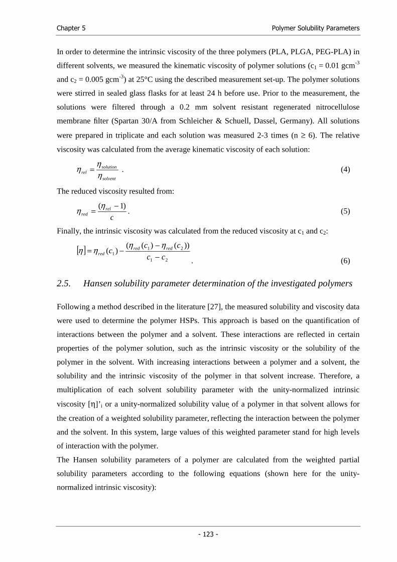
Chapter 5 Polymer Solubility Parameters
- 123 -
In order to determine the intrinsic viscosity of the three polymers (PLA, PLGA, PEG-PLA) in
different solvents, we measured the kinematic viscosity of polymer solutions (c1 = 0.01 gcm-3
and c2 = 0.005 gcm-3) at 25°C using the described measurement set-up. The polymer solutions
were stirred in sealed glass flasks for at least 24 h before use. Prior to the measurement, the
solutions were filtered through a 0.2 mm solvent resistant regenerated nitrocellulose
membrane filter (Spartan 30/A from Schleicher & Schuell, Dassel, Germany). All solutions
were prepared in triplicate and each solution was measured 2-3 times (n ≥ 6). The relative
viscosity was calculated from the average kinematic viscosity of each solution:
solvent
solutionrel η
ηη = . (4)
The reduced viscosity resulted from:
c
relred
)1( −=
ηη . (5)
Finally, the intrinsic viscosity was calculated from the reduced viscosity at c1 and c2:
[ ]
21
211
))()(()(
cc
ccc redred
red −−
−=ηηηη
. (6)
2.5. Hansen solubility parameter determination of the investigated polymers
Following a method described in the literature [27], the measured solubility and viscosity data
were used to determine the polymer HSPs. This approach is based on the quantification of
interactions between the polymer and a solvent. These interactions are reflected in certain
properties of the polymer solution, such as the intrinsic viscosity or the solubility of the
polymer in the solvent. With increasing interactions between a polymer and a solvent, the
solubility and the intrinsic viscosity of the polymer in that solvent increase. Therefore, a
multiplication of each solvent solubility parameter with the unity-normalized intrinsic
viscosity [η]’i or a unity-normalized solubility value of a polymer in that solvent allows for
the creation of a weighted solubility parameter, reflecting the interaction between the polymer
and the solvent. In this system, large values of this weighted parameter stand for high levels
of interaction with the polymer.
The Hansen solubility parameters of a polymer are calculated from the weighted partial
solubility parameters according to the following equations (shown here for the unity-
normalized intrinsic viscosity):
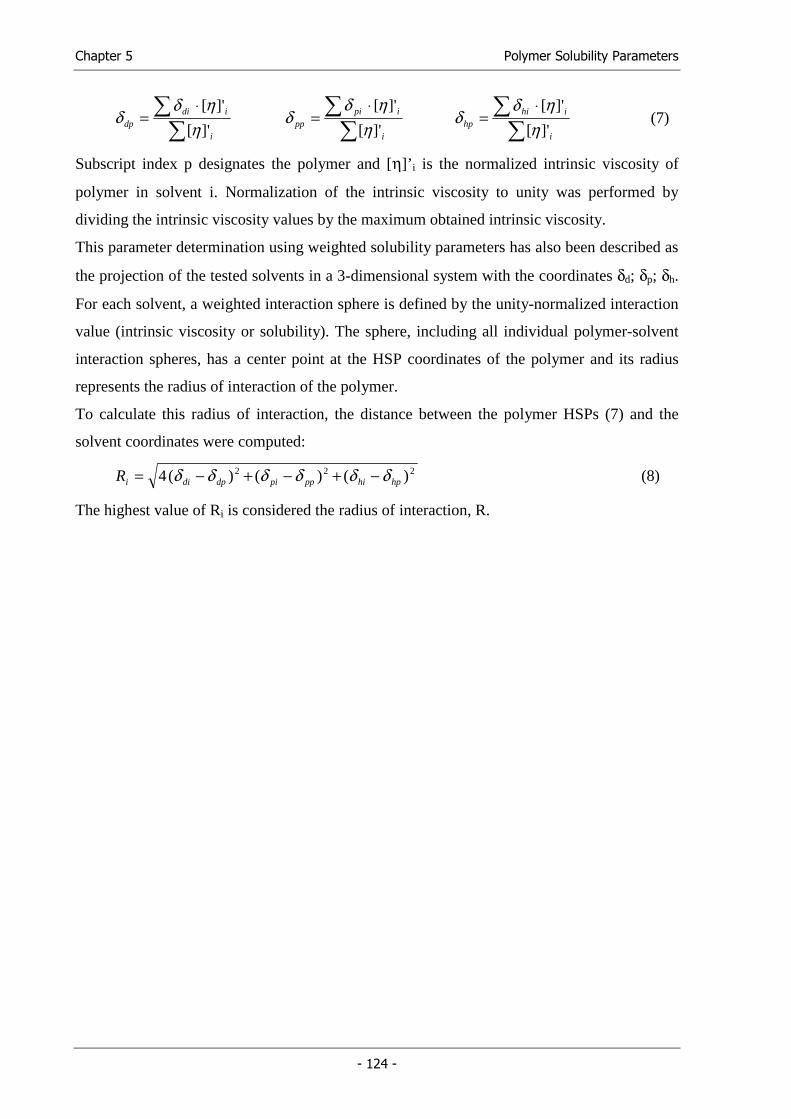
Chapter 5 Polymer Solubility Parameters
- 124 -
∑
∑ ⋅=
i
ididp ]'[
]'[
ηηδ
δ ∑
∑ ⋅=
i
ipipp ]'[
]'[
ηηδ
δ ∑
∑ ⋅=
i
ihihp ]'[
]'[
ηηδ
δ (7)
Subscript index p designates the polymer and [η]’i is the normalized intrinsic viscosity of
polymer in solvent i. Normalization of the intrinsic viscosity to unity was performed by
dividing the intrinsic viscosity values by the maximum obtained intrinsic viscosity.
This parameter determination using weighted solubility parameters has also been described as
the projection of the tested solvents in a 3-dimensional system with the coordinates δd; δp; δh.
For each solvent, a weighted interaction sphere is defined by the unity-normalized interaction
value (intrinsic viscosity or solubility). The sphere, including all individual polymer-solvent
interaction spheres, has a center point at the HSP coordinates of the polymer and its radius
represents the radius of interaction of the polymer.
To calculate this radius of interaction, the distance between the polymer HSPs (7) and the
solvent coordinates were computed:
222 )()()(4 hphipppidpdiiR δδδδδδ −+−+−= (8)
The highest value of Ri is considered the radius of interaction, R.
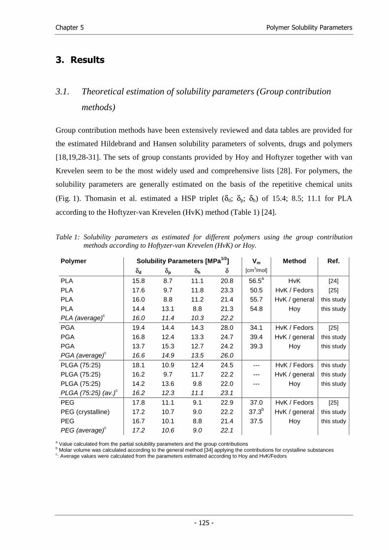
Chapter 5 Polymer Solubility Parameters
- 125 -
3. Results
3.1. Theoretical estimation of solubility parameters (Group contribution
methods)
Group contribution methods have been extensively reviewed and data tables are provided for
the estimated Hildebrand and Hansen solubility parameters of solvents, drugs and polymers
[18,19,28-31]. The sets of group constants provided by Hoy and Hoftyzer together with van
Krevelen seem to be the most widely used and comprehensive lists [28]. For polymers, the
solubility parameters are generally estimated on the basis of the repetitive chemical units
(Fig. 1). Thomasin et al. estimated a HSP triplet (δd; δp; δh) of 15.4; 8.5; 11.1 for PLA
according to the Hoftyzer-van Krevelen (HvK) method (Table 1) [24].
Table 1: Solubility parameters as estimated for different polymers using the group contribution methods according to Hoftyzer-van Krevelen (HvK) or Hoy.
Polymer Solubility Parameters [MPa1/2] Vm Method Ref. δd δp δh δ [cm3/mol]
PLA 15.8 8.7 11.1 20.8 56.5a HvK [24]
PLA 17.6 9.7 11.8 23.3 50.5 HvK / Fedors [25]
PLA 16.0 8.8 11.2 21.4 55.7 HvK / general this study
PLA 14.4 13.1 8.8 21.3 54.8 Hoy this study
PLA (average)c 16.0 11.4 10.3 22.2
PGA 19.4 14.4 14.3 28.0 34.1 HvK / Fedors [25]
PGA 16.8 12.4 13.3 24.7 39.4 HvK / general this study
PGA 13.7 15.3 12.7 24.2 39.3 Hoy this study
PGA (average)c 16.6 14.9 13.5 26.0
PLGA (75:25) 18.1 10.9 12.4 24.5 --- HvK / Fedors this study
PLGA (75:25) 16.2 9.7 11.7 22.2 --- HvK / general this study
PLGA (75:25) 14.2 13.6 9.8 22.0 --- Hoy this study
PLGA (75:25) (av.)c 16.2 12.3 11.1 23.1
PEG 17.8 11.1 9.1 22.9 37.0 HvK / Fedors [25]
PEG (crystalline) 17.2 10.7 9.0 22.2 37.3b HvK / general this study
PEG 16.7 10.1 8.8 21.4 37.5 Hoy this study
PEG (average)c 17.2 10.6 9.0 22.1
a Value calculated from the partial solubility parameters and the group contributions b Molar volume was calculated according to the general method [34] applying the contributions for crystalline substances c: Average values were calculated from the parameters estimated according to Hoy and HvK/Fedors
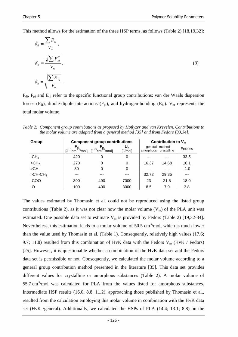
Chapter 5 Polymer Solubility Parameters
- 126 -
This method allows for the estimation of the three HSP terms, as follows (Table 2) [18,19,32]:
m
did V
F∑=δ ,
m
pi
p V
F∑=2
δ , (8)
m
hih V
E∑=δ .
Fdi, Fpi and Ehi refer to the specific functional group contributions: van der Waals dispersion
forces (Fdi), dipole-dipole interactions (Fpi), and hydrogen-bonding (Ehi). Vm represents the
total molar volume.
Table 2: Component group contributions as proposed by Hoftyzer and van Krevelen. Contributions to the molar volume are adapted from a general method [35] and from Fedors [33,34].
Group Component group contributions Contribution to Vm
Fd [J1/2cm3/2/mol]
Fp [J1/2cm3/2/mol]
Uh [J/mol]
general amorphous
method crystalline Fedors
-CH3 420 0 0 --- --- 33.5
>CH2 270 0 0 16.37 14.68 16.1 >CH- 80 0 0 --- --- -1.0 >CH-CH3 --- --- --- 32.72 29.35 ---
-COO- 390 490 7000 23 21.5 18.0
-O- 100 400 3000 8.5 7.9 3.8
The values estimated by Thomasin et al. could not be reproduced using the listed group
contributions (Table 2), as it was not clear how the molar volume (Vm) of the PLA unit was
estimated. One possible data set to estimate Vm is provided by Fedors (Table 2) [19,32-34].
Nevertheless, this estimation leads to a molar volume of 50.5 cm3/mol, which is much lower
than the value used by Thomasin et al. (Table 1). Consequently, relatively high values (17.6;
9.7; 11.8) resulted from this combination of HvK data with the Fedors Vm (HvK / Fedors)
[25]. However, it is questionable whether a combination of the HvK data set and the Fedors
data set is permissible or not. Consequently, we calculated the molar volume according to a
general group contribution method presented in the literature [35]. This data set provides
different values for crystalline or amorphous substances (Table 2). A molar volume of
55.7 cm3/mol was calculated for PLA from the values listed for amorphous substances.
Intermediate HSP results (16.0; 8.8; 11.2), approaching those published by Thomasin et al.,
resulted from the calculation employing this molar volume in combination with the HvK data
set (HvK /general). Additionally, we calculated the HSPs of PLA (14.4; 13.1; 8.8) on the
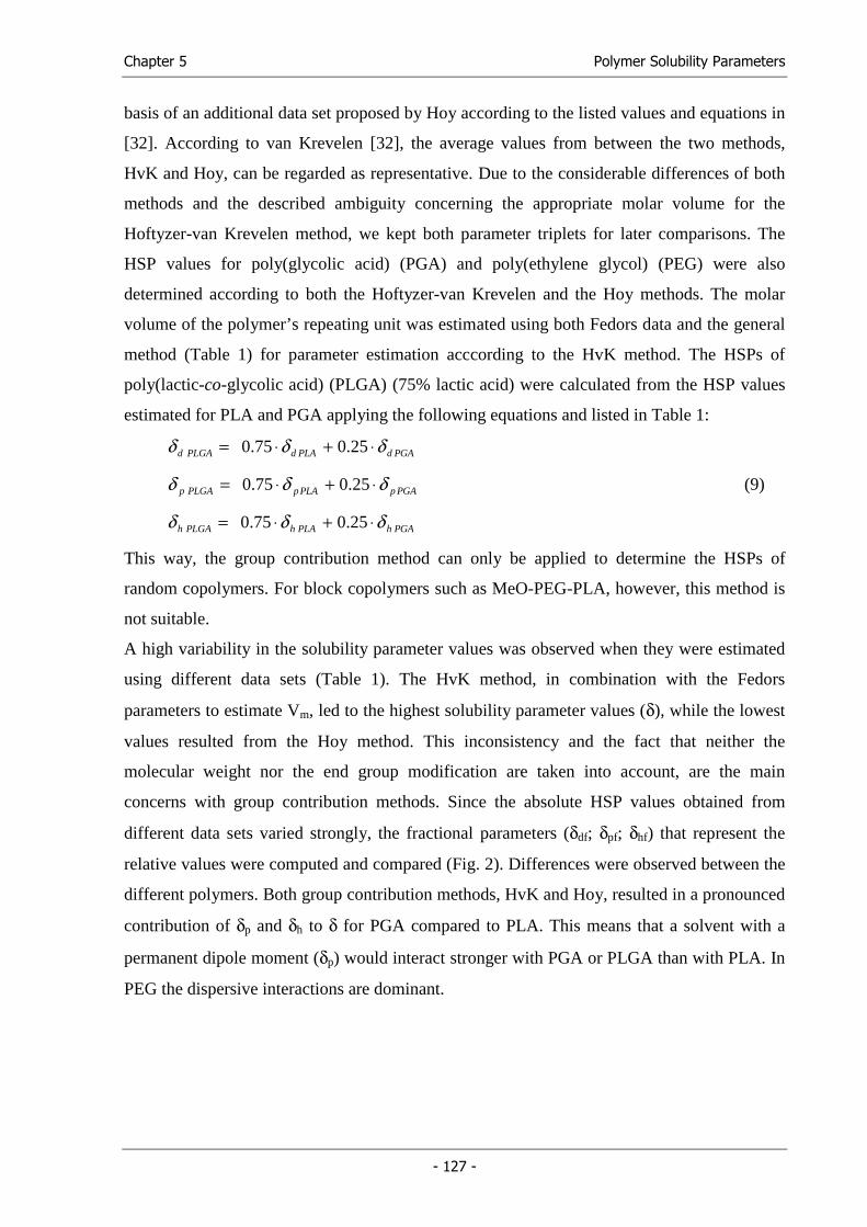
Chapter 5 Polymer Solubility Parameters
- 127 -
basis of an additional data set proposed by Hoy according to the listed values and equations in
[32]. According to van Krevelen [32], the average values from between the two methods,
HvK and Hoy, can be regarded as representative. Due to the considerable differences of both
methods and the described ambiguity concerning the appropriate molar volume for the
Hoftyzer-van Krevelen method, we kept both parameter triplets for later comparisons. The
HSP values for poly(glycolic acid) (PGA) and poly(ethylene glycol) (PEG) were also
determined according to both the Hoftyzer-van Krevelen and the Hoy methods. The molar
volume of the polymer’s repeating unit was estimated using both Fedors data and the general
method (Table 1) for parameter estimation acccording to the HvK method. The HSPs of
poly(lactic-co-glycolic acid) (PLGA) (75% lactic acid) were calculated from the HSP values
estimated for PLA and PGA applying the following equations and listed in Table 1:
PGAdPLAdPLGAd δδδ ⋅+⋅= 25.075.0
PGApPLApPLGAp δδδ ⋅+⋅= 25.075.0 (9)
PGAhPLAhPLGAh δδδ ⋅+⋅= 25.075.0
This way, the group contribution method can only be applied to determine the HSPs of
random copolymers. For block copolymers such as MeO-PEG-PLA, however, this method is
not suitable.
A high variability in the solubility parameter values was observed when they were estimated
using different data sets (Table 1). The HvK method, in combination with the Fedors
parameters to estimate Vm, led to the highest solubility parameter values (δ), while the lowest
values resulted from the Hoy method. This inconsistency and the fact that neither the
molecular weight nor the end group modification are taken into account, are the main
concerns with group contribution methods. Since the absolute HSP values obtained from
different data sets varied strongly, the fractional parameters (δdf; δpf; δhf) that represent the
relative values were computed and compared (Fig. 2). Differences were observed between the
different polymers. Both group contribution methods, HvK and Hoy, resulted in a pronounced
contribution of δp and δh to δ for PGA compared to PLA. This means that a solvent with a
permanent dipole moment (δp) would interact stronger with PGA or PLGA than with PLA. In
PEG the dispersive interactions are dominant.
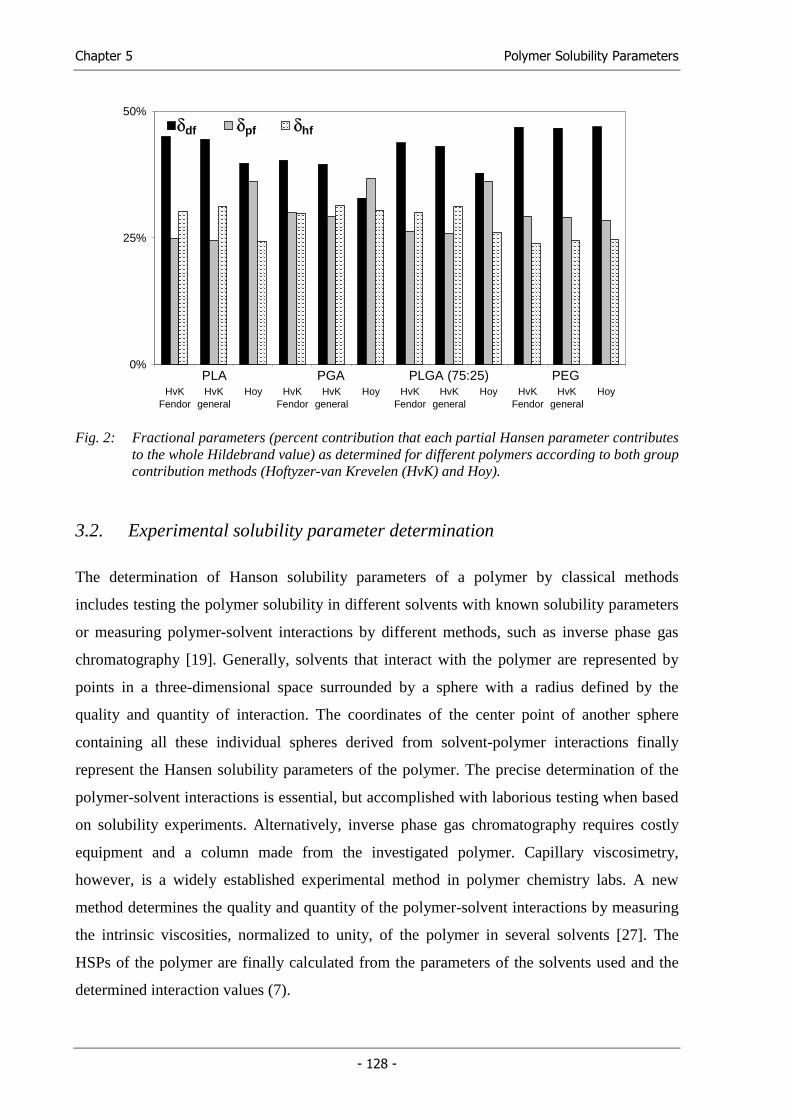
Chapter 5 Polymer Solubility Parameters
- 128 -
0%
25%
50%
PLAHvK
Fendor
PLAHvK
general
PLAHoy
PGAHvK
Fendor
PGAHvK
general
PGAHoy
PLGAHvK
Fendor
PLGAHvK
general
PLGAHoy
PEGHvK
Fendor
PEGHvK
general
PEGHoy
SPd SPp SPh
PLA PGA PLGA (75:25) PEG
δhf δpf δdf
Fig. 2: Fractional parameters (percent contribution that each partial Hansen parameter contributes
to the whole Hildebrand value) as determined for different polymers according to both group contribution methods (Hoftyzer-van Krevelen (HvK) and Hoy).
3.2. Experimental solubility parameter determination
The determination of Hanson solubility parameters of a polymer by classical methods
includes testing the polymer solubility in different solvents with known solubility parameters
or measuring polymer-solvent interactions by different methods, such as inverse phase gas
chromatography [19]. Generally, solvents that interact with the polymer are represented by
points in a three-dimensional space surrounded by a sphere with a radius defined by the
quality and quantity of interaction. The coordinates of the center point of another sphere
containing all these individual spheres derived from solvent-polymer interactions finally
represent the Hansen solubility parameters of the polymer. The precise determination of the
polymer-solvent interactions is essential, but accomplished with laborious testing when based
on solubility experiments. Alternatively, inverse phase gas chromatography requires costly
equipment and a column made from the investigated polymer. Capillary viscosimetry,
however, is a widely established experimental method in polymer chemistry labs. A new
method determines the quality and quantity of the polymer-solvent interactions by measuring
the intrinsic viscosities, normalized to unity, of the polymer in several solvents [27]. The
HSPs of the polymer are finally calculated from the parameters of the solvents used and the
determined interaction values (7).
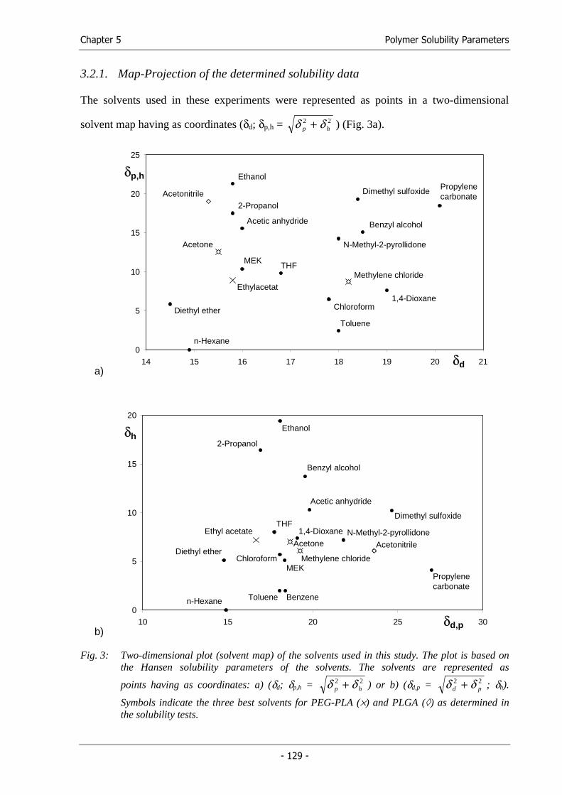
Chapter 5 Polymer Solubility Parameters
- 129 -
3.2.1. Map-Projection of the determined solubility data
The solvents used in these experiments were represented as points in a two-dimensional
solvent map having as coordinates (δd; δp,h = 22hp δδ + ) (Fig. 3a).
a)
0
5
10
15
20
25
14 15 16 17 18 19 20 21
THF
Acetic anhydride
Diethyl ether
2-Propanol
Dimethyl sulfoxide
Acetone
Ethylacetat
MEK
Ethanol
Chloroform
Methylene chloride
Toluene
1,4-Dioxane
Benzyl alcohol
Acetonitrile
N-Methyl-2-pyrollidone
n-Hexane
Propylenecarbonate
δp,h
δd
b)
0
5
10
15
20
10 15 20 25 30
THF
Acetic anhydride
Diethyl ether
2-Propanol
Dimethyl sulfoxide
Acetone
Ethyl acetate
MEK
Ethanol
Chloroform Methylene chloride
Toluene
1,4-Dioxane
Benzyl alcohol
Acetonitrile
N-Methyl-2-pyrollidone
n-Hexane
Propylenecarbonate
δh
δd,p
Benzene
Fig. 3: Two-dimensional plot (solvent map) of the solvents used in this study. The plot is based on the Hansen solubility parameters of the solvents. The solvents are represented as
points having as coordinates: a) (δd; δp,h = 22hp δδ + ) or b) (δd,p = 22
pd δδ + ; δh).
Symbols indicate the three best solvents for PEG-PLA (×) and PLGA (◊) as determined in the solubility tests.
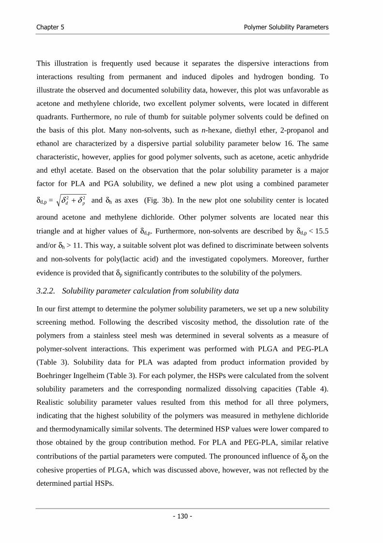
Chapter 5 Polymer Solubility Parameters
- 130 -
This illustration is frequently used because it separates the dispersive interactions from
interactions resulting from permanent and induced dipoles and hydrogen bonding. To
illustrate the observed and documented solubility data, however, this plot was unfavorable as
acetone and methylene chloride, two excellent polymer solvents, were located in different
quadrants. Furthermore, no rule of thumb for suitable polymer solvents could be defined on
the basis of this plot. Many non-solvents, such as n-hexane, diethyl ether, 2-propanol and
ethanol are characterized by a dispersive partial solubility parameter below 16. The same
characteristic, however, applies for good polymer solvents, such as acetone, acetic anhydride
and ethyl acetate. Based on the observation that the polar solubility parameter is a major
factor for PLA and PGA solubility, we defined a new plot using a combined parameter
δd,p = 22pd δδ + and δh as axes (Fig. 3b). In the new plot one solubility center is located
around acetone and methylene dichloride. Other polymer solvents are located near this
triangle and at higher values of δd,p. Furthermore, non-solvents are described by δd,p < 15.5
and/or δh > 11. This way, a suitable solvent plot was defined to discriminate between solvents
and non-solvents for poly(lactic acid) and the investigated copolymers. Moreover, further
evidence is provided that δp significantly contributes to the solubility of the polymers.
3.2.2. Solubility parameter calculation from solubility data
In our first attempt to determine the polymer solubility parameters, we set up a new solubility
screening method. Following the described viscosity method, the dissolution rate of the
polymers from a stainless steel mesh was determined in several solvents as a measure of
polymer-solvent interactions. This experiment was performed with PLGA and PEG-PLA
(Table 3). Solubility data for PLA was adapted from product information provided by
Boehringer Ingelheim (Table 3). For each polymer, the HSPs were calculated from the solvent
solubility parameters and the corresponding normalized dissolving capacities (Table 4).
Realistic solubility parameter values resulted from this method for all three polymers,
indicating that the highest solubility of the polymers was measured in methylene dichloride
and thermodynamically similar solvents. The determined HSP values were lower compared to
those obtained by the group contribution method. For PLA and PEG-PLA, similar relative
contributions of the partial parameters were computed. The pronounced influence of δp on the
cohesive properties of PLGA, which was discussed above, however, was not reflected by the
determined partial HSPs.
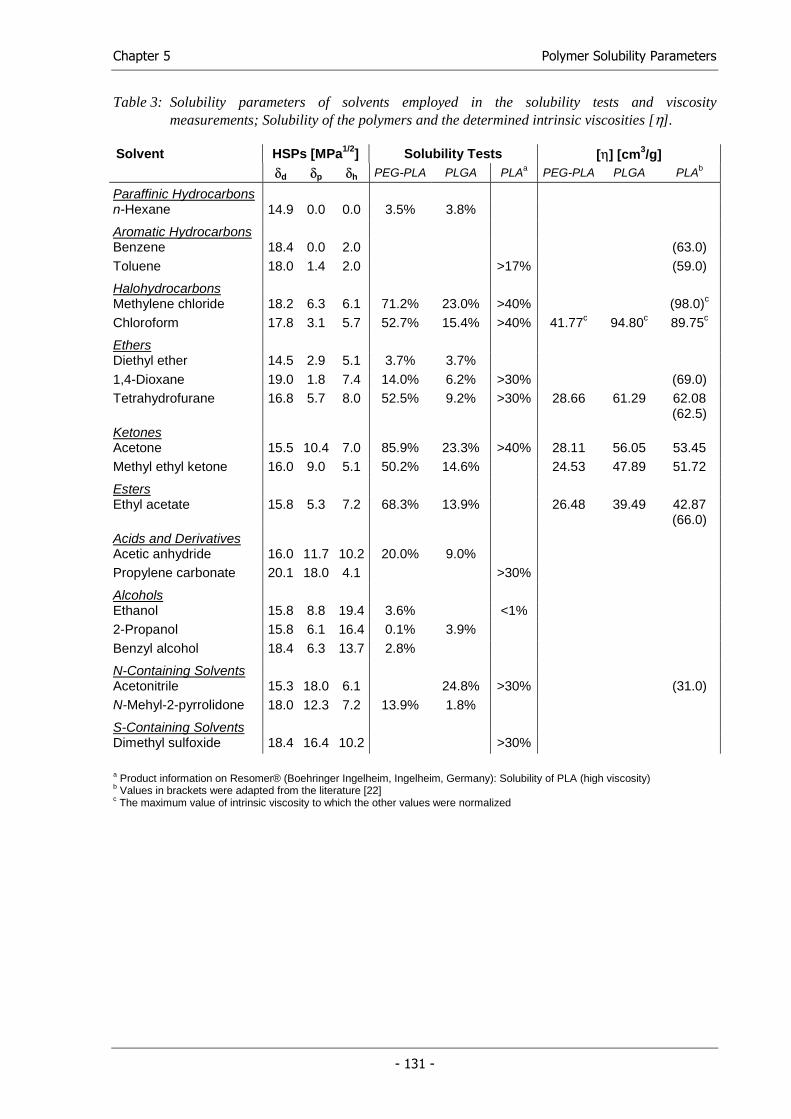
Chapter 5 Polymer Solubility Parameters
- 131 -
Table 3: Solubility parameters of solvents employed in the solubility tests and viscosity measurements; Solubility of the polymers and the determined intrinsic viscosities [η].
Solvent HSPs [MPa1/2] Solubility Tests [η] [cm3/g] δd δp δh PEG-PLA PLGA PLAa PEG-PLA PLGA PLAb
Paraffinic Hydrocarbons n-Hexane 14.9 0.0 0.0 3.5% 3.8%
Aromatic Hydrocarbons Benzene 18.4 0.0 2.0 (63.0) Toluene 18.0 1.4 2.0 >17% (59.0)
Halohydrocarbons Methylene chloride 18.2 6.3 6.1 71.2% 23.0% >40% (98.0)c
Chloroform 17.8 3.1 5.7 52.7% 15.4% >40% 41.77c 94.80c 89.75c
Ethers Diethyl ether 14.5 2.9 5.1 3.7% 3.7% 1,4-Dioxane 19.0 1.8 7.4 14.0% 6.2% >30% (69.0) Tetrahydrofurane 16.8 5.7 8.0 52.5% 9.2% >30% 28.66 61.29 62.08
(62.5) Ketones Acetone 15.5 10.4 7.0 85.9% 23.3% >40% 28.11 56.05 53.45 Methyl ethyl ketone 16.0 9.0 5.1 50.2% 14.6% 24.53 47.89 51.72
Esters Ethyl acetate 15.8 5.3 7.2 68.3% 13.9% 26.48 39.49 42.87
(66.0) Acids and Derivatives Acetic anhydride 16.0 11.7 10.2 20.0% 9.0% Propylene carbonate 20.1 18.0 4.1 >30%
Alcohols Ethanol 15.8 8.8 19.4 3.6% <1% 2-Propanol 15.8 6.1 16.4 0.1% 3.9% Benzyl alcohol 18.4 6.3 13.7 2.8%
N-Containing Solvents Acetonitrile 15.3 18.0 6.1 24.8% >30% (31.0) N-Mehyl-2-pyrrolidone 18.0 12.3 7.2 13.9% 1.8%
S-Containing Solvents Dimethyl sulfoxide 18.4 16.4 10.2 >30%
a Product information on Resomer® (Boehringer Ingelheim, Ingelheim, Germany): Solubility of PLA (high viscosity) b Values in brackets were adapted from the literature [22] c The maximum value of intrinsic viscosity to which the other values were normalized
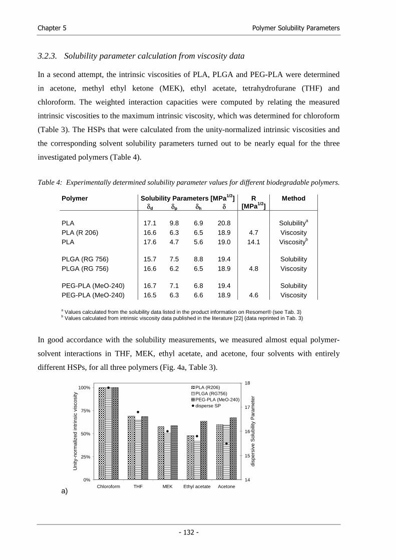
Chapter 5 Polymer Solubility Parameters
- 132 -
3.2.3. Solubility parameter calculation from viscosity data
In a second attempt, the intrinsic viscosities of PLA, PLGA and PEG-PLA were determined
in acetone, methyl ethyl ketone (MEK), ethyl acetate, tetrahydrofurane (THF) and
chloroform. The weighted interaction capacities were computed by relating the measured
intrinsic viscosities to the maximum intrinsic viscosity, which was determined for chloroform
(Table 3). The HSPs that were calculated from the unity-normalized intrinsic viscosities and
the corresponding solvent solubility parameters turned out to be nearly equal for the three
investigated polymers (Table 4).
Table 4: Experimentally determined solubility parameter values for different biodegradable polymers.
Polymer Solubility Parameters [MPa1/2] R Method δd δp δh δ [MPa1/2] PLA 17.1 9.8 6.9 20.8 Solubilitya PLA (R 206) 16.6 6.3 6.5 18.9 4.7 Viscosity PLA 17.6 4.7 5.6 19.0 14.1 Viscosityb
PLGA (RG 756) 15.7 7.5 8.8 19.4 Solubility PLGA (RG 756) 16.6 6.2 6.5 18.9 4.8 Viscosity PEG-PLA (MeO-240) 16.7 7.1 6.8 19.4 Solubility PEG-PLA (MeO-240) 16.5 6.3 6.6 18.9 4.6 Viscosity
a Values calculated from the solubility data listed in the product information on Resomer® (see Tab. 3) b Values calculated from intrinsic viscosity data published in the literature [22] (data reprinted in Tab. 3)
In good accordance with the solubility measurements, we measured almost equal polymer-
solvent interactions in THF, MEK, ethyl acetate, and acetone, four solvents with entirely
different HSPs, for all three polymers (Fig. 4a, Table 3).
a)
0%
25%
50%
75%
100%
Chloroform THF MEK Ethyl acetate Acetone
Uni
ty-n
orm
aliz
ed in
trin
sic
visc
osity
14
15
16
17
18
disp
ersi
ve S
olub
ility
Par
amet
er
PLA (R206)PLGA (RG756)PEG-PLA (MeO-240)disperse SP
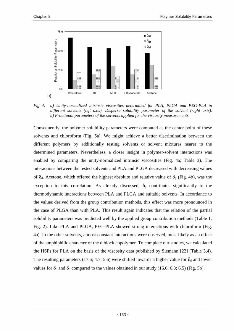
Chapter 5 Polymer Solubility Parameters
- 133 -
b)
0%
25%
50%
75%
Chloroform THF MEK Ethyl acetate Acetone
Fra
ctio
nal S
olub
ility
Par
amet
ers
SPd
SPp
SPh
δdδdδdf
δpf
δhf
Fig. 4: a) Unity-normalized intrinsic viscosities determined for PLA, PLGA and PEG-PLA in different solvents (left axis). Disperse solubility parameter of the solvent (right axis). b) Fractional parameters of the solvents applied for the viscosity measurements.
Consequently, the polymer solubility parameters were computed as the center point of these
solvents and chloroform (Fig. 5a). We might achieve a better discrimination between the
different polymers by additionally testing solvents or solvent mixtures nearer to the
determined parameters. Nevertheless, a closer insight in polymer-solvent interactions was
enabled by comparing the unity-normalized intrinsic viscosities (Fig. 4a; Table 3). The
interactions between the tested solvents and PLA and PLGA decreased with decreasing values
of δd. Acetone, which offered the highest absolute and relative value of δp (Fig. 4b), was the
exception to this correlation. As already discussed, δp contributes significantly to the
thermodynamic interactions between PLA and PLGA and suitable solvents. In accordance to
the values derived from the group contribution methods, this effect was more pronounced in
the case of PLGA than with PLA. This result again indicates that the relation of the partial
solubility parameters was predicted well by the applied group contribution methods (Table 1,
Fig. 2). Like PLA and PLGA, PEG-PLA showed strong interactions with chloroform (Fig.
4a). In the other solvents, almost constant interactions were observed, most likely as an effect
of the amphiphilic character of the diblock copolymer. To complete our studies, we calculated
the HSPs for PLA on the basis of the viscosity data published by Siemann [22] (Table 3,4).
The resulting parameters (17.6; 4.7; 5.6) were shifted towards a higher value for δd and lower
values for δp and δh compared to the values obtained in our study (16.6; 6.3; 6.5) (Fig. 5b).
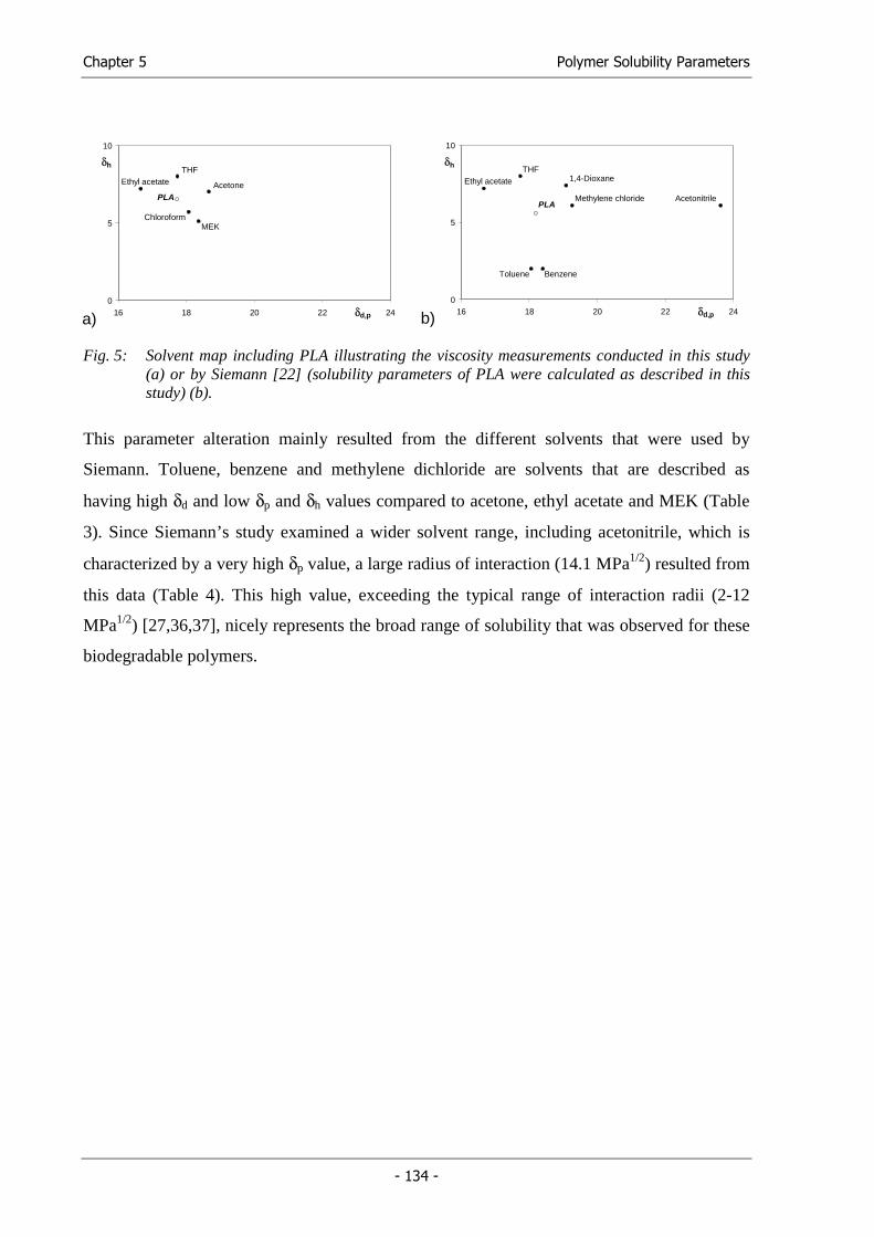
Chapter 5 Polymer Solubility Parameters
- 134 -
a)0
5
10
16 18 20 22 24
THF
AcetoneEthyl acetate
PLA
MEKChloroform
δh
δd,p b) 0
5
10
16 18 20 22 24
1,4-DioxaneTHF
Ethyl acetate
PLA AcetonitrileMethylene chloride
δh
δd,p
Toluene Benzene
Fig. 5: Solvent map including PLA illustrating the viscosity measurements conducted in this study (a) or by Siemann [22] (solubility parameters of PLA were calculated as described in this study) (b).
This parameter alteration mainly resulted from the different solvents that were used by
Siemann. Toluene, benzene and methylene dichloride are solvents that are described as
having high δd and low δp and δh values compared to acetone, ethyl acetate and MEK (Table
3). Since Siemann’s study examined a wider solvent range, including acetonitrile, which is
characterized by a very high δp value, a large radius of interaction (14.1 MPa1/2) resulted from
this data (Table 4). This high value, exceeding the typical range of interaction radii (2-12
MPa1/2) [27,36,37], nicely represents the broad range of solubility that was observed for these
biodegradable polymers.
Chapter 5 Polymer Solubility Parameters
- 135 -
4. Discussion
The solubility parameter estimations, solubility test and viscosity measurements revealed that
the solubility parameters of biodegradable poly(α-hydroxy acids) likely range near the values
of methylene dichloride and chloroform. The highest intrinsic viscosity, as a measure for the
interactions between solvent and polymer, was measured in chloroform for all of the tested
polymers. The solubility tests showed that methylene dichloride was the best solvent for the
polymers. Additional viscosity measurements might clarify whether methylene dichloride or
chloroform shows higher interactions with the polymers. The average HSP values of both
solvents are (δd; δp; δh = 18.0; 4.7; 5.9) resulting in a Hildebrand solubility parameter (δ) of
19.5, which is fairly close to the parameters calculated on the basis of the viscosity
measurements (δd; δp; δh = 16.6; 6.3; 6.5 and δ = 18.9) (Table 4). The group contribution
methods, however, led to much higher δp and δh values. Therefore, the experimentally
determined parameters are considered more precise to those estimated by the group
contribution methods.
In order to display the suitability of a solvent, it was important to not only focus on the HSP
triplet, but also to consider a combined partial parameter δd,p, resulting from δd and δp.
Acetone, for example, proved to be a good solvent for the investigated polymers, although
this solvent has a rather low δd, as is characteristic for most non-solvents (Table 3). However,
acetone has a high δp. Therefore, the combination of δd and δp to a combined partial parameter
δd,p versus δh seems to describe the solvent interactions with the polymers more precisely than
the δd versus the δp,h plot. Figure 3b illustrates that the polymers were soluble in solvents with
a δd,p exceeding 16 in combination with a δh smaller than 11. Only by introducing δd,p were
we able to describe solubility trends for the investigated polymers.
Generally, no significant differences between the different biodegradable polymers
investigated in this study were consistently evident across all of the methodologies. The
viscosity measurements, however, enabled a closer insight into polymer-solvent interactions.
Fig. 4a shows a decrease in the intrinsic viscosity of the solubilized polymers with decreasing
solvent δd values. However, this trend did not apply to acetone, probably due to the high δp
value of this solvent, highlighting the importance of the polar interactions. Moreover, with the
different solvents, we always found a lower unity-normalized intrinsic viscosity for PLGA
than for PLA (Fig. 4a). This did not hold true for acetone in accordance with the increased δp
values calculated by the group contribution methods. Accordingly, the group contribution
Chapter 5 Polymer Solubility Parameters
- 136 -
methods can be regarded as useful tools to estimate the fractional solubility parameters for the
investigated polymers. The fractional parameters highlight the ratio of the partial parameters
and allow for an easier comparison of the different solvents and polymers. The absolute HSP
values including those obtained by averaging the different methods, however, appeared too
high with regard to δp and δh (Table 1). Compared to the experimentally determined values,
the HSP computation performed according to the HvK method using the molar volumes
approximated according to the general method (HvK/general) fit best (Table 1).
Among the tested methods, the viscosity measurements were found to be most suitable to
investigate polymer-solvent interactions. As in many other methods, however, the resulting
HSPs depend on the parameter range of the investigated solvents (Fig. 5). In a similar manner,
the outstanding HSPs of propylene carbonate (20.1; 18.0; 4.1) influenced the HSPs of PLA
calculated from the solubility data provided by Boehringer Ingelheim. Based on this data set,
we determined a HSP triplet of (17.1; 9.8; 6.9) (Table 3); without propylene carbonate the
values (16.7; 8.8; 7.2) would have been closer to those resulting from the viscosity study.
Ideally, solvents near the borders of the solubility parameter maps should initially be included
in any study attempting to determine a polymer’s solubility parameters. Thereafter, solvents
located close to the determined center point of solubility should be tested for a precise
determination of the solubility parameter values.
5. Conclusion
Theoretical and experimental methods were applied to determine the Hansen solubility
parameters of PLA (Resomer® R206), PLGA (Resomer® RG 756) and PEG-PLA
(MeO-PEG2PLA40). HSPs computed according group contribution methods resulted in
artificially high absolute values for δp and δh. The fractional parameters predicted by these
methods, however, proved valuable. In solubility tests, the polymers demonstrated the best
solubility in solvents offering a δd,p from 17 to 20 and a δh between 5 and 8. These parameters
correlated well to the values calculated from the viscosity measurements. Although partial
solubility parameter discrimination between the investigated polymers was not achieved,
viscosity measurements provided detailed information on polymer-solvent interactions.
Chapter 5 Polymer Solubility Parameters
- 137 -
6. References
(1) Gombotz WR, Pettit DK. 'Biodegradable polymers for protein and peptide drug delivery'. Bioconjug Chem (1995); 6: 332-351.
(2) Langer R, Peppas NA. 'Advances in Biomaterials, Drug Delivery, and Bionanotechnology'. AIChE J (2003); 49: 2990-3006.
(3) Panyam J, Labhasetwar V. 'Biodegradable nanoparticles for drug and gene delivery to cells and tissue'. Adv Drug Delivery Rev (2003); 55: 329-347.
(4) Jain RA. 'The manufacturing techniques of various drug loaded biodegradable poly(lactide-co-glycolide) (PLGA) devices'. Biomaterials (2000); 21: 2475-2490.
(5) Athanasiou KA, Agrawal CM, Barber FA, Burkhart SS. 'Orthopaedic applications for PLA-PGA biodegradable polymers'. Arthroscopy (1998); 14: 726-737.
(6) Gopferich A, Peter SJ, Lucke A, Lu L, Mikos AG. 'Modulation of marrow stromal cell function using poly(D,L-lactic acid)-block-poly(ethylene glycol)-monomethyl ether surfaces'. J Biomed Mater Res (1999); 46: 390-398.
(7) Lucke A, Tessmar J, Schnell E, Schmeer G, Gopferich A. 'Biodegradable poly(,-lactic acid)-poly(ethylene glycol)-monomethyl ether diblock copolymers: structures and surface properties relevant to their use as biomaterials'. Biomaterials (2000); 21: 2361-2370.
(8) Gref R, Luck M, Quellec P, Marchand M, Dellacherie E, Harnisch S, Blunk T, Muller RH. ''Stealth' corona-core nanoparticles surface modified by polyethylene glycol (PEG): Influences of the corona (PEG chain length and surface density) and of the core composition on phagocytic uptake and plasma protein adsorption'. Colloids Surf B (2000); 18: 301-313.
(9) Hacker M, Tessmar J, Neubauer M, Blaimer A, Blunk T, Gopferich A, Schulz MB. 'Towards biomimetic scaffolds: Anhydrous scaffold fabrication from biodegradable amine-reactive diblock copolymers'. Biomaterials (2003); 24: 4459-4473.
(10) Thomasin C, Ho NT, Merkle HP, Gander B. 'Drug microencapsulation by PLA/PLGA coacervation in the light of thermodynamics. 1. Overview and theoretical considerations'. J Pharm Sci (1998); 87: 259-268.
(11) Forster A, Hempenstall J, Tucker I, Rades T. 'Selection of excipients for melt extrusion with two poorly water-soluble drugs by solubility parameter calculation and thermal analysis'. Int J Pharm (2001); 226: 147-161.
(12) Li J, Masso JJ, Guertin JA. 'Prediction of drug solubility in an acrylate adhesive based on the drug-polymer interaction parameter and drug solubility in acetonitrile'. J Control Release (2002); 83: 211-221.
(13) Hancock BC, York P, Rowe RC. 'The use of solubility parameters in pharmaceutical dosage form design'. Int J Pharm (1997); 148: 1-21.
Chapter 5 Polymer Solubility Parameters
- 138 -
(14) Kolar P, Shen JW, Tsuboi A, Ishikawa T. 'Solvent selection for pharmaceuticals'. Fluid Phase Equilib (2002); 194-197: 771-782.
(15) Hildebrand JH, Scott RL. The Solubility of Non-Electrolytes. New York: Dover, 1964.
(16) Barton AFM. 'Solubility parameters'. Chem Rev (1975); 75: 731-754.
(17) Hansen, C. M. 'Three Dimensional Solubility Parameter and Solvent Diffusion Coefficient. Importance in Surface Coating Formulation.'. Doctoral Dissertation. Danish Technical Press, Copenhagen. (1967)
(18) Barton AFM. CRC Handbook of Solubility Parameters and Other Cohesion Parameters. 1983.
(19) Grulke EA. 'Solubility Parameter Values'. In: Brandrup J, Immergut EH, Grulke EA, editors. Polymer Handbook. New York: John Wiley, 1999. p. VII/675-714.
(20) Shively ML, Coonts BA, Renner WD, Southard JL, Bennett AT. 'Physico-chemical characterization of a polymeric injectable implant delivery system'. J Control Release (1995); 33: 237-243.
(21) Packhaeuser CB, Schnieders J, Oster CG, Kissel T. 'In situ forming parenteral drug delivery systems: an overview'. Eur J Pharm Biopharm (2004); 58: 445-455.
(22) Siemann U. 'The solubility parameter of poly(D,L-lactic acid)'. Eur Polym J (1992); 28: 293-297.
(23) Gander B, Wehrli E, Alder R, Merkle HP. 'Quality improvement of spray-dried, protein-loaded D,L-PLA microspheres by appropriate polymer solvent selection'. J Microencapsul (1995); 12: 83-97.
(24) Thomasin C, Merkle HP, Gander B. 'Drug microencapsulation by PLA/PLGA coacervation in the light of thermodynamics. 2. Parameters determining microsphere formation'. J Pharm Sci (1998); 87: 269-275.
(25) Liu J, Xiao Y, Allen C. 'Polymer-Drug Compatibility: A Guide to the Development of Delivery Systems for the Anticancer Agent, Ellipticine'. J Pharm Sci (2004); 93: 132-143.
(26) Gander B, Johansen P, Nam-Tran H, Merkle HP. 'Thermodynamic approach to protein microencapsulation into poly(D,L-lactide) by spray drying'. Int J Pharm (1996); 129: 51-61.
(27) Segarceanu O, Leca M. 'Improved method to calculate Hansen solubility parameters of a polymer'. Prog Org Coat (1997); 31: 307-310.
(28) van Krevelen DW. Properties of Polymers. Amsterdam, The Netherlands: Elsevier, 1990.
(29) Ahmad H, Yaseen M. 'Application of a chemical group contribution technique for calculating solubility parameters of polymers'. Polym Eng Sci (1979); 19: 858-863.
Chapter 5 Polymer Solubility Parameters
- 139 -
(30) Bustamante P, Escalera B, Martin A, Selles E. 'Predicting the solubility of sulfamethoxypyridazine in individual solvents I: calculating partial solubility parameters'. J Pharm Sci (1989); 78: 567-573.
(31) Breitkreutz J. 'Prediction of intestinal drug absorption properties by three-dimensional solubility parameters'. Pharm Res (1998); 15: 1370-1375.
(32) van Krevelen DW. 'Chapter 7: Cohesive Properties and Solubility'. In: Properties of Polymers. Amsterdam, The Netherlands: Elsevier, 1990. p. 189-225.
(33) Fedors RF. 'Method for estimating both the solubility parameters and molar volumes of liquids'. Polym Eng Sci (1974); 14: 147-154.
(34) Fedors RF. 'Method for estimating both the solubility parameters and molar volumes of liquids. Addendum'. Polym Eng Sci (1974); 14: 472-
(35) van Krevelen DW. 'Chapter 4: Volumetric Properties'. In: Properties of Polymers. Amsterdam, The Netherlands: Elsevier, 1990. p. 71-107.
(36) Lindvig T, Michelsen ML, Kontogeorgis GM. 'A Flory-Huggins model based on the Hansen solubility parameters'. Fluid Phase Equilib (2002); 203: 247-260.
(37) Stoye D. 'Solvents'. In: Ullmann's Encycolpedia of Industrial Chemistry, Vol. A 24. Weinheim: VCH, 1993. p. 437-505.

Functional Cell Carriers for Tissue Engineering
Chapter 6
Solid Lipid Templating: A Versatile Lab-scale Fabrication Technique
for Macroporous Tissue Engineering Scaffolds
Michael Hacker1, Michael Ringhofer2, Markus Neubauer1, Thomas Vogel1,3,
Bernhard Appel1, Torsten Blunk1, Achim Göpferich1, Michaela B. Schulz1,3
1 Department of Pharmaceutical Technology, University of Regensburg,
Universiätsstrasse 31, 93040 Regensburg, Germany 2 Anton Paar GmbH, Anton Paar Strasse 20, 8054 Graz, Austria 3 Department of Pharmaceutical Technology, University of Graz,
Schubertstrasse 6, 8010 Graz, Austria
Tissue Engineering (to be submitted)

Chapter 6 Solid Lipid Templating
- 143 -
1. Introduction
The engineering of functional tissues from isolated mammalian cells and macroporous three-
dimensional (3-D) biomaterial constructs holds great potential for applications in the medical
and natural sciences [1-3]. A typical tissue engineering approach uses biocompatible,
biodegradable, polymeric cell carriers (scaffolds) as an artificial extracellular matrix in
combination with morphogenetic effectors (e.g. growth, differentiation and adhesion factors)
and host cells that will respond to the signals of the effector substance [4]. In these attempts,
the scaffolds play a pivotal role in cell seeding, proliferation, and new tissue formation in
three dimensions [5]. Biodegradable poly(α-hydroxy acids), namely poly(D,L-lactic acid)
(PLA) and copolymers (PLGA) with poly(glycolic acid) (PGA), are attractive and widely
applied scaffolding materials with advantages over ceramics and metals because they degrade
as the new tissues are formed [6,7]. In contrast to natural scaffolding materials, such as
collagen, chitosan or chitin, these synthetic polymers can be supplied in reproducible quality
and free of pathogenic or immunogenic organic residues. Depending on the mechanical
properties of the tissue to be engineered and the extent of cell-material interaction desired, a
suitable polymer has to be selected with regard to its degradation kinetic, composition and
molecular weight. Consequently, materials with different characteristics, such as molecular
weight, glass transition temperature and solubility, have to be processed into macroporous cell
carriers with reproducible microstructure. Various techniques such as salt leaching [8,9],
fibrous fabric processing [6], gas foaming [10], thermally induced phase separation [11] and
several solid freeform fabrication techniques [12] have been developed to generate highly
porous polymer scaffolds from biodegradable polymers. Despite the remarkable potential that
some of these scaffolds have shown in attempts to engineer a variety of tissues, the “ideal”
scaffold has not yet been developed [13,14]. The critical scaffold properties and demands on
the fabrication procedure are the following: Architectural features, namely pore size and
shape, pore wall morphology, porosity, surface area and pore interconnectivity, have to be
controlled, as they have a direct impact on cell seeding, migration, growth, transport of
oxygen, nutrients and wastes, and new tissue formation in three dimensions [15,16].
Therefore, control over architectural features, especially pore size and interconnectivity,
during scaffold fabrication is essential. Fibrous fabrics, for instance, offer the ideal porosity
and permeability. Their mechanical stability, however, is very low and only a few materials
can be processed into such scaffolds. Salt leaching, on the other hand, is a technique that
offers good control over the scaffold pore size and porosity. But even improved salt fusion
Chapter 6 Solid Lipid Templating
- 144 -
techniques result in scaffolds that lack sufficient pore interconnectivity [17,18]. The
applicability of the processing method to a variety of polymers and polymer properties, which
in large part predetermine the mechanical and degradation characteristics of a scaffold, is a
further prerequisite for an ideal processing method. As some applications use experimental
polymers that may contain hydrolysable functional groups [19] or require the encapsulation of
growth factors during scaffold fabrication, an anhydrous fabrication technique is generally
preferred. Moreover, lab-scale processing enables scaffold fabrication from small amounts of
newly developed biodegradables and allows for the systematic testing of different
architectural designs. Nevertheless, the fabrication should not be limited to a certain scaffold
size. A recently published hydrocarbon templating technique met most of the described
demands [20]. This technique was further improved with regard to biocompatibility and
adaptability to low molecular weight block copolymers by our group [21]. The developed
solid lipid templating technique uses solid lipid microparticles as porogens and non-
halogenated polymer solvents to process biodegradable polymers into macroporous scaffolds,
providing an interconnected pore structure. Pore interconnectivity is obtained by adjusting the
porogen melting point and extraction conditions to the polymer’s glass transition temperature.
This way, a continuous molten lipid phase is formed during porogen extraction in warm
n-hexane. Simultaneously, the polymer is precipitated at the phase boundary, leading to the
formation of condensed polymer sponges [21].
In this study, we demonstrate the wide applicability of this technique. Processing conditions
are described to fabricate tissue engineering scaffolds from several biodegradable polymers of
different compositions and molecular weights. The pore size of the scaffolds was controlled
by the size distribution of the porogen microparticles. During processing, the rheological
behavior of the dispersion prepared from the polymer solution and porogen microparticles has
major influence on micro- and microstructure of the resulting scaffolds. We observed that
highly viscous dispersions resulted in low interconnectivity, while a low viscosity caused
macroscopic deformation of the scaffold as well as coarsening of the microstructure. To
address this process parameter, oscillating rheological measurements were performed. Since
the viscosity of the dispersion also depends on the size of the particles of the solid phase, we
controlled the viscosity by increasing the polymer concentration with increasing porogen
particle size. The suitability of the fabricated scaffolds was tested using an established
cartilage cell culture model [22].
Chapter 6 Solid Lipid Templating
- 145 -
2. Materials and Methods
2.1. Materials
Poly(D,L-lactic acid) (PLA), Resomer® R207, Mw = 160 kDa, Tg = 54.8 °C, poly(D,L-lactic-
co-glycolic) (PLGA), Resomer® RG756, synthesized from 75% lactic acid (LA) and 25%
glycolic acid (GA), Mw = 90 kDa, Tg = 50.7 °C, were kindly provided by Boehringer
Ingelheim (Ingelheim, Germany). Monomethyl ether-poly(ethylene glycol)-block-poly(D,L-
lactic acid) (MeO-PEG2PLA40; MeO-240), Mn = 42 kDa, Tg = 43.0 °C, which consist of a 2
kDa MeO-PEG block covalently bound to a 40 kDa PLA block, was synthesized and
characterized as previously described [23].
The solid lipids that were used as porogen materials, namely Softisan® 154 and Witepsol®
H42, were kindly provided by SASOL Germany GmbH (Witten, Germany). Methyl ethyl
ketone (MEK), tetrahydrofurane (THF), ethyl acetate and n-hexane were purchased in
analytical grade from Merck (Darmstadt, Germany).
2.2. Methods
2.2.1. Preparation of solid lipid microparticles
Microparticles were prepared using a melt dispersion technique. 10 g of the solid lipid
mixture prepared from Softisan® 154 und Witepsol® H42 (SH), either SH 1:1 or SH 2:1,
were weighed in a poly(propylene) tube. After the addition of 7.5 mL water, the tube was
heated to 65 °C. In a normal batch, eight tubes were processed in parallel. The mixture was
emulsified by turning the tube upside down 10 times and subsequently cast into a larger
volume (600 mL) of stirred, cold (15 °C) water. After 10 min of constant stirring, the
hardened particles were collected by filtration, rinsed with cold water and dried under laminar
air flow for 3 days. Finally, the microparticles were separated into different size ranges by
sifting with sieves (100µm, 300µm, 500µm, 710µm) (Retsch GmbH & Co. KG, Haan,
Germany).
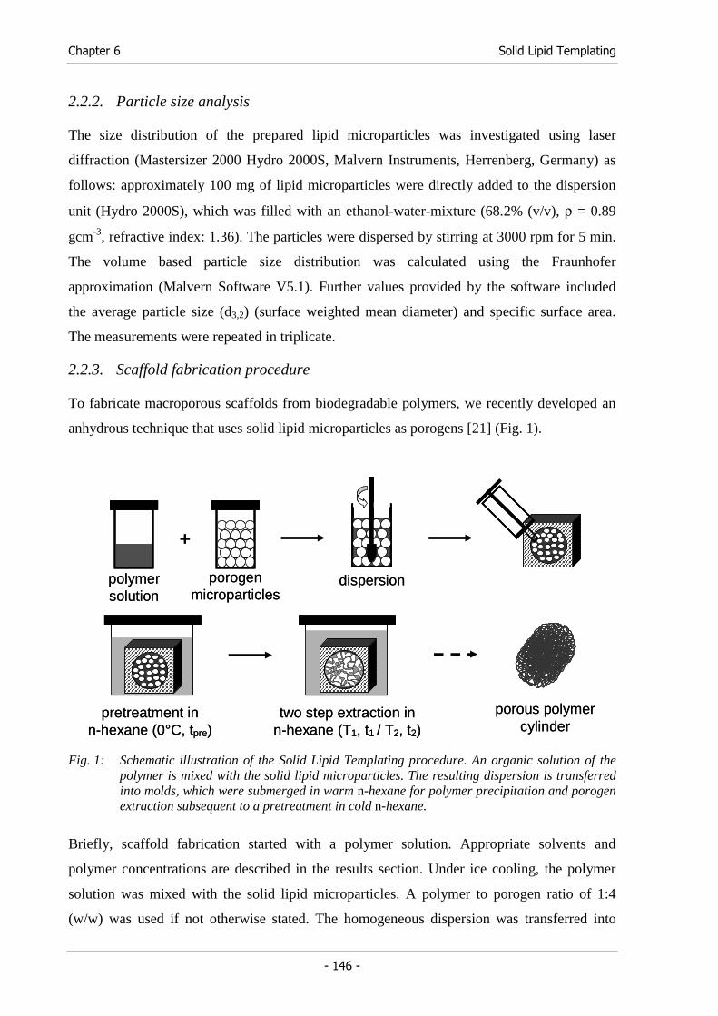
Chapter 6 Solid Lipid Templating
- 146 -
2.2.2. Particle size analysis
The size distribution of the prepared lipid microparticles was investigated using laser
diffraction (Mastersizer 2000 Hydro 2000S, Malvern Instruments, Herrenberg, Germany) as
follows: approximately 100 mg of lipid microparticles were directly added to the dispersion
unit (Hydro 2000S), which was filled with an ethanol-water-mixture (68.2% (v/v), ρ = 0.89
gcm-3, refractive index: 1.36). The particles were dispersed by stirring at 3000 rpm for 5 min.
The volume based particle size distribution was calculated using the Fraunhofer
approximation (Malvern Software V5.1). Further values provided by the software included
the average particle size (d3,2) (surface weighted mean diameter) and specific surface area.
The measurements were repeated in triplicate.
2.2.3. Scaffold fabrication procedure
To fabricate macroporous scaffolds from biodegradable polymers, we recently developed an
anhydrous technique that uses solid lipid microparticles as porogens [21] (Fig. 1).
dispersiondispersionpolymersolutionpolymersolution
porogenmicroparticles
porogenmicroparticles
+
pretreatment inn-hexane (0°C, tpre)
pretreatment inn-hexane (0°C, tpre)
porous polymercylinder
porous polymercylinder
two step extraction inn-hexane (T1, t1 / T2, t2)two step extraction in
n-hexane (T1, t1 / T2, t2)
Fig. 1: Schematic illustration of the Solid Lipid Templating procedure. An organic solution of the polymer is mixed with the solid lipid microparticles. The resulting dispersion is transferred into molds, which were submerged in warm n-hexane for polymer precipitation and porogen extraction subsequent to a pretreatment in cold n-hexane.
Briefly, scaffold fabrication started with a polymer solution. Appropriate solvents and
polymer concentrations are described in the results section. Under ice cooling, the polymer
solution was mixed with the solid lipid microparticles. A polymer to porogen ratio of 1:4
(w/w) was used if not otherwise stated. The homogeneous dispersion was transferred into
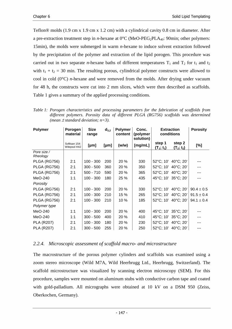
Chapter 6 Solid Lipid Templating
- 147 -
Teflon® molds (1.9 cm x 1.9 cm x 1.2 cm) with a cylindrical cavity 0.8 cm in diameter. After
a pre-extraction treatment step in n-hexane at 0°C (MeO-PEG2PLA40: 90min; other polymers:
15min), the molds were submerged in warm n-hexane to induce solvent extraction followed
by the precipitation of the polymer and extraction of the lipid porogen. This procedure was
carried out in two separate n-hexane baths of different temperatures T1 and T2 for t1 and t2
with t1 + t2 = 30 min. The resulting porous, cylindrical polymer constructs were allowed to
cool in cold (0°C) n-hexane and were removed from the molds. After drying under vacuum
for 48 h, the constructs were cut into 2 mm slices, which were then described as scaffolds.
Table 1 gives a summary of the applied processing conditions.
Table 1: Porogen characteristics and processing parameters for the fabrication of scaffolds from different polymers. Porosity data of different PLGA (RG756) scaffolds was determined (mean ± standard deviation; n=3).
Polymer Porogen material
Size range
d3,2
Polymercontent
Conc. (polymer solution)
Extraction conditions
Porosity
Softisan 154: Witepsol H42 [µm] [µm] (w/w) [mg/mL] step 1
(T1; t1) step 2 (T2; t2)
[%]
Pore size / Rheology PLGA (RG756) 2:1 100 - 300 200 20 % 330 52°C; 10’ 40°C; 20’ --- PLGA (RG756) 2:1 300 - 500 360 20 % 350 52°C; 10’ 40°C; 20’ --- PLGA (RG756) 2:1 500 - 710 590 20 % 365 52°C; 10’ 40°C; 20’ --- MeO-240 1:1 100 - 300 180 25 % 435 45°C; 10’ 35°C; 20’ --- Porosity PLGA (RG756) 2:1 100 - 300 200 20 % 330 52°C; 10’ 40°C; 20’ 90.4 ± 0.5 PLGA (RG756) 2:1 100 - 300 210 15 % 265 52°C; 10’ 40°C; 20’ 91.5 ± 0.4 PLGA (RG756) 2:1 100 - 300 210 10 % 185 52°C; 10’ 40°C; 20’ 94.1 ± 0.4 Polymer type MeO-240 1:1 100 - 300 200 20 % 400 45°C; 10’ 35°C; 20’ --- MeO-240 1:1 300 - 500 400 20 % 410 45°C; 10’ 35°C; 20’ --- PLA (R207) 2:1 100 - 300 180 20 % 230 52°C; 10’ 40°C; 20’ --- PLA (R207) 2:1 300 - 500 255 20 % 250 52°C; 10’ 40°C; 20’ ---
2.2.4. Microscopic assessment of scaffold macro- and microstructure
The macrostructure of the porous polymer cylinders and scaffolds was examined using a
zoom stereo microscope (Wild M7A, Wild Heerbrugg Ltd., Heerbrugg, Switzerland). The
scaffold microstructure was visualized by scanning electron microscopy (SEM). For this
procedure, samples were mounted on aluminum stubs with conductive carbon tape and coated
with gold-palladium. All micrographs were obtained at 10 kV on a DSM 950 (Zeiss,
Oberkochen, Germany).
Chapter 6 Solid Lipid Templating
- 148 -
2.2.5. Oscillatory rheological measurements
The dispersions of porogen particles in polymer solution prepared during scaffold fabrication
were characterized using a Physica MCR 300 rheometer (Anton Paar GmbH, Graz, Austria)
with a 2.5 cm sandblasted steel plate according to the following protocol: Under ice cooling,
the polymer solution was mixed with the solid lipid microparticles for 3 min. The mixture was
transferred to the rheometer using a polypropylenes syringe and equilibrated at 5°C. The
measurement gap was set to 2 mm. After 60 sec, the first frequency sweep (100 – 0.1 Hz) was
measured at a displacement of 0.01% and a temperature of 5°C. A second frequency sweep
(100 – 0.1 Hz at 0.01% displacement) at 5°C followed another equilibration period of 3 min.
The parameters recorded during the second frequency sweep were analyzed to determine the
complex viscosity (η’) of the dispersion. To compare different formulations, the values of the
complex viscosity at 1Hz were interpolated.
2.2.6. Determination of residual porogen material
The detection of triglyceride residues inside the scaffolds was realized through modulated
differential scanning calorimetry (MDSC). The samples were precisely weighed in non-
hermetic AutoDSC aluminum sample pans (TA Instruments, Alzenau, Germany). The sample
pans were sealed using the sample encapsulating press (TA Instruments, Alzenau, Germany)
and analyzed on a DSC 2920 equipped with a refrigerated cooling system and an autosampler
(TA Instruments, Alzenau, Germany). An empty, sealed pan served as reference.
All measurements were carried out between –20 °C and 120 °C. Typically, samples were
equilibrated at –20 °C for 15 min and heated to 120 °C at a heating rate of 5 °C/min. After an
isothermal phase of 15 min, samples were cooled to –20 °C at 5 °C/min. Finally, after another
15 min isothermal phase, samples were again heated to 120 °C at 5 °C/min. A sinusoidal
temperature modulation with a period of 60 s and temperature amplitude of 0.8 °C was
applied to both heating cycles.
The resulting thermograms (total heat flow of the second heating cycle) were analyzed for
melting enthalpy (peak area) of the peak attributed to the melting lipid residuals located near
the glass transition step of the polymer with the Universal Analysis for NT® software
provided with the DSC system.
2.2.7. Determination of scaffold porosity
The porosity of the scaffolds was determined by measuring the dimensions and the mass of
the porous polymer cylinders as obtained from fabrication (cylinder ends were cut away) [24].
Chapter 6 Solid Lipid Templating
- 149 -
The skeletal density of the cylinder (ρ) was calculated from the mass (m), the diameter (d)
and the height (h) of the cylinder:
hd
m
⋅⋅⋅=
2
4
πρ (1)
The porosity (ε) was calculated from the density of the construct (ρ) and density (ρp) of the
polymer (ρp(RG756) = 1.26 gcm-3):
pρ
ρε −= 1 (2)
2.2.8. Chondrocyte cell culture
Primary chondrocytes were isolated from full-thickness bovine articular cartilage by digestion
with type II collagenase (CellSystem, St. Katharinen, Germany) as previously described [25]
and resuspended in culture medium (DMEM) containing 4.5 g/l glucose (Life Technologies
GmbH, Karlsruhe, Germany), 584 mg/l glutamine, 10% FBS (Life Technologies GmbH,
Karlsruhe, Germany), 50 U/mL penicillin, 50 µg/mL streptomycin (Sigma-Aldrich Steinheim,
Germany), 10 mM HEPES (Sigma-Aldrich Steinheim, Germany), 0.1 mM non-essential
amino acids (Life Technologies GmbH, Karlsruhe, Germany), 0.4 mM proline (Sigma-
Aldrich Steinheim, Germany), and 50 µg/mL ascorbic acid (Sigma-Aldrich Steinheim,
Germany). This medium was also used for cell seeding and cultivation.
The cells were seeded in spinner flasks, as described elsewhere [22]. In brief, a cell
suspension containing 5 x 10⁶ chondrocytes per scaffold was stirred at 80 rpm in a humidified
(37 °C / 5% CO2) incubator for two days to allow for cell attachment to the polymers.
Cell-polymer constructs were transferred into 6-well plates (one construct and 6 mL culture
medium per well) and cultured for three weeks on an orbital shaker at 50 rpm. Medium
supplemented with different amounts of insulin (0 µg/mL, 0.05 µg/mL, 2.5 µg/mL) was
completely exchanged three times per week.
At the end of the culture period, each cell-polymer construct was weighed (= wet weight) and
cut in half. One part was prepared as histological sample by fixing in 2% glutaraldehyde in
PBS for 30 min and then in 10% formalin. The samples were embedded in paraffin and cross-
sectioned (5 µm thick). Deparaffinized sections were stained with hematoxylin and eosin
(H&E) (C.I.: 45380, Sigma-Aldrich, Steinheim, Germany) for cells and safranin-O for
glycosaminoglycans (GAG). The other half of the construct was used for biochemical analysis
of the collagen content and GAG content [22].
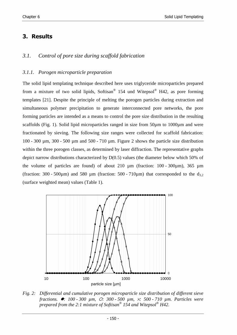
Chapter 6 Solid Lipid Templating
- 150 -
3. Results
3.1. Control of pore size during scaffold fabrication
3.1.1. Porogen microparticle preparation
The solid lipid templating technique described here uses triglyceride microparticles prepared
from a mixture of two solid lipids, Softisan® 154 und Witepsol® H42, as pore forming
templates [21]. Despite the principle of melting the porogen particles during extraction and
simultaneous polymer precipitation to generate interconnected pore networks, the pore
forming particles are intended as a means to control the pore size distribution in the resulting
scaffolds (Fig. 1). Solid lipid microparticles ranged in size from 50µm to 1000µm and were
fractionated by sieving. The following size ranges were collected for scaffold fabrication:
100 - 300 µm, 300 - 500 µm and 500 - 710 µm. Figure 2 shows the particle size distribution
within the three porogen classes, as determined by laser diffraction. The representative graphs
depict narrow distributions characterized by D(0.5) values (the diameter below which 50% of
the volume of particles are found) of about 210 µm (fraction: 100 - 300µm), 365 µm
(fraction: 300 - 500µm) and 580 µm (fraction: 500 - 710µm) that corresponded to the d3,2
(surface weighted mean) values (Table 1).
10 100 1000 10000particle size [µm]
0
50
100
Fig. 2: Differential and cumulative porogen microparticle size distribution of different sieve fractions. : 100 - 300 µm, : 300 - 500 µm, ×: 500 - 710 µm. Particles were prepared from the 2:1 mixture of Softisan® 154 and Witepsol® H42.
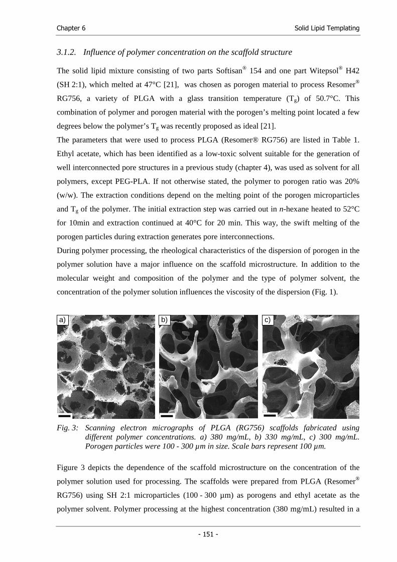
Chapter 6 Solid Lipid Templating
- 151 -
3.1.2. Influence of polymer concentration on the scaffold structure
The solid lipid mixture consisting of two parts Softisan® 154 and one part Witepsol® H42
(SH 2:1), which melted at 47°C [21], was chosen as porogen material to process Resomer®
RG756, a variety of PLGA with a glass transition temperature (Tg) of 50.7°C. This
combination of polymer and porogen material with the porogen’s melting point located a few
degrees below the polymer’s Tg was recently proposed as ideal [21].
The parameters that were used to process PLGA (Resomer® RG756) are listed in Table 1.
Ethyl acetate, which has been identified as a low-toxic solvent suitable for the generation of
well interconnected pore structures in a previous study (chapter 4), was used as solvent for all
polymers, except PEG-PLA. If not otherwise stated, the polymer to porogen ratio was 20%
(w/w). The extraction conditions depend on the melting point of the porogen microparticles
and Tg of the polymer. The initial extraction step was carried out in n-hexane heated to 52°C
for 10min and extraction continued at 40°C for 20 min. This way, the swift melting of the
porogen particles during extraction generates pore interconnections.
During polymer processing, the rheological characteristics of the dispersion of porogen in the
polymer solution have a major influence on the scaffold microstructure. In addition to the
molecular weight and composition of the polymer and the type of polymer solvent, the
concentration of the polymer solution influences the viscosity of the dispersion (Fig. 1).
Fig. 3: Scanning electron micrographs of PLGA (RG756) scaffolds fabricated using different polymer concentrations. a) 380 mg/mL, b) 330 mg/mL, c) 300 mg/mL. Porogen particles were 100 - 300 µm in size. Scale bars represent 100 µm.
Figure 3 depicts the dependence of the scaffold microstructure on the concentration of the
polymer solution used for processing. The scaffolds were prepared from PLGA (Resomer®
RG756) using SH 2:1 microparticles (100 - 300 µm) as porogens and ethyl acetate as the
polymer solvent. Polymer processing at the highest concentration (380 mg/mL) resulted in a
a) b) c)
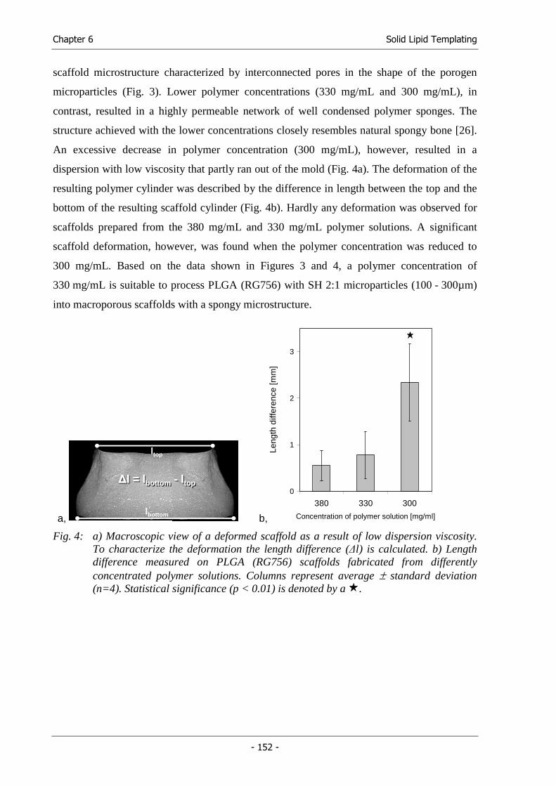
Chapter 6 Solid Lipid Templating
- 152 -
scaffold microstructure characterized by interconnected pores in the shape of the porogen
microparticles (Fig. 3). Lower polymer concentrations (330 mg/mL and 300 mg/mL), in
contrast, resulted in a highly permeable network of well condensed polymer sponges. The
structure achieved with the lower concentrations closely resembles natural spongy bone [26].
An excessive decrease in polymer concentration (300 mg/mL), however, resulted in a
dispersion with low viscosity that partly ran out of the mold (Fig. 4a). The deformation of the
resulting polymer cylinder was described by the difference in length between the top and the
bottom of the resulting scaffold cylinder (Fig. 4b). Hardly any deformation was observed for
scaffolds prepared from the 380 mg/mL and 330 mg/mL polymer solutions. A significant
scaffold deformation, however, was found when the polymer concentration was reduced to
300 mg/mL. Based on the data shown in Figures 3 and 4, a polymer concentration of
330 mg/mL is suitable to process PLGA (RG756) with SH 2:1 microparticles (100 - 300µm)
into macroporous scaffolds with a spongy microstructure.
a,
ltop
lbottom
∆l = lbottom - ltop∆∆l = l = llbottombottom -- lltoptop
b,
0
1
2
3
380 330 300
Concentration of polymer solution [mg/ml]
Leng
th d
iffer
ence
[mm
]
Fig. 4: a) Macroscopic view of a deformed scaffold as a result of low dispersion viscosity. To characterize the deformation the length difference (∆l) is calculated. b) Length difference measured on PLGA (RG756) scaffolds fabricated from differently concentrated polymer solutions. Columns represent average ± standard deviation (n=4). Statistical significance (p < 0.01) is denoted by a .
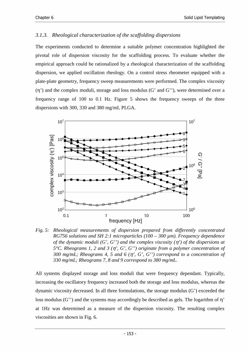
Chapter 6 Solid Lipid Templating
- 153 -
3.1.3. Rheological characterization of the scaffolding dispersions
The experiments conducted to determine a suitable polymer concentration highlighted the
pivotal role of dispersion viscosity for the scaffolding process. To evaluate whether the
empirical approach could be rationalized by a rheological characterization of the scaffolding
dispersion, we applied oscillation rheology. On a control stress rheometer equipped with a
plate-plate geometry, frequency sweep measurements were performed. The complex viscosity
(η’) and the complex moduli, storage and loss modulus (G’ and G’’), were determined over a
frequency range of 100 to 0.1 Hz. Figure 5 shows the frequency sweeps of the three
dispersions with 300, 330 and 380 mg/mL PLGA.
1,00E+02
1,00E+03
1,00E+04
1,00E+05
1,00E+06
1,00E+07
0,1 1 10 100
1,00E+05
1,00E+06
1,00E+07107
105
106
104
103
102
0.1
107
106
105
1 10 100frequency [Hz]
com
plex
vis
cosi
ty (
η’)
[Pas
]G
’ / G’’ [P
a]
1
2
34
56
7
8
9
Fig. 5: Rheological measurements of dispersion prepared from differently concentrated RG756 solutions and SH 2:1 microparticles (100 – 300 µm). Frequency dependence of the dynamic moduli (G’, G’’) and the complex viscosity (η’) of the dispersions at 5°C. Rheograms 1, 2 and 3 (η’, G’, G’’) originate from a polymer concentration of 300 mg/mL; Rheograms 4, 5 and 6 (η’, G’, G’’) correspond to a concentration of 330 mg/mL; Rheograms 7, 8 and 9 correspond to 380 mg/mL.
All systems displayed storage and loss moduli that were frequency dependant. Typically,
increasing the oscillatory frequency increased both the storage and loss modulus, whereas the
dynamic viscosity decreased. In all three formulations, the storage modulus (G’) exceeded the
loss modulus (G’’) and the systems may accordingly be described as gels. The logarithm of η’
at 1Hz was determined as a measure of the dispersion viscosity. The resulting complex
viscosities are shown in Fig. 6.
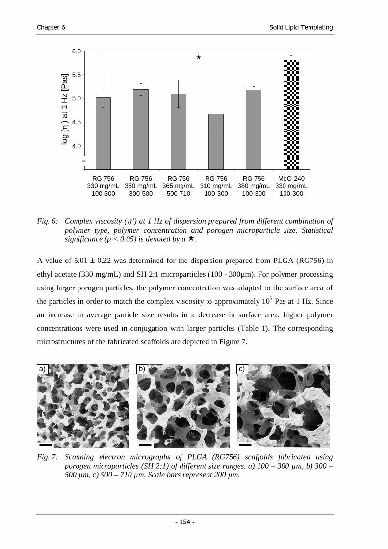
Chapter 6 Solid Lipid Templating
- 154 -
Fig. 6: Complex viscosity (η’) at 1 Hz of dispersion prepared from different combination of polymer type, polymer concentration and porogen microparticle size. Statistical significance (p < 0.05) is denoted by a .
A value of 5.01 ± 0.22 was determined for the dispersion prepared from PLGA (RG756) in
ethyl acetate (330 mg/mL) and SH 2:1 microparticles (100 - 300µm). For polymer processing
using larger porogen particles, the polymer concentration was adapted to the surface area of
the particles in order to match the complex viscosity to approximately 105 Pas at 1 Hz. Since
an increase in average particle size results in a decrease in surface area, higher polymer
concentrations were used in conjugation with larger particles (Table 1). The corresponding
microstructures of the fabricated scaffolds are depicted in Figure 7.
Fig. 7: Scanning electron micrographs of PLGA (RG756) scaffolds fabricated using porogen microparticles (SH 2:1) of different size ranges. a) 100 – 300 µm, b) 300 – 500 µm, c) 500 – 710 µm. Scale bars represent 200 µm.
a) b) c)
3,5
4
4,5
5
5,5
6
RG 756330 mg/mL
100-300
RG 756350 mg/mL
300-500
RG 756365 mg/mL
500-710
RG 756310 mg/mL
100-300
RG 756380 mg/mL
100-300
MeO-240330 mg/mL
100-300
log1
0 (c
ompl
ex v
isco
sity
) at
1H
z [P
as]
6.0
5.5
5.0
4.5
4.0
=
log
(η‘)
at 1
Hz
[Pas
]
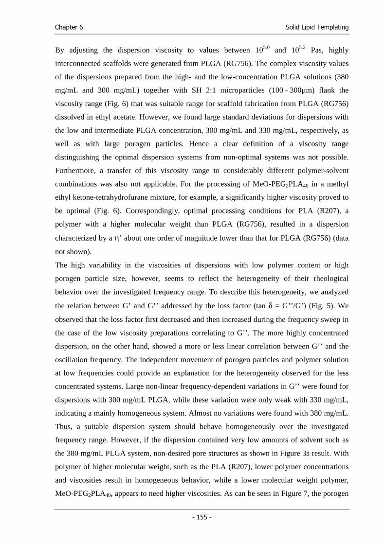
Chapter 6 Solid Lipid Templating
- 155 -
By adjusting the dispersion viscosity to values between 105.0 and 105.2 Pas, highly
interconnected scaffolds were generated from PLGA (RG756). The complex viscosity values
of the dispersions prepared from the high- and the low-concentration PLGA solutions (380
mg/mL and 300 mg/mL) together with SH 2:1 microparticles (100 - 300µm) flank the
viscosity range (Fig. 6) that was suitable range for scaffold fabrication from PLGA (RG756)
dissolved in ethyl acetate. However, we found large standard deviations for dispersions with
the low and intermediate PLGA concentration, 300 mg/mL and 330 mg/mL, respectively, as
well as with large porogen particles. Hence a clear definition of a viscosity range
distinguishing the optimal dispersion systems from non-optimal systems was not possible.
Furthermore, a transfer of this viscosity range to considerably different polymer-solvent
combinations was also not applicable. For the processing of MeO-PEG2PLA40 in a methyl
ethyl ketone-tetrahydrofurane mixture, for example, a significantly higher viscosity proved to
be optimal (Fig. 6). Correspondingly, optimal processing conditions for PLA (R207), a
polymer with a higher molecular weight than PLGA (RG756), resulted in a dispersion
characterized by a η’ about one order of magnitude lower than that for PLGA (RG756) (data
not shown).
The high variability in the viscosities of dispersions with low polymer content or high
porogen particle size, however, seems to reflect the heterogeneity of their rheological
behavior over the investigated frequency range. To describe this heterogeneity, we analyzed
the relation between G’ and G’’ addressed by the loss factor (tan δ = G’’/G’) (Fig. 5). We
observed that the loss factor first decreased and then increased during the frequency sweep in
the case of the low viscosity preparations correlating to G’’. The more highly concentrated
dispersion, on the other hand, showed a more or less linear correlation between G’’ and the
oscillation frequency. The independent movement of porogen particles and polymer solution
at low frequencies could provide an explanation for the heterogeneity observed for the less
concentrated systems. Large non-linear frequency-dependent variations in G’’ were found for
dispersions with 300 mg/mL PLGA, while these variation were only weak with 330 mg/mL,
indicating a mainly homogeneous system. Almost no variations were found with 380 mg/mL.
Thus, a suitable dispersion system should behave homogeneously over the investigated
frequency range. However, if the dispersion contained very low amounts of solvent such as
the 380 mg/mL PLGA system, non-desired pore structures as shown in Figure 3a result. With
polymer of higher molecular weight, such as the PLA (R207), lower polymer concentrations
and viscosities result in homogeneous behavior, while a lower molecular weight polymer,
MeO-PEG2PLA40, appears to need higher viscosities. As can be seen in Figure 7, the porogen
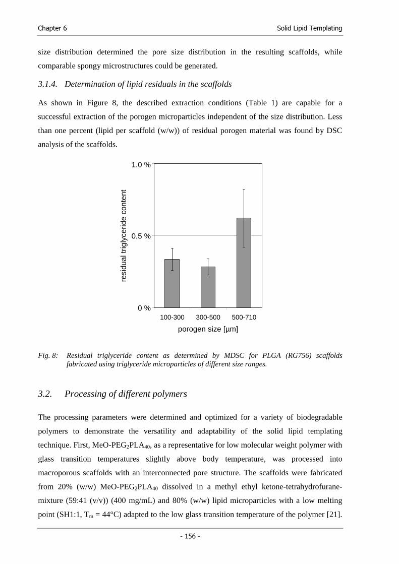
Chapter 6 Solid Lipid Templating
- 156 -
size distribution determined the pore size distribution in the resulting scaffolds, while
comparable spongy microstructures could be generated.
3.1.4. Determination of lipid residuals in the scaffolds
As shown in Figure 8, the described extraction conditions (Table 1) are capable for a
successful extraction of the porogen microparticles independent of the size distribution. Less
than one percent (lipid per scaffold (w/w)) of residual porogen material was found by DSC
analysis of the scaffolds.
0,0%
0,5%
1,0%
100-300 300-500 500-710
porogen size [µm]
resi
dual
trig
lyce
ride
cont
ent
1.0 %
0.5 %
0 %
Fig. 8: Residual triglyceride content as determined by MDSC for PLGA (RG756) scaffolds fabricated using triglyceride microparticles of different size ranges.
3.2. Processing of different polymers
The processing parameters were determined and optimized for a variety of biodegradable
polymers to demonstrate the versatility and adaptability of the solid lipid templating
technique. First, MeO-PEG2PLA40, as a representative for low molecular weight polymer with
glass transition temperatures slightly above body temperature, was processed into
macroporous scaffolds with an interconnected pore structure. The scaffolds were fabricated
from 20% (w/w) MeO-PEG2PLA40 dissolved in a methyl ethyl ketone-tetrahydrofurane-
mixture (59:41 (v/v)) (400 mg/mL) and 80% (w/w) lipid microparticles with a low melting
point (SH1:1, Tm = 44°C) adapted to the low glass transition temperature of the polymer [21].
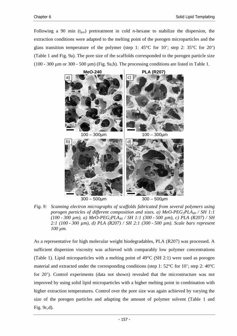
Chapter 6 Solid Lipid Templating
- 157 -
Following a 90 min (tpre) pretreatment in cold n-hexane to stabilize the dispersion, the
extraction conditions were adapted to the melting point of the porogen microparticles and the
glass transition temperature of the polymer (step 1: 45°C for 10’; step 2: 35°C for 20’)
(Table 1 and Fig. 9a). The pore size of the scaffolds corresponded to the porogen particle size
(100 - 300 µm or 300 - 500 µm) (Fig. 9a,b). The processing conditions are listed in Table 1.
MeO-240 PLA (R207)
100 – 300µm 100 – 300µm
300 – 500µm 300 – 500µm
Fig. 9: Scanning electron micrographs of scaffolds fabricated from several polymers using porogen particles of different composition and sizes. a) MeO-PEG2PLA40 / SH 1:1 (100 - 300 µm), a) MeO-PEG2PLA40 / SH 1:1 (300 - 500 µm), c) PLA (R207) / SH 2:1 (100 - 300 µm), d) PLA (R207) / SH 2:1 (300 - 500 µm). Scale bars represent 100 µm.
As a representative for high molecular weight biodegradables, PLA (R207) was processed. A
sufficient dispersion viscosity was achieved with comparably low polymer concentrations
(Table 1). Lipid microparticles with a melting point of 49°C (SH 2:1) were used as porogen
material and extracted under the corresponding conditions (step 1: 52°C for 10’; step 2: 40°C
for 20’). Control experiments (data not shown) revealed that the microstructure was not
improved by using solid lipid microparticles with a higher melting point in combination with
higher extraction temperatures. Control over the pore size was again achieved by varying the
size of the porogen particles and adapting the amount of polymer solvent (Table 1 and
Fig. 9c,d).
a) c)
b) d)
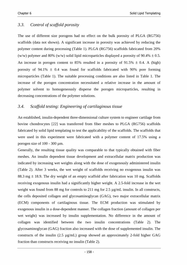
Chapter 6 Solid Lipid Templating
- 158 -
3.3. Control of scaffold porosity
The use of different size porogens had no effect on the bulk porosity of PLGA (RG756)
scaffolds (data not shown). A significant increase in porosity was achieved by reducing the
polymer content during processing (Table 1). PLGA (RG756) scaffolds fabricated from 20%
(w/w) polymer and 80% (w/w) solid lipid microparticles displayed a porosity of 90.4% ± 0.5.
An increase in porogen content to 85% resulted in a porosity of 91.5% ± 0.4. A (high)
porosity of 94.1% ± 0.4 was found for scaffolds fabricated with 90% pore forming
microparticles (Table 1). The suitable processing conditions are also listed in Table 1. The
increase of the porogen concentration necessitated a relative increase in the amount of
polymer solvent to homogeneously disperse the porogen microparticles, resulting in
decreasing concentrations of the polymer solutions.
3.4. Scaffold testing: Engineering of cartilaginous tissue
An established, insulin-dependent three-dimensional culture system to engineer cartilage from
bovine chondrocytes [22] was transferred from fiber meshes to PLGA (RG756) scaffolds
fabricated by solid lipid templating to test the applicability of the scaffolds. The scaffolds that
were used in this experiment were fabricated with a polymer content of 17.5% using a
porogen size of 100 - 300 µm.
Generally, the resulting tissue quality was comparable to that typically obtained with fiber
meshes. An insulin dependent tissue development and extracellular matrix production was
indicated by increasing wet weights along with the dose of exogenously administered insulin
(Table 2). After 3 weeks, the wet weight of scaffolds receiving no exogenous insulin was
88.3 mg ± 18.9. The dry weight of an empty scaffold after fabrication was 10 mg. Scaffolds
receiving exogenous insulin had a significantly higher weight. A 2.5-fold increase in the wet
weight was found from 88 mg for controls to 211 mg for 2.5 µg/mL insulin. In all constructs,
the cells deposited collagen and glycosaminoglycan (GAG), two major extracellular matrix
(ECM) components of cartilaginous tissue. The ECM production was stimulated by
exogenous insulin in a dose-dependent manner. The collagen fraction (amount of collagen per
wet weight) was increased by insulin supplementation. No difference in the amount of
collagen was identified between the two insulin concentrations (Table 2). The
glycosaminoglycan (GAG) fraction also increased with the dose of supplemented insulin. The
constructs of the insulin (2.5 µg/mL) group showed an approximately 2-fold higher GAG
fraction than constructs receiving no insulin (Table 2).
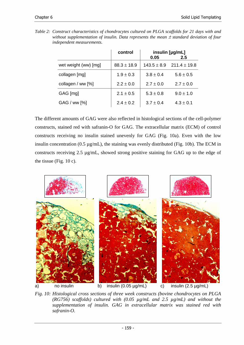
Chapter 6 Solid Lipid Templating
- 159 -
Table 2: Construct characteristics of chondrocytes cultured on PLGA scaffolds for 21 days with and without supplementation of insulin. Data represents the mean ± standard deviation of four independent measurements.
control insulin [µg/mL] 0.05 2.5
wet weight (ww) [mg] 88.3 ± 18.9 143.5 ± 8.9 211.4 ± 19.8
collagen [mg] 1.9 ± 0.3 3.8 ± 0.4 5.6 ± 0.5
collagen / ww [%] 2.2 ± 0.0 2.7 ± 0.0 2.7 ± 0.0
GAG [mg] 2.1 ± 0.5 5.3 ± 0.8 9.0 ± 1.0
GAG / ww [%] 2.4 ± 0.2 3.7 ± 0.4 4.3 ± 0.1
The different amounts of GAG were also reflected in histological sections of the cell-polymer
constructs, stained red with safranin-O for GAG. The extracellular matrix (ECM) of control
constructs receiving no insulin stained unevenly for GAG (Fig. 10a). Even with the low
insulin concentration (0.5 µg/mL), the staining was evenly distributed (Fig. 10b). The ECM in
constructs receiving 2.5 µg/mL, showed strong positive staining for GAG up to the edge of
the tissue (Fig. 10 c).
a) no insulin b) insulin (0.05 µg/mL) c) insulin (2.5 µg/mL)
Fig. 10: Histological cross sections of three week constructs (bovine chondrocytes on PLGA (RG756) scaffolds) cultured with (0.05 µg/mL and 2.5 µg/mL) and without the supplementation of insulin. GAG in extracellular matrix was stained red with safranin-O.
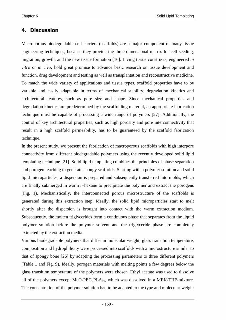
Chapter 6 Solid Lipid Templating
- 160 -
4. Discussion
Macroporous biodegradable cell carriers (scaffolds) are a major component of many tissue
engineering techniques, because they provide the three-dimensional matrix for cell seeding,
migration, growth, and the new tissue formation [16]. Living tissue constructs, engineered in
vitro or in vivo, hold great promise to advance basic research on tissue development and
function, drug development and testing as well as transplantation and reconstructive medicine.
To match the wide variety of applications and tissue types, scaffold properties have to be
variable and easily adaptable in terms of mechanical stability, degradation kinetics and
architectural features, such as pore size and shape. Since mechanical properties and
degradation kinetics are predetermined by the scaffolding material, an appropriate fabrication
technique must be capable of processing a wide range of polymers [27]. Additionally, the
control of key architectural properties, such as high porosity and pore interconnectivity that
result in a high scaffold permeability, has to be guaranteed by the scaffold fabrication
technique.
In the present study, we present the fabrication of macroporous scaffolds with high interpore
connectivity from different biodegradable polymers using the recently developed solid lipid
templating technique [21]. Solid lipid templating combines the principles of phase separation
and porogen leaching to generate spongy scaffolds. Starting with a polymer solution and solid
lipid microparticles, a dispersion is prepared and subsequently transferred into molds, which
are finally submerged in warm n-hexane to precipitate the polymer and extract the porogens
(Fig. 1). Mechanistically, the interconnected porous microstructure of the scaffolds is
generated during this extraction step. Ideally, the solid lipid microparticles start to melt
shortly after the dispersion is brought into contact with the warm extraction medium.
Subsequently, the molten triglycerides form a continuous phase that separates from the liquid
polymer solution before the polymer solvent and the triglyceride phase are completely
extracted by the extraction media.
Various biodegradable polymers that differ in molecular weight, glass transition temperature,
composition and hydrophilicity were processed into scaffolds with a microstructure similar to
that of spongy bone [26] by adapting the processing parameters to three different polymers
(Table 1 and Fig. 9). Ideally, porogen materials with melting points a few degrees below the
glass transition temperature of the polymers were chosen. Ethyl acetate was used to dissolve
all of the polymers except MeO-PEG2PLA40, which was dissolved in a MEK-THF-mixture.
The concentration of the polymer solution had to be adapted to the type and molecular weight
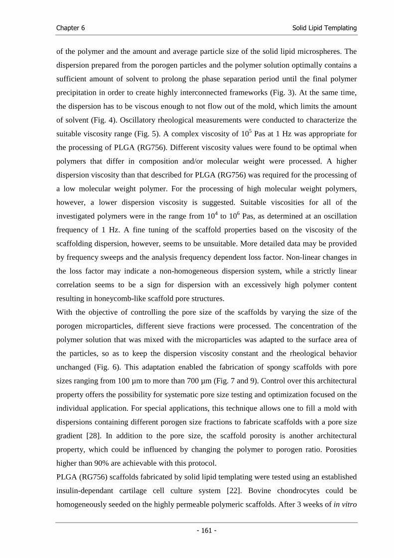
Chapter 6 Solid Lipid Templating
- 161 -
of the polymer and the amount and average particle size of the solid lipid microspheres. The
dispersion prepared from the porogen particles and the polymer solution optimally contains a
sufficient amount of solvent to prolong the phase separation period until the final polymer
precipitation in order to create highly interconnected frameworks (Fig. 3). At the same time,
the dispersion has to be viscous enough to not flow out of the mold, which limits the amount
of solvent (Fig. 4). Oscillatory rheological measurements were conducted to characterize the
suitable viscosity range (Fig. 5). A complex viscosity of 105 Pas at 1 Hz was appropriate for
the processing of PLGA (RG756). Different viscosity values were found to be optimal when
polymers that differ in composition and/or molecular weight were processed. A higher
dispersion viscosity than that described for PLGA (RG756) was required for the processing of
a low molecular weight polymer. For the processing of high molecular weight polymers,
however, a lower dispersion viscosity is suggested. Suitable viscosities for all of the
investigated polymers were in the range from 104 to 106 Pas, as determined at an oscillation
frequency of 1 Hz. A fine tuning of the scaffold properties based on the viscosity of the
scaffolding dispersion, however, seems to be unsuitable. More detailed data may be provided
by frequency sweeps and the analysis frequency dependent loss factor. Non-linear changes in
the loss factor may indicate a non-homogeneous dispersion system, while a strictly linear
correlation seems to be a sign for dispersion with an excessively high polymer content
resulting in honeycomb-like scaffold pore structures.
With the objective of controlling the pore size of the scaffolds by varying the size of the
porogen microparticles, different sieve fractions were processed. The concentration of the
polymer solution that was mixed with the microparticles was adapted to the surface area of
the particles, so as to keep the dispersion viscosity constant and the rheological behavior
unchanged (Fig. 6). This adaptation enabled the fabrication of spongy scaffolds with pore
sizes ranging from 100 µm to more than 700 µm (Fig. 7 and 9). Control over this architectural
property offers the possibility for systematic pore size testing and optimization focused on the
individual application. For special applications, this technique allows one to fill a mold with
dispersions containing different porogen size fractions to fabricate scaffolds with a pore size
gradient [28]. In addition to the pore size, the scaffold porosity is another architectural
property, which could be influenced by changing the polymer to porogen ratio. Porosities
higher than 90% are achievable with this protocol.
PLGA (RG756) scaffolds fabricated by solid lipid templating were tested using an established
insulin-dependant cartilage cell culture system [22]. Bovine chondrocytes could be
homogeneously seeded on the highly permeable polymeric scaffolds. After 3 weeks of in vitro
Chapter 6 Solid Lipid Templating
- 162 -
culture, considerable amounts of extracellular matrix were synthesized by the chondrocytes.
Histological staining with safranin-O confirmed the presence of glycosaminoglycans (GAG),
a cartilage-specific extracellular matrix component, in the scaffolds, albeit unevenly
distributed. The supplementation of exogenous insulin dose-dependently increased the wet
weight of the constructs as well as collagen and GAG production. Histological cross-sections
of the constructs showed a strong and homogenous staining for GAG throughout the entire
scaffold. Thus, the scaffolds proved to be sufficiently permeable to cells, nutrients and wastes
and allowed for cartilage tissue development throughout the whole scaffold. In fact, the
results were comparable to those obtained on fiber meshes, which represent the “gold-
standard” for porosity and permeability. No sign of dedifferentiation was observed, but rather
the chondrocytes reacted strongly to the exogenous insulin stimuli, resulting in an improved
tissue development. In summary, the generated microstructure proved to be suitable for
cartilage tissue engineering and will be used for the cultivation of other tissue types in future
experiments.
As shown in this study, solid lipid templating is a technique that can be adapted to a variety of
different polymers, offers easy control of architectural properties, such as pore size and
porosity, and generates spongy frameworks characterized by high pore interconnectivity. In
addition, this technique avoids aqueous media so that experimental polymers bearing
hydrolysable functional groups or water-soluble polymers can be incorporated into the
scaffolding. Further advantages of this technique include: First, bioactive proteins, such as
growth factors, can be directly encapsulated as solids during scaffold fabrication and will be
released when the scaffold is brought into contact with body fluids or cell culture medium.
Second, there is no requirement for sophisticated equipment, unlike the textile technology,
solid free-form fabrication or three-dimensional printing. Third, the porogen extraction is
completed after 30 min, while conventional porogen leaching techniques require extraction
times from hours up to days. Fourth, the scaffold can be directly fabricated into a specific
anatomical shape with a mold. Fifth, the process can be easily expanded or automated for
large-scale production.
Chapter 6 Solid Lipid Templating
- 163 -
5. Conclusion
In conclusion, the solid lipid templating technique is capable of producing tailored cell
carriers for a variety of tissue engineering and biomedical applications. Processing conditions
can be adapted to a variety of polymers offering different physical, mechanical and
degradation properties. Architectural properties, such as pore size and porosity can be easily
controlled and pore interconnectivity can be guaranteed.
Chapter 6 Solid Lipid Templating
- 164 -
6. References
(1) Langer R, Vacanti JP. 'Tissue engineering'. Science (1993); 260: 920-926.
(2) Cima LG, Vacanti JP, Vacanti C, Ingber D, Mooney D, Langer R. 'Tissue engineering by cell transplantation using degradable polymer substrates'. J Biomed Eng (1991); 113: 143-151.
(3) Mooney DJ, Mikos AG. 'Growing new organs'. Sci Am (1999); 280: 60-65.
(4) Tabata Y. 'The importance of drug delivery systems in tissue engineering'. Pharm Sci Technol Today (2000); 3: 80-89.
(5) Liu X, Ma PX. 'Polymeric scaffolds for bone tissue engineering'. Ann Biomed Eng (2004); 32: 477-486.
(6) Freed LE, Vunjak NG, Biron RJ, Eagles DB, Lesnoy DC, Barlow SK, Langer R. 'Biodegradable polymer scaffolds for tissue engineering'. Biotechnology (N Y ) (1994); 12: 689-693.
(7) Agrawal CM, Ray RB. 'Biodegradable polymeric scaffolds for musculoskeletal tissue engineering'. J Biomed Mater Res (2001); 55: 141-150.
(8) Mikos AG, Thorsen AJ, Czerwonka LA, Bao Y, Langer R, Winslow DN, Vacanti JP. 'Preparation and characterization of poly(-lactic acid) foams'. Polymer (1994); 35: 1068-1077.
(9) Mikos AG, Sarakinos G, Leite SM, Vacanti JP, Langer R. 'Laminated three-dimensional biodegradable foams for use in tissue engineering'. Biomaterials (1993); 14: 323-330.
(10) Mooney DJ, Baldwin DF, Suh NP, Vacanti JP, Langer R. 'Novel approach to fabricate porous sponges of poly(,-lactic-co-glycolic acid) without the use of organic solvents'. Biomaterials (1996); 17: 1417-1422.
(11) Nam YS, Park TG. 'Biodegradable polymeric microcellular foams by modified thermally induced phase separation method'. Biomaterials (1999); 20: 1783-1790.
(12) Leong KF, Cheah CM, Chua CK. 'Solid freeform fabrication of three-dimensional scaffolds for engineering replacement tissues and organs'. Biomaterials (2003); 24: 2363-2378.
(13) Ma PX, Choi JW. 'Biodegradable polymer scaffolds with well-defined interconnected spherical pore network'. Tissue Eng (2001); 7: 23-33.
(14) Sachlos E, Czernuszka JT. 'Making tissue engineering scaffolds work. Review on the application of solid freeform fabrication technology to the production of tissue engineering scaffolds'. Eur Cell Mater (2003); 5: 29-40.
(15) Hutmacher DW. 'Scaffolds in tissue engineering bone and cartilage'. Biomaterials (2000); 21: 2529-2543.
Chapter 6 Solid Lipid Templating
- 165 -
(16) Hutmacher DW. 'Scaffold design and fabrication technologies for engineering tissues - State of the art and future perspectives'. J Biomater Sci , Polym Ed (2001); 12: 107-124.
(17) Murphy WL, Dennis RG, Kileny JL, Mooney DJ. 'Salt Fusion: An Approach to Improve Pore Interconnectivity within Tissue Engineering Scaffolds'. Tissue Eng (2002); 8: 43-52.
(18) Holy CE, Fialkov JA, Davies JE, Shoichet MS. 'Use of a biomimetic strategy to engineer bone'. J Biomed Mater Res (2003); 65A: 447-453.
(19) Tessmar JK, Mikos AG, Goepferich A. 'Amine-Reactive Biodegradable Diblock Copolymers'. Biomacromolecules (2002); 3: 194-200.
(20) Shastri VP, Martin I, Langer R. 'Macroporous polymer foams by hydrocarbon templating'. Proc Natl Acad Sci U S A (2000); 97: 1970-1975.
(21) Hacker M, Tessmar J, Neubauer M, Blaimer A, Blunk T, Gopferich A, Schulz MB. 'Towards biomimetic scaffolds: Anhydrous scaffold fabrication from biodegradable amine-reactive diblock copolymers'. Biomaterials (2003); 24: 4459-4473.
(22) Kellner K, Schulz MB, Gopferich A, Blunk T. 'Insulin in tissue engineering of cartilage: A potential model system for growth factor application'. J Drug Targeting (2001); 9: 439-448.
(23) Lucke A, Tessmar J, Schnell E, Schmeer G, Gopferich A. 'Biodegradable poly(,-lactic acid)-poly(ethylene glycol)-monomethyl ether diblock copolymers: structures and surface properties relevant to their use as biomaterials'. Biomaterials (2000); 21: 2361-2370.
(24) Ma PX, Zhang R. 'Synthetic nano-scale fibrous extracellular matrix'. J Biomed Mater Res (1999); 46: 60-72.
(25) Freed LE, Marquis JC, Nohria A, Emmanual J, Mikos AG, Langer R. 'Neocartilage formation in vitro and in vivo using cells cultured on synthetic biodegradable polymers'. J Biomed Mater Res (1993); 27: 11-23.
(26) Nazarian A, Muller R. 'Time-lapsed microstructural imaging of bone failure behavior'. J Biomech (2004); 37: 55-65.
(27) Wu L, Ding J. 'In vitro degradation of three-dimensional porous poly(,-lactide-co-glycolide) scaffolds for tissue engineering'. Biomaterials (2004); 25: 5821-5830.
(28) Sherwood JK, Riley SL, Palazzolo R, Brown SC, Monkhouse DC, Coates M, Griffith LG, Landeen LK, Ratcliffe A. 'A three-dimensional osteochondral composite scaffold for articular cartilage repair'. Biomaterials (2002); 23: 4739-4751.

Functional Cell Carriers for Tissue Engineering
Chapter 7
Synthesis and Characterization of Injectable, Thermogelling Poly(N-isopropylacrylamide)-
grafted Gelatin (PNiPAAm-gelatin)
Michael Hacker1, Thomas Vogel2, Markus Neubauer1, Bernhard Appel1, Miriam Breunig1,
Torsten Blunk1, Achim Göpferich1, Michaela B. Schulz1,2
1 Department of Pharmaceutical Technology, University of Regensburg,
Universitaetsstrasse 31, 93040 Regensburg, Germany 2 Department of Pharmaceutical Technology, University of Graz,
Schubertstrasse 6, 8010 Graz, Austria
European Journal of Pharmaceutics and Biopharmaceutics (to be submitted)

Chapter 7 Thermogelling PNiPAAm-gelatin
- 169 -
1. Introduction
In living tissues, cells are embedded in a three-dimensional hydrated, insoluble network of
proteins and glycosaminoglycans, the extracellular matrix (ECM). The ECM proteins interact
with cells via integrins, which are heterodimeric receptors in the cell membrane, and regulate
their development, migration, proliferation and metabolic function. In recent years, a variety
of hydrogel materials have been explored for use as ECM substitutes. Both natural and
synthetic hydrogel forming materials have been studied as a means of cell transplantation to
reconstruct tissue defects. Natural materials, such as fibrin and especially collagen, are of
interest since they are ECM proteins and susceptible to cell-triggered proteolysis by matrix
metalloproteases, which enables cell invasion and migration and subsequent remodeling of
the gel matrix. Furthermore, the highly ordered nanostructure of collagen plays an important
role in various biological events in the body during development and regeneration processes.
Consequently, these materials have been employed as cell carriers in numerous studies that
were focused on the regeneration of various tissues, ranging from vascular grafts to bone
[1-5]. However, natural materials have some inherent limitations in clinical use, primarily
because of handling issues, the difficulty in engineering desired properties, the importance
(necessity) of pathogen removal and immunogenicity. Alternatively, synthetic materials based
on acrylamides, poly(vinyl alcohol) and poly(ethylene glycol) have been extensively studied
as hydrogel cell carriers for tissue engineering applications [6,7]. In particular, injectable, in
situ gel forming systems based on synthetic polymers offer several advantages beyond the
ease of mass production and assurance of pathogen removal: a moldable material can fill the
shape of any defect, may easily incorporate cells and therapeutic agents or signaling
molecules (e.g. growth factors) and only requires a minimally invasive surgical procedure for
placement. Different mechanisms, such as chemical or ionic crosslinking, solvent exchange,
or gelation in response to temperature or pH change, may be involved in the in situ gel
formation [8]. Particularly, thermally gelling hydrogels that employ the principles of (lower
critical) phase separation are promising injectable ECM substitutes. Such hydrogel systems
gel exclusively in response to a temperature increase above the lower critical solution
temperature (LCST), the temperature at which phase separation starts and results in the
formation of a gel. Poly(N-isopropylacrylamide) (PNiPAAm) exhibits an LCST of
approximately 32°C but the hydrogels formed by unmodified PNiPAAm collapse
substantially as the temperature is increased above the LCST. Copolymers containing small
amounts of acrylic acid, poly(ethylene glycol), or hyaluronic acid, however, demonstrated
Chapter 7 Thermogelling PNiPAAm-gelatin
- 170 -
reversible gelation around body temperature without significant syneresis [9] [10]. This study
aimed at the synthesis of a thermoreversibly gelling ECM substitute based on a PNiPAAm
composite. Since PNiPAAm has to be crosslinked or copolymerized with hydrophilic
macromolecules to obtain stable hydrogels, we intended to develop a PNiPAAm-gelatin
conjugate. Gelatin, which is derived from collagen, was selected because it shows many
collagen-like characteristics, but exhibits no antigenicity [11]. Like collagen, gelatin interacts
with cells and is a substrate for matrix metalloproteinases. Gelatin is known to form gels
below room temperature and liquefies upon heating. Crosslinked gelatin is widely used as a
biological glue in surgical operations and a material for tissue engineering scaffolds [12,13].
By copolymerization with PNiPAAm, we aimed at developing a hydrogel that is a sol at room
temperature and below is injectable and gels exclusively upon heating. These properties allow
for easy preparation of homogenous cell suspensions and drug carriers in the liquid state of
the hydrogel system that will gel upon injection into the body. Moreover, solutions of growth
factors in the liquid form of the hydrogel could be stored at low temperatures, ready for use.
In this study, we synthesized PNiPAAm-gelatin-conjugates from three different type A
gelatins and characterized the educts and products by size exclusion chromatography and
oscillating rheology. The LCSTs of the conjugates was determined by turbidity titration and
differential scanning calorimetry. Bone marrow stromal cells and primary chondrocytes were
encapsulated in the gel and cultivated to access cell viability in the matrix.
Chapter 7 Thermogelling PNiPAAm-gelatin
- 171 -
2. Materials and Methods
2.1. Materials
Type A gelatin with bloom values of 140 (G140, IEP = 8.5) and 300 (G300, IEP = 9.0) was
provided by DGF Stoess AG (Ebersberg, Germany). G220, a type A gelatin with a bloom
value of 220, was provided by Rousselot (Paris, France).
N-acryloylsuccinimide, N-isopropylacrylamide (NiPAAm) and poly(N-isopropylacrylamide)
(PNiPAAm), were purchased from Sigma-Aldrich (Deisenhofen, Germany). Ammonium
persulfate (APS) and N,N,N',N’-tetramethylethylenediamine (TEMED) were obtained from
Serva (Serva Electrophoresis GmbH, Heidelberg, Germany).
2.2. Methods
2.2.1. Synthesis of the PNiPAAm-gelatin conjugates
500 mg of gelatin were dissolved in 50 mL phosphate buffer, pH 7.4, at 27°C and 10 mg of
N-acryloylsuccinimide were added. The solution was stirred in the absence of light for three
days at 27°C to introduce acrylol groups into the gelatin via acrylation of amine groups at the
peptide chain termini or lysine side chains. Following dilution with distilled water to 600 mL,
the solution was concentrated to 100 mL by ultrafiltration using a Vivaflow® 50 crossflow
unit with a 50 cm2 30,000 Da nominal molecular weight cutoff (nMWCO) polyethersulfone
membrane (Vivascience AG, Hannover, Germany). The diluting and concentrating process
was repeated three times to remove unreacted acrylic acid. After the final concentrating step,
the solution volume was raised to 250 mL with phosphate buffer and 1.25 g (G140) or 1.5 g
(G220, G300) of N-isopropylacrylamide were added. Polymerization was performed at 27°C
under nitrogen atmosphere by the addition of 0.2 mL of 10% aqueous APS solution and
0.2 mL of TEMED to the reaction mixture. After a 4 h reaction time under UV irradiation, the
solution was diluted with distilled water to 600 mL. The diluted solution was concentrated to
100 mL by using a Vivaflow® 50 crossflow unit (nMWCO: 30 kDa). The diluting and
concentrating process was repeated three times to remove unreacted monomer and low
molecular weight substances. After the final concentrating process, the PNiPAAm-gelatin
Chapter 7 Thermogelling PNiPAAm-gelatin
- 172 -
conjugates were obtained by lyophilization (Christ Beta 2-16, Martin Christ
Gefriertrocknungsanlagen GmbH, Osterode am Harz, Germany) with a yield of about 75%.
2.2.2. Investigation of the PNiPAAm-gelatin conjugates using gel-filtration
chromatography (GFC)
PNiPAAm-gelatin conjugates and the gelatins were investigated by GFC using a HPLC
system with a LC-10AT pump, SIL-10ADVP autosampler, SPD-10AV UV-detector, and SCL-
10AVP controller (all from Shimadzu, Duisburg, Germany). Typically, 50 µL of each sample
(20 mg/mL) were analyzed on a TSK-Gel G 4000SWX column with a TSK guardcolumn SW
XL (Tosoh Bioscience, Phenomenex, Aschaffenburg, Germany). The mobile phase, which
was also used as sample solvent, was a 0.05 M phosphate buffer, pH 6.8, supplemented with
0.5% sodium dodecylsulfate (SDS) and 0.1 M Na2SO4. The chromatograms were recorded at
a flow rate of 0.5 mL/min by UV detection at 210 nm. For data acquisition and analysis, the
ClassVP 5.03 HPLC software (Shimadzu) was used.
2.2.3. Size exclusion chromatography (SEC)
To determine the molecular weight distribution of the PNiPAAm chains in the conjugates, the
samples were digested with 3 mL of a papainase solution (4.5 U/mL in PBE buffer)
(CellSystem, St. Katharinen, Germany) for two days at room temperature. After freeze drying,
3 mL of HPLC-grade chloroform (Carl Roth GmbH, Karlsruhe, Germany) were added and the
samples were shaken for 6 h. After centrifugation (Beckmann GS-15 R Centrifuge, Beckmann
Instruments Inc., Fullerton, CA, USA) at 1500 rpm for 10 min, the supernatant was filtered
through a solvent-resistant regenerated nitrocellulose membrane filter with a 0.2 µm pore
diameter (Spartan 30/A, Schleicher & Schuell, Dassel, Germany). To determine the weight
and number average molecular weight of the PNiPAAm chains, a 50 µL volume of the filtrate
was analyzed by gel-permeation chromatography. The samples were separated by passage
through a Phenogel 1000Å column (5µm, 300 x 7.8 mm, Phenomenex, Torrance, CA, USA)
and a pre-column (Phenogel 5µm, 50 x 7.8 mm) using a Shimadzu 10AVP HPLC system with
RID 10 refractive index detector and an SPD 10AVVP UV-detector. The columns were
maintained at 35°C, using a CTO-10ACVP column oven. The mobile phase was HPLC-grade
chloroform (Roth) at a flow rate of 0.9 mL/min. Chromatograms were recorded using RI
detection. The molecular weights were calculated from the elution volume of poly(styrene)
standards with narrow molecular weight distribution (Phenomenex) using the Class VP GFC
software package included with Class VP 5.03 software (Shimadzu).
Chapter 7 Thermogelling PNiPAAm-gelatin
- 173 -
2.2.4. 1H-NMR spectroscopy
For recording 1H nuclear magnetic resonance (1H-NMR) spectra, 30 mg of the conjugate,
gelatin, or PNiPAAm were dissolved in 1 mL of D2O (Deutero, Kastellaun, Germany).
Spectra were taken at 300.13 MHz on a Bruker Advance 300 spectrometer (Rheinstetten,
Germany) equipped with a dual sample head and an autosampler.
2.2.5. Determination of the lower critical solution temperature (LCST)
To determine the lower critical solution temperature (LCST), which is the temperature at
which the conjugates start to phase separate, we used both a spectrometric method and
differential scanning calorimetry (DSC). Spectropic measurements were taken on a 941
Spectrophotometer (Bio-Tek Kontron Instruments, Neufahrn, Germany). The transmittance of
visible light (λ = 500 nm; path length = 1cm) through the conjugate or PNiPAAm solutions
(5% (w/v)) was recorded as the hydrogel temperature was varied from 25 to 35°C at
0.1 - 0.25°C/min. The initial break point of the curve on the plot of transmittance versus
temperature indicates the LCST [14]. In addition, the LCST of the hydrogels was determined
by differential scanning calorimetry on a DSC 2920 equipped with a refrigerated cooling
system and an autosampler (TA Instruments, Alzenau, Germany). 15 µl hydrogel (5% (w/v)
in PBS) were sealed in hermetic sample pans. A sealed pan containing 15 µl PBS served as
reference. Sample and reference, were cooled to 0°C, kept isothermal for 10 min and then
heated to 45°C at 2°C/min. The LCST was determined as the onset point of the endothermic
signal upon heating using the Thermal Solutions for NT software provided with the system.
All samples were repeated in triplicate.
2.2.6. Rheometry studies
The samples were dissolved in phosphate-buffered saline (PBS) (Gibco, USA) at a
concentration of 5% (m/v) and the dynamic viscoelastic properties of the aqueous solutions
were examined by using a rheometer (Rheolyst AR1000, TA Instruments, New Castle, DE,
USA) with a 6 cm steel cone (1 degree). The dynamic moduli, G’ (storage modulus) and G’’
(loss modulus), were measured during the course of heating, cooling and heating. To this end,
the samples were equilibrated at 5°C for 10 min, heated from 5 to 40°C, cooled down from 40
to 5°C, and finally heated up again to 40°C. The heating and cooling rate during these
experiments was 1°C/min. The measurements were performed at the observing frequency of
1 Hz and a displacement of 4x10⁻³ rad. In addition, G’ and G’’ were also observed over the
frequency range of 0.02 to 100 Hz at 5 and 40°C.
Chapter 7 Thermogelling PNiPAAm-gelatin
- 174 -
2.2.7. Viability testing
Rat mesenchymal stromal cells (rMSCs) were harvested, selected and expanded as described
in the literature [15]. After the first subculture, the rMSCs were encapsulated in 300 µL
PNiPAAm-gelatin hydrogels in 12-well plates (Corning Costar, Bodenheim, Germany) by
mixing equal volumes of an rMSC dispersion in medium (2x10⁶ cells/mL) and a conjugate
solution (10% CG140 (m/v)) (n = 4). After gelation in a humidified incubator (37°C, 5%
CO2), 1 mL of medium containing 10% serum was added. Samples were harvested on day 3.
In brief, after washing the gels with PBS, 0.25% trypsin/EDTA was added to digest the
matrix. The cells were collected by centrifugation at 200 g at 4°C for 5 min. After washing
the pellet with PBS, cells were again centrifuged and resuspended in PBS. Samples were
analyzed with a FACSCalibur flow cytometer (Becton Dickinson, Heidelberg, Germany)
before and subsequent to the addition of propidium iodide (1 µg/mL). Propidium iodide
fluorescence was measured on the FL3 emission channel through a 670 nm longpass filter,
following excitation with an argon ion laser source at 488 nm. For each sample, 2x10⁴ cells
were collected. To determine the number of dead cells in the samples, two parameter dot plots
of cell size (forward scatter) versus propidium iodide (FL3) were used. The dot plots were
divided into four quadrants. Dead cells were assessed by counting the events in the upper
right quadrant. Prior to the addition of propidium iodide, less than 0.1% of cells appeared in
this region.
2.2.8. Chondrocyte cell culture
Primary chondrocytes were isolated from full-thickness bovine articular cartilage by digestion
with type II collagenase [16]. Cells were then resuspended in DMEM (Dulbecco´s Modified
Eagle´s Medium; Life Technologies GmbH, Karlsruhe, Germany) supplemented with 0.4 mM
proline (Sigma-Aldrich, Steinheim, Germany), 10 mM HEPES buffer (Sigma-Aldrich,
Steinheim, Germany), 0.1 mM non-essential amino acids (Life Technologies GmbH,
Karlsruhe, Germany), 50 U/mL penicillin, 50 µg/mL streptomycin (Sigma-Aldrich,
Steinheim, Germany), 50 µg/mL ascorbic acid (Sigma-Aldrich, Steinheim, Germany), and
10% FBS. The same medium was also used for cell cultivation. Chondrocyte-loaded
hydrogels were prepared by mixing a cell suspension (5*106 chondrocytes per mL) with an
equal volume of CG140 (10% (w/v)) in DMEM. 600 µl of chondrocyte-loaded hydrogel
(1.5*106 cells) were filled into a glass ring (diameter: 8 mm), which was centered in a well in
a 6 well plate. To gel the hydrogels, the plates were placed in a humidified incubator (37°C,
5% CO2). After gelation, the glass rings were carefully removed and 6 mL of culture medium
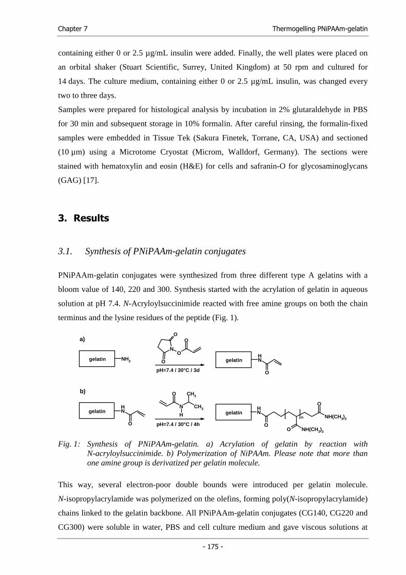
Chapter 7 Thermogelling PNiPAAm-gelatin
- 175 -
containing either 0 or 2.5 µg/mL insulin were added. Finally, the well plates were placed on
an orbital shaker (Stuart Scientific, Surrey, United Kingdom) at 50 rpm and cultured for
14 days. The culture medium, containing either 0 or 2.5 µg/mL insulin, was changed every
two to three days.
Samples were prepared for histological analysis by incubation in 2% glutaraldehyde in PBS
for 30 min and subsequent storage in 10% formalin. After careful rinsing, the formalin-fixed
samples were embedded in Tissue Tek (Sakura Finetek, Torrane, CA, USA) and sectioned
(10 µm) using a Microtome Cryostat (Microm, Walldorf, Germany). The sections were
stained with hematoxylin and eosin (H&E) for cells and safranin-O for glycosaminoglycans
(GAG) [17].
3. Results
3.1. Synthesis of PNiPAAm-gelatin conjugates
PNiPAAm-gelatin conjugates were synthesized from three different type A gelatins with a
bloom value of 140, 220 and 300. Synthesis started with the acrylation of gelatin in aqueous
solution at pH 7.4. N-Acryloylsuccinimide reacted with free amine groups on both the chain
terminus and the lysine residues of the peptide (Fig. 1).
NH2gelatin NH
O
gelatin
NH
O
gelatin
O
N
H
CH3
CH3
pH=7.4 / 30°C / 4h
N
O
O
O
O
pH=7.4 / 30°C / 3d
NH
OO NH(CH3)2
NH(CH3)2
O
n gelatin
a)
b)
Fig. 1: Synthesis of PNiPAAm-gelatin. a) Acrylation of gelatin by reaction with N-acryloylsuccinimide. b) Polymerization of NiPAAm. Please note that more than one amine group is derivatized per gelatin molecule.
This way, several electron-poor double bounds were introduced per gelatin molecule.
N-isopropylacrylamide was polymerized on the olefins, forming poly(N-isopropylacrylamide)
chains linked to the gelatin backbone. All PNiPAAm-gelatin conjugates (CG140, CG220 and
CG300) were soluble in water, PBS and cell culture medium and gave viscous solutions at
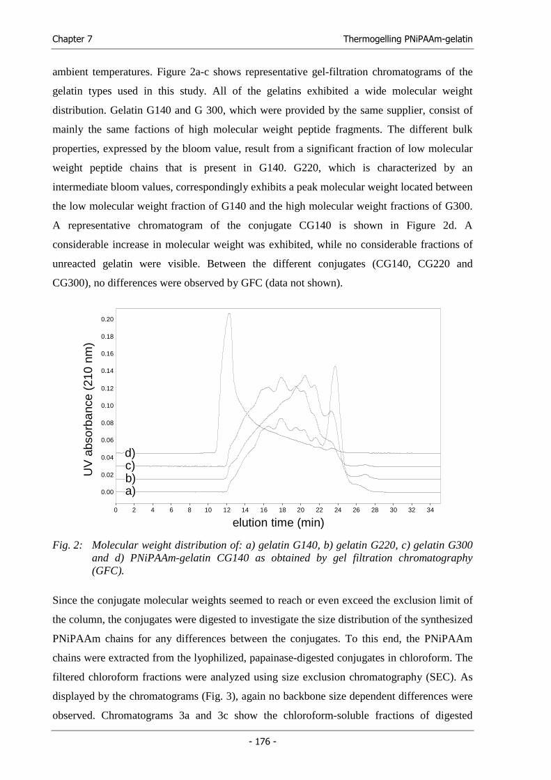
Chapter 7 Thermogelling PNiPAAm-gelatin
- 176 -
ambient temperatures. Figure 2a-c shows representative gel-filtration chromatograms of the
gelatin types used in this study. All of the gelatins exhibited a wide molecular weight
distribution. Gelatin G140 and G 300, which were provided by the same supplier, consist of
mainly the same factions of high molecular weight peptide fragments. The different bulk
properties, expressed by the bloom value, result from a significant fraction of low molecular
weight peptide chains that is present in G140. G220, which is characterized by an
intermediate bloom values, correspondingly exhibits a peak molecular weight located between
the low molecular weight fraction of G140 and the high molecular weight fractions of G300.
A representative chromatogram of the conjugate CG140 is shown in Figure 2d. A
considerable increase in molecular weight was exhibited, while no considerable fractions of
unreacted gelatin were visible. Between the different conjugates (CG140, CG220 and
CG300), no differences were observed by GFC (data not shown).
Minutes0 2 4 6 8 10 12 14 16 18 20 22 24 26 28 30 32 34
Vol
ts
0.00
0.02
0.04
0.06
0.08
0.10
0.12
0.14
0.16
0.18
0.20
UV
abs
orba
nce
(210
nm
)
elution time (min)
a)b)c)d)
Fig. 2: Molecular weight distribution of: a) gelatin G140, b) gelatin G220, c) gelatin G300 and d) PNiPAAm-gelatin CG140 as obtained by gel filtration chromatography (GFC).
Since the conjugate molecular weights seemed to reach or even exceed the exclusion limit of
the column, the conjugates were digested to investigate the size distribution of the synthesized
PNiPAAm chains for any differences between the conjugates. To this end, the PNiPAAm
chains were extracted from the lyophilized, papainase-digested conjugates in chloroform. The
filtered chloroform fractions were analyzed using size exclusion chromatography (SEC). As
displayed by the chromatograms (Fig. 3), again no backbone size dependent differences were
observed. Chromatograms 3a and 3c show the chloroform-soluble fractions of digested
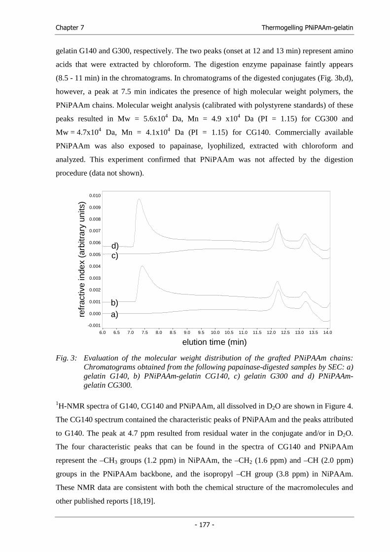
Chapter 7 Thermogelling PNiPAAm-gelatin
- 177 -
gelatin G140 and G300, respectively. The two peaks (onset at 12 and 13 min) represent amino
acids that were extracted by chloroform. The digestion enzyme papainase faintly appears
(8.5 - 11 min) in the chromatograms. In chromatograms of the digested conjugates (Fig. 3b,d),
however, a peak at 7.5 min indicates the presence of high molecular weight polymers, the
PNiPAAm chains. Molecular weight analysis (calibrated with polystyrene standards) of these
peaks resulted in Mw = 5.6x10⁴ Da, Mn = 4.9 x10⁴ Da (PI = 1.15) for CG300 and
Mw = 4.7x10⁴ Da, Mn = 4.1x10⁴ Da (PI = 1.15) for CG140. Commercially available
PNiPAAm was also exposed to papainase, lyophilized, extracted with chloroform and
analyzed. This experiment confirmed that PNiPAAm was not affected by the digestion
procedure (data not shown).
Minutes6.0 6.5 7.0 7.5 8.0 8.5 9.0 9.5 10.0 10.5 11.0 11.5 12.0 12.5 13.0 13.5 14.0
Vol
ts
-0.001
0.000
0.001
0.002
0.003
0.004
0.005
0.006
0.007
0.008
0.009
0.010
refr
activ
e in
dex
(arb
itrar
y un
its)
elution time (min)
a)b)
c)d)
Fig. 3: Evaluation of the molecular weight distribution of the grafted PNiPAAm chains: Chromatograms obtained from the following papainase-digested samples by SEC: a) gelatin G140, b) PNiPAAm-gelatin CG140, c) gelatin G300 and d) PNiPAAm-gelatin CG300.
1H-NMR spectra of G140, CG140 and PNiPAAm, all dissolved in D2O are shown in Figure 4.
The CG140 spectrum contained the characteristic peaks of PNiPAAm and the peaks attributed
to G140. The peak at 4.7 ppm resulted from residual water in the conjugate and/or in D2O.
The four characteristic peaks that can be found in the spectra of CG140 and PNiPAAm
represent the –CH3 groups (1.2 ppm) in NiPAAm, the –CH2 (1.6 ppm) and –CH (2.0 ppm)
groups in the PNiPAAm backbone, and the isopropyl –CH group (3.8 ppm) in NiPAAm.
These NMR data are consistent with both the chemical structure of the macromolecules and
other published reports [18,19].
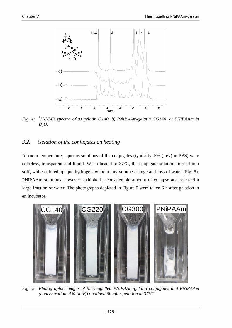
Chapter 7 Thermogelling PNiPAAm-gelatin
- 178 -
01234567(ppm)
a)
b)
c)
H2O 132 4
O
n
NH
HH
H
H
HHH
HHH
1111
11
2
34
O
n
NH
HH
H
H
HHH
HHH
1111
11
2
34
Fig. 4: 1H-NMR spectra of a) gelatin G140, b) PNiPAAm-gelatin CG140, c) PNiPAAm in D2O.
3.2. Gelation of the conjugates on heating
At room temperature, aqueous solutions of the conjugates (typically: 5% (m/v) in PBS) were
colorless, transparent and liquid. When heated to 37°C, the conjugate solutions turned into
stiff, white-colored opaque hydrogels without any volume change and loss of water (Fig. 5).
PNiPAAm solutions, however, exhibited a considerable amount of collapse and released a
large fraction of water. The photographs depicted in Figure 5 were taken 6 h after gelation in
an incubator.
CG140CG140 CG220CG220 CG300CG300 PNiPAAmPNiPAAm
Fig. 5: Photographic images of thermogelled PNiPAAm-gelatin conjugates and PNiPAAm (concentration: 5% (m/v)) obtained 6h after gelation at 37°C.
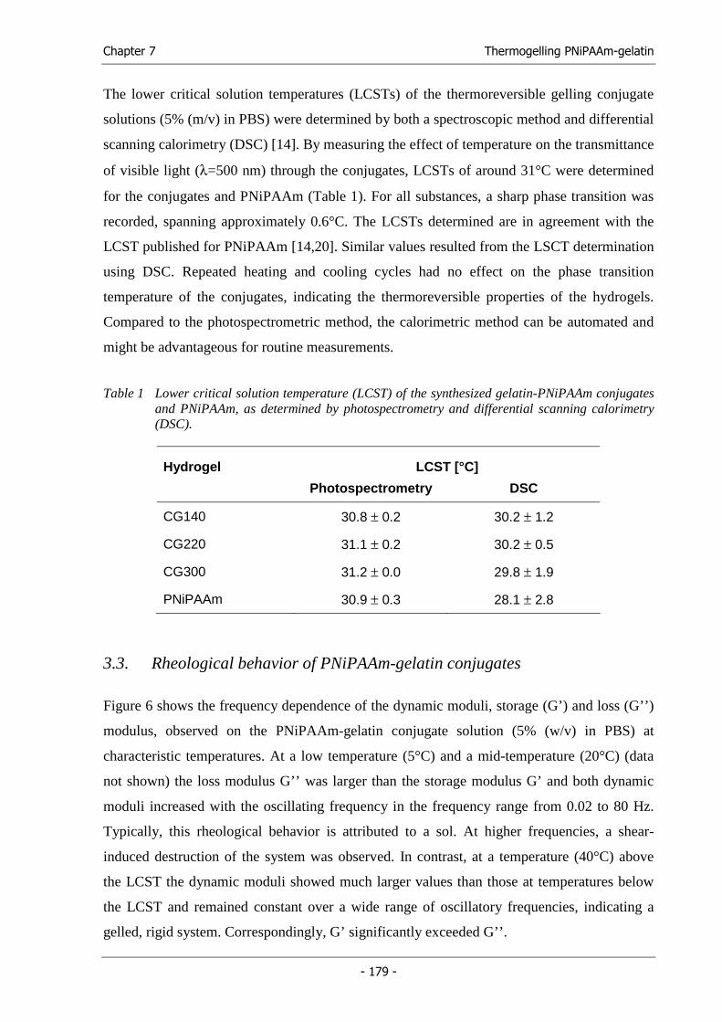
Chapter 7 Thermogelling PNiPAAm-gelatin
- 179 -
The lower critical solution temperatures (LCSTs) of the thermoreversible gelling conjugate
solutions (5% (m/v) in PBS) were determined by both a spectroscopic method and differential
scanning calorimetry (DSC) [14]. By measuring the effect of temperature on the transmittance
of visible light (λ=500 nm) through the conjugates, LCSTs of around 31°C were determined
for the conjugates and PNiPAAm (Table 1). For all substances, a sharp phase transition was
recorded, spanning approximately 0.6°C. The LCSTs determined are in agreement with the
LCST published for PNiPAAm [14,20]. Similar values resulted from the LSCT determination
using DSC. Repeated heating and cooling cycles had no effect on the phase transition
temperature of the conjugates, indicating the thermoreversible properties of the hydrogels.
Compared to the photospectrometric method, the calorimetric method can be automated and
might be advantageous for routine measurements.
Table 1 Lower critical solution temperature (LCST) of the synthesized gelatin-PNiPAAm conjugates and PNiPAAm, as determined by photospectrometry and differential scanning calorimetry (DSC).
Hydrogel LCST [°C]
Photospectrometry DSC
CG140 30.8 ± 0.2 30.2 ± 1.2
CG220 31.1 ± 0.2 30.2 ± 0.5
CG300 31.2 ± 0.0 29.8 ± 1.9
PNiPAAm 30.9 ± 0.3 28.1 ± 2.8
3.3. Rheological behavior of PNiPAAm-gelatin conjugates
Figure 6 shows the frequency dependence of the dynamic moduli, storage (G’) and loss (G’’)
modulus, observed on the PNiPAAm-gelatin conjugate solution (5% (w/v) in PBS) at
characteristic temperatures. At a low temperature (5°C) and a mid-temperature (20°C) (data
not shown) the loss modulus G’’ was larger than the storage modulus G’ and both dynamic
moduli increased with the oscillating frequency in the frequency range from 0.02 to 80 Hz.
Typically, this rheological behavior is attributed to a sol. At higher frequencies, a shear-
induced destruction of the system was observed. In contrast, at a temperature (40°C) above
the LCST the dynamic moduli showed much larger values than those at temperatures below
the LCST and remained constant over a wide range of oscillatory frequencies, indicating a
gelled, rigid system. Correspondingly, G’ significantly exceeded G’’.
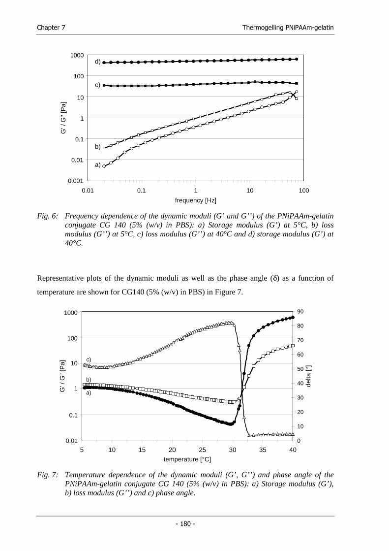
Chapter 7 Thermogelling PNiPAAm-gelatin
- 180 -
0,001
0,01
0,1
1
10
100
1000
0,01 0,1 1 10 100
frequency [Hz]
G' /
G''
[Pa]
a)
b)
c)
d)1000
100
10
1
0.1
0.01
0.001
0.01 0.1 1 10 100
Fig. 6: Frequency dependence of the dynamic moduli (G’ and G’’) of the PNiPAAm-gelatin conjugate CG 140 (5% (w/v) in PBS): a) Storage modulus (G’) at 5°C, b) loss modulus (G’’) at 5°C, c) loss modulus (G’’) at 40°C and d) storage modulus (G’) at 40°C.
Representative plots of the dynamic moduli as well as the phase angle (δ) as a function of
temperature are shown for CG140 (5% (w/v) in PBS) in Figure 7.
0,01
0,1
1
10
100
1000
5 10 15 20 25 30 35 40temperature [°C]
G' /
G''
[Pa]
0
10
20
30
40
50
60
70
80
90de
lta [°
]
c)
b)
a)
1000
100
10
1
0.1
0.01
Fig. 7: Temperature dependence of the dynamic moduli (G’, G’’) and phase angle of the PNiPAAm-gelatin conjugate CG 140 (5% (w/v) in PBS): a) Storage modulus (G’), b) loss modulus (G’’) and c) phase angle.
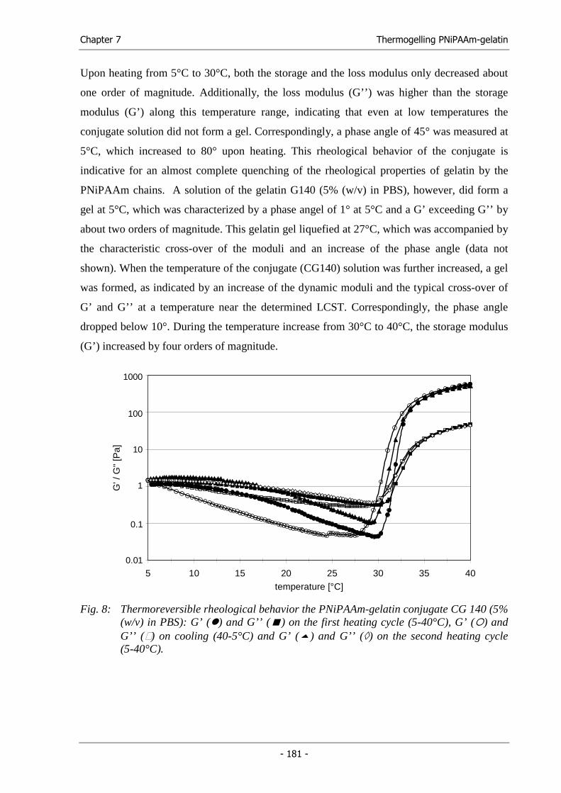
Chapter 7 Thermogelling PNiPAAm-gelatin
- 181 -
Upon heating from 5°C to 30°C, both the storage and the loss modulus only decreased about
one order of magnitude. Additionally, the loss modulus (G’’) was higher than the storage
modulus (G’) along this temperature range, indicating that even at low temperatures the
conjugate solution did not form a gel. Correspondingly, a phase angle of 45° was measured at
5°C, which increased to 80° upon heating. This rheological behavior of the conjugate is
indicative for an almost complete quenching of the rheological properties of gelatin by the
PNiPAAm chains. A solution of the gelatin G140 (5% (w/v) in PBS), however, did form a
gel at 5°C, which was characterized by a phase angel of 1° at 5°C and a G’ exceeding G’’ by
about two orders of magnitude. This gelatin gel liquefied at 27°C, which was accompanied by
the characteristic cross-over of the moduli and an increase of the phase angle (data not
shown). When the temperature of the conjugate (CG140) solution was further increased, a gel
was formed, as indicated by an increase of the dynamic moduli and the typical cross-over of
G’ and G’’ at a temperature near the determined LCST. Correspondingly, the phase angle
dropped below 10°. During the temperature increase from 30°C to 40°C, the storage modulus
(G’) increased by four orders of magnitude.
0,01
0,1
1
10
100
1000
5 10 15 20 25 30 35 40
temperature [°C]
G' /
G''
[Pa]
1000
100
10
1
0.1
0.01
Fig. 8: Thermoreversible rheological behavior the PNiPAAm-gelatin conjugate CG 140 (5% (w/v) in PBS): G’ ( ) and G’’ ( ) on the first heating cycle (5-40°C), G’ ( ) and G’’ ( ) on cooling (40-5°C) and G’ ( ) and G’’ (◊) on the second heating cycle (5-40°C).
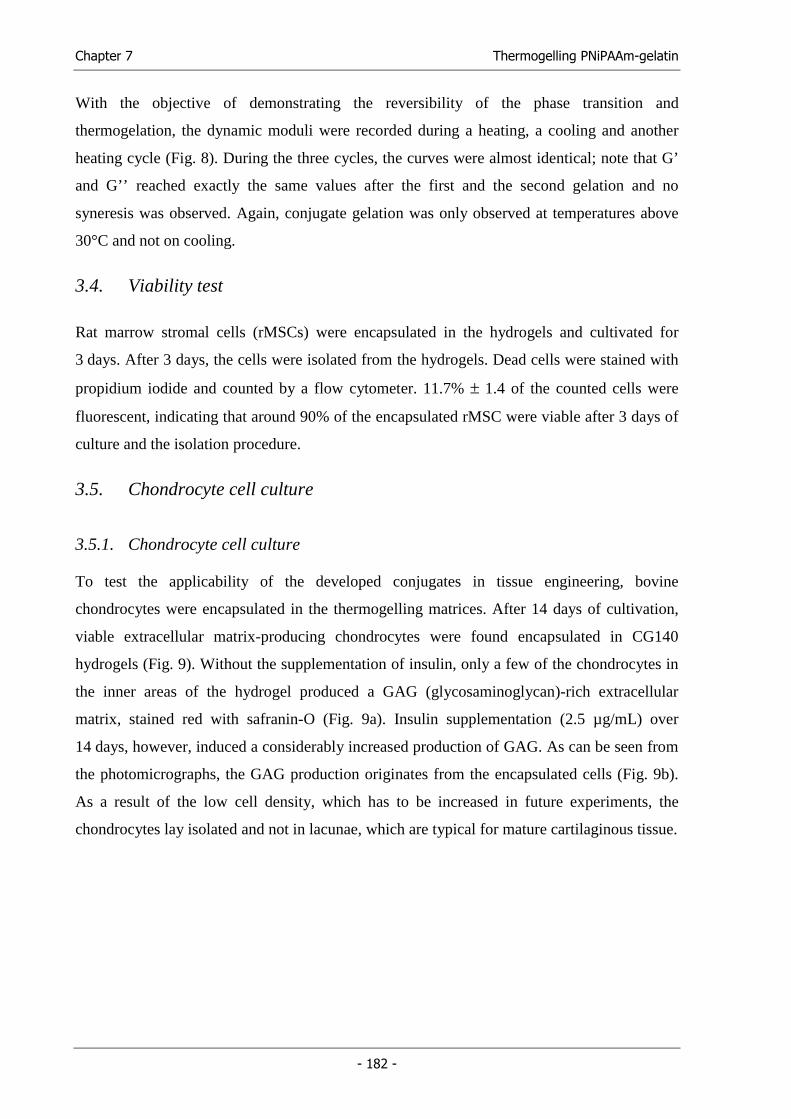
Chapter 7 Thermogelling PNiPAAm-gelatin
- 182 -
With the objective of demonstrating the reversibility of the phase transition and
thermogelation, the dynamic moduli were recorded during a heating, a cooling and another
heating cycle (Fig. 8). During the three cycles, the curves were almost identical; note that G’
and G’’ reached exactly the same values after the first and the second gelation and no
syneresis was observed. Again, conjugate gelation was only observed at temperatures above
30°C and not on cooling.
3.4. Viability test
Rat marrow stromal cells (rMSCs) were encapsulated in the hydrogels and cultivated for
3 days. After 3 days, the cells were isolated from the hydrogels. Dead cells were stained with
propidium iodide and counted by a flow cytometer. 11.7% ± 1.4 of the counted cells were
fluorescent, indicating that around 90% of the encapsulated rMSC were viable after 3 days of
culture and the isolation procedure.
3.5. Chondrocyte cell culture
3.5.1. Chondrocyte cell culture
To test the applicability of the developed conjugates in tissue engineering, bovine
chondrocytes were encapsulated in the thermogelling matrices. After 14 days of cultivation,
viable extracellular matrix-producing chondrocytes were found encapsulated in CG140
hydrogels (Fig. 9). Without the supplementation of insulin, only a few of the chondrocytes in
the inner areas of the hydrogel produced a GAG (glycosaminoglycan)-rich extracellular
matrix, stained red with safranin-O (Fig. 9a). Insulin supplementation (2.5 µg/mL) over
14 days, however, induced a considerably increased production of GAG. As can be seen from
the photomicrographs, the GAG production originates from the encapsulated cells (Fig. 9b).
As a result of the low cell density, which has to be increased in future experiments, the
chondrocytes lay isolated and not in lacunae, which are typical for mature cartilaginous tissue.
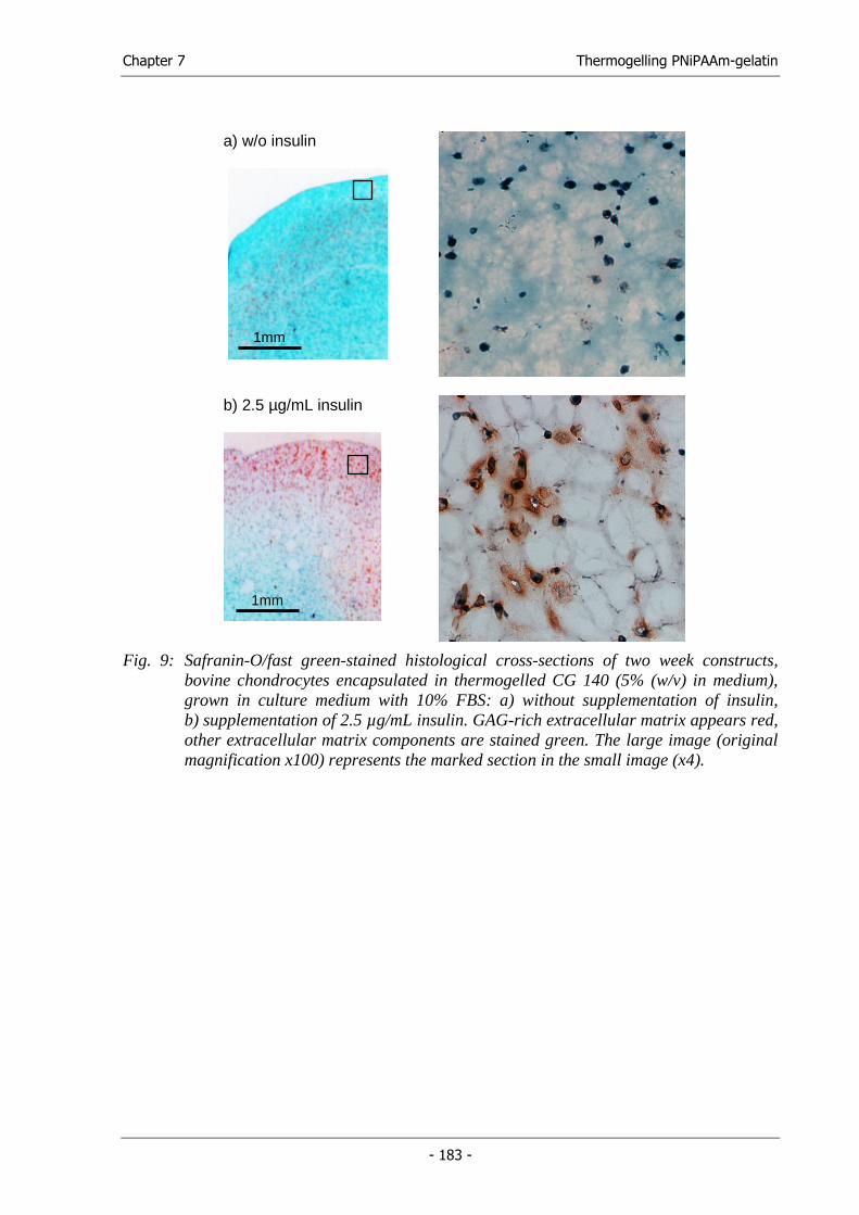
Chapter 7 Thermogelling PNiPAAm-gelatin
- 183 -
a) w/o insulin
b) 2.5 µg/mL insulin
Fig. 9: Safranin-O/fast green-stained histological cross-sections of two week constructs, bovine chondrocytes encapsulated in thermogelled CG 140 (5% (w/v) in medium), grown in culture medium with 10% FBS: a) without supplementation of insulin, b) supplementation of 2.5 µg/mL insulin. GAG-rich extracellular matrix appears red, other extracellular matrix components are stained green. The large image (original magnification x100) represents the marked section in the small image (x4).
1mm
1mm
Chapter 7 Thermogelling PNiPAAm-gelatin
- 184 -
4. Discussion
With the objective of developing an injectable extracellular matrix (ECM) substitute, we
synthesized a conjugate of gelatin, a protein derived from the natural extracellular matrix
protein collagen, and poly(N-isopropylacrylamide) (PNiPAAm), a polymer offering unique
thermoresponsive phase transition characteristics with a LCST slightly below body
temperature. Hoffman and co-workers first applied PNiPAAm-based polymers to injectable
drug delivery systems and other functional matrices for biomedical applications [6,21-23]. By
copolymerization with other polymers, several thermogelling biomaterials for cell
encapsulation were developed [9,10]. Gelatin, the other component of the conjugate, is known
as a cell adhesive matrix but is soluble in water at physiological temperature. Therefore,
various insolubilization techniques, mainly crosslinking procedures, have been applied to
make use of gelatin as an ECM substitute in tissue engineering devices [24-26]. Evidently,
these techniques are often not suitable to in vivo gelation due to the toxicity of the available
crosslinking agents. Ideally, the grafting of PNiPAAm chains to a gelatin backbone would
change the rheological properties of gelatin in such a way that gelation of conjugate solutions
occurs on heating and not on cooling, which would be typical for gelatin hydrogels.
Additionally, the gelatin backbone would support the formation of a stable, non-shrinking
hydrogel, as linear PNiPAAm hydrogels alone collapse at body temperature [20]. Two other
research groups have recently synthesized similar conjugates [10,27,28]. Matsuda and co-
workers synthesized PNiPAAm-gelatin conjugates from a multiply derivatized
dithiocarbamylated low molecular weight gelatin (9.5x10⁴ Da) by iniferter-based
photopolymerization. They successfully employed their conjugates as a matrix for cartilage
tissue engineering [29,30]. Cell viability inside these conjugates strongly depended on the
concentration of PNiPAAm-gelatin and the molecular weight of the PNiPAAm graft chain.
Acceptable viability was only found for a gel prepared at low concentration (5%) of the
conjugate with high molecular weight PNiPAAm graft chains (1.3x10⁵ Da) [29]. Yoshioka et
al. synthesized the conjugate from acrylated gelatin by a thermally induced polymerization of
NiPAAm that is similar to our approach. The resulting conjugate demonstrated gelation upon
either heating or cooling. Unfortunately, no information was provided on the molecular
weight of the gelatin used and the synthesized conjugate [27].
Based on the synthesis described by Yoshioka et al., we synthesized PNiPAAm-gelatin
conjugates from high molecular weight type A gelatins (Fig. 2). The investigated gelatin types
showed a broad molecular weight distribution, characteristic for gelatin, with an onset
Chapter 7 Thermogelling PNiPAAm-gelatin
- 185 -
retention time of 12 min, corresponding to a molecular weight (Mw) of more than 4x10⁵ Da.
While no details are provided in the literature concerning the pH, we kept the pH at 7.4 during
acrylation and polymerization by using phosphate buffer as the reaction medium. The
synthesis led to high molecular weight conjugates of about 106 Da or more. For a more
detailed analysis of the conjugates, the molecular weight of the grafted PNiPAAm chains was
investigated after conjugate digestion with papainase. This procedure allows for the
characterization of the PNiPAAm chains that had been formed at the gelatin backbone under
the conditions of conjugate preparation. To our knowledge, no other author has performed this
characterization step in connection to these conjugates. Molecular weights of approx.
5x10⁴ Da were determined for PNiPAAm, similar to those obtained by Ibusuki et al. [29,31].
The theoretical gelatin content of the conjugates was 28.6% (CG140) and 25% (CG220,
CG300). This gelatin content seems to be sufficient for e.g. cartilage tissue engineering, since
a successful product with a similar gelatin content was described in the literature [30,31].
The PNiPAAm-gelatin conjugates exhibited a LCST of around 31°C (Table 1) and formed
form-filling, stiff hydrogels at physiological temperature without any loss of water (Fig. 5).
Figure 5 also depicts the collapse of a hydrogel formed by linear PNiPAAm chains of similar
molecular weight as the grafted chains. Similar phenomena were observed for crosslinked
PNiPAAm-gelatin conjugates or mixtures of gelatin and PNiPAAm (data not shown). In
contrast to PNIPAAm, complete precipitation was not obtained for the developed high
molecular weight PNiPAAm-gelatin conjugates, suggesting that, although PNiPAAm chains
collapsed at temperatures above LCST, gelatin molecules appeared to hinder intramolecular
aggregation, thus avoiding the complete precipitation in the diluted state at the investigated
concentration (5% (w/v)).
The rheological characterization of the synthesized conjugates revealed that the gelatin is
ideally masked by the grafted PNiPAAm chains. Using oscillating rheological measurements,
the real and imaginary parts, G’ and G’’, as well as the phase angle of the complex shear
modulus are examined. The observed G’ and G’’ represent the elasticity term and the
viscosity term of the material at the oscillatory frequency. A solution of CG140 (5% (w/v) in
PBS) was a viscoelastic fluid (G’ < G’’ and δ > 45°) at temperatures below the LCST (Fig. 6
and 7). At temperatures above the LCST, it behaved as viscoelastic solid (G’ > G’’ and
δ < 45°). In other words, the PNiPAAm-gelatin conjugate perfectly fulfills the demands on an
injectable cell and/or drug carrier. At low temperatures, conjugate solutions formed a viscous
liquid that can be easily mixed with cells in suspensions or dissolved drugs. The moldable
liquids can be injected and quickly form a rigid gel at body temperature without any loss of
Chapter 7 Thermogelling PNiPAAm-gelatin
- 186 -
water. The perfect reversibility of this phase transition behavior was shown for the
synthesized conjugates by rheological measurements and DSC. In no other study we did find
this exact reversibility of gelation, highlighting the purity of the product.
Since the developed conjugates offered the desired gelation characteristics, cell encapsulation
experiments were conducted to assess the cytocompatibility of the conjugates and the gelation
procedure. A viability of around 90% was found for rat mesenchymal stromal cells (rMSCs)
after encapsulation in the synthesized conjugates for 3 days. As described in the literature, any
cytotoxic effect of the matrix would have become visible within the first 3 days [28].
In order to finally test the applicability of the developed conjugates as cell carriers for tissue
engineering applications, we encapsulated bovine chondrocytes and cultured them under
conditions that have been shown to support cartilage formation on polymeric fiber meshes
[32]. To stimulate extracellular matrix formation and to check for the biochemical activity of
the cells, insulin was supplemented to some cultures. Generally, no cytotoxic effects were
observed over the cultivation time of 14 days. Moreover, exogenous insulin stimulated GAG
formation, indicating that the encapsulated chondrocytes maintained differentiation and
biological function. Obviously, a much higher cell density is required to engineer coherent
tissues. Nevertheless, the PNiPAAm-gelatin conjugates demonstrated great potential for their
use as injectable ECM substitutes for tissue engineering applications.
Generally, a variety of applications for injectable extracellular matrix substitutes can be
imagined in the field of tissue engineering. These hydrogels may serve as cell carriers for the
engineering of several soft tissues, such as skin or adipose tissue, or even cartilage and bone
tissue. In combination with suitable growth factors, injectable ECM substitutes can be
designed as biomimetic matrices that promote and guide nerve regeneration or
neovascularization of large defects. Furthermore, the micrometer-scale pore network of
polymeric cell carriers (scaffolds) can be filled with the injectable, artificial ECM. This way,
the nanofibrous structure of the gel-forming conjugate molecules mimics the natural
nanoscale interactions between cells and extracellular matrix proteins, while the scaffold
provides additional mechanical strength.
Chapter 7 Thermogelling PNiPAAm-gelatin
- 187 -
5. Conclusion
In this study, PNiPAAm-gelatin conjugates were synthesized from several type A gelatins in a
two-step reaction. The resulting high molecular weight conjugates underwent
thermoreversible gelation upon heating above their LCST, which was determined by
photospectrometry and DSC. Oscillating rheological measurements were employed to
investigate this phase separation and gelling behavior. Finally, high cell viability in the
hydrogels was demonstrated for mesenchymal stromal cells. Chondrocytes that were
encapsulated in the conjugates could be stimulated for GAG production over 14 days.
Altogether, the developed conjugates are promising ECM substitutes for many tissue
engineering applications.
6. Acknowledgements
The authors like to thank Joerg Tessmar and Antonios G. Mikos (Department of
Bioengineering, Rice University, Houston, Texas, USA) for placing the oscillating rheometer
at our disposal.
Chapter 7 Thermogelling PNiPAAm-gelatin
- 188 -
7. References
(1) Ye Q, Zund G, Benedikt P, Jockenhoevel S, Hoerstrup SP, Sakyama S, Hubbell JA, Turina M. 'Fibrin gel as a three dimensional matrix in cardiovascular tissue engineering'. Eur J Cardiothorac Surg (2000); 17: 587-591.
(2) Tabata Y, Miyao M, Ozeki M, Ikada Y. 'Controlled release of vascular endothelial growth factor by use of collagen hydrogels'. J Biomater Sci , Polym Ed (2000); 11: 915-930.
(3) Cummings CL, Gawlitta D, Nerem RM, Stegemann JP. 'Properties of engineered vascular constructs made from collagen, fibrin, and collagen-fibrin mixtures'. Biomaterials (2004); 25: 3699-3706.
(4) Geiger M, Li RH, Friess W. 'Collagen sponges for bone regeneration with rhBMP-2'. Adv Drug Delivery Rev (2003); 55: 1613-1629.
(5) Friess W. 'Collagen in drug delivery and tissue engineering'. Adv Drug Delivery Rev (2003); 55: 1529-1530.
(6) Hoffman AS. 'Hydrogels for biomedical applications'. Adv Drug Delivery Rev (2002); 54: 3-12.
(7) Temenoff JS, Mikos AG. 'Injectable biodegradable materials for orthopedic tissue engineering'. Biomaterials (2000); 21: 2405-2412.
(8) Gutowska A, Jeong B, Jasionowski M. 'Injectable gels for tissue engineering'. Anat Rec (2001); 263: 342-349.
(9) Stile RA, Burghardt WR, Healy KE. 'Synthesis and characterization of injectable poly(N-isopropylacrylamide)-based hydrogels that support tissue formation in vitro'. Macromolecules (1999); 32: 7370-7379.
(10) Ohya S, Nakayama Y, Matsuda T. 'Thermoresponsive artificial extracellular matrix for tissue engineering: Hyaluronic acid bioconjugated with poly(N-isopropylacrylamide) grafts'. Biomacromolecules (2001); 2: 856-863.
(11) Sela M, Arnon R. 'Studies on the chemical basis of the antigenicity of proteins. I. Antigenicity of polypeptide gelatins'. Biochem J (1960); 75: 91-103.
(12) Guilmet D, Bachet J, Goudot B, Laurian C, Gigou F, Bical O, Barbagelatta M. 'Use of biological glue in acute aortic dissection. Preliminary clinical results with a new surgical technique'. J Thorac Cardiovasc Surg (1979); 77: 516-521.
(13) Kang HW, Tabata Y, Ikada Y. 'Fabrication of porous gelatin scaffolds for tissue engineering'. Biomaterials (1999); 20: 1339-1344.
(14) Schild HG, Tirrell DA. 'Microcalorimetric detection of lower critical solution temperatures in aqueous polymer solutions'. J Phys Chem (1990); 94: 4352-4356.
Chapter 7 Thermogelling PNiPAAm-gelatin
- 189 -
(15) Lieb E, Tessmar J, Hacker M, Fischbach C, Rose D, Blunk T, Mikos AG, Goepferich A, Schulz MB. 'Poly(D,L-lactic acid)-Poly(ethylene glycol)-Monomethyl Ether Diblock Copolymers Control Adhesion and Osteoblastic Differentiation of Marrow Stromal Cells'. Tissue Eng (2003); 9: 71-84.
(16) Freed LE, Marquis JC, Nohria A, Emmanual J, Mikos AG, Langer R. 'Neocartilage formation in vitro and in vivo using cells cultured on synthetic biodegradable polymers'. J Biomed Mater Res (1993); 27: 11-23.
(17) Lillie RD, Fullmer HM. Histopathologic techniques and practical histochemistry. New York: McGraw Hill, 1976.
(18) Rodin VV, Izmailova VN. 'NMR method in the study of the interfacial adsorption layer of gelatin'. Colloids Surf A (1996); 106: 95-102.
(19) Wang LQ, Tu K, Li Y, Zhang J, Jiang L, Zhang Z. 'Synthesis and characterization of temperature responsive graft copolymers of dextran with poly(N-isopropylacrylamide)'. Reactive and Functional Polymers (2002); 53: 19-27.
(20) Chen G, Hoffman AS. 'Graft copolymers that exhibit temperature-induced phase transitions over a wide range of pH'. Nature (1995); 373: 49-52.
(21) Dong Lc, Hoffman AS. 'Synthesis and application of thermally reversible heterogels for drug delivery'. J Control Release (1990); 13: 21-31.
(22) Miura M, Cole CA, Monji N, Hoffman AS. 'Temperature-dependent absorption/desorption behavior of lower critical solution temperature (LCST) polymers on various substrates'. J Biomater Sci , Polym Ed (1994); 5: 555-568.
(23) Chen G, Hoffman AS. 'Preparation and properties of thermoreversible, phase-separating enzyme-oligo(N-isopropylacrylamide) conjugates'. Bioconjug Chem (1993); 4: 509-514.
(24) Sung HW, Huang DM, Chang WH, Huang RN, Hsu JC. 'Evaluation of gelatin hydrogel crosslinked with various crosslinking agents as bioadhesives: in vitro study'. J Biomed Mater Res (1999); 46: 520-530.
(25) Choi YS, Hong SR, Lee YM, Song KW, Park MH, Nam YS. 'Studies on gelatin-containing artificial skin: II. Preparation and characterization of cross-linked gelatin-hyaluronate sponge'. J Biomed Mater Res (1999); 48: 631-639.
(26) Ito A, Mase A, Takizawa Y, Shinkai M, Honda H, Hata KI, Ueda M, Kobayashi T. 'Transglutaminase-mediated gelatin matrices incorporating cell adhesion factors as a biomaterial for tissue engineering'. J Biosci Bioeng (2003); 95: 196-199.
(27) Yoshioka H, Mori Y, Tsukikawa S, Kubota S. 'Thermoreversible gelation on cooling and on heating of an aqueous gelatin-poly(N-isopropylacrylamide) conjugate'. Polym Adv Technol (1998); 9: 155-158.
(28) Ohya S, Nakayama Y, Matsuda T. 'Material design for an artificial extracellular matrix: cell entrapment in poly (N-isopropylacrylamide) (PNIPAM)-grafted gelatin hydrogel'. Artif Organs (2001); 4: 308-314.
Chapter 7 Thermogelling PNiPAAm-gelatin
- 190 -
(29) Ibusuki S, Fujii Y, Iwamoto Y, Matsuda T. 'Tissue-engineered cartilage using an injectable and in situ gelable thermoresponsive gelatin: fabrication and in vitro performance'. Tissue Eng (2003); 9: 371-384.
(30) Ibusuki S, Iwamoto Y, Matsuda T. 'System-Engineered Cartilage Using Poly(N-isopropylacrylamide)-Grafted Gelatin as in Situ-Formable Scaffold: In Vivo Performance'. Tissue Eng (2003); 9: 1133-1142.
(31) Morikawa N, Matsuda T. 'Thermoresponsive artificial extracellular matrix: N-isopropylacrylamide-graft-copolymerized gelatin'. J Biomater Sci , Polym Ed (2002); 13: 167-183.
(32) Kellner K, Schulz MB, Gopferich A, Blunk T. 'Insulin in tissue engineering of cartilage: A potential model system for growth factor application'. J Drug Targeting (2001); 9: 439-448.

Fabrication of Functional Cell Carriers
Chapter 8
Summary and
Conclusions

Chapter 8 Summary and Conclusions
- 193 -
1. Summary
Cell carriers (scaffolds) play a pivotal role in attempts to engineer living tissues from isolated
cells for tissue reconstruction and basic research. In these attempts, cell carriers serve as an
artificial extracellular matrix that accommodates mammalian cells and guides their growth,
differentiation and tissue development in three dimensions [1]. Generally, an appropriate cell
carrier is designed to mimic the cell’s natural environment. Thus, the scaffolding material and
architecture differ according to the tissue type [2]. The appropriate scaffolds for
musculoskeletal tissue, bone and cartilage are preferably made from ceramics, metals or
lipophilic polymers to obtain sufficient mechanical stability. Conversely, hydrophilic, gel-
forming polymers are widely used as extracellular matrix substitutes for cell encapsulation
and the engineering of soft tissue [3]. For the design of functional, biomimetic cell carriers,
both material concepts are of interest and addressed in this thesis.
This work focused primarily on the fabrication of functional, macroporous cell carriers from
biodegradable polymers. Several important design criteria and characteristics have been
identified for such scaffolds during the last decade. Ideally, the scaffolds should: (i) be three-
dimensional and highly porous with an interconnected pore network for cell growth and flow
transport of nutrients and metabolic waste; (ii) be biocompatible and resorbable with
controllable degradation and resorption rates to match cell/tissue growth in vitro and/or in
vivo; (iii) have a suitable surface chemistry for cell attachment, proliferation, and
differentiation and (iv) have mechanical properties to match those of the tissues at the site of
implantation [4].
The design of a functional scaffold starts with the selection of the appropriate scaffolding
material. In light of the enormous number of biodegradable polymers that have been
developed and characterized so far, it might be relatively simple to find an ideal material in
terms of mechanical properties and degradation kinetics. The surface chemistry of these
polymers, however, is far from optimal. The major concern is that the interaction of these
lipophilic polymers with the surrounding biological environment may lead to the non-
selective adsorption of proteins. This process in turn triggers a number of non-specific cellular
responses and may lead to uncontrollable tissue development and growth [5]. To overcome
these limitations, biodegradable polymers were recently developed that contain a hydrophilic
polymer block to suppress the adsorption of proteins and a linker molecule activated for
reaction with biologically active molecules, such as adhesion peptides or growth factors [6].
Chapter 8 Summary and Conclusions
- 194 -
These biodegradable, activated diblock copolymers are promising materials for the fabrication
of cell carriers with a biomimetic surface design. Furthermore, polymer degradability and
mechanical properties can be varied and adapted to different types of tissue by altering the
copolymer ratio and crystallinity of the lipophilic block. Using two different bifunctional
linkers, namely disuccinimidyl tartrate and N-succinimidyl 3-maleinimido propionate, which
were covalently attached to monoamine poly(ethylene glycol)-block-poly(D,L-lactic acid)
(H2N-PEG-PLA), amine-reactive (ST-NH-PEG-PLA) and thiol-reactive diblock copolymers
(MP-NH-PEG-PLA) were recently synthesized and their functionality was demonstrated
using fluorescent dyes and model proteins containing free amine or thiol groups [6,7].
The first objective towards the fabrication of functional cell carriers was to affect cell
adhesion to these reactive diblock copolymers by covalently attaching adhesion-mediating
peptides (Chapter 2). To this end, films of both amine-reactive (ST-NH-PEG2PLA20) and
thiol-reactive derivatives (MP-NH-PEG2PLA40) were modified with cyclic αvβ3/αvβ5
integrin subtype specific RGD peptides simply by incubation of the films with buffered
solutions of the peptides. A non-binding RAD peptide analogue served as a control. Human
osteoblasts, known to express these integrins, were used to determine cell-polymer
interactions. The adhesion experiments revealed that less than 20% of the seeded cells
adhered to the unmodified ST-NH-PEG2PLA20 surfaces (PEG-content: 9 %) and about 50 %
of seeded cells were found on buffer treated MP-NH-PEG2PLA40 films (PEG-content: 5%).
The adhered cells exhibited a round shape indicating only a low level of cell-biomaterial
interaction. This correlation between the PEG-content of the PEG-PLA diblock copolymers
and the amount and shape of adhered cells was consistent with the data known for marrow
stromal cells on non-reactive MeO-PEG-PLA surfaces [8,9]. On all RGD-modified polymer
films, however, the adhesion of human osteoblasts was significantly increased (up to 100%
adhesion) compared to the RAD-modified or unmodified surfaces. In addition, cells were
widely spread on the RGD-modified films, indicating strong cell-surface interactions, whereas
cells on the RAD-modified films retained their round morphology. Several control groups
proved the covalent attachment of the peptides. This study was able to demonstrate the
envisioned surface modification concept and show the biological efficacy of the instant
surface modification procedure.
To process these diblock copolymers into tissue engineering scaffolds, a suitable fabrication
technique was developed (Chapter 3). This technique had to account for the physicochemical
properties of the polymers as well as the general demands on scaffold microstructure, namely
high porosity, control of pore size and high interconnectivity. Furthermore, the absence of
Chapter 8 Summary and Conclusions
- 195 -
water during polymer processing was a key prerequisite to prevent hydrolysis of the amine-
reactive N-hydroxysuccinimide ester. To this end, an anhydrous technique was developed,
which utilizes solid lipid microparticles dispersed in the polymer solution as pore forming
devices. Simultaneous polymer precipitation and porogen extraction in warm n-hexane
generated macroporous scaffolds. The adjustment of the porogen particle’s melting point to
the polymer’s glass transition temperature was shown to be a key step in generating the
interconnected pore networks. Scaffolds from amine-reactive polymers were successfully
fabricated and, as a model protein, insulin was covalently attached to the scaffold surface in a
simple incubation procedure. The success of this experiment indicated the preservation of the
polymer’s amine-reactivity during processing. Recently, the covalent attachment of bFGF was
also demonstrated on such scaffolds. In preliminary experiments, bFGF modified scaffolds
promoted vascular ingrowth after subcutaneous implantation in nude mice. To confirm these
findings, bFGF loaded scaffolds are currently being investigated in two different in vivo
models.
For processing, the polymers were dissolved in an acetone-chloroform-mixture (65:35 (v/v))
and the triglyceride microparticles were extracted in n-hexane. According to the ICH
guidelines on residual solvents, chloroform and n-hexane are classified as class 2 solvents and
their use should be limited. A thermodynamically equivalent polymer solvent mixture of less
toxic solvents (ICH class 3) was systematically determined using Hansen Solubility
Parameters (HSPs) to eliminate chloroform from the fabrication technique without changing
other processing parameters (Chapter 4). The HSPs of a mixture containing methyl ethyl
ketone 59% (v/v) and tetrahydrofurane 41% (v/v) were found to best fit the parameters
calculated for the acetone-chloroform-mixture. Using this alternative solvent mixture and n-
heptane as an alternative extraction medium, PLGA and MeO-PEG2PLA40 were processed
into tissue engineering scaffolds without parameter changes. Moreover, the solvent exchange
had only negligible effects on the macro- and microstructure of the resulting scaffolds.
A follow-up study focused on determining the solubility parameters of PLA, PLGA and
MEO-PEG-PLA (Chapter 5). Theoretical and experimental methods, namely group
contribution methods, solubility and viscosity measurements, were employed to determine the
solubility parameters of the polymers. A two-dimensional solvent map was introduced that
allows for discrimination between solvents and non-solvents for the polymers. Viscosity
measurements provided further information on the partial polymer-solvent interactions.
In addition to the surface chemistry (Chapter 2 and 3) and biocompatibility (Chapter 4), the
architectural and mechanical properties of a cell carrier greatly influence cell proliferation,
Chapter 8 Summary and Conclusions
- 196 -
differentiation and tissue development. Control over these properties during polymer
processing is mandatory for scaffold adaptation to different applications and types of tissue.
Processing parameters that allow for the processing of various biodegradable polymers of
different compositions and molecular weights (22 - 160 kDa) were determined for the solid
lipid templating technique (SLT). Pore interconnectivity, as one important architectural
feature, was controlled by the extraction temperature and the porogen’s melting point. The
pore size of the scaffolds was controlled by the size distribution of the porogen microparticles.
During processing, the rheological behavior of the dispersion prepared from the polymer
solution and porogen microparticles, which has major influence on micro- and macrostructure
of the resulting scaffolds, was characterized by oscillating rheological measurements. The
suitability of the fabricated scaffolds was tested using an established cartilage cell culture
model [10] (Chapter 6).
To overcome limitations in the nutrient and oxygen supply inside tissue engineered cell-
polymer constructs, strategies to promote the ingrowth of blood vessels are under intensive
investigation [11,12]. Our strategy to promote angiogenesis within cell-polymer-constructs
started with the development of a hydrogel matrix, which is injectable inside cell seeded
scaffolds and consists of a combination of cell-adhesive and non-adhesive domains to support
the migration of endothelial cells and smooth muscle cells (Chapter 7). In detail,
poly(N-isopropylacrylamide) (PNiPAAm) chains were covalently attached to gelatin type A
as a cell-adhesive core protein to obtain an injectable, thermoreversibly gelling hydrogel. The
synthesis of these conjugates involved the acrylation of gelatin in the first step and the
polymerization of NiPAAm in the second step. Different types of gelatin type A were tested
and conjugates were synthesized with varying gelatin contents. The conjugates, containing
gelatin types with bloom values ranging from 140 to 300, underwent gelation slightly below
body temperature (approx. 31°C). Oscillating rheological measurements were employed to
investigate this phase separation and gelling behavior, and revealed the characteristic cross-
over of G´ (storage modulus) and G´´ (loss modulus) during gelation. Finally, high cell
viability in the hydrogels was demonstrated for mesenchymal stromal cells. Chondrocytes that
were encapsulated in the conjugates could be stimulated for glycosaminoglycan production
over 14 days. Altogether, the developed conjugates represent injectable and cytocompatible
ECM substitutes.
Chapter 8 Summary and Conclusions
- 197 -
2. Conclusions
In conclusion, a biocompatible, anhydrous scaffold fabrication technique was developed that
allows for the fabrication of functional cell carriers: (i) The process allows for the fabrication
of spongy scaffolds from amine-reactive diblock copolymers polymers that have been shown
to bind adhesion peptides in a simple incubation procedure and enhance osteoblast adhesion
in their RGD-modified form. This way, surface-reactive cell carriers were fabricated that can
be easily modified to mimic a biological environment and specifically guide cell adhesion
and/or development. The reactive polymers are designed to bind peptides and proteins within
a short reaction time even after the prolonged storage of prefabricated scaffolds. A
preliminary study with bFGF-modified scaffolds that were subcutaneously implanted in nude
mice showed that the ingrowth of blood vessels was enhanced by the attached peptide. To
strengthen these findings, bFGF-modified scaffolds are currently being investigated in two
different animal models, including a rat cranial defect. (ii) Solid lipid templating (SLT) has
proved to be a widely adaptable technique to fabricate well-structured scaffolds with different
pore sizes and pore structures from various polymers in a controlled manner. Therefore,
polymer development may profit from this technique, as it can be adapted to fabricate
scaffolds from small amounts of newly developed materials in the absence of water. Thus,
new polymers can be easily screened in three-dimensional cell culture experiments.
Generally, the solid lipid templating technique seems to be advantageous over state-of-the-art
polymer casting-particulate leaching techniques for several reasons: Firstly, in SLT, the
porogen particles are extracted concomitantly to polymer precipitation, which promotes pore
interconnectivity. Secondly, the porogen extraction is finished after 30 min, while salt
leaching techniques require extraction times lasting from hours to days. Thirdly, the absence
of water during polymer processing allows for the processing of hydrolysable polymers and
the direct incorporation of water-soluble compounds, such as growth factors or hydrophilic
polymers. (iii) As a result of the permeable, highly interconnected microstructure, rat
mesenchymal stromal cells (rMSCs) and bovine chondrocytes could be homogenously seeded
on poly(lactic-co-glycolic acid) scaffolds. rMSC-seeded constructs have already been
successfully induced towards adipose and bone tissue.
Chapter 8 Summary and Conclusions
- 198 -
Finally, an injectable hydrogel-forming conjugate from gelatin and PNiPAAm was
synthesized to address the need for neovascularization in tissue engineered scaffolds. On the
basis of the thermogelling conjugates, an injectable system will be developed that also
incorporates release devices, e.g. calcium-alginate microparticles, loaded with angiogenetic
growth factors, such as VEGF, PDGF or bFGF. The fabrication of these release systems was
established during this work and is currently being optimized [13]. Additionally, the
angiogenic potential of the developed matrices is being investigated in the rat aortic model
[14].
Chapter 8 Summary and Conclusions
- 199 -
3. References
(1) Yang S, Leong KF, Du Z, Chua CK. 'The design of scaffolds for use in tissue engineering. Part I. Traditional factors'. Tissue Eng (2001); 7: 679-689.
(2) Karp JM, Dalton PD, Shoichet MS. 'Scaffolds for tissue engineering'. MRS Bull (2003); 28: 301-306.
(3) Hoffman AS. 'Hydrogels for biomedical applications'. Adv Drug Delivery Rev (2002); 54: 3-12.
(4) Hutmacher DW. 'Scaffolds in tissue engineering bone and cartilage'. Biomaterials (2000); 21: 2529-2543.
(5) Lu L, Kam L, Hasenbein M, Nyalakonda K, Bizios R, Gopferich A, Young JF, Mikos AG. 'Retinal pigment epithelial cell function on substrates with chemically micropatterned surfaces'. Biomaterials (1999); 20: 2351-2361.
(6) Tessmar JK, Mikos AG, Goepferich A. 'Amine-Reactive Biodegradable Diblock Copolymers'. Biomacromolecules (2002); 3: 194-200.
(7) Tessmar J, Mikos A, Gopferich A. 'The use of poly(ethylene glycol)-block-poly(lactic acid) derived copolymers for the rapid creation of biomimetic surfaces'. Biomaterials (2003); 24: 4475-4486.
(8) Gopferich A, Peter SJ, Lucke A, Lu L, Mikos AG. 'Modulation of marrow stromal cell function using poly(D,L-lactic acid)-block-poly(ethylene glycol)-monomethyl ether surfaces'. J Biomed Mater Res (1999); 46: 390-398.
(9) Lieb E, Tessmar J, Hacker M, Fischbach C, Rose D, Blunk T, Mikos AG, Goepferich A, Schulz MB. 'Poly(D,L-lactic acid)-Poly(ethylene glycol)-Monomethyl Ether Diblock Copolymers Control Adhesion and Osteoblastic Differentiation of Marrow Stromal Cells'. Tissue Eng (2003); 9: 71-84.
(10) Kellner K, Schulz MB, Gopferich A, Blunk T. 'Insulin in tissue engineering of cartilage: A potential model system for growth factor application'. J Drug Targeting (2001); 9: 439-448.
(11) Ennett AB, Mooney DJ. 'Tissue engineering strategies for in vivo neovascularisation'. Expert Opin Biol Ther (2002); 2: 805-818.
(12) Nomi M, Atala A, Coppi PD, Soker S. 'Principals of neovascularization for tissue engineering'. Mol Aspects Med (2002); 23: 463-483.
(13) Pignitter, Marc. 'Entwicklung eines Freisetzungssystems für angiogenetische Wachstumsfaktoren auf Grundlage von Alginatmikropartikeln'. Diplomarbeit. Karl-Franzens-Universität Graz. (2004)
(14) Nicosia RF, Villaschi S, Smith M. 'Isolation and characterization of vasoformative endothelial cells from the rat aorta'. In Vitro Cell Dev Biol Anim (1994); 30A: 394-399.


Fabrication of Functional Cell Carriers
Appendix

Appendix Abbreviations
- 203 -
1. Abbreviations
λem emission wavelength
λex excitation wavelength
∆Ev energy of vaporization 1H-NMR proton nuclear magnetic resonance
AAc acrylic acid
aFGF acid fibroblast growth factor
ANOVA analysis of variance
APS ammonium persulfate
bFGF basic fibroblast growth factor
BMBF Bundesministerium für Bildung und Forschung
BMP(s) bone morphogenetic protein(s)
CAD computer-aided design
CED cohesive energy density
CO2 carbon dioxide
cyclo(-RADfE-)- cyclo(-Arg-Ala-Asp-D-Phe-Glu-)
cyclo(-RADfK-) cyclo(-Arg-Ala-Asp-D-Phe-Lys-)
cyclo(-RGDfE-)- cyclo(-Arg-Gly-Asp-D-Phe-Glu-)
cyclo(-RGDfK-) cyclo(-Arg-Gly-Asp-D-Phe-Lys-)
Da Dalton
DMEM Dulbecco’s modified eagle’s medium
DSC differential scanning calorimetry
ECM extracellular matrix
EGF Epidermal Growth Factor
Ehi hydrogen bonding
EMK ethyl methyl ketone
FBS fetal bovine serum
FDA Food and drug administration
Fdi group contribution for dispersive forces
Fpi group contribution for polar forces (permanent dipoles)
GA glycolic acid
GAG glycosaminoglycan
GFC gel filtration chromatography
GPC gel permeation chromatography
H2N-PEG-PLA monoamine-poly(ethylene glycol)-block-poly(D,L-lactic acid)
HEPES 4-(2-hydroxyethyl)-1-piperazineethanesulfonic acid
HPLC high performance liquid chromatography
HPMC hydroxypropyl methylcellulose
HSP(s) Hansen solubility parameter(s)
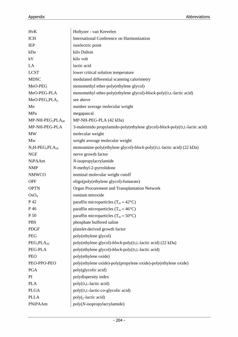
Appendix Abbreviations
- 204 -
HvK Hoftyzer - van Krevelen
ICH International Conference on Harmonization
IEP isoelectric point
kDa kilo Dalton
kV kilo volt
LA lactic acid
LCST lower critical solution temperature
MDSC modulated differential scanning calorimetry
MeO-PEG monomethyl ether-poly(ethylene glycol)
MeO-PEG-PLA monomethyl ether-poly(ethylene glycol)-block-poly(D,L-lactic acid)
MeO-PEGxPLAy see above
Mn number average molecular weight
MPa megapascal
MP-NH-PEG2PLA40 MP-NH-PEG-PLA (42 kDa)
MP-NH-PEG-PLA 3-maleimido propylamido-poly(ethylene glycol)-block-poly(D,L-lactic acid)
MW molecular weight
Mw weight average molecular weight
N2H-PEG2PLA20 monoamine-poly(ethylene glycol)-block-poly(D,L-lactic acid) (22 kDa)
NGF nerve growth factor
NiPAAm N-isopropylacrylamide
NMP N-methyl-2-pyrrolidone
NMWCO nominal molecular weight cutoff
OPF oligo(poly(ethylene glycol)-fumarate)
OPTN Organ Procurement and Transplantation Network
OsO4 osmium tetroxide
P 42 paraffin microparticles (Tm ≈ 42°C)
P 46 paraffin microparticles (Tm ≈ 46°C)
P 50 paraffin microparticles (Tm ≈ 50°C)
PBS phosphate buffered saline
PDGF platelet-derived growth factor
PEG poly(ethylene glycol)
PEG2PLA20 poly(ethylene glycol)-block-poly(D,L-lactic acid) (22 kDa)
PEG-PLA poly(ethylene glycol)-block-poly(D,L-lactic acid)
PEO poly(ethylene oxide)
PEO-PPO-PEO poly(ethylene oxide)-poly(propylene oxide)-poly(ethylene oxide)
PGA poly(glycolic acid)
PI polydispersity index
PLA poly(D,L-lactic acid)
PLGA poly(D,L-lactic-co-glycolic acid)
PLLA poly(L-lactic acid)
PNiPAAm poly(N-isopropylacrylamide)
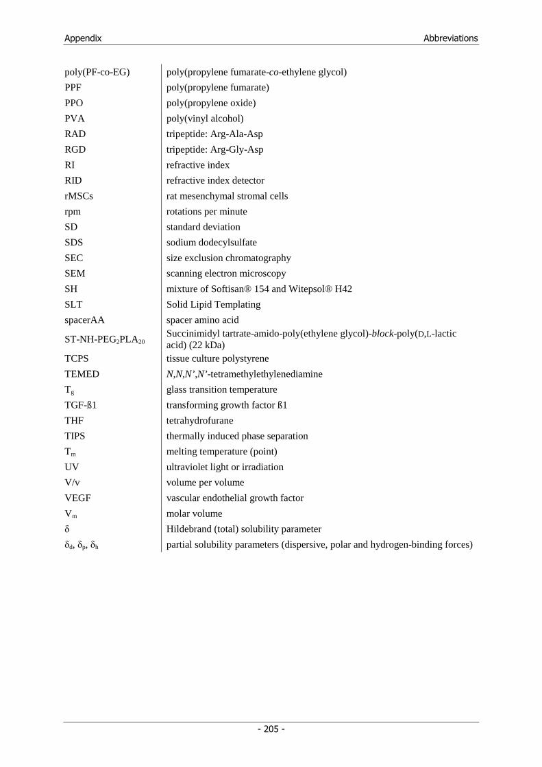
Appendix Abbreviations
- 205 -
poly(PF-co-EG) poly(propylene fumarate-co-ethylene glycol)
PPF poly(propylene fumarate)
PPO poly(propylene oxide)
PVA poly(vinyl alcohol)
RAD tripeptide: Arg-Ala-Asp
RGD tripeptide: Arg-Gly-Asp
RI refractive index
RID refractive index detector
rMSCs rat mesenchymal stromal cells
rpm rotations per minute
SD standard deviation
SDS sodium dodecylsulfate
SEC size exclusion chromatography
SEM scanning electron microscopy
SH mixture of Softisan® 154 and Witepsol® H42
SLT Solid Lipid Templating
spacerAA spacer amino acid
ST-NH-PEG2PLA20 Succinimidyl tartrate-amido-poly(ethylene glycol)-block-poly(D,L-lactic acid) (22 kDa)
TCPS tissue culture polystyrene
TEMED N,N,N’,N’-tetramethylethylenediamine
Tg glass transition temperature
TGF-ß1 transforming growth factor ß1
THF tetrahydrofurane
TIPS thermally induced phase separation
Tm melting temperature (point)
UV ultraviolet light or irradiation
V/v volume per volume
VEGF vascular endothelial growth factor
Vm molar volume
δ Hildebrand (total) solubility parameter
δd, δp, δh partial solubility parameters (dispersive, polar and hydrogen-binding forces)
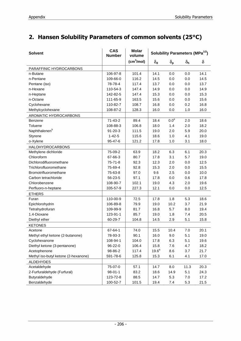
Appendix Solubility Parameters
- 206 -
2. Hansen Solubility Parameters of common solvents (25°C)
Solvent CAS Number
Molar volume Solubility Parameters (MPa1/2)
(cm3/mol) δd δp δh δ PARAFFINIC HYDROCARBONS n-Butane 106-97-8 101.4 14.1 0.0 0.0 14.1 n-Pentane 109-66-0 116.2 14.5 0.0 0.0 14.5 Pentane (iso) 78-78-4 117.4 13.7 0.0 0.0 13.7 n-Hexane 110-54-3 147.4 14.9 0.0 0.0 14.9 n-Heptane 142-82-5 147.4 15.3 0.0 0.0 15.3 n-Octane 111-65-9 163.5 15.6 0.0 0.0 15.6 Cyclohexane 110-82-7 108.7 16.8 0.0 0.2 16.8 Methylcyclohexane 108-87-2 128.3 16.0 0.0 1.0 16.0
AROMATIC HYDROCARBONS Benzene 71-43-2 89.4 18.4 0.0a 2.0 18.6 Toluene 108-88-3 106.8 18.0 1.4 2.0 18.2 Naphthalenenb 91-20-3 111.5 19.0 2.0 5.9 20.0 Styrene 1-42-5 115.6 18.6 1.0 4.1 19.0 o-Xylene 95-47-6 121.2 17.8 1.0 3.1 18.0
HALOHYDROCARBONS Methylene dichloride 75-09-2 63.9 18.2 6.3 6.1 20.3 Chloroform 67-66-3 80.7 17.8 3.1 5.7 19.0 Dichlorodifluoromethane 75-71-8 92.3 12.3 2.0 0.0 12.5 Trichlorofluoromethane 75-69-4 92.8 15.3 2.0 0.0 15.5 Bromotrifluoromethane 75-63-8 97.0 9.6 2.5 0.0 10.0 Carbon tetrachloride 56-23-5 97.1 17.8 0.0 0.6 17.8 Chlorobenzene 108-90-7 102.1 19.0 4.3 2.0 19.6 Perfluoro-n-heptane 335-57-9 227.3 12.1 0.0 0.0 12.5
ETHERS Furan 110-00-9 72.5 17.8 1.8 5.3 18.6 Epichlorohydrin 106-89-8 79.9 19.0 10.2 3.7 21.9 Tetrahydrofuran 109-99-9 81.7 16.8 5.7 8.0 19.4 1.4-Dioxane 123-91-1 85.7 19.0 1.8 7.4 20.5 Diethyl ether 60-29-7 104.8 14.5 2.9 5.1 15.8
KETONES Acetone 67-64-1 74.0 15.5 10.4 7.0 20.1 Methyl ethyl ketone (2-butanone) 78-93-3 90.1 16.0 9.0 5.1 19.0 Cyclohexanone 108-94-1 104.0 17.8 6.3 5.1 19.6 Diethyl ketone (3-pentanone) 96-22-0 106.4 15.8 7.6 4.7 18.2 Acetophenone 98-86-2 117.4 19.6a 8.6 3.7 21.7 Methyl iso-butyl ketone (2-hexanone) 591-78-6 125.8 15.3 6.1 4.1 17.0
ALDEHYDES Acetaldehyde 75-07-0 57.1 14.7 8.0 11.3 20.3 2-Furfuraldehyde (Furfural) 98-01-1 83.2 18.6 14.9 5.1 24.3 Butyraldehyde 123-72-8 88.5 14.7 5.3 7.0 17.2 Benzaldehyde 100-52-7 101.5 19.4 7.4 5.3 21.5
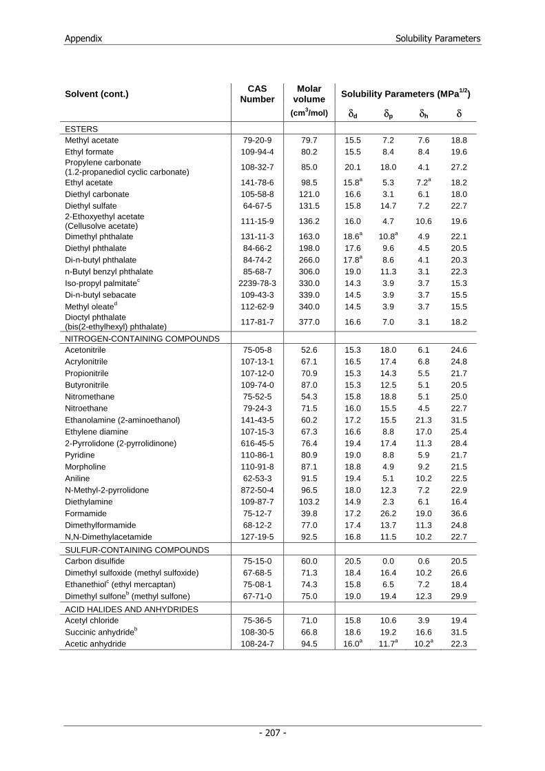
Appendix Solubility Parameters
- 207 -
Solvent (cont.) CAS Number
Molar volume Solubility Parameters (MPa1/2)
(cm3/mol) δd δp δh δ ESTERS Methyl acetate 79-20-9 79.7 15.5 7.2 7.6 18.8 Ethyl formate 109-94-4 80.2 15.5 8.4 8.4 19.6 Propylene carbonate (1.2-propanediol cyclic carbonate)
108-32-7 85.0 20.1 18.0 4.1 27.2
Ethyl acetate 141-78-6 98.5 15.8a 5.3 7.2a 18.2 Diethyl carbonate 105-58-8 121.0 16.6 3.1 6.1 18.0 Diethyl sulfate 64-67-5 131.5 15.8 14.7 7.2 22.7 2-Ethoxyethyl acetate (Cellusolve acetate) 111-15-9 136.2 16.0 4.7 10.6 19.6
Dimethyl phthalate 131-11-3 163.0 18.6a 10.8a 4.9 22.1 Diethyl phthalate 84-66-2 198.0 17.6 9.6 4.5 20.5 Di-n-butyl phthalate 84-74-2 266.0 17.8a 8.6 4.1 20.3 n-Butyl benzyl phthalate 85-68-7 306.0 19.0 11.3 3.1 22.3 Iso-propyl palmitatec 2239-78-3 330.0 14.3 3.9 3.7 15.3 Di-n-butyl sebacate 109-43-3 339.0 14.5 3.9 3.7 15.5 Methyl oleated 112-62-9 340.0 14.5 3.9 3.7 15.5 Dioctyl phthalate (bis(2-ethylhexyl) phthalate) 117-81-7 377.0 16.6 7.0 3.1 18.2
NITROGEN-CONTAINING COMPOUNDS Acetonitrile 75-05-8 52.6 15.3 18.0 6.1 24.6 Acrylonitrile 107-13-1 67.1 16.5 17.4 6.8 24.8 Propionitrile 107-12-0 70.9 15.3 14.3 5.5 21.7 Butyronitrile 109-74-0 87.0 15.3 12.5 5.1 20.5 Nitromethane 75-52-5 54.3 15.8 18.8 5.1 25.0 Nitroethane 79-24-3 71.5 16.0 15.5 4.5 22.7 Ethanolamine (2-aminoethanol) 141-43-5 60.2 17.2 15.5 21.3 31.5 Ethylene diamine 107-15-3 67.3 16.6 8.8 17.0 25.4 2-Pyrrolidone (2-pyrrolidinone) 616-45-5 76.4 19.4 17.4 11.3 28.4 Pyridine 110-86-1 80.9 19.0 8.8 5.9 21.7 Morpholine 110-91-8 87.1 18.8 4.9 9.2 21.5 Aniline 62-53-3 91.5 19.4 5.1 10.2 22.5 N-Methyl-2-pyrrolidone 872-50-4 96.5 18.0 12.3 7.2 22.9 Diethylamine 109-87-7 103.2 14.9 2.3 6.1 16.4 Formamide 75-12-7 39.8 17.2 26.2 19.0 36.6 Dimethylformamide 68-12-2 77.0 17.4 13.7 11.3 24.8 N,N-Dimethylacetamide 127-19-5 92.5 16.8 11.5 10.2 22.7
SULFUR-CONTAINING COMPOUNDS Carbon disulfide 75-15-0 60.0 20.5 0.0 0.6 20.5 Dimethyl sulfoxide (methyl sulfoxide) 67-68-5 71.3 18.4 16.4 10.2 26.6 Ethanethiolc (ethyl mercaptan) 75-08-1 74.3 15.8 6.5 7.2 18.4 Dimethyl sulfoneb (methyl sulfone) 67-71-0 75.0 19.0 19.4 12.3 29.9
ACID HALIDES AND ANHYDRIDES Acetyl chloride 75-36-5 71.0 15.8 10.6 3.9 19.4 Succinic anhydrideb 108-30-5 66.8 18.6 19.2 16.6 31.5 Acetic anhydride 108-24-7 94.5 16.0a 11.7a 10.2a 22.3
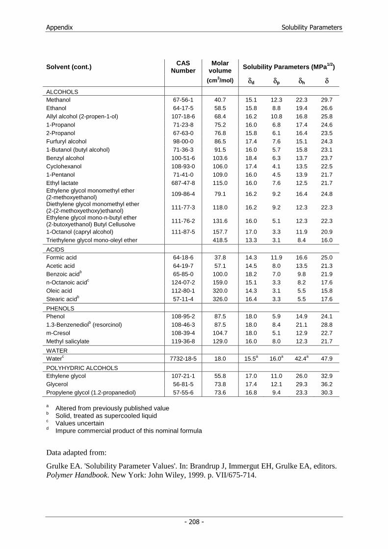
Appendix Solubility Parameters
- 208 -
Solvent (cont.) CAS Number
Molar volume Solubility Parameters (MPa1/2)
(cm3/mol) δd δp δh δ ALCOHOLS Methanol 67-56-1 40.7 15.1 12.3 22.3 29.7 Ethanol 64-17-5 58.5 15.8 8.8 19.4 26.6 Allyl alcohol (2-propen-1-ol) 107-18-6 68.4 16.2 10.8 16.8 25.8 1-Propanol 71-23-8 75.2 16.0 6.8 17.4 24.6 2-Propanol 67-63-0 76.8 15.8 6.1 16.4 23.5 Furfuryl alcohol 98-00-0 86.5 17.4 7.6 15.1 24.3 1-Butanol (butyl alcohol) 71-36-3 91.5 16.0 5.7 15.8 23.1 Benzyl alcohol 100-51-6 103.6 18.4 6.3 13.7 23.7 Cyclohexanol 108-93-0 106.0 17.4 4.1 13.5 22.5 1-Pentanol 71-41-0 109.0 16.0 4.5 13.9 21.7 Ethyl lactate 687-47-8 115.0 16.0 7.6 12.5 21.7 Ethylene glycol monomethyl ether (2-methoxyethanol) 109-86-4 79.1 16.2 9.2 16.4 24.8
Diethylene glycol monomethyl ether (2-(2-methoxyethoxy)ethanol) 111-77-3 118.0 16.2 9.2 12.3 22.3
Ethylene glycol mono-n-butyl ether (2-butoxyethanol) Butyl Cellusolve 111-76-2 131.6 16.0 5.1 12.3 22.3
1-Octanol (capryl alcohol) 111-87-5 157.7 17.0 3.3 11.9 20.9 Triethylene glycol mono-oleyl ether 418.5 13.3 3.1 8.4 16.0
ACIDS Formic acid 64-18-6 37.8 14.3 11.9 16.6 25.0 Acetic acid 64-19-7 57.1 14.5 8.0 13.5 21.3 Benzoic acidb 65-85-0 100.0 18.2 7.0 9.8 21.9 n-Octanoic acidc 124-07-2 159.0 15.1 3.3 8.2 17.6 Oleic acid 112-80-1 320.0 14.3 3.1 5.5 15.8 Stearic acidb 57-11-4 326.0 16.4 3.3 5.5 17.6
PHENOLS Phenol 108-95-2 87.5 18.0 5.9 14.9 24.1 1.3-Benzenediolb (resorcinol) 108-46-3 87.5 18.0 8.4 21.1 28.8 m-Cresol 108-39-4 104.7 18.0 5.1 12.9 22.7 Methyl salicylate 119-36-8 129.0 16.0 8.0 12.3 21.7
WATER Waterc 7732-18-5 18.0 15.5a 16.0a 42.4a 47.9
POLYHYDRIC ALCOHOLS Ethylene glycol 107-21-1 55.8 17.0 11.0 26.0 32.9 Glycerol 56-81-5 73.8 17.4 12.1 29.3 36.2 Propylene glycol (1.2-propanediol) 57-55-6 73.6 16.8 9.4 23.3 30.3
a Altered from previously published value b Solid, treated as supercooled liquid c Values uncertain d Impure commercial product of this nominal formula
Data adapted from:
Grulke EA. 'Solubility Parameter Values'. In: Brandrup J, Immergut EH, Grulke EA, editors. Polymer Handbook. New York: John Wiley, 1999. p. VII/675-714.
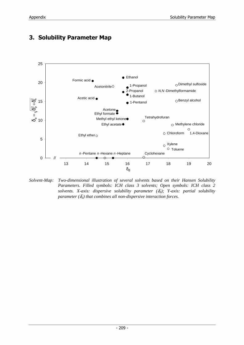
Appendix Solubility Parameter Map
- 209 -
3. Solubility Parameter Map
0
5
10
15
20
25
12 13 14 15 16 17 18 19 20
Tetrahydrofuran
Benzyl alcohol
Formic acid
Acetic acid
Ethyl ether
n -Pentane n -Heptane
AcetonitrileDimethyl sulfoxide
Ethyl formateAcetone
Ethyl acetate
Methyl ethyl ketone
N,N -Dimethylformamide2-Propanol
Ethanol
1-Pentanol
1-Butanol
1-Propanol
Chloroform
n -Hexane Cyclohexane
Methylene chloride
1,4-Dioxane
Xylene
Toluene
//
dδ
2 h2 p
aδ
δδ
+=
Solvent-Map: Two-dimensional illustration of several solvents based on their Hansen Solubility Parameters. Filled symbols: ICH class 3 solvents; Open symbols: ICH class 2 solvents. X-axis: dispersive solubility parameter (δd); Y-axis: partial solubility parameter (δa) that combines all non-dispersive interaction forces.
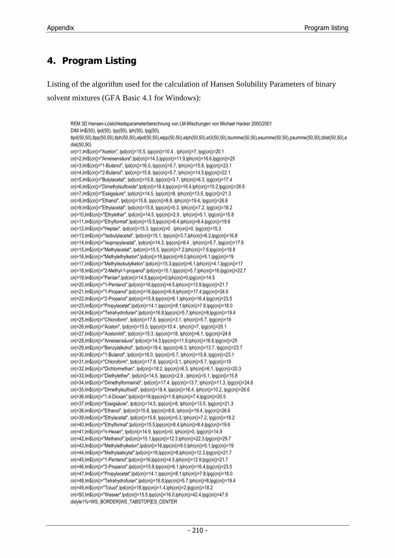
Appendix Program listing
- 210 -
4. Program Listing
Listing of the algorithm used for the calculation of Hansen Solubility Parameters of binary
solvent mixtures (GFA Basic 4.1 for Windows):
REM 3D Hansen-Löslichkeitsparameterberechnung von LM-Mischungen von Michael Hacker 2000/2001 DIM lm$(50), lpd(50), lpp(50), lph(50), lpg(50), tlpd(50,50),tlpp(50,50),tlph(50,50),elpd(50,50),elpp(50,50),elph(50,50),et3(50,50),tsumme(50,50),esumme(50,50),psumme(50,50),tdist(50,50),edist(50,50) cn|=1,lm$(cn|)="Aceton", lpd(cn|)=15.5, lpp(cn|)=10.4 , lph(cn|)=7, lpg(cn|)=20.1 cn|=2,lm$(cn|)="Ameisensäure",lpd(cn|)=14.3,lpp(cn|)=11.9,lph(cn|)=16.6,lpg(cn|)=25 cn|=3,lm$(cn|)="1-Butanol", lpd(cn|)=16.0, lpp(cn|)=5.7, lph(cn|)=15.8, lpg(cn|)=23.1 cn|=4,lm$(cn|)="2-Butanol", lpd(cn|)=15.8, lpp(cn|)=5.7, lph(cn|)=14.5,lpg(cn|)=22.1 cn|=5,lm$(cn|)="Butylacetat", lpd(cn|)=15.8, lpp(cn|)=3.7, lph(cn|)=6.3, lpg(cn|)=17.4 cn|=6,lm$(cn|)="Dimethylsulfoxide",lpd(cn|)=18.4,lpp(cn|)=16.4,lph(cn|)=10.2,lpg(cn|)=26.6 cn|=7,lm$(cn|)="Essigsäure", lpd(cn|)=14.5, lpp(cn|)=8, lph(cn|)=13.5, lpg(cn|)=21.3 cn|=8,lm$(cn|)="Ethanol", lpd(cn|)=15.8, lpp(cn|)=8.8, lph(cn|)=19.4, lpg(cn|)=26.6 cn|=9,lm$(cn|)="Ethylacetat", lpd(cn|)=15.8, lpp(cn|)=5.3, lph(cn|)=7.2, lpg(cn|)=18.2 cn|=10,lm$(cn|)="Ethylether", lpd(cn|)=14.5, lpp(cn|)=2.9 , lph(cn|)=5.1, lpg(cn|)=15.8 cn|=11,lm$(cn|)="Ethylformat",lpd(cn|)=15.5,lpp(cn|)=8.4,lph(cn|)=8.4,lpg(cn|)=19.6 cn|=12,lm$(cn|)="Heptan", lpd(cn|)=15.3, lpp(cn|)=0 , lph(cn|)=0, lpg(cn|)=15.3 cn|=13,lm$(cn|)="Isobutylacetat", lpd(cn|)=15.1, lpp(cn|)=3.7,lph(cn|)=6.3,lpg(cn|)=16.8 cn|=14,lm$(cn|)="Isopropylacetat", lpd(cn|)=14.3, lpp(cn|)=8.4 , lph(cn|)=5.7, lpg(cn|)=17.6 cn|=15,lm$(cn|)="Methylacetat", lpd(cn|)=15.5, lpp(cn|)=7.2,lph(cn|)=7.6,lpg(cn|)=18.8 cn|=16,lm$(cn|)="Methylethylketon",lpd(cn|)=16,lpp(cn|)=9.0,lph(cn|)=5.1,lpg(cn|)=19 cn|=17,lm$(cn|)="Methylisobutylketon",lpd(cn|)=15.3,lpp(cn|)=6.1,lph(cn|)=4.1,lpg(cn|)=17 cn|=18,lm$(cn|)="2-Methyl-1-propanol",lpd(cn|)=15.1,lpp(cn|)=5.7,lph(cn|)=16,lpg(cn|)=22.7 cn|=19,lm$(cn|)="Pentan",lpd(cn|)=14.5,lpp(cn|)=0,lph(cn|)=0,lpg(cn|)=14.5 cn|=20,lm$(cn|)="1-Pentanol",lpd(cn|)=16,lpp(cn|)=4.5,lph(cn|)=13.9,lpg(cn|)=21.7 cn|=21,lm$(cn|)="1-Propanol",lpd(cn|)=16,lpp(cn|)=6.8,lph(cn|)=17.4,lpg(cn|)=24.6 cn|=22,lm$(cn|)="2-Propanol",lpd(cn|)=15.8,lpp(cn|)=6.1,lph(cn|)=16.4,lpg(cn|)=23.5 cn|=23,lm$(cn|)="Propylacetat",lpd(cn|)=14.1,lpp(cn|)=8.1,lph(cn|)=7.8,lpg(cn|)=18.0 cn|=24,lm$(cn|)="Tetrahydrofuran",lpd(cn|)=16.8,lpp(cn|)=5.7,lph(cn|)=8,lpg(cn|)=19.4 cn|=25,lm$(cn|)="Chloroform", lpd(cn|)=17.8, lpp(cn|)=3.1, lph(cn|)=5.7, lpg(cn|)=19 cn|=26,lm$(cn|)="Aceton", lpd(cn|)=15.5, lpp(cn|)=10.4 , lph(cn|)=7, lpg(cn|)=20.1 cn|=27,lm$(cn|)="Acetonitril", lpd(cn|)=15.3, lpp(cn|)=18, lph(cn|)=6.1, lpg(cn|)=24.6 cn|=28,lm$(cn|)="Ameisensäure",lpd(cn|)=14.3,lpp(cn|)=11.9,lph(cn|)=16.6,lpg(cn|)=25 cn|=29,lm$(cn|)="Benzylalkohol", lpd(cn|)=18.4, lpp(cn|)=6.3, lph(cn|)=13.7, lpg(cn|)=23.7 cn|=30,lm$(cn|)="1-Butanol", lpd(cn|)=16.0, lpp(cn|)=5.7, lph(cn|)=15.8, lpg(cn|)=23.1 cn|=31,lm$(cn|)="Chloroform", lpd(cn|)=17.8, lpp(cn|)=3.1, lph(cn|)=5.7, lpg(cn|)=19 cn|=32,lm$(cn|)="Dichlormethan", lpd(cn|)=18.2, lpp(cn|)=6.3, lph(cn|)=6.1, lpg(cn|)=20.3 cn|=33,lm$(cn|)="Diethylether", lpd(cn|)=14.5, lpp(cn|)=2.9 , lph(cn|)=5.1, lpg(cn|)=15.8 cn|=34,lm$(cn|)="Dimethylformamid", lpd(cn|)=17.4, lpp(cn|)=13.7, lph(cn|)=11.3, lpg(cn|)=24.8 cn|=35,lm$(cn|)="Dimethylsulfoxid", lpd(cn|)=18.4, lpp(cn|)=16.4, lph(cn|)=10.2, lpg(cn|)=26.6 cn|=36,lm$(cn|)="1,4-Dioxan",lpd(cn|)=19,lpp(cn|)=1.8,lph(cn|)=7.4,lpg(cn|)=20.5 cn|=37,lm$(cn|)="Essigsäure", lpd(cn|)=14.5, lpp(cn|)=8, lph(cn|)=13.5, lpg(cn|)=21.3 cn|=38,lm$(cn|)="Ethanol", lpd(cn|)=15.8, lpp(cn|)=8.8, lph(cn|)=19.4, lpg(cn|)=26.6 cn|=39,lm$(cn|)="Ethylacetat", lpd(cn|)=15.8, lpp(cn|)=5.3, lph(cn|)=7.2, lpg(cn|)=18.2 cn|=40,lm$(cn|)="Ethylformat",lpd(cn|)=15.5,lpp(cn|)=8.4,lph(cn|)=8.4,lpg(cn|)=19.6 cn|=41,lm$(cn|)="n-Hexan", lpd(cn|)=14.9, lpp(cn|)=0, lph(cn|)=0, lpg(cn|)=14.9 cn|=42,lm$(cn|)="Methanol",lpd(cn|)=15.1,lpp(cn|)=12.3,lph(cn|)=22.3,lpg(cn|)=29.7 cn|=43,lm$(cn|)="Methylethylketon",lpd(cn|)=16,lpp(cn|)=9.0,lph(cn|)=5.1,lpg(cn|)=19 cn|=44,lm$(cn|)="Methylsalicylat",lpd(cn|)=16,lpp(cn|)=8,lph(cn|)=12.3,lpg(cn|)=21.7 cn|=45,lm$(cn|)="1-Pentanol",lpd(cn|)=16,lpp(cn|)=4.5,lph(cn|)=13.9,lpg(cn|)=21.7 cn|=46,lm$(cn|)="2-Propanol",lpd(cn|)=15.8,lpp(cn|)=6.1,lph(cn|)=16.4,lpg(cn|)=23.5 cn|=47,lm$(cn|)="Propylacetat",lpd(cn|)=14.1,lpp(cn|)=8.1,lph(cn|)=7.8,lpg(cn|)=18.0 cn|=48,lm$(cn|)="Tetrahydrofuran",lpd(cn|)=16.8,lpp(cn|)=5.7,lph(cn|)=8,lpg(cn|)=19.4 cn|=49,lm$(cn|)="Toluol",lpd(cn|)=18,lpp(cn|)=1.4,lph(cn|)=2,lpg(cn|)=18.2 cn|=50,lm$(cn|)="Wasser",lpd(cn|)=15.5,lpp(cn|)=16.0,lph(cn|)=42.4,lpg(cn|)=47.9 dstyle1%=WS_BORDER|WS_TABSTOP|ES_CENTER
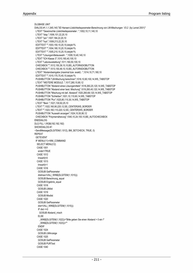
Appendix Program listing
- 211 -
DLGBASE UNIT DIALOG #1,1,1,345,140,"3D Hansen-Löslichkeitsparameter-Berechnung von LM-Mischungen V3.2 (by Lerxst 2001)" LTEXT "Gewünschte Löslichkeitsparameter : ",1002,10,11,140,10 LTEXT "disp.",1006,151,22,20,10 LTEXT "pol.",1007,184,22,20,10 LTEXT "hyd.",1008,213,22,20,10 EDITTEXT "",1003,150,10,20,10,dstyle1% EDITTEXT "",1004,180,10,20,10,dstyle1% EDITTEXT "",1005,210,10,20,10,dstyle1% LTEXT "Lösungsmittelauswahl : ",1009,10,40,140,10 LTEXT "ICH Klasse 3",1010,160,40,100,10 LTEXT "Laborausstattung",1011,160,50,100,10 CHECKBOX "",1012,150,39,10,10,BS_AUTORADIOBUTTON CHECKBOX "",1013,150,49,10,10,BS_AUTORADIOBUTTON LTEXT "Abstandseingabe (maximal bzw. exakt) : ",1014,10,71,160,10 EDITTEXT "",1015,170,70,40,10,dstyle1% PUSHBUTTON "LM-Mischung berechnen",1016,10,90,100,14,WS_TABSTOP LTEXT "WEITERE MODULE :",1017,260,10,80,12 PUSHBUTTON "Abstand eines Lösungsmittels",1018,260,25,120,14,WS_TABSTOP PUSHBUTTON "Abstand einer best. Mischung",1019,260,45,120,14,WS_TABSTOP PUSHBUTTON "Mischung mit def. Abstand",1020,260,68,120,14,WS_TABSTOP PUSHBUTTON "Schließen",1001,10,110,60,14,WS_TABSTOP PUSHBUTTON "Pur",1025,80,110,30,14,WS_TABSTOP LTEXT "Best :",1021,130,92,25,10 LTEXT "",1022,160,90,220,12,SS_CENTER|WS_BORDER LTEXT "",1023,160,110,220,12,SS_CENTER|WS_BORDER PUSHBUTTON "Auswahl anzeigen",1024,10,50,90,12 CHECKBOX "Polymernäherung",1040,10,24,100,10,BS_AUTOCHECKBOX ENDDIALOG DLG FILL 1,RGB(192,192,192) SHOWDIALOG #1 ~SendMessage(DLGITEM(1,1012), BM_SETCHECK, TRUE, 0) REPEAT GETEVENT IF MENU(11)=WM_COMMAND SELECT MENU(12) CASE 1001 ende!=TRUE CASE 1012 lmwahl|=0 CASE 1013 lmwahl|=1 CASE 1016 GOSUB GetParameter distmax=VAL(_WIN$(DLGITEM(1,1015))) GOSUB Berechnung_equal GOSUB Ergebnis_equal CASE 1018 GOSUB LMdist CASE 1019 GOSUB Mixdist CASE 1020 GOSUB GetParameter dist=VAL(_WIN$(DLGITEM(1,1015))) IF dist <>0 GOSUB Abstand_misch ELSE _WIN$(DLGITEM(1,1022))="Bitte geben Sie einen Abstand > 0 ein !" _WIN$(DLGITEM(1,1023))="" ENDIF CASE 1024 GOSUB LMAnzeige CASE 1025 GOSUB GetParameter GOSUB PURTest CASE 1040
Appendix Program listing
- 212 -
IF polyn|=0 polyn|=1 ELSE polyn|=0 ENDIF ENDSELECT ENDIF UNTIL ende! CLOSEDIALOG #1 > PROCEDURE GetParameter wlpd=VAL(_WIN$(DLGITEM(1,1003))) wlpp=VAL(_WIN$(DLGITEM(1,1004))) wlph=VAL(_WIN$(DLGITEM(1,1005))) RETURN > PROCEDURE LMAnzeige OPENW #1,2,300,690,300,0 TITLEW #1,"Lösungsmittelauswahl" zei|=0 FOR lmp|=1+(lmwahl|*25) TO 24+(lmwahl|*1)+(lmwahl|*25) STEP 2 INC zei| TEXT 10,zei|*20,lmp|-(lmwahl|*25) TEXT 40,zei|*20,lm$(lmp|) TEXT 200,zei|*20,lpd(lmp|) TEXT 240,zei|*20,lpp(lmp|) TEXT 280,zei|*20,lph(lmp|) IF lmp|<>50 TEXT 370,zei|*20,(lmp|+1)-(lmwahl|*25) TEXT 400,zei|*20,lm$(lmp|+1) TEXT 550,zei|*20,lpd(lmp|+1) TEXT 590,zei|*20,lpp(lmp|+1) TEXT 630,zei|*20,lph(lmp|+1) ENDIF NEXT lmp| COLOR 249 PRINT " Zum Fortsetzen bitte Taste drücken" KEYGET pause CLOSEW #1 RETURN > PROCEDURE LMdist LOCAL subende!,res$ DLGBASE UNIT DIALOG #2,350,1,160,290,"Abstandsberechnung" zei|=0 FOR lmp|=1+(lmwahl|*25) TO 24+(lmwahl|*1)+(lmwahl|*25) STEP 2 INC zei| CHECKBOX lm$(lmp|),(2000+lmp|),5,((zei|-1)*20),90,20,BS_AUTORADIOBUTTON IF lmp|<>50 CHECKBOX lm$(lmp|+1),(2000+lmp|+1),95,((zei|-1)*20),90,20,BS_AUTORADIOBUTTON ENDIF NEXT lmp| PUSHBUTTON "Distanz berechnen",2051,5,260,80,14,WS_TABSTOP PUSHBUTTON "Schließen",2052,95,260,60,14,WS_TABSTOP ENDDIALOG SHOWDIALOG #2 DLG FILL 2,RGB(192,192,192) REPEAT GETEVENT IF MENU(11)=WM_COMMAND IF 2000<MENU(12) AND MENU(12)<2051 THEN slm|=MENU(12)-2000 SELECT MENU(12) CASE 2051 GOSUB GetParameter tsumme=SQR((polyn|*3+1)*(wlpd-lpd(slm|))^2+(wlpp-lpp(slm|))^2+(wlph-lph(slm|))^2) res$="Abstand zu "+lm$(slm|)+" : "+STR$(ROUND(tsumme,1))+" ("+STR$(ROUND((tsumme)^2,1))+")"

Appendix Program listing
- 213 -
_WIN$(DLGITEM(1,1022))="" _WIN$(DLGITEM(1,1023))=res$ CASE 2052 subende!=TRUE CASE 1040 IF polyn|=0 polyn|=1 ELSE polyn|=0 ENDIF ENDSELECT ENDIF UNTIL subende! CLOSEDIALOG #2 RETURN > PROCEDURE Berechnung_equal t1|=0,t2|=0 FOR t1|=1+(lmwahl|*25) TO 24+(lmwahl|*1)+(lmwahl|*25) FOR t2|=t1| TO 24+(lmwahl|*1)+(lmwahl|*25) IF t1|<>t2| FOR t3=0 TO 1 STEP 0.01 tlpd(t1|,t2|)=t3*lpd(t1|)+(1-t3)*lpd(t2|) tlpp(t1|,t2|)=t3*lpp(t1|)+(1-t3)*lpp(t2|) tlph(t1|,t2|)=t3*lph(t1|)+(1-t3)*lph(t2|) tsumme(t1|,t2|)=SQR((polyn|*3+1)*(wlpd-tlpd(t1|,t2|))^2+(wlpp-tlpp(t1|,t2|))^2+(wlph-tlph(t1|,t2|))^2) IF t3=0 THEN et3(t1|,t2|)=ROUND(t3,2) esumme(t1|,t2|)=tsumme(t1|,t2|) ENDIF IF tsumme(t1|,t2|)<esumme(t1|,t2|) et3(t1|,t2|)=ROUND(t3,2) esumme(t1|,t2|)=tsumme(t1|,t2|) ENDIF NEXT t3 ENDIF NEXT t2| NEXT t1| RETURN > PROCEDURE Ergebnis_equal OPENW #2,2,300,690,400,0 TITLEW #2,"Lösungsmittelaustausch" LOCAL dcount|,res1$,res2$ dcount|=0 t1|=0,t2|=0 COLOR 0 IF lmwahl|=0 THEN best=esumme(1,2) ELSE IF lmwahl|=1 best=esumme(26,27) ENDIF FOR t1|=1+(lmwahl|*25) TO 24+(lmwahl|*1)+(lmwahl|*25) FOR t2|=t1| TO 24+(lmwahl|*1)+(lmwahl|*25) IF t1|<>t2| THEN elpd(t1|,t2|)=ROUND(et3(t1|,t2|)*lpd(t1|)+(1-et3(t1|,t2|))*lpd(t2|),1) elpp(t1|,t2|)=ROUND(et3(t1|,t2|)*lpp(t1|)+(1-et3(t1|,t2|))*lpp(t2|),1) elph(t1|,t2|)=ROUND(et3(t1|,t2|)*lph(t1|)+(1-et3(t1|,t2|))*lph(t2|),1) IF esumme(t1|,t2|)<best THEN best=esumme(t1|,t2|) bestt1|=t1| bestt2|=t2| ENDIF IF esumme(t1|,t2|)<=distmax AND ROUND(et3(t1|,t2|),2)<>0 AND ROUND(et3(t1|,t2|),2)<>1 THEN INC dcount| PRINT " Mix: ";lm$(t1|);" und ";lm$(t2|);" - ratio: ";et3(t1|,t2|);" / ";ROUND(1-et3(t1|,t2|),2);" - value: ";elpd(t1|,t2|);" ";elpp(t1|,t2|);" ";elph(t1|,t2|);" dist.: ";ROUND(esumme(t1|,t2|),1)
Appendix Program listing
- 214 -
IF INT(dcount|/20)=dcount|/20 PRINT PRINT "Bitte Taste für weitere Ergebnisse drücken" REPEAT UNTIL INKEY$<>"" CLS dcount|=0 ENDIF ENDIF ENDIF NEXT t2| NEXT t1| res1$=lm$(bestt1|)+" und "+lm$(bestt2|)+" - "+STR$(et3(bestt1|,bestt2|))+" zu "+STR$(ROUND(1-et3(bestt1|,bestt2|),2)) res2$="Parameter: "+STR$(ROUND(elpd(bestt1|,bestt2|),1))+" "+STR$(ROUND(elpp(bestt1|,bestt2|),1))+" "+STR$(ROUND(elph(bestt1|,bestt2|),1))+" Abstand: "+STR$(ROUND(esumme(bestt1|,bestt2|),1)) _WIN$(DLGITEM(1,1022))=res1$ _WIN$(DLGITEM(1,1023))=res2$ PRINT COLOR 249 PRINT " Ergebnisausgabe beendet - Bitte Taste drücken" KEYGET pause CLOSEW #2 RETURN > PROCEDURE Abstand_misch OPENW #3,2,300,690,400,0 TITLEW #3,"Lösungsmittel in definiertem Abstand" LOCAL dcount|,res1$,res2$ dcount|=0 best=dist*1000 bdist=dist*1000 brdist=dist*1000 t1|=0,t2|=0 FOR t1|=1+(lmwahl|*25) TO 24+(lmwahl|*1)+(lmwahl|*25) FOR t2|=t1| TO 24+(lmwahl|*1)+(lmwahl|*25) IF t1|<>t2| tdist(t1|,t2|)=dist FOR t3=0 TO 1 STEP 0.01 tlpd(t1|,t2|)=t3*lpd(t1|)+(1-t3)*lpd(t2|) tlpp(t1|,t2|)=t3*lpp(t1|)+(1-t3)*lpp(t2|) tlph(t1|,t2|)=t3*lph(t1|)+(1-t3)*lph(t2|) tsumme(t1|,t2|)=SQR((polyn|*3+1)*(wlpd-tlpd(t1|,t2|))^2+(wlpp-tlpp(t1|,t2|))^2+(wlph-tlph(t1|,t2|))^2) IF t3=0 et3(t1|,t2|)=ROUND(t3,2) esumme(t1|,t2|)=tsumme(t1|,t2|) ENDIF IF ABS(tsumme(t1|,t2|)-dist)<tdist(t1|,t2|) tdist(t1|,t2|)=ABS(tsumme(t1|,t2|)-dist) edist(t1|,t2|)=tsumme(t1|,t2|) et3(t1|,t2|)=ROUND(t3,2) esumme(t1|,t2|)=tsumme(t1|,t2|) ENDIF IF ABS(tsumme(t1|,t2|)-dist)<brdist brdist=ABS(tsumme(t1|,t2|)-dist) bdist=tsumme(t1|,t2|) ENDIF NEXT t3 ENDIF NEXT t2| NEXT t1| cabs=dist*1000 FOR t1|=1+(lmwahl|*25) TO 24+(lmwahl|*1)+(lmwahl|*25) FOR t2|=t1| TO 24+(lmwahl|*1)+(lmwahl|*25) IF t1|<>t2| THEN elpd(t1|,t2|)=ROUND(et3(t1|,t2|)*lpd(t1|)+(1-et3(t1|,t2|))*lpd(t2|),1) elpp(t1|,t2|)=ROUND(et3(t1|,t2|)*lpp(t1|)+(1-et3(t1|,t2|))*lpp(t2|),1) elph(t1|,t2|)=ROUND(et3(t1|,t2|)*lph(t1|)+(1-et3(t1|,t2|))*lph(t2|),1)
Appendix Program listing
- 215 -
ENDIF IF ABS(esumme(t1|,t2|)-dist)<cabs THEN cabs=ABS(esumme(t1|,t2|)-dist) cabst1|=t1| cabst2|=t2| ENDIF IF ROUND(esumme(t1|,t2|))=dist THEN INC dcount| PRINT " Mix: ";lm$(t1|);" und ";lm$(t2|);" - ratio: ";et3(t1|,t2|);" / ";ROUND(1-et3(t1|,t2|),2);" - value: ";elpd(t1|,t2|);" ";elpp(t1|,t2|);" ";elph(t1|,t2|);" dist.: ";ROUND(esumme(t1|,t2|),1) IF INT(dcount|/20)=dcount|/20 PRINT PRINT " Bitte Taste für weitere Ergebnisse drücken" REPEAT UNTIL INKEY$<>"" CLS dcount|=0 ENDIF ENDIF NEXT t2| NEXT t1| IF cabst1|<>1 OR cabst2|<>1 AND cabst1|<>26 OR cabst2|<>26 AND ROUND(dist)=ROUND(esumme(cabst1|,cabst2|)) res1$=lm$(cabst1|)+" und "+lm$(cabst2|)+" - "+STR$(et3(cabst1|,cabst2|))+" zu "+STR$(ROUND(1-et3(cabst1|,cabst2|),2)) res2$="Parameter: "+STR$(ROUND(elpd(cabst1|,cabst2|),1))+" "+STR$(ROUND(elpp(cabst1|,cabst2|),1))+" "+STR$(ROUND(elph(cabst1|,cabst2|),1))+" Abstand: "+STR$(ROUND(esumme(cabst1|,cabst2|),1)) _WIN$(DLGITEM(1,1022))=res1$ _WIN$(DLGITEM(1,1023))=res2$ ELSE res1$="" res2$="" _WIN$(DLGITEM(1,1022))=res1$ _WIN$(DLGITEM(1,1023))=res2$ COLOR 249 PRINT PRINT " Nächster erreichbarer Abstand: ";ROUND(bdist,1) ENDIF COLOR 249 PRINT PRINT " Ergebnisausgabe beendet - Bitte Taste drücken" KEYGET pause CLOSEW #3 RETURN > PROCEDURE PURTest best=100000 t1|=0 FOR t1|=1+(lmwahl|*25) TO 24+(lmwahl|*1)+(lmwahl|*25) tsumme=SQR((polyn|*3+1)*(wlpd-lpd(t1|))^2+(wlpp-lpp(t1|))^2+(wlph-lph(t1|))^2) IF tsumme<best best=tsumme et1|=t1| esumme=tsumme ENDIF NEXT t1| res1$=lm$(et1|) res2$="Parameter: "+STR$(lpd(et1|))+" "+STR$(lpp(et1|))+" "+STR$(lph(et1|))+" Abstand: "+STR$(ROUND(esumme,1))+" ("+STR$(ROUND((esumme)^2,1))+")" _WIN$(DLGITEM(1,1022))=res1$ _WIN$(DLGITEM(1,1023))=res2$ RETURN > PROCEDURE Mixdist LOCAL subende!,res1$,res2$,zei|,mlpd,mlpp,mlph DLGBASE UNIT DIALOG #3,350,1,160,310,"Abstandsberechnung einer definierten Mischung" zei|=0 GROUPBOX "Lösungsmittel 1:",3000,2,1,89,260,BS_GROUPBOX|WS_GROUP FOR lmp|=1+(lmwahl|*25) TO 24+(lmwahl|*1)+(lmwahl|*25)
Appendix Program listing
- 216 -
INC zei| RADIOBUTTON lm$(lmp|),(3000+lmp|),3,zei|*10,87,10,BS_AUTORADIOBUTTON NEXT lmp| zei|=0 GROUPBOX "Lösungsmittel 2:",3060,94,1,89,260,BS_GROUPBOX|WS_GROUP FOR lmp|=1+(lmwahl|*25) TO 24+(lmwahl|*1)+(lmwahl|*25) INC zei| RADIOBUTTON lm$(lmp|),(3060+lmp|),95,zei|*10,87,10,BS_AUTORADIOBUTTON NEXT lmp| PUSHBUTTON "Distanz berechnen",3051,5,280,80,14,WS_TABSTOP PUSHBUTTON "Schließen",3052,95,280,60,14,WS_TABSTOP LTEXT "Anteil von Lösungsmittel 1 in % : ",3200,7,266,130,10 EDITTEXT "",3201,135,265,15,10,WS_BORDER|WS_TABSTOP|SS_CENTER ENDDIALOG SHOWDIALOG #3 DLG FILL 3,RGB(192,192,192) REPEAT GETEVENT IF MENU(11)=WM_COMMAND IF 3000<MENU(12) AND MENU(12)<3051 THEN slm1|=MENU(12)-3000 IF 3060<MENU(12) AND MENU(12)<3111 THEN slm2|=MENU(12)-3060 SELECT MENU(12) CASE 3051 GOSUB GetParameter alm1=VAL(_WIN$(DLGITEM(3,3201)))/100 tsumme=SQR((polyn|*3+1)*(wlpd-(alm1*lpd(slm1|)+(1-alm1)*lpd(slm2|)))^2+(wlpp-(alm1*lpp(slm1|)+(1-alm1)*lpp(slm2|)))^2+(wlph-(alm1*lph(slm1|)+(1-alm1)*lph(slm2|)))^2) mlpd=ROUND(alm1*lpd(slm1|)+(1-alm1)*lpd(slm2|),1) mlpp=ROUND(alm1*lpp(slm1|)+(1-alm1)*lpp(slm2|),1) mlph=ROUND(alm1*lph(slm1|)+(1-alm1)*lph(slm2|),1) res1$=lm$(slm1|)+" / "+lm$(slm2|)+" "+STR$(alm1)+" zu "+STR$(1-alm1) res2$="Parameter: "+STR$(mlpd)+" "+STR$(mlpp)+" "+STR$(mlph)+" Abstand: "+STR$(ROUND(tsumme,1))+" ("+STR$(ROUND((tsumme)^2,1))+")" _WIN$(DLGITEM(1,1022))=res1$ _WIN$(DLGITEM(1,1023))=res2$ CASE 3052 subende!=TRUE CASE 1040 IF polyn|=0 polyn|=1 ELSE polyn|=0 ENDIF ENDSELECT ENDIF UNTIL subende! CLOSEDIALOG #3 RETURN
Appendix Curriculum Vitae
- 217 -
5. Curriculum Vitae
Name: Michael Christian Hacker
Date of birth: May 27, 1974
Place of birth: Erlangen, Germany
Nationality: German
Martial Status: single
Education:
09/80 - 07/84 Elementary School: Michael-Poeschke-Schule, Erlangen
09/84 - 06/93 Grammar School: Ohm-Gymnasium, Erlangen
07/93 university-entrance diploma (Abitur)
Civilian service:
10/93 - 12/94 Civilian Service at the Bayerisches Rotes Kreuz,
Kreisverband Erlangen-Hoechstadt,
Department: Social Services in Erlangen
Professional Training:
11/94 - 10/98 Studies of Pharmacy: Friedrich-Alexander-University, Erlangen
11/98 - 04/99 Pharmaceutical Traineeship: Heumann Pharma, Feucht
(Department: Quality control)
05/99 - 10/99 Pharmaceutical Traineeship: Sebaldus-Apotheke, Erlangen
22.12.1999 Acquisition of the license to practice as pharmacist
02/2000 Pharmacist: Föhren-Apotheke, Erlangen
03/2000 – today PhD program at the Department of Pharmaceutical Technology
of the University of Regensburg, Prof. Achim Göpferich
Appendix List of Publications
- 218 -
6. List of Publications
PUBLICATIONS
1. TISSUE ENGINEERING 9
(2003) P. 71 – 84
Lieb E., Tessmar J., Hacker M., Fischbach C., Rose D., Blunk T.,
Mikos A., Göpferich A., Schulz M.B.:
“Poly(D,L-lactic acid)-poly(ethylene glycol)-monomethyl ether
Diblock Copolymers Control Adhesion and Osteoblastic Dif-
ferentiation of Marrow Stromal Cells”
2. BIOMATERIALS 24
(2003)
P. 4459-4473
(CHAPTER 3)
Hacker M., Tessmar J., Neubauer M., Blaimer A., Blunk T.,
Göpferich A., Schulz M.B.:
“Towards biomimetic scaffolds: Anhydrous scaffold fabrication
from biodegradable amine-reactive diblock copolymers”
3. TISSUE ENGINEERING
10 (2004) P. 215
Fischbach C., Seufert J., Staiger H., Hacker M., Neubauer M.,
Göpferich A., and Blunk T.:
”Three-Dimensional in Vitro Model for Adipogenesis:
Comparison of Culture Conditions”
4. BIOMATERIALS
(ACCEPTED)
(CHAPTER 2)
Hacker M.*, Lieb E. *, Tessmar J., Kunz-Schughart L.A., Fiedler
J., Dahmen C., Hersel U., Kessler H., Schulz M.B., Göpferich A.:
”Mediating Specific Cell Adhesion to Low-adhesive Diblock
Copolymers by Instant Modification with Cyclic RGD Peptides”
(*equally contributing authors)
5. TISSUE ENGINEERING
(ACCEPTED)
E. Lieb, S. Milz, T. Vogel, M. Hacker, M. Dauner, M.B. Schulz:
”Effects of TGF-β1 on Bone-Like Tissue Formation in Three-
Dimensional Cell Culture. Part I: Culture Conditions and Tissue
Formation”
6. EXPERIMENTAL CELL
RESEARCH
(ACCEPTED)
C. Fischbach, T. Spruß, B. Weiser, M. Neubauer, C. Becker,
M. Hacker, A. Göpferich, T. Blunk:
”Generation of mature fat pads in vitro and in vivo utilizing
3-D long-term culture of 3T3-L1 preadipocytes”
7. EUROPEAN JOURNAL OF
PHARMACEUTICS AND
BIOPHARMACEUTICS
(TO BE SUBMITTED)
(CHAPTER 4)
M. Hacker, A. Blaimer, M.B. Schulz, A. Göpferich:
”Hansen Solubility Parameters as a Means to Replace
Halogenated Solvents in Biomaterial Processing”
Appendix List of Publications
- 219 -
8. TISSUE ENGINEERING
(TO BE SUBMITTED)
(CHAPTER 6)
M. Hacker, M. Ringhofer, M. Neubauer, T. Vogel, B. Appel,
T. Blunk, A. Göpferich, M.B. Schulz:
” Solid Lipid Templating: A Versatile Lab-scale Fabrication
Technique for Macroporous Tissue Engineering Scaffolds”
9. EUROPEAN JOURNAL OF
PHARMACEUTICS AND
BIOPHARMACEUTICS
(TO BE SUBMITTED)
(CHAPTER 7)
M. Hacker, T. Vogel, M. Neubauer, B. Appel, M. Breunig,
T. Blunk, A. Göpferich, M.B. Schulz:
”Synthesis and Characterization of Injectable, Thermogelling
poly(N-isopropylacrylamide)-grafted Gelatin (PNiPAAm-
gelatin)”
KONFERENCE ABSTRACTS
2.2.2001 CRS German Chapter Annual Meeting in Saarbrücken,
Germany: M. Hacker, J. Tessmar, M. Neubauer, A. Blaimer, T.
Blunk, M.B. Schulz, A. Göpferich: “Water-free manufacture of
Me.PEG-PLA scaffolds for tissue engineering applications”
(Poster)
10.10. – 13.10.2001 DPhG Jahrestagung in Halle: Hacker M., Schulz M.B.,
Göpferich A.: “Using Hansen Solubility Parameters to
calculate less toxic alternatives for halogenated solvents in
polymer processing” (Talk)
10.10. – 13.10.2001 DPhG Jahrestagung in Halle: Hacker M., Teßmar J., Lieb E.,
Neubauer M., Blunk T., Göpferich A., Schulz M.B.:
“Development of a Fabrication Method for Scaffolds used in
Tissue Engineering”
7.11. – 10.11.2001 1st Biennial Meeting of the European Tissue Engineering
Society ETES 2001: M. Hacker, J. Tessmar, M. Neubauer, T.
Blunk, M.B. Schulz, A. Göpferich: “Towards the Manufacture
of Biomimetic Scaffolds” (Poster)
7.11. – 10.11.2001 1st Biennial Meeting of the European Tissue Engineering
Society ETES 2001: J. Teßmar, K. Kellner, M. Neubauer, M.
Hacker, M.B. Schulz, T. Blunk, A. Göpferich: “PEGylation of
Insulin – towards the synthesis of biomimetic polymers”
Appendix List of Publications
- 220 -
7.11. – 10.11.2001 1st Biennial Meeting of the European Tissue Engineering
Society ETES 2001: M. Neubauer, C. Fischbach, E Lieb, M.
Hacker, J. Tessmar, M.B. Schulz, A. Göpferich, T. Blunk:
“Adipogenesis of Rat Marrow Stromal Cells in Two- and
Three-Dimensional Cell Culture”
26.11. - 30.11.2001 MRS 2001 Fall Meeting in Boston, MA, USA: M. Hacker, J.
Tessmar, M. Neubauer, E. Lieb, T. Blunk, A. Göpferich, M.B.
Schulz: “Anhydrous scaffold fabrication from sensitive
biodegradable polymers” (Talk)
11.1. – 13.1.2002 Keystone Symposia 2002 "Molecular Control of Adipogenesis
and Obesity" in Keystone, CA, USA: M. Neubauer, C.
Fischbach, E. Lieb, M. Hacker, J. Tessmar, M.B. Schulz, A.
Göpferich, T. Blunk: “Exposure to Basic Fibroblast Growth
Factor Enhances Adipogenesis of Rat Marrow Stromal Cells
in vitro”
20.7. – 25.7.2002 29th International Symposium on Controlled Release of
bioactive materials in Seoul, Korea: M. Neubauer, J. Tessmar,
M. Hacker, C. Fischbach, M.B. Schulz, T. Blunk, A.
Goepferich:
“Towards Engineered Adipose Tissue Using Bone Marrow
Stromal Cells and Basic Fibroblast Growth Factor”
31.5. – 2.6.2002 5th Annual Meeting of the GZG / ETCS in Regensburg,
Germany: M. Hacker, J. Tessmar, M. Neubauer, T. Blunk,
A. Goepferich, M.B. Schulz: “Macroporous biodegradable
scaffolds for controlled surface modification" (Poster)
31.5. – 2.6.2002 5th Annual Meeting of the GZG / ETCS in Regensburg,
Germany: S. Drotleff, J. Tessmar; K. Kellner, M. Hacker;
M. Neubauer, M.B. Schulz, T. Blunk, A. Goepferich:
“Biomimetic Polymers for Tissue Engineering -
Characterisation of Polymers and of Proteins for their
Surface Modification”
31.5. – 2.6.2002 5th Annual Meeting of the GZG / ETCS in Regensburg,
Germany: Lieb E., Milz S., Hacker M., Dauner M., Göpferich
A., Schulz M.B.: ”3-D cell culture on poly(L-lactic-co-
glycolic acid) fiber meshes for the evaluation of TGF-β1
effects in bone tissue engineering”
Appendix List of Publications
- 221 -
31.5. – 2.6.2002 5th Annual Meeting of the GZG / ETCS in Regensburg,
Germany: M. Neubauer, C. Fischbach, E. Lieb, M. Hacker,
J. Tessmar, P. Bauer-Kreisel, M.B. Schulz, A. Gopferich, T.
Blunk: “Adipogenesis of Rat Marrow Stromal Cells in Two-
and Three-Dimensional Cell Culture”
9.10. – 12.10.2002 DPhG Jahrestagung in Berlin, Germany: M. Hacker, E. Lieb, J.
Tessmar, U. Hersel, C. Dahmen, H. Kessler, A. Göpferich,
M.B. Schulz :
“Controlling cell - biomaterial interactions: Instant
modification of 'stealth' surfaces with RGD-peptides"
(Poster)
9.10. – 12.10.2002 DPhG Jahrestagung in Berlin, Germany: Lieb E., Milz S.,
Hacker M., Dauner M., Göpferich A., Schulz M.B.:
”3-D cell culture for the evaluation of growth factor effects
on bone formation with TGF-β1 as model protein”
8.12. – 10.12.2002 5th Annual Meeting of the Tissue Engineering Society in
Kobe, Japan: M. Hacker, M. Neubauer, H.-J. Untch, J.
Tessmar, E. Lieb, T. Blunk, A. Goepferich, M. B. Schulz:
“Solid lipid templating: Macroporous scaffold fabrication
from biodegradable polymers” (Talk)
8.12. – 10.12.2002 5th Annual Meeting of the Tissue Engineering Society in
Kobe, Japan: Lieb E., Milz S. Hacker M., Dauner M., Göpferich
A., Schulz M.B.:
”In Vitro Effects of TGF-β1 on Rat Marrow Stromal Cells for
Bone Tissue Engineering”
27.3. – 29.3.2003 Joint Annual Meeting of the German and Swiss Connective
Tissue Society in Ulm, Germany:
Lieb E., Hacker M., Tessmar J., Fiedler J., Hersel U., Dahmen
C., Kessler H., Göpferich A., Schulz M.B. :
“Towards controlled cell adhesion to biodegradable
polymers”
7.10. – 11.10.2003 DPhG Jahrestagung in Würzburg, Germany:
Hacker M., Vogel T., Neubauer M., Drotleff S., Teßmar J.,
Blunk T., Göpferich A., Schulz M.B.: “Solid lipid templating:
Anhydrous scaffold fabrication for tissue engineering” (Talk)
Appendix List of Publications
- 222 -
4.3. – 10.3.2004 Keystone Symposia in Banff, Canada:
Neubauer M., Fischbach C., Bauer-Kreisel P., Lieb E.,
Hacker M., Schulz MB., Goepferich A., Blunk T.:
“Adipogenesis of Mesenchymal Stem Cells in Three-
Dimensional Cell Culture”
17.5. – 21.5.2004 7th World Biomaterials Congress in Sydney, Australia:
M. Hacker, E. Lieb, J. Tessmar, J. Fiedler, C. Dahmen,
U. Hersel, H. Kessler, M.B. Schulz, A. Göpferich:
“Mediating Specific Cell Adhesion to Low-adhesive Diblock
Copolymers by Instant Modification with RGD-peptides”
(Poster)
17.6. – 19.6.2004 International Conference "Strategies in Tissue Engineering"
in Würzburg, Germany:
Neubauer M., Hacker M., Bauer-Kreisel P., Fischbach C.,
Schulz M.B., Goepferich A., Blunk T.:
”Adipogenisis of Mesenchymal Stem Cells in Three-
dimensional Cell Culture”
17.6. – 19.6.2004 International Conference "Strategies in Tissue Engineering"
in Würzburg, Germany:
Pongratz M., Hacker M., Wolinski H., Kohlwein S.D.,
Göpferich A., Schulz M.B.:
”In-vitro Evaluation of the Angiogenic Potential of Gel
Matrices with the Rat Aortic Ring Model”
17.6. – 19.6.2004 International Conference "Strategies in Tissue Engineering"
in Würzburg, Germany, 2004:
Vogel T., Lieb E., Volk B., Hacker M., Göpferich A., Schulz
M.B.:
”Dose-dependent Effects of TGF-β1 Supplementation on
Bone Formation in 3-D Culture of Rat Marrow Stromal Cells”
AWARDS
4.12.1992 FAG Kugelfischer Foundation (Germany)
4.2.2001 CRS German Chapter Annual Meeting, Saarbrücken
(Germany): Poster Award
21.5.2004 SFB Biomaterials World Congress, Sydney (Australia):
Poster Award
Appendix Acknowledgements
- 223 -
7. Acknowledgements
An dieser Stelle möchte ich all jenen meinen herzlichen Dank aussprechen, die zum Gelingen dieser
Arbeit und zu der unvergesslichen Zeit am Lehrstuhl beigetragen haben.
Herrn Prof. Dr. Achim Göpferich danke ich sehr herzlich für die Überlassung des Themas, seine
kontinuierliche Unterstützung bei dessen Bearbeitung und die Möglichkeit zur freien Entfaltung der
wissenschaftlichen Arbeiten. Die zahlreichen Diskussionen und Anregungen waren immer sehr
hilfreich für mich. Auch für die vielfältigen Möglichkeiten, die durchgeführten Arbeiten auf
nationalen und internationalen Kongressen zu präsentieren, bin ich außerordentlich dankbar.
Frau Dr. Michaela Schulz danke ich für die engagierte Betreuung der Arbeit, ihr stetes Interesse am
Fortgang der Experimente und für ihre Unterstützung, insbesondere bei der Niederschrift der Arbeit.
Dank ihres Engagements hatte ich die Möglichkeit neue Meßmethoden bei Kooperationspartnern
kennen zu lernen und anzuwenden.
Herrn Dr. Torsten Blunk danke ich für unzählige konstruktive Ratschläge, wissenschaftliche
Diskussionen und die freundschaftliche Zusammenarbeit.
Für die finanzielle Förderung der durchgeführten Projekte gilt mein Dank Aventis Research &
Technologies sowie dem Bundesministerium für Bildung & Forschung (BMBF).
Allen derzeitigen und ehemaligen Kolleginnen und Kollegen danke ich für das gute, oft
freundschaftliche Arbeitsklima, die konstruktive Zusammenarbeit und kritische Diskussionen.
Mein herzlicher Dank gilt insbesondere:
• Prof. Dr. Horst Kessler, Claudia Dahmen und Ulrich Hersel (Organische Chemie und Biochemie,
TU München) für die Synthese der RGD Peptide und die fachlichen Ratschläge.
• Dr. Michael Ringhofer und seinem Team bei der Anton Paar GmbH für die Bereitstellung eines
Rheometers und der Unterstützung bei den Messungen.
• Dr. Michael Ahlers (DGF Stoess AG Ebersberg) für die Bereitstellung der Gelatine und den
Informationen zu deren GFC-Analytik.
• Dr. Thomas Burgemeister für die Durchführung von NMR-Messungen.
• Angelika Kühn und Dr. Dieter Rose für die Unterstützung am Elektronenmikroskop.
• Prof. Tony Mikos, Prof. A. Göpferich und der Familie Teßmar für 2 außergewöhnliche Monate an
der Rice University in Houston. Thank you Johnna, Theresa, Kathlene, Prof. John Jansen, Simon,
Jeremy and Roy.
Appendix Acknowledgements
- 224 -
• Claudia Fischbach für die vielen hilfreichen fachlichen und privaten Gespräche und die gemeinsam
verbrachte Zeit.
• Esther Lieb für die produktive Zusammenarbeit im RGD-Projekt.
• Sigrid Drotleff für die Synthese der MeO-PEG-PLAs und der aktiven Block-Copolymere.
• Angelika Maschke für ihr Know-how rund ums Insulin und viele Gespräche.
• Miriam Breunig für die Unterstützung am FACS.
• Allison Dennis für die schnelle und gewissenhafte Durchsicht zahlreicher Manuskripte
einschließlich dieser Arbeit.
• Markus Neubauer für die unvergessliche, freundschaftliche Laborgemeinschaft, die vielen
gemeinsamen Versuche und deren Diskussion, sowie die exzellente Zusammenarbeit im Aventis-
Projekt. Danke auch für zahlreiche gemütliche und kurzweilige Abende.
• Jörg Teßmar für seine Freundschaft, die Synthese der MeO-PEG-PLAs und der aktiven Block-
Copolymere, die hervorragende Zusammenarbeit im Aventis-Projekt und die Einarbeitung in die
Geheimnisse von Hard- und Software am Lehrstuhl. Dani & Jörg: Vielen Dank für Alles!
• Florian Sommer, Christian Becker und Christoph Koelwel für fachliche Diskussionen und ´ne
Menge Spaß bei und neben der Arbeit.
• Thomas Vogel, Hans-Jürgen Untch, Markus Pongratz, Marc Pignitter und Anton Spreitzer für die
gute Zusammenarbeit im Vaskularisierungsprojekt.
• Thomas Vogel und Breda Volk für Kost & Logis in Graz.
• Bernhard Appel und Hatem Sarhan für die Unterstützung bei der Chondrozyten-Zellkultur.
• Bernhard Appel, Jörg Teßmar und Florian Sommer für die engagierte Zusammenarbeit im
Bits&Bytes-Team.
• Allen „Doktoranden der ersten Generation“ für die freundliche Aufnahme und die gemeinsamen
Unternehmungen.
• Andrea Blaimer für ihre vielfältige technische Unterstützung und die Durchführung der
Viskositätsmessungen.
• Edith Schindler, Christine Niel, Albert Weingart und Stefan Kolb für die technische Unterstützung.
• Lydia Frommer und Liane Öttl für deren Hilfe bei allen Verwaltungsangelegenheiten.
• … und der Schafkopf-Runde.
Vielen Dank, Andrea, für deinen Beistand und deine Geduld!
Abschließend gilt mein tiefer Dank allen Freunden und insbesondere meinen Eltern und Schwestern,
die mir diesen Weg ermöglicht und mich auf ihm bestärkt und unterstützt haben.
VIELEN DANK!