gear lectur.ppt
DESCRIPTION
Mechanics of machinery - gear lectureTRANSCRIPT
1
Gears

2
Types of Gears
Spur gears – tooth profile is parallel to the axis of rotation, transmits motion between parallel shafts.
Pinion (small gear)
Gear (large gear)
Internal gears
– teeth are inclined to the axis of rotation, the angle provides more gradual engagement of the teeth during meshing, transmits motion between parallel shafts.
Helical gears

• Double helical or Herringbone Gears
3

4
Types of Gears
Bevel gears – teeth are formed on a conical surface, used to transfer motion between non-parallel and intersecting shafts.
Straight bevel gear
Spiral bevel gear
5
Types of Gears
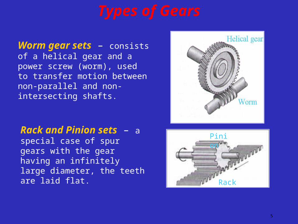
Worm gear sets – consists of a helical gear and a power screw (worm), used to transfer motion between non-parallel and non-intersecting shafts.
Rack and Pinion sets – a special case of spur gears with the gear having an infinitely large diameter, the teeth are laid flat.
Rack
Pinion

6
Gear Design and Analysis
• Kinematics of gear teeth and gear trains.
• Force analysis.
• Design based on tooth bending strength.
• Design based on tooth surface strength.
7
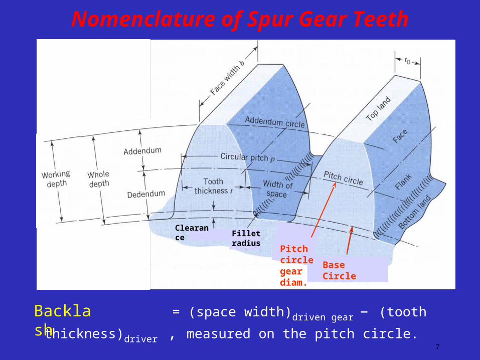
Nomenclature of Spur Gear Teeth
= (space width)driven gear – (tooth thickness)driver , measured on
the pitch circle.
Backlash
Pitch circle gear diam.
Fillet radiusClearance
Base Circle

8
• Pitch cylinders – are imaginary friction cylinders which by pure rolling together transmit same motion as the pair of gears
• Pitch circle – It is the circle corresponding to a section of the equivalent pitch cylinder by a plane normal to the wheel axis
• Pitch diameter – It is the diameter of the pitch cylinder
• Pitch point - The point of contact of two pitch circles.
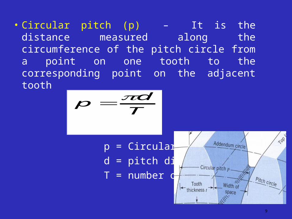
• Circular pitch (p) – It is the distance measured along the circumference of the pitch circle from a point on one tooth to the corresponding point on the adjacent tooth
p = Circular pitch
d = pitch diameter
T = number of teeth
9
T
dp
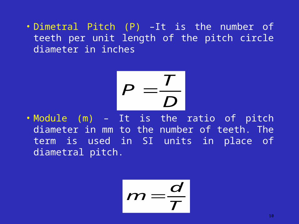
• Dimetral Pitch (P) –It is the number of teeth per unit length of the pitch circle diameter in inches
• Module (m) – It is the ratio of pitch diameter in mm to the number of teeth. The term is used in SI units in place of diametral pitch.
10
T
dm
D
TP
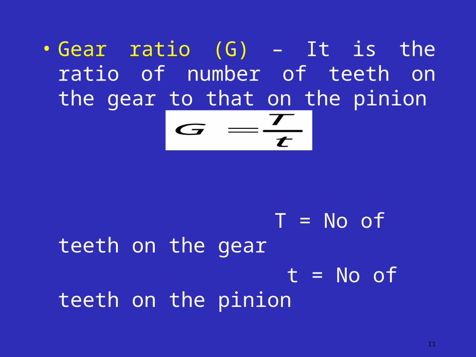
• Gear ratio (G) – It is the ratio of number of teeth on the gear to that on the pinion
T = No of teeth on the gear
t = No of teeth on the pinion
11
t
TG
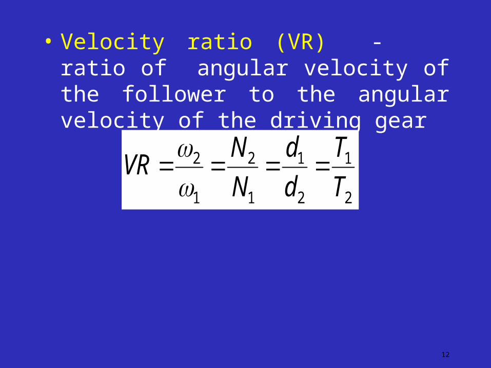
• Velocity ratio (VR) - ratio of angular velocity of the follower to the angular velocity of the driving gear
12
2
1
2
1
1
2
1
2
T
T
d
d
N
NVR
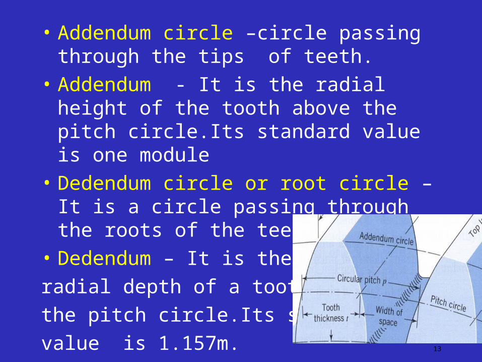
• Addendum circle –circle passing through the tips of teeth.
• Addendum - It is the radial height of the tooth above the pitch circle.Its standard value is one module
• Dedendum circle or root circle – It is a circle passing through the roots of the teeth.
• Dedendum – It is the
radial depth of a tooth below
the pitch circle.Its standard
value is 1.157m.13
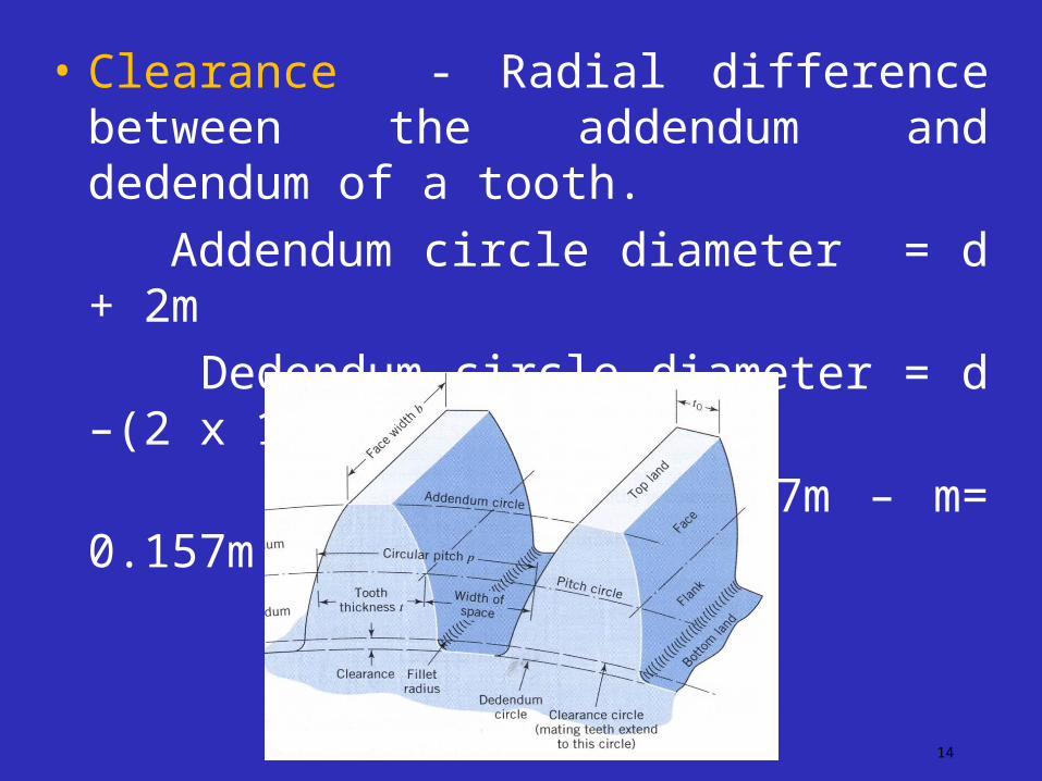
• Clearance - Radial difference between the addendum and dedendum of a tooth.
Addendum circle diameter = d + 2m
Dedendum circle diameter = d –(2 x 1.157 m)
Clearance = 1.157m – m= 0.157m
14
• Full depth of teeth - It is the total radial depth of tooth space
Full depth = Addendum + Dedendum
Working depth of teeth – The maximum depth to which a tooth penetrates into tooth space of the mating gear is the working depth of teeth.
Space width – It is the width of the tooth space along the pitch circle.
Tooth thickness . It is the thickness of the tooth measured along the pitch circle
Backlash = (space width)driven gear – (tooth thickness)driver , measured on the pitch circle. 15

• Face width - The length of the
Tooth parallel to the gear axis
Top land - it is the surface of the
top of the tooth.
Bottom land – Surface of the
Bottom of the tooth the adjacent
Fillets
Face -Tooth surface between pitch circle and top land.
Flank –Tooth surface between the pitch circle and bottom land including fillet
Fillet- curved portion of tooth flank at the root circle16

17
Nomenclature of Spur Gear Teeth
= (space width)driven gear – (tooth thickness)driver , measured on
the pitch circle.
Backlash
Pitch circle gear diam.
Fillet radiusClearance
Base Circle
18
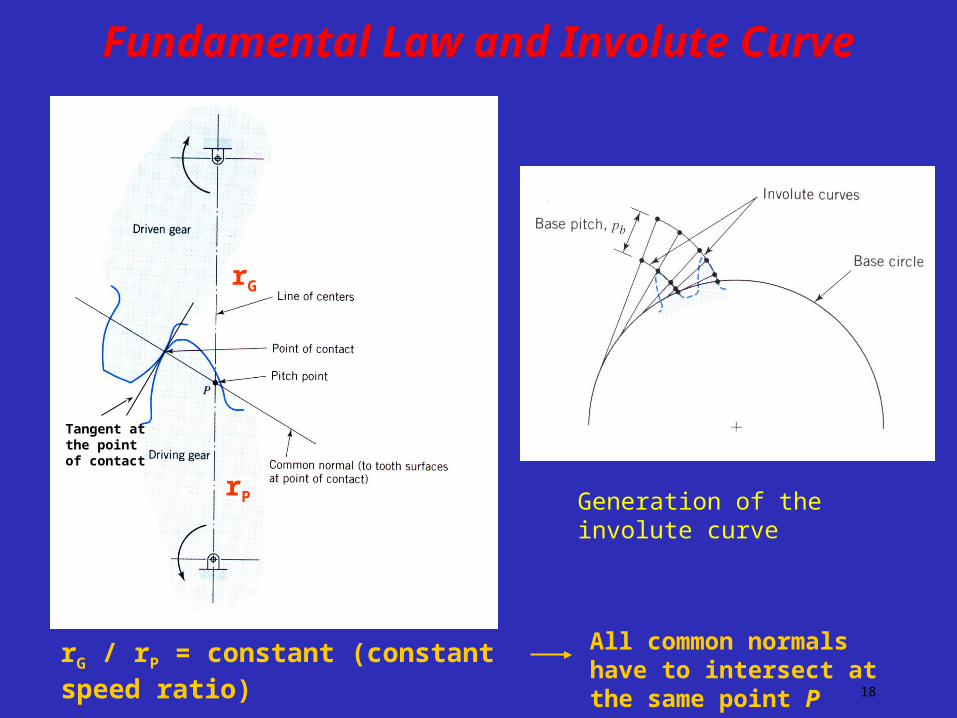
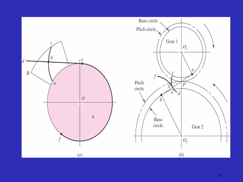
Fundamental Law and Involute Curve
Generation of the involute curve
Tangent at the point of contact
rG
rP
rG / rP = constant (constant speed ratio) All common normals have to intersect at the same point P
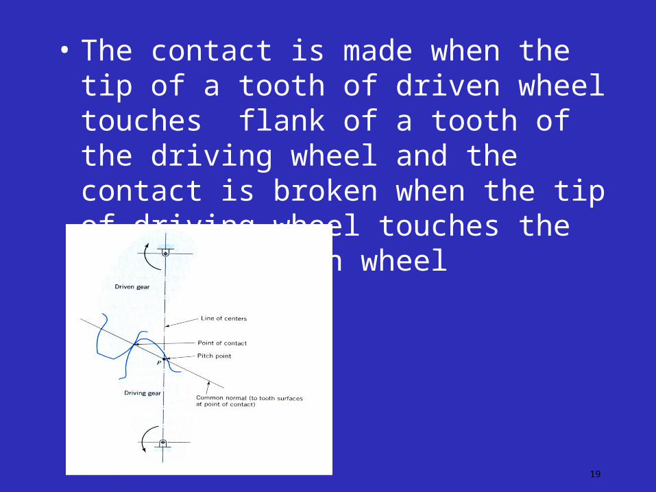
• The contact is made when the tip of a tooth of driven wheel touches flank of a tooth of the driving wheel and the contact is broken when the tip of driving wheel touches the flank of driven wheel
19

• Line of Action or pressure line – The force which the driving tooth exerts on the driven tooth is along a line from the pitch point to the point of contact of two teeth.
• Pressure angle (φ) –The angle between the pressure line and the common tangent to the pitch circle.
• Path of contact or Contact length – The locus of the point of contact of two mating teeth from the beginning of engagement to the end of engagement is known as the path of contact or the contact length.It is CD
20

21

Path of contact can be subdivided as
Path of approach - length CP
Path of recess – length PD
Arc of contact – The locus of a point on the pitch circle from the beginning to the end of engagement of two mating gears .APB or EPF
Arc of approach – It is the portion of arc of contact from the beginning of engagement to the pitch point. Length AP or EP
Arc of recess-The portion of the arc of contact from the pitch point to the engagement .Length PB or PF
22

• Angle of action (Ϩ).Angle turned by a gear from the beginning of engagement to the end of engagement of a pair of teeth.
Angle of approach (α) ,angle of recess (β)
Ϩ = α + β
Contact ratio = Arc of contact / circular pitch
23

LAW OF GEARING
The common normal at the point of contact of the two teeth should always pass through a fixed point(pitch point) which divides the line of centres in the inverse ratio of angular velocities of two gears.
24
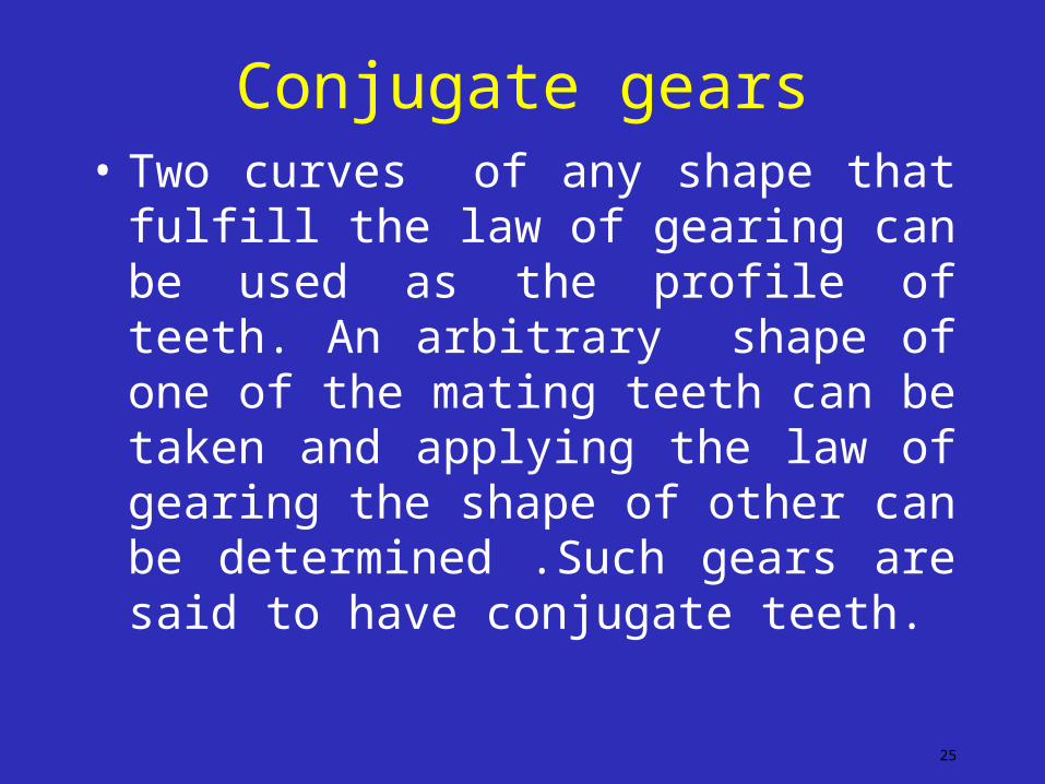
Conjugate gears• Two curves of any shape that fulfill the law
of gearing can be used as the profile of teeth. An arbitrary shape of one of the mating teeth can be taken and applying the law of gearing the shape of other can be determined .Such gears are said to have conjugate teeth.
25

Common forms of teeth
1. Cycloidal profile teeth
2. Involute profile teeth
26
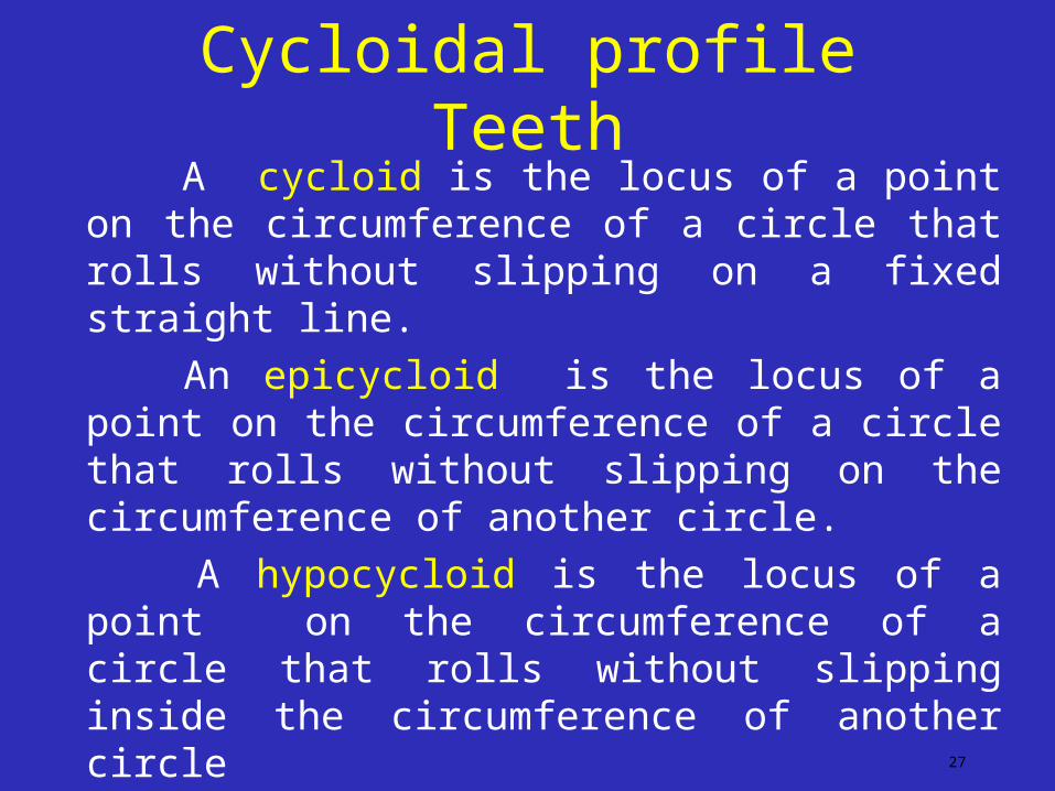
Cycloidal profile Teeth A cycloid is the locus of a point on the
circumference of a circle that rolls without slipping on a fixed straight line.
An epicycloid is the locus of a point on the circumference of a circle that rolls without slipping on the circumference of another circle.
A hypocycloid is the locus of a point on the circumference of a circle that rolls without slipping inside the circumference of another circle
27

28

Meshing of cycloidal teeth
29

Properties of cycloidal teeth• Common normal to the two meshing curves
Passes through the pitch point.
• Pressure angle varies from maximum at the beginning of engagement to zero when point of contact coincides with pitch point and increases in the reverse direction.
• Cycloidal teeth are made of two curves ,hyocycloid and epicycloid it is difficult top produce accurate profiles
30
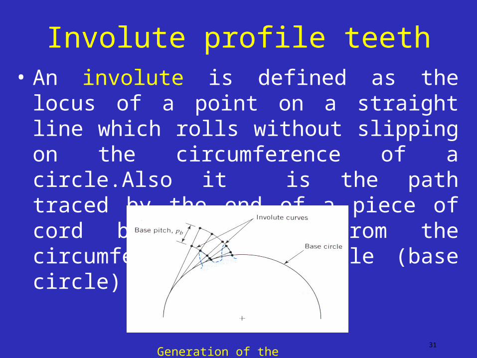
Involute profile teeth• An involute is defined as the locus of a point on a
straight line which rolls without slipping on the circumference of a circle.Also it is the path traced by the end of a piece of cord being unwound from the circumference of a circle (base circle)
31Generation of the involute curve
32

33

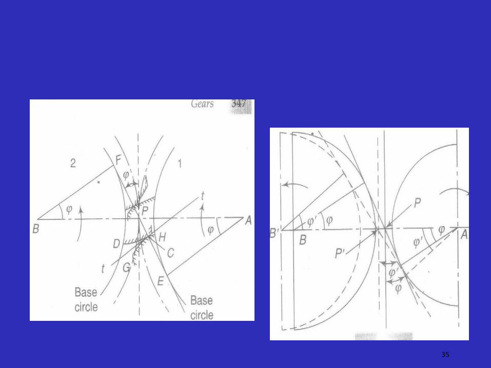
Properties of Involute teeth
• Normal to the involute curve is tangent to the base circle.
• Common normal to the two involutes divides the line of centres of the two gears at P (Pitch point).Common normal passes through the pitch point.
34
35
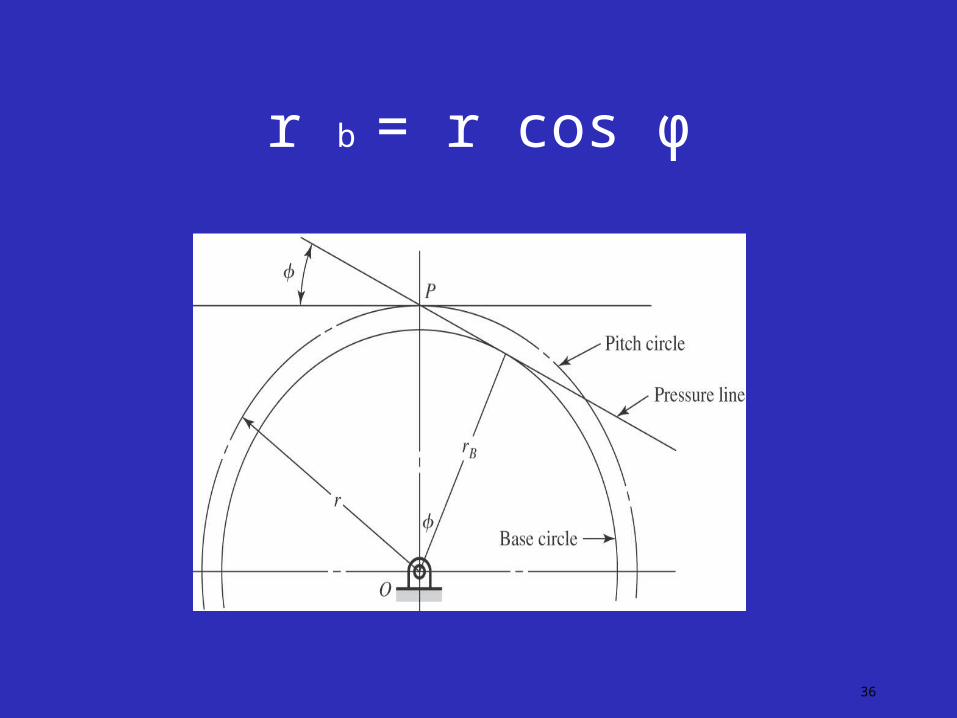
r b = r cos φ
36
• Line of action in case of two involute curve is along the common normal at the point of contact which is fixed and is common tangent to base circles.Thus pressure angle remains constant through out engagement.
• Shifting of centre distance doesnot affect the velocity ratio
37
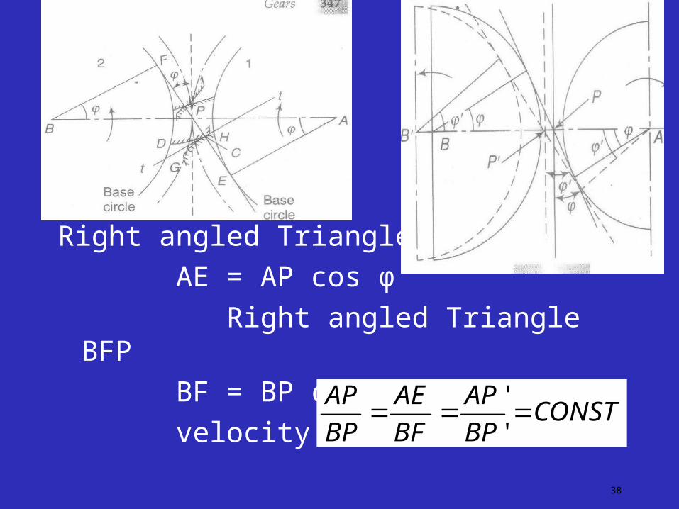
Right angled Triangle AEP
AE = AP cos φ
Right angled Triangle BFP
BF = BP cos φ
velocity ratio =
38
CONSTBP
AP
BF
AE
BP
AP
'
'

Standard gears
• The same module
• The same pressure angle
• The same addendums and dedendums
• The same thickness
Standard pressure angles, 14.5o (old), 20o,22.5 0 and 25o
39
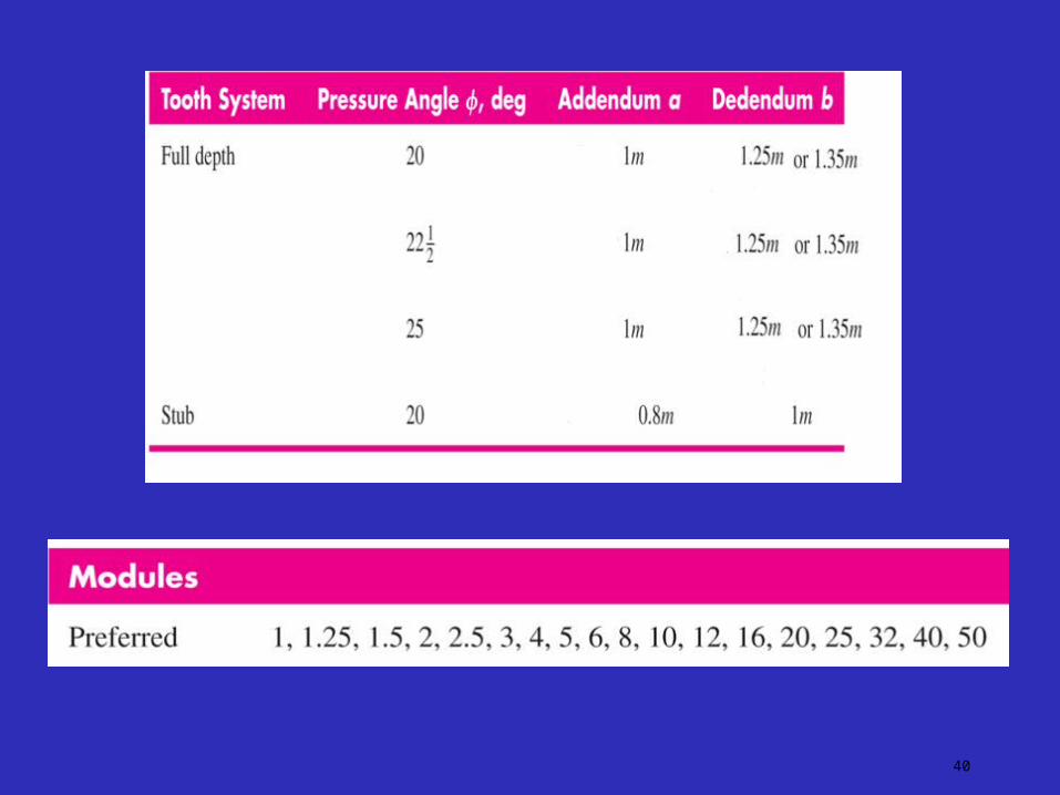
40

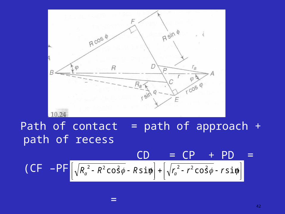
Length of path of contact
41
• Gear 1 driver (pinion) Gear 2 is wheel driven
Let r = pitch circle radius of pinoin
R =pitch circle radius of wheel
r a = addendum circle radius of pinion
Ra = addendum circle radius of wheel
42
Path of contact = path of approach + path of recess
CD = CP + PD = (CF –PF) + (DE –PE)
=
sincossincos 222222 rrrRRR aa
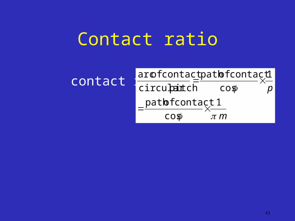
Contact ratio
contact ratio (n) =
43
m
p
1
cos
contact ofpath
1
cos
contact ofpath
pitchcircular
contact of arc
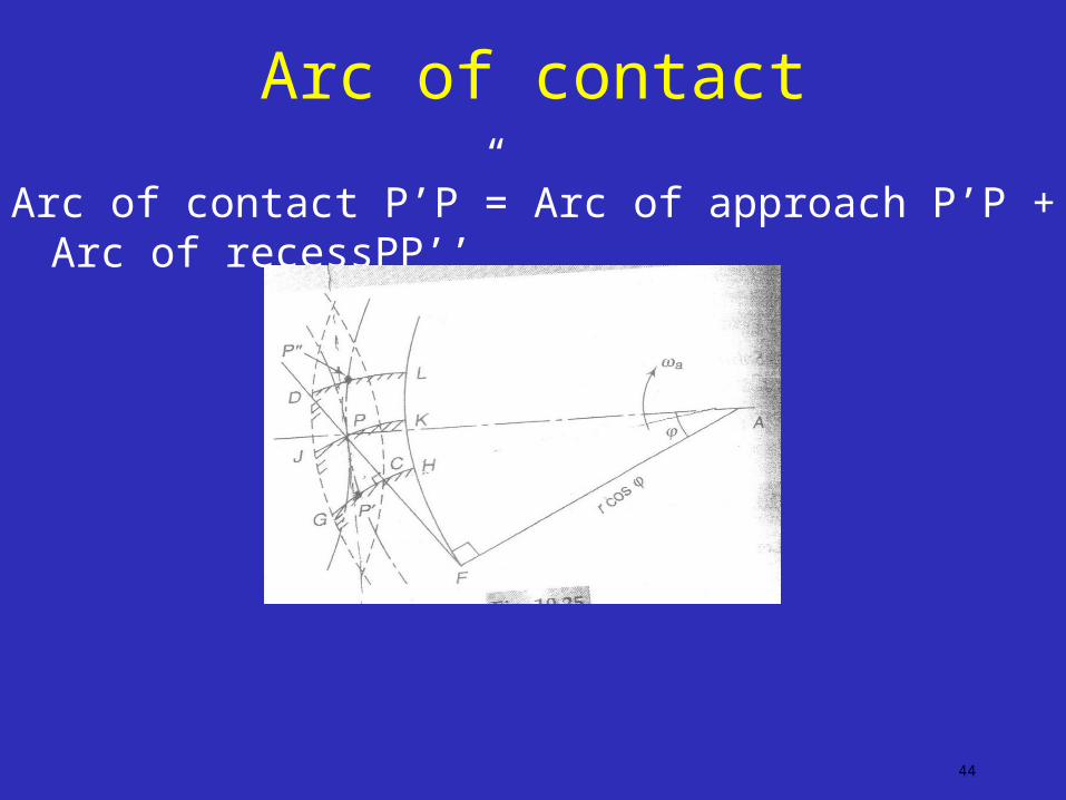
Arc of contact
Arc of contact P’P”= Arc of approach P’P + Arc of recessPP’’
44
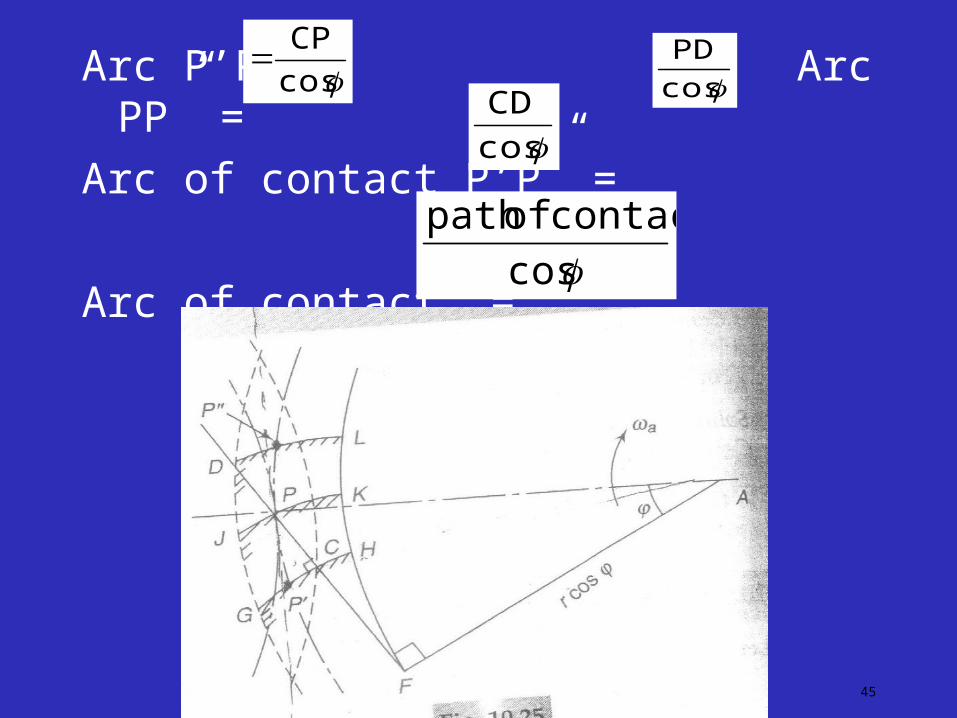
45
Arc P’P Arc PP” =
Arc of contact P’P” =
Arc of contact =
cos
CP
cos
PD
cos
CD
cos
contact ofpath

• Contact ratio indicate no of pairs of teeth in contact.
• For continous transmission of motion there should be atleast one pair of teeth which are always in contact.so contact ratio has to be more than one.
• If n is 1.6 ,one pair of teeth are always in contact whereas two pairs of teeth are in contact for 60% of the time
46
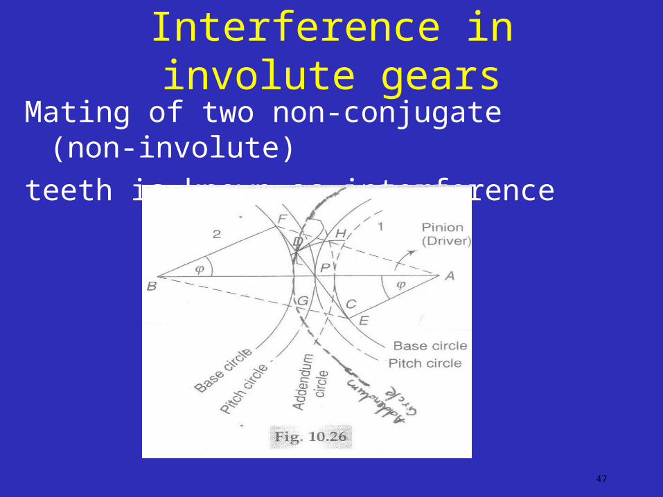
Interference in involute gears
47
Mating of two non-conjugate (non-involute)
teeth is known as interference

48
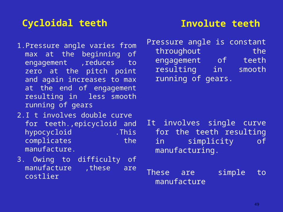
Cycloidal teeth
1.Pressure angle varies from max at the beginning of engagement ,reduces to zero at the pitch point and again increases to max at the end of engagement resulting in less smooth running of gears
2.I t involves double curve for teeth.,epicycloid and hypocycloid .This complicates the manufacture.
3. Owing to difficulty of manufacture ,these are costlier
Involute teeth
Pressure angle is constant throughout the engagement of teeth resulting in smooth running of gears.
It involves single curve for the teeth resulting in simplicity of manufacturing.
These are simple to manufacture
49
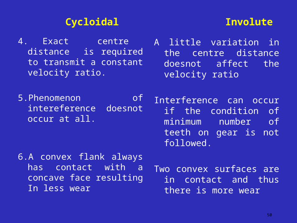
Cycloidal
4. Exact centre distance is required to transmit a constant velocity ratio.
5.Phenomenon of intereference doesnot occur at all.
6.A convex flank always has contact with a concave face resulting In less wear
Involute
A little variation in the centre distance doesnot affect the velocity ratio
Interference can occur if the condition of minimum number of teeth on gear is not followed.
Two convex surfaces are in contact and thus there is more wear
50