geothermal drilling in enel green power - · pdf filegeothermal drilling in enel green power...
TRANSCRIPT

Geothermal drilling in Enel Green PowerEGP well schemes, directional drilling, multilateral technology
Larderello, 11th October 2013Larderello, 11th October 2013

EGP standard geothermal well
Well diagram
3000/5000 psi
NEOGENE
FLYSCHCALCAREOMARNOSO
SCAGLIETETTONICHE(SERIE ANIDRITICA
VERRUCANO)
BASAMENTO(FILLADI
500
1000
1500
100 30”
600
23”
1500
17”1/2
24”1/2
18”5/8
13”3/8
November 2010 2
(FILLADIMICASCISTI
GNEISS)2000
2500
3000
3500
2400
12”1/4
3500
8”1/2
9”5/8

Steam cleaning system
Surface equipment
5
Gravity/centrifugal separators
Well heads
Silencers
Water
Steam
2
3
4
November 2010 3
NaOH bailers/cleaning solution preparation
1
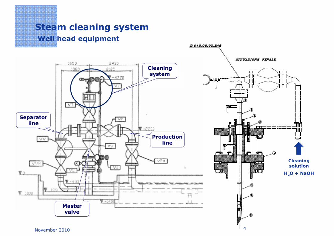
Steam cleaning system
Well head equipment
Cleaning system
Production line
Separator line
November 2010 4
Cleaning solution
H2O + NaOH
Master valve

Steam cleaning system
Hole equipment
Pip
es
In
jecti
on
head
November 2010 5
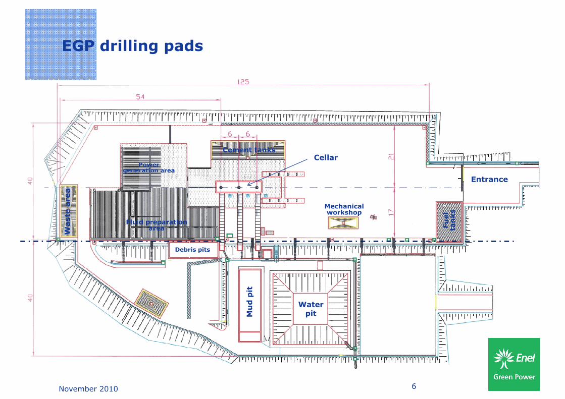
EGP drilling pads
Entrance
Debris pits
Cellar
Mechanical workshop
Fu
el
ta
nks
Waste
area
Power generation area
Fluid preparation area
Cement tanks
November 2010 6
WaterpitM
ud
pit
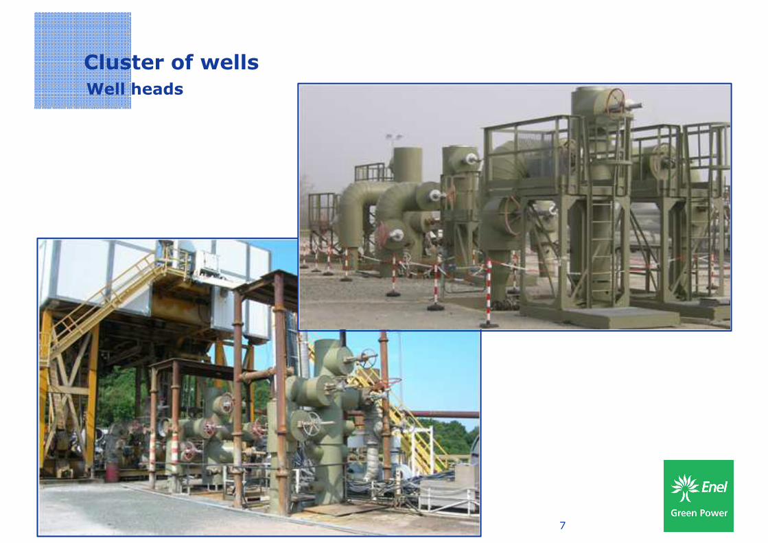
Cluster of wells
Well heads
November 2010 7

Mining targets
November 2010 8

Mining target
Horizontal section
RAD_17BTR_15
TR_16
TR_3BISTRBCF_3
1666000 1666080 1666160 1666240 1666320 1666400 1666480 1666560 1666640 1666720 1666800 1666880 1666960 1667040 1667120 1667200 1667280 1667360 1667440 1667520 1667600 1667680 1667760 1667840
4782
960
4783
040
47829604783040
RAD_7BIS
RAD_17D_R1
TR_12
TR_15
TR_17
TRHN_2
MD: 2335.00
MD: 2410.00
MD: 2660.00
MD: 2900.00
MD: 3400.00
MD: 3150.00
MD: 3650.00
4782
320
4782
400
4782
480
4782
560
4782
640
4782
720
4782
800
4782
880
47823204782400
47824804782560
47826404782720
47828004782880
MON_5A
November 2010 9
MON_5
1666000 1666080 1666160 1666240 1666320 1666400 1666480 1666560 1666640 1666720 1666800 1666880 1666960 1667040 1667120 1667200 1667280 1667360 1667440 1667520 1667600 1667680 1667760 1667840
4781
840
4781
920
4782
000
4782
080
4782
160
4782
240
47818404781920
47820004782080
47821604782240
0 100 200 300m
1:5000
Target
Wellhead

Mining target
Vertical section
3600 3800 4000 4200 4400 4600 4800 5000 5200 5400 5600 5800 6000 6200
020
0
0200
-800
-600
-400
-200
-800-600
-400-200
MARKER H
November 2010 10
MON_5
RAD_7BIS
TR_SUD_1TR_SUD_1B
TR_SUD_1C_R1MON_5A
3600 3800 4000 4200 4400 4600 4800 5000 5200 5400 5600 5800 6000 6200
-140
0-1
200
-100
0
-1400-1200
-1000
Target

Directional drilling
Directional drilling allows to reach a mining target off line with respect to thevertical axis of the well (offset up to 2000 m)
Deviation program is generally divided into 3 steps:
Phases
Deviation program is generally divided into 3 steps:
KICKOFF POINT
. BUILD-UP
• Drilling of the first vertical section till kick off point (KOP)
• Build-up phase (increase of the angle) where the well inclination is gradually increased to the design value
November 2010 11
.
.MAINTENANCE .
TOTAL VERTICAL DEPT
FINAL INCLINATION
increased to the design value
• Maintenance phase where inclination and direction of the well remain the same till the reaching of the target

Directional drilling
• MUD MOTOR
Used both in the build up phase and in the maintenance phase. Itis set just above the rock bit with the purpose to give it therotation keeping the rest of the drilling string still
Tools
DRILL COLLARS
DRILL PIPES
rotation keeping the rest of the drilling string still
• BENT HOUSING
It is used to facilitate the exit from the vertical axis of the well;generally it has an inclination between 1,5° and 2°
• MWD (Measurement While Drilling)
Performs the measurement of the inclination and direction of thewell real time. The tool has a “pulsar” set above the Mud Motorand a receiver at the surface that works as a decoder of the signalcoming through the drilling fluid
MWD
MUD MOTOR
November 2010 12
coming through the drilling fluid
ROCK BIT
MUD MOTOR

Directional drilling
Well plan
-1400 -1200 -1000 -800 -600 -400 -200 0
N
Design path
400
600
800
1889
2085
2331
2584
2823
3088
3424
Real path
Design path
Real path
November 2010
0
200
974
1292
1500
1704
1889
E
Wellhead
Design path

Exploitation of the field
Complexity
4787000
2510
Well head
Measured Depth [m] n.
4783000
4784000
4785000
4786000
3210
2749
3941
23042234
3314
2893
4077
3621
3891
27722772
2299
2555
27112671
3502
2591
Gauss B
oaga
Nort
h [
m]
November 2010 141660000 1661000 1662000 1663000 1664000 1665000 1666000 1667000 1668000 1669000 1670000 1671000
4780000
4781000
4782000
2586
2861
27243556
2990
Gauss
Gauss Boaga Est [m]

Drilling pad
Complexity Well head
Measured Depth [m] n.
4780840
1676
2044
986
1125
1239
1385
1443
Gauss B
oaga
Nort
h [
m]
4780800
4780810
4780820
4780830
916
1112
1414
710
8861008
1064
1113
1150
819
986
900
1029
1147
900
1029
1215
1272
1333
398
508
757
948
1223
1261
1298
1329
1357Well 5
Rig footprint
November 2010 15
Gauss
1667740 1667750 1667760 1667770 1667780 1667790 1667800 1667810 1667820 1667830 1667840 1667850
4780780
4780790
4521187
1224
750750
398
1384
1412
1439
Well 1
Well 2
Well 3
Well 4 Natural deviation
Gauss Boaga Est [m]

Risk of collision
High risk High risk of
collision
November 2010 16

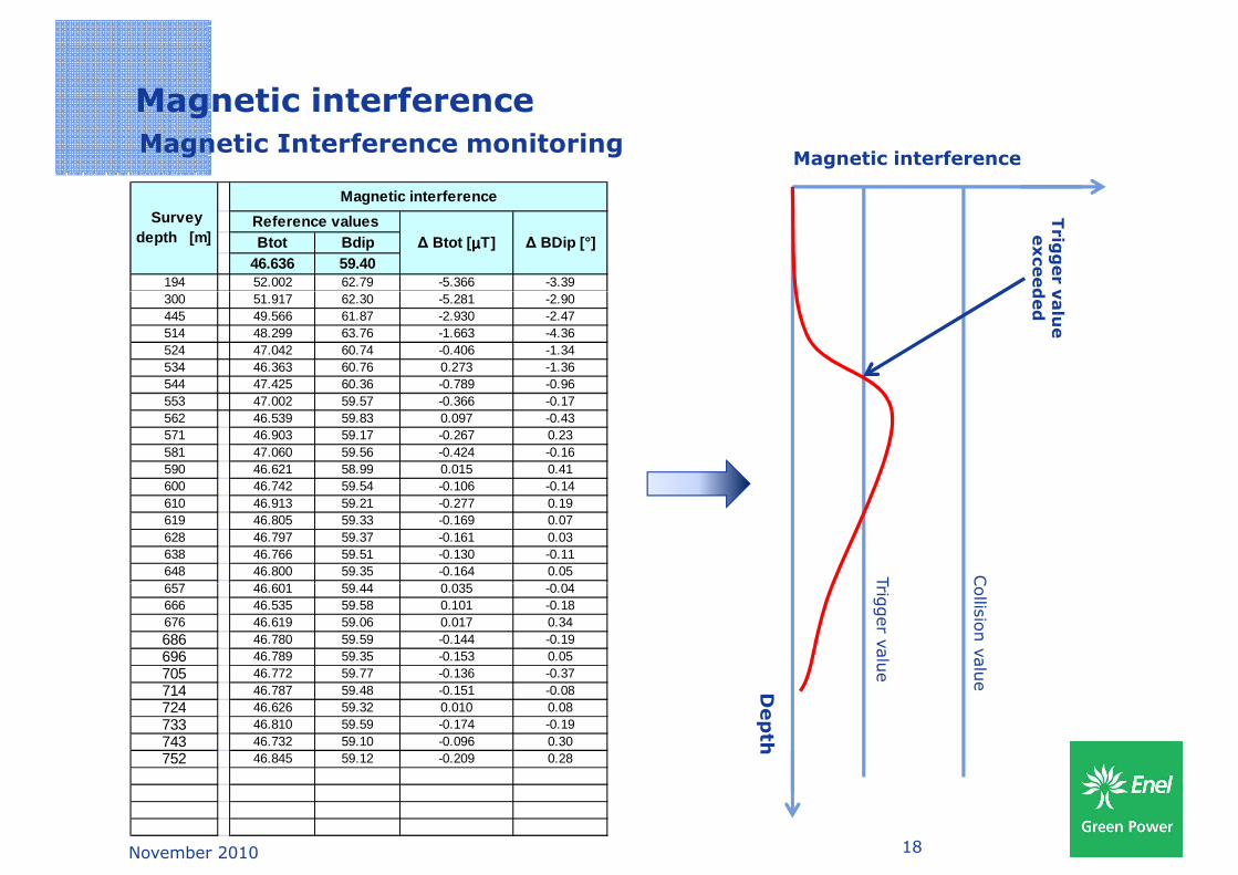
Magnetic interference
Survey report
BTOTAL – Magnetic flux density
B – Magnetic field dip
Time Depth (m) Gtot Btot GTF Incl Az Dip
1st
15:53:59 199.00 1.002 51.191 96.95 7.44 124.54 62.38
15:54:59 199.00 1.003 51.159 96.43 7.49 124.98 62.47
15:55:59 199.00 1.002 51.191 96.78 7.46 124.71 62.41
15:56:59 199.00 1.002 51.192 96.47 7.46 125.12 62.44
Average value 1.002 51.183 96.66 7.46 124.84 62.43
Survey report
November 2010 17
BDIP – Magnetic field dip
BTOTAL (Measured) vs BTOTAL (Local)
BDIP (Measured) vs BDIP (Local)MagneticMagnetic InterferenceInterference
Magnetic interference
Magnetic Interference monitoringMagnetic interference
Trig
ger v
alu
e
exceed
ed
Btot Bdip46.636 59.40
194 52.002 62.79 -5.366 -3.39
Survey depth [m]
Magnetic interference
Reference values∆ Btot [ µµµµT] ∆ BDip [°]
Trig
ger v
alu
e
Collis
ion v
alu
e
Trig
ger v
alu
e
exceed
ed300 51.917 62.30 -5.281 -2.90
445 49.566 61.87 -2.930 -2.47514 48.299 63.76 -1.663 -4.36524 47.042 60.74 -0.406 -1.34534 46.363 60.76 0.273 -1.36544 47.425 60.36 -0.789 -0.96553 47.002 59.57 -0.366 -0.17562 46.539 59.83 0.097 -0.43571 46.903 59.17 -0.267 0.23581 47.060 59.56 -0.424 -0.16590 46.621 58.99 0.015 0.41600 46.742 59.54 -0.106 -0.14610 46.913 59.21 -0.277 0.19619 46.805 59.33 -0.169 0.07628 46.797 59.37 -0.161 0.03638 46.766 59.51 -0.130 -0.11648 46.800 59.35 -0.164 0.05657 46.601 59.44 0.035 -0.04
November 2010 18
Dep
th
Trig
ger v
alu
e
Collis
ion v
alu
e
657 46.601 59.44 0.035 -0.04666 46.535 59.58 0.101 -0.18676 46.619 59.06 0.017 0.34686 46.780 59.59 -0.144 -0.19696 46.789 59.35 -0.153 0.05705 46.772 59.77 -0.136 -0.37714 46.787 59.48 -0.151 -0.08724 46.626 59.32 0.010 0.08733 46.810 59.59 -0.174 -0.19743 46.732 59.10 -0.096 0.30752 46.845 59.12 -0.209 0.28

Multilateral technology
November 2010 19
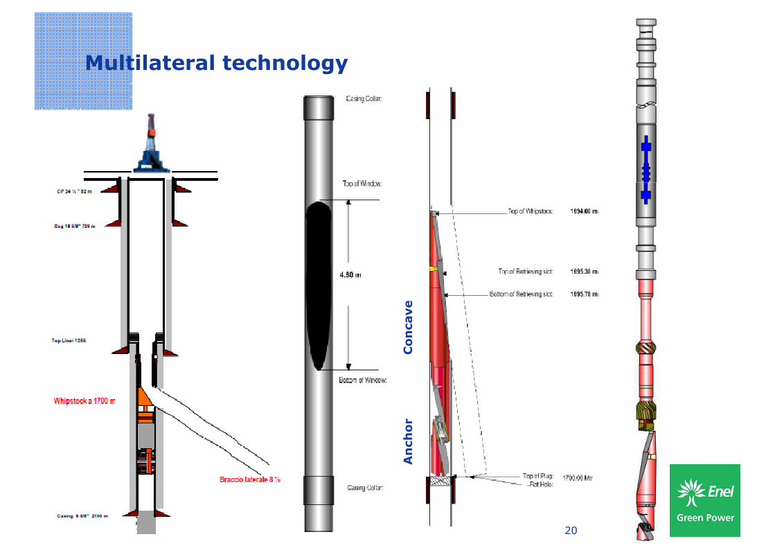
Multilateral technology
Co
ncave
November 2010 20
An
ch
or

Multilateral technology
Sequence of operations
1. Multifinger
2. Set Packer
3. Cement plug3. Cement plug
4. Gauge Run + Scraper
5. Orient Whipstock (Multishot)
6. Set Whipstock (release 3 t to break shear pins)
7. Release 20 t to break shear bolt between Mill and Concave
8. Rat hole
9. POOH
November 2010 21
9. POOH
10. Run BHA for directional drilling
11. Drilling of the new branch

Multilateral technology
Retrieving systems
Concave Anchor
Ho
ok
Die
co
llar
QuickChangeAdapter
Retrieving slot
1
2
November 2010 22
1
3

N
MV 3C - Actual branch
Multilateral technology
Case study - Monteverdi 3C
E
November 2010
MV 3C - New branch
23
Kick Off Point 1750m