hfss 基础培训教程 建模 - mweda · hfss 基础培训教程 ... – create multiple copies of...
TRANSCRIPT

© 2011 ANSYS, Inc. All rights reserved. 1 ANSYS, Inc. Proprietary© 2011 ANSYS, Inc. All rights reserved. 1 ANSYS, Inc. Proprietary
HFSS 基础培训教程
建模、预处理
ANSYS 中国
© 2011 ANSYS, Inc. All rights reserved. 2 ANSYS, Inc. Proprietary
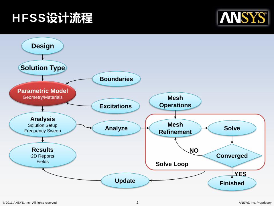
HFSS设计流程
Design
Solution Type
Parametric ModelGeometry/Materials
AnalysisSolution Setup
Frequency Sweep Analyze
Results2D Reports
Fields
Boundaries
Excitations
MeshRefinement Solve
MeshOperations
Converged
FinishedUpdate
NO
YESSolve Loop

© 2011 ANSYS, Inc. All rights reserved. 3 ANSYS, Inc. Proprietary
• 模型预览New
• 用户自定义键盘快捷键 New
桌面增强功能
© 2011 ANSYS, Inc. All rights reserved. 4 ANSYS, Inc. Proprietary
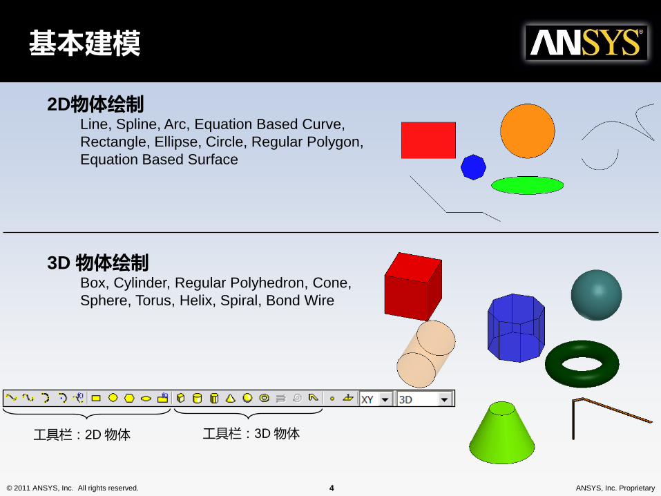
基本建模
工具栏:2D 物体 工具栏:3D 物体
2D物体绘制Line, Spline, Arc, Equation Based Curve, Rectangle, Ellipse, Circle, Regular Polygon, Equation Based Surface
3D 物体绘制Box, Cylinder, Regular Polyhedron, Cone, Sphere, Torus, Helix, Spiral, Bond Wire

© 2011 ANSYS, Inc. All rights reserved. 5 ANSYS, Inc. Proprietary
建模——布尔操作、模型变换
• Modeler > Boolean >– Unite – combine multiple primitives
• Unite disjoint objects (Separate Bodies to separate)– Subtract – remove part of a primitive from another– Intersect– keep only the parts of primitives that overlap– Split – break primitives into multiple parts along a plane (XY, YZ, XZ)– Split Crossing Objects – splits objects along a plane (XY, YZ, XZ) only where they intersect– Separate Bodies – separates objects which are united but not physically connected into individual objects
• Modeler > Surfaces > Move Faces – Resize or Reposition an objects face along a normal or vector.
• Edit > Arrange >– Move – Translates the structure along a vector– Rotate – Rotates the shape around a coordinate axis by an angle– Mirror – Mirrors the shape around a specified plane– Offset – Performs a uniform scale in x, y, and z.
• Edit > Duplicate >– Along Line – Create multiple copies of an object along a vector– Around Axis – Create multiple copies of an object rotated by a fixed angle around the x, y, or z axis– Mirror - Mirrors the shape around a specified plane and creates a duplicate
• Edit > Scale – Allows non-uniform scaling in the x, y, or z direction
Toolbar: Boolean
Toolbar: Arrange
Toolbar: Duplicate

© 2011 ANSYS, Inc. All rights reserved. 6 ANSYS, Inc. Proprietary
• Polyline Cross Section New
– Choose Cross Section Type and Size• Type: Line, Rectangle, Circle• Size can be a variable
– Section is automatically swept along the polyline
1. Create a Polyline 2. Set Cross Section Property 3. Polyline with Cross Section Property

© 2011 ANSYS, Inc. All rights reserved. 7 ANSYS, Inc. Proprietary
倒角和圆角
• Create Chamfers and Fillets on 3D or 2D Objects– Select a vertex graphically and choose the menu item:
• Fillet or Chamfer
Chamfer - 45 degree cut
Fillet- Rounded edge
Original
© 2011 ANSYS, Inc. All rights reserved. 8 ANSYS, Inc. Proprietary
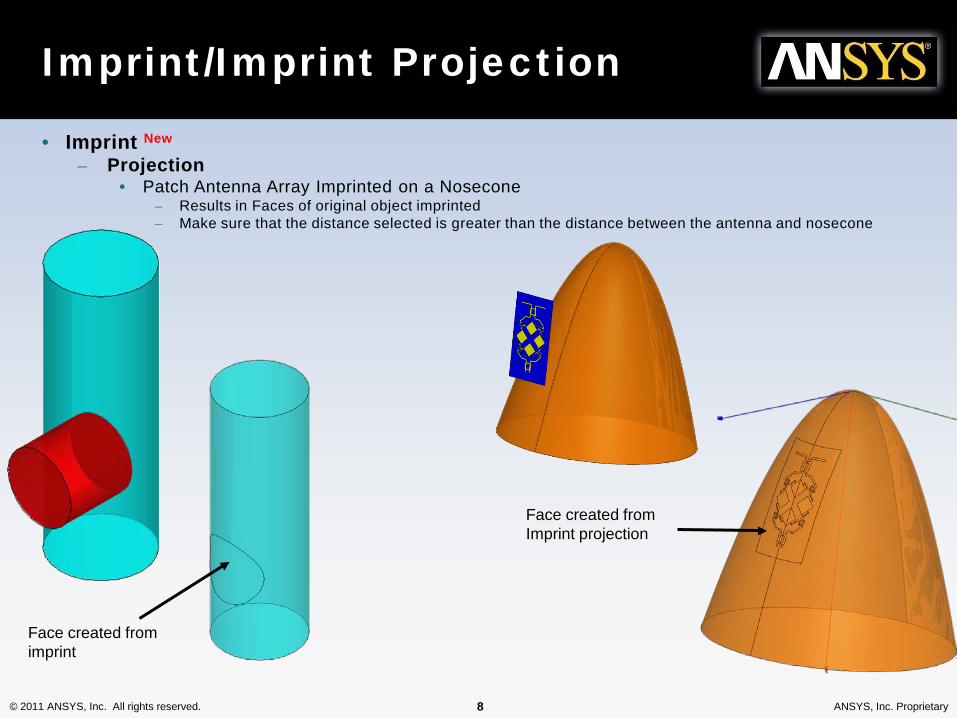
Imprint/Imprint Projection
• Imprint New
– Projection• Patch Antenna Array Imprinted on a Nosecone
– Results in Faces of original object imprinted– Make sure that the distance selected is greater than the distance between the antenna and nosecone
Face created from imprint
Face created from Imprint projection

© 2011 ANSYS, Inc. All rights reserved. 9 ANSYS, Inc. Proprietary
• Geometry Wrap New
– Wrap a 2D sheet on an arbitrary geometry
Slot Coupled Patch Array wrapped on a cylinder

© 2011 ANSYS, Inc. All rights reserved. 10 ANSYS, Inc. Proprietary
Modeler - Selection
• Selection Type– Object (Default)、Face、Edge、Vertex
• Selection Modes– All Objects、All Visible Object、By Name
• Highlight Selection Dynamically – – By default, moving the mouse pointer over an object will dynamically highlight the
object for selection. To select the object simply click the left mouse button.– Multiple Object Selection – Hold the CTRL key down to graphically select multiple
objects– Next Behind – To select an object located behind another object, select the front
object, press the b key to get the next behind. Note: The mouse pointer must be located such that the next behind object is under the mouse pointer.
– To Disable: Select the menu item Tools > Options > 3D Modeler Options• From the Display Tab, uncheck Highlight selection dynamically
Dynamically Highlighted(Only frame of object)
Selected

© 2011 ANSYS, Inc. All rights reserved. 11 ANSYS, Inc. Proprietary
Enhanced Selection Options
• Enhanced Selection Options New
– Select By Area• Click and drag to rubber-band select
– Right-to-left selects all objects in passing through bounding box– Left-to-right select all objects enclosed by bounding box
– Select By Variable• Helps find objects tied to variables
– Select Variable and Click OK to highlight geometry
• Select By Area– By default, only items with external surfaces are selected
• Material filters – Enable the Include and Exclude radio buttons
• Object name filters – Enable the Exclude and Include check boxes
• Object type filters – Enable the check boxes for including Solids, Sheets,
and/or Lines
• Hide unfiltered objects – Makes unfiltered objects transparent after selection
© 2011 ANSYS, Inc. All rights reserved. 12 ANSYS, Inc. Proprietary
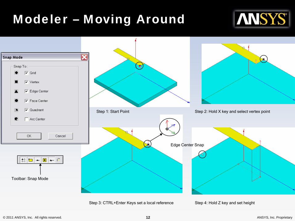
Modeler – Moving Around
Step 1: Start Point Step 2: Hold X key and select vertex point
Step 3: CTRL+Enter Keys set a local reference Step 4: Hold Z key and set height
Edge Center Snap
Toolbar: Snap Mode

© 2011 ANSYS, Inc. All rights reserved. 13 ANSYS, Inc. Proprietary
• Modeler > Measure >
– Position – Points and Distance– Length – Edge Length– Area – Surface Area– Volume – Object Volume
Modeler – Measure

© 2011 ANSYS, Inc. All rights reserved. 14 ANSYS, Inc. Proprietary
Step 1: Select Face Step 2: Select Origin
Step 3: Set X-Axis New Working CS
Modeler – Coordinate System
• Can be Parameterized• Working Coordinate System
– Currently selected CS. This can be a local or global CS• Global CS
– The default fixed coordinate system• Relative CS
– User defined local coordinate system.• Offset• Rotated• Both
• Face CS (setting available to automatically switch to face coordinate system in the 3D Modeler Options)
Cone created with Face CS
Change Box Size and Cone is automatically positioned with the top face of the box
Toolbar: Coordinate System
© 2011 ANSYS, Inc. All rights reserved. 16 ANSYS, Inc. Proprietary
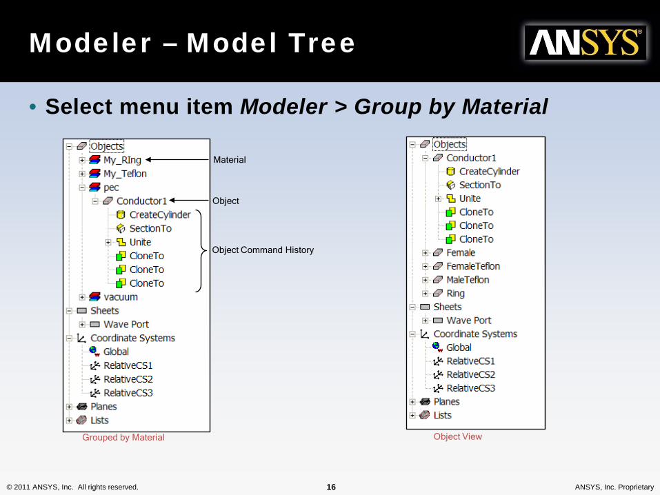
Modeler – Model Tree
• Select menu item Modeler > Group by Material
Grouped by Material
Material
Object
Object Command History
Object View

© 2011 ANSYS, Inc. All rights reserved. 17 ANSYS, Inc. Proprietary
参数化建模
• Parametric Technology– Dynamic Edits - Change Dimensions– Add Variables
• Project Variables (Global), Design Variables (Local), or Post Processing Variables
• Animate Geometry• Include Units – Default Unit is meters
– Supports mixed Units

© 2011 ANSYS, Inc. All rights reserved. 18 ANSYS, Inc. Proprietary
Post-Processing Variables
• Post Processing Variables New
– Can be modified without re-simulating the model– Can optimize complex weights of antenna elements in phased array
Optimization of Phased Array Excitations
Synthesized Far-field Pattern Specify Desired Scan Angle and Maximum Sidelobe Level

© 2011 ANSYS, Inc. All rights reserved. 19 ANSYS, Inc. Proprietary
Automatic Feature Removal
Holes
Blends
Step 1: Enter Feature Detection Options

© 2011 ANSYS, Inc. All rights reserved. 20 ANSYS, Inc. Proprietary
Automatic Feature Removal
RemovedNote: There are two modes of operation for the feature removal: Healingand Model Analysis. Model Analysis was used here and allows the user tomanually select which geometry features are removed. For healing, allfeatures that meet the user defined criteria are automatically removed.Both options are found in the menu item Modeler > Model Analysis
Step 2: Select Features to Remove
© 2011 ANSYS, Inc. All rights reserved. 21 ANSYS, Inc. Proprietary
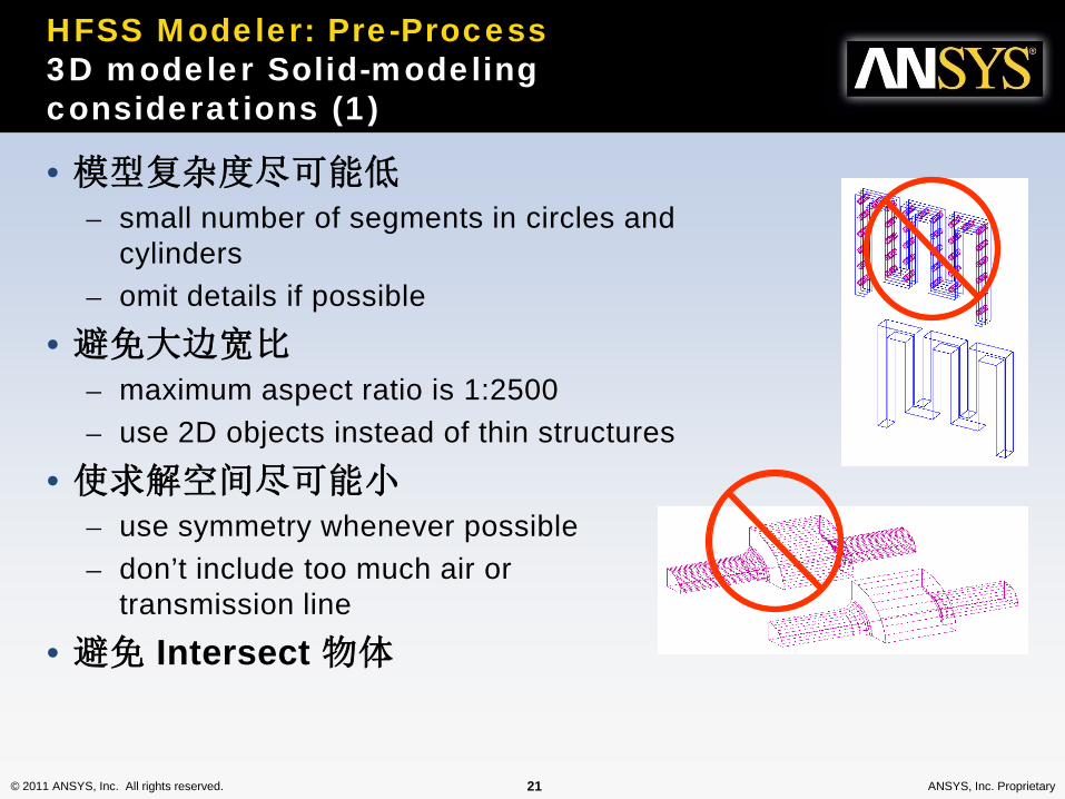
• 模型复杂度尽可能低– small number of segments in circles and
cylinders– omit details if possible
• 避免大边宽比– maximum aspect ratio is 1:2500– use 2D objects instead of thin structures
• 使求解空间尽可能小– use symmetry whenever possible– don’t include too much air or
transmission line
• 避免 Intersect 物体
HFSS Modeler: Pre-Process3D modeler Solid-modeling considerations (1)

© 2011 ANSYS, Inc. All rights reserved. 22 ANSYS, Inc. Proprietary
HFSS Modeler: Pre-ProcessSolid-Modeling Considerations (2)
• Few segments around circles and cylinders
• Thin metal patch is 2D object (aspect ratio!)
• No overlapping objects (inner conductor is two objects because it goes through two dielectrics)

© 2011 ANSYS, Inc. All rights reserved. 23 ANSYS, Inc. Proprietary
HFSS Modeler: Pre-ProcessSolid-Modeling Considerations (3)
• Some transmission line between port and antenna (length line not much smaller than cross section port)
• Some air between antenna and radiation boundary (λ/4)

© 2011 ANSYS, Inc. All rights reserved. 24 ANSYS, Inc. Proprietary
• Use trace thickness only when needed (when edge coupling is important or metal thickness < δ)
HFSS Modeler: Pre-ProcessPreconditioning Geometry
Use thickness
Don’t use thickness
© 2011 ANSYS, Inc. All rights reserved. 25 ANSYS, Inc. Proprietary
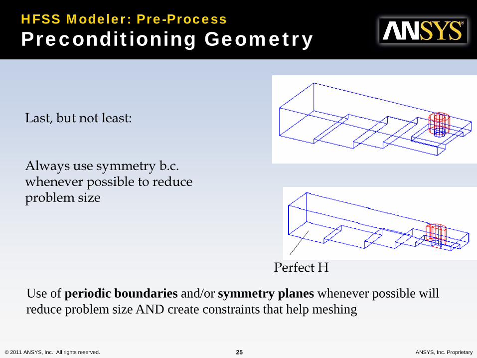
Last, but not least:
Always use symmetry b.c. whenever possible to reduce problem size
Perfect H
Use of periodic boundaries and/or symmetry planes whenever possible will reduce problem size AND create constraints that help meshing
HFSS Modeler: Pre-ProcessPreconditioning Geometry
© 2011 ANSYS, Inc. All rights reserved. 26 ANSYS, Inc. Proprietary
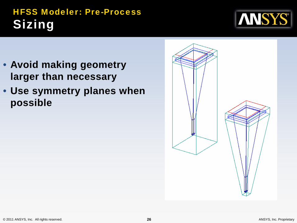
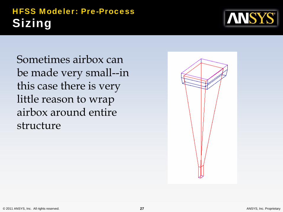
HFSS Modeler: Pre-ProcessSizing
• Avoid making geometry larger than necessary
• Use symmetry planes when possible
© 2011 ANSYS, Inc. All rights reserved. 27 ANSYS, Inc. Proprietary
Sometimes airbox can be made very small--in this case there is very little reason to wrap airbox around entire structure
HFSS Modeler: Pre-ProcessSizing

© 2011 ANSYS, Inc. All rights reserved. 29 ANSYS, Inc. Proprietary
HFSS Modeler: Pre-ProcessVirtual Objects
• Virtual Objects Are Dummy 2D or 3D Objects that do not change the physics of the model (e.g. an air object inside another air object).
• They Are Used to Assist in Getting a Higher-Quality Mesh
© 2011 ANSYS, Inc. All rights reserved. 30 ANSYS, Inc. Proprietary
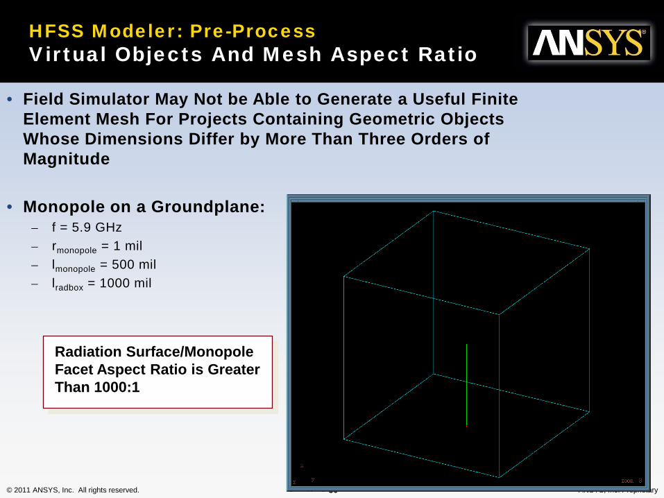
HFSS Modeler: Pre-ProcessVirtual Objects And Mesh Aspect Ratio
• Field Simulator May Not be Able to Generate a Useful Finite Element Mesh For Projects Containing Geometric Objects Whose Dimensions Differ by More Than Three Orders of Magnitude
• Monopole on a Groundplane:– f = 5.9 GHz– rmonopole = 1 mil– lmonopole = 500 mil– lradbox = 1000 mil
Radiation Surface/MonopoleFacet Aspect Ratio is GreaterThan 1000:1

© 2011 ANSYS, Inc. All rights reserved. 31 ANSYS, Inc. Proprietary
HFSS Modeler: Pre-Process Inclusion of a Virtual Object Compensates For High Aspect Ratio
Use The Plot/MeshFeature in the FieldsPost Processor

© 2011 ANSYS, Inc. All rights reserved. 32 ANSYS, Inc. Proprietary
HFSS Modeler: Pre-Process Inclusion of a Virtual Object Compensates For High Aspect Ratio
© 2011 ANSYS, Inc. All rights reserved. 33 ANSYS, Inc. Proprietary
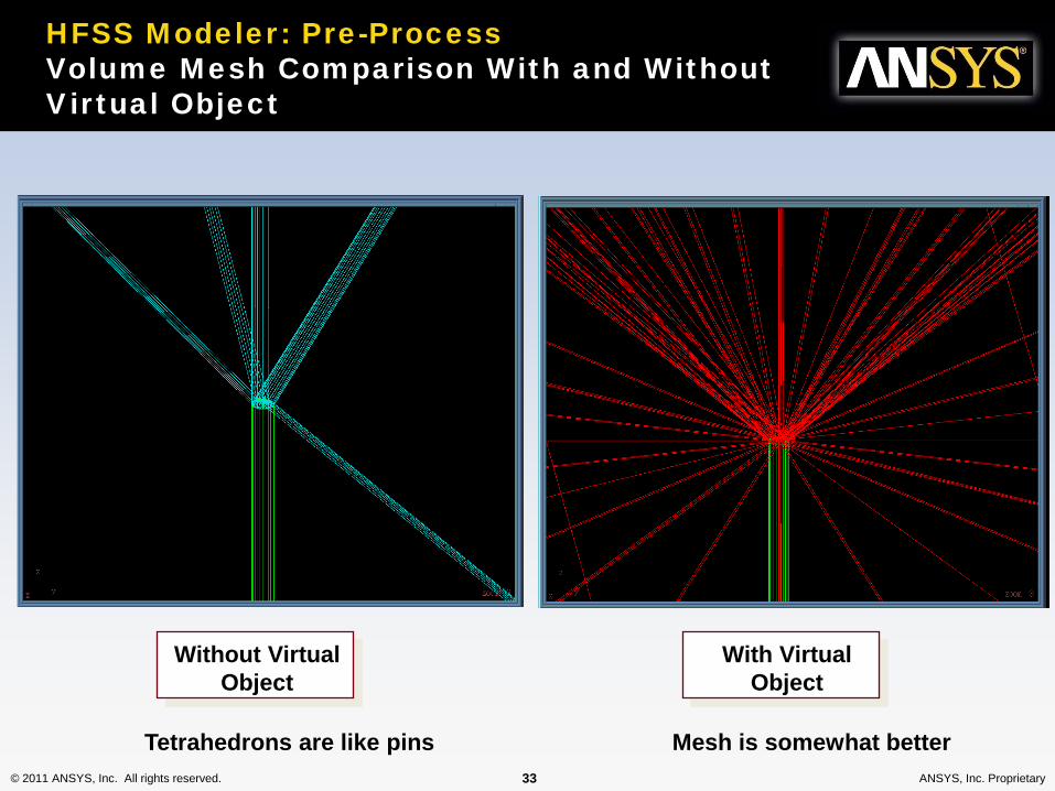
HFSS Modeler: Pre-Process Volume Mesh Comparison With and Without Virtual Object
Without VirtualObject
With VirtualObject
Mesh is somewhat betterTetrahedrons are like pins

© 2011 ANSYS, Inc. All rights reserved. 34 ANSYS, Inc. Proprietary
(Overlap between two cylinders)
Overlapping Geometry
• 定义: – When an object occupies volume in multiple 3D objects. This
does not apply to sheet objects• 解决方法:
– Set Material Override• Menu item: HFSS > Design Settings
© 2011 ANSYS, Inc. All rights reserved. 39 ANSYS, Inc. Proprietary

微波 EDA 网视频培训教程推荐
微波 EDA 网(www.mweda.com)成立于 2004 年底,并于翌年与易迪拓培训合并,专注于
微波、射频和硬件工程师的培养,现已发展成为国内最大的微波射频和无线通信人才培养基地。
先后与人民邮电出版社、电子工业出版社合作出版了多本专业图书,成功推出了多套微波射频
经典培训课程和 ADS、HFSS 等软件的使用培训课程,广受工程技术学员的好评,帮助数万名
工程师提升了专业技术能力。客户遍布中兴通讯、研通高频、埃威航电、国人通信等多家国内
知名公司,以及台湾工业技术研究院、永业科技、全一电子等多家台湾地区企业。
HFSS 中文视频培训课程套装
国内最全面和专业的 HFSS 培训教程套装,包含 5 套视频教程
和 2 本教材,李明洋老师讲解;结合最新工程案例,视频操作
演示,让 HFSS 学习不再难。购买套装更可超值赠送 3 个月免
费学习答疑,让您花最少的成本,以最快的速度自学掌握
HFSS… 【点击浏览详情】
两周学会 HFSS —— 中文视频教程
李明洋主讲,视频同步操作演示,直观易学。课程从零讲起,通过两周的课程学习,可以
帮助您快速入门、自学掌握 HFSS,真正做到让 HFSS 学习不再难…【点击浏览详情】
HFSS 微波器件仿真分析实例 —— 中文视频教程
HFSS 进阶培训课程,中文视频,通过十个 HFSS 仿真设计工程应用实例,带您更深入学
习 HFSS 的实际应用,掌握 HFSS 高级设置和应用技巧…【点击浏览详情】
HFSS 天线设计入门 —— 中文视频教程
HFSS 是天线设计的王者,该教程全面解析了天线的基础知识、HFSS 天线设计流程和详
细操作设置,让 HFSS 天线设计不再难…【点击浏览详情】
PCB 天线设计和 HFSS 仿真分析实例 —— 中文视频教程
详细讲解了 PCB 天线的工作原理和设计方法、如何使用 HFSS 来设计分析 PCB 天线,
以及如何借助于 Smith 圆图工作来调试天线的匹配电路,改善天线性能…【点击浏览详情】
了解详情,请查看微波 EDA 网(www.mweda.com/eda/hfss.html)

`
微波射频测量仪器培训课程套装合集
搞射频微波,不会仪器操作怎么行!矢量网络分析仪、频谱仪、
示波器、信号源是微波射频工程师最常用的测量仪器。该培训
套装集合了直观的视频培训教程和详尽的图书教材,旨在帮助
您快速熟悉和精通矢网、频谱仪、示波器等仪器的操作…【点
击浏览详情】
Agilent ADS 学习培训课程套装
国内最全面和权威的ADS 培训教程,详细讲解了ADS 在微波射频电路、
通信系统和电磁仿真设计方面的应用。课程是由具有多年 ADS 使用经
验的资深专家讲解,结合工程实例,直观易学;能让您在最短的时间内
学会 ADS,并把 ADS 真正应用到研发工作中去… 【点击浏览详情】
我们的课程优势:
※ 成立于 2004 年,一直专注于射频工程师的培养,行业经验丰富,更了解您的需求
※ 视频课程、既能达到现场培训的效果,又能免除您舟车劳顿的辛苦,学习工作两不误
※ 经验丰富的一线资深专家主讲,结合实际工程案例,直观、实用、易学
※ 更多实用课程,欢迎登陆我们的官方网站 http://www.mweda.com,或者登陆我们的官
方淘宝店 http://shop36920890.taobao.com/
专注于微波、射频、硬件工程师的培养,
网址:http://www.mweda.com
Q Q:625774272