hit-re 500 v3 injection mortar eta-16/0143...english deutsch francais italiano polski centre...
TRANSCRIPT

HILTI HIT-RE 500 V3 INJECTION MORTAR ETA-16/0143 (12.07.2017)
2-4850-9698-144146-192194-242
EnglishDeutschFrancaisItalianoPolski

Centre Scientifique et
Technique du Bâtiment 84 avenue Jean Jaurès CHAMPS-SUR-MARNE F-77447 Marne-la-Vallée Cedex 2 Tél. : (33) 01 64 68 82 82 Fax : (33) 01 60 05 70 37
Member of
www.eota.eu
European Technical Assessment
ETA-16/0143 du 12/07/2017
English translation prepared by CSTB - Original version in French language
General Part
Nom commercial Trade name
Injection system Hilti HIT-RE 500 V3
Famille de produit Product family
Cheville à scellement avec tige filetée, fers à béton, douille taraudée et cheville de traction Hilti HZA pour ancrage dans le béton fissuré.
Bonded fastener with threaded rods, rebar, internally sleeve and Hilti tension anchor HZA for use in concrete.
Titulaire Manufacturer
Hilti Corporation Feldkircherstrasse 100 FL-9494 Schaan Principality of Liechtenstein
Usine de fabrication Manufacturing plants
Hilti Plant
Cette evaluation contient: This Assessment contains
477 pages incluant 44 pages d’annexes qui font partie intégrante de cette évaluation 477 pages including 44 pages of annexes which form an integral part of this assessment
Base de l‘ETE Basis of ETA
ETAG 001, Version April 2013, utilisée en tant que EAD
ETAG 001, Edition April 2013 used as EAD
Cette évaluation remplace: This Assessment replaces
ETE-16/0143 du 28/07/2016 ETA-16/0143 dated 28/07/2016
Translations of this European Technical Assessment in other languages shall fully correspond to the original issued document and should be identified as such. Communication of this European Technical Assessment, including transmission by electronic means, shall be in full. However, partial reproduction may be made, with the written consent of the issuing Technical Assessment Body. Any partial reproduction has to be identified as such..

European technical assessment ETA-1 6 / 0 1 4 3
English translation prepared by CSTB
Page 2 sur 47 | 1 2 / 0 7 / 2 0 1 7
Specific Part
1 Technical description of the product
The Injection system Hilti HIT-RE 500 V3 is a bonded fastener consisting of a foil pack with injection mortar Hilti HIT-RE 500 V3 and a steel element.
a threaded rod Hilti HIT-V, Hilti meter rod AM 8.8 or a commercial threaded rod with washer and hexagon nut in the range of M8 to M30
a rebar in the range of 8 to 32
a Hilti Tension Anchor HZA in the range of M12 to M27 or HZA-R in the range of M12 to M24.
an internal threaded sleeve HIS-(R)N in the range M8 to M20
The steel element is placed into a drilled hole filled with injection mortar and is anchored via the bond between metal part, injection mortar and concrete.
The illustration and the description of the product are given in Annexes A.
2 Specification of the intended use
The performances given in Section 3 are only valid if the fastener is used in compliance with the specifications and conditions given in Annexes B.
The provisions made in this European technical assessment are based on an assumed working life of the fastener of 50 years. The indications given on the working life cannot be interpreted as a guarantee given by the producer, but are to be regarded only as a means for choosing the right products in relation to the expected economically reasonable working life of the works.
3 Performance of the product
3.1 Mechanical resistance and stability (BWR 1)
Essential characteristic Performance
Characteristic resistance for static and quasi static loads, Displacements
See Annex C1 to C16
Characteristic resistance for seismic performance category C1, Displacements
See Annex C17 to C20
Characteristic resistance for seismic performance category C2, Displacements
See Annex C21
3.2 Safety in case of fire (BWR 2)
Essential characteristic Performance
Reaction to fire Anchorages satisfy requirements for Class A1
Resistance to fire No performance assessed
3.3 Hygiene, health and the environment (BWR 3)
Regarding dangerous substances contained in this European technical approval, there may be requirements applicable to the products falling within its scope (e.g. transposed European legislation and national laws, regulations and administrative provisions). In order to meet the provisions of the Construction Products Directive, these requirements need also to be complied with, when and where they apply.

European technical assessment ETA-1 6 / 0 1 4 3
English translation prepared by CSTB
Page 3 sur 47 | 1 2 / 0 7 / 2 0 1 7
3.4 Safety in use (BWR 4)
For Basic requirement Safety in use the same criteria are valid as for Basic Requirement Mechanical resistance and stability.
3.5 Protection against noise (BWR 5)
Not relevant.
3.6 Energy economy and heat retention (BWR 6)
Not relevant.
3.7 Sustainable use of natural resources (BWR 7)
For the sustainable use of natural resources no performance was determined for this product.
3.8 General aspects relating to fitness for use
Durability and Serviceability are only ensured if the specifications of intended use according to Annex B1 are kept.
4 Assessment and verification of constancy of performance (AVCP)
According to the Decision 96/582/EC of the European Commission1, as amended, the system of assessment and verification of constancy of performance (see Annex V to Regulation (EU) No 305/2011) given in the following table apply.
Product Intended use Level or class System
Metal fasteners for use in concrete
For fixing and/or supporting to concrete, structural elements (which contributes to the stability of the works) or heavy units
― 1
5 Technical details necessary for the implementation of the AVCP system
Technical details necessary for the implementation of the Assessment and verification of constancy of performance (AVCP) system are laid down in the control plan deposited at Centre Scientifique et Technique du Bâtiment.
The manufacturer shall, on the basis of a contract, involve a notified body approved in the field of fasteners for issuing the certificate of conformity CE based on the control plan.
The original French version is signed by
Charles Baloche
Technical Director
1 Official Journal of the European Communities L 254 of 08.10.1996

European technical assessment ETA-1 6 / 0 1 4 3 English translation prepared by CSTB
Page 4 sur 47 | 1 2 / 0 7 / 2 0 1 7
Injection system Hilti HIT-RE 500 V3
Annex A1 Product Installed condition
Installed condition
Figure A1:
Threaded rod, HIT-V-…, AM…8.8 …
Figure A2:
Threaded rod, HIT-V-…, AM…8.8, with Hilti Filling Set…
Figure A3:
Internally threaded sleeve HIS-(R)N
tfix
d0
Marking of the embedment depth
h
h0 = hef
tfix
hs
df
h
h0 = hef
d0
Marking of the embedment depth

European technical assessment ETA-1 6 / 0 1 4 3 English translation prepared by CSTB
Page 5 sur 47 | 1 2 / 0 7 / 2 0 1 7
Injection system Hilti HIT-RE 500 V3
Annex A2 Product Installed condition
Figure A4:
Reinforcing bar (rebar)
Marking of the embedment depth
h0 = hef
h
d0

European technical assessment ETA-1 6 / 0 1 4 3 English translation prepared by CSTB
Page 6 sur 47 | 1 2 / 0 7 / 2 0 1 7
Injection system Hilti HIT-RE 500 V3
Annex A3 Product Injection mortar / Static mixer / Steel elements
Product description: Injection mortar and steel elements
Injection mortar Hilti HIT-RE 500 V3: epoxy resin system with aggregate
330 ml, 500 ml and 1400 ml
Marking: HILTI HIT Product name Production time and line Expiry date mm/yyyy
Product name: “Hilti HIT-RE 500 V3”
Static mixer Hilti HIT-RE-M
Steel elements
Threaded rod and HIT-V-...: M8 to M30 washer nut
Hilti meter rod AM 8.8, electroplated zinc coated M8 to M30, 1m to 3m
Commercial standard threaded rod with:
Materials and mechanical properties according to Table A1. Inspection certificate 3.1 according to EN 10204:2004. The document shall be stored. Marking of embedment depth.
Internally threaded sleeve HIS-(R)N: M8 to M20
Hilti Tension Anchor HZA: M12 to M27 and HZA-R: M12 to M24
Reinforcing bar (rebar): 8 to 32
Materials and mechanical properties according to Table A1. Dimensions according to Annex B6
HIL
TI
HIS
...

European technical assessment ETA-1 6 / 0 1 4 3 English translation prepared by CSTB
Page 7 sur 47 | 1 2 / 0 7 / 2 0 1 7
Injection system Hilti HIT-RE 500 V3
Annex A4 Product Injection mortar / Static mixer / Steel elements
Hilti Filling Set to fill the annular gap between anchor and fixture
Sealing washer Spherical washer
Filling Set M16 M20 M24
Diameter of sealing washer dvs [mm] 56 60 70
Thickness of sealing washer hvs [mm] 6

European technical assessment ETA-1 6 / 0 1 4 3 English translation prepared by CSTB
Page 8 sur 47 | 1 2 / 0 7 / 2 0 1 7
Injection system Hilti HIT-RE 500 V3
Annex A5 Product description Materials
Table A1: Materials
Designation Material
Reinforcing bars (rebars)
Rebar EN 1992-1-1:2004 and AC:2010, Annex C
Bars and de-coiled rods class B or C with fyk and k according to NDP or NCL of EN 1992-1-1/NA:2013 fuk = ftk = k ∙ fyk
Metal parts made of zinc coated steel
Threaded rod, HIT-V-5.8 (F)
Strength class 5.8, fuk = 500 N/mm², fyk = 400 N/mm² Elongation at fracture (l0 = 5d) > 8% ductile
Electroplated zinc coated 5 m, (F) hot dip galvanized 45 m
Threaded rod, HIT-V-8.8 (F)
Strength class 8.8, fuk = 800 N/mm², fyk = 640 N/mm² Elongation at fracture (l0 = 5d) > 12% ductile
Electroplated zinc coated 5 m, Vmax
Hilti Meter rod, AM 8.8 (HDG)
Strength class 8.8, fuk = 800 N/mm², fyk = 640 N/mm² Elongation at fracture (l0 = 5d) > 12% ductile,
Electroplated zinc coated 5 m, (HDG) hot dip galvanized 45 m
Hilti tension anchor HZA
Round steel with threaded part: electroplated zinc coated 5 m Rebar: Bars class B according to NDP or NCL of EN 1992-1-1/NA:2013
Internally threaded sleeve HIS-N
Electroplated zinc coated 5 m
Washer Electroplated zinc coated 5 m, hot dip galvanized 45 m
Nut Strength class of nut adapted to strength class of threaded rod.
Electroplated zinc coated 5 m, hot dip galvanized 45 m
Metal parts made of stainless steel
Threaded rod, HIT-V-R
For ≤ M24: strength class 70, fuk = 700 N/mm², fyk = 450 N/mm² For > M24: strength class 50, fuk = 500 N/mm², fyk = 210 N/mm² Elongation at fracture (l0 = 5d) > 8% ductile Stainless steel 1.4401, 1.4404, 1.4578, 1.4571, 1.4439, 1.4362 EN 10088-1:2014
Hilti tension anchor HZA-R
Round steel with threaded part: Stainless steel 1.4404, 1.4362, 1.4571 EN 10088-1:2014 Rebar: Bars class B according to NDP or NCL of EN 1992-1-1/NA:2013
Internally threaded sleeve HIS-RN
Stainless steel 1.4401, 1.4571 EN 10088-1:2014
Washer Stainless steel 1.4401, 1.4404, 1.4578, 1.4571, 1.4439, 1.4362 EN 10088-1:2014
Nut Strength class of nut adapted to strength class of threaded rod. Stainless steel 1.4401, 1.4404, 1.4578, 1.4571, 1.4439, 1.4362 EN 10088-1:2014
Metal parts made of high corrosion resistant steel
Threaded rod, HIT-V-HCR
For ≤ M20: fuk = 800 N/mm², fyk = 640 N/mm² For > M20: fuk = 700 N/mm², fyk = 400 N/mm²,
Elongation at fracture (l0 = 5d) > 8% ductile High corrosion resistant steel 1.4529, 1.4565 EN 10088-1:2014
Washer High corrosion resistant steel 1.4529, 1.4565 EN 10088-1:2014
Nut Strength class of nut adapted to strength class of threaded rod. High corrosion resistant steel 1.4529, 1.4565 EN 10088-1:2014

European technical assessment ETA-1 6 / 0 1 4 3 English translation prepared by CSTB
Page 9 sur 47 | 1 2 / 0 7 / 2 0 1 7
Injection system Hilti HIT-RE 500 V3
Annex A6 Product description Materials
Table A2: Materials of Hilti seismic filling set
metal part of zinc coated steel
5.1 Hilti Filling Set (F)
Filling washer: Electroplated zinc coated 5 m, (F) hot dip galvanized 45 m
Spherical washer: Electroplated zinc coated 5 m, (F) hot dip galvanized 45 m
5.2 Lock nut: Electroplated zinc coated 5 m, (F) hot dip galvanized 45 m

European technical assessment ETA-1 6 / 0 1 4 3 English translation prepared by CSTB
Page 10 sur 47 | 1 2 / 0 7 / 2 0 1 7
Injection system Hilti HIT-RE 500 V3
Annex B1 Intended use
Specifications
Specifications of intended use
Anchorages subject to:
Static and quasi static loading. Seismic performance category C1 Seismic performance category C2 (HIT-V , HIT-V-F, AM, AM-HDG grade 8.8 and commercial standard
rod grade 8.8 electroplated zinc coated only, with hammer drilling and hammer drilling with Hilti hollow drill bit TE-CD, TE-YD).
Base material:
Reinforced or unreinforced normal weight concrete according to EN 206:2013. Strength classes C20/25 to C50/60 according to EN 206:2013. Cracked and non-cracked concrete. Flooded holes for non cracked concrete only
Temperature in the base material:
At installation -5 °C to +40 °C
In-service Temperature range I: -40 °C to +40 °C (max. long term temperature +24 °C and max. short term temperature +40 °C) Temperature range II: -40 °C to +70 °C (max. long term temperature +43 °C and max. short term temperature +70 °C)
Use conditions (Environmental conditions):
Structures subject to dry internal conditions (zinc coated steel, stainless steel or high corrosion resistant steel).
Structures subject to external atmospheric exposure (including industrial and marine environment) and to permanently damp internal conditions, if no particular aggressive conditions exist (stainless steel or high corrosion resistant steel).
Structures subject to external atmospheric exposure and to permanently damp internal conditions, if other particular aggressive conditions exist (high corrosion resistant steel). Note: Particular aggressive conditions are e.g. permanent, alternating immersion in seawater or the splash zone of seawater, chloride atmosphere of indoor swimming pools or atmosphere with extreme chemical pollution (e.g. in desulphurization plants or road tunnels where de-icing products are used).
Design:
Anchorages are designed under the responsibility of an engineer experienced in anchorages and concrete work.
Verifiable calculation notes and drawings are prepared taking account of the loads to be anchored. The position of the anchor is indicated on the design drawings (e. g. position of the anchor relative to reinforcement or to supports, etc.).
Anchorages under static or quasi-static loading are designed in accordance with: “EOTA Technical Report TR 029, 09/2010” “CEN/TS 1992-4:2009”
Anchorages under seismic actions (cracked concrete) are designed in accordance with: “EOTA Technical Report TR 045, 02/2013” Anchorages shall be positioned outside of critical regions (e.g. plastic hinges) of the concrete structure. Fastenings in stand-off installation or with a grout layer under seismic action are not covered in this European technical assessment (ETA).

European technical assessment ETA-1 6 / 0 1 4 3 English translation prepared by CSTB
Page 11 sur 47 | 1 2 / 0 7 / 2 0 1 7
Injection system Hilti HIT-RE 500 V3
Annex B2 Intended use
Specifications
Installation:
Use category: dry or wet concrete (not in flooded holes): for all drilling techniques dry or wet concrete or installation in flooded holes: for hammer drilling only, for non-cracked
concrete only Drilling technique:
hammer drilling, hammer drilling with Hilti hollow drill bit TE-CD, TE-YD, diamond coring, diamond coring with roughening with Hilti roughening tool TE-YRT.
Overhead installation is admissible. Anchor installation carried out by appropriately qualified personnel and under the supervision of the
person responsible for technical matters of the site.

European technical assessment ETA-1 6 / 0 1 4 3 English translation prepared by CSTB
Page 12 sur 47 | 1 2 / 0 7 / 2 0 1 7
Injection system Hilti HIT-RE 500 V3
Annex B3 Intended use
Installation parameters
Table B1: Installation parameters of threaded rod and HIT-V and AM
1) Parameter for design according to “EOTA Technical Report TR 029”. 2) Parameter for design according to “CEN/TS 1992-4:2009”. 3) For larger clearance hole see “TR 029 section 1.1”.
HIT-V-…
AM…8.8
Threaded rod, HIT-V-…, AM…8.8 M8 M10 M12 M16 M20 M24 M27 M30
Diameter of element d1) = dnom2) [mm] 8 10 12 16 20 24 27 30
Nominal diameter of drill bit d0 [mm] 10 12 14 18 22 28 30 35
Threaded rod, HIT-V-...: Effective embedment depth and drill hole depth
hef = h0 [mm] 60 to
160
60 to
200
70 to
240
80 to
320
90 to
400
96 to
480
108 to
540
120 to
600
Maximum diameter of clearance hole in the fixture 3) df [mm] 9 12 14 18 22 26 30 33
Thickness of Hilti filling set hfs [mm] - - - 11 13 15 - -
Effective fixture thickness with Hilti filling set
tfix,eff [mm] tfix,eff =tfix-hfs
Minimum thickness of concrete member
hmin [mm] hef + 30
≥ 100 mm hef + 2d0
Maximum torque moment Tmax [Nm] 10 20 40 80 150 200 270 300
Minimum spacing smin [mm] 40 50 60 75 90 115 120 140
Minimum edge distance cmin [mm] 40 45 45 50 55 60 75 80
d
Marking:
5.8 - l = HIT-V-5.8 M…x l
5.8F - l = HIT-V-5.8F M…x l
8.8 - l = HIT-V-8.8 M…x l
8.8F - l = HIT-V-8.8F M…x l
R - l = HIT-V-R M ...x l
HCR - l = HIT-V-HCR M ...x l
l

European technical assessment ETA-1 6 / 0 1 4 3 English translation prepared by CSTB
Page 13 sur 47 | 1 2 / 0 7 / 2 0 1 7
Injection system Hilti HIT-RE 500 V3
Annex B4 Intended use Installation parameters
Table B2: Installation parameters of internally threaded sleeve HIS-(R)N
1) Parameter for design according to “EOTA Technical Report TR 029”. 2) Parameter for design according to “CEN/TS 1992-4:2009”. 3) For larger clearance hole see “TR 029 section 1.1”.
Internally threaded sleeve HIS-(R)N…
Internally threaded sleeve HIS-(R)N M8 M10 M12 M16 M20
Outer diameter of sleeve d1) = dnom2) [mm] 12,5 16,5 20,5 25,4 27,6
Nominal diameter of drill bit d0 [mm] 14 18 22 28 32
Effective embedment depth and drill hole depth
hef = h0 [mm] 90 110 125 170 205
Maximum diameter of clearance hole in the fixture 3) df [mm] 9 12 14 18 22
Minimum thickness of concrete member
hmin [mm] 120 150 170 230 270
Maximum torque moment Tmax [Nm] 10 20 40 80 150
Thread engagement length min-max
hs [mm] 8-20 10-25 12-30 16-40 20-50
Minimum spacing smin [mm] 60 75 90 115 130
Minimum edge distance cmin [mm] 40 45 55 65 90 H
ILT
I H
IS..
.
hef
d
Marking: Identifying mark - HILTI and embossing “HIS-N” (for zinc coated steel) embossing “HIS-RN” (for stainless steel)

European technical assessment ETA-1 6 / 0 1 4 3 English translation prepared by CSTB
Page 14 sur 47 | 1 2 / 0 7 / 2 0 1 7
Injection system Hilti HIT-RE 500 V3
Annex B5 Intended use Installation parameters
Table B3: Installation parameters of Hilti tension anchor HZA-R
1) For larger clearance hole see “TR 029 section 1.1”.
Hilti Tension Anchor HZA-R
Hilti tension anchor HZA-R M12 M16 M20 M24
Rebar diameter [mm] 12 16 20 25
Nominal embedment depth and drill hole depth hnom = h0 [mm] 170 to
240 180 to
320 190 to
400 200 to
500
Effective embedment depth (hef = hnom – le) hef [mm] hnom – 100
Length of smooth shaft le [mm] 100
Nominal diameter of drill bit d0 [mm] 16 20 25 32
Maximum diameter of clearance hole in the fixture 1)
df [mm] 14 18 22 26
Maximum torque moment Tmax [Nm] 40 80 150 200
Minimum thickness of concrete member hmin [mm] hnom + 2·d0
Minimum spacing smin [mm] 65 80 100 130
Minimum edge distance cmin [mm] 45 50 55 60
Marking: embossing “HZA-R” M .. / tfix
le tfix
hnom
HZA-R M
hef

European technical assessment ETA-1 6 / 0 1 4 3 English translation prepared by CSTB
Page 15 sur 47 | 1 2 / 0 7 / 2 0 1 7
Injection system Hilti HIT-RE 500 V3
Annex B6 Intended use
Installation parameters
Table B4: Installation parameters of Hilti tension anchor HZA
1) For larger clearance hole see “TR 029 section 1.1”.
Hilti tension anchor HZA M12 M16 M20 M24 M27
Rebar diameter [mm] 12 16 20 25 28
Nominal embedment depth and drill hole depth
hnom = h0 [mm] 90 to 240 100 to 320 110 to 400 120 to 500 140 to 560
Effective embedment depth (hef = hnom – le)
hef [mm] hnom – 20
Length of smooth shaft le [mm] 20
Nominal diameter of drill bit d0 [mm] 16 20 25 32 35
Maximum diameter of clearance hole in the fixture 1)
df [mm] 14 18 22 26 30
Maximum torque moment Tmax [Nm] 40 80 150 200 270
Minimum thickness of concrete member
hmin [mm] hnom + 2·d0
Minimum spacing smin [mm] 65 80 100 130 140
Minimum edge distance cmin [mm] 45 50 55 60 75

European technical assessment ETA-1 6 / 0 1 4 3 English translation prepared by CSTB
Page 16 sur 47 | 1 2 / 0 7 / 2 0 1 7
Injection system Hilti HIT-RE 500 V3
Annex B7 Intended use
Installation parameters
Table B5: Installation parameters of reinforcing bar (rebar)
1) Each of the two given values can be used.
Reinforcing bar (rebar)
For Rebar bolt
Minimum value of related rib area fR,min according to EN 1992-1-1:2004+AC:2010.
Rib height of the bar hrib shall be in the range 0,05· ≤ hrib ≤ 0,07·
(: Nominal diameter of the bar; hrib: Rib height of the bar).
Reinforcing bar (rebar) 8 10 12 14 16 20 25 28 30 32
Diameter [mm] 8 10 12 14 16 20 25 28 30 32
Effective embedment depth and drill hole depth
hef = h0
[mm] 60 to
160
60 to
200
70 to
240
75 to
280
80 to
320
90 to
400
100 to
500
112 to
560
120 to
600
128 to
640
Nominal diameter of drill bit
d0 [mm] 101) 121)
121)
141) 141) 161) 18 20 25
301)
321) 35 37 40
Minimum thickness of concrete member
hmin [mm] hef + 30
≥ 100 mm hef + 2·d0
Minimum spacing smin [mm] 40 50 60 70 80 100 125 140 150 160
Minimum edge distance cmin [mm] 40 45 45 50 50 65 70 75 80 80

European technical assessment ETA-1 6 / 0 1 4 3 English translation prepared by CSTB
Page 17 sur 47 | 1 2 / 0 7 / 2 0 1 7
Injection system Hilti HIT-RE 500 V3
Annex B8 Intended use
Maximum working time and minimum curing time
Table B6: Minimum curing time1)
1) The curing time data are valid for dry base material only. In wet base material the curing times must be doubled.
Temperature in the base material T
Maximum working time twork
Minimum curing time tcure
1)
-5 °C to -1 °C 2 hours 168 hours
0 °C to 4 °C 2 hours 48 hours
5 °C to 9 °C 2 hours 24 hours
10 °C to 14 °C 1,5 hours 16 hours
15 °C to 19 °C 1 hours 12 hours
20 °C to 24 °C 30 min 7 hours
25 °C to 29 °C 20 min 6 hours
30 °C to 34 °C 15 min 5 hours
35 °C to 39 °C 12 min 4,5 hours
40 °C 10 min 4 hours

European technical assessment ETA-1 6 / 0 1 4 3 English translation prepared by CSTB
Page 18 sur 47 | 1 2 / 0 7 / 2 0 1 7
Injection system Hilti HIT-RE 500 V3
Annex B9 Intended use
Cleaning and setting tools
Table B7: Parameters of cleaning and setting tools
1) To be used in combination with Hilti vacuum cleaner with suction volume ≥ 61 l/s (VC 20/40 –Y in corded mode only).
Cleaning alternatives
Compressed Air Cleaning (CAC):
air nozzle with an orifice opening of minimum 3,5 mm in diameter.
Automatic Cleaning (AC):
Cleaning is performed during drilling with Hilti TE-CD and TE-YD drilling system including vacuum cleaner.
Elements Drill and clean Installa-
tion
Threaded rod,
HIT-V-… AM…8.8
HIS-(R)N Rebar HZA(-R)
Hammer drilling Diamond coring
Brush Piston plug
Hollow drill bit TE-CD,
TE-YD
Roughen-ing tool TE-YRT
Size Name Size Size d0 [mm] d0 [mm] d0 [mm] d0 [mm] HIT-RB HIT-SZ
M8 - 8 - 10 - 10 - 10 -
M10 - 8, 10 - 12 - 12 - 12 12
M12 M8 10, 12 - 14 14 1) 14 - 14 14
- - 12 M12 16 16 16 - 16 16
M16 M10 14 - 18 18 18 18 18 18
- - 16 M16 20 20 20 20 20 20
M20 M12 - - 22 22 22 22 22 22
- - 20 M20 25 25 25 25 25 25
M24 M16 - - 28 28 28 28 28 28
M27 - - - 30 - 30 30 30 30
- M20 25 M24 32 32 32 32 32 32
M30 - 28 M27 35 35 35 35 35 35
- - 30 - 37 - 37 - 37 37
- - 32 - 40 - - - 40 40
- - 42 - 42 42

European technical assessment ETA-1 6 / 0 1 4 3 English translation prepared by CSTB
Page 19 sur 47 | 1 2 / 0 7 / 2 0 1 7
Injection system Hilti HIT-RE 500 V3
Annex B10 Intended use
Parameters for use of the Hilti Roughening tool TE-YRT
Table B8: Parameters for use of the Hilti roughening tool TE-YRT
Hilti roughening tool TE-YRT and wear gauge RTG
Associated components Installation
Diamond coring Roughening tool
TE-YRT Wear gauge
RTG… Minimum roughening time
troughen
d0 [mm] d0 [mm] size troughen [sec] = hef [mm] / 10
nominal measured
18 17,9 to 18,2 18 18
hef [mm] troughen [sec]
0 to 100 10
101 to 200 20
201 to 300 30
301 to 400 40
401 to 500 50
501 to 600 60
20 19,9 to 20,2 20 20
22 21,9 to 22,2 22 22
25 24,9 to 25,2 25 25
28 27,9 to 28,2 28 28
30 29,9 to 30,2 30 30
32 31,9 to 32,2 32 32
35 34,9 to 35,2 35 35
TE-YRT
RTG

European technical assessment ETA-1 6 / 0 1 4 3 English translation prepared by CSTB
Page 20 sur 47 | 1 2 / 0 7 / 2 0 1 7
Injection system Hilti HIT-RE 500 V3
Annex B11 Intended use
Installation instructions
Installation instruction
Hole drilling
a) Hammer drilling: For dry or wet concrete and installation in flooded holes (no sea water).
Drill hole to the required embedment depth with a hammer drill set in rotation-hammer mode using an appropriately sized carbide drill bit.
b) Hammer drilling with Hilti hollow drill bit TE-CD, TE-YD: For dry and wet concrete only.
Drill hole to the required embedment depth with an appropriately sized Hilti TE-CD or TE-YD hollow drill bit attached to Hilti vacuum cleaner VC 20/40 (-Y) (suction volume ≥ 57 l/s) with automatic cleaning of the filter activated. This drilling system removes the dust and cleans the bore hole during drilling when used in accordance with the user’s manual. When using TE-CD 14 refer to Table B7. After drilling is completed, proceed to the “injection preparation” step in the installation instruction.
c) Diamond coring: For dry and wet concrete only.
Diamond coring is permissible when suitable diamond core drilling machines and the corresponding core bits are used.
d) Diamond coring with roughening with Hilti roughening tool TE-YRT: For dry and wet concrete only.
Diamond coring is permissible when suitable diamond core drilling machines and the corresponding core bits are used. For the use in combination with Hilti roughening tool TE-YRT see parameters in Table B8. Before roughening water needs to be removed from the borehole. Check usability of the roughening tool with the wear gauge RTG. Roughen the borehole over the whole length to the required hef.

European technical assessment ETA-1 6 / 0 1 4 3 English translation prepared by CSTB
Page 21 sur 47 | 1 2 / 0 7 / 2 0 1 7
Injection system Hilti HIT-RE 500 V3
Annex B12 Intended use
Installation instructions
Drill hole cleaning: Just before setting an anchor, the drill hole must be free of dust and debris. Inadequate hole cleaning = poor load values.
Compressed Air Cleaning (CAC): For all drill hole diameters d0 and all drill hole depths h0.
Blow 2 times from the back of the hole (if needed with nozzle extension) over the whole length with oil-free compressed air (min. 6 bar at 6 m³/h) until return air stream is free of noticeable dust. For drill hole diameters ≥ 32 mm the compressor has to supply a minimum air flow of 140 m³/h.
Brush 2 times with the specified brush (see Table B7) by inserting the steel brush Hilti HIT-RB to the back of the hole (if needed with extension) in a twisting motion and removing it. The brush must produce natural resistance as it enters the drill hole (brush Ø ≥ drill hole Ø) - if not the brush is too small and must be replaced with the proper brush diameter.
Blow again with compressed air 2 times until return air stream is free of noticeable dust.

European technical assessment ETA-1 6 / 0 1 4 3 English translation prepared by CSTB
Page 22 sur 47 | 1 2 / 0 7 / 2 0 1 7
Injection system Hilti HIT-RE 500 V3
Annex B13 Intended use
Installation instructions
Cleaning of hammer drilled flooded holes and diamond cored holes: For all drill hole diameters d0 and all drill hole depths h0.
Flush 2 times by inserting a water hose (water-line pressure) to the back of the hole until water runs clear.
Brush 2 times with the specified brush (see Table B7) by inserting the steel brush Hilti HIT-RB to the back of the hole (if needed with extension) in a twisting motion and removing it. The brush must produce natural resistance as it enters the drill hole (brush Ø ≥ drill hole Ø) - if not the brush is too small and must be replaced with the proper brush diameter.
Flush 2 times by inserting a water hose (water-line pressure) to the back of the hole until water runs clear.
Blow 2 times from the back of the hole (if needed with nozzle extension) over the whole length with oil-free compressed air (min. 6 bar at 6 m³/h) until return air stream is free of noticeable dust and water. For drill hole diameters ≥ 32 mm the compressor has to supply a minimum air flow of 140 m³/h.
Brush 2 times with the specified brush size (brush Ø ≥ drill hole Ø, see Table B7) by inserting the steel brush Hilti HIT-RB to the back of the hole (if needed with extension) in a twisting motion and removing it. The brush must produce natural resistance as it enters the drill hole – if not the brush is too small and must be replaced with the proper brush diameter.
Blow again with compressed air 2 times until return air stream is free of noticeable dust and water.

European technical assessment ETA-1 6 / 0 1 4 3 English translation prepared by CSTB
Page 23 sur 47 | 1 2 / 0 7 / 2 0 1 7
Injection system Hilti HIT-RE 500 V3
Annex B14 Intended use
Installation instructions
Cleaning of diamond cored holes with roughening with Hilti roughening tool TE-YRT: For all drill hole diameters d0 and all drill hole depths h0.
Flush 2 times by inserting a water hose (water-line pressure) to the back of the hole until water runs clear.
Brush 2 times with the specified brush (see Table B7) by inserting the steel brush Hilti HIT-RB to the back of the hole (if needed with extension) in a twisting motion and removing it. The brush must produce natural resistance as it enters the drill hole (brush Ø ≥ drill hole Ø) - if not the brush is too small and must be replaced with the proper brush diameter.
Blow 2 times from the back of the hole (if needed with nozzle extension) over the whole length with oil-free compressed air (min. 6 bar at 6 m³/h) until return air stream is free of noticeable dust and water. For drill hole diameters ≥ 32 mm the compressor has to supply a minimum air flow of 140 m³/h.

European technical assessment ETA-1 6 / 0 1 4 3 English translation prepared by CSTB
Page 24 sur 47 | 1 2 / 0 7 / 2 0 1 7
Injection system Hilti HIT-RE 500 V3
Annex B15 Intended use
Installation instructions
Injection preparation
Tightly attach Hilti mixing nozzle HIT-RE-M to foil pack manifold. Do not modify the mixing nozzle. Observe the instruction for use of the dispenser. Check foil pack holder for proper function. Insert foil pack into foil pack holder and put holder into dispenser.
The foil pack opens automatically as dispensing is initiated. Depending on the size of the foil pack an initial amount of adhesive has to be discarded. Discarded quantities are: 3 strokes for 330 ml foil pack, 4 strokes for 500 ml foil pack, 65 ml for 1400 ml foil pack.
Inject adhesive from the back of the drill hole without forming air voids.
Inject the adhesive starting at the back of the hole, slowly withdrawing the mixer with each trigger pull. Fill approximately 2/3 of the drill hole to ensure that the annular gap between the anchor and the concrete is completely filled with adhesive along the embedment length.
After injection is completed, depressurize the dispenser by pressing the release trigger. This will prevent further adhesive discharge from the mixer.
Overhead installation and/or installation with embedment depth hef > 250 mm. For overhead installation the injection is only possible with the aid of extensions and piston plugs. Assemble HIT-RE-M mixer, extension(s) and appropriately sized piston plug (see Table B7). Insert piston plug to back of the hole and inject adhesive. During injection the piston plug will be naturally extruded out of the drill hole by the adhesive pressure.
Setting the element Just before setting an anchor, the drill hole must be free of dust and debris.
Before use, verify that the element is dry and free of oil and other contaminants. Mark and set element to the required embedment depth before working time twork has elapsed. The working time twork is given in Table B6.
For overhead installation use piston plugs and fix embedded parts with e.g. wedges.
Loading the anchor: After required curing time tcure (see Table B6) the anchor can be loaded. The applied installation torque shall not exceed the values Tmax given in Tables B1, B2, B3 and B4.

European technical assessment ETA-1 6 / 0 1 4 3 English translation prepared by CSTB
Page 25 sur 47 | 1 2 / 0 7 / 2 0 1 7
Injection system Hilti HIT-RE 500 V3
Annex B16 Intended use
Installation instructions
Installation of Filling Set
Use Hilti filling set with standard nut. Observe the correct orientation of filling washer and spherical washer.
The applied installation torque shall not exceed the values Tmax given in Erreur ! Source du renvoi introuvable.1 to Table B5.
Optional: Installation of lock nut. Tighten with a ¼ to ½ turn. (Not for size M24.)
Fill the annular gap between the anchor rod and fixture with 1-3 strokes of Hilti injection mortar HIT-RE 500 V3. Follow the installation instructions supplied with the HIT-RE 500 V3 foil pack.

European technical assessment ETA-1 6 / 0 1 4 3 English translation prepared by CSTB
Page 26 sur 47 | 1 2 / 0 7 / 2 0 1 7
Injection system Hilti HIT-RE 500 V3
Annex C1 Performances Characteristic resistance under tension load in concrete Design according to “EOTA Technical Report TR 029, 09/2010” or “CEN/TS 1992-4:2009”
Table C1: Characteristic resistance for threaded rods under tension load in concrete
Threaded rod, HIT-V-…, AM…8.8 M8 M10 M12 M16 M20 M24 M27 M30
Installation safety factor
Hammer drilling 21) = inst
2) [-] 1,0
Hammer drilling with Hilti hollow drill bit TE-CD or TE-YD
21) = inst
2) [-] - 1,0
Diamond coring 21) = inst
2) [-] 1,2 1,4
Diamond coring with roughening with Hilti roughening tool TE-YRT
21) = inst
2) [-] - 1,0
Hammer drilling in flooded holes 21) = inst
2) [-] 1,4
Steel failure threaded rods
Characteristic resistance NRk,s [kN] As · fuk
Partial safety factor Grade 5.8 Ms,N [-] 1,5
Partial safety factor Grade 8.8 Ms,N [-] 1,5
Partial safety factor HIT-V-R Ms,N [-] 1,87 2,86
Partial safety factor HIT-V-HCR Ms,N [-] 1,5 2,1
Combined pullout and concrete cone failure
Characteristic bond resistance in non-cracked concrete C20/25 in hammer drilled holes and hammer drilled holes with Hilti hollow drill bit TE-CD or TE-YD and diamond cored holes with roughening with Hilti roughening tool TE-YRT
Temperature range I: 40°C / 24°C Rk,ucr [N/mm2] 18 18 17 16 15 15 14 13
Temperature range II: 70°C / 43°C Rk,ucr [N/mm2] 14 13 13 12 12 11 10 10
Characteristic bond resistance in non-cracked concrete C20/25 in diamond cored holes.
Temperature range I: 40°C / 24°C Rk,ucr [N/mm2] 12 12 12 12 12 11 11 11
Temperature range II: 70°C / 43°C Rk,ucr [N/mm2] 9,5 9 9 9 9 8,5 8,5 8,5
Characteristic bond resistance in non-cracked concrete C20/25 in hammer drilled holes and installation in water-filled holes
Temperature range I: 40°C / 24°C Rk,ucr [N/mm2] 15 15 15 14 13 12 12 11
Temperature range II: 70°C / 43°C Rk,ucr [N/mm2] 12 11 11 10 10 9,5 9 8,5
Factor acc. to section 6.2.2.3 of CEN/TS 1992-4:2009 part 5
k82) [-] 10,1
Characteristic bond resistance in cracked concrete C20/25 in hammer drilled holes and hammer drilled holes with Hilti hollow drill bit TE-CD or TE-YD and diamond cored holes with roughening with Hilti roughening tool TE-YRT
Temperature range I: 40°C / 24°C Rk,cr [N/mm2] 6,5 7,5 8 8 8 8 8 8
Temperature range II: 70°C / 43°C Rk,cr [N/mm2] 5,5 6 6 6 6 6 6 6
Factor acc. to section 6.2.2.3 of CEN/TS 1992-4:2009 part 5
k82) [-] 7,2

European technical assessment ETA-1 6 / 0 1 4 3 English translation prepared by CSTB
Page 27 sur 47 | 1 2 / 0 7 / 2 0 1 7
Injection system Hilti HIT-RE 500 V3
Annex C2 Performances Characteristic resistance under tension load in concrete Design according to “EOTA Technical Report TR 029, 09/2010” or “CEN/TS 1992-4:2009”
Table C1: continued
Threaded rod, HIT-V-…, AM…8.8 M8 M10 M12 M16 M20 M24 M27 M30
Combined pullout and concrete cone failure (continued)
Increasing factors for
Rk in concrete
in hammer drilled holes and hammer drilled holes with Hilti hollow drill bit TE-CD or TE-YD and diamond cored holes
c
C30/37 1,04
C40/50 1,07
C50/60 1,09
in diamond cored holes with roughening with Hilti roughening tool TE-YRT
c C50/60 - 1,0
Concrete cone failure
Factor acc. to section 6.2.3 of CEN/TS 1992-4:2009 part 5
kucr2) [-] 10,1
kcr2) [-] 7,2
Edge distance ccr,N [mm] 1,5 hef
Spacing scr,N [mm] 3,0 hef
Splitting failure
Factor acc. to section 6.2.3 of CEN/TS 1992-4:2009 part 5
kucr2) [-] 10,1
kcr2) [-] 7,2
Edge distance ccr,sp [mm] for
h / hef ≥ 2,0 1,0 hef
2,0 > h / hef > 1,3 4,6 hef - 1,8 h
h / hef ≤ 1,3 2,26 hef
Spacing scr,sp [mm] 2 ccr,sp
1) Parameter for design according to EOTA Technical Report TR 029. 2) Parameter for design according to CEN/TS 1992-4:2009.
ccr,sp
h/hef
1,3
2,0
1,0 hef 2,26 hef

European technical assessment ETA-1 6 / 0 1 4 3 English translation prepared by CSTB
Page 28 sur 47 | 1 2 / 0 7 / 2 0 1 7
Injection system Hilti HIT-RE 500 V3
Annex C3 Performances Characteristic resistance under tension load in concrete Design according to “EOTA Technical Report TR 029, 09/2010” or “CEN/TS 1992-4:2009”
Table C2: Characteristic resistance for internally threaded sleeve HIS-(R)N under tension load in concrete
HIS-(R)N M8 M10 M12 M16 M20
Outer diameter of sleeve d1) = dnom2) [mm] 12,5 16,5 20,5 25,4 27,6
Installation safety factor
Hammer drilling 21) = inst
2) [-] 1,0
Hammer drilling with Hilti hollow drill bit TE-CD or TE-YD
21) = inst
2) [-] 1,0
Diamond coring 21) = inst
2) [-] 1,2 1,4
Diamond coring with roughening with Hilti roughening tool TE-YRT
21) = inst
2) [-] - 1,0
Hammer drilling in flooded holes 21) = inst
2) [-] 1,4
Steel failure
Characteristic resistance HIS-N with with screw grade 8.8
NRk,s [kN] 25 46 67 125 116
Partial safety factor Ms,N [-] 1,5
Characteristic resistance HIS-RN with with screw grade 70
NRk,s [kN] 26 41 59 110 166
Partial safety factor Ms,N [-] 1,87 2,4
Combined pullout and concrete cone failure3)
Characteristic bond resistance in non-cracked concrete C20/25 in hammer drilled holes and hammer drilled holes with Hilti hollow drill bit TE-CD or TE-YD and diamond cored holes with roughening with Hilti roughening tool TE-YRT
Temperature range I: 40°C / 24°C Rk,ucr [N/mm2] 13 13 13 13 13
Temperature range II: 70°C / 43°C Rk,ucr [N/mm2] 10 10 10 10 10
Characteristic bond resistance in non-cracked concrete C20/25 in diamond cored holes.
Temperature range I: 40°C / 24°C Rk,ucr [N/mm2] 8,5 8,5 9 9 9,5
Temperature range II: 70°C / 43°C Rk,ucr [N/mm2] 6,5 6,5 6,5 7 7
Characteristic bond resistance in non-cracked concrete C20/25 in hammer drilled holes and installation in water-filled holes
Temperature range I: 40°C / 24°C Rk,ucr [N/mm2] 11 11 11 11 11
Temperature range II: 70°C / 43°C Rk,ucr [N/mm2] 8,5 8,5 8,5 8,5 8,5
Factor acc. to section 6.2.2.3 of CEN/TS 1992-4:2009 part 5
k83) [-] 10,1

European technical assessment ETA-1 6 / 0 1 4 3 English translation prepared by CSTB
Page 29 sur 47 | 1 2 / 0 7 / 2 0 1 7
Injection system Hilti HIT-RE 500 V3
Annex C4 Performances Characteristic resistance under tension load in concrete Design according to “EOTA Technical Report TR 029, 09/2010” or “CEN/TS 1992-4:2009”
Table C2: continued
HIS-(R)N M8 M10 M12 M16 M20
Combined pullout and concrete cone failure3) (continued)
Characteristic bond resistance in cracked concrete C20/25 in hammer drilled holes and hammer drilled holes with Hilti hollow drill bit TE-CD or TE-YD and diamond cored holes with roughening with Hilti roughening tool TE-YRT
Temperature range I: 40°C / 24°C Rk,cr [N/mm2] 8,5 8,5 8,5 8,5 8,5
Temperature range II: 70°C / 43°C Rk,cr [N/mm2] 7 7 7 7 7
Factor acc. to section 6.2.2.3 of CEN/TS 1992-4:2009 part 5
k82) [-] 7,2
Increasing factors for
Rk in concrete
in hammer drilled holes and hammer drilled holes with Hilti hollow drill bit TE-CD or TE-YD and diamond cored holes
c
C30/37 1,04
C40/50 1,07
C50/60 1,09
in diamond cored holes with roughening with Hilti roughening tool TE-YRT
c C50/60 - 1,0
Concrete cone failure
Factor acc. to section 6.2.3 of CEN/TS 1992-4:2009 part 5
kucr2) [-] 10,1
kcr2) [-] 7,2
Edge distance ccr,N [mm] 1,5 hef
Spacing scr,N [mm] 3,0 hef
Splitting failure
Factor acc. to section 6.2.3 of CEN/TS 1992-4:2009 part 5
kucr2) [-] 10,1
kcr2) [-] 7,2
Edge distance ccr,sp [mm] for
h / hef ≥ 2,0 1,0 hef
2,0 > h / hef > 1,3 4,6 hef - 1,8 h
h / hef ≤ 1,3 2,26 hef
Spacing scr,sp [mm] 2 ccr,sp
1) Parameter for design according to EOTA Technical Report TR 029. 2) Parameter for design according to CEN/TS 1992-4:2009. 3) For design according to CEN/TS 1992-1:2009, the characteristic tension load values bond resistance may be
calculated from the characteristic bond resistance for combined pull-out and concrete cone failure according to:
NRk = Rk · (hef · d1 · ).
ccr,sp
h/hef
1,3
2,0
1,0 hef 2,26 hef

European technical assessment ETA-1 6 / 0 1 4 3 English translation prepared by CSTB
Page 30 sur 47 | 1 2 / 0 7 / 2 0 1 7
Injection system Hilti HIT-RE 500 V3
Annex C5 Performances Characteristic resistance under tension load in concrete Design according to “EOTA Technical Report TR 029, 09/2010” or “CEN/TS 1992-4:2009”
Table C3: Characteristic resistance for Hilti tension anchor HZA / HZA-R under tension load in concrete
HZA / HZA-R M12 M16 M20 M24 M27
Rebar diameter [mm] 12 16 20 25 28
Installation safety factor
Hammer drilling 21) = inst
2) [-] 1,0
Hammer drilling with Hilti hollow drill bit TE-CD or TE-YD
21) = inst
2) [-] 1,0
Diamond coring 21) = inst
2) [-] 1,2 1,4
Diamond coring with roughening with Hilti roughening tool TE-YRT
21) = inst
2) [-] - 1,0
Hammer drilling in flooded holes 21) = inst
2) [-] 1,4
Steel failure
Characteristic resistance HZA NRk,s [kN] 46 86 135 194 252
Characteristic resistance HZA-R NRk,s [kN] 62 111 173 249 -
Partial safety factor Ms,N [-] 1,4
Combined pullout and concrete cone failure
Characteristic bond resistance in non-cracked concrete C20/25 in hammer drilled holes and hammer drilled holes with Hilti hollow drill bit TE-CD or TE-YD and diamond cored holes with roughening with Hilti roughening tool TE-YRT
Temperature range I: 40°C / 24°C Rk,ucr [N/mm2] 14 14 14 13 13
Temperature range II: 70°C / 43°C Rk,ucr [N/mm2] 11 10 10 10 9,5
Characteristic bond resistance in non-cracked concrete C20/25 in diamond cored holes.
Temperature range I: 40°C / 24°C Rk,ucr [N/mm2] 9 9 9 9 9,5
Temperature range II: 70°C / 43°C Rk,ucr [N/mm2] 6,5 6,5 7 7 7
Characteristic bond resistance in non-cracked concrete C20/25 in hammer drilled holes and installation in water-filled holes
Temperature range I: 40°C / 24°C Rk,ucr [N/mm2] 12 12 12 11 11
Temperature range II: 70°C / 43°C Rk,ucr [N/mm2] 9 9 8,5 8,5 8,5
Factor acc. to section 6.2.2.3 of CEN/TS 1992-4:2009 part 5
k83) [-] 10,1

European technical assessment ETA-1 6 / 0 1 4 3 English translation prepared by CSTB
Page 31 sur 47 | 1 2 / 0 7 / 2 0 1 7
Injection system Hilti HIT-RE 500 V3
Annex C6 Performances Characteristic resistance under shear load in concrete Design according to “EOTA Technical Report TR 029, 09/2010” or “CEN/TS 1992-4:2009”
Table C3: continued
HZA / HZA-R M12 M16 M20 M24 M27
Rebar diameter [mm] 12 16 20 25 28
Combined pullout and concrete cone failure (continued)
Characteristic bond resistance in cracked concrete C20/25 in hammer drilled holes and hammer drilled holes with Hilti hollow drill bit TE-CD or TE-YD and diamond cored holes with roughening with Hilti roughening tool TE-YRT
Temperature range I: 40°C / 24°C Rk,cr [N/mm2] 9,5 9,5 10 10 11
Temperature range II: 70°C / 43°C Rk,cr [N/mm2] 8 8 8 8 8
Factor acc. to section 6.2.2.3 of CEN/TS 1992-4:2009 part 5
k82) [-] 7,2
Increasing
factors for Rk in concrete
in hammer drilled holes and hammer drilled holes with Hilti hollow drill bit TE-CD or TE-YD and diamond cored holes
c
C30/37 1,04
C40/50 1,07
C50/60 1,09
in diamond cored holes with roughening with Hilti roughening tool TE-YRT
c C50/60 1,0
Embedment depth for calculation of N0
Rk,p acc. eq. 5.2a (TR 029 §5.2.2.4 )
HZA hef [mm] hnom -20
HZA-R hef [mm] hnom -100 -
Concrete cone failure
Embedment depth for calculation of N0Rk,c
acc. eq. 5.3a (TR 029 §5.2.2.4 ) hef [mm] hnom
Factor acc. to section 6.2.3 of CEN/TS 1992-4:2009 part 5
kucr2) [-] 10,1
kcr2) [-] 7,2
Edge distance ccr,N [mm] 1,5 hef
Spacing scr,N [mm] 3,0 hef
Splitting failure
Factor acc. to section 6.2.3 of CEN/TS 1992-4:2009 part 5
kucr2) [-] 10,1
kcr2) [-] 7,2
Edge distance ccr,sp [mm] for
h / hef ≥ 2,0 1,0 hef
2,0 > h / hef > 1,3 4,6 hef - 1,8 h
h / hef ≤ 1,3 2,26 hef
Spacing scr,sp [mm] 2 ccr,sp
1) Parameter for design according to EOTA Technical Report TR 029. 2) Parameter for design according to CEN/TS 1992-4:2009.
ccr,sp
h/hef
1,3
2,0
1,0 hef 2,26 hef

European technical assessment ETA-1 6 / 0 1 4 3 English translation prepared by CSTB
Page 32 sur 47 | 1 2 / 0 7 / 2 0 1 7
Injection system Hilti HIT-RE 500 V3
Annex C7 Performances Characteristic resistance under shear load in concrete Design according to “EOTA Technical Report TR 029, 09/2010” or “CEN/TS 1992-4:2009”
Table C4: Characteristic resistance for reinforcing bars (rebars) under tension load in concrete
Reinforcing bar (rebar) 8 10 12 14 16 20 25 28 30 32
Installation safety factor
Hammer drilling 21) = inst
2) [-] 1,0
Hammer drilling with Hilti hollow drill bit TE-CD or TE-YD
21) = inst
2) [-] - 1,0 -
Diamond coring 21) = inst
2) [-] 1,2 1,4
Diamond coring with roughening with Hilti roughening tool TE-YRT
21) = inst
2) [-] - 1,0 -
Hammer drilling in flooded holes 21) = inst
2) [-] 1,4
Steel failure rebars
Characteristic resistance for rebar B500B acc. to DIN 488:2009-08 1)
NRk,s [kN] 28 43 62 85 111 173 270 339 388 442
Partial safety factor for rebar B500B acc. to DIN 488:2009-08 1)
Ms,N [-] 1,4
Combined pullout and concrete cone failure
Characteristic bond resistance in non-cracked concrete C20/25 in hammer drilled holes and hammer drilled holes with Hilti hollow drill bit TE-CD or TE-YD and diamond cored holes with roughening with Hilti roughening tool TE-YRT
Temperature range I: 40°C / 24°C Rk,ucr [N/mm2] 9,5 14 14 14 14 14 13 13 13 13
Temperature range II: 70°C / 43°C Rk,ucr [N/mm2] 7 11 11 11 10 10 10 9,5 9,5 9,5
Characteristic bond resistance in non-cracked concrete C20/25 in diamond cored holes.
Temperature range I: 40°C / 24°C Rk,ucr [N/mm2] 9 9 9 9 9 9 9 9,5 9,5 9,5
Temperature range II: 70°C / 43°C Rk,ucr [N/mm2] 6,5 6,5 6,5 6,5 6,5 7 7 7 7 7
Characteristic bond resistance in non-cracked concrete C20/25 in hammer drilled holes and installation in water-filled holes
Temperature range I: 40°C / 24°C Rk,ucr [N/mm2] 8 12 12 12 12 12 11 11 11 11
Temperature range II: 70°C / 43°C Rk,ucr [N/mm2] 5,5 9 9 9 9 8,5 8,5 8,5 8 8
Factor acc. to section 6.2.2.3 of CEN/TS 1992-4:2009 part 5
k8 [-] 10,1
1) Values need to be calculated acc. EOTA Technical Report TR 029, Eq. 3.3a and Eq. 5.1, if rebars do not fulfil the requirements acc. DIN 488.

European technical assessment ETA-1 6 / 0 1 4 3 English translation prepared by CSTB
Page 33 sur 47 | 1 2 / 0 7 / 2 0 1 7
Injection system Hilti HIT-RE 500 V3
Annex C8 Performances Characteristic resistance under tension load in concrete Design according to “EOTA Technical Report TR 029, 09/2010” or “CEN/TS 1992-4:2009”
Table C4: continued
Reinforcing bar (rebar) 8 10 12 14 16 20 25 28 30 32
Combined pullout and concrete cone failure (continued)
Characteristic bond resistance in cracked concrete C20/25 in hammer drilled holes and hammer drilled holes with Hilti hollow drill bit TE-CD or TE-YD and diamond cored holes with roughening with Hilti roughening tool TE-YRT
Temperature range I: 40°C / 24°C Rk,cr [N/mm2] 4,5 8,5 9,5 9,5 9,5 10 10 11 11 11
Temperature range II: 70°C / 43°C Rk,cr [N/mm2] 4 7 8 8 8 8 8 8 8 8
Factor acc. to section 6.2.2.3 of CEN/TS 1992-4:2009 part 5
k82) [-] 7,2
Increasing
factors for Rk in concrete
in hammer drilled holes and hammer drilled holes with Hilti hollow drill bit TE-CD or TE-YD and diamond cored holes
c
C30/37 1,04
C40/50 1,07
C50/60 1,09
in diamond cored holes with roughening with Hilti roughening tool TE-YRT
c C50/60 1,0
Concrete cone failure
Combined pullout and concrete cone failure
Factor acc. to section 6.2.3 of CEN/TS 1992-4:2009 part 5
kucr2) [-] 10,1
kcr2) [-] 7,2
Edge distance ccr,N [mm] 1,5 hef
Spacing scr,N [mm] 3,0 hef
Splitting failure
Factor acc. to section 6.2.3 of CEN/TS 1992-4:2009 part 5
kucr2) [-] 10,1
kcr2) [-] 7,2
Edge distance ccr,sp [mm] for
h / hef ≥ 2,0 1,0 hef
2,0 > h / hef > 1,3 4,6 hef - 1,8 h
h / hef ≤ 1,3 2,26 hef
Spacing scr,sp [mm] 2 ccr,sp
1) Parameter for design according to EOTA Technical Report TR 029. 2) Parameter for design according to CEN/TS 1992-4:2009.
ccr,sp
h/hef
1,3
2,0
1,0 hef 2,26 hef

European technical assessment ETA-1 6 / 0 1 4 3 English translation prepared by CSTB
Page 34 sur 47 | 1 2 / 0 7 / 2 0 1 7
Injection system Hilti HIT-RE 500 V3
Annex C9 Performances Characteristic resistance under shear load in concrete Design according to “EOTA Technical Report TR 029, 09/2010” or “CEN/TS 1992-4:2009”
Table C5: Characteristic resistance for threaded rods under shear load in concrete
Threaded rod, HIT-V-…, AM…8.8 M8 M10 M12 M16 M20 M24 M27 M30
Partial safety factor
Steel failure grade 5.8 Ms,v [-] 1,25
Steel failure grade 8.8 Ms,v [-] 1,25
Steel failure HIT-V-R Ms,v [-] 1,56 2,38
Steel failure HIT-V-HCR Ms,v [-] 1,25 1,75
Steel failure without lever arm for threaded rod, HIT-V
Factor according to section 6.3.2.1 of CEN/TS 1992-4 :2009 part 5
k22) [-] 1,0
Characteristic resistance VRk,s [kN] 0,5 · As · fuk
Steel failure with lever arm for threaded rod, HIT-V
Characteristic resistance M0Rk,s [Nm] 1,2 · Wel · fuk
Concrete pry-out failure
Factor in equation (5.7) of TR 029 or acc. to equation (27) of CEN/TS 1992-4 :2009 part 5
k1) = k32) [-] 2,0
Concrete edge failure
See section 5.2.3.4 of TR 029 « Design of bonded anchors »
1) Parameter for design according to “EOTA Technical Report TR 029”. 2) Parameter for design according to CEN/TS 1992-4:2009.

European technical assessment ETA-1 6 / 0 1 4 3 English translation prepared by CSTB
Page 35 sur 47 | 1 2 / 0 7 / 2 0 1 7
Injection system Hilti HIT-RE 500 V3
Annex C10 Performances Characteristic resistance under shear load in concrete Design according to “EOTA Technical Report TR 029, 09/2010” or “CEN/TS 1992-4:2009”
Table C6: Characteristic resistance for for internally threaded sleeve HIS-(R)N under shear load in concrete
HIS-(R)N M8 M10 M12 M16 M20
Steel failure without lever arm
Factor according to section 6.3.2.1 of CEN/TS 1992-4 :2009 part 5
k22) [-] 1,0
Characteristic resistance HIS-N screw class 8.8
VRk,s [kN] 13 23 34 63 58
Partial safety factor Ms,v [-] 1,25
Characteristic resistance HIS-RN screw class 70
VRk,s [kN] 13 20 30 55 83
Partial safety factor Ms,v [-] 1,56 2,0
Steel failure with lever arm
Characteristic resistance HIS-N screw class 8.8
M0Rk,s [Nm] 30 60 105 266 519
Partial safety factor Ms,v [-] 1,25
Characteristic resistance HIS-RN screw class 70
M0Rk,s [Nm] 26 52 92 233 454
Partial safety factor Ms,v [-] 1,56
Concrete pryout failure
Factor in equation (5.7) of TR 029 or acc. to equation (27) of CEN/TS 1992-4 :2009 part 5
k1) = k32) [-] 2,0
Concrete edge failure see TR 029
See section 5.2.3.4 of TR 029 « Design of bonded anchors »
1) Parameter for design according to “EOTA Technical Report TR 029”. 2) Parameter for design according to CEN/TS 1992-4:2009.

European technical assessment ETA-1 6 / 0 1 4 3 English translation prepared by CSTB
Page 36 sur 47 | 1 2 / 0 7 / 2 0 1 7
Injection system Hilti HIT-RE 500 V3
Annex C11 Performances Characteristic resistance under shear load in concrete Design according to “EOTA Technical Report TR 029, 09/2010” or “CEN/TS 1992-4:2009”
Table C7: Characteristic resistance for Hilti tension anchor HZA / HZA-R under shear load in concrete
HZA / HZA-R M12 M16 M20 M24 M27
Rebar diameter [mm] 12 16 20 25 28
Steel failure without lever arm
Factor according to section 6.3.2.1 of CEN/TS 1992-4 :2009 part 5
k22) [-] 1,0
Characteristic resistance HZA VRk,s [kN] 23 43 67 97 126
Characteristic resistance HZA-R VRk,s [kN] 31 55 86 124 -
Partial safety factor Ms,v [-] 1,5
Steel failure with lever arm
Characteristic resistance HZA M0Rk,s [Nm] 72 183 357 617 915
Characteristic resistance HZA-R M0Rk,s [Nm] 97 234 458 790 -
Partial safety factor Ms,v [-] 1,5
Concrete pryout failure
Factor in equation (5.7) of TR 029 or acc. to equation (27) of CEN/TS 1992-4 :2009 part 5
k1) = k32) [-] 2.0
Concrete edge failure see TR 029
See section 5.2.3.4 of TR 029 « Design of bonded anchors »
1) Parameter for design according to “EOTA Technical Report TR 029”. 2) Parameter for design according to CEN/TS 1992-4:2009.

European technical assessment ETA-1 6 / 0 1 4 3 English translation prepared by CSTB
Page 37 sur 47 | 1 2 / 0 7 / 2 0 1 7
Injection system Hilti HIT-RE 500 V3
Annex C12 Performances Characteristic resistance under shear load in concrete Design according to “EOTA Technical Report TR 029, 09/2010” or “CEN/TS 1992-4:2009”
Table C8: Characteristic resistance for reinforcing bars (rebars) under shear load in concrete
Reinforcing bar (rebar) 8 10 12 14 16 20 25 28 30 32
Steel failure without lever arm
Factor according to section 6.3.2.1 of CEN/TS 1992-4 :2009 part 5
k22) [-] 1,0
Characteristic resistance for rebar B500B acc. to DIN 488:2009-08 3)
VRk,s [kN] 14 22 31 42 55 86 135 169 194 221
Partial safety factor for rebar B500B acc. to DIN 488:2009-08 3)
Ms,v [-] 1,5
Steel failure with lever arm
Characteristic resistance M0Rk,s [Nm] 33 65 112 178 265 518 1012 1422 1749 2123
Partial safety factor Ms,v [-] 1,5
Concrete pryout failure
Factor in equation (5.7) of TR 029 or acc. to equation (27) of CEN/TS 1992-4 :2009 part 5
k1) = k32) [-] 2,0
Concrete edge failure see TR 029
See section 5.2.3.4 of TR 029 « Design of bonded anchors »
1) Parameter for design according to “EOTA Technical Report TR 029”.
2) Parameter for design according to CEN/TS 1992-4:2009. 3) Values need to be calculated acc. EOTA Technical Report TR 029, Eq. 3.3b, Eq. 3.3c, Eq. 5.5 and Eq. 5.6b, if rebars
do not fulfil the requirements acc. DIN 488.

European technical assessment ETA-1 6 / 0 1 4 3 English translation prepared by CSTB
Page 38 sur 47 | 1 2 / 0 7 / 2 0 1 7
Injection system Hilti HIT-RE 500 V3
Annex C13 Performances Displacements
Table C9: Displacements for threaded rod under tension load
Threaded rod, HIT-V-…, AM…8.8 M8 M10 M12 M16 M20 M24 M27 M30
Non-cracked concrete
Temperature range I: 40°C / 24°C
Displacement N0 [mm/(N/mm²)] 0,04 0,05 0,05 0,06 0,06 0,07 0,08 0,08
Displacement N [mm/(N/mm²)] 0,10 0,11 0,12 0,13 0,15 0,17 0,18 0,19
Temperature range II: 70°C / 43°C
Displacement N0 [mm/(N/mm²)] 0,05 0,05 0,06 0,07 0,07 0,08 0,09 0,10
Displacement N [mm/(N/mm²)] 0,12 0,13 0,14 0,16 0,18 0,20 0,21 0,23
Cracked concrete
Temperature range I: 40°C / 24°C
Displacement N0 [mm/(N/mm²)] 0,02 0,03 0,05 0,08 0,10 0,13 0,15 0,18
Displacement N [mm/(N/mm²)] 0,12 0,19 0,14 0,19 0,16 0,16 0,15 0,18
Temperature range II: 70°C / 43°C
Displacement N0 [mm/(N/mm²)] 0,02 0,04 0,06 0,09 0,12 0,16 0,18 0,21
Displacement N [mm/(N/mm²)] 0,15 0,23 0,17 0,23 0,19 0,19 0,18 0,21
Table C10: Displacements for threaded rod under shear load
Threaded rod, HIT-V-…, AM…8.8 M8 M10 M12 M16 M20 M24 M27 M30
Displacement V0 [mm/kN] 0,06 0,06 0,05 0,04 0,04 0,03 0,03 0,03
Displacement V [mm/kN] 0,09 0,08 0,08 0,06 0,06 0,05 0,05 0,05

European technical assessment ETA-1 6 / 0 1 4 3 English translation prepared by CSTB
Page 39 sur 47 | 1 2 / 0 7 / 2 0 1 7
Injection system Hilti HIT-RE 500 V3
Annex C14 Performances Displacements
Table C11: Displacements for HIS-N under tension load
HIS-(R)N M8 M10 M12 M16 M20
Non-cracked concrete
Temperature range I: 40°C / 24°C
Displacement N0 [mm/(N/mm²)] 0,05 0,06 0,06 0,07 0,08
Displacement N [mm/(N/mm²)] 0,12 0,13 0,15 0,17 0,18
Temperature range II: 70°C / 43°C
Displacement N0 [mm/(N/mm²)] 0,06 0,07 0,07 0,08 0,09
Displacement N [mm/(N/mm²)] 0,14 0,16 0,18 0,20 0,21
Cracked concrete
Temperature range I: 40°C / 24°C
Displacement N0 [mm/(N/mm²)] 0,05 0,08 0,10 0,13 0,15
Displacement N [mm/(N/mm²)] 0,14 0,19 0,16 0,16 0,15
Temperature range II: 70°C / 43°C
Displacement N0 [mm/(N/mm²)] 0,06 0,09 0,12 0,16 0,18
Displacement N [mm/(N/mm²)] 0,17 0,23 0,19 0,19 0,18
Table C12: Displacements for HIS-N under shear load
HIS-(R)N M8 M10 M12 M16 M20
Displacement V0 [mm/kN] 0,06 0,06 0,05 0,04 0,04
Displacement V [mm/kN] 0,09 0,08 0,08 0,06 0,06

European technical assessment ETA-1 6 / 0 1 4 3 English translation prepared by CSTB
Page 40 sur 47 | 1 2 / 0 7 / 2 0 1 7
Injection system Hilti HIT-RE 500 V3
Annex C15 Performances Displacements
Table C13: Displacements for Hilti tension anchor HZA / HZA-R under tension load
HZA / HZA-R M12 M16 M20 M24 M27
Non-cracked concrete
Temperature range I: 40°C / 24°C
Displacement N0 [mm/(N/mm²)] 0,05 0,06 0,06 0,07 0,08
Displacement N [mm/(N/mm²)] 0,12 0,13 0,15 0,17 0,18
Temperature range II: 70°C / 43°C
Displacement N0 [mm/(N/mm²)] 0,06 0,07 0,07 0,08 0,09
Displacement N [mm/(N/mm²)] 0,14 0,16 0,18 0,20 0,21
Cracked concrete
Temperature range I: 40°C / 24°C
Displacement N0 [mm/(N/mm²)] 0,05 0,08 0,10 0,13 0,15
Displacement N [mm/(N/mm²)] 0,14 0,19 0,16 0,16 0,15
Temperature range II: 70°C / 43°C
Displacement N0 [mm/(N/mm²)] 0,06 0,09 0,12 0,16 0,18
Displacement N [mm/(N/mm²)] 0,17 0,23 0,19 0,19 0,18
Table C14: Displacements for Hilti tension anchor HZA / HZA-R under shear load
HZA / HZA-R M12 M16 M20 M24 M27
Displacement V0 [mm/kN] 0,05 0,04 0,04 0,03 0,03
Displacement V [mm/kN] 0,08 0,06 0,06 0,05 0,05

European technical assessment ETA-1 6 / 0 1 4 3 English translation prepared by CSTB
Page 41 sur 47 | 1 2 / 0 7 / 2 0 1 7
Injection system Hilti HIT-RE 500 V3
Annex C16 Performances Displacements
Table C15: Displacements for rebar under tension load
Reinforcing bar (rebar) 8 10 12 14 16 20 25 28 30 32
Non-cracked concrete
Temperature range I: 40°C / 24°C
Displacement N0 [mm/(N/mm²)] 0,05 0,05 0,05 0,06 0,06 0,07 0,07 0,08 0,08 0,08
Displacement N [mm/(N/mm²)] 0,11 0,11 0,00 0,13 0,15 0,17 0,18 0,19 0,19 0,20
Temperature range II: 70°C / 43°C
Displacement N0 [mm/(N/mm²)] 0,05 0,05 0,06 0,07 0,07 0,09 0,09 0,09 0,10 0,10
Displacement N [mm/(N/mm²)] 0,13 0,13 0,00 0,16 0,18 0,20 0,21 0,22 0,23 0,24
Cracked concrete
Temperature range I: 40°C / 24°C
Displacement N0 [mm/(N/mm²)] 0,03 0,03 0,06 0,08 0,10 0,14 0,15 0,16 0,18 0,19
Displacement N [mm/(N/mm²)] 0,19 0,19 0,06 0,19 0,16 0,16 0,15 0,16 0,18 0,19
Temperature range II: 70°C / 43°C
Displacement N0 [mm/(N/mm²)] 0,04 0,04 0,07 0,09 0,12 0,17 0,17 0,19 0,21 0,22
Displacement N [mm/(N/mm²)] 0,23 0,23 0,07 0,23 0,19 0,19 0,18 0,19 0,21 0,22
Table C16: Displacements for rebar under shear load
Reinforcing bar (rebar) 8 10 12 14 16 20 25 28 30 32
Displacement V0 [mm/kN] 0,05 0,05 0,05 0,04 0,04 0,04 0,03 0,03 0,03 0,03
Displacement V [mm/kN] 0,08 0,08 0,07 0,06 0,06 0,05 0,05 0,05 0,04 0,04

European technical assessment ETA-1 6 / 0 1 4 3 English translation prepared by CSTB
Page 42 sur 47 | 1 2 / 0 7 / 2 0 1 7
Injection system Hilti HIT-RE 500 V3
Annex C17 Performances Characteristic values for seismic performance category C1 and displacements Design according to “EOTA Technical Report TR 045, 02/2013”
Seismic design shall be carried out according TR 045 “Design of Metal Anchors Under Seismic Action”
Table C17: Characteristic resistance for threaded rods under tension loads for seismic category C1 in concrete
Threaded rod, HIT-V-…, AM…8.8 M8 M10 M12 M16 M20 M24 M27 M30
Steel failure threaded rods
Characteristic resistance NRk,s,seis [kN] As · fuk
Combined pullout and concrete cone failure
Characteristic bond resistance in cracked concrete C20/25 in hammer drilled holes and hammer drilled holes with Hilti hollow drill bit TE-CD or TE-YD and diamond cored holes with roughening with Hilti roughening tool TE-YRT
Temperature range I: 40°C / 24°C Rk,seis [N/mm2] 6,0 7,0 7,9 7,9 8,0 8,2 8,3 8,1
Temperature range II: 70°C / 43°C Rk,seis [N/mm2] 4,8 5,7 6,4 6,4 6,5 6,6 6,4 6,1
Table C18: Characteristic resistance for threaded rods under shear loads for seismic category C1 in concrete
Threaded rod, HIT-V-…, AM…8.8 M8 M10 M12 M16 M20 M24 M27 M30
Steel failure without lever arm
Characteristic resistance HIT-V, AM…8.8 VRk,s,seis [kN] 0,5 · As · fuk
Characteristic resistance Commercial standard threaded rod
VRk,s,seis [kN] 0,35 · As · fuk
Table C19: Displacement for threaded rods under tension loads for seismic category C1 in concrete
Threaded rod, HIT-V-…, AM…8.8 M8 M10 M12 M16 M20 M24 M27 M30
Displacement1) N,seis [mm] 2,7 3,0 3,3 3,9 4,5 5,1 5,6 6,0
1) Maximum displacement during cycling (seismic event).
Table C20: Displacement for threaded rods under shear loads for seismic category C1 in concrete
Threaded rod, HIT-V-…, AM…8.8 M8 M10 M12 M16 M20 M24 M27 M30
Displacement1) V,seis [mm] 3,2 3,5 3,8 4,4 5,0 5,6 6,1 6,5
1) Maximum displacement during cycling (seismic event).

European technical assessment ETA-1 6 / 0 1 4 3 English translation prepared by CSTB
Page 43 sur 47 | 1 2 / 0 7 / 2 0 1 7
Injection system Hilti HIT-RE 500 V3
Annex C18 Performances Characteristic values for seismic performance category C1 and displacements Design according to “EOTA Technical Report TR 045, 02/2013”
Table C21: Characteristic resistance for internally threaded sleeve HIS-(R)N under tension load for seismic category C1 in concrete
HIS-(R)N M8 M10 M12 M16 M20
Steel failure
Characteristic resistance HIS-N with with screw grade 8.8
NRk,s,seis [kN] 25 46 67 125 116
Characteristic resistance HIS-RN with with screw grade 70
NRk,s,seis [kN] 26 41 59 110 166
Partial safety factor HIS-N with with screw grade 8.8
Ms,N,seis [-] 1,5
Partial safety factor HIS-RN with with screw grade 70
Ms,N,seis [-] 1,87 2,4
Combined pullout and concrete cone failure
Characteristic bond resistance in cracked concrete C20/25 in hammer drilled holes and hammer drilled holes with Hilti hollow drill bit TE-CD or TE-YD and diamond cored holes with roughening with Hilti roughening tool TE-YRT
Temperature range I: 40°C / 24°C Rk,seis [N/mm2] 8,0 8,0 8,0 8,5 8,5
Temperature range II: 70°C / 43°C Rk,seis [N/mm2] 6,5 6,5 6,5 7,0 7,0
Table C22: Characteristic resistance for internally threaded sleeve HIS-(R)N under shear load for seismic category C1 in concrete
HIS-(R)N M8 M10 M12 M16 M20
Steel failure without lever arm
Characteristic resistance HIS-N with with screw grade 8.8
VRk,s,seis [kN] 9 16 27 41 39
Characteristic resistance HIS-RN with with screw grade 70
VRk,s,seis [kN] 9 14 21 39 58
Table C23: Displacement for internally threaded sleeve HIS-(R)N under tension loads for seismic category C1 in concrete
HIS-(R)N M8 M10 M12 M16 M20
Displacement1) N,seis [mm] 3,4 4,0 4,6 5,3 5,6 1) Maximum displacement during cycling (seismic event).
Table C24: Displacement for internally threaded sleeve HIS-(R)N under shear loads for seismic category C1 in concrete
HIS-(R)N M8 M10 M12 M16 M20
Displacement1) V,seis [mm] 3,9 4,5 5,1 5,8 6,1
1) Maximum displacement during cycling (seismic event).

European technical assessment ETA-1 6 / 0 1 4 3 English translation prepared by CSTB
Page 44 sur 47 | 1 2 / 0 7 / 2 0 1 7
Injection system Hilti HIT-RE 500 V3
Annex C19 Performances Characteristic values for seismic performance category C1 and displacements Design according to “EOTA Technical Report TR 045, 02/2013”
Table C25: Characteristic resistance for Hilti tension anchor HZA / HZA-R under tension load for seismic category C1 in concrete
HZA / HZA-R M12 M16 M20 M24 M27
Steel failure
Characteristic resistance HZA NRk,s,seis [kN] 46 86 135 194 252
Characteristic resistance HZA-R NRk,s,seis [kN] 62 111 173 249 -
Partial safety factor Ms,N,seis [-] 1,4
Combined pullout and concrete cone failure
Characteristic bond resistance in cracked concrete C20/25 in hammer drilled holes and hammer drilled holes with Hilti hollow drill bit TE-CD or TE-YD and diamond cored holes with roughening with Hilti roughening tool TE-YRT
Temperature range I: 40°C / 24°C Rk,seis [N/mm2] 9,0 9,5 9,5 10,0 11,0
Temperature range II: 70°C / 43°C Rk,seis [N/mm2] 7,5 7,5 8,0 8,0 8,0
Table C26: Characteristic resistance for Hilti tension anchor HZA / HZA-R under shear load for seismic category C1 in concrete
HZA / HZA-R M12 M16 M20 M24 M27
Steel failure without lever arm
Characteristic resistance HZA VRk,s,seis [kN] 23 43 67 97 126
Characteristic resistance HZA-R VRk,s,seis [kN] 31 55 86 124 -
Table C27: Displacement for Hilti tension anchor HZA / HZA-R under tension loads for seismic category C1 in concrete
HZA / HZA-R M12 M16 M20 M24 M27
Displacement1) N,seis [mm] 3,3 3,9 4,5 5,3 5,7
1) Maximum displacement during cycling (seismic event).
Table C28: Displacement for Hilti tension anchor HZA / HZA-R under shear loads for seismic category C1 in concrete
HZA / HZA-R M12 M16 M20 M24 M27
Displacement1) V,seis [mm] 3,8 4,4 5,0 5,8 6,2
1) Maximum displacement during cycling (seismic event).

European technical assessment ETA-1 6 / 0 1 4 3 English translation prepared by CSTB
Page 45 sur 47 | 1 2 / 0 7 / 2 0 1 7
Injection system Hilti HIT-RE 500 V3
Annex C20 Performances Characteristic values for seismic performance category C1 and displacements Design according to “EOTA Technical Report TR 045, 02/2013”
Table C29: Characteristic resistance for reinforcing bars (rebars) under tension load for seismic category C1 in concrete
Reinforcing bar (rebar) 8 10 12 14 16 20 25 28 30 32
Steel failure rebars
Characteristic resistance for rebar B500B acc. to DIN 488:2009-08 1)
NRk,seis [kN] - 43 62 85 111 173 270 339 388 442
Combined pullout and concrete cone failure
Characteristic bond resistance in cracked concrete C20/25 in hammer drilled holes and hammer drilled holes with Hilti hollow drill bit TE-CD or TE-YD and diamond cored holes with roughening with Hilti roughening tool TE-YRT
Temperature range I: 40°C / 24°C Rk,seis [N/mm2] - 8,0 9,0 9,0 9,5 9,5 10,0 11,0 11,0 11,0
Temperature range II: 70°C / 43°C Rk,seis [N/mm2] - 6,5 7,5 7,0 7,5 8,0 8,0 8,0 8,0 8,0
1) Values need to be calculated acc. EOTA Technical Report TR 029, Eq. 5.1, if rebars do not fulfil the requirements acc. DIN 488.
Table C30: Characteristic resistance for reinforcing bars (rebars) under shear loads for seismic category C1 in concrete
Reinforcing bar (rebar) 8 10 12 14 16 20 25 28 30 32
Steel failure without lever arm
Characteristic resistance for rebar B500B acc. to DIN 488:2009-08 1)
VRk,seis [kN] - 15 22 29 39 60 95 118 135 155
1) Values need to be calculated acc. EOTA Technical Report TR 029, Eq. 5.5 with VRk,seis = 0,7 ∙ VRk,s, if rebars do not fulfil the requirements acc. DIN 488.
Table C31: Displacement for reinforcing bars (rebars) under tension loads for seismic category C1 in concrete
Reinforcing bar (rebar) 8 10 12 14 16 20 25 28 30 32
Displacement1) N,seis [mm] - 3,0 3,3 3,6 3,9 4,5 5,3 5,7 6,0 6,3
1) Maximum displacement during cycling (seismic event).
Table C32: Displacement for reinforcing bars (rebars) under shear loads for seismic category C1 in concrete
Reinforcing bar (rebar) 8 10 12 14 16 20 25 28 30 32
Displacement1) V,seis [mm] - 3,5 3,8 4,1 4,4 5,0 5,8 6,2 6,5 6,8
1) Maximum displacement during cycling (seismic event).

European technical assessment ETA-1 6 / 0 1 4 3 English translation prepared by CSTB
Page 46 sur 47 | 1 2 / 0 7 / 2 0 1 7
Injection system Hilti HIT-RE 500 V3
Annex C21 Performances Characteristic values for seismic performance category C2 Design according to “EOTA Technical Report TR 045, 02/2013”
Table C33: Characteristic resistance for threaded rod under tension load for seismic category C2 in concrete
Threaded rod, HIT-V-…, AM…8.8 M8 M10 M12 M16 M20 M24 M27 M30
Steel failure threaded rods
Characteristic resistance
HIT-V 8.8, HIT-V-F 8.8, AM 8.8, AM-HDG 8.8,
Commercial standard threaded rod electroplated zinc coated
NRk,s,seis [kN] As · fuk
Combined pullout and concrete cone failure
Characteristic bond resistance in cracked concrete C20/25 in hammer drilled holes and hammer drilled holes with Hilti hollow drill bit TE-CD or TE-YD
Temperature range I: 40°C / 24°C Rk,seis [N/mm2] - - - 5,5 5,4 5,1 - -
Temperature range II: 70°C / 43°C Rk,seis [N/mm2] - - - 4,1 4,1 3,9 - -
Table C34: Characteristic resistance for threaded rods under shear loads for seismic category C2 in concrete
Threaded rod, HIT-V-…, AM…8.8 M8 M10 M12 M16 M20 M24 M27 M30
Steel failure without lever arm, using Hilti filling set
Characteristic resistance HIT-V 8.8 / AM 8.8 VRk,s,seis [kN] - - - 46 77 103 - -
Steel failure without lever arm, without using Hilti filling set
Characteristic resistance HIT-V 8.8 / AM 8.8 VRk,s,seis [kN] - - - 40 71 90 - -
Characteristic resistance
HIT-V-F 8.8 / AM-HDG 8.8 VRk,s,seis [kN] - - - 30 46 66 - -
Characteristic resistance Commercial standard threaded rod electroplated zinc coated 8.8
VRk,s,seis [kN] - - - 28 50 63 - -

European technical assessment ETA-1 6 / 0 1 4 3 English translation prepared by CSTB
Page 47 sur 47 | 1 2 / 0 7 / 2 0 1 7
Injection system Hilti HIT-RE 500 V3
Annex C22 Performances Displacements for seismic performance category C2 Design according to “EOTA Technical Report TR 045, 02/2013”
Table C35: Displacement for threaded rods under tension loads for seismic category C2 in concrete
Threaded rod, HIT-V-…, AM…8.8 M8 M10 M12 M16 M20 M24 M27 M30
Displacement DLS N,seis(DLS) [mm] - - - 0,5 0,5 0,4 - -
Displacement ULS N,seis(ULS) [mm] - - - 1,2 0,9 0,8 - -
Table C36: Displacement for threaded rods under shear loads for seismic category C2 in concrete
Threaded rod, HIT-V-…, AM…8.8 M8 M10 M12 M16 M20 M24 M27 M30
Installation with seismic filling set
Displacement DLS, HIT-V 8.8 / AM 8.8 V,seis(DLS) [mm] - - - 1,2 1,4 1,1 - -
Displacement ULS, HIT-V 8.8 / AM 8.8 V,seis(ULS) [mm] - - - 3,2 3,7 1,1 - -
Installation without seismic filling set
Displacement DLS, HIT-V 8.8 / AM 8.8 V,seis(DLS) [mm] - - - 3,2 2,5 2,6 - -
Displacement DLS,
HIT-V-F 8.8 / AM-HDG 8.8 V,seis(DLS) - - - 2,3 3,8 3,4 - -
Displacement ULS, HIT-V 8.8 / AM 8.8 V,seis(ULS) [mm] - - - 9,2 7,1 10,2 - -
Displacement ULS,
HIT-V-F 8.8 / AM-HDG 8.8 V,seis(ULS) [mm] - - - 4,3 9,1 8,4 - -


Centre Scientifique et Technique du Bâtiment 84 avenue Jean Jaurès CHAMPS-SUR-MARNE F-77447 Marne-la-Vallée Cedex 2 Tél. : (33) 01 64 68 82 82 Fax : (33) 01 60 05 70 37
Member of
EOTA
www.eota.eu
Europäische Technische Bewertung
ETA-16/0143 vom 12/07/2017
Deutsche Übersetzung der Hilti Deutschland AG – Originalfassung in französischer Sprache
Allgemeiner Teil
Nom commercial Handelsbezeichnung
Injektionssystem Hilti HIT-RE 500 V3
Famille de produit Produktfamilie
Cheville à scellement avec tige filetée, fers à béton, douilletaraudée et cheville de traction Hilti HZA pour ancrage dans lebéton fissuré.
Verbunddübel mit Gewindestangen, Betonstahl, Innen-gewindehülse und Hilti Zuganker HZA zur Verankerung in Beton.
Titulaire Hersteller
Hilti Aktiengesellschaft Feldkircherstrasse 100 FL-9494 Schaan Fürstentum Liechtenstein
Usine de fabrication Herstellwerk
Hilti-Werke
Cette evaluation contient: Diese Europäische Technische Bewertung enthält
47 pages incluant 44 annexes qui font partie intégrante de cette évaluation 47 Seiten, davon 44 Anhänge; die fester Bestandteil dieser Bewertung sind
Base de l‘ETE Basis of ETA
ETAG 001, Version April 2013, utilisée en tant que EAD
ETAG 001, Ausgabe April 2013, verwendet als Europäisches Bewertungsdokument (EAD)
Cette évaluation remplace: Diese Fassung ersetzt :
ÉTÉ-16/0143 du 30/11/2016 ETA-16/0143 erteilt am 30.11.2016
Übersetzungen dieser Europäischen Technischen Bewertung in andere Sprachen müssen vollständig übereinstimmen mit dem Original-Dokument und müssen als solche erkennbar sein. Diese Europäische Technische Bewertung muss jeweils vollständig kommuniziert werden. Dies gilt auch bei elektronischer Übermittlung. Eine teilweise Wiedergabe ist jedoch mit schriftlicher Zustimmung der ausstellenden Technischen Bewertungsstelle möglich. Jede teilweise Wiedergabe ist als solche zu kennzeichnen.

Europäische Technische Bewertung ETA-1 6 / 0 1 4 3 Deutsche Übersetzung der Hilti Deutschland AG
Seite 2 von 47 | 12 / 07 / 2017
Besonderer Teil
1 Technische Beschreibung des Produkts
Das Injektionssystem Hilti HIT-RE 500 V3 ist ein Verbunddübel, der aus einem Foliengebinde mit Injektionsmörtel Hilti HIT-RE 500 V3 und einem Stahlteil besteht.
Gewindestange Hilti HIT-V oder eine handelsübliche Gewindestange mit Scheiben und Sechskantmutter in den Größen M8 bis M30
Betonstahl in den Größen 8 bis 32
Hilti Zuganker HZA in den Größen M12 bis M27 oder HZA-R in den Größen M12 bis M24.
Innengewindehülse HIS-(R)N in den Größen M8 bis M20
Das Stahlteil wird in ein mit Injektionsmörtel gefülltes Bohrloch gesteckt und durch Verbund zwischen Stahlteil, Injektionsmörtel und Beton verankert.
Produkt und Produktbeschreibung sind in Anhang A dargestellt.
2 Spezifizierung des Verwendungszwecks
Die Leistungsdaten in Abschnitt 3 gelten nur dann, wenn der Dübel entsprechend den Spezifikationen und Bedingungen nach Anhang B verwendet wird.
Die Bestimmungen dieser Europäischen Technischen Bewertung beruhen auf der Annahme einer vorgesehenen Nutzungsdauer des Dübels von 50 Jahren. Die Angaben zur Nutzungsdauer können jedoch nicht als Garantie des Herstellers ausgelegt werden, sondern sind lediglich als Hilfsmittel zur Auswahl des richtigen Produkts im Hinblick auf die erwartete wirtschaftlich angemessene Nutzungsdauer des Bauwerks zu betrachten.
3 Leistung des Produkts
3.1 Mechanische Festigkeit und Standsicherheit (Grundanforderung 1 an Bauwerke)
Wesentliches Merkmal Leistung
Charakteristische Tragfähigkeit unter statischer und quasi-statischer Belastung, Verschiebungen
Siehe Anhang C1 bis C16
Charakteristische Tragfähigkeit bei seismischer Belastung, Leistungskategorie C1, Verschiebungen
Siehe Anhang C17 bis C20
Charakteristische Tragfähigkeit bei seismischer Belastung, Leistungskategorie C2, Verschiebungen
Siehe Anhang C21
3.2 Brandschutz (Grundanforderung 2 an Bauwerke)
Wesentliches Merkmal Leistung
Brandverhalten Die Verankerungen erfüllen die Anforderungen der Klasse A1
Feuerwiderstand keine Leistung bewertet
3.3 Hygiene, Gesundheit und Umweltschutz (Grundanforderung 3 an Bauwerke)
Bezüglich gefährlicher Stoffe können die Produkte im Geltungsbereich dieser Europäischen Technischen Bewertung weiteren Anforderungen unterliegen (z. B. umgesetzte europäische Gesetzgebung und nationale Gesetze, Rechts- und Verwaltungsvorschriften). Um die Bestimmungen der Bauproduktenverordnung zu erfüllen, müssen gegebenenfalls diese Anforderungen ebenfalls eingehalten werden.

Europäische Technische Bewertung ETA-1 6 / 0 1 4 3 Deutsche Übersetzung der Hilti Deutschland AG
Seite 3 von 47 | 12 / 07 / 2017
3.4 Nutzungssicherheit (Grundanforderung 4 an Bauwerke)
Für die Grundanforderung Nutzungssicherheit gelten die gleichen Anforderungen wie für die Grundanforderung mechanische Festigkeit und Standsicherheit..
3.5 Schallschutz (Grundanforderung 5 an Bauwerke)
Nicht relevant.
3.6 Energieeinsparung und Wärmeschutz (Grundanforderung 6 an Bauwerke)
Nicht relevant.
3.7 Nachhaltige Nutzung der natürlichen Ressourcen (Grundanforderung 7 an Bauwerke)
Für die nachhaltige Nutzung der natürlichen Ressourcen wurde für dieses Produkt keine Leistung festgestellt.
3.8 Allgemeine Aspekte hinsichtlich der Gebrauchstauglichkeit
Die Dauerhaftigkeit und Gebrauchstauglichkeit sind nur dann sichergestellt, wenn die Angaben zum Verwendungszweck gemäß Anhang B1 beachtet werden.
4 Bewertung und Überprüfung der Leistungsbeständigkeit (AVCP)
Produkt Verwendungszweck Stufe oder Klasse System
Metalldübel zur Verwendung in Beton
Zur Verankerung und/oder Unter-stützung von Bauteilen in Beton (die zur Stabilität des Bauwerks beitragen) oder schwerer Bauteile
― 1
5 Technische Einzelheiten für die Umsetzung des AVCP-Systems- System zur Bewertung und Bestätigung der Leistungsbeständigkeit
Technische Einzelheiten, die für die Durchführung des Systems zur Bewertung und Bestätigung der Leistungsbeständigkeit (AVCP) notwendig sind, sind Bestandteil des Prüfplans, der beim Centre Scientifique et Technique du Bâtiment hinterlegt ist.
Der Hersteller muss vertraglich eine notifizierte Stelle hinzuziehen, die zugelassen ist für die Erteilung des Konformitätszertifikates (CE) auf der Grundlage des Prüfplans.
Die Französische Originalfassung ist unterzeichnet von
Charles Baloche
Directeur Technique
1 Amtsblatt der Europäischen Gemeinschaften L 254 vom 08.10.1996
Entsprechend der Entscheidung 96/582/EG der Europäischen Kommission1, in der geänderten Fassung, gilt das System zur Bewertung und Bestätigung der Leistungsbeständigkeit der folgenden Tabelle (siehe Anhang V zur Verordnung (EU) Nr. 305/2011).

Europäische Technische Bewertung ETA-1 6 / 0 1 4 3 Deutsche Übersetzung der Hilti Deutschland AG
Seite 4 von 47 | 12 / 07 / 2017
Injektionssystem Hilti HIT-RE 500 V3
Anhang A1 Produktbeschreibung Einbauzustand.
Einbauzustand
Bild A1:
Gewindestange, HIT-V-…
Bild A2:
Gewindestange, HIT-V-…, AM…8.8, mit Hilti Verfüllset…
Figure A3:
Inngewindehülse HIS-(R)N
tfix
d0
Markierung der Verankerungstiefe
h
h0 = hef
tfix
hs
df
h
h0 = hef
d0
Markierung der Verankerungstiefeedment

Europäische Technische Bewertung ETA-1 6 / 0 1 4 3 Deutsche Übersetzung der Hilti Deutschland AG
Seite 5 von 47 | 12 / 07 / 2017
Injektionssystem Hilti HIT-RE 500 V3
Anhang A2 Produktbeschreibung Einbauzustand.
Bild A4:
Betonstahl (rebar)
Markierung der Verankerungstiefe
h0 = hef
h
d0

Europäische Technische Bewertung ETA-1 6 / 0 1 4 3 Deutsche Übersetzung der Hilti Deutschland AG
Seite 6 von 47 | 12 / 07 / 2017
Injektionssystem Hilti HIT-RE 500 V3
Anhang A3 Produktbeschreibung Injektionsmörtelr / Statikmischer / Stahlteile.
Produktbeschreibung: Injektionsmörtel und Stahlelemente Injektionsmörtel Hilti HIT-RE 500 V3: Epoxydharzsystem mit Zuschlagstoffen
330 ml, 500 ml und 1400 ml
Kennzeichnung: HILTI HIT Produktionsdatum Produktionszeit und -linie Verfalldatum mm/yyyy
Produktname: “Hilti HIT-RE 500 V3”
Statikmischer Hilti HIT-RE-M
Stahlelemente
Gewindestange und HIT-V-...: M8 bis M30 Scheibe Mutter
Hilti Meter-Gewindestange AM 8.8, galvanisch verzinkt M8 bis M30, 1m bis 3m
Handelsübliche Gewindestange:
Werkstoffe und mechanische Eigenschaften gemäß Tabelle A1. Abnahmeprüfzeugnis 3.1 gemäß EN 10204:2004. Die Dokumente sind aufzubewahren. Markierung der Einbindetiefe.
Innengewindehülse HIS-(R)N: M8 bis M20
Hilti Zuganker HZA: M12 bis M27 und HZA-R: M12 bis M24
Betonstahl (rebar): 8 bis 32
Werkstoffe und mechanische Eigenschaften gemäß Tabelle A1. Abmessungen gemäß Anhang B6.
HIL
TI
HIS

Europäische Technische Bewertung ETA-1 6 / 0 1 4 3 Deutsche Übersetzung der Hilti Deutschland AG
Seite 7 von 47 | 12 / 07 / 2017
Injektionssystem Hilti HIT-RE 500 V3
Anhang A4 Produktbeschreibung Injektionsmörtelr / Statikmischer / Stahlteile.
Hilti Verfüllset zum Verfüllen des Ringspaltes zwischen Dübel und Anbauteil
Verfüllscheibe Kugelscheibe
Verfüllset M16 M20 M24
Durchmesser der Verfüllscheibe dvs [mm] 56 60 70
Dicke der Verfüllscheibe hvs [mm] 6

Europäische Technische Bewertung ETA-1 6 / 0 1 4 3 Deutsche Übersetzung der Hilti Deutschland AG
Seite 8 von 47 | 12 / 07 / 2017
Injektionssystem Hilti HIT-RE 500 V3
Anhang A5 Produktbeschreibung Werkstoffe.
Tabelle A1: Werkstoffe
Bezeichnung Werkstoff
Betonstahl (rebars)
Betonstahl EN 1992-1-1:2004 und AC:2010, Annex C
Stäbe und Betonstabstahl vom Ring Klasse B oder C mit fyk und k gemäß NDP oder NCL der EN 1992-1-1/NA:2013 fuk = ftk = k · fyk
Stahlteile aus verzinktem Stahl
Gewindestange, HIT-V-5.8(F)
Festigkeitsklasse 5.8, fuk = 500 N/mm², fyk = 400 N/mm² Bruchdehnung (l0 = 5d) > 8% duktil galvanisch verzinkt 5 m, (F) feuerverzinkt 45 m
Gewindestange, HIT-V-8.8(F)
Festigkeitsklasse 8.8, fuk = 800 N/mm², fyk = 640 N/mm² Bruchdehnung (l0 = 5d) > 12% duktil galvanisch verzinkt 5 m, Vmax
Hilti Meter-Gewindestange AM 8.8 (HDG)
Festigkeitsklasse 8.8, fuk = 800 N/mm², fyk = 640 N/mm² Bruchdehnung (l0 = 5d) > 12% duktil galvanisch verzinkt 5 m, (HDG) feuerverzinkt 45 m
Hilti Zuganker HZA
Rundstahl mit Gewindeteil: galvanisch verzinkt 5 m Betonstahl: Klasse B gemäß NDP oder NCL der EN 1992-1-1/NA:2013
InnengewindehülseHIS-N galvanisch verzinkt 5 m
Scheibe galvanisch verzinkt 5 m, feuerverzinkt 45 m
Mutter Festigkeitsklasse der Mutter entsprechend Festigkeitsklasse der Gewindestange. galvanisch verzinkt 5 m, feuerverzinkt 45 m
Stahlteile aus nichtrostendem Stahl
Gewindestange, HIT-V-R
für ≤ M24: Festigkeitsklasse 70, fuk = 700 N/mm², fyk = 450 N/mm² für > M24: Festigkeitsklasse 50, fuk = 500 N/mm², fyk = 210 N/mm² Bruchdehnung (l0 = 5d) > 8% duktil Nichtrostender Stahl 1.4401, 1.4404, 1.4578, 1.4571, 1.4439, 1.4362 EN 10088-1:2014
Hilti Zuganker HZA-R
Rundstahl glatt mit Gewindeteil: Nichtrostender Stahl 1.4404, 1.4362, 1.4571 EN 10088-1:2014 Betonstahl: Klasse B gemäß NDP oder NCL der EN 1992-1-1/NA:2013
Innengewindehülse HIS-RN
Nichtrostender Stahl 1.4401, 1.4571 EN 10088-1:2014
Scheibe Nichtrostender Stahl 1.4401, 1.4404, 1.4578, 1.4571, 1.4439, 1.4362 EN 10088-1:2014
Mutter Festigkeitsklasse der Mutter entsprechend Festigkeitsklasse der Gewindestange. Nichtrostender Stahl 1.4401, 1.4404, 1.4578, 1.4571, 1.4439, 1.4362 EN 10088-1:2014
Stahlteile aus hochkorrosionsbeständigem Stahl
Gewindestange, HIT-V-HCR
für ≤ M20: fuk = 800 N/mm², fyk = 640 N/mm² für > M20: fuk = 700 N/mm², fyk = 400 N/mm² Bruchdehnung (l0 = 5d) > 8% duktil Hochkorrosionsbeständiger Stahl 1.4529, 1.4565 EN 10088-1:2014
Scheibe Hochkorrosionsbeständiger Stahl 1.4529, 1.4565 EN 10088-1:2014
Mutter Festigkeitsklasse der Mutter entsprechend Festigkeitsklasse der Gewindestange. Hochkorrosionsbeständiger Stahl 1.4529, 1.4565 EN 10088-1:2014

Europäische Technische Bewertung ETA-1 6 / 0 1 4 3 Deutsche Übersetzung der Hilti Deutschland AG
Seite 9 von 47 | 12 / 07 / 2017
Injektionssystem Hilti HIT-RE 500 V3
Anhang A6 Produktbeschreibung Werkstoffe.
Tabelle A2: Werkstoffe des Hilti Verfüllsets
Metallteile verzinkt
Hilti Verfüllset (F)
Verfüllscheibe: galvanisch verzinkt 5 m, (F) feuerverzinkt 45 m
Kugelscheibe: galvanisch verzinkt 5 m, (F) feuerverzinkt 45 m Sicherungsmutter: galvanisch verzinkt 5 m, (F) feuerverzinkt

Europäische Technische Bewertung ETA-1 6 / 0 1 4 3 Deutsche Übersetzung der Hilti Deutschland AG
Seite 10 von 47 | 12 / 07 / 2017
Injektionssystem Hilti HIT-RE 500 V3
Anhang B1 Verwendungszweck Spezifikationen.
Spezifizierung des Verwendungszwecks
Beanspruchung der Verankerung:
Statische und quasistatische Belastung. Seismische Beanspruchung, Leistungskategorie C1 Seismische Beanspruchung, Leistungskategorie C2 (nur Gewindestange HIT-V, HIT-V-F, AM, AM-HDG
und handelsübliche Gewindestangen Festigkeitsklasse 8.8 mit Hammerbohren und Hammerbohren mit Hilti Hohlbohrer TE-CD, TE-YD)
Verankerungsgrund:
Bewehrter oder unbewehrter Normalbeton nach EN 206:2013. Betonfestigkeitsklassen C20/25 bis C50/60 nach EN 206:2013. Gerissener und ungerissener Beton. Wassergefüllte Bohrlöcher nur für ungerissenen Beton
Temperatur im Verankerungsgrund:
beim Einbau -5 °C bis +40 °C
im Nutzungszustand Temperaturbereich I: -40 °C bis +40 °C (max. Langzeit-Temperatur +24 °C und max. Kurzzeit-Temperatur +40 °C) Temperaturbereich II: -40 °C bis +70 °C (max. Langzeit-Temperatur +43 °C und max. Kurzzeit-Temperatur +70 °C)
Anwendungsbedingungen (Umweltbedingungen):
Bauteile unter den Bedingungen trockener Innenräume (verzinkter Stahl, nichtrostender Stahl, hochkorrosionsbeständiger Stahl).
Bauteile im Freien (einschließlich Industrieatmosphäre und Meeresnähe) und in Feuchträumen, wenn keine besonders aggressiven Bedingungen vorliegen (nichtrostender Stahl oder hochkorrosionsbeständiger Stahl).
Bauteile im Freien und in Feuchträumen, wenn besonders aggressive Bedingungen vorliegen (hochkorrosionsbeständiger Stahl). Anmerkung: Aggressive Bedinungen sind z.B. ständiges, abwechselndes Eintauchen in Meerwasser oder der Bereich der Spritzwasserzone von Meerwasser, chlorhaltige Atmosphäre in Schwimmhallen oder Atmosphäre mit extremer chemischer Verschmutzung (z.B. bei Rauchgas-Entschwefelungsanlagen oder Straßentunneln, in denen Enteisungsmittel verwendet werden).
Bemessung:
Die Befestigungen müssen unter der Verantwortung eines auf dem Gebiet der Verankerungen und des Betonbaus erfahrenen Ingenieurs bemessen werden.
Unter Berücksichtigung der zu verankernden Lasten sind prüfbare Berechnungen und Konstruktions-zeichnungen anzufertigen. Auf den Konstruktionszeichnungen ist die Lage des Dübels (z. B. Lage des Dübels zur Bewehrung oder zu den Auflagern usw.) anzugeben.
Die Bemessung von Verankerungen unter statischer und quasistatischer Belastung erfolgt in Übereinstimmung mit “EOTA Technical Report TR 029, 09/2010” “CEN/TS 1992-4:2009”
Die Bemessung von Verankerungen unter Erdbebenbeanspruchung (gerissener Beton) erfolgt in Übereinstimmung mit: “EOTA Technical Report TR 045, 02/2013” Verankerungen sollen außerhalb kritischer Bereiche des Betontragwerks angeordnet werden (z.B. plastische Gelenke). Verankerungen in Abstandsmontage oder mit einer Mörtelschicht unter Erdbebenbeanspruchung sind nicht abgedeckt in dieser Europäischen Technischen Bewertung (ETA).

Europäische Technische Bewertung ETA-1 6 / 0 1 4 3 Deutsche Übersetzung der Hilti Deutschland AG
Seite 11 von 47 | 12 / 07 / 2017
Injektionssystem Hilti HIT-RE 500 V3
Anhang B2 Verwendungszweck Spezifikationen.
Einbau:
Nutzungskategorie: trockener oder nasser Beton (nicht in wassergefüllten Bohrlöchern): alle Bohrverfahren trockener oder nasser Beton oder Einbau in wassergefüllten Bohrlöchern:
nur Hammerbohren, nur für Verankerungen in ungerissenem Beton Bohrverfahren:
Hammerbohren, Hammerbohren mit Hilti Hohlbohrer TE-CD, TE-YD, Diamantbohren, Diamantbohren mit nachfolgendem Aufrauen mit Hilti Aufrauwerkzeug TE-YRT.
Überkopfmontage ist zulässig. Der Einbau des Dübels erfolgt durch entsprechend geschultes Personal unter der Aufsicht
des Bauleiters.

Europäische Technische Bewertung ETA-1 6 / 0 1 4 3 Deutsche Übersetzung der Hilti Deutschland AG
Seite 12 von 47 | 12 / 07 / 2017
Injektionssystem Hilti HIT-RE 500 V3
Anhang B3 Verwendungszweck Montagekennwerte.
1) Kennwert für die Bemessung nach “EOTA Technical Report TR 029”. 2) Kennwert für die Bemessung nach “CEN/TS 1992-4:2009”. 3) Bei größeren Durchgangslöchern siehe “TR 029 Abschnitt 1.1”.
HIT-V-…
AM…8.8
Tabelle B1: Montagekennwerte Gewindestange und HIT-V und AM
Gewindestange, HIT-V-… M8 M10 M12 M16 M20 M24 M27 M30
Elementdurchmesser d1) = dnom2) [mm] 8 10 12 16 20 24 27 30
Bohrernenndurchmesser d0 [mm] 10 12 14 18 22 28 30 35
Gewindestange, HIT-V-...: Effektive Verankerungstiefe und Bohrlochtiefe
hef = h0 [mm]60 bis 160
60 bis 200
70 bis 240
80 bis 320
90 bis 400
96 bis 480
108bis 540
120bis 600
Maximaler Durchmesser des Durchgangslochs im Anbauteil 3)
df [mm] 9 12 14 18 22 26 30 33
Dicke des Verfüllsets hfs [mm] - - - 11 13 15 - -
Effektive Befestigungshöne mit Hilti Verfüllset
tfix,eff [mm] tfix,eff = tfix - hfs
Minimale Bauteildicke hmin [mm]hef + 30 ≥ 100 mm hef + 2d0
Maximales Anzugsdrehmoment Tmax [Nm] 10 20 40 80 150 200 270 300
Minimaler Achsabstand smin [mm] 40 50 60 75 90 115 120 140
Minimaler Randabstand cmin [mm] 40 45 45 50 55 60 75 80
d
Kennzeichnung:
5.8 - l = HIT-V-5.8 M…x l 5.8F - l = HIT-V-5.8F M…x l 8.8 - l = HIT-V-8.8 M…x l 8.8F - l = HIT-V-8.8F M…x l R - l = HIT-V-R M ...x l HCR - l = HIT-V-HCR M ...x l
l

Europäische Technische Bewertung ETA-1 6 / 0 1 4 3 Deutsche Übersetzung der Hilti Deutschland AG
Seite 13 von 47 | 12 / 07 / 2017
Injektionssystem Hilti HIT-RE 500 V3
Anhang B4 Verwendungszweck Montagekennwerte.
Tabelle B2: Montagekennwerte Innengewindehülse HIS-(R)N
1) Kennwert für die Bemessung nach “EOTA Technical Report TR 029”. 2) Kennwert für die Bemessung nach “CEN/TS 1992-4:2009”. 3) Bei größeren Durchgangslöchern siehe “TR 029 Abschnitt 1.1”.
Innengewindehülse HIS-(R)N…
Innengewindehülse HIS-(R)N M8 M10 M12 M16 M20
Hülsenaußendurchmesser d1) = dnom2) [mm] 12,5 16,5 20,5 25,4 27,6
Bohrernenndurchmesser d0 [mm] 14 18 22 28 32
Effektive Verankerungstiefe und Bohrlochtiefe
hef = h0 [mm] 90 110 125 170 205
Maximaler Durchmesser des Durchgangsloches im Anbauteil 3)
df [mm] 9 12 14 18 22
Minimale Bauteildicke hmin [mm] 120 150 170 230 270
Maximales Anzugsdrehmoment Tmax [Nm] 10 20 40 80 150
Einschraubtiefe min-max hs [mm] 8-20 10-25 12-30 16-40 20-50
Minimaler Achsabstand smin [mm] 60 75 90 115 130
Minimaler Randabstand cmin [mm] 40 45 55 65 90 H
ILT
IH
IS
hef
d
Kennzeichnung Identifizierung - HILTI und Prägung “HIS-N” (für verzinkten Stahl ) Prägung “HIS-RN” (für nichtrostenden Stahl)

Europäische Technische Bewertung ETA-1 6 / 0 1 4 3 Deutsche Übersetzung der Hilti Deutschland AG
Seite 14 von 47 | 12 / 07 / 2017
Injektionssystem Hilti HIT-RE 500 V3
Anhang B5 Verwendungszweck Montagekennwerte.
Tabelle B3: Montagekennwerte für Hilti Zuganker HZA-R
1) Bei größeren Durchgangslöchern siehe “TR 029 Abschnitt 1.1”.
Hilti Zuganker HZA-R
Hilti Zuganker HZA-R M12 M16 M20 M24
Durchmesser des Betonstahls [mm] 12 16 20 25
Nennwerte der Einbindetiefe und Bohrlochtiefe hnom = h0 [mm]170 bis
240 180 bis
320 190 bis
400 200 bis
500
Effektive Verankerungstiefe (hef = hnom – le) hef [mm] hnom – 100
Länge des glatten Schaftes le [mm] 100
Bohrernenndurchmesser d0 [mm] 16 20 25 32
Maximaler Durchmesser des Durchgangsloches im Anbauteil 1)
df [mm] 14 18 22 26
Maximales Anzugsdrehmoment Tmax [Nm] 40 80 150 200
Minimale Bauteildicke hmin [mm] hnom + 2·d0
Minimaler Achsabstand smin [mm] 65 80 100 130
Minimaler Randabstand cmin [mm] 45 50 55 60
Kennzeichnung: Prägung “HZA-R” M .. / tfix
le tfix
hnom
HZA-R M
hef

Europäische Technische Bewertung ETA-1 6 / 0 1 4 3 Deutsche Übersetzung der Hilti Deutschland AG
Seite 15 von 47 | 12 / 07 / 2017
Injektionssystem Hilti HIT-RE 500 V3
Anhang B6 Verwendungszweck Montagekennwerte.
Tabelle B4: Montagekennwerte Hilti Zuganker HZA
1) Bei größeren Durchgangsbohrungen siehe“TR 029 Abschnitt 1.1”.
Hilti Zuganker HZA M12 M16 M20 M24 M27
Durchmesser des Betonstahls [mm] 12 16 20 25 28
Nennwerte der Einbindetiefe und der Bohrlochtiefe
hnom = h0 [mm] 90 bis 240 100 bis 320 110 bis 400 120 bis 500 140 bis 560
Effektive Verankerungstiefe (hef = hnom – le)
hef [mm] hnom – 20
Länge des glatten Schaftes le [mm] 20
Bohrernenndurchmesser d0 [mm] 16 20 25 32 35
Maximaler Durchmesser des Durchgangsloches im Anbauteil 1)
df [mm] 14 18 22 26 30
Maximales Anzugsdrehmoment Tmax [Nm] 40 80 150 200 270
Minimale Bauteildicke hmin [mm] hnom + 2·d0
Minimaler Achsabstand smin [mm] 65 80 100 130 140
Minimaler Randabstand cmin [mm] 45 50 55 60 75

Europäische Technische Bewertung ETA-1 6 / 0 1 4 3 Deutsche Übersetzung der Hilti Deutschland AG
Seite 16 von 47 | 12 / 07 / 2017
Injektionssystem Hilti HIT-RE 500 V3
Anhang B7 Verwendungszweck Montagekennwerte.
Tabelle B5: Montagekennwerte Betonstahl (rebar)
1) Beide angegebenen Bohrernenndurchmesser können verwendet werden.
Betonstahl (rebar)
Für Betonstahl
Mindestwert der bezogenen Rippenfläche fR,min gemäß EN 1992-1-1:2004+AC:2010. Die Rippenhöhe des Betonstahls hrib muss im Bereich liegen 0,05· ≤ hrib ≤ 0,07·
(: Nenndurchmesser des Betonstahls; hrib: Rippenhöhe des Betonstahls).
Betonstahl (rebar) � 10 12 14 16 20 25 28 30 32
Durchmesser [mm] 8 10 12 14 16 20 25 28 30 32
Effektive Verankerungstiefe und Bohrlochtiefe
hef = h0
[mm] 60 bis160
60 bis200
70 bis 240
75 bis280
80 bis320
90 bis 400
100 bis 500
112 bis 560
120bis600
128bis640
Bohrernenndurchmesser d0 [mm] 101)
121) 121)
141) 141) 161) 18 20 25
301) 321)
35 37 40
Minimale Bauteildicke hmin [mm] hef + 30
≥ 100 mm hef + 2·d0
Minimaler Achsabstand smin [mm] 40 50 60 70 80 100 125 140 150 160
Minimaler Randabstand cmin [mm] 40 45 45 50 50 65 70 75 80 80

Europäische Technische Bewertung ETA-1 6 / 0 1 4 3 Deutsche Übersetzung der Hilti Deutschland AG
Seite 17 von 47 | 12 / 07 / 2017
Injektionssystem Hilti HIT-RE 500 V3
Anhang B8 Verwendungszweck Maximale Verarbeitungszeit und minimale Aushärtezeit.
Tabelle B6: Minimale Aushärtezeit 1)
1) Die Aushärtezeiten gelten nur für trockenen Verankerungsgrund. In nassem Verankerungsgrund müssen die Aushärtezeiten verdoppelt werden.
Temperatur im Verankerungsgrund T
Maximale Verarbeitungszeit twork
Minimale Aushärtezeit tcure
1)
-5 °C bis -1 °C 2 Stunden 168 Stunden
0 °C bis 4 °C 2 Stunden 48 Stunden
5 °C bis 9 °C 2 Stunden 24 Stunden
10 °C bis 14 °C 1,5 Stunden 16 Stunden
15 °C bis 19 °C 1 Stunde 12 Stunden
20 °C bis 24 °C 30 min 7 Stunden
25 °C bis 29 °C 20 min 6 Stunden
30 °C bis 34 °C 15 min 5 Stunden
35 °C bis 39 °C 12 min 4,5 Stunden
40 °C 10 min 4 Stunden

Europäische Technische Bewertung ETA-1 6 / 0 1 4 3 Deutsche Übersetzung der Hilti Deutschland AG
Seite 18 von 47 | 12 / 07 / 2017
Injektionssystem Hilti HIT-RE 500 V3
Anhang B9 Verwendungszweck
Reinigungs- und Setzwerkzeug.
Tabelle B7: Angaben zu Reinigungs- und Setzwerkzeugen
1) Verwendung in Kombination mit Hilti Staubsauger mit Saugvolumen ≥ 61 l/s (VC 20/40 – Y nur am Stromnetz)
Alternative Methoden der Bohrlochreinigung
Druckluftreinigung Compressed Air Cleaning (CAC):
Ausblasdüse mit einer Mündungsöffnung mit Mindestdurchmesser 3,5 mm.
Automatische Reinigung Automatic Cleaning (AC):
Die Bohrlochreinigung erfolgt während des Bohrvorgangs mit dem Hilti TE-CD und TE-YD Bohrsystem inklusive Staubsauger.
Stahlelemente Bohren und Reinigen Einbau
Gewinde-stange,
HIT-V-… AM…8.8
HIS-(R)N Betonstahl HZA(-R)
Hammerbohren Diamantbohren
Bürste Stauzapfen
HohlbohrerTE-CD, TE-YD
Aufrau-
werkzeug TE-YRT
Größe Größe Größe Größe d0 [mm] d0 [mm] d0 [mm] d0 [mm] HIT-RB HIT-SZ
M8 - 8 - 10 - 10 - 10 -
M10 - 8, 10 - 12 - 12 - 12 12
M12 M8 10, 12 - 14 14 1) 14 - 14 14
- - 12 M12 16 16 16 - 16 16
M16 M10 14 - 18 18 18 18 18 18
- - 16 M16 20 20 20 20 20 20
M20 M12 - - 22 22 22 22 22 22
- - 20 M20 25 25 25 25 25 25
M24 M16 - - 28 28 28 28 28 28
M27 - - - 30 - 30 30 30 30
- M20 25 M24 32 32 32 32 32 32
M30 - 28 M27 35 35 35 35 35 35
- - 30 - 37 - 37 - 37 37
- - 32 - 40 - - - 40 40
- - 42 - 42 42

Europäische Technische Bewertung ETA-1 6 / 0 1 4 3 Deutsche Übersetzung der Hilti Deutschland AG
Seite 19 von 47 | 12 / 07 / 2017
Injektionssystem Hilti HIT-RE 500 V3
Anhang B10 Verwendungszweck
Parameter für die Verwendung des Hilti Aufrauwerkzeugs TE-YRT.
Tabelle B8: Kennwerte für die Verwendung des Aufrauwerkzeugs TE-YRT
Hilti Aufrauwerkzeug TE-YRT und Abnutzungslehre RTG
Zugeordnete Komponenten Installation
Diamantbohren Aufrauwerkzeug
TE-YRT Abnutzungslehre
RTG… Minimale Aufrauzeit
troughen
d0 [mm] d0 [mm] Größe troughen [sec] = hef [mm] / 10
nominal gemessen
18 17,9 bis 18,2 18 18 hef [mm] troughen [sec]
0 bis 100 10
101 bis 200 20
201 bis 300 30
301 bis 400 40
401 bis 500 50
501 bis 600 60
20 19,9 bis 20,2 20 20
22 21,9 bis 22,2 22 22
25 24,9 bis 25,2 25 25
28 27,9 bis 28,2 28 28
30 29,9 bis 30,2 30 30
32 31,9 bis 32,2 32 32
35 34,9 bis 35,2 35 35
TE-YRT
RTG

Europäische Technische Bewertung ETA-1 6 / 0 1 4 3 Deutsche Übersetzung der Hilti Deutschland AG
Seite 20 von 47 | 12 / 07 / 2017
Injektionssystem Hilti HIT-RE 500 V3
Anhang B11 Verwendungszweck
Montageanweisung.
Montageanweisung
Bohrlocherstellung
a) Hammerbohren: Für trockenen und nassem Beton und Einbau in wassergefüllten Bohrlöchern (kein Meerwasser).
Bohrloch mit Bohrhammer drehschlagend, unter Verwendung des passenden Bohrerdurchmessers mit der erforderlichen Bohrlochtiefe erstellen.
b) Hammerbohren mit Hilti Hohlbohrer: Nur für trockenen und nassen Beton.
Bohrloch mit der erforderlichen Bohrlochtiefe erstellen mit Hilti TE-CD oder TE-YD Hohlbohrer mit passendem Durchmesser, angeschlossen an Hilti Staubsauger VC 20/40 (-Y) (Saugvolumen ≥ 57 l/s) mit aktivierter automatischer Filterreinigung. Dieses Bohrsystem beseitigt das Bohrmehl und reinigt das Bohrloch während des Bohrvorgangs bei Anwendung gemäß der Gebrauchsanweisung. Bei Verwendung des Hohlbohrers TE-CD 14 Tabelle B7 beachten. Nach Beendigung des Bohrens fortfahren mit dem Schritt „Injektionsvorbereitung“ der Montageanweisung
c) Diamantbohren Nur für trockenen und nassen Beton.
Diamantbohren ist zulässig, wenn passende Diamantbohrmaschinen und entsprechende Diamantkernbohrer verwendet werden.
d) Diamantbohren mit anschließendem Aufrauen des Bohrloches mit Hilti Aufrauwerkzeug: Nur für trockenen und nassen Beton.
Diamantbohren ist zulässig, wenn passende Diamantbohrmaschinen und entsprechende Diamantkernbohrer verwendet werden Kennwerte zur Verwendung in Kombination mit dem Hilti Aufrauwerkzeug TE-YRT: siehe Tabelle B8. Das Bohrloch muss vor dem Aufrauen trocken sein. Verwendbarkeit des Aufrauwerkzeugs prüfen mit der Abnutzungslehre RTG. Das Bohrloch aufrauen über die gesamte Bohrtiefe bis zur geforderten Verankerungstiefe hef.

Europäische Technische Bewertung ETA-1 6 / 0 1 4 3 Deutsche Übersetzung der Hilti Deutschland AG
Seite 21 von 47 | 12 / 07 / 2017
Injektionssystem Hilti HIT-RE 500 V3
Anhang B12 Verwendungszweck
Montageanweisung
Bohrlochreinigung: Unmittelbar vor dem Setzen des Dübels muss das Bohrloch frei von Bohrmehl und Verunreinigungen sein. Schlechte Bohrlochreinigung = geringe Lastwerte.
Druckluftreinigung (CAC):.
Für alle Bohrlochdurchmesser d0 und alle Bohrlochtiefen h0
Bohrloch 2 mal ausblasen mit ölfreier Druckluft (min. 6 bar bei 6 m³/h) über die gesamte Bohrlochtiefe vom Bohrlochgrund her (falls erforderlich mit Verlängerung), bis die rückströmende Luft frei von erkennbarem Staub ist. Für Bohrlochdurchmesser ≥ 32 mm muss der Kompressor eine Mindest-Druckluftmenge von 140 m³/h liefern.
Bohrloch 2 mal mit der Bürste entsprechend Tabelle B7 ausbürsten. Stahlbürste Hilti HIT-RB mit einer Drehbewegung in das Bohrloch bis zum Bohrloch-grund einführen und wieder herausziehen (falls erforderlich mit Verlängerung). Die Bürste muss einen natürlichen Widerstand beim Einführen in das Bohrloch hervorrufen (Ø Bürste ≥ Bohrloch Ø) – falls nicht, ist die Bürste zu klein und muss durch eine Bürste mit passendem Bürstendurchmesser ersetzt werden.
Bohrloch erneut vom Bohrlochgrund über die gesamte Länge 2 mal mit Druckluft ausblasen, bis die rückströmende Luft frei von erkennbarem Staub ist.

Europäische Technische Bewertung ETA-1 6 / 0 1 4 3 Deutsche Übersetzung der Hilti Deutschland AG
Seite 22 von 47 | 12 / 07 / 2017
Injektionssystem Hilti HIT-RE 500 V3
Anhang B13 Verwendungszweck
Montageanweisung.
Reinigung von hammergebohrten, wassergefüllten Bohrlöchern und von diamantgebohrten Bohrlöchern: Für alle Bohrlochdurchmesser d0 und alle Bohrlochtiefen h0.
Bohrloch 2 mal ausspülen durch Einführen eines Wasserschlauches bis zum Bohrlochgrund, bis das herausströmende Wasser klar ist. Normaler Wasserleitungsdruck genügt.
Bohrloch 2 mal ausbürsten mit spezifizierter Bürste (siehe Tabelle Tabelle B7) durch Einführen der Stahlbürste Hilti HIT-RB mit einer Drehbewegung bis zum Bohrlochgrund (falls erforderlich mit Verlängerung) und wieder herausziehen. Die Bürste muss einen natürlichen Widerstand beim Einführen in das Bohrloch hervorrufen (Ø Bürste ≥ Bohrloch Ø) – falls nicht, ist die Bürste zu klein und muss durch eine Bürste mit passendem Bürstendurchmesser ersetzt werden.
Bohrloch 2 mal ausspülen durch Einführen eines Wasserschlauches bis zum Bohrlochgrund, bis das herausströmende Wasser klar ist. Normaler Wasserleitungsdruck genügt.
2 mal ausblasen mit ölfreier Druckluft (min. 6 bar bei 6 m³/h) über die gesamte Bohrlochtiefe vom Bohrlochgrund her (falls erforderlich mit Verlängerung), bis die rückströmende Luft frei von erkennbarem Staub ist. Für Bohrlochdurchmesser ≥ 32 mm muss der Kompressor eine Mindest-Druckluftmenge von 140 m³/h liefern.
2 mal ausbürsten mit spezifizierter Bürste (Bürsten ≥ Bohrloch , siehe Tabelle Tabelle B7) durch Einführen der Stahlbürste Hilti HIT-RB mit einer Drehbewegung bis zum Bohrlochgrund (falls erforderlich mit Verlängerung) und wieder herausziehen. Die Bürste muss einen natürlichen Widerstand beim Einführen in das Bohrloch hervorrufen (Ø Bürste ≥ Bohrloch Ø) – falls nicht, ist die Bürste zu klein und muss durch eine Bürste mit passendem Bürstendurchmesser ersetzt werden.
2 mal ausblasen mit Druckluft bis die rückströmende Luft frei von erkennbarem Staub und Wasser ist

Europäische Technische Bewertung ETA-1 6 / 0 1 4 3 Deutsche Übersetzung der Hilti Deutschland AG
Seite 23 von 47 | 12 / 07 / 2017
Injektionssystem Hilti HIT-RE 500 V3
Anhang B14 Verwendungszweck
Montageanweisung.
Reinigung von diamantgebohrten Bohrlöchern mit Aufrauen mit Hilti Aufrauwerkzeug TE-YRT: Für alle Bohrlochdurchmesser d0 und alle Bohrlochtiefen h0.
2 mal ausspülen durch Einführen eines Wasserschlauches (Wasserleitungsdruck) bis zum Bohrlochgrund, bis das herausströmende Wasser klar ist.
2 mal ausbürsten mit spezifizierter Bürste (Bürsten ≥ Bohrloch , siehe Tabelle B7) durch Einführen der Stahlbürste Hilti HIT-RB mit einer Drehbewegung bis zum Bohrlochgrund (falls erforderlich mit Verlängerung) und wieder herausziehen. Die Bürste muss einen natürlichen Widerstand beim Einführen in das Bohrloch hervorrufen (Ø Bürste ≥ Bohrloch Ø) – falls nicht, ist die Bürste zu klein und muss durch eine Bürste mit passendem Bürstendurchmesser ersetzt werden.
2 mal ausblasen mit ölfreier Druckluft (min. 6 bar bei 6 m³/h) über die gesamte Bohrlochtiefe vom Bohrlochgrund her (falls erforderlich mit Verlängerung), bis die rückströmende Luft frei von erkennbarem Staub ist. Für Bohrlochdurchmesser ≥ 32 mm muss der Kompressor eine Mindest-Druckluftmenge von 140 m³/h liefern.

Europäische Technische Bewertung ETA-1 6 / 0 1 4 3 Deutsche Übersetzung der Hilti Deutschland AG
Seite 24 von 47 | 12 / 07 / 2017
Injektionssystem Hilti HIT-RE 500 V3
Anhang B15 Verwendungszweck
Montageanweisung.
Injektionsvorbereitung
Mischeraufsatz HIT-RE-M fest auf das Anschlussstück des Foliengebindes aufschrauben. Mischeraufsatz nicht verändern. Befolgen Sie die Bedienungsanleitung des Auspressgerätes. Prüfen Sie die einwandfreie Funktion der Kassette und des Foliengebindes. Foliengebinde in die Kassette einlegen und Kassette in das Auspressgerät einsetzen.
Das Öffnen der Foliengebinde erfolgt automatisch bei Auspressbeginn. Der am Anfang aus dem Mischer austretende Mörtelvorlauf darf nicht für Befestigungen verwendet werden. Die Menge des Mörtelvorlaufes ist abhängig von der Gewindegröße: 3 Hübe bei 330 ml Foliengebinde 4 Hübe bei 500 ml Foliengebinde, 65 ml bei 1400 ml Foliengebinde.
Injektion des Mörtels vom Bohrlochgrund her ohne Luftblasen zu bilden.
Injizieren des Mörtels vom Bohrlochgrund und während jedes Hubs den Mischer langsam etwas herausziehen. Das Bohrloch zu ca. 2/3 verfüllen, um sicherzustellen, dass der Ringspalt zwischen Dübel und Beton nach dem Einsetzen des Befestigungselementes vollständig mit Mörtel ausgefüllt ist.
Nach der Mörtelinjektion die Entriegelungstaste am Auspressgerät betätigen, um Mörtelnachlauf zu vermeiden.
Überkopfanwendung und/oder Montage bei Verankerungstiefen von hef > 250mm. Das Injizieren des Mörtels bei Überkopfanwendung ist nur mit Hilfe von Stauzapfen und Verlängerungen möglich. HIT-RE-M Mischeraufsatz, Verlängerung(en) und Stauzapfen entsprechender Größe zusammenfügen (siehe Tabelle B7). Den Stauzapfen bis zum Bohrlochgrund einführen und Mörtel injizieren. Während der Injektion wird der Stauzapfen über den Staudruck vom Bohrlochgrund automatisch nach außen geschoben.
Setzen des Befestigungselementes Unmittelbar vor dem Setzen des Dübels muss das Bohrloch frei von Staub und Verunreinigungen sein.
Vor der Montage sicherstellen, dass das Element trocken und frei von Öl und anderen Verunreinigungen ist. Element markieren und bis zur erforderlichen Verankerungstiefe einführen bevor die Verarbeitungszeit twork abgelaufen ist.
Bei Überkopfanwendungen Stauzapfen verwenden und das Element in seiner endgültigen Position gegen Herausziehen sichern, z.B. mit Keilen.
Belastung aufbringen: Nach Ablauf der Aushärtezeit tcure (siehe Tabelle B6) kann der Dübel belastet werden. Das aufzubringende Anzugsdrehmoment darf die Werte Tmax der Tabellen B1, B2, B3 und B4 nicht überschreiten.

Europäische Technische Bewertung ETA-1 6 / 0 1 4 3 Deutsche Übersetzung der Hilti Deutschland AG
Seite 25 von 47 | 12 / 07 / 2017
Injektionssystem Hilti HIT-RE 500 V3
Anhang B16 Verwendungszweck
Montageanweisung.
Montage des Verfüllsets
Hilti Verfüllset mit Standardmutter verwenden. Auf die korrekte Ausrichtung der Verfüllscheibe und der Kugelscheibe achten.
Das aufzubringende Anzugsdrehmoment darf die Werte Tmax der Tabellen B1 bis B4 nicht überschreiten.
Optional: Aufdrehen einer Sicherungsmutter. Anspannen mit ¼ bis ½ Umdrehung. (Nicht für Größe M24.)
Den Ringspalt zwischen Ankerstange und Anbauteil verfüllen mit Hilti injektionsmörtel HIT-RE 500 V3: 1-3 Hübe. Die mit der Folienpatrone HIT-RE 500 V3 mitgelieferter Montageanweisung befolgen.

Europäische Technische Bewertung ETA-1 6 / 0 1 4 3 Deutsche Übersetzung der Hilti Deutschland AG
Seite 26 von 47 | 12 / 07 / 2017
Injektionssystem Hilti HIT-RE 500 V3
Anhang C1 Leistungsdaten Charakteristischer Widerstand unter Zuglast in Beton Bemessung nach“EOTA Technical Report TR 029, 09/2010” oder “CEN/TS 1992-4:2009”
Tabelle C1: Charakteristischer Widerstand für Gewindestangen unter Zugbeanspruchung in Beton
Gewindestange, HIT-V-… M8 M10 M12 M16 M20 M24 M27 M30
Montagesicherheitsbeiwert
Hammerbohren 2 1) = inst
2) [-] 1,0
Hammerbohren mit Hohlbohrer TE-CD oder TE-YD 2
1) = inst 2) [-] - 1,0
Diamantbohren 2 1) = inst
2) [-] 1,2 1,4
Diamantbohren mit Aufrauwerkzeug TE-YRT 2
1) = inst 2) [-] - 1,0
Hammerbohren, wassergefüllte Bohrlöcher 2
1) = inst 2) [-] 1,4
Stahlversagen Gewindestangen
Charakteristischer Widerstand NRk,s [kN] As · fuk
Teilsicherheitsbeiwert Klasse 5.8 Ms,N [-] 1,5
Teilsicherheitsbeiwert Klasse 8.8 Ms,N [-] 1,5
Teilsicherheitsbeiwert HIT-V-R Ms,N [-] 1,87 2,86
Teilsicherheitsbeiwert HIT-V-HCR Ms,N [-] 1,5 2,1
Kombiniertes Versagen durch Herausziehen und Betonausbruch
Charakteristische Verbundtragfähigkeit in ungerissenem Beton C20/25 in hammergebohrten Bohrlöchern und in hammergebohrten Bohrlöchern, die mit Hohlbohrer TE-CD oder TE-YD erstellt wurden, und in diamantgebohrten Bohrlöchern, die mit dem Aufrauwerkzeug TE-YRT aufgeraut wurden.
Temperaturbereich I: 40°C / 24°C Rk,ucr [N/mm2] 18 18 17 16 15 15 14 13
Temperaturbereich II: 70°C / 43°C Rk,ucr [N/mm2] 14 13 13 12 12 11 10 10
Charakteristische Verbundtragfähigkeit in ungerissenem Beton C20/25 in diamantgebohrten Bohrlöchern.
Temperaturbereich I: 40°C / 24°C Rk,ucr [N/mm2] 12 12 12 12 12 11 11 11
Temperaturbereich II: 70°C / 43°C Rk,ucr [N/mm2] 9,5 9 9 9 9 8,5 8,5 8,5
Charakteristische Verbundtragfähigkeit in ungerissenem Beton C20/25 in hammergebohrten Bohrlöchern, Einbau in wassergefüllten Bohrlöchern
Temperaturbereich I: 40°C / 24°C Rk,ucr [N/mm2] 15 15 15 14 13 12 12 11
Temperaturbereich II: 70°C / 43°C Rk,ucr [N/mm2] 12 11 11 10 10 9,5 9 8,5
Faktor nach Abschnitt 6.2.2.3 des CEN/TS 1992-4:2009 part 5
k8 2) [-] 10,1
Charakteristische Verbundtragfähigkeit in gerissenem Beton C20/25 in hammergebohrten Bohrlöchern und in hammergebohrten Bohrlöchern, die mit Hohlbohrer TE-CD oder TE-YD erstellt wurden, und in diamantgebohrten Bohrlöchern, die mit dem Aufrauwerkzeug TE-YRT aufgeraut wurden.
Temperaturbereich I: 40°C / 24°C Rk,cr [N/mm2] 6,5 7,5 8 8 8 8 8 8
Temperaturbereich II: 70°C / 43°C Rk,cr [N/mm2] 5,5 6 6 6 6 6 6 6
Faktor nach Abschnitt 6.2.2.3 des CEN/TS 1992-4:2009 part 5
k8 2) [-] 7,2

Europäische Technische Bewertung ETA-1 6 / 0 1 4 3 Deutsche Übersetzung der Hilti Deutschland AG
Seite 27 von 47 | 12 / 07 / 2017
Injektionssystem Hilti HIT-RE 500 V3
Anhang C2 Leistungsdaten Charakteristischer Widerstand unter Zuglast in Beton Bemessung nach“EOTA Technical Report TR 029, 09/2010” oder “CEN/TS 1992-4:2009”
Tabelle C1: Fortsetzung
Gewindestange, HIT-V-… M8 M10 M12 M16 M20 M24 M27 M30
Kombiniertes Versagen durch Herausziehen und Betonausbruch (Fortsetzung)
Erhöhungs- faktoren für Rk in Beton
in hammergebohrten Bohrlöchern und in Bohr-löchern, die mit Hohlbohrer TE-CD oder TE-YD erstellt wurden, und in diamant-gebohrten Bohrlöchern
c
C30/37 1,04
C40/50 1,07
C50/60 1,09
in diamantgebohrten Bohrlöchern, die mit dem Aufrauwerkzeug TE-YRT aufgeraut wurden
c C50/60 - 1,0
Betonausbruch
Faktor nach Abschnitt 6.2.2.3 des CEN/TS 1992-4:2009 part 5
kucr 2) [-] 10,1
kcr 2) [-] 7,2
Randabstand ccr,N [mm] 1,5 hef
Achsabstand scr,N [mm] 3,0 hef
Versagen durch Spalten
Faktor nach Abschnitt 6.2.2.3 des CEN/TS 1992-4:2009 part 5
kucr 2) [-] 10,1
kcr 2) [-] 7,2
Randabstand ccr,sp [mm] für
h / hef ≥ 2,0 1,0 hef
2,0 > h / hef > 1,3 4,6 hef - 1,8 h
h / hef ≤ 1,3 2,26 hef
Achsabstand scr,sp [mm] 2 ccr,sp
1) Parameter für die Bemessung nach EOTA Technical Report TR 029. 2) Parameter für die Bemessung nach CEN/TS 1992-4:2009.
ccr,sp
h/hef
1,3
2,0
1,0 hef 2,26 hef

Europäische Technische Bewertung ETA-1 6 / 0 1 4 3 Deutsche Übersetzung der Hilti Deutschland AG
Seite 28 von 47 | 12 / 07 / 2017
Injektionssystem Hilti HIT-RE 500 V3
Anhang C3 Leistungsdaten Charakteristischer Widerstand unter Zuglast in Beton Bemessung nach“EOTA Technical Report TR 029, 09/2010” oder “CEN/TS 1992-4:2009”
Tabelle C2: Charakteristischer Widerstand für Innengewindehülsen HIS-(R)N unter Zugbeanspruchung in Beton
HIS-(R)N M8 M10 M12 M16 M20
Außendurchmesser der Hülse D 1) = dnom 2) [mm] 12,5 16,5 20,5 25,4 27,6
Montagesicherheitsbeiwert
Hammerbohren 2 1) = inst
2) [-] 1,0
Hammerbohren mit Hohlbohrer TE-CD oder TE-YD 2
1) = inst 2) [-] 1,0
Diamantbohren 2 1) = inst
2) [-] 1,2 1,4
Diamantbohren mit Aufrauwerkzeug TE-YRT 2
1) = inst 2) [-] - 1,0
Hammerbohren, wassergefüllte Bohrlöcher 21) = inst
2) [-] 1,4
Stahlversagen
Charakteristischer Widerstand HIS-N mit Schraube Festigkeitsklasse 8.8
NRk,s [kN] 25 46 67 125 116
Montagesicherheitsbeiwert Ms,N [-] 1,5
Charakteristischer Widerstand HIS-RN mit Schraube Festigkeitsklasse 70
NRk,s [kN] 26 41 59 110 166
Montagesicherheitsbeiwert Ms,N [-] 1,87 2,4
Kombiniertes Versagen durch Herausziehen und Betonausbruch 3)
Charakteristische Verbundtragfähigkeit in ungerissenem Beton C20/25 in hammergebohrten Bohrlöchern und in hammergebohrten Bohrlöchern, die mit Hohlbohrer TE-CD oder TE-YD erstellt wurden, und in diamantgebohrten Bohrlöchern, die mit dem Aufrauwerkzeug TE-YRT aufgeraut wurden.
Temperaturbereich I: 40°C / 24°C Rk,ucr [N/mm2] 13 13 13 13 13
Temperaturbereich II: 70°C / 43°C Rk,ucr [N/mm2] 10 10 10 10 10
Charakteristische Verbundtragfähigkeit in ungerissenem Beton C20/25 in diamantgebohrten Bohrlöchern.
Temperaturbereich I: 40°C / 24°C Rk,ucr [N/mm2] 8,5 8,5 9 9 9,5
Temperaturbereich II: 70°C / 43°C Rk,ucr [N/mm2] 6,5 6,5 6,5 7 7
Charakteristische Verbundtragfähigkeit in ungerissenem Beton C20/25 in hammergebohrten Bohrlöchern, Einbau in wassergefüllten Bohrlöchern
Temperaturbereich I: 40°C / 24°C Rk,ucr [N/mm2] 11 11 11 11 11
Temperaturbereich II: 70°C / 43°C Rk,ucr [N/mm2] 8,5 8,5 8,5 8,5 8,5
Faktor nach Abschnitt 6.2.2.3 des CEN/TS 1992-4:2009 part 5
k8 3) [-] 10,1

Europäische Technische Bewertung ETA-1 6 / 0 1 4 3 Deutsche Übersetzung der Hilti Deutschland AG
Seite 29 von 47 | 12 / 07 / 2017
Injektionssystem Hilti HIT-RE 500 V3
Anhang C4 Leistungsdaten Charakteristischer Widerstand unter Zuglast in Beton Bemessung nach“EOTA Technical Report TR 029, 09/2010” oder “CEN/TS 1992-4:2009”
Tabelle C2: Fortsetzung
HIS-(R)N M8 M10 M12 M16 M20
Kombiniertes Versagen durch Herausziehen und Betonausbruch 3) (Fortsetzung)
Charakteristische Verbundtragfähigkeit in gerissenem Beton C20/25 in hammergebohrten Bohrlöchern und in hammergebohrten Bohrlöchern, die mit Hohlbohrer TE-CD oder TE-YD erstellt wurden, und in diamantgebohrten Bohrlöchern, die mit dem Aufrauwerkzeug TE-YRT aufgeraut wurden.
Temperaturbereich I: 40°C / 24°C Rk,cr [N/mm2] 8,5 8,5 8,5 8,5 8,5
Temperaturbereich II: 70°C / 43°C Rk,cr [N/mm2] 7 7 7 7 7
Faktor nach Abschnitt 6.2.2.3 des CEN/TS 1992-4:2009 part 5
k8 2) [-] 7,2
Erhöhungs-faktoren für Rk in Beton
in hammergebohrten Bohrlöchern und in Bohr-löchern, die mit Hohlbohrer TE-CD oder TE-YD erstellt wurden, und in diamant-gebohrten Bohrlöchern
c
C30/37 1,04
C40/50 1,07
C50/60 1,09
in diamantgebohrten Bohrlöchern, die mit dem Aufrauwerkzeug TE-YRT aufgeraut wurden
c C50/60 - 1,0
Betonausbruch
Faktor nach Abschnitt 6.2.3 des CEN/TS 1992-4:2009 part 5
kucr 2) [-] 10,1
kcr 2) [-] 7,2
Randabstand ccr,N [mm] 1,5 hef
Achsabstand scr,N [mm] 3,0 hef
Versagen durch Spalten
Faktor nach Abschnitt 6.2.3 des CEN/TS 1992-4:2009 part 5
kucr 2) [-] 10,1
kcr 2) [-] 7,2
Randabstand ccr,sp [mm] für
h / hef ≥ 2,0 1,0 hef
2,0 > h / hef > 1,3 4,6 hef - 1,8 h
h / hef ≤ 1,3 2,26 hef
Achsabstand scr,sp [mm] 2 ccr,sp
1) Parameter für die Bemessung nach EOTA Technical Report TR 029. 2) Parameter für die Bemessung nach CEN/TS 1992-4:2009. 3) Für die Bemessung nach CEN/TS 1992-1:2009 kann die charakteristische Verbundtragfähigkeit
aus der charakteristischen Zugtragfähigkeit für kombiniertes Versagen durch Herausziehen und Betonausbruch berechnet werden: NRk = Rk · (hef · d1 · ).
ccr,sp
h/hef
1,3
2,0
1,0 hef 2,26 hef

Europäische Technische Bewertung ETA-1 6 / 0 1 4 3 Deutsche Übersetzung der Hilti Deutschland AG
Seite 30 von 47 | 12 / 07 / 2017
Injektionssystem Hilti HIT-RE 500 V3
Anhang C5 Leistungsdaten Charakteristischer Widerstand unter Zuglast in Beton Bemessung nach“EOTA Technical Report TR 029, 09/2010” oder “CEN/TS 1992-4:2009”
Tabelle C3: Charakteristischer Widerstand für Hilti Zuganker HZA / HZA-R unter Zugbeanspruchung in Beton
HZA / HZA-R M12 M16 M20 M24 M27
Durchmesser des Betonstahls [mm] 12 16 20 25 28
Montagesicherheitsbeiwert
Hammerbohren 21) = inst
2) [-] 1,0
Hammerbohren mit Hohlbohrer TE-CD oder TE-YD 2
1) = inst 2) [-] 1,0
Diamantbohren 2 1) = inst
2) [-] 1,2 1,4
Diamantbohren mit Aufrauwerkzeug TE-YRT 2
1) = inst 2) [-] - 1,0
Hammerbohren, wassergefüllte Bohrlöcher 2 1) = inst
2) [-] 1,4
Stahlversagen
Charakteristischer Widerstand HZA NRk,s [kN] 46 86 135 194 252
Charakteristischer Widerstand HZA-R NRk,s [kN] 62 111 173 249 -
Teilsicherheitsbeiwert Ms,N [-] 1,4
Kombiniertes Versagen durch Herausziehen und Betonausbruch
Charakteristische Verbundtragfähigkeit in ungerissenem Beton C20/25 in hammergebohrten Bohrlöchern und in hammergebohrten Bohrlöchern, die mit Hohlbohrer TE-CD oder TE-YD erstellt wurden, und in diamantgebohrten Bohrlöchern, die mit dem Aufrauwerkzeug TE-YRT aufgeraut wurden.
Temperaturbereich I: 40°C / 24°C Rk,ucr [N/mm2] 14 14 14 13 13
Temperaturbereich II: 70°C / 43°C Rk,ucr [N/mm2] 11 10 10 10 9,5
Charakteristische Verbundtragfähigkeit in ungerissenem Beton C20/25 in diamantgebohrten Bohrlöchern
Temperaturbereich I: 40°C / 24°C Rk,ucr [N/mm2] 9 9 9 9 9,5
Temperaturbereich II: 70°C / 43°C Rk,ucr [N/mm2] 6,5 6,5 7 7 7
Charakteristische Verbundtragfähigkeit in ungerissenem Beton C20/25 in hammergebohrten Bohrlöchern, Einbau in wassergefüllten Bohrlöchern
Temperaturbereich I: 40°C / 24°C Rk,ucr [N/mm2] 12 12 12 11 11
Temperaturbereich II: 70°C / 43°C Rk,ucr [N/mm2] 9 9 8,5 8,5 8,5
Faktor nach Abschnitt 6.2.2.3 des CEN/TS 1992-4:2009 part 5
k8 3) [-] 10,1

Europäische Technische Bewertung ETA-1 6 / 0 1 4 3 Deutsche Übersetzung der Hilti Deutschland AG
Seite 31 von 47 | 12 / 07 / 2017
Injektionssystem Hilti HIT-RE 500 V3
Anhang C6 Leistungsdaten Charakteristischer Widerstand unter Zuglast in Beton Bemessung nach“EOTA Technical Report TR 029, 09/2010” oder “CEN/TS 1992-4:2009”
Tabelle C3: Fortsetzung
HZA / HZA-R M12 M16 M20 M24 M27
Durchmesser des Betonstahls [mm] 12 16 20 25 28
Kombiniertes Versagen durch Herausziehen und Betonausbruch (Fortsetzung)
Charakteristische Verbundtragfähigkeit in gerissenem Beton C20/25 in hammergebohrten Bohrlöchern und in hammergebohrten Bohrlöchern, die mit Hohlbohrer TE-CD oder TE-YD erstellt wurden, und in diamantgebohrten Bohrlöchern, die mit dem Aufrauwerkzeug TE-YRT aufgeraut wurden.
Temperaturbereich I: 40°C / 24°C Rk,cr [N/mm2] 9,5 9,5 10 10 11
Temperaturbereich II: 70°C / 43°C Rk,cr [N/mm2] 8 8 8 8 8
Faktor nach Abschnitt 6.2.2.3 des CEN/TS 1992-4:2009 part 5
k8 2) [-] 7,2
Erhöhungs-faktoren für Rk in Beton
in hammergebohrten Bohrlöchern und in Bohr-löchern, die mit Hohlbohrer TE-CD oder TE-YD erstellt wurden, und in diamant-gebohrten Bohrlöchern
c
C30/37 1,04
C40/50 1,07
C50/60 1,09
in diamantgebohrten Bohrlöchern, die mit dem Aufrauwerkzeug TE-YRT aufgeraut wurden
c C50/60 1,0
Verankerungstiefe für die Berechnung von N0
Rk,p nach Gl. 5.2a (TR 029 § 5.2.2.4)
HZA hef [mm] hnom -20
HZA-R hef [mm] hnom -100 -
Betonausbruch
Verankerungstiefe für die Berechnung von N0
Rk,c nach Gl. 5.3a (TR 029 § 5.2.2.4) hef [mm] hnom
Faktor nach Abschnitt 6.2.3 des CEN/TS 1992-4:2009 part 5
kucr 2) [-] 10,1
kcr 2) [-] 7,2
Randabstand ccr,N [mm] 1,5 hef
Achsabstand scr,N [mm] 3,0 hef
Versagen durch Spalten
Faktor nach Abschnitt 6.2.3 des CEN/TS 1992-4:2009 part 5
kucr 2) [-] 10,1
kcr 2) [-] 7,2
Randabstand ccr,sp [mm] für
h / hef ≥ 2,0 1,0 hef
2,0 > h / hef > 1,3 4,6 hef - 1,8 h
h / hef ≤ 1,3 2,26 hef
Achsabstand scr,sp [mm] 2 ccr,sp
1) Parameter für die Bemessung nach EOTA Technical Report TR 029. 2) Parameter für die Bemessung nach CEN/TS 1992-4:2009.
ccr,sp
h/hef
1,3
2,0
1,0 hef 2,26 hef

Europäische Technische Bewertung ETA-1 6 / 0 1 4 3 Deutsche Übersetzung der Hilti Deutschland AG
Seite 32 von 47 | 12 / 07 / 2017
Injektionssystem Hilti HIT-RE 500 V3
Anhang C7 Leistungsdaten Charakteristischer Widerstand unter Zuglast in Beton Bemessung nach“EOTA Technical Report TR 029, 09/2010” oder “CEN/TS 1992-4:2009”
Tabelle C4: Charakteristischer Widerstand für Betonstahl (rebars) unter Zugbeanspruchung in Beton
Betonstahl (rebar) 8 10 12 14 16 20 25 28 30 32
Montagesicherheitsbeiwert
Hammerbohren 2 1) = inst
2) [-] 1,0
Hammerbohren mit Hohlbohrer TE-CD oder TE-YD 2
1) = inst 2) [-] - 1,0 -
Diamantbohren 2 1) = inst
2) [-] 1,2 1,4
Diamantbohren mit Aufrauwerkzeug TE-YRT 2
1) = inst 2) [-] - 1,0 -
Hammerbohren, wassergefüllte Bohrlöcher 2
1) = inst 2) [-] 1,4
Stahlversagen Betonstahl
Charakteristischer Widerstand für Betonstähle B500B nach DIN 488 :2009-08 1)
NRk,s [kN] 28 43 62 85 111 173 270 339 388 442
Teilsicherheitsbeiwert Ms,N [-] 1,4
Kombiniertes Versagen durch Herausziehen und Betonausbruch
Charakteristische Verbundtragfähigkeit in ungerissenem Beton C20/25 in hammergebohrten Bohrlöchern und in hammergebohrten Bohrlöchern, die mit Hohlbohrer TE-CD oder TE-YD erstellt wurden, und in diamantgebohrten Bohrlöchern, die mit dem Aufrauwerkzeug TE-YRT aufgeraut wurden.
Temperaturbereich I: 40°C / 24°C Rk,ucr [N/mm2] 9,5 14 14 14 14 14 13 13 13 13
Temperaturbereich II: 70°C / 43°C Rk,ucr [N/mm2] 7 11 11 11 10 10 10 9,5 9,5 9,5
Charakteristische Verbundtragfähigkeit in ungerissenem Beton C20/25 in diamantgebohrten Bohrlöchern
Temperaturbereich I: 40°C / 24°C Rk,ucr [N/mm2] 9 9 9 9 9 9 9 9,5 9,5 9,5
Temperaturbeerich II: 70°C / 43°C Rk,ucr [N/mm2] 6,5 6,5 6,5 6,5 6,5 7 7 7 7 7
Charakteristische Verbundtragfähigkeit in ungerissenem Beton C20/25 in hammergebohrten Bohrlöchern, Einbau in wassergefüllten Bohrlöchern
Temperaturbereich I: 40°C / 24°C Rk,ucr [N/mm2] 8 12 12 12 12 12 11 11 11 11
Temperaturbereich II: 70°C / 43°C Rk,ucr [N/mm2] 5,5 9 9 9 9 8,5 8,5 8,5 8 8
Faktor nach Abschnitt 6.2.2.3 des CEN/TS 1992-4:2009 part 5
k8 [-] 10,1
1) Die Werte müssen berechnet werden nach EOTA Technical Report TR 029, Gl. 3.3a und Gl. 5.1, falls die Betonstähle nicht den Anforderungen der DIN 488 entsprechen.

Europäische Technische Bewertung ETA-1 6 / 0 1 4 3 Deutsche Übersetzung der Hilti Deutschland AG
Seite 33 von 47 | 12 / 07 / 2017
Injektionssystem Hilti HIT-RE 500 V3
Anhang C8 Leistungsdaten Charakteristischer Widerstand unter Zuglast in Beton Bemessung nach“EOTA Technical Report TR 029, 09/2010” oder “CEN/TS 1992-4:2009”
Tabelle C4: Fortsetzung
Betonstahl (rebar) 8 10 12 14 16 20 25 28 30 32
Kombiniertes Versagen durch Herausziehen und Betonausbruch (Fortsetzung)
Charakteristische Verbundtragfähigkeit in gerissenem Beton C20/25 in hammergebohrten Bohrlöchern und in hammergebohrten Bohrlöchern, die mit Hohlbohrer TE-CD oder TE-YD erstellt wurden, und in diamantgebohrten Bohrlöchern, die mit dem Aufrauwerkzeug TE-YRT aufgeraut wurden.
Temperaturbereich I: 40°C / 24°C Rk,cr [N/mm2] 4,5 8,5 9,5 9,5 9,5 10 10 11 11 11
Temperaturbereich II: 70°C / 43°C Rk,cr [N/mm2] 4 7 8 8 8 8 8 8 8 8
Faktor nach Abschnitt 6.2.2.3 des CEN/TS 1992-4:2009 part 5
k8 2) [-] 7,2
Erhöhungs-faktoren für Rk in Beton
in hammergebohrten Bohrlöchern und in Bohrlöchern, die mit Hohlbohrer TE-CD oder TE-YD erstellt wurden, und in diamant-gebohrten Bohrlöchern
c
C30/37 1,04
C40/50 1,07
C50/60 1,09
in diamantgebohrten Bohrlöchern, die mit dem Aufrauwerkzeug TE-YRT aufgeraut wurden
c C50/60 1,0
Betonausbruch
Kombiniertes Versagen durch Herausziehen und Betonausbruch
Faktor nach Abschnitt 6.2.3 des CEN/TS 1992-4:2009 part 5
kucr 2) [-] 10,1
kcr 2) [-] 7,2
Randabstand ccr,N [mm] 1,5 hef
Achsabstand scr,N [mm] 3,0 hef
Versagen durch Spalten
Faktor nach Abschnitt 6.2.3 des CEN/TS 1992-4:2009 part 5
kucr 2) [-] 10,1
kcr 2) [-] 7,2
Randabstand ccr,sp [mm] für
h / hef ≥ 2,0 1,0 hef
2,0 > h / hef > 1,3 4,6 hef - 1,8 h
h / hef ≤ 1,3 2,26 hef
Achsabstand scr,sp [mm] 2 ccr,sp
1) Parameter für die Bemessung nach EOTA Technical Report TR 029. 2) Parameter für die Bemessung nach CEN/TS 1992-4:2009.
ccr,sp
h/hef
1,3
2,0
1,0 hef 2,26 hef

Europäische Technische Bewertung ETA-1 6 / 0 1 4 3 Deutsche Übersetzung der Hilti Deutschland AG
Seite 34 von 47 | 12 / 07 / 2017
Injektionssystem Hilti HIT-RE 500 V3
Anhang C9 Leistungsdaten Charakteristischer Widerstand der Quertragfähigkeit in Beton Bemessung nach“EOTA Technical Report TR 029, 09/2010” oder “CEN/TS 1992-4:2009”
Tabelle C5: Charakteristischer Widerstand für Gewindestangen unter Querbeanspruchung in Beton
Gewindestange, HIT-V-… M8 M10 M12 M16 M20 M24 M27 M30
Teilsicherheitsbeiwert
Stahlversagen Klasse 5.8 Ms,v [-] 1,25
Stahlversagen Klasse 8.8 Ms,v [-] 1,25
Stahlversagen HIT-V-R Ms,v [-] 1,56 2,38
Stahlversagen HIT-V-HCR Ms,v [-] 1,25 1,75
Stahlversagen ohne Hebelarm für Gewindestange, HIT-V
Faktor nach Abschnitt 6.3.2.1 des CEN/TS 1992-4 :2009 part 5
k2 2) [-] 1,0
Charakteristischer Widerstand VRk,s [kN] 0,5 · As · fuk
Stahlversagen mit Hebelarm für Gewindestange, HIT-V
Charakteristischer Widerstand M0Rk,s [Nm] 1,2 · Wel · fuk
Betonausbruch auf der lastabgewandten Seite
Faktor in Gleichung (5.7) des TR 029 oder nach Gleichung (27) des CEN/TS 1992-4 :2009 part 5
k 1) = k3 2) [-] 2,0
Betonkantenbruch
Siehe Abschnitt 5.2.3.4 des TR 029 « Design of bonded anchors »
1) Parameter für die Bemessung nach EOTA Technical Report TR 029. 2) Parameter für die Bemessung nach CEN/TS 1992-4:2009.

Europäische Technische Bewertung ETA-1 6 / 0 1 4 3 Deutsche Übersetzung der Hilti Deutschland AG
Seite 35 von 47 | 12 / 07 / 2017
Injektionssystem Hilti HIT-RE 500 V3
Anhang C10 Leistungsdaten Charakteristischer Widerstand der Quertragfähigkeit in Beton Bemessung nach“EOTA Technical Report TR 029, 09/2010” oder “CEN/TS 1992-4:2009”
Tabelle C6: Charakteristischer Widerstand für Innengewindehülse HIS-(R)N unter Querbeanspruchung in Beton
HIS-(R)N M8 M10 M12 M16 M20
Stahlversagen ohne Hebelarm
Faktor nach Abschnitt 6.3.2.1 des CEN/TS 1992-4 :2009 part 5
k2 2) [-] 1,0
Charakteristischer Widerstand HIS-N Schraube Festigkeitsklasse 8.8
VRk,s [kN] 13 23 34 63 58
Teilsicherheitsbeiwert Ms,v [-] 1,25
Charakteristischer Widerstand HIS-RN Schraube Festigkeitsklasse 70
VRk,s [kN] 13 20 30 55 83
Teilsicherheitsbeiwert Ms,v [-] 1,56 2,0
Stahlversagen mit Hebelarm
Charakteristischer Widerstand HIS-N Schraube Festigkeitsklasse 8.8
M0Rk,s [Nm] 30 60 105 266 519
Teilsicherheitsbeiwert Ms,v [-] 1,25
Charakteristischer Widerstand HIS-RN Schraube Festigkeitsklasse 708
M0Rk,s [Nm] 26 52 92 233 454
Teilsicherheitsbeiwert Ms,v [-] 1,56
Betonausbruch auf der lastabgewandten Seite
Faktor in Gleichung (5.7) des TR 029 oder nach Gleichung (27) des CEN/TS 1992-4 :2009 part 5
k 1) = k3 2) [-] 2,0
Betonkantenbruch siehe TR 029
Siehe Abschnitt 5.2.3.4 des TR 029 « Design of bonded anchors »
1) Parameter für die Bemessung nach EOTA Technical Report TR 029. 2) Parameter für die Bemessung nach CEN/TS 1992-4:2009.

Europäische Technische Bewertung ETA-1 6 / 0 1 4 3 Deutsche Übersetzung der Hilti Deutschland AG
Seite 36 von 47 | 12 / 07 / 2017
Injektionssystem Hilti HIT-RE 500 V3
Anhang C11 Leistungsdaten Charakteristischer Widerstand der Quertragfähigkeit in Beton Bemessung nach“EOTA Technical Report TR 029, 09/2010” oder “CEN/TS 1992-4:2009”
Tabelle C7: Charakteristischer Widerstand des Hilti Zugankers HZA / HZA-R unter Querbeanspruchung in Beton
HZA / HZA-R M12 M16 M20 M24 M27
Durchmesser des Betonstahls [mm] 12 16 20 25 28
Stahlversagen ohne Hebelarm
Faktor nach Abschnitt 6.3.2.1 des CEN/TS 1992-4 :2009 part 5
k22) [-] 1,0
Charakteristischer Widerstand HZA VRk,s [kN] 23 43 67 97 126
Charakteristischer Widerstand HZA-R VRk,s [kN] 31 55 86 124 -
Teilsicherheitsbeiwert Ms,v [-] 1,5
Stahlversagen mit Hebelarm
Charakteristischer Widerstand HZA M0Rk,s [Nm] 72 183 357 617 915
Charakteristischer Widerstand HZA-R M0Rk,s [Nm] 97 234 458 790 -
Teilsicherheitsbeiwert Ms,v [-] 1,5
Betonausbruch auf der lastabgewandten Seite
Faktor in Gleichung (5.7) des TR 029 oder nach Gleichung (27) des CEN/TS 1992-4 :2009 part 5
k 1) = k3
2) [-] 2.0
Betonkantenbruch siehe TR 029
Siehe Abschnitt 5.2.3.4 des TR 029 « Design of bonded anchors »
1) Parameter für die Bemessung nach EOTA Technical Report TR 029. 2) Parameter für die Bemessung nach CEN/TS 1992-4:2009.

Europäische Technische Bewertung ETA-1 6 / 0 1 4 3 Deutsche Übersetzung der Hilti Deutschland AG
Seite 37 von 47 | 12 / 07 / 2017
Injektionssystem Hilti HIT-RE 500 V3
Anhang C12 Leistungsdaten Charakteristischer Widerstand der Quertragfähigkeit in Beton Bemessung nach“EOTA Technical Report TR 029, 09/2010” oder “CEN/TS 1992-4:2009”
Tabelle C8: Charakteristischer Widerstand für Betonstähle (rebars) unter Querbeanspruchung in Beton
Betonstahl (rebar) 8 10 12 14 16 20 25 28 30 32
Stahlversagen ohne Hebelarm
Faktor nach Abschnitt 6.3.2.1 des CEN/TS 1992-4 :2009 part 5
k2 2) [-] 1,0
Charakteristischer Widerstand für Betonstähle B500B nach DIN 488 :2009-08 3)
VRk,s [kN] 14 22 31 42 55 86 135 169 194 221
Teilsicherheitsbeiwert Ms,v [-] 1,5
Stahlversagen mit Hebelarm
Charakteristischer Widerstand M0Rk,s [Nm] 33 65 112 178 265 518 1012 1422 1749 2123
Teilsicherheitsbeiwert Ms,v [-] 1,5
Betonausbruch auf der lastabgewandten Seite
Faktor in Gleichung (5.7) des TR 029 oder entsprechend Gleichung (27) des CEN/TS 1992-4 :2009 part 5
k1) = k3 2) [-] 2,0
Betonkantenbruch siehe TR 029
Siehe Abschnitt 5.2.3.4 des TR 029 « Design of bonded anchors »
1) Parameter für die Bemessung nach EOTA Technical Report TR 029. 2) Parameter für die Bemessung nach CEN/TS 1992-4:2009. 3) Die Werte müssen berechnet werden nach EOTA Technical Report TR 029, Gl. 3.3a und Gl. 5.1, falls die Betonstähle nicht den Anforderungen der DIN 488 entsprechen.

Europäische Technische Bewertung ETA-1 6 / 0 1 4 3 Deutsche Übersetzung der Hilti Deutschland AG
Seite 38 von 47 | 12 / 07 / 2017
Injektionssystem Hilti HIT-RE 500 V3
Anhang C13 Leistungsdaten Verschiebungen
Tabelle C9: Verschiebungen der Gewindestange unter Zugbeanspruchung
Gewindestange, HIT-V-… M8 M10 M12 M16 M20 M24 M27 M30
Ungerissener Beton
Temperaturbereich I: 40°C / 24°C
Verschiebung N0 [mm/(N/mm²)] 0,04 0,05 0,05 0,06 0,06 0,07 0,08 0,08
Verschiebung N [mm/(N/mm²)] 0,10 0,11 0,12 0,13 0,15 0,17 0,18 0,19
Temperaturbereich II: 70°C / 43°C
Verschiebung N0 [mm/(N/mm²)] 0,05 0,05 0,06 0,07 0,07 0,08 0,09 0,10
Verschiebung N [mm/(N/mm²)] 0,12 0,13 0,14 0,16 0,18 0,20 0,21 0,23
Gerissener Beton
Temperaturbereich I: 40°C / 24°C
Verschiebung N0 [mm/(N/mm²)] 0,02 0,03 0,05 0,08 0,10 0,13 0,15 0,18
Verschiebung N [mm/(N/mm²)] 0,12 0,19 0,14 0,19 0,16 0,16 0,15 0,18
Temperaturbereich II: 70°C / 43°C
Verschiebung N0 [mm/(N/mm²)] 0,02 0,04 0,06 0,09 0,12 0,16 0,18 0,21
Verschiebung N [mm/(N/mm²)] 0,15 0,23 0,17 0,23 0,19 0,19 0,18 0,21
Tabelle C10: Verschiebungen der Gewindestange unter Querbeanspruchung
Gewindestange, HIT-V-… M8 M10 M12 M16 M20 M24 M27 M30
Verschiebung V0 [mm/kN] 0,06 0,06 0,05 0,04 0,04 0,03 0,03 0,03
Verschiebung V [mm/kN] 0,09 0,08 0,08 0,06 0,06 0,05 0,05 0,05

Europäische Technische Bewertung ETA-1 6 / 0 1 4 3 Deutsche Übersetzung der Hilti Deutschland AG
Seite 39 von 47 | 12 / 07 / 2017
Injektionssystem Hilti HIT-RE 500 V3
Anhang C14 Leistungsdaten Verschiebungen
Tabelle C11: Verschiebungen der Inngewindehülse HIS-N unter Zugbeanspruchung
HIS-(R)N M8 M10 M12 M16 M20
Ungerissener Beton
Temperaturbereich I: 40°C / 24°C
Verschiebung N0 [mm/(N/mm²)] 0,05 0,06 0,06 0,07 0,08
Verschiebung N [mm/(N/mm²)] 0,12 0,13 0,15 0,17 0,18
Temperaturbereich II: 70°C / 43°C
Verschiebung N0 [mm/(N/mm²)] 0,06 0,07 0,07 0,08 0,09
Verschiebung N [mm/(N/mm²)] 0,14 0,16 0,18 0,20 0,21
Gerissener Beton
Temperaturbereich I: 40°C / 24°C
Verschiebung N0 [mm/(N/mm²)] 0,05 0,08 0,10 0,13 0,15
Verschiebung N [mm/(N/mm²)] 0,14 0,19 0,16 0,16 0,15
Temperaturbereich II: 70°C / 43°C
Verschiebung N0 [mm/(N/mm²)] 0,06 0,09 0,12 0,16 0,18
Verschiebung N [mm/(N/mm²)] 0,17 0,23 0,19 0,19 0,18
Tabelle C12: Verschiebungen der Innengewindehülse HIS-N unter Querbeanspruchung
HIS-(R)N M8 M10 M12 M16 M20
Verschiebung V0 [mm/kN] 0,06 0,06 0,05 0,04 0,04
Verschiebung V [mm/kN] 0,09 0,08 0,08 0,06 0,06

Europäische Technische Bewertung ETA-1 6 / 0 1 4 3 Deutsche Übersetzung der Hilti Deutschland AG
Seite 40 von 47 | 12 / 07 / 2017
Injektionssystem Hilti HIT-RE 500 V3
Anhang C15 Leistungsdaten Verschiebungen
Tabelle C13: Verschiebungen der Hilti Zuganker HZA / HZA-R unter Zugbeanspruchung
HZA / HZA-R M12 M16 M20 M24 M27
Ungerissener Beton
Temperaturbereich I: 40°C / 24°C
Verschiebung N0 [mm/(N/mm²)] 0,05 0,06 0,06 0,07 0,08
Verschiebung N [mm/(N/mm²)] 0,12 0,13 0,15 0,17 0,18
Temperaturbereich II: 70°C / 43°C
Verschiebung N0 [mm/(N/mm²)] 0,06 0,07 0,07 0,08 0,09
Verschiebung N [mm/(N/mm²)] 0,14 0,16 0,18 0,20 0,21
Gerissener Beton
Temperaturbereich I: 40°C / 24°C
Verschiebungt N0 [mm/(N/mm²)] 0,05 0,08 0,10 0,13 0,15
Verschiebung N [mm/(N/mm²)] 0,14 0,19 0,16 0,16 0,15
Temperaturbereich II: 70°C / 43°C
Verschiebung N0 [mm/(N/mm²)] 0,06 0,09 0,12 0,16 0,18
Verschiebung N [mm/(N/mm²)] 0,17 0,23 0,19 0,19 0,18
Tabelle C14: Verschiebungen der Hilti Zuganker HZA / HZA-R unter Querbeanspruchung
HZA / HZA-R M12 M16 M20 M24 M27
Verschiebung V0 [mm/kN] 0,05 0,04 0,04 0,03 0,03
Verschiebung V [mm/kN] 0,08 0,06 0,06 0,05 0,05

Europäische Technische Bewertung ETA-1 6 / 0 1 4 3 Deutsche Übersetzung der Hilti Deutschland AG
Seite 41 von 47 | 12 / 07 / 2017
Injektionssystem Hilti HIT-RE 500 V3
Anhang C16 Leistungsdaten Verschiebungen
Tabelle C15: Verschiebungen des Betonstahls unter Zugbeanspruchung
Betonstahl (rebar) 8 10 12 14 16 20 25 28 30 32
Ungerissener Beton
Temperaturbereich I: 40°C / 24°C
Verschiebung N0 [mm/(N/mm²)] 0,05 0,05 0,05 0,06 0,06 0,07 0,07 0,08 0,08 0,08
Verschiebung N [mm/(N/mm²)] 0,11 0,11 0,00 0,13 0,15 0,17 0,18 0,19 0,19 0,20
Temperaturbereich II: 70°C / 43°C
Verschiebung N0 [mm/(N/mm²)] 0,05 0,05 0,06 0,07 0,07 0,09 0,09 0,09 0,10 0,10
Verschiebung N [mm/(N/mm²)] 0,13 0,13 0,00 0,16 0,18 0,20 0,21 0,22 0,23 0,24
Gerissener Beton
Temperaturbereich I: 40°C / 24°C
Verschiebung N0 [mm/(N/mm²)] 0,03 0,03 0,06 0,08 0,10 0,14 0,15 0,16 0,18 0,19
Verschiebung N [mm/(N/mm²)] 0,19 0,19 0,06 0,19 0,16 0,16 0,15 0,16 0,18 0,19
Temperaturbereich II: 70°C / 43°C
Verschiebung N0 [mm/(N/mm²)] 0,04 0,04 0,07 0,09 0,12 0,17 0,17 0,19 0,21 0,22
Verschiebung N [mm/(N/mm²)] 0,23 0,23 0,07 0,23 0,19 0,19 0,18 0,19 0,21 0,22
Tabelle C16: Verschiebungen des Betonstahls unter Querbeanspruchung
Betonstahl (rebar) 8 10 12 14 16 20 25 28 30 32
Verschiebung V0 [mm/kN] 0,05 0,05 0,05 0,04 0,04 0,04 0,03 0,03 0,03 0,03
Verschiebung V [mm/kN] 0,08 0,08 0,07 0,06 0,06 0,05 0,05 0,05 0,04 0,04

Europäische Technische Bewertung ETA-1 6 / 0 1 4 3 Deutsche Übersetzung der Hilti Deutschland AG
Seite 42 von 47 | 12 / 07 / 2017
Injektionssystem Hilti HIT-RE 500 V3
Anhang C17 Leistungsdaten Charakteristische Werte und Verschiebungen bei Erdbebenbeanspruchung, Leistungskategorie C1. Bemessung nach “EOTA Technical Report TR 045, 02/2013”
Bemessung unter Erdbebeneinwirkung nach TR 045 “Design of Metal Anchors Under Seismic Action”
Tabelle C17: Charakteristischer Widerstand für Gewindestangen unter Zugbeanspruchung in Beton bei Erdbeben, Leistungskategorie C1
Gewindestange, HIT-V-… M8 M10 M12 M16 M20 M24 M27 M30
Stahlversagen Gewindestangen
Charakteristischer Widerstand NRk,s,seis [kN] As · fuk
Kombiniertes Versagen durch Herausziehen und Betonausbruch
Charakteristische Verbundtragfähigkeit in gerissenem Beton C20/25 in hammergebohrten Bohrlöchern und in hammergebohrten Bohrlöchern, die mit Hohlbohrer TE-CD oder TE-YD erstellt wurden, und in diamantgebohrten Bohrlöchern, die mit dem Aufrauwerkzeug TE-YRT aufgeraut wurden.
Temperaturbereich I: 40°C / 24°C Rk,seis [N/mm2] 6,0 7,0 7,9 7,9 8,0 8,2 8,3 8,1
Temperaturbereich II: 70°C / 43°C Rk,seis [N/mm2] 4,8 5,7 6,4 6,4 6,5 6,6 6,4 6,1
Tabelle C18: Charakteristischer Widerstand für Gewindestangen unter Querbeanspruchung in Beton bei Erdbeben, Leistungskategorie C1
Gewindestange, HIT-V-…, AM…8.8 M8 M10 M12 M16 M20 M24 M27 M30
Stahlversagen ohne Hebelarm
Charakteristischer Widerstand HIT-V VRk,s,seis [kN] 0,5 · As · fuk
Charakteristischer Widerstand handelsübliche Gewindestange
VRk,s,seis [kN] 0,35 · As · fuk
Tabelle C19: Verschiebung von Gewindestangen unter Zugbeanspruchung in Beton bei Erdbeben, Leistungskategorie C1
Gewindestange, HIT-V-…, AM…8.8 M8 M10 M12 M16 M20 M24 M27 M30
Verschiebung 1) N,seis [mm] 2,7 3,0 3,3 3,9 4,5 5,1 5,6 6,0
1) Maximale Verschiebung während der Lastzyklen (Erdbebenbeanspruchung).
Tabelle C20: Verschiebung von Gewindestangen unter Querbeanspruchung in Beton bei Erdbeben, Leistungskategorie C1
Gewindestange, HIT-V-…, AM…8.8 M8 M10 M12 M16 M20 M24 M27 M30
Verschiebung 1) V,seis [mm] 3,2 3,5 3,8 4,4 5,0 5,6 6,1 6,5
1) Maximale Verschiebung während der Lastzyklen (Erdbebenbeanspruchung).

Europäische Technische Bewertung ETA-1 6 / 0 1 4 3 Deutsche Übersetzung der Hilti Deutschland AG
Seite 43 von 47 | 12 / 07 / 2017
Injektionssystem Hilti HIT-RE 500 V3
Anhang C18 Leistungsdaten Charakteristische Werte und Verschiebungen bei Erdbebenbeanspruchung, Leistungskategorie C1. Bemessung nach “EOTA Technical Report TR 045, 02/2013”
Tabelle C21: Charakteristischer Widerstand für Innengewindehülse HIS-(R)N unter Zugbeanspruchung in Beton bei Erdbeben, Leistungskategorie C1
HIS-(R)N M8 M10 M12 M16 M20
Stahlversagen
Charakteristischer Widerstand HIS-N mit Schraube Festigkeitsklasse 8.8
NRk,s,seis [kN] 25 46 67 125 116
Charakteristischer Widerstand HIS-RN mit Schraube Festigkeitsklasse 70
NRk,s,seis [kN] 26 41 59 110 166
Teilsicherheitsbeiwert HIS-N mit Schraube Festigkeitsklasse 8.8 Ms,N,seis [-] 1,5
Teilsicherheitsbeiwert HIS-RN mit Schraube Festigkeitsklasse 70 Ms,N,seis [-] 1,87 2,4
Kombiniertes Versagen druch Herausziehen und Betonausbruch
Charakteristische Verbundtragfähigkeit in gerissenem Beton C20/25 in hammergebohrten Bohrlöchern und in hammergebohrten Bohrlöchern, die mit Hohlbohrer TE-CD oder TE-YD erstellt wurden, und in diamantgebohrten Bohrlöchern, die mit dem Aufrauwerkzeug TE-YRT aufgeraut wurden.
Temperaturbereich I: 40°C / 24°C Rk,seis [N/mm2] 8,0 8,0 8,0 8,5 8,5
Temperaturbereich II: 70°C / 43°C Rk,seis [N/mm2] 6,5 6,5 6,5 7,0 7,0
Tabelle C22: Charakteristischer Widerstand für Innengewindehülse HIS-(R)N unter Querbeanspruchung in Beton bei Erdbeben, Leistungsategorie C1
HIS-(R)N M8 M10 M12 M16 M20
Stahlversagen ohne Hebelarm
Charakteristischer Widerstand HIS-N mit Schraube Festigkeitsklasse 8.8
VRk,s,seis [kN] 9 16 27 41 39
Charakteristischer Widerstand HIS-RN mit Schraube Festigkeitsklasse 70
VRk,s,seis [kN] 9 14 21 39 58
Tabelle C23: Verschiebung der Innengewindehülse HIS-(R)N unter Zugbeanspruchung in Beton bei Erdbeben, Leistungskategorie C1
HIS-(R)N M8 M10 M12 M16 M20
Verschiebung 1) N,seis [mm] 3,4 4,0 4,6 5,3 5,6
1) Maximale Verschiebung während Lastzyklen (Erdbebenbeanspruchung).
Table C24: Verschiebung der Innengewindehülse HIS-(R)N unter Querbeanspruchung in Beton bei Erdbeben, Leistungskategorie C1
HIS-(R)N M8 M10 M12 M16 M20
Verschiebung 1) V,seis [mm] 3,9 4,5 5,1 5,8 6,1
1) Maximale Verschiebung während Lastzyklen (Erdbebenbeanspruchung).

Europäische Technische Bewertung ETA-1 6 / 0 1 4 3 Deutsche Übersetzung der Hilti Deutschland AG
Seite 44 von 47 | 12 / 07 / 2017
Injektionssystem Hilti HIT-RE 500 V3
Anhang C19 Leistungsdaten Charakteristische Werte und Verschiebungen bei Erdbebenbeanspruchung, Leistungskategorie C1. Bemessung nach “EOTA Technical Report TR 045, 02/2013”
Tabelle C25: Charakteristischer Widerstand für Hilti Zuganker HZA / HZA-R unter Zugbeanspruchung in Beton bei Erdbeben, Leistungskategorie C1
HZA / HZA-R M12 M16 M20 M24 M27
Stahlversagen
Charakteristischer Widerstand HZA NRk,s,seis [kN] 46 86 135 194 252
Charakteristischer Widerstand HZA-R NRk,s,seis [kN] 62 111 173 249 -
Teilsicherheitsbeiwert Ms,N,seis [-] 1,4
Kombiniertes Versagen durch Herausziehen und Betonausbruch
Charakteristische Verbundtragfähigkeit in gerissenem Beton C20/25 in hammergebohrten Bohrlöchern und in hammergebohrten Bohrlöchern, die mit Hohlbohrer TE-CD oder TE-YD erstellt wurden, und in diamantgebohrten Bohrlöchern, die mit dem Aufrauwerkzeug TE-YRT aufgeraut wurden.
Temperaturbereich I: 40°C / 24°C Rk,seis [N/mm2] 9,0 9,5 9,5 10,0 11,0
Temperaturbereich II: 70°C / 43°C Rk,seis [N/mm2] 7,5 7,5 8,0 8,0 8,0
Tabelle C26: Charakteristischer Widerstand für Hilti Zuganker HZA / HZA-R unter Querbeanspruchung in Beton bei Erdbeben, Leistungskategorie C1
HZA / HZA-R M12 M16 M20 M24 M27
Stahlversagen ohne Hebelarm
Charakteristischer Widerstand HZA VRk,s,seis [kN] 23 43 67 97 126
Charakteristischer Widerstand HZA-R VRk,s,seis [kN] 31 55 86 124 -
Tabelle C27: Verschiebung Hilti Zuganker HZA / HZA-R unter Zugbeanspruchung in Beton bei Erdbeben, Leistungskategorie C1
HZA / HZA-R M12 M16 M20 M24 M27
Verschiebung 1) N,seis [mm] 3,3 3,9 4,5 5,3 5,7
1) Maximale Verschiebung während Lastzyklen (Erdbebenbeanspruchung).
Tabelle C28: Verschiebung Hilti Zuganker HZA / HZA-R unter Querbeanspruchung in Beton bei Erdbeben, Leistungskategorie C1
HZA / HZA-R M12 M16 M20 M24 M27
Verschiebung 1) V,seis [mm] 3,8 4,4 5,0 5,8 6,2
1) Maximale Verschiebung während Lastzyklen (Erdbebenbeanspruchung).

Europäische Technische Bewertung ETA-1 6 / 0 1 4 3 Deutsche Übersetzung der Hilti Deutschland AG
Seite 45 von 47 | 12 / 07 / 2017
Injektionssystem Hilti HIT-RE 500 V3
Anhang C20 Leistungsdaten Charakteristische Werte und Verschiebungen bei Erdbebenbeanspruchung, Leistungskategorie C1. Bemessung nach “EOTA Technical Report TR 045, 02/2013”
Tabelle C29: Charakteristischer Widerstand für Betonstähle (rebars) unter Zugbeanspruchung in Beton bei Erdbeben, Leistungskategorie C1
Betonstahl (rebar) 8 10 12 14 16 20 25 28 30 32
Stahlversagen Betonstahl
Charakteristischer Widerstand für Betonstahl B500B nach DIN 488:2009-08 1)
NRk,s [kN] - 43 62 85 111 173 270 339 388 442
Kombiniertes Versagen durch Herausziehen und Betonausbruch
Charakteristische Verbundtragfähigkeit in gerissenem Beton C20/25 in hammergebohrten Bohrlöchern und in hammergebohrten Bohrlöchern, die mit Hohlbohrer TE-CD oder TE-YD erstellt wurden, und in diamantgebohrten Bohrlöchern, die mit dem Aufrauwerkzeug TE-YRT aufgeraut wurden
Temperaturbereich I: 40°C / 24°C Rk,seis [N/mm2] - 8,0 9,0 9,0 9,5 9,5 10,0 11,0 11,0 11,0
Temperaturbereich II: 70°C / 43°C Rk,seis [N/mm2] - 6,5 7,5 7,0 7,5 8,0 8,0 8,0 8,0 8,0
1) Die Werte müssen berechnet werden nach EOTA Technical Report TR 029, Gl. 5.1, falls die Betonstähle nicht den Anforderungen der DIN 488 entsprechen.
Tabelle C30: Charakteristischer Widerstand für Betonstähle (rebars) unter Querbeanspruchung in Beton bei Erdbeben, Leistungskategorie C1
Betonstahl (rebar) 8 10 12 14 16 20 25 28 30 32
Stahlversagen ohne Hebelarm
Charakteristischer Widerstand für Betonstahl B500B nach DIN 488:2009-08 1)
VRk,s [kN] - 22 31 42 55 86 135 169 194 221
1) Die Werte müssen berechnet werden nach EOTA Technical Report TR 029, Gl. 5.5 mit VRk,seis = 0,7 · VRk,s, falls die Betonstähle nicht den Anforderungen der DIN 488 entsprechen.
Tabelle C31: Verschiebung Betonstähle (rebars) unter Zugbeanspruchung in Beton bei Erdbeben, Leistungskategorie C1
Betonstahl (rebar) 8 10 12 14 16 20 25 28 30 32
Verschiebung 1) N,seis [mm] - 3,0 3,3 3,6 3,9 4,5 5,3 5,7 6,0 6,3
1) Maximale Verschiebung während Lastzyklen (Erdbebenbeanspruchung).
Tabelle C32: Verschiebung Betonstähle (rebars) unter Querbeanspruchung in Beton bei Erdbeben, Leistungskategorie C1
Betonstahl (rebar) 8 10 12 14 16 20 25 28 30 32
Verschiebung 1) V,seis [mm] - 3,5 3,8 4,1 4,4 5,0 5,8 6,2 6,5 6,8
1) Maximale Verschiebung während Lastzyklen (Erdbebenbeanspruchung).

Europäische Technische Bewertung ETA-1 6 / 0 1 4 3 Deutsche Übersetzung der Hilti Deutschland AG
Seite 46 von 47 | 12 / 07 / 2017
Injektionssystem Hilti HIT-RE 500 V3
Anhang C21 Leistungsdaten Charakteristische Werte bei Erdbebenbeanspruchung, Leistungskategorie C2. Bemessung nach “EOTA Technical Report TR 045, 02/2013”
Tabelle C33: Charakteristischer Widerstand für Gewindestangen unter Zugbeanspruchung in Beton bei Erdbeben, Leistungskategorie C2
Gewindestange, HIT-V-…, AM…8.8 M8 M10 M12 M16 M20 M24 M27 M30
Stahlversagen Gewindestangen
Charakteristischer Widerstand
HIT-V 8.8, HIT-V-F 8.8, AM 8.8, AM-HDG 8.8
Handelsübliche Gewindestange galvanisch verzinkt
NRk,s,seis [kN] As · fuk
Kombiniertes Versagen durch Herausziehen und Betonausbruch
Charakteristische Verbundtragfähigkeit in gerissenem Beton C20/25 in hammergebohrten Bohrlöchern und in hammergebohrten Bohrlöchern, die mit Hohlbohrer TE-CD oder TE-YD erstellt wurden
Temperaturbereich I: 40°C / 24°C Rk,seis [N/mm2] - - - 5,5 5,4 5,1 - -
Temperaturbereich II: 70°C / 43°C Rk,seis [N/mm2] - - - 4,1 4,1 3,9 - -
Tabelle C34: Charakteristischer Widerstand für Gewindestangen unter Querbeanspruchung in Beton bei Erdbeben, Leistungskategorie C2
Gewindestange, HIT-V-…, AM…8.8 M8 M10 M12 M16 M20 M24 M27 M30
Stahlversagen ohne Hebelarm mit Hilti Verfüllset
Charakteristischer Widerstand HIT-V 8.8 / AM 8.8
VRk,s,seis [kN] - - - 46 77 103 - -
Stahlversagen ohne Hebelarm ohne Hilti Verfüllset
Charakteristischer Widerstand HIT-V 8.8 / AM 8.8
VRk,s,seis [kN] - - - 40 71 90 - -
Charakteristischer Widerstand HIT-V-F 8.8 / AM-HDG 8.8
VRk,s,seis [kN] - - - 30 46 66 - -
Charakteristischer Widerstand handelsübliche Gewindestange 8.8 galvanisch verzinkt
VRk,s,seis [kN] - - - 28 50 63 - -

Europäische Technische Bewertung ETA-1 6 / 0 1 4 3 Deutsche Übersetzung der Hilti Deutschland AG
Seite 47 von 47 | 12 / 07 / 2017
Injektionssystem Hilti HIT-RE 500 V3
Anhang C22 Leistungsdaten Verschiebungen bei Erdbebenbeanspruchung, Leistungskategorie C2. Bemessung nach “EOTA Technical Report TR 045, 02/2013”
Tabelle C35: Verschiebung von Gewindestangen unter Zugbeanspruchung in Beton bei Erdbeben, Leistungskategorie C2
Gewindestange, HIT-V-…, AM…8.8 M8 M10 M12 M16 M20 M24 M27 M30
Verschiebung DLS N,seis(DLS) [mm] - - - 0,5 0,5 0,4 - -
Verschiebung ULS N,seis(ULS) [mm] - - - 1,2 0,9 0,8 - -
Tabelle C36: Verschiebung von Gewindestangen unter Querbeanspruchung in Beton bei Erdbeben, Leistungskategorie C2
Gewindestange, HIT-V-…, AM…8.8 M8 M10 M12 M16 M20 M24 M27 M30
Montage mit Seismic Verfüllset
Verschiebung DLS, HIT-V 8.8 / AM 8.8 V,seis(DLS) [mm] - - - 1,2 1,4 1,1 - -
Verschiebung ULS, HIT-V 8.8 / AM 8.8 V,seis(ULS) [mm] - - - 3,2 3,7 1,1 - -
Montage ohne Seismic Verfüllset
Verschiebung DLS, HIT-V 8.8 / AM 8.8 V,seis(DLS) [mm] - - - 3,2 2,5 2,6 - -
Verschiebung DLS, HIT-V-F 8.8 / AM-HDG 8.8 V,seis(DLS) [mm] 2,3 3,8 3,4 - -
Verschiebung ULS, HIT-V 8.8 / AM 8.8 V,seis(ULS) [mm] - - - 9,2 7,1 10,2 - -
Verschiebung ULS, HIT-V-F 8.8 / AM-HDG 8.8 V,seis(ULS) [mm] - - - 4,3 9,1 8,4 - -


Centre Scientifique et
Technique du Bâtiment 84 avenue Jean Jaurès CHAMPS-SUR-MARNE F-77447 Marne-la-Vallée Cedex 2 Tél. : (33) 01 64 68 82 82 Fax : (33) 01 60 05 70 37
Member of
www.eota.eu
Evaluation Technique Européenne
ETE-16/0143 du 12/07/2017
(Version originale en langue française)
General Part
Nom commercial Trade name
Injection system Hilti HIT-RE 500 V3
Famille de produit Product family
Cheville à scellement avec tige filetée, fers à béton, douille
taraudée et cheville de traction Hilti HZA pour ancrage dans le béton fissuré.
Bonded fastener with threaded rods, rebar, internally threaded sleeve and Hilti tension anchor HZA for use in concrete.
Titulaire Manufacturer
Hilti Corporation Feldkircherstrasse 100 FL-9494 Schaan Principality of Liechtenstein
Usine de fabrication Manufacturing plants
Hilti Plant
Cette évaluation contient: This Assessment contains
47 pages incluant 44 pages d’annexes qui font partie intégrante de cette évaluation 477 pages including 44 pages of annexes which form an integral part of this assessment
Base de l‘ETE Basis of ETA
ETAG 001, Version April 2013, utilisée en tant que EAD
ETAG 001, Edition April 2013 used as EAD
Cette évaluation remplace: This Assessment replaces
ETE-16/0143 du 28/07/2016 ETA-16/0143 dated 28/07/2016
Les traductions de cette Evaluation Technique Européenne dans d'autres langues doivent correspondre pleinement au document original et doivent être identifiées comme telles. La communication de cette évaluation technique européenne, y compris la transmission par voie électronique, doit être complète. Cependant, une reproduction partielle peut être faite, avec le consentement écrit de l'organisme d'évaluation technique d'émission. Toute reproduction partielle doit être identifiée comme telle.

European technical assessment ETA-1 6 / 0 1 4 3
English translation prepared by CSTB
Page 2 sur 47 | 1 2 / 0 7 / 2 0 1 7
Partie spécifique
1 Description technique du produit
Le système à injection Hilti HIT-RE 500 V3 est une cheville à scellement consistant en une cartouche de résine Hilti HIT-RE 500 V3 et un élément en acier. Les éléments sont :
Une tige filetée HIT-V, une tige filetée Hilti métrique AM 8.8 ou une tige du commerce avec écrou et rondelle de diamètre M8 à M30
Une barre d’armature (fer à béton) de diamètre 8 to 32
Une cheville en tension HZA M12 à M27 ou HZA-R M12 à M24
Une douille taraudée HIS-(R)N de diamètre M8 à M20
L’élément en acier est placé dans un trou foré rempli de résine et ancré via l’adhérence entre l’élément en acier, la résine et le béton.
Un schéma et une description du produit sont donnés en Annexe A.
2 Définition de l’usage prévu
Les performances données en section 3 sont valables si la cheville est utilisée en conformité avec les spécifications et conditions données en Annexes B.
Les dispositions prises dans la présente Evaluation Technique Européen reposent sur l'hypothèse que la durée de vie estimée de la cheville pour l'utilisation prévue est de 50 ans. Les indications relatives à la durée de vie ne peuvent pas être interprétées comme une garantie donnée par le fabricant, mais ne doivent être considérées que comme un moyen pour choisir les chevilles qui conviennent à la durée de vie économiquement raisonnable attendue des ouvrages.
3 Performance du produit
3.1 Résistance mécanique et stabilité (BWR 1)
Caractéristique essentielle Performance
Résistances caractéristiques sous chargement statique et quasi statique, Déplacements
Voir Annexes C1 à C16
Résistances caractéristiques pour applications sismiques catégorie C1, Déplacements
Voir Annexes C17 à C20
Résistances caractéristiques pour applications sismiques catégorie C2, Déplacements
Voir Annexes C21
3.2 Sécurité en cas d’incendie (BWR 2)
Caractéristique essentielle Performance
Réaction au feu Les chevilles satisfont aux exigences de la classe A1
Résistance au feu Pas de performance évaluée
3.3 Hygiène, santé et environnement (BWR 3)
En ce qui concerne les substances dangereuses contenues dans la présente Evaluation Technique Européen, il peut y avoir des exigences applicables aux produits relevant de son domaine d’emploi (exemple: transposition de la législation européenne et des dispositions législatives, réglementaires et nationales).

European technical assessment ETA-1 6 / 0 1 4 3
English translation prepared by CSTB
Page 3 sur 47 | 1 2 / 0 7 / 2 0 1 7
3.4 Sécurité d’utilisation (BWR 4)
Pour les exigences essentielles de Sécurité d’utilisation les mêmes critères que ceux mentionnés dans les exigences essentielles Resistance mécanique et stabilité sont applicables.
3.5 Protection contre le bruit (BWR 5)
Non applicable
3.6 Economie d’énergie et isolation thermique (BWR 6)
Non applicable
3.7 Utilisation durable des ressources naturelles (BWR 7)
Pour l'utilisation durable des ressources naturelles aucune performance a été déterminée pour ce produit.
3.8 Aspects généraux relatifs à l'aptitude à l’emploi
La durabilité et l’aptitude à l’usage ne sont assurées que si les spécifications pour l'usage prévu conformément à l'annexe B 1 sont maintenus.
4 Evaluation et vérification de la constance des performances (EVCP)
Conformément à la décision 96/582/EC de la Commission Européene1, tel que ammendée, le système d’évaluation et de vérification de la constance des performances (Voir Annexe V du règlement n° 305/2011 du parlement Européen) donné dans le tableau suivant s’applique.
Produit Usage prévu Niveau ou classe
Système
Ancrages métalliques pour le béton
Pour fixer et / ou soutenir les éléments structurels en béton ou les éléments lourds comme l’habillage et les plafonds suspendus
― 1
5 Données techniques nécessaires pour la mise en place d’un système Evaluation et de vérification de la constance des performances (EVCP)
Les données techniques nécessaires à la mise en œuvre du système d’évaluation et de vérification de la constance des performances (EVCP) sont fixées dans le plan de contrôle déposé au Centre Scientifique et Technique du Bâtiment.
Le fabricant doit, sur la base d'un contrat, impliquer un organisme notifié pour les tâches visant la délivrance du certificat de conformité CE dans le domaine des fixations, basé sur ce plan de contrôle.
Délivré à Marne La Vallée le 1 2 / 0 7 / 2 0 1 7 par
Charles Baloche
Directeur technique
1 Journal officiel des communautés Européennes L 254 du 08.10.1996

Evaluation Technique Européenne ETE-1 6 / 0 1 4 3
Page 4 sur 47 | 1 2 / 0 7 / 2 0 1 7
Systeme à injection Hilti HIT-RE 500 V3
Annexe A1
Produit Conditions d’installation
Conditions d’installation
Figure A1:
Tige filetée, HIT-V-…, AM…8.8 …
Figure A2:
Tige filetée, HIT-V-…, AM…8.8, avec Hilti Filling Set…
Figure A3:
Tige à douille taraudée HIS-(R)N
tfix
d0
Marquage de la profondeur d’ancrage
h
h0 = hef
tfix
hs
df
h
h0 = hef
d0
Marquage de la profondeur d’ancrage

Evaluation Technique Européenne ETE-1 6 / 0 1 4 3
Page 5 sur 47 | 1 2 / 0 7 / 2 0 1 7
Systeme à injection Hilti HIT-RE 500 V3
Annexe A2
Produit Conditions d’installation
Figure A4:
Fers à bétons (rebar)
Marquage de la profondeur d’ancrage
h0 = hef
h
d0

Evaluation Technique Européenne ETE-1 6 / 0 1 4 3
Page 6 sur 47 | 1 2 / 0 7 / 2 0 1 7
Systeme à injection Hilti HIT-RE 500 V3
Annexe A4 Description du produit Mortier d’injection / Buse mélangeuse / Eléments en acier.
Description du produit: Mortier d’injection et éléments en acier
Mortier d’injection Hilti HIT-RE 500 V3: Résine époxy avec agrégats
330 ml, 500 ml et 1400 ml
Marquage: HILTI HIT Nom du produit Ligne de production et date Date de péremption mm/yyyy
Nom du produit: “Hilti HIT-RE 500 V3”
Buse mélangeuse Hilti HIT-RE-M
Eléments d’ancrage en acier
Tige filetée HIT-V-...: M8 à M30 Rondelle écrou
Tige filetée Hilti métrique AM 8.8, en acier electrozingué M8 à M30, 1m à 3m
Tige filetée standard avec:
Matériaux et propriétés mécanique selon le tableau A1. Certificat d’inspection 3.1 selon EN 10204:2004. Ce document doit être conservé. Marquage de la profondeur d’ancrage
Tige à douille taraudée HIS-(R)N: M8 à M20
Cheville Hilti en traction HZA: M12 à M27 et HZA-R: M12 à M24
Barre d’armature nervurée en acier au carbone (rebar): 8 à 32
Matériaux et propriétés mécanique selon le tableau A1. Dimensions selon l’Annexe B6.
HIL
TI
HIS
...

Evaluation Technique Européenne ETE-1 6 / 0 1 4 3
Page 7 sur 47 | 1 2 / 0 7 / 2 0 1 7
Systeme à injection Hilti HIT-RE 500 V3
Annexe A4 Description du produit Mortier d’injection / Buse mélangeuse / Eléments en acier.
Hilti Filling Set pour remplir l’espace annulaire entre l’ancrage et la pièce à fixer
Rondelle de scellement Rondelle sphérique
Filling Set M16 M20 M24
Diamètre de la rondelle de scellement dvs [mm] 56 60 70
Epaisseur de la rondelle de scellement hvs [mm] 6

Evaluation Technique Européenne ETE-1 6 / 0 1 4 3
Page 8 sur 47 | 1 2 / 0 7 / 2 0 1 7
Systeme à injection Hilti HIT-RE 500 V3
Annexe A5
Description du produit Matériaux
Designation Materiau
Barre d’armature (rebar)
Barres d’armature EN 1992-1-1:2004 et AC:2010, Annexe C
Barres et fils redressés de Classe de résistance B ou C avec
fyk et k conforme au NDP ou NCL de l’EN 1992-1-1/NA:2013
fuk = ftk = kfyk
Parties métalliques en acier zingué
Tige filetée, HIT-V-5.8(F)
Classe de résistance 5.8, fuk = 500 N/mm², fyk = 400 N/mm² Allongement à rupture (l0 = 5d) > 8% ductile
Acier électro-zingué 5 m, (F) version galvanisée à chaud 45 m
Tige filetée, HIT-V-8.8(F)
Classe de résistance 8.8, fuk = 800 N/mm², fyk = 640 N/mm² Allongement à rupture (l0 = 5d) > 12% ductile
Acier électro-zingué 5 m, Vmax
Tige filetée Hilti métrique, AM 8.8 (HDG)
Classe de résistance 8.8, fuk = 800 N/mm², fyk = 640 N/mm² Allongement à rupture (l0 = 5d) > 12% ductile
Acier électro-zingué 5 m (HDG) galvanizé à chaud ≥ 45 µm
Cheville Hilti en traction HZA
Acier lisse avec partie filetée: Acier électro-zingué 5 m Rebar: Barre de classe B selon NDP ou NCL de EN 1992-1-1/NA:2013
Douille taraudée HIS-N
Acier électro-zingué 5 m
Rondelle Acier électro-zingué 5 m, version galvanisée à chaud 45 m
Ecrou Classe de Résistance de l’acier adaptée àla Résistance de la tige filetée.
Acier électro-zingué 5 m, version galvanisée à chaud 45 m
Parties metalliques en acier inoxydable
Tige filetée, HIT-V-R
Pour ≤ M24: classe de Résistance 70, fuk = 700 N/mm², fyk = 450 N/mm² Pour > M24: classe de Résistance 50, fuk = 500 N/mm², fyk = 210 N/mm² Allongement à rupture (l0 = 5d) > 8% ductile Acier inoxydable 1.4401, 1.4404, 1.4578, 1.4571, 1.4439, 1.4362 EN 10088-1:2014
Cheville Hilti en traction HZA-R
Acier lisse avec partie filetée: Acier inoxydable 1.4404, 1.4362, 1.4571 EN 10088-1:2014 Rebar: Barre de classe B selon NDP ou NCL de EN 1992-1-1/NA:2013
Douille taraudée HIS-RN
Acier inoxydable 1.4401, 1.4571 EN 10088-1:2014
Rondelle Acier inoxydable 1.4401, 1.4404, 1.4578, 1.4571, 1.4439, 1.4362 EN 10088-1:2014
Ecrou Classe de Résistance de l’acier adaptée à la Résistance de la tige filetée. Acier inoxydable 1.4401, 1.4404, 1.4578, 1.4571, 1.4439, 1.4362 EN 10088-1:2014
Parties métalliques en acier à haute résistance à la corrosion
Tige filetée, HIT-V-HCR
For ≤ M20: fuk = 800 N/mm², fyk = 640 N/mm² For > M20: fuk = 700 N/mm², fyk = 400 N/mm² Allongement à rupture (l0 = 5d) > 8% ductile
Acier à haute résistance à la corrosion 1.4529, 1.4565 EN 10088-1:2014
Rondelle Acier à haute résistance à la corrosion 1.4529, 1.4565 EN 10088-1:2014
Ecrou Classe de Résistance de l’acier adaptée à la résistance de la tige filetée. Acier à haute résistance à la corrosion 1.4529, 1.4565 EN 10088-1:2014
Tableau A1: Matériaux

Evaluation Technique Européenne ETE-1 6 / 0 1 4 3
Page 9 sur 47 | 1 2 / 0 7 / 2 0 1 7
Systeme à injection Hilti HIT-RE 500 V3
Annexe A6 Description du produit Matériaux
Tableau A2: Matériaux du Hilti seismic filling set
Pièces métalliques en acier zingué
Hilti filling set (F)
Rondelle de scellement : Acier électro-zingué 5 m, (F) galvanizé à chaud ≥ 45 µm
Rondelle sphérique : Acier électro-zingué 5 m, (F) galvanizé à chaud ≥ 45 µm
Ecrou de verrouillage : Acier électro-zingué 5 m, (F) galvanizé à chaud ≥ 45 µm

Evaluation Technique Européenne ETE-1 6 / 0 1 4 3
Page 10 sur 47 | 1 2 / 0 7 / 2 0 1 7
Systeme à injection Hilti HIT-RE 500 V3
Annexe B1 Emploi prévu
Specifications.
Précisions sur l’emploi prévu
Ancrages soumis à:
Chargements statiques ou quasi statiques Performance sismique de catégorie C1 Performance sismique de catégorie C2 (HIT-V, HIT-V-F, AM, AM-HDG classe 8.8 et tige filetée standard
de classe 8.8, acier galvanisé seulement, avec perforateur et perforateur avec le Hilti hollow drill bit TE-CD, TE-YD).
Matériaux supports :
Béton armé ou non armé de masse volumique courante, conforme au document EN 206:2013. Béton de classe de résistance C20/25 à C50/60 conformément à l’EN 206:2013. Béton non fissure et fissuré. Trous inondés, béton non fissuré seulement
Température des matériaux supports
A l’installation -5 °C à +40 °C
En service Plage de température I: -40 °C à +40 °C (température max. à long terme +24 °C et température max à court terme +40 °C) Plage de température II: -40 °C à +70 °C (température max. à long terme +43 °C et température max à court terme +70 °C)
Conditions d’emploi (conditions d’environnement) :
Structures soumises à une ambiance intérieure sèche (acier zingué, acier inoxydable ou acier à haute résistance à la corrosion).
Structures soumises à une ambiance extérieure y compris atmosphère industrielle et à proximité de la mer (acier inoxydable ou acier à haute résistance à la corrosion).
Structures soumises à des ambiances intérieures continuellement humides, pour autant que les conditions ambiantes ne soient pas particulièrement agressives (aciers inoxydable ou à haute résistance à la corrosion).
Structures soumises à des ambiances intérieures continuellement humides, avec des conditions particulièrement agressives (aciers à haute résistance à la corrosion).
Note: Des conditions particulièrement agressives sont par exemple l’immersion alternée et continue dans l'eau de mer ou zone soumise à des aspersions d'eau de mer, atmosphère contenant du chlore dans les piscines couvertes ou atmosphère soumise à pollution chimique extrême (par ex. à proximité d'installations de désulfuration de gaz et fumées ou dans des tunnels routiers avec salage l'hiver).
Conception:
Les ancrages sont conçus sous la responsabilité d'un ingénieur expert en ancrages et travaux de bétonnage.
Des plans et notes de calculs vérifiables sont préparés en tenant compte des charges devant être ancrées. La position de la cheville est indiquée sur les plans de conception (e. g. la position de la cheville par rapport aux armatures ou au support).
Les ancrages sous chargements statiques ou quasi-statiques sont conçus conformément à : “EOTA Technical Report TR 029, 09/2010” “CEN/TS 1992-4:2009”
Les ancrages sous sollicitations sismiques sont conçus conformément à : “EOTA Technical Report TR 045, 02/2013”
Les ancrages doivent être positionnés en dehors de zone critiques (e.g. rotules plastiques) de la structure en béton. Les ancrages avec montage déporté ou avec un mortier de calage sous actions sismiques ne sont pas couverts dans cette Evaluation Technique Européenne (ETE).

Evaluation Technique Européenne ETE-1 6 / 0 1 4 3
Page 11 sur 47 | 1 2 / 0 7 / 2 0 1 7
Systeme à injection Hilti HIT-RE 500 V3
Annexe B2
Emploi prevu
Specifications.
Pose:
Catégorie d’utilisation: Béton sec ou humide (sauf trous inondés): Toutes méthodes de perçage Béton sec ou humide ou installation dans des trous inondés : perçage par rotation-percussion,
pour béton non fissure seulement Méthode de perçage:
Perforateur, Perforateur avec Hilti hollow drill bit TE-CD, TE-YD, Carottage diamant, Carottage diamant avec une abrasion avec l’outil abrasif Hilti TE-YRT.
Application au plafond permise. Installation des ancrages réalisée par du personnel qualifié et sous la supervision de la personne
responsable des questions techniques sur le chantier.

Evaluation Technique Européenne ETE-1 6 / 0 1 4 3
Page 12 sur 47 | 1 2 / 0 7 / 2 0 1 7
Systeme à injection Hilti HIT-RE 500 V3
Annexe B3
Emploi prevu Specifications.
Tableau B1: Paramètres de pose pour les tiges filetés et HIT-V et AM
1) Paramètre pour la conception selon “EOTA Technical Report TR 029”. 2) Paramètre pour la conception selon CEN/TS 1992-4:2009”. 3) Pour un diamètre du trou de passage dans la pièce à fixer plus important, voir “TR 029 section 1.1”.
HIT-V-…
AM…8.8
Tige filetée, HIT-V-…, AM…8.8 M8 M10 M12 M16 M20 M24 M27 M30
Diamètre de l’élément d1) = dnom2) [mm] 8 10 12 16 20 24 27 30
Diamètre nominal de mèche d0 [mm] 10 12 14 18 22 28 30 35
Tige fileté, HIT-V-...: Profondeur d’ancrage effective
hef = h0 [mm] 60 à
160
60 à
200
70 à
240
80 à
320
90 à
400
96 à
480
108 à
540
120 à
600
Diamètre du trou de passage dans la pièce à fixer 3) df [mm] 9 12 14 18 22 26 30 33
Epaisseur du Hilti filling set hfs [mm] - - - 11 13 15 - -
Epaisseur de la piece à fixer avec le Hilti seismic filling set
tfix,eff [mm] tfix,eff =tfix-hfs
Epaisseur minimale du support hmin [mm] hef + 30
≥ 100 mm hef + 2d0
Couple de serrage maximum Tmax [Nm] 10 20 40 80 150 200 270 300
Entraxe minimal smin [mm] 40 50 60 75 90 115 120 140
Distance au bord minimale cmin [mm] 40 45 45 50 55 60 75 80
d
Marquage:
5.8 - l = HIT-V-5.8 M…x l
5.8F - l = HIT-V-5.8F M…x l
8.8 - l = HIT-V-8.8 M…x l
8.8F - l = HIT-V-8.8F M…x l
R - l = HIT-V-R M ...x l
HCR - l = HIT-V-HCR M ...x l
l

Evaluation Technique Européenne ETE-1 6 / 0 1 4 3
Page 13 sur 47 | 1 2 / 0 7 / 2 0 1 7
Systeme à injection Hilti HIT-RE 500 V3
Annexe B4 Emploi prévu Parametres de pose
Tableau B2: Parametres de pose douilles taraudées HIS-(R)N
1) Paramètre pour la conception selon “EOTA Technical Report TR 029”. 2) Paramètre pour la conception selon “CEN/TS 1992-4:2009”. 3) Pour un diamètre du trou de passage dans la pièce à fixer plus important, voir “TR 029 section 1.1”.
Douilles taraudées HIS-(R)N…
HIS-(R)N M8 M10 M12 M16 M20
Diamètre de l’élément d1) = dnom2) [mm] 12,5 16,5 20,5 25,4 27,6
Diamètre nominal de mèche d0 [mm] 14 18 22 28 32
Profondeur du trou foré hef = h0 [mm] 90 110 125 170 205
Diamètre du trou de passage dans la pièce à fixer 3) df [mm] 9 12 14 18 22
Epaisseur minimale du support hmin [mm] 120 150 170 230 270
Couple de serrage maximum Tmax [Nm] 10 20 40 80 150
Longueur de vissage min-max hs [mm] 8-20 10-25 12-30 16-40 20-50
Entraxe minimal smin [mm] 60 75 90 115 130
Distance au bord minimale cmin [mm] 40 45 55 65 90
HIL
TI
HIS
...
hef
d
Marquage: Marquage d’identification - HILTI et gravure “HIS-N” (pour acier galvanisé) gravure “HIS-RN” (pour acier inoxydable)

Evaluation Technique Européenne ETE-1 6 / 0 1 4 3
Page 14 sur 47 | 1 2 / 0 7 / 2 0 1 7
Systeme à injection Hilti HIT-RE 500 V3
Annexe B5 Emploi prévu Parametres d’installation
Tableau B3: Paramètres d’installation pour cheville Hilti en traction HZA-R
1) Pour un diamètre du trou de passage dans la pièce à fixer plus important, voir “TR 029 section 1.1”.
Cheville Hilti en traction HZA-R
Cheville Hilti en traction HZA-R M12 M16 M20 M24
Diamètre de la barre [mm] 12 16 20 25
Profondeur du trou foré hnom = h0 [mm] 170 à 240 180 à 320 190 à 400 200 à 500
Profondeur d’ancrage effective (hef = hnom – le) hef [mm] hnom – 100
Longueur de la partie lisse le [mm] 100
Diamètre nominal de mèche d0 [mm] 16 20 25 32
Diamètre du trou de passage dans la pièce à fixer 1) df [mm] 14 18 22 26
Couple de serrage maximum Tmax [Nm] 40 80 150 200
Epaisseur minimale du support hmin [mm] hnom + 2·d0
Entraxe minimal smin [mm] 65 80 100 130
Distance au bord minimale cmin [mm] 45 50 55 60
Marquage: gravure “HZA-R” M .. / tfix
le tfix
hnom
HZA-R M
hef

Evaluation Technique Européenne ETE-1 6 / 0 1 4 3
Page 15 sur 47 | 1 2 / 0 7 / 2 0 1 7
Systeme à injection Hilti HIT-RE 500 V3
Annexe B6
Emploi prévu Parametres d’installation
Tableau B4: Paramètres d’installation pour Cheville Hilti en traction HZA
1) Pour un diamètre du trou de passage dans la pièce à fixer plus important, voir “TR 029 section 1.1”.
Cheville Hilti en traction HZA M12 M16 M20 M24 M27
Diamètre de la barre [mm] 12 16 20 25 28
Profondeur du trou foré hnom = h0 [mm] 90 à 240 100 à 320 110 à 400 120 à 500 140 à 560
Profondeur d’ancrage effective (hef = hnom – le)
hef [mm] hnom – 20
Longueur de la partie lisse le [mm] 20
Diamètre nominal de mèche d0 [mm] 16 20 25 32 35
Diamètre du trou de passage dans la pièce à fixer 1)
df [mm] 14 18 22 26 30
Couple de serrage maximum Tmax [Nm] 40 80 150 200 270
Epaisseur minimale du support hmin [mm] hnom + 2·d0
Entraxe minimal smin [mm] 65 80 100 130 140
Distance au bord minimale cmin [mm] 45 50 55 60 75

Evaluation Technique Européenne ETE-1 6 / 0 1 4 3
Page 16 sur 47 | 1 2 / 0 7 / 2 0 1 7
Systeme à injection Hilti HIT-RE 500 V3
Annexe B7
Emploi prévu
Parametres d’installation
Tableau B5: Paramètres d’installation des barres d’armature (rebar)
1) Chacune des deux valeurs données peut être utilisée
Barre d’armature (rebar)
Caractéristiques :
Valeur minimum de la surface de la nervure fR,min selon l’EN 1992-1-1
Hauteur de la nervure de la barre hrib doit être comprise dans la plage 0,05· ≤ hrib ≤ 0,07·
(: Diamètre nominal de la barre d’armature; hrib: Hauteur de la nervure de la barre).
Barre d’armature (rebar) 8 10 12 14 16 20 25 28 30 32
Diamètre de la barre [mm] 8 10 12 14 16 20 25 28 30 32
Profondeur d’ancrage effective hef et profondeur de perçage h0
hef = h0
[mm] 60 à
160
60 à
200
70 à
240
75 à
280
80 à
320
90 à
400
100 à
500
112 à
560
120 à
600
128 à
640
Diamètre nominal de mèche
d0 [mm] 101) 121)
121)
141) 141) 161) 18 20 25
301)
321) 35 37 40
Epaisseur minimale du support
hmin [mm] hef + 30
≥ 100 mm hef + 2·d0
Entraxe minimal smin [mm] 40 50 60 70 80 100 125 140 150 160
Distance au bord minimale
cmin [mm] 40 45 45 50 50 65 70 75 80 80

Evaluation Technique Européenne ETE-1 6 / 0 1 4 3
Page 17 sur 47 | 1 2 / 0 7 / 2 0 1 7
Systeme à injection Hilti HIT-RE 500 V3
Annexe B8 Emploi prévu.
Temps de durcissement minimum
Tableau B6: Temps minimum de durcissement1)
Température du matériau support T
Temps d’installation maximal twork
Temps de durcissement minimal tcure
1)
-5 °C à -1 °C 2 heures 168 heures
0 °C à 4 °C 2 heures 48 heures
5 °C à 9 °C 2 heures 24 heures
10 °C à 14 °C 1,5 heures 16 heures
15 °C à 19 °C 1 heure 12 heures
20 °C à 24 °C 30 min 7 heures
25 °C à 29 °C 20 min 6 heures
30 °C à 34 °C 15 min 5 heures
35 °C à 39°C 12 min 4,5 heures
40°C 10 min 4 heures
1) Les temps de durcissement fournis sont valables pour un matériau support sec seulement Dans un matériau support humide les temps de durcissement doivent être doublés

Evaluation Technique Européenne ETE-1 6 / 0 1 4 3
Page 18 sur 47 | 1 2 / 0 7 / 2 0 1 7
Systeme à injection Hilti HIT-RE 500 V3
Annexe B9
Emploi prévu.
Nettoyage et outils d’installation
Tableau B7: Paramètres d’installation et de nettoyage
1) Pour une utilisation combinée au système d’aspiration Hilti d’un volume d’aspiration ≥ 61 l/s (VC 20/40 –Y, version à
fil seulement).
Solutions de nettoyage
Eléments Perçage et nettoyage Installation
Tige filetée,
HIT-V-… HIS-(R)N Rebar HZA(-R)
Rotation-percussion Carottage diamant
Ecouvillon
Douille
Hollow Drill Bit TE-CD, TE-YD
Outil
abrasif TE-YRT
Taille Taille Taille Taille d0 [mm] d0 [mm] d0 [mm] d0 [mm] HIT-RB HIT-SZ
M8 - 8 - 10 - 10 - 10 -
M10 - 8, 10 - 12 - 12 - 12 12
M12 M8 10, 12 - 14 14 1) 14 - 14 14
- - 12 M12 16 16 16 - 16 16
M16 M10 14 - 18 18 18 18 18 18
- - 16 M16 20 20 20 20 20 20
M20 M12 - - 22 22 22 22 22 22
- - 20 M20 25 25 25 25 25 25
M24 M16 - - 28 28 28 28 28 28
M27 - - - 30 - 30 30 30 30
- M20 25 M24 32 32 32 32 32 32
M30 - 28 M27 35 35 35 35 35 35
- - 30 - 37 - 37 - 37 37
- - 32 - 40 - - - 40 40
- - 42 - 42 42
Nettoyage par air comprimé (CAC):
La buse d’air a une ouverture d’au moins 3,5 mm de diamètre
Nettoyage automatique (AC):
Le nettoyage est réalisé au cours du perçage avec les systèmes Hilti TE-CD et TE-YD comprenant un nettoyage par aspiration

Evaluation Technique Européenne ETE-1 6 / 0 1 4 3
Page 19 sur 47 | 1 2 / 0 7 / 2 0 1 7
Systeme à injection Hilti HIT-RE 500 V3
Annexe B10 Emploi prévu.
Parametres d’utilisation du de l’outil abrasif Hilti TE-YRT
Tableau B8: Paramètres d’utilisation de l’outil abrasif Hilti TE-YRT
Outil abrasif Hilti TE-YRT et témoin d’usure RTG
Composants associés Installation
Carottage diamant Outil abrasif TE-
YRT Témoin d’usure
RTG… Temps minimum d’abrasion
troughen
d0 [mm] d0 [mm] taille troughen [sec] = hef [mm] / 10
nominal mesuré
18 17,9 à 18,2 18 18
hef [mm] troughen [sec]
0 à 100 10
101 à 200 20
201 à 300 30
301 à 400 40
401 à 500 50
501 à 600 60
20 19,9 à 20,2 20 20
22 21,9 à 22,2 22 22
25 24,9 à 25,2 25 25
28 27,9 à 28,2 28 28
30 29,9 à 30,2 30 30
32 31,9 à 32,2 32 32
35 34,9 à 35,2 35 35
TE-YRT
RTG
Livré avec chaque TE-YRT

Evaluation Technique Européenne ETE-1 6 / 0 1 4 3
Page 20 sur 47 | 1 2 / 0 7 / 2 0 1 7
Systeme à injection Hilti HIT-RE 500 V3
Annexe B11
Emploi prévu.
Instructions de pose
Instruction de pose
Perçage du trou
a) Perçage par rotation- percussion: Pour béton sec ou humide et installation en trou immerge (pas d’eau de mer)
Percer le trou à la profondeur d’implantation requise en utilisant un marteau perforateur en rotation-percussion et une mèche au carbure de diamètre approprié.
b) Perçage par rotation-percussion avec Hilti Hollow Drill Bit TE-CD, TE-YD: Pour béton sec et humide seulement
Percer le trou à la profondeur d’implantation requise avec la mèche de taille appropriée Hilti TE-CD ou TE-YD Hollow Drill Bit avec système d’aspiration Hilti VC 20/40 (-Y) (volume d’aspiration ≥ 57 l/s) avec nettoyage automatique du filtre activé. Ce système de perçage retire la poussière et nettoie le trou durant le perçage lorsque utilisé en accord avec le manuel d’utilisation. Lors de l’utilisation de la mèche TE-CD 14, se référer au tableau B7. Une fois le perçage terminé, passer à l’étape ‘’Préparation du système d’injection’’ dans les instructions d’installation.
c) Carottage diamant: Pour béton sec et humide seulement
Le carottage diamant est permis lorsque le système de carottage de diamètre approprié est utilisé.
d) Carottage diamant avec une abrasion avec l’outil abrasif Hilti TE-YRT: Pour béton sec et humide seulement
Le carottage diamant est permis lorsque le système de carottage de diamètre approprié est utilisé. Pour une utilisation combinée avec l’outil abrasif Hilti TE-YRT, se référer aux Paramètres du Tableau B8. Avant abrasion les parois du trou doivent être sèches. Vérifier l’usure de l’outil abrasif avec le témoin d’usure RTG. Abraser les parois du trou sur toute la longueur requise hef.

Evaluation Technique Européenne ETE-1 6 / 0 1 4 3
Page 21 sur 47 | 1 2 / 0 7 / 2 0 1 7
Systeme à injection Hilti HIT-RE 500 V3
Annexe B12
Emploi prévu.
Instructions de pose
Nettoyage du trou: Juste avant d’installer la cheville, le trou doit être nettoyé de toute poussière ou débris. Nettoyage inapproprié = faible résistance à la traction
Nettoyage à air comprimé (CAC) pour tous diamètres de trou d0 et toutes profondeurs de trou h0
Souffler 2 fois depuis le fond du trou (si nécessaire avec une extension) avec de l’air comprimé exempt d’huile (minimum 6 bar à 6 m3/h) jusqu’à ce que l’air qui ressort soit exempt de poussière notable.
Pour le trou de diamètre ≥ 32 mm, le compresseur doit fournir un débit d’air d’au moins 140 m³/heure.
Brossage 2 fois avec l’écouvillon de taille spécifiée (Ø écouvillon ≥ Ø trou, voir Tableau B7) en insérant l’écouvillon métallique rond Hilti HIT-RB au fond du trou (si nécessaire utiliser une extension) avec un mouvement tournant puis en le retirant. L’écouvillon doit présenter une résistance naturelle à l’entrée dans le trou. Si ce n’est pas le cas, utiliser un nouvel écouvillon ou un écouvillon de diamètre supérieur.
Souffler 2 fois encore avec de l’air comprimé exempt d’huile jusqu’à ce que l’air qui ressort soit exempt de poussière notable.

Evaluation Technique Européenne ETE-1 6 / 0 1 4 3
Page 22 sur 47 | 1 2 / 0 7 / 2 0 1 7
Systeme à injection Hilti HIT-RE 500 V3
Annexe B13
Emploi prévu.
Instructions de pose
Nettoyage d’un perçage par percussion inondé ou par carottage : Pour tous diamètres de trou d0 et toutes profondeurs de trou h0
Rincer deux fois en insérant un tuyau d’eau au fond du trou jusqu’à ce que l’eau devienne claire.
Brossage 2 fois avec l’écouvillon de taille spécifiée (Ø écouvillon ≥ Ø trou, voir Tableau B7) en insérant l’écouvillon métallique cylindrique Hilti HIT-RB au fond du trou (si nécessaire utiliser une extension) avec un mouvement tournant puis en le retirant. L’écouvillon doit présenter une résistance naturelle à l’entrée dans le trou. Si ce n’est pas le cas, utiliser un nouvel écouvillon ou un écouvillon de diamètre supérieur.
Rincer à nouveau deux fois en insérant un tuyau d’eau au fond du trou jusqu’à ce que l’eau devienne claire.
Souffler 2 fois depuis le fond du trou (si nécessaire avec une extension) avec de l’air comprimé exempt d’huile (minimum 6 bar à 6 m3/h) jusqu’à ce que l’air qui ressort soit exempt de poussière notable.
Pour les trous de diamètre ≥ 32 mm, le compresseur doit fournir un débit d’air d’au moins 140 m³/heure.
Brossage 2 fois avec l’écouvillon de taille spécifiée (Ø écouvillon ≥ Ø trou, voir Tableau B7) en insérant l’écouvillon métallique rond Hilti HIT-RB au fond du trou (si nécessaire utiliser une extension) avec un mouvement tournant puis en le retirant. L’écouvillon doit présenter une résistance naturelle à l’entrée dans le trou. Si ce n’est pas le cas, utiliser un nouvel écouvillon ou un écouvillon de diamètre supérieur.
Souffler 2 fois encore avec de l’air comprimé exempt d’huile jusqu’à ce que l’air qui ressort soit exempt de poussière notable.

Evaluation Technique Européenne ETE-1 6 / 0 1 4 3
Page 23 sur 47 | 1 2 / 0 7 / 2 0 1 7
Systeme à injection Hilti HIT-RE 500 V3
Annexe B14
Emploi prévu.
Instructions de pose
Nettoyage de trous percés par carottage diamant avec une abrasion avec l’outil abrasif Hilti TE-YRT: Pour tous diamètres de trou d0 et toutes profondeurs de trou h0
Rincer deux fois en insérant un tuyau d’eau au fond du trou jusqu’à ce que l’eau devienne claire.
Brossage 2 fois avec l’écouvillon de taille spécifiée (Ø écouvillon ≥ Ø trou, voir Tableau B7) en insérant l’écouvillon métallique rond Hilti HIT-RB au fond du trou (si nécessaire utiliser une extension) avec un mouvement tournant puis en le retirant. L’écouvillon doit présenter une résistance naturelle à l’entrée dans le trou. Si ce n’est pas le cas, utiliser un nouvel écouvillon ou un écouvillon de diamètre supérieur.
Souffler 2 fois depuis le fond du trou (si nécessaire avec une extension) avec de l’air comprimé exempt d’huile (minimum 6 bar à 6 m3/h) jusqu’à ce que l’air qui ressort soit exempt de poussière notable.
Pour les trous de diamètre ≥ 32 mm, le compresseur doit fournir un débit d’air d’au moins 140 m³/heure.

Evaluation Technique Européenne ETE-1 6 / 0 1 4 3
Page 24 sur 47 | 1 2 / 0 7 / 2 0 1 7
Systeme à injection Hilti HIT-RE 500 V3
Annexe B15
Emploi prévu
Instructions de pose
Préparation de l’injection
Fixer soigneusement la buse mélangeuse Hilti HIT-RE-M à la cartouche souple (bien ajusté). Ne pas modifier la buse mélangeuse.
Respecter les instructions d’utilisation de la pince à injecter Vérifier le fonctionnement du porte cartouche. Ne pas utiliser de porte cartouche ou de cartouches souples endommagés. Basculer le porte cartouche chargé dans la pince à injecter HIT.
Eliminer les premières pressions. La cartouche s’ouvre automatiquement lorsque l’injection commence. En fonction de la taille de la cartouche, les premières pressions doivent être jetées. Quantités à éliminer: 3 pressions pour une cartouche de 330 ml, 4 pressions pour une cartouche de 500 ml, 65 ml pour une cartouche de 1400 ml,
Injection de la résine Injecter depuis le fond du trou sans former de bulles d’air
Injecter la résine à partir du fond du trou vers l’extrémité et retirer lentement et progressivement la buse mélangeuse après chaque pression.
Remplir le trou jusqu’à peu près les 2/3, ou comme demandé pour assurer que l’espace annulaire entre la cheville et le béton soit complètement rempli sur toute la longueur d’implantation.
Après l’injection, dépressuriser la pince en pressant le bouton de verrouillage. Ceci permettra d’éviter de continuer à injecter de la résine.
Application au plafond et installation avec des profondeurs hef > 250mm
Pour les applications au plafond, l’injection n’est possible qu’avec l’aide d’embout à injection et extension. Assembler la buse mélangeuse HIT-RE-M, les rallonges et l’embout pour injection de taille appropriée (voir Tableau B7). Insérer l’embout à injection au fond du trou et commencer l’injection. Au cours de l’injection, l’embout sera naturellement repoussé par la pression de la résine vers le bord du trou.
Mise en place de l’élément d’ancrage Avant de mettre en place l’élément d’ancrage le trou percé doit être débarrassé de toute poussière ou débris.
Avant utilisation, vérifier que les éléments sont secs et exempts d’huile, graisse et autres contaminants. Marquer et insérer l’élément à la profondeur requise jusqu’à ce que la durée pratique d’utilisation twork se soit écoulée. La durée pratique d’utilisation twork est donnée dans le Tableau B6.
Pour les applications au plafond utiliser les embouts à injection et sécuriser les éléments, par exemple avec des coins.
Mise en charge la cheville:
Après le temps de durcissement tcure (voir Tableau B6) la cheville peut être mise en charge. Le couple de serrage appliqué ne doit pas excéder les valeurs Tmax données dans les Tableaux B1, B2, B3 et B4.

Evaluation Technique Européenne ETE-1 6 / 0 1 4 3
Page 25 sur 47 | 1 2 / 0 7 / 2 0 1 7
Systeme à injection Hilti HIT-RE 500 V3
Annexe B16
Performances Resistance caractéristique en traction dans le béton Conception selon “EOTA Technical Report TR 029, 09/2010” ou “CEN/TS 1992-4:2009”
Installation du Filling Set
Utiliser le Hilti filling set avec un écrou standard. Une orientation correcte de la rondelle de remplissage et de la rondelle sphérique doit etre observée.
Le couple d’installation appliqué ne doit pas depasser les valeurs Tmax données dans les Erreur ! Source du renvoi introuvable.1 à Tableaux B5.
En option : Installation d’un contre écrou. Serrer de ¼ à ½ tour. (Non valable pour la taille M24.)
Remplir l’espace annulaire entre la tige filetée et la pice à fixer en injectant 1 à 3 fois de la résine Hilti HIT-RE 500 V3. Suivre les instructions d’installation fournies avec sur la cartouche de HIT-RE 500 V3.

Evaluation Technique Européenne ETE-1 6 / 0 1 4 3
Page 26 sur 47 | 1 2 / 0 7 / 2 0 1 7
Systeme à injection Hilti HIT-RE 500 V3
Annexe C1
Performances Resistance caractéristique en traction dans le béton Conception selon “EOTA Technical Report TR 029, 09/2010” ou “CEN/TS 1992-4:2009”
Tableau C1: Résistance caractéristique des tiges filetées en traction
Tiges filetées, HIT-V-…, AM…8.8 M8 M10 M12 M16 M20 M24 M27 M30
Coefficient de sécurité d’installation
Perçage par rotation-percussion 21) = inst
2) [-] 1,0
Perçage par rotation- percussion avec Hilti Hollow Drill Bit TE-CD ou TE-YD
21) = inst
2) [-] - 1,0
Carottage diamant 21) = inst
2) [-] 1,2 1,4
Carottage diamant avec une abrasion avec l’outil abrasif Hilti TE-YRT
21) = inst
2) [-] - 1,0
Perçage par rotation-percussion dans des trous inondés
21) = inst
2) [-] 1,4
Rupture acier
Résistance caractéristique NRk,s [kN] As · fuk
Coefficient de sécurité d’installation Classe 5.8
Ms,N [-] 1,5
Coefficient de sécurité d’installation Classe 8.8
Ms,N [-] 1,5
Coefficient de sécurité d’installation
HIT-V-R Ms,N [-] 1,87 2,86
Coefficient de sécurité d’installation
HIT-V-HCR Ms,N [-] 1,5 2,1
Rupture combinée par extraction-glissement et par cône de béton
Adhérence caractéristique dans le béton non fissuré C20/25 Perçages par rotation-percussion et perçages par rotation-percussion avec Hilti Hollow Drill Bit TE-CD ou TE-YD et
carottage diamant avec une abrasion avec l’outil abrasif Hilti TE-YRT
Plage température I: 40°C / 24°C Rk,ucr [N/mm2] 18 18 17 16 15 15 14 13
Plage température II: 70°C / 43°C Rk,ucr [N/mm2] 14 13 13 12 12 11 10 10
Adhérence caractéristique dans le béton non fissuré C20/25
perçage par carottage diamant.
Plage température I: 40°C / 24°C Rk,ucr [N/mm2] 12 12 12 12 12 11 11 11
Plage température II: 70°C / 43°C Rk,ucr [N/mm2] 9,5 9 9 9 9 8,5 8,5 8,5
Adhérence caractéristique dans le béton non fissuré C20/25 Perçage par rotation-percussion et installation dans des trous inondés
Plage température I: 40°C / 24°C Rk,ucr [N/mm2] 15 15 15 14 13 12 12 11
Plage température II: 70°C / 43°C Rk,ucr [N/mm2] 12 11 11 10 10 9,5 9 8,5
Facteur selon section 6.2.2.3 de CEN/TS 1992-4:2009 partie 5
k82) [-] 10,1
Adhérence caractéristique dans le béton fissuré C20/25
Perçages par rotation-percussion et perçages par rotation-percussion avec Hilti Hollow Drill Bit TE-CD or TE-YD et
carottage diamant avec une abrasion avec l’outil abrasif Hilti TE-YRT
Plage température I: 40°C / 24°C Rk,cr [N/mm2] 6,5 7,5 8 8 8 8 8 8
Plage température II: 70°C / 43°C Rk,cr [N/mm2] 5,5 6 6 6 6 6 6 6
Facteur selon section 6.2.2.3 de CEN/TS 1992-4:2009 partie 5
k82) [-] 7,2

Evaluation Technique Européenne ETE-1 6 / 0 1 4 3
Page 27 sur 47 | 1 2 / 0 7 / 2 0 1 7
Systeme à injection Hilti HIT-RE 500 V3
Annexe C2
Performances Résistance caractéristique en traction dans le béton Conception selon “EOTA Technical Report TR 029, 09/2010” ou “CEN/TS 1992-4:2009”
Tableau C1: suite
Tiges filetées, HIT-V-…, AM…8.8 M8 M10 M12 M16 M20 M24 M27 M30
Rupture combinée par extraction-glissement et par cône de béton (suite)
Facteur d’augmentation
de Rk dans le béton
Pour des perçages par rotation-percussion et perçages par rotation-percussion avec Hilti Hollow Drill Bit TE-CD TE-YD et carottage diamant
c
C30/37 1,04
C40/50 1,07
C50/60 1,09
Pour des carottages suivis d’une abrasion avec l’outil abrasif Hilti TE-YRT
c C50/60 - 1,0
Rupture par cone béton
Facteur selon section 6.2.2.3 de CEN/TS 1992-4:2009 partie 5
kucr2) [-] 10,1
kcr2) [-] 7,2
Distance au bord ccr,N [mm] 1,5 hef
Entraxe scr,N [mm] 3,0 hef
Rupture par fendage
Facteur selon section 6.2.2.3 de CEN/TS 1992-4:2009 partie 5
kucr2) [-] 10,1
kcr2) [-] 7,2
Distance au bord ccr,sp [mm], [(in)] for
h / hef ≥ 2,0 1,0 hef
2,0 > h / hef > 1,3 4,6 hef - 1,8 h
h / hef ≤ 1,3 2,26 hef
Entraxe scr,sp [mm] 2 ccr,sp
1) Paramètres pour la conception selon EOTA Technical Report TR 029. 2) Paramètres pour la conception selon CEN/TS 1992-4:2009.
ccr,sp
h/hef
1,3
2,0
1,0 hef 2,26 hef

Evaluation Technique Européenne ETE-1 6 / 0 1 4 3
Page 28 sur 47 | 1 2 / 0 7 / 2 0 1 7
Systeme à injection Hilti HIT-RE 500 V3
Annexe C3
Performances Résistance caractéristique en traction dans le béton Conception selon “EOTA Technical Report TR 029, 09/2010” ou “CEN/TS 1992-4:2009”
Tableau C2: Résistance caractéristique des douilles taraudées HIS-(R)N en traction dans le béton
HIS-(R)N M8 M10 M12 M16 M20
Diamètre extérieur de la douille d1) = dnom2) [mm] 12,5 16,5 20,5 25,4 27,6
Coefficient de sécurité d’installation
Perçage par rotation-percussion 21) = inst
2) [-] 1,0
Perçage par rotation-percussion avec Hilti Hollow Drill Bit TE-CD ou TE-YD
21) = inst
2) [-] 1,0
Carottage diamant 21) = inst
2) [-] 1,2 1,4
Carottage diamant avec une abrasion avec l’outil abrasif Hilti TE-YRT
21) = inst
2) [-] - 1,0
Perçage par rotation-percussion dans des trous inondés
21) = inst
2) [-] 1,4
Rupture acier
Résistance caractéristique HIS-N avec écrou de classe 8.8
NRk,s [kN] 25 46 67 125 116
Coefficient de sécurité d’installation Ms,N [-] 1,5
Résistance caractéristique HIS-RN avec écrou de classe 70
NRk,s [kN] 26 41 59 110 166
Coefficient de sécurité d’installation Ms,N [-] 1,87 2,4
Adhérence caractéristique dans le béton non fissuré C20/25 Perçages par rotation-percussion et perçages par rotation-percussion avec Hilrti Hollow Drill Bit TE-CD or TE-YD et carottage diamant avec une abrasion avec l’outil abrasif Hilti TE-YRT
Plage température I: 40°C / 24°C Rk,ucr [N/mm2] 13 13 13 13 13
Plage température II: 70°C / 43°C Rk,ucr [N/mm2] 10 10 10 10 10
Adhérence caractéristique dans le béton non fissuré C20/25
perçage par carottage diamant.
Plage température I: 40°C / 24°C Rk,ucr [N/mm2] 8,5 8,5 9 9 9,5
Plage température II: 70°C / 43°C Rk,ucr [N/mm2] 6,5 6,5 6,5 7 7
Adhérence caractéristique dans le béton non fissuré C20/25 Perçage par rotation-percussion et installation dans des trous inondés
Plage température I: 40°C / 24°C Rk,ucr [N/mm2] 11 11 11 11 11
Plage température II: 70°C / 43°C Rk,ucr [N/mm2] 8,5 8,5 8,5 8,5 8,5
Facteur selon section 6.2.2.3 de CEN/TS 1992-4:2009 partie 5
k83) [-] 10,1

Evaluation Technique Européenne ETE-1 6 / 0 1 4 3
Page 29 sur 47 | 1 2 / 0 7 / 2 0 1 7
Systeme à injection Hilti HIT-RE 500 V3
Annexe C4
Performances Résistance caractéristique en traction dans le béton Conception selon “EOTA Technical Report TR 029, 09/2010” ou “CEN/TS 1992-4:2009”
Tableau C2: suite
HIS-(R)N M8 M10 M12 M16 M20
Rupture combinée par extraction-glissement et par cône de béton3) (suite)
Adhérence caractéristique dans le béton fissuré C20/25
Perçages par rotation-percussion et perçages par rotation-percussion avec Hilti Hollow Drill Bit TE-CD ou TE-YD et carottage diamant avec une abrasion avec l’outil abrasif Hilti TE-YRT
Plage température I: 40°C / 24°C Rk,cr [N/mm2] 8,5 8,5 8,5 8,5 8,5
Plage température II: 70°C / 43°C Rk,cr [N/mm2] 7 7 7 7 7
Facteur selon section 6.2.2.3 de CEN/TS 1992-4:2009 partie 5
k82) [-] 7,2
Facteur d’augmentatio
n de Rk dans le béton
Pour des perçages par rotation-percussion et perçages par rotation-percussion avec Hilti Hollow Drill Bit TE-CD TE-YD et carottage diamant
c
C30/37 1,04
C40/50 1,07
C50/60 1,09
Carottage diamant avec une abrasion avec l’outil abrasif Hilti TE-YRT
c C50/60 - 1,0
Rupture par cone béton
Facteur selon section 6.2.2.3 de CEN/TS 1992-4:2009 partie 5
kucr2) [-] 10,1
kcr2) [-] 7,2
Distance au bord ccr,N [mm] 1,5 hef
Entraxe scr,N [mm] 3,0 hef
Rupture par fendage
Facteur selon section 6.2.2.3 de CEN/TS 1992-4:2009 partie 5
kucr2) [-] 10,1
kcr2) [-] 7,2
Distance au bord ccr,sp [mm] pour
h / hef ≥ 2,0 1,0 hef
2,0 > h / hef > 1,3 4,6 hef - 1,8 h
h / hef ≤ 1,3 2,26 hef
Entraxe scr,sp [mm] 2 ccr,sp
1) Paramètres pour la conception selon EOTA Technical Report TR 029. 2) Paramètres pour la conception selon CEN/TS 1992-4:2009. 3) Pour la conception selon CEN/TS 1992-1:2009, les valeurs caractéristiques de contrainte d’adhérence doivent être
calculées à partir des valeurs caractéristiques de contrainte d’adhérence pour une rupture combinée par extraction-glissement et par cône de béton selon:
NRk = Rk · (hef · d1 · ).
ccr,sp
h/hef
1,3
2,0
1,0 hef 2,26 hef

Evaluation Technique Européenne ETE-1 6 / 0 1 4 3
Page 30 sur 47 | 1 2 / 0 7 / 2 0 1 7
Systeme à injection Hilti HIT-RE 500 V3
Annexe C5
Performances Résistance caractéristique en traction dans le béton Conception selon “EOTA Technical Report TR 029, 09/2010” ou “CEN/TS 1992-4:2009”
Tableau C3: Résistance caractéristique pour les chevilles Hilti en traction HZA / HZA-R en traction dans le béton
HZA / HZA-R M12 M16 M20 M24 M27
Diametre rebar [mm] 12 16 20 25 28
Coefficient de sécurité d’installation
Perçage par rotation-percussion 21) = inst
2) [-] 1,0
Perçage par rotation-percussion avec Hilti Hollow Drill Bit TE-CD ou TE-YD
21) = inst
2) [-] 1,0
Carottage diamant 21) = inst
2) [-] 1,2 1,4
Carottage diamant avec une abrasion avec l’outil abrasif Hilti TE-YRT
21) = inst
2) [-] - 1,0
Perçage par rotation-percussion dans des trous inondés
21) = inst
2) [-] 1,4
Rupture acier
Résistance caractéristique HZA NRk,s [kN] 46 86 135 194 252
Résistance caractéristique HZA-R NRk,s [kN] 62 111 173 249 -
Coefficient de sécurité d’installation Ms,N [-] 1,4
Rupture combinée par extraction-glissement et par cône de béton
Adhérence caractéristique dans le béton non fissuré C20/25 Perçages par rotation-percussion et perçages par rotation-percussion avec Hilti Hollow Drill Bit TE-CD ou TE-YD et carottage diamant avec une abrasion avec l’outil abrasif Hilti TE-YRT
Plage température I: 40°C / 24°C Rk,ucr [N/mm2] 14 14 14 13 13
Plage température II: 70°C / 43°C Rk,ucr [N/mm2] 11 10 10 10 9,5
Adhérence caractéristique dans le béton non fissuré C20/25 perçage par carottage diamant.
Plage température I: 40°C / 24°C Rk,ucr [N/mm2] 9 9 9 9 9,5
Plage température II: 70°C / 43°C Rk,ucr [N/mm2] 6,5 6,5 7 7 7
Adhérence caractéristique dans le béton non fissuré C20/25 Perçage par rotation-percussion et installation dans des trous inondés
Plage température I: 40°C / 24°C Rk,ucr [N/mm2] 12 12 12 11 11
Plage température II: 70°C / 43°C Rk,ucr [N/mm2] 9 9 8,5 8,5 8,5
Facteur selon section 6.2.2.3 de CEN/TS 1992-4:2009 partie 5
k83) [-] 10,1

Evaluation Technique Européenne ETE-1 6 / 0 1 4 3
Page 31 sur 47 | 1 2 / 0 7 / 2 0 1 7
Systeme à injection Hilti HIT-RE 500 V3
Annexe C6
Performances Résistance caractéristique en traction dans le béton Conception selon “EOTA Technical Report TR 029, 09/2010” ou “CEN/TS 1992-4:2009”
Tableau C3: suite
HZA / HZA-R M12 M16 M20 M24 M27
Diametre rebar [mm] 12 16 20 25 28
Rupture combinée par extraction-glissement et par cône de béton (suite)
Adhérence caractéristique dans le béton fissuré C20/25 Perçages par rotation-percussion et perçages par rotation-percussion avec Hilti Hollow Drill Bit TE-CD ou TE-YD et carottage diamant avec une abrasion avec l’outil abrasif Hilti TE-YRT
Plage température I: 40°C / 24°C Rk,cr [N/mm2] 9,5 9,5 10 10 11
Plage température II: 70°C / 43°C Rk,cr [N/mm2] 8 8 8 8 8
Facteur selon section 6.2.2.3 de CEN/TS 1992-4:2009 partie 5
k82) [-] 7,2
Facteur d’augmentation
de Rk dans le béton
Pour des perçages par rotation-percussion et perçages par rotation-percussion avec Hilti Hollow Drill Bit TE-CD TE-YD et carottage diamant
c
C30/37 1,04
C40/50 1,07
C50/60 1,09
Carottage diamant avec une abrasion avec l’outil abrasif Hilti TE-YRT
c C50/60 1,0
Profondeur d’ancrage pour le calcul de N0
Rk,p selon. eq. 5.2a (TR 029 §5.2.2.4 )
HZA hef [mm] hnom -20
HZA-R hef [mm] hnom -100 -
Rupture par cone béton
Profondeur d’ancrage pour le calcul de N0Rk,c
selon. eq. 5.3a (TR 029 §5.2.2.4 ) hef [mm] hnom
Facteur selon section 6.2.2.3 de CEN/TS 1992-4:2009 partie 5
kucr2) [-] 10,1
kcr2) [-] 7,2
Distance au bord ccr,N [mm] 1,5 hef
Entraxe scr,N [mm] 3,0 hef
Rupture par fendage
Facteur selon section 6.2.2.3 de CEN/TS 1992-4:2009 partie 5
kucr2) [-] 10,1
kcr2) [-] 7,2
Distance au bord ccr,sp [mm] pour
h / hef ≥ 2,0 1,0 hef
2,0 > h / hef > 1,3 4,6 hef - 1,8 h
h / hef ≤ 1,3 2,26 hef
Entraxe scr,sp [mm] 2 ccr,sp
1) Paramètres pour la conception selon EOTA Technical Report TR 029. 2) Paramètres pour la conception selon CEN/TS 1992-4:2009
ccr,sp
h/hef
1,3
2,0
1,0 hef 2,26 hef

Evaluation Technique Européenne ETE-1 6 / 0 1 4 3
Page 32 sur 47 | 1 2 / 0 7 / 2 0 1 7
Systeme à injection Hilti HIT-RE 500 V3
Annexe C7
Performances Résistance caractéristique en traction dans le béton Conception selon “EOTA Technical Report TR 029, 09/2010” ou “CEN/TS 1992-4:2009”
Table C4: Résistance caractéristique pour barres d’armature rebars) en traction dans le béton
Barres d’armature (rebar) 8 10 12 14 16 20 25 28 30 32
Coefficient de sécurité d’installation
Perçage par rotation-percussion 21) = inst
2) [-] 1,0
Perçage par rotation-percussion avec Hilti Hollow Drill Bit TE-CD ou TE-YD
21) = inst
2) [-] - 1,0 -
Carottage diamant 21) = inst
2) [-] 1,2 1,4
Carottage diamant avec une abrasion avec l’outil abrasif Hilti TE-YRT
21) = inst
2) [-] - 1,0 -
Perçage par rotation-percussion dans des trous inondés
21) = inst
2) [-] 1,4
Rupture acier des barres d’armature
Résistance caracteristique pour barre d’armature B500B selon DIN 488:2009-08 1)
NRk,s [kN] 28 43 62 85 111 173 270 339 388 442
Coéfficient partiel de sécurité pour barre d’armature B500B selon DIN 488:2009-08 1)
Ms,N [-] 1,4
Rupture combinée par extraction-glissement et par cône de béton
Adhérence caractéristique dans le béton non fissuré C20/25 Perçages par rotation-percussion et perçages par rotation-percussion avec Hilti Hollow Drill Bit TE-CD ou TE-YD et
carottage diamant avec une abrasion avec l’outil abrasif Hilti TE-YRT
Plage température I: 40°C / 24°C Rk,ucr [N/mm2] 9,5 14 14 14 14 14 13 13 13 13
Plage température II: 70°C / 43°C Rk,ucr [N/mm2] 7 11 11 11 10 10 10 9,5 9,5 9,5
Adhérence caractéristique dans le béton non fissuré C20/25
perçage par carottage diamant.
Plage température I: 40°C / 24°C Rk,ucr [N/mm2] 9 9 9 9 9 9 9 9,5 9,5 9,5
Plage température II: 70°C / 43°C Rk,ucr [N/mm2] 6,5 6,5 6,5 6,5 6,5 7 7 7 7 7
Adhérence caractéristique dans le béton non fissuré C20/25 Perçage par rotation-percussion et installation dans des trous inondés
Plage température I: 40°C / 24°C Rk,ucr [N/mm2] 8 12 12 12 12 12 11 11 11 11
Plage température II: 70°C / 43°C Rk,ucr [N/mm2] 5,5 9 9 9 9 8,5 8,5 8,5 8 8
Facteur selon section 6.2.2.3 de CEN/TS 1992-4:2009 partie 5
k8 [-] 10,1
1) Les valeurs doivent être calculées selon l’EOTA Technical Report TR 029, Eq. 3.3a et Eq. 5.1, si les barres d’armatures ne répondent pas aux critères requis par la DIN 488.

Evaluation Technique Européenne ETE-1 6 / 0 1 4 3
Page 33 sur 47 | 1 2 / 0 7 / 2 0 1 7
Systeme à injection Hilti HIT-RE 500 V3
Annexe C8
Performances Résistance caractéristique en traction dans le béton Conception selon “EOTA Technical Report TR 029, 09/2010” ou “CEN/TS 1992-4:2009”
Tableau C4: suite
Barres d’armature (rebar) 8 10 12 14 16 20 25 28 30 32
Rupture combinée par extraction-glissement et par cône de béton (suite)
Adhérence caractéristique dans le béton fissuré C20/25 Perçages par rotation-percussion et perçages par rotation-percussion avec Hilti Hollow Drill Bit TE-CD ou TE-YD et carottage diamant avec une abrasion avec l’outil abrasif Hilti TE-YRT
Plage température I: 40°C / 24°C
Rk,cr [N/mm2] 4,5 8,5 9,5 9,5 9,5 10 10 11 11 11
Plage température II: 70°C / 43°C
Rk,cr [N/mm2] 4 7 8 8 8 8 8 8 8 8
Facteur selon section 6.2.2.3 de CEN/TS 1992-4:2009 partie 5
k82) [-] 7,2
Facteur d’augment
ation de Rk dans le béton
Pour des perçages par rotation-percussion et perçages par rotation-percussion avec Hilti Hollow Drill Bit TE-CD TE-YD et carottage diamant
c
C30/37 1,04
C40/50 1,07
C50/60 1,09
Carottage diamant avec une abrasion avec l’outil abrasif Hilti TE-YRT
c C50/60 1,0
Rupture par cone béton
Facteur selon section 6.2.2.3 de CEN/TS 1992-4:2009 partie 5
kucr2) [-] 10,1
kcr2) [-] 7,2
Distance au bord ccr,N [mm] 1,5 hef
Entraxe scr,N [mm] 3,0 hef
Rupture par fendage
Facteur selon section 6.2.2.3 de CEN/TS 1992-4:2009 partie 5
kucr2) [-] 10,1
kcr2) [-] 7,2
Distance au bord ccr,sp [mm] pour
h / hef ≥ 2,0 1,0 hef
2,0 > h / hef > 1,3 4,6 hef - 1,8 h
h / hef ≤ 1,3 2,26 hef
Entraxe scr,sp [mm] 2 ccr,sp
1) Paramètres pour la conception selon EOTA Technical Report TR 029. 2) Paramètres pour la conception selon CEN/TS 1992-4:2009
ccr,sp
h/hef
1,3
2,0
1,0 hef 2,26 hef

Evaluation Technique Européenne ETE-1 6 / 0 1 4 3
Page 34 sur 47 | 1 2 / 0 7 / 2 0 1 7
Systeme à injection Hilti HIT-RE 500 V3
Annexe C9
Performances Résistance caractéristique en traction dans le béton Conception selon “EOTA Technical Report TR 029, 09/2010” ou “CEN/TS 1992-4:2009”
Tableau C5: Résistances caractéristiques des tiges filetées sous charges de cisaillement
Tiges filetées, HIT-V-…, AM…8.8 M8 M10 M12 M16 M20 M24 M27 M30
Coefficient de sécurité d’installation
Rupture acier classe 5.8 Ms,V [kN] 1,25
Rupture acier classe 8.8 Ms,V [kN] 1,25
Rupture acier HIT-V-R Ms,V [kN] 1,56 2,38
Rupture acier HIT-V-HCR Ms,V [kN] 1,25 1,75
Rupture de l’acier sans bras de levier pour les tiges filetées, HIT-V
Facteur relatif au chapitre 6.3.2.1 de l’CEN/TS 1992-4 :2009 partie 5
k22) [-] 1,0
Résistance caractéristique VRk,s [kN] 0,5 · As · fuk
Rupture de l’acier avec bras de levier pour les tiges filetées, HIT-V
Résistance caractéristique M0Rk,s [Nm] 1,2 · Wel · fuk
Rupture du béton par effet de levier
Facteur de l’équation (5.7) du Technical Report TR 029 pour la conception des chevilles à scellement ou selon l’équation (27) du CEN/TS 1992-4 :2009 partie 5
k1)=k32) [-] 2,0
Rupture du béton en bordure
Voir chapitre 5.2.3.4 du TR 029 « Conception de chevilles à scellement »
1) Paramètres pour la conception selon EOTA Technical Report TR 029. 2) Paramètres pour la conception selon CEN/TS 1992-4:2009

Evaluation Technique Européenne ETE-1 6 / 0 1 4 3
Page 35 sur 47 | 1 2 / 0 7 / 2 0 1 7
Systeme à injection Hilti HIT-RE 500 V3
Annexe C10
Performances Characteristic resistance under shear load in concrete Conception selon “EOTA Technical Report TR 029, 09/2010” ou “CEN/TS 1992-4:2009”
Tableau C6: Résistances caractéristiques des douilles taraudées HIS-(R)N sous charges de cisaillement
HIS-(R)N M8 M10 M12 M16 M20
Rupture de l’acier sans bras de levier
Facteur selon le chapitre 6.3.2.1 du CEN/TS 1992-4 :2009 partie 5
k22) [-] 1,0
Résistance caractéristique HIS-N vis de classe 8.8
VRk,s [kN] 13 23 34 63 58
Coefficient de sécurité d’installation Ms,V [-] 1,25
Résistance caractéristique HIS-RN vis de classe 70
VRk,s [kN] 13 20 30 55 83
Coefficient de sécurité d’installation Ms,V [-] 1,56 2,0
Rupture de l’acier avec bras de levier
Résistance caractéristique HIS-N vis de classe 8.8
M0Rk,s [Nm] 30 60 105 266 519
Coefficient de sécurité d’installation Ms,V [-] 1,25
Résistance caractéristique HIS-RN vis de classe 70
M0Rk,s [Nm] 26 52 92 233 454
Coefficient de sécurité d’installation Ms,V [-] 1,56
Rupture du béton par effet de levier
Facteur de l’équation (5.7) du Technical Report TR 029 pour la conception des chevilles à scellement ou selon l’équation (27) du CEN/TS 1992-4 :2009 partie 5
k1) = k32) [-] 2,0
Rupture du béton en bordure
Voir chapitre 5.2.3.4 du TR 029 « Conception de chevilles à scellement »
1) Paramètres pour la conception selon EOTA Technical Report TR 029. 2) Paramètres pour la conception selon CEN/TS 1992-4:2009

Evaluation Technique Européenne ETE-1 6 / 0 1 4 3
Page 36 sur 47 | 1 2 / 0 7 / 2 0 1 7
Systeme à injection Hilti HIT-RE 500 V3
Annexe C11
Performances Résistance caractéristique sous efforts de cisaillement dans le béton Conception selon “EOTA Technical Report TR 029, 09/2010” ou “CEN/TS 1992-4:2009”
Tableau C7: Résistance caractéristique des chevilles Hilti en traction HZA / HZA-R sous charges de cisaillement
HZA / HZA-R M12 M16 M20 M24 M27
Diametre de la barre [mm] 12 16 20 25 28
Rupture de l’acier sans bras de levier
Facteur selon le chapitre 6.3.2.1 du CEN/TS 1992-4 :2009 partie 5
k22) [-] 1,0
Résistance caractéristique HZA VRk,s [kN] 23 43 67 97 126
Résistance caractéristique HZA-R VRk,s [kN] 31 55 86 124 -
Coefficient de sécurité d’installation Ms,v 3) [-] 1,5
Rupture de l’acier avec bras de levier
Résistance caractéristique HZA M0Rk,s [Nm] 72 183 357 617 915
Résistance caractéristique HZA-R M0Rk,s [Nm] 97 234 458 790 -
Coefficient de sécurité d’installation Ms,v 3) [-] 1,5
Rupture du béton par effet de levier
Facteur de l’équation (5.7) du Technical Report TR 029 pour la conception des chevilles à scellement ou selon l’équation (27) du CEN/TS 1992-4 :2009 partie 5
k1) = k32) [-] 2,0
Rupture du béton en bordure
Voir chapitre 5.2.3.4 du TR 029 « Conception de chevilles à scellement »
1) Paramètre pour la conception selon “EOTA Technical Report TR 029”. 2) Paramètre pour la conception selon “CEN/TS 1992-4:2009”.

Evaluation Technique Européenne ETE-1 6 / 0 1 4 3
Page 37 sur 47 | 1 2 / 0 7 / 2 0 1 7
Systeme à injection Hilti HIT-RE 500 V3
Annexe C12
Performances Résistance caractéristique sous efforts de cisaillement dans le béton Conception selon “EOTA Technical Report TR 029, 09/2010” ou “CEN/TS 1992-4:2009”
Tableau C8: Résistance caractéristique des barres d’armature (rebars) sous charges de cisaillement
Barre d’armature (rebar) 8 10 12 14 16 20 25 28 30 32
Rupture de l’acier sans bras de levier
Facteur selon le chapitre 6.3.2.1 du CEN/TS 1992-4 :2009 partie 5
k22) [-] 1,0
Characteristic resistance for rebar B500B acc. to DIN 488:2009-08 3)
VRk,s [kN] 14 22 31 42 55 86 135 169 194 221
Partial safety factor for rebar B500B acc. to DIN 488:2009-08 3)
Ms,v [-] 1,5
Rupture de l’acier avec bras de levier
Résistance caractéristique M0Rk,s [Nm] 33 65 112 178 265 518 1012 1422 1749 2123
Coefficient de sécurité d’installation
Ms,v3) [-] 1,5
Rupture du béton par effet de levier
Facteur de l’équation (5.7) du Technical Report TR 029 pour la conception des chevilles à scellement
k1)=k32) [-] 2,0
Rupture du béton en bordure
Voir chapitre 5.2.3.4 du TR 029 « Conception de chevilles à scellement »
1) Paramètre pour la conception selon “EOTA Technical Report TR 029”. 2) Paramètre pour la conception selon “CEN/TS 1992-4:2009”. 3) Les valeurs doivent être calculées selon l’EOTA Technical Report TR 029, Eq. 3.3b, Eq. 3.3c, Eq 5.5 et Eq. 5.6b, si
les barres d’armatures ne répondent pas aux critères requis par la DIN 488.

Evaluation Technique Européenne ETE-1 6 / 0 1 4 3
Page 38 sur 47 | 1 2 / 0 7 / 2 0 1 7
Systeme à injection Hilti HIT-RE 500 V3
Annexe C13
Performances Déplacements
Tableau C9: Déplacements des tiges filetées sous effort de traction
Tige filetée, HIT-V-…, AM…8.8 M8 M10 M12 M16 M20 M24 M27 M30
Béton non fissuré
Plage température I: 40°C / 24°C
Déplacement N0 [mm/(N/mm²)] 0,04 0,05 0,05 0,06 0,06 0,07 0,08 0,08
Déplacement N [mm/(N/mm²)] 0,10 0,11 0,12 0,13 0,15 0,17 0,18 0,19
Plage température II: 70°C / 43°C
Déplacement N0 [mm/(N/mm²)] 0,05 0,05 0,06 0,07 0,07 0,08 0,09 0,10
Déplacement N [mm/(N/mm²)] 0,12 0,13 0,14 0,16 0,18 0,20 0,21 0,23
Béton fissuré
Plage température I: 40°C / 24°C
Déplacement N0 [mm/(N/mm²)] 0,02 0,03 0,05 0,08 0,10 0,13 0,15 0,18
Déplacement N [mm/(N/mm²)] 0,12 0,19 0,14 0,19 0,16 0,16 0,15 0,18
Plage température II: 70°C / 43°C
Déplacement N0 [mm/(N/mm²)] 0,02 0,04 0,06 0,09 0,12 0,16 0,18 0,21
Déplacement N [mm/(N/mm²)] 0,15 0,23 0,17 0,23 0,19 0,19 0,18 0,21
Tableau C10: Déplacements des tiges filetées sous efforts de cisaillement
Tige filetée, HIT-V-…, AM…8.8 M8 M10 M12 M16 M20 M24 M27 M30
Déplacement V0 [mm/kN] 0,06 0,06 0,05 0,04 0,04 0,03 0,03 0,03
Déplacement V [mm/kN] 0,09 0,08 0,08 0,06 0,06 0,05 0,05 0,05

Evaluation Technique Européenne ETE-1 6 / 0 1 4 3
Page 39 sur 47 | 1 2 / 0 7 / 2 0 1 7
Systeme à injection Hilti HIT-RE 500 V3
Annexe C14
Performances Déplacements
Tableau C11: Déplacements des douilles taraudées HIS-N sous effort de traction
HIS-(R)N M8 M10 M12 M16 M20
Béton non fissuré
Plage température I: 40°C / 24°C
Déplacement N0 [mm/(N/mm²)] 0,05 0,06 0,06 0,07 0,08
Déplacement N [mm/(N/mm²)] 0,12 0,13 0,15 0,17 0,18
Plage température II: 70°C / 43°C
Déplacement N0 [mm/(N/mm²)] 0,06 0,07 0,07 0,08 0,09
Déplacement N [mm/(N/mm²)] 0,14 0,16 0,18 0,20 0,21
Béton fissuré
Plage température I: 40°C / 24°C
Déplacement N0 [mm/(N/mm²)] 0,05 0,08 0,10 0,13 0,15
Déplacement N [mm/(N/mm²)] 0,14 0,19 0,16 0,16 0,15
Plage température II: 70°C / 43°C
Déplacement N0 [mm/(N/mm²)] 0,06 0,09 0,12 0,16 0,18
Déplacement N [mm/(N/mm²)] 0,17 0,23 0,19 0,19 0,18
Tableau C12: Déplacements pour HIS-N sous efforts de cisaillement
HIS-(R)N M8 M10 M12 M16 M20
Déplacement V0 [mm/kN] 0,06 0,06 0,05 0,04 0,04
Déplacement V [mm/kN] 0,09 0,08 0,08 0,06 0,06

Evaluation Technique Européenne ETE-1 6 / 0 1 4 3
Page 40 sur 47 | 1 2 / 0 7 / 2 0 1 7
Systeme à injection Hilti HIT-RE 500 V3
Annexe C15
Performances Déplacements
Tableau C13: Déplacements pour chevilles Hilti en traction HZA / HZA-R sous efforts de traction
HZA / HZA-R M12 M16 M20 M24 M27
Béton non fissuré
Plage température I: 40°C / 24°C
Déplacement N0 [mm/(N/mm²)] 0,05 0,06 0,06 0,07 0,08
Déplacement N [mm/(N/mm²)] 0,12 0,13 0,15 0,17 0,18
Plage température II: 70°C / 43°C
Déplacement N0 [mm/(N/mm²)] 0,06 0,07 0,07 0,08 0,09
Déplacement N [mm/(N/mm²)] 0,14 0,16 0,18 0,20 0,21
Béton fissuré
Plage température I: 40°C / 24°C
Déplacement N0 [mm/(N/mm²)] 0,05 0,08 0,10 0,13 0,15
Déplacement N [mm/(N/mm²)] 0,14 0,19 0,16 0,16 0,15
Plage température II: 70°C / 43°C
Déplacement N0 [mm/(N/mm²)] 0,06 0,09 0,12 0,16 0,18
Déplacement N [mm/(N/mm²)] 0,17 0,23 0,19 0,19 0,18
Tableau C14: Déplacements pour chevilles Hilti en traction HZA / HZA-R sous effort de cisaillement
HZA / HZA-R M12 M16 M20 M24 M27
Déplacement V0 [mm/kN] 0,05 0,04 0,04 0,03 0,03
Déplacement V [mm/kN] 0,08 0,06 0,06 0,05 0,05

Evaluation Technique Européenne ETE-1 6 / 0 1 4 3
Page 41 sur 47 | 1 2 / 0 7 / 2 0 1 7
Systeme à injection Hilti HIT-RE 500 V3
Annexe C16
Performances Déplacements
Tableau C15: Déplacements des barres d’armatures sous effort de traction
Barre d’armature (rebar) 8 10 12 14 16 20 25 28 30 32
Béton non fissuré
Plage température I: 40°C / 24°C
Déplacement N0 [mm/(N/mm²)] 0,05 0,05 0,05 0,06 0,06 0,07 0,07 0,08 0,08 0,08
Déplacement N [mm/(N/mm²)] 0,11 0,11 0,00 0,13 0,15 0,17 0,18 0,19 0,19 0,20
Plage température II: 70°C / 43°C
Déplacement N0 [mm/(N/mm²)] 0,05 0,05 0,06 0,07 0,07 0,09 0,09 0,09 0,10 0,10
Déplacement N [mm/(N/mm²)] 0,13 0,13 0,00 0,16 0,18 0,20 0,21 0,22 0,23 0,24
Béton fissuré
Plage température I: 40°C / 24°C
Déplacement N0 [mm/(N/mm²)] 0,03 0,03 0,06 0,08 0,10 0,14 0,15 0,16 0,18 0,19
Déplacement N [mm/(N/mm²)] 0,19 0,19 0,06 0,19 0,16 0,16 0,15 0,16 0,18 0,19
Plage température II: 70°C / 43°C
Déplacement N0 [mm/(N/mm²)] 0,04 0,04 0,07 0,09 0,12 0,17 0,17 0,19 0,21 0,22
Déplacement N [mm/(N/mm²)] 0,23 0,23 0,07 0,23 0,19 0,19 0,18 0,19 0,21 0,22
Tableau C16: Déplacements des barres d’armature sous effort de cisaillement
Barre d’armature (rebar) 8 10 12 14 16 20 25 28 30 32
Déplacement V0 [mm/kN] 0,05 0,05 0,05 0,04 0,04 0,04 0,03 0,03 0,03 0,03
Déplacement V [mm/kN] 0,08 0,08 0,07 0,06 0,06 0,05 0,05 0,05 0,04 0,04

Evaluation Technique Européenne ETE-1 6 / 0 1 4 3
Page 42 sur 47 | 1 2 / 0 7 / 2 0 1 7
Systeme à injection Hilti HIT-RE 500 V3
Annexe C17 Performances
Valeurs caractéristiques pour performances sismiques de catégorie C1 et déplacements Conception selon “EOTA Technical Report TR 045, 02/2013”
La conception sismique doit être menée selon “Design of Metal Anchors Under Seismic Action”
Tableau C17: Résistance caractéristique des tiges filetées sous efforts de cisaillement pour la catégorie sismique C1 dans le béton
Tige filetée, HIT-V-…, AM…8.8 M8 M10 M12 M16 M20 M24 M27 M30
Rupture acier tiges filetées
Résistance caractéristique NRk,s,seis [kN] As · fuk
Rupture combinée par extraction-glissement et par cône de béton
Adhérence caractéristique dans le béton fissuré C20/25 Perçages par rotation-percussion et perçages par rotation-percussion avec Hilti Hollow Drill Bit TE-CD ou TE-YD et carottage diamant avec une abrasion avec l’outil abrasif Hilti TE-YRT
Plage température I: 40°C / 24°C Rk,seis [N/mm2] 6,0 7,0 7,9 7,9 8,0 8,2 8,3 8,1
Plage température II: 70°C / 43°C Rk,seis [N/mm2] 4,8 5,7 6,4 6,4 6,5 6,6 6,4 6,1
Tableau C18: Résistance caractéristique des tiges filetées sous efforts de cisaillement pour la catégorie sismique C1 dans le béton
Tige filetée, HIT-V-…, AM…8.8 M8 M10 M12 M16 M20 M24 M27 M30
Rupture acier sans bras de levier
Résistance caractéristique HIT-V, AM…8.8 VRk,s,seis [kN] 0,5 · As · fuk
Résistance caractéristique des tiges filetées standards
VRk,s,seis [kN] 0,35 · As · fuk
Tableau C19: Déplacement des tiges filetées sous effort de traction pour la catégorie sismique C1 dans le béton
Tiges filetées, HIT-V-…, AM…8.8 M8 M10 M12 M16 M20 M24 M27 M30
Déplacement1) N,seis [mm] 2,7 3,0 3,3 3,9 4,5 5,1 5,6 6,0
1) Déplacement maximum durant les cycles (évènement sismique).
Tableau C20: Déplacement des tiges filetées sous effort cisaillement pour la catégorie sismique C1 dans le béton
Tiges filetées, HIT-V-…, AM…8.8 M8 M10 M12 M16 M20 M24 M27 M30
Déplacement1) V,seis [mm] 3,2 3,5 3,8 4,4 5,0 5,6 6,1 6,5
1) Déplacement maximum durant les cycles (évènement sismique).

Evaluation Technique Européenne ETE-1 6 / 0 1 4 3
Page 43 sur 47 | 1 2 / 0 7 / 2 0 1 7
Systeme à injection Hilti HIT-RE 500 V3
Annexe C18 Performances
Valeurs caractéristiques pour performances sismiques de catégorie C1 et déplacements Conception selon “EOTA Technical Report TR 045, 02/2013”
Tableau C21: Résistance caractéristique des douilles taraudées HIS-(R)N sous efforts de cisaillement pour la catégorie sismique C1 dans le béton
HIS-(R)N M8 M10 M12 M16 M20
Rupture acier
Résistance caractéristique HIS-N avec vis de classe 8.8
NRk,s,seis [kN] 25 46 67 125 116
Résistance caractéristique HIS-RN avec vis de classe 70
NRk,s,seis [kN] 26 41 59 110 166
Coefficient de sécurité d’installation HIS-N avec vis de classe 8.8
Ms,N,seis [-] 1,5
Coefficient de sécurité d’installation HIS-RN avec vis de classe 70
Ms,N,seis [-] 1,87 2,4
Rupture combinée par extraction-glissement et par cône de béton
Adhérence caractéristique dans le béton fissuré C20/25
Perçages par rotation-percussion et perçages par
rotation-percussion avec Hilti Hollow Drill Bit TE-CD or TE-YD et
carottage diamant avec une abrasion avec l’outil abrasif Hilti TE-YRT
Plage température I: 40°C / 24°C Rk,seis [N/mm2] 8,0 8,0 8,2 8,5 8,5
Plage température II: 70°C / 43°C Rk,seis [N/mm2] 6,4 6,5 6,6 6,9 6,9
Tableau C22: Résistance caractéristique des douilles taraudées HIS-(R)N sous efforts de cisaillement pour la catégorie sismique C1 dans le béton
HIS-(R)N M8 M10 M12 M16 M20
Rupture acier sans bras de levier
Résistance caractéristique HIS-N avec vis de classe 8.8
VRk,s,seis [kN] 9 16 24 44 41
Résistance caractéristique HIS- avec vis de classe 70
VRk,s,seis [kN] 9 14 21 39 58
Tableau C23: Déplacement des douilles taraudées HIS-(R)N sous effort de traction pour la catégorie sismique C1 dans le béton
HIS-(R)N M8 M10 M12 M16 M20
Déplacement1) V,seis [mm] 3,4 4,0 4,6 5,3 5,6
1) Déplacement maximum durant les cycles (évènement sismique).
Tableau C24: Déplacement des douilles taraudées HIS-(R)N sous effort cisaillement pour la catégorie sismique C1 dans le béton
HIS-(R)N M8 M10 M12 M16 M20
Déplacement1) V,seis [mm] 3,9 4,5 5,1 5,8 6,1
1) Déplacement maximum durant les cycles (évènement sismique).

Evaluation Technique Européenne ETE-1 6 / 0 1 4 3
Page 44 sur 47 | 1 2 / 0 7 / 2 0 1 7
Systeme à injection Hilti HIT-RE 500 V3
Annexe C19 Performances
Valeurs caractéristiques pour performances sismiques de catégorie C1 et déplacements ; Conception selon “EOTA Technical Report TR 045, 02/2013”
Tableau C25: Résistance caractéristique des chevilles Hilti en traction HZA / HZA-R sous efforts de cisaillement pour la catégorie sismique C1 dans le béton
HZA / HZA-R M12 M16 M20 M24 M27
Rupture acier
Résistance caractéristique HZA NRk,s,seis [kN] 46 86 135 194 252
Résistance caractéristique HZA-R NRk,s,seis [kN] 62 111 173 249 -
Coefficient de sécurité d’installation Ms,N,seis [-] 1,4
Rupture combinée par extraction-glissement et par cône de béton
Adhérence caractéristique dans le béton fissuré C20/25
Perçages par rotation-percussion et perçages par
rotation-percussion avec Hilti Hollow Drill Bit TE-CD ou TE-YD et
carottage diamant avec une abrasion avec l’outil abrasif Hilti TE-YRT
Plage température I: 40°C / 24°C Rk,seis [N/mm2] 9 9,5 9,5 10 11
Plage température II: 70°C / 43°C Rk,seis [N/mm2] 7,5 7,5 8 8 8
Tableau C26: Résistance caractéristique des chevilles Hilti en traction HZA / HZA-R sous efforts de cisaillement pour la catégorie sismique C1 dans le béton
HZA / HZA-R M12 M16 M20 M24 M27
Rupture acier sans bras de levier
Résistance caractéristique HZA VRk,s,seis [kN] 23 43 67 97 126
Résistance caractéristique HZA-R VRk,s,seis [kN] 31 55 86 124 -
Tableau C27: Déplacement des chevilles Hilti en traction HZA / HZA-R sous effort de traction pour la catégorie sismique C1 dans le béton
HZA / HZA-R M12 M16 M20 M24 M27
Déplacement1) N,seis [mm] 3,3 3,9 4,5 5,3 5,7
1) Déplacement maximum durant les cycles (évènement sismique).
Tableau C28: Déplacement des chevilles Hilti en traction HZA / HZA-R sous effort cisaillement pour la catégorie sismique C1 dans le béton
HZA / HZA-R M12 M16 M20 M24 M27
Déplacement1) V,seis [mm] 3,8 4,4 5,0 5,8 6,2
1) Déplacement maximum durant les cycles (évènement sismique).

Evaluation Technique Européenne ETE-1 6 / 0 1 4 3
Page 45 sur 47 | 1 2 / 0 7 / 2 0 1 7
Systeme à injection Hilti HIT-RE 500 V3
Annexe C20 Performances
Valeurs caractéristiques pour performances sismiques de catégorie C1 et déplacements ; Conception selon “EOTA Technical Report TR 045, 02/2013”
Tableau C29: Résistance caractéristique des barres d’armature (rebars) sous charges de cisaillement pour la catégorie sismique C1 dans du béton
Barres d’armature (rebars) 8 10 12 14 16 20 25 28 30 32
Rupture acier sans bras de levier
Résistance caracteristique pour barres d’armature B500B selon DIN 488:2009-08 1)
NRk,seis [kN] - 43 62 85 111 173 270 339 388 442
Rupture combinée par extraction-glissement et par cône de béton
Adhérence caractéristique dans le béton fissuré C20/25 Perçages par rotation-percussion et perçages par rotation-percussion avec Hilti Hollow Drill Bit TE-CD ou TE-YD et carottage diamant suivi de l’outil abrasif TE-YRT
Plage température I: 40°C / 24°C Rk,seis [N/mm2] - 8,0 9,0 9,0 9,5 9,5 10,0 11,0 11,0 11,0
Plage température II: 70°C / 43°C Rk,seis [N/mm2] - 6,5 7,5 7,0 7,5 8,0 8,0 8,0 8,0 8,0
1) Les valeurs doivent être calculées selon l’EOTA Technical Report TR 029, Eq. 5.1 si les barres d’armatures ne répondent pas aux critères requis par la DIN 488.
Tableau C30: Résistance caractéristique des barres d’armature (rebars) sous charges de cisaillement pour la catégorie sismique C1 dans du béton
Barres d’armature (rebars) 8 10 12 14 16 20 25 28 30 32
Rupture acier sans bras de levier
Résistance caractéristique VRk,s [kN] - 15 22 29 39 60 95 118 136 155
1) Les valeurs doivent être calculées selon l’EOTA Technical Report TR 029, Eq. 5.5 avec VRk,seis = 0,7 ∙ VRk,s si les
barres d’armatures ne répondent pas aux critères requis par la DIN 488.
Tableau C31: Déplacement des barres d’armature (rebars) sous effort cisaillement pour la catégorie sismique C1 dans le béton
Barres d’armature (rebars) 8 10 12 14 16 20 25 28 30 32
Déplacement1) N,seis [mm] - 3,0 3,3 3,6 3,9 4,5 5,3 5,7 6,0 6,3
1) Déplacement maximum durant les cycles (évènement sismique).
Tableau C32: Déplacement des barres d’armature (rebars) sous effort cisaillement pour la catégorie sismique C1 dans le béton
Barres d’armature (rebars) 8 10 12 14 16 20 25 28 30 32
Déplacement1) V,seis [mm] - 3,5 3,8 4,1 4,4 5,0 5,8 6,2 6,5 6,8
1) Déplacement maximum durant les cycles (évènement sismique).

Evaluation Technique Européenne ETE-1 6 / 0 1 4 3
Page 47 sur 47 | 1 2 / 0 7 / 2 0 1 7
Systeme à injection Hilti HIT-RE 500 V3
Annexe C21 Performances
Valeurs caractéristiques pour performances sismiques de catégorie C2 et déplacements
Conception selon “EOTA Technical Report TR 045, 02/2013”
Tableau C33: Résistance caractéristique des tiges filetées soumises à des efforts de traction pour des performances sismiques de catégorie C2 dans le béton
Tiges filetées, HIT-V-…, AM…8.8 M8 M10 M12 M16 M20 M24 M27 M30
Rupture acier des tiges filetées
Résistance caracteristique
HIT-V 8.8, HIT-V-F 8.8, AM 8.8, AM-HDG 8.8,
Tiges filetées electro-zinguées standards
NRk,s,seis [kN] As · fuk
Rupture combinée par extraction-glissement et par cône de béton
Adhérence caractéristique dans le béton fissuré C20/25 Perçages par rotation-percussion et perçages par rotation-percussion avec Hilti Hollow Drill Bit TE-CD ou TE-YD et
Plage température I: 40°C / 24°C Rk,seis [N/mm2] - - - 5,5 5,4 5,1 - -
Plage température II: 70°C / 43°C Rk,seis [N/mm2] - - - 4,1 4,1 3,9 - -
Tableau C34: Résistance caractéristique des tiges filetées soumises à des efforts de cisaillement pour des performances sismiques de catégorie C2 dans le béton
Tiges filetées, HIT-V-…, AM…8.8 M8 M10 M12 M16 M20 M24 M27 M30
Rupture acier sans bras de levier, utilisation du Hilti seismic filling set
Résistance caractéristique : HIT-V 8.8 / AM 8.8
VRk,s,seis [kN] - - - 46 77 103 - -
Rupture acier sans bras de levier sans utilisation du Hilti seismic filling set
Résistance caractéristique : HIT-V 8.8 / AM 8.8
VRk,s,seis [kN] - - - 40 71 90 - -
Characteristic resistance
HIT-V-F 8.8 / AM-HDG 8.8 VRk,s,seis [kN] - - - 30 46 66 - -
Résistance caractéristique : Tiges filetées standards
VRk,s,seis [kN] - - - 28 50 63 - -

Evaluation Technique Européenne ETE-1 6 / 0 1 4 3
Page 47 sur 47 | 1 2 / 0 7 / 2 0 1 7
Systeme à injection Hilti HIT-RE 500 V3
Annexe C21 Performances
Valeurs caractéristiques pour performances sismiques de catégorie C2 et déplacements
Conception selon “EOTA Technical Report TR 045, 02/2013”
Tableau C35: Déplacements des tiges filetées soumises à des efforts de traction pour des performances sismiques de catégorie C2 dans le béton
Tiges filetées, HIT-V-…, AM…8.8 M8 M10 M12 M16 M20 M24 M27 M30
Déplacement DLS N,seis(DLS) [mm] - - - 0,5 0,5 0,4 - -
Déplacement ULS N,seis(ULS) [mm] - - - 1,2 0,9 0,8 - -
Tableau C36: Déplacements des tiges filetées soumises à des effort de cisaillement pour des performances sismiques de catégorie C2 dans le béton
Tiges filetées, HIT-V-…, AM…8.8 M8 M10 M12 M16 M20 M24 M27 M30
Installation avec le Hilti seismic filling set
Déplacement DLS, HIT-V 8.8 / AM 8.8 V,seis(DLS) [mm] - - - 1,2 1,4 1,1 - -
Déplacement ULS, HIT-V 8.8 / AM 8.8 V,seis(ULS) [mm] - - - 3,2 3,7 2,6 - -
Installation sans le Hilti seismic filling set
Déplacement DLS, HIT-V 8.8 / AM 8.8 V,sies(DLS) [mm] - - - 3,2 2,5 3,5 - -
Déplacement DLS,
HIT-V-F 8.8 / AM-HDG 8.8 V,seis(DLS) - - - 2,3 3,8 3,4 - -
Déplacement ULS, HIT-V 8.8 / AM 8.8 V,seis(ULS) [mm] - - - 9,2 7,1 10,2 - -
Déplacement ULS,
HIT-V-F 8.8 / AM-HDG 8.8 V,seis(ULS) [mm] - - - 4,3 9,1 8,4 - -


Benestare tecnico europeo ETA-16/0143 du 12/07/2017
Traduzione in italiano preparata da Hilti Italia - Versione originale in lingua francese
Aspetti generali
Nom commercial Nome commerciale
Sistema a iniezione Hilti HIT-RE 500 V3
Famille de produit Famiglia di prodotti
Cheville à scellement avec tige filetée, fers à béton, douille taraudée et cheville de traction Hilti HZA pour ancrage dans le béton fissuré.
Ancorante chimico con barre filettate, ferro di ripresa, bussola interna e ancorante a trazione Hilti HZA da utilizzare nel calcestruzzo.
Titulaire Produttore
Hilti Corporation Feldkircherstrasse 100 FL-9494-Schaan Principato del Liechtenstein
Usine de fabrication Stabilimento di produziones
Stabilimento Hilti
Cette evaluation contient: Il presente Benestare contiene
477 pages incluant 44 pages d’annexes qui font partie intégrante de cette évaluation 477 pagine comprese 44 pagine di allegati che costituiscono parte integrante del presente benestare
Base de l’ETE Base dell’ETA
ETAG 001, Version April 2013, utilisée en tant que EAD
ETAG 001, edizione aprile 2013, utilizzata come EAD
Cette évaluation remplace: Il presente Benestare sostituisce
ETE-16/0143 du 30/11/2016 ETA-16/0143 del 30/11/2016
La traduzione in altre lingue del presente Benestare Tecnico Europeo deve corrispondere appieno al documento originale e deve essere identificata in quanto tale. La distribuzione di questo Benestare Tecnico Europeo, inclusa la trasmissione elettronica, deve avvenire in versione integrale. Tuttavia, si potrà effettuare una riproduzione parziale esclusivamente con il consenso scritto dell’Ente omologatore tecnico. L’eventuale riproduzione parziale deve essere identificata come tale.

Benestare Tecnico Europeo ETA-16/0143
Traduzione in italiano preparata da Hilti Italia
Pagina 2 di 47 | 12/07/2017
Parte specifica
1 Descrizione tecnica del prodotto
Il sistema a iniezione Hilti HIT-RE 500 V3 è un ancorante chimico costituito da una cartuccia con resina a iniezione Hilti HIT-RE 500 V3 e un elemento in acciaio.
una barra filettata Hilti HIT-V, barra metrica Hilti AM 8.8 o una barra filettata commerciale con rondella e dado esagonale di dimensioni comprese tra M8 e M30
un ferro di ripresa di dimensioni comprese tra 8 e 32
un ancorante a trazione Hilti HZA di dimensioni comprese tra M12 e M27 oppure HZA-R di dimensioni comprese tra M12 e M24.
una bussola a filetto interno HIS-(R)N di dimensioni comprese tra M8 e M20
L’elemento in acciaio è posizionato in un foro praticato riempito di resina a iniezione ed è ancorato dal legame tra parte metallica, resina a iniezione e calcestruzzo.
L’illustrazione e la descrizione del prodotto sono riportate negli Allegati A.
2 Specifica della destinazione d'uso
Le prestazioni riportate al capitolo 3 sono valide soltanto se l’ancorante viene utilizzato in conformità con le specifiche e le condizioni indicate negli Allegati B.
Le disposizioni contenute in questo Benestare Tecnico Europeo si basano su una durata operativa presunta dell’ancorante di 50 anni. Le indicazioni fornite in merito alla durata operativa non possono essere interpretate come una garanzia fornita dal produttore, ma devono essere considerate soltanto un mezzo per scegliere i prodotti giusti in relazione alla durata operativa presunta economicamente ragionevole delle opere realizzate.
3 Prestazioni del prodotto
3.1 Stabilità e resistenza meccanica (BWR 1)
Caratteristica essenziale Prestazione
Resistenza caratteristica per carico statico e semi-statico, spostamenti
Vedere Allegato da C1 a C16
Resistenza caratteristica per sollecitazione sismica categoria C1, spostamenti
Vedere Allegato da C17 a C20
Resistenza caratteristica per sollecitazione sismica categoria C2, spostamenti
Vedere Allegato C21
3.2 Sicurezza in caso di incendio (BWR 2)
Caratteristica essenziale Prestazione
Reazione al fuoco Gli ancoraggi soddisfano i requisiti della Classe A1
Resistenza al fuoco Nessuna prestazione valutata
3.3 Igiene, salute e ambiente (BWR 3)
Relativamente alle sostanze pericolose contenute nel presente Benestare Tecnico Europeo, possono esserci requisiti applicabili ai prodotti rientranti nel suo ambito (ad es. dispositivi legislativi, regolamentari e amministrativi nazionali e legislazione europea trasposta). Al fine di soddisfare le disposizioni della Direttiva sui Prodotti da Costruzione, si devono soddisfare anche questi requisiti, qualora e nella misura in cui essi dovessero essere applicabili.

Benestare Tecnico Europeo ETA-16/0143
Traduzione in italiano preparata da Hilti Italia
Pagina 3 di 47 | 12/07/2017
3.4 Sicurezza durante l’uso (BWR 4)
Per il requisito di base sicurezza durante l’uso si applicano gli stessi criteri del requisito di base stabilità e resistenza meccanica.
3.5 Protezione dal rumore (BWR 5)
Non rilevante.
3.6 Risparmio energetico e ritenzione del calore (BWR 6)
Non rilevante.
3.7 Uso sostenibile di risorse naturali (BWR 7)
Per l’uso sostenibile di risorse naturali non sono state determinate prestazioni per questo prodotto.
3.8 Aspetti generali relativi all’idoneità all’uso
La durata e la manutenzione sono garantite soltanto se si osservano le specifiche di destinazione d’uso ai sensi dell’Allegato B1.
4 Valutazione e verifica della costanza delle prestazioni (AVCP)
Secondo la Delibera 96/582/CE della Commissione Europea1, nella versione emendata, si applica il sistema di valutazione e verifica della continuità delle prestazioni (vedere Allegato V del Regolamento (UE) N° 305/2011) riportato nella tabella seguente.
Prodotto Destinazione d’uso Livello o classe
Sistema
Ancoranti metallici da usare nel calcestruzzo
Per fissaggi e/o supporti su calcestruzzo, elementi strutturali (che contribuiscono alla stabilità delle opere) o unità pesanti
― 1
5 Particolari tecnici necessari per l’implementazione del sistema AVCP
Particolari tecnici necessari per l’implementazione del sistema di valutazione e verifica della costanza delle prestazioni (AVCP), come previsto dal piano di controllo depositato presso Centre Scientifique et Technique du Bâtiment.
Sulla base di un contratto, il produttore dovrà coinvolgere un organismo approvato nel settore degli ancoranti per emettere il certificato di conformità CE sulla base del piano di controllo.
La versione francese originale è sottoscritta da
Charles Baloche
Direttore tecnico
1 Gazzetta Ufficiale delle Comunità Europee L 254 dell’8/10/1996

Benestare Tecnico Europeo ETA-16/0143 Traduzione in italiano preparata da Hilti Italia
Pagina 4 di 47 | 12/07/2017
Sistema a iniezione Hilti HIT-RE 500 V3
Allegato A1 Prodotto Condizioni installate
Condizioni installate
Figura A1:
Barra filettata, HIT-V-..., AM…8.8 …
Figura A2:
Barra filettata, HIT-V-..., AM…8.8, con set di riempimento Hilti ...
Figura A3:
Bussola a filetto interno HIS-(R)N
tfix
d0
Segno della profondità di posa
h
h0 = hef
tfix
hs
df
h
h0 = hef
d0
Segno della profondità di posa

Benestare Tecnico Europeo ETA-16/0143 Traduzione in italiano preparata da Hilti Italia
Pagina 5 di 47 | 12/07/2017
Sistema a iniezione Hilti HIT-RE 500 V3
Allegato A2 Prodotto Condizioni installate
Figura A4:
Ferro di armatura (ferro di ripresa)
Segno della profondità di posa
h0 = hef
h
d0

Benestare Tecnico Europeo ETA-16/0143 Traduzione in italiano preparata da Hilti Italia
Pagina 6 di 47 | 12/07/2017
Sistema a iniezione Hilti HIT-RE 500 V3
Allegato A3 Prodotto Resina a iniezione / miscelatore statico / elementi di acciaio.
Descrizione del prodotto: Resina a iniezione ed elementi di acciaio
Resina a iniezione Hilti HIT-RE 500 V3: sistema resina epossidica con aggregato
330 ml, 500 ml e 1400 ml
Marcatura: HILTI HIT Nome del prodotto Ora e linea di produzione Data di scadenza mm/aaaa
Nome del prodotto: “Hilti HIT-RE 500 V3”
Miscelatore statico Hilti HIT-RE-M
Elementi di acciaio
Threaded rod and HIT-V-...: M8 to M30 washer nut
Barra metrica Hilti AM 8.8, elettrozincata da M8 a M30, da 1 m a 3 m
Barra filettata standard commerciale con:
Materiali e caratteristiche meccaniche ai sensi della Tabella A1. Certificato di ispezione 3.1 ai sensi della EN 10204:2004. Il documento dovrà essere conservato. Segno della profondità di posa.
Bussola a filetto interno HIS-(R)N: da M8 a M20
Ancorante a trazione Hilti HZA: da M12 a M27 e HZA-R: da M12 a M24
Ferro di armatura (ferro di ripresa): da 8 a 32
Materiali e caratteristiche meccaniche ai sensi della Tabella A1. Dimensioni come da Allegato B6
HIL
TI
HIS
...

Benestare Tecnico Europeo ETA-16/0143 Traduzione in italiano preparata da Hilti Italia
Pagina 7 di 47 | 12/07/2017
Sistema a iniezione Hilti HIT-RE 500 V3
Allegato A4 Prodotto Resina a iniezione / miscelatore statico / elementi di acciaio.
Set di riempimento Hilti per riempire il giunto anulare tra ancorante e fissaggio
Rondella di tenuta Rondella sferica
Set di riempimento M16 M20 M24
Diametro della rondella di tenuta
dvs [mm] 56 60 70
Spessore della rondella di tenuta
hvs [mm] 6

Benestare Tecnico Europeo ETA-16/0143 Traduzione in italiano preparata da Hilti Italia
Pagina 8 di 47 | 12/07/2017
Sistema a iniezione Hilti HIT-RE 500 V3
Allegato A5 Descrizione del prodotto Materiali.
Tabella A1: Materiali
Denominazione Materiale
Ferri di armatura (ferri di ripresa)
Ferro di ripresa EN 1992-1-1:2004 e AC:2010, Allegato C
Ferri e barre raddrizzate Classe B o C con fyk e k secondo NDP o NCL di EN 1992-1-1/NA:2013 fuk= ftk= k ∙ fyk
Parti metalliche realizzate in acciaio zincato
Barra filettata, HIT-V-5.8 (F)
Classe di resistenza 5.8, fik = 500 N/mm², fyk = 400 N/mm², Allungamento a rottura (l0 =5d) > duttilità 8%
Elettrozincata 5 m; (F) galvanizzata per immersione a caldo 45 m
Barra filettata, HIT-V-8.8 (F)
Classe di resistenza 8.8, fik = 800 N/mm², fyk = 640 N/mm², Allungamento a rottura (l0 =5d) > duttilità 12%
Elettrozincata 5 m, Vmax
Barra metrica Hilti, AM 8.8 (HDG)
Classe di resistenza 8.8, fik = 800 N/mm², fyk = 640 N/mm², Allungamento a rottura (l0 =5d) > duttilità 12%,
Elettrozincata 5 m, galvanizzata per immersione a caldo (HDP) 45 m
Ancorante a trazione Hilti HZA
Acciaio rotondo con parte filettata: elettrozincato 5 m Ferro di ripresa: Ferri classe B ai sensi NDP o NCL di EN 1992-1-1/NA:2013
Bussola a filetto interno HIS-N
Elettrozincata 5 m
Rondella Elettrozincata 5 m, galvanizzata per immersione a caldo 45 m
Dado Classe di resistenza del dado adattata alla classe di resistenza della barra filettata
Elettrozincato 5 m, galvanizzato per immersione a caldo 45 m
Parti metalliche realizzate in acciaio inox
Barra filettata, HIT-V-R
Per ≤ M24: classe di resistenza 70, fuk = 700 N/mm², fyk = 450 N/mm²; Per > M24: classe di resistenza 50, fuk = 500 N/mm², fyk = 210 N/mm²; Allungamento a rottura (l0 =5d) > duttilità 8% Acciaio inox 1.4401, 1.4404, 1.4578, 1.4571, 1.4439, 1.4362 EN 10088-1:2014
Ancorante a trazione Hilti HZA-R
Acciaio tondo con parte filettata: Acciaio inox 1.4404, 1.4362, 1.4571 EN 10088-1:2014 Ferro di ripresa: Ferri classe B ai sensi NDP o NCL di EN 1992-1-1/NA:2013
Bussola a filetto interno HIS-RN
Acciaio inox 1.4401, 1.4571 EN 10088-1:2014
Rondella Acciaio inox 1.4401, 1.4404, 1.4578, 1.4571, 1.4439, 1.4362 EN 10088-1:2014
Dado Classe di resistenza del dado adattata alla classe di resistenza della barra filettata Acciaio inox 1.4401, 1.4404, 1.4578, 1.4571, 1.4439, 1.4362 EN 10088-1:2014
Parti metalliche realizzate in acciaio ad alta resistenza alla corrosione
Barra filettata, HIT-V-HCR
Per ≤ M20: fuk = 800 N/mm², fyk = 640 N/mm², Per > M20: fuk = 700 N/mm², fyk = 400 N/mm²
Allungamento a rottura (l0=5d) > duttilità 8% Acciaio altamente resistente alla corrosione 1.4529, 1.4565 EN 10088-1:2014
Rondella Acciaio altamente resistente alla corrosione 1.4529, 1.4565 EN 10088-1:2014
Dado Classe di resistenza del dado adattata alla classe di resistenza della barra filettata Acciaio altamente resistente alla corrosione 1.4529, 1.4565 EN 10088-1:2014

Benestare Tecnico Europeo ETA-16/0143 Traduzione in italiano preparata da Hilti Italia
Pagina 9 di 47 | 12/07/2017
Sistema a iniezione Hilti HIT-RE 500 V3
Allegato A6 Descrizione del prodotto Materiali.
Tabella A2: Materiali del set di riempimento antisismico Hilti
parte metallica realizzata in acciaio zincato
5.1 Set di riempimento Hilti (F)
Rondella di riempimento: Elettrozincata 5 m, (F) galvanizzata per immersione a caldo 45 m
Rondella sferica: Elettrozincata 5 m, (F) galvanizzata per immersione a caldo 45 m
5.2 Dado di bloccaggio: Elettrozincato 5 m, (F) galvanizzato per immersione
a caldo 45 m

Benestare Tecnico Europeo ETA-16/0143 Traduzione in italiano preparata da Hilti Italia
Pagina 10 di 47 | 12/07/2017
Sistema a iniezione Hilti HIT-RE 500 V3
Allegato B1 Destinazione d’uso Specifiche.
Specifiche tecniche per la destinazione d'uso
Ancoraggi soggetti a:
Carico statico e semi-statico. Categoria di sollecitazione sismica C1 Categoria di sollecitazione sismica C2 (HIT-V, HIT-V-F, AM, AM-HDG qualità 8.8 e barra standard
commerciale qualità 8.8 solo elettrozincata, con rotopercussione e rotopercussione con punta cava per perforatori Hilti TE-CD, TE-YD).
Materiale base:
Calcestruzzo normale rinforzato o non rinforzato ai sensi della EN 206:2013. Classi di resistenza da C20/25 a C50/60 ai sensi della EN 206:2013. Calcestruzzo fessurato e non fessurato. Fori pieni d’acqua soltanto per calcestruzzo non fessurato
Temperatura nel materiale base:
All’installazione da -5 °C a +40 °C
Di esercizio Intervallo di temperatura I: da -40 °C a +40°C (temperatura max. a lungo termine +24°C e temperatura max. a breve termine +40 °C) Intervallo di temperatura II: da -40 °C a +70°C (temperatura max. a lungo termine +43°C e temperatura max. a breve termine +70 °C)
Condizioni d'uso (condizioni ambientali):
Strutture soggette a condizioni interne secche (acciaio zincato, acciaio inox o acciaio ad alta resistenza a corrosione).
Strutture soggette all'esposizione all'atmosfera esterna (compresi ambienti industriali e marini) e a condizioni interne di umidità permanente, se non esistono condizioni particolarmente aggressive (acciaio inox o acciaio ad alta resistenza a corrosione).
Strutture soggette all'esposizione all'atmosfera esterna e a condizioni interne di umidità permanente, se esistono altre condizioni particolarmente aggressive (acciaio ad alta resistenza a corrosione). Nota: Per condizioni particolarmente aggressive si intendono, ad es., immersione permanente o saltuaria in acqua di mare o esposizione a spruzzi di acqua di mare, atmosfera di cloro di piscine coperte o atmosfera con inquinamento chimico estremo (ad es. impianti di desolforazione o gallerie stradali in cui vengono usati prodotti antigelo).
Progettazione:
Gli ancoraggi vengono progettati sotto la responsabilità di un tecnico esperto in ancoraggi e opere in calcestruzzo.
Vengono predisposte delle note di calcolo verificabili e dei disegni che tengono conto dei carichi da ancorare. La posizione dell'ancorante è indicata dei disegni di progetto (ad es. posizione dell'ancorante rispetto al rinforzo o ai supporti, ecc.).
Gli ancoraggi sotto carico statico o semi-statico sono progettati in conformità con: “Rapporto Tecnico EOTA TR 029, 09/2010” “CEN/TS 1992-4:2009”
Gli ancoraggi sotto carico sismico (calcestruzzo fessurato) sono progettati in conformità con: “Rapporto Tecnico EOTA TR 045, 02/2013” Gli ancoraggi devono essere posizionati al di fuori delle zone critiche (per es. cerniere di plastica) della struttura in calcestruzzo. I fissaggi per installazioni distanziate dalla parete o con uno strato di malta soggetti ad azione sismica non sono contemplati dalla presente Valutazione Tecnica Europea (ETA).

Benestare Tecnico Europeo ETA-16/0143 Traduzione in italiano preparata da Hilti Italia
Pagina 11 di 47 | 12/07/2017
Sistema a iniezione Hilti HIT-RE 500 V3
Allegato B2 Destinazione d’uso Specifiche.
Installazione:
Categoria d’uso: calcestruzzo a secco o a umido (non in fori pieni d’acqua): per tutte le tecniche di perforazione calcestruzzo a secco o a umido o installazione in fori pieni d’acqua: soltanto per rotopercussione,
soltanto per calcestruzzo non fessurato Tecnica di perforazione:
rotopercussione, rotopercussione con punta cava per perforatori Hilti TE-CD, TE-YD, carotaggio a diamante, carotaggio a diamante con irruvidimento con strumento apposito di Hilti TE-YRT.
È consentita l’installazione a soffitto. L'installazione degli ancoraggi viene eseguita da personale adeguatamente qualificato e sotto la
supervisione della persona responsabile delle questioni tecniche del cantiere.

Benestare Tecnico Europeo ETA-16/0143 Traduzione in italiano preparata da Hilti Italia
Pagina 12 di 47 | 12/07/2017
Sistema a iniezione Hilti HIT-RE 500 V3
Allegato B3 Destinazione d’uso Parametri di installazione.
Tabella B1: Parametri di installazione della barra filettata e HIT-V e AM
1) Parametro di progettazione ai sensi di “Rapporto Tecnico EOTA TR 029”. 2) Parametro di progettazione ai sensi di “CEN/TS 1992-4:2009”. 3) Per fori passanti più grandi vedere TR 029 paragrafo 1.1.
HIT-V-…
AM…8.8
Barra filettata, HIT-V-..., AM…8.8 M8 M10 M12 M16 M20 M24 M27 M30
Diametro elemento d1) = dnom2) [mm] 8 10 12 16 20 24 27 30
Diametro nominale punta da trapano
d0 [mm] 10 12 14 18 22 28 30 35
Barra filettata, HIT-V-...: Profondità di posa effettiva e profondità del foro
hef = h0 [mm] da 60
a 160
da 60 a
200
da 70 a
240
da 80 a
320
da 90 a
400
da 96 a
480
da 108 a
540
da 120 a
600
Diametro massimo del foro passante nel fissaggio 3) df [mm] 9 12 14 18 22 26 30 33
Spessore del set di riempimento Hilti
hfs [mm] - - - 11 13 15 - -
Spessore effettivo del fissaggio con set di riempimento Hilti
tfix,eff [mm] tfix,eff =tfix-hfs
Spessore minimo dell’elemento in calcestruzzo
hmin [mm] hef + 30
≥ 100 mm hef + 2d0
Coppia di serraggio massima Tmax [Nm] 10 20 40 80 150 200 270 300
Interasse minimo smin [mm] 40 50 60 75 90 115 120 140
Distanza minima dal bordo cmin [mm] 40 45 45 50 55 60 75 80
d
Marcatura:
5.8 - l = HIT-V-5.8 M…x l
5.8F - l = HIT-V-5.8F M…x l
8.8 - l = HIT-V-8.8 M…x l
8.8F - l = HIT-V-8.8F M…x l
R - l = HIT-V-R M ...x l
HCR - l = HIT-V-HCR M ...x l
l

Benestare Tecnico Europeo ETA-16/0143 Traduzione in italiano preparata da Hilti Italia
Pagina 13 di 47 | 12/07/2017
Sistema a iniezione Hilti HIT-RE 500 V3
Allegato B4 Destinazione d’uso Parametri di installazione.
Tabella B2: Parametri di installazione di bussola a filetto interno HIS-(R)N
1) Parametro di progettazione ai sensi di “Rapporto Tecnico EOTA TR 029”. 2) Parametro di progettazione ai sensi di “CEN/TS 1992-4:2009”. 3) Per fori passanti più grandi vedere TR 029 paragrafo 1.1.
Bussola a filetto interno HIS-(R)N…
Bussola a filetto interno HIS-(R)N M8 M10 M12 M16 M20
Diametro esterno della bussola d1) = dnom2) [mm] 12,5 16,5 20,5 25,4 27,6
Diametro nominale punta da trapano
d0 [mm] 14 18 22 28 32
Profondità di posa effettiva e profondità del foro
hef = h0 [mm] 90 110 125 170 205
Diametro massimo del foro passante nel fissaggio 3) df [mm] 9 12 14 18 22
Spessore minimo dell’elemento in calcestruzzo
hmin [mm] 120 150 170 230 270
Coppia di serraggio massima Tmax [Nm] 10 20 40 80 150
Lunghezza inserimento filetto min-max
hs [mm] 8-20 10-25 12-30 16-40 20-50
Interasse minimo smin [mm] 60 75 90 115 130
Distanza minima dal bordo cmin [mm] 40 45 55 65 90 H
ILT
I H
IS..
.
hef
d
Marcatura: Marchio di identificazione - HILTI e marcatura in rilievo "HIS-N" (per acciaio zincato) marcatura in rilievo "HIS-RN" (per acciaio

Benestare Tecnico Europeo ETA-16/0143 Traduzione in italiano preparata da Hilti Italia
Pagina 14 di 47 | 12/07/2017
Sistema a iniezione Hilti HIT-RE 500 V3
Allegato B5 Destinazione d’uso Parametri di installazione.
Tabella B3: Parametri di installazione dell'ancorante a trazione Hilti HZA-R
1) Per fori passanti più grandi vedere “TR 029, paragrafo 1.1”.
Ancorante a trazione Hilti HZA-R
Ancorante a trazione Hilti HZA-R M12 M16 M20 M24
Diametro ferro di ripresa [mm] 12 16 20 25
Profondità di posa nominale e profondità del foro hnom = h0 [mm] da 170 a
240 da 180 a
320 da 190 a
400 da 200 a
500
Profondità di posa effettiva (hef = hnom– le) hef [mm] hnom – 100
Lunghezza dello stelo liscio le [mm] 100
Diametro nominale punta da trapano d0 [mm] 16 20 25 32
Diametro massimo del foro passante nel fissaggio 1)
df [mm] 14 18 22 26
Coppia di serraggio massima Tmax [Nm] 40 80 150 200
Spessore minimo dell’elemento in calcestruzzo hmin [mm] hnom + 2·d0
Interasse minimo smin [mm] 65 80 100 130
Distanza minima dal bordo cmin [mm] 45 50 55 60
Marcatura: in rilievo “HZA-R” M .. / tfix
le tfix
hnom
HZA-R M
hef

Benestare Tecnico Europeo ETA-16/0143 Traduzione in italiano preparata da Hilti Italia
Pagina 15 di 47 | 12/07/2017
Sistema a iniezione Hilti HIT-RE 500 V3
Allegato B6 Destinazione d’uso.
Parametri di installazione.
Tabella B4: Parametri di installazione dell'ancorante a trazione Hilti HZA
1) Per fori passanti più grandi vedere “TR 029, paragrafo 1.1”.
Ancorante a trazione Hilti HZA M12 M16 M20 M24 M27
Diametro ferro di ripresa [mm] 12 16 20 25 28
Profondità di posa nominale e profondità del foro
hnom = h0 [mm] da 90 a
240 da 100 a
320 da 110 a
400 da 120 a 500
da 140 a 560
Profondità di posa effettiva (hef= hnom– le)
hef [mm] hnom – 20
Lunghezza dello stelo liscio le [mm] 20
Diametro nominale punta da trapano
d0 [mm] 16 20 25 32 35
Diametro massimo del foro passante nel fissaggio 1)
df [mm] 14 18 22 26 30
Coppia di serraggio massima Tmax [Nm] 40 80 150 200 270
Spessore minimo dell’elemento in calcestruzzo
hmin [mm] hnom + 2·d0
Interasse minimo smin [mm] 65 80 100 130 140
Distanza minima dal bordo cmin [mm] 45 50 55 60 75

Benestare Tecnico Europeo ETA-16/0143 Traduzione in italiano preparata da Hilti Italia
Pagina 16 di 47 | 12/07/2017
Sistema a iniezione Hilti HIT-RE 500 V3
Allegato B7 Destinazione d’uso.
Parametri di installazione
Tabella B5: Parametri di installazione del ferro di armatura (ferro di ripresa)
1) Si può usare ognuno dei due valori indicati.
Ferro di armatura (ferro di ripresa)
Per bullone ferro di ripresa
Valore minimo della superficie della gola relativa fR,minsecondo la EN 1992-1-1:2004+AC:2010.
L’altezza di gola della barra hribdovrà essere compresa nell’intervallo 0,05· ≤ hrib ≤ 0,07·
(: Diametro nominale della barra; hrib: Altezza di gola della barra).
Ferro di armatura (ferro di ripresa)
8 10 12 14 16 20 25 28 30 32
Diametro [mm] 8 10 12 14 16 20 25 28 30 32
Profondità di posa effettiva e profondità del foro
hef = h0
[mm]
da 60 a
160
da 60 a
200
da 70 a
240
da 75 a
280
da 80 a
320
da 90 a
400
da 100
a 500
da 112
a 560
da 120
a 600
da 128
a 640
Diametro nominale punta trapano
d0 [mm] 101) 121)
121)
141) 141) 161) 18 20 25
301)
321) 35 37 40
Spessore minimo dell’elemento in calcestruzzo
hmin [mm] hef + 30
≥100 mm hef + 2·d0
Interasse minimo smin [mm] 40 50 60 70 80 100 125 140 150 160
Distanza minima dal bordo cmin [mm] 40 45 45 50 50 65 70 75 80 80

Benestare Tecnico Europeo ETA-16/0143 Traduzione in italiano preparata da Hilti Italia
Pagina 17 di 47 | 12/07/2017
Sistema a iniezione Hilti HIT-RE 500 V3
Allegato B8 Destinazione d’uso.
Tempo di lavorazione massimo e tempo di indurimento minimo
Tabella B6: Tempo di indurimento minimo1)
1) I dati del tempo di indurimento sono validi soltanto per materiale base a secco. In materiale base umido, i tempi di indurimento devono essere raddoppiati.
Temperatura nel materiale base: T
Tempo di lavorazione massimo
twork
Tempo di indurimento minimo tcure
1)
da -5 °C a -1 °C 2 ore 168 ore
da 0 °C a 4 °C 2 ore 48 ore
da 5 °C a 9 °C 2 ore 24 ore
da 10 °C a 14 °C 1,5 ore 16 ore
da 15 °C a 19 °C 1 ore 12 ore
da 20 °C a 24 °C 30 min. 7 ore
da 25 °C a 29 °C 20 min. 6 ore
da 30 °C a 34 °C 15 min. 5 ore
da 35 °C a 39 °C 12 min. 4,5 ore
40 °C 10 min. 4 ore

Benestare Tecnico Europeo ETA-16/0143 Traduzione in italiano preparata da Hilti Italia
Pagina 18 di 47 | 12/07/2017
Sistema a iniezione Hilti HIT-RE 500 V3
Allegato B9 Destinazione d’uso.
Attrezzi di posa e pulizia
Tabella B7: Parametri di attrezzi di posa e pulizia
1) Da usare in combinazione con l’aspiratore Hilti con capacità di aspirazione ≥ 61 l/s (VC 20/40 –Y soltanto in modalità
con cavo).
Alternative di pulizia
Pulizia ad aria compressa (CAC):
ugello con un’apertura dell’orifizio di minino 3,5 mm di diametro.
Pulizia automatica (AC):
La pulizia viene effettuata durante la perforazione con il sistema di perforazione Hilti TE-CD e TE-YD aspiratore compreso.
Elementi Perforazione e pulizia Installazio
ne
Barra filettata, HIT-V-... AM…8.8
HIS-(R)N Ferro di ripresa
HZA(-R)
Trapano a percussione Carotaggio a diamante
Scovolino Galleggian
te
Punta cava per
perforatori TE-CD, TE-YD
Strumento di
irruvidimento
TE-YRT
Formato Nome Formato Formato d0 [mm] d0 [mm] d0 [mm] d0 [mm] HIT-RB HIT-SZ
M8 - 8 - 10 - 10 - 10 -
M10 - 8, 10 - 12 - 12 - 12 12
M12 M8 10, 12 - 14 14 1) 14 - 14 14
- - 12 M12 16 16 16 - 16 16
M16 M10 14 - 18 18 18 18 18 18
- - 16 M16 20 20 20 20 20 20
M20 M12 - - 22 22 22 22 22 22
- - 20 M20 25 25 25 25 25 25
M24 M16 - - 28 28 28 28 28 28
M27 - - - 30 - 30 30 30 30
- M20 25 M24 32 32 32 32 32 32
M30 - 28 M27 35 35 35 35 35 35
- - 30 - 37 - 37 - 37 37
- - 32 - 40 - - - 40 40
- - 42 - 42 42

Benestare Tecnico Europeo ETA-16/0143 Traduzione in italiano preparata da Hilti Italia
Pagina 19 di 47 | 12/07/2017
Sistema a iniezione Hilti HIT-RE 500 V3
Allegato B10 Destinazione d’uso.
Parametri per l’utilizzo dello strumento di irruvidimento Hilti TE-YRT
Tabella B8: Parametri per l’utilizzo dello strumento di irruvidimento Hilti TE-YRT
Strumento di irruvidimento Hilti TE-YRT e misuratore di usura RTG
Elementi associati Installazione
Carotaggio a diamante Strumento di
irruvidimento TE-YRT
Misuratore di usura RTG… Tempo di irruvidimento minimo
troughen
d0 [mm] d0 [mm] formato troughen [sec] = hef [mm] / 10
nominale misurato
18 da 17,9 a 18,2 18 18
hef [mm] troughen [sec]
da 0 a 100 10
da 101 a 200 20
da 201 a 300 30
da 301 a 400 40
da 401 a 500 50
da 501 a 600 60
20 da 19,9 a 20,2 20 20
22 da 21,9 a 22,2 22 22
25 da 24,9 a 25,2 25 25
28 da 27,9 a 28,2 28 28
30 da 29,9 a 30,2 30 30
32 da 31,9 a 32,2 32 32
35 da 34,9 a 35,2 35 35
TE-YRT
RTG

Benestare Tecnico Europeo ETA-16/0143 Traduzione in italiano preparata da Hilti Italia
Pagina 20 di 47 | 12/07/2017
Sistema a iniezione Hilti HIT-RE 500 V3
Allegato B11 Destinazione d’uso.
Istruzioni per l’installazione
Istruzioni per l’installazione
Perforazione
a) Rotopercussione: Per calcestruzzo a secco o a umido e installazione in fori pieni d’acqua (no acqua di mare).
Praticare il foro alla profondità di posa necessaria con un trapano a percussione impostato sulla modalità rotazione usando una punta in carburo di dimensioni adeguate.
b) Rotopercussione con punta cava per perforatori Hilti TE-CD, TE-YD:Soltanto per calcestruzzo a secco e a umido.
Praticare il foro alla profondità di posa necessaria con una punta cava per perforatori TE-CD o TE-YD Hilti collegata a un aspiratore Hilti VS 20/40 (-Y) (capacità di aspirazione ≥ 57 l/s) con pulizia automatica del filtro attivata. Questo sistema di perforazione rimuove la polvere e pulisce il foro durante la perforazione se usato in conformità con il manuale utente. Quando si usa TE-CD 14 fare riferimento alla Tabella B7. Al termine della perforazione, passare alla fase di “preparazione dell'iniezione” descritta nelle istruzioni per l’installazione.
c) Carotaggio a diamante:
Soltanto per calcestruzzo a secco e a umido.
Il carotaggio a diamante è consentito se si usano carotatrici a diamante idonee e le corone corrispondenti.
d) Carotaggio a diamante con irruvidimento con strumento apposito di Hilti TE-YRT: Soltanto per calcestruzzo a secco e a umido.
Il carotaggio a diamante è consentito se si usano carotatrici a diamante idonee e le corone corrispondenti. Da usare in abbinamento allo strumento di irruvidimento TE-YRT di Hilti, vedere parametri nella Tabella B8. Prima dell’irruvidimento si deve rimuovere l’acqua dal foro. Controllare l’usabilità dello strumento di irruvidimento con il misuratore di usura RTG. Irruvidire il foro per l’intera lunghezza sino alla hef richiesta.

Benestare Tecnico Europeo ETA-16/0143 Traduzione in italiano preparata da Hilti Italia
Pagina 21 di 47 | 12/07/2017
Sistema a iniezione Hilti HIT-RE 500 V3
Allegato B12 Destinazione d’uso.
Istruzioni per l’installazione
Pulizia del foro: Immediatamente prima della posa di un ancorante, il foro deve essere privo di polvere e detriti. Pulizia inadeguata del foro = valori di carico insufficienti.
Pulizia ad aria compressa (CAC): Per tutti i diametri dei fori d0 e tutte le profondità di foratura h0.
Soffiare 2 volte dal retro del foro (se necessario, con estensione ugello) per tutta la lunghezza con aria compressa priva di olio (min. 6 bar a 6 m³/h) fino a quando il flusso d'aria di ritorno sarà privo di polvere osservabile. Per fori di diametro ≥ 32 mm il compressore deve alimentare una portata d’aria minima di 140 m³/h.
Spazzolare 2 volte con lo scovolino indicato (vedere Tabella B7) inserendo lo scovolino d'acciaio Hilti HIT-RB nel retro del foro (se necessario, con la prolunga) con movimento di torsione e rimuovendolo. Lo scovolino deve produrre una naturale resistenza entrando nel foro (Ø scovolino ≥ Ø foro) - in caso contrario, lo scovolino è troppo piccolo e deve essere sostituito con uno di diametro adeguato.
Soffiare nuovamente con aria compressa per 2 volte finché il flusso d'aria di ritorno sarà privo di polvere visibile.
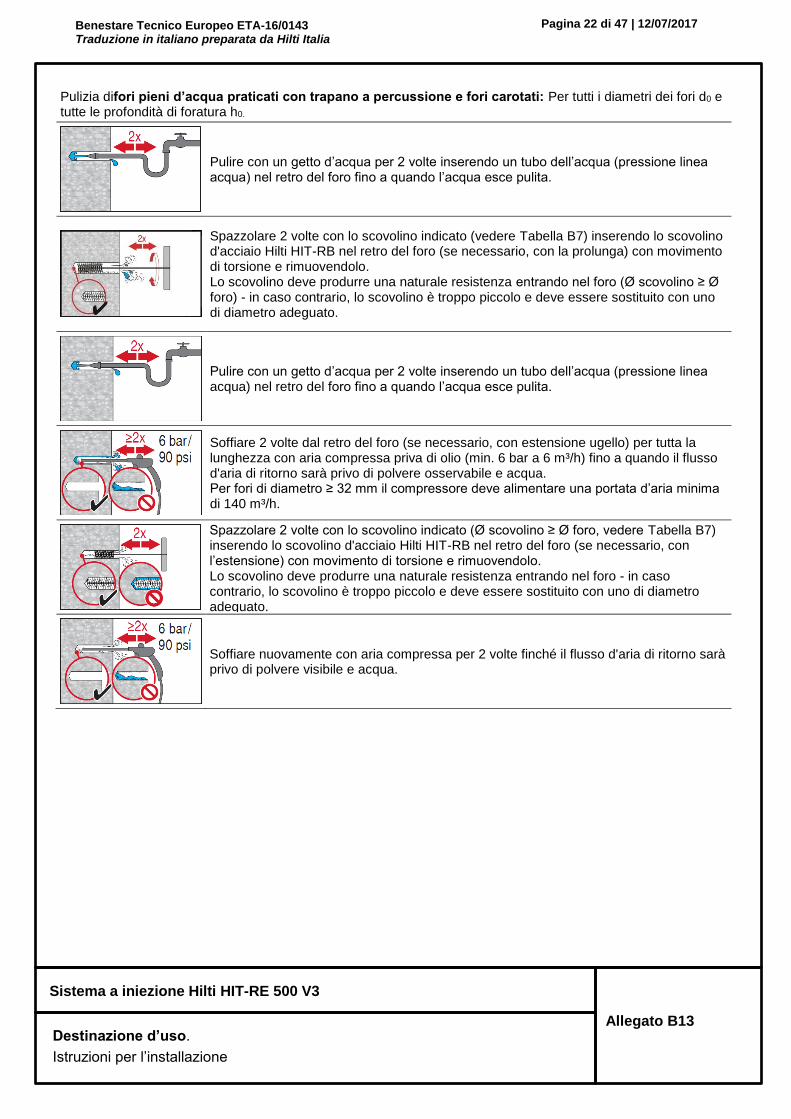
Benestare Tecnico Europeo ETA-16/0143 Traduzione in italiano preparata da Hilti Italia
Pagina 22 di 47 | 12/07/2017
Sistema a iniezione Hilti HIT-RE 500 V3
Allegato B13 Destinazione d’uso.
Istruzioni per l’installazione
Pulizia difori pieni d’acqua praticati con trapano a percussione e fori carotati: Per tutti i diametri dei fori d0 e tutte le profondità di foratura h0.
Pulire con un getto d’acqua per 2 volte inserendo un tubo dell’acqua (pressione linea acqua) nel retro del foro fino a quando l’acqua esce pulita.
Spazzolare 2 volte con lo scovolino indicato (vedere Tabella B7) inserendo lo scovolino d'acciaio Hilti HIT-RB nel retro del foro (se necessario, con la prolunga) con movimento di torsione e rimuovendolo. Lo scovolino deve produrre una naturale resistenza entrando nel foro (Ø scovolino ≥ Ø foro) - in caso contrario, lo scovolino è troppo piccolo e deve essere sostituito con uno di diametro adeguato.
Pulire con un getto d’acqua per 2 volte inserendo un tubo dell’acqua (pressione linea acqua) nel retro del foro fino a quando l’acqua esce pulita.
Soffiare 2 volte dal retro del foro (se necessario, con estensione ugello) per tutta la lunghezza con aria compressa priva di olio (min. 6 bar a 6 m³/h) fino a quando il flusso d'aria di ritorno sarà privo di polvere osservabile e acqua. Per fori di diametro ≥ 32 mm il compressore deve alimentare una portata d’aria minima di 140 m³/h.
Spazzolare 2 volte con lo scovolino indicato (Ø scovolino ≥ Ø foro, vedere Tabella B7) inserendo lo scovolino d'acciaio Hilti HIT-RB nel retro del foro (se necessario, con l’estensione) con movimento di torsione e rimuovendolo. Lo scovolino deve produrre una naturale resistenza entrando nel foro - in caso contrario, lo scovolino è troppo piccolo e deve essere sostituito con uno di diametro adeguato.
Soffiare nuovamente con aria compressa per 2 volte finché il flusso d'aria di ritorno sarà privo di polvere visibile e acqua.

Benestare Tecnico Europeo ETA-16/0143 Traduzione in italiano preparata da Hilti Italia
Pagina 23 di 47 | 12/07/2017
Sistema a iniezione Hilti HIT-RE 500 V3
Allegato B14 Destinazione d’uso.
Istruzioni per l’installazione
Pulizia di fori carotati con strumento di irruvidimento Hilti TE-YRT: Per tutti i diametri dei fori d0 e tutte le profondità di foratura h0.
Pulire con un getto d’acqua per 2 volte inserendo un tubo dell’acqua (pressione linea acqua) nel retro del foro fino a quando l’acqua esce pulita.
Spazzolare 2 volte con lo scovolino indicato (vedere Tabella B7) inserendo lo scovolino d'acciaio Hilti HIT-RB nel retro del foro (se necessario, con la prolunga) con movimento di torsione e rimuovendolo. Lo scovolino deve produrre una naturale resistenza entrando nel foro (Ø scovolino ≥ Ø foro) - in caso contrario, lo scovolino è troppo piccolo e deve essere sostituito con uno di diametro adeguato.
Soffiare 2 volte dal retro del foro (se necessario, con estensione ugello) per tutta la lunghezza con aria compressa priva di olio (min. 6 bar a 6 m³/h) fino a quando il flusso d'aria di ritorno sarà privo di polvere osservabile e acqua. Per fori di diametro ≥ 32 mm il compressore deve alimentare una portata d’aria minima di 140 m³/h.

Benestare Tecnico Europeo ETA-16/0143 Traduzione in italiano preparata da Hilti Italia
Pagina 24 di 47 | 12/07/2017
Sistema a iniezione Hilti HIT-RE 500 V3
Allegato B15 Destinazione d’uso.
Istruzioni per l’installazione
Preparazione dell'iniezione
Fissare saldamente l'ugello di miscelazione HIT-RE-M al collettore della cartuccia. Non modificare l'ugello di miscelazione. Attenersi alle istruzioni per l'uso del dispenser. Controllare il corretto funzionamento del portacartucce. Inserire la cartuccia nel supporto e posizionare il supporto nel dispenser.
La cartuccia si apre automaticamente all’inizio dell’erogazione. In base al formato della cartuccia occorre eliminare una quantità iniziale di resina. Le quantità eliminate sono: 3 corse per cartuccia da 330 ml, 4 corse per cartuccia da 500 ml, 65 ml per cartuccia da 1400 ml.
Iniettare la resina dal retro del foro senza formare bolle d'aria.
Iniettare la resina partendo dal retro del foro, ritirando lentamente il miscelatore a ogni pressione del grilletto. Riempire circa 2/3 del foro per garantire che l'intercapedine anulare tra l'ancorante e il calcestruzzo sia completamente piena di resina lungo la lunghezza di posa.
Al termine dell'iniezione, depressurizzare il dispenser premendo l'apposito grilletto. Ciò previene l'ulteriore erogazione di resina dal miscelatore.
Installazione a soffitto e/o installazione con profondità di posa hef > 250 mm. Per l'installazione a soffitto, l'iniezione è possibile solamente con l'ausilio di estensioni e galleggianti. Assemblare il miscelatore HIT-RE-M, le prolunghe e un galleggiante di dimensioni adeguate (vedere Tabella B7). Inserire il galleggiante nel retro del foro e iniettare la resina. Durante l'iniezione, il galleggiante viene naturalmente espulso dal foro dalla pressione della resina.
Posa dell’elemento Immediatamente prima della posa di un ancorante, il foro deve essere privo di polvere e detriti.
Prima dell'uso, verificare che l'elemento sia asciutto e privo di olio e altri contaminanti. Contrassegnare e posare l'elemento alla profondità di posa necessaria prima che trascorra il tempo di lavorazione twork. Il tempo di lavorazione twork è indicato nella Tabella B6.
Per l'installazione a soffitto, usare i galleggianti e fissare le parti integrate, ad es., mediante cunei.
Caricamento dell'ancorante: Una volta trascorso il tempo di indurimento tcure necessario (vedere Tabella B6) è possibile caricare l'ancorante. La coppia di installazione applicata non deve superare i valori Tmax indicati nelle tabelle B1, B2, B3 e B4.

Benestare Tecnico Europeo ETA-16/0143 Traduzione in italiano preparata da Hilti Italia
Pagina 25 di 47 | 12/07/2017
Sistema a iniezione Hilti HIT-RE 500 V3
Allegato B16 Destinazione d’uso.
Istruzioni per l’installazione
Installazione del set di riempimento
Utilizzare il set di riempimento Hilti con dado standard. Rispettare il corretto orientamento di rondella di riempimento e rondella sferica.
La coppia di installazione applicata non deve superare i valori Tmax indicati nelle Tabelle dalla Errore. L'origine riferimento non è stata trovata.1 fino alla B5.
Optional: Installazione del dado di bloccaggio. Serrare con ¼ fino a ½ giro. (Non per formato M24.)
Riempire il giunto anulare tra la barra di ancoraggio e il fissaggio con 1-3 corse di resina a iniezione Hilti HIT-RE 500 V3. Seguire le istruzioni per l’installazione fornite a corredo della cartuccia HIT-RE 500 V3.

Benestare Tecnico Europeo ETA-16/0143 Traduzione in italiano preparata da Hilti Italia
Pagina 26 di 47 | 12/07/2017
Sistema a iniezione Hilti HIT-RE 500 V3
Allegato C1 Prestazioni Resistenza caratteristica sotto carichi di trazione nel calcestruzzo Progettazione ai sensi di “Rapporto Tecnico EOTA TR 029, 09/2010” o “CEN/TS 1992-4:2009”
Tabella C1: Resistenza caratteristica per barre filettate sotto carichi di trazione nel calcestruzzo
Barra filettata, HIT-V-..., AM…8.8 M8 M10 M12 M16 M20 M24 M27 M30
Fattore di sicurezza dell’installazione
Trapano a percussione 21) = inst
2) [-] 1,0
Rotopercussione con punta cava per perforatori Hilti TE-CD o TE-YD
21) = inst
2) [-] - 1,0
Carotaggio a diamante 21) = inst
2) [-] 1,2 1,4
Carotaggio a diamante con irruvidimento con strumento apposito di Hilti TE-YRT
21) = inst
2) [-] - 1,0
Rotopercussione in fori pieni d’acqua 21) = inst
2) [-] 1,4
Cedimento dell’acciaio barre filettate
Resistenza caratteristica NRk,s [kN] As · fuk
Fattore di sicurezza parziale qualità 5.8 Ms,N [-] 1,5
Fattore di sicurezza parziale qualità 8.8 Ms,N [-] 1,5
Fattore di sicurezza parziale HIT-V-R Ms,N [-] 1,87 2,86
Fattore di sicurezza parziale HIT-V-HCR Ms,N [-] 1,5 2,1
Estrazione combinata e rottura del cono di calcestruzzo
Resistenza di adesione caratteristica nel calcestruzzo non fessurato C20/25 in fori praticati con trapano a percussione e con punta cava per perforatori Hilti TE-CD o TE-YD e fori carotati con irruvidimento con apposito strumento Hilti TE-YRT
Intervallo di temperatura I: 40°C / 24°C Rk,ucr [N/mm2] 18 18 17 16 15 15 14 13
Intervallo di temperatura II: 70°C / 43°C Rk,ucr [N/mm2] 14 13 13 12 12 11 10 10
Resistenza di adesione caratteristica nel calcestruzzo non fessurato C20/25 in fori carotati.
Intervallo di temperatura I: 40°C / 24°C Rk,ucr [N/mm2] 12 12 12 12 12 11 11 11
Intervallo di temperatura II: 70°C / 43°C Rk,ucr [N/mm2] 9,5 9 9 9 9 8,5 8,5 8,5
Resistenza di adesione caratteristica nel calcestruzzo non fessurato C20/25 in fori praticati con trapano a percussione e installazione in fori pieni d’acqua
Intervallo di temperatura I: 40°C / 24°C Rk,ucr [N/mm2] 15 15 15 14 13 12 12 11
Intervallo di temperatura II: 70°C / 43°C Rk,ucr [N/mm2] 12 11 11 10 10 9,5 9 8,5
Fattore secondo par. 6.2.2.3 di CEN/TS 1992-4:2009 parte 5
k82) [-] 10,1
Resistenza di aderenza caratteristica nel calcestruzzo fessurato C20/25 in fori praticati con trapano a percussione e con punta cava per perforatori Hilti TE-CD o TE-YD e fori carotati con irruvidimento con apposito strumento Hilti TE-YRT
Intervallo di temperatura I: 40°C / 24°C Rk,cr [N/mm2] 6,5 7,5 8 8 8 8 8 8
Intervallo di temperatura II: 70°C / 43°C Rk,cr [N/mm2] 5,5 6 6 6 6 6 6 6
Fattore secondo par. 6.2.2.3 di CEN/TS 1992-4:2009 parte 5
k82) [-] 7,2

Benestare Tecnico Europeo ETA-16/0143 Traduzione in italiano preparata da Hilti Italia
Pagina 27 di 47 | 12/07/2017
Sistema a iniezione Hilti HIT-RE 500 V3
Allegato C2 Prestazioni Resistenza caratteristica sotto carichi di trazione nel calcestruzzo Progettazione ai sensi di “Rapporto Tecnico EOTA TR 029, 09/2010” o “CEN/TS 1992-4:2009”
Tabella C1: segue
Barra filettata, HIT-V-..., AM…8.8 M8 M10 M12 M16 M20 M24 M27 M30
Estrazione combinata e rottura del cono di calcestruzzo (segue)
Fattori di incremento
per Rk nel calcestruzzo
in fori praticati con trapano a percussione e fori praticati con trapano a percussione con punta cava per perforatori Hilti TE-CD o TE-YD e fori carotati
c
C30/37 1,04
C40/50 1,07
C50/60 1,09
in fori carotati con strumento di irruvidimento Hilti TE-YRT
c C50/60 - 1,0
Rottura del cono di calcestruzzo
Fattore secondo par. 6.2.3 di CEN/TS 1992-4:2009 parte 5
kucr2) [-] 10,1
kcr2) [-] 7,2
Distanza dal bordo ccr,N [mm] 1,5 hef
Interasse scr,N [mm] 3,0 hef
Rottura dovuta a fessurazione
Fattore secondo par. 6.2.3 di CEN/TS 1992-4:2009 parte 5
kucr2) [-] 10,1
kcr2) [-] 7,2
Distanza dal bordo ccr,sp [mm] per
h / hef ≥ 2,0 1,0 hef
2,0 > h / hef > 1,3 4,6 hef - 1,8 h
h / hef ≤ 1,3 2,26 hef
Interasse scr,sp [mm] 2 ccr,sp
1) Parametro per progettazione ai sensi del Rapporto Tecnico EOTA TR 029. 2) Parametro di progettazione ai sensi di CEN/TS 1992-4:2009.
ccr,sp
h/hef
1,3
2,0
1,0 hef 2,26 hef

Benestare Tecnico Europeo ETA-16/0143 Traduzione in italiano preparata da Hilti Italia
Pagina 28 di 47 | 12/07/2017
Sistema a iniezione Hilti HIT-RE 500 V3
Allegato C3 Prestazioni Resistenza caratteristica sotto carichi di trazione nel calcestruzzo Progettazione ai sensi di “Rapporto Tecnico EOTA TR 029, 09/2010” o “CEN/TS 1992-4:2009”
Tabella C2: Resistenza caratteristica per bussola a filetto interno HIS-(R)N sotto carichi di trazione nel calcestruzzo
HIS-(R)N M8 M10 M12 M16 M20
Diametro esterno della bussola d1) = dnom2) [mm] 12,5 16,5 20,5 25,4 27,6
Fattore di sicurezza dell’installazione
Trapano a percussione 21) = inst
2) [-] 1,0
Rotopercussione con punta cava per perforatori Hilti TE-CD o TE-YD
21) = inst
2) [-] 1,0
Carotaggio a diamante 21) = inst
2) [-] 1,2 1,4
Carotaggio a diamante con irruvidimento con strumento apposito di Hilti TE-YRT
21) = inst
2) [-] - 1,0
Rotopercussione in fori pieni d’acqua 21) = inst
2) [-] 1,4
Cedimento dell’acciaio
Resistenza caratteristica HIS-N con vite qualità 8.8
NRk,s [kN] 25 46 67 125 116
Fattore di sicurezza parziale Ms,N [-] 1,5
Resistenza caratteristica HIS-RN con vite qualità 70
NRk,s [kN] 26 41 59 110 166
Fattore di sicurezza parziale Ms,N [-] 1,87 2,4
Estrazione combinata e rottura del cono di calcestruzzo3)
Resistenza di adesione caratteristica nel calcestruzzo non fessurato C20/25 in fori praticati con trapano a percussione e fori praticati con trapano a percussione con punta cava per perforatori Hilti TE-CD o TE-YD e fori carotati con irruvidimento con apposito strumento Hilti TE-YRT
Intervallo di temperatura I: 40°C / 24°C Rk,ucr [N/mm2] 13 13 13 13 13
Intervallo di temperatura II: 70°C / 43°C Rk,ucr [N/mm2] 10 10 10 10 10
Resistenza di adesione caratteristica nel calcestruzzo non fessurato C20/25 in fori carotati.
Intervallo di temperatura I: 40°C / 24°C Rk,ucr [N/mm2] 8,5 8,5 9 9 9,5
Intervallo di temperatura II: 70°C / 43°C Rk,ucr [N/mm2] 6,5 6,5 6,5 7 7
Resistenza di adesione caratteristica nel calcestruzzo non fessurato C20/25 in fori praticati con trapano a percussione e installazione in fori pieni d’acqua
Intervallo di temperatura I: 40°C / 24°C Rk,ucr [N/mm2] 11 11 11 11 11
Intervallo di temperatura II: 70°C / 43°C Rk,ucr [N/mm2] 8,5 8,5 8,5 8,5 8,5
Fattore secondo par. 6.2.2.3 di CEN/TS 1992-4:2009 parte 5
k83) [-] 10,1

Benestare Tecnico Europeo ETA-16/0143 Traduzione in italiano preparata da Hilti Italia
Pagina 29 di 47 | 12/07/2017
Sistema a iniezione Hilti HIT-RE 500 V3
Allegato C4 Prestazioni Resistenza caratteristica sotto carichi di trazione nel calcestruzzo Progettazione ai sensi di “Rapporto Tecnico EOTA TR 029, 09/2010” o “CEN/TS 1992-4:2009”
Tabella C2: segue
HIS-(R)N M8 M10 M12 M16 M20
Estrazione combinata e rottura del cono di calcestruzzo3) (segue)
Resistenza di aderenza caratteristica nel calcestruzzo fessurato C20/25 in fori praticati con trapano a percussione e fori praticati con trapano a percussione con punta cava per perforatori Hilti TE-CD o TE-YD e fori carotati con irruvidimento con apposito strumento Hilti TE-YRT
Intervallo di temperatura I: 40°C / 24°C Rk,cr [N/mm2] 8,5 8,5 8,5 8,5 8,5
Intervallo di temperatura II: 70°C / 43°C Rk,cr [N/mm2] 7 7 7 7 7
Fattore secondo par. 6.2.2.3 di CEN/TS 1992-4:2009 parte 5
k82) [-] 7,2
Fattori di incremento
per Rk nel calcestruzzo
in fori praticati con trapano a percussione e fori praticati con trapano a percussione con punta cava per perforatori Hilti TE-CD o TE-YD e fori carotati
c
C30/37 1,04
C40/50 1,07
C50/60 1,09
in fori carotati con strumento di irruvidimento Hilti TE-YRT
c C50/60 - 1,0
Rottura del cono di calcestruzzo
Fattore secondo par. 6.2.3 di CEN/TS 1992-4:2009 parte 5
kucr2) [-] 10,1
kcr2) [-] 7,2
Distanza dal bordo ccr,N [mm] 1,5 hef
Interasse scr,N [mm] 3,0 hef
Rottura dovuta a fessurazione
Fattore secondo par. 6.2.3 di CEN/TS 1992-4:2009 parte 5
kucr2) [-] 10,1
kcr2) [-] 7,2
Distanza dal bordo ccr,sp [mm] per
h / hef ≥ 2,0 1,0 hef
2,0 > h / hef > 1,3 4,6 hef - 1,8 h
h / hef ≤ 1,3 2,26 hef
Interasse scr,sp [mm] 2 ccr,sp
1) Parametro per progettazione ai sensi del Rapporto Tecnico EOTA TR 029. 2) Parametro di progettazione ai sensi di CEN/TS 1992-4:2009. 3) Per progettazione ai sensi della CEN/TS 1992-1:2009, i valori caratteristici del carico di trazione possono essere
calcolati dalla resistenza di adesione caratteristica per estrazione combinata a sfilamento e rottura del cono di calcestruzzo ai sensi di:
NRk = Rk · (hef · d1 · ).
ccr,sp
h/hef
1,3
2,0
1,0 hef 2,26 hef

Benestare Tecnico Europeo ETA-16/0143 Traduzione in italiano preparata da Hilti Italia
Pagina 30 di 47 | 12/07/2017
Sistema a iniezione Hilti HIT-RE 500 V3
Allegato C5 Prestazioni Resistenza caratteristica sotto carichi di trazione nel calcestruzzo Progettazione ai sensi di “Rapporto Tecnico EOTA TR 029, 09/2010” o “CEN/TS 1992-4:2009”
Tabella C3: Resistenza caratteristica per ancorante a trazione Hilti HZA / HZA-R sotto carichi di trazione nel calcestruzzo
HZA / HZA-R M12 M16 M20 M24 M27
Diametro ferro di ripresa [mm] 12 16 20 25 28
Fattore di sicurezza dell’installazione
Trapano a percussione 21) = inst
2) [-] 1,0
Rotopercussione con punta cava per perforatori Hilti TE-CD o TE-YD
21) = inst
2) [-] 1,0
Carotaggio a diamante 21) = inst
2) [-] 1,2 1,4
Carotaggio a diamante con irruvidimento con strumento apposito di Hilti TE-YRT
21) = inst
2) [-] - 1,0
Rotopercussione in fori pieni d’acqua 21) = inst
2) [-] 1,4
Cedimento dell’acciaio
Resistenza caratteristica HZA NRk,s [kN] 46 86 135 194 252
Resistenza caratteristica HZA-R NRk,s [kN] 62 111 173 249 -
Fattore di sicurezza parziale Ms,N [-] 1,4
Estrazione combinata e rottura del cono di calcestruzzo
Resistenza di adesione caratteristica nel calcestruzzo non fessurato C20/25 in fori praticati con trapano a percussione e fori praticati con trapano a percussione con punta cava per perforatori Hilti TE-CD o TE-YD e fori carotati con irruvidimento con apposito strumento Hilti TE-YRT
Intervallo di temperatura I: 40°C / 24°C Rk,ucr [N/mm2] 14 14 14 13 13
Intervallo di temperatura II: 70°C / 43°C Rk,ucr [N/mm2] 11 10 10 10 9,5
Resistenza di adesione caratteristica nel calcestruzzo non fessurato C20/25 in fori carotati.
Intervallo di temperatura I: 40°C / 24°C Rk,ucr [N/mm2] 9 9 9 9 9,5
Intervallo di temperatura II: 70°C / 43°C Rk,ucr [N/mm2] 6,5 6,5 7 7 7
Resistenza di adesione caratteristica nel calcestruzzo non fessurato C20/25 in fori praticati con trapano a percussione e installazione in fori pieni d’acqua
Intervallo di temperatura I: 40°C / 24°C Rk,ucr [N/mm2] 12 12 12 11 11
Intervallo di temperatura II: 70°C / 43°C Rk,ucr [N/mm2] 9 9 8,5 8,5 8,5
Fattore secondo par. 6.2.2.3 di CEN/TS 1992-4:2009 parte 5
k83) [-] 10,1

Benestare Tecnico Europeo ETA-16/0143 Traduzione in italiano preparata da Hilti Italia
Pagina 31 di 47 | 12/07/2017
Sistema a iniezione Hilti HIT-RE 500 V3
Allegato C6 Prestazioni Resistenza caratteristica sotto carico di taglio nel calcestruzzo Progettazione ai sensi di “Rapporto Tecnico EOTA TR 029, 09/2010” o “CEN/TS 1992-4:2009”
Tabella C3: segue
HZA / HZA-R M12 M16 M20 M24 M27
Diametro ferro di ripresa [mm] 12 16 20 25 28
Estrazione combinata e rottura del cono di calcestruzzo (segue)
Resistenza di aderenza caratteristica nel calcestruzzo fessurato C20/25 in fori praticati con trapano a percussione e fori praticati con trapano a percussione con punta cava per perforatori Hilti TE-CD o TE-YD e fori carotati con irruvidimento con apposito strumento Hilti TE-YRT
Intervallo di temperatura I: 40°C / 24°C
Rk,cr [N/mm2] 9,5 9,5 10 10 11
Intervallo di temperatura II: 70°C / 43°C Rk,cr [N/mm2] 8 8 8 8 8
Fattore secondo par. 6.2.2.3 di CEN/TS 1992-4:2009 parte 5
k82) [-] 7,2
Fattori di incremento
per Rk nel calcestruzzo
in fori praticati con trapano a percussione e fori praticati con trapano a percussione con punta cava per perforatori Hilti TE-CD o TE-YD e fori carotati
c
C30/37 1,04
C40/50 1,07
C50/60 1,09
in fori carotati con strumento di irruvidimento Hilti TE-YRT
c C50/60 1,0
Profondità di posa effettiva per calcolo di N0
Rk,p in base a Eq. 5.2a (TR 029 §5.2.2.4)
HZA hef [mm] hnom -20
HZA-R hef [mm] hnom -100 -
Rottura del cono di calcestruzzo
Profondità di posa per calcolo di N0Rk,c in
base a eq. 5.3a (TR 029 §5.2.2.4) hef [mm] hnom
Fattore secondo par. 6.2.3 di CEN/TS 1992-4:2009 parte 5
kucr2) [-] 10,1
kcr2) [-] 7,2
Distanza dal bordo ccr,N [mm] 1,5 hef
Interasse scr,N [mm] 3,0 hef
Rottura dovuta a fessurazione
Fattore secondo par. 6.2.3 di CEN/TS 1992-4:2009 parte 5
kucr2) [-] 10,1
kcr2) [-] 7,2
Distanza dal bordo ccr,sp [mm] per
h / hef ≥ 2,0 1,0 hef
2,0 > h / hef > 1,3 4,6 hef - 1,8 h
h / hef ≤ 1,3 2,26 hef
Interasse scr,sp [mm] 2 ccr,sp
1) Parametro per progettazione ai sensi del Rapporto Tecnico EOTA TR 029. 2) Parametro di progettazione ai sensi di CEN/TS 1992-4:2009.
ccr,sp
h/hef
1,3
2,0
1,0 hef 2,26 hef

Benestare Tecnico Europeo ETA-16/0143 Traduzione in italiano preparata da Hilti Italia
Pagina 32 di 47 | 12/07/2017
Sistema a iniezione Hilti HIT-RE 500 V3
Allegato C7 Prestazioni Resistenza caratteristica sotto carico di taglio nel calcestruzzo Progettazione ai sensi di “Rapporto Tecnico EOTA TR 029, 09/2010” o “CEN/TS 1992-4:2009”
Tabella C4: Resistenza caratteristica per barre di rinforzo (ferri di ripresa) sotto carichi di trazione nel calcestruzzo
Ferro di armatura (ferro di ripresa) 8 10 12 14 16 20 25 28 30 32
Fattore di sicurezza dell’installazione
Trapano a percussione 21) = inst
2) [-] 1,0
Rotopercussione con punta cava per perforatori Hilti TE-CD o TE-YD
21) = inst
2) [-] - 1,0 -
Carotaggio a diamante 21) = inst
2) [-] 1,2 1,4
Carotaggio a diamante con irruvidimento con strumento apposito di Hilti TE-YRT
21) = inst
2) [-] - 1,0 -
Rotopercussione in fori pieni d’acqua 21) = inst
2) [-] 1,4
Cedimento dell’acciaio ferri di ripresa
Resistenza caratteristica per ferro di ripresa B500B ai sensi DIN 488:2009-08 1)
NRk,s [kN] 28 43 62 85 111 173 270 339 388 442
Fattore di sicurezza parziale per ferro di ripresa B500B ai sensi DIN 488:2009-08 1)
Ms,N [-] 1,4
Estrazione combinata e rottura del cono di calcestruzzo
Resistenza di adesione caratteristica nel calcestruzzo non fessurato C20/25 in fori praticati con trapano a percussione e fori praticati con trapano a percussione con punta cava per perforatori Hilti TE-CD o TE-YD e fori carotati con irruvidimento con apposito strumento Hilti TE-YRT
Intervallo di temperatura I: 40°C / 24°C
Rk,ucr [N/mm2] 9,5 14 14 14 14 14 13 13 13 13
Intervallo di temperatura II: 70°C / 43°C Rk,ucr [N/mm2] 7 11 11 11 10 10 10 9,5 9,5 9,5
Resistenza di adesione caratteristica nel calcestruzzo non fessurato C20/25 in fori carotati.
Intervallo di temperatura I: 40°C / 24°C
Rk,ucr [N/mm2] 9 9 9 9 9 9 9 9,5 9,5 9,5
Intervallo di temperatura II: 70°C / 43°C Rk,ucr [N/mm2] 6,5 6,5 6,5 6,5 6,5 7 7 7 7 7
Resistenza di adesione caratteristica nel calcestruzzo non fessurato C20/25 in fori praticati con trapano a percussione e installazione in fori pieni d’acqua
Intervallo di temperatura I: 40°C / 24°C
Rk,ucr [N/mm2] 8 12 12 12 12 12 11 11 11 11
Intervallo di temperatura II: 70°C / 43°C Rk,ucr [N/mm2] 5,5 9 9 9 9 8,5 8,5 8,5 8 8
Fattore secondo par. 6.2.2.3 di CEN/TS 1992-4:2009 parte 5
k8 [-] 10,1
1) I valori devono essere calcolati ai sensi del Rapporto Tecnico EOTA TR 029, Eq. 3.3a ed Eq. 5.1, se i ferri di ripresa non soddisfano i requisiti ai sensi della DIN 488.

Benestare Tecnico Europeo ETA-16/0143 Traduzione in italiano preparata da Hilti Italia
Pagina 33 di 47 | 12/07/2017
Sistema a iniezione Hilti HIT-RE 500 V3
Allegato C8 Prestazioni Resistenza caratteristica sotto carichi di trazione nel calcestruzzo Progettazione ai sensi di “Rapporto Tecnico EOTA TR 029, 09/2010” o “CEN/TS 1992-4:2009”
Tabella C4: segue
Ferro di armatura (ferro di ripresa) 8 10 12 14 16 20 25 28 30 32
Estrazione combinata e rottura del cono di calcestruzzo (segue)
Resistenza di aderenza caratteristica nel calcestruzzo fessurato C20/25 in fori praticati con trapano a percussione e fori praticati con trapano a percussione con punta cava per perforatori Hilti TE-CD o TE-YD e fori carotati con irruvidimento con apposito strumento Hilti TE-YRT
Intervallo di temperatura I: 40°C / 24°C
Rk,cr [N/mm2] 4,5 8,5 9,5 9,5 9,5 10 10 11 11 11
Intervallo di temperatura II: 70°C / 43°C Rk,cr [N/mm2] 4 7 8 8 8 8 8 8 8 8
Fattore secondo par. 6.2.2.3 di CEN/TS 1992-4:2009 parte 5
k82) [-] 7,2
Fattori di incremento
per Rk nel calcestruzzo
in fori praticati con trapano a percussione e fori praticati con trapano a percussione con punta cava per perforatori Hilti TE-CD o TE-YD e fori carotati
c
C30/37 1,04
C40/50 1,07
C50/60 1,09
in fori carotati con strumento di irruvidimento Hilti TE-YRT
c C50/60 1,0
Rottura del cono di calcestruzzo
Estrazione combinata e rottura del cono di calcestruzzo
Fattore secondo par. 6.2.3 di CEN/TS 1992-4:2009 parte 5
kucr2) [-] 10,1
kcr2) [-] 7,2
Distanza dal bordo ccr,N [mm] 1,5 hef
Interasse scr,N [mm] 3,0 hef
Rottura dovuta a fessurazione
Fattore secondo par. 6.2.3 di CEN/TS 1992-4:2009 parte 5
kucr2) [-] 10,1
kcr2) [-] 7,2
Distanza dal bordo ccr,sp [mm] per
h / hef ≥ 2,0 1,0 hef
2,0 > h / hef > 1,3 4,6 hef - 1,8 h
h / hef ≤ 1,3 2,26 hef
Interasse scr,sp [mm] 2 ccr,sp
1) Parametro per progettazione ai sensi del Rapporto Tecnico EOTA TR 029. 2) Parametro di progettazione ai sensi di CEN/TS 1992-4:2009.
ccr,sp
h/hef
1,3
2,0
1,0 hef 2,26 hef

Benestare Tecnico Europeo ETA-16/0143 Traduzione in italiano preparata da Hilti Italia
Pagina 34 di 47 | 12/07/2017
Sistema a iniezione Hilti HIT-RE 500 V3
Allegato C9 Prestazioni Resistenza caratteristica sotto carico di taglio nel calcestruzzo Progettazione ai sensi di “Rapporto Tecnico EOTA TR 029, 09/2010” o “CEN/TS 1992-4:2009”
Tabella C5: Resistenza caratteristica per barre filettate sotto carico di taglio nel calcestruzzo
Barra filettata, HIT-V-..., AM…8.8 M8 M10 M12 M16 M20 M24 M27 M30
Fattore di sicurezza parziale
Cedimento riferito ad acciaio qualità 5.8
Ms,v [-] 1,25
Cedimento riferito ad acciaio qualità 8.8
Ms,v [-]
1,25
Cedimento riferito ad acciaio HIT-V-R
Ms,v[-]
1,56 2,38
Cedimento riferito ad acciaio HIT-V-HCR
Ms,v[-]
1,25 1,75
Cedimento dell'acciaio senza braccio di leva per barra filettata, HIT-V
Fattore secondo paragrafo 6.3.2.1 di CEN/TS 1992-4:2009 parte 5
k22) [-] 1,0
Resistenza caratteristica VRk,s [kN] 0,5 · As · fuk
Cedimento dell'acciaio con braccio di leva per barra filettata, HIT-V
Resistenza caratteristica M0Rk,s [Nm] 1,2 · Wel · fuk
Rottura da scalzamento del calcestruzzo
Fattore in equazione (5.7) di TR 029 oppure secondo equazione (27) di CEN/TS 1992-4:2009 parte 5
k1) = k32) [-] 2,0
Cedimento per rottura del bordo del calcestruzzo
Vedere paragrafo 5.2.3.4 di TR 029 “Progettazione di ancoranti chimici”
1) Parametro di progettazione ai sensi di “Rapporto Tecnico EOTA TR 029”. 2) Parametro di progettazione ai sensi di CEN/TS 1992-4:2009.

Benestare Tecnico Europeo ETA-16/0143 Traduzione in italiano preparata da Hilti Italia
Pagina 35 di 47 | 12/07/2017
Sistema a iniezione Hilti HIT-RE 500 V3
Allegato C10 Prestazioni Resistenza caratteristica sotto carico di taglio nel calcestruzzo Progettazione ai sensi di “Rapporto Tecnico EOTA TR 029, 09/2010” o “CEN/TS 1992-4:2009”
Tabella C6: Resistenza caratteristica per bussola a filetto interno HIS-(R)N sotto carico di taglio nel calcestruzzo
HIS-(R)N M8 M10 M12 M16 M20
Cedimento dell'acciaio senza braccio di leva
Fattore secondo paragrafo 6.3.2.1 di CEN/TS 1992-4:2009 parte 5
k22) [-] 1,0
Resistenza caratteristica HIS-N vite classe 8.8
VRk,s [kN] 13 23 34 63 58
Fattore di sicurezza parziale Ms,v [-] 1,25
Resistenza caratteristica HIS-RN vite classe 70
VRk,s [kN] 13 20 30 55 83
Fattore di sicurezza parziale Ms,v [-] 1,56 2,0
Cedimento dell'acciaio con braccio di leva
Resistenza caratteristica HIS-N vite classe 8.8
M0Rk,s [Nm] 30 60 105 266 519
Fattore di sicurezza parziale Ms,v [-] 1,25
Resistenza caratteristica HIS-RN vite classe 70
M0Rk,s [Nm] 26 52 92 233 454
Fattore di sicurezza parziale Ms,v [-] 1,56
Rottura da scalzamento del calcestruzzo
Fattore in equazione (5.7) di TR 029 oppure secondo equazione (27) di CEN/TS 1992-4:2009 parte 5
k1) = k32) [-] 2,0
Rottura del bordo del calcestruzzo vedere TR 029
Vedere paragrafo 5.2.3.4 di TR 029 “Progettazione di ancoranti chimici”
1) Parametro di progettazione ai sensi di “Rapporto Tecnico EOTA TR 029”. 2) Parametro di progettazione ai sensi di CEN/TS 1992-4:2009.

Benestare Tecnico Europeo ETA-16/0143 Traduzione in italiano preparata da Hilti Italia
Pagina 36 di 47 | 12/07/2017
Sistema a iniezione Hilti HIT-RE 500 V3
Allegato C11 Prestazioni Resistenza caratteristica sotto carico di taglio nel calcestruzzo Progettazione ai sensi di “Rapporto Tecnico EOTA TR 029, 09/2010” o “CEN/TS 1992-4:2009”
Tabella C7: Resistenza caratteristica per ancorante a trazione Hilti HZA / HZA-R sotto carico di taglio nel calcestruzzo
HZA / HZA-R M12 M16 M20 M24 M27
Diametro ferro di ripresa [mm] 12 16 20 25 28
Cedimento dell'acciaio senza braccio di leva
Fattore secondo paragrafo 6.3.2.1 di CEN/TS 1992-4:2009 parte 5
k22) [-] 1,0
Resistenza caratteristica HZA VRk,s [kN] 23 43 67 97 126
Resistenza caratteristica HZA-R VRk,s [kN] 31 55 86 124 -
Fattore di sicurezza parziale Ms,v [-] 1,5
Cedimento dell'acciaio con braccio di leva
Resistenza caratteristica HZA M0Rk,s [Nm] 72 183 357 617 915
Resistenza caratteristica HZA-R M0Rk,s [Nm] 97 234 458 790 -
Fattore di sicurezza parziale Ms,v [-] 1,5
Rottura da scalzamento del calcestruzzo
Fattore in equazione (5.7) di TR 029 oppure secondo equazione (27) di CEN/TS 1992-4:2009 parte 5
k1) = k32) [-] 2,0
Rottura del bordo del calcestruzzo vedere TR 029
Vedere paragrafo 5.2.3.4 di TR 029 “Progettazione di ancoranti chimici”
1) Parametro di progettazione ai sensi di “Rapporto Tecnico EOTA TR 029”. 2) Parametro di progettazione ai sensi di CEN/TS 1992-4:2009.

Benestare Tecnico Europeo ETA-16/0143 Traduzione in italiano preparata da Hilti Italia
Pagina 37 di 47 | 12/07/2017
Sistema a iniezione Hilti HIT-RE 500 V3
Allegato C12 Prestazioni Resistenza caratteristica sotto carico di taglio nel calcestruzzo Progettazione ai sensi di “Rapporto Tecnico EOTA TR 029, 09/2010” o “CEN/TS 1992-4:2009”
Tabella C8: Resistenza caratteristica per barre di rinforzo (ferri di ripresa) sotto carico di taglio nel calcestruzzo
Ferro di armatura (ferro di ripresa) 8 10 12 14 16 20 25 28 30 32
Cedimento dell'acciaio senza braccio di leva
Fattore secondo paragrafo 6.3.2.1 di CEN/TS 1992-4:2009 parte 5
k22) [-] 1,0
Resistenza caratteristica per ferro di ripresa B500B ai sensi DIN 488:2009-083)
VRk,s [kN] 14 22 31 42 55 86 135 169 194 221
Fattore di sicurezza parziale per ferro di ripresa B500B ai sensi DIN 488:2009-083)
Ms,v [-] 1,5
Cedimento dell'acciaio con braccio di leva
Resistenza caratteristica M0Rk,s [Nm] 33 65 112 178 265 518 1012 1422 1749 2123
Fattore di sicurezza parziale Ms,v [-] 1,5
Rottura da scalzamento del calcestruzzo
Fattore in equazione (5.7) di TR 029 oppure secondo equazione (27) di CEN/TS 1992-4:2009 parte 5
k1) = k32) [-] 2,0
Rottura del bordo del calcestruzzo vedere TR 029
Vedere paragrafo 5.2.3.4 di TR 029 “Progettazione di ancoranti chimici”
1) Parametro di progettazione ai sensi di “Rapporto Tecnico EOTA TR 029”.
2) Parametro di progettazione ai sensi di CEN/TS 1992-4:2009. 3) I valori devono essere calcolati ai sensi di Rapporto Tecnico EOTA TR 029, Eq. 3.3b, Eq. 3.3c, Eq. 5.5 ed Eq. 5.6b,
se i ferri di ripresa non soddisfano i requisiti ai sensi della DIN 488.

Benestare Tecnico Europeo ETA-16/0143 Traduzione in italiano preparata da Hilti Italia
Pagina 38 di 47 | 12/07/2017
Sistema a iniezione Hilti HIT-RE 500 V3
Allegato C13 Prestazioni Spostamenti
Tabella C9: Spostamenti per barra filettata sotto carico di trazione
Barra filettata, HIT-V-..., AM…8.8 M8 M10 M12 M16 M20 M24 M27 M30
Calcestruzzo non fessurato
Intervallo di temperatura I: 40°C / 24°C
Spostamento N0 [mm/(N/mm²)] 0,04 0,05 0,05 0,06 0,06 0,07 0,08 0,08
Spostamento N [mm/(N/mm²)] 0,10 0,11 0,12 0,13 0,15 0,17 0,18 0,19
Intervallo di temperatura II: 70°C / 43°C
Spostamento N0 [mm/(N/mm²)] 0,05 0,05 0,06 0,07 0,07 0,08 0,09 0,10
Spostamento N [mm/(N/mm²)] 0,12 0,13 0,14 0,16 0,18 0,20 0,21 0,23
Calcestruzzo fessurato
Intervallo di temperatura I: 40°C / 24°C
Spostamento N0 [mm/(N/mm²)] 0,02 0,03 0,05 0,08 0,10 0,13 0,15 0,18
Spostamento N [mm/(N/mm²)] 0,12 0,19 0,14 0,19 0,16 0,16 0,15 0,18
Intervallo di temperatura II: 70°C / 43°C
Spostamento N0 [mm/(N/mm²)] 0,02 0,04 0,06 0,09 0,12 0,16 0,18 0,21
Spostamento N [mm/(N/mm²)] 0,15 0,23 0,17 0,23 0,19 0,19 0,18 0,21
Tabella C10: Spostamenti per barra filettata sotto carico di taglio
Barra filettata, HIT-V-..., AM…8.8 M8 M10 M12 M16 M20 M24 M27 M30
Spostamento V0 [mm/kN] 0,06 0,06 0,05 0,04 0,04 0,03 0,03 0,03
Spostamento V [mm/kN] 0,09 0,08 0,08 0,06 0,06 0,05 0,05 0,05

Benestare Tecnico Europeo ETA-16/0143 Traduzione in italiano preparata da Hilti Italia
Pagina 39 di 47 | 12/07/2017
Sistema a iniezione Hilti HIT-RE 500 V3
Allegato C14 Prestazioni Spostamenti
Tabella C11: Spostamenti per HIS-N sotto carico di trazione
HIS-(R)N M8 M10 M12 M16 M20
Calcestruzzo non fessurato
Intervallo di temperatura I: 40°C / 24°C
Spostamento N0 [mm/(N/mm²)] 0,05 0,06 0,06 0,07 0,08
Spostamento N [mm/(N/mm²)] 0,12 0,13 0,15 0,17 0,18
Intervallo di temperatura II: 70°C / 43°C
Spostamento N0 [mm/(N/mm²)] 0,06 0,07 0,07 0,08 0,09
Spostamento N [mm/(N/mm²)] 0,14 0,16 0,18 0,20 0,21
Calcestruzzo fessurato
Intervallo di temperatura I: 40°C / 24°C
Spostamento N0 [mm/(N/mm²)] 0,05 0,08 0,10 0,13 0,15
Spostamento N [mm/(N/mm²)] 0,14 0,19 0,16 0,16 0,15
Intervallo di temperatura II: 70°C / 43°C
Spostamento N0 [mm/(N/mm²)] 0,06 0,09 0,12 0,16 0,18
Spostamento N [mm/(N/mm²)] 0,17 0,23 0,19 0,19 0,18
Tabella C12: Spostamenti per HIS-N sotto carico di taglio
HIS-(R)N M8 M10 M12 M16 M20
Spostamento V0 [mm/kN] 0,06 0,06 0,05 0,04 0,04
Spostamento V [mm/kN] 0,09 0,08 0,08 0,06 0,06

Benestare Tecnico Europeo ETA-16/0143 Traduzione in italiano preparata da Hilti Italia
Pagina 40 di 47 | 12/07/2017
Sistema a iniezione Hilti HIT-RE 500 V3
Allegato C15 Prestazioni Spostamenti
Tabella C13: Spostamenti per ancorante a trazione Hilti HZA / HZA-R sotto carico di trazione
HZA / HZA-R M12 M16 M20 M24 M27
Calcestruzzo non fessurato
Intervallo di temperatura I: 40°C / 24°C
Spostamento N0 [mm/(N/mm²)] 0,05 0,06 0,06 0,07 0,08
Spostamento N [mm/(N/mm²)] 0,12 0,13 0,15 0,17 0,18
Intervallo di temperatura II: 70°C / 43°C
Spostamento N0 [mm/(N/mm²)] 0,06 0,07 0,07 0,08 0,09
Spostamento N [mm/(N/mm²)] 0,14 0,16 0,18 0,20 0,21
Calcestruzzo fessurato
Intervallo di temperatura I: 40°C / 24°C
Spostamento N0 [mm/(N/mm²)] 0,05 0,08 0,10 0,13 0,15
Spostamento N [mm/(N/mm²)] 0,14 0,19 0,16 0,16 0,15
Intervallo di temperatura II: 70°C / 43°C
Spostamento N0 [mm/(N/mm²)] 0,06 0,09 0,12 0,16 0,18
Spostamento N [mm/(N/mm²)] 0,17 0,23 0,19 0,19 0,18
Tabella C14: Spostamenti per ancorante a trazione Hilti HZA / HZA-R sotto carico di taglio
HZA / HZA-R M12 M16 M20 M24 M27
Spostamento V0 [mm/kN] 0,05 0,04 0,04 0,03 0,03
Spostamento V [mm/kN] 0,08 0,06 0,06 0,05 0,05

Benestare Tecnico Europeo ETA-16/0143 Traduzione in italiano preparata da Hilti Italia
Pagina 41 di 47 | 12/07/2017
Sistema a iniezione Hilti HIT-RE 500 V3
Allegato C16 Prestazioni Spostamenti
Tabella C15: Spostamenti per ferro di ripresa sotto carico di trazione
Ferro di armatura (ferro di ripresa) 8 10 12 14 16 20 25 28 30 32
Calcestruzzo non fessurato
Intervallo di temperatura I: 40°C / 24°C
Spostamento N0 [mm/(N/mm²)] 0,05 0,05 0,05 0,06 0,06 0,07 0,07 0,08 0,08 0,08
Spostamento N [mm/(N/mm²)] 0,11 0,11 0,00 0,13 0,15 0,17 0,18 0,19 0,19 0,20
Intervallo di temperatura II: 70°C / 43°C
Spostamento N0 [mm/(N/mm²)] 0,05 0,05 0,06 0,07 0,07 0,09 0,09 0,09 0,10 0,10
Spostamento N [mm/(N/mm²)] 0,13 0,13 0,00 0,16 0,18 0,20 0,21 0,22 0,23 0,24
Calcestruzzo fessurato
Intervallo di temperatura I: 40°C / 24°C
Spostamento N0 [mm/(N/mm²)] 0,03 0,03 0,06 0,08 0,10 0,14 0,15 0,16 0,18 0,19
Spostamento N [mm/(N/mm²)] 0,19 0,19 0,06 0,19 0,16 0,16 0,15 0,16 0,18 0,19
Intervallo di temperatura II: 70°C / 43°C
Spostamento N0 [mm/(N/mm²)] 0,04 0,04 0,07 0,09 0,12 0,17 0,17 0,19 0,21 0,22
Spostamento N [mm/(N/mm²)] 0,23 0,23 0,07 0,23 0,19 0,19 0,18 0,19 0,21 0,22
Tabella C16: Spostamenti per ferro di ripresa sotto carico di taglio
Ferro di armatura (ferro di ripresa) 8 10 12 14 16 20 25 28 30 32
Spostamento V0 [mm/kN] 0,05 0,05 0,05 0,04 0,04 0,04 0,03 0,03 0,03 0,03
Spostamento V [mm/kN] 0,08 0,08 0,07 0,06 0,06 0,05 0,05 0,05 0,04 0,04

Benestare Tecnico Europeo ETA-16/0143 Traduzione in italiano preparata da Hilti Italia
Pagina 42 di 47 | 12/07/2017
Sistema a iniezione Hilti HIT-RE 500 V3
Allegato C17 Prestazioni Valori caratteristici per prestazione sismica categoria C1 e spostamenti Progettazione ai sensi di “Rapporto Tecnico EOTA TR 045, 02/2013”
La progettazione sismica deve essere effettuata ai sensi del TR 045 “Progettazione di ancoranti metallici sotto azione sismica”
Tabella C17: Resistenza caratteristica per barre filettate sotto carichi di trazione per la categoria sismica C1 nel calcestruzzo
Barra filettata, HIT-V-..., AM…8.8 M8 M10 M12 M16 M20 M24 M27 M30
Cedimento dell’acciaio barre filettate
Resistenza caratteristica NRk,s,seis [kN] As · fuk
Estrazione combinata e rottura del cono di calcestruzzo
Resistenza di aderenza caratteristica nel calcestruzzo fessurato C20/25 in fori praticati con trapano a percussione e fori praticati con trapano a percussione con punta cava per perforatori Hilti TE-CD o TE-YD e fori carotati con irruvidimento con apposito strumento Hilti TE-YRT
Intervallo di temperatura I: 40°C / 24°C
Rk,seis [N/mm2] 6,0 7,0 7,9 7,9 8,0 8,2 8,3 8,1
Intervallo di temperatura II: 70°C / 43°C Rk,seis [N/mm2] 4,8 5,7 6,4 6,4 6,5 6,6 6,4 6,1
Tabella C18: Resistenza caratteristica per barre filettate sotto carichi di taglio per la categoria sismica C1 nel calcestruzzo
Barra filettata, HIT-V-..., AM…8.8 M8 M10 M12 M16 M20 M24 M27 M30
Cedimento dell'acciaio senza braccio di leva
Resistenza caratteristica HIT-V, AM…8.8 VRk,s,seis [kN] 0,5 · As · fuk
Resistenza caratteristica Barra filettata standard commerciale
VRk,s,seis [kN] 0,35 · As · fuk
Tabella C19: Spostamento per barre filettate sotto carichi di trazione per la categoria sismica C1 nel calcestruzzo
Barra filettata, HIT-V-..., AM…8.8 M8 M10 M12 M16 M20 M24 M27 M30
Spostamento1) N,seis [mm] 2,7 3,0 3,3 3,9 4,5 5,1 5,6 6,0
1) Spostamento massimo durante il ciclo (evento sismico).
Tabella C20: Spostamento per barre filettate sotto carichi di taglio per la categoria sismica C1 nel calcestruzzo
Barra filettata, HIT-V-..., AM…8.8 M8 M10 M12 M16 M20 M24 M27 M30
Spostamento1) V,seis [mm] 3,2 3,5 3,8 4,4 5,0 5,6 6,1 6,5
1) Spostamento massimo durante il ciclo (evento sismico).

Benestare Tecnico Europeo ETA-16/0143 Traduzione in italiano preparata da Hilti Italia
Pagina 43 di 47 | 12/07/2017
Sistema a iniezione Hilti HIT-RE 500 V3
Allegato C18 Prestazioni Valori caratteristici per prestazione sismica categoria C1 e spostamenti Progettazione ai sensi di “Rapporto Tecnico EOTA TR 045, 02/2013”
Tabella C21: Resistenza caratteristica per bussola a filetto interno HIS-(R)N sotto carico di trazione per categoria sismica C1 nel calcestruzzo
HIS-(R)N M8 M10 M12 M16 M20
Cedimento dell’acciaio
Resistenza caratteristica HIS-N con vite qualità 8.8
NRk,s,seis [kN] 25 46 67 125 116
Resistenza caratteristica HIS-RN con vite qualità 70
NRk,s,seis [kN] 26 41 59 110 166
Resistenza caratteristica HIS-N con vite qualità 8.8
Ms,N,seis [-] 1,5
Fattore di sicurezza parziale HIS-RN con vite qualità 70
Ms,N,seis [-] 1,87 2,4
Estrazione combinata e rottura del cono di calcestruzzo
Resistenza di aderenza caratteristica nel calcestruzzo fessurato C20/25 in fori praticati con trapano a percussione e fori praticati con trapano a percussione con punta cava per perforatori Hilti TE-CD o TE-YD e fori carotati con irruvidimento con apposito strumento Hilti TE-YRT
Intervallo di temperatura I: 40°C / 24°C Rk,seis [N/mm2] 8,0 8,0 8,0 8,5 8,5
Intervallo di temperatura II: 70°C / 43°C Rk,seis [N/mm2] 6,5 6,5 6,5 7,0 7,0
Tabella C22: Resistenza caratteristica per bussola a filetto interno HIS-(R)N sotto carico di taglio per categoria sismica C1 nel calcestruzzo
HIS-(R)N M8 M10 M12 M16 M20
Cedimento dell'acciaio senza braccio di leva
Resistenza caratteristica HIS-N con vite qualità 8.8
VRk,s,seis [kN] 9 16 27 41 39
Resistenza caratteristica HIS-RN con vite qualità 70
VRk,s,seis [kN] 9 14 21 39 58
Tabella C23: Spostamento per bussola a filetto interno HIS-(R)N sotto carichi di trazione per categoria sismica C1 nel calcestruzzo
HIS-(R)N M8 M10 M12 M16 M20
Spostamento1) N,seis [mm] 3,4 4,0 4,6 5,3 5,6 1) Spostamento massimo durante il ciclo (evento sismico).
Tabella C24: Spostamento per bussola a filetto interno HIS-(R)N sotto carichi di taglio per categoria sismica C1 nel calcestruzzo
HIS-(R)N M8 M10 M12 M16 M20
Spostamento1) V,seis [mm] 3,9 4,5 5,1 5,8 6,1
1) Spostamento massimo durante il ciclo (evento sismico).

Benestare Tecnico Europeo ETA-16/0143 Traduzione in italiano preparata da Hilti Italia
Pagina 44 di 47 | 12/07/2017
Sistema a iniezione Hilti HIT-RE 500 V3
Allegato C19 Prestazioni Valori caratteristici per prestazione sismica categoria C1 e spostamenti Progettazione ai sensi di “Rapporto Tecnico EOTA TR 045, 02/2013”
Tabella C25: Resistenza caratteristica per ancorante a trazione Hilti HZA / HZA-R sotto carichi di trazione per categoria sismica C1 nel calcestruzzo
HZA / HZA-R M12 M16 M20 M24 M27
Cedimento dell’acciaio
Resistenza caratteristica HZA NRk,s,seis [kN] 46 86 135 194 252
Resistenza caratteristica HZA-R NRk,s,seis [kN] 62 111 173 249 -
Fattore di sicurezza parziale Ms,N,seis [-] 1,4
Estrazione combinata e rottura del cono di calcestruzzo
Resistenza di aderenza caratteristica nel calcestruzzo fessurato C20/25 in fori praticati con trapano a percussione e fori praticati con trapano a percussione con punta cava per perforatori Hilti TE-CD o TE-YD e fori carotati con irruvidimento con apposito strumento Hilti TE-YRT
Intervallo di temperatura I: 40°C / 24°C Rk,seis [N/mm2] 9,0 9,5 9,5 10,0 11,0
Intervallo di temperatura II: 70°C / 43°C Rk,seis [N/mm2] 7,5 7,5 8,0 8,0 8,0
Tabella C26: Resistenza caratteristica per ancorante a trazione Hilti HZA / HZA-R sotto carico di taglio per categoria sismica C1 nel calcestruzzo
HZA / HZA-R M12 M16 M20 M24 M27
Cedimento dell'acciaio senza braccio di leva
Resistenza caratteristica HZA VRk,s,seis [kN] 23 43 67 97 126
Resistenza caratteristica HZA-R VRk,s,seis [kN] 31 55 86 124 -
Tabella C27: Spostamento per ancorante a trazione Hilti HZA / HZA-R sotto carichi di trazione per categoria sismica C1 nel calcestruzzo
HZA / HZA-R M12 M16 M20 M24 M27
Spostamento1) N,seis [mm] 3,3 3,9 4,5 5,3 5,7
1) Spostamento massimo durante il ciclo (evento sismico).
Tabella C28: Spostamento per ancorante a trazione Hilti HZA / HZA-R sotto carichi di taglio per categoria sismica C1 nel calcestruzzo
HZA / HZA-R M12 M16 M20 M24 M27
Spostamento1) V,seis [mm] 3,8 4,4 5,0 5,8 6,2
1) Spostamento massimo durante il ciclo (evento sismico).

Benestare Tecnico Europeo ETA-16/0143 Traduzione in italiano preparata da Hilti Italia
Pagina 45 di 47 | 12/07/2017
Sistema a iniezione Hilti HIT-RE 500 V3
Allegato C20 Prestazioni Valori caratteristici per prestazione sismica categoria C1 e spostamenti Progettazione ai sensi di “Rapporto Tecnico EOTA TR 045, 02/2013”
Tabella C29: Resistenza caratteristica per barre di rinforzo (ferri di ripresa) sotto carichi di trazione per la categoria sismica C1 nel calcestruzzo
Ferro di armatura (ferro di ripresa) 8 10 12 14 16 20 25 28 30 32
Cedimento dell’acciaio ferri di ripresa
Resistenza caratteristica per ferro di ripresa B500B ai sensi DIN 488:2009-08 1)
NRk,seis [kN] - 43 62 85 111 173 270 339 388 442
Estrazione combinata e rottura del cono di calcestruzzo
Resistenza di aderenza caratteristica nel calcestruzzo fessurato C20/25 in fori praticati con trapano a percussione e fori praticati con trapano a percussione con punta cava per perforatori Hilti TE-CD o TE-YD e fori carotati con irruvidimento con apposito strumento Hilti TE-YRT
Intervallo di temperatura I: 40°C / 24°C
Rk,seis [N/mm2] - 8,0 9,0 9,0 9,5 9,5 10,0 11,0 11,0 11,0
Intervallo di temperatura II: 70°C / 43°C Rk,seis [N/mm2] - 6,5 7,5 7,0 7,5 8,0 8,0 8,0 8,0 8,0
1) I valori devono essere calcolati ai sensi del Rapporto Tecnico EOTA TR 029, Eq. 5.1, se i ferri di ripresa non soddisfano i requisiti ai sensi della DIN 488.
Tabella C30: Resistenza caratteristica per barre di rinforzo (ferri di ripresa) sotto carichi di taglio per la categoria sismica C1 nel calcestruzzo
Ferro di armatura (ferro di ripresa) 8 10 12 14 16 20 25 28 30 32
Cedimento dell'acciaio senza braccio di leva
Resistenza caratteristica per ferro di ripresa B500B ai sensi DIN 488:2009-08 1)
VRk,seis [kN] - 15 22 29 39 60 95 118 135 155
1) I valori devono essere calcolati ai sensi del Rapporto Tecnico EOTA TR 029, Eq. 5.5 con VRk,seis = 0,7 ∙ VRk,s, se i ferri di ripresa non soddisfano i requisiti ai sensi della DIN 488.
Tabella C31: Spostamento per barre di rinforzo (ferri di ripresa) sotto carichi di trazione per la categoria sismica C1 nel calcestruzzo
Ferro di armatura (ferro di ripresa) 8 10 12 14 16 20 25 28 30 32
Spostamento1) N,seis [mm] - 3,0 3,3 3,6 3,9 4,5 5,3 5,7 6,0 6,3
1) Spostamento massimo durante il ciclo (evento sismico).
Tabella C32: Spostamento per barre di rinforzo (ferri di ripresa) sotto carichi di taglio per la categoria sismica C1 nel calcestruzzo
Ferro di armatura (ferro di ripresa) 8 10 12 14 16 20 25 28 30 32
Spostamento1) V,seis [mm] - 3,5 3,8 4,1 4,4 5,0 5,8 6,2 6,5 6,8
1) Spostamento massimo durante il ciclo (evento sismico).

Benestare Tecnico Europeo ETA-16/0143 Traduzione in italiano preparata da Hilti Italia
Pagina 46 di 47 | 12/07/2017
Sistema a iniezione Hilti HIT-RE 500 V3
Allegato C21 Prestazioni Valori caratteristici per prestazione sismica categoria C2 Progettazione ai sensi di “Rapporto Tecnico EOTA TR 045, 02/2013”
Tabella C33: Resistenza caratteristica per barra filettata sotto carico di trazione per la categoria sismica C2 nel calcestruzzo
Barra filettata, HIT-V-..., AM…8.8 M8 M10 M12 M16 M20 M24 M27 M30
Cedimento dell’acciaio barre filettate
Resistenza caratteristica
HIT-V 8.8, HIT-V-F 8.8, AM 8.8, AM-HDG 8.8,
Barra filettata standard commerciale elettrozincata
NRk,s,seis [kN] As · fuk
Estrazione combinata e rottura del cono di calcestruzzo
Resistenza di aderenza caratteristica nel calcestruzzo fessurato C20/25 in fori praticati con trapano a percussione e fori praticati con trapano a percussione con punta cava per perforatori Hilti TE-CD o TE-YD
Intervallo di temperatura I: 40°C / 24°C Rk,seis [N/mm2] - - - 5,5 5,4 5,1 - -
Intervallo di temperatura II: 70°C / 43°C Rk,seis [N/mm2] - - - 4,1 4,1 3,9 - -
Tabella C34: Resistenza caratteristica per barre filettate sotto carichi di taglio per la categoria sismica C2 nel calcestruzzo
Barra filettata, HIT-V-..., AM…8.8 M8 M10 M12 M16 M20 M24 M27 M30
Tensione di rottura dell'acciaio senza braccio di leva, usando il set di riempimento Hilti
Resistenza caratteristica HIT-V 8.8 / AM 8.8 VRk,s,seis [kN] - - - 46 77 103 - -
Cedimento dell'acciaio senza braccio di leva, senza usare il set di riempimento Hilti
Resistenza caratteristica HIT-V 8.8 / AM 8.8 VRk,s,seis [kN] - - - 40 71 90 - -
Resistenza caratteristica
HIT-V-F 8.8 / AM-HDG 8.8 VRk,s,seis [kN] - - - 30 46 66 - -
Resistenza caratteristica Barra filettata standard commerciale elettrozincata 8.8
VRk,s,seis [kN] - - - 28 50 63 - -

Benestare Tecnico Europeo ETA-16/0143 Traduzione in italiano preparata da Hilti Italia
Pagina 47 di 47 | 12/07/2017
Sistema a iniezione Hilti HIT-RE 500 V3
Allegato C22 Prestazioni Spostamenti per categoria di prestazione sismica C2 Progettazione ai sensi di “Rapporto Tecnico EOTA TR 045, 02/2013”
Tabella C35: Spostamento per barre filettate sotto carichi di trazione per la categoria sismica C2 nel calcestruzzo
Barra filettata, HIT-V-..., AM…8.8 M8 M10 M12 M16 M20 M24 M27 M30
Spostamento DLS N,seis(DLS) [mm] - - - 0,5 0,5 0,4 - -
Spostamento ULS N,seis(ULS) [mm] - - - 1,2 0,9 0,8 - -
Tabella C36: Spostamento per barre filettate sotto carichi di taglio per la categoria sismica C2 nel calcestruzzo
Barra filettata, HIT-V-..., AM…8.8 M8 M10 M12 M16 M20 M24 M27 M30
Installazione con set di riempimento antisismico
Spostamento DLS, HIT-V 8.8 / AM 8.8 V,seis(DLS) [mm] - - - 1,2 1,4 1,1 - -
Spostamento ULS, HIT-V 8.8 / AM 8.8 V,seis(ULS) [mm] - - - 3,2 3,7 1,1 - -
Installazione senza set di riempimento antisismico
Spostamento DLS, HIT-V 8.8 / AM 8.8 V,seis(DLS) [mm] - - - 3,2 2,5 2,6 - -
Spostamento DLS,
HIT-V-F 8.8 / AM-HDG 8.8 V,seis(DLS) - - - 2,3 3,8 3,4 - -
Spostamento ULS, HIT-V 8.8 / AM 8.8 V,seis(ULS) [mm] - - - 9,2 7,1 10,2 - -
Spostamento ULS,
HIT-V-F 8.8 / AM-HDG 8.8 V,seis(ULS) [mm] - - - 4,3 9,1 8,4 - -


