i c iso la vulnerabilità e protezione sismica di ... · related to buckling phenomena of the wall...
TRANSCRIPT
Novembre 17 2016, Bologna
kc1
kc2
ki1
ki2
(a) (b)
mc1
mc2
mi1
mi2
mi
mc1
mi
kc1
ki1
mc2kc2
kc1
kc2
ki1
ki2
(a) (b)
mc1
mc2
mi1
mi2
mi
mc1
mi
kc1
ki1
mc2kc2
mc1
mi
kc1
ki1
ci
cckiso
ciso
mc1
mi
kc1
ki1
ci
cckiso
ciso
(c)1/18
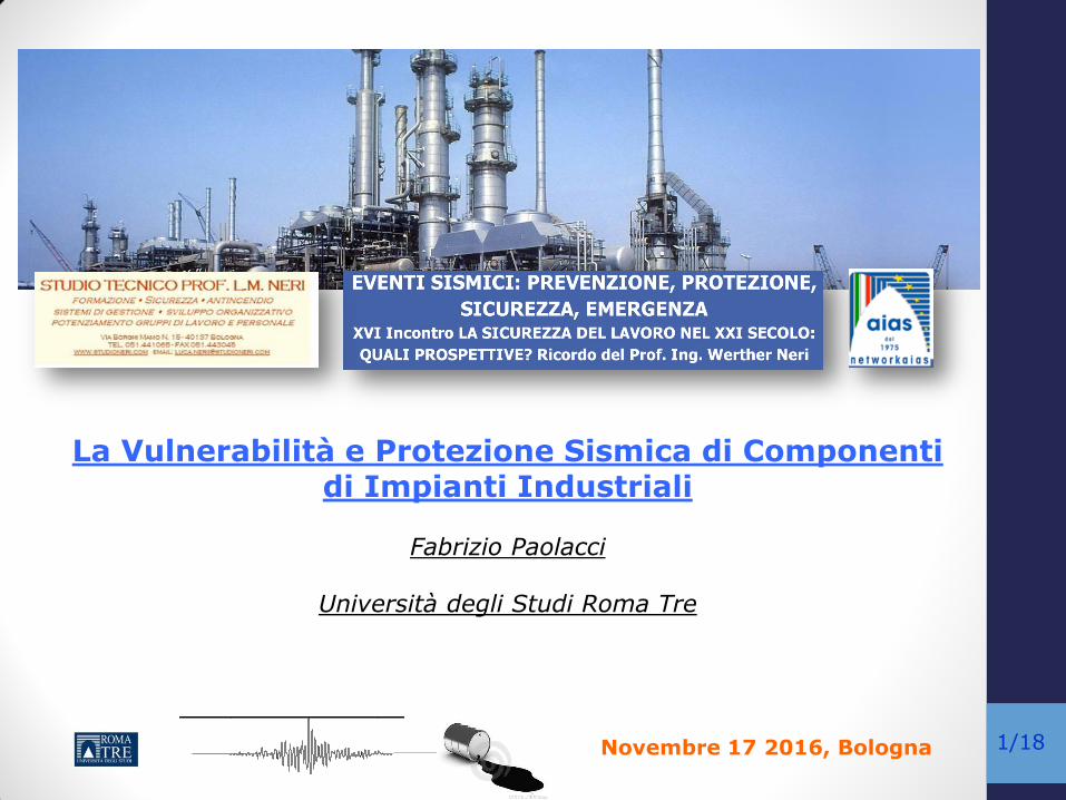
La Vulnerabilità e Protezione Sismica di Componenti di Impianti Industriali
Fabrizio Paolacci
Università degli Studi Roma Tre

Novembre 17 2016, Bologna
kc1
kc2
ki1
ki2
(a) (b)
mc1
mc2
mi1
mi2
mi
mc1
mi
kc1
ki1
mc2kc2
kc1
kc2
ki1
ki2
(a) (b)
mc1
mc2
mi1
mi2
mi
mc1
mi
kc1
ki1
mc2kc2
mc1
mi
kc1
ki1
ci
cckiso
ciso
mc1
mi
kc1
ki1
ci
cckiso
ciso
(c)2/18
Outline
Introduction
Definition of the problem
Structural classification of Industrial equipment and typical
damages under seismic action
Assessment methods for plant components: storage tanks
Example: Seismic assessment of an elevated tank
Example: Base Isolation of an elevated tank
kc1
kc2
ki1
ki2
(a) (b)
mc1
mc2
mi1
mi2
mi
mc1
mi
kc1
ki1
mc2kc2
kc1
kc2
ki1
ki2
(a) (b)
mc1
mc2
mi1
mi2
mi
mc1
mi
kc1
ki1
mc2kc2
mc1
mi
kc1
ki1
ci
cckiso
ciso
mc1
mi
kc1
ki1
ci
cckiso
ciso
(c)

Novembre 17 2016, Bologna
kc1
kc2
ki1
ki2
(a) (b)
mc1
mc2
mi1
mi2
mi
mc1
mi
kc1
ki1
mc2kc2
kc1
kc2
ki1
ki2
(a) (b)
mc1
mc2
mi1
mi2
mi
mc1
mi
kc1
ki1
mc2kc2
mc1
mi
kc1
ki1
ci
cckiso
ciso
mc1
mi
kc1
ki1
ci
cckiso
ciso
(c)3/18
Identification of the main industrial components (under structural point of view)
Collection into a limited number of classes based of geometrical and mechanical characteristics
Synthesis of the effects of earthquakes on the identified structural typologies of process components
Description of assessment methods for storage tanks
Analysis of a Case study
Applicability of base isolation of the seismic protection of storage tanks
Objectives
kc1
kc2
ki1
ki2
(a) (b)
mc1
mc2
mi1
mi2
mi
mc1
mi
kc1
ki1
mc2kc2
kc1
kc2
ki1
ki2
(a) (b)
mc1
mc2
mi1
mi2
mi
mc1
mi
kc1
ki1
mc2kc2
mc1
mi
kc1
ki1
ci
cckiso
ciso
mc1
mi
kc1
ki1
ci
cckiso
ciso
(c)

Novembre 17 2016, Bologna
kc1
kc2
ki1
ki2
(a) (b)
mc1
mc2
mi1
mi2
mi
mc1
mi
kc1
ki1
mc2kc2
kc1
kc2
ki1
ki2
(a) (b)
mc1
mc2
mi1
mi2
mi
mc1
mi
kc1
ki1
mc2kc2
mc1
mi
kc1
ki1
ci
cckiso
ciso
mc1
mi
kc1
ki1
ci
cckiso
ciso
(c)4/18
Definition of the problem
Among events that can cause serious accidents to industrial plants, seismic action (NATECH) must be potentially considered one of the most important. As a matter of fact, in Italy about 30% of industrial plants with major-accident hazards are located in areas with a high seismic risk.
In addition, in case of a seismic event, the earthquake can induces the simultaneous damage of more apparatus, which effects can result amplified because of the unsuccessful working of safety systems or because of the simultaneous generation of multiple accidental chains.
Novembre 17 2016, Bologna
kc1
kc2
ki1
ki2
(a) (b)
mc1
mc2
mi1
mi2
mi
mc1
mi
kc1
ki1
mc2kc2
kc1
kc2
ki1
ki2
(a) (b)
mc1
mc2
mi1
mi2
mi
mc1
mi
kc1
ki1
mc2kc2
mc1
mi
kc1
ki1
ci
cckiso
ciso
mc1
mi
kc1
ki1
ci
cckiso
ciso
(c)5/18
The usual safety requirements applied to civil buildings (ultimate and serviceability limit states) are generally unsuitable for structures of industrial plants.
As a matter of fact, a critical damage for a process safety that can cause an even modest release of inflammable substances, such as opening a flange or breaking a welding, or the simple friction between floating roof and tanks can result unessential from the structural damage point of view, but, at the same time, can cause considerable accidental chains.
kc1
kc2
ki1
ki2
(a) (b)
mc1
mc2
mi1
mi2
mi
mc1
mi
kc1
ki1
mc2kc2
kc1
kc2
ki1
ki2
(a) (b)
mc1
mc2
mi1
mi2
mi
mc1
mi
kc1
ki1
mc2kc2
mc1
mi
kc1
ki1
ci
cckiso
ciso
mc1
mi
kc1
ki1
ci
cckiso
ciso
(c)
Definition of the problem

Novembre 17 2016, Bologna
kc1
kc2
ki1
ki2
(a) (b)
mc1
mc2
mi1
mi2
mi
mc1
mi
kc1
ki1
mc2kc2
kc1
kc2
ki1
ki2
(a) (b)
mc1
mc2
mi1
mi2
mi
mc1
mi
kc1
ki1
mc2kc2
mc1
mi
kc1
ki1
ci
cckiso
ciso
mc1
mi
kc1
ki1
ci
cckiso
ciso
(c)6/18
Definition of the problem
Earthquake Data Magnitude
Anchorage (Alaska) March, 27th, 1964 8.6
Nigata (Japan) June, 16th, 1964 7.6
Valparaiso (Chile) March, 3rd 1985 7.8
Loma Prieta (California, USA) October,17th 1989 6.9
Costa Rica April, 22th 1991 7.6
Kobe (Japan) January, 17,1996 6.7
Kocaeli (Izmit, Turky) August, 17th 1999 7.6
Bhuj (Gujarat, India) January, 26th 2001 7.7
Tokachi-Oki (Japan) September, 26th, 2003 8.3
Major events that caused accidents to Industrial plants (from certified databases MARS, MHIDAS,EPA) are reported below
ALASKA, 1964 NIGATA, 1964 KOBE, 1995
ITZMIT, 1999
kc1
kc2
ki1
ki2
(a) (b)
mc1
mc2
mi1
mi2
mi
mc1
mi
kc1
ki1
mc2kc2
kc1
kc2
ki1
ki2
(a) (b)
mc1
mc2
mi1
mi2
mi
mc1
mi
kc1
ki1
mc2kc2
mc1
mi
kc1
ki1
ci
cckiso
ciso
mc1
mi
kc1
ki1
ci
cckiso
ciso
(c)
Tohoku, 2011

Novembre 17 2016, Bologna
kc1
kc2
ki1
ki2
(a) (b)
mc1
mc2
mi1
mi2
mi
mc1
mi
kc1
ki1
mc2kc2
kc1
kc2
ki1
ki2
(a) (b)
mc1
mc2
mi1
mi2
mi
mc1
mi
kc1
ki1
mc2kc2
mc1
mi
kc1
ki1
ci
cckiso
ciso
mc1
mi
kc1
ki1
ci
cckiso
ciso
(c)7/18
Definition of the problem
Major Hazard industrial plants in Italy N° impianti
tot.
N° impianti in
zona sismica
N° impianti in
I cat.
N° impianti in
II cat.
N° impianti in
III cat.
% impianti in
zona sismica REGIONE art. 6 art. 8 art. 6 art. 8 art. 6 art. 8 art. 6 art. 8 art. 6 art. 8 art. 6 art. 8
ABRUZZO 12 8 5 3 -- -- 5 3 -- -- 41,7% 37,5%
BASILICATA 4 2 3 1 -- 1 3 -- -- -- 75% 50%
CALABRIA 5 6 5 6 3 3 2 3 -- -- 100% 100%
CAMPANIA 44 28 40 27 -- -- 19 5 21 22 90,9% 96,4%
EMILIA-ROMAGNA 66 46 18 2 -- -- 18 2 -- -- 27,3% 4,3%
FRIULI-VEN.GIULIA 20 11 12 3 4 2 8 1 -- -- 60% 27,3%
LAZIO 44 35 24 13 -- -- 24 13 -- -- 54,5% 37,1%
LIGURIA 17 16 2 2 -- -- 2 2 -- -- 11,8% 12,5%
LOMBARDIA 144 113 1 1 -- -- 1 1 -- -- 0,7% 0,9%
MARCHE 8 7 8 7 -- -- 8 7 -- -- 100% 100%
MOLISE 3 4 1 1 -- -- 1 1 -- -- 33,3% 25%
PIEMONTE 80 38 -- 1 -- -- -- 1 -- -- -- 2,6%
PUGLIA 26 24 9 6 -- -- 6 6 3 -- 34,6% 25%
SARDEGNA 22 28 -- -- -- -- -- -- -- -- -- --
SICILIA 33 34 32 33 -- -- 32 33 -- -- 97% 97,1%
TOSCANA 42 19 28 11 -- -- 28 11 -- -- 66,7% 57,9%
TRENTINO-ALTO ADIGE 12 8 -- -- -- -- -- -- -- -- -- --
UMBRIA 14 4 11 3 -- -- 11 3 -- -- 78,6% 75%
VAL D'AOSTA 2 2 -- -- -- -- -- -- -- -- -- --
VENETO 51 40 3 -- -- -- 3 -- -- -- 5,9% --
ITALIA 649 473 202 120 7 6 172 92 24 22 31,1% 25,4%
D. Lgs. 334/99 (Seveso II), Direttiva 96/82/CE

Novembre 17 2016, Bologna
kc1
kc2
ki1
ki2
(a) (b)
mc1
mc2
mi1
mi2
mi
mc1
mi
kc1
ki1
mc2kc2
kc1
kc2
ki1
ki2
(a) (b)
mc1
mc2
mi1
mi2
mi
mc1
mi
kc1
ki1
mc2kc2
mc1
mi
kc1
ki1
ci
cckiso
ciso
mc1
mi
kc1
ki1
ci
cckiso
ciso
(c)8/18
Definition of the problem
Refinery plants in Europe

Novembre 17 2016, Bologna
kc1
kc2
ki1
ki2
(a) (b)
mc1
mc2
mi1
mi2
mi
mc1
mi
kc1
ki1
mc2kc2
kc1
kc2
ki1
ki2
(a) (b)
mc1
mc2
mi1
mi2
mi
mc1
mi
kc1
ki1
mc2kc2
mc1
mi
kc1
ki1
ci
cckiso
ciso
mc1
mi
kc1
ki1
ci
cckiso
ciso
(c)9/18
Equipment of a petrochemical plant
General view of a Petrochemical plant
Process flow of a Petrochemichal plant (Moulein & Makkee, 1987)
kc1
kc2
ki1
ki2
(a) (b)
mc1
mc2
mi1
mi2
mi
mc1
mi
kc1
ki1
mc2kc2
kc1
kc2
ki1
ki2
(a) (b)
mc1
mc2
mi1
mi2
mi
mc1
mi
kc1
ki1
mc2kc2
mc1
mi
kc1
ki1
ci
cckiso
ciso
mc1
mi
kc1
ki1
ci
cckiso
ciso
(c)

Novembre 17 2016, Bologna
kc1
kc2
ki1
ki2
(a) (b)
mc1
mc2
mi1
mi2
mi
mc1
mi
kc1
ki1
mc2kc2
kc1
kc2
ki1
ki2
(a) (b)
mc1
mc2
mi1
mi2
mi
mc1
mi
kc1
ki1
mc2kc2
mc1
mi
kc1
ki1
ci
cckiso
ciso
mc1
mi
kc1
ki1
ci
cckiso
ciso
(c)10/18
Equipment of a petrochemical plant
kc1
kc2
ki1
ki2
(a) (b)
mc1
mc2
mi1
mi2
mi
mc1
mi
kc1
ki1
mc2kc2
kc1
kc2
ki1
ki2
(a) (b)
mc1
mc2
mi1
mi2
mi
mc1
mi
kc1
ki1
mc2kc2
mc1
mi
kc1
ki1
ci
cckiso
ciso
mc1
mi
kc1
ki1
ci
cckiso
ciso
(c)
Typical layout of a Petroleum Refinery

Novembre 17 2016, Bologna
kc1
kc2
ki1
ki2
(a) (b)
mc1
mc2
mi1
mi2
mi
mc1
mi
kc1
ki1
mc2kc2
kc1
kc2
ki1
ki2
(a) (b)
mc1
mc2
mi1
mi2
mi
mc1
mi
kc1
ki1
mc2kc2
mc1
mi
kc1
ki1
ci
cckiso
ciso
mc1
mi
kc1
ki1
ci
cckiso
ciso
(c)11/18
kc1
kc2
ki1
ki2
(a) (b)
mc1
mc2
mi1
mi2
mi
mc1
mi
kc1
ki1
mc2kc2
kc1
kc2
ki1
ki2
(a) (b)
mc1
mc2
mi1
mi2
mi
mc1
mi
kc1
ki1
mc2kc2
mc1
mi
kc1
ki1
ci
cckiso
ciso
mc1
mi
kc1
ki1
ci
cckiso
ciso
(c)
Equipment of a petrochemical plant
Main components of a Petroleum refinery
A
B
C
D
Storage
Tanks A B Process Equipment
C Torches and flares D
Pipelines
Novembre 17 2016, Bologna
kc1
kc2
ki1
ki2
(a) (b)
mc1
mc2
mi1
mi2
mi
mc1
mi
kc1
ki1
mc2kc2
kc1
kc2
ki1
ki2
(a) (b)
mc1
mc2
mi1
mi2
mi
mc1
mi
kc1
ki1
mc2kc2
mc1
mi
kc1
ki1
ci
cckiso
ciso
mc1
mi
kc1
ki1
ci
cckiso
ciso
(c)12/18
Structural classification and typical seismic damages
Slim vessels
Squat equipment directly placed on the foundation
Squat equipment supported by columns
Piping, pipelines and supporting structures
kc1
kc2
ki1
ki2
(a) (b)
mc1
mc2
mi1
mi2
mi
mc1
mi
kc1
ki1
mc2kc2
kc1
kc2
ki1
ki2
(a) (b)
mc1
mc2
mi1
mi2
mi
mc1
mi
kc1
ki1
mc2kc2
mc1
mi
kc1
ki1
ci
cckiso
ciso
mc1
mi
kc1
ki1
ci
cckiso
ciso
(c)
F. Paolacci, R. Giannini, M. De Angelis, (2013), Seismic response mitigation of chemical plant components by passive control systems, Journal of Loss Prevention in Process Industries, Volume 26, Issue 5, Pages 879-948 Special Issue: Process Safety and Globalization - DOI:10.1016/j.jlp.2013.03.003.

Novembre 17 2016, Bologna
kc1
kc2
ki1
ki2
(a) (b)
mc1
mc2
mi1
mi2
mi
mc1
mi
kc1
ki1
mc2kc2
kc1
kc2
ki1
ki2
(a) (b)
mc1
mc2
mi1
mi2
mi
mc1
mi
kc1
ki1
mc2kc2
mc1
mi
kc1
ki1
ci
cckiso
ciso
mc1
mi
kc1
ki1
ci
cckiso
ciso
(c)13/18
Structural classification: SLIM VESSELS
Stacks, Torches Flares
Distillation columns and reactors
Horizontal cylindrical vessels

Novembre 17 2016, Bologna
kc1
kc2
ki1
ki2
(a) (b)
mc1
mc2
mi1
mi2
mi
mc1
mi
kc1
ki1
mc2kc2
kc1
kc2
ki1
ki2
(a) (b)
mc1
mc2
mi1
mi2
mi
mc1
mi
kc1
ki1
mc2kc2
mc1
mi
kc1
ki1
ci
cckiso
ciso
mc1
mi
kc1
ki1
ci
cckiso
ciso
(c)14/18
Structural classification: SLIM VESSELS (typical damages)
the most frequent damages in case of seismic event are the anchor bolts failure at the foundation due to the excessive actions, and the loss of contained fluids because of the failure of connected flanges due to excessive relative displacements.
Eccessive anchor bolt deformation
in a processing tower
Failure of a stack, Itzmit 1999
kc1
kc2
ki1
ki2
(a) (b)
mc1
mc2
mi1
mi2
mi
mc1
mi
kc1
ki1
mc2kc2
kc1
kc2
ki1
ki2
(a) (b)
mc1
mc2
mi1
mi2
mi
mc1
mi
kc1
ki1
mc2kc2
mc1
mi
kc1
ki1
ci
cckiso
ciso
mc1
mi
kc1
ki1
ci
cckiso
ciso
(c)April 19-20, 2010, Rome

Novembre 17 2016, Bologna
kc1
kc2
ki1
ki2
(a) (b)
mc1
mc2
mi1
mi2
mi
mc1
mi
kc1
ki1
mc2kc2
kc1
kc2
ki1
ki2
(a) (b)
mc1
mc2
mi1
mi2
mi
mc1
mi
kc1
ki1
mc2kc2
mc1
mi
kc1
ki1
ci
cckiso
ciso
mc1
mi
kc1
ki1
ci
cckiso
ciso
(c)15/18
Structural classification: Squat eq. directly placed on the foundation
These apparatus are characterized by heavy masses;
the main category of structures belonging to this group is the large cylindrical steel storage tanks with a height/diameter ratio between 0.2 and 2. The roof can be welded to the shell (fixed conic roof) or floating over the contained liquid. The operating volume varies from some tens to 200000 m3. kc1
kc2
ki1
ki2
(a) (b)
mc1
mc2
mi1
mi2
mi
mc1
mi
kc1
ki1
mc2kc2
kc1
kc2
ki1
ki2
(a) (b)
mc1
mc2
mi1
mi2
mi
mc1
mi
kc1
ki1
mc2kc2
mc1
mi
kc1
ki1
ci
cckiso
ciso
mc1
mi
kc1
ki1
ci
cckiso
ciso
(c)

Novembre 17 2016, Bologna
kc1
kc2
ki1
ki2
(a) (b)
mc1
mc2
mi1
mi2
mi
mc1
mi
kc1
ki1
mc2kc2
kc1
kc2
ki1
ki2
(a) (b)
mc1
mc2
mi1
mi2
mi
mc1
mi
kc1
ki1
mc2kc2
mc1
mi
kc1
ki1
ci
cckiso
ciso
mc1
mi
kc1
ki1
ci
cckiso
ciso
(c)16/18
16/29
The typical damages associated to these structures are related to buckling phenomena of the wall (elephant foot buckling, sloshing buckling) or to failure of the tank bottom-wall joint.
Other damages are possible, especially due to excessive sloshing motion, even in presence of a floating roof, which can cause liquid overtopping and fire due to the crash between roof and wall.
Uplift phenomenon is also possible
Elefant Foot Buckling
Elastic Buckling
Overtopping
(possible damages due to floating roof sloshing, Tokachi-oki 2003)
Torch fire
Sinking of F.R.
kc1
kc2
ki1
ki2
(a) (b)
mc1
mc2
mi1
mi2
mi
mc1
mi
kc1
ki1
mc2kc2
kc1
kc2
ki1
ki2
(a) (b)
mc1
mc2
mi1
mi2
mi
mc1
mi
kc1
ki1
mc2kc2
mc1
mi
kc1
ki1
ci
cckiso
ciso
mc1
mi
kc1
ki1
ci
cckiso
ciso
(c)
Structural classification: Squat eq. directly placed on the foundation (Typical damages)

Novembre 17 2016, Bologna
kc1
kc2
ki1
ki2
(a) (b)
mc1
mc2
mi1
mi2
mi
mc1
mi
kc1
ki1
mc2kc2
kc1
kc2
ki1
ki2
(a) (b)
mc1
mc2
mi1
mi2
mi
mc1
mi
kc1
ki1
mc2kc2
mc1
mi
kc1
ki1
ci
cckiso
ciso
mc1
mi
kc1
ki1
ci
cckiso
ciso
(c)17/18
Structural classification: Squat eq. supported by columns
Cylindrical elevated
tanks
Spherical storage vessels
Cylindrical or Cathedral-type Heaters

Novembre 17 2016, Bologna
kc1
kc2
ki1
ki2
(a) (b)
mc1
mc2
mi1
mi2
mi
mc1
mi
kc1
ki1
mc2kc2
kc1
kc2
ki1
ki2
(a) (b)
mc1
mc2
mi1
mi2
mi
mc1
mi
kc1
ki1
mc2kc2
mc1
mi
kc1
ki1
ci
cckiso
ciso
mc1
mi
kc1
ki1
ci
cckiso
ciso
(c)18/18
Structural classification: Squat eq. supported by columns (typical damages)
Soft-storey mechanism, especially in presence of short r.c columns (Itzmit,1999)
Fire due to the disconnection of the pipes-tanks joints kc1
kc2
ki1
ki2
(a) (b)
mc1
mc2
mi1
mi2
mi
mc1
mi
kc1
ki1
mc2kc2
kc1
kc2
ki1
ki2
(a) (b)
mc1
mc2
mi1
mi2
mi
mc1
mi
kc1
ki1
mc2kc2
mc1
mi
kc1
ki1
ci
cckiso
ciso
mc1
mi
kc1
ki1
ci
cckiso
ciso
(c)

Novembre 17 2016, Bologna
kc1
kc2
ki1
ki2
(a) (b)
mc1
mc2
mi1
mi2
mi
mc1
mi
kc1
ki1
mc2kc2
kc1
kc2
ki1
ki2
(a) (b)
mc1
mc2
mi1
mi2
mi
mc1
mi
kc1
ki1
mc2kc2
mc1
mi
kc1
ki1
ci
cckiso
ciso
mc1
mi
kc1
ki1
ci
cckiso
ciso
(c)19/18
Structural classification: Pipes, pipelines and support structure
Pipelines connect all equipment involved in the process, transferring the fluids within the plants
In a large refinery, hundreds kilometers of pipe-ways of different size are installed, and they are mainly realized with steel, but in some cases also with ceramics, glass, concrete, etc.
Metallic pipes themselves are not particularly vulnerable to seismic actions, but they can suffer the effects of differential displacements, which could be not compatible with the pipes deformations. They can also be damaged because of the collapse of the supporting structures,
Typical Layout
Damage of pipelines and support structure (Loma prieta)
kc1
kc2
ki1
ki2
(a) (b)
mc1
mc2
mi1
mi2
mi
mc1
mi
kc1
ki1
mc2kc2
kc1
kc2
ki1
ki2
(a) (b)
mc1
mc2
mi1
mi2
mi
mc1
mi
kc1
ki1
mc2kc2
mc1
mi
kc1
ki1
ci
cckiso
ciso
mc1
mi
kc1
ki1
ci
cckiso
ciso
(c)

Novembre 17 2016, Bologna
kc1
kc2
ki1
ki2
(a) (b)
mc1
mc2
mi1
mi2
mi
mc1
mi
kc1
ki1
mc2kc2
kc1
kc2
ki1
ki2
(a) (b)
mc1
mc2
mi1
mi2
mi
mc1
mi
kc1
ki1
mc2kc2
mc1
mi
kc1
ki1
ci
cckiso
ciso
mc1
mi
kc1
ki1
ci
cckiso
ciso
(c)20/18
Structural classification: Pipes, pipelines and support structure
kc1
kc2
ki1
ki2
(a) (b)
mc1
mc2
mi1
mi2
mi
mc1
mi
kc1
ki1
mc2kc2
kc1
kc2
ki1
ki2
(a) (b)
mc1
mc2
mi1
mi2
mi
mc1
mi
kc1
ki1
mc2kc2
mc1
mi
kc1
ki1
ci
cckiso
ciso
mc1
mi
kc1
ki1
ci
cckiso
ciso
(c)
Flange Bolted Joints Elbows Tee-joints

Novembre 17 2016, Bologna
kc1
kc2
ki1
ki2
(a) (b)
mc1
mc2
mi1
mi2
mi
mc1
mi
kc1
ki1
mc2kc2
kc1
kc2
ki1
ki2
(a) (b)
mc1
mc2
mi1
mi2
mi
mc1
mi
kc1
ki1
mc2kc2
mc1
mi
kc1
ki1
ci
cckiso
ciso
mc1
mi
kc1
ki1
ci
cckiso
ciso
(c)21/18
Typological and damage-based classification of plant components
Novembre 17 2016, Bologna
kc1
kc2
ki1
ki2
(a) (b)
mc1
mc2
mi1
mi2
mi
mc1
mi
kc1
ki1
mc2kc2
kc1
kc2
ki1
ki2
(a) (b)
mc1
mc2
mi1
mi2
mi
mc1
mi
kc1
ki1
mc2kc2
mc1
mi
kc1
ki1
ci
cckiso
ciso
mc1
mi
kc1
ki1
ci
cckiso
ciso
(c)22/18
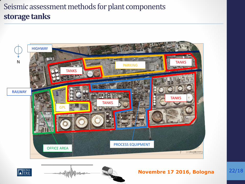
Seismic assessment methods for plant components storage tanks
TANKS
TANKS TANKS
TANKS
PROCESS EQUIPMENT
GPL
PARKING
OFFICE AREA
RAILWAY
HIGHWAY
N

Novembre 17 2016, Bologna
kc1
kc2
ki1
ki2
(a) (b)
mc1
mc2
mi1
mi2
mi
mc1
mi
kc1
ki1
mc2kc2
kc1
kc2
ki1
ki2
(a) (b)
mc1
mc2
mi1
mi2
mi
mc1
mi
kc1
ki1
mc2kc2
mc1
mi
kc1
ki1
ci
cckiso
ciso
mc1
mi
kc1
ki1
ci
cckiso
ciso
(c)23/18
Lim
it S
tate
s for
tanks
Typolo
gie
s o
f ta
nks
Seismic assessment methods for plant components storage tanks

Novembre 17 2016, Bologna
kc1
kc2
ki1
ki2
(a) (b)
mc1
mc2
mi1
mi2
mi
mc1
mi
kc1
ki1
mc2kc2
kc1
kc2
ki1
ki2
(a) (b)
mc1
mc2
mi1
mi2
mi
mc1
mi
kc1
ki1
mc2kc2
mc1
mi
kc1
ki1
ci
cckiso
ciso
mc1
mi
kc1
ki1
ci
cckiso
ciso
(c)24/18
The assessment of seismic vulnerability of storage tanks, is usually performed using the well-know concept of Fragility: the probability of exceeding of a certain limit state, P(D>LS| PGA). It is evaluated for different values of selected Intensity Measures. A suitable IM for tanks often adopted in literature is the PGA.
The main steps to evaluate fragility curves are the following:
• Definition of hazard and input signals
• Definition of Dynamic models
• Definition of Limit States
• Calculation of probability of failure
Seismic assessment methods for plant components storage tanks

Novembre 17 2016, Bologna
kc1
kc2
ki1
ki2
(a) (b)
mc1
mc2
mi1
mi2
mi
mc1
mi
kc1
ki1
mc2kc2
kc1
kc2
ki1
ki2
(a) (b)
mc1
mc2
mi1
mi2
mi
mc1
mi
kc1
ki1
mc2kc2
mc1
mi
kc1
ki1
ci
cckiso
ciso
mc1
mi
kc1
ki1
ci
cckiso
ciso
(c)25/18
Assessment methods for plant components: storage tanks 1. Seismic Hazard and input signals
0 0.5 1 1.5 2 2.5 3 3.5 40
0.2
0.4
0.6
0.8
1
1.2
1.4
1.6UHS
Period (sec)
Pg
a (
g)
5% in 200 years, Near Collapse LS
10% in 200 years, Life Safe LS
63% in 200 years, Damage LS
81% in 200 years, Operativity LS
1) 2)
3) 4)

Novembre 17 2016, Bologna
kc1
kc2
ki1
ki2
(a) (b)
mc1
mc2
mi1
mi2
mi
mc1
mi
kc1
ki1
mc2kc2
kc1
kc2
ki1
ki2
(a) (b)
mc1
mc2
mi1
mi2
mi
mc1
mi
kc1
ki1
mc2kc2
mc1
mi
kc1
ki1
ci
cckiso
ciso
mc1
mi
kc1
ki1
ci
cckiso
ciso
(c)26/18
Assessment methods for plant components: storage tanks 2. Dynamic modeling
Laplace Equation
• “Perfect Liquid “ (unviscous and uncompressible)
• Laminar and slow motion
• Free liquid surfaces
Hypotesis
gradv
IMPULSIVE MOTION
CONVECTIVE MOTION
ground motion
wr
FLUID-STRUCTUREINTERACTION
MOTION

Novembre 17 2016, Bologna
kc1
kc2
ki1
ki2
(a) (b)
mc1
mc2
mi1
mi2
mi
mc1
mi
kc1
ki1
mc2kc2
kc1
kc2
ki1
ki2
(a) (b)
mc1
mc2
mi1
mi2
mi
mc1
mi
kc1
ki1
mc2kc2
mc1
mi
kc1
ki1
ci
cckiso
ciso
mc1
mi
kc1
ki1
ci
cckiso
ciso
(c)27/18
Assessment methods for plant components: storage tanks 2. Dynamic modeling

Novembre 17 2016, Bologna
kc1
kc2
ki1
ki2
(a) (b)
mc1
mc2
mi1
mi2
mi
mc1
mi
kc1
ki1
mc2kc2
kc1
kc2
ki1
ki2
(a) (b)
mc1
mc2
mi1
mi2
mi
mc1
mi
kc1
ki1
mc2kc2
mc1
mi
kc1
ki1
ci
cckiso
ciso
mc1
mi
kc1
ki1
ci
cckiso
ciso
(c)28/18
Assessment methods for plant components: storage tanks 2. Dynamic modeling
kc1
kc2
ki1
ki2
(a) (b)
mc1
mc2
mi1
mi2
mi
mc1
mi
kc1
ki1
mc2kc2
kc1
kc2
ki1
ki2
(a) (b)
mc1
mc2
mi1
mi2
mi
mc1
mi
kc1
ki1
mc2kc2
mc1
mi
kc1
ki1
ci
cckiso
ciso
mc1
mi
kc1
ki1
ci
cckiso
ciso
(c)
Lumped mass models of tanks: (a) Slender, (b) Broad

Novembre 17 2016, Bologna
kc1
kc2
ki1
ki2
(a) (b)
mc1
mc2
mi1
mi2
mi
mc1
mi
kc1
ki1
mc2kc2
kc1
kc2
ki1
ki2
(a) (b)
mc1
mc2
mi1
mi2
mi
mc1
mi
kc1
ki1
mc2kc2
mc1
mi
kc1
ki1
ci
cckiso
ciso
mc1
mi
kc1
ki1
ci
cckiso
ciso
(c)29/18
Assessment methods for plant components: storage tanks 2. Dynamic modeling
Lumped mass models of elevated tanks
Novembre 17 2016, Bologna
kc1
kc2
ki1
ki2
(a) (b)
mc1
mc2
mi1
mi2
mi
mc1
mi
kc1
ki1
mc2kc2
kc1
kc2
ki1
ki2
(a) (b)
mc1
mc2
mi1
mi2
mi
mc1
mi
kc1
ki1
mc2kc2
mc1
mi
kc1
ki1
ci
cckiso
ciso
mc1
mi
kc1
ki1
ci
cckiso
ciso
(c)30/18
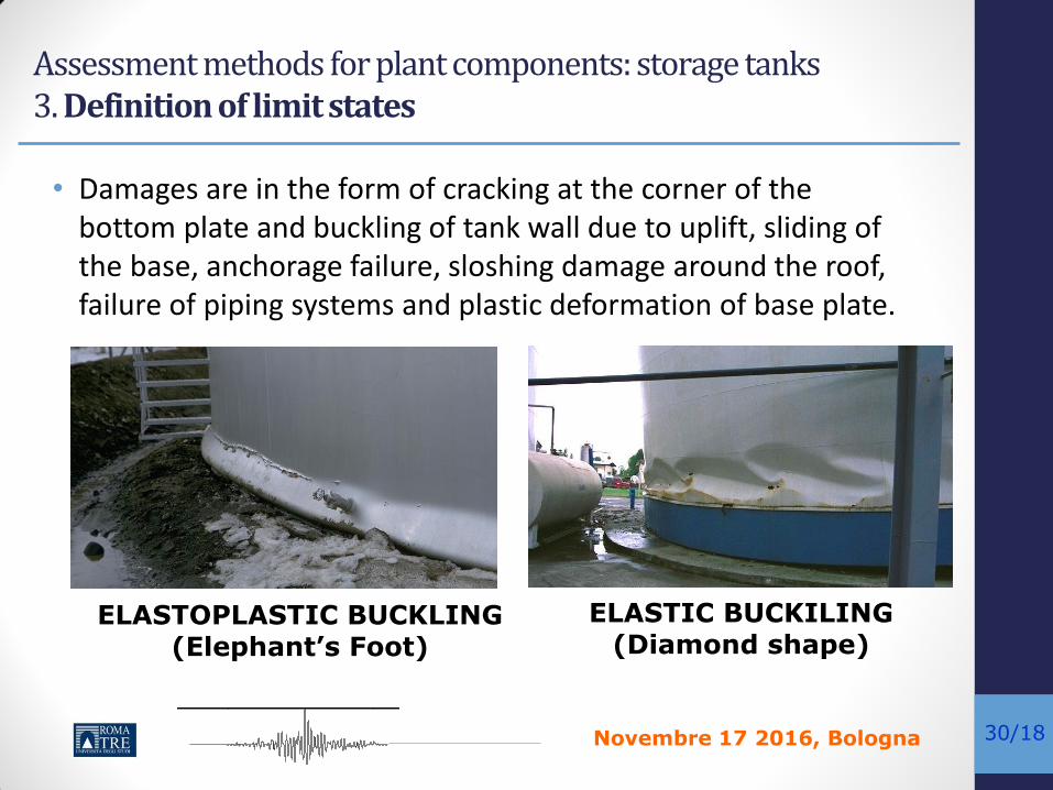
• Damages are in the form of cracking at the corner of the bottom plate and buckling of tank wall due to uplift, sliding of the base, anchorage failure, sloshing damage around the roof, failure of piping systems and plastic deformation of base plate.
ELASTOPLASTIC BUCKLING (Elephant’s Foot)
ELASTIC BUCKILING (Diamond shape)
Assessment methods for plant components: storage tanks 3. Definition of limit states

Novembre 17 2016, Bologna
kc1
kc2
ki1
ki2
(a) (b)
mc1
mc2
mi1
mi2
mi
mc1
mi
kc1
ki1
mc2kc2
kc1
kc2
ki1
ki2
(a) (b)
mc1
mc2
mi1
mi2
mi
mc1
mi
kc1
ki1
mc2kc2
mc1
mi
kc1
ki1
ci
cckiso
ciso
mc1
mi
kc1
ki1
ci
cckiso
ciso
(c)31/18
OVERTOPING UPLIFTING
Assessment methods for plant components: storage tanks 3. Definition of limit states

Novembre 17 2016, Bologna
kc1
kc2
ki1
ki2
(a) (b)
mc1
mc2
mi1
mi2
mi
mc1
mi
kc1
ki1
mc2kc2
kc1
kc2
ki1
ki2
(a) (b)
mc1
mc2
mi1
mi2
mi
mc1
mi
kc1
ki1
mc2kc2
mc1
mi
kc1
ki1
ci
cckiso
ciso
mc1
mi
kc1
ki1
ci
cckiso
ciso
(c)32/18
Assessment methods for plant components: storage tanks 3. Definition of limit states
Each Damage State can be quantified analytically using for example the analytical formula provided by the current regulations. Buckling problems have been well solved in literature whose solutions are included in most of the standards and codes. For example: Elephant foot buckling (EN1998:4)

Novembre 17 2016, Bologna
kc1
kc2
ki1
ki2
(a) (b)
mc1
mc2
mi1
mi2
mi
mc1
mi
kc1
ki1
mc2kc2
kc1
kc2
ki1
ki2
(a) (b)
mc1
mc2
mi1
mi2
mi
mc1
mi
kc1
ki1
mc2kc2
mc1
mi
kc1
ki1
ci
cckiso
ciso
mc1
mi
kc1
ki1
ci
cckiso
ciso
(c)33/18
• The structural fragility can be defined as the probability of exceeding a selected Limit State (LS) for a specified the Intensity Measure (IM).
• A lognormal cumulative distribution function is often used to define a fragility function:
ln /[ | ]EDP
IMP D LS IM
standard deviation of lnIM (dispersion of IM)
median of the fragility function
probability of exceeding a selected LS for a specified
IM
Assessment methods for plant components: storage tanks 4. Calculation of Fragility curves
Novembre 17 2016, Bologna
kc1
kc2
ki1
ki2
(a) (b)
mc1
mc2
mi1
mi2
mi
mc1
mi
kc1
ki1
mc2kc2
kc1
kc2
ki1
ki2
(a) (b)
mc1
mc2
mi1
mi2
mi
mc1
mi
kc1
ki1
mc2kc2
mc1
mi
kc1
ki1
ci
cckiso
ciso
mc1
mi
kc1
ki1
ci
cckiso
ciso
(c)34/18
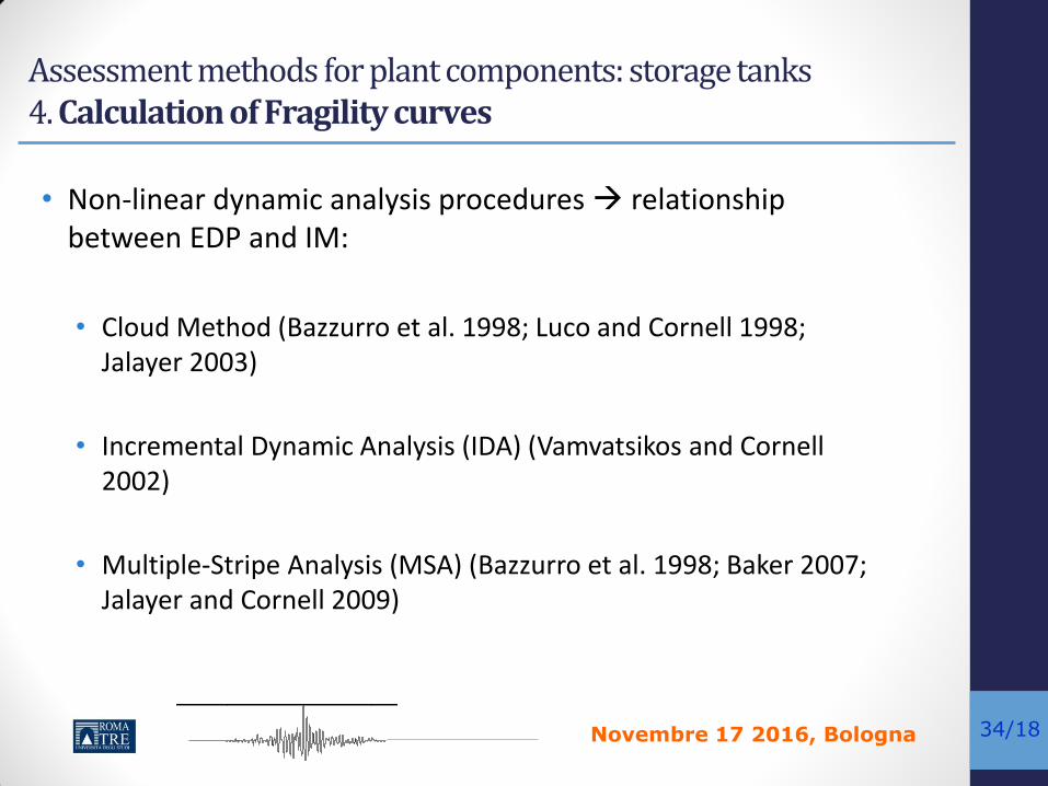
• Non-linear dynamic analysis procedures relationship between EDP and IM:
• Cloud Method (Bazzurro et al. 1998; Luco and Cornell 1998; Jalayer 2003)
• Incremental Dynamic Analysis (IDA) (Vamvatsikos and Cornell 2002)
• Multiple-Stripe Analysis (MSA) (Bazzurro et al. 1998; Baker 2007; Jalayer and Cornell 2009)
Assessment methods for plant components: storage tanks 4. Calculation of Fragility curves

Novembre 17 2016, Bologna
kc1
kc2
ki1
ki2
(a) (b)
mc1
mc2
mi1
mi2
mi
mc1
mi
kc1
ki1
mc2kc2
kc1
kc2
ki1
ki2
(a) (b)
mc1
mc2
mi1
mi2
mi
mc1
mi
kc1
ki1
mc2kc2
mc1
mi
kc1
ki1
ci
cckiso
ciso
mc1
mi
kc1
ki1
ci
cckiso
ciso
(c)35/18
• Cloud Analysis method uses a set of un-scaled ground motion records.
• This method implements the non-linear dynamic analysis results in a (linear) regression-based probabilistic model.
• Assumption of a constant conditional standard deviation for probability distribution of the EDP given IM.
• Strong dependence on the suite of ground motion records.
Assessment methods for plant components: storage tanks 4. Calculation of Fragility curves: Cloud Analysis

Novembre 17 2016, Bologna
kc1
kc2
ki1
ki2
(a) (b)
mc1
mc2
mi1
mi2
mi
mc1
mi
kc1
ki1
mc2kc2
kc1
kc2
ki1
ki2
(a) (b)
mc1
mc2
mi1
mi2
mi
mc1
mi
kc1
ki1
mc2kc2
mc1
mi
kc1
ki1
ci
cckiso
ciso
mc1
mi
kc1
ki1
ci
cckiso
ciso
(c)36/18
Example: Cloud Analysis results
ln(IM=PGA)
ln(DEDP)
Each point represents the peak value of DEDP in the
term of PGA
Linear regression analysis
lnDEDP = alnPGAb
Assessment methods for plant components: storage tanks 4. Calculation of Fragility curves: Cloud Analysis
b
mD a IM
a and b are regression coefficients based on the collection of di and IMi .
2
1|
ln ln
2
nb
i ii
d IM
d aIM
n
Dispersion
mean

Novembre 17 2016, Bologna
kc1
kc2
ki1
ki2
(a) (b)
mc1
mc2
mi1
mi2
mi
mc1
mi
kc1
ki1
mc2kc2
kc1
kc2
ki1
ki2
(a) (b)
mc1
mc2
mi1
mi2
mi
mc1
mi
kc1
ki1
mc2kc2
mc1
mi
kc1
ki1
ci
cckiso
ciso
mc1
mi
kc1
ki1
ci
cckiso
ciso
(c)37/18
• When the seismic demands and the structural limit states are assumed to follow a lognormal distribution, the probability of exceeding a specific damage state can be given as:
standard normal cumulative distribution function
LSm median estimate of the structural limit state
Dm median estimate of the demand
βd|IM dispersion of the demand conditioned on the IM
βLS dispersion of the structural limit state
2 2|
ln ln| 1
m m
EDP
LSd IM
LS DP D LS IM
Assessment methods for plant components: storage tanks 4. Calculation of Fragility curves : Cloud Analysis

Novembre 17 2016, Bologna
kc1
kc2
ki1
ki2
(a) (b)
mc1
mc2
mi1
mi2
mi
mc1
mi
kc1
ki1
mc2kc2
kc1
kc2
ki1
ki2
(a) (b)
mc1
mc2
mi1
mi2
mi
mc1
mi
kc1
ki1
mc2kc2
mc1
mi
kc1
ki1
ci
cckiso
ciso
mc1
mi
kc1
ki1
ci
cckiso
ciso
(c)38/18
Assessment methods for plant components: storage tanks Example: Fragility curves evaluation of an LNG tank
Storage tanks of Liquid Oxygen at Habas plant after the strong event
of Itzmit (1999)

Novembre 17 2016, Bologna
kc1
kc2
ki1
ki2
(a) (b)
mc1
mc2
mi1
mi2
mi
mc1
mi
kc1
ki1
mc2kc2
kc1
kc2
ki1
ki2
(a) (b)
mc1
mc2
mi1
mi2
mi
mc1
mi
kc1
ki1
mc2kc2
mc1
mi
kc1
ki1
ci
cckiso
ciso
mc1
mi
kc1
ki1
ci
cckiso
ciso
(c)39/18
• 3D nonlinear modeling
Sketch of 3D model (OPENSEES)
Liquid mass is lumped and subdivided into impulsive and convective masses.
RC columns are modeled using 3D nonlinear elements with fiber-
defined cross-sections
Assessment methods for plant components: storage tanks Example: Fragility curves evaluation of an LNG tank

Novembre 17 2016, Bologna
kc1
kc2
ki1
ki2
(a) (b)
mc1
mc2
mi1
mi2
mi
mc1
mi
kc1
ki1
mc2kc2
kc1
kc2
ki1
ki2
(a) (b)
mc1
mc2
mi1
mi2
mi
mc1
mi
kc1
ki1
mc2kc2
mc1
mi
kc1
ki1
ci
cckiso
ciso
mc1
mi
kc1
ki1
ci
cckiso
ciso
(c)40/18
• Columns with small aspect ratio or without adequate shear-resisting reinforcement, shear deformation governs the total response unexpected shear or shear-flexure failure.
The total lateral deformation of a fixed-ended RC column: flexural, reinforcement
slip, and shear deformations.
Assessment methods for plant components: storage tanks Example: Fragility curves evaluation of an LNG tank
Shear deformation
Sh
ear f
orce
Novembre 17 2016, Bologna
kc1
kc2
ki1
ki2
(a) (b)
mc1
mc2
mi1
mi2
mi
mc1
mi
kc1
ki1
mc2kc2
kc1
kc2
ki1
ki2
(a) (b)
mc1
mc2
mi1
mi2
mi
mc1
mi
kc1
ki1
mc2kc2
mc1
mi
kc1
ki1
ci
cckiso
ciso
mc1
mi
kc1
ki1
ci
cckiso
ciso
(c)41/18
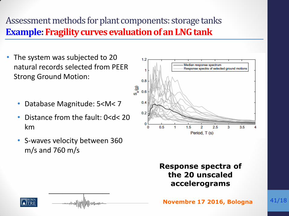
• The system was subjected to 20 natural records selected from PEER Strong Ground Motion:
• Database Magnitude: 5<M< 7
• Distance from the fault: 0<d< 20 km
• S-waves velocity between 360 m/s and 760 m/s
Response spectra of
the 20 unscaled accelerograms
Assessment methods for plant components: storage tanks Example: Fragility curves evaluation of an LNG tank

Novembre 17 2016, Bologna
kc1
kc2
ki1
ki2
(a) (b)
mc1
mc2
mi1
mi2
mi
mc1
mi
kc1
ki1
mc2kc2
kc1
kc2
ki1
ki2
(a) (b)
mc1
mc2
mi1
mi2
mi
mc1
mi
kc1
ki1
mc2kc2
mc1
mi
kc1
ki1
ci
cckiso
ciso
mc1
mi
kc1
ki1
ci
cckiso
ciso
(c)42/18
Assessment methods for plant components: storage tanks Example: Fragility curves evaluation of an LNG tank • EngineeringDemandParameters(EDP):
• Driftratio
• Compressivemeridional stress(API650)
• Elevationofliquidfreesurface(EN1998:4)
( ) 2
11 0.4 1.273 T
z t gvs
Mw a
t Ds
æ öç ÷è ø
= + +
colH
dq =
( )max 0.84 /a cd RS T g=

Novembre 17 2016, Bologna
kc1
kc2
ki1
ki2
(a) (b)
mc1
mc2
mi1
mi2
mi
mc1
mi
kc1
ki1
mc2kc2
kc1
kc2
ki1
ki2
(a) (b)
mc1
mc2
mi1
mi2
mi
mc1
mi
kc1
ki1
mc2kc2
mc1
mi
kc1
ki1
ci
cckiso
ciso
mc1
mi
kc1
ki1
ci
cckiso
ciso
(c)43/18
• Limit states: • Ultimate Drift ratio at pure-shear failure Drift ratio for pure flexural failure
(Chord Rotation)
• Meridional design buckling stress (EN 1998-4)
• Free board height:
LS tank liquid
d H H
1 1, ,/ /x yM Mx Rd x Rk
qLS
= 0.245% qLS
= 0.360%EN 1998-4
(*) M. Gerin and P. Adebar (2004) Accounting for Shear in Seismic Analysis of Concrete Structures 13th World Conference on Earthquake Engineering (WCEE), Vancouver, Canada, August 2004
(*)
Assessment methods for plant components: storage tanks Example: Fragility curves evaluation of an LNG tank

Novembre 17 2016, Bologna
kc1
kc2
ki1
ki2
(a) (b)
mc1
mc2
mi1
mi2
mi
mc1
mi
kc1
ki1
mc2kc2
kc1
kc2
ki1
ki2
(a) (b)
mc1
mc2
mi1
mi2
mi
mc1
mi
kc1
ki1
mc2kc2
mc1
mi
kc1
ki1
ci
cckiso
ciso
mc1
mi
kc1
ki1
ci
cckiso
ciso
(c)44/18
Assessment methods for plant components: storage tanks Example: Fragility curves evaluation of an LNG tank
Seismic Demand Parameters

Novembre 17 2016, Bologna
kc1
kc2
ki1
ki2
(a) (b)
mc1
mc2
mi1
mi2
mi
mc1
mi
kc1
ki1
mc2kc2
kc1
kc2
ki1
ki2
(a) (b)
mc1
mc2
mi1
mi2
mi
mc1
mi
kc1
ki1
mc2kc2
mc1
mi
kc1
ki1
ci
cckiso
ciso
mc1
mi
kc1
ki1
ci
cckiso
ciso
(c)45/18
Fragility curve for shear failure of
columns
Probabilistic Seismic Response Analysis (Cloud Analysis)
Assessment methods for plant components: storage tanks Example: Fragility curves evaluation of an LNG tank

Novembre 17 2016, Bologna
kc1
kc2
ki1
ki2
(a) (b)
mc1
mc2
mi1
mi2
mi
mc1
mi
kc1
ki1
mc2kc2
kc1
kc2
ki1
ki2
(a) (b)
mc1
mc2
mi1
mi2
mi
mc1
mi
kc1
ki1
mc2kc2
mc1
mi
kc1
ki1
ci
cckiso
ciso
mc1
mi
kc1
ki1
ci
cckiso
ciso
(c)46/18
Seismic protection of Industrial Components Passive Control Systems
Tecniche di Controllo passivo
Tecniche basate
sull’elongazione
del periodo
Tecniche basate
sull’incremento
artificiale dello
smorzamento
Isolamento alla base
Controventi
dissipativi
Masse
Accordate
(TMD)
Accoppiamento
dissispativo

Novembre 17 2016, Bologna
kc1
kc2
ki1
ki2
(a) (b)
mc1
mc2
mi1
mi2
mi
mc1
mi
kc1
ki1
mc2kc2
kc1
kc2
ki1
ki2
(a) (b)
mc1
mc2
mi1
mi2
mi
mc1
mi
kc1
ki1
mc2kc2
mc1
mi
kc1
ki1
ci
cckiso
ciso
mc1
mi
kc1
ki1
ci
cckiso
ciso
(c)47/18
Seismic protection of Industrial Components Passive Control Systems

Novembre 17 2016, Bologna
kc1
kc2
ki1
ki2
(a) (b)
mc1
mc2
mi1
mi2
mi
mc1
mi
kc1
ki1
mc2kc2
kc1
kc2
ki1
ki2
(a) (b)
mc1
mc2
mi1
mi2
mi
mc1
mi
kc1
ki1
mc2kc2
mc1
mi
kc1
ki1
ci
cckiso
ciso
mc1
mi
kc1
ki1
ci
cckiso
ciso
(c)48/18
Seismic protection of Industrial Components Passive Control Systems Principi di funzionamento dei SCP
Dolce ed al. “ progetti di edifici isolati alla base”, IUSS Press

Novembre 17 2016, Bologna
kc1
kc2
ki1
ki2
(a) (b)
mc1
mc2
mi1
mi2
mi
mc1
mi
kc1
ki1
mc2kc2
kc1
kc2
ki1
ki2
(a) (b)
mc1
mc2
mi1
mi2
mi
mc1
mi
kc1
ki1
mc2kc2
mc1
mi
kc1
ki1
ci
cckiso
ciso
mc1
mi
kc1
ki1
ci
cckiso
ciso
(c)49/18
Seismic protection of Industrial Components Passive Control Systems
Possible techniques…

Novembre 17 2016, Bologna
kc1
kc2
ki1
ki2
(a) (b)
mc1
mc2
mi1
mi2
mi
mc1
mi
kc1
ki1
mc2kc2
kc1
kc2
ki1
ki2
(a) (b)
mc1
mc2
mi1
mi2
mi
mc1
mi
kc1
ki1
mc2kc2
mc1
mi
kc1
ki1
ci
cckiso
ciso
mc1
mi
kc1
ki1
ci
cckiso
ciso
(c)50/18
Seismic protection of Industrial Components Passive Control Systems
POSSIBILI SISTEMI DI PROTEZIONE PASSIVA PER SERBATOI

Novembre 17 2016, Bologna
kc1
kc2
ki1
ki2
(a) (b)
mc1
mc2
mi1
mi2
mi
mc1
mi
kc1
ki1
mc2kc2
kc1
kc2
ki1
ki2
(a) (b)
mc1
mc2
mi1
mi2
mi
mc1
mi
kc1
ki1
mc2kc2
mc1
mi
kc1
ki1
ci
cckiso
ciso
mc1
mi
kc1
ki1
ci
cckiso
ciso
(c)51/18
Seismic protection of Industrial Components Passive Control Systems
Controventamento dissipativo
Dissipazione di energia (Curadelli 2011)

Novembre 17 2016, Bologna
kc1
kc2
ki1
ki2
(a) (b)
mc1
mc2
mi1
mi2
mi
mc1
mi
kc1
ki1
mc2kc2
kc1
kc2
ki1
ki2
(a) (b)
mc1
mc2
mi1
mi2
mi
mc1
mi
kc1
ki1
mc2kc2
mc1
mi
kc1
ki1
ci
cckiso
ciso
mc1
mi
kc1
ki1
ci
cckiso
ciso
(c)52/18
Seismic protection of Industrial Components Passive Control Systems Dissipazione di energia (Malhotra 1998)
N.B. Questa soluzione sfrutta il fenomeno dell’uplift,i cui spostamenti rispetto al terreno vengono sfruttati per attivare un meccanismo di dissipazione ad hoc

Novembre 17 2016, Bologna
kc1
kc2
ki1
ki2
(a) (b)
mc1
mc2
mi1
mi2
mi
mc1
mi
kc1
ki1
mc2kc2
kc1
kc2
ki1
ki2
(a) (b)
mc1
mc2
mi1
mi2
mi
mc1
mi
kc1
ki1
mc2kc2
mc1
mi
kc1
ki1
ci
cckiso
ciso
mc1
mi
kc1
ki1
ci
cckiso
ciso
(c)53/18
Seismic protection of Industrial Components Passive Control Systems Isolamento sismico (Malhotra 1997)
N.B. Questa soluzione ha il vantaggio di non dover realizzare una soletta rigida alla base

Novembre 17 2016, Bologna
kc1
kc2
ki1
ki2
(a) (b)
mc1
mc2
mi1
mi2
mi
mc1
mi
kc1
ki1
mc2kc2
kc1
kc2
ki1
ki2
(a) (b)
mc1
mc2
mi1
mi2
mi
mc1
mi
kc1
ki1
mc2kc2
mc1
mi
kc1
ki1
ci
cckiso
ciso
mc1
mi
kc1
ki1
ci
cckiso
ciso
(c)54/18
Seismic protection of Industrial Components Base Isolation
ISOLATORE ELASTOPLASTICO
Novembre 17 2016, Bologna
kc1
kc2
ki1
ki2
(a) (b)
mc1
mc2
mi1
mi2
mi
mc1
mi
kc1
ki1
mc2kc2
kc1
kc2
ki1
ki2
(a) (b)
mc1
mc2
mi1
mi2
mi
mc1
mi
kc1
ki1
mc2kc2
mc1
mi
kc1
ki1
ci
cckiso
ciso
mc1
mi
kc1
ki1
ci
cckiso
ciso
(c)55/18
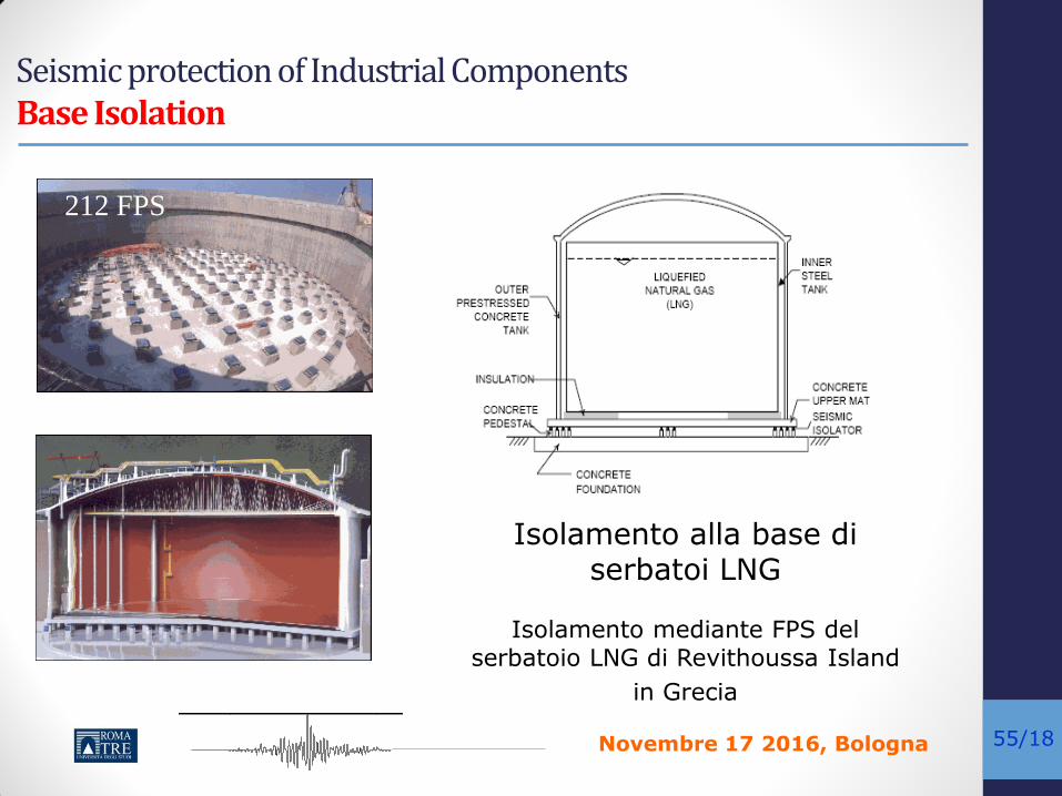
Seismic protection of Industrial Components Base Isolation
212 FPS
Isolamento alla base di serbatoi LNG
Isolamento mediante FPS del
serbatoio LNG di Revithoussa Island
in Grecia

Novembre 17 2016, Bologna
kc1
kc2
ki1
ki2
(a) (b)
mc1
mc2
mi1
mi2
mi
mc1
mi
kc1
ki1
mc2kc2
kc1
kc2
ki1
ki2
(a) (b)
mc1
mc2
mi1
mi2
mi
mc1
mi
kc1
ki1
mc2kc2
mc1
mi
kc1
ki1
ci
cckiso
ciso
mc1
mi
kc1
ki1
ci
cckiso
ciso
(c)56/18
Seismic protection of Industrial Components Base Isolation
Isolamento alla base di serbatoi LNG
Isolamento mediante FPS del serbatoio LNG a Melchorita in Perù
Novembre 17 2016, Bologna
kc1
kc2
ki1
ki2
(a) (b)
mc1
mc2
mi1
mi2
mi
mc1
mi
kc1
ki1
mc2kc2
kc1
kc2
ki1
ki2
(a) (b)
mc1
mc2
mi1
mi2
mi
mc1
mi
kc1
ki1
mc2kc2
mc1
mi
kc1
ki1
ci
cckiso
ciso
mc1
mi
kc1
ki1
ci
cckiso
ciso
(c)57/18
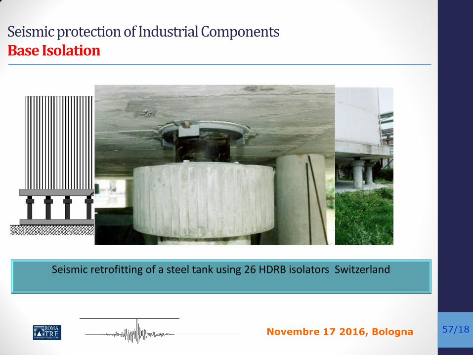
Seismic protection of Industrial Components Base Isolation
Seismic retrofitting of a steel tank using 26 HDRB isolators Switzerland

Novembre 17 2016, Bologna
kc1
kc2
ki1
ki2
(a) (b)
mc1
mc2
mi1
mi2
mi
mc1
mi
kc1
ki1
mc2kc2
kc1
kc2
ki1
ki2
(a) (b)
mc1
mc2
mi1
mi2
mi
mc1
mi
kc1
ki1
mc2kc2
mc1
mi
kc1
ki1
ci
cckiso
ciso
mc1
mi
kc1
ki1
ci
cckiso
ciso
(c)58/18
Seismic protection of Industrial Components Base Isolation
Seismic retrofitting of a steel tank using FPS Petrolchimical pole of Siracusa
Priolo Gargallo (Sr) – Sicily

Novembre 17 2016, Bologna
kc1
kc2
ki1
ki2
(a) (b)
mc1
mc2
mi1
mi2
mi
mc1
mi
kc1
ki1
mc2kc2
kc1
kc2
ki1
ki2
(a) (b)
mc1
mc2
mi1
mi2
mi
mc1
mi
kc1
ki1
mc2kc2
mc1
mi
kc1
ki1
ci
cckiso
ciso
mc1
mi
kc1
ki1
ci
cckiso
ciso
(c)59/18
Seismic protection of Industrial Components Base Isolation Quali tipi di isolatori utilizzare?

Novembre 17 2016, Bologna
kc1
kc2
ki1
ki2
(a) (b)
mc1
mc2
mi1
mi2
mi
mc1
mi
kc1
ki1
mc2kc2
kc1
kc2
ki1
ki2
(a) (b)
mc1
mc2
mi1
mi2
mi
mc1
mi
kc1
ki1
mc2kc2
mc1
mi
kc1
ki1
ci
cckiso
ciso
mc1
mi
kc1
ki1
ci
cckiso
ciso
(c)60/18
Seismic protection of Industrial Components Base Isolation
Si può utilizzare il modello a pochi gradi di libertà
Il comportamento non lineare dei dispositivi di isolamento può
essere agevolmente implementato
Per una progetto di prima approssimazione si può ipotizzare che la
massa isolata sia solo quella impulsiva, essendo quella convettiva già
naturalmente isolatata avendo un periodo molto elevato.
Di conseguenza la rigidezza del sistema di isolamento può essere
facilmente ricavata dalla relazione seguente
Periodo del serbatoio isolato
Modello di calcolo del serbatoio isolato alla base
Novembre 17 2016, Bologna
kc1
kc2
ki1
ki2
(a) (b)
mc1
mc2
mi1
mi2
mi
mc1
mi
kc1
ki1
mc2kc2
kc1
kc2
ki1
ki2
(a) (b)
mc1
mc2
mi1
mi2
mi
mc1
mi
kc1
ki1
mc2kc2
mc1
mi
kc1
ki1
ci
cckiso
ciso
mc1
mi
kc1
ki1
ci
cckiso
ciso
(c)61/18
Seismic protection of Industrial Components Base Isolation
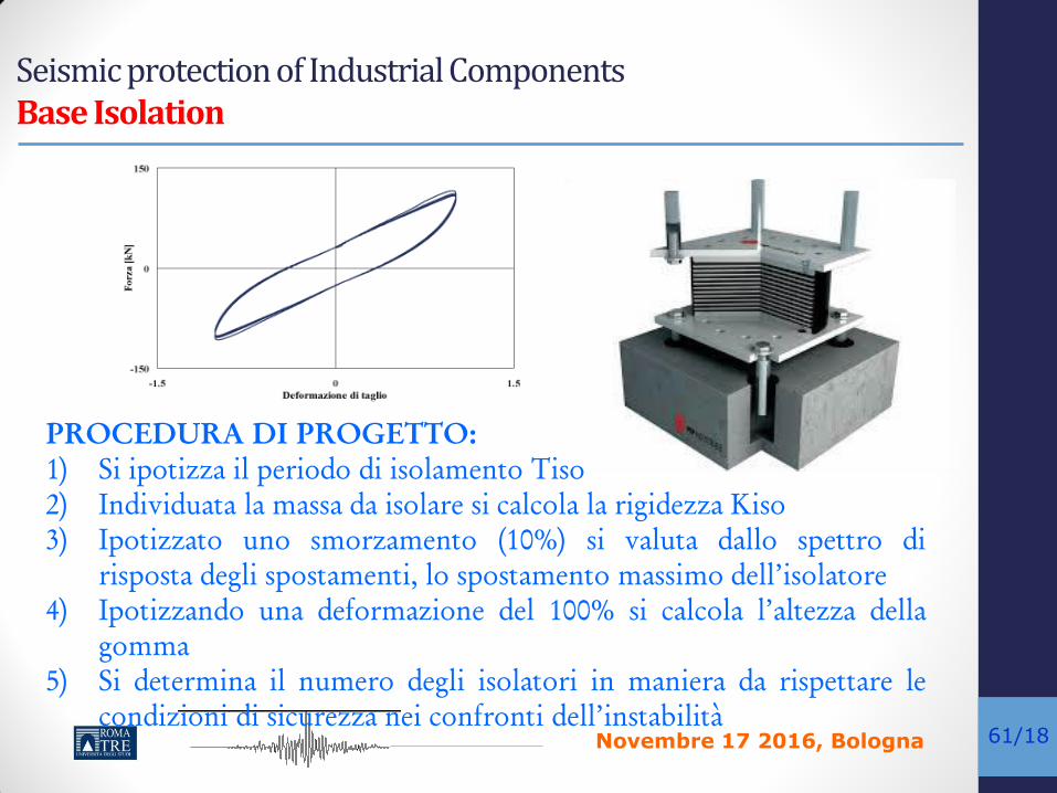
PROCEDURA DI PROGETTO:
1) Si ipotizza il periodo di isolamento Tiso
2) Individuata la massa da isolare si calcola la rigidezza Kiso
3) Ipotizzato uno smorzamento (10%) si valuta dallo spettro di
risposta degli spostamenti, lo spostamento massimo dell’isolatore
4) Ipotizzando una deformazione del 100% si calcola l’altezza della
gomma
5) Si determina il numero degli isolatori in maniera da rispettare le
condizioni di sicurezza nei confronti dell’instabilità

Novembre 17 2016, Bologna
kc1
kc2
ki1
ki2
(a) (b)
mc1
mc2
mi1
mi2
mi
mc1
mi
kc1
ki1
mc2kc2
kc1
kc2
ki1
ki2
(a) (b)
mc1
mc2
mi1
mi2
mi
mc1
mi
kc1
ki1
mc2kc2
mc1
mi
kc1
ki1
ci
cckiso
ciso
mc1
mi
kc1
ki1
ci
cckiso
ciso
(c)62/18
Seismic protection of Industrial Components Base Isolation
N/R
μN
X
Vibration Period of base-isolated structure with FPS
Vibration Period of base-isolated Tank with FPS
Ke

Novembre 17 2016, Bologna
kc1
kc2
ki1
ki2
(a) (b)
mc1
mc2
mi1
mi2
mi
mc1
mi
kc1
ki1
mc2kc2
kc1
kc2
ki1
ki2
(a) (b)
mc1
mc2
mi1
mi2
mi
mc1
mi
kc1
ki1
mc2kc2
mc1
mi
kc1
ki1
ci
cckiso
ciso
mc1
mi
kc1
ki1
ci
cckiso
ciso
(c)63/18
Seismic protection of Industrial Components Base Isolation: Example
Concave Sliding Bearings (FPS)
Diso=49 cm Hiso=11.4 cm
R=310 cm Max Displ=22.5 cm
=3%
Novembre 17 2016, Bologna
kc1
kc2
ki1
ki2
(a) (b)
mc1
mc2
mi1
mi2
mi
mc1
mi
kc1
ki1
mc2kc2
kc1
kc2
ki1
ki2
(a) (b)
mc1
mc2
mi1
mi2
mi
mc1
mi
kc1
ki1
mc2kc2
mc1
mi
kc1
ki1
ci
cckiso
ciso
mc1
mi
kc1
ki1
ci
cckiso
ciso
(c)64/18
Conclusions (Riscrivere)
• The need to study carefully the earthquakes effects on industrial plants with major-accident hazards has been addressed.
• In particular, typical equipment and components of refineries were identified, their vulnerability was analyzed, both looking for into historical events, concerning damages caused by past earthquakes to several industrial plants and investigating the typology of the structural nature of the different components of a plant.
• This analysis allowed identifying the most critical elements both for their seismic vulnerability and for the consequences of their damage state
• Vulnerability assessment methods based on fragility analysis of storage tanks has been illustrated

Novembre 17 2016, Bologna
kc1
kc2
ki1
ki2
(a) (b)
mc1
mc2
mi1
mi2
mi
mc1
mi
kc1
ki1
mc2kc2
kc1
kc2
ki1
ki2
(a) (b)
mc1
mc2
mi1
mi2
mi
mc1
mi
kc1
ki1
mc2kc2
mc1
mi
kc1
ki1
ci
cckiso
ciso
mc1
mi
kc1
ki1
ci
cckiso
ciso
(c)65/18
Conclusions
• The application of Fragility analysis has been illustrated on an emblematic case study of an actually collapsed LNG tanks
• Nonlinear time history and probability response analyses using a 3D model have been presented.
• Cloud and IDA approaches for data collection and statistically appropriate methods for fragility function fitting were discussed.
• The Cloud Method involves the non-linear analysis of the structure subjected to a set of un-scaled ground motion time-histories.
• IDA can be quite time-consuming as the non-linear dynamic analyses using scaled ground motion time-histories for increasing levels of ground motion intensity.

Novembre 17 2016, Bologna
kc1
kc2
ki1
ki2
(a) (b)
mc1
mc2
mi1
mi2
mi
mc1
mi
kc1
ki1
mc2kc2
kc1
kc2
ki1
ki2
(a) (b)
mc1
mc2
mi1
mi2
mi
mc1
mi
kc1
ki1
mc2kc2
mc1
mi
kc1
ki1
ci
cckiso
ciso
mc1
mi
kc1
ki1
ci
cckiso
ciso
(c)66/18
Conclusions
• Supporting columns were collapsed by pure-shear and investigated by drift ratio at shear failure.
• Tank shell wall buckling and liquid sloshing also investigated and
compared with the capacities.
• It was evidenced that failure in support structure columns is the most influencing one. This is fully in accordance with the real collapse mode.
• The application of the base isolation technique appears particularly effective in reducing the impulsive pressure on the tank wall and then of the corresponding base shear.
• An application on elevated tanks demonstrated this assertion

Novembre 17 2016, Bologna
kc1
kc2
ki1
ki2
(a) (b)
mc1
mc2
mi1
mi2
mi
mc1
mi
kc1
ki1
mc2kc2
kc1
kc2
ki1
ki2
(a) (b)
mc1
mc2
mi1
mi2
mi
mc1
mi
kc1
ki1
mc2kc2
mc1
mi
kc1
ki1
ci
cckiso
ciso
mc1
mi
kc1
ki1
ci
cckiso
ciso
(c)67/18
kc1
kc2
ki1
ki2
(a) (b)
mc1
mc2
mi1
mi2
mi
mc1
mi
kc1
ki1
mc2kc2
kc1
kc2
ki1
ki2
(a) (b)
mc1
mc2
mi1
mi2
mi
mc1
mi
kc1
ki1
mc2kc2
mc1
mi
kc1
ki1
ci
cckiso
ciso
mc1
mi
kc1
ki1
ci
cckiso
ciso
(c)
Thank you very much for your attention
Questions?