improved photoelectrochemical water splitting of hematite nanorods thermally grown on fe–ti alloys
TRANSCRIPT

Electrochemistry Communications 44 (2014) 49–53
Contents lists available at ScienceDirect
Electrochemistry Communications
j ourna l homepage: www.e lsev ie r .com/ locate /e lecom
Short communication
Improved photoelectrochemical water splitting of hematite nanorodsthermally grown on Fe–Ti alloys
Lei Wang a, Chong-Yong Lee a, Patrik Schmuki a,b,⁎a Department of Materials Science and Engineering, WW4-LKO, University of Erlangen-Nuremberg, Martensstrasse 7, D-91058 Erlangen, Germanyb Department of Chemistry, King Abdulaziz University, Jeddah, Saudi Arabia
⁎ Corresponding author at: Department of Materials SLKO, University of Erlangen-Nuremberg, MartensstrasseTel.: +49 9131 85 275 75; fax: +49 9131 85 275 82.
E-mail address: [email protected] (P. Sch
http://dx.doi.org/10.1016/j.elecom.2014.04.0101388-2481/© 2014 Elsevier B.V. All rights reserved.
a b s t r a c t
a r t i c l e i n f oArticle history:Received 20 March 2014Received in revised form 12 April 2014Accepted 16 April 2014Available online 24 April 2014
Keywords:FeTi alloysHematiteNanoflakes/nanorodsThermal oxidationWater splitting
Herewe show that hematite (α-Fe2O3) nanostructureswith a highwater splitting performance can be formedonFe–Ti alloys using themost simple thermal treatment in air and Ar. The use of the Fe–Ti alloy suppresses the for-mation of thick suboxide underlayers that are strongly detrimental for the photoconversion efficiency. Theformed nanorod structures show an onset potential of up to 0.6–0.7 VRHE. This beneficial effect is attributed tothe combination of suppression of a thick suboxide and the nature of the α-Fe2O3 nanorods after Ar annealing.
© 2014 Elsevier B.V. All rights reserved.
1. Introduction
Hematite (α-Fe2O3) has emerged as a promising photocatalyst forefficient solar water splitting due to its favorable optical band gap(2.1–2.2 eV), extraordinary chemical stability in oxidative envi-ronments, abundance, and low cost [1–15]. According to theoreticalpredictions, the solar-to-hydrogen efficiency of hematite could be≈15% with a water splitting photocurrent of ≈12.6 mA cm−2 [16].However, the practical performance of hematite for solarwater splittingis far from the ideal case— in fact, its efficiency is limited by several fac-tors such as poor conductivity, short lifetime of the excited-state car-riers (10−12 s), poor oxygen evolution reaction kinetics, and shorthole diffusion length (2–4 nm).
Well-aligned, one-dimensional (1-D) nanostructures such as tubes,wires and rods could resolve the conflict between a low absorptioncoefficient and short hole diffusion length. In 1-D structures, the holediffusion pathway in the radial direction can be compatible with itsshort diffusion length, so that the effect of hole diffusivity limita-tion can be minimized. In addition, directional electron flow along theaxial direction of the 1-D structure can further reduce the probabilityof electron–hole recombination [3,12,15,17]. To produce high aspect
cience and Engineering, WW4-7, D-91058 Erlangen, Germany.
muki).
ratio oxide nanostructures (e.g. 1-D α-Fe2O3 wires or rods), thermaloxidation of iron is themost simple, cheap, and direct procedure. Prom-ising in principle, the actual photocurrents obtained from such nano-structured electrodes are rather poor [18]. This is to a large extent dueto the formation of sub-oxide phases, such as Fe3O4 underneath thehematite during thermal oxidation. The presence of these phases can-not be entirely avoided due to the large lattice expansion that is re-quired for the conversion of metallic Fe to Fe2O3. A previous attemptto suppress the formation of suboxides used Fe–Si alloys to reduce thegrowth of thick Fe3O4 layer underneath the α-Fe2O3 layer [19]. In thepresent work, we investigate the use of Fe–Ti alloys for the formationof α-Fe2O3 nanoflakes/nanorods by thermal oxidation, namely the ef-fect on suppression of suboxide formation and nanorod formation byAr treatment.
2. Experimental
Ironmetal and iron–titanium alloys (various concentrations of Ti ad-dition in iron-based alloys, 1, 2, and 5 at.%)were prepared by vacuumarcmelting (GKSS-Research Center, Geesthacht, Germany) using iron flakes(ChemPur, Feinchemikalien und Forschungsbedarf GmbH, 99.9%) and ti-tanium flakes (ChemPur. Feinchemikalien und Forschungsbedarf GmbH,99.9995%). The samples were prepared by thermal oxidation methodreported in the prior work [19], thermally annealing in air at 500 °C for0.5 h, and subsequently annealed in argon at 600 °C for 1 h.
The photoelectrochemical experiments were carried out in a three-electrode configuration under simulated AM 1.5 (100 mW cm−2)

50 L. Wang et al. / Electrochemistry Communications 44 (2014) 49–53
illumination provided by a solar simulator (300WXewith optical filter,Solarlight; RT) in 1 M KOH solution using Ag/AgCl (3 M KCl) as the ref-erence electrode, and a platinum foil as the counter electrode. Photocur-rent vs. voltage (I–V) characteristics and photocurrent spectra wererecorded as previously reported [12,13].
X-ray diffraction (X'pert Philips MPD with a PANalytical X'Celeratordetector, Germany) was carried out using graphite monochromized CuKα radiation (Wavelength 1.54056 Å). A field-emission scanning elec-trode microscope (Hitachi FE-SEM S4800, Japan) was used for themor-phological characterization of the electrodes.
3. Results and discussion
In order to evaluate some key parameters with various Ti concen-trations, we carried out screening experiments using FeTi alloys. Onthese electrodes we first formed α-Fe2O3 nanoflakes (NFs) by thermaloxidation in air at 500 °C. Then the samples were annealed in Ar
(a) 0Ti
(b) 1Ti
(c) 2Ti
(d) 5Ti
5 µm
5 µm
5 µm
5 µm
Fig. 1. SEM top views and cross-sections of oxide films resulting
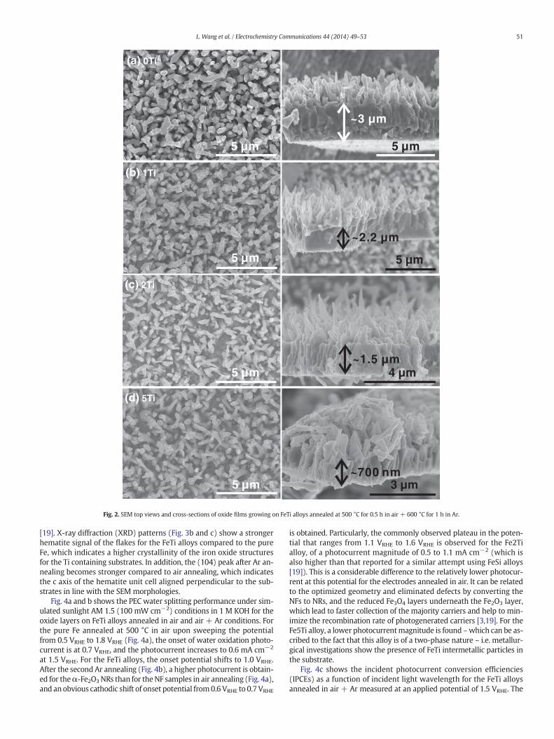
(600 °C) to modify the morphology. Figs. 1 and 2 show the morphol-ogies of FeTi substrates after the growth of oxide flakes by air annealingand after conversion to nanorods (NRs) in Ar. At 500 °C in air, pureFe NFs are in dense arrays with sharp apexes (Fig. 1a). The flakes areof 1.5–2.5 μm in length, 200–500 nm thick at the base that tapersdown to approximately 10 nm at the tips. At 600 °C in Ar, robust NRsare formed that typically have a length of ~2.5 μm and a diameter of100–200 nm (Fig. 2a). In comparison with pure iron, the Ti alloysshow a slightly lower density of NFs with increasing Ti concentration.A most significant difference between alloys and pure iron substrate isapparent from the cross sections. The thickness of the oxide layer onthe Fe substrate is with ~2.5 μm clearly higher than on the Ti containingalloys (500 nm–2 μm). The GDOES elemental profile (Fig. 3a) showsthat the FeTi alloy is enriched in titanium at the metal/oxide interface.This is attributed to the addition of Ti and a protective TiO2 layer as ob-served to improve the steam oxidation resistance on iron-based alloys[20], and as in previous work for the SiO2 formation on FeSi alloys
~2.5 µm
4 µm
~2 µm
~1.2 µm
~500 nm
3 µm
2 µm
1 µm
growing on FeTi alloys annealed at 500 °C for 0.5 h in air.
5 µm
(a) 0Ti
5 µm
~3 µm
(b) 1Ti
(c) 2Ti
(d) 5Ti
5 µm
5 µm
5 µm
5 µm
4 µm
3 µm
~2.2 µm
~1.5 µm
~700 nm
Fig. 2. SEM top views and cross-sections of oxide films growing on FeTi alloys annealed at 500 °C for 0.5 h in air + 600 °C for 1 h in Ar.
51L. Wang et al. / Electrochemistry Communications 44 (2014) 49–53
[19]. X-ray diffraction (XRD) patterns (Fig. 3b and c) show a strongerhematite signal of the flakes for the FeTi alloys compared to the pureFe, which indicates a higher crystallinity of the iron oxide structuresfor the Ti containing substrates. In addition, the (104) peak after Ar an-nealing becomes stronger compared to air annealing, which indicatesthe c axis of the hematite unit cell aligned perpendicular to the sub-strates in line with the SEM morphologies.
Fig. 4a and b shows the PEC water splitting performance under sim-ulated sunlight AM 1.5 (100 mW cm−2) conditions in 1 M KOH for theoxide layers on FeTi alloys annealed in air and air + Ar conditions. Forthe pure Fe annealed at 500 °C in air upon sweeping the potentialfrom 0.5 VRHE to 1.8 VRHE (Fig. 4a), the onset of water oxidation photo-current is at 0.7 VRHE, and the photocurrent increases to 0.6 mA cm−2
at 1.5 VRHE. For the FeTi alloys, the onset potential shifts to 1.0 VRHE.After the second Ar annealing (Fig. 4b), a higher photocurrent is obtain-ed for theα-Fe2O3NRs than for theNF samples in air annealing (Fig. 4a),and anobvious cathodic shift of onset potential from0.6 VRHE to 0.7 VRHE
is obtained. Particularly, the commonly observed plateau in the poten-tial that ranges from 1.1 VRHE to 1.6 VRHE is observed for the Fe2Tialloy, of a photocurrent magnitude of 0.5 to 1.1 mA cm−2 (which isalso higher than that reported for a similar attempt using FeSi alloys[19]). This is a considerable difference to the relatively lower photocur-rent at this potential for the electrodes annealed in air. It can be relatedto the optimized geometry and eliminated defects by converting theNFs to NRs, and the reduced Fe3O4 layers underneath the Fe2O3 layer,which lead to faster collection of the majority carriers and help to min-imize the recombination rate of photogenerated carriers [3,19]. For theFe5Ti alloy, a lower photocurrentmagnitude is found –which can be as-cribed to the fact that this alloy is of a two-phase nature – i.e. metallur-gical investigations show the presence of FeTi intermetallic particles inthe substrate.
Fig. 4c shows the incident photocurrent conversion efficiencies(IPCEs) as a function of incident light wavelength for the FeTi alloysannealed in air + Ar measured at an applied potential of 1.5 VRHE. The

0 20 40 60 800
1
2
3
(a) In
tens
ity (
U)
Sputter time (sec.)
Fe
Ti
O
40 50 60 70
Inte
nsity
(a.
u.)
2Ti
1Ti
(b) air
0Ti
5Ti
-Fe2O
3
Fe3O
4
Fe
40 50 60 70
(c) air/Ar
Inte
nsity
(a.
u.)
2θ (degree)
2θ (degree)
-Fe2O
3
Fe3O
4
5Ti
2Ti
1Ti
0Ti
Fe
Fig. 3. (a) GDOES elemental depth profile of the oxide layer on the Fe2Ti alloy; (b,c) XRDpatterns of oxide films grown on FeTi alloys annealed at (b) 500 °C for 0.5 h in air and(c) 500 °C for 0.5 h in air + 600 °C for 1 h in Ar.
52 L. Wang et al. / Electrochemistry Communications 44 (2014) 49–53
IPCE data are in line with the measurements using AM 1.5 conditions(Fig. 4b). Over the entire range from 300 nm to 550 nm, Fe2Ti alloyleads to a maximum IPCE value (10.2%) at 340 nm compared to othersamples. From a replot according to an indirect electron transition(iphhυ)1/2 vs. photon energy (hυ), in all cases a band gap Eg of approx.1.9–2.1 eV (Fig. 4d), i.e. corresponding to hematite [3], can be evaluated.These results imply that the increased IPCE value is likely due to thebeneficial effect of Ar annealing. This explanation becomes more clearfrom the transient photoresponse behavior as shown in Fig. 4e and f.The transients have a very similar shape (initial decay) after Ar anneal-ing. The transient behavior depends strongly on the density and energyof the trapping states [21]. The reduction of the transients in Ar
condition implies a smaller density of trapping states as compared toair annealing. On the other hand, the enhanced PEC performancecould be attributed to the increased donor density of the hematite NRsas a result of the formation of oxygen vacancies (Fe2+), which serveas a shallow donor and therefore increase the electrical conductivity ofhematite [22]. The increased electron density could improve chargeseparation at the semiconductor/electrolyte interface, reduce the ener-gy loss in the semiconductor, and decrease the contact resistance atthe semiconductor/oxide layer interface.
4. Conclusions
In summary, in this work we form oxide nanoflakes by thermal oxi-dation of FeTi alloys in air and nanorod structure after additional Arannealing. An enhanced water splitting performance of hematite nano-rods is obtained for the FeTi alloys as compared to pure Fe (and com-pared to previous work on FeSi alloys). A remarkable cathodic shift ofonset potential up to 0.6 VRHE and increased water splitting near theonset potential are observed for the FeTi alloys. This is attributed tothe beneficial effect of titanium oxide layer at the metal/oxide interfacewhich hampers the formation of suboxide layers (Fe3O4), as well as tothe increased crystallinity of the hematite formed on the FeTi alloys.This work represents a valuable platform for further modification ofiron substrates with nanowires or nanoflakes towards an optimizedwater splitting performance, and opens a new avenue for improvingthe efficiency of hematite based structures for approaches of the solar-to-fuel conversion.
Conflict of interest
None.
Acknowledgments
The authors would like to acknowledge Dr. Natalie Kömpel (NeueMaterialien Fürch GmbH, NMF) for GDOES measurements. We thankDFG and the DFG cluster of excellence “Engineering of Advanced Mate-rials” (EAM) for the financial support.
References
[1] A. Fujishima, K. Honda, Nature 238 (1972) 37.[2] J. Brillet, M. Grätzel, K. Sivula, Nano Lett. 10 (2010) 4155.[3] K. Sivula, F.L. Formal, M. Grätzel, Chem. Sus. Chem. 4 (2011) 432.[4] K. Sivula, R. Zboril, F.L. Formal, R. Robert, A. Weiden kaff, J. Tucek, J. Frydrych, M.
Grätzel, J. Am. Chem. Soc. 132 (2010) 7436.[5] S.D. Tilley, M. Cornuz, K. Sivula, M. Grätzel, Angew. Chem. Int. Ed. 49 (2010) 6405.[6] Y. Lin, G. Yuan, S. Sheehan, S. Zhou, D. Wang, Energy Environ. Sci. 5 (2011) 4862.[7] D.A.Wheeler, G.M.Wang, Y.C. Ling, Y. Li, J.Z. Zhang, Energy Environ. Sci. 5 (2012) 6682.[8] A.J. Cowan, J.R. Durrant, Chem. Soc. Rev. 42 (2013) 2281.[9] K.M.H. Young, B.M. Klahr, O. Zandi, T.W. Hamann, Catal. Sci. Technol. 3 (2013) 1660.
[10] Z.S. Li, W.J. Luo, M.L. Zhang, J.Y. Feng, Z.G. Zhou, Energy Environ. Sci. 6 (2013) 347.[11] L. Wang, C.-Y. Lee, P. Schmuki, Electrochem. Commun. 30 (2013) 21.[12] L. Wang, C.-Y. Lee, A. Mazare, K. Lee, J. Müller, E. Spiecker, P. Schmuki, Chem. Eur. J.
20 (2014) 77.[13] L. Wang, A. Palacios-Padrós, R. Kirchgeorg, A. Tighineanu, P. Schmuki, Chem. Sus.
Chem. 7 (2014) 421.[14] X. Wen, S. Wang, Y. Ding, Z.L. Wang, S. Yang, J. Phys. Chem. B 109 (2005) 215.[15] C.-Y. Lee, L. Wang, Y. Kado, M.S. Killian, P. Schmuki, Chem. Sus. Chem. 7 (2014)
934.[16] A.B. Murphy, P.R.F. Barnes, L.K. Randeniya, I.C. Plumb, I.E. Grey, M.D. Horne, J.A.
Glasscock, Int. J. Hydrogen Energy 31 (2006) 1999.[17] T. Vincent, M. Gross, H. Dotan, A. Rothschild, Int. J. Hydrogen Energy 37 (2012)
8102.[18] B.D. Chernomordik, H.B. Russell, U. Cvelbar, J.B. Jasinski, V. Kumar, T. Deutsch, M.K.
Sunkara, Nanotechnology 23 (2012) 194009.[19] L. Wang, C.-Y. Lee, R. Kirchgeorg, H. Hildebrand, J. Muller, E. Spiecker, P. Schmuki,
Mater. Horiz. 3 (2014) 344.[20] A. Fry, S. Osgerby,M.Wright, NPL ReportMATC (A) 90, National Physical Laboratory,
UK, July 2002.[21] P. Iwanski, J. Curran, W. Gissler, R. Memming, J. Electrochem. Soc. 128 (1981) 2128.[22] Y. Ling, G.Wang, J. Reddy, C.Wang, J.Z. Zhang, Y. Li, Angew. Chem. Int. Ed. 51 (2012)
4074

0.6 0.8 1.0 1.2 1.4 1.6 1.8 2.0
0.0
0.3
0.6
0.9
1.2
1.5
1.8
1Ti
5Ti
2Ti
0Ti
Potential (V vs. RHE)
(b) air/Ar
0.6 0.8 1.0 1.2 1.4 1.6 1.8 2.0
0.0
0.3
0.6
0.9
1.2
1.5
1.8
5Ti
1Ti
Potential (V vs. RHE)
(a) air
2Ti
0Ti
0 20 40 60 80 100-5
0
5
10
15
20
25
30
air
air/Ar
Time (sec.)
(f)
0 20 40 60 80 100
0
5
10
15
20
25
30
0Ti
(e)2Ti
1Ti
5Ti
Time (sec.)
1.8 2.1 2.4 2.7 3.0 3.3
0Ti1Ti2Ti5Ti
Photon energy (eV)
(d)
300 350 400 450 500 550 6000
2
4
6
8
10
12 0Ti1Ti2Ti5Ti
IPC
E (
%)
Wavelength (nm)
(c)
Cur
rent
den
sity
(μA
cm
-2)
Cur
rent
den
sity
(μA
cm
-2)
(Iph
hν)1/
2
Cur
rent
den
sity
(m
A c
m-2
)
Cur
rent
den
sity
(m
A c
m-2
)
Fig. 4. (a,b) Current-potential characteristics with chopped light ofα-Fe2O3 layers on FeTi alloys annealed (a) in air and (b) air +Ar conditions, respectively. Conditions: 1 M KOH solution(pH 13.6), 2mV s−1 scan rate. Photocurrents are excited to AM1.5, 100mWcm−2 simulated sunlight. (c) Incident photon conversion efficiencies (IPCEs) at an appliedpotential of 1.5 VRHE
in 1M KOH solution for FeTi alloys annealed in air + Ar condition; (d) band gap determination from the (iphhυ)1/2 vs. photon energy (hυ) plots for the corresponding FeTi alloys; (e) pho-tocurrent at 360 nmat 1.5 VRHE in 1MKOH for the corresponding FeTi alloys; and (f) photocurrent at 360 nmat 1.5 VRHE in 1MKOH for Fe2Ti alloy annealed in air and air+Ar conditions.
53L. Wang et al. / Electrochemistry Communications 44 (2014) 49–53