in the year 2000, ingersoll cutting tool company came to ... · in the year 2000, ingersoll cutting...
TRANSCRIPT


In the year 2000, Ingersoll Cutting Tool Company came to realize that in order to better serve our customers inthe demanding world of metal removal, it was time to expand our horizons and become a full line supplier to themetal working industry. To that end Ingersoll introduced a line of inovative, technologically superior drills androlled out it’s first ever comprehensive “Hole Making” catalog.
Now five years later, due in a large part to the popularity of both the Qwik-Twist and Quad-Drill+ lines of drillingproducts, the “BOREline” is the fastest growing division at Ingersoll Cutting Tools.
In this new “BOREline” catalog we’ve expanded both the Qwik-Twist and Quad-Drill+ lines and added excitingnew products such as Ingersoll Gun Drills and a complete line of Rotary Tool Holders.
Our network of distribution partners supported by our sales engineering staff is an invaluable resource of tech-nical tooling application expertise and customer support. These highly trained, skilled individuals are availableto you on-site in your facility until our products are performing the way you expect.
We are more than just a tooling supplier. We want you to view us as partners . . . as a specialized extension ofyour own process engineering capabilities. We have the resources and experience you need to make informedand effective tooling decisions.
Our goal is to help you remain competitive in a rapidly changing manufacturing environment, with the latest andmost productive hole making tools in the industry.
P.S. For all of your finish precision boring needs, please refer to Ingersoll’s “D’Andrea” Modular Boring catalog.
Sincerely,The Ingersoll “BOREline” Team


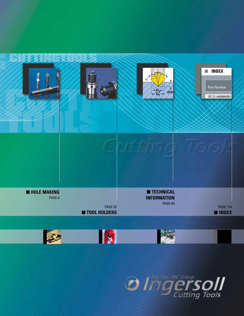
� HOLE MAKINGPAGE 6
� TECHNICALINFORMATION
PAGE 84PAGE 52
� TOOL HOLDERSPAGE 114
� INDEX


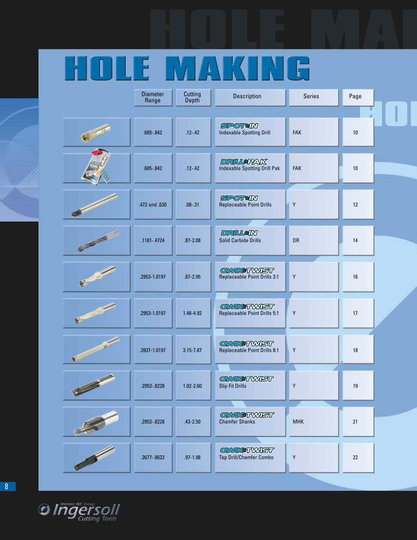
8
Diameter CuttingRange Depth
Description Series Page
.685-.842 .12-.42 Indexable Spotting Drill FAK 10
.685-.842 .12-.42 Indexable Spotting Drill Pak FAK 10
.472 and .630 .08-.31 Replaceable Point Drills Y 12
.1181-.4724 .87-2.08 Solid Carbide Drills DR 14
.2953-1.0197 .87-2.95 Replaceable Point Drills 3:1 Y 16
.2953-1.0197 1.46-4.92 Replaceable Point Drills 5:1 Y 17
.3937-1.0197 3.15-7.87 Replaceable Point Drills 8:1 Y 18
.2953-.8228 1.02-2.60 Slip Fit Drills Y 19
.2953-.8228 .43-2.50 Chamfer Shanks MHK 21
.2677-.8622 .97-1.98 Tap Drill/Chamfer Combo Y 22
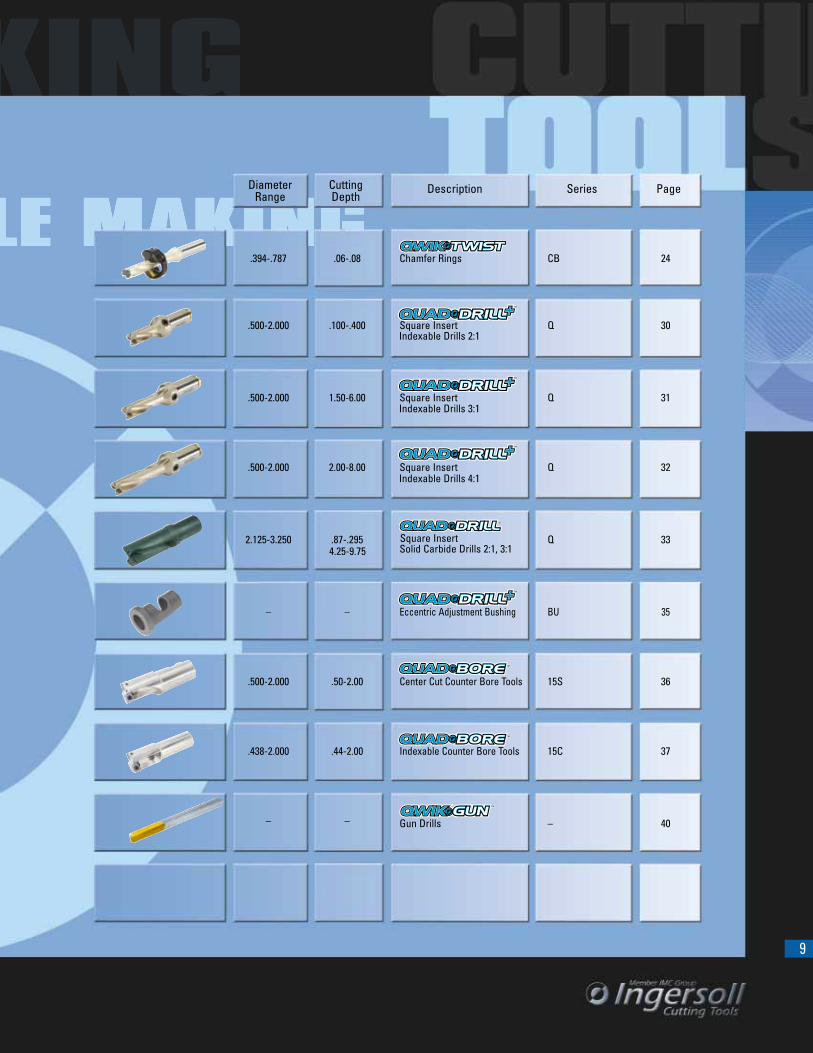
9
Diameter CuttingRange Depth
Description Series Page
.394-.787 .06-.08 Chamfer Rings CB 24
.500-2.000 .100-.400 Square Insert Q 30
.500-2.000 1.50-6.00 Square Insert Q 31
.500-2.000 2.00-8.00 Square Insert Q 32
2.125-3.250 .87-.295Solid Carbide Drills 2:1, 3:1
Q 33
– – Eccentric Adjustment Bushing BU 35
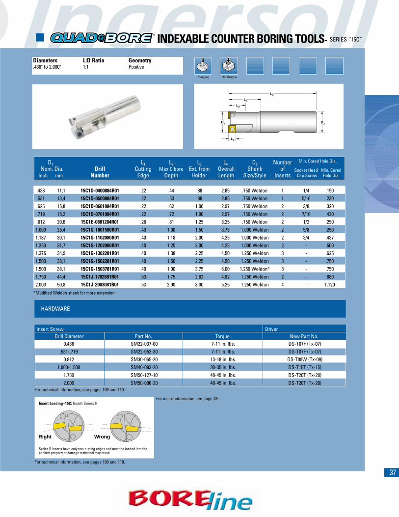
.500-2.000 .50-2.00 Center Cut Counter Bore Tools 15S 36
.438-2.000 .44-2.00 Indexable Counter Bore Tools 15C 37
– – Gun Drills – 40
Indexable Drills 3:1
Indexable Drills 2:1
Indexable Drills 4:1
Square Insert4.25-9.75
10
Spot Drilling
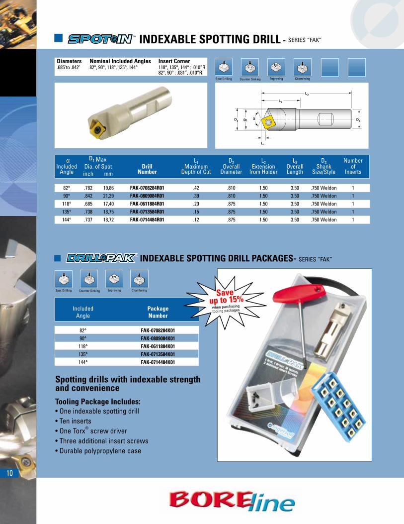
� INDEXABLE SPOTTING DRILL - SERIES “FAK”
Counter Sinking
αD1D2
L1
L2
L3
D3
Engraving Chamfering
α D1 Max L1 D2 L2 L3 D3 NumberIncluded Dia. of Spot Drill Maximum Overall Extension Overall Shank of
Angle inch mm Number Depth of Cut Diameter from Holder Length Size/Style Inserts
82° .782 19,86 FAK-0708284R01 .42 .810 1.50 3.50 .750 Weldon 190° .842 21,39 FAK-0809084R01 .39 .810 1.50 3.50 .750 Weldon 1118° .685 17,40 FAK-0611884R01 .20 .875 1.50 3.50 .750 Weldon 1135° .738 18,75 FAK-0713584R01 .15 .875 1.50 3.50 .750 Weldon 1144° .737 18,72 FAK-0714484R01 .12 .875 1.50 3.50 .750 Weldon 1
Diameters Nominal Included Angles Insert Corner.685"to .842" 82°, 90°, 118°, 135°, 144° 118°, 135°, 144° : .010”R
82°, 90° : .031”, .010”R
� INDEXABLE SPOTTING DRILL PACKAGES- SERIES “FAK”
Spot Drilling Counter Sinking Engraving Chamfering
Included PackageAngle Number
82° FAK-0708284K0190° FAK-0809084K01
118° FAK-0611884K01135° FAK-0713584K01144° FAK-0714484K01
Spotting drills with indexable strength and convenienceTooling Package Includes:• One indexable spotting drill• Ten inserts• One Torx® screw driver• Three additional insert screws• Durable polypropylene case
Saveup to 15%
when purchasingtooling packages
11
.181 .414
INSERTS
HARDWARE
.156
.031R.537
For technical information, see pages 91 and 92.
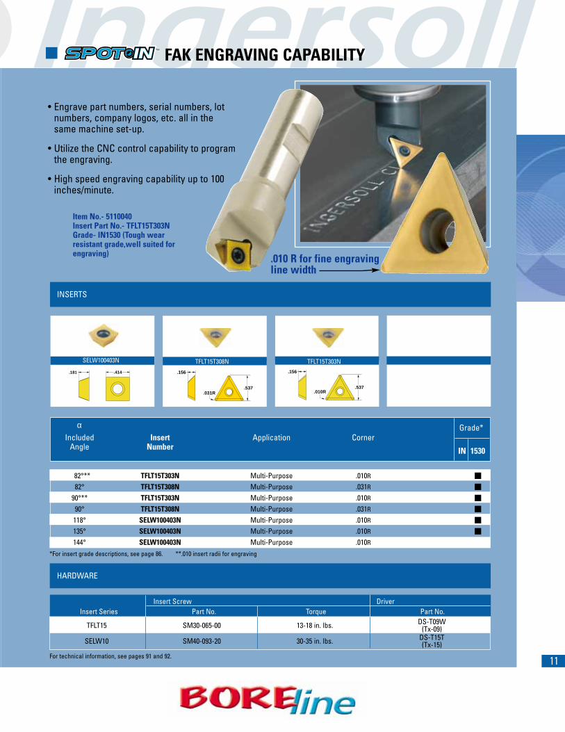
� FAK ENGRAVING CAPABILITY
SELW100403N TFLT15T308N
Grade*
.156
.010R.537
αIncluded Insert Application Corner
Angle Number IN 1530
82°** TFLT15T303N Multi-Purpose .010R
82° TFLT15T308N Multi-Purpose .031R
90°** TFLT15T303N Multi-Purpose .010R
90° TFLT15T308N Multi-Purpose .031R
118° SELW100403N Multi-Purpose .010R
135° SELW100403N Multi-Purpose .010R
144° SELW100403N Multi-Purpose .010R
�
�
�
�
�
�
*For insert grade descriptions, see page 86. **.010 insert radii for engraving
Insert Screw DriverInsert Series Part No. Torque Part No.
TFLT15 SM30-065-00 13-18 in. lbs. DS-T09W(Tx-09)
SELW10 SM40-093-20 30-35 in. lbs. DS-T15T(Tx-15)
TFLT15T303N
• Engrave part numbers, serial numbers, lot numbers, company logos, etc. all in the same machine set-up.
• Utilize the CNC control capability to program the engraving.
• High speed engraving capability up to 100 inches/minute.
Item No.- 5110040Insert Part No.- TFLT15T303NGrade- IN1530 (Tough wear resistant grade,well suited for engraving) .010 R for fine engraving
line width
12
Spot Drilling
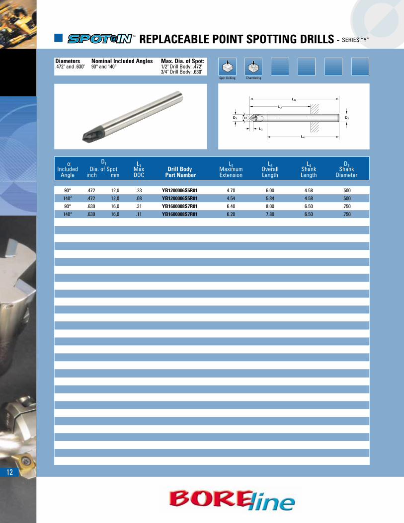
� REPLACEABLE POINT SPOTTING DRILLS - SERIES “Y”
Diameters Nominal Included Angles Max. Dia. of Spot:.472" and .630" 90° and 140° 1/2" Drill Body: .472"
3/4" Drill Body: .630"Chamfering
D1 D2
L2
L3
L1
L4
α D1 L1 L2 L3 L4 D2Included Dia. of Spot Max Drill Body Maximum Overall Shank Shank
Angle inch mm DOC Part Number Extension Length Length Diameter
90° .472 12,0 .23 YB1200006S5R01 4.70 6.00 4.58 .500140° .472 12,0 .08 YB1200006S5R01 4.54 5.84 4.58 .50090° .630 16,0 .31 YB1600008S7R01 6.40 8.00 6.50 .750140° .630 16,0 .11 YB1600008S7R01 6.20 7.80 6.50 .750
139
INSERTS
HARDWARE
YCB1200R01 YAB1200R01 YCB1600R01 YAB1600R01
INSERTS
For technical information, see pages 91,92 and 93.
.472
90
.472
14090
.630 .630
140
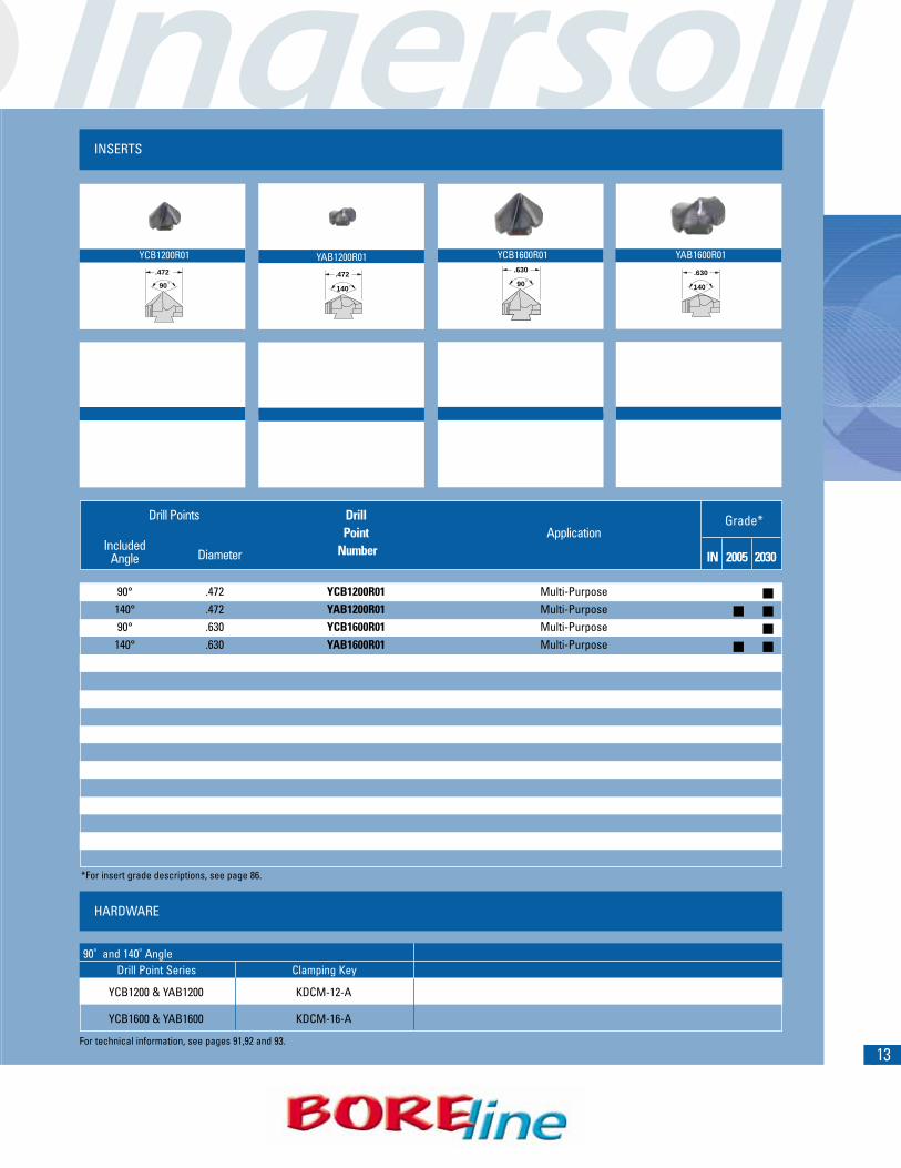
Drill Points DrillPoint Application
IncludedDiameter Number IN 2005 2030Angle
90° .472 YCB1200R01 Multi-Purpose140° .472 YAB1200R01 Multi-Purpose90° .630 YCB1600R01 Multi-Purpose140° .630 YAB1600R01 Multi-Purpose
�
� �
�
� �
*For insert grade descriptions, see page 86.
90˚ and 140˚ AngleDrill Point Series Clamping Key
YCB1200 & YAB1200 KDCM-12-A
YCB1600 & YAB1600 KDCM-16-A
Grade*
14
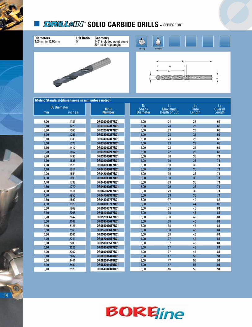
Drilling Coolant
Metric Standard-(dimensions in mm unless noted)D2 L1 L2 L3D1 Diameter Drill Shank Maximum Flute Overall
mm inches Number Diameter Depth of Cut Length Length
3,00 .1181 DR0300024T7R01 6,00 24 28 663,10 .1220 DR0310023T7R01 6,00 23 28 663,20 .1260 DR0320023T7R01 6,00 23 28 663,30 .1299 DR0330023T7R01 6,00 23 28 663,40 .1339 DR0340023T7R01 6,00 23 28 663,50 .1378 DR0350023T7R01 6,00 23 28 663,60 .1417 DR0360023T7R01 6,00 23 28 663,70 .1457 DR0370022T7R01 6,00 22 28 663,80 .1496 DR0380030T7R01 6,00 30 36 743,90 .1535 DR0390030T7R01 6,00 30 36 744,00 .1575 DR0400030T7R01 6,00 30 36 744,10 .1614 DR0410030T7R01 6,00 30 36 744,20 .1654 DR0420030T7R01 6,00 30 36 744,30 .1693 DR0430030T7R01 6,00 30 36 744,40 .1732 DR0440029T7R01 6,00 29 36 744,50 .1772 DR0450029T7R01 6,00 29 36 744,60 .1811 DR0460029T7R01 6,00 29 36 744,70 .1850 DR0470029T7R01 6,00 29 36 744,80 .1890 DR0480037T7R01 6,00 37 44 824,90 .1929 DR0490037T7R01 6,00 37 44 825,00 .1969 DR0500037T7R01 6,00 39 46 845,10 .2008 DR0510036T7R01 6,00 38 46 845,20 .2047 DR0520036T7R01 6,00 38 46 845,30 .2087 DR0530036T7R01 6,00 38 46 845,40 .2126 DR0540036T7R01 6,00 38 46 845,50 .2165 DR0550036T7R01 6,00 38 46 845,60 .2205 DR0560036T7R01 6,00 38 46 845,70 .2244 DR0570035T7R01 6,00 37 46 845,80 .2283 DR0580035T7R01 6,00 37 46 845,90 .2323 DR0590035T7R01 6,00 37 46 846,00 .2362 DR0600035T7R01 6,00 37 46 846,10 .2402 DR0610044T0R01 8,00 47 56 946,20 .2441 DR0620044T0R01 8,00 47 56 946,30 .2480 DR0630044T0R01 8,00 47 56 946,40 .2520 DR0640043T0R01 8,00 46 56 94
� SOLID CARBIDE DRILLS - SERIES “DR”
Diameters L:D Ratio Geometry3,00mm to 12,00mm 5:1 140° included point angle
30° axial rake angle
L3
L1
L2
D1 D2
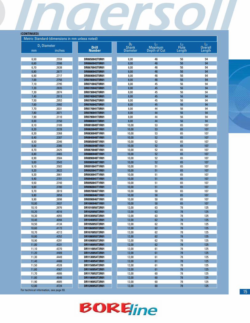
15
(CONTINUED)
Metric Standard-(dimensions in mm unless noted)D2 L1 L2 L3D1 Diameter Drill Shank Maximum Flute Overall
mm inches Number Diameter Depth of Cut Length Length
6,50 .2559 DR0650043T0R01 8,00 46 56 946,60 .2598 DR0660043T0R01 8,00 46 56 946,70 .2638 DR0670043T0R01 8,00 46 56 946,80 .2677 DR0680043T0R01 8,00 46 56 946,90 .2717 DR0690043T0R01 8,00 46 56 947,00 .2756 DR0700043T0R01 8,00 46 56 947,10 .2795 DR0710042T0R01 8,00 45 56 947,20 .2835 DR0720042T0R01 8,00 45 56 947,30 .2874 DR0730042T0R01 8,00 45 56 947,40 .2913 DR0740042T0R01 8,00 45 56 947,50 .2953 DR0750042T0R01 8,00 45 56 947,60 .2992 DR0760042T0R01 8,00 45 56 947,70 .3031 DR0770041T0R01 8,00 44 56 947,80 .3071 DR0780041T0R01 8,00 44 56 947,90 .3110 DR0790041T0R01 8,00 44 56 948,00 .3150 DR0800041T0R01 8,00 44 56 948,10 .3189 DR0810049T1R01 10,00 53 65 1078,20 .3228 DR0820049T1R01 10,00 53 65 1078,30 .3268 DR0830049T1R01 10,00 53 65 1078,40 .3307 DR0840048T1R01 10,00 52 65 1078,50 .3346 DR0850048T1R01 10,00 52 65 1078,60 .3386 DR0860048T1R01 10,00 52 65 1078,70 .3425 DR0870048T1R01 10,00 52 65 1078,80 .3465 DR0880048T1R01 10,00 52 65 1078,90 .3504 DR0890048T1R01 10,00 52 65 1079,00 .3543 DR0900048T1R01 10,00 52 65 1079,10 .3583 DR0910047T1R01 10,00 51 65 1079,20 .3622 DR0920047T1R01 10,00 51 65 1079,30 .3661 DR0930047T1R01 10,00 51 65 1079,40 .3701 DR0940047T1R01 10,00 51 65 1079,50 .3740 DR0950047T1R01 10,00 51 65 1079,60 .3780 DR0960047T1R01 10,00 51 65 1079,70 .3819 DR0970046T1R01 10,00 50 65 1079,80 .3858 DR0980046T1R01 10,00 50 65 1079,90 .3898 DR0990046T1R01 10,00 50 65 10710,00 .3937 DR1000046T1R01 10,00 50 65 10710,10 .3976 DR1010056T2R01 12,00 63 78 12510,20 .4016 DR1020056T2R01 12,00 63 78 12510,30 .4055 DR1030056T2R01 12,00 63 78 12510,40 .4094 DR1040055T2R01 12,00 62 78 12510,50 .4134 DR1050055T2R01 12,00 62 78 12510,60 .4173 DR1060055T2R01 12,00 62 78 12510,70 .4213 DR1070055T2R01 12,00 62 78 12510,80 .4252 DR1080055T2R01 12,00 62 78 12510,90 .4291 DR1090055T2R01 12,00 62 78 12511,00 .4331 DR1100055T2R01 12,00 62 78 12511,10 .4370 DR1110054T2R01 12,00 61 78 12511,20 .4409 DR1120054T2R01 12,00 61 78 12511,30 .4449 DR1130054T2R01 12,00 61 78 12511,40 .4488 DR1140054T3R01 12,00 61 78 12511,50 .4528 DR1150054T2R01 12,00 61 78 12511,60 .4567 DR1160054T2R01 12,00 61 78 12511,70 .4606 DR1170053T2R01 12,00 60 78 12511,80 .4646 DR1180053T2R01 12,00 60 78 12511,90 .4685 DR1190053T2R01 12,00 60 78 12512,00 .4724 DR1200053T2R01 12,00 60 78 125
For technical information, see page 93.
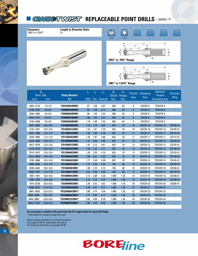
16
D1 L1 L2 L3 D2 D3 Pocket Clamping Optional ChamferNom. Dia. Body Number Shank Flange Size KeyTorque
Ringinch mm 3:1 DOC Ext. Overall Dia. Dia. Clamping Key
.2953-.3110 7,5-7,9 YD0750022B9R01 .87 1.30 3.07 .500 .63 8 KDCM-8 TKDCM-8 -
.3150-.3307 8,0-8,4 YD0800024B9R01 .94 1.38 3.15 .500 .63 8 KDCM-8 TKDCM-8 -
.3346-.3504 8,5-8,9 YD0850025B9R01 .98 1.46 3.23 .500 .63 8 KDCM-8 TKDCM-8 -
.3543-.3701 9,0-9,4 YD0900027B9R01 1.06 1.54 3.31 .500 .63 9 KDCM-9 TKDCM-9 -
.3740-.3898 9,5-9,9 YD0950028B9R01 1.10 1.68 3.45 .500 .63 9 KDCM-9 TKDCM-9 -
.3937-.4094 10,0-10,4 YD1000030C0R01 1.18 1.73 3.62 .625 .79 10 KDCM-10 TKDCM-10 CB100-01
.4134-.4291 10,5-10,9 YD1050031C0R01 1.24 1.81 3.70 .625 .79 10 KDCM-10 TKDCM-10 CB105-01
.4331-.4488 11,0-11,4 YD1100033C0R01 1.30 1.89 3.78 .625 .79 11 KDCM-11 TKDCM-11 CB110-01
.4528-.4685 11,5-11,9 YD1150034C0R01 1.35 1.97 3.86 .625 .79 11 KDCM-11 TKDCM-11 CB115-01
.4724-.4882 12,0-12,4 YD1200036C0R01 1.41 2.06 3.95 .625 .79 12 KDCM-12 TKDCM-12 CB120-01
.4912-.5079 12,5-12,9 YD1250037C0R01 1.47 2.12 4.01 .625 .79 12 KDCM-12 TKDCM-12 CB125-01
.5118-.5276 13,0-13,4 YD1300039C0R01 1.53 2.22 4.11 .625 .79 13 KDCM-13 TKDCM-13 CB130-01
.5315-.5472 13,5-13,9 YD1350040C0R01 1.59 2.30 4.19 .625 .79 13 KDCM-13 TKDCM-13 CB135-01
.5512-.5669 14,0-14,4 YD1400042C0R01 1.65 2.41 4.30 .625 .79 14 KDCM-14 TKDCM-14 CB140-01
.5709-.5866 14,5-14,9 YD1450043C0R01 1.71 2.49 4.38 .625 .79 14 KDCM-14 TKDCM-14 CB145-01
.5906-.6260 15,0-15,9 YD150004518R01 1.77 2.58 4.55 .750 .98 15 KDCM-15 TKDCM-15 CB150-01
.6299-.6654 16,0-16,9 YD160004818R01 1.89 2.75 4.72 .750 .98 16 KDCM-16 TKDCM-16 CB160-01
.6693-.7047 17,0-17,9 YD170005118R01 2.01 2.89 4.86 .750 .98 17 KDCM-17 TKDCM-17 CB170-01
.7087-.7441 18,0-18,9 YD1800054C8R01 2.13 3.08 5.28 1.000 1.26 18 KDCM-18 TKDCM-18 CB180-01
.7480-.7835 19,0-19,9 YD1900057C8R01 2.24 3.24 5.44 1.000 1.26 19 KDCM-19 TKDCM-19 CB190-01
.7874-.8228 20,0-20,9 YD2000060C8R01 2.36 3.42 5.62 1.000 1.26 20 KDCM-20 TKDCM-20 CB200-01
.8268-.8622 21,0-21,9 YD2100063C8R01 2.48 3.57 5.77 1.000 1.26 21 KDCM-21 TKDCM-21 -
.8661-.9016 22,0-22,9 YD2200066C8R01* 2.60 3.74 5.94 1.000 1.26 22 KDCM-22 TKDCM-22 -.9055-.9409 23,0-23,9 YD2300069C8R01* 2.71 3.92 6.12 1.000 1.26 23 KDCM-23 TKDCM-23 -.9449-.9803 24,0-24,9 YD2400072C8R01* 2.83 4.08 6.28 1.000 1.26 24 KDCM-24 TKDCM-24 -.9843-1.0197 25,0-25,9 YD2500075C8R01* 2.95 4.29 6.49 1.000 1.26 25 KDCM-25 TKDCM-25 -
Drilling Coolant
� REPLACEABLE POINT DRILLS - SERIES “Y”
Diameters Length to Diameter Ratio.2953" to 1.0197" 3:1
Do not mount a smaller drill point than the D1 range listed for each drill body.* Drill bodies for coolant through the point.
Metric shanks available as non-stock standards.See pages 25-29 for replaceable drill points.For technical information, see pages 95-99.
D1
D3
L1
L2
L3
D2
D1
D3
L1
L2
L3
D2
.2953” to .7047” Range
.7087” to 1.0197” Range
17
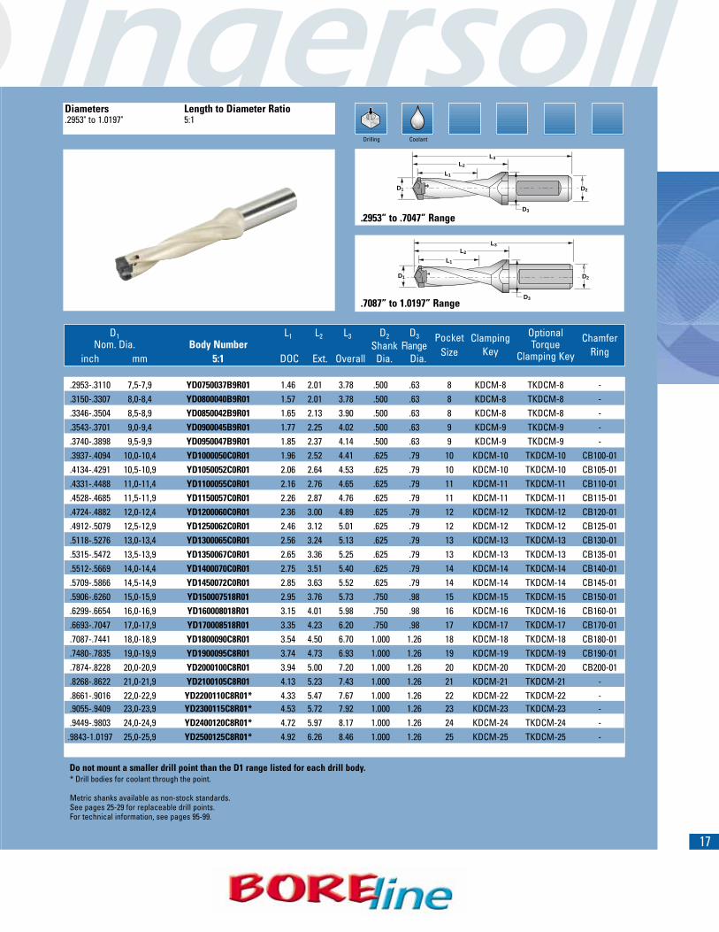
D1 L1 L2 L3 D2 D3 Pocket Clamping Optional ChamferNom. Dia. Body Number Shank Flange Size KeyTorque
Ringinch mm 5:1 DOC Ext. Overall Dia. Dia. Clamping Key
.2953-.3110 7,5-7,9 YD0750037B9R01 1.46 2.01 3.78 .500 .63 8 KDCM-8 TKDCM-8 -
.3150-.3307 8,0-8,4 YD0800040B9R01 1.57 2.01 3.78 .500 .63 8 KDCM-8 TKDCM-8 -
.3346-.3504 8,5-8,9 YD0850042B9R01 1.65 2.13 3.90 .500 .63 8 KDCM-8 TKDCM-8 -
.3543-.3701 9,0-9,4 YD0900045B9R01 1.77 2.25 4.02 .500 .63 9 KDCM-9 TKDCM-9 -
.3740-.3898 9,5-9,9 YD0950047B9R01 1.85 2.37 4.14 .500 .63 9 KDCM-9 TKDCM-9 -
.3937-.4094 10,0-10,4 YD1000050C0R01 1.96 2.52 4.41 .625 .79 10 KDCM-10 TKDCM-10 CB100-01
.4134-.4291 10,5-10,9 YD1050052C0R01 2.06 2.64 4.53 .625 .79 10 KDCM-10 TKDCM-10 CB105-01
.4331-.4488 11,0-11,4 YD1100055C0R01 2.16 2.76 4.65 .625 .79 11 KDCM-11 TKDCM-11 CB110-01
.4528-.4685 11,5-11,9 YD1150057C0R01 2.26 2.87 4.76 .625 .79 11 KDCM-11 TKDCM-11 CB115-01
.4724-.4882 12,0-12,4 YD1200060C0R01 2.36 3.00 4.89 .625 .79 12 KDCM-12 TKDCM-12 CB120-01
.4912-.5079 12,5-12,9 YD1250062C0R01 2.46 3.12 5.01 .625 .79 12 KDCM-12 TKDCM-12 CB125-01
.5118-.5276 13,0-13,4 YD1300065C0R01 2.56 3.24 5.13 .625 .79 13 KDCM-13 TKDCM-13 CB130-01
.5315-.5472 13,5-13,9 YD1350067C0R01 2.65 3.36 5.25 .625 .79 13 KDCM-13 TKDCM-13 CB135-01
.5512-.5669 14,0-14,4 YD1400070C0R01 2.75 3.51 5.40 .625 .79 14 KDCM-14 TKDCM-14 CB140-01
.5709-.5866 14,5-14,9 YD1450072C0R01 2.85 3.63 5.52 .625 .79 14 KDCM-14 TKDCM-14 CB145-01
.5906-.6260 15,0-15,9 YD150007518R01 2.95 3.76 5.73 .750 .98 15 KDCM-15 TKDCM-15 CB150-01
.6299-.6654 16,0-16,9 YD160008018R01 3.15 4.01 5.98 .750 .98 16 KDCM-16 TKDCM-16 CB160-01
.6693-.7047 17,0-17,9 YD170008518R01 3.35 4.23 6.20 .750 .98 17 KDCM-17 TKDCM-17 CB170-01
.7087-.7441 18,0-18,9 YD1800090C8R01 3.54 4.50 6.70 1.000 1.26 18 KDCM-18 TKDCM-18 CB180-01
.7480-.7835 19,0-19,9 YD1900095C8R01 3.74 4.73 6.93 1.000 1.26 19 KDCM-19 TKDCM-19 CB190-01
.7874-.8228 20,0-20,9 YD2000100C8R01 3.94 5.00 7.20 1.000 1.26 20 KDCM-20 TKDCM-20 CB200-01
.8268-.8622 21,0-21,9 YD2100105C8R01 4.13 5.23 7.43 1.000 1.26 21 KDCM-21 TKDCM-21 -
.8661-.9016 22,0-22,9 YD2200110C8R01* 4.33 5.47 7.67 1.000 1.26 22 KDCM-22 TKDCM-22 -
.9055-.9409 23,0-23,9 YD2300115C8R01* 4.53 5.72 7.92 1.000 1.26 23 KDCM-23 TKDCM-23 -
.9449-.9803 24,0-24,9 YD2400120C8R01* 4.72 5.97 8.17 1.000 1.26 24 KDCM-24 TKDCM-24 -.9843-1.0197 25,0-25,9 YD2500125C8R01* 4.92 6.26 8.46 1.000 1.26 25 KDCM-25 TKDCM-25 -
Drilling Coolant
Diameters Length to Diameter Ratio.2953" to 1.0197" 5:1
D1
D3
L1
L2
L3
D2
D1
D3
L1
L2
L3
D2
Do not mount a smaller drill point than the D1 range listed for each drill body.* Drill bodies for coolant through the point.
Metric shanks available as non-stock standards.See pages 25-29 for replaceable drill points.For technical information, see pages 95-99.
.2953” to .7047” Range
.7087” to 1.0197” Range

18
D1 L1 L2 L3 D2 D3 Pocket Clamping OptionalNom. Dia. Body Number Shank Flange Size Key
Torqueinch mm 8:1 DOC Ext. Overall Dia. Dia. Clamping Key
.3937-.4291 10,0-10,9 YD1000080C0R01 3.15 3.70 5.59 .625 .79 10 KDCM-10 TKDCM-10.4331-.4685 11,0-11,9 YD1100088C0R01 3.46 4.06 5.95 .625 .79 11 KDCM-11 TKDCM-11.4724-.5079 12,0-12,9 YD1200096C0R01 3.78 4.42 6.31 .625 .79 12 KDCM-12 TKDCM-12.5118-.5472 13,0-13,9 YD1300104C0R01 4.09 4.78 6.67 .625 .79 13 KDCM-13 TKDCM-13.5512-.5866 14,0-14,9 YD1400112C0R01 4.41 5.17 7.06 .625 .79 14 KDCM-14 TKDCM-14.5906-.6260 15,0-15,9 YD150012018R01 4.72 5.54 7.51 .750 .98 15 KDCM-15 TKDCM-15.6299-.6654 16,0-16,9 YD160012818R01 5.04 5.90 7.87 .750 .98 16 KDCM-16 TKDCM-16.6693-.7047 17,0-17,9 YD170013618R01 5.35 6.24 8.21 .750 .98 17 KDCM-17 TKDCM-17.7087-.7441 18,0-18,9 YD1800144C8R01 5.67 6.62 8.82 1.000 1.26 18 KDCM-18 TKDCM-18.7480-.7835 19,0-19,9 YD1900152C8R01 5.98 6.98 9.18 1.000 1.26 19 KDCM-19 TKDCM-19.7874-.8228 20,0-20,9 YD2000160C8R01 6.30 7.37 9.57 1.000 1.26 20 KDCM-20 TKDCM-20.8268-.8622 21,0-21,9 YD2100168C8R01 6.61 7.72 9.93 1.000 1.26 21 KDCM-21 TKDCM-21.8661-.9016 22,0-22,9 YD2200176C8R01* 6.93 8.07 10.28 1.000 1.26 22 KDCM-22 TKDCM-22.9055-.9409 23,0-23,9 YD2300184C8R01* 7.24 8.46 10.67 1.000 1.26 23 KDCM-23 TKDCM-23.9449-.9803 24,0-24,9 YD2400192C8R01* 7.56 8.83 11.04 1.000 1.26 24 KDCM-24 TKDCM-24.9843-1.0197 25,0-25, 9 YD2500200C8R01* 7.87 9.20 11.41 1.000 1.26 25 KDCM-25 TKDCM-25
Drilling Coolant
Diameters Length to Diameter Ratio.3937" to 1.0197" 8:1
L1
D1 D2
D3
L2
L3
L1
D1 D2
D3
L2
L3
� REPLACEABLE POINT DRILLS - SERIES “Y”
.3937” to .7047” Range
.7087” to 1.0197” Range
Do not mount a smaller drill point than the D1 range listed for each drill body.* Drill bodies for coolant through the point.
Metric shanks available as non-stock standards.See pages 25-29 for replaceable drill points.For technical information, see pages 95-99.
19
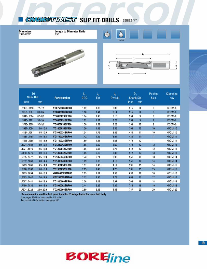
� SLIP FIT DRILLS - SERIES “Y”
D1 L1 L2 L3 D2 Pocket Clamping Nom. Dia Part Number DOC Ext Overall Shank Dia Size Key
inch mm inch mm
.2953-.3110 7,5-7,9 YD0750026SDR00 1.02 1.33 3.02 .315 8 8 KDCM-8
.3150-.3307 8,0-8,4 YD0800028SDR00 1.10 1.41 3.11 .315 8 8 KDCM-8
.3346-.3504 8,5-8,9 YD0850029SER00 1.14 1.45 3.15 .354 9 8 KDCM-8
.3543-.3701 9,0-9,4 YD0900031SER00 1.22 1.54 3.23 .354 9 9 KDCM-9
.3740-.3898 9,5-9,9 YD0950033SFR00 1.30 1.59 3.28 .394 10 9 KDCM-9
.3937-.4094 10,0-10,4 YD1000033SFR00 1.30 1.69 3.39 .394 10 10 KDCM-10
.4134-.4291 10,5-10,9 YD1050034SGR00 1.34 1.76 3.46 .433 11 10 KDCM-10
.4331-.4488 11,0-11,4 YD1100036SGR00 1.42 1.85 3.54 .433 11 11 KDCM-11
.4528-.4685 11,5-11,9 YD1150038SHR00 1.50 1.91 3.61 .472 12 11 KDCM-11.4724-.4882 12,0-12,4 YD1200042SHR00 1.65 2.00 3.69 .472 12 12 KDCM-12.4921-.5079 12,5-12,9 YD1250042SJR00 1.65 2.07 3.76 .512 13 12 KDCM-12.5118-.5276 13,0-13,4 YD1300042SJR00 1.65 2.15 3.92 .512 13 13 KDCM-13.5315-.5472 13,5-13,9 YD1350044SKR00 1.73 2.21 3.98 .551 14 13 KDCM-14.5512-.5669 14,0-14,4 YD1400048SKR00 1.89 2.33 4.10 .551 14 14 KDCM-14.5709-.5866 14,5-14,9 YD1450050SLR00 1.97 2.40 4.17 .591 15 14 KDCM-15.5906-.6260 15,0-15,9 YD1500052SLR00 2.05 2.49 4.26 .591 15 15 KDCM-15.6299-.6654 16,0-16,9 YD1600052SMR00 2.05 2.64 4.53 .630 16 16 KCDM-16.6693-.7047 17,0-17,9 YD1700055SNR00 2.17 2.90 4.79 .669 17 17 KDCM-17.7087-.7441 18,0-18,9 YD1800060SPR00 2.36 3.08 4.97 .709 18 18 KDCM-18.7480-.7835 19,0-19,9 YD1900062SQR00 2.44 3.22 5.35 .748 19 19 KDCM-19.7874-.8228 20,0-20,9 YD2000066SRR00 2.60 3.33 5.46 .787 20 20 KDCM-20
L2
L1
D1 D2
L3
Diameters Length to Diameter Ratio.2953-.8228" 3.5:1
Coolant
Do not mount a smaller drill point than the D1 range listed for each drill body.See pages 25-29 for replaceable drill points.For technical information, see page 102.
20
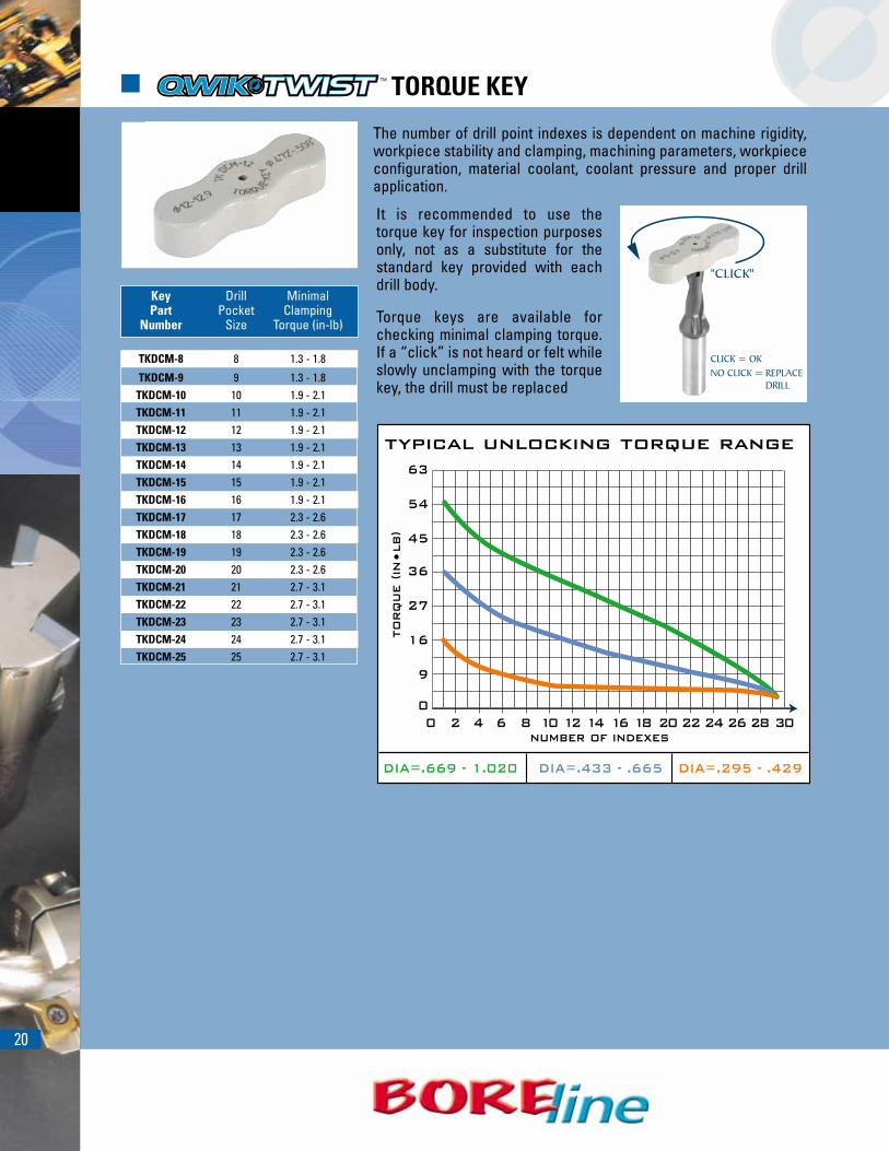
� TORQUE KEY
Key Drill MinimalPart Pocket Clamping
Number Size Torque (in-lb)
TKDCM-8 8 1.3 - 1.8
TKDCM-9 9 1.3 - 1.8TKDCM-10 10 1.9 - 2.1TKDCM-11 11 1.9 - 2.1TKDCM-12 12 1.9 - 2.1TKDCM-13 13 1.9 - 2.1TKDCM-14 14 1.9 - 2.1TKDCM-15 15 1.9 - 2.1TKDCM-16 16 1.9 - 2.1TKDCM-17 17 2.3 - 2.6TKDCM-18 18 2.3 - 2.6TKDCM-19 19 2.3 - 2.6TKDCM-20 20 2.3 - 2.6TKDCM-21 21 2.7 - 3.1TKDCM-22 22 2.7 - 3.1TKDCM-23 23 2.7 - 3.1TKDCM-24 24 2.7 - 3.1TKDCM-25 25 2.7 - 3.1
The number of drill point indexes is dependent on machine rigidity,workpiece stability and clamping, machining parameters, workpiececonfiguration, material coolant, coolant pressure and proper drillapplication.
It is recommended to use thetorque key for inspection purposesonly, not as a substitute for thestandard key provided with eachdrill body.
Torque keys are available forchecking minimal clamping torque.If a “click” is not heard or felt whileslowly unclamping with the torquekey, the drill must be replaced
21
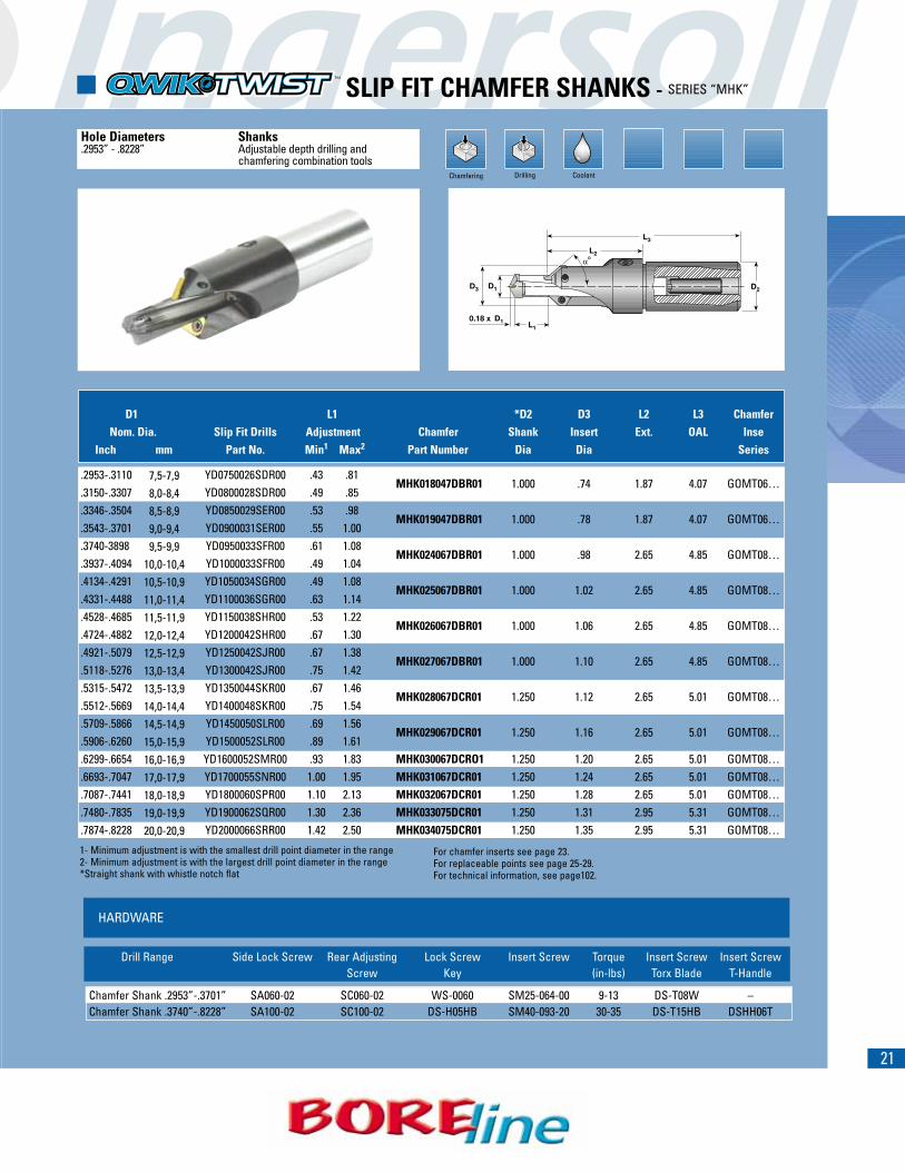
� SLIP FIT CHAMFER SHANKS - SERIES “MHK”
Chamfering
Hole Diameters Shanks.2953” - .8228” Adjustable depth drilling and
chamfering combination tools
D1 L1 *D2 D3 L2 L3 ChamferNom. Dia. Slip Fit Drills Adjustment Chamfer Shank Insert Ext. OAL Inse
Inch mm Part No. Min1 Max2 Part Number Dia Dia Series
.2953-.3110 YD0750026SDR00 .43 .81MHK018047DBR01 1.000 .74 1.87 4.07 GOMT06…
.3150-.3307 YD0800028SDR00 .49 .85
.3346-.3504 YD0850029SER00 .53 .98MHK019047DBR01 1.000 .78 1.87 4.07 GOMT06…
.3543-.3701 YD0900031SER00 .55 1.00
.3740-3898 YD0950033SFR00 .61 1.08MHK024067DBR01 1.000 .98 2.65 4.85 GOMT08…
.3937-.4094 YD1000033SFR00 .49 1.04
.4134-.4291 YD1050034SGR00 .49 1.08MHK025067DBR01 1.000 1.02 2.65 4.85 GOMT08…
.4331-.4488 YD1100036SGR00 .63 1.14
.4528-.4685 YD1150038SHR00 .53 1.22MHK026067DBR01 1.000 1.06 2.65 4.85 GOMT08…
.4724-.4882 YD1200042SHR00 .67 1.30
.4921-.5079 YD1250042SJR00 .67 1.38MHK027067DBR01 1.000 1.10 2.65 4.85 GOMT08…
.5118-.5276 YD1300042SJR00 .75 1.42
.5315-.5472 YD1350044SKR00 .67 1.46MHK028067DCR01 1.250 1.12 2.65 5.01 GOMT08…
.5512-.5669 YD1400048SKR00 .75 1.54
.5709-.5866 YD1450050SLR00 .69 1.56MHK029067DCR01 1.250 1.16 2.65 5.01 GOMT08…
.5906-.6260 YD1500052SLR00 .89 1.61
.6299-.6654 YD1600052SMR00 .93 1.83 MHK030067DCRO1 1.250 1.20 2.65 5.01 GOMT08…
.6693-.7047 YD1700055SNR00 1.00 1.95 MHK031067DCR01 1.250 1.24 2.65 5.01 GOMT08…
.7087-.7441 YD1800060SPR00 1.10 2.13 MHK032067DCR01 1.250 1.28 2.65 5.01 GOMT08…
.7480-.7835 YD1900062SQR00 1.30 2.36 MHK033075DCR01 1.250 1.31 2.95 5.31 GOMT08…
.7874-.8228 YD2000066SRR00 1.42 2.50 MHK034075DCR01 1.250 1.35 2.95 5.31 GOMT08…
7,5-7,98,0-8,48,5-8,99,0-9,49,5-9,9
10,0-10,410,5-10,911,0-11,411,5-11,912,0-12,412,5-12,913,0-13,413,5-13,914,0-14,414,5-14,915,0-15,916,0-16,917,0-17,918,0-18,919,0-19,920,0-20,9
1- Minimum adjustment is with the smallest drill point diameter in the range2- Minimum adjustment is with the largest drill point diameter in the range*Straight shank with whistle notch flat
HARDWARE
Drill Range Side Lock Screw Rear Adjusting Lock Screw Insert Screw Torque Insert Screw Insert ScrewScrew Key (in-lbs) Torx Blade T-Handle
Chamfer Shank .2953”-.3701” SA060-02 SC060-02 WS-0060 SM25-064-00 9-13 DS-T08W –Chamfer Shank .3740”-.8228” SA100-02 SC100-02 DS-H05HB SM40-093-20 30-35 DS-T15HB DSHH06T
For chamfer inserts see page 23.For replaceable points see page 25-29.For technical information, see page102.
Drilling Coolant

22
� TAP DRILL/CHAMFER COMBO - SERIES “Y”
D1 L1 L2 L3 L4 D2 D3Thread Nom Nom Body General D1 Full Full Ext OAL Shank Shank Chamfer Pocket Clamping
Size Point Point Number Purpose Point Dia to Dia to Dia Dia Dia Size KeySize Size Drill Point Range Chamfer Top of mmInch mm Chamfer
M8 .2677 6,8 YC0680021SKR00 YAB0680R01 .2677 .2913 .827 .972 1.650 3.42 14 .551 .547 6,8 KDCM-8M10 .3346 8,5 YC0830026SKR00 YAB0850R01 .3268 .3504 1.024 1.138 1.831 3.60 14 .551 .551 8 KDCM-8M12 .4016 10,2 YC1000030SKR00 YAB1020R01 .3937 .4291 1.181 1.264 2.047 3.82 14 .551 .551 10 KDCM-10M14 .4724 12,0 YC1200035SMR00 YAB1200R01 .4724 .5079 1.378 1.465 2.283 4.17 16 .630 .630 12 KDCM-12M16 .5512 14,0 YC1400039SPR00 YAB1400R01 .5512 .5866 1.535 1.622 2.362 4.25 18 .709 .709 14 KDCM-14M20 .6890 17,5 YC1730042SRR00 YAB1750R01 .6811 .7047 1.654 1.728 2.480 4.45 20 .787 .827 17 KDCM-17M24 .8268 21,0 YC2100048SSR00 YAB2100R01 .8268 .8622 1.890 1.984 2.677 4.88 25 .984 1.004 21 KDCM-21
D1 L1 L2 L3 L4 D2 D3Thread Nom Nom Body General D1 Full Full Ext OAL Shank Shank Chamfer Pocket Clamping
Size Point Point Number Purpose Point Dia to Dia to Dia Dia Dia Size KeySize Size Drill Point Range Chamfer Top of mm InchInch mm Chamfer
3/8 UNC .3110 7,9 YC0770025RHR01 YAB0790R01 .3031 .3110 1.00 1.15 1.80 3.69 .625 15.88 .59 8 KDCM-83/8 UNF .3346 8,5 YC0820025RHR01 YAB0850R01 .3228 .3504 1.00 1.15 1.80 3.69 .625 15.88 .61 8 KDCM-87/16 UNC .3701 9,4 YC0910026RHR01 YAB0940R01 .3583 .3898 1.06 1.20 1.83 3.72 .625 15.88 .63 9 KDCM-97/16 UNF .3898 9,9 YC0910026RHR01 YAB0990R01 .3819 .3898 1.06 1.18 1.82 3.71 .625 15.88 .63 9 KDCM-91/2 UNC .4252 10,8 YC1050026RHR01 YAB1080R01 .4134 .4291 1.06 1.17 1.89 3.78 .625 15.88 .63 10 KDCM-101/2 UNF .4528 11,5 YC1130026RHR01 YAB1150R01 .4449 .4685 1.06 1.15 1.89 3.78 .625 15.88 .63 11 KDCM-119/16 UNC .4843 12,3 YC1210026RHR01 YAB1230R01 .4764 .5079 1.06 1.14 1.89 3.78 .625 15.88 .63 12 KDCM-129/16 UNF .5118 13,0 YC1300026RHR01 YAB1300R01 .5118 .5472 1.06 1.12 1.89 3.78 .625 15.88 .63 13 KDCM-135/8 UNC .5394 13,7 YC1330030RJR01 YAB1370R01 .5236 .5472 1.20 1.32 2.01 3.98 .750 19.05 .75 13 KDCM-135/8 UNF .5748 14,6 YC1450030RJR01 YAB1460R01 .5709 .5866 1.20 1.29 2.03 4.00 .750 19.05 .75 14 KDCM-143/4 UNC .6575 16,7 YC1650035RJR01 YAB1670R01 .6496 .6654 1.40 1.47 2.20 4.17 .750 19.05 .78 16 KDCM-163/4 UNF .6890 17,5 YC1730035RLR01 YAB1750R01 .6811 .7047 1.40 1.50 2.20 4.40 1.000 25.40 .88 17 KDCM-177/8 UNC .7677 19,5 YC1920041RLR01 YAB1950R01 .7559 .7835 1.65 1.78 2.48 4.68 1.000 25.40 1.00 19 KDCM-197/8 UNF .8071 20,5 YC2040041RLR01 YAB2050R01 .8031 .8228 1.65 1.75 2.48 4.68 1.000 25.40 1.00 20 KDCM-20
Chamfering
Tap Drills Combine tap drilling and chamferingM8-M24 in one operation.UNC/UNF 3/8”-7/8”
For chamfer inserts see page 23. For replaceable points see page 25-29. For technical information, see page 102.
Reduce recommended feed for M8 drill by 10%.
Drilling Coolant
Metric
Inch
HARDWARE
Chamfering Insert Screw Chamfering Insert Screw Key Torque (in-lbs)
SM22-046-00 DS-T07F 7-11
23
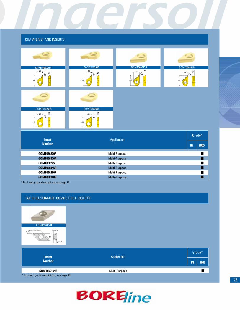
CHAMFER SHANK INSERTS
TAP DRILL/CHAMFER COMBO DRILL INSERTS
.48
30˚
.25.11
GOMT060230R
.63
30˚
.35.13
GOMT080330R
.63
.45˚
.35.13
.48
60˚
.25.11
.63
60˚
.35.13
GOMT080360R
.223
.177
.085
.077 ± .001
.45.5˚
KOMT050104R
.48
.45˚
.25.11
GOMT060245R
Insert ApplicationNumber IN 2005
GOMT060230R Multi-PurposeGOMT080330R Multi-PurposeGOMT060245R Multi-PurposeGOMT080345R Multi-PurposeGOMT060260R Multi-PurposeGOMT080360R Multi-Purpose
�
�
�
�
�
�
* For insert grade descriptions, see page 86.
Grade*
GOMT080345R
GOMT060260R
Insert ApplicationNumber IN 1505
KOMT050104R Multi-Purpose* For insert grade descriptions, see page 86.
Grade*
�
24For technical information, see pages 100-101.
INSERTS & HARDWARE
ZOMW090700R
Insert ApplicationNumber IN 1530
ZOMW090700R Multi-Purpose �
* For insert grade descriptions, see page 86.
Grade*
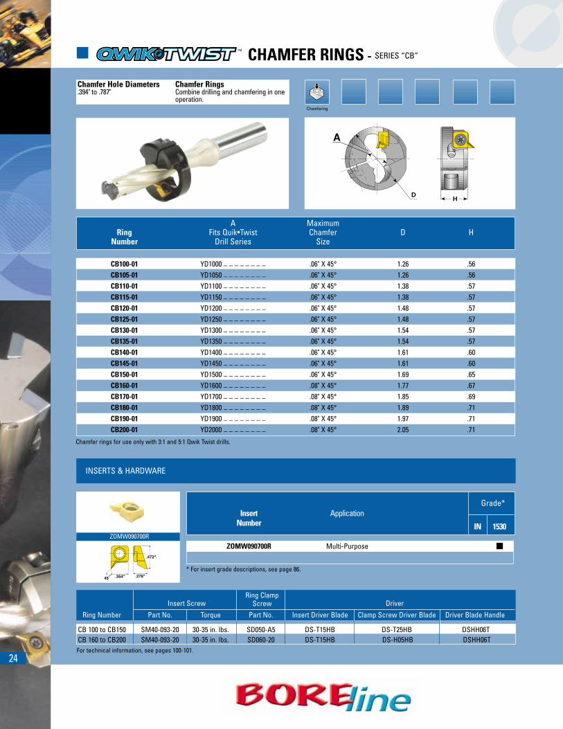
� CHAMFER RINGS - SERIES “CB”
Chamfering
Chamfer Hole Diameters Chamfer Rings.394" to .787" Combine drilling and chamfering in one
operation.
HD
A MaximumRing Fits Quik•Twist Chamfer D H
Number Drill Series Size
CB100-01 YD1000 _ _ _ _ _ _ _ _ .06" X 45° 1.26 .56CB105-01 YD1050 _ _ _ _ _ _ _ _ .06" X 45° 1.26 .56CB110-01 YD1100 _ _ _ _ _ _ _ _ .06" X 45° 1.38 .57CB115-01 YD1150 _ _ _ _ _ _ _ _ .06" X 45° 1.38 .57CB120-01 YD1200 _ _ _ _ _ _ _ _ .06" X 45° 1.48 .57CB125-01 YD1250 _ _ _ _ _ _ _ _ .06" X 45° 1.48 .57CB130-01 YD1300 _ _ _ _ _ _ _ _ .06" X 45° 1.54 .57CB135-01 YD1350 _ _ _ _ _ _ _ _ .06" X 45° 1.54 .57CB140-01 YD1400 _ _ _ _ _ _ _ _ .06" X 45° 1.61 .60CB145-01 YD1450 _ _ _ _ _ _ _ _ .06" X 45° 1.61 .60CB150-01 YD1500 _ _ _ _ _ _ _ _ .06" X 45° 1.69 .65CB160-01 YD1600 _ _ _ _ _ _ _ _ .08" X 45° 1.77 .67CB170-01 YD1700 _ _ _ _ _ _ _ _ .08" X 45° 1.85 .69CB180-01 YD1800 _ _ _ _ _ _ _ _ .08" X 45° 1.89 .71CB190-01 YD1900 _ _ _ _ _ _ _ _ .08" X 45° 1.97 .71CB200-01 YD2000 _ _ _ _ _ _ _ _ .08" X 45° 2.05 .71
Chamfer rings for use only with 3:1 and 5:1 Qwik Twist drills.
Ring Number Part No. Torque Part No. Insert Driver Blade Clamp Screw Driver Blade Driver Blade Handle
CB 100 to CB150 SM40-093-20 30-35 in. lbs. SD050-A5 DS-T15HB DS-T25HB DSHH06TCB 160 to CB200 SM40-093-20 30-35 in. lbs. SD060-20 DS-T15HB DS-H05HB DSHH06T
Insert ScrewRing Clamp
Screw Driver
25
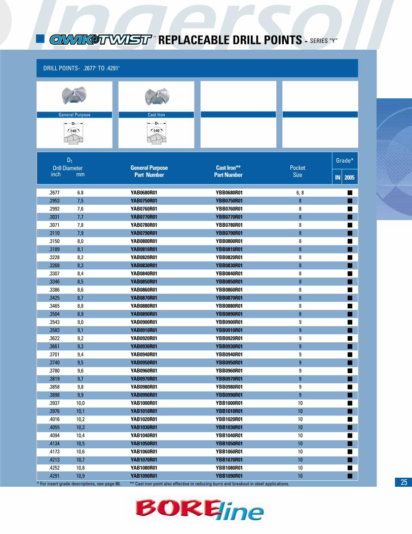
DRILL POINTS- .2677" TO .4291"
General Purpose Cast Iron
D1Drill Diameter General Purpose Cast Iron** Pocket
inch mm Part Number Part Number Size IN 2005
.2677 6.8 YAB0680R01 YBB0680R01 6, 8
.2953 7,5 YAB0750R01 YBB0750R01 8
.2992 7,6 YAB0760R01 YBB0760R01 8
.3031 7,7 YAB0770R01 YBB0770R01 8
.3071 7,8 YAB0780R01 YBB0780R01 8
.3110 7,9 YAB0790R01 YBB0790R01 8
.3150 8,0 YAB0800R01 YBB0800R01 8
.3189 8,1 YAB0810R01 YBB0810R01 8
.3228 8,2 YAB0820R01 YBB0820R01 8
.3268 8,3 YAB0830R01 YBB0830R01 8
.3307 8,4 YAB0840R01 YBB0840R01 8
.3346 8,5 YAB0850R01 YBB0850R01 8
.3386 8,6 YAB0860R01 YBB0860R01 8
.3425 8,7 YAB0870R01 YBB0870R01 8
.3465 8,8 YAB0880R01 YBB0880R01 8
.3504 8,9 YAB0890R01 YBB0890R01 8
.3543 9,0 YAB0900R01 YBB0900R01 9
.3583 9,1 YAB0910R01 YBB0910R01 9
.3622 9,2 YAB0920R01 YBB0920R01 9
.3661 9,3 YAB0930R01 YBB0930R01 9
.3701 9,4 YAB0940R01 YBB0940R01 9
.3740 9,5 YAB0950R01 YBB0950R01 9
.3780 9,6 YAB0960R01 YBB0960R01 9
.3819 9,7 YAB0970R01 YBB0970R01 9
.3858 9,8 YAB0980R01 YBB0980R01 9
.3898 9,9 YAB0990R01 YBB0990R01 9
.3937 10,0 YAB1000R01 YBB1000R01 10
.3976 10,1 YAB1010R01 YBB1010R01 10
.4016 10,2 YAB1020R01 YBB1020R01 10
.4055 10,3 YAB1030R01 YBB1030R01 10
.4094 10,4 YAB1040R01 YBB1040R01 10
.4134 10,5 YAB1050R01 YBB1050R01 10
.4173 10,6 YAB1060R01 YBB1060R01 10
.4213 10,7 YAB1070R01 YBB1070R01 10
.4252 10,8 YAB1080R01 YBB1080R01 10
.4291 10,9 YAB1090R01 YBB1090R01 10
�
�
�
�
�
�
�
�
�
�
�
�
�
�
�
�
�
�
�
�
�
�
�
�
�
�
�
�
�
�
�
�
�
�
�
�
� REPLACEABLE DRILL POINTS - SERIES “Y”
* For insert grade descriptions, see page 86. ** Cast iron point also effective in reducing burrs and breakout in steel applications.
Grade*
26
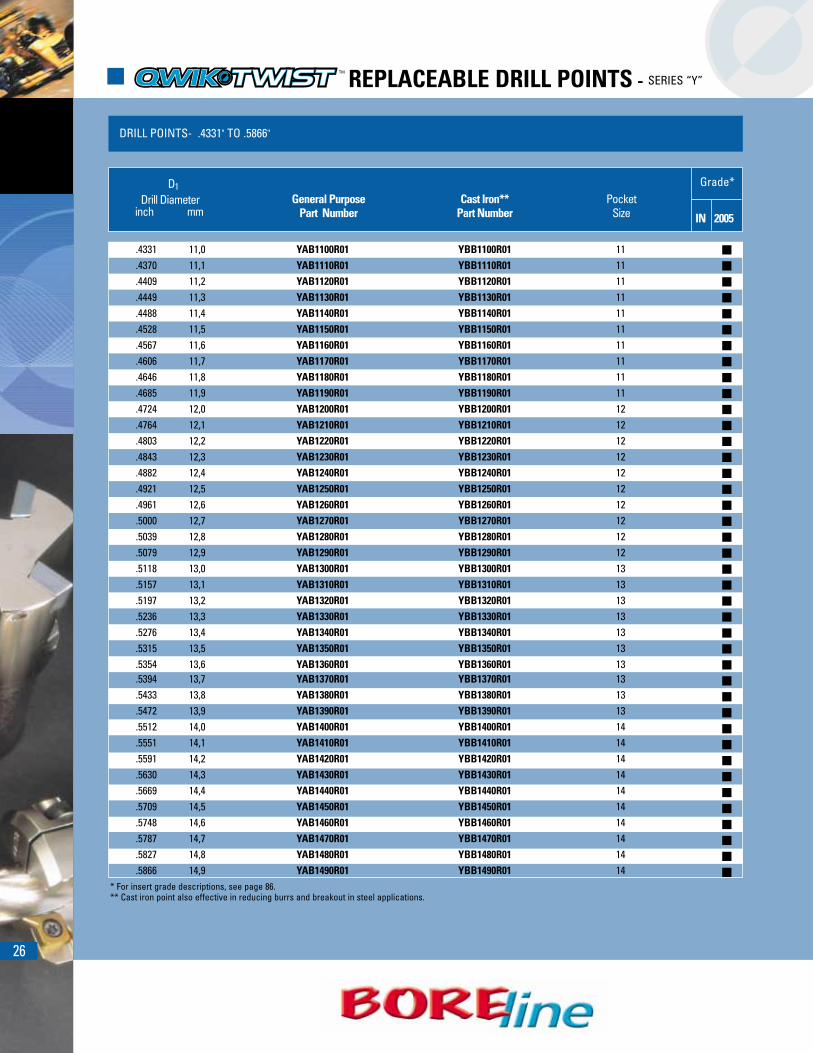
� REPLACEABLE DRILL POINTS - SERIES “Y”
DRILL POINTS- .4331" TO .5866"
�
�
�
�
�
�
�
�
�
�
�
�
�
�
�
�
�
�
�
�
�
�
�
�
�
�
�
�
�
�
�
�
�
�
�
�
�
�
�
�
Grade*D1Drill Diameter General Purpose Cast Iron** Pocket
inch mm Part Number Part Number Size IN 2005
.4331 11,0 YAB1100R01 YBB1100R01 11
.4370 11,1 YAB1110R01 YBB1110R01 11
.4409 11,2 YAB1120R01 YBB1120R01 11
.4449 11,3 YAB1130R01 YBB1130R01 11
.4488 11,4 YAB1140R01 YBB1140R01 11
.4528 11,5 YAB1150R01 YBB1150R01 11
.4567 11,6 YAB1160R01 YBB1160R01 11
.4606 11,7 YAB1170R01 YBB1170R01 11
.4646 11,8 YAB1180R01 YBB1180R01 11
.4685 11,9 YAB1190R01 YBB1190R01 11
.4724 12,0 YAB1200R01 YBB1200R01 12
.4764 12,1 YAB1210R01 YBB1210R01 12
.4803 12,2 YAB1220R01 YBB1220R01 12
.4843 12,3 YAB1230R01 YBB1230R01 12
.4882 12,4 YAB1240R01 YBB1240R01 12
.4921 12,5 YAB1250R01 YBB1250R01 12
.4961 12,6 YAB1260R01 YBB1260R01 12
.5000 12,7 YAB1270R01 YBB1270R01 12
.5039 12,8 YAB1280R01 YBB1280R01 12
.5079 12,9 YAB1290R01 YBB1290R01 12
.5118 13,0 YAB1300R01 YBB1300R01 13
.5157 13,1 YAB1310R01 YBB1310R01 13
.5197 13,2 YAB1320R01 YBB1320R01 13
.5236 13,3 YAB1330R01 YBB1330R01 13
.5276 13,4 YAB1340R01 YBB1340R01 13
.5315 13,5 YAB1350R01 YBB1350R01 13
.5354 13,6 YAB1360R01 YBB1360R01 13
.5394 13,7 YAB1370R01 YBB1370R01 13
.5433 13,8 YAB1380R01 YBB1380R01 13
.5472 13,9 YAB1390R01 YBB1390R01 13
.5512 14,0 YAB1400R01 YBB1400R01 14
.5551 14,1 YAB1410R01 YBB1410R01 14
.5591 14,2 YAB1420R01 YBB1420R01 14
.5630 14,3 YAB1430R01 YBB1430R01 14
.5669 14,4 YAB1440R01 YBB1440R01 14
.5709 14,5 YAB1450R01 YBB1450R01 14
.5748 14,6 YAB1460R01 YBB1460R01 14
.5787 14,7 YAB1470R01 YBB1470R01 14
.5827 14,8 YAB1480R01 YBB1480R01 14
.5866 14,9 YAB1490R01 YBB1490R01 14* For insert grade descriptions, see page 86.** Cast iron point also effective in reducing burrs and breakout in steel applications.

27
DRILL POINTS- .5906" TO .7441"
�
�
�
�
�
�
�
�
�
�
�
�
�
�
�
�
�
�
�
�
�
�
�
�
�
�
�
�
�
�
�
�
�
�
�
�
�
�
��
D1Drill Diameter General Purpose Cast Iron** Pocket
inch mm Part Number Part Number Size IN 2005
.5906 15,0 YAB1500R01 YBB1500R01 15
.5945 15,1 YAB1510R01 YBB1510R01 15
.5984 15,2 YAB1520R01 YBB1520R01 15
.6024 15,3 YAB1530R01 YBB1530R01 15
.6063 15,4 YAB1540R01 YBB1540R01 15
.6102 15,5 YAB1550R01 YBB1550R01 15
.6142 15,6 YAB1560R01 YBB1560R01 15
.6181 15,7 YAB1570R01 YBB1570R01 15
.6220 15,8 YAB1580R01 YBB1580R01 15
.6260 15,9 YAB1590R01 YBB1590R01 15
.6299 16,0 YAB1600R01 YBB1600R01 16
.6339 16,1 YAB1610R01 YBB1610R01 16
.6378 16,2 YAB1620R01 YBB1620R01 16
.6417 16,3 YAB1630R01 YBB1630R01 16
.6457 16,4 YAB1640R01 YBB1640R01 16
.6496 16,5 YAB1650R01 YBB1650R01 16
.6535 16,6 YAB1660R01 YBB1660R01 16
.6575 16,7 YAB1670R01 YBB1670R01 16
.6614 16,8 YAB1680R01 YBB1680R01 16
.6654 16,9 YAB1690R01 YBB1690R01 16
.6693 17,0 YAB1700R01 YBB1700R01 17
.6732 17,1 YAB1710R01 YBB1710R01 17
.6772 17,2 YAB1720R01 YBB1720R01 17
.6811 17,3 YAB1730R01 YBB1730R01 17
.6850 17,4 YAB1740R01 YBB1740R01 17
.6890 17,5 YAB1750R01 YBB1750R01 17
.6929 17,6 YAB1760R01 YBB1760R01 17
.6968 17,7 YAB1770R01 YBB1770R01 17
.7008 17,8 YAB1780R01 YBB1780R01 17
.7047 17,9 YAB1790R01 YBB1790R01 17
.7087 18,0 YAB1800R01 YBB1800R01 18
.7126 18,1 YAB1810R01 YBB1810R01 18
.7165 18,2 YAB1820R01 YBB1820R01 18
.7205 18,3 YAB1830R01 YBB1830R01 18
.7244 18,4 YAB1840R01 YBB1840R01 18
.7283 18,5 YAB1850R01 YBB1850R01 18
.7323 18,6 YAB1860R01 YBB1860R01 18
.7362 18,7 YAB1870R01 YBB1870R01 18
.7402 18,8 YAB1880R01 YBB1880R01 18
.7441 18,9 YAB1890R01 YBB1890R01 18* For insert grade descriptions, see page 86.** Cast iron point also effective in reducing burrs and breakout in steel applications.
Grade*

28
� REPLACEABLE DRILL POINTS - SERIES “Y”
DRILL POINTS- .7480" TO .9016"
�
�
�
�
�
�
�
�
�
�
�
�
�
�
�
�
�
�
�
�
�
�
�
�
�
�
�
�
�
�
�
�
�
�
�
�
�
�
�
�
�
�
D1Drill Diameter General Purpose Cast Iron** Pocket
inch mm Part Number Part Number Size IN 2005
.7480 19,0 YAB1900R01 YBB1900R01 19
.7500 19,05 YAB1905R01 YBB1905R01 19
.7520 19,1 YAB1910R01 YBB1910R01 19
.7559 19,2 YAB1920R01 YBB1920R01 19
.7598 19,3 YAB1930R01 YBB1930R01 19
.7638 19,4 YAB1940R01 YBB1940R01 19
.7677 19,5 YAB1950R01 YBB1950R01 19
.7717 19,6 YAB1960R01 YBB1960R01 19
.7756 19,7 YAB1970R01 YBB1970R01 19
.7795 19,8 YAB1980R01 YBB1980R01 19
.7835 19,9 YAB1990R01 YBB1990R01 19
.7874 20,0 YAB2000R01 YBB2000R01 20
.7913 20,1 YAB2010R01 YBB2010R01 20
.7953 20,2 YAB2020R01 YBB2020R01 20
.7992 20,3 YAB2030R01 YBB2030R01 20
.8031 20,4 YAB2040R01 YBB2040R01 20
.8071 20,5 YAB2050R01 YBB2050R01 20
.8110 20,6 YAB2060R01 YBB2060R01 20
.8150 20,7 YAB2070R01 YBB2070R01 20
.8189 20,8 YAB2080R01 YBB2080R01 20
.8228 20,9 YAB2090R01 YBB2090R01 20
.8268 21,0 YAB2100R01 YBB2100R01 21
.8307 21,1 YAB2110R01 YBB2110R01 21
.8346 21,2 YAB2120R01 YBB2120R01 21
.8386 21,3 YAB2130R01 YBB2130R01 21
.8425 21,4 YAB2140R01 YBB2140R01 21
.8465 21,5 YAB2150R01 YBB2150R01 21
.8504 21,6 YAB2160R01 YBB2160R01 21
.8543 21,7 YAB2170R01 YBB2170R01 21
.8583 21,8 YAB2180R01 YBB2180R01 21
.8622 21,9 YAB2190R01 YBB2190R01 21
.8661 22,0 YAB2200R01 YBB2200R01 22
.8701 22,1 YAB2210R01 YBB2210R01 22
.8740 22,2 YAB2220R01 YBB2220R01 22
.8750 22,22 YAB2222R01 YBB2222R01 22
.8780 22,3 YAB2230R01 YBB2230R01 22
.8819 22,4 YAB2240R01 YBB2240R01 22
.8858 22,5 YAB2250R01 YBB2250R01 22
.8898 22,6 YAB2260R01 YBB2260R01 22
.8937 22,7 YAB2270R01 YBB2270R01 22
.8976 22,8 YAB2280R01 YBB2280R01 22
.9016 22,9 YAB2290R01 YBB2290R01 22** Cast iron point also effective in reducing burrs and breakout in steel applications.
Grade*
29
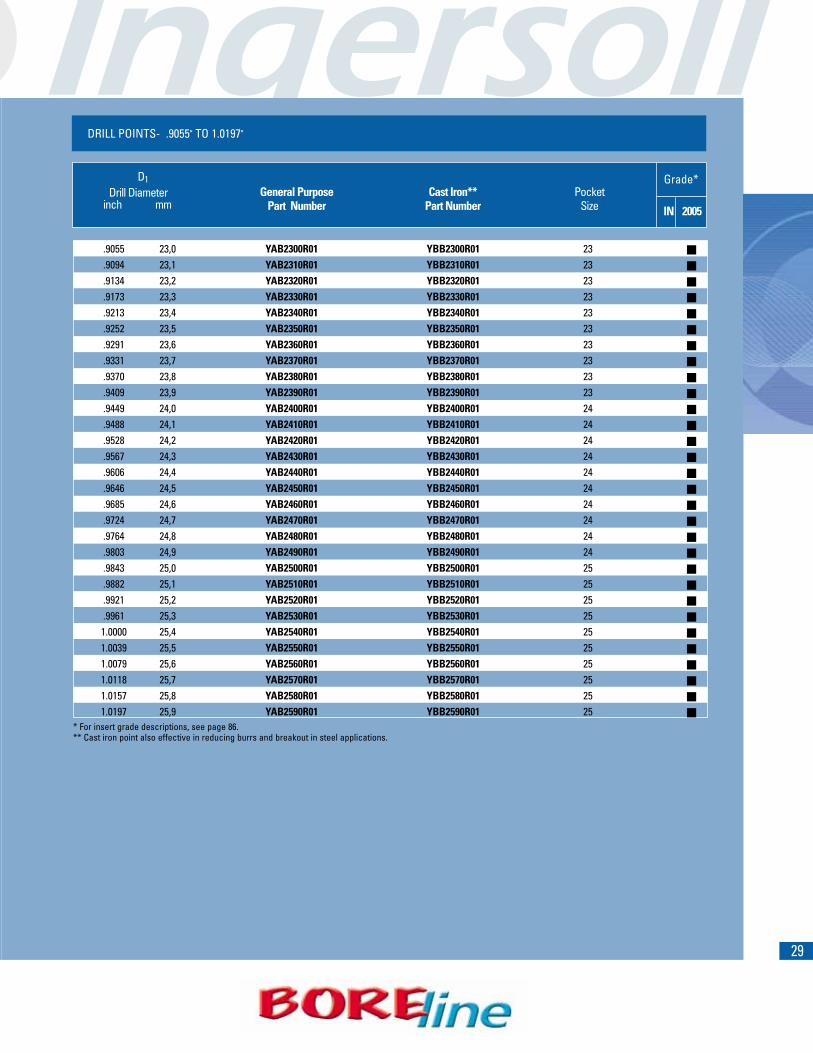
DRILL POINTS- .9055" TO 1.0197"
�
�
�
�
�
�
�
�
�
�
�
�
�
�
�
�
�
�
�
�
�
�
�
�
�
�
�
�
�
�
D1Drill Diameter General Purpose Cast Iron** Pocket
inch mm Part Number Part Number Size IN 2005
.9055 23,0 YAB2300R01 YBB2300R01 23
.9094 23,1 YAB2310R01 YBB2310R01 23
.9134 23,2 YAB2320R01 YBB2320R01 23
.9173 23,3 YAB2330R01 YBB2330R01 23
.9213 23,4 YAB2340R01 YBB2340R01 23
.9252 23,5 YAB2350R01 YBB2350R01 23
.9291 23,6 YAB2360R01 YBB2360R01 23
.9331 23,7 YAB2370R01 YBB2370R01 23
.9370 23,8 YAB2380R01 YBB2380R01 23
.9409 23,9 YAB2390R01 YBB2390R01 23
.9449 24,0 YAB2400R01 YBB2400R01 24
.9488 24,1 YAB2410R01 YBB2410R01 24
.9528 24,2 YAB2420R01 YBB2420R01 24
.9567 24,3 YAB2430R01 YBB2430R01 24
.9606 24,4 YAB2440R01 YBB2440R01 24
.9646 24,5 YAB2450R01 YBB2450R01 24
.9685 24,6 YAB2460R01 YBB2460R01 24
.9724 24,7 YAB2470R01 YBB2470R01 24
.9764 24,8 YAB2480R01 YBB2480R01 24
.9803 24,9 YAB2490R01 YBB2490R01 24
.9843 25,0 YAB2500R01 YBB2500R01 25
.9882 25,1 YAB2510R01 YBB2510R01 25
.9921 25,2 YAB2520R01 YBB2520R01 25
.9961 25,3 YAB2530R01 YBB2530R01 251.0000 25,4 YAB2540R01 YBB2540R01 251.0039 25,5 YAB2550R01 YBB2550R01 251.0079 25,6 YAB2560R01 YBB2560R01 251.0118 25,7 YAB2570R01 YBB2570R01 251.0157 25,8 YAB2580R01 YBB2580R01 251.0197 25,9 YAB2590R01 YBB2590R01 25
* For insert grade descriptions, see page 86.** Cast iron point also effective in reducing burrs and breakout in steel applications.
Grade*

30
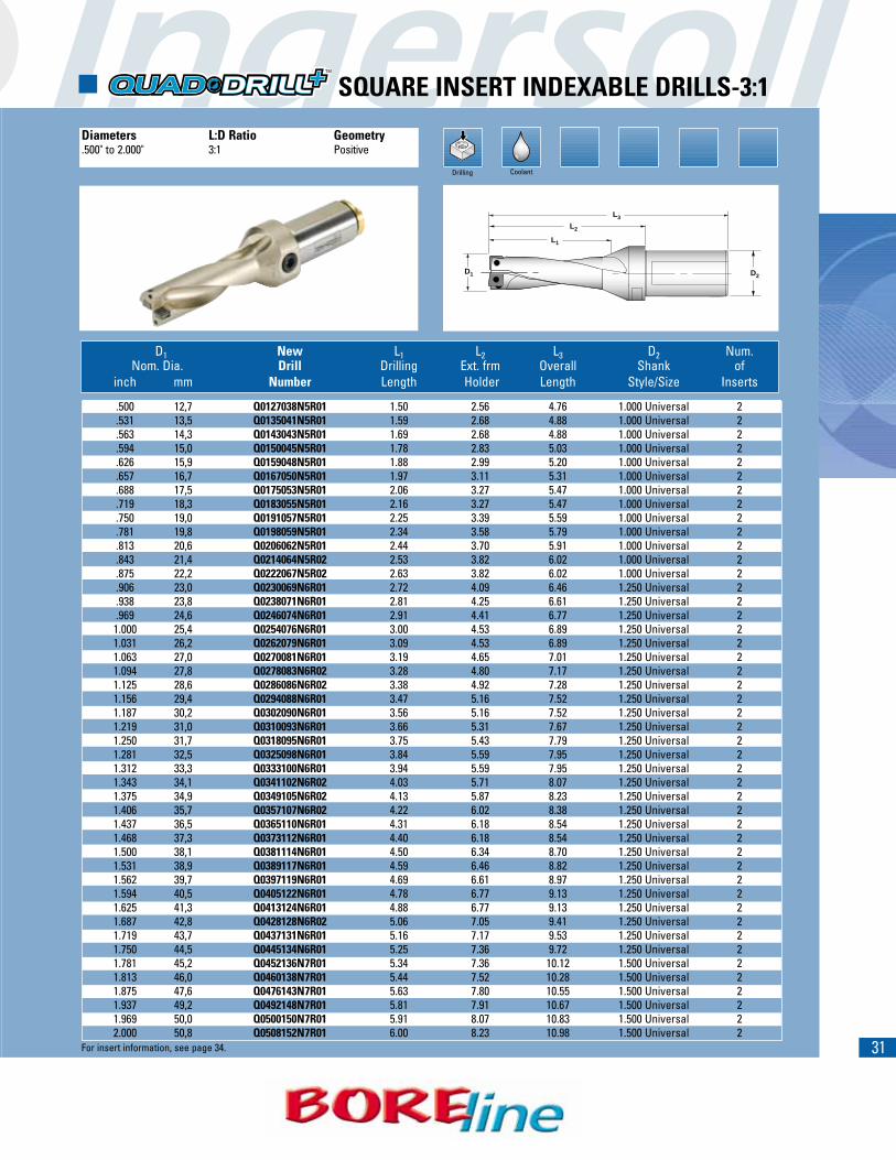
Drilling Coolant
D1 New L1 L2 L3 D2 Num.Nom. Dia. Drill Drilling Ext. frm Overall Shank of
inch mm Number Length Holder Length Style/Size Inserts
.500 12,7 Q0127025N5R01 1.00 2.05 4.25 1.000 Universal 2
.531 13,5 Q0135027N5R01 1.06 2.13 4.33 1.000 Universal 2
.563 14,3 Q0143029N5R01 1.13 2.13 4.33 1.000 Universal 2
.594 15,0 Q0150030N5R01 1.19 2.24 4.44 1.000 Universal 2
.625 15,9 Q0159032N5R01 1.25 2.36 4.57 1.000 Universal 2
.657 16,7 Q0167033N5R01 1.31 2.44 4.65 1.000 Universal 2
.688 17,5 Q0175035N5R01 1.38 2.56 4.76 1.000 Universal 2
.719 18,3 Q0183037N5R01 1.44 2.56 4.76 1.000 Universal 2
.750 19,0 Q0191038N5R01 1.50 2.64 4.84 1.000 Universal 2
.781 19,8 Q0198040N5R01 1.56 2.80 5.00 1.000 Universal 2
.813 20,6 Q0206041N5R01 1.63 2.87 5.08 1.000 Universal 2
.843 21,4 Q0214042N5R02 1.69 2.95 5.16 1.000 Universal 2
.875 22,2 Q0222044N5R02 1.75 2.95 5.16 1.000 Universal 2
.906 23,0 Q0230046N6R01 1.81 3.19 5.55 1.250 Universal 2
.938 23,8 Q0238048N6R01 1.88 3.31 5.67 1.250 Universal 2
.969 24,6 Q0246049N6R01 1.94 3.43 5.79 1.250 Universal 21.000 25,4 Q0254051N6R01 2.00 3.50 5.87 1.250 Universal 21.031 26,2 Q0262052N6R01 2.06 3.50 5.87 1.250 Universal 21.063 27,0 Q0270054N6R01 2.13 3.58 5.94 1.250 Universal 21.094 27,8 Q0278056N6R02 2.19 3.70 6.06 1.250 Universal 21.125 28,6 Q0286057N6R02 2.25 3.78 6.14 1.250 Universal 21.156 29,4 Q0294059N6R01 2.31 3.98 6.34 1.250 Universal 21.187 30,2 Q0302060N6R01 2.37 3.98 6.34 1.250 Universal 21.219 31,0 Q0310062N6R01 2.44 4.09 6.45 1.250 Universal 21.250 31,7 Q0318063N6R01 2.50 4.17 6.53 1.250 Universal 21.281 32,5 Q0325065N6R01 2.56 4.29 6.65 1.250 Universal 21.312 33,3 Q0333067N6R01 2.62 4.29 6.65 1.250 Universal 21.343 34,1 Q0341068N6R02 2.69 4.37 6.73 1.250 Universal 21.375 34,9 Q0349070N6R02 2.75 4.49 6.85 1.250 Universal 21.406 35,7 Q0357071N6R02 2.81 4.61 6.97 1.250 Universal 21.437 36,5 Q0365073N6R01 2.87 4.72 7.08 1.250 Universal 21.468 37,3 Q0373075N6R01 2.94 4.72 7.08 1.250 Universal 21.500 38,1 Q0381076N6R01 3.00 4.84 7.20 1.250 Universal 21.531 38,9 Q0389078N6R01 3.06 4.92 7.28 1.250 Universal 21.562 39,7 Q0397079N6R01 3.12 5.04 7.40 1.250 Universal 21.594 40,5 Q0405081N6R01 3.19 5.16 7.52 1.250 Universal 21.625 41,3 Q0413083N6R01 3.25 5.16 7.52 1.250 Universal 21.687 42,8 Q0428086N6R02 3.37 5.35 7.71 1.250 Universal 21.719 43,7 Q0437087N6R01 3.44 5.43 7.79 1.250 Universal 21.750 44,5 Q0445089N6R01 3.50 5.59 7.95 1.250 Universal 21.781 45,2 Q0452090N7R01 3.56 5.59 8.35 1.500 Universal 21.813 46,0 Q0460092N7R01 3.63 5.71 8.46 1.500 Universal 21.875 47,6 Q0476095N7R01 3.75 5.91 8.66 1.500 Universal 21.937 49,2 Q0492098N7R01 3.87 5.98 8.74 1.500 Universal 21.969 50,0 Q0500100N7R01 3.94 6.10 8.86 1.500 Universal 22.000 50,8 Q0508102N7R01 4.00 6.22 8.98 1.500 Universal 2
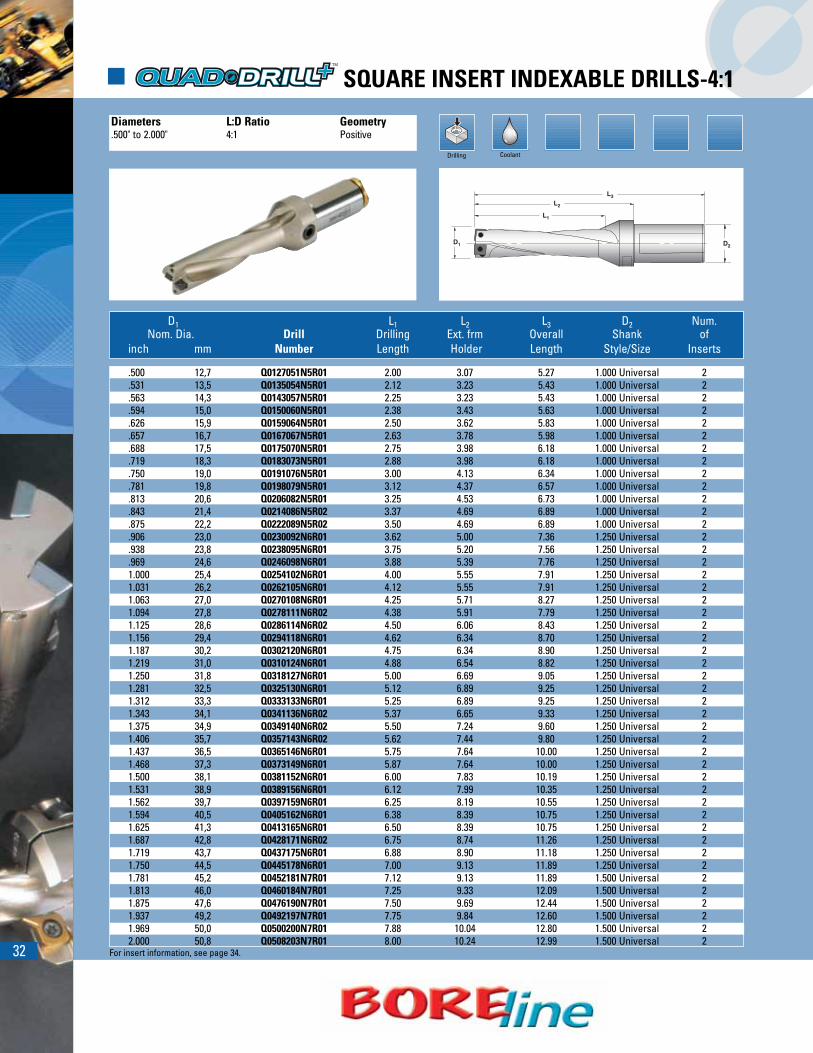
� SQUARE INSERT INDEXABLE DRILLS-2:1
Diameters L:D Ratio Geometry.500" to 2.000" 2:1 Positive
L1
D1 D2
L2
L3
For insert information, see page 34.
31
Drilling Coolant
� SQUARE INSERT INDEXABLE DRILLS-3:1
Diameters L:D Ratio Geometry.500" to 2.000" 3:1 Positive
L1
D1 D2
L2
L3
D1 New L1 L2 L3 D2 Num.Nom. Dia. Drill Drilling Ext. frm Overall Shank of
inch mm Number Length Holder Length Style/Size Inserts
.500 12,7 Q0127038N5R01 1.50 2.56 4.76 1.000 Universal 2
.531 13,5 Q0135041N5R01 1.59 2.68 4.88 1.000 Universal 2
.563 14,3 Q0143043N5R01 1.69 2.68 4.88 1.000 Universal 2
.594 15,0 Q0150045N5R01 1.78 2.83 5.03 1.000 Universal 2
.626 15,9 Q0159048N5R01 1.88 2.99 5.20 1.000 Universal 2
.657 16,7 Q0167050N5R01 1.97 3.11 5.31 1.000 Universal 2
.688 17,5 Q0175053N5R01 2.06 3.27 5.47 1.000 Universal 2
.719 18,3 Q0183055N5R01 2.16 3.27 5.47 1.000 Universal 2
.750 19,0 Q0191057N5R01 2.25 3.39 5.59 1.000 Universal 2
.781 19,8 Q0198059N5R01 2.34 3.58 5.79 1.000 Universal 2
.813 20,6 Q0206062N5R01 2.44 3.70 5.91 1.000 Universal 2
.843 21,4 Q0214064N5R02 2.53 3.82 6.02 1.000 Universal 2
.875 22,2 Q0222067N5R02 2.63 3.82 6.02 1.000 Universal 2
.906 23,0 Q0230069N6R01 2.72 4.09 6.46 1.250 Universal 2
.938 23,8 Q0238071N6R01 2.81 4.25 6.61 1.250 Universal 2
.969 24,6 Q0246074N6R01 2.91 4.41 6.77 1.250 Universal 21.000 25,4 Q0254076N6R01 3.00 4.53 6.89 1.250 Universal 21.031 26,2 Q0262079N6R01 3.09 4.53 6.89 1.250 Universal 21.063 27,0 Q0270081N6R01 3.19 4.65 7.01 1.250 Universal 21.094 27,8 Q0278083N6R02 3.28 4.80 7.17 1.250 Universal 21.125 28,6 Q0286086N6R02 3.38 4.92 7.28 1.250 Universal 21.156 29,4 Q0294088N6R01 3.47 5.16 7.52 1.250 Universal 21.187 30,2 Q0302090N6R01 3.56 5.16 7.52 1.250 Universal 21.219 31,0 Q0310093N6R01 3.66 5.31 7.67 1.250 Universal 21.250 31,7 Q0318095N6R01 3.75 5.43 7.79 1.250 Universal 21.281 32,5 Q0325098N6R01 3.84 5.59 7.95 1.250 Universal 21.312 33,3 Q0333100N6R01 3.94 5.59 7.95 1.250 Universal 21.343 34,1 Q0341102N6R02 4.03 5.71 8.07 1.250 Universal 21.375 34,9 Q0349105N6R02 4.13 5.87 8.23 1.250 Universal 21.406 35,7 Q0357107N6R02 4.22 6.02 8.38 1.250 Universal 21.437 36,5 Q0365110N6R01 4.31 6.18 8.54 1.250 Universal 21.468 37,3 Q0373112N6R01 4.40 6.18 8.54 1.250 Universal 21.500 38,1 Q0381114N6R01 4.50 6.34 8.70 1.250 Universal 21.531 38,9 Q0389117N6R01 4.59 6.46 8.82 1.250 Universal 21.562 39,7 Q0397119N6R01 4.69 6.61 8.97 1.250 Universal 21.594 40,5 Q0405122N6R01 4.78 6.77 9.13 1.250 Universal 21.625 41,3 Q0413124N6R01 4.88 6.77 9.13 1.250 Universal 21.687 42,8 Q0428128N6R02 5.06 7.05 9.41 1.250 Universal 21.719 43,7 Q0437131N6R01 5.16 7.17 9.53 1.250 Universal 21.750 44,5 Q0445134N6R01 5.25 7.36 9.72 1.250 Universal 21.781 45,2 Q0452136N7R01 5.34 7.36 10.12 1.500 Universal 21.813 46,0 Q0460138N7R01 5.44 7.52 10.28 1.500 Universal 21.875 47,6 Q0476143N7R01 5.63 7.80 10.55 1.500 Universal 21.937 49,2 Q0492148N7R01 5.81 7.91 10.67 1.500 Universal 21.969 50,0 Q0500150N7R01 5.91 8.07 10.83 1.500 Universal 22.000 50,8 Q0508152N7R01 6.00 8.23 10.98 1.500 Universal 2
For insert information, see page 34.
32
Drilling Coolant
� SQUARE INSERT INDEXABLE DRILLS-4:1
Diameters L:D Ratio Geometry.500" to 2.000" 4:1 Positive
L1
D1 D2
L2
L3
D1 L1 L2 L3 D2 Num.Nom. Dia. Drill Drilling Ext. frm Overall Shank of
inch mm Number Length Holder Length Style/Size Inserts
.500 12,7 Q0127051N5R01 2.00 3.07 5.27 1.000 Universal 2
.531 13,5 Q0135054N5R01 2.12 3.23 5.43 1.000 Universal 2
.563 14,3 Q0143057N5R01 2.25 3.23 5.43 1.000 Universal 2
.594 15,0 Q0150060N5R01 2.38 3.43 5.63 1.000 Universal 2
.626 15,9 Q0159064N5R01 2.50 3.62 5.83 1.000 Universal 2
.657 16,7 Q0167067N5R01 2.63 3.78 5.98 1.000 Universal 2
.688 17,5 Q0175070N5R01 2.75 3.98 6.18 1.000 Universal 2
.719 18,3 Q0183073N5R01 2.88 3.98 6.18 1.000 Universal 2
.750 19,0 Q0191076N5R01 3.00 4.13 6.34 1.000 Universal 2
.781 19,8 Q0198079N5R01 3.12 4.37 6.57 1.000 Universal 2
.813 20,6 Q0206082N5R01 3.25 4.53 6.73 1.000 Universal 2
.843 21,4 Q0214086N5R02 3.37 4.69 6.89 1.000 Universal 2
.875 22,2 Q0222089N5R02 3.50 4.69 6.89 1.000 Universal 2
.906 23,0 Q0230092N6R01 3.62 5.00 7.36 1.250 Universal 2
.938 23,8 Q0238095N6R01 3.75 5.20 7.56 1.250 Universal 2
.969 24,6 Q0246098N6R01 3.88 5.39 7.76 1.250 Universal 21.000 25,4 Q0254102N6R01 4.00 5.55 7.91 1.250 Universal 21.031 26,2 Q0262105N6R01 4.12 5.55 7.91 1.250 Universal 21.063 27,0 Q0270108N6R01 4.25 5.71 8.27 1.250 Universal 21.094 27,8 Q0278111N6R02 4.38 5.91 7.79 1.250 Universal 21.125 28,6 Q0286114N6R02 4.50 6.06 8.43 1.250 Universal 21.156 29,4 Q0294118N6R01 4.62 6.34 8.70 1.250 Universal 21.187 30,2 Q0302120N6R01 4.75 6.34 8.90 1.250 Universal 21.219 31,0 Q0310124N6R01 4.88 6.54 8.82 1.250 Universal 21.250 31,8 Q0318127N6R01 5.00 6.69 9.05 1.250 Universal 21.281 32,5 Q0325130N6R01 5.12 6.89 9.25 1.250 Universal 21.312 33,3 Q0333133N6R01 5.25 6.89 9.25 1.250 Universal 21.343 34,1 Q0341136N6R02 5.37 6.65 9.33 1.250 Universal 21.375 34,9 Q0349140N6R02 5.50 7.24 9.60 1.250 Universal 21.406 35,7 Q0357143N6R02 5.62 7.44 9.80 1.250 Universal 21.437 36,5 Q0365146N6R01 5.75 7.64 10.00 1.250 Universal 21.468 37,3 Q0373149N6R01 5.87 7.64 10.00 1.250 Universal 21.500 38,1 Q0381152N6R01 6.00 7.83 10.19 1.250 Universal 21.531 38,9 Q0389156N6R01 6.12 7.99 10.35 1.250 Universal 21.562 39,7 Q0397159N6R01 6.25 8.19 10.55 1.250 Universal 21.594 40,5 Q0405162N6R01 6.38 8.39 10.75 1.250 Universal 21.625 41,3 Q0413165N6R01 6.50 8.39 10.75 1.250 Universal 21.687 42,8 Q0428171N6R02 6.75 8.74 11.26 1.250 Universal 21.719 43,7 Q0437175N6R01 6.88 8.90 11.18 1.250 Universal 21.750 44,5 Q0445178N6R01 7.00 9.13 11.89 1.250 Universal 21.781 45,2 Q0452181N7R01 7.12 9.13 11.89 1.500 Universal 21.813 46,0 Q0460184N7R01 7.25 9.33 12.09 1.500 Universal 21.875 47,6 Q0476190N7R01 7.50 9.69 12.44 1.500 Universal 21.937 49,2 Q0492197N7R01 7.75 9.84 12.60 1.500 Universal 21.969 50,0 Q0500200N7R01 7.88 10.04 12.80 1.500 Universal 22.000 50,8 Q0508203N7R01 8.00 10.24 12.99 1.500 Universal 2
For insert information, see page 34.
33
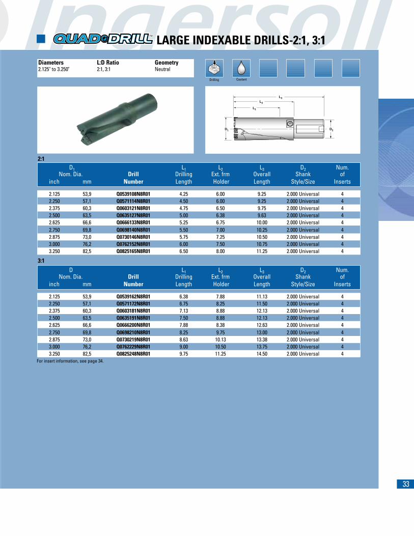
D1 L1 L2 L3 D2 Num.Nom. Dia. Drill Drilling Ext. frm Overall Shank of
inch mm Number Length Holder Length Style/Size Inserts
2.125 53,9 Q0539108N8R01 4.25 6.00 9.25 2.000 Universal 42.250 57,1 Q0571114N8R01 4.50 6.00 9.25 2.000 Universal 42.375 60,3 Q0603121N8R01 4.75 6.50 9.75 2.000 Universal 42.500 63,5 Q0635127N8R01 5.00 6.38 9.63 2.000 Universal 42.625 66,6 Q0666133N8R01 5.25 6.75 10.00 2.000 Universal 42.750 69,8 Q0698140N8R01 5.50 7.00 10.25 2.000 Universal 42.875 73,0 Q0730146N8R01 5.75 7.25 10.50 2.000 Universal 43.000 76,2 Q0762152N8R01 6.00 7.50 10.75 2.000 Universal 43.250 82,5 Q0825165N8R01 6.50 8.00 11.25 2.000 Universal 4
D L1 L2 L3 D2 Num.Nom. Dia. Drill Drilling Ext. frm Overall Shank of
inch mm Number Length Holder Length Style/Size Inserts
2.125 53,9 Q0539162N8R01 6.38 7.88 11.13 2.000 Universal 42.250 57,1 Q0571172N8R01 6.75 8.25 11.50 2.000 Universal 42.375 60,3 Q0603181N8R01 7.13 8.88 12.13 2.000 Universal 42.500 63,5 Q0635191N8R01 7.50 8.88 12.13 2.000 Universal 42.625 66,6 Q0666200N8R01 7.88 8.38 12.63 2.000 Universal 42.750 69,8 Q0698210N8R01 8.25 9.75 13.00 2.000 Universal 42.875 73,0 Q0730219N8R01 8.63 10.13 13.38 2.000 Universal 43.000 76,2 Q0762229N8R01 9.00 10.50 13.75 2.000 Universal 43.250 82,5 Q0825248N8R01 9.75 11.25 14.50 2.000 Universal 4
Drilling Coolant
� LARGE INDEXABLE DRILLS-2:1, 3:1
Diameters L:D Ratio Geometry2.125" to 3.250" 2:1, 3:1 Neutral
2:1
3:1
D1 D2
L1
L2
L3
For insert information, see page 34.
34
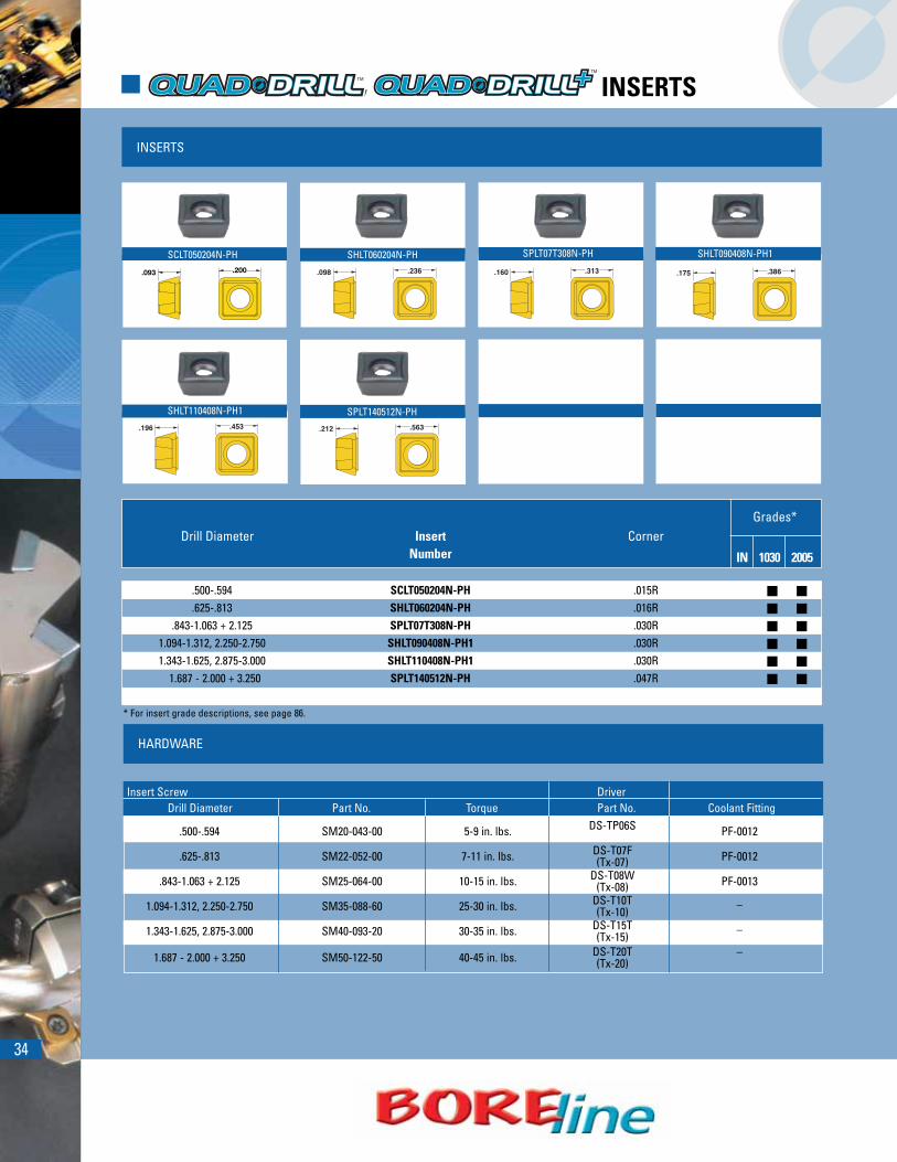
INSERTS
SHLT110408N-PH1
HARDWARE
Drill Diameter Insert CornerNumber IN 1030 2005
.500-.594 SCLT050204N-PH .015R
.625-.813 SHLT060204N-PH .016R.843-1.063 + 2.125 SPLT07T308N-PH .030R
1.094-1.312, 2.250-2.750 SHLT090408N-PH1 .030R1.343-1.625, 2.875-3.000 SHLT110408N-PH1 .030R
1.687 - 2.000 + 3.250 SPLT140512N-PH .047R
* For insert grade descriptions, see page 86.
Insert Screw DriverDrill Diameter Part No. Torque Part No. Coolant Fitting
.500-.594 SM20-043-00 5-9 in. lbs. DS-TP06S PF-0012
.625-.813 SM22-052-00 7-11 in. lbs. DS-T07F PF-0012(Tx-07)
.843-1.063 + 2.125 SM25-064-00 10-15 in. lbs. DS-T08W PF-0013(Tx-08)
1.094-1.312, 2.250-2.750 SM35-088-60 25-30 in. lbs. DS-T10T _(Tx-10)
1.343-1.625, 2.875-3.000 SM40-093-20 30-35 in. lbs. DS-T15T _(Tx-15)
1.687 - 2.000 + 3.250 SM50-122-50 40-45 in. lbs. DS-T20T –(Tx-20)
Grades*
SCLT050204N-PH SHLT060204N-PH SPLT07T308N-PH SHLT090408N-PH1
SPLT140512N-PH
� , INSERTS
� �
� �
� �
� �
� �
� �

35
D1D3 D2
L1L2
� ECCENTRIC ADJUSTMENT BUSHINGS- BU SERIES
BushingNumber D1 D2 D3 L1 L2
BU16-16 1.00 1.25 1.75 2.00 0.38BU24-44 1.25 1.50 2.00 2.10 0.38BU32-02 1.50 2.00 2.50 2.44 0.38
For technical information, see page 108.
36
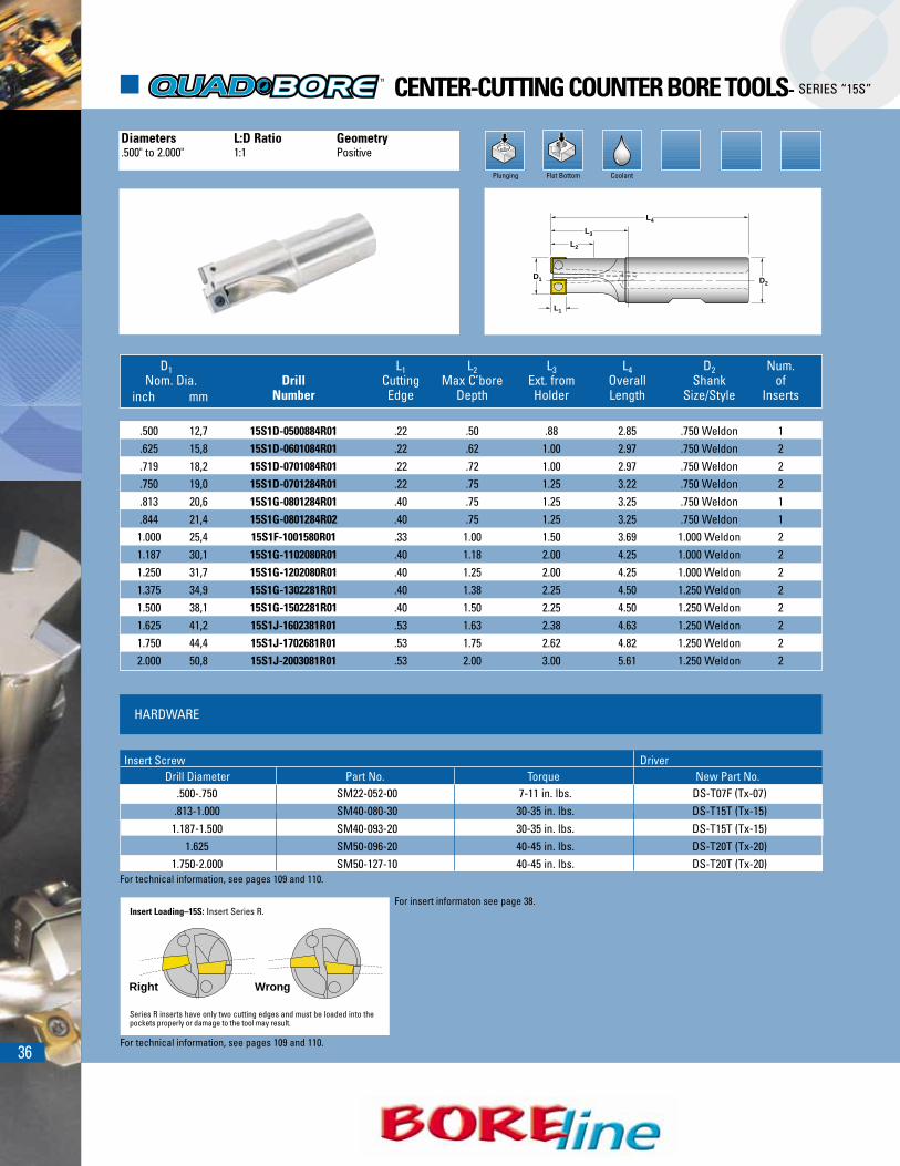
� CENTER-CUTTING COUNTER BORE TOOLS- SERIES “15S”
HARDWARE
.500-.750 SM22-052-00 7-11 in. lbs. DS-T07F (Tx-07).813-1.000 SM40-080-30 30-35 in. lbs. DS-T15T (Tx-15)1.187-1.500 SM40-093-20 30-35 in. lbs. DS-T15T (Tx-15)
1.625 SM50-096-20 40-45 in. lbs. DS-T20T (Tx-20)1.750-2.000 SM50-127-10 40-45 in. lbs. DS-T20T (Tx-20)
Insert Screw DriverDrill Diameter Part No. Torque New Part No.
D1
L1
L2
L3
L4
D2
Insert Loading–15S: Insert Series R.
Right Wrong
Series R inserts have only two cutting edges and must be loaded into thepockets properly or damage to the tool may result.
Plunging CoolantFlat Bottom
Diameters L:D Ratio Geometry.500" to 2.000" 1:1 Positive
D1 L1 L2 L3 L4 D2 Num.Nom. Dia. Drill Cutting Max C’bore Ext. from Overall Shank of
inch mm Number Edge Depth Holder Length Size/Style Inserts
.500 12,7 15S1D-0500884R01 .22 .50 .88 2.85 .750 Weldon 1
.625 15,8 15S1D-0601084R01 .22 .62 1.00 2.97 .750 Weldon 2
.719 18,2 15S1D-0701084R01 .22 .72 1.00 2.97 .750 Weldon 2
.750 19,0 15S1D-0701284R01 .22 .75 1.25 3.22 .750 Weldon 2
.813 20,6 15S1G-0801284R01 .40 .75 1.25 3.25 .750 Weldon 1
.844 21,4 15S1G-0801284R02 .40 .75 1.25 3.25 .750 Weldon 11.000 25,4 15S1F-1001580R01 .33 1.00 1.50 3.69 1.000 Weldon 21.187 30,1 15S1G-1102080R01 .40 1.18 2.00 4.25 1.000 Weldon 21.250 31,7 15S1G-1202080R01 .40 1.25 2.00 4.25 1.000 Weldon 21.375 34,9 15S1G-1302281R01 .40 1.38 2.25 4.50 1.250 Weldon 21.500 38,1 15S1G-1502281R01 .40 1.50 2.25 4.50 1.250 Weldon 21.625 41,2 15S1J-1602381R01 .53 1.63 2.38 4.63 1.250 Weldon 21.750 44,4 15S1J-1702681R01 .53 1.75 2.62 4.82 1.250 Weldon 22.000 50,8 15S1J-2003081R01 .53 2.00 3.00 5.61 1.250 Weldon 2
For technical information, see pages 109 and 110.
For insert informaton see page 38.
For technical information, see pages 109 and 110.
37
*Modified Weldon shank for more extension.
Insert Loading–15C: Insert Series R.
Right Wrong
Series R inserts have only two cutting edges and must be loaded into thepockets properly or damage to the tool may result.
Plunging Flat Bottom
Diameters L:D Ratio Geometry.438" to 2.000" 1:1 Positive
L4
L3
L2
D1
L1
D2
D1 L1 L2 L3 L4 D2 NumberNom. Dia. Drill Cutting Max C’bore Ext. from Overall Shank of
inch mm Number Edge Depth Holder Length Size/Style Inserts
.438 11,1 15C1D-0400884R01 .22 .44 .88 2.85 .750 Weldon 1 1/4 .150
.531 13,4 15C1D-0500884R01 .22 .53 .88 2.85 .750 Weldon 1 5/16 .230
.625 15,8 15C1D-0601084R01 .22 .62 1.00 2.97 .750 Weldon 2 3/8 .320
.719 18,2 15C1D-0701084R01 .22 .72 1.00 2.97 .750 Weldon 2 7/16 .420
.812 20,6 15C1E-0801284R01 .28 .81 1.25 3.25 .750 Weldon 2 1/2 .2501.000 25,4 15C1G-1001580R01 .40 1.00 1.50 3.75 1.000 Weldon 2 5/8 .2501.187 30,1 15C1G-1102080R01 .40 1.18 2.00 4.25 1.000 Weldon 2 3/4 .4371.250 31,7 15C1G-1202080R01 .40 1.25 2.00 4.25 1.000 Weldon 2 - .5001.375 34,9 15C1G-1302281R01 .40 1.38 2.25 4.50 1.250 Weldon 3 - .6251.500 38,1 15C1G-1502281R01 .40 1.50 2.25 4.50 1.250 Weldon 3 - .7501.500 38,1 15C1G-1503781R01 .40 1.00 3.75 6.00 1.250 Weldon* 3 - .7501.750 44,4 15C1J-1702681R01 .53 1.75 2.62 4.82 1.250 Weldon 2 - .8802.000 50,8 15C1J-2003081R01 .53 2.00 3.00 5.25 1.250 Weldon 4 - 1.120
Min. Cored Hole Dia.
Socket Head Min. CoredCap Screw Hole Dia.
� INDEXABLE COUNTER BORING TOOLS- SERIES “15C”
For technical information, see pages 109 and 110.
For technical information, see pages 109 and 110.
For insert informaton see page 38.
HARDWARE
0.438 SM22-037-00 7-11 in. lbs. DS-T07F (Tx-07).531-.719 SM22-052-30 7-11 in. lbs. DS-T07F (Tx-07)
0.812 SM30-065-20 13-18 in. lbs. DS-T09W (Tx-09)1.000-1.500 SM40-093-20 30-35 in. lbs. DS-T15T (Tx-15)
1.750 SM50-127-10 40-45 in. lbs. DS-T20T (Tx-20)2.000 SM50-096-20 40-45 in. lbs. DS-T20T (Tx-20)
Insert Screw DriverDrill Diameter Part No. Torque New Part No.
38
.156 .313
SDLT07T308N-PH.090 .243
SPLT060204R-DM04
.156 .313
SDLT07T308N-PS
.104 .243
SPLT060204R
.181 .372
SHLT090408N-FS
.181 .372
SHLT090408N-PH
.181 .372
SHLT090416N-FS
*For Insert Descriptions, see page 86.
INSERTS
.229 .560
SHLT140508N-FS
.181 .435
SHLT110408N-FS
.181 .434
SHLT110408TN-HR
.181 .435
SHLT110416N-FS.181 .435
SHLT110408N-PH
.229 .560
SHLT140516N-FS.229 .560
SHLT140508TN-HR
.229 .560
SHLT140508N-PH
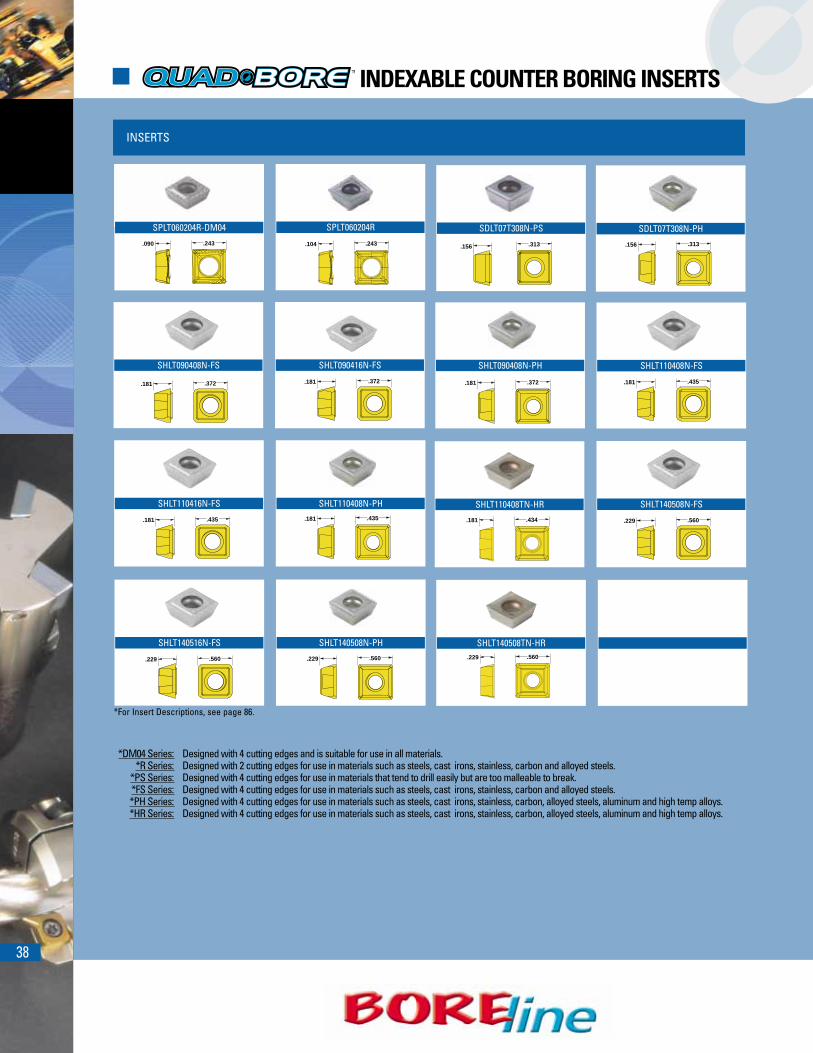
� INDEXABLE COUNTER BORING INSERTS
*DM04 Series: Designed with 4 cutting edges and is suitable for use in all materials.*R Series: Designed with 2 cutting edges for use in materials such as steels, cast irons, stainless, carbon and alloyed steels.
*PS Series: Designed with 4 cutting edges for use in materials that tend to drill easily but are too malleable to break.*FS Series: Designed with 4 cutting edges for use in materials such as steels, cast irons, stainless, carbon and alloyed steels.*PH Series: Designed with 4 cutting edges for use in materials such as steels, cast irons, stainless, carbon, alloyed steels, aluminum and high temp alloys.*HR Series: Designed with 4 cutting edges for use in materials such as steels, cast irons, stainless, carbon, alloyed steels, aluminum and high temp alloys.

39
15CCounterbore Diameter Insert Corner
inch mm Number IN 30M 40P 1030 1040 2005 6515 6530
.438 to .719 11,1 to 18,2 SPLT060204R-DM04 .016R �
.438 to .719 11,1 to 18,2 SPLT060204R .016R � � �
.812 20,6 SDLT07T308N-PS .030R �
.812 20,6 SDLT07T308N-PH .030R �
1.000 to 1.500 25,4 to 38,1 SHLT110408N-FS .030R � � �
1.000 to 1.500 25,4 to 38,1 SHLT110416N-FS .060R �
1.000 to 1.500 25,4 to 38,1 SHLT110408TN-PH .030R �
1.000 to 1.500 25,4 to 38,1 SHLT110408N-HR .030R � � � � �
1.750 to 2.000 44,4 to 50,8 SHLT140508N-FS .030R � � �
1.750 to 2.000 44,4 to 50,8 SHLT140516N-FS .060R � �
1.750 to 2.000 44,4 to 50,8 SHLT140508N-PH .030R �
1.750 to 2.000 44,4 to 50,8 SHLT140508TN-HR .030R � � � � �
Grade*
Insert CornerNumber IN 30M 40P 1030 1040 2005 6515 6530
.500 to .750 11,1 to 19,0 SPLT060204R-DM04 .016R �
.500 to .750 11,1 to 19,0 SPLT060204R .016R � � �
.500 to .750 11,1 to 19,0 SPLT060204-DM .016R
.813 to 1.500 20,7 to 38,1 SHLT110408N-FS .030R � � �
.813 to 1.500 20,7 to 38,1 SHLT110416N-FS .060R � �
.813 to 1.500 20,7 to 38,1 SHLT110408N-PH .030R �
.813 to 1.500 20,7 to 38,1 SHLT110408N-HR .030R � � �
1.000 25,4 SHLT090408N-FS .030R � � �
1.000 25,4 SHLT090416N-FS .060R � �
1.000 25,4 SHLT090408N-PH .030R �
1.625 to 2.000 41,2 to 50,8 SHLT140508N-FS .030R � � �
1.625 to 2.000 41,2 to 50,8 SHLT140516N-FS .060R � �
1.625 to 2.000 41,2 to 50,8 SHLT140508N-PH .030R �
1.625 to 2.000 41,2 to 50,8 SHLT140508N-HR .030R � � � � �* For insert grade descriptions, see page 86.
* For insert grade descriptions, see page 86.
15SCenter Cutting
Counterbore Diameter
Grade*
Series 15C1G, 15C1J, 15S1G and 15S1TJcan use optional insert SeriesSHLT110408TN-HR & SHLT140508TN-HR.These inserts include a chipbreaker de-signed to enhance chip formation whenend milling. Do not use SeriesSHLT110408TN-HR or SHLT140508TN-HRinserts for counterboring applications.
Optional InsertsInsert Series SHLT110408TN-HR & SHLT140508TN-HR for End Milling.
inch mm
40
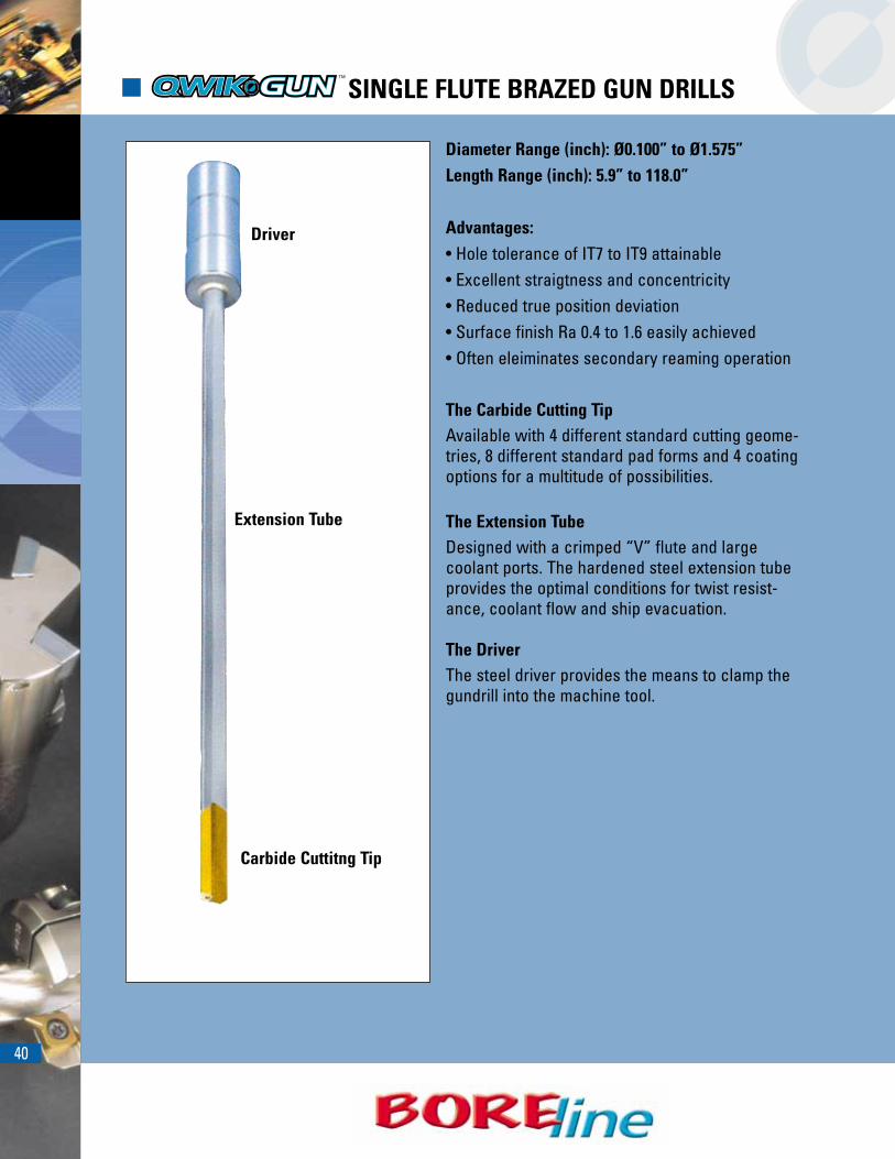
� SINGLE FLUTE BRAZED GUN DRILLS
Diameter Range (inch): Ø0.100” to Ø1.575”Length Range (inch): 5.9” to 118.0”
Advantages:• Hole tolerance of IT7 to IT9 attainable• Excellent straigtness and concentricity• Reduced true position deviation• Surface finish Ra 0.4 to 1.6 easily achieved• Often eleiminates secondary reaming operation
The Carbide Cutting TipAvailable with 4 different standard cutting geome-tries, 8 different standard pad forms and 4 coatingoptions for a multitude of possibilities.
The Extension Tube Designed with a crimped “V” flute and largecoolant ports. The hardened steel extension tubeprovides the optimal conditions for twist resist-ance, coolant flow and ship evacuation.
The DriverThe steel driver provides the means to clamp thegundrill into the machine tool.
Extension Tube
Carbide Cuttitng Tip
Driver

41
� SOLID CARBIDE GUNDRILLS
Made with an integral cutting tip and extensiontube with either a steel or carbide driver. Thesolid carbide gun drill is designed for use in con-ventional machining centers and lathes. Thesedrills provide superior rigidity with optimumcoolant flow. As a result, speeds and feeds up to100% faster may be obtained.
Diameter Range (inch): Ø.055” to Ø.630”Length Range (inch): 40 x Drill Diameter up to7.874” flute length

42
� STANDARD GUN DRILL SHARPENING ANGLES
Depending on the required tolerance,cutting performance and desired chipshape, the following standard sharpeningangles are recommended
Standard sharpening for diameters greater than .157”
Standard sharpening for diameters less than .157”
Optional sharpening for materials where it is difficult tobreak a chip.
D
0.25xD
30˚
15˚
30˚
30˚
40˚35˚
D
30˚
12˚
20˚
20˚
30˚25˚
.0118
-.019
7
12˚
0.25xD
D/4±0,05
30˚
40˚
35˚25˚
30˚38˚
15˚
Standard Gundrill Carbide Length
Diameter Range Head Length.098” - .149” .787”.150” - .159” .906”.160” - .199” .094”.200” - .258” 1.181”.259” - .435” 1.378”.436” - .722” 1.575”.723” - .841” 1.772”.842” - .919” 1.970”.920” - .1.037” 2.165”.1.038” - 1.260” 2.560”Regrindable Length = Length-Dia.

43
� STANDARD GUN DRILL PAD FORMS
Drilling capacity and hole finish are dependent on the geometrical shape of the drill head. Both the padform and the sharpening must be matched to the workpiece material. The pad form is determined whenthe tool is manufactured. Regrinding may change the cutting geometry, but the pad form will remain thesame.
Applications:For all material groupsWorks well in materials that tendto shrinkMaintains precision bore toleranceand straightness
Applications:For cast iron & aluminum alloysMaintains high precision holetolerancesExcellent surface finish
Applications:For cast iron & aluminum alloys(coated)Drilling through cross holes andangled entry and exitsLarge gap between pads ensuresgood lubrication
Applications:General purpose for all materialsCommonly used in crankshaft andother forged materialsPrecise straightness control
Applications:For cast iron only ( with coating)Works very well in grey cast iron
Applications:With larger back taper for use inmaterials that tend to shrink.(Some alloys and stainless)Drilling through cross holes andangled entry and exitNot recommended for precisestraightness control
Applications:For aluminum and brass when bestsurface finish is requiredCan be used in cross hole andinterrupted cut applications
Applications:For all non-ferrous materialsFor cast iron greater than .200” holediameterCan be used in wood & plastic witha larger back taper
All cross section profileparameters such as: P, Laand � must be preciselymatched to the workpiecematerial properties.
Universal G Form Standard A Form
Standard C FormStandard B Form Standard D Form
Standard H FormStandard E Form Standard I Form
44
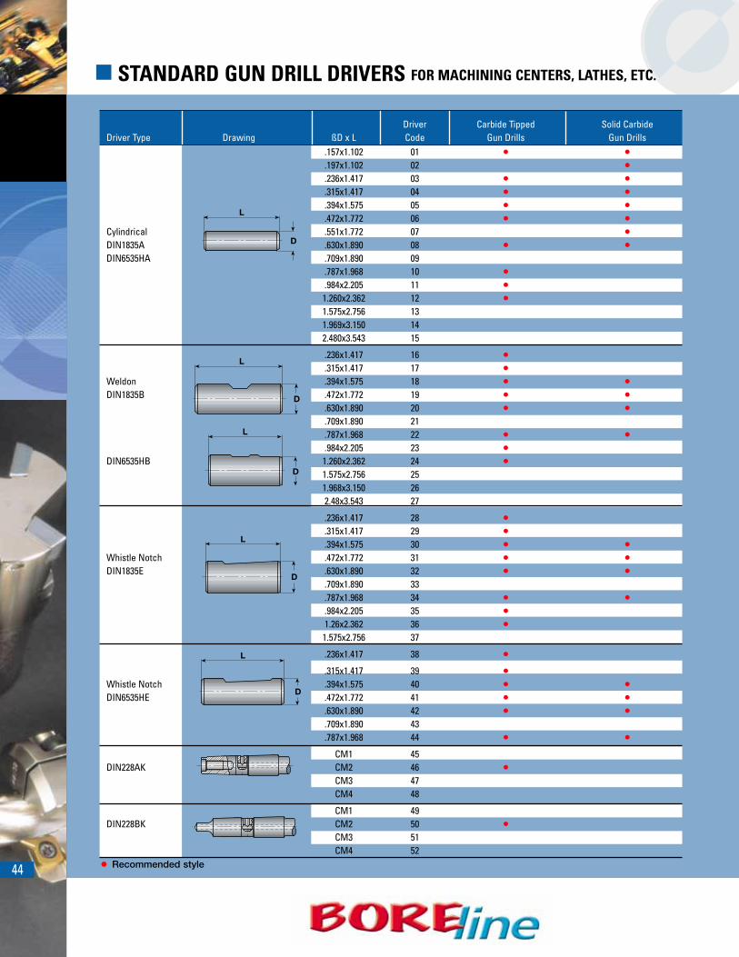
� STANDARD GUN DRILL DRIVERS FOR MACHINING CENTERS, LATHES, ETC.
L
D
L
D
L
D
L
D
L
D
• Recommended style
Driver Carbide Tipped Solid CarbideDriver Type Drawing ßD x L Code Gun Drills Gun Drills
.157x1.102 01 • •
.197x1.102 02 •
.236x1.417 03 • •
.315x1.417 04 • •
.394x1.575 05 • •
.472x1.772 06 • •Cylindrical .551x1.772 07 •DIN1835A .630x1.890 08 • •DIN6535HA .709x1.890 09
.787x1.968 10 •
.984x2.205 11 •1.260x2.362 12 •1.575x2.756 131.969x3.150 142.480x3.543 15
.236x1.417 16 •
.315x1.417 17 •Weldon .394x1.575 18 • •DIN1835B .472x1.772 19 • •
.630x1.890 20 • •
.709x1.890 21
.787x1.968 22 • •
.984x2.205 23 •DIN6535HB 1.260x2.362 24 •
1.575x2.756 251.968x3.150 262.48x3.543 27
.236x1.417 28 •
.315x1.417 29 •
.394x1.575 30 • •Whistle Notch .472x1.772 31 • •DIN1835E .630x1.890 32 • •
.709x1.890 33
.787x1.968 34 • •
.984x2.205 35 •1.26x2.362 36 •1.575x2.756 37
.236x1.417 38 •
.315x1.417 39 •Whistle Notch .394x1.575 40 • •DIN6535HE .472x1.772 41 • •
.630x1.890 42 • •
.709x1.890 43
.787x1.968 44 • •CM1 45
DIN228AK CM2 46 •CM3 47CM4 48
CM1 49DIN228BK CM2 50 •
CM3 51CM4 52

45
� STANDARD GUN DRILL DRIVERS FOR GUN DRILL MACHINES
• Recommended style
L
D
L
Tr D
L
D
L
D
L
D
LMD
LM
D
L
D
L
D
Driver Carbide Tipped Solid CarbideDriver Type Drawing D x L Code Gun Drills Gun Drills
.236x1.181 53 •
.394x1.575 54 • •
.630x1.772 55 •Central Clamping .750x2.748 56 •Surface 15° .984x2.756 57 •
1.00x2.748 58 •1.25x2.748 59 •1.50x2.748 60
Frontal Clamping
.630x1.968 61 •Surface 15°
.394x1.968 M6X0.5 62 •
.394x2.362 M6X0.5 63 •.500x1.968 M6x0.5 64 •
Cylindrical .630x3.150 M10X1 65 • •with Thread .984x3.937 M16x1.5 66 •
1.417x4.724 M24x1.5 67.394x2.677 M6x0.5 68 •
VDI Design .630x3.543 M10x1 69 • •.984x4.409 M16x1.5 70 •1.417x5.315 M24x1.5 71
Central Clamping .984x2.756 72 •Hexagonal 1.26x2.756 73 •
.500x1.500 74 • •Central Clamping .630x2.756 75Tapered .750x2.748 76 •
.787x2.756 77
.500x1.500 78 •
.750x2.748 79 •1.00x2.748 80 •
Frontal Clamping 1.00x3.937 81 •Surface 2° 1.25x2.748 82 •
1.25x3.937 83 •1.50x2.748 841.50x3.937 85
.630x4.409 Tr 16x1.5 86 •Trapezoidal .787x4.960 Tr 20x2 87 •Thread 1.102x4.960 Tr 28x2 88 •
1.417x6.378 Tr 36x2 89.630x1.575 90 •
Spraymist Driver .984x1.968 91 •1.378x2.362 92 •

� SOLID CARBIDE GUN DRILLS
46
� BRAZED GUN DRILLS
All Ingersoll brazed gun drills are made toorder. Standard gun drill components,carbide tips, extension tubes and driversare kept in stock.
STANDARD DESIGN• Standard diameters:
Ø.098” to .787” available in .004” incrementsØ.788” to 1.260” available in .039” (1mm) incrementsStandard sub-micron carbide Grade (K15)
• Standard inch sizes in stock: 1/4, 7/16, 3/8, 1/2, 9/16. 5/8, 3/4
• Standard pad form = G form (Standard inch sizes = E form)
• Standard back taper (0.07%)• Standard sharpening• Uncoated• Standard driver
SEMI-STANDARD DESIGN• Out of standard diameter range• Any other pad form from the catalog
other than G or E• Special surface finish• Any coating
SPECIAL DESIGN• Any non-catalog specification
All Ingersoll solid carbide gun drillsare made to order. Standard solid carbide gun drills and drivers are kept in stock.
STANDARD DESIGN• Standard sub-micron carbide
Grade (K15)• Standard pad form (G)• Standard back taper (0.07%)• Standard sharpening• Uncoated• Standard driver
SEMI-STANDARD DESIGN• Any other pad form from the catalog• Special surface finish• Coating
SPECIAL DESIGN• Any non-catalog specification

47
� GUN DRILL REQUEST FOR QUOTATION FORMCUSTOMERCustomer Number Company NameAddressContact Person
Pad Forms
Hole Type (Check all that apply)Blind Hole Through HoleAngled entry Angled exitDrilling from solid Core drillCross holes Other (text)
THE PIECE PARTNamePart Number
THE TOOLPart Number
THE MACHINE
Hole DiameterToleranceSurface Finish (Ra, Rz,...)Concentricity (.001”/1.0”)Straightness (.001”/1.0’)
Hole Depth
Material (Din material, spec etc.)Steel Iron Aluminum
Stainless steel Nickel OtherHardness
Long chips Short chips
ApplicationWorkpiece Stationary RotatingTool Stationary Rotating
Cutting Data Max Possible CurrentCutting speed “Vc” (SFM)Revolutions per minuteFeed “f” (in/rev)Feed “F” (in/min)
Machine Type/ModelPower [hp/Kw]Rigidity: Good Average Poor
Drill Guide Method Internal Dia. TolerancePre-Drilled pilot holeBushing
CoolantPressure “P” (psi)Flow Rate (gal/min)Neat Oil Soluable %
Additional Information
Inquiry NumberInquiry Date
Quantities Requested
Tool Type Carbide TippedUnknown Solid CarbideSingle Lipped Double LippedCustomer Drawing No.
Tool Diameter [in/mm]Tolerance h5 Other
Coating of the Carbide TipUncoated TiAINTiN AITiNTiCN UnknownTiN + TiCN Other
Carbide Tip Length OtherStandard
Overall Length [in/mm]Flute Length [in/mm]
DriverList Std catalog numberOther Length x DiameterDriver Extension L x Dia
A
B
HID
C
EG
Grind Geometry
D
30˚
12˚
20˚
20˚
30˚25˚
.0118
-.019
7
12˚
0.25xD
Std grind for diameters from .055” thru .157”—1=40 —2=30 d=D/4—1=30 —2=15 —3=35 —1=0 —2=30 b=0
Std grind for diameters from .158” thru 1.260”—1=30 —2=20 d=D/4—1=12 —2=12 —3=25 —1=25 —2=30 b=0,3/0,5
Other —1= —2= d=—1= —2= —3= —1= —2= b=

48
� DEEP DRILLING APPLICATIONS
Gun drill boring operation in blind hole whenchips and coolant are evacuated backthrough the flute.
Gun drilling operation in blind hole whenchips and coolant are evacuated backthrough the flute.
Gundrill boring operation in through holewhen chips and coolant are evacuated aheadof the drill tip.
Stepped gundrill boring operation in throughhole when chips and coolant are evacuatedahead of the drill tip.
49
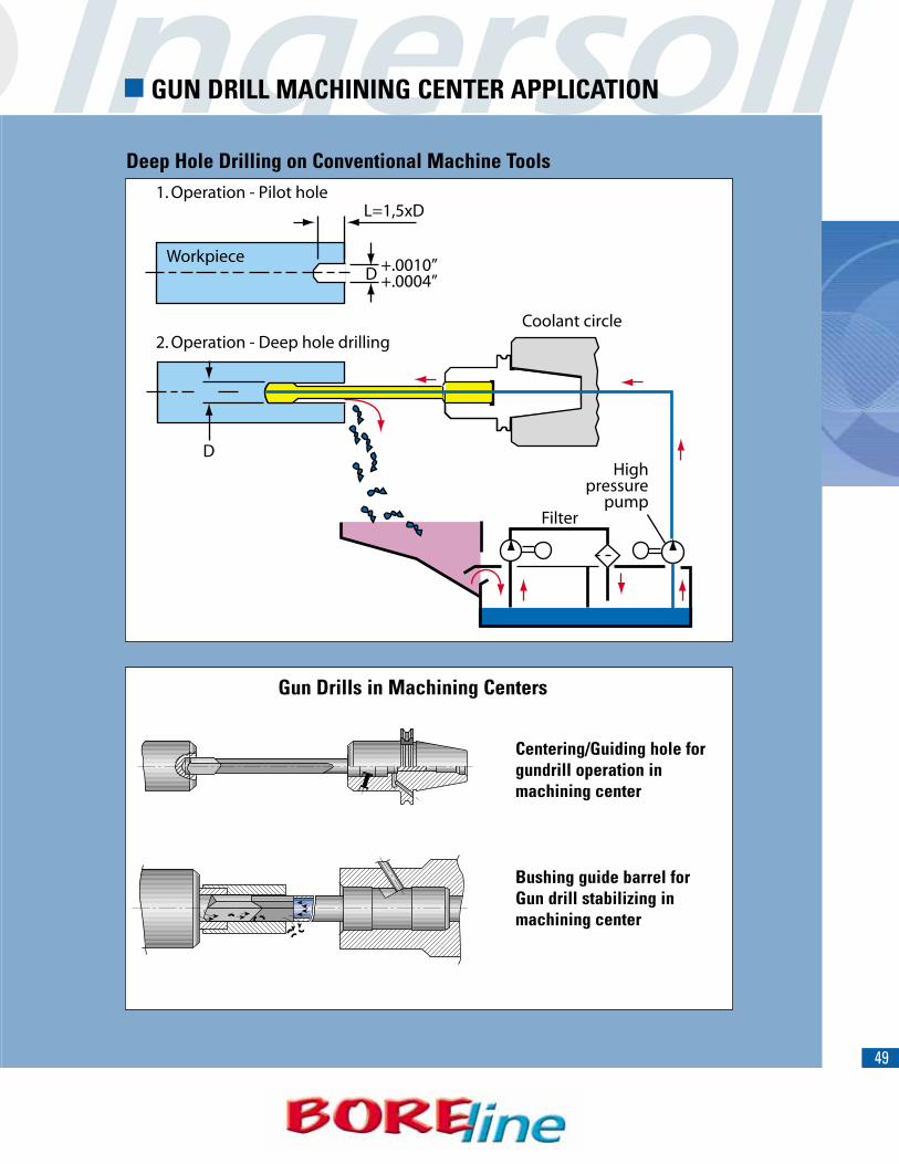
� GUN DRILL MACHINING CENTER APPLICATION
1. Operation - Pilot hole
2. Operation - Deep hole drillingCoolant circle
Highpressure
pumpFilter
D
L=1,5xD
D +.0010”+.0004”
Workpiece
Centering/Guiding hole forgundrill operation in machining center
Bushing guide barrel for Gun drill stabilizing in machining center
Gun Drills in Machining Centers
Deep Hole Drilling on Conventional Machine Tools
50
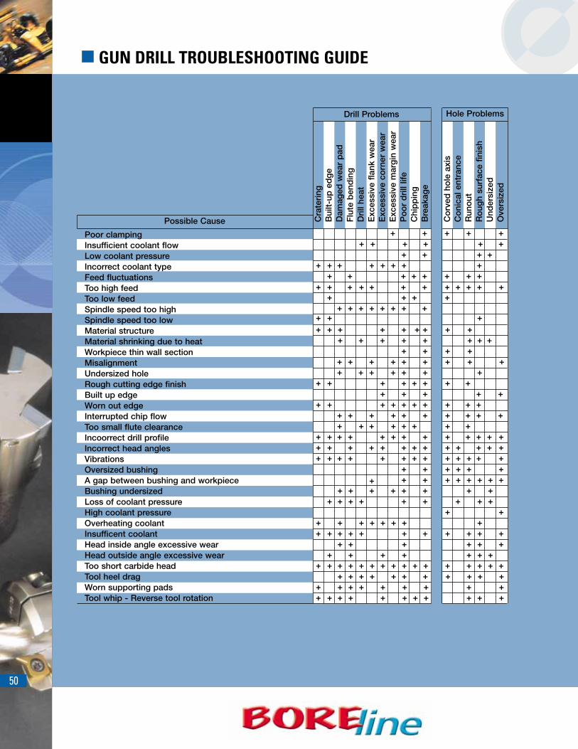
� GUN DRILL TROUBLESHOOTING GUIDE
Hole Problems
Poor clampingInsufficient coolant flowLow coolant pressureIncorrect coolant typeFeed fluctuationsToo high feedToo low feedSpindle speed too highSpindle speed too lowMaterial structureMaterial shrinking due to heatWorkpiece thin wall sectionMisalignmentUndersized holeRough cutting edge finishBuilt up edgeWorn out edgeInterrupted chip flowToo small flute clearanceIncoorrect drill profileIncorrect head anglesVibrationsOversized bushingA gap between bushing and workpieceBushing undersizedLoss of coolant pressureHigh coolant pressureOverheating coolantInsufficent coolantHead inside angle excessive wearHead outside angle excessive wearToo short carbide headTool heel dragWorn supporting padsTool whip - Reverse tool rotation
Cra
teri
ngB
uilt-
up e
dg
eD
amag
ed w
ear
pad
Flu
te b
end
ing
Dri
ll he
atE
xces
sive
fla
nk w
ear
Exc
essi
ve c
orn
er w
ear
Exc
essi
ve m
arg
in w
ear
Po
or
dri
ll lif
eC
hip
pin
gB
reak
age
Drill Problems
Co
rved
ho
le a
xis
Co
nica
l ent
ranc
eR
uno
utR
oug
h su
rfac
e fin
ish
Und
ersi
zed
Ove
rsiz
ed
+
+
++
+
+
++
+
+
+
++
+
+ ++ + + + +
+
+
+ +++
+ + ++ + ++ ++ +
++
+ + + + + + +
+
+++++
+++
++ +
+
+ + + + + + + + ++++ + + + + + +++
+ + + + + + + + + + ++ + + + + + + + + + + + + + + +
+ + ++ + ++
++
+++++
++
++ + + + + ++
++ +
+++++++++++++++++
+++++++
++
+
+
+
++++++++++
++++++++
++++
+++
+ + +++
++
++++
+++
+++
+++
++
+
+++ +
++++
+++++
+
+
+
++
+ ++
+++
+
+++
++
+++
+++
+++ +
+++
++
+
+
+
++++
+
+++
+++
+++
++
++
+ + ++ + + +
+ +
++
+
Possible Cause

51


Description Detail Page
CAT-ER Collet Chuck CAT-ER 16-20 57
CAT-ER Collet Chuck CAT-ER 25-50 58
CAT-TG Collet Chuck CAT-TG100 59
CAT- Endmill Holder CAT-EM 60
HSK-ER Collet Chuck (Metric) HSK E-ER16/ER20/ER32 63
HSK-ER Mini Collet Chuck (Metric) HSK A-ER-M 64
HSK-ER Collet Chuck (Metric) HSK A-ER 65
HSK-ER Collet Chuck (Metric) HSK A-ER 65
HSK- Endmill Holder HSK A-EM 67
54
Description Detail Page
ER Spring Collets .0004 ER-11,16,20,25-SPR / ER32,40-SPR 73
ER Spring Collets .0004 ER50-SPR / ER-EX 74
ER Spring Collets .0002 ER11,16,20-SPR-AA / ER25,32-SPR-AA 75
ER Spring Collets .0002 ER40 76
TG100 Collet + Spring Collets TG100+-SPR / SET-TG100+-SPR 77
ER Coolit - Sealed Jet Collets ER16,20,25-SEAL / ER32,40-SEAL 78
ER Coolit - Sealed Jet2 Collets ER16,20,25-SEAL / JET2 79
ER Coolit - Sealed Jet2 Spring Collets ER32,40-SEAL-JET2 80
TG100 Coolit-Sealed Spring Collets TG100-SEAL 81
ER Spring Collet Serts – 82
55
56
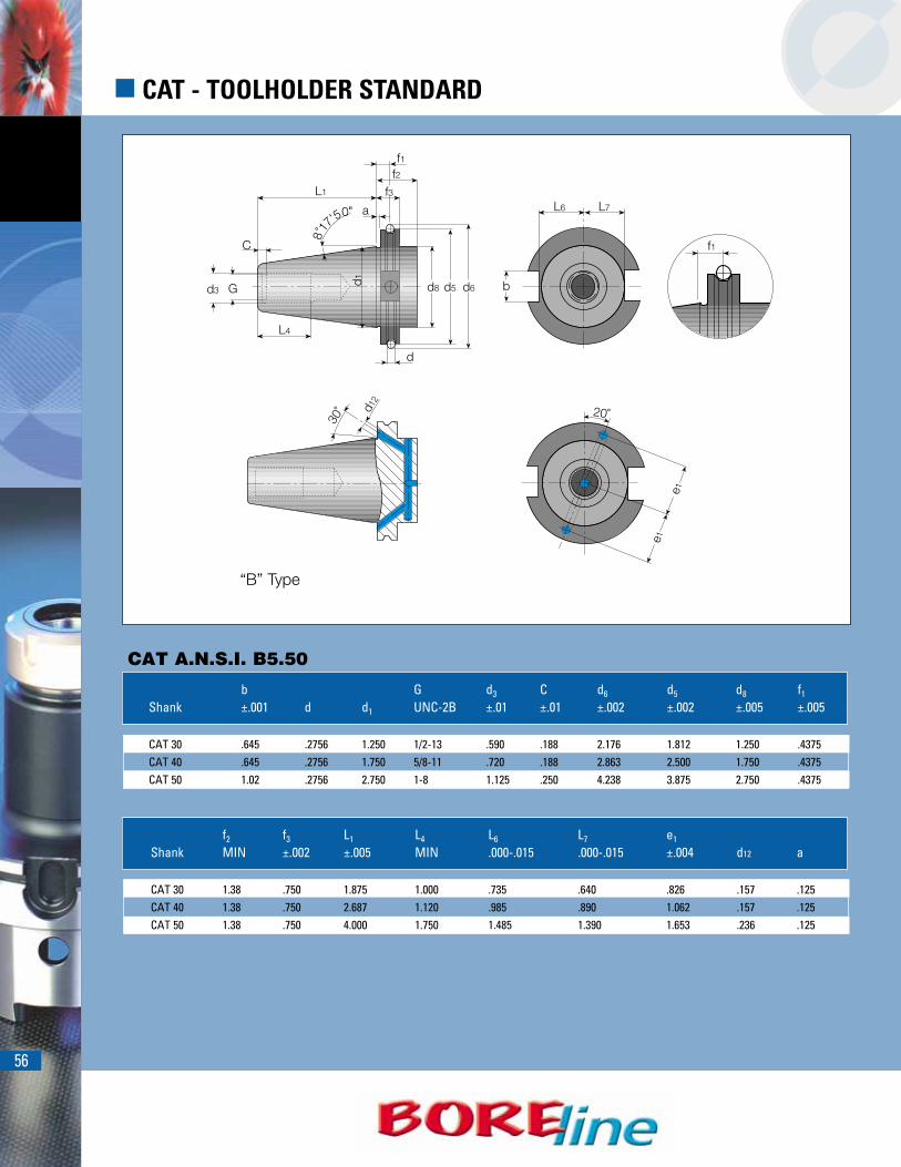
� CAT - TOOLHOLDER STANDARD
CAT A.N.S.I. B5.50
b G d3 C d6 d5 d8 f1
Shank ±.001 d d1 UNC-2B ±.01 ±.01 ±.002 ±.002 ±.005 ±.005
CAT 30 .645 .2756 1.250 1/2-13 .590 .188 2.176 1.812 1.250 .4375CAT 40 .645 .2756 1.750 5/8-11 .720 .188 2.863 2.500 1.750 .4375CAT 50 1.02 .2756 2.750 1-8 1.125 .250 4.238 3.875 2.750 .4375
f2 f3 L1 L4 L6 L7 e1
Shank MIN ±.002 ±.005 MIN .000-.015 .000-.015 ±.004 d12 a
CAT 30 1.38 .750 1.875 1.000 .735 .640 .826 .157 .125CAT 40 1.38 .750 2.687 1.120 .985 .890 1.062 .157 .125CAT 50 1.38 .750 4.000 1.750 1.485 1.390 1.653 .236 .125
“B” Type

57
* Balanced to G6.3 12000 RPM.
CAT A.N.S.I. B5.50 DIN 6499
Designation Range L L1 L2 D D1 J G
CAT30 ER16X2.750 * .022-.396 2.750 2.000 1.370 1.102 1.248 M10 1/2-13CAT40 ER16X2.750 .022-.396 2.750 2.000 1.370 1.102 1.752 M12 5/8-11CAT40 ER16X3.937 .022-.396 3.937 3.187 2.560 1.102 1.752 M12 5/8-11CAT40 ER16X5.906 .022-.396 5.906 5.156 3.350 1.102 1.752 M12 5/8-11CAT40 ER20X3.937 .041-.514 3.937 3.187 2.560 1.339 1.752 M12 5/8-11CAT40 ER20X4.000 .041-.514 4.000 3.250 2.620 1.339 1.752 M12 5/8-11CAT40 ER20X5.906 .041-.514 5.906 5.156 3.780 1.339 1.752 M12 5/8-11CAT50 ER16X3.937 * .022-.396 3.937 3.187 2.560 1.102 2.752 M12 1-8CAT50 ER16X5.906 * .022-.396 5.906 5.156 3.490 1.102 2.752 M12 1-8CAT50 ER16X8.000 * .022-.396 8.000 7.250 2.980 1.102 2.752 M12 1-8CAT50 ER20X3.937 * .041-.514 3.937 3.187 2.560 1.349 2.752 M16 1-8CAT50 ER20X5.906 * .041-.514 5.906 5.156 4.530 1.349 2.752 M16 1-8CAT50 ER20X8.000 * .041-.514 8.000 7.250 4.620 1.339 2.752 M16 1-8
Add B suffix for coolant through flange. Ra 4µin58-60 HRcAT3 Taper➚ A .00012A
� CAT - ER COLLET CHUCK CAT-ER 16-20
G
L1
L
L2
D1
D
J

58
� CAT - ER COLLET CHUCK CAT-ER 25-50
CAT A.N.S.I. B5.50 DIN 6499
Add B suffix for coolant through flange. Ra 4µin58-60 HRcAT3 Taper➚ A .00012A
Through-Flange coolant available.
* Balance to G6.3 12000 RPM.
Designation Range L L1 L2 D D1 J G
CAT30 ER32X3.268 * .080-.789 3.268 2.518 1.890 1.968 1.248 M18X1.5 1/2-13CAT40 ER25X2.562 .041-.632 2.562 1.812 1.180 1.654 1.752 M16 5/8-11CAT40 ER25X4.000 .041-.632 4.000 3.250 2.620 1.654 1.752 M16 5/8-11CAT40 ER25X6.000 .041-.632 6.000 5.250 4.620 1.654 1.752 M16 5/8-11CAT40 ER32X2.562 .080-.789 2.562 1.812 - 1.968 1.752 M22X1.5 5/8-11CAT40 ER32X 4.000 .080-.789 4.000 3.250 - 1.968 1.752 M22X1.5 5/8-11CAT40 ER32X 6.000 .080-.789 6.000 5.250 - 1.968 1.752 M22X1.5 5/8-11CAT40 ER40X3.359 .120-1.025 3.359 2.609 - 2.480 1.752 M28X1.5 5/8-11CAT40 ER40X 4.000 .120-1.025 4.000 3.250 - 2.480 1.752 M28X1.8 5/8-11CAT50 ER25X4.000 * .041-.632 4.000 3.250 2.580 1.654 2.752 M16 1-8CAT50 ER25X6.000 * .041-.632 6.000 5.250 4.620 1.654 2.752 M16 1-8CAT50 ER25X8.000 * .041-.632 8.000 7.250 6.580 1.654 2.752 M16 1-8CAT50 ER32X4.000 * .080-.789 4.000 3.250 2.540 1.968 2.752 M22X1.5 1-8CAT50 ER32 X6.000 * .080-.789 6.000 5.250 4.580 1.968 2.752 M22X1.5 1-8CAT50 ER32 X8.000 * .080-.789 8.000 7.250 6.580 1.968 2.752 M22X1.5 1-8CAT50 ER40 X4.000 * .120-1.025 4.000 3.250 2.620 2.480 2.752 M28X1.5 1-8CAT50 ER40 X6.000( * .120-1.025 6.000 5.250 4.620 2.480 2.752 M28X1.5 1-8CAT50 ER40 X8.000 * .120-1.025 8.000 7.250 6.580 2.480 2.752 M28X1.5 1-8CAT50 ER50 X4.000 * .396-1.338 4.000 3.250 - 3.070 2.752 M36X1.5 1-8CAT50 ER50 X6.000 * .396-1.338 6.000 5.250 - 3.070 2.752 M36X1.5 1-8
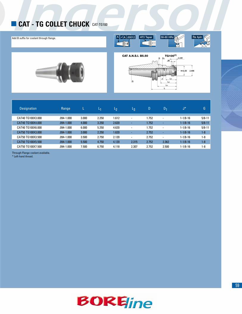
59
CAT A.N.S.I. B5.50 TG100(1)
Add B suffix for coolant through flange. Ra 4µin58-60 HRcAT3 Taper➚ A .00012A
� CAT - TG COLLET CHUCK CAT-TG100
G
H=2.25 2.406
L1
L
L2
L3
D1D 1.142.30
J
Through-Flange coolant available.* Left-hand thread.
Designation Range L L1 L2 L3 D D1 J* G
CAT40 TG100X3.000 .094-1.000 3.000 2.250 1.612 - 1.752 - 1-1/8-16 5/8-11CAT40 TG100X4.000 .094-1.000 4.000 3.250 2.620 - 1.752 - 1-1/8-16 5/8-11CAT40 TG100X6.000 .094-1.000 6.000 5.250 4.620 - 1.752 - 1-1/8-16 5/8-11CAT50 TG100X3.000 .094-1.000 3.000 2.250 1.620 - 2.752 - 1-1/8-16 1-8CAT50 TG100X3.500 .094-1.000 3.500 2.750 2.120 - 2.752 - 1-1/8-16 1-8CAT50 TG100X5.500 .094-1.000 5.500 4.750 4.120 2.315 2.752 2.362 1-1/8-16 1-8CAT50 TG100X7.500 .094-1.000 7.500 6.750 4.118 2.307 2.752 2.500 1-1/8-16 1-8

60
� CAT - ENDMILL HOLDER CAT-EM
CAT A.N.S.I. B5.50 WELDON
Add B suffix for coolant through flange. Ra 4µin58-60 HRcAT3 Taper➚ A .00020A
G
L
L1
L2
dD 1.752 1.752
L2
Dd
SHANK DIA.7/8+”
Through-Flange coolant available.
Designation d L L1 L2 D G
CAT40 EM 3/16X2.500 .187 2.500 1.750 1.121 .866 5/8-11CAT40 EM 1/4X2.500 .250 2.500 1.750 1.121 1.000 5/8-11CAT40 EM 3/8X2.500 .375 2.500 1.750 1.121 1.248 5/8-11CAT40 EM 1/2X2.625 .500 2.625 1.875 - - 5/8-11CAT40 EM 5/8X3.750 .625 3.750 3.000 - - 5/8-11CAT40 EM 3/4X3.750 .750 3.750 3.000 - - 5/8-11CAT40 EM 7/8X4.000 .875 4.000 3.250 2.620 2.047 5/8-11CAT40 EM 1X4.000 1.000 4.000 3.250 2.620 2.559 5/8-11CAT40 EM 1-1/4X4.250 1.250 4.250 3.500 2.870 2.752 5/8-11CAT40 EM 1-1/2X4.625 1.500 4.625 3.875 3.245 3.150 5/8-11
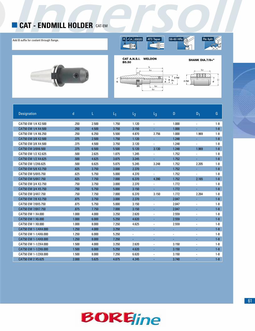
61
Add B suffix for coolant through flange.
CAT A.N.S.I. B5.50
WELDON
Ra 4µin58-60 HRcAT3 Taper➚ A .00020A
� CAT - ENDMILL HOLDER CAT-EM
SHANK DIA.7/8+”
G
L
L1
L3
L2
2.752D1D
d
L2
Dd2.752
Designation d L L1 L2 L3 D D1 G
CAT50 EM 1/4 X2.500 .250 2.500 1.750 1.120 - 1.000 - 1-8CAT50 EM 1/4 X4.500 .250 4.500 3.750 3.150 - 1.000 - 1-8CAT50 EM 1/4 X6.250 .250 6.250 5.500 4.870 2.756 1.000 1.969 1-8CAT50 EM 3/8 X2.500 .375 2.500 1.750 1.120 - 1.248 - 1-8CAT50 EM 3/8 X4.500 .375 4.500 3.750 3.120 - 1.248 - 1-8CAT50 EM 3/8X6.500 .375 6.500 5.500 5.120 3.130 1.248 1.969 1-8CAT50 EM 1/2 X2.625 .500 2.625 1.875 1.245 - 1.752 - 1-8CAT50 EM 1/2 X4.625 .500 4.625 3.875 3.245 - 1.752 - 1-8CAT50 EM 1/2X6.625 .500 6.625 5.875 5.245 3.248 1.752 2.205 1-8CAT50 EM 5/8 X3.750 .625 3.750 3.000 2.370 - 1.752 - 1-8CAT50 EM 5/8X5.750 .625 5.750 5.000 4.370 - 1.752 - 1-8CAT50 EM 5/8X7.750 .625 7.750 7.000 6.370 4.390 1.752 2.165 1-8CAT50 EM 3/4 X3.750 .750 3.750 3.000 2.370 - 1.772 - 1-8CAT50 EM 3/4 X5.750 .750 5.750 5.000 3.150 - 1.772 - 1-8CAT50 EM 3/4X7.750 .750 7.750 7.000 6.370 3.150 1.772 2.264 1-8CAT50 EM 7/8 X3.750 .875 3.750 3.000 2.370 - 2.047 - 1-8CAT50 EM 7/8X5.750 .875 5.750 5.000 3.150 - 2.047 - 1-8CAT50 EM 7/8X7.750 .875 7.750 7.000 3.150 - 2.047 - 1-8CAT50 EM 1 X4.000 1.000 4.000 3.250 2.620 - 2.559 - 1-8CAT50 EM 1 X6.000 1.000 6.000 5.250 4.620 - 2.559 - 1-8CAT50 EM 1 X8.000 1.000 8.000 7.250 4.625 - 2.559 - 1-8CAT50 EM 1-1/4X4.000 1.250 4.000 3.250 - - - - 1-8CAT50 EM 1-1/4X6.000 1.250 6.000 5.250 - - - - 1-8CAT50 EM 1-1/4X8.000 1.250 8.000 7.250 - - - - 1-8CAT50 EM 1-1/2X4.000 1.500 4.000 3.250 2.620 - 3.150 - 1-8CAT50 EM 1-1/2X6.000 1.500 6.000 5.250 4.620 - 3.150 - 1-8CAT50 EM 1-1/2X8.000 1.500 8.000 7.250 6.620 - 3.150 - 1-8CAT50 EM 2 X5.625 2.000 5.625 4.875 4.245 - 3.740 - 1-8
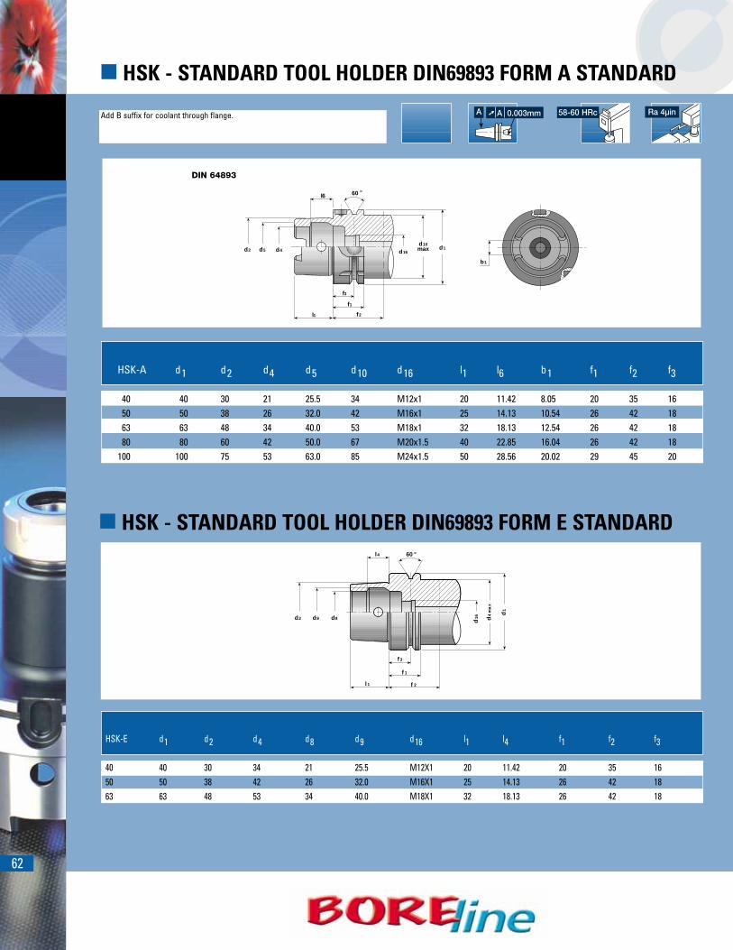
62
� HSK - STANDARD TOOL HOLDER DIN69893 FORM A STANDARD
Add B suffix for coolant through flange. Ra 4µin58-60 HRc
b1
l6
f3
f1
f2l1
60 °
d1d10maxd16d4d5d2
HSK-A d1 d2 d4 d5 d10 d16 l1 l6 b1 f1 f2 f3
40 40 30 21 25.5 34 M12x1 20 11.42 8.05 20 35 1650 50 38 26 32.0 42 M16x1 25 14.13 10.54 26 42 1863 63 48 34 40.0 53 M18x1 32 18.13 12.54 26 42 1880 80 60 42 50.0 67 M20x1.5 40 22.85 16.04 26 42 18
100 100 75 53 63.0 85 M24x1.5 50 28.56 20.02 29 45 20
HSK-E d1 d2 d4 d8 d9 d16 l1 l4 f1 f2 f3
40 40 30 34 21 25.5 M12X1 20 11.42 20 35 1650 50 38 42 26 32.0 M16X1 25 14.13 26 42 1863 63 48 53 34 40.0 M18X1 32 18.13 26 42 18
d1
d4
ma
x
d16
f 3
f 1
f 2l 1
l4 60 °
d8d9d2
� HSK - STANDARD TOOL HOLDER DIN69893 FORM E STANDARD
DIN 64893
➚ A 0.003mmA

63
➚ A 0.003mmA
HSK DIN 69896 Form E
ER DIN 6499
Add B suffix for coolant through flange. Ra 4µin58-60 HRc
� HSK - ER COLLET CHUCK (METRIC) HSK E-ER16 / ER20 / ER25 / ER32
L1
J
L
DHSK
D1
L2
D
L1
L
* Balance G2.5 35.000 RPM.** Balance G2.5 30.000 RPM.Coolant tube not included.
ER25,32 ER16,20
Designation HSK-E Range D D1 L L1 L2 J
HSK E 40 ER16X 60 40 0.5-10 28 - 60 40 - -HSK E 40 ER16X 80 40 0.5-10 28 - 80 60 - M10HSK E 40 ER20X 80 40 1.0-13 34 - 80 60 - M12HSK E 40 ER25X 80 40 1.0-16 42 34.0 80 60 28 M18x1.5HSK E 40 ER32X 80 40 2.0-20 50 40.1 80 60 31 M22x1.5HSK E 50 ER16X 80 * 50 0.5-10 28 - 80 54 - M10HSK E 50 ER16X 100 * 50 0.5-10 28 - 100 74 - M10HSK E 50 ER20X 80 * 50 1.0-13 34 - 80 54 - M10HSK E 50 ER25X 80 * 50 1.0-16 42 32.4 80 54 28 -HSK E 50 ER32X 80 * 50 2.0-20 50 40.4 80 54 31 -HSK E 50 ER32X 100 * 50 2.0-20 50 40.4 100 74 31 M22x1.5HSK E 63 ER16X 80 ** 63 0.5-10 28 - 80 54 - M10HSK E 63 ER16X 100 ** 63 0.5-10 28 - 100 74 - M10HSK E 63 ER32X 80 ** 63 2.0-20 50 40.4 80 54 31 -HSK E 63 ER32X 100 ** 63 2.0-20 50 100 75 - M22x1.5
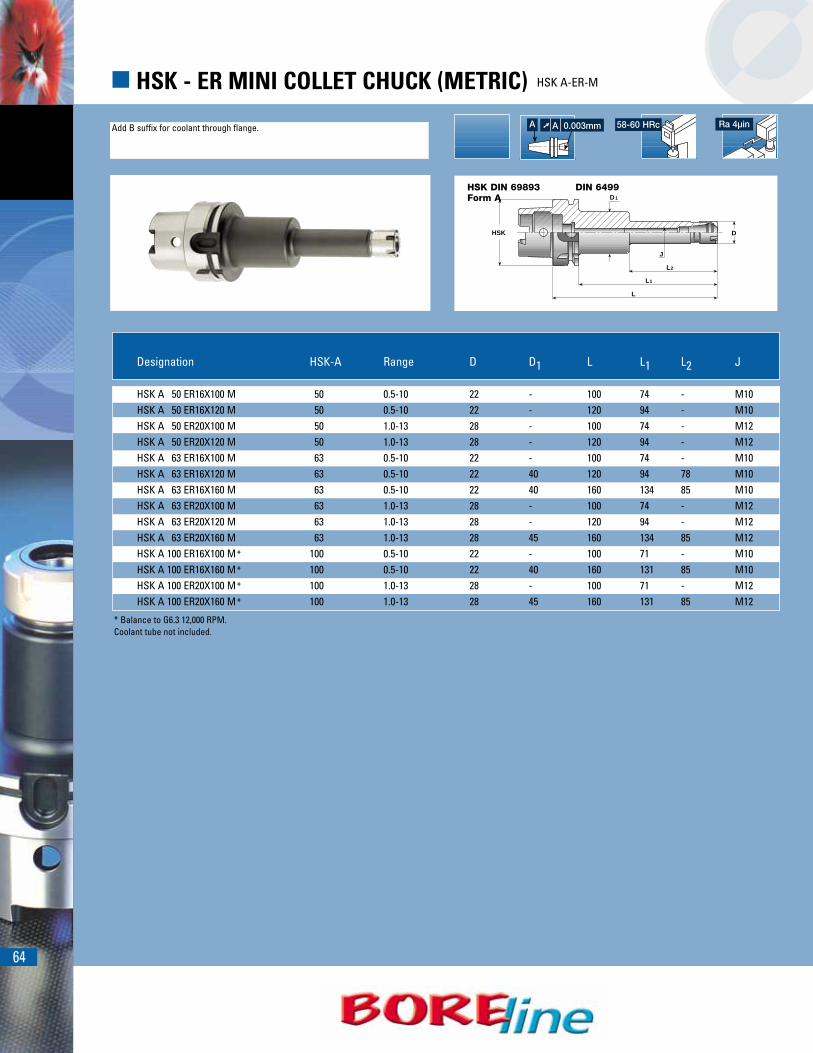
64
� HSK - ER MINI COLLET CHUCK (METRIC) HSK A-ER-M
HSK DIN 69893Form A
DIN 6499
Add B suffix for coolant through flange. Ra 4µin58-60 HRc
L2
D1
HSK
L
J
D
L1
* Balance to G6.3 12,000 RPM.Coolant tube not included.
Designation HSK-A Range D D1 L L1 L2 J
HSK A 50 ER16X100 M 50 0.5-10 22 - 100 74 - M10HSK A 50 ER16X120 M 50 0.5-10 22 - 120 94 - M10HSK A 50 ER20X100 M 50 1.0-13 28 - 100 74 - M12HSK A 50 ER20X120 M 50 1.0-13 28 - 120 94 - M12HSK A 63 ER16X100 M 63 0.5-10 22 - 100 74 - M10HSK A 63 ER16X120 M 63 0.5-10 22 40 120 94 78 M10HSK A 63 ER16X160 M 63 0.5-10 22 40 160 134 85 M10HSK A 63 ER20X100 M 63 1.0-13 28 - 100 74 - M12HSK A 63 ER20X120 M 63 1.0-13 28 - 120 94 - M12HSK A 63 ER20X160 M 63 1.0-13 28 45 160 134 85 M12HSK A 100 ER16X100 M* 100 0.5-10 22 - 100 71 - M10HSK A 100 ER16X160 M* 100 0.5-10 22 40 160 131 85 M10HSK A 100 ER20X100 M* 100 1.0-13 28 - 100 71 - M12HSK A 100 ER20X160 M* 100 1.0-13 28 45 160 131 85 M12
➚ A 0.003mmA
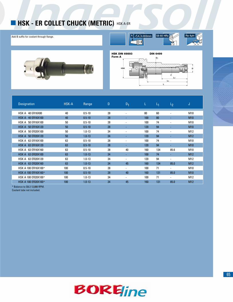
65
HSK DIN 69893Form A
DIN 6499
Add B suffix for coolant through flange. Ra 4µin58-60 HRc
� HSK - ER COLLET CHUCK (METRIC) HSK A-ER
L2
D1
HSK
L
J
D
L1
* Balance to G6.3 12,000 RPM.Coolant tube not included.
Designation HSK-A Range D D1 L L1 L2 J
HSK A 40 ER16X80 40 0.5-10 28 - 80 60 - M10HSK A 40 ER16X100 40 0.5-10 28 - 100 80 - M10HSK A 50 ER16X100 50 0.5-10 28 - 100 74 - M10HSK A 50 ER16X120 50 0.5-10 28 - 120 94 - M10HSK A 50 ER20X100 50 1.0-13 34 - 100 74 - M12HSK A 50 ER20X120 50 1.0-13 34 - 120 94 - M12HSK A 63 ER16X100 63 0.5-10 28 - 100 74 - M10HSK A 63 ER16X120 63 0.5-10 28 - 120 94 - M10HSK A 63 ER16X160 63 0.5-10 28 40 160 134 85.6 M10HSK A 63 ER20X100 63 1.0-13 34 - 100 74 - M12HSK A 63 ER20X120 63 1.0-13 34 - 120 94 - M12HSK A 63 ER20X160 63 1.0-13 34 45 160 134 85.0 M12HSK A 100 ER16X100* 100 0.5-10 28 - 100 71 - M10HSK A 100 ER16X160* 100 0.5-10 28 40 160 131 85.0 M10HSK A 100 ER20X100* 100 1.0-13 34 - 100 71 - M12HSK A 100 ER20X160* 100 1.0-13 34 45 160 131 85.0 M12
➚ A 0.003mmA

66
� HSK - ER COLLET CHUCK (METRIC) HSK A-ER
HASK DIN 69893Form A
DIN 6499
Add B suffix for coolant through flange.
D
LL1
HSK
J L2
D1
Designation HSK-A Range D D1 L L1 L2 J
HSK A 40 ER25X80 40 1-16 42 32.4 80 60 28.0 M18x1.5HSK A 40 ER25X100 40 1-16 42 32.4 100 80 28.0 M16HSK A 40 ER32X100 40 2-20 50 40.4 100 80 31.0 M22x1.5HSK A 50 ER25X 80 50 1-16 42 32.4 80 54 28.0 M16HSK A 50 ER25X100 50 1-16 42 41.8 100 74 28.5 M16HSK A 50 ER32X100 50 2-20 50 40.4 100 74 31.0 M22x1.5HSK A 50 ER32X120 50 2-20 50 41.8 120 94 35.0 M22x1.5HSK A 63 ER25X 80 63 1-16 42 - 80 54 - M16HSK A 63 ER25X100 63 1-16 42 - 100 74 - M16HSK A 63 ER25X120 63 1-16 42 - 120 94 - M16HSK A 63 ER25X160 63 1-16 42 - 160 134 - M16HSK A 63 ER32X 80 63 2-20 50 40.4 80 54 31.0 M22x1.5HSK A 63 ER32X100 63 2-20 50 - 100 74 - M22x1.5HSK A 63 ER32X120 63 2-20 50 - 120 94 - M22x1.5HSK A 63 ER32X140 63 2-20 50 - 140 114 - M22x1.5HSK A 63 ER32X160 63 2-20 50 - 160 134 - M22x1.5HSK A 63 ER40X 80 63 3-26 63 50.4 80 54 34.0 M28x1.5HSK A 63 ER40X100 63 3-26 63 50.4 100 74 34.0 M28x1.5HSK A 63 ER40X120 63 3-26 63 50.4 120 94 34.0 M28x1.5
Ra 4µin58-60 HRc
Coolant tube not included.
➚ A 0.003mmA
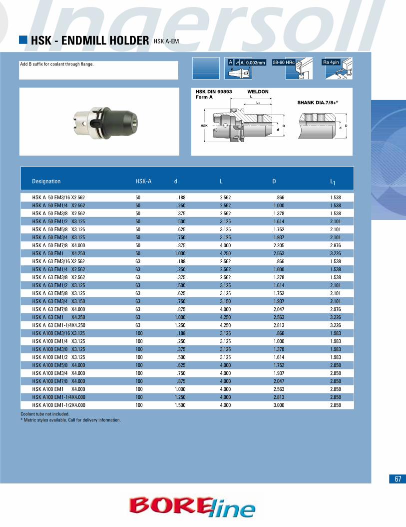
➚ A .00020A
67
HSK DIN 69893Form A
WELDON
Add B suffix for coolant through flange. Ra 4µin58-60 HRc
� HSK - ENDMILL HOLDER HSK A-EM
HSK
L1
L
dD
dD
SHANK DIA.7/8+”
Designation HSK-A d L D L1
HSK A 50 EM3/16 X2.562 50 .188 2.562 .866 1.538HSK A 50 EM1/4 X2.562 50 .250 2.562 1.000 1.538HSK A 50 EM3/8 X2.562 50 .375 2.562 1.378 1.538HSK A 50 EM1/2 X3.125 50 .500 3.125 1.614 2.101HSK A 50 EM5/8 X3.125 50 .625 3.125 1.752 2.101HSK A 50 EM3/4 X3.125 50 .750 3.125 1.937 2.101HSK A 50 EM7/8 X4.000 50 .875 4.000 2.205 2.976HSK A 50 EM1 X4.250 50 1.000 4.250 2.563 3.226HSK A 63 EM3/16 X2.562 63 .188 2.562 .866 1.538HSK A 63 EM1/4 X2.562 63 .250 2.562 1.000 1.538HSK A 63 EM3/8 X2.562 63 .375 2.562 1.378 1.538HSK A 63 EM1/2 X3.125 63 .500 3.125 1.614 2.101HSK A 63 EM5/8 X3.125 63 .625 3.125 1.752 2.101HSK A 63 EM3/4 X3.150 63 .750 3.150 1.937 2.101HSK A 63 EM7/8 X4.000 63 .875 4.000 2.047 2.976HSK A 63 EM1 X4.250 63 1.000 4.250 2.563 3.226HSK A 63 EM1-1/4X4.250 63 1.250 4.250 2.813 3.226HSK A100 EM3/16 X3.125 100 .188 3.125 .866 1.983HSK A100 EM1/4 X3.125 100 .250 3.125 1.000 1.983HSK A100 EM3/8 X3.125 100 .375 3.125 1.378 1.983HSK A100 EM1/2 X3.125 100 .500 3.125 1.614 1.983HSK A100 EM5/8 X4.000 100 .625 4.000 1.752 2.858HSK A100 EM3/4 X4.000 100 .750 4.000 1.937 2.858HSK A100 EM7/8 X4.000 100 .875 4.000 2.047 2.858HSK A100 EM1 X4.000 100 1.000 4.000 2.563 2.858HSK A100 EM1-1/4X4.000 100 1.250 4.000 2.813 2.858HSK A100 EM1-1/2X4.000 100 1.500 4.000 3.000 2.858
Coolant tube not included.* Metric styles available. Call for delivery information.
➚ A 0.003mmA
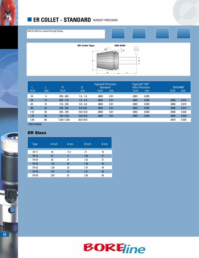
68
� ER COLLET - STANDARD RUNOUT PRECISION
ER Collet Type DIN 6499
Add B suffix for coolant through flange.
LB
A D
8˚30˚
ER Sizes
*ER50 DIN6499
Ingersoll Precision Ingersoll “AA”L L D D Standard Ultra Precision DIN 6499*
Inch mm Inch mm Inch mm Inch mm Inch mm
.24 6 .039- .063 1.0- 1.6 .0004 0.01 .0002 0.005
.39 10 .063- .118 1.6- 3.0 .0004 0.01 .0002 0.005 .0006 0.015
.63 16 .118- .236 3.0- 6.0 .0004 0.01 .0002 0.005 .0006 0.015
.98 25 .236- .394 6.0-10.0 .0004 0.01 .0002 0.005 .0006 0.0151.57 40 .394- .709 10.0-18.0 .0004 0.01 .0002 0.005 .0008 0.0201.97 50 .709-1.024 18.0-26.0 .0004 0.01 .0002 0.005 .0008 0.0202.36 60 1.024-1.339 26.0-34.0 .0010 0.025
Type A Inch A mm B Inch B mm
ER-11 .45 11.5 .71 18ER-16 .67 17 1.06 27ER-20 .83 21 1.22 31ER-25 1.02 26 1.38 35ER-32 1.30 33 1.57 40ER-40 1.61 41 1.81 46ER-50 2.05 52 2.36 60

69
� ER COLLET - SEALED COLLET
Application:For use with solid and coolant through tools.Ideal for high speed machining as well as con-ventional machining. Can be used on machiningcenters, lathes and other machine types.
Features:• Front sealed design• .040” (1mm) range • Improved coolant delivery can increase tool life• Two styles available: ER JET and JET2
Advantages:• Can be used with high pressure coolant
1450 PSI max.• Designed for use with Weldon shanks,
cylindrical shanks and whistle notch styles.
Notes:• Minimum clamping length: 2X shank diameter,
to insure minimum run-out and maximumclamping.
• When using JET2 style collets, tool should berotated to direct coolant flow to flutes foroptimum chip evacuation.

70
� ER COLLET - ER COOLIT SEALED COLLET
Two types:
Sealed Collet jet For straight shank cuttingtools with coolant through.
Sealed Collet jet2 With angular double nozzle.Coolant flow should bedirected to flutes of cuttingtool.
Shank Standards
Cylindrical Shank Weldon/DIN 1835/B
Whistle Notch

71
� ER COLLET - ER TOP CLAMPING NUT DIN 6499
Description:Precision ER retention nut. Two-piece designincorporating a specialized, two-piece frictionmechanism which is self centering.
Features:
• Friction/bearing design offers 50%-100%greater torque transfer than conventional ERcollet chucks.
• Balanced, allowing much higher RPM, due tounique extractor teeth.
• Compact style, no longer than standard ERretention nut.
• Designed for use with sealed collets.
Operation:Always insert collet INTO nut BEFORE threading nut onto the collet chuck.
Assembly Procedure:1. Angle collet into nut, inserting the extract
teeth into the groove on collet. 2. Place collet/nut onto a flat work surface.3. Press collet into nut until it “snaps” into place;
thread collet/nut onto collet chuck; insert toolshank and tighten to proper torque for that sizecollet.
Collet Groove
Extractor Teeth
Extractor Teeth
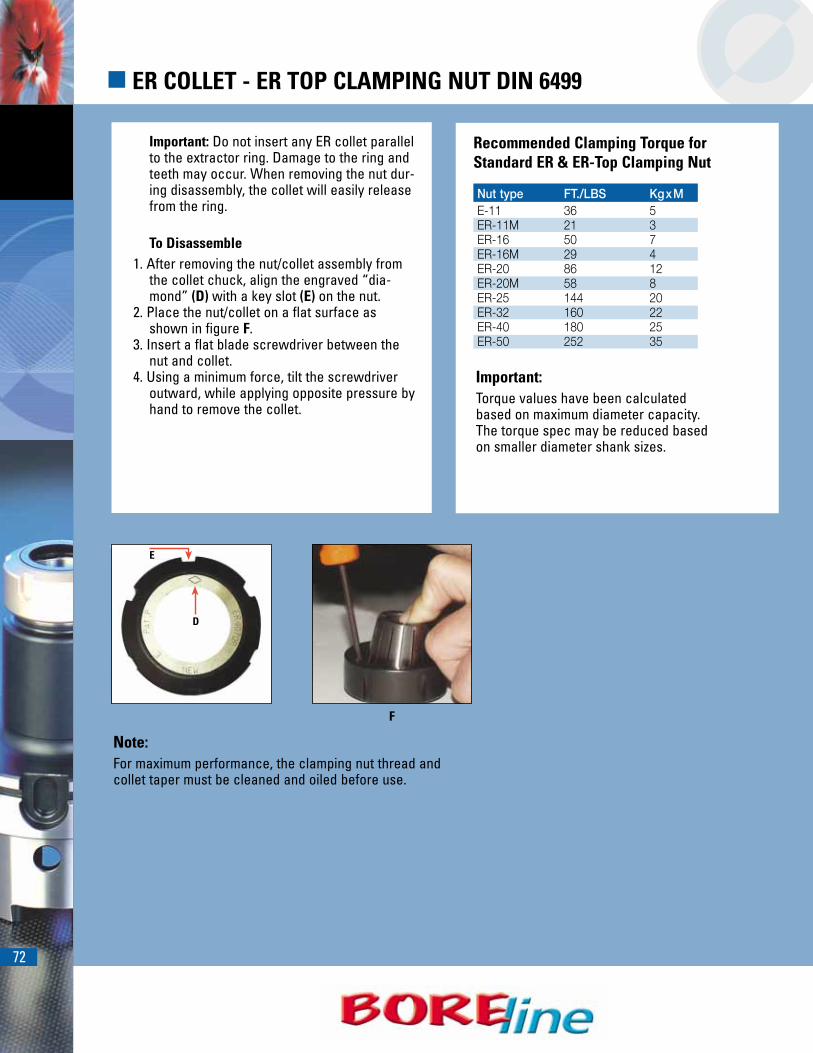
72
� ER COLLET - ER TOP CLAMPING NUT DIN 6499
Note:For maximum performance, the clamping nut thread andcollet taper must be cleaned and oiled before use.
Recommended Clamping Torque forStandard ER & ER-Top Clamping Nut
Nut type FT./LBS KgxME-11 36 5ER-11M 21 3ER-16 50 7ER-16M 29 4ER-20 86 12ER-20M 58 8ER-25 144 20ER-32 160 22ER-40 180 25ER-50 252 35
Important:Torque values have been calculatedbased on maximum diameter capacity.The torque spec may be reduced basedon smaller diameter shank sizes.
Important: Do not insert any ER collet parallelto the extractor ring. Damage to the ring andteeth may occur. When removing the nut dur-ing disassembly, the collet will easily releasefrom the ring.
To Disassemble1. After removing the nut/collet assembly from
the collet chuck, align the engraved “dia-mond” (D) with a key slot (E) on the nut.
2. Place the nut/collet on a flat surface asshown in figure F.
3. Insert a flat blade screwdriver between thenut and collet.
4. Using a minimum force, tilt the screwdriveroutward, while applying opposite pressure byhand to remove the collet.
F
E
D

73
� ER COLLET - ER SPRING COLLETS DIN 6499
ER-11,16,20,25-SPR
ER32,40-SPR
Diameter DiameterDesignation Range Range (mm)
ER11 SPR .022-.041 1/32 (.022-.041) 0.5-1ER11 SPR .041-.080 1/16 (.041-.080) 1-2ER11 SPR .080-.120 3/32 (.080-.120) 2-3ER11 SPR .120-.159 1/8 (.120-.159) 3-4ER11 SPR .159-.199 3/16 (.159-.199) 4-5ER11 SPR .199-.238 7/32 (.199-.238) 5-6ER11 SPR .238-.278 1/4 (.238-.278) 6-7ER16 SPR .022-.041 1/32 (.022-.041) 0.5-1ER16 SPR .041-.080 1/16 (.041-.080) 1-2ER16 SPR .080-.120 3/32 (.080-.120) 2-3ER16 SPR .120-.159 1/8 (.120-.159) 3-4ER16 SPR .159-.199 3/16 (.159-.199) 4-5ER16 SPR .199-.238 7/32 (.199-.238) 5-6ER16 SPR .238-.278 1/4 (.238-.278) 6-7ER16 SPR .278-.317 5/16 (.278-.317) 7-8ER16 SPR .317-.356 11/32 (.317-.356) 8-9ER16 SPR .356-.396 3/8 (.356-.396 9-10ER20 SPR .041-.080 1/16 (.041-.080) 1-2ER20 SPR .080-.120 3/32 (.080-.120) 2-3ER20 SPR .120-.159 1/8 (.120-.159) 3-4ER20 SPR .159-.199 3/16 (.159-.199) 4-5ER20 SPR .199-.238 7/32 (.199-.238) 5-6ER20 SPR .238-.278 1/4 (.238-.278) 6-7ER20 SPR .278-.317 5/16 (.278-.317) 7-8ER20 SPR .317-.356 11/32 (.317-.356) 8-9ER20 SPR .356-.396 3/8 (.356-.396 9-10ER20 SPR .396-.435 13/32 (.396-.435) 10-11ER20 SPR .435-.474 7/16 (.435-.474) 11-12ER20 SPR .474-.514 1/2 (.474-.514) 12-13ER25 SPR .041-.080 1/16 (.041-.080) 1-2ER25 SPR .080-.120 3/32 (.080-.120) 2-3ER25 SPR .120-.159 1/8 (.120-.159) 3-4ER25 SPR .159-.199 3/16 (.159-.199) 4-5ER25 SPR .199-.238 7/32 (.199-.238) 5-6ER25 SPR .238-.278 1/4 (.238-.278) 6-7ER25 SPR .278-.317 5/16 (.278-.317) 7-8ER25 SPR .317-.356 11/32 (.317-.356) 8-9ER25 SPR .356-.396 3/8 (.356-.396 9-10ER25 SPR .396-.435 13/32 (.396-.435) 10-11ER25 SPR .435-.474 7/16 (.435-.474) 11-12ER25 SPR .474-.514 1/2 (.474-.514) 12-13ER25 SPR .514-.553 17/32 (.514-.553) 13-14ER25 SPR .553-.593 9/16 (.553-.593) 14-15ER25 SPR .593-.632 5/8 (.593-.632) 15-16
Diameter DiameterDesignation Range Range (mm)
ER32 SPR .080-.120 3/32 (.080-.120) 2-3ER32 SPR .120-.159 1/8 (.120-.159) 3-4ER32 SPR .159-.199 3/16 (.159-.199) 4-5ER32 SPR .199-.238 7/32 (.199-.238) 5-6ER32 SPR .238-.278 1/4 (.238-.278) 6-7ER32 SPR .278-.317 5/16 (.278-.317) 7-8ER32 SPR .317-.356 11/32 (.317-.356) 8-9ER32 SPR .356-.396 3/8 (.356-.396 9-10ER32 SPR .396-.435 13/32 (.396-.435) 10-11ER32 SPR .435-.474 7/16 (.435-.474) 11-12ER32 SPR .474-.514 1/2 (.474-.514) 12-13ER32 SPR .514-.553 17/32 (.514-.553) 13-14ER32 SPR .553-.593 9/16 (.553-.593) 14-15ER32 SPR .593-.632 5/8 (.593-.632) 15-16ER32 SPR .632-.671 21/32 (.632-.671) 16-17ER32 SPR .671-.711 11/16 (.671-.711) 17-18ER32 SPR .711-.750 3/4 (.711-.750) 18-19ER32 SPR .750-.789 25/32 (.750-.789) 19-20ER40 SPR .120-.159 1/8 (.120-.159) 3-4ER40 SPR .159-.199 3/16 (.159-.199) 4-5ER40 SPR .199-.238 7/32 (.199-.238) 5-6ER40 SPR .238-.278 1/4 (.238-.278) 6-7ER40 SPR .278-.317 5/16 (.278-.317) 7-8ER40 SPR .317-.356 11/32 (.317-.356) 8-9ER40 SPR .356-.396 3/8 (.356-.396 9-10ER40 SPR .396-.435 13/32 (.396-.435) 10-11ER40 SPR .435-.474 7/16 (.435-.474) 11-12ER40 SPR .474-.514 1/2 (.474-.514) 12-13ER40 SPR .514-.553 17/32 (.514-.553) 13-14ER40 SPR .553-.593 9/16 (.553-.593) 14-15ER40 SPR .593-.632 5/8 (.593-.632) 15-16ER40 SPR .632-.671 21/32 (.632-.671) 16-17ER40 SPR .671-.711 11/16 (.671-.711) 17-18ER40 SPR .711-.750 3/4 (.711-.750) 18-19ER40 SPR .750-.789 25/32 (.750-.789) 19-20ER40 SPR .789-.829 13/16 (.789-.829) 20-21ER40 SPR .829-.868 27/32 (.829-.868) 21-22ER40 SPR .868-.907 7/8 (.868-.907) 22-23ER40 SPR .907-.947 15/16 (.907-.947) 23-24ER40 SPR .947-.986 31/32 (.947-.986) 24-25ER40 SPR .986-1.025 1 (.986-1.025) 25-26
Ra 4µin
46-48 HRc
.0004
74
� ER COLLET - ER SPRING COLLETS DIN 6499
ER50-SPR ER-EX* (Single-diameter spring collets)
* Recommended for improved runout and clamping torque.
Diameter DiameterDesignation Range Range (mm)
ER50 SPR .396-.474 13/32, 7/16 (.396-.474) 10-12ER50 SPR .474-.553 1/2, 17/32 (.474-.553) 12-14ER50 SPR .553-.632 9/16, 5/8 (.553-.632) 14-16ER50 SPR .632-.711 21/32, 11/16 (.632-.711) 16-18ER50 SPR .711-.789 3/4, 25/32 (.711-.789) 18-20ER50 SPR .789-.868 13/16, 27/32 (.789-.868) 20-22ER50 SPR .868-.947 7/8, 15/16 (.868-.947) 22-24ER50 SPR .947-1.025 31/32, 1 (.947-1.025) 24-26ER50 SPR 1.025-1.102 1-1/16 (1.025-1.102) 26-28ER50 SPR 1.102-1.181 1-1/8 (1.102-1.181) 28-30ER50 SPR 1.181-1.260 1-1/4 (1.181-1.260) 30-32ER50 SPR 1.260-1.338 1-5/16 (1.260-1.338) 32-34
DiameterDesignation Diameter Range (mm)
ER32 EX .125 .125 (1/8) 3.175ER32 EX .250 .250 (1/4) 6.350ER32 EX .312 .312 (5/16) 7.924ER32 EX .375 .375 (3/8) 9.525ER32 EX .500 .500 (1/2) 12.700ER32 EX .625 .625 (5/8) 15.875ER32 EX .750 .750 (3/4) 19.050ER40 EX .250 .250 (1/4) 6.350ER40 EX .312 .312 (5/16) 7.924ER40 EX .375 .375 (3/8) 9.525ER40 EX .500 .500 (1/2) 12.700ER40 EX .625 .625 (5/8) 15.875ER40 EX .750 .750 (3/4) 19.050ER40 EX .875 .875 (7/8) 22.225ER40 EX 1.000 1.000 25.400
Ra 4µin
46-48 HRc
.0004

75
� ER COLLET - ER SPRING COLLETS DIN 6499
ER11,16,20-SPR-AA ER25,32-SPR-AA
Diameter DiameterDesignation Range Range (mm)
ER11 SPR .022-.041 AA 1/32 (.022-.041) 0.5-1ER11 SPR .041-.080 AA 1/16 (.041-.080) 1-2ER11 SPR .080-.120 AA 3/32 (.080-.120) 2-3ER11 SPR .120-.159 AA 1/8 (.120-.159) 3-4ER11 SPR .159-.199 AA 3/16 (.159-.199) 4-5ER11 SPR .199-.238 AA 7/32 (.199-.238) 5-6ER11 SPR .238-.278 AA 1/4 (.238-.278) 6-7ER16 SPR .022-.041 AA 1/32 (.022-.041) 0.5-1ER16 SPR .041-.080 AA 1/16 (.041-.080) 1-2ER16 SPR .080-.120 AA 3/32 (.080-.120) 2-3ER16 SPR .120-.159 AA 1/8 (.120-.159) 3-4ER16 SPR .159-.199 AA 3/16 (.159-.199) 4-5ER16 SPR .199-.238 AA 7/32 (.199-.238) 5-6ER16 SPR .238-.278 AA 1/4 (.238-.278) 6-7ER16 SPR .278-.317 AA 5/16 (.278-.317) 7-8ER16 SPR .317-.356 AA 11/32 (.317-.356) 8-9ER16 SPR .356-.396 AA 3/8 (.356-.396 9-10ER20 SPR .041-.080 AA 1/16 (.041-.080) 1-2ER20 SPR .080-.120 AA 3/32 (.080-.120) 2-3ER20 SPR .120-.159 AA 1/8 (.120-.159) 3-4ER20 SPR .159-.199 AA 3/16 (.159-.199) 4-5ER20 SPR .199-.238 AA 7/32 (.199-.238) 5-6ER20 SPR .238-.278 AA 1/4 (.238-.278) 6-7ER20 SPR .278-.317 AA 5/16 (.278-.317) 7-8ER20 SPR .317-.356 AA 11/32 (.317-.356) 8-9ER20 SPR .356-.396 AA 3/8 (.356-.396 9-10ER20 SPR .396-.435 AA 13/32 (.396-.435) 10-11ER20 SPR .435-.474 AA 7/16 (.435-.474) 11-12ER20 SPR .474-.514 AA 1/2 (.474-.514) 12-13
Diameter DiameterDesignation Range Range (mm)
ER25 SPR .041-.080 AA 1/16 (.041-.080) 1-2ER25 SPR .080-.120 AA 3/32 (.080-.120) 2-3ER25 SPR .120-.159 AA 1/8 (.120-.159) 3-4ER25 SPR .159-.199 AA 3/16 (.159-.199) 4-5ER25 SPR .199-.238 AA 7/32 (.199-.238) 5-6ER25 SPR .238-.278 AA 1/4 (.238-.278) 6-7ER25 SPR .278-.317 AA 5/16 (.278-.317) 7-8ER25 SPR .317-.356 AA 11/32 (.317-.356) 8-9ER25 SPR .356-.396 AA 3/8 (.356-.396 9-10ER25 SPR .396-.435 AA 13/32 (.396-.435) 10-11ER25 SPR .435-.474 AA 7/16 (.435-.474) 11-12ER25 SPR .474-.514 AA 1/2 (.474-.514) 12-13ER25 SPR .514-.553 AA 17/32 (.514-.553) 13-14ER25 SPR .553-.593 AA 9/16 (.553-.593) 14-15ER25 SPR .593-.632 AA 5/8 (.593-.632) 15-16ER32 SPR .080-.120 AA 3/32 (.080-.120) 2-3ER32 SPR .120-.159 AA 1/8 (.120-.159) 3-4ER32 SPR .159-.199 AA 3/16 (.159-.199) 4-5ER32 SPR .199-.238 AA 7/32 (.199-.238) 5-6ER32 SPR .238-.278 AA 1/4 (.238-.278) 6-7ER32 SPR .278-.317 AA 5/16 (.278-.317) 7-8ER32 SPR .317-.356 AA 11/32 (.317-.356) 8-9ER32 SPR .356-.396 AA 3/8 (.356-.396 9-10ER32 SPR .396-.435 AA 13/32 (.396-.435) 10-11ER32 SPR .435-.474 AA 7/16 (.435-.474) 11-12ER32 SPR .474-.514 AA 1/2 (.474-.514) 12-13ER32 SPR .514-.553 AA 17/32 (.514-.553) 13-14ER32 SPR .553-.593 AA 9/16 (.553-.593) 14-15ER32 SPR .593-.632 AA 5/8 (.593-.632) 15-16ER32 SPR .632-.671 AA 21/32 (.632-.671) 16-17ER32 SPR .671-.711 AA 11/16 (.671-.711) 17-18ER32 SPR .711-.750 AA 3/4 (.711-.750) 18-19ER32 SPR .750-.789 AA 25/32 (.750-.789) 19-20
Ra 4µin
46-48 HRc
.0002
ULTRAPRECISION‘AA’
76
� ER COLLET - ER SPRING COLLETS DIN 6499 “AA”
Diameter DiameterDesignation Range Range (mm)
ER40 SPR .120-.159 AA 1/8 (.120-.159) 3-4ER40 SPR .159-.199 AA 3/16 (.159-.199) 4-5ER40 SPR .199-.238 AA 7/32 (.199-.238) 5-6ER40 SPR .238-.278 AA 1/4 (.238-.278) 6-7ER40 SPR .278-.317 AA 5/16 (.278-.317) 7-8ER40 SPR .317-.356 AA 11/32 (.317-.356) 8-9ER40 SPR .356-.396 AA 3/8 (.356-.396 9-10ER40 SPR .396-.435 AA 13/32 (.396-.435) 10-11ER40 SPR .435-.474 AA 7/16 (.435-.474) 11-12ER40 SPR .474-.514 AA 1/2 (.474-.514) 12-13ER40 SPR .514-.553 AA 17/32 (.514-.553) 13-14ER40 SPR .553-.593 AA 9/16 (.553-.593) 14-15ER40 SPR .593-.632 AA 5/8 (.593-.632) 15-16ER40 SPR .632-.671 AA 21/32 (.632-.671) 16-17ER40 SPR .671-.711 AA 11/16 (.671-.711) 17-18ER40 SPR .711-.750 AA 3/4 (.711-.750) 18-19ER40 SPR .750-.789 AA 25/32 (.750-.789) 19-20ER40 SPR .789-.829 AA 13/16 (.789-.829) 20-21ER40 SPR .829-.868 AA 27/32 (.829-.868) 21-22ER40 SPR .868-.907 AA 7/8 (.868-.907) 22-23ER40 SPR .907-.947 AA 15/16 (.907-.947) 23-24ER40 SPR .947-.986 AA 31/32 (.947-.986) 24-25ER40 SPR .986-1.025 AA 1 (.986-1.025) 25-26
ULTRAPRECISION‘AA’
Ra 4µin46-48 HRc
.0002
77
� TG100 COLLET - TG100 + SPRING COLLET
TG100+-SPR
(1)Expanded collapsability range (.04”)
SET-TG100+-SPR Spring Collets
Diameter DiameterDesignation Range Range (mm)
TG100+ SPR .093-.150 1/8, 9/64 (.093-.150) 2.5-3.5TG100+ SPR .150-.199 5/32, 11/64, 3/16 (.150-.199) 4-5TG100+ SPR .199-.238 13/64, 7/32, 15/64 (.199-.238) 5-6TG100+ SPR .238-.278 1/4, 17/64 (.238-.278) 6-7TG100+ SPR .278-.317 9/32, 19/64, 5/16 (.278-.317) 7-8TG100+ SPR .317-.356 21/64, 11/32 (.317-.356) 8-9TG100+ SPR .356-.396 23/64, 3/8, 25/64 (.356-.396) 9-10TG100+ SPR .396-.435 13/32, 27/64 (.396-.435) 10-11TG100+ SPR .435-.474 7/16, 29/64, 15/32 (.435-.474) 11-12TG100+ SPR .474-.514 31/64, 1/2 (.474-.514) 12-13TG100+ SPR .514-.553 33/64, 17/32, 35/64 (.514-.553) 13-14TG100+ SPR .553-.593 9/16, 37/64, 19/32 (.553-.593) 14-15TG100+ SPR .593-.632 39/64, 5/8 (.593-.632) 15-16TG100+ SPR .632-.671 41-64, 21-32, 43/64 (.632-.671) 16-17TG100+ SPR .671-.711 11/16, 45/64 (.671-.711) 17-18TG100+ SPR .711-.750 23/32, 47/32, 3/4 (.711-.750) 18-19TG100+ SPR .750-.789 49/64, 25/32 (.750-.789) 19-20TG100+ SPR .789-.829 51/64, 13/16, 53/64 (.789-.829) 20-21TG100+ SPR .829-.868 27/32, 55/64 (.829-.868) 21-22TG100+ SPR .868-.907 7/8, 57/64, 29/32 (.868-.907) 22-23TG100+ SPR .907-.947 59/64, 15/16 (.907-.947) 23-24TG100+ SPR .947-.986 61/64, 31/32, 63/64 (.947-.986) 24-25TG100+ SPR .986-1.025 1 (.986-1.025) 25-26
Diameter DiameterDesignation Range Range (mm) Pcs.
SET TG100+ SPR .093-1.025 23 1/8-1 (.093-1.025) 2.5-26 23SET TG100+ SPR .093-.514 10 1/8-1/2 (.093-.514) 2.5-13 10SET TG100+ SPR .511-1.025 13 33/64-1 (.511-1.025) 13-26 13
Ra 4µin
46-48 HRc
.0004
ULTRAPRECISION‘AA’
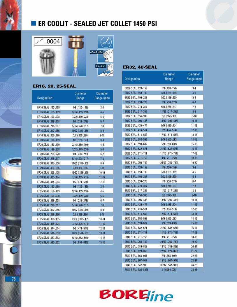
78
� ER COOLIT - SEALED JET COLLET 1450 PSI
ER32, 40-SEAL
ER16, 20, 25-SEAL
Diameter DiameterDesignation Range Range (mm)
ER16 SEAL .120-.159 1/8 (.120-.159) 3-4ER16 SEAL .159-.199 3/16 (.159-.199) 4-5ER16 SEAL .199-.238 7/32 (.199-.238) 5-6ER16 SEAL .238-.278 1/4 (.238-.278) 6-7ER16 SEAL .278-.317 5/16 (.278-.317) 7-8ER16 SEAL .317-.356 11/32 (.317-.356) 8-9ER16 SEAL .356-.396 3/8 (.356-.396 9-10ER20 SEAL .120-.159 1/8 (.120-.159) 3-4ER20 SEAL .159-.199 3/16 (.159-.199) 4-5ER20 SEAL .199-.238 7/32 (.199-.238) 5-6ER20 SEAL .238-.278 1/4 (.238-.278) 6-7ER20 SEAL .278-.317 5/16 (.278-.317) 7-8ER20 SEAL .317-.356 11/32 (.317-.356) 8-9ER20 SEAL .356-.396 3/8 (.356-.396 9-10ER20 SEAL .396-.435 13/32 (.396-.435) 10-11ER20 SEAL .435-.474 7/16 (.435-.474) 11-12ER20 SEAL .474-.514 1/2 (.474-.514) 12-13ER25 SEAL .120-.159 1/8 (.120-.159) 3-4ER25 SEAL .159-.199 3/16 (.159-.199) 4-5ER25 SEAL .199-.238 7/32 (.199-.238) 5-6ER25 SEAL .238-.278 1/4 (.238-.278) 6-7ER25 SEAL .278-.317 5/16 (.278-.317) 7-8ER25 SEAL .317-.356 11/32 (.317-.356) 8-9ER25 SEAL .356-.396 3/8 (.356-.396 9-10ER25 SEAL .396-.435 13/32 (.396-.435) 10-11ER25 SEAL .435-.474 7/16 (.435-.474) 11-12ER25 SEAL .474-.514 1/2 (.474-.514) 12-13ER25 SEAL .514-.553 17/32 (.514-.553) 13-14ER25 SEAL .553-.593 9/16 (.553-.593) 14-15ER25 SEAL .593-.632 5/8 (.593-.632) 15-16
Diameter DiameterDesignation Range Range (mm)
ER32 SEAL .120-.159 1/8 (.120-.159) 3-4ER32 SEAL .159-.199 3/16 (.159-.199) 4-5ER32 SEAL .199-.238 7/32 (.199-.238) 5-6ER32 SEAL .238-.278 1/4 (.238-.278) 6-7ER32 SEAL .278-.317 5/16 (.278-.317) 7-8ER32 SEAL .317-.356 11/32 (.317-.356) 8-9ER32 SEAL .356-.396 3/8 (.356-.396 9-10ER32 SEAL .396-.435 13/32 (.396-.435) 10-11ER32 SEAL .435-.474 7/16 (.435-.474) 11-12ER32 SEAL .474-.514 1/2 (.474-.514) 12-13ER32 SEAL .514-.553 17/32 (.514-.553) 13-14ER32 SEAL .553-.593 9/16 (.553-.593) 14-15ER32 SEAL .593-.632 5/8 (.593-.632) 15-16ER32 SEAL .632-.671 21/32 (.632-.671) 16-17ER32 SEAL .671-.711 11/16 (.671-.711) 17-18ER32 SEAL .711-.750 3/4 (.711-.750) 18-19ER32 SEAL .750-.789 25/32 (.750-.789) 19-20ER40 SEAL .120-.159 1/8 (.120-.159) 3-4ER40 SEAL .159-.199 3/16 (.159-.199) 4-5ER40 SEAL .199-.238 7/32 (.199-.238) 5-6ER40 SEAL .238-.278 1/4 (.238-.278) 6-7ER40 SEAL .278-.317 5/16 (.278-.317) 7-8ER40 SEAL .317-.356 11/32 (.317-.356) 8-9ER40 SEAL .356-.396 3/8 (.356-.396 9-10ER40 SEAL .396-.435 13/32 (.396-.435) 10-11ER40 SEAL .435-.474 7/16 (.435-.474) 11-12ER40 SEAL .474-.514 1/2 (.474-.514) 12-13ER40 SEAL .514-.553 17/32 (.514-.553) 13-14ER40 SEAL .553-.593 9/16 (.553-.593) 14-15ER40 SEAL .593-.632 5/8 (.593-.632) 15-16ER40 SEAL .632-.671 21/32 (.632-.671) 16-17ER40 SEAL .671-.711 11/16 (.671-.711) 17-18ER40 SEAL .711-.750 3/4 (.711-.750) 18-19ER40 SEAL .750-.789 25/32 (.750-.789) 19-20ER40 SEAL .789-.829 13/16 (.789-.829) 20-21ER40 SEAL .829-.868 27/32 (.829-.868) 21-22ER40 SEAL .868-.907 7/8 (.868-.907) 22-23ER40 SEAL .907-.947 15/16 (.907-.947) 23-24ER40 SEAL .947-.986 31/32 (.947-.986) 24-25ER40 SEAL .986-1.025 1 (.986-1.025) 25-26
.0004
Ra 4µin
46-48 HRc
1450 psi

79
� ER COOLIT - SEALED JET2 SPRING COLLETS 1450 PSI
Diameter DiameterDesignation Range Range (mm)
ER16 SEAL .120-.159 JET2 1/8 (.120-.159) 3-4ER16 SEAL .159-.199 JET2 3/16 (.159-.199) 4-5ER16 SEAL .199-.238 JET2 7/32 (.199-.238) 5-6ER16 SEAL .238-.278 JET2 1/4 (.238-.278) 6-7ER16 SEAL .278-.317 JET2 5/16 (.278-.317) 7-8ER16 SEAL .317-.356 JET2 11/32 (.317-.356) 8-9ER16 SEAL .356-.396 JET2 3/8 (.356-.396 9-10ER20 SEAL .120-.159 JET2 1/8 (.120-.159) 3-4ER20 SEAL .159-.199 JET2 3/16 (.159-.199) 4-5ER20 SEAL .199-.238 JET2 7/32 (.199-.238) 5-6ER20 SEAL .238-.278 JET2 1/4 (.238-.278) 6-7ER20 SEAL .278-.317 JET2 5/16 (.278-.317) 7-8ER20 SEAL .317-.356 JET2 11/32 (.317-.356) 8-9ER20 SEAL .356-.396 JET2 3/8 (.356-.396 9-10ER20 SEAL .396-.435 JET2 13/32 (.396-.435) 10-11ER20 SEAL .435-.474 JET2 7/16 (.435-.474) 11-12ER20 SEAL .474-.514 JET2 1/2 (.474-.514) 12-13ER25 SEAL .120-.159 JET2 1/8 (.120-.159) 3-4ER25 SEAL .159-.199 JET2 3/16 (.159-.199) 4-5ER25 SEAL .199-.238 JET2 7/32 (.199-.238) 5-6ER25 SEAL .238-.278 JET2 1/4 (.238-.278) 6-7ER25 SEAL .278-.317 JET2 5/16 (.278-.317) 7-8ER25 SEAL .317-.356 JET2 11/32 (.317-.356) 8-9ER25 SEAL .356-.396 JET2 3/8 (.356-.396 9-10ER25 SEAL .396-.435 JET2 13/32 (.396-.435) 10-11ER25 SEAL .435-.474 JET2 7/16 (.435-.474) 11-12ER25 SEAL .474-.514 JET2 1/2 (.474-.514) 12-13ER25 SEAL .514-.553 JET2 17/32 (.514-.553) 13-14ER25 SEAL .553-.593 JET2 9/16 (.553-.593) 14-15ER25 SEAL .593-.632 JET2 5/8 (.593-.632) 15-16
ER16, 20, 25-SEAL-JET2
.0004
Ra 4µin
46-48 HRc
1450 psi

80
� ER COOLIT - SEALED JET2 SPRING COLLETS 1450 PSI
ER32, 40-SEAL-JET2
ER32, 40-SEAL-JET2Diameter Diameter
Designation Range Range (mm)
ER32 SEAL .120-.159 JET2 1/8 (.120-.159) 3-4ER32 SEAL .159-.199 JET2 3/16 (.159-.199) 4-5ER32 SEAL .199-.238 JET2 7/32 (.199-.238) 5-6ER32 SEAL .238-.278 JET2 1/4 (.238-.278) 6-7ER32 SEAL .278-.317 JET2 5/16 (.278-.317) 7-8ER32 SEAL .317-.356 JET2 11/32 (.317-.356) 8-9ER32 SEAL .356-.396 JET2 3/8 (.356-.396 9-10ER32 SEAL .396-.435 JET2 13/32 (.396-.435) 10-11ER32 SEAL .435-.474 JET2 7/16 (.435-.474) 11-12ER32 SEAL .474-.514 JET2 1/2 (.474-.514) 12-13ER32 SEAL .514-.553 JET2 17/32 (.514-.553) 13-14ER32 SEAL .553-.593 JET2 9/16 (.553-.593) 14-15ER32 SEAL .593-.632 JET2 5/8 (.593-.632) 15-16ER32 SEAL .632-.671 JET2 21/32 (.632-.671) 16-17ER32 SEAL .671-.711 JET2 11/16 (.671-.711) 17-18ER32 SEAL .711-.750 JET2 3/4 (.711-.750) 18-19ER32 SEAL .750-.789 JET2 25/32 (.750-.789) 19-20ER40 SEAL .120-.159 JET2 1/8 (.120-.159) 3-4ER40 SEAL .159-.199 JET2 3/16 (.159-.199) 4-5ER40 SEAL .199-.238 JET2 7/32 (.199-.238) 5-6ER40 SEAL .238-.278 JET2 1/4 (.238-.278) 6-7ER40 SEAL .278-.317 JET2 5/16 (..278-.317) 7-8ER40 SEAL .317-.356 JET2 11/32 (.317-.356) 8-9ER40 SEAL .356-.396 JET2 3/8 (.356-.396 9-10ER40 SEAL .396-.435 JET2 13/32 (.396-.435) 10-11ER40 SEAL .435-.474 JET2 7/16 (.435-.474) 11-12ER40 SEAL .474-.514 JET2 1/2 (.474-.514) 12-13ER40 SEAL .514-.553 JET2 17/32 (.514-.553) 13-14ER40 SEAL .553-.593 JET2 9/16 (.553-.593) 14-15ER40 SEAL .593-.632 JET2 5/8 (.593-.632) 15-16ER40 SEAL .632-.671 JET2 21/32 (.632-.671) 16-17ER40 SEAL .671-.711 JET2 11/16 (.671-.711) 17-18ER40 SEAL .711-.750 JET2 3/4 (.711-.750) 18-19ER40 SEAL .750-.789 JET2 25/32 (.750-.789) 19-20ER40 SEAL .789-.829 JET2 13/16 (.789-.829) 20-21ER40 SEAL .829-.868 JET2 27/32 (.829-.868) 21-22ER40 SEAL .868-.907 JET2 7/8 (.868-.907) 22-23ER40 SEAL .907-.947 JET2 15/16 (.907-.947) 23-24ER40 SEAL .947-.986 JET2 31/32 (.947-.986) 24-25ER40 SEAL .986-1.025 JET2 1 (.986-1.025) 25-26
.0004
Ra 4µin
46-48 HRc
1450 psi
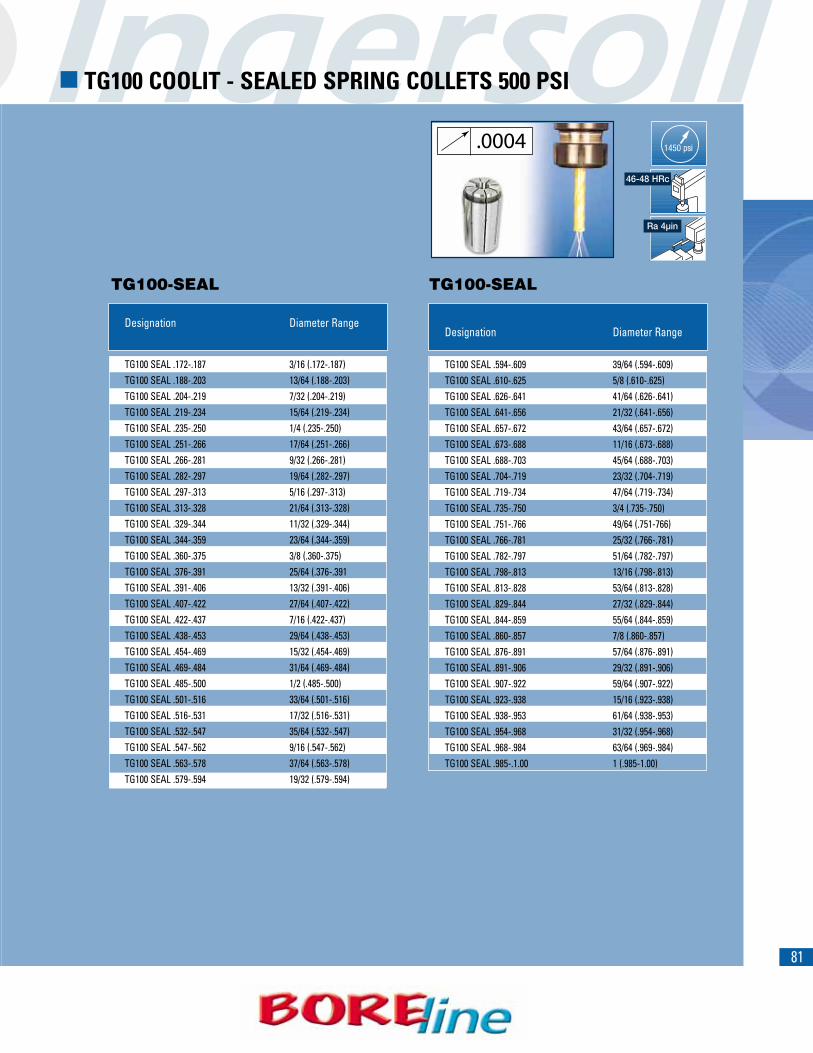
81
� TG100 COOLIT - SEALED SPRING COLLETS 500 PSI
TG100-SEAL TG100-SEAL
ER32, 40-SEAL-JET2Designation Diameter Range
TG100 SEAL .172-.187 3/16 (.172-.187)TG100 SEAL .188-.203 13/64 (.188-.203)TG100 SEAL .204-.219 7/32 (.204-.219)TG100 SEAL .219-.234 15/64 (.219-.234)TG100 SEAL .235-.250 1/4 (.235-.250)TG100 SEAL .251-.266 17/64 (.251-.266)TG100 SEAL .266-.281 9/32 (.266-.281)TG100 SEAL .282-.297 19/64 (.282-.297)TG100 SEAL .297-.313 5/16 (.297-.313)TG100 SEAL .313-.328 21/64 (.313-.328)TG100 SEAL .329-.344 11/32 (.329-.344)TG100 SEAL .344-.359 23/64 (.344-.359)TG100 SEAL .360-.375 3/8 (.360-.375)TG100 SEAL .376-.391 25/64 (.376-.391TG100 SEAL .391-.406 13/32 (.391-.406)TG100 SEAL .407-.422 27/64 (.407-.422)TG100 SEAL .422-.437 7/16 (.422-.437)TG100 SEAL .438-.453 29/64 (.438-.453)TG100 SEAL .454-.469 15/32 (.454-.469)TG100 SEAL .469-.484 31/64 (.469-.484)TG100 SEAL .485-.500 1/2 (.485-.500)TG100 SEAL .501-.516 33/64 (.501-.516)TG100 SEAL .516-.531 17/32 (.516-.531)TG100 SEAL .532-.547 35/64 (.532-.547)TG100 SEAL .547-.562 9/16 (.547-.562)TG100 SEAL .563-.578 37/64 (.563-.578)TG100 SEAL .579-.594 19/32 (.579-.594)
ER32, 40-SEAL-JET2Designation Diameter Range
TG100 SEAL .594-.609 39/64 (.594-.609)TG100 SEAL .610-.625 5/8 (.610-.625)TG100 SEAL .626-.641 41/64 (.626-.641)TG100 SEAL .641-.656 21/32 (.641-.656)TG100 SEAL .657-.672 43/64 (.657-.672)TG100 SEAL .673-.688 11/16 (.673-.688)TG100 SEAL .688-.703 45/64 (.688-.703)TG100 SEAL .704-.719 23/32 (.704-.719)TG100 SEAL .719-.734 47/64 (.719-.734)TG100 SEAL .735-.750 3/4 (.735-.750)TG100 SEAL .751-.766 49/64 (.751-766)TG100 SEAL .766-.781 25/32 (.766-.781)TG100 SEAL .782-.797 51/64 (.782-.797)TG100 SEAL .798-.813 13/16 (.798-.813)TG100 SEAL .813-.828 53/64 (.813-.828)TG100 SEAL .829-.844 27/32 (.829-.844)TG100 SEAL .844-.859 55/64 (.844-.859)TG100 SEAL .860-.857 7/8 (.860-.857)TG100 SEAL .876-.891 57/64 (.876-.891)TG100 SEAL .891-.906 29/32 (.891-.906)TG100 SEAL .907-.922 59/64 (.907-.922)TG100 SEAL .923-.938 15/16 (.923-.938)TG100 SEAL .938-.953 61/64 (.938-.953)TG100 SEAL .954-.968 31/32 (.954-.968)TG100 SEAL .968-.984 63/64 (.969-.984)TG100 SEAL .985-.1.00 1 (.985-1.00)
.0004
Ra 4µin
46-48 HRc
1450 psi

82
� ER SPRING COLLET SETS
� ER COOLIT - SEALED JETS COLLET SETS 1450- PSI
Ra 4µin46-48 HRc
Ra 4µin46-48 HRc
1450 psi
ER32, 40-SEAL-JET2Pcs. Diameter Diameter
Designation Range Range (mm)
SET ER11 SPR 7 AA 7 .022-.278 0.5-7SET ER16 SPR 10 AA 10 .022-.396 0.5-10SET ER20 SPR 12 AA 12 .041-.514 1-13SET ER25 SPR 15 AA 15 .041-.632 1-16SET ER32 SPR 18 AA 18 .080-.789 2-20SET ER40 SPR 23 AA 23 .120-1.025 3-26
ER32, 40-SEAL-JET2Pcs. Diameter Diameter
Designation Range Range (mm)
SET ER16 SEAL 7 7 .120-.396 3-10SET ER20 SEAL 10 10 .120-.514 3-13SET ER25 SEAL 13 13 .120-.632 3-16SET ER32 SEAL 17 17 .120-.789 3-20SET ER40 SEAL 23 23 .120-1.025 3-26
ER32, 40-SEAL-JET2Pcs. Diameter Diameter
Designation Range Range (mm)
SET ER16 SEAL 7 JET2 7 .120-.396 3-10SET ER20 SEAL 10 JET2 10 .120-.514 3-13SET ER25 SEAL 13 JET2 13 .120-.632 3-16SET ER32 SEAL 17 JET2 17 .120-.789 3-20SET ER40 SEAL 23 JET2 23 .120-1.025 3-26
ER32, 40-SEAL-JET2Pcs. Diameter Diameter
Designation Range Range (mm)
SET ER11 SPR 7 7 .022-.278 0.5-7SET ER16 SPR 10 10 .022-.396 0.5-10SET ER20 SPR 12 12 .041-.514 1-13SET ER25 SPR 15 15 .041-.632 1-16SET ER32 SPR 18 18 .080-.789 2-20SET ER40 SPR 23 23 .120-1.025 3-26SET ER50 SPR 12 12 .396-1.338 10-34
AA
SET-ER SPR SPRING COLLETS DIN 6499
SET-ER-SPR-AA SPRING COLLETS DIN 6499 “AA”
SET ER-SEAL COLLETS 6499
SET ER-SEAL-JET2 COLLETS DIN 6499

83
Ra 4µin46-48 HRc
Ra 4µin46-48 HRc
Ra 4µin46-48 HRc
� ER SPRING EMI COLLET SETS DIN 6490
� ER COOLIT - SEALED JET EMI COLLET SETS
(1) EMI-Endmill cutter inch sizes
(1) EMI-Endmill cutter inch sizes
1450 psi
1450 psi
ER32, 40-SEAL-JET2Designation Pcs. Collet Sizes
SET ER16 SPR 5 EMI 5 1/8, 3/16, 1/4, 5/16, 3/8SET ER20 SPR 5 EMI 5 3/16, 1/4 ,5/16, 3/8 ,1/2SET ER25 SPR 6 EMI 6 3/16, 1/4, 5/1,6 3/8, 1/2, 5/8SET ER32 SPR 6 EMI 6 1/4, 3/16, 5/16, 3/8, 1/2, 5/8, 3/4SET ER40 SPR 7 EMI 7 1/4, 3/16, 5/16, 3/8, 1/2, 5/8, 3/4, 1
ER32, 40-SEAL-JET2Designation Pcs. Collet Sizes
SET ER 16 SEAL 5 EMI 5 1/8, 3/16, 1/4, 5/16, 3/8SET ER 20 SEAL 5 EMI 5 1/8, 3/16, 1/4, 5/16, 3/8, 1/2SET ER 25 SEAL 6 EMI 6 1/8, 3/16, 1/4, 5/16, 3/8,1/2, 5/8SET ER 32 SEAL 6 EMI 6 3/16, 1/4, 5/16, 3/8,1/2, 5/8, 3/4SET ER 40 SEAL 7 EMI 7 3/16, 1/4, 5/16, 3/8,1/2, 5/8, 3/4, 1
ER32, 40-SEAL-JET2Set
Designation Pcs. Collet Sizes
SET ER 16 SEAL 5 EMI JET2 5 1/8, 3/16, 1/4, 5/16, 3/8SET ER 20 SEAL 5 EMI JET2 5 1/8, 3/16, 1/4, 5/16, 3/8, 1/2SET ER 25 SEAL 6 EMI JET2 6 1/8, 3/16, 1/4, 5/16, 3/8,1/2, 5/8SET ER 32 SEAL 6 EMI JET2 6 3/16, 1/4, 5/16, 3/8,1/2, 5/8, 3/4SET ER 40 SEAL 7 EMI JET2 7 3/16, 1/4, 5/16, 3/8,1/2, 5/8, 3/4, 1
SET ER SPR-EMI (1)
SET-ER SEAL-EMI(1)
SET-ER SEAL-EMI JET2

� GRADE DESCRIPTIONSPAGE 86
� CARBIDE SELECTION GUIDEPAGE 87
� WORKPIECE MATERIAL DATAPAGE 88
� GUIDELINESPAGE 91
� DR SOLID CARBIDE GUIDELINESPAGE 94
� GUIDELINESPAGE 95

� CHAMFER RINGSPAGE 100
� SLIP-FITPAGE 102
� GUIDELINESPAGE 103
� GUIDELINESPAGE 109
� GUIDELINESPAGE 111

1286
� STANDARD GRADE DESCRIPTIONSU
NC
(Unc
oate
d)CV
D (C
hem
ical
Vapo
r Dep
ositi
on)
PVD
(Phy
sica
lVa
por D
epos
ition
)
Grade Industry ISO WorkpieceNumber Class Rating Coating Materials
IN30M C-1/C-2 K20-K50None
Cast iron, aluminum, non-ferrous materials,M20-M40 high-temp alloys
IN40P C-5/C-6 P20-P35 None Steels
IN6515 C-1/C-3 K15-K35 MT-CVD Cast iron, steelsC-5/C-7 P20-P30 Al2O3
C-2/C-1K20-K50
MT-CVD ,IN6530 M25-M40 Cast iron, steels, stainless, high-temp alloysC-5/C-6 P25-P45
Al2O3
IN1030 C-1/C-2K20-K30 PVD Cast iron, aluminum, stainless, titanium
M20-M40 TiCN
IN1040 C-5/C-7 P20-P40 PVD Steels, stainlessTiCN
IN1505 C-1/C-7 P10-P30 Cast iron, steels, stainless, high-temp alloysM10-M30 TiCN-TiN
IN1530 C-1/C-5K25-K40 PVD
Steels, stainless, titanium, high-temp alloysM30-M40 TiCN-TiN
IN2005 C-1/C-8 K50-P01 PVD Cast iron, steels, stainless, high-temp alloysTiAlN
IN2030 C-1/C-5 K25-K40 Cast iron, steels, stainless, high-temp alloysM30-M40 TiAIN
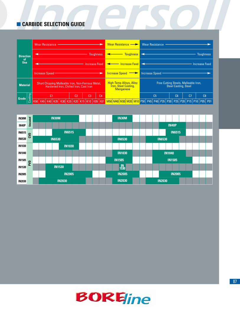
1387
� CARBIDE SELECTION GUIDE
Grade
Material
Directionof
Use
Wear Resistance
Toughness Toughness Toughness
Wear ResistanceWear Resistance
Increase Speed
Increase Feed Increase Feed Increase Feed
Increase Speed Increase Speed
C1 C2 C3 C4
K50 K45 K40 K35 K30 K25 K20 K15 K10 K05 K01
Short Chipping Malleable Iron, Non-Ferrous Metal,Hardened Iron, Chilled Iron, Cast Iron
Free Cutting Steels, Malleable Iron, Steel Casting, Steel
C5 C6 C7 C8
P50 P45 P40 P35 P30 P25 P20 P15 P10 P05 P01
High-Temp Alloys, AlloyIron, Steel Casting,
Manganese
M50 M40 M30 M20 M10Coat
ing
IN30M
IN40P
IN6515
IN6530
IN1030
IN1040
IN1505
IN1530
IN2005
IN2030
IN40P
IN6515 IN6515
IN6530
IN1505
IN6530
IN1030
IN1505
IN1040
IN1530IN1530
IN1030
IN30M
IN6530
IN30M
PVD
C
VD
U
ncoa
ted
IN2005
IN2030
IN2005
IN2030 IN2030
IN2005
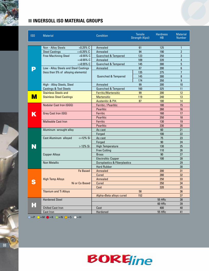
88
(CONT.)ISO Material Condition Tensile Hardness Material
Strength (Kpsi) HB Number
Non - Alloy Steels <0.25% C Annealed 61 125 1 Steel Castings =>0.25% C Annealed 94 190 2Free Machining Steel <0.55% C Quenched & Tempered 123 250 3
=>0.55% C Annealed 109 220 4=>0.55% C Quenched & Tempered 145 300 5
Low - Alloy Steels and Steel Castings Annealed 87 200 6(less than 5% of alloying elements) 135 275 7
Quenched & Tempered 145 300 8174 350 9
High - Alloy Steels, Steel Annealed 99 200 10Castings & Tool Steels Quenched & Tempered 160 325 11Stainless Steels and Ferritic/Martensitic 99 200 12Stainless Steel Castings Martensitic 119 240 13
Austenitic & P.H. 87 180 14Nodular Cast Iron (GGG) Ferritic / Pearlitic 180 15
Pearlitic 260 16Grey Cast Iron (GG) Ferritic 160 17
Pearlitic 250 18Malleable Cast Iron Ferritic 130 19
Pearlitic 230 20Aluminum wrought alloy As cast 60 21
Forged 100 22Cast Aluminum alloyed <=12% Si As cast 75 23
Forged 90 24> 12% Si High Temperature 130 25
Free Cutting 110 26Copper Alloys Brass 90 27
Electrolitic Copper 100 28Non Metallic Duroplastics & Fiberplastics 29
Hard Rubber 30Fe Based Annealed 200 31
Cured 280 32High Temp Alloys Annealed 250 33
Ni or Co Based Cured 350 34Cast 320 35
Titanium and Ti Alloys 58 36Alpha+Beta alloys cured 152 37
Hardened Steel 55 HRc 3860 HRc 39
Chilled Cast Iron Cast 400 40Cast Iron Hardened 55 HRc 41
P
M
K
N
S
H
� INGERSOLL ISO MATERIAL GROUPS
= P =M = K = N = S = H
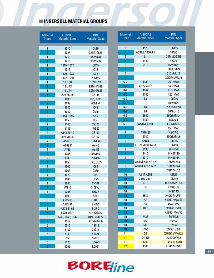
89
Material AISI/SAE DINGroup Material Spec Material Spec
1 1010 Ck101 1025 C25E, Ck251 1213 9SMn281 1215 9SMn361 1015, 1017 CK151 1016 C151 1020, 1023 C221 1022, 1518 20Mn51 11 L 08 10SPb201 12 L 13 9SMnPb281 12 L 14 9SMnPb361 A27 65-35 GS-452 1035 C35, Cf352 1039 40Mn42 1040 C402 1042 Ck452 1043, 1045 C452 1050 Cf532 1140 35S202 1146 45S202 A148 80 40 GS-602 A27 70-36 GS-522 A537 1 19Mn62 A662 C Ast452 A738 Ast522 1335 36Mn52 1330 28Mn64 1055 C55, Ck554 1060 C604 1064 Ck604 1070 Ck674 1080 Ck754 1095 Ck1014 W110 C105W14 9255 55Si76 1006 St366 A515 65 H16 A573 81 St44-36 A573 81 65 St37-36 8620, 8617 21NiCrMo26 8740, 8640, 8742 40NiCrMo226 4317 17CrNiMo66 5015 15Cr36 5132 34Cr46 5140 41Cr46 5155 55Cr36 5120 St52-36 9262 1.0961
Material AISI/SAE DINGroup Material Spec Material Spec
6 4520 16Mo56 ASTM A350LF5 14Ni66 L1 34MoCrS4G6 5140 42Cr46 5115 16MnCr56 14MoV6 36 31CeMo126 39CrMoV13 9
6-7 4130 25CrMo46-7 4135, 4137 34CrMo46-7 4142 41CrMo46-7 4140 42CrMo46-9 L3 100Cr66-9 105WCr66-9 L6 55NiCrMoV66-9 L6 50NiCr136-9 9840 36CrNiMo46-9 6150 50CrV46-9 ASTM A290 41CrAlMo77 15CrMo57 A570-36 RSt37-27 4340 35CrNiMo69 52100 100Cr69 ASTM A204 Gr. A 15Mo39 3135 36NiCr69 3415 14NilCr109 3310 14NilCr149 ASTM A182 F-12 13CrMo449 ASTM A387 12-2 16CrMo449 32CrMo1210 ASM A353 X8Ni910 2515, 2517 12Ni1910 9310 14NiCrMo13-410 D3 X210Cr1210 X42Cr1310 H13 X40CrMoV5110 A2 X100CrMoV5110 S1 45WCrV710 H21 X30WCrV9310 X165CrMoV1210 M35 S6/5/2/510 M2 S6/5/210 M7 S2/9/210 HW3 X45CrSi9311 D2 X155CrVMo12111 D4, D6 X210CrW1211 630 1.4542/1.454812 430F X12CrMoS17
� INGERSOLL MATERIAL GROUPS
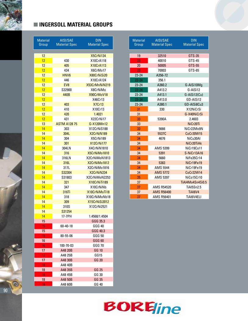
90
Material AISI/SAE DINGroup Material Spec Material Spec
12 X5CrNi13412 430 X10CrA11812 405 X10CrA11312 434 X6CrMo1712 HNV6 X80CrNiSi2012 446 X10CrA12412 EV8 X53CrMnNiN21912 S32900 X8CrNiMo12 440B X90CrMoV1812 X46Cr1312 403 X7Cr1312 410 X10Cr1312 420 1.402112 431 X22CrNi1713 ASTM A128 75 G-X120Mn1214 303 X12CrNiS18814 304L X2CrNiN18914 304 X5CrNi18914 301 X12CrNi17714 304LN X4CrNiN181014 316 X5CrNiMo181014 316LN X2CrNiMoN181314 316L X2CrNiMo181214 317L X2CrNiMo181614 S32304 X2CrNiN23414 S31803 X2CrNiMoN225314 321 X10CrNiTi18914 347 X10CrNiNb14 316Ti X10CrNiMoTi1814 318 X10CrNiMoNb1814 309 X15CrNiSi201214 310S X12CrNi252114 S3125414 17-7PH 1.4568/1.450415 GGG 35.315 60-40-18 GGG 4015 GGG 40.315 80-55-06 GGG 5016 GGG 6016 100-70-03 GGG 7017 A48 20B GG 1017 A48 25B GG1517 A48 30B GG 2018 A48 40B18 A48 35B GG 2518 A48 45B GG 3018 A48 50B GG 3518 A48 60B GG 40
Material AISI/SAE DINGroup Material Spec Material Spec
19 32510 GTS-3520 40010 GTS-4520 50005 GTS-5520 70003 GTS-65
23-24 A356-7223-24 356.123-24 A360.2 G-AlSi10Mg23-24 A413.2 G-AlSi1223-24 A413.1 G-AlSi12(Cu)23-24 A413.0 GD-AlSi1223-24 A380.1 GD-AlSi8Cu3
31 330 X12NiCrSi31 G-X40NiCrSi33 5390A 2.460333 NiCr20Ti33 5666 NiCr22Mo9N34 5537C CoCr20W1534 4676 NiCu30Al34 NiCr20TiAk34 AMS 5399 NiCr19Co1134 5391 S-NiCr13A1634 5660 NiFe35Cr1434 5383 NiCr19Fe1934 AMS 5544 NiCr19Fe1934 AMS 5772 CoCr22W1435 AMS 5397 NiCo15Cr1037 TiAl4Mo4Sn4Si0.537 AMS R54520 TiAl5Sn2.537 AMS R56400 TiAl6V437 AMS R56401 TiAl6V4ELI
� INGERSOLL MATERIAL GROUPS

91
1 450 - 550 .001" - .003"2 450 - 550 .001" - .003"3 450 - 550 .001" - .003"4 450 - 550 .001" - .003"5 450 - 550 .001" - .003"6 450 - 550 .001" - .003"7 450 - 550 .001" - .003"8 450 - 550 .001" - .003"9 450 - 550 .001" - .003"10 450 - 550 .001" - .003"11 450 - 550 .001" - .003"12 400 - 500 .001" - .003"13 300 - 400 .001" - .003"14 400 - 500 .001" - .003"15 300 - 400 .002" - .004"16 300 - 400 .002" - .004"17 450 - 550 .002" - .004"18 450 - 550 .002" - .004"19 450 - 550 .002" - .004"20 450 - 550 .002" - .004"21 1500 - 3000 .002" - .004"22 1500 - 3000 .002" - .004"23 1500 - 3000 .002" - .004"24 1500 - 3000 .002" - .004"25 1500 - 3000 .002" - .004"26 1500 - 3000 .002" - .004"27 1500 - 3000 .002" - .004"28 1500 - 3000 .002" - .004"293031 100 - 200 .001" - .003"32 100 - 200 .001" - .003"33 100 - 200 .001" - .003"34 100 - 200 .001" - .003"35 100 - 200 .001" - .003"36 130 - 230 .001" - .003"37 130 - 230 .001" - .003"38 50 - 100 .001" - .003"39 50 - 100 .001" - .003"40 50 - 100 .001" - .003"41 50 - 100 .001" - .003"
P
M
K
N
S
H
Material Cutting Feed (in./rev.)ISO Number Speed ø.189-ø.292
(SFM)
1 260 - 430 .006" - .010"2 260 - 430 .006" - .010"3 230 - 390 .006" - .010"4 230 - 390 .006" - .010"5 230 - 390 .006" - .010"6 130 - 430 .006" - .010"7 130 - 430 .006" - .010"8 130 - 430 .006" - .010"9 130 - 430 .006" - .010"10 130 - 260 .005" - .008"11 130 - 260 .005" - .008"12 70 - 160 .004" - .006"13 70 - 160 .004" - .006"14 70 - 160 .004" - .006"15 260 - 460 .010" - .014"16 260 - 460 .010" - .014"17 300 - 590 .010" - .014"18 300 - 590 .010" - .014"19 300 - 590 .010" - .014"20 300 - 590 .010" - .014"21 260 - 520 .010" - .014"22 260 - 520 .010" - .014"23 260 - 520 .010" - .014"24 260 - 520 .010" - .014"25 260 - 520 .010" - .014"26 260 - 520 .010" - .014"27 260 - 520 .010" - .014"28 260 - 520 .010" - .014"293031 70 - 160 .003" - .005"32 70 - 160 .003" - .005"33 70 - 160 .003" - .005"34 70 - 160 .003" - .005"35 70 - 160 .003" - .005"36 70 - 160 .004" - .006"37 70 - 160 .004" - .006"38 70 - 160 .004" - .006"39 70 - 160 .004" - .006"40 70 - 160 .004" - .006"41 70 - 160 .004" - .006"
P
M
K
N
S
H
Material Cutting Feed (in./rev.)ISO Number Speed ø.189-ø.292
(SFM)
� OPERATING GUIDELINES- SERIES FAK AND SERIES Y
SERIES “FAK” DRILL SERIES “Y” (SPOT IN) DRILL
= P =M = K = N = S = H

92
*Z-axis DOC is measured to theoretical sharp corner.
� DIncluded Spot Diameter
Angle .060 .090 .120 .150 .210 .270 .330 .390 .480 .570 .660 .750 .840
82° .035 .052 .069 .086 .121 .155 .190 .224 .276 .328 .380 .431 -90° .030 .045 .060 .075 .105 .135 .165 .195 .240 .285 .330 .375 .420118° .018 .027 .036 .045 .063 .081 .099 .117 .144 .171 .198 - -135° .012 .019 .025 .031 .043 .056 .068 .081 .099 .118 .137 - -144° .010 .015 .019 .024 .034 .044 .054 .063 .078 .093 .107 - -
Z-Axis DOC to Spot Diameter Chart (FAK)
Insert loading is easyand fast. Simply
insert the drill pointinto the special
dovetail bayonetpocket. Then turn it
to the locked positionusing the properclamping wrench
provided with eachdrill body.
*Z-axis DOC is measured to theoretical sharp corner.
Z-Axis DOC to Spot Diameter Chart (SPOT IN)D1 � D2
Cutter Dia. Included Spot Diameterinch mm Angle .060 .090 .120 .150 .200 .250 .310 .380 .470 .500 .560 .630
.630 16,0 90° .030 .045 .060 .075 .100 .125 .155 .190 .235 .250 .280 .315
.630 16,0 140° .011 .016 .022 .027 .036 .045 .056 .069 .086 .091 .102 .115
.472 12,0 90° .030 .045 .060 .075 .100 .125 .155 .190 .235 - - -
.472 12,0 140° .011 .016 .022 .027 .036 .045 .056 .069 .086 - - -
Insert Loading:
� GUIDELINES- SERIES FAK AND SERIES Y

93
SPOTTING DRILL RECOMMENDATIONS FOR SOLID CARBIDE AND QWIK TWIST DRILLS
Spotting Drill Point Angle
Drill Point Angle
Spotting Drill Point Angle
Drill Point Angle
ACCEPTABLESpotting drill angle is the same as the drill point angle.• Tool loading problems can occur due to immediate
full engagement.• Chatter may be a problem.• Reduced feed at entry recommended.• Good drill centering.
BESTSpotting drill angle is greater than the drill point angle.• First contact is at the drill point.• Best drill centering possibility.• Drill loading increases with penetration.
Spotting Drill Point Angle
Drill Point Angle
NOT RECOMMENDED WITH CARBIDESpotting drill angle is less than the drill point angle.• Point contact along cutting lips or corner - drill point
should contact spotted hole first..• Chipping likely in these areas.
� SPOTTING DRILL RECOMMENDATIONS
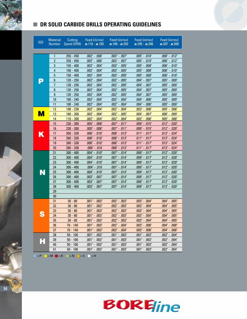
94
(CONT.)
� DR SOLID CARBIDE DRILLS OPERATING GUIDELINES
P
M
K
N
S
H
Material Cutting Feed (in/rev) Feed (in/rev) Feed (in/rev) Feed (in/rev)ISO Number Speed (SFM) ø.118 - ø.185 ø.189 - ø.292 ø.295 - ø.396 ø.397 - ø.500
1 250 - 450 .002" - .006" .003" - .007" .005" - .010" .006" - .012"2 250 - 450 .002" - .006" .003" - .007" .005" - .010" .006" - .012"3 150 - 400 .002" - .004" .003" - .005" .005" - .008" .006" - .010"4 150 - 400 .002" - .004" .003" - .005" .005" - .008" .006" - .010"5 150 - 400 .002" - .004" .003" - .005" .005" - .008" .006" - .010"6 120 - 250 .002" - .004" .002" - .005" .004" - .007" .005" - .009"7 120 - 250 .002" - .004" .002" - .005" .004" - .007" .005" - .009"8 120 - 250 .002" - .004" .002" - .005" .004" - .007" .005" - .009"9 120 - 250 .002" - .004" .002" - .005" .004" - .007" .005" - .009"10 100 - 240 .002" - .004" .002" - .004" .004" - .006" .005" - .009"11 100 - 240 .002" - .004" .002" - .004" .004" - .006" .005" - .009"12 190 - 230 .002" - .004" .002" - .004" .003" - .006" .005" - .008"13 160 - 200 .002" - .004" .002" - .005" .004" - .007" .006" - .009"14 110 - 200 .002" - .004" .002" - .004" .003" - .006" .005" - .008"15 230 - 300 .005" - .008" .007" - .011" .009" - .015" .012" - .020"16 230 - 300 .005" - .008" .007" - .011" .009" - .015" .012" - .020"17 260 - 330 .006" - .010" .008" - .013" .011" - .017" .013" - .024"18 260 - 330 .006" - .010" .008" - .013" .011" - .017" .013" - .024"19 260 - 330 .006" - .010" .008" - .013" .011" - .017" .013" - .024"20 260 - 330 .006" - .010 .008" - .013" .011" - .017" .013" - .024"21 300 - 400 .004" - .010" .007" - .014" .009" - .017" .012" - .020"22 300 - 400 .004" - .010" .007" - .014" .009" - .017" .012" - .020"23 300 - 400 .004" - .010" .007" - .014" .009" - .017" .012" - .020"24 300 - 400 .004" - .010 .007" - .014" .009" - .017" .012" - .020"25 300 - 400 .004" - .010" .007" - .014" .009" - .017" .012" - .020"26 300 - 400 .003" - .007" .007" - .014" .009" - .017" .012" - .020"27 300 - 400 .003" - .007" .007" - .014" .009" - .017" .012" - .020"28 300 - 400 .003" - .007" .007" - .014" .009" - .017" .012" - .020"293031 30 - 80 .001" - .003" .002" - .003" .003" - .004" .004" - .005"32 30 - 80 .001" - .003" .002" - .003" .003" - .004" .004" - .005"33 30 - 80 .001" - .003" .002" - .003" .003" - .004" .004" - .005"34 30 - 80 .001" - .003" .002" - .003" .003" - .004" .004" - .005"35 30 - 80 .001" - .003" .002" - .003" .003" - .004" .004" - .005"36 70 - 140 .001" - .003" .002" - .004" .003" - .006" .004" - .008"37 70 - 140 .001" - .003" .002" - .004" .003" - .006" .004" - .008"38 50 - 100 .001" - .002" .001" - .003" .001" - .003" .002" - .004"39 50 - 100 .001" - .002" .001" - .003" .001" - .003" .002" - .004"40 50 - 100 .001" - .002" .001" - .003" .001" - .003" .002" - .004"41 50 - 100 .001" - .002" .001" - .003" .001" - .003" .002" - .004"
= P =M = K = N = S = H
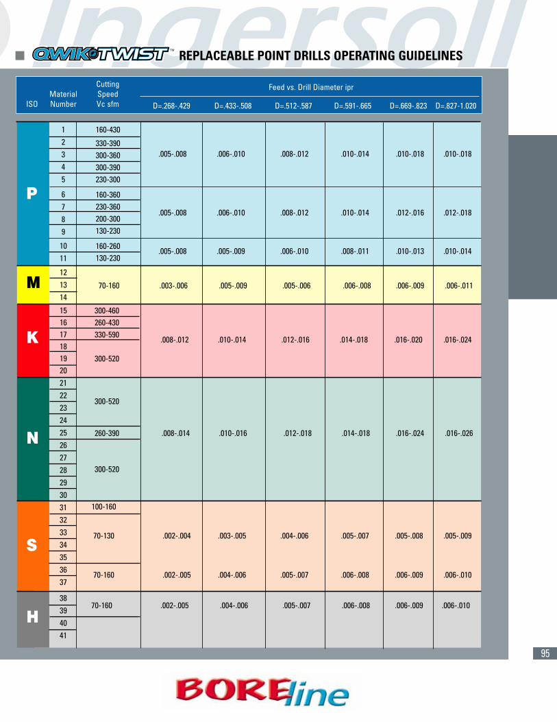
95
D=.268-.429 D=.433-.508 D=.512-.587 D=.591-.665 D=.669-.823 D=.827-1.020
160-430
330-390300-360 .005-.008 .006-.010 .008-.012 .010-.014 .010-.018 .010-.018
300-390230-300
160-360230-360
.005-.008 .006-.010 .008-.012 .010-.014 .012-.016 .012-.018200-300130-230
160-260 .005-.008 .005-.009 .006-.010 .008-.011 .010-.013 .010-.014130-230
300-460260-430330-590 .008-.012 .010-.014 .012-.016 .014-.018 .016-.020 .016-.024
300-520
70-160 .003-.006 .005-.009 .005-.006 .006-.008 .006-.009 .006-.011
300-520
260-390 .008-.014 .010-.016 .012-.018 .014-.018 .016-.024 .016-.026
300-520
100-160
70-130 .002-.004 .003-.005 .004-.006 .005-.007 .005-.008 .005-.009
70-160 .002-.005 .004-.006 .005-.007 .006-.008 .006-.009 .006-.010
70-160 .002-.005 .004-.006 .005-.007 .006-.008 .006-.009 .006-.010
Cutting SpeedVc sfm
MaterialNumberISO
Feed vs. Drill Diameter ipr
� REPLACEABLE POINT DRILLS OPERATING GUIDELINES
P
K
M
N
S
H
12345
6789
1011
121314
1516171819202122232425262728293031323334353637
38394041

96
� REPLACEABLE POINT DRILLS
DRILL POINT REPLACEMENT INDICATIONS
Fig. 1: Wear Limit Fig. 2: Power Restriction
.008"-.012"
P Px1.25(1) (2)
Spindle loadmeter
(1) New Drill Point(2) Worn Out Drill Point
Fig. 3: Diameter Change Fig. 4: Surface Finish Decline Fig. 5: Noise or vibration drastically increases
1. Limit cutting edge wear to .008” to .012”.(see Fig. 1)
2. Power consumption exceeds 125% of normal. (see Fig. 2)
3. Drilled hole diameter variation.(see Fig. 3)
4. Deterioration of surface finish of the drilled hole.(see Fig. 4)
5. Significant increase in noise or vibration. (see Fig. 5)
For proper chip evacuation, the coolantmust flow through the tool. If the machineis not equipped with coolant through thespindle, we recommend using a coolantinducer. External coolant supply can beused if the hole depth is less than 1xD andreduced cutting parameters are applied.
Coolant MixRecommended coolant concentration is6% to 8%. When drilling stainless andhigh strength steels, a 10% concentrationis recommended.
Dry DrillingIt is possible to drill without coolant incast iron. oil mist through the drill isrequired (2xD max hole depth).
RECOMMENDED COOLANT PRESSURE AND FLOW RATE

97
COOLANT
Through the toolCoolant
No Coolant
External Coolant
Acceptable up to Depth=2xDiam.
External Coolant
Wrong Coolant Direction
Most Recommended Not Recommended
In stationary drill applications both through the tool and external coolant is recommended.
DRILLING LIMITATIONS
Angular or Irregular Surfaces (Maximum 6˚ angle) Interrupted or Partial Holes
� REPLACEABLE POINT DRILLS
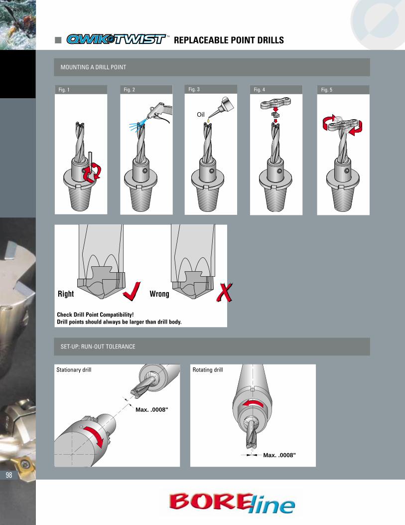
98
MOUNTING A DRILL POINT
Fig. 1
Check Drill Point Compatibility!Drill points should always be larger than drill body.
Fig. 2 Fig. 4 Fig. 5
SET-UP: RUN-OUT TOLERANCE
Max. .0008"
Stationary drill
Max. .0008"
Rotating drill
� REPLACEABLE POINT DRILLS
Fig. 3
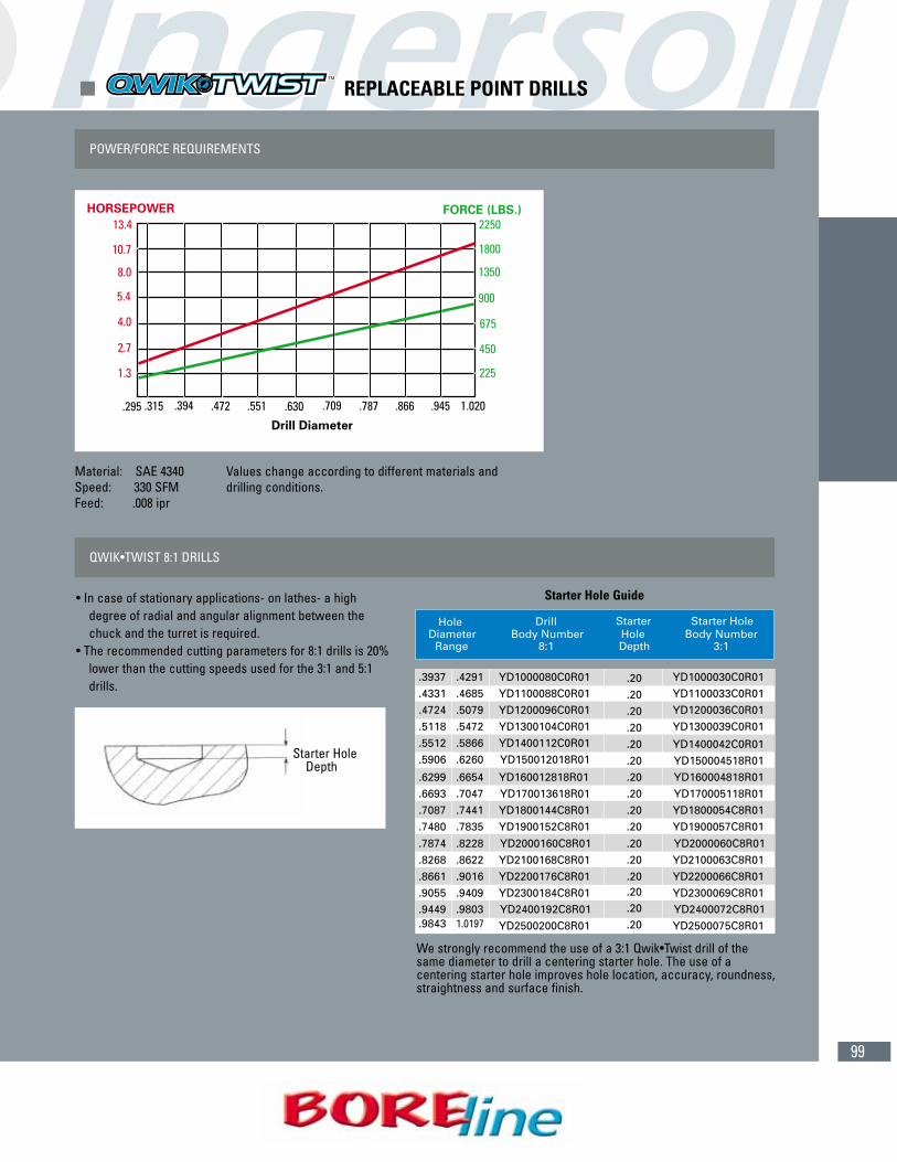
99
POWER/FORCE REQUIREMENTS
Material: SAE 4340 Values change according to different materials andSpeed: 330 SFM drilling conditions.Feed: .008 ipr
QWIK•TWIST 8:1 DRILLS
• In case of stationary applications- on lathes- a high degree of radial and angular alignment between the chuck and the turret is required.
• The recommended cutting parameters for 8:1 drills is 20% lower than the cutting speeds used for the 3:1 and 5:1 drills.
Starter Hole Guide
We strongly recommend the use of a 3:1 Qwik•Twist drill of thesame diameter to drill a centering starter hole. The use of a centering starter hole improves hole location, accuracy, roundness,straightness and surface finish.
Starter Hole Depth
� REPLACEABLE POINT DRILLS
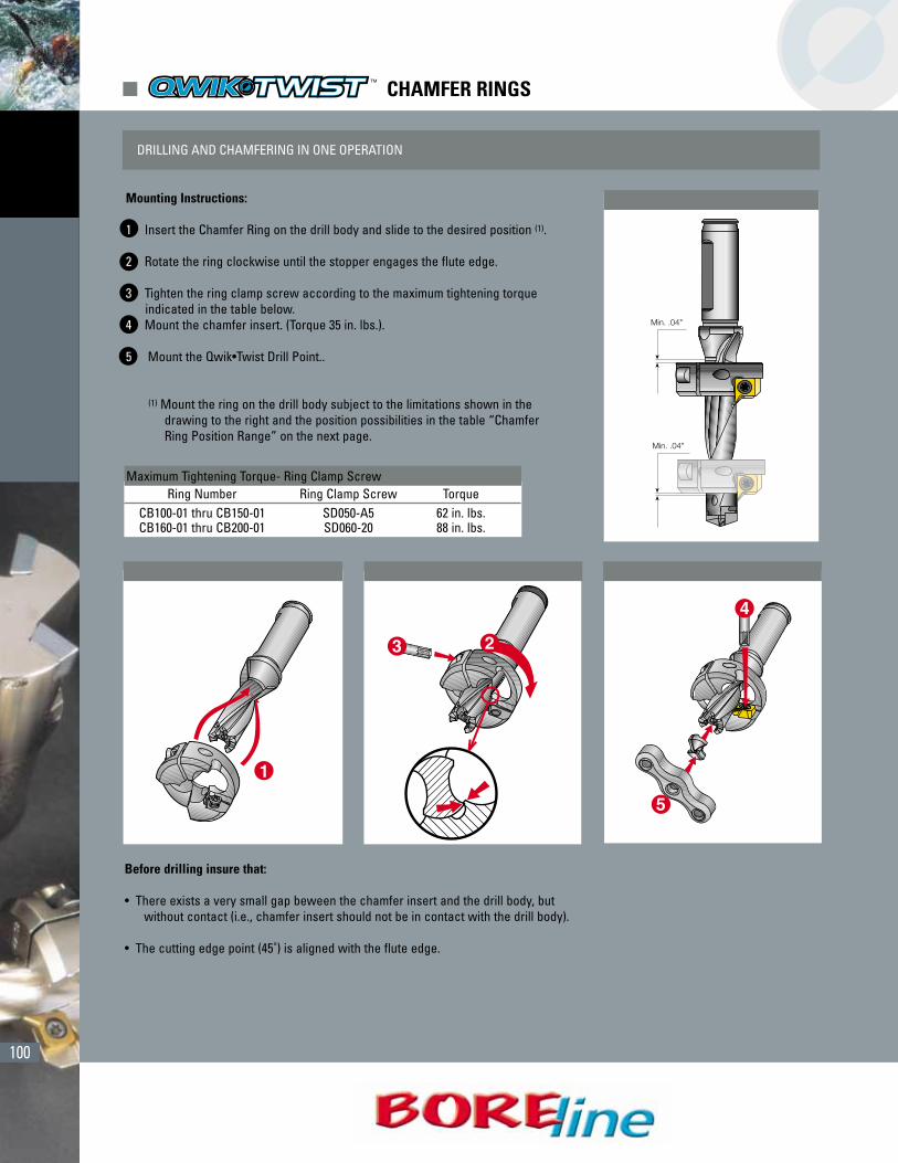
100
� CHAMFER RINGS
DRILLING AND CHAMFERING IN ONE OPERATION
Mounting Instructions:
1 Insert the Chamfer Ring on the drill body and slide to the desired position (1).
2 Rotate the ring clockwise until the stopper engages the flute edge.
3 Tighten the ring clamp screw according to the maximum tightening torque indicated in the table below.
4 Mount the chamfer insert. (Torque 35 in. lbs.).
5 Mount the Qwik•Twist Drill Point..
(1) Mount the ring on the drill body subject to the limitations shown in the drawing to the right and the position possibilities in the table “Chamfer Ring Position Range” on the next page.
Before drilling insure that:
• There exists a very small gap beween the chamfer insert and the drill body, butwithout contact (i.e., chamfer insert should not be in contact with the drill body).
• The cutting edge point (45˚) is aligned with the flute edge.
Maximum Tightening Torque- Ring Clamp ScrewRing Number Ring Clamp Screw Torque
CB100-01 thru CB150-01 SD050-A5 62 in. lbs.CB160-01 thru CB200-01 SD060-20 88 in. lbs.
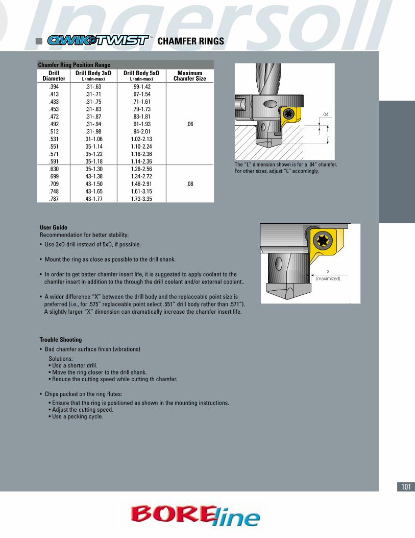
101
User GuideRecommendation for better stability:
• Use 3xD drill instead of 5xD, if possible.
• Mount the ring as close as possible to the drill shank.
• In order to get better chamfer insert life, it is suggested to apply coolant to the chamfer insert in addition to the through the drill coolant and/or external coolant..
• A wider difference “X” between the drill body and the replaceable point size is preferred (i.e., for .575” replaceable point select .551” drill body rather than .571”). A slightly larger “X” dimension can dramatically increase the chamfer insert life.
Trouble Shooting
• Bad chamfer surface finish (vibrations)
Solutions:• Use a shorter drill.• Move the ring closer to the drill shank.• Reduce the cutting speed while cutting th chamfer.
• Chips packed on the ring flutes:• Ensure that the ring is positioned as shown in the mounting instructions.• Adjust the cutting speed.• Use a pecking cycle.
Chamfer Ring Position RangeDrill Drill Body 3xD Drill Body 5xD Maximum
Diameter L (min-max) L (min-max) Chamfer Size.394 .31-.63 .59-1.42.413 .31-.71 .67-1.54.433 .31-.75 .71-1.61.453 .31-.83 .79-1.73.472 .31-.87 .83-1.81.492 .31-.94 .91-1.93 .06.512 .31-.98 .94-2.01.531 .31-1.06 1.02-2.13.551 .35-1.14 1.10-2.24.571 .35-1.22 1.18-2.36.591 .35-1.18 1.14-2.36.630 .35-1.30 1.26-2.56.699 .43-1.38 1.34-2.72.709 .43-1.50 1.46-2.91 .08.748 .43-1.65 1.61-3.15.787 .43-1.77 1.73-3.35
The “L” dimension shown is for a .04” chamfer.For other sizes, adjust “L” accordingly.
� CHAMFER RINGS

102
Remove Chamfer inserts.Loosen the side lock screw and remove the Slip Fit Drill.Adjust the rear adjusting screw with a flat point screw driver.Insert Slip Fit Drill and slightly tighten the side lock screw.Re-install Chamfer Inserts as per Initial Set-up Instructions #2. Tighten side lock screw.
� CHAMFER SHANK / SLIP FIT DRILL SET-UP & ADJUSTMENT
� CHAMFER SHANK / SLIP FIT DRILL INITIAL SET-UP
� DRILL DEPTH ADJUSTMENT ADJUSTMENT
� CONSTRUCTION
Unscrew the Chamfer Shank side lock screw, the chamfer insert screws, and remove inserts. Insert the proper Slip Fit Drill into the Chamfer Shank and position it against the rear adjusting screw. Slightly tighten the side lock screw for initial tension with the Slip FitDrill.In order to achieve symmetrical positioning of the chamfering inserts and to avoid edge damage, tighten the insert screws graduallyand alternately from side to side insuring the inserts are tightly clamped against the side walls of the peripheral guiding surfaces.Tighten the side lock screw.Install the proper size Qwik Twist Drill point on the Slip Fit Drill.
1
1
2
2
3
12
3
4
5
3
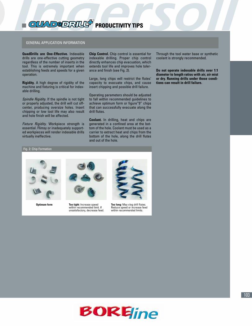
103
� PRODUCTIVITY TIPS
QuadDrills are One-Effective. Indexabledrills are one-effective cutting geometryregardless of the number of inserts in thetool. This is extremely important whenestablishing feeds and speeds for a givenoperation.
Rigidity. A high degree of rigidity of themachine and fixturing is critical for index-able drilling.
Spindle Rigidity. If the spindle is not tightor properly adjusted, the drill will cut off-center, producing oversize holes. Insertchipping or low tool life may also resultand hole finish will be affected.
Fixture Rigidity. Workpiece strength isessential. Flimsy or inadequately support-ed workpieces will render indexable drillsvirtually ineffective.
Chip Control. Chip control is essential forindexable drilling. Proper chip controldirectly enhances chip evacuation, whichextends tool life and improves hole toler-ance and finish (see Fig. 2).
Large, long chips will restrict the flutes’capacity to evacuate chips, and causeinsert chipping and possible drill failure.
Operating parameters should be adjustedto fall within recommended guidelines toachieve optimum form or figure”9” chipsthat can successfully evacuate along thedrill flutes.
Coolant. In drilling, heat and chips aregenerated in a confined area at the bot-tom of the hole. Coolant must be used as acarrier to extract heat and chips from thebottom of the hole, along the drill flutesand out of the hole.
Through the tool water base or syntheticcoolant is strongly recommended.
Do not operate indexable drills over 1:1diameter to length ratios with air, air mistor dry. Running drills under those condi-tions can result in drill failure.
GENERAL APPLICATION INFORMATION
Optimum form Too tight: Increase speedwithin recommended limit. Ifunsatisfactory, decrease feed.
Too long: May clog drill flutes.Reduce speed or increase feedwithin recommended limits.
Fig. 2: Chip Formation
� PRODUCTIVITY TIPS

104
(CONT.)Material Cutting Feed (in/rev) Feed (in/rev) Feed (in/rev) Feed (in/rev) Feed (in/rev)
ISO Number Speed (SFM) ø.500 - ø.594 ø.625 - ø.813 ø.843 - ø1.063 ø1.094 - ø1.312 ø1.343 - ø1.625
1 800 - 1000 .002" - .004" .0025" - .004" .0025" - .005" .003" - .005" .003" - .006"2 800 - 1000 .002" - .004" .0025" - .004" .0025" - .005" .003" - .005" .003" - .006"3 500 - 800 .002" - .004" .003" - .006" .004" - .007" .005" - .0085" .005" - .0095"4 800 - 1000 .002" - .004" .003" - .006" .004" - .007" .005" - .0085" .005" - .0095"5 600 - 800 .002" - .004" .003" - .006" .004" - .007" .005" - .0085" .005" - .0095"6 500 - 800 .002" - .004" .003" - .0055" .004" - .007" .005" - .0085" .005" - .009"7 400 - 700 .002" - .005" .003" - .006" .004" - .007" .005" - .008" .006" - .009"8 400 - 600 .002" - .005" .003" - .006" .004" - .007" .005" - .008" .006" - .009"9 300 - 550 .002" - .005" .003" - .006" .004" - .007" .005" - .008" .006" - .009"10 400 - 600 .002" - .005" .003" - .006" .004" - .007" .005" - .008" .006" - .009"11 400 - 550 .002" - .005" .003" - .006" .004" - .008" .005" - .009" .006" - .0095"12 550 - 800 .002" - .004" .003" - .006" .003" - .006" .0035" - .0065" .004" - .007"13 500 - 700 .002" - .004" .003" - .006" .003" - .006" .0035" - .0065" .004" - .007"14 500 - 700 .002" - .004" .003" - .006" .003" - .006" .0035" - .0065" .004" - .007"15 500 - 800 .002" - .004" .003" - .0065" .005" - .008" .006" - .010" .006" - .011"16 500 - 800 .002" - .004" .003" - .0065" .005" - .008" .006" - .010" .006" - .011"17 600 - 800 .002" - .004" .003" - .0065" .005" - .008" .006" - .010" .006" - .011"18 600 - 800 .002" - .004" .003" - .0065" .005" - .008" .006" - .010" .006" - .011"19 600 - 800 .002" - .004" .003" - .0065" .005" - .008" .006" - .010" .006" - .011"20 500 - 700 .002" - .004" .003" - .0065" .005" - .008" .006" - .010" .006" - .011"21 1300 - 2000 .002" - .005" .003" - .006" .004" - .008" .005" - .009" .0055" - .009"22 1000 - 1300 .002" - .005" .003" - .006" .004" - .008" .005" - .009" .0055" - .009"23 1300 - 2000 .002" - .005" .003" - .006" .004" - .008" .005" - .009" .0055" - .009"24 1000 - 1300 .002" - .005" .003" - .006" .004" - .008" .005" - .009" .0055" - .009"25 1000 - 1300 .002" - .005" .003" - .006" .004" - .008" .005" - .009" .0055" - .009"26 800 - 1000 .002" - .005" .003" - .006" .004" - .008" .005" - .009" .0055" - .009"27 750 - 900 .002" - .005" .003" - .006" .004" - .008" .005" - .009" .0055" - .009"28 800 - 1000 .002" - .005" .003" - .006" .004" - .008" .005" - .009" .0055" - .009"293031 100 - 250 .002" - .004" .0025" - .0055" .003" - .007" .004" - .0085" .0055" - .009"32 100 - 250 .002" - .004" .0025" - .0055" .003" - .007" .004" - .0085" .0055" - .009"33 100 - 250 .002" - .004" .0025" - .0055" .003" - .007" .004" - .0085" .0055" - .009"34 100 - 250 .002" - .004" .0025" - .0055" .003" - .007" .004" - .0085" .0055" - .009"35 100 - 250 .002" - .004" .0025" - .0055" .003" - .007" .004" - .0085" .0055" - .009"36 100 - 250 .002" - .004" .0025" - .0055" .003" - .007" .004" - .0085" .0055" - .009"37 100 - 200 .002" - .004" .0025" - .0055" .003" - .007" .004" - .0085" .0055" - .009"38 50 - 150 .001" - .002" .001" - .002" .001" - .003" .002" - .003" .002" - .003"39 50 - 150 .001" - .002" .001" - .002" .001" - .003" .002" - .003" .002" - .003"40 50 - 150 .001" - .002" .001" - .002" .001" - .003" .002" - .003" .002" - .003"41 50 - 150 .001" - .002" .001" - .002" .001" - .003" .002" - .003" .002" - .003"
Recommendations are starting parameters only and can be effected by cutting conditions such as spindal and fixture rigidity. Minimum150 psi coolant through the tool is required for proper drill performance. If not possible, then cutting parameters may have to be reduced. Start at the midpoint of the range and adjust the cutting parameters according to your cutting conditions.
For drills that are 4:1 length to diameter ratio, it may be necessary to reduce your feed by 40% for the first .06" of drilling depth. Thenincrease to full feed rate for the remainder of the cut.
� OPERATING GUIDELINES
P
M
K
N
H
S
= P =M = K = N = S = H
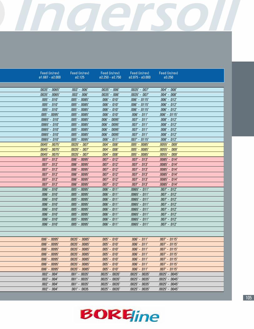
105
Feed (in/rev) Feed (in/rev) Feed (in/rev) Feed (in/rev) Feed (in/rev)ø1.687 - ø2.000 ø2.125 ø2.250 - ø2.750 ø2.875 - ø3.000 ø3.250
.0035" - .0065" .003" - .006" .0035" - .006" .0035" - .007" .004" - .008"
.0035" - .0065" .003" - .006" .0035" - .006" .0035" - .007" .004" - .008".005" - .010" .005" - .0085" .006" - .010" .006" - .0115" .006" - .012".005" - .010" .005" - .0085" .006" - .010" .006" - .0115" .006" - .012".005" - .010" .005" - .0085" .006" - .010" .006" - .0115" .006" - .012".005" - .0095" .005" - .0085" .006" - .010" .006" - .011" .006" - .0115".0065" - .010" .005" - .0085" .006" - .0095" .007" - .011" .008" - .012".0065" - .010" .005" - .0085" .006" - .0095" .007" - .011" .008" - .012".0065" - .010" .005" - .0085" .006" - .0095" .007" - .011" .008" - .012".0065" - .010" .005" - .0085" .006" - .0095" .007" - .011" .008" - .012".0065" - .010" .005" - .0095" .006" - .011" .007" - .0115" .008" - .012".0045" - .0075" .0035" - .007" .004" - .008" .005" - .0085" .0055" - .009".0045" - .0075" .0035" - .007" .004" - .008" .005" - .0085" .0055" - .009".0045" - .0075" .0035" - .007" .004" - .008" .005" - .0085" .0055" - .009".007" - .012" .006" - .0095" .007" - .012" .007" - .013" .0085" - .014".007" - .012" .006" - .0095" .007" - .012" .007" - .013" .0085" - .014".007" - .012" .006" - .0095" .007" - .012" .007" - .013" .0085" - .014".007" - .012" .006" - .0095" .007" - .012" .007" - .013" .0085" - .014".007" - .012" .006" - .0095" .007" - .012" .007" - .013" .0085" - .014".007" - .012" .006" - .0095" .007" - .012" .007" - .013" .0085" - .014".006" - .010" .005" - .0095" .006" - .011" .0065" - .011" .007" - .012".006" - .010" .005" - .0095" .006" - .011" .0065" - .011" .007" - .012".006" - .010" .005" - .0095" .006" - .011" .0065" - .011" .007" - .012".006" - .010" .005" - .0095" .006" - .011" .0065" - .011" .007" - .012".006" - .010" .005" - .0095" .006" - .011" .0065" - .011" .007" - .012".006" - .010" .005" - .0095" .006" - .011" .0065" - .011" .007" - .012".006" - .010" .005" - .0095" .006" - .011" .0065" - .011" .007" - .012".006" - .010" .005" - .0095" .006" - .011" .0065" - .011" .007" - .012"
.006" - .0095" .0035" - .0085" .005" - .010" .006" - .011" .007" - .0115"
.006" - .0095" .0035" - .0085" .005" - .010" .006" - .011" .007" - .0115"
.006" - .0095" .0035" - .0085" .005" - .010" .006" - .011" .007" - .0115"
.006" - .0095" .0035" - .0085" .005" - .010" .006" - .011" .007" - .0115"
.006" - .0095" .0035" - .0085" .005" - .010" .006" - .011" .007" - .0115"
.006" - .0095" .0035" - .0085" .005" - .010" .006" - .011" .007" - .0115"
.006" - .0095" .0035" - .0085" .005" - .010" .006" - .011" .007" - .0115".002" - .004" .001" - .0035" .0025" - .0035" .0025" - .0035" .0025" - .0045".002" - .004" .001" - .0035" .0025" - .0035" .0025" - .0035" .0025" - .0045".002" - .004" .001" - .0035" .0025" - .0035" .0025" - .0035" .0025" - .0045" .002" - .004" .001" - .0035 .0025" - .0035" .0025" - .0035" .0025" - .0045"
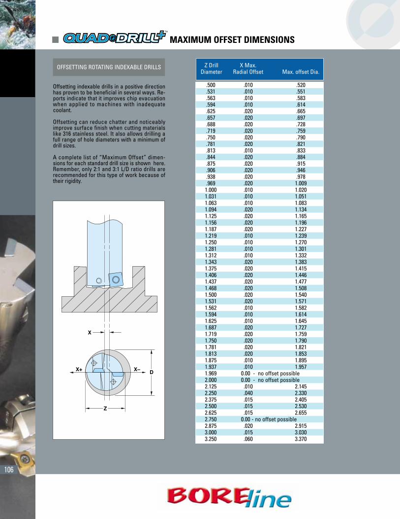
106
OFFSETTING ROTATING INDEXABLE DRILLS
Offsetting indexable drills in a positive directionhas proven to be beneficial in several ways. Re-ports indicate that it improves chip evacuationwhen applied to machines with inadequatecoolant.
Offsetting can reduce chatter and noticeablyimprove surface finish when cutting materialslike 316 stainless steel. It also allows drilling afull range of hole diameters with a minimum ofdrill sizes.
A complete list of “Maximum Offset” dimen-sions for each standard drill size is shown here.Remember, only 2:1 and 3:1 L/D ratio drills arerecommended for this type of work because oftheir rigidity.
Z Drill X Max. Diameter Radial Offset Max. offset Dia.
.500 .010 .520
.531 .010 .551
.563 .010 .583
.594 .010 .614
.625 .020 .665
.657 .020 .697
.688 .020 .728
.719 .020 .759
.750 .020 .790
.781 .020 .821
.813 .010 .833
.844 .020 .884
.875 .020 .915
.906 .020 .946
.938 .020 .978
.969 .020 1.0091.000 .010 1.0201.031 .010 1.0511.063 .010 1.0831.094 .020 1.1341.125 .020 1.1651.156 .020 1.1961.187 .020 1.2271.219 .010 1.2391.250 .010 1.2701.281 .010 1.3011.312 .010 1.3321.343 .020 1.3831.375 .020 1.4151.406 .020 1.4461.437 .020 1.4771.468 .020 1.5081.500 .020 1.5401.531 .020 1.5711.562 .010 1.5821.594 .010 1.6141.625 .010 1.6451.687 .020 1.7271.719 .020 1.7591.750 .020 1.7901.781 .020 1.8211.813 .020 1.8531.875 .010 1.8951.937 .010 1.9571.969 0.00 - no offset possible2.000 0.00 - no offset possible2.125 .010 2.1452.250 .040 2.3302.375 .015 2.4052.500 .015 2.5302.625 .015 2.6552.750 0.00 - no offset possible2.875 .020 2.9153.000 .015 3.0303.250 .060 3.370
� MAXIMUM OFFSET DIMENSIONS
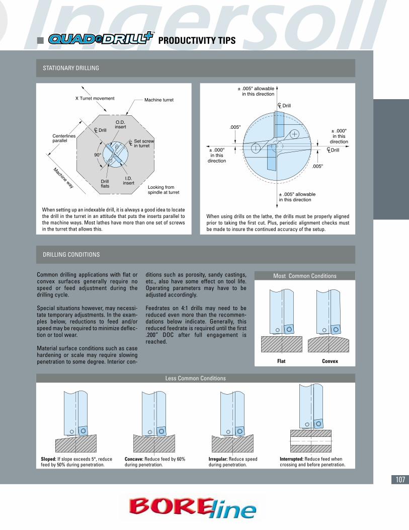
107
� PRODUCTIVITY TIPS
STATIONARY DRILLING
DRILLING CONDITIONS
When setting up an indexable drill, it is always a good idea to locatethe drill in the turret in an attitude that puts the inserts parallel tothe machine ways. Most lathes have more than one set of screwsin the turret that allows this.
When using drills on the lathe, the drills must be properly alignedprior to taking the first cut. Plus, periodic alignment checks mustbe made to insure the continued accuracy of the setup.
Less Common Conditions
Common drilling applications with flat orconvex surfaces generally require nospeed or feed adjustment during thedrilling cycle.
Special situations however, may necessi-tate temporary adjustments. In the exam-ples below, reductions to feed and/orspeed may be required to minimize deflec-tion or tool wear.
Material surface conditions such as casehardening or scale may require slowingpenetration to some degree. Interior con-
ditions such as porosity, sandy castings,etc., also have some effect on tool life.Operating parameters may have to beadjusted accordingly.
Feedrates on 4:1 drills may need to bereduced even more than the recommen-dations below indicate. Generally, thisreduced feedrate is required until the first.200” DOC after full engagement isreached.
Most Common Conditions
Flat Convex
Sloped: If slope exceeds 5°, reducefeed by 50% during penetration.
Interrupted: Reduce feed whencrossing and before penetration.
Concave: Reduce feed by 60%during penetration.
Irregular: Reduce speedduring penetration.
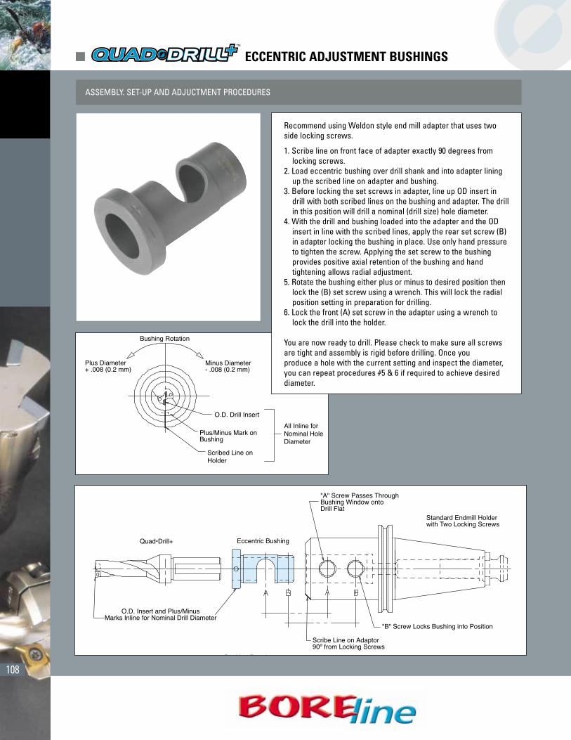
108
� ECCENTRIC ADJUSTMENT BUSHINGS
ASSEMBLY. SET-UP AND ADJUCTMENT PROCEDURES
Recommend using Weldon style end mill adapter that uses twoside locking screws.
1. Scribe line on front face of adapter exactly 90 degrees fromlocking screws.
2. Load eccentric bushing over drill shank and into adapter liningup the scribed line on adapter and bushing.
3. Before locking the set screws in adapter, line up OD insert indrill with both scribed lines on the bushing and adapter. The drillin this position will drill a nominal (drill size) hole diameter.
4. With the drill and bushing loaded into the adapter and the ODinsert in line with the scribed lines, apply the rear set screw (B)in adapter locking the bushing in place. Use only hand pressureto tighten the screw. Applying the set screw to the bushingprovides positive axial retention of the bushing and handtightening allows radial adjustment.
5. Rotate the bushing either plus or minus to desired position thenlock the (B) set screw using a wrench. This will lock the radialposition setting in preparation for drilling.
6. Lock the front (A) set screw in the adapter using a wrench tolock the drill into the holder.
You are now ready to drill. Please check to make sure all screwsare tight and assembly is rigid before drilling. Once youproduce a hole with the current setting and inspect the diameter,you can repeat procedures #5 & 6 if required to achieve desireddiameter.
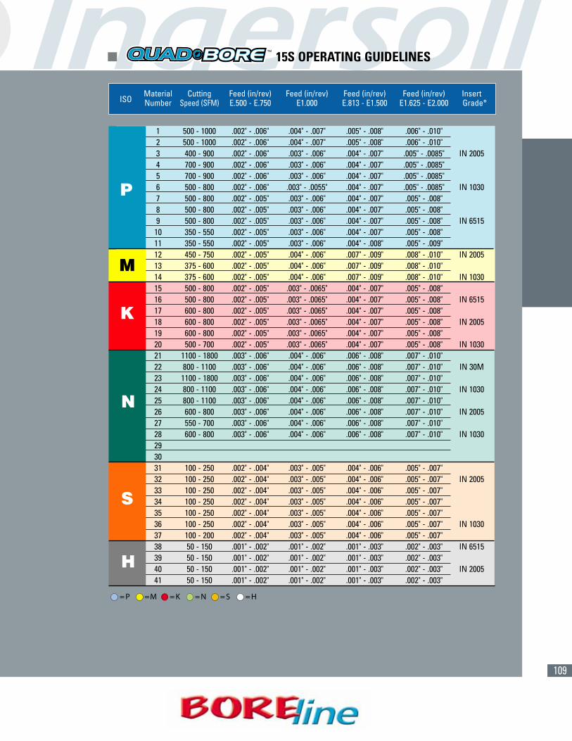
109
(CONT.)Material Cutting Feed (in/rev) Feed (in/rev) Feed (in/rev) Feed (in/rev) Insert
ISO Number Speed (SFM) E.500 - E.750 E1.000 E.813 - E1.500 E1.625 - E2.000 Grade*
1 500 - 1000 .002" - .006" .004" - .007" .005" - .008" .006" - .010"2 500 - 1000 .002" - .006" .004" - .007" .005" - .008" .006" - .010"3 400 - 900 .002" - .006" .003" - .006" .004" - .007" .005" - .0085" IN 20054 700 - 900 .002" - .006" .003" - .006" .004" - .007" .005" - .0085"5 700 - 900 .002" - .006" .003" - .006" .004" - .007" .005" - .0085"6 500 - 800 .002" - .006" .003" - .0055" .004" - .007" .005" - .0085" IN 10307 500 - 800 .002" - .005" .003" - .006" .004" - .007" .005" - .008"8 500 - 800 .002" - .005" .003" - .006" .004" - .007" .005" - .008"9 500 - 800 .002" - .005" .003" - .006" .004" - .007" .005" - .008" IN 651510 350 - 550 .002" - .005" .003" - .006" .004" - .007" .005" - .008"11 350 - 550 .002" - .005" .003" - .006" .004" - .008" .005" - .009"12 450 - 750 .002" - .005" .004" - .006" .007" - .009" .008" - .010" IN 200513 375 - 600 .002" - .005" .004" - .006" .007" - .009" .008" - .010"14 375 - 600 .002" - .005" .004" - .006" .007" - .009" .008" - .010" IN 103015 500 - 800 .002" - .005" .003" - .0065" .004" - .007" .005" - .008"16 500 - 800 .002" - .005" .003" - .0065" .004" - .007" .005" - .008" IN 651517 600 - 800 .002" - .005" .003" - .0065" .004" - .007" .005" - .008"18 600 - 800 .002" - .005" .003" - .0065" .004" - .007" .005" - .008" IN 200519 600 - 800 .002" - .005" .003" - .0065" .004" - .007" .005" - .008"20 500 - 700 .002" - .005" .003" - .0065" .004" - .007" .005" - .008" IN 103021 1100 - 1800 .003" - .006" .004" - .006" .006" - .008" .007" - .010"22 800 - 1100 .003" - .006" .004" - .006" .006" - .008" .007" - .010" IN 30M23 1100 - 1800 .003" - .006" .004" - .006" .006" - .008" .007" - .010"24 800 - 1100 .003" - .006" .004" - .006" .006" - .008" .007" - .010" IN 103025 800 - 1100 .003" - .006" .004" - .006" .006" - .008" .007" - .010"26 600 - 800 .003" - .006" .004" - .006" .006" - .008" .007" - .010" IN 200527 550 - 700 .003" - .006" .004" - .006" .006" - .008" .007" - .010"28 600 - 800 .003" - .006" .004" - .006" .006" - .008" .007" - .010" IN 1030293031 100 - 250 .002" - .004" .003" - .005" .004" - .006" .005" - .007"32 100 - 250 .002" - .004" .003" - .005" .004" - .006" .005" - .007" IN 200533 100 - 250 .002" - .004" .003" - .005" .004" - .006" .005" - .007"34 100 - 250 .002" - .004" .003" - .005" .004" - .006" .005" - .007"35 100 - 250 .002" - .004" .003" - .005" .004" - .006" .005" - .007"36 100 - 250 .002" - .004" .003" - .005" .004" - .006" .005" - .007" IN 103037 100 - 200 .002" - .004" .003" - .005" .004" - .006" .005" - .007"38 50 - 150 .001" - .002" .001" - .002" .001" - .003" .002" - .003" IN 651539 50 - 150 .001" - .002" .001" - .002" .001" - .003" .002" - .003"40 50 - 150 .001" - .002" .001" - .002" .001" - .003" .002" - .003" IN 200541 50 - 150 .001" - .002" .001" - .002" .001" - .003" .002" - .003"
� 15S OPERATING GUIDELINES
P
M
K
N
S
H
= P =M = K = N = S = H

110
(CONT.)Material Cutting Feed (in/rev) Feed (in/rev) Feed (in/rev) Feed (in/rev) InsertISO Number Speed (SFM) E.438 - ø.719 E.812 E1.000 - ø1.500 E1.750 - ø2.000 Grade*
1 500 - 1000 .004" - .010" .006" - .011" .008" - .014" .010" - .016"2 500 - 1000 .004" - .010" .006" - .011" .008" - .014" .010" - .016"3 400 - 900 .004" - .010" .004" - .011" .007" - .012" .010" - .017" IN 20054 700 - 900 .004" - .010" .004" - .011" .007" - .012" .010" - .017"5 700 - 900 .004" - .010" .004" - .011" .007" - .012" .010" - .017"6 500 - 800 .004" - .010" .004" - .011" .007" - .012" .010" - .017" IN 10307 500 - 800 .004" - .009" .004" - .011" .007" - .012" .009" - .015"8 500 - 800 .004" - .009" .004" - .011" .007" - .012" .009" - .015"9 500 - 800 .004" - .009" .004" - .011" .007" - .012" .009" - .015" IN 651510 350 - 550 .004" - .009" .004" - .011" .007" - .012" .009" - .015"11 350 - 550 .004" - .009" .004" - .011" .008" - .014" .010" - .016"12 450 - 750 .004" - .009" .006" - .010" .012" - .016" .014" - .018" IN 200513 375 - 600 .004" - .009" .006" - .010" .012" - .016" .014" - .018"14 375 - 600 .004" - .009" .006" - .010" .012" - .016" .014" - .018" IN 103015 500 - 800 .004" - .009" .004" - .010" .007" - .013" .010" - .015"16 500 - 800 .004" - .009" .004" - .010" .007" - .013" .010" - .015" IN 651517 600 - 800 .004" - .009" .004" - .010" .007" - .013" .010" - .015"18 600 - 800 .004" - .009" .004" - .010" .007" - .013" .010" - .015" IN 200519 600 - 800 .004" - .009" .004" - .010" .007" - .013" .010" - .015"20 500 - 700 .004" - .009" .004" - .010" .007" - .013" .010" - .015" IN 103021 1100 - 1800 .006" - .011" .006" - .010" .012" - .015" .013" - .018"22 800 - 1100 .006" - .011" .006" - .010" .012" - .015" .013" - .018" IN 30M23 1100 - 1800 .006" - .011" .006" - .010" .012" - .015" .013" - .018"24 800 - 1100 .006" - .011" .006" - .010" .012" - .015" .013" - .018"25 800 - 1100 .006" - .011" .006" - .010" .012" - .015" .013" - .018" IN 103026 600 - 800 .006" - .011" .006" - .010" .012" - .015" .013" - .018"27 550 - 700 .006" - .011" .006" - .010" .012" - .015" .013" - .018"28 600 - 800 .006" - .011" .006" - .010" .012" - .015" .013" - .018" IN 1030293031 100 - 250 .004" - .007" .004" - .008" .007" - .011" .009" - .013"32 100 - 250 .004" - .007" .004" - .008" .007" - .011" .009" - .013" IN 200533 100 - 250 .004" - .007" .004" - .008" .007" - .011" .009" - .013"34 100 - 250 .004" - .007" .004" - .008" .007" - .011" .009" - .013"35 100 - 250 .004" - .007" .004" - .008" .007" - .011" .009" - .013"36 100 - 250 .004" - .007" .004" - .008" .007" - .011" .009" - .013" IN 103037 100 - 200 .004" - .007" .004" - .008" .007" - .011" .009" - .013"38 50 - 150 .002" - .003" .002" - .003" .002" - .005" .004" - .006" IN 651539 50 - 150 .002" - .003" .002" - .003" .002" - .005" .004" - .006"40 50 - 150 .002" - .003" .002" - .003" .002" - .005" .004" - .006" IN 200541 50 - 150 .002" - .003" .002" - .003" .002" - .005" .004" - .006"
� 15C OPERATING GUIDELINES
P
M
K
N
S
H
= P =M = K = N = S = H

111
(CONT.)
P
M
K
N
S
H
Material Cutting Speed Cutting Speed Cutting SpeedISO Number (SFM) (SFM) (SFM)
ø.078 - ø.197 ø.198 - ø.512 ø.513 - ø1.575
1 230 - 300 260 - 360 230 - 3302 230 - 300 260 - 360 230 - 3303 165 - 230 200 - 260 165 - 2304 230 - 300 260 - 360 230 - 3305 165 - 230 200 - 260 165 - 2306 200 - 260 230 - 300 200 - 2607 165 - 230 200 - 260 165 - 2308 165 - 230 200 - 260 165 - 2309 165 - 230 200 - 260 165 - 23010 165 - 230 200 - 260 165 - 23011 165 - 230 200 - 260 165 - 23012 165 - 230 165 - 230 165 - 23013 165 - 230 165 - 230 165 - 23014 165 - 230 165 - 230 165 - 23015 200 - 260 230 - 300 230 - 30016 200 - 260 230 - 300 230 - 30017 200 - 260 230 - 300 230 - 30018 200 - 260 230 - 300 230 - 30019 200 - 260 230 - 300 230 - 30020 200 - 260 230 - 300 230 - 30021 230 - 590 330 - 1000 330 - 100022 230 - 590 330 - 1000 330 - 100023 230 - 590 330 - 1000 330 - 100024 230 - 590 330 - 1000 330 - 100025 230 - 590 330 - 1000 330 - 100026 230 - 390 330 - 520 260 - 53027 230 - 390 330 - 520 260 - 53028 230 - 390 330 - 520 260 - 53029303132333435363738394041
� GUN DRILL OPERATING GUIDELINES

112
� GUN DRILL COOLANT AND OPERATING GUIDELINES
THE RIGHT COOLANT
CUTTING CONDITIONS
Neat Oil• Oil is preferred over water soluable coolant• Most conventional gundrilling machines use oil• Provides superior lubricity, better tool life and surface finish• No worry about concentration levels• Does not evaporate
Water Soluable• Used on most CNC machines
<8% = unacceptable10-12% = acceptable12-15% = preferred
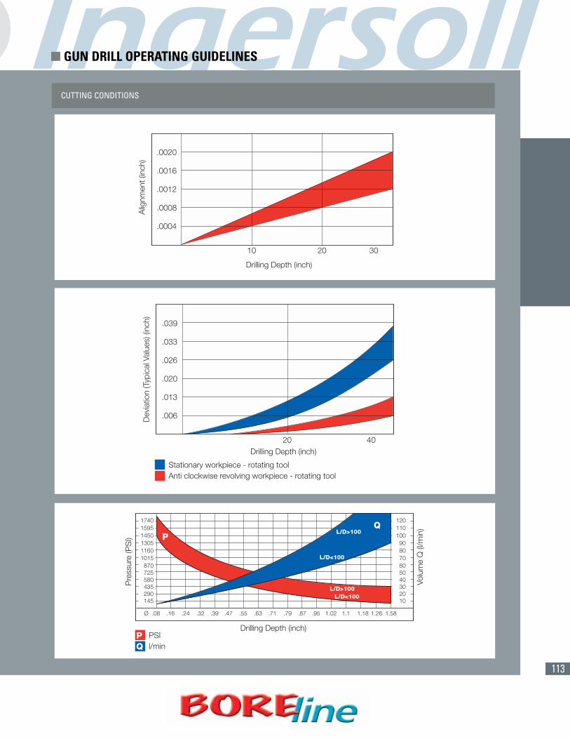
113
CUTTING CONDITIONS
� GUN DRILL OPERATING GUIDELINES
114
Part Number Page Part Number Page
� INDEX - DRILLS / INSERTS / HARDWARE
15C1D-0400884R01 3715C1D-0500884R01 3715C1D-0601084R01 3715C1D-0701084R01 3715C1E-0801284R01 3715C1G-1001580R01 3715C1G-1102080R01 3715C1G-1202080R01 3715C1G-1302281R01 3715C1G-1502281R01 3715C1G-1503781R01 3715C1J-1702681R01 3715C1J-2003081R01 3715S1D-0500884R01 3615S1D-0601084R01 3615S1D-0701084R01 3615S1D-0701284R01 3615S1F-1001580R01 3615S1G-0801284R01 3615S1G-0801284R02 3615S1G-1102080R01 3615S1G-1202080R01 3615S1G-1302281R01 3615S1G-1502281R01 3615S1J-1602381R01 3615S1J-1702681R01 3615S1J-2003081R01 36BU16-16 35BU24-44 35BU32-02 35CB100-01 24CB105-01 24CB110-01 24CB115-01 24CB120-01 24CB125-02 24CB130-01 24CB135-01 24CB140-01 24CB145-01 24CB150-01 24CB160-01 24CB170-02 24CB180-01 24CB190-01 24CB200-01 24DR0300024T7R01 14
DR0310023T7R01 14DR0320023T7R01 14DR0320023T7R01 14DR0330023T7R01 14DR0340023T7R01 14DR0350023T7R01 14DR0360023T7R01 14DR0370022T7R01 14DR0380030T7R01 14DR0390030T7R01 14DR0400030T7R01 14DR0410030T7R01 14DR0420030T7R01 14DR0430030T7R01 14DR0440029T7R01 14DR0450029T7R01 14DR0460029T7R01 14DR0470029T7R01 14DR0480037T7R01 14DR0480037T7R01 14DR0490037T7R01 14DR0500037T7R01 14DR0510036T7R01 14DR0520036T7R01 14DR0530036T7R01 14DR0540036T7R01 14DR0550036T7R01 14DR0560036T7R01 14DR0570035T7R01 14DR0580035T7R01 14DR0590035T7R01 14DR0600035T7R01 14DR0610044T0R01 14DR0620044T0R01 14DR0630044T0R01 14DR0635043R6R01 14DR0640043T0R01 14DR0650043T0R01 15DR0660043T0R01 15DR0670043T0R01 15DR0680043T0R01 15DR0690043T0R01 15DR0700043T0R01 15DR0710042T0R01 15DR0720042T0R01 15DR0730042T0R01 15DR0740042T0R01 15

115
Part Number Page Part Number Page
DR0650043T0R01 15DR0660043T0R01 15DR0670043T0R01 15DR0675043R7R01 15DR0680043T0R01 15DR0690043T0R01 15DR0700043T0R01 15DR0710042T0R01 15DR0714042R7R01 15DR0720042T0R01 15DR0730042T0R01 15DR0740042T0R01 15DR0750042T0R01 15DR0760042T0R01 15DR0770041T0R01 15DR0780041T0R01 15DR0790041T0R01 15DR0800041T0R01 15DR0810049T1R01 15DR0820049T1R01 15DR0830049T1R01 15DR0840048T1R01 15DR0850048T1R01 15DR0860048T1R01 15DR0870048T1R01 15DR0880048T1R01 15DR0890048T1R01 15DR0900048T1R01 15DR0910047T1R01 15DR0920047T1R01 15DR0930047T1R01 15DR0940047T1R01 15DR0950047T1R01 15DR0960047T1R01 15DR0970046T1R01 15DR0980046T1R01 15DR0990046T1R01 15DR1000046T1R01 15DR1010056T2R01 15DR1020056T2R01 15DR1030056T2R01 15DR1040055T2R01 15DR1050055T2R01 15DR1060055T2R01 15DR1070055T2R01 15DR1080055T2R01 15DR1090055T2R01 15
DR1100055T2R01 15DR1110054R9R01 16DR1120054T2R01 15DR1130054T2R01 15DR1140054T2R01 15DR1160054T2R01 15DR1170054T2R01 15DR1150054T2R01 15DR1180053T2R01 15DR1191053S4R01 15DR1200053T2R01 15DR1210059T8R01 16DR1220059T8R01 16DR1230053S4R01 16DR1240058T8R01 16DR1250058T8R01 16DR1270058S4R01 16DS-H05HB 21, 24DS-HH06T 21, 24DS-T07F 22, 34, 36DS-T08W 21, 34DS-T09W 11DS-T10T 34DS-T15T 34, 36DS-T15HB 21, 24DS-T20T 34, 36DS-T25HB 24DS-TP06S 34FAK-0611884K01 10FAK-0611884R01 10FAK-0708284K01 10FAK-0708284R01 10FAK-0713584K01 10FAK-0713584R01 10FAK-0714484K01 10FAK-0714484R01 10FAK-0809084K01 10FAK-0809084R01 10GOMT060230R 23GOMT060245R 23GOMT060260R 23GOMT080330R 23GOMT080345R 23GOMT080360R 23KOMT050104R 23MHK018047DBR01 22MHK019047DBR01 22
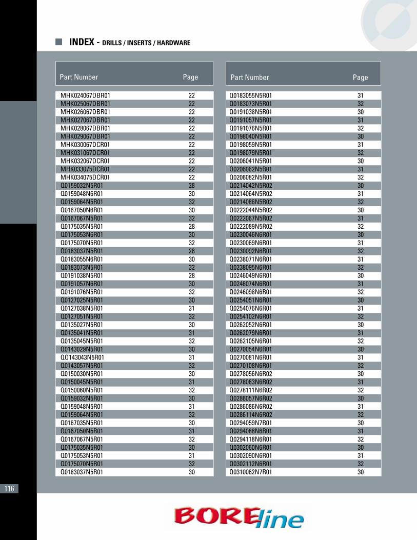
116
Part Number Page Part Number Page
� INDEX - DRILLS / INSERTS / HARDWARE
MHK024067DBR01 22MHK025067DBR01 22MHK026067DBR01 22MHK027067DBR01 22MHK028067DBR01 22MHK029067DBR01 22MHK030067DCR01 22MHK031067DCR01 22MHK032067DCR01 22MHK033075DCR01 22MHK034075DCR01 22Q0159032N5R01 28Q0159048N6R01 30Q0159064N5R01 32Q0167050N6R01 30Q0167067N5R01 32Q0175035N5R01 28Q0175053N6R01 30Q0175070N5R01 32Q0183037N5R01 28Q0183055N6R01 30Q0183073N5R01 32Q0191038N5R01 28Q0191057N6R01 30Q0191076N5R01 32Q0127025N5R01 30Q0127038N5R01 31Q0127051N5R01 32Q0135027N5R01 30Q0135041N5R01 31Q0135045N5R01 32Q0143029N5R01 30QO143043N5R01 31Q0143057N5R01 32Q0150030N5R01 30Q0150045N5R01 31Q0150060N5R01 32Q0159032N5R01 30Q0159048N5R01 31Q0159064N5R01 32Q0167035N5R01 30Q0167050N5R01 31Q0167067N5R01 32Q0175035N5R01 30Q0175053N5R01 31Q0175070N5R01 32Q0183037N5R01 30
Q0183055N5R01 31Q0183073N5R01 32Q0191038N5R01 30Q0191057N5R01 31Q0191076N5R01 32Q0198040N5R01 30Q0198059N5R01 31Q0198079N5R01 32Q0206041N5R01 30Q0206062N5R01 31Q0206082N5R01 32Q0214042N5R02 30Q0214064N5R02 31Q0214086N5R02 32Q0222044N5R02 30Q0222067N5R02 31Q0222089N5R02 32Q0230046N6R01 30Q0230069N6R01 31Q0230092N6R01 32Q0238071N6R01 31Q0238095N6R01 32Q0246049N6R01 30Q0246074N6R01 31Q0246098N6R01 32Q0254051N6R01 30Q0254076N6R01 31Q0254102N6R01 32Q0262052N6R01 30Q0262079N6R01 31Q0262105N6R01 32Q0270054N6R01 30Q0270081N6R01 31Q0270108N6R01 32Q0278056N6R02 30Q0278083N6R02 31Q0278111N6R02 32Q0286057N6R02 30Q0286086N6R02 31Q0286114N6R02 32Q0294059N7R01 30Q0294088N6R01 31Q0294118N6R01 32Q0302060N6R01 30Q0302090N6R01 31Q0302112N6R01 32Q0310062N7R01 30

117
Part Number Page Part Number Page
Q0437175N6R01 32Q0445089N6R01 30Q0445134N6R01 31Q0445178N6R01 32Q0452090N7R01 30Q0452136N7R01 31Q0452181N7R01 32Q0460092N7R01 30Q0460138N7R01 31Q0460184N7R01 32Q0460095N7R01 30Q0476143N7R01 31Q0476190N7R01 32Q0492098N7R01 30Q0492148N7R01 31Q0492197N7R01 32Q0500100N7R01 30Q0500150N7R01 31Q0500200N7R01 32Q0508102N7R01 30Q0508152N7R01 31Q0508203N7R01 32Q0539108N8R01 33Q0539162N8R01 33Q0571111N8R01 33Q0571172N8R01 33Q0603121N8R01 33Q0603181N8R01 33Q0635127N8R01 33Q0635191N8R01 33Q0666133N8R01 33Q0666200N8R01 33Q0698140N8R01 33Q0698210N8R01 33Q0730146N8R01 33Q0730219N8R01 33Q0762152N8R01 33Q0762229N8R01 33Q0825165N8R01 33Q0825248N8R01 33SA060-02 21SA100-02 21SC060-02 21SC100-02 21SD050-A5 24SD060-20 24SCLT050204N-PH 34
Q0310093N6R01 31Q0310124N7R01 32Q0310662N6R01 30Q0318063N6R01 30Q0318095N6R01 31Q0318127N6R01 32Q0325065N6R01 30Q0325098N6R01 31Q0325130N6R01 32Q0333067N6R01 30Q0333100N6R01 31Q0333133N6R01 32Q0341068N6R02 30Q0341102N6R02 31Q0341136N6R02 32Q0349070N6R02 30Q0349105N6R02 31Q0349140N6R02 32Q0357071N6R02 30Q0357107N6R02 31Q0357143N6R02 32Q0365073N6R01 30Q0365110N6R01 31Q0365146N6R01 32Q0373075N6R01 30Q0373112N6R01 31Q0373149N6R01 32Q0381076N6R01 30Q0381114N6R01 31Q0381152N6R01 32Q0389078N6R01 30Q0389117N6R01 31Q0389156N6R01 32Q0397079N6R01 30Q0397119N6R01 31Q0397159N6R01 32Q0405081N6R01 30Q0405122N6R01 31Q0405162N6R01 32Q0413083N6R01 30Q0413124N6R01 31Q0413165N6R01 32Q0428086N6R02 30Q0428128N6R02 31Q0428171N6R01 32Q0437087N6R01 30Q0437131N6R01 31
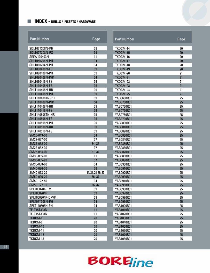
118
Part Number Page Part Number Page
� INDEX - DRILLS / INSERTS / HARDWARE
SDLT07T308N-PH 39SDLT07T308N-PS 39SELW100403N 11SHLT050204N-PH 34SHLT060204N-PH 34SHLT090408N-FS 39SHLT090408N-PH 39SHLT090408N-PH1 34 SHLT090416N-FS 39SHLT110408N-FS 39SHLT110408N-HR 39SHLT110408N-PH 39SHLT110408TN-PH 39SHLT110408N-PH1 34SHLT110408N-HR 39SHLT110416N-FS 39SHLT140508TN-HR 39SHLT140508N-FS 39SHLT140508N-PH 39SHLT140508N-HR 39SHLT140516N-FS 39SM20-043-00 34SM22-037-00 37SM22-052-00 34, 36SM22-052-30 37SM25-064-00 21, 34SM30-065-00 11SM30-065-20 37SM35-088-60 34SM40-080-30 36SM40-093-20 11, 21, 24, 36, 37SM50-096-20 36, 37SM50-122-50 34SM50-127-10 36, 37SPLT060204-DM 39SPLT060204R 39SPLT060204R-DM04 39SPLT07T308N-PH 34SPLT140508N-PH 34TFLT15T303N 11TFLT15T308N 11TKDCM-8 20TKDCM-9 20TKDCM-10 20TKDCM-11 20TKDCM-12 20TKDCM-13 20
TKDCM-14 20TKDCM-15 20TKDCM-16 20TKDCM-17 20TKDCM-18 20TKDCM-19 20TKDCM-20 21TKDCM-21 21TKDCM-22 21TKDCM-23 21TKDCM-24 21TKDCM-25 21YAB0680R01 25YAB0750R01 25YAB0760R01 25YAB0770R01 25YAB0780R01 25YAB0790R01 25YAB0800R01 25YAB0810R01 25YAB0820R01 25YAB0830R01 25YAB0840R01 25YAB0850R01 25YAB0860R01 25YAB0870R01 25YAB0880R01 25YAB0890R01 25YAB0900R01 25YAB0910R01 25YAB0920R01 25YAB0930R01 25YAB0940R01 25YAB0950R01 25YAB0960R01 25YAB0970R01 25YAB0980R01 25YAB0990R01 25YAB1000R01 25YAB1010R01 25YAB1020R01 25YAB1030R01 25YAB1040R01 25YAB1050R01 25YAB1060R01 25YAB1070R01 25YAB1080R01 25
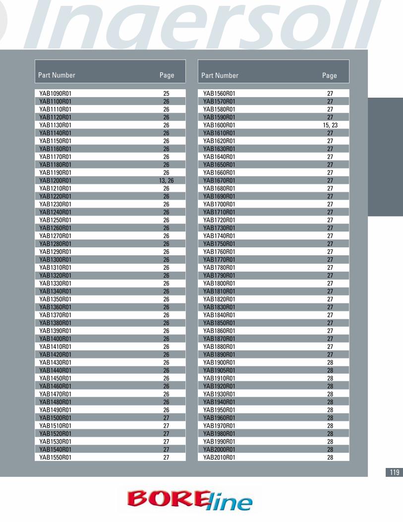
119
Part Number Page Part Number Page
YAB1090R01 25YAB1100R01 26YAB1110R01 26YAB1120R01 26YAB1130R01 26YAB1140R01 26YAB1150R01 26YAB1160R01 26YAB1170R01 26YAB1180R01 26YAB1190R01 26YAB1200R01 13, 26YAB1210R01 26YAB1220R01 26YAB1230R01 26YAB1240R01 26YAB1250R01 26YAB1260R01 26YAB1270R01 26YAB1280R01 26YAB1290R01 26YAB1300R01 26YAB1310R01 26YAB1320R01 26YAB1330R01 26YAB1340R01 26YAB1350R01 26YAB1360R01 26YAB1370R01 26YAB1380R01 26YAB1390R01 26YAB1400R01 26YAB1410R01 26YAB1420R01 26YAB1430R01 26YAB1440R01 26YAB1450R01 26YAB1460R01 26YAB1470R01 26YAB1480R01 26YAB1490R01 26YAB1500R01 27YAB1510R01 27YAB1520R01 27YAB1530R01 27YAB1540R01 27YAB1550R01 27
YAB1560R01 27YAB1570R01 27YAB1580R01 27YAB1590R01 27YAB1600R01 15, 23YAB1610R01 27YAB1620R01 27YAB1630R01 27YAB1640R01 27YAB1650R01 27YAB1660R01 27YAB1670R01 27YAB1680R01 27YAB1690R01 27YAB1700R01 27YAB1710R01 27YAB1720R01 27YAB1730R01 27YAB1740R01 27YAB1750R01 27YAB1760R01 27YAB1770R01 27YAB1780R01 27YAB1790R01 27YAB1800R01 27YAB1810R01 27YAB1820R01 27YAB1830R01 27YAB1840R01 27YAB1850R01 27YAB1860R01 27YAB1870R01 27YAB1880R01 27YAB1890R01 27YAB1900R01 28YAB1905R01 28YAB1910R01 28YAB1920R01 28YAB1930R01 28YAB1940R01 28YAB1950R01 28YAB1960R01 28YAB1970R01 28YAB1980R01 28YAB1990R01 28YAB2000R01 28YAB2010R01 28

120
YAB2490R01 29YAB2500R01 29YAB2510R01 29YAB2520R01 29YAB2530R01 29YAB2540R01 29YAB2550R01 29YAB2560R01 29YAB2570R01 29YAB2580R01 29YAB2590R01 29YB1200006S5R01 12YB1600008S7R01 12YBB0680R01 25YBB0750R01 25YBB0760R01 25YBB0770R01 25YBB0780R01 25YBB0790R01 25YBB0800R01 25YBB0810R01 25YBB0820R01 25YBB0830R01 25YBB0840R01 25YBB0850R01 25YBB0860R01 25YBB0870R01 25YBB0880R01 25YBB0890R01 25YBB0900R01 25YBB0910R01 25YBB0920R01 25YBB0930R01 25YBB0940R01 25YBB0950R01 25YBB0960R01 25YBB0970R01 25YBB0980R01 25YBB0990R01 25YBB1000R01 25YBB1010R01 25YBB1020R01 25YBB1030R01 25YBB1040R01 25YBB1050R01 25YBB1060R01 25YBB1070R01 25
YAB2020R01 28YAB2030R01 28YAB2040R01 28YAB2050R01 28YAB2060R01 28YAB2070R01 28YAB2080R01 28YAB2090R01 28YAB2100R01 28YAB2110R01 28YAB2120R01 28YAB2130R01 28YAB2140R01 28YAB2150R01 28YAB2160R01 28YAB2170R01 28YAB2180R01 28YAB2190R01 28YAB2200R01 28YAB2210R01 28YAB2220R01 28YAB2230R01 28YAB2240R01 28YAB2250R01 28YAB2260R01 28YAB2270R01 28YAB2280R01 28YAB2290R01 28YAB2300R01 29YAB2310R01 29YAB2320R01 29YAB2330R01 29YAB2340R01 29YAB2350R01 29YAB2360R01 29YAB2370R01 29YAB2380R01 29YAB2390R01 29YAB2400R01 29YAB2410R01 29YAB2420R01 29YAB2430R01 29YAB2440R01 29YAB2450R01 29YAB2460R01 29YAB2470R01 29YAB2480R01 29
Part Number Page Part Number Page
� INDEX - DRILLS / INSERTS / HARDWARE

121
YBB1550R01 27YBB1560R01 27YBB1570R01 27YBB1580R01 27YBB1590R01 27YBB1600R01 27YBB1610R01 27YBB1620R01 27YBB1630R01 27YBB1640R01 27YBB1650R01 27YBB1660R01 27YBB1670R01 27YBB1680R01 27YBB1690R01 27YBB1700R01 27YBB1710R01 27YBB1720R01 27YBB1730R01 27YBB1740R01 27YBB1750R01 27YBB1760R01 27YBB1770R01 27YBB1780R01 27YBB1790R01 27YBB1800R01 27YBB1810R01 27YBB1820R01 27YBB1830R01 27YBB1840R01 27YBB1850R01 27YBB1860R01 27YBB1870R01 27YBB1880R01 27YBB1890R01 27YBB1900R01 28YBB1905R01 28YBB1910R01 28YBB1920R01 28YBB1930R01 28YBB1940R01 28YBB1950R01 28YBB1960R01 28YBB1970R01 28YBB1980R01 28YBB1990R01 28YBB2000R01 28
YBB1080R01 25YBB1090R01 25YBB1100R01 26YBB1110R01 26YBB1120R01 26YBB1130R01 26YBB1140R01 26YBB1150R01 26YBB1160R01 26YBB1170R01 26YBB1180R01 26YBB1190R01 26YBB1200R01 26YBB1210R01 26YBB1220R01 26YBB1230R01 26YBB1240R01 26YBB1250R01 26YBB1260R01 26YBB1270R01 26YBB1280R01 26YBB1290R01 26YBB1300R01 26YBB1310R01 26YBB1320R01 26YBB1330R01 26YBB1340R01 26YBB1350R01 26YBB1360R01 26YBB1370R01 26YBB1380R01 26YBB1390R01 26YBB1400R01 26YBB1410R01 26YBB1420R01 26YBB1430R01 26YBB1440R01 26YBB1450R01 26YBB1460R01 26YBB1470R01 26YBB1480R01 26YBB1490R01 26YBB1500R01 27YBB1510R01 27YBB1520R01 27YBB1530R01 27YBB1540R01 27
Part Number Page Part Number Page

122
YBB2480R01 29YBB2490R01 29YBB2500R01 29YBB2510R01 29YBB2520R01 29YBB2530R01 29YBB2540R01 29YBB2550R01 29YBB2560R01 29YBB2570R01 29YBB2580R01 29YBB2590R01 29YC0680021SKR00 22YC0830026SKR00 22YC1000030SKR00 22YC1200035SMR00 22YC1400039SPR00 22YC1730042SRR00 22YC2100048SSR00 22YC0770025RHR01 22YC0820025RHR01 22YC0910026RHR01 22YC1050026RHR01 22YC1130026RHR01 22YC1210026RHR01 22YC1300026RHR01 22YC1330030RJR01 22YC1450030RJR01 22YC1650035RJR01 22YC1730035RLR01 22YC1920041RLR01 22YC2040041RLR01 22YCB1200R01 13YCB1600R01 13YD0750022B9R01 16YD0750026SDR00 19YD0750037B9R01 17YD0800024B9R01 16YD0800028SDR00 16YD0800129SER00 19YD0800040B9R01 17YD0850025B9R01 16YD0850042B9R01 17YD0900027B9R01 16YD0900045B9R01 17YD0950028B9R01 16YD0950033SFR00 19
YBB2010R01 28YBB2020R01 28YBB2030R01 28YBB2040R01 28YBB2050R01 28YBB2060R01 28YBB2070R01 28YBB2080R01 28YBB2090R01 28YBB2100R01 28YBB2110R01 28YBB2120R01 28YBB2130R01 28YBB2140R01 28YBB2150R01 28YBB2160R01 28YBB2170R01 28YBB2180R01 28YBB2190R01 28YBB2200R01 28YBB2210R01 28YBB2220R01 28YBB2230R01 28YBB2240R01 28YBB2250R01 28YBB2260R01 28YBB2270R01 28YBB2280R01 28YBB2290R01 28YBB2300R01 29YBB2310R01 29YBB2320R01 29YBB2330R01 29YBB2340R01 29YBB2350R01 29YBB2360R01 29YBB2370R01 29YBB2380R01 29YBB2390R01 29YBB2400R01 29YBB2410R01 29YBB2420R01 29YBB2430R01 29YBB2440R01 29YBB2450R01 29YBB2460R01 29YBB2470R01 29
Part Number Page Part Number Page
� INDEX - DRILLS / INSERTS / HARDWARE

123
YD170013618R01 18YD1800054C8R01 16YD1800060SPR01 19YD1800090C8R01 17YD1800144C8R01 18YD1900057C8R01 16YD1900062SQR00 19YD1900095C8R01 17YD1900152C8R01 18YD2000060C8R01 16YD2000066SRR00 19YD2000100C8R01 17YD2000160C8R01 18YD2100063C8R01 16YD2100105C8R01 17YD2200066C8R01 16YD2200110C8R01 17YD2300069C8R01 16YD2300115C8R01 17YD2400072C8R01 16YD2400120C8R01 17YD2500075C8R01 16YD2500125C8R01 17ZOMW090700R 24
YD0950047B9R01 17YD1000030C0R01 16YD1000050C0R01 17YD1000050C0R01 19YD1000080C0R01 16YD1050031C0R01 18YD1050034SGR00 19YD1050052C0R01 17YD1100033C0R01 16YD1100036SGR00 19YD1100055C0R01 17YD1100088C0R01 18YD1150034C0R01 16YD1150038SHR00 19YD1150057C0R01 17YD1200036C0R01 16YD1200042SHR00 19YD1200060C0R01 17YD1200096C0R01 18YD1250037C0R01 16YD1250042SJR00 19YD1250062C0R01 17YD1300039C0R01 16YD1300042SJR00 19YD1300065C0R01 17YD1300104C0R01 18YD1350040C0R01 16YD1350044SKR00 19YD1350067C0R01 17YD1400042C0R01 16YD1400048SKR00 19YD1400070C0R01 17YD1400112C0R01 18YD1450043C0R01 16YD1450050SLR00 19YD1450072C0R01 17YD150004518R01 16YD1500052SLR00 19YD150007518R01 17YD150012018R01 18YD160004818R01 16YD1600052SMR00 19YD160008018R01 17YD160012818R01 18YD170005118R01 16YD1700055SNR00 19YD170008518R01 17
Part Number Page Part Number Page

Ingersoll Cutting Tools for the Americas
Marketing & Technology Center845 S. Lyford RoadRockford, IL 61108-2749 U.S.A.Tel: 815.387.6600Fax: 815.387.6968Email: [email protected]: www.ingersoll-imc.com
Ingersoll Cutting Tool Ltd.4510 Rhodes Drive, Unit #100Windsor, Ontario N8W 5K5, CanadaTel: 519.974.1019Fax: 519.974.2260
Ingersoll Cutting Tools de México S.A. de C.V.Carr. Saltillo Monterrey Km. 5.5, Local 2 y 3Saltillo, Coahuila C.P. 25200, MéxicoTel: (844) 432.2546, (844) 432.2547Fax: (844) 432.2544
Ingersoll Cutting Tools for Europe
Marketing & Technology CenterIngersoll Werkzeuge GmbHKalteiche-Ring 21-2535708 Haiger, GermanyTel: 02773.742 0Fax: 02773.742 812/814Email: [email protected]: www.ingersoll-imc.de
CAT-002-2 (2-06) Printed in Israel