instruction manual for 」で区切る。不要の場 … you for purchasing the hioki "3560 ac...
TRANSCRIPT

INSTRUCTION MANUALFor...は専用機種。複数の場合は「/」で区切る。不要の場合はとる。
形名を入力。 複数の場合は「/」で区切る。
3560品名を入力。
AC mΩ HiTESTER

Contents
Introduction i
Inspection i
Safety Notes ii
Notes on Use iv
Chapter Summary v
Chapter 1 Overview 1
1.1 Product Overview 1
1.2 Features 2
1.3 Identification of Controls and Indicators 3
1.3.1 Fluorescent Character Display Tube 3
1.3.2 Front Panel 4
1.3.3 Rear Panel / Side Panel 6
Chapter 2 Specifications 7
2.1 General Specifications 7
2.2 Measurement Range 9
2.3 External Dimensions 10
Chapter 3 Preparing for Measurement 11
3.1 Mounting the Interface 11
3.2 Connecting the Power Cord 12
3.3 Connecting the Measurement Leads 13
3.4 Powering On/Off 14
3.5 Setting the Power Supply Frequency 15
3.6 Instrument Handle 16
Chapter 4 Measurement Procedure 17
4.1 Selecting the Measurement Mode 18
4.2 Setting the Measurement Range 19
4.3 Advanced Setting 20
4.3.1 Sampling Rate 20
4.3.2 Buzzer 20
4.3.3 Hold 21
4.3.4 Lead Line Break Check (Imperfect Contact Check) 23

4.3.5 Voltage Limiter 24
4.3.6 Zero Clear 24
4.3.7 Key Lock 25
4.3.8 Local 25
4.4 Zero Adjust 26
4.5 Starting Measurement 28
Chapter 5 Comparator Function 31
5.1 Resistance Measurement Mode 32
5.2 Resistance and Voltage Measurement Mode 34
5.3 Selecting the AUTO/MANU Comparator Mode 36
5.4 Changing the Comparator Number 37
5.5 Switching On/Off the Comparator 38
5.6 Checking the Comparator Conditions (View) 39
5.6.1 View in Comparator of ResistanceMeasurement Mode Setting 39
5.6.2 View in Comparator of Resistance andVoltage Measurement Mode Setting 40
Chapter 6 External Control Terminal and ExternalOutput Terminal 41
6.1 Terminals and Signals 42
6.2 Connection Method 44
6.3 Measurement by External Control Terminal andExternal Output Terminal 45
6.3.1 External Control Terminal (Input Signal) 45
6.3.2 External Output Terminal (Output Signal) 46
6.3.3 Timing Chart 47
6.3.4 Internal Circuit Configuration (Input/Output) 51
Chapter 7 RS-232C Interface 53
7.1 Connection to Computer (RS-232C) 54
7.2 Operating Procedure (RS-232C) 55
7.2.1 Setting the RS-232C 55
7.2.2 Communication Methods by the RS-232C 55
7.2.3 Program Messages 56
7.2.4 Message Format 56
7.2.5 Headers 57
7.2.6 Data Formats 58
7.2.7 Delimiters 58
7.2.8 Separators 59
7.2.9 Abbreviation of Compound Commands 59
7.2.10 Output Buffer 60
7.2.11 Input Buffer 60
7.2.12 Status Byte Registers 60
7.2.13 Event Registers 61
7.3 Message Code Table 63
7.3.1 Common Command 63
7.3.2 Messages 64
7.4 Message Reference 66
7.4.1 Common Command Messages 67
7.4.2 Specific Command Messages 72
7.5 Initialize Item List 927.6 Notes on RS-232C Interface 93
Chapter 8 GP-IB Interface (Option) 95
8.1 Connection to Computer (GP-IB) 96
8.2 Operating Procedure (GP-IB) 97
8.2.1 Communication Methods by the GP-IB 97
8.2.2 Program Messages 97
8.2.3 Message Format 98
8.2.4 Headers 99
8.2.5 Data Formats 100
8.2.6 Delimiters 101
8.2.7 Separators 101
8.2.8 Abbreviation of Compound Commands 102
8.2.9 Output Queue 102
8.2.10 Input Buffer 102
8.2.11 Status Model 103
8.2.12 Status Byte Registers 104
8.2.13 Event Registers 105
8.2.14 GP-IB Command 107
8.3 Sample Program 108
8.4 Notes of the GP-IB 111
Chapter 9 Printer Interface (Option) 113
9.1 Outline 113
9.2 Connection with a General-purpose CentronicsPrinter 114
9.3 Printing 115
Chapter 10 Useful Information and AdvancedMeasurement 117
10.1 AC Four-terminal Method 117
10.2 Synchronous Detection System 118
10.3 Configuration and Extension of the MeasurementLeads 119
10.4 Effect of Over-voltage 121
10.5 SOURCE/SENSE Line Break Check 122
10.6 IEC 512-2, JIS C 5402 and JIS C 5441 123
10.7 Example of Advanced Measurements 124
10.8 Calibration of the 3560 125
Chapter 11 Maintenance and Service 127
11.1 Message Code Table 127
11.2 Cleaning 128
11.3 Troubleshooting 129
11.4 Options 130
11.4.1 9588 GP-IB INTERFACE 130
11.4.2 9589 PRINTER INTERFACE 130
11.4.3 9203 DIGITAL PRINTER 130
11.4.4 9287-10 CLIP TYPE LEAD (Option) 131
11.4.5 9452 CLIP TYPE LEAD 131
11.4.6 9453 FOUR TERMINAL LEAD 132
11.4.7 9455 PIN TYPE LEAD 132
11.4.8 9461 PIN TYPE LEAD 133
11.4.9 9467 LARGE CLIP TYPE LEAD 133
11.4.10 9454 ZERO ADJUSTMENT BOARD 133
11.4.11 9466 REMOTE CONTROL SWITCH 134

i
Introduction
Introduction
Inspection
Thank you for purchasing the HIOKI "3560 AC mΩ HiTESTER" Toobtain maximum performance from the instrument, please read thismanual first, and keep it handy for future reference.
When you receive the instrument, inspect it carefully to ensure that nodamage occurred during shipping. In particular, check the accessories,panel switches, and connectors. If damage is evident, or if it fails tooperate according to the specifications, contact your dealer or Hiokirepresentative.
Accessories9287-10 CLIP TYPE LEAD 1Three-core power cord (L type) 1Instruction manual 1Basic instructions 1
Options9455 PIN TYPE LEAD9461 PIN TYPE LEAD9465 PIN TYPE LEAD9467 LARGE CLIP TYPE LEAD9452 CLIP TYPE LEAD9453 FOUR TERMINAL LEAD9466 REMOTE CONTROL SWITCH9454 ZERO ADJUSTMENT BOARD9588 GP-IB INTERFACE9151-02 GP-IB CONNECTOR CABLE (2 m)9151-04 GP-IB CONNECTOR CABLE (4 m)9589 PRINTER INTERFACE9203 DIGITAL PRINTER9425 CONNECTION CABLE (2-meter long for connecting to the 9425)9233 RECORDING PAPER (Ten 10-meter rolls for the 9233)

ii
Safety Notes
WARNING This instrument is designed to comply with IEC 61010 SafetyStandards, and has been thoroughly tested for safety prior toshipment. However, mishandling during use could result in injury ordeath, as well as damage to the instrument. Be certain that youunderstand the instructions and precautions in the manual beforeuse. We disclaim any responsibility for accidents or injuries notresulting directly from instrument defects.
Safety symbols
・ The symbol printed on the instrument indicates that the usershould refer to a corresponding topic in the manual (marked withthe symbol) before using the relevant function.・ In the manual, the symbol indicates particularly important
information that the user should read before using the instrument.
Indicates AC (Alternating Current).
Indicates DC (Direct Current).
Indicates the ON side of the power switch.
Indicates the OFF side of the power switch.
DANGER Indicates that incorrect operation presents an extreme hazard thatcould result in serious injury or death to the user.
WARNING Indicates that incorrect operation presents a significant hazard thatcould result in serious injury or death to the user.
CAUTIONIndicates that incorrect operation presents a possibility of injury tothe user or damage to the instrument.
NOTEIndicates advisory items related to performance or correct operationof the instrument.
Safety Notes
This manual contains information and warnings essential for safeoperation of the instrument and for maintaining it in safe operatingcondition. Before using the instrument, be sure to carefully read thefollowing safety notes.
The following symbols in this manual indicate the relative importance ofcautions and warnings.

iii
Safety Notes
Measurement categories (Overvoltage categories)
To ensure safe operation of measurement instruments, IEC 61010establishes safety standards for various electrical environments,categorized as CAT I to CAT IV, and called measurement categories.These are defined as follows.CAT I : Secondary electrical circuits connected to an AC electrical outlet
through a transformer or similar device.CAT II : Primary electrical circuits in equipment connected to an AC
electrical outlet by a power cord (portable tools, householdappliances, etc.)
CAT III : Primary electrical circuits of heavy equipment (fixedinstallations) connected directly to the distribution panel, andfeeders from the distribution panel to outlets.
CAT IV : The circuit from the service drop to the service entrance, and tothe power meter and primary overcurrent protection device(distribution panel).
Higher-numbered categories correspond to electrical environments withgreater momentary energy. So a measurement device designed for CATIII environments can endure greater momentary energy than a devicedesigned for CAT II.Using a measurement instrument in an environment designated with ahigher-numbered category than that for which the instrument is ratedcould result in a severe accident, and must be carefully avoided.Never use a CAT I measuring instrument in CAT II, III, or IVenvironments.The measurement categories comply with the Overvoltage Categories ofthe IEC60664 Standards.
We define measurement tolerances in terms of f.s. (full scale), rdg.(reading) and dgt. (digit) values, with the following meanings:
f.s. (maximum display value or scale length)The maximum displayable value or the full length of the scale.This is usually the maximum value of the currently selected range.rdg. (reading or displayed value)The value currently being measured and indicated on the measuringinstrument.dgt. (resolution)The smallest displayable unit on a digital measuring instrument, i.e., theinput value that causes the digital display to show a "1".
iv
Notes on Use
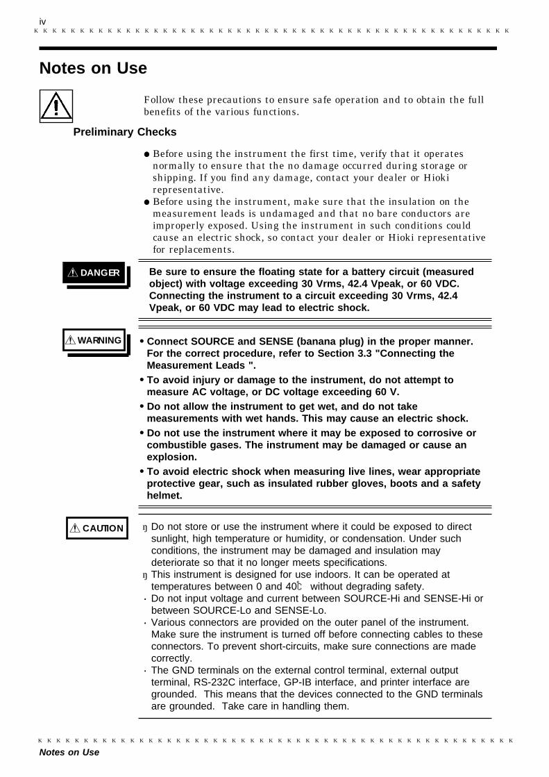
DANGER Be sure to ensure the floating state for a battery circuit (measuredobject) with voltage exceeding 30 Vrms, 42.4 Vpeak, or 60 VDC.Connecting the instrument to a circuit exceeding 30 Vrms, 42.4Vpeak, or 60 VDC may lead to electric shock.
WARNING Connect SOURCE and SENSE (banana plug) in the proper manner.For the correct procedure, refer to Section 3.3 "Connecting theMeasurement Leads ".To avoid injury or damage to the instrument, do not attempt tomeasure AC voltage, or DC voltage exceeding 60 V.Do not allow the instrument to get wet, and do not takemeasurements with wet hands. This may cause an electric shock.Do not use the instrument where it may be exposed to corrosive orcombustible gases. The instrument may be damaged or cause anexplosion.To avoid electric shock when measuring live lines, wear appropriateprotective gear, such as insulated rubber gloves, boots and a safetyhelmet.
CAUTION ・ Do not store or use the instrument where it could be exposed to directsunlight, high temperature or humidity, or condensation. Under suchconditions, the instrument may be damaged and insulation maydeteriorate so that it no longer meets specifications.・ This instrument is designed for use indoors. It can be operated at
temperatures between 0 and 40 without degrading safety.・ Do not input voltage and current between SOURCE-Hi and SENSE-Hi or
between SOURCE-Lo and SENSE-Lo.・ Various connectors are provided on the outer panel of the instrument.
Make sure the instrument is turned off before connecting cables to theseconnectors. To prevent short-circuits, make sure connections are madecorrectly.・ The GND terminals on the external control terminal, external output
terminal, RS-232C interface, GP-IB interface, and printer interface aregrounded. This means that the devices connected to the GND terminalsare grounded. Take care in handling them.
Notes on Use
Follow these precautions to ensure safe operation and to obtain the fullbenefits of the various functions.
Preliminary Checks
Before using the instrument the first time, verify that it operatesnormally to ensure that the no damage occurred during storage orshipping. If you find any damage, contact your dealer or Hiokirepresentative.Before using the instrument, make sure that the insulation on themeasurement leads is undamaged and that no bare conductors areimproperly exposed. Using the instrument in such conditions couldcause an electric shock, so contact your dealer or Hioki representativefor replacements.
v
Chapter Summary
Chapter Summary
This manual consists of the following chapters."Introduction", "Inspection", "Safety Notes", "Notes on Use" include someimportant notes which you should read before using the instrument.
Chapter 1 OverviewOutlines the instrument, and describes the nomenclatures and functionsof the components.
Chapter 2 SpecificationsDescribes general specifications and measurement ranges.
Chapter 3 Preparing for MeasurementDescribes how to turn on the power, connect the measurement leads, andset the power-supply frequency.
Chapter 4 Measurement ProcedureDescribes basic measurement procedures.
Chapter 5 Comparator FunctionDescribes the setup and functions of the comparator.
Chapter 6 External Control Terminal and External Output TerminalDescribes external control via the external-control terminal and external-output terminal.
Chapter 7 RS-232C InterfaceDescribes external control via RS-232C.
Chapter 8 GP-IB Interface (Option)Describes external control via GP-IB.
Chapter 9 Printer Interface (Option)Describes Printer Interface.
Chapter 10 Useful Information and Advanced MeasurementProvides information on the advanced applications of the 3560instrument.
Chapter 11 Maintenance and ServiceDescribes service operations and optional equipment of the 3560instrument.

vi
Chapter Summary

1
1.1 Product Overview
1
2
3
4
5
6
7
8
9
10
11
12
13
14
A
Chapter 1Overview
1.1 Product Overview
The 3560 AC mΩ HiTESTER is a contact-resistance meter capable ofproviding quick and accurate measurements for the contact resistance ofelements such as relays, switches, and connectors, as well as the internalresistance and open-circuit voltage of batteries.This instrument is provided with a comparator function, external outputterminal, external control terminal, and RS-232C interface as standardfeatures. For even higher performance, optional GP-IB and printerinterfaces are available as options.

2
1.2 Features
1.2 Features
(1) AC four-terminal method for accurate measurement of resistance
Thanks to the AC four-terminal method, the 3560 is capable of accurateresistance measurements unaffected by the resistance of leads or bycontact resistance generated between the lead and the measured object.
(2) Measurement of resistance at low power
The 3560 employs a low-power measurement of resistance system thatconforms to global standards. This permits accurate measurement ofcontact resistance without serious damage to the oxide film on thecontact surface.
(3) High-speed measurement and high-speed pass/fail judgment
The 3560 is capable of performing both measurement and pass/failjudgment at high speeds, allowing reduced line tact time. Up to thirtycomparators can be set and one 3560 conducts pass/fail judgmentperformed for various measured objects.
(4) Battery measurement
Since the 3560 simultaneously measures resistance and DC voltage, it iscapable of making a combined pass/fail judgment possible for internalresistance and open-circuit voltage.
(5) Interface
The 3560 comes with an RS-232C interface, external output terminal,and external control terminal as standard features, allowing datacommunications with a computer. The instrument also supports optionalGP-IB and printer interfaces.
(6) Lead options
The 3560 supports options such as clip-type, pin-type, and four-terminalleads, allowing the user to select the most suitable lead for the shape ofthe particular object being measured.
(7) Excellent visibility and ergonomics
The fluorescent character display allows measurements to be read inpoorly-lit areas, and low switch hierarchy allows for easy and intuitiveoperation.

3
1.3 Identification of Controls and Indicators
1
2
3
4
5
6
7
8
9
10
11
12
13
14
A
1
2
3
4
5
6
7
8
9
10
11
12
13
14
A
1.3.1 Fluorescent Character Display Tube
1 2 3 4 5 6
7
89
11
121314
15
10
16
1 REMOTE This indicator lights to indicate control through RS-232C or GP-IBinterfaces.
2 LIMIT OFF This indicator lights to indicate that open-circuit terminal voltage isnot limited to 20 mV.
3 SHIFT This symbol appears when this key is pressed, and disappears whenany other key is pressed.
4 LOCK This indicator lights to indicate that the key lock is active.
5 Buzzer (1) This symbol indicates that the buzzer is enabled.
6 Buzzer (2) This indicator displays the buzzer setting for the selected comparator.
7 AUTO This symbol appears to indicate that the resistance or voltage range isset to auto-range.
8 FMS This indicator displays the sampling rate setting. "F" stands for Fast;"M" stands for Medium; and "S" stands for Slow.
9 HOLD This indicator lights to indicate that the instrument is in hold mode.
10 kΩ/V/mΩ These symbols indicate various instruments.
11 Hi/IN/Lo This symbol indicates comparator operation results in resistancemeasurement mode.
12 PASS/FAIL This symbol displays comparator operation results in resistance andvoltage measurement mode.
13 COMP SET This symbol lights to indicate use of either the comparator function("COMP" is lit) or set ("COMP SET" is lit).
14 Ω・V This symbol indicates either resistance mode ("Ω" is lit) or resistanceand voltage mode ("Ω" is lit)
15 This symbol indicates the comparator number.
16 HIGH/LOW This symbol indicates the upper and lower limits of the comparator.
1.3 Identification of Controls and Indicators

4
1.3 Identification of Controls and Indicators
1.3.2 Front Panel
1 2 3 4 5
6
7
8
9 10 11
12
1314 15
16 17 18
5
1.3 Identification of Controls and Indicators
1
2
3
4
5
6
7
8
9
10
11
12
13
14
A
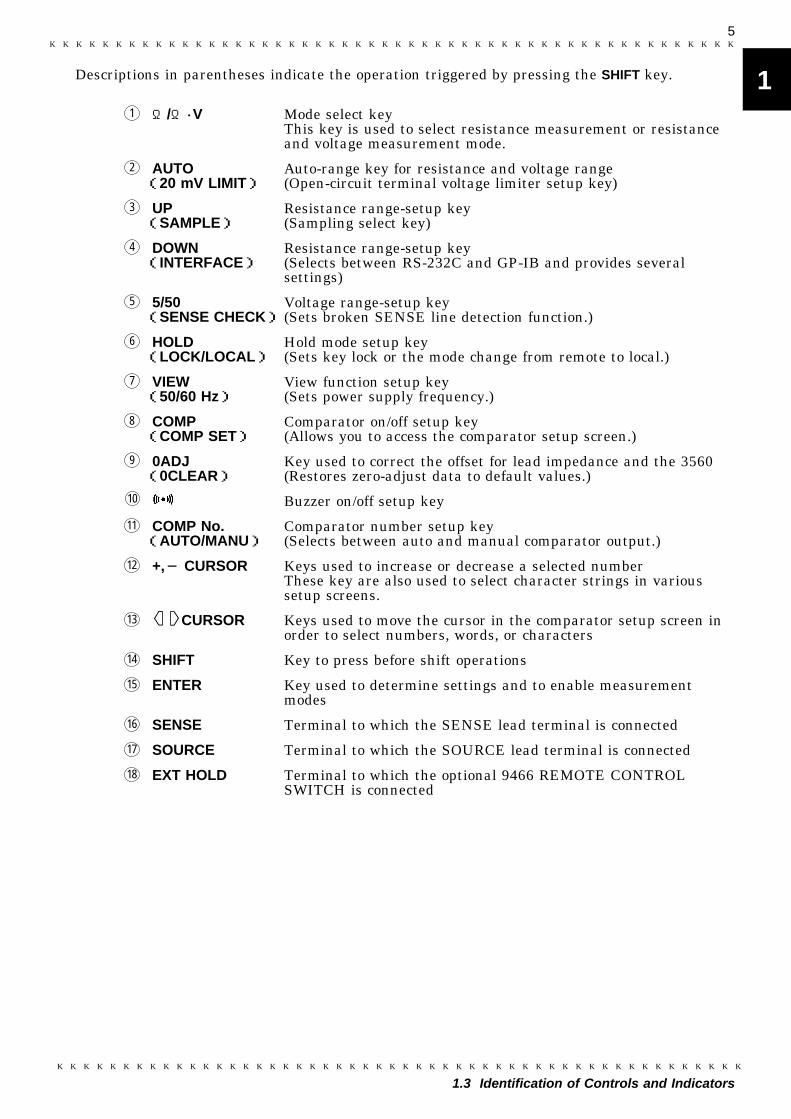
1 Ω/Ω・V Mode select keyThis key is used to select resistance measurement or resistanceand voltage measurement mode.
2 AUTO(20 mV LIMIT)
Auto-range key for resistance and voltage range(Open-circuit terminal voltage limiter setup key)
3 UP(SAMPLE)
Resistance range-setup key(Sampling select key)
4 DOWN(INTERFACE)
Resistance range-setup key(Selects between RS-232C and GP-IB and provides severalsettings)
5 5/50(SENSE CHECK)
Voltage range-setup key(Sets broken SENSE line detection function.)
6 HOLD(LOCK/LOCAL)
Hold mode setup key(Sets key lock or the mode change from remote to local.)
7 VIEW(50/60 Hz)
View function setup key(Sets power supply frequency.)
8 COMP(COMP SET)
Comparator on/off setup key(Allows you to access the comparator setup screen.)
9 0ADJ(0CLEAR)
Key used to correct the offset for lead impedance and the 3560(Restores zero-adjust data to default values.)
10 Buzzer on/off setup key
11 COMP No.(AUTO/MANU)
Comparator number setup key(Selects between auto and manual comparator output.)
12 +, CURSOR Keys used to increase or decrease a selected numberThese key are also used to select character strings in varioussetup screens.
13 CURSOR Keys used to move the cursor in the comparator setup screen inorder to select numbers, words, or characters
14 SHIFT Key to press before shift operations
15 ENTER Key used to determine settings and to enable measurementmodes
16 SENSE Terminal to which the SENSE lead terminal is connected
17 SOURCE Terminal to which the SOURCE lead terminal is connected
18 EXT HOLD Terminal to which the optional 9466 REMOTE CONTROLSWITCH is connected
Descriptions in parentheses indicate the operation triggered by pressing the SHIFT key.

6
1.3 Identification of Controls and Indicators
1.3.3 Rear Panel / Side Panel
1 2 3
4 5 6
7
1 POWER INLET Terminal to which the power cord is connected(built-in fuse type)
2 POWER SWITCH Switch used to switch on power
3 RS-232C INTERFACE RS-232C interface terminal
4 EXTERNAL OUTPUTTERMINAL
Data output terminal
5 EXTERNAL CONTROLTERMINAL
Terminal used for external control of the instrument
6 BLIND PANEL Slot for optional interface instrument
7 STAND (HANDLE) Stand (also used as a handle)

7
2.1 General Specifications
1
2
3
4
5
6
7
8
9
10
11
12
13
14
A
1
2
3
4
5
6
7
8
9
10
11
12
13
14
A
Measurement method Resistance AC four-terminal methodA/D method Σ-Δ method with sample hold functionSampling rate Rated supply frequency:
50 Hz FAST 50 samples/sec 20.0 ms MEDIUM 6.25 samples/sec 160 ms SLOW 1.56 samples/sec 640 ms60 Hz FAST 60 samples/sec 16.7 ms MEDIUM 7.52 samples/sec 133 ms SLOW 1.88 samples/sec 533 ms
Response time(When a non-inductiveresistance is measured)
Rated supply frequency:50 Hz FAST 100 ms MEDIUM 800 ms SLOW 1.92 s60 Hz FAST 84 ms MEDIUM 667 ms SLOW 1.60 sResponse time may be determined by the measured object.
Open-circuit terminalvoltage
20 mVp max. (When limiter is ON)
Input overflow "OF" displayCurrent abnormality "-----" displayComparator mode switch Switchable between AUTO and MANUComparator number 30 setsComparator buzzer [Resistance measurement mode]:
The buzzer sounds if the comparator results is Hi,Lo or IN.[Resistance and voltage measurement mode]:The buzzer sounds if the comparator results is PASS or FAIL.
Hold function Holds the display value.Zero adjust function Revision of induced voltage in circuits and measurement leads.Zero clear function Restores zero-adjust data to default values.View function Displays both the measured value and comparator setting.Buzzer function Turns the buzzer on or off while using the comparator.Broken SENSE linedetection
Detects a broken SENSE line.
Chapter 2Specifications
2.1 General Specifications

8
2.1 General Specifications
External control terminals [CMOS input]Measurement trigger(TRIG), Comparator trigger(MANU),Printer(PRINT), Zero-adjustment(0ADJ), Digital ground(GND), Comparator number selection(COMP0 to COMP4),External power supply terminal(EXT.DCV)
External output terminals [Open collector output] (35 VDC max, 50 mA max.)Comparator results (Hi (FAIL), IN (PASS), Lo (FAIL))*End-of-output conversion signals (EOC) Measurementirregularity signal (NG), Digital ground (GND)*: Words in parentheses indicate output in resistance and
voltage measurement mode.RS-232C I/F StandardGP-IB I/F OptionPrinter I/F Option, Centronics (can be connected the 9203 DIGITAL PRINTER)Operating temperature andhumidity range
0 to 40 (32 to 104 F), 80%RH or less (no condensing)
Storage temperature andhumidity rage
10 to 50 (14 to 122 F), 80%RH or less (no condensing)
Operating temperature and humidity forguaranteed accuracyPeriod of guaranteed accuracy
23±5 (73±9 F), 80%RH or less (no condensing)
1 yearLocation for use Indoor, altitude up to 2000 m (6566 feet)Rated supply voltage 100 V /110 V /120 V /200 V /220 V /240 V AC
(A voltage variation of ±10% is considered for the rated powersupply voltage.), Rated supply frequency: 50/60 Hz
Maximum rated power 30 VAMaximum input voltage 60 VDC max (AC voltage cannot be input.)Dielectric strength 2.3 kVrms for 1 minute / between power supply line (L,N) and
the Protective ground terminal(dielectric strength measured within the inlet)
Dimensions 215W×80H×320D mm(8.46"W×3.15"H×12.6"D) approx.(excluding protrusions)
Mass 2.1 kg (74.1 oz) approx.(not including options)Accessories 9287-10 CLIP TYPE LEAD, Instruction manual,
Basic Instructions, Power cordOptions 9455 PIN TYPE LEAD
9461 PIN TYPE LEAD9467 LARGE CLIP TYPE LEAD9452 CLIP TYPE LEAD9453 FOUR TERMINAL LEAD9466 REMOTE CONTROL SWITCH9454 ZERO ADJUSTMENT BOARD9588 GP-IB INTERFACE9151-02 GP-IB CONNECTOR CABLE (2 m)9151-04 GP-IB CONNECTOR CABLE (4 m)9589 PRINTER INTERFACE9203 DIGITAL PRINTER9425 CONNECTION CABLE (for connecting the 3560 to the 9203/2-meters)9233 RECORDING PAPER (for the 9203/10meters, 10rolls )
Applicable standards EMC: EN 61326:1997+A1:1998+A2:2001+A3:2003 EN 61000-3-2:2000, EN 61000-3-3:1995+A1:2001Safety: EN 61010-1:2001Pollution degree: level 2Effect of radiated radio-frequency electromagnetic field: 4% f.s. at3V/m (resistance measurement)Effect of conducted radio-frequency electromagnetic field: 15% f.s.at 3V (resistance measurement)

9
2.2 Measurement Range
1
2
3
4
5
6
7
8
9
10
11
12
13
14
A
1
2
3
4
5
6
7
8
9
10
11
12
13
14
A
Range Maximumindication Resolution Measurement
currentAccuracy
(6 months)Accuracy(1 year)
30 mΩ 31.000 mΩ 1 μΩ 7.4 mA ±0.5%rdgt.±8 dgt.(3 dgt.)
±0.7%rdgt.±8 dgt.(3 dgt.)300 mΩ 310.00 mΩ 10 μΩ 1 mA
3 Ω 3.1000 Ω 100 μΩ 100 μA
30 Ω 31.000 Ω 1 mΩ 10 μA
300 Ω 310.00 Ω 10 mΩ 5 μA
3 kΩ 3.1000 kΩ 100 mΩ 1.5 μA
Range Maximumindication Resolution Measurement
currentAccuracy
(6 months)Accuracy(1 year)
30 mΩ 31.00 mΩ 10 μΩ 7.4 mA ±0.5%rdgt.±8 dgt.
±0.7%rdgt.±8 dgt.
300 mΩ 310.0 mΩ 100 μΩ 1 mA ±0.5%rdgt.±6 dgt.
±0.7%rdgt.±6 dgt.3 Ω 3.100 Ω 1 mΩ 100 μA
30 Ω 31.00 Ω 10 mΩ 10 μA
300 Ω 310.0 Ω 100 mΩ 5 μA
3 kΩ 3.100 kΩ 1 Ω 1.5 μA
Range(V)
Maximumindication
(V)
Measurementcurrent
(V)
Accuracy(6 months)
Accuracy(1 year)
5 ±5.0000 100 μ ±0.05%rdgt.±5dgt.(3dgt.)【5 dgt.】
±0.07%rdgt.±5dgt.(3dgt.)【5 dgt.】50 ±50.000 1 m
2.2 Measurement Range
Resistance measurement
Sampling rate: SLOW, MEDIUMTemperature coefficient: (±0.05%rdg.±0.8 dgt.)/
* If the sampling rate is set to MEDIUM, add ( ) to the digit accuracyerror.
Sampling rate: FASTTemperature coefficient: 30 mΩrange (±0.05%rdg.±0.8 dgt.)/
: the other range (±0.05%rdg.±0.6 dgt.)/
Measurement current accuracy: ±10%Measurement current frequency Accuracy: 1 kHz±0.2 Hz
Voltage measurement
Sampling rate: SLOW, MEDIUM, FASTTemperature coefficient: (±0.005%rdg.±0.5 dgt.)/
* If the sampling rate is set to MEDIUM, add ( ) to the digit accuracyerror.
* If the sampling rate is set to FAST, add【 】to the digit accuracy error.

10
2.3 External Dimensions
215±5
275±5
14±
180±
5
320±5
2.3 External Dimensions
11
3.1 Mounting the Interface
1
2
3
4
5
6
7
8
9
10
11
12
13
14
A
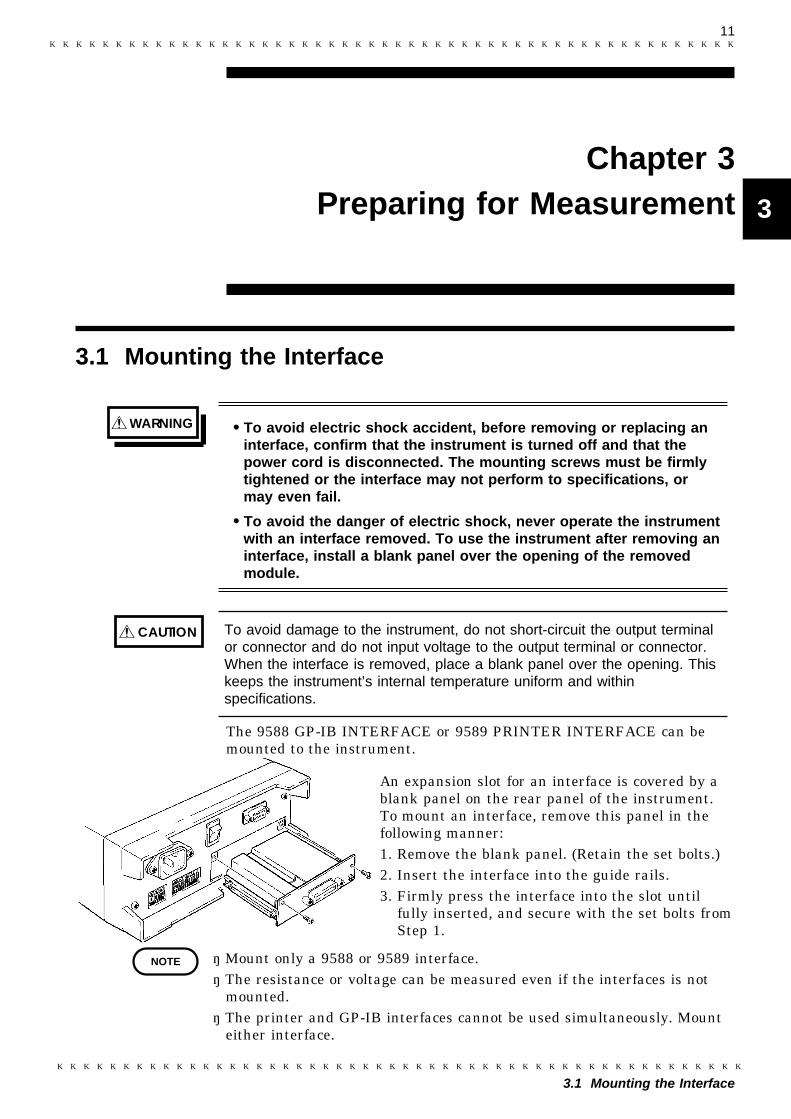
WARNING To avoid electric shock accident, before removing or replacing aninterface, confirm that the instrument is turned off and that thepower cord is disconnected. The mounting screws must be firmlytightened or the interface may not perform to specifications, ormay even fail.
To avoid the danger of electric shock, never operate the instrumentwith an interface removed. To use the instrument after removing aninterface, install a blank panel over the opening of the removedmodule.
CAUTION To avoid damage to the instrument, do not short-circuit the output terminalor connector and do not input voltage to the output terminal or connector.When the interface is removed, place a blank panel over the opening. Thiskeeps the instrument’s internal temperature uniform and withinspecifications.
NOTE
Chapter 3Preparing for Measurement
3.1 Mounting the Interface
The 9588 GP-IB INTERFACE or 9589 PRINTER INTERFACE can bemounted to the instrument.
An expansion slot for an interface is covered by ablank panel on the rear panel of the instrument.To mount an interface, remove this panel in thefollowing manner:1. Remove the blank panel. (Retain the set bolts.)2. Insert the interface into the guide rails.3. Firmly press the interface into the slot until
fully inserted, and secure with the set bolts fromStep 1.
・ Mount only a 9588 or 9589 interface.・ The resistance or voltage can be measured even if the interfaces is not
mounted.・ The printer and GP-IB interfaces cannot be used simultaneously. Mount
either interface.
12
3.2 Connecting the Power Cord
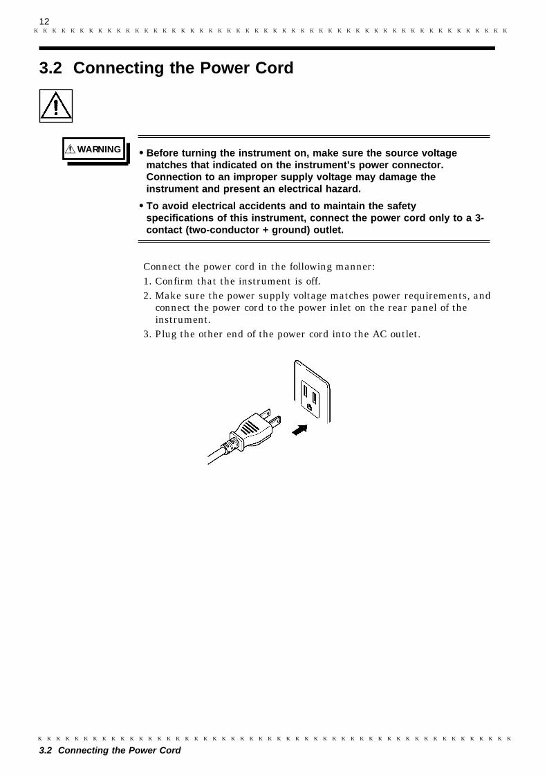
WARNING Before turning the instrument on, make sure the source voltagematches that indicated on the instrument’s power connector.Connection to an improper supply voltage may damage theinstrument and present an electrical hazard.
To avoid electrical accidents and to maintain the safetyspecifications of this instrument, connect the power cord only to a 3-contact (two-conductor + ground) outlet.
3.2 Connecting the Power Cord
Connect the power cord in the following manner:1. Confirm that the instrument is off.2. Make sure the power supply voltage matches power requirements, and
connect the power cord to the power inlet on the rear panel of theinstrument.
3. Plug the other end of the power cord into the AC outlet.
13
3.3 Connecting the Measurement Leads
1
2
3
4
5
6
7
8
9
10
11
12
13
14
A
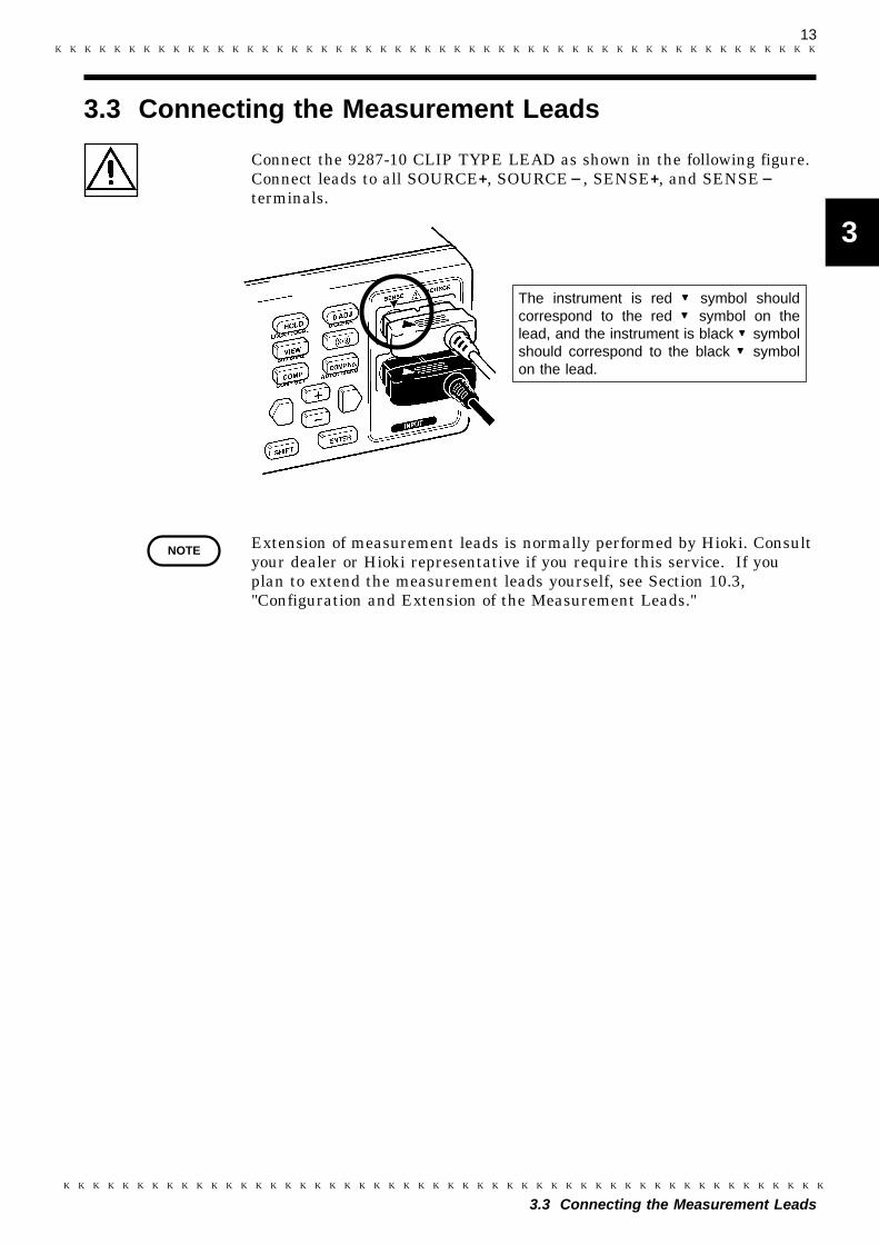
The instrument is red symbol shouldcorrespond to the red symbol on thelead, and the instrument is black symbolshould correspond to the black symbolon the lead.
NOTE
3.3 Connecting the Measurement Leads
Connect the 9287-10 CLIP TYPE LEAD as shown in the following figure.Connect leads to all SOURCE+, SOURCE , SENSE+, and SENSEterminals.
Extension of measurement leads is normally performed by Hioki. Consultyour dealer or Hioki representative if you require this service. If youplan to extend the measurement leads yourself, see Section 10.3,"Configuration and Extension of the Measurement Leads."
14
3.4 Powering On/Off
NOTE
3.4 Powering On/Off
Powering ON1. Turn on the rear panel POWER switch (set the switch to the position
marked as "1.") The initial screen appears in the display.2. A diagnostic self-test runs to test ROM and RAM devices for errors.
Error messages are displayed for defective items. No error messagesare displayed for passed items. For information on error messages, seeSection 11.1 "Message Code Table."
3. If the self-test finishes without errors, the instrument enters normalmeasurement mode.
Powering OFFTurn off the rear panel POWER switch (set switch to the position marked"0.") All measurement parameters are saved.
After switching on the instrument, allow it to warm up for at least 60min before performing measurements.
15
3.5 Setting the Power Supply Frequency
1
2
3
4
5
6
7
8
9
10
11
12
13
14
A
Blinking
NOTE
3.5 Setting the Power Supply Frequency
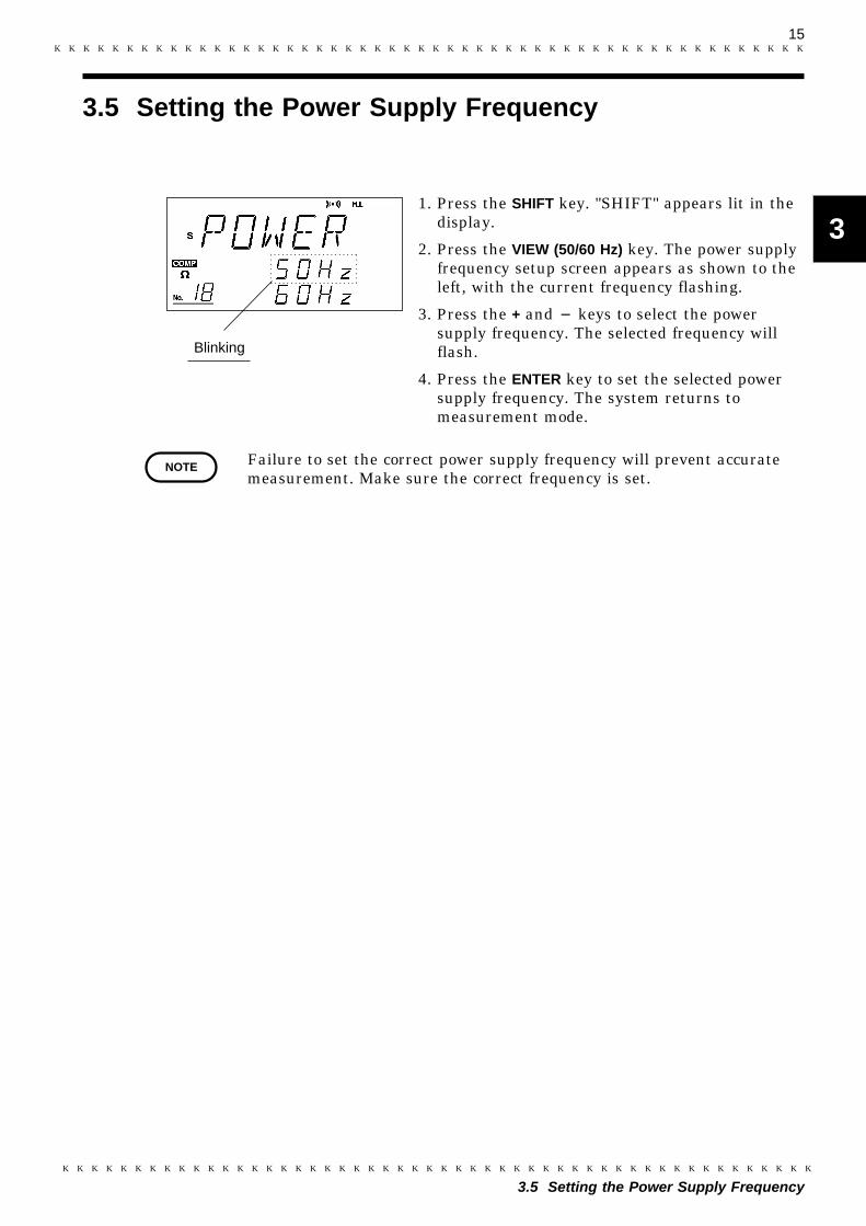
1. Press the SHIFT key. "SHIFT" appears lit in thedisplay.
2. Press the VIEW (50/60 Hz) key. The power supplyfrequency setup screen appears as shown to theleft, with the current frequency flashing.
3. Press the + and keys to select the powersupply frequency. The selected frequency willflash.
4. Press the ENTER key to set the selected powersupply frequency. The system returns tomeasurement mode.
Failure to set the correct power supply frequency will prevent accuratemeasurement. Make sure the correct frequency is set.

16
3.6 Instrument Handle
CAUTION When using the handle as a stand for the device, do not press down toohard on the device as this can damage the handle.
3.6 Instrument Handle
The handle can be used as a stand. Pull both ends of the handle outwardto release it and rotate it to the desired position. Then, push the handleinward to lock it in place. The handle can be locked at interval of 22.5degrees.
17
1
2
3
4
5
6
7
8
9
10
11
12
13
14
A
Setting the comparator functions
Selecting the measurement mode
Setting the measurement range
Advanced setting
Starting measurement
Executing zero adjust
Sampling rate
Hold
Lead Line break check
Zero clear
Key lock
Local
Buzzer
Voltage limiter
Preparing for Measurement
Chapter 4Measurement Procedure
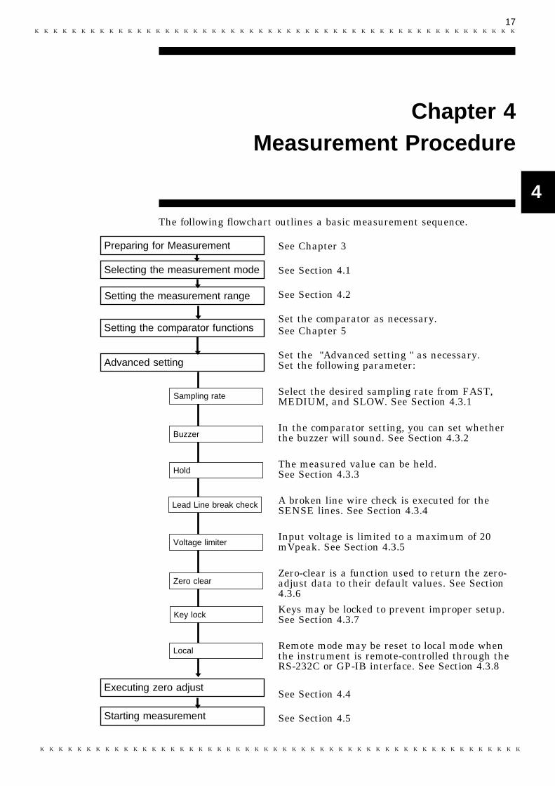
The following flowchart outlines a basic measurement sequence.
See Chapter 3
See Section 4.1
See Section 4.2
Set the comparator as necessary.See Chapter 5
Set the "Advanced setting " as necessary.Set the following parameter:
Select the desired sampling rate from FAST,MEDIUM, and SLOW. See Section 4.3.1
In the comparator setting, you can set whetherthe buzzer will sound. See Section 4.3.2
The measured value can be held.See Section 4.3.3
A broken line wire check is executed for theSENSE lines. See Section 4.3.4
Input voltage is limited to a maximum of 20mVpeak. See Section 4.3.5
Zero-clear is a function used to return the zero-adjust data to their default values. See Section4.3.6
Keys may be locked to prevent improper setup.See Section 4.3.7
Remote mode may be reset to local mode whenthe instrument is remote-controlled through theRS-232C or GP-IB interface. See Section 4.3.8
See Section 4.4
See Section 4.5
18
4.1 Selecting the Measurement Mode
4.1 Selecting the Measurement Mode
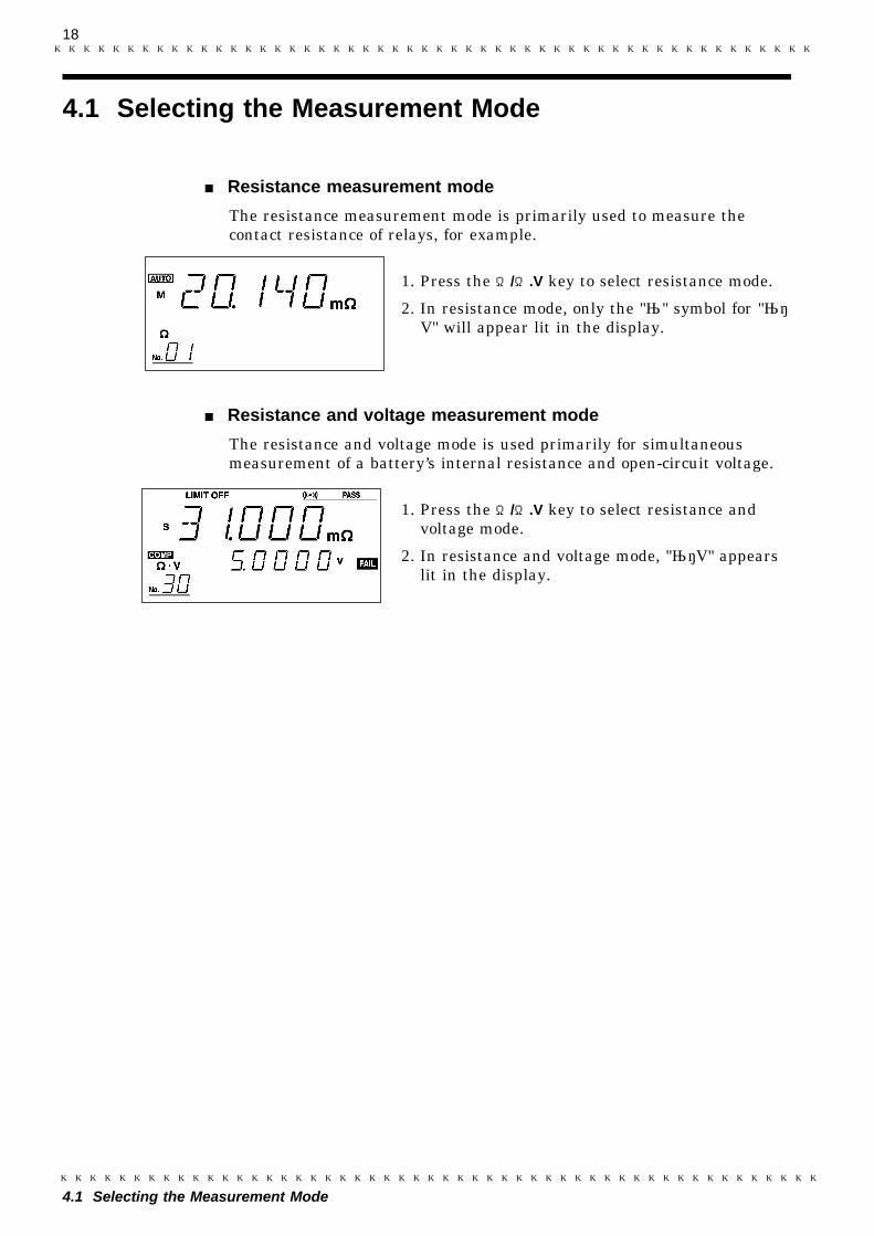
Resistance measurement mode
The resistance measurement mode is primarily used to measure thecontact resistance of relays, for example.
1. Press the Ω/Ω.V key to select resistance mode.
2. In resistance mode, only the "Ω" symbol for "Ω・V" will appear lit in the display.
Resistance and voltage measurement mode
The resistance and voltage mode is used primarily for simultaneousmeasurement of a battery’s internal resistance and open-circuit voltage.
1. Press the Ω/Ω.V key to select resistance andvoltage mode.
2. In resistance and voltage mode, "Ω・V" appearslit in the display.
19
4.2 Setting the Measurement Range
1
2
3
4
5
6
7
8
9
10
11
12
13
14
A
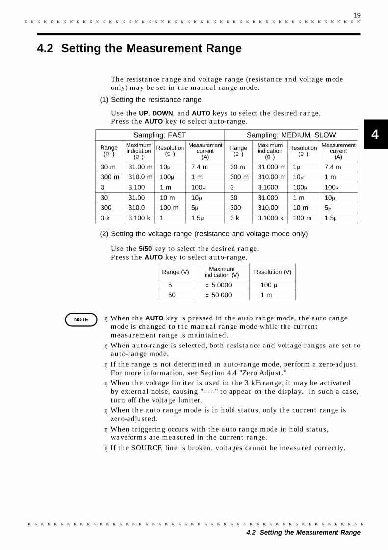
Sampling: FAST Sampling: MEDIUM, SLOW
Range(Ω)
Maximumindication
(Ω)
Resolution(Ω)
Measurementcurrent
(A)
Range(Ω)
Maximumindication
(Ω)
Resolution(Ω)
Measurementcurrent
(A)
30 m 31.00 m 10μ 7.4 m 30 m 31.000 m 1μ 7.4 m
300 m 310.0 m 100μ 1 m 300 m 310.00 m 10μ 1 m
3 3.100 1 m 100μ 3 3.1000 100μ 100μ
30 31.00 10 m 10μ 30 31.000 1 m 10μ
300 310.0 100 m 5μ 300 310.00 10 m 5μ
3 k 3.100 k 1 1.5μ 3 k 3.1000 k 100 m 1.5μ
Range (V) Maximumindication (V) Resolution (V)
5 ±5.0000 100 μ
50 ±50.000 1 m
NOTE
4.2 Setting the Measurement Range
The resistance range and voltage range (resistance and voltage modeonly) may be set in the manual range mode.
(1) Setting the resistance range
Use the UP, DOWN, and AUTO keys to select the desired range.Press the AUTO key to select auto-range.
(2) Setting the voltage range (resistance and voltage mode only)
Use the 5/50 key to select the desired range.Press the AUTO key to select auto-range.
・ When the AUTO key is pressed in the auto range mode, the auto rangemode is changed to the manual range mode while the currentmeasurement range is maintained.・ When auto-range is selected, both resistance and voltage ranges are set to
auto-range mode.・ If the range is not determined in auto-range mode, perform a zero-adjust.
For more information, see Section 4.4 "Zero Adjust."・ When the voltage limiter is used in the 3 kΩrange, it may be activated
by external noise, causing "-----" to appear on the display. In such a case,turn off the voltage limiter.・ When the auto range mode is in hold status, only the current range is
zero-adjusted.・ When triggering occurs with the auto range mode in hold status,
waveforms are measured in the current range.・ If the SOURCE line is broken, voltages cannot be measured correctly.
20
4.3 Advanced Setting
4.3.1 Sampling Rate
NOTE
4.3.2 Buzzer
Buzzer: ON
Buzzer: OFF
NOTE
4.3 Advanced Setting
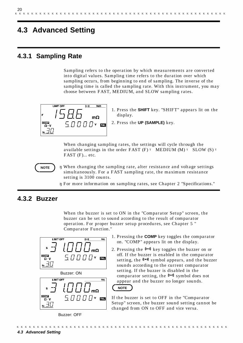
Sampling refers to the operation by which measurements are convertedinto digital values. Sampling time refers to the duration over whichsampling occurs, from beginning to end of sampling. The inverse of thesampling time is called the sampling rate. With this instrument, you maychoose between FAST, MEDIUM, and SLOW sampling rates.
1. Press the SHIFT key. "SHIFT" appears lit on thedisplay.
2. Press the UP (SAMPLE) key.
When changing sampling rates, the settings will cycle through theavailable settings in the order FAST (F) → MEDIUM (M) → SLOW (S) →FAST (F)... etc.
・ When changing the sampling rate, alter resistance and voltage settingssimultaneously. For a FAST sampling rate, the maximum resistancesetting is 3100 counts.・ For more information on sampling rates, see Chapter 2 "Specifications."
When the buzzer is set to ON in the "Comparator Setup" screen, thebuzzer can be set to sound according to the result of comparatoroperation. For proper buzzer setup procedures, see Chapter 5 "Comparator Function."
1. Pressing the COMP key toggles the comparatoron. "COMP" appears lit on the display.
2. Pressing the key toggles the buzzer on oroff. If the buzzer is enabled in the comparatorsetting, the symbol appears, and the buzzersounds according to the current comparatorsetting. If the buzzer is disabled in thecomparator setting, the symbol does notappear and the buzzer no longer sounds.
If the buzzer is set to OFF in the "ComparatorSetup" screen, the buzzer sound setting cannot bechanged from ON to OFF and vice versa.

21
4.3 Advanced Setting
1
2
3
4
5
6
7
8
9
10
11
12
13
14
A
4.3.3 Hold
NOTE
The measured value can be held. The hold function may be used with thetrigger function (available via the external control terminal). For moreinformation on the trigger function, see Section 6.3.1 "External ControlTerminal"
1. Pressing the HOLD key displays "HOLD" andholds the measured value.
2. Press the HOLD key again to cancel this mode.
・ When the range is changed in hold status, the held data are erased.・ When the measurement mode is changed in hold status, the displayed
voltage may not be output to the RS-232C and GP-IB, or irrelevantvalues may be displayed on the screen. Before changing themeasurement mode, perform the setting again.
Using the EXT. HOLD terminals, the same effect as the hold key can beobtained.
1. Remove the lead from battery to be tested.
2. Insert the mini-plug of the 9466 to theEXT.HOLD terminal.
3. Press the 9466 switch for at least 200 ms toobtain the effect of pressing the HOLD key.The "hold" indication appears in the display,and the measurement values are held.
4. To release the hold condition, press the 9466switch for at least 200 ms again or press theHOLD key.

22
4.3 Advanced Setting
9466
Spiral tube (small)
Spiral tube (large)
NOTE
9466 REMOTE CONTROL SWITCH
The 9465 PIN TYPE LEAD and 9466 REMOTE CONTROL SWITCH canbe combined as shown below. (The 9455 PIN TYPE LEAD and 9461 PINTYPE LEAD can be also combined with the 9466.)Connect the switch to the probe of the lead, and join the two cables usingthe supplied spiral tube.
・ Do not insert or remove the mini-plug while the lead is connected to thebatteries. Before replacing the plug, always remove the lead from thebatteries.・ If the spiral tube has a sharp edge at the end, round it with scissors to
prevent possible injury.
23
4.3 Advanced Setting
4.3.4 Lead Line Break Check (Imperfect Contact Check)
NOTE
NOTE
SOURCE line break check
The 3560 measures resistance using the AC constant-current system.With this method, an AC constant current is unlikely to be supplied dueto a broken SOURCE line or the resistance of the measurement object.Since using normal measurement procedures in such circumstance willproduce incorrect resistance measurements, the system checks theSOURCE line for breaks. If a break is detected, "-----"appears in themeasured value display field, and the associated signal is output to theexternal output terminal. For external output terminal details, seeSection 6.3.2 "External Output Terminal."
The SOURCE line break check cannot be disabled.
SENSE line break check
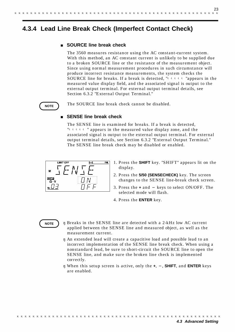
The SENSE line is examined for breaks. If a break is detected,"-----" appears in the measured value display zone, and theassociated signal is output to the external output terminal. For externaloutput terminal details, see Section 6.3.2 "External Output Terminal."The SENSE line break check may be disabled or enabled.
1. Press the SHIFT key. "SHIFT" appears lit on thedisplay.
2. Press the 5/50 (SENSECHECK) key. The screenchanges to the SENSE line-break check screen.
3. Press the + and keys to select ON/OFF. Theselected mode will flash.
4. Press the ENTER key.
・ Breaks in the SENSE line are detected with a 2-kHz low AC currentapplied between the SENSE line and measured object, as well as themeasurement current.・ An extended lead will create a capacitive load and possible lead to an
incorrect implementation of the SENSE line break check. When using anonstandard lead, be sure to short-circuit the SOURCE line to open theSENSE line, and make sure the broken line check is implementedcorrectly.・ When this setup screen is active, only the +, , SHIFT, and ENTER keys
are enabled.
24
4.3 Advanced Setting
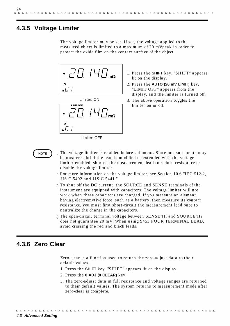
4.3.5 Voltage Limiter
Limiter: OFF
Limiter: ON
NOTE
4.3.6 Zero Clear
The voltage limiter may be set. If set, the voltage applied to themeasured object is limited to a maximum of 20 mVpeak in order toprotect the oxide film on the contact surface of the object.
1. Press the SHIFT key. "SHIFT" appearslit on the display.
2. Press the AUTO (20 mV LIMIT) key."LIMIT OFF" appears from thedisplay, and the limiter is turned off.
3. The above operation toggles thelimiter on or off.
・ The voltage limiter is enabled before shipment. Since measurements maybe unsuccessful if the lead is modified or extended with the voltagelimiter enabled, shorten the measurement lead to reduce resistance ordisable the voltage limiter.・ For more information on the voltage limiter, see Section 10.6 "IEC 512-2,
JIS C 5402 and JIS C 5441."・ To shut off the DC current, the SOURCE and SENSE terminals of the
instrument are equipped with capacitors. The voltage limiter will notwork when these capacitors are charged. If you measure an elementhaving electromotive force, such as a battery, then measure its contactresistance, you must first short-circuit the measurement lead once toneutralize the charge in the capacitors.・ The open-circuit terminal voltage between SENSE-Hi and SOURCE-Hi
does not guarantee 20 mV. When using 9453 FOUR TERMINAL LEAD,avoid crossing the red and black leads.
Zero-clear is a function used to return the zero-adjust data to theirdefault values.1. Press the SHIFT key. "SHIFT" appears lit on the display.2. Press the 0 ADJ (0 CLEAR) key.3. The zero-adjust data in full resistance and voltage ranges are returned
to their default values. The system returns to measurement mode afterzero-clear is complete.

25
4.3 Advanced Setting
4.3.7 Key Lock
Key lock active
Key lock canceled
4.3.8 Local
Remote mode active
Remote mode canceled
NOTE
Keys may be locked to prevent improper setup.
Set the key lock function in thefollowing manner:
1. Press the SHIFT key. "SHIFT"appears lit on the display.
2. Press the HOLD (LOCK/LOCAL) key."LOCK" appears in the display toindicate that keys are locked.
Cancel the key lock function in thefollowing manner:
1. Press the SHIFT key. "SHIFT"appears lit on the display.
2. Press the HOLD (LOCK/LOCAL) key."LOCK" disappears from the display,and the key lock is canceled.
When the instrument is remote-controlled through an RS-232C or GP-IBinterface, the remote mode may be changed to local mode. When localmode is active, manual operations are available, including key operation.Local mode does not affect the key lock function. For information onturning the key lock function on and off, see Section 4.3.7 "Key Lock."
1. Press the SHIFT key. "SHIFT" appearslit on the display.
2. Press the HOLD (LOCK/LOCAL) key."REMOTE" disappears from thedisplay, and the REMOTE is canceled.
The remote mode can not be enabled bythe key operations.
26
4.4 Zero Adjust
Contacts with SENSE
9453 9287-10
9467
9452
9465Right connection
Wrong connection
Contacts with SOURCE
Distance between battery terminals to be measured
9461
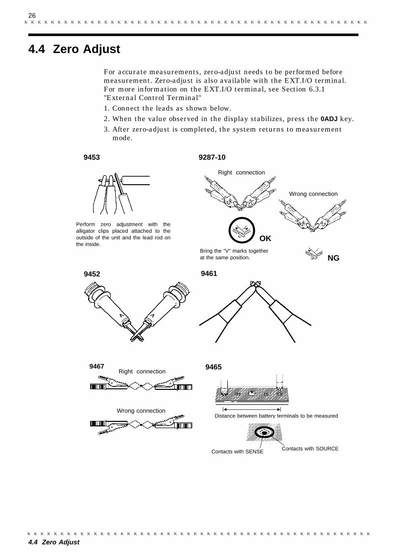
Perform zero adjustment with thealligator clips placed attached to theoutside of the unit and the lead rod onthe inside.
Bring the "V" marks togetherat the same position.
Right connection
Wrong connection
OK
NG
4.4 Zero Adjust
For accurate measurements, zero-adjust needs to be performed beforemeasurement. Zero-adjust is also available with the EXT.I/O terminal.For more information on the EXT.I/O terminal, see Section 6.3.1"External Control Terminal"1. Connect the leads as shown below.2. When the value observed in the display stabilizes, press the 0ADJ key.3. After zero-adjust is completed, the system returns to measurement
mode.
27
4.4 Zero Adjust
NOTE ・ To make a zero adjustment of the 9453, turn off SENSE CHECK.Following the adjustment, SENSE CHECK may be turned on.・ The zero-adjust can be used for up to 2400 counts in measuring
resistance (240 counts for FAST sampling rate) and up to 3400 counts inmeasuring voltage. If an attempt is made to use the zero-adjust beyondthese limits, "ERR-1" appears in the display to prevent further zero-adjust operations. Perform a zero-adjust whenever you change samplingrates.・ The voltage is input to the 3560 for measurement. If the voltage input is
3400 counts or more at zero adjustment, "ERR-1" appears and the zeroadjustment is invalidated even in the resistance measurement mode.・ The value determined upon zero clearing is a reference for the possible
zero adjustment range.・ Whenever the sampling rate is changed, a zero adjustment should be
made.・ For 9455 PIN TYPE LEAD, first conduct the zero-adjust for 9287-10
CLIP TYPE LEAD, then replace the 9287-10 leads with 9455 PIN TYPELEAD and conduct a zero-adjust for the 9455 leads.・ Zero adjustment can also be performed by the 9461 when the 9454 ZERO
ADJUSTMENT BOARD is used.・ When the zero adjustment is made in the auto range mode, it is applied
to the entire range.・ When the system is put in the HOLD mode while the zero adjustment is
being made in the auto range mode, "ERR-1" appears. In this case, cancelthe hold status and execute the zero adjust again.・ When the system is in HOLD mode, the currently displayed value is zero-
adjusted.

28
4.5 Starting Measurement
DANGER ・ Be sure to ensure the floating state for a battery circuit (measuredobject) with voltage exceeding 30 Vrms, 42.4 Vpeak, or 60 VDC.Connecting the instrument to a circuit exceeding 30 Vrms, 42.4Vpeak, or 60 VDC may lead to electric shock.
・ To avoid electrical shock, be careful to avoid shorting live lineswith the measurement leads.
・ Do not measure the voltage of the voltage generator, as doing sowill cause an AC voltage to be applied to the output terminal of thevoltage generator, resulting in a hazard.
・ When a high-voltage battery has been measured and a low-voltagebattery is to be measured, short-circuit the measurement lead todischarge the DC component cutoff capacitor of the 3560.Otherwise, an overvoltage will be applied to the battery.
9465
9452
9287-10
Measurement of resistance
Measurement of battery internal resistance Measurement of relay contact resistance
Rx
When clipping a thin lineClip the line at the tip,serrated part of the jaws.
When clipping a thick line(Clip the line at the deep,non-serrated part of the jaws.)
NOTE
4.5 Starting Measurement
Connect the lead to the measured object and read the measured value.
・ The value displayed may fluctuate if equipment generating magneticfields is located near the 3560, such as electric motors. If fluctuations areobserved, install the instrument in a location at a distance from theequipment.・ Objects having inductance of 5 μH or greater may produce incorrect
measurements.・ Do not pile the 3560 instruments for measurement.・ Note that if the tested object is placed on the instrument or close to the
indicator, measurements may fluctuate due to generated noise.
29
4.5 Starting Measurement
Resistancerange(Ω)
Lead resistanceand contactresistance
SENSE line break check / Voltage limiter
OFF/ON(Ω)
OFF/ON(Ω)
ON/OFF(Ω)
ON/OFF(Ω)
30 m RC1+RL+RC2RC2
1.4900 m
400 m400 m
1.4300 m
400 m300 m
300 m RC1+RL+RC2RC2
137.5
55
1313
53.3
3 RC1+RL+RC2RC2
12576
5555
13034
5534
30 RC1+RL+RC2RC2
990760
260260
990333
260200
300 RC1+RL+RC2RC2
2.3 k1.5 k
890890
2.3 k640
890520
3 k RC1+RL+RC2RC2
8.7 k5.1 k
3.9 k3.9 k
8.7 k1.9 k
3.9 k330
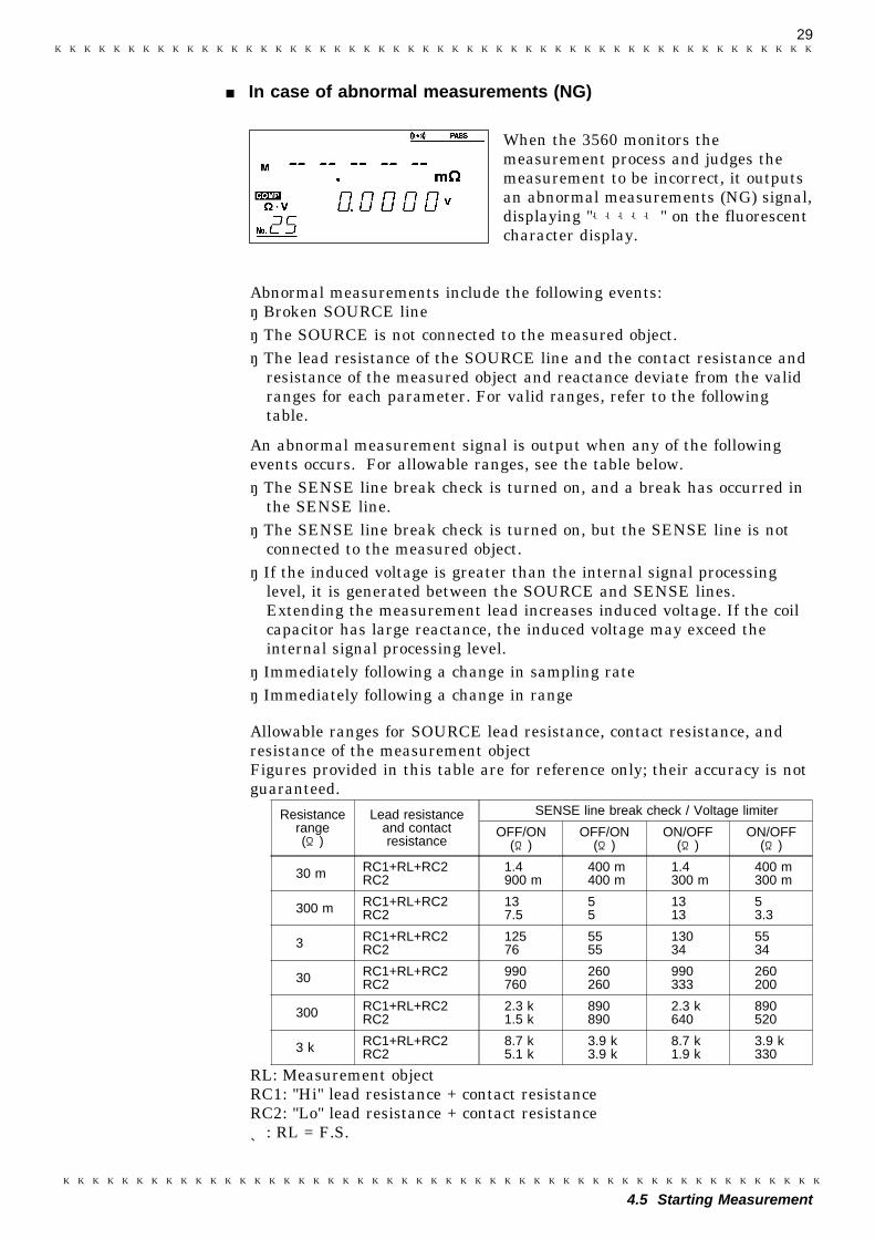
In case of abnormal measurements (NG)
When the 3560 monitors themeasurement process and judges themeasurement to be incorrect, it outputsan abnormal measurements (NG) signal,displaying "-----" on the fluorescentcharacter display.
Abnormal measurements include the following events:・ Broken SOURCE line・ The SOURCE is not connected to the measured object.・ The lead resistance of the SOURCE line and the contact resistance and
resistance of the measured object and reactance deviate from the validranges for each parameter. For valid ranges, refer to the followingtable.
An abnormal measurement signal is output when any of the followingevents occurs. For allowable ranges, see the table below.・ The SENSE line break check is turned on, and a break has occurred in
the SENSE line.・ The SENSE line break check is turned on, but the SENSE line is not
connected to the measured object.・ If the induced voltage is greater than the internal signal processing
level, it is generated between the SOURCE and SENSE lines.Extending the measurement lead increases induced voltage. If the coilcapacitor has large reactance, the induced voltage may exceed theinternal signal processing level.
・ Immediately following a change in sampling rate・ Immediately following a change in range
Allowable ranges for SOURCE lead resistance, contact resistance, andresistance of the measurement objectFigures provided in this table are for reference only; their accuracy is notguaranteed.
RL: Measurement objectRC1: "Hi" lead resistance + contact resistanceRC2: "Lo" lead resistance + contact resistance*: RL = F.S.

30
4.5 Starting Measurement
31
1
2
3
4
5
6
7
8
9
10
11
12
13
14
A
The on/off status for the buzzer can be changed in thecomparator setting.
Setting the buzzer mode
Switching on/off the comparator
Setting the comparator functions
Setting the comparator number
Setting the resistance range
Setting the resistance value
Setting the voltage range
Setting the voltage value
Setting the buzzer mode
See Section 5.2
Setting the comparator number
Setting the resistance range
See Section 5.1
See Section 5.3
See Section 5.4
See Section 5.5
See Section 5.6
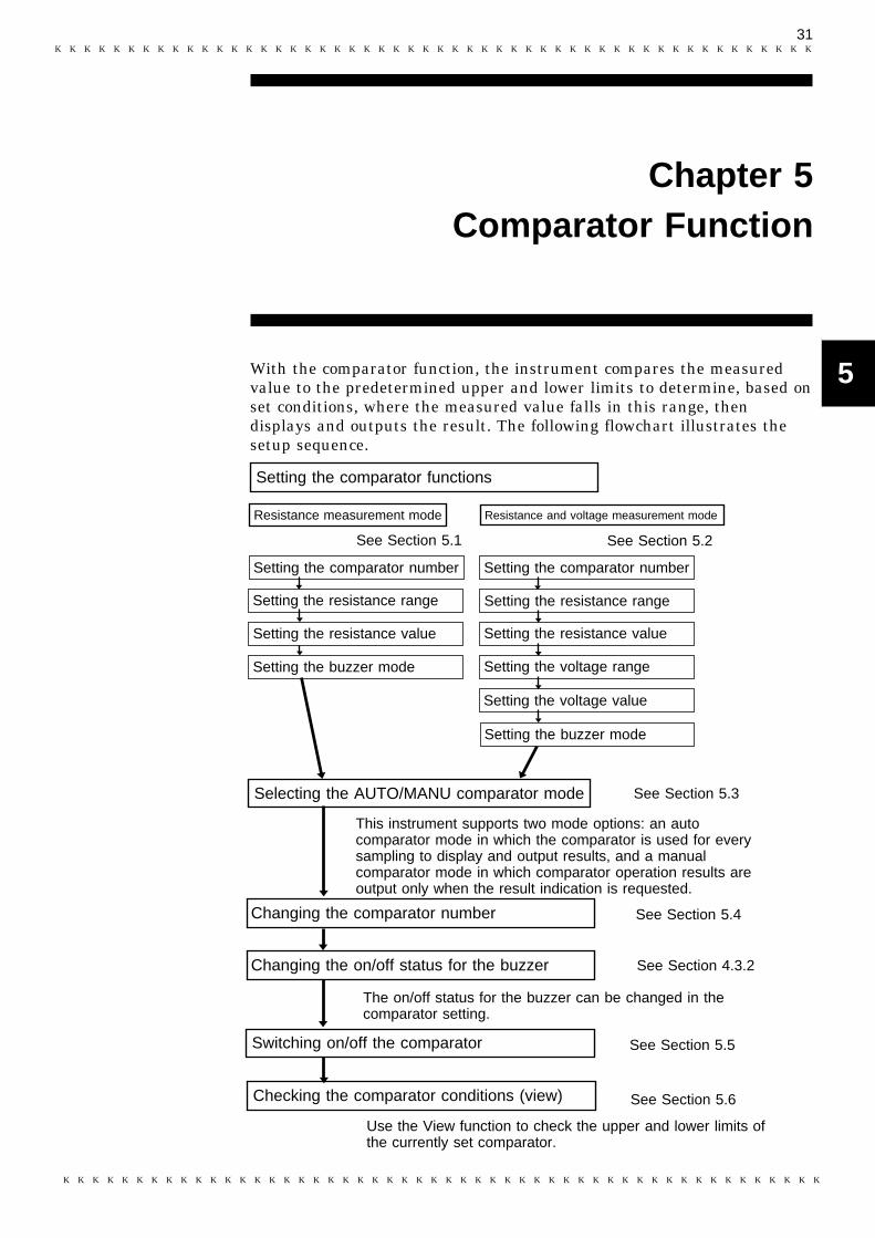
Resistance measurement mode
This instrument supports two mode options: an autocomparator mode in which the comparator is used for everysampling to display and output results, and a manualcomparator mode in which comparator operation results areoutput only when the result indication is requested.
Resistance and voltage measurement mode
Changing the comparator number
Setting the resistance value
Selecting the AUTO/MANU comparator mode
Use the View function to check the upper and lower limits ofthe currently set comparator.
Changing the on/off status for the buzzer See Section 4.3.2
Checking the comparator conditions (view)
Chapter 5Comparator Function
With the comparator function, the instrument compares the measuredvalue to the predetermined upper and lower limits to determine, based onset conditions, where the measured value falls in this range, thendisplays and outputs the result. The following flowchart illustrates thesetup sequence.

32
5.1 Resistance Measurement Mode
The comparator number blinks.
NOTE
5.1 Resistance Measurement Mode
(1) Setting start
1. Press the SHIFT key. "SHIFT" appears lit in thedisplay.
2. Press the COMP (COMP SET) key. The displayswitches to the comparator setup screen.
3. Press the Ω/Ω・V key to select resistance mode.In resistance mode, the screen displays onlythe "Ω" symbol of "Ω・V" as lit.
(2) Setting the comparator numberOn the comparator setup screen, "COMP SET" islit and the comparator number flashes.Use the + and keys to select the desiredcomparator number. You may select numbers inthe range from 01 to 30.
(3) Setting the resistance range
1. Use the (cursor right move) key to select theresistance range setup field.
2. Use the + and keys to set the resistancerange. Select a value within the range 30 mΩto 3 kΩ.
(4) Setting the resistance value
1. Use the (cursor right move) key to select theresistance upper limit setup field.
2. Use the +, , and (cursor left and rightmove) keys to set the upper resistance. Selectvalues in the effective range 0 to 31000.
3. Set the resistance lower limit.
Set these values so that the resistance lower limit is not higher than theresistance upper limit. If the values set violate this rule, the instrumentwill regard the smaller resistance as the lower limit and larger resistanceas the upper limit and execute the comparator function. Determine allfive digits for each limit value. If the sampling rate is set to FAST, thecomparator function is executed by rounding down the lowest digit. Auto-range cannot be selected.

33
5.1 Resistance Measurement Mode
1
2
3
4
5
6
7
8
9
10
11
12
13
14
A
OFF
The buzzer sounds at Hi The buzzer sounds at Hi or Lo.
(5) Setting the buzzer mode
1. Use the (cursor right move) key to select thelast digit of the resistance lower limit setupfield.
2. Press the (cursor right move) key again todisplay the buzzer setup screen.
3. Use the + and keys to set the buzzer. Selecta mode from three available options: "OFF","IN", "HiLo."
(6) Setting end
Press the ENTER key to exit comparator setup. Thesystem returns to the measurement screen.When the is pressed, the screen changes to "(2)Comparator number setup." The next comparatorscan then be set continuously.
34
5.2 Resistance and Voltage Measurement Mode
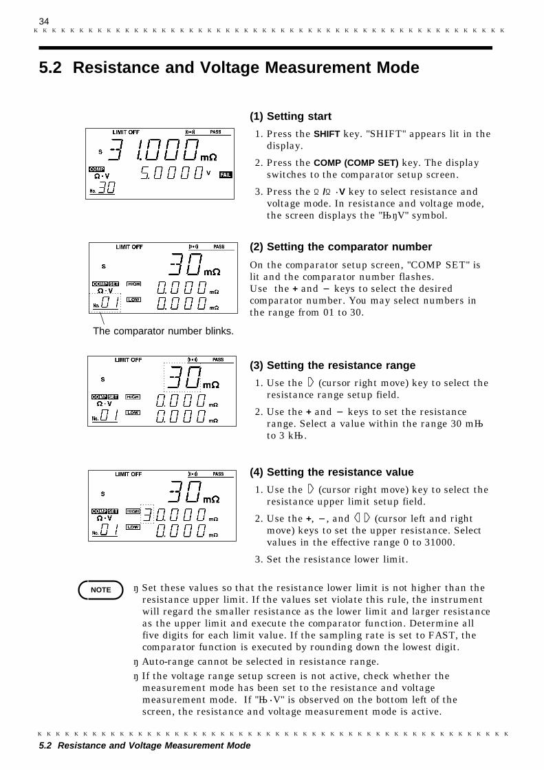
The comparator number blinks.
NOTE
5.2 Resistance and Voltage Measurement Mode
(1) Setting start
1. Press the SHIFT key. "SHIFT" appears lit in thedisplay.
2. Press the COMP (COMP SET) key. The displayswitches to the comparator setup screen.
3. Press the Ω/Ω・V key to select resistance andvoltage mode. In resistance and voltage mode,the screen displays the "Ω・V" symbol.
(2) Setting the comparator number
On the comparator setup screen, "COMP SET" islit and the comparator number flashes.Use the + and keys to select the desiredcomparator number. You may select numbers inthe range from 01 to 30.
(3) Setting the resistance range
1. Use the (cursor right move) key to select theresistance range setup field.
2. Use the + and keys to set the resistancerange. Select a value within the range 30 mΩto 3 kΩ.
(4) Setting the resistance value
1. Use the (cursor right move) key to select theresistance upper limit setup field.
2. Use the +, , and (cursor left and rightmove) keys to set the upper resistance. Selectvalues in the effective range 0 to 31000.
3. Set the resistance lower limit.
・ Set these values so that the resistance lower limit is not higher than theresistance upper limit. If the values set violate this rule, the instrumentwill regard the smaller resistance as the lower limit and larger resistanceas the upper limit and execute the comparator function. Determine allfive digits for each limit value. If the sampling rate is set to FAST, thecomparator function is executed by rounding down the lowest digit.・ Auto-range cannot be selected in resistance range.・ If the voltage range setup screen is not active, check whether the
measurement mode has been set to the resistance and voltagemeasurement mode. If "Ω・V" is observed on the bottom left of thescreen, the resistance and voltage measurement mode is active.
35
5.2 Resistance and Voltage Measurement Mode
1
2
3
4
5
6
7
8
9
10
11
12
13
14
A
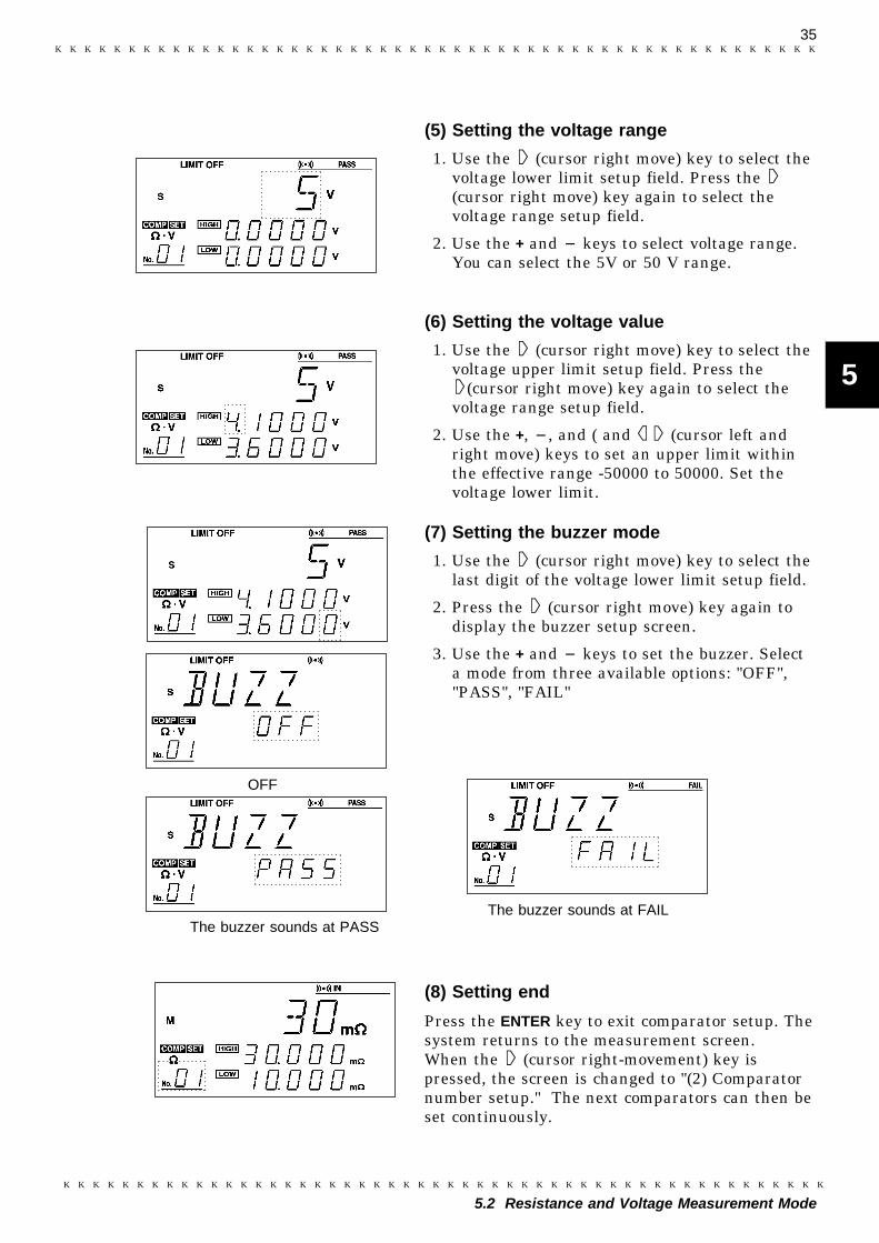
OFF
The buzzer sounds at PASSThe buzzer sounds at FAIL
(5) Setting the voltage range
1. Use the (cursor right move) key to select thevoltage lower limit setup field. Press the(cursor right move) key again to select thevoltage range setup field.
2. Use the + and keys to select voltage range.You can select the 5V or 50 V range.
(6) Setting the voltage value
1. Use the (cursor right move) key to select thevoltage upper limit setup field. Press the
(cursor right move) key again to select thevoltage range setup field.
2. Use the +, , and ( and (cursor left andright move) keys to set an upper limit withinthe effective range -50000 to 50000. Set thevoltage lower limit.
(7) Setting the buzzer mode
1. Use the (cursor right move) key to select thelast digit of the voltage lower limit setup field.
2. Press the (cursor right move) key again todisplay the buzzer setup screen.
3. Use the + and keys to set the buzzer. Selecta mode from three available options: "OFF","PASS", "FAIL"
(8) Setting end
Press the ENTER key to exit comparator setup. Thesystem returns to the measurement screen.When the (cursor right-movement) key ispressed, the screen is changed to "(2) Comparatornumber setup." The next comparators can then beset continuously.

36
5.3 Selecting the AUTO/MANU Comparator Mode
NOTE
5.3 Selecting the AUTO/MANU Comparator Mode
Selecting the AUTO/MANU Comparator Mode
This instrument supports two mode options: an auto comparator mode inwhich the comparator is used for every sampling to display and outputresults, and a manual comparator mode in which comparator operationresults are output only when the result indication is requested. Thecurrent mode (MANU or AUto) flashes in the comparator auto/manualsetup screen.
1. Pressing the COMP key toggle the comparatoron. "COMP" appears lit on the display.
2. Press the SHIFT key. "SHIFT" appears lit onthe display.
3. Press the COMP No. (AUTO/MANU) key todisplay the comparator auto/manual setupscreen.
4. Use the + and keys to select MANU or AUto.The selected mode will flash.
5. Press ENTER to exit the comparatorauto/manual setup screen. The system returnsto the measurement screen.
・ The manual comparator setting is enabled only for the external outputterminal. The manual comparator cannot be used for the display or thebuzzer.・ For more information on the manual comparator, see Chapter 6 "External
Control Terminal and External Output Terminal."・ When this setup screen is active, only the +, , SHIFT, and ENTER keys
are enabled.
37
5.4 Changing the Comparator Number
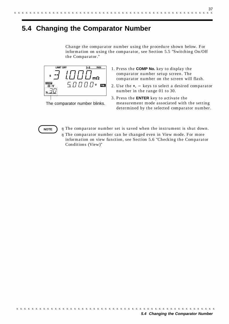
The comparator number blinks.
NOTE
5.4 Changing the Comparator Number
Change the comparator number using the procedure shown below. Forinformation on using the comparator, see Section 5.5 "Switching On/Offthe Comparator."
1. Press the COMP No. key to display thecomparator number setup screen. Thecomparator number on the screen will flash.
2. Use the +, keys to select a desired comparatornumber in the range 01 to 30.
3. Press the ENTER key to activate themeasurement mode associated with the settingdetermined by the selected comparator number.
・ The comparator number set is saved when the instrument is shut down.・ The comparator number can be changed even in View mode. For more
information on view function, see Section 5.6 "Checking the ComparatorConditions (View)"

38
5.5 Switching On/Off the Comparator
Comparator: ON
Comparator: OFF
NOTE
Comparator output (Resistance measurement mode)
Resistance Hi(Amber) IN(Green) Lo(Amber)
Comparator output (Resistance/voltage measurement mode)
ResistanceVoltage Hi IN Lo
Hi FAIL(Red) FAIL(Red) FAIL(Red)
IN FAIL(Red) PASS(Green) FAIL(Red)
Lo FAIL(Red) FAIL(Red) FAIL(Red)
5.5 Switching On/Off the Comparator
Pressing the COMP key toggles the comparator onand off. When the comparator is on, "COMP"appears lit on the display and the comparatorfunction is executed. When the comparator is off,"COMP" is not lit, and the comparator functiondoes not execute.
・ If the manual comparator is selected, thecomparator function is executed while theinstrument is controlled via the EXT.I/Oterminal. For more information, see Section 5.3"Selecting the AUTO/MANU Comparator Mode."・ Changing the resistance or voltage range
automatically turns off the comparator. Press theCOMP key to use the comparator. This activatesthe range set in the comparator.・ In the absence of a measured value, "- - - - -"
appears, and the comparator function is disabled.
Comparator comparison table
Judgment results are output to the display according to the table below.
The boundary condition is as follows:Resistance Lo < Lower resistance limit ≦ Resistance INResistance IN ≦ Upper resistance limit < Resistance HiVoltage Lo < Lower voltage limit ≦ Voltage INVoltage IN ≦ Upper voltage limit < Voltage Hi
When the upper limit is equal to the lower limit, the boundary conditionis changed as follows:Resistance Lo ≦ Lower resistance limit = Resistance INResistance IN = Upper resistance limit < Resistance HiUpper resistance limit < Resistance HiVoltage Lo ≦ Lower voltage limit = Voltage INVoltage IN = Upper voltage limit < Voltage Hi
39
5.6 Checking the Comparator Conditions (View)
5.6.1 View in Comparator of Resistance Measurement ModeSetting
NOTE
5.6 Checking the Comparator Conditions (View)
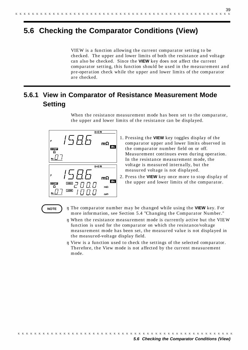
VIEW is a function allowing the current comparator setting to bechecked. The upper and lower limits of both the resistance and voltagecan also be checked. Since the VIEW key does not affect the currentcomparator setting, this function should be used in the measurement andpre-operation check while the upper and lower limits of the comparatorare checked.
When the resistance measurement mode has been set to the comparator,the upper and lower limits of the resistance can be displayed.
1. Pressing the VIEW key toggles display of thecomparator upper and lower limits observed inthe comparator number field on or off.Measurement continues even during operation.In the resistance measurement mode, thevoltage is measured internally, but themeasured voltage is not displayed.
2. Press the VIEW key once more to stop display ofthe upper and lower limits of the comparator.
・ The comparator number may be changed while using the VIEW key. Formore information, see Section 5.4 "Changing the Comparator Number."・ When the resistance measurement mode is currently active but the VIEW
function is used for the comparator on which the resistance/voltagemeasurement mode has been set, the measured value is not displayed inthe measured-voltage display field.・ View is a function used to check the settings of the selected comparator.
Therefore, the View mode is not affected by the current measurementmode.

40
5.6 Checking the Comparator Conditions (View)
5.6.2 View in Comparator of Resistance and VoltageMeasurement Mode Setting
NOTE
When the resistance/voltage measurement mode has been set to thecomparator, the upper and lower limits of both the resistance and voltagecan be displayed.
1. Pressing the VIEW key stops displaying themeasured voltage, displaying instead the upperand lower limits of the resistance comparatorobserved in the comparator number field.
2. Pressing the VIEW key again stops display of themeasured resistance, displaying instead themeasured voltage. In parallel with this action,the screen displays the upper and lower limits ofthe voltage comparator observed in thecomparator number field.
3. When the VIEW key is pressed again, the upperand lower limits of the comparator disappearand the system returns to the measurementscreen.
・ The comparator number may be changed while using the VIEW key. Formore information, see Section 5.4 "Changing the Comparator Number."・When the resistance measurement mode is currently active but the
VIEW function is used for the comparator on which the resistance/voltagemeasurement mode has been set, the measured value is not displayed inthe measured-voltage display field.・ In the resistance and voltage measurement mode, the resistance (and/or
voltage) not displayed on the screen is also measured.
41
1
2
3
4
5
6
7
8
9
10
11
12
13
14
A
Chapter 6External Control Terminal and
External Output Terminal
The 3560 is provided with external control and output terminals andsupports the RS-232C interface and the optional GP-IB interfaceconnector and printer interface. The external control terminal permitsuse of the measurement trigger, comparator trigger, printer trigger, andzero-adjust, comparator selection functions.Results of comparator operation and signals indicating abnormalmeasurements and end of measurement are output from the externaloutput terminal. Use these functions to establish a measurementsequence for the line.
42
6.1 Terminals and Signals
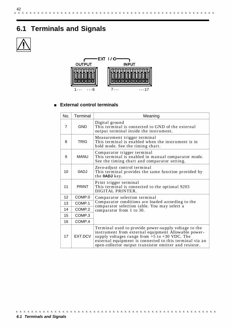
1・・・ ・・・17・・・6 7・・・
No. Terminal Meaning
7 GNDDigital groundThis terminal is connected to GND of the externaloutput terminal inside the instrument.
8 TRIGMeasurement trigger terminalThis terminal is enabled when the instrument is inhold mode. See the timing chart.
9 MANUComparator trigger terminalThis terminal is enabled in manual comparator mode.See the timing chart and comparator setting.
10 0ADJZero-adjust control terminalThis terminal provides the same function provided bythe 0ADJ key.
11 PRINTPrint trigger terminalThis terminal is connected to the optional 9203DIGITAL PRINTER.
12 COMP.0 Comparator selection terminalComparator conditions are loaded according to thecomparator selection table. You may select acomparator from 1 to 30.
13 COMP.1
14 COMP.2
15 COMP.3
16 COMP.4
17 EXT.DCV
Terminal used to provide power-supply voltage to theinstrument from external equipment Allowable power-supply voltages range from +5 to +30 VDC. Theexternal equipment is connected to this terminal via anopen-collector output transistor emitter and resistor.
6.1 Terminals and Signals
External control terminals
43
6.1 Terminals and Signals
1
2
3
4
5
6
7
8
9
10
11
12
13
14
A
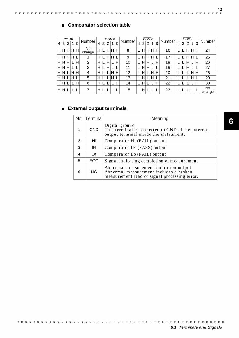
Number Number Number Number4 3 2 1 0 4 3 2 1 0 4 3 2 1 0 4 3 2 1 0
H H H H H Nochange H L H H H 8 L H H H H 16 L L H H H 24
H H H H L 1 H L H H L 9 L H H H L 17 L L H H L 25H H H L H 2 H L H L H 10 L H H L H 18 L L H L H 26H H H L L 3 H L H L L 11 L H H L L 19 L L H L L 27H H L H H 4 H L L H H 12 L H L H H 20 L L L H H 28H H L H L 5 H L L H L 13 L H L H L 21 L L L H L 29H H L L H 6 H L L L H 14 L H L L H 22 L L L L H 30
H H L L L 7 H L L L L 15 L H L L L 23 L L L L L Nochange
COMP COMP COMPCOMP
No. Terminal Meaning
1 GNDDigital groundThis terminal is connected to GND of the externaloutput terminal inside the instrument.
2 Hi Comparator Hi (FAIL) output3 IN Comparator IN (PASS) output4 Lo Comparator Lo (FAIL) output5 EOC Signal indicating completion of measurement
6 NGAbnormal measurement indication outputAbnormal measurement includes a brokenmeasurement lead or signal processing error.
Comparator selection table
External output terminals
44
6.2 Connection Method
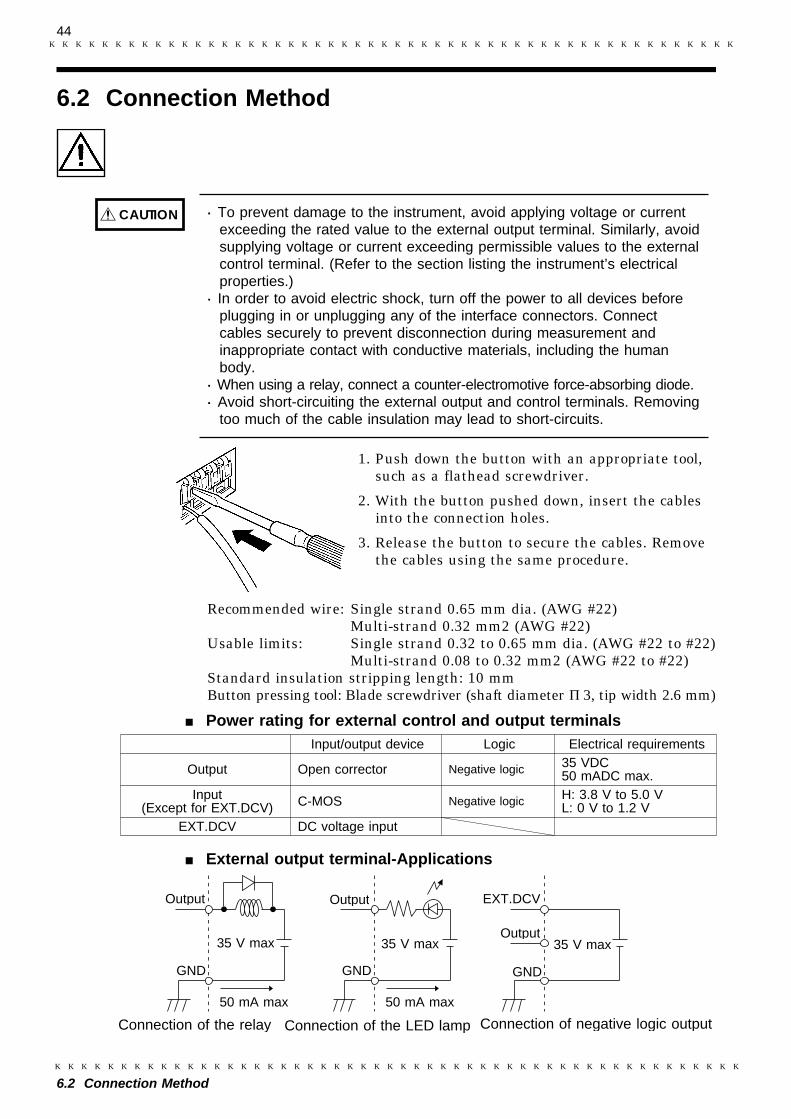
CAUTION ・ To prevent damage to the instrument, avoid applying voltage or currentexceeding the rated value to the external output terminal. Similarly, avoidsupplying voltage or current exceeding permissible values to the externalcontrol terminal. (Refer to the section listing the instrument’s electricalproperties.)・ In order to avoid electric shock, turn off the power to all devices before
plugging in or unplugging any of the interface connectors. Connectcables securely to prevent disconnection during measurement andinappropriate contact with conductive materials, including the humanbody.・ When using a relay, connect a counter-electromotive force-absorbing diode.・ Avoid short-circuiting the external output and control terminals. Removing
too much of the cable insulation may lead to short-circuits.
Input/output device Logic Electrical requirements
Output Open corrector Negative logic 35 VDC50 mADC max.
Input(Except for EXT.DCV) C-MOS Negative logic H: 3.8 V to 5.0 V
L: 0 V to 1.2 VEXT.DCV DC voltage input
Output
35 V max
GND
50 mA max
Output
35 V max
GND
50 mA max
EXT.DCV
35 V max
GND
Output
Connection of the relay Connection of the LED lamp Connection of negative logic output
6.2 Connection Method
1. Push down the button with an appropriate tool,such as a flathead screwdriver.
2. With the button pushed down, insert the cablesinto the connection holes.
3. Release the button to secure the cables. Removethe cables using the same procedure.
Recommended wire: Single strand 0.65 mm dia. (AWG #22) Multi-strand 0.32 mm2 (AWG #22)Usable limits: Single strand 0.32 to 0.65 mm dia. (AWG #22 to #22) Multi-strand 0.08 to 0.32 mm2 (AWG #22 to #22)Standard insulation stripping length: 10 mmButton pressing tool: Blade screwdriver (shaft diameterφ3, tip width 2.6 mm)
Power rating for external control and output terminals
External output terminal-Applications
45
6.3 Measurement by External Control Terminal and External Output Terminal
1
2
3
4
5
6
7
8
9
10
11
12
13
14
A
6.3.1 External Control Terminal (Input Signal)
6.3 Measurement by External Control Terminal andExternal Output Terminal
In the text below, "H" and "L" refer to the following two respective states:H: No input or input of GND +3.8 to GND +5 V.L: Input of GND +0 to GND +1.2 V. (Short-circuited to GND)
Measurement trigger (TRIG)
The displayed data is updated when this input signal is changed from "H"to "L" (i.e. the fall edge is created) in measurement-hold mode. For moreinformation on hold mode, see Section 4.3.3 "Hold."
Comparator output request (MANU)
When the external output terminal mode is set to MANU in thecomparator setting, the comparator result is output while this inputsignal remains "L." For more information on comparator settings, seeSection 5.1 "Resistance Measurement Mode" and Section 5.2 "Resistanceand Voltage Measurement Mode."
Zero-adjust request (0ADJ)
Zero-adjust is implemented when this input signal is changed from "H" to"L" (i.e. the fall edge is created) during measurement. For moreinformation on zero-adjust, see Section 4.4 "Zero Adjust."
Print request (PRINT)
This signal is used to output measurement data from the optional digitalprinter (9203) or general-purpose Centronics printer. For moreinformation on printers, see Chapter 9 "Printer Interface."
Comparator number selection (COMP0 to COMP4)
Select the comparator number from Section 6.1 "Terminals and Signals."For more information on comparators, see Chapter 5 "ComparatorFunction."
Hold on/off (EXT HOLD)
Use the 9466 REMOTE CONTROL SWITCH (option) to turn hold modeon or off.
46
6.3 Measurement by External Control Terminal and External Output Terminal
NOTE
6.3.2 External Output Terminal (Output Signal)
NOTE
The input signal is disabled under the following conditions. Any functiondependent on the signal is also disabled.
・ Selection of a comparator No. (COMP0 - COMP4) during communicationsvia RS-232 or GP-IB・ The measurement trigger (TRIG) is issued if the instrument is not in hold
mode.・ The comparator output request (MANU) is issued if the comparator is not
used when the external output terminal mode is set to AUTO in thecomparator setting.・ Print request (PRINT) is issued when no printer interface (9589) is
connected.・ The comparator number (COMP0 to COMP4) is selected while the
comparator setup screen is displayed.・ The measurement trigger (TRIG) is issued while the zero-adjust executes.・ The comparator is automatically turned on and auto-range changed to
manual range if the comparator number is selected by the comparatornumber selection signal (COMP0 to COMP4) while auto-range is used.・ When the comparator number (COMP0 to COMP4) is used, the remote
mode is active.
In the following text, "0" and "1" indicate the following two respectivestates:0: The output transistor is turned off, and no current flows through it.1: The output transistor is turned on, and current flows through it.
Comparator result (Hi (FAIL), IN (PASS), Lo (FAIL))When the result is "1," the comparator result associated with the signal isvalid.
End of measurement (EOC)A change from "0" to "1" in this signal indicates that currentmeasurement is complete, and that the comparator result output isdetermined.
Abnormal measurements (NG)A value of "1" indicates an abnormal measurement. This signal is set to"1" even when abnormal measurements are detected in hold mode.Abnormal measurement results indicate a broken lead, incorrect contact,or defective internal analog circuits. For more information on abnormalmeasurements, see Section 4.5 "Starting Measurement."
・ If the comparator is not used, or if the mode of the comparator externalcontrol terminal is MANU but the comparator output request (MANU) isnot issued, "0" is output for all comparator results (Hi (FAIL), IN (PASS),and Lo (FAIL)). In the NG state, "0" is output for all comparator results(Hi (FAIL), IN (PASS), and Lo (FAIL)).・ If no measurement is carried out after the instrument is turned on, all
output signals are set to "0." When the comparator result is FAIL inresistance and voltage mode, Hi (FAIL) and IN (PASS) aresimultaneously set to "1."
47
6.3 Measurement by External Control Terminal and External Output Terminal
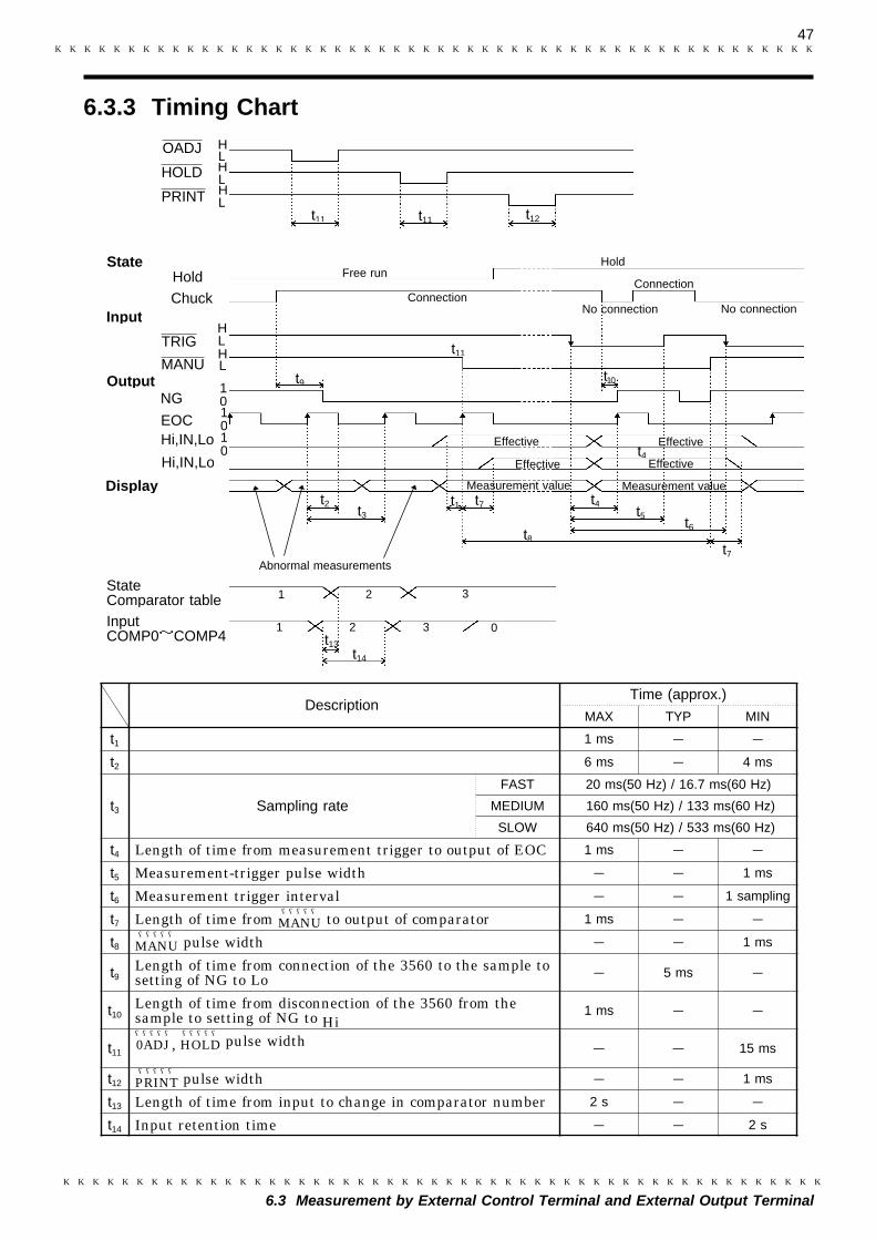
6.3.3 Timing Chart
H
H
L
H
HOLDL
OADJ
Hold
Chuck
TRIG
MANUOutput
Input
NG
EOCHi,IN,Lo
Hi,IN,Lo
Display
10
State Comparator tableInput COMP0~COMP4
t11 t12
t11
t14
t13
Free runHold
No connectionConnection
No connection
Connection
Effective
Measurement value
t4
Abnormal measurements
Measurement value
Effective
Effective
t9 t10
t2t3
t1 t7t5
t7
t4
t8t6
1
21
32
3 0
State
HL
t11
Effective
HL
1010
L
DescriptionTime (approx.)
MAX TYP MIN
t1 1 ms - -
t2 6 ms - 4 ms
t3 Sampling rate
FAST 20 ms(50 Hz) / 16.7 ms(60 Hz)
MEDIUM 160 ms(50 Hz) / 133 ms(60 Hz)
SLOW 640 ms(50 Hz) / 533 ms(60 Hz)
t4 Length of time from measurement trigger to output of EOC 1 ms - -
t5 Measurement-trigger pulse width - - 1 ms
t6 Measurement trigger interval - - 1 sampling
t7 Length of time from MANU―――――
to output of comparator 1 ms - -
t8 MANU―――――
pulse width - - 1 ms
t9Length of time from connection of the 3560 to the sample tosetting of NG to Lo - 5 ms -
t10Length of time from disconnection of the 3560 from thesample to setting of NG to Hi
1 ms - -
t110ADJ―――――
, HOLD―――――
pulse width - - 15 ms
t12 PRINT―――――
pulse width - - 1 ms
t13 Length of time from input to change in comparator number 2 s - -
t14 Input retention time - - 2 s

48
6.3 Measurement by External Control Terminal and External Output Terminal
【Input】
COMP0 to 4
【State】Comparator
number 2
1 2
31
3H
L
【State】
Chuck
【Output】
NG1
0【Input】
TRIG
【Output】
H
L
【Output】
EOC
Hi,IN,Lo
1
0
1
0Effective
FAST MEDIUM SLOW
Frequency: 50 Hz Approx.95 ms Approx.795 ms Approx.1.92 s
Frequency: 60 Hz Approx.80 ms Approx.660 ms Approx.1.60 s
(1) Selecting Comparator Number
When reselecting comparator number by external control terminalsignal, use COMP 0 to 4. After reselecting comparator number,keep the same signal status.Comparator number is reselected. Starts measurement after 3560setting is stabilized.
(2) Measurement using trigger function
Connect object to be measured to measurement lead.Measurement error signal(NG) is disengaged.TRIG―――――――――
signal is output after time to stabilize is reached.Invalid when in free run status.Waiting time(response time)is as follows depending on sampling.This value applies in the case of pure resistance.Waiting time varies depending on type of object to be measured.Adjust it after measurement and when value fluctuates, enterlarger value.
Removes object to be measuredOutputs measurement error signal (NG). Repeats processes from .
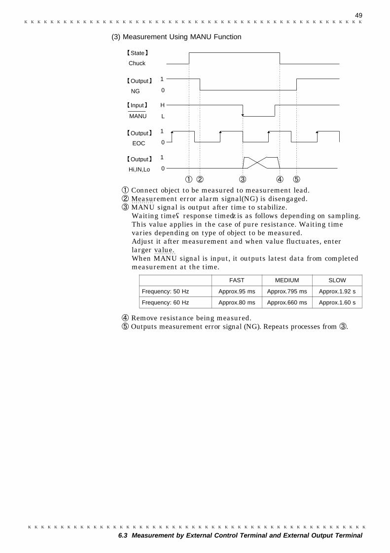
49
6.3 Measurement by External Control Terminal and External Output Terminal
1
0
H
L
1
0
1
0
【State】
Chuck
【Output】
NG
【Input】
MANU
【Output】
【Output】
EOC
Hi,IN,Lo
FAST MEDIUM SLOW
Frequency: 50 Hz Approx.95 ms Approx.795 ms Approx.1.92 s
Frequency: 60 Hz Approx.80 ms Approx.660 ms Approx.1.60 s
(3) Measurement Using MANU Function
Connect object to be measured to measurement lead.Measurement error alarm signal(NG) is disengaged.MANU―――――――――――
signal is output after time to stabilize.Waiting time(response time)is as follows depending on sampling.This value applies in the case of pure resistance. Waiting timevaries depending on type of object to be measured.Adjust it after measurement and when value fluctuates, enterlarger value.When MANU
―――――――――――
signal is input, it outputs latest data from completedmeasurement at the time.
Remove resistance being measured.Outputs measurement error signal (NG). Repeats processes from .
50
6.3 Measurement by External Control Terminal and External Output Terminal
NOTE ・ When loading measurement result using TRIG signal, be sure to monitorEOC signal status and load measurement result after EOC signal isoutput. When loading measurement result without monitoring EOCsignal, load data after TRIG signal is input and some time has passed.・ Comparator result(Hi,IN,Lo,PASS,FAIL)is not output in the following
situations.・ When comparator is set to MANU and MANU signal is not input.・ When NG (measurement error) occurs. (See 4.5 Starting Measurement)・ When connecting 9203 printer to 3560 and print measurement value
synchronized with measurement, use 9425 CONNECTION CABLE onlyfor connection.・ When printing measurement value, input 3560 PRINT signal at timing
after measurement is complete.・ When measurement value is printed using 9203 PRINT signal or Interval
print function, use caution because measurement and printing may notsynchronize and printing a previous measurement value may occur.・ Timing chart shows standard examples. It may very depending on users’
application. When building line, etc, adjust waiting time and signal pulsewidth if operation error occurs or measurement value fluctuates.・ When building fastest line possible, first set parameter such as waiting
time long and shorten each parameter as normal operation is confirmed.・ When line settings are proper and operation errors still occur, it may be
the result of noise in the testing environment. Try the following solutions.・ Install filter in the power supply 3560 and control equipment.・ Use other power source for 3560 and control equipment. Isolate with
transformer, etc.・ Separate measurement leads, control signal and power supply line.・ Shorten control signal and measurement lead’s wire length.・ Place control signal and measurement lead away from noise source
such as control equipment.・ Do not connect signal wire leads, etc to the unused terminal board.・ When 3560 control equipment and other equipment are connected with
control wires, separate control signal of other equipment and 3560control signal.

51
6.3 Measurement by External Control Terminal and External Output Terminal
6.3.4 Internal Circuit Configuration (Input/Output)
Protection diode
4.7 kΩ
0.1μF
Protection diode
22 Ω
H-CMOS
EXT.DCV
20 kΩ
Output
GND
NOTE
These respective charts illustrate the circuit configuration of the externalcontrol terminal (input) and the external output terminal (output). Theexternal control terminal operates at the CMOS level.
Circuit configuration of the external control terminal
Circuit configuration of the external output terminal
Signal leads are functionally separate from measurement leads in orderto prevent interaction between these lead groups. To preserve theinsulation, be sure to ground the equipment if it’s connected to the 3560.

52
6.3 Measurement by External Control Terminal and External Output Terminal
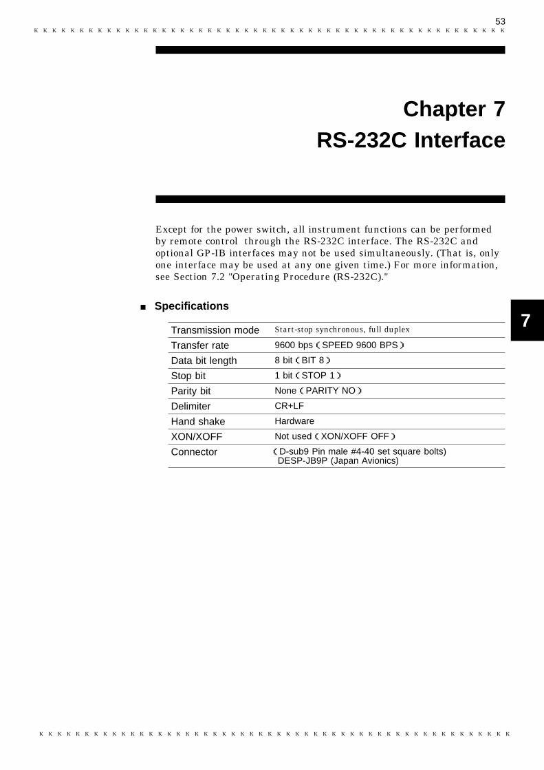
53
1
2
3
4
5
6
7
8
9
10
11
12
13
14
A
Transmission mode Start-stop synchronous, full duplex
Transfer rate 9600 bps(SPEED 9600 BPS)
Data bit length 8 bit(BIT 8)
Stop bit 1 bit(STOP 1)
Parity bit None(PARITY NO)
Delimiter CR+LF
Hand shake Hardware
XON/XOFF Not used(XON/XOFF OFF)
Connector (D-sub9 Pin male #4-40 set square bolts)DESP-JB9P (Japan Avionics)
Chapter 7RS-232C Interface
Except for the power switch, all instrument functions can be performedby remote control through the RS-232C interface. The RS-232C andoptional GP-IB interfaces may not be used simultaneously. (That is, onlyone interface may be used at any one given time.) For more information,see Section 7.2 "Operating Procedure (RS-232C)."
Specifications

54
7.1 Connection to Computer (RS-232C)
WARNING To avoid electrocution, turn off the power to all devices beforeplugging or unplugging any of the interface connectors.
To avoid damage to the instrument, do not short the output terminaland do not input voltage to the output terminal.
Rear panel of the instrument
1 2 3 4 5
6 7 8 9
Connector(D-sub)
Pin number
SignalName
RS-232C CCITT JIS
1 Not used
2 BB(RxD) 104 RD Data of reception
3 BA(TxD) 103 SD Data of transmission
4 CD(DTR) 108/2 ER Data terminal ready
5 AB(GND) 102 SG Signal ground
6 CC(DSR) 107 DR Not used
7 CA(RTS) 105 RS Request for transmission
8 CB(CTS) 106 CS Transmission ready
9 Not used
D-sub9pin female
74
2
6
345
8SHELL
3265
87SHELL
Cable
D-sub9pin female
5
SHELL
5
1234
67
83220
4
7
D-sub9pin male
D-sub25pin male
9
SHELL
228
1
6
Conversion connector
D-sub9pin female
74
2
6
345
8SHELL
3265
87SHELL
Cable
D-sub9pin female
7.1 Connection to Computer (RS-232C)
To connect the 3560 and a PC, attach one end of the RS-232C cable to theinstrument’s RS-232C connector and the other end to the PC serial port.
Usable cable conditions
Connection: Reverse-type connectionThe figure below gives a wiring diagram.This particular example shows a connection to a PC/ATcompatible.
Connecting to PC98 compatibles
Use a 9-pin cable and 9/25conversion pin connector toconnect the 3560 to a PC98-series machine.

55
7.2 Operating Procedure (RS-232C)
1
2
3
4
5
6
7
8
9
10
11
12
13
14
A
7.2.1 Setting the RS-232C
NOTE
7.2.2 Communication Methods by the RS-232C
Program messages
Response messages
Command messages
Query messagesMessages
7.2 Operating Procedure (RS-232C)
Establishes communications. See the description below for hard flow.
1. Press the SHIFT key. "SHIFT" appears lit on thedisplay..
2. Press the DOWN/INTERFACE key.
3. Use the + and keys to select RS-232C( ).
4. Press the ENTER key.
5. Use the + and keys to turn hard flow on oroff.
6. Press the ENTER key to return to themeasurement screen.
Hard flow
Hard flow sets flow control (RTS/CTS) when data is transferred throughthe RS-232C interface. With hard flow enabled, data flow is controlled bythe data transmission request signal (RTS) and transmission permitsignal (CTS) between the 3560 and computer.RTS: A PC outputs this signal to indicate readiness to receive data from a
peripheral device.CTS: A peripheral device outputs this signal to indicate readiness to
receive data from the PC.For information on setting flow control, refer to the operating manual foryour PC. Make sure settings for the 3560 and the PC match.
If the 9588 GP-IB INTERFACE is not mounted,GP-IB cannot be selected.
In order to control the 3560 by the RS-232C, there are several kinds ofmessages. Of these, program messages are those received by the 3560from the computer, while response messages are those sent from the 3560to the computer.
56
7.2 Operating Procedure (RS-232C)
7.2.3 Program Messages
7.2.4 Message Format
NOTE
Program messages are command messages or query messages.
(1) Command messages
Command messages are orders for controls of the 3560, such as formaking measurement condition settings or for reset or the like.
Example :LIM ON
(2) Query messages
Query messages are order for responses relating to results ofmeasurement, or the state of 3560 settings. (A question mark"?"issuffixed at the end of the command.)
Example :CSET:BEEP?
The commands for the 3560 are as far as possible mnemonic.Furthermore, all commands have a long form, and an abbreviated shortform.
(1) Program message
The program message is made up from header and data portions.Example :AUT ONAUT: HeaderON: Data(ASCII codes or numerical characters. Messages containing no data also exist inthe form of query messages.)
A command header can be abbreviated. The whole command form isreferred to as the "long form" and the abbreviated from as the "shortform."In this manual, the short form is written in upper case letters, and thenthis is continued in lower case letters so as to constitute the long form.Either of these forms will be accepted during operation, but intermediateforms will not be accepted. Further, during operation both lower caseletters will be accepted without distinction.
(2) Response messages
It represents the response message for query messages from the 3560.Response messages generated by the 3560 are in long form and in uppercase letters.
Example :CSET:BEEPER IN
・ If an error occurs when a query is received, no response message to thequery is sent.・ When occurring in the message reference, the symbol " "(space) indicates
a space.

57
7.2 Operating Procedure (RS-232C)
1
2
3
4
5
6
7
8
9
10
11
12
13
14
A
7.2.5 Headers
(1) Program message headers
The program message always requires a header.These are three types of header: simple headers, compound headers, andparticular headers.
Simple header
A header consisting of a single word beginning with a letter.
Example :AUTorange
Compound header
A header consisting of a sequence of words separated by colons.Example :LOCK:KEY
Particular header
A header beginning with an asterisk (*) to indicate that it is a particularcommand.Example *CLS
(2) Response message
Headers in response message can be enabled or disabled by using the":HEADer" command.Example :CSET:BEEP? (Queries the buzzer setting)Response: [If headers are ON] :CSET:BEEPER INResponse: [If headers are OFF] IN (Data only)
58
7.2 Operating Procedure (RS-232C)
7.2.6 Data Formats
7.2.7 Delimiters
The 3560 use character string data and decimal numeric data, and thetype used varies according to the command in question.
(1) Character data
Character string data must always being with an alphabetic character,and the characters following can be either alphabetic characters ornumerals. Although in character data either upper case letters or lowercase letters are accepted, response messages output by the 3560 arealways in upper case letters.
Example :LIMIT ON
(2) Decimal data
The numeric data values are all represented in decimal, in three formatsidentified as NR1, NR2 and NR3, and each of these can appear as eithera signed number or an unsigned number. Unsigned numbers are taken aspositive.Further, if the accuracy of a numerical value exceeds the limit which the3560 can deal, it is rounded off. (5 and above is rounded up; 4 and belowis rounded down)
NR1 format - integer data.
Example +3000, -50000, 210NR2 format - fixed point numbers.
Example +2.56, -30.45, 300.28NR3 format - floating point numbers.
Example +3E-2, -1.2E3The term "NRf format" includes all these three formats.When the 3560 is receiving it accepts NRf format, but when it is sendingresponse messages it utilizes whichever one of the formats NR1 to NR3 isindicated in the specified command.Example :VRAN 5 :VRAN 5.01 :VRAN 0.05E2
The term "delimiter" is used to refer to the following two possibilities forseparating data sequences.The response message delimiter has the following two format:CR + LF, CR, LFThe output is CR + LF.
59
7.2 Operating Procedure (RS-232C)
7.2.8 Separators
7.2.9 Abbreviation of Compound Commands
(1) Message unit separator
A semicolon (;) is used as a message unit separator when it is desired toset out several messages on a single line.When message are combined in this way, if a syntax error occurs, allsubsequent messages up to the next delimiter will be ignored.Example :RRAN 3E-2;:VRAN 50;:MEAS:BATT?
(2) Header separator
In a message which has a header and data, a apace (represented by ""(space) in the examples) is used as the header separator to separate theheader from the data.Example :COMPARATOR 1
(3) Data separator
If a message has several data items, commas (,) are required as dataseparators for separating these data items from one another.Example :CSET:RPAR data1,data2
When several compound headers have a common head portion (forexample, :CSET: ), then, when and only when writing them directlyfollowing on from one another, this common portion (:CSET: in thisexample) can be omitted.This common portion is called "the current path", by analogy with thegeneral concept of the current directly in the directly structure of UNIXor MSDOS, and until it is cleared the analysis of following commands isperformed by deeming them to be preceded by the current path is shownin the following example:
Normal expression:CSET:NUMBer;:CSET:RPARameter
Abbreviated expression:CSET:NUMBer;RPARameter
The current path is cleared when the power is turned on, when a colon (:)appears at the start of a command, and when delimiter is detected.
Messages with particular headers can be executed without relation to thecurrent path. Further, they have no effect upon the current path.While simple and complex command headers don’t require a colon ": "prefix, we recommend using the colon to avoid confusion with abbreviatedexpressions and to prevent 3560 malfunction.
With the 3560, there are 3 possible current paths:":CSET", ":LOCK", ":MEAS"
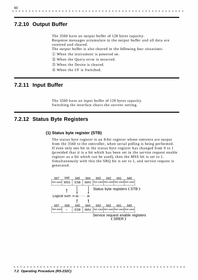
60
7.2 Operating Procedure (RS-232C)
7.2.10 Output Buffer
7.2.11 Input Buffer
7.2.12 Status Byte Registers
ESBNot used
bit6Not used
Not usedNot used
MSS MAVbit7 bit5 bit4 bit3 bit2 bit1 bit0
Logical sum &&
bit3 bit1 bit0ESB MAVbit5 bit4
Not used ×bit7 bit6
Status byte registers(STB)
Service request enable registers(SRER)
Not used Not used
Not used Not used Not used
bit2
The 3560 have an output buffer of 128 bytes capacity.Response messages accumulate in the output buffer and all data arereceived and cleared.The output buffer is also cleared in the following four situations:
When the instrument is powered on.When the Query error is occurred.When the Device is cleared.When the I/F is Switched.
The 3560 have an input buffer of 128 bytes capacity.Switching the interface clears the current setting.
(1) Status byte register (STB)
The status byte register is an 8-bit register whose contents are outputfrom the 3560 to the controller, when serial polling is being performed.If even only one bit in the status byte register has changed from 0 to 1(provided that it is a bit which has been set in the service request enableregister as a bit which can be used), then the MSS bit is set to 1.Simultaneously with this the SRQ bit is set to 1, and service request isgenerated.
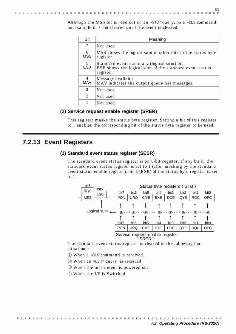
61
7.2 Operating Procedure (RS-232C)
Bit Meaning7 Not used6
MSSMSS shows the logical sum of other bits in the status byteregister.
5ESB
Standard event summary (logical sum) bitESB shows the logical sum of the standard event statusregister.
4MAV
Message availableMAV indicates the output queue has messages.
3 Not used2 Not used1 Not used
7.2.13 Event Registers
bit2
DDEURQ CME EXEbit6 bit5 bit4 bit3
Logical sum &&
bit3 bit1CME EXEbit5 bit4
PON URQbit7 bit6
Status byte registers(STB)
Service request enable register(SRER)
DDE QYE RQC OPC
QYE RQC OPCPON
& & & &&&
ESBRQS
MSS
bit6bit5
bit7 bit2 bit1 bit0
bit0
Although the MSS bit is read out on an *STB? query, on a *CLS commandfor example it is not cleared until the event is cleared.
(2) Service request enable register (SRER)
This register masks the status byte register. Setting a bit of this registerto 1 enables the corresponding bit of the status byte register to be used.
(1) Standard event status register (SESR)
The standard event status register is an 8-bit register. If any bit in thestandard event status register is set to 1 (after masking by the standardevent status enable register), bit 5 (ESB) of the status byte register is setto 1.
The standard event status register is cleared in the following foursituations:
When a *CLS command is received.When an *ESR? query is received.When the instrument is powered on.When the I/F is Switched.
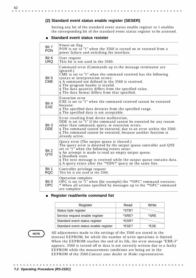
62
7.2 Operating Procedure (RS-232C)
Bit 7PON
Power-on flagPON is set to "1" when the 3560 is turned on or restored from apower failure and switching the interface.
Bit 6URQ
User requestThis bit is not used in the 3560.
Bit 5CME
Command error (Commands up to the message terminator areignored.)CME is set to "1" when the command received has the followingsyntax or interpretation errors:・ A command not defined in the 3560 is received.・ The program header is invalid.・ The data quantity differs from the specified value.・ The data format differs from that specified.
Bit 4EXE
Execution errorEXE is set to "1" when the command received cannot be executedbecause:・ The specified data deviates from the specified range.・ The specified data is not acceptable.
Bit 3DDE
Error resulting from device malfunction.DDE is set to "1" if the command cannot be executed for any reasonother than command, query, or execution errors.・ The command cannot be executed, due to an error within the 3560.・ The command cannot be executed, because another function isalready active.
Bit 2QYE
Query error (The output queue is cleared.)The query error is detected by the output queue controller and QYEset to "1" when the following events occur:・ An attempt is made to read an empty output queue.・ Deadlock state・ The next message is received while the output queue contains data.・ A query exists after the "*IDN?" query on the same line.
Bit 1RQC
Controller privilege requestThis bit is not used in the 3560.
Bit 0OPC
Operation completeOPC is set to "1" when (for example) the "*OPC" command executes:* When all actions specified by messages up to the "*OPC" commandare complete
Register Read WriteStatus byte register *STB?
Service request enable register *SRE? *SRE
Standard event status register *ESR?
Standard event status enable register *ESE? *ESE
NOTE
(2) Standard event status enable register (SESER)
Setting any bit of the standard event status enable register to 1 enablesthe corresponding bit of the standard event status register to be accessed.
Standard event status resister
Register read/write command list
All adjustments made to the settings of the 3560 are stored in theinternal EEPROM, for which the number of write operations is limited.When the EEPROM reaches the end of its life, the error message "ERR-3"appears. 3560 is turned off or data is not correctly written due to a faultyEEPROM while the measurement conditions are being set in theEEPROM of the 3560.Contact your dealer or Hioki representative.
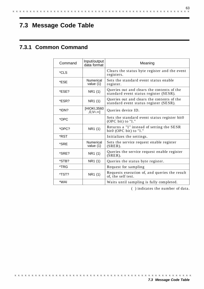
63
7.3 Message Code Table
7.3.1 Common Command
Command Input/outputdata format Meaning
*CLS Clears the status byte register and the eventregisters.
*ESE Numericalvalue (1)
Sets the standard event status enableregister.
*ESE? NR1 (1) Queries out and clears the contents of thestandard event status register (SESR).
*ESR? NR1 (1) Queries out and clears the contents of thestandard event status register (SESR).
*IDN? [HIOKI,3560,0,V*.**]
Queries device ID.
*OPC Sets the standard event status register bit0(OPC bit) to "1."
*OPC? NR1 (1) Returns a "1" instead of setting the SESRbit0 (OPC bit) to "1."
*RST Initializes the settings.
*SRE Numericalvalue (1)
Sets the service request enable register(SRER).
*SRE? NR1 (1) Queries the service request enable register(SRER).
*STB? NR1 (1) Queries the status byte register.*TRG Request for sampling
*TST? NR1 (1) Requests execution of, and queries the resultof, the self test.
*WAI Waits until sampling is fully completed.
7.3 Message Code Table
( ) indicates the number of data.

64
7.3 Message Code Table
7.3.2 Messages
Command Input/outputData format Meaning
:ADJust? Executes zero-adjust and queries theresult.
:AUTorange [ON/OFF] (1) Sets the auto range.
:AUTorange? [ON/OFF] (1) Queries for auto-range mode on/offstatus.
:COMParator Numerical value (1) Selects the comparator to be used.:COMParator? NR1 (1) Queries the comparator number.
:CSET:BEEPer [OFF/IN/HI] (1)[OFF/PASS/FAIL] (1)
Sets the buzzer for comparatordetermination.
:CSET:BEEPer? [OFF/IN/HI] (1)[OFF/PASS/FAIL] (1)
Queries the buzzer setting forcomparator.
:CSET:MODe [R/RV] (1) Sets for the measurement mode setfor the comparator.
:CSET:MODe? [R/RV] (1) Queries for the measurement modeset for the comparator.
:CSET:NUMBer Numerical value (1) Selects the number of comparator tobe set.
:CSET:NUMBer? NR1 (1) Queries the number of comparator tobe set.
:CSET:RPARameter Numerical value (2) Sets the upper and lower limits forcomparator resistance.
:CSET:RPARameter? NR3 (1) Queries the upper and lower limitsfor comparator resistance.
:CSET:RRANge Numerical value (1) Sets the resistance range used by thecomparator.
:CSET:RRANge? NR3 (1) Sets the resistance range used by thecomparator.
:CSET:VPARameter Numerical value (2) Sets for the comparator voltage upperand lower limits.
:CSET:VPARameter? NR3 (2) Queries for the comparator voltageupper and lower limits.
:CSET:VRANge Numerical value (1) Sets for the voltage range used bythe comparator.
:CSET:VRANge? NR3 (1) Queries for the voltage range used bythe comparator.
:CTMode [AUT/MAN] Sets the comparator mode.:CTMode? [AUT/MAN] Queries the comparator mode.
:FREQuency Numerical value (1) This command sets power supplyvoltage.
:FREQuency? NR1 (1) This command queries power supplyvoltage.
:HEADer [ON/OFF] (1) Enable and disable headers.:HEADer? [ON/OFF] (1) Queries the headers enablement.:HOLD [ON/OFF] (1) Sets the measurement hold.
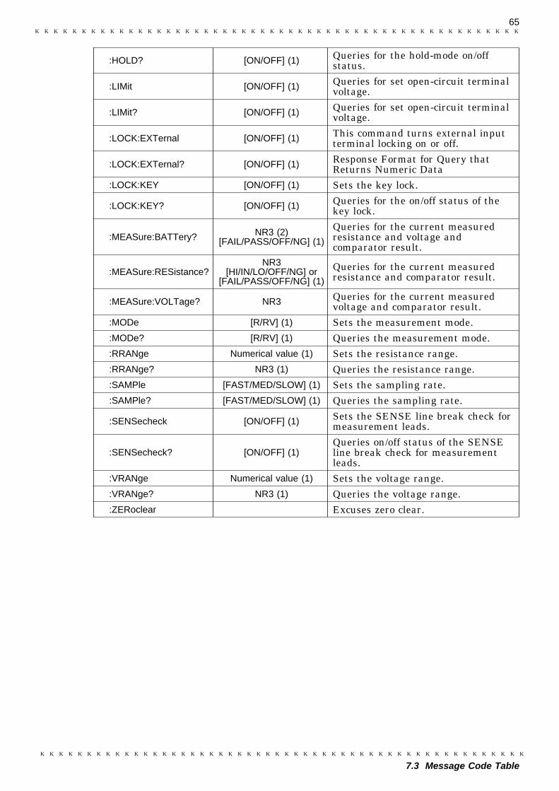
65
7.3 Message Code Table
:HOLD? [ON/OFF] (1) Queries for the hold-mode on/offstatus.
:LIMit [ON/OFF] (1) Queries for set open-circuit terminalvoltage.
:LIMit? [ON/OFF] (1) Queries for set open-circuit terminalvoltage.
:LOCK:EXTernal [ON/OFF] (1) This command turns external inputterminal locking on or off.
:LOCK:EXTernal? [ON/OFF] (1) Response Format for Query thatReturns Numeric Data
:LOCK:KEY [ON/OFF] (1) Sets the key lock.
:LOCK:KEY? [ON/OFF] (1) Queries for the on/off status of thekey lock.
:MEASure:BATTery? NR3 (2)[FAIL/PASS/OFF/NG] (1)
Queries for the current measuredresistance and voltage andcomparator result.
:MEASure:RESistance?NR3
[HI/IN/LO/OFF/NG] or[FAIL/PASS/OFF/NG] (1)
Queries for the current measuredresistance and comparator result.
:MEASure:VOLTage? NR3 Queries for the current measuredvoltage and comparator result.
:MODe [R/RV] (1) Sets the measurement mode.:MODe? [R/RV] (1) Queries the measurement mode.:RRANge Numerical value (1) Sets the resistance range.:RRANge? NR3 (1) Queries the resistance range.:SAMPle [FAST/MED/SLOW] (1) Sets the sampling rate.:SAMPle? [FAST/MED/SLOW] (1) Queries the sampling rate.
:SENSecheck [ON/OFF] (1) Sets the SENSE line break check formeasurement leads.
:SENSecheck? [ON/OFF] (1)Queries on/off status of the SENSEline break check for measurementleads.
:VRANge Numerical value (1) Sets the voltage range.:VRANge? NR3 (1) Queries the voltage range.:ZERoclear Excuses zero clear.

66
7.4 Message Reference
7.4 Message Reference
Indicates functions of message reference
: Command
Syntax Indicates the command syntax.
data Indicates the data format for acommand that includes data.
Responsesyntax
Indicated only for commandsfor which a response messageis returned.
Example Shows a simple exampleillustrating transmissions areindicated in "short form."
Function Describes points that requirespecial attention when using thecommand.
Notes Indicates the what kinds oferrors might occur.
NOTE When occurring in the message reference, the symbol " "(space) indicates a space.
Example of command reference

67
7.4 Message Reference
Syntax *CLS
Syntax *ESE data
data 0 to 255 (Numerical value data)
ExampleTransmission *ESE 36
CME and QYE of the standardevent status enable register areboth set to "1."
Syntax *ESE?
Responsesyntax
(If headers are ON)*ESE data(If headers are OFF)data
Example (If headers are OFF)Transmission *ESE?
Response 36
Function This instruction clears the eventregisters and the bits of the statusbyte register associated with thatregister (SESR, STB).
Note This has no effect upon the outputqueue, the various enable registers,or bit 4 (the MAV bit) of the statusbyte register.
Function This command sets the availablepatterns of the standard eventstatus register (SESR) to thestandard event status enableregister (SESER).
Notes When the power is turned on, thedata is reinitialized to 0.
Function The contents of SESER are returnedas a NR1 value (0 to 255).
7.4.1 Common Command Messages
*CLS
Clears the status byte register and the event registers.
*ESE
Sets the standard event status enable register.
bit7 bit6 bit5 bit4 bit3 bit2 bit1 bit0
PON URQ CME EXE DDE QYE RQC OPC
Standard event status enable resister (SESER)
*ESE?
Queries out and clears the contents of the standard event status register (SESR).
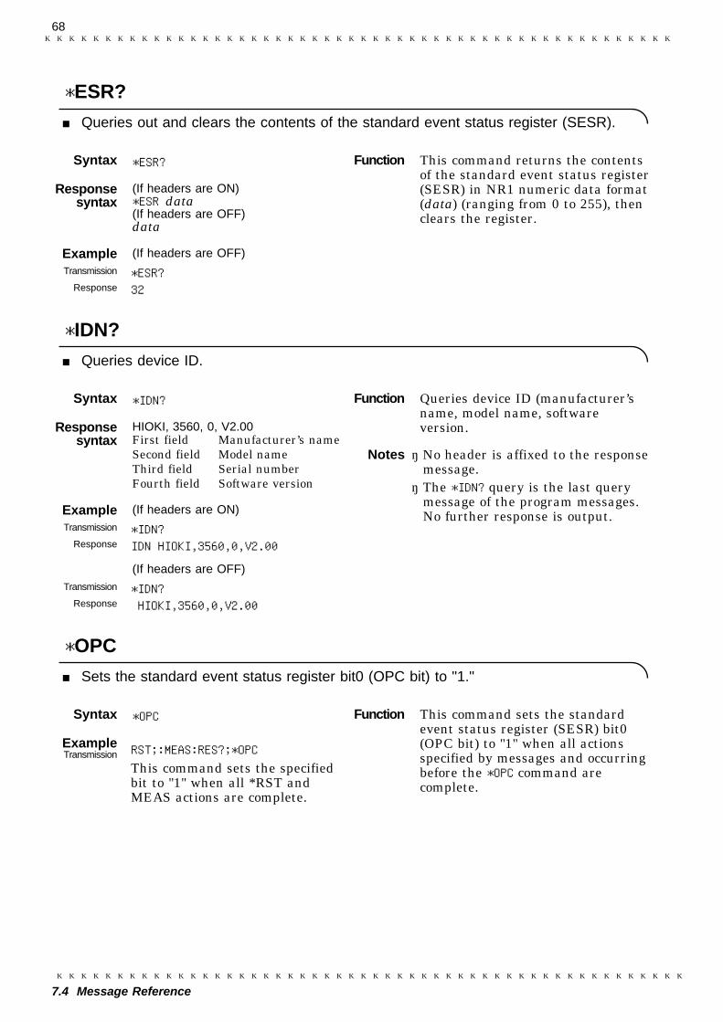
68
7.4 Message Reference
Syntax *ESR?
Responsesyntax
(If headers are ON)*ESR data(If headers are OFF)data
Example (If headers are OFF)Transmission *ESR?
Response 32
Syntax *IDN?
Responsesyntax
HIOKI, 3560, 0, V2.00First field Manufacturer’s nameSecond field Model nameThird field Serial numberFourth field Software version
Example (If headers are ON)Transmission *IDN?
Response IDN HIOKI,3560,0,V2.00
(If headers are OFF)Transmission *IDN?
Response HIOKI,3560,0,V2.00
Syntax *OPC
ExampleTransmission RST;:MEAS:RES?;*OPC
This command sets the specifiedbit to "1" when all *RST andMEAS actions are complete.
Function This command returns the contentsof the standard event status register(SESR) in NR1 numeric data format(data) (ranging from 0 to 255), thenclears the register.
Function Queries device ID (manufacturer’sname, model name, softwareversion.
Notes ・ No header is affixed to the responsemessage.・ The *IDN? query is the last query
message of the program messages.No further response is output.
Function This command sets the standardevent status register (SESR) bit0(OPC bit) to "1" when all actionsspecified by messages and occurringbefore the *OPC command arecomplete.
*ESR?
Queries out and clears the contents of the standard event status register (SESR).
*IDN?
Queries device ID.
*OPC
Sets the standard event status register bit0 (OPC bit) to "1."
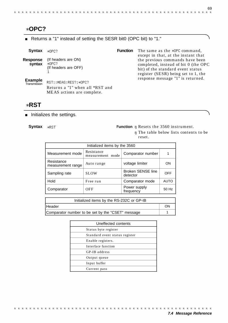
69
7.4 Message Reference
Syntax *OPC?
Responsesyntax
(If headers are ON)*OPC?(If headers are OFF)1
ExampleTransmission RST;:MEAS:RES?;*OPC?
Returns a "1" when all *RST andMEAS actions are complete.
Syntax *RST
Function The same as the *OPC command,except in that, at the instant thatthe previous commands have beencompleted, instead of bit 0 (the OPCbit) of the standard event statusregister (SESR) being set to 1, theresponse message "1" is returned.
Function ・ Resets the 3560 instrument.・ The table below lists contents to be
reset.
*OPC?
Returns a "1" instead of setting the SESR bit0 (OPC bit) to "1."
*RST
Initializes the settings.
Initialized items by the 3560
Measurement mode Resistancemeasurement mode Comparator number 1
Resistancemeasurement range Auto range voltage limiter ON
Sampling rate SLOW Broken SENSE linedetector OFF
Hold Free run Comparator mode AUTO
Comparator OFF Power supplyfrequency 50 Hz
Uneffected contents
Status byte register
Standard event status register
Enable registers.
Interface function
GP-IB address
Output queue
Input buffer
Current pass
Initialized items by the RS-232C or GP-IB
Header ON
Comparator number to be set by the "CSET" message 1
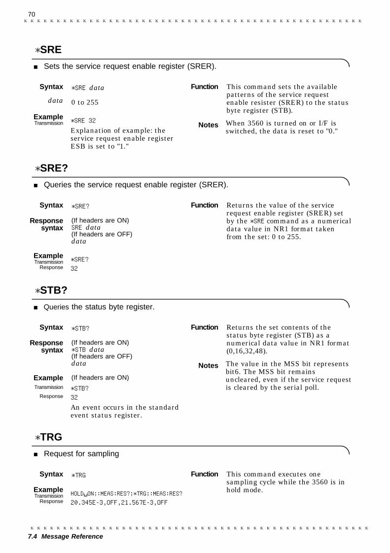
70
7.4 Message Reference
Syntax *SRE data
data 0 to 255
ExampleTransmission *SRE 32
Explanation of example: theservice request enable registerESB is set to "1."
Syntax *SRE?
Responsesyntax
(If headers are ON)SRE data(If headers are OFF)data
ExampleTransmission *SRE?
Response 32
Syntax *STB?
Responsesyntax
(If headers are ON)*STB data(If headers are OFF)data
Example (If headers are ON)Transmission *STB?
Response 32An event occurs in the standardevent status register.
Syntax *TRG
ExampleTransmission HOLD ON;:MEAS:RES?;*TRG;:MEAS:RES?
Response 20.345E-3,OFF,21.567E-3,OFF
Function This command sets the availablepatterns of the service requestenable resister (SRER) to the statusbyte register (STB).
Notes When 3560 is turned on or I/F isswitched, the data is reset to "0."
Function Returns the value of the servicerequest enable register (SRER) setby the *SRE command as a numericaldata value in NR1 format takenfrom the set: 0 to 255.
Function Returns the set contents of thestatus byte register (STB) as anumerical data value in NR1 format(0,16,32,48).
Notes The value in the MSS bit representsbit6. The MSS bit remainsuncleared, even if the service requestis cleared by the serial poll.
Function This command executes onesampling cycle while the 3560 is inhold mode.
*SRE
Sets the service request enable register (SRER).
*SRE?
Queries the service request enable register (SRER).
*STB?
Queries the status byte register.
*TRG
Request for sampling
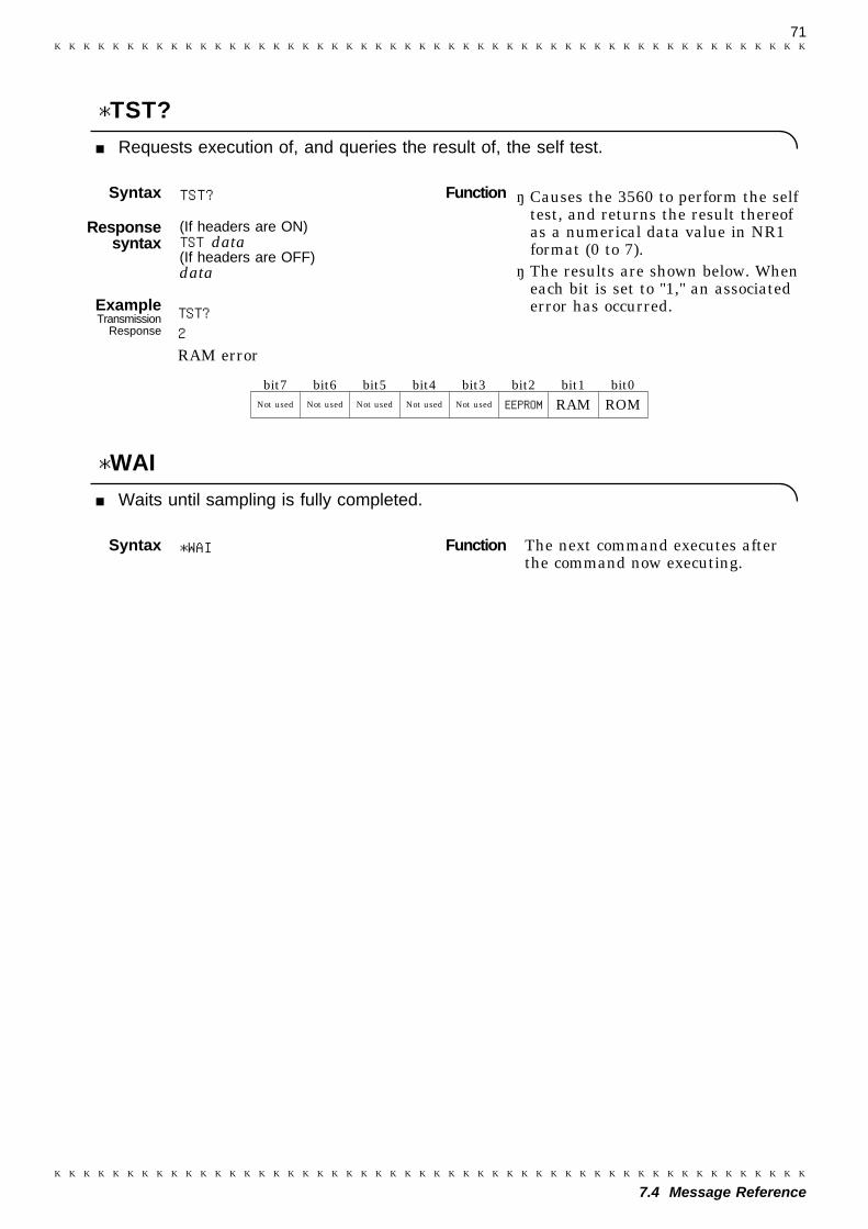
71
7.4 Message Reference
Syntax TST?
Responsesyntax
(If headers are ON)TST data(If headers are OFF)data
ExampleTransmission TST?
Response 2RAM error
Syntax *WAI
Function ・ Causes the 3560 to perform the selftest, and returns the result thereofas a numerical data value in NR1format (0 to 7).・ The results are shown below. When
each bit is set to "1," an associatederror has occurred.
Function The next command executes afterthe command now executing.
*TST?
Requests execution of, and queries the result of, the self test.
bit7 bit6 bit5 bit4 bit3 bit2 bit1 bit0Not used Not used Not used Not used Not used EEPROM RAM ROM
*WAI
Waits until sampling is fully completed.

72
7.4 Message Reference
Syntax :ADJust?
Responsesyntax
(If headers are ON):ADJUST data(If headers are OFF)data
Example (If headers are ON)Transmission :ADJ?
Response :ADJUST 0
(If headers are OFF)Transmission :ADJ?
Response 0The zero-adjust executessuccessfully.
Syntax :AUTOrange data
data ON/OFF (Character data)
ExampleTransmission :AUTO ON
The measurement is performed inauto-range mode.
Function This command executes a zero-adjust and returns a result in 0/1NR1 numeric data (data) format.If "data = 0," the zero-adjust executes correctly.If "data = 1," the zero-adjust does not executecorrectly.
Notes The zero-adjust cannot be performedin the following cases:A zero-adjust is attempted when thefollowing parameters exceed thespecified limits:Resistance function
240 dgt. (FAST mode)2400 dgt. (MEDIUM/SLOW mode)
Voltage function3400 dgt. (full sampling)Abnormal measurements
Function This command turns auto range onor off.
Notes Setting only resistance range or onlyvoltage range is not permitted.
7.4.2 Specific Command Messages
:ADJust?
Executes zero-adjust and queries the result.
:AUTOrange
Sets the auto range.
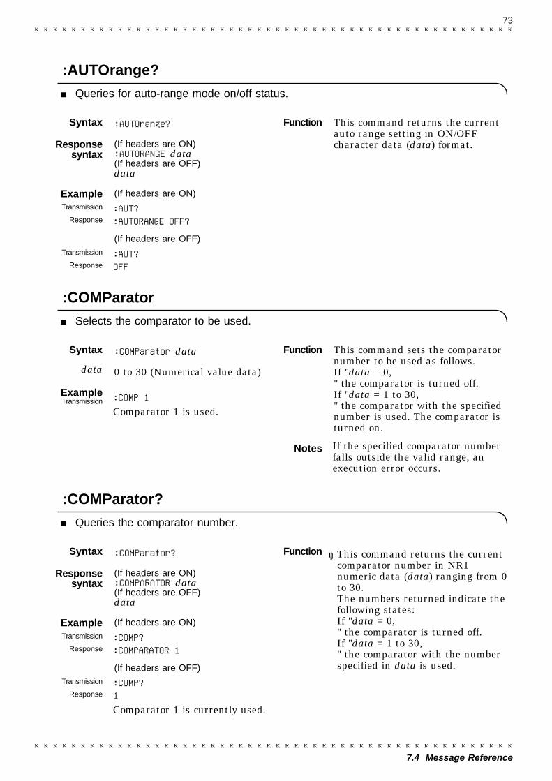
73
7.4 Message Reference
Syntax :AUTOrange?
Responsesyntax
(If headers are ON):AUTORANGE data(If headers are OFF)data
Example (If headers are ON)Transmission :AUT?
Response :AUTORANGE OFF?
(If headers are OFF)Transmission :AUT?
Response OFF
Syntax :COMParator data
data 0 to 30 (Numerical value data)
ExampleTransmission :COMP 1
Comparator 1 is used.
Syntax :COMParator?
Responsesyntax
(If headers are ON):COMPARATOR data(If headers are OFF)data
Example (If headers are ON)Transmission :COMP?
Response :COMPARATOR 1
(If headers are OFF)Transmission :COMP?
Response 1Comparator 1 is currently used.
Function This command returns the currentauto range setting in ON/OFFcharacter data (data) format.
Function This command sets the comparatornumber to be used as follows.If "data = 0," the comparator is turned off.If "data = 1 to 30," the comparator with the specifiednumber is used. The comparator isturned on.
Notes If the specified comparator numberfalls outside the valid range, anexecution error occurs.
Function ・ This command returns the currentcomparator number in NR1numeric data (data) ranging from 0to 30.The numbers returned indicate thefollowing states:If "data = 0," the comparator is turned off.If "data = 1 to 30," the comparator with the numberspecified in data is used.
:AUTOrange?
Queries for auto-range mode on/off status.
:COMParator
Selects the comparator to be used.
:COMParator?
Queries the comparator number.
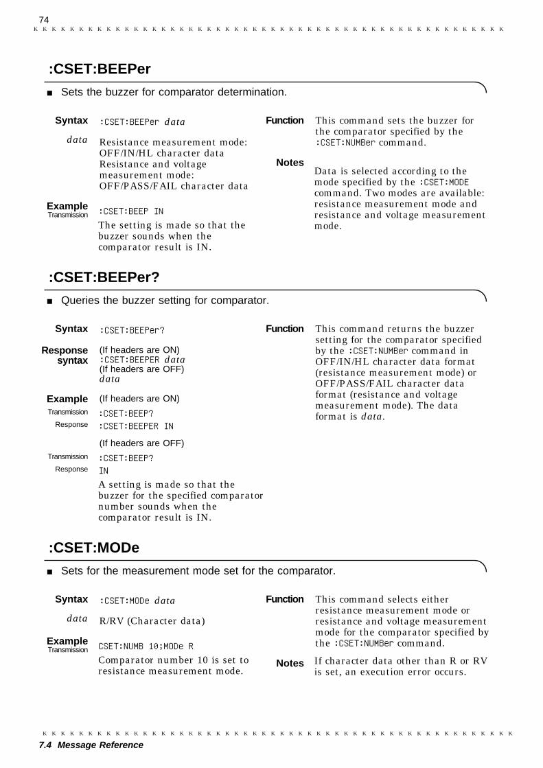
74
7.4 Message Reference
Syntax :CSET:BEEPer data
data Resistance measurement mode:OFF/IN/HL character dataResistance and voltagemeasurement mode:OFF/PASS/FAIL character data
ExampleTransmission :CSET:BEEP IN
The setting is made so that thebuzzer sounds when thecomparator result is IN.
Syntax :CSET:BEEPer?
Responsesyntax
(If headers are ON):CSET:BEEPER data(If headers are OFF)data
Example (If headers are ON)Transmission :CSET:BEEP?
Response :CSET:BEEPER IN
(If headers are OFF)Transmission :CSET:BEEP?
Response INA setting is made so that thebuzzer for the specified comparatornumber sounds when thecomparator result is IN.
Syntax :CSET:MODe data
data R/RV (Character data)
ExampleTransmission CSET:NUMB 10;MODe R
Comparator number 10 is set toresistance measurement mode.
Function This command sets the buzzer forthe comparator specified by the:CSET:NUMBer command.
NotesData is selected according to themode specified by the :CSET:MODEcommand. Two modes are available:resistance measurement mode andresistance and voltage measurementmode.
Function This command returns the buzzersetting for the comparator specifiedby the :CSET:NUMBer command inOFF/IN/HL character data format(resistance measurement mode) orOFF/PASS/FAIL character dataformat (resistance and voltagemeasurement mode). The dataformat is data.
Function This command selects eitherresistance measurement mode orresistance and voltage measurementmode for the comparator specified bythe :CSET:NUMBer command.
Notes If character data other than R or RVis set, an execution error occurs.
:CSET:BEEPer
Sets the buzzer for comparator determination.
:CSET:BEEPer?
Queries the buzzer setting for comparator.
:CSET:MODe
Sets for the measurement mode set for the comparator.

75
7.4 Message Reference
Syntax :CSET:MODe?
Responsesyntax
(If headers are ON):CSET:MODE data(If headers are OFF)data
Example (If headers are ON)Transmission :CSET:NUMB 20;MOD?
Response :CSET:MODE RV
(If headers are OFF)Transmission :CSET:NUMB 20;MOD?
Response RV
Syntax :CSET:NUMBer data
data 1 to 30 (Numerical value data)
ExampleTransmission :CSET:NUMBER 1
Comparator 1 is set.
Syntax :CSET:NUMBer?
Responsesyntax
(If headers are ON):CSET:NUMBER data(If headers are OFF)data
Example (If headers are ON)Transmission :CSET:NUMB?
Response :CSET:NUMBER 1
(If headers are OFF)Transmission :CSET:NUMB?
Response 1
Function ・ This command selects resistancemeasurement mode or resistanceand voltage measurement mode forthe comparator specified by the:CSET:NUMBer command.
Function This command is used to select thenumber of comparator to be set.
Notes If the set numeric data falls outsidethe range 1 to 30, an execution erroroccurs.
Function This command returns the currentlyset comparator number as a NR1value (1 to 30).
:CSET:MODe?
Queries for the measurement mode set for the comparator.
:CSET:NUMBer
Selects the number of comparator to be set.
:CSET:NUMBer?
Queries the number of comparator to be set.
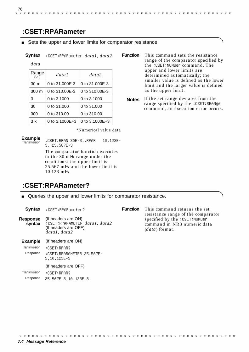
76
7.4 Message Reference
Syntax :CSET:RPARameter data1, data2
data
Range(Ω) data1 data2
30 m 0 to 31.000E-3 0 to 31.000E-3
300 m 0 to 310.00E-3 0 to 310.00E-3
3 0 to 3.1000 0 to 3.1000
30 0 to 31.000 0 to 31.000
300 0 to 310.00 0 to 310.00
3 k 0 to 3.1000E+3 0 to 3.1000E+3
*Numerical value data
ExampleTransmission :CSET:RRAN 30E-3;:RPAR 10.123E-
3, 25.567E-3The comparator function executesin the 30 mΩ range under theconditions: the upper limit is25.567 mΩ and the lower limit is10.123 mΩ.
Syntax :CSET:RPARameter?
Responsesyntax
(If headers are ON):CSET:RPARAMETER data1, data2(If headers are OFF)data1, data2
Example (If headers are ON)Transmission :CSET:RPAR?
Response :CSET:RPARAMETER 25.567E-3,10.123E-3
(If headers are OFF)Transmission :CSET:RPAR?
Response 25.567E-3,10.123E-3
Function This command sets the resistancerange of the comparator specified bythe :CSET:NUMBer command. Theupper and lower limits aredetermined automatically; thesmaller value is defined as the lowerlimit and the larger value is definedas the upper limit.
Notes If the set range deviates from therange specified by the :CSET:RRANgecommand, an execution error occurs.
Function This command returns the setresistance range of the comparatorspecified by the :CSET:NUMBercommand in NR3 numeric data(data) format.
:CSET:RPARameter
Sets the upper and lower limits for comparator resistance.
:CSET:RPARameter?
Queries the upper and lower limits for comparator resistance.

77
7.4 Message Reference
Syntax :CSET:RRANge data
data 0.03,0.3,3,30,300,3000(Numerical value data)
ExampleTransmission :CSET:RRAN 0.03
The 30 mΩ range is selected inthe comparator setting.
Syntax :CSET:RRANge?
Responsesyntax
(If headers are ON):CSET:RRANGE data(If headers are OFF)data
Example (If headers are ON)Transmission :CSET:RRAN?
Response :CSET:RRANGE 0.03
(If headers are OFF)Transmission :CSET:RRAN?
Response 0.03
Function This command sets the resistancerange for the comparator specified bythe :CSET:NUMBer command.
Notes If numeric data is not specified, anexecution error occurs.
Function This command returns the setresistance range of the comparatorspecified by the :CSET:NUMBercommand in NR3 numeric data(data) format
Range (Ω) data30m 30E-3
300m 300E-3
3 3E+0
30 30E+0
300 300E+0
3k 3E+3
:CSET:RRANge
Sets the resistance range used by the comparator.
:CSET:RRANge?
Sets the resistance range used by the comparator.
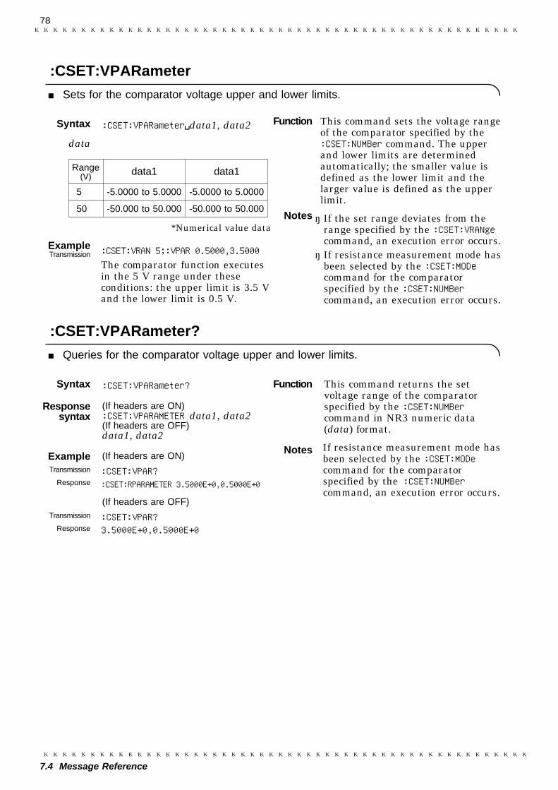
78
7.4 Message Reference
Syntax :CSET:VPARameter data1, data2
data
Range(V) data1 data1
5 -5.0000 to 5.0000 -5.0000 to 5.0000
50 -50.000 to 50.000 -50.000 to 50.000
*Numerical value data
ExampleTransmission :CSET:VRAN 5;:VPAR 0.5000,3.5000
The comparator function executesin the 5 V range under theseconditions: the upper limit is 3.5 Vand the lower limit is 0.5 V.
Syntax :CSET:VPARameter?
Responsesyntax
(If headers are ON):CSET:VPARAMETER data1, data2(If headers are OFF)data1, data2
Example (If headers are ON)Transmission :CSET:VPAR?
Response :CSET:RPARAMETER 3.5000E+0,0.5000E+0
(If headers are OFF)Transmission :CSET:VPAR?
Response 3.5000E+0,0.5000E+0
Function This command sets the voltage rangeof the comparator specified by the:CSET:NUMBer command. The upperand lower limits are determinedautomatically; the smaller value isdefined as the lower limit and thelarger value is defined as the upperlimit.
Notes ・ If the set range deviates from therange specified by the :CSET:VRANgecommand, an execution error occurs.・ If resistance measurement mode has
been selected by the :CSET:MODecommand for the comparatorspecified by the :CSET:NUMBercommand, an execution error occurs.
Function This command returns the setvoltage range of the comparatorspecified by the :CSET:NUMBercommand in NR3 numeric data(data) format.
Notes If resistance measurement mode hasbeen selected by the :CSET:MODecommand for the comparatorspecified by the :CSET:NUMBercommand, an execution error occurs.
:CSET:VPARameter
Sets for the comparator voltage upper and lower limits.
:CSET:VPARameter?
Queries for the comparator voltage upper and lower limits.

79
7.4 Message Reference
Syntax :CSET:VRANge data
data -50 to 50 (Numerical value data)
ExampleTransmission :CSET:VRAN 5
The 5 V range is selected in thecomparator setting.
Syntax :CSET:VRANge?
Responsesyntax
(If headers are ON):CSET:VRANGE data(If headers are OFF)data
Example (If headers are ON)Transmission :CSET:VRAN?
Response :CSET:VRANGE 5E+0
(If headers are OFF)Transmission :CSET:VRAN?
Response 5E+0
Syntax :CTMode data
data AUTO/MANUal (Character data)
ExampleTransmission :CTM AUT
The external control terminalmode is set to AUTO.
Function This command sets the voltagerange of the comparator specified bythe :CSET:NUMBer command.
Notes ・ If numeric data is not specified, anexecution error occurs.・ If resistance measurement mode has
been selected by the :CSET:MODecommand for the comparatorspecified by the :CSET:NUMBercommand, an execution error occurs.
Function This command returns the setvoltage range of the comparatorspecified by the :CSET:NUMBercommand in NR3 numeric data(data) format.5 V range 5E+050 V range 50E+0
Notes If resistance measurement mode hasbeen selected by the :CSET:MODecommand for the comparatorspecified by the :CSET:NUMBercommand, an execution error occurs.
Function This command sets comparatormode to either of auto-comparatormode or manual comparator mode.
:CSET:VRANge
Sets for the voltage range used by the comparator.
:CSET:VRANge?
Queries for the voltage range used by the comparator.
:CTMode
Sets the comparator mode.

80
7.4 Message Reference
Syntax :CTMode?
Responsesyntax
(If headers are ON):CTMODE data(If headers are OFF)data
Example (If headers are ON)Transmission :CTM?
Response :CTMODE AUTO?
(If headers are OFF)Transmission :CTM?
Response AUTO
Syntax :FREQuenc data
data 50/60 (Numerical value data)
ExampleTransmission :FREQ 50
Power supply voltage is set to50Hz.
Syntax :FREQuency?
Responsesyntax
(If headers are ON):FREQUENCY data(If headers are OFF)data
Example (If headers are ON)Transmission :FREQ?
Response :FREQUENCY 50
(If headers are OFF)Transmission :FREQ?
Response 50
Function This command returns the setcomparator mode inAUTO/MANUAL character data(data) format.
Function Sets power supply voltage.
Notes When the power supply frequencydata is not 50 Hz or 60 Hz, thiscommand rounds it off to 50 Hz or60 Hz.
FunctionThis command returns the currentpower supply voltage setting in50/60 numeric data (data) format.
:CTMode?
Queries the comparator mode.
:FREQuency
This command sets power supply voltage.
:FREQuency?
This command queries power supply voltage.
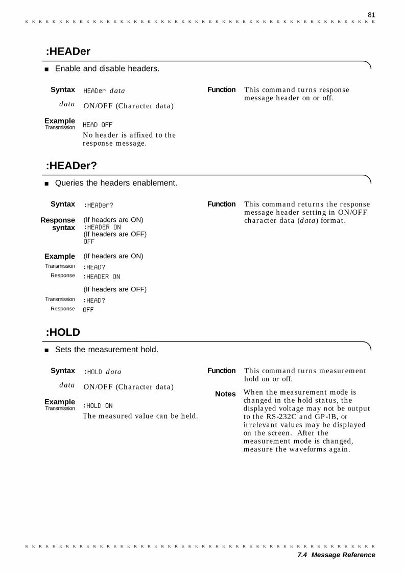
81
7.4 Message Reference
Syntax HEADer data
data ON/OFF (Character data)
ExampleTransmission HEAD OFF
No header is affixed to theresponse message.
Syntax :HEADer?
Responsesyntax
(If headers are ON):HEADER ON(If headers are OFF)OFF
Example (If headers are ON)Transmission :HEAD?
Response :HEADER ON
(If headers are OFF)Transmission :HEAD?
Response OFF
Syntax :HOLD data
data ON/OFF (Character data)
ExampleTransmission :HOLD ON
The measured value can be held.
Function This command turns responsemessage header on or off.
Function This command returns the responsemessage header setting in ON/OFFcharacter data (data) format.
Function This command turns measurementhold on or off.
Notes When the measurement mode ischanged in the hold status, thedisplayed voltage may not be outputto the RS-232C and GP-IB, orirrelevant values may be displayedon the screen. After themeasurement mode is changed,measure the waveforms again.
:HEADer
Enable and disable headers.
:HEADer?
Queries the headers enablement.
:HOLD
Sets the measurement hold.
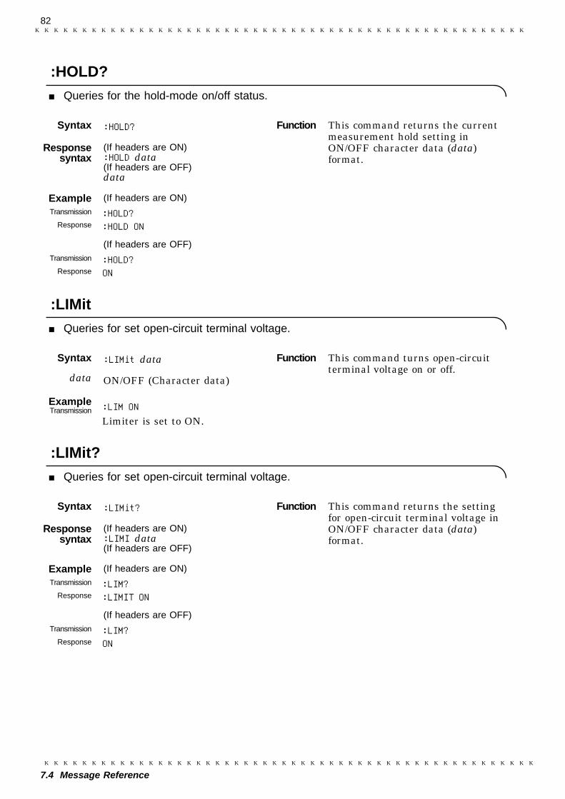
82
7.4 Message Reference
Syntax :HOLD?
Responsesyntax
(If headers are ON):HOLD data(If headers are OFF)data
Example (If headers are ON)Transmission :HOLD?
Response :HOLD ON
(If headers are OFF)Transmission :HOLD?
Response ON
Syntax :LIMit data
data ON/OFF (Character data)
ExampleTransmission :LIM ON
Limiter is set to ON.
Syntax :LIMit?
Responsesyntax
(If headers are ON):LIMI data(If headers are OFF)
Example (If headers are ON)Transmission :LIM?
Response :LIMIT ON
(If headers are OFF)Transmission :LIM?
Response ON
Function This command returns the currentmeasurement hold setting inON/OFF character data (data)format.
Function This command turns open-circuitterminal voltage on or off.
Function This command returns the settingfor open-circuit terminal voltage inON/OFF character data (data)format.
:HOLD?
Queries for the hold-mode on/off status.
:LIMit
Queries for set open-circuit terminal voltage.
:LIMit?
Queries for set open-circuit terminal voltage.
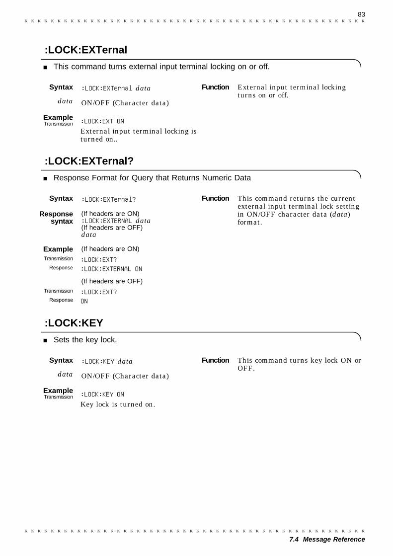
83
7.4 Message Reference
Syntax :LOCK:EXTernal data
data ON/OFF (Character data)
ExampleTransmission :LOCK:EXT ON
External input terminal locking isturned on..
Syntax :LOCK:EXTernal?
Responsesyntax
(If headers are ON):LOCK:EXTERNAL data(If headers are OFF)data
Example (If headers are ON)Transmission :LOCK:EXT?
Response :LOCK:EXTERNAL ON
(If headers are OFF)Transmission :LOCK:EXT?
Response ON
Syntax :LOCK:KEY data
data ON/OFF (Character data)
ExampleTransmission :LOCK:KEY ON
Key lock is turned on.
Function External input terminal lockingturns on or off.
Function This command returns the currentexternal input terminal lock settingin ON/OFF character data (data)format.
Function This command turns key lock ON orOFF.
:LOCK:EXTernal
This command turns external input terminal locking on or off.
:LOCK:EXTernal?
Response Format for Query that Returns Numeric Data
:LOCK:KEY
Sets the key lock.
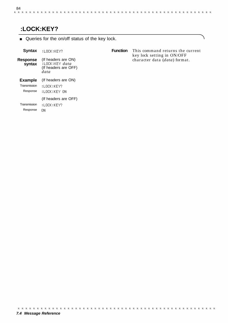
84
7.4 Message Reference
Syntax :LOCK:KEY?
Responsesyntax
(If headers are ON):LOCK:KEY data(If headers are OFF)data
Example (If headers are ON)Transmission :LOCK:KEY?
Response :LOCK:KEY ON
(If headers are OFF)Transmission :LOCK:KEY?
Response ON
Function This command returns the currentkey lock setting in ON/OFFcharacter data (data) format.
:LOCK:KEY?
Queries for the on/off status of the key lock.

85
7.4 Message Reference
Syntax :MEASure:BATTery?
Responsesyntax
(If headers are ON):MEASURE:BATTERY data1, data2(If headers are OFF)data1, data2
data1 Resistance
Resistancerange(Ω)
Sampling rate
FAST MEDIUM/SLOW
30 m .E-3 .E-3
300 m .E-3 .E-3
3 .E+0 .E+0
30 .E+0 .E+0
300 .E+0 .E+0
3 k .E+3 .E+3
OFF 1.0000E+8 1.0000E+8
NG 1.0000E+9 1.0000E+9
data2 Voltage
Voltage range(V)
All of sampling rate
5 ±.E+0
50 ±.E+0
OFF ±1.0000E+8
NG 1.0000E+9
data3 FAIL/PASS comparator resultsOFF comparator isnot usedNG Abnormal measurements
Example (If headers are ON)Transmission :MEAS:BATT?
Response :MEASURE:BATTERY 20.123E-3,3.5678E+0,PASS
(If headers are OFF)Transmission :MEAS:BATT?
Response 20.123E-3,3.5678E+0,PASS
Function ・ In resistance and voltagemeasurement mode, this commandreturns current measuredresistance and voltage in NR3numeric data format (data1 anddata2) and the comparator result inFAIL/PASS/OFF/NG character dataformat (data3).
Notes If resistance measurement mode isactive, an execution error occurs.
:MEASure:BATTery?
Queries for the current measured resistance and voltage and comparator result.

86
7.4 Message Reference
Syntax :MEASure:RESistance?
Responsesyntax
(If headers are ON):MEASURE:RESISTANCE data1, data2(If headers are OFF)data1, data2HI/IN/LO/FAIL/PASS comparatorresultsOFF Comparator is not used.NG Abnormal measurements
data1 Resistance
Resistancerange(Ω)
Sampling rate
FAST MEDIUM/SLOW
30 m .E-3 .E-3
300 m .E-3 .E-3
3 .E+0 .E+0
30 .E+0 .E+0
300 .E+0 .E+0
3 k .E+3 .E+3
OFF 1.0000E+8 1.0000E+8
NG 1.0000E+9 1.0000E+9
data2 HI/IN/LO/FAIL/PASS comparatorresultsOFF Comparator is not used.NG Abnormal measurements
Example (If headers are ON)Transmission :MEAS:RES?
Response :MEASURE:RESISTANCE 20.123E-3,IN
(If headers are OFF)Transmission :MEAS:RES?
Response 20.123E-3,IN
Function ・ This command returns the currentmeasured resistance in NR3numeric data format (data1), andthe comparator result inHI/IN/LO/OFF/NG character dataformat (data2) orFAIL/PASS/OFF/NG character dataformat (data2).・ HI/IN/LO is returned in voltage
measurement mode, whileFAIL/PASS is returned inresistance and voltagemeasurement mode.
:MEASure:RESistance?
Queries for the current measured resistance and comparator result.
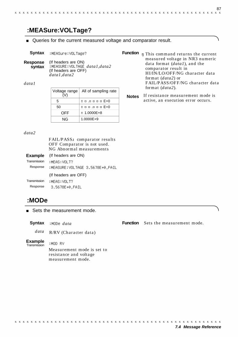
87
7.4 Message Reference
Syntax :MEASure:VOLTage?
Responsesyntax
(If headers are ON):MEASURE:VOLTAGE data1,data2(If headers are OFF)data1,data2
data1
Voltage range(V)
All of sampling rate
5 ±.E+0
50 ±.E+0
OFF ±1.0000E+8
NG 1.0000E+9
data2FAIL/PASS comparator resultsOFF Comparator is not used.NG Abnormal measurements
Example (If headers are ON)Transmission :MEAS:VOLT?
Response :MEASURE:VOLTAGE 3.5678E+0,FAIL
(If headers are OFF)Transmission :MEAS:VOLT?
Response 3.5678E+0,FAIL
Syntax :MODe data
data R/RV (Character data)
ExampleTransmission :MOD RV
Measurement mode is set toresistance and voltagemeasurement mode.
Function ・ This command returns the currentmeasured voltage in NR3 numericdata format (data1), and thecomparator result inHI/IN/LO/OFF/NG character dataformat (data2) orFAIL/PASS/OFF/NG character dataformat (data2).
Notes If resistance measurement mode isactive, an execution error occurs.
Function Sets the measurement mode.
:MEASure:VOLTage?
Queries for the current measured voltage and comparator result.
:MODe
Sets the measurement mode.
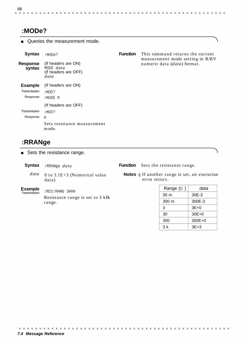
88
7.4 Message Reference
Syntax :MODe?
Responsesyntax
(If headers are ON)MODE data(If headers are OFF)data
Example (If headers are ON)Transmission :MOD?
Response :MODE R
(If headers are OFF)Transmission :MOD?
Response RSets resistance measurementmode.
Syntax :RRANge data
data 0 to 3.1E+3 (Numerical valuedata)
ExampleTransmission :RES:RANG 3000
Resistance range is set to 3 kΩrange.
Function This command returns the currentmeasurement mode setting in R/RVnumeric data (data) format.
Function Sets the resistance range.
Notes ・ If another range is set, an executionerror occurs.
Range (Ω) data30 m 30E-3
300 m 300E-3
3 3E+0
30 30E+0
300 300E+0
3 k 3E+3
:MODe?
Queries the measurement mode.
:RRANge
Sets the resistance range.
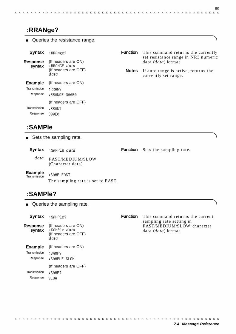
89
7.4 Message Reference
Syntax :RRANge?
Responsesyntax
(If headers are ON):RRANGE data(If headers are OFF)data
Example (If headers are ON)Transmission :RRAN?
Response :RRANGE 300E0
(If headers are OFF)Transmission :RRAN?
Response 300E0
Syntax :SAMPle data
data FAST/MEDIUM/SLOW(Character data)
ExampleTransmission :SAMP FAST
The sampling rate is set to FAST.
Syntax :SAMPle?
Responsesyntax
(If headers are ON):SAMPle data(If headers are OFF)data
Example (If headers are ON)Transmission :SAMP?
Response :SAMPLE SLOW
(If headers are OFF)Transmission :SAMP?
Response SLOW
Function This command returns the currentlyset resistance range in NR3 numericdata (data) format.
Notes If auto range is active, returns thecurrently set range.
Function Sets the sampling rate.
Function This command returns the currentsampling rate setting inFAST/MEDIUM/SLOW characterdata (data) format.
:RRANge?
Queries the resistance range.
:SAMPle
Sets the sampling rate.
:SAMPle?
Queries the sampling rate.

90
7.4 Message Reference
Syntax :SENSecheck data
data ON/OFF (Character data)
ExampleTransmission :SENS ON
Broken-line detection is turned onfor the SENSE line of themeasurement leads.
Syntax :SENSecheck?
Responsesyntax
(If headers are ON):SENSECHECK data(If headers are OFF)data
Example (If headers are ON)Transmission :SENS?
Response :SENSECHECK ON
(If headers are OFF)Transmission :SENS?
Response ON
Syntax :VRANge data
data -50 to 50 (Numerical value data)
ExampleTransmission :VRAN 5
Voltage range is set to 5 V range.
Function SENSE line break check formeasurement leads turns on or off.
Function This command returns the settingfor SENSE line break check formeasurement leads in ON/OFFcharacter data (data) format.
Function Sets the voltage range.
Notes ・ If another range is set, an executionerror occurs.・ If resistance measurement mode is
active, an execution error occurs.
:SENSecheck
Sets the SENSE line break check for measurement leads.
:SENSecheck?
Queries on/off status of the SENSE line break check for measurement leads.
:VRANge
Sets the voltage range.

91
7.4 Message Reference
Syntax :VRANge?
Responsesyntax
(If headers are ON):VRANGE data(If headers are OFF)data
Example (If headers are ON)Transmission :VRAN?
Response :VRANGE 50E+0
(If headers are OFF)Transmission :VRAN?
Response 50E+0
Syntax :ZERoclear
Example (If headers are ON)Transmission :ZER
The zero-clear is executed.
Function This command returns the currentlyset voltage range in NR3 numericdata (data) format.
Notes ・If resistance measurement mode isactive, an execution error occurs.・If auto range is active, returns the
currently set range.
Function Zero-clear is a function used toreturn the zero-adjust data to theirdefault values.
:VRANge?
Queries the voltage range.
:ZERoclear
Excuses zero clear.
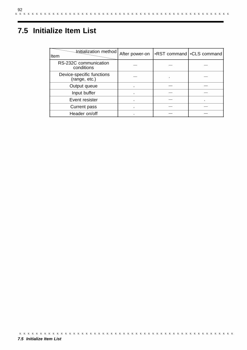
92
7.5 Initialize Item List
Initialization methodItem After power-on *RST command *CLS command
RS-232C communicationconditions
Device-specific functions(range, etc.)
Output queue
Input buffer
Event resister
Current pass
Header on/off
7.5 Initialize Item List
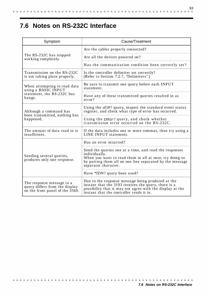
93
7.6 Notes on RS-232C Interface
Symptom Cause/Treatment
The RS-232C has stoppedworking completely.
Are the cables properly connected?
Are all the devices powered on?
Has the communication condition been correctly set?
Transmission on the RS-232Cis not taking place properly.
Is the controller delimiter set correctly?(Refer to Section 7.2.7, "Delimiters".)
When attempting to read datausing a BASIC INPUTstatement, the RS-232C bushangs.
Be sure to transmit one query before each INPUTstatement.
Have any of these transmitted queries resulted in aserror?
Although a command hasbeen transmitted, nothing hashappened.
Using the *ESR? query, inspect the standard event statusregister, and check what type of error has occurred.
Using the ERRor? query, and check whethertransmission error occurred on the RS-232C.
The amount of data read in isinsufficient.
If the data includes one or more commas, then try using aLINE INPUT statement.
Sending several queries,produces only one response.
Has an error occurred?
Send the queries one at a time, and read the responsesindividually.When you want to read them in all at once, try doing soby putting them all on one line separated by the messageseparator character.
Have *IDN? query been used?
The response message to aquery differs from the displayon the front panel of the 3560.
Due to the response message being produced at theinstant that the 3193 receives the query, there is apossibility that it may not agree with the display at theinstant that the controller reads it in.
7.6 Notes on RS-232C Interface

94
7.6 Notes on RS-232C Interface
95
1
2
3
4
5
6
7
8
9
10
11
12
13
14
A
SH1 All source handshake functionsAH1 All accepter handshake functions
T6
Basic talk functionsSerial poll functionTalk-only mode is not provided.The talker cancellation function with MLA (My Listen Address) is provided.
L4Basic listener functionListen-only mode is not provided.The listener cancellation function with MTA (My Talk Address) is provided.
SR1 All service request functionsRL1 All remote/local functionsPP0 Parallel polling is not provided.DC1 All device clear functionsDT1 All device trigger functionsC0 The controller function is not provided.
Chapter 8GP-IB Interface (Option)
Except for the power switch, all instrument functions can be performedby remote control through the optional GP-IB interface. The RS-232Cand optional GP-IB interfaces may not be used simultaneously. (That is,only one interface may be used at any one given time.) For moreinformation on selecting between the RS-232C or GP-IB interface, see thesection that describes setting the RS-232C interface. For moreinformation on selecting between the RS-232C or GP-IB interface, see thesection that describes Section 8.2 "Operating.Procedure (GP-IB)." Formore information on mounting the 9588 GP-IB interface, see Chapter 4"Measurement Procedure."Applicable standard: IEEE-488.1 1987Reference standard: IEEE-488.2 1987If the output queue is full, the 9588 issues a query error to clear it. The9588 does not support output queue clear and query error outputfunctions in the deadlock state, as defined in the IEEE-488.2 standard.(Deadlock state: Both input buffer and output queue are full, haltingfurther data processing.)
Connector
Use a 24-pin connector compatible with the IEEE-488 bus. Multiplestandard bus cables may be used.
Interface function
See the interface function table.Applicable code: ASCII code
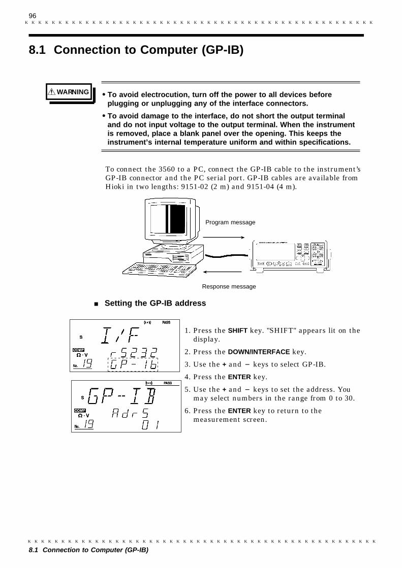
96
8.1 Connection to Computer (GP-IB)
WARNING To avoid electrocution, turn off the power to all devices beforeplugging or unplugging any of the interface connectors.
To avoid damage to the interface, do not short the output terminaland do not input voltage to the output terminal. When the instrumentis removed, place a blank panel over the opening. This keeps theinstrument’s internal temperature uniform and within specifications.
Response message
Program message
8.1 Connection to Computer (GP-IB)
To connect the 3560 to a PC, connect the GP-IB cable to the instrument’sGP-IB connector and the PC serial port. GP-IB cables are available fromHioki in two lengths: 9151-02 (2 m) and 9151-04 (4 m).
Setting the GP-IB address
1. Press the SHIFT key. "SHIFT" appears lit on thedisplay.
2. Press the DOWN/INTERFACE key.
3. Use the + and keys to select GP-IB.
4. Press the ENTER key.
5. Use the + and keys to set the address. Youmay select numbers in the range from 0 to 30.
6. Press the ENTER key to return to themeasurement screen.
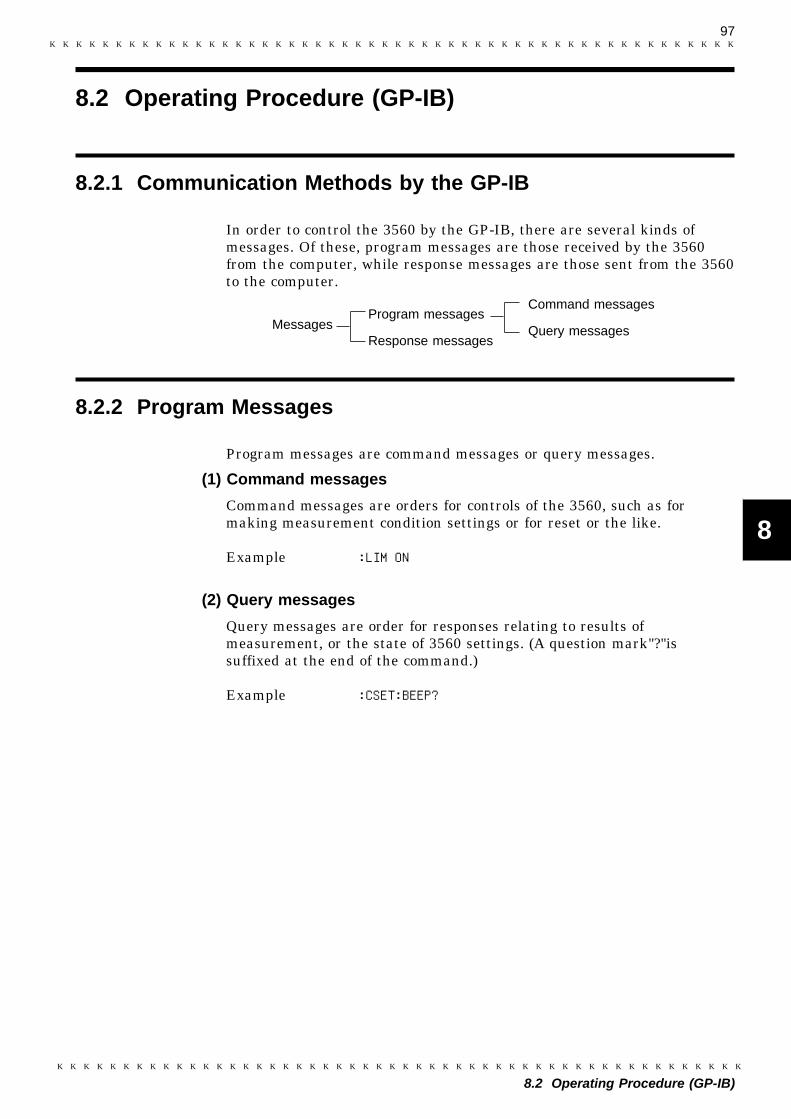
97
8.2 Operating Procedure (GP-IB)
1
2
3
4
5
6
7
8
9
10
11
12
13
14
A
8.2.1 Communication Methods by the GP-IB
Program messages
Response messages
Command messages
Query messagesMessages
8.2.2 Program Messages
8.2 Operating Procedure (GP-IB)
In order to control the 3560 by the GP-IB, there are several kinds ofmessages. Of these, program messages are those received by the 3560from the computer, while response messages are those sent from the 3560to the computer.
Program messages are command messages or query messages.
(1) Command messages
Command messages are orders for controls of the 3560, such as formaking measurement condition settings or for reset or the like.
Example :LIM ON
(2) Query messages
Query messages are order for responses relating to results ofmeasurement, or the state of 3560 settings. (A question mark"?"issuffixed at the end of the command.)
Example :CSET:BEEP?
98
8.2 Operating Procedure (GP-IB)
8.2.3 Message Format
NOTE
The commands for the 3560 are as far as possible mnemonic.Furthermore, all commands have a long form, and an abbreviated shortform.
(1) Program message
The program message is made up from header and data portions.
Example :AUT ONAUT: HeaderON: Data(ASCII codes or numerical characters. Messages containing no data also exist inthe form of query messages.)
A command header can be abbreviated. The whole command form isreferred to as the "long form" and the abbreviated from as the "shortform."In this manual, the short form is written in upper case letters, and thenthis is continued in lower case letters so as to constitute the long form.Either of these forms will be accepted during operation, but intermediateforms will not be accepted. Further, during operation both lower caseletters will be accepted without distinction.
(2) Response messages
It represents the response message for query messages from the 3560.Response messages generated by the 3560 are in long form and in uppercase letters.
Example :CSET:BEEPER IN
If an error occurs when a query is received, no response message to thequery is sent.
99
8.2 Operating Procedure (GP-IB)
1
2
3
4
5
6
7
8
9
10
11
12
13
14
A
8.2.4 Headers
(1) Program message headers
The program message always requires a header.These are three types of header: simple headers, compound headers, andparticular headers.
Simple header
A header consisting of a single word beginning with a letter.
Example :AUTorange
Compound header
A header consisting of a sequence of words separated by colons.
Example LOCK:KEYParticular header
A header beginning with an asterisk (*) to indicate that it is a particularcommand.
Example *CLS
(2) response message
Headers in response message can be enabled or disabled by using the"HEADer" command.Example "CSET:BEEP?" (Queries the buzzer setting)Response: [If headers are ON] :CSET:BEEPERINResponse: [If headers are OFF] IN (Data only)
100
8.2 Operating Procedure (GP-IB)
8.2.5 Data Formats
The 3560 use character string data and decimal numeric data, and thetype used varies according to the command in question.
(1) Character data
Character string data must always being with an alphabetic character,and the characters following can be either alphabetic characters ornumerals. Although in character data either upper case letters or lowercase letters are accepted, response messages output by the 3560 arealways in upper case letters.
Example :LIMIT ON
(2) Decimal data
The numeric data values are all represented in decimal, in three formatsidentified as NR1, NR2 and NR3, and each of these can appear as eithera signed number or an unsigned number. Unsigned numbers are taken aspositive.Further, if the accuracy of a numerical value exceeds the limit which the3560 can deal, it is rounded off. (5 and above is rounded up; 4 and belowis rounded down).
NR1 format - integer data.
Example +3000, -50000, 210NR2 format - fixed point numbers.
Example +2.56, -30.45, 300.28NR3 format - floating point numbers.
Example +3E-2, -1.2E+3
The term "NRf format" includes all these three formats.When the 3560 is receiving it accepts NRf format, but when it is sendingresponse messages it utilizes whichever one of the formats NR1 to NR3 isindicated in the specified command.Example :VRAN 5 :VRAN 5.01 :VRAN 0.05E2
101
8.2 Operating Procedure (GP-IB)
8.2.6 Delimiters
NOTE
8.2.7 Separators
NOTE
The term "delimiter" is used to refer to the following two possibilities forseparating data sequences.
EOICRCR + EOILFLF + EOICR + LFCR + LF + EOI
The response message delimiter has the following format:CR + LF + EOI
The 3560 analyzes the message after checking the delimiter. When usingan NEC PC-9801-series computer (and its GP-IB board) as a controller,first execute the "CMD DELIM=0" command to set the delimiter to "CR +LF."
(1) Message unit separator
A semicolon (;) is used as a message unit separator when it is desired toset out several messages on a single line.When message are combined in this way, if a syntax error occurs, allsubsequent messages up to the next delimiter will be ignored.Example :RRAN 3E-2;:VRAN 50;:MEAS:BATT
When message are combined in this way, if a syntax error occurs, allsubsequent messages up to the next delimiter will be ignored.
(2) Header separator
In a message which has a header and data, a apace (represented by ""(space) in the examples) is used as the header separator to separate theheader from the data.Example :COMPARATOR 1
(3) Data separator
If a message has several data items, commas (,) are required as dataseparators for separating these data items from one another.Example :CSET:RPAR data1,data2
102
8.2 Operating Procedure (GP-IB)
8.2.8 Abbreviation of Compound Commands
8.2.9 Output Queue
8.2.10 Input Buffer
When several compound headers have a common head portion (forexample, :CSET: ), then, when and only when writing them directlyfollowing on from one another, this common portion (:CSET: in thisexample) can be omitted.This common portion is called the "current path", by analogy with thegeneral concept of the current directly in the directly structure of UNIXor MSDOS, and until it is cleared the analysis of following commands isperformed by deeming them to be preceded by the current path is shownin the following example:
Normal expression:CSET:NUMBer;:CSET:RPARameter
Abbreviated expression:CSET:NUMBer;RPARameter
The current path is cleared when the power is turned on, when a colon (:)appears at the start of a command, and when delimiter is detected.
Messages with particular headers can be executed without relation to thecurrent path. Further, they have no effect upon the current path.While simple and complex command headers don’t require a colon ": "prefix, we recommend using the colon to avoid confusion with abbreviatedexpressions and to prevent 3560 malfunction.With the 3560, there are 3 possible current paths:":CSET, ":LOCK", ":MEAS"
Response messages accumulate in the output queue and all data arereceived and cleared.The output queue is also cleared in the following four situations:
When the instrument is powered on.When the Query error is occurred.When the Device is cleared.When the I/F is Switched.
The 3560 has an output queue of 128 byte capacity.If the responsemessages overflow this limit of 128 byte, a query error is generated, andthe output queue is cleared. Further, if a new message is received whilethe output queue still contains data, the output queue is cleared, and aquery error is generated.
The 3560 have an input buffer of 128 bytes capacity.
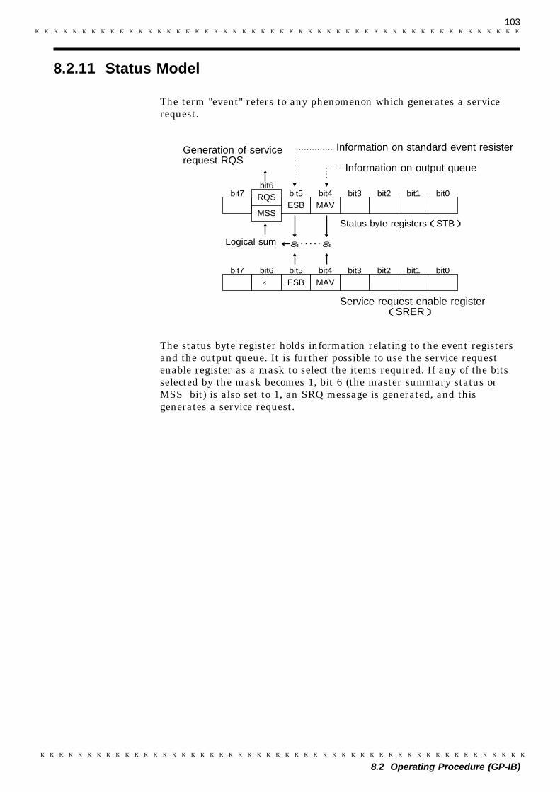
103
8.2 Operating Procedure (GP-IB)
8.2.11 Status Model
Logical sum
Generation of servicerequest RQS
MSS
RQSESB MAV
bit7bit6
bit5 bit4 bit3 bit2 bit1 bit0
&&
bit3 bit2 bit1 bit0ESB MAVbit5 bit4
×bit7 bit6
Status byte registers(STB)
Service request enable register(SRER)
Information on output queue
Information on standard event resister
The term "event" refers to any phenomenon which generates a servicerequest.
The status byte register holds information relating to the event registersand the output queue. It is further possible to use the service requestenable register as a mask to select the items required. If any of the bitsselected by the mask becomes 1, bit 6 (the master summary status orMSS bit) is also set to 1, an SRQ message is generated, and thisgenerates a service request.
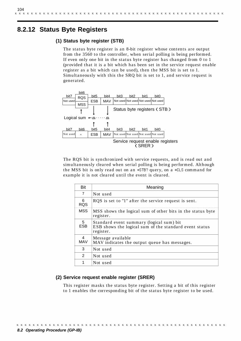
104
8.2 Operating Procedure (GP-IB)
8.2.12 Status Byte Registers
Not used
Not usedNot used
MSS
RQSESB MAV
bit7bit6
bit5 bit4 bit3 bit2 bit1 bit0
Logical sum &&
bit3 bit1 bit0ESB MAVbit5 bit4
Not used ×bit7 bit6
Status byte registers(STB)
Service request enable registers(SRER)
Not used Not used
Not used Not used Not usedNot used
bit2
Bit Meaning7 Not used6
RQSRQS is set to "1" after the service request is sent.
MSS MSS shows the logical sum of other bits in the status byteregister.
5ESB
Standard event summary (logical sum) bitESB shows the logical sum of the standard event statusregister.
4MAV
Message availableMAV indicates the output queue has messages.
3 Not used2 Not used1 Not used
(1) Status byte register (STB)
The status byte register is an 8-bit register whose contents are outputfrom the 3560 to the controller, when serial polling is being performed.If even only one bit in the status byte register has changed from 0 to 1(provided that it is a bit which has been set in the service request enableregister as a bit which can be used), then the MSS bit is set to 1.Simultaneously with this the SRQ bit is set to 1, and service request isgenerated.
The RQS bit is synchronized with service requests, and is read out andsimultaneously cleared when serial polling is being performed. Althoughthe MSS bit is only read out on an *STB? query, on a *CLS command forexample it is not cleared until the event is cleared.
(2) Service request enable register (SRER)
This register masks the status byte register. Setting a bit of this registerto 1 enables the corresponding bit of the status byte register to be used.
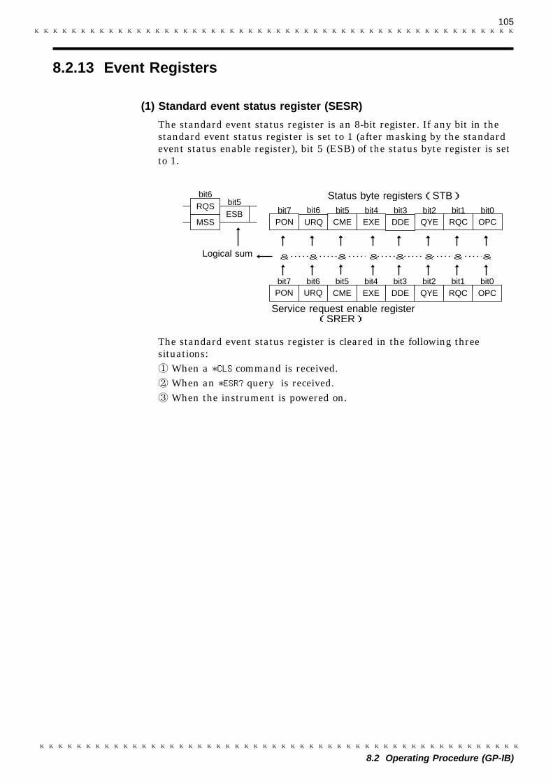
105
8.2 Operating Procedure (GP-IB)
8.2.13 Event Registers
bit2
DDEURQ CME EXEbit6 bit5 bit4 bit3
Logical sum &&
bit3 bit1CME EXEbit5 bit4
PON URQbit7 bit6
Status byte registers(STB)
Service request enable register(SRER)
DDE QYE RQC OPC
QYE RQC OPCPON
& & & &&&
ESBRQS
MSS
bit6bit5
bit7 bit2 bit1 bit0
bit0
(1) Standard event status register (SESR)
The standard event status register is an 8-bit register. If any bit in thestandard event status register is set to 1 (after masking by the standardevent status enable register), bit 5 (ESB) of the status byte register is setto 1.
The standard event status register is cleared in the following threesituations:
When a *CLS command is received.When an *ESR? query is received.When the instrument is powered on.

106
8.2 Operating Procedure (GP-IB)
Bit 7PON
Power-on flagPON is set to "1" when the 3560 is turned on or restored from apower failure.
Bit 6URQ
User requestThis bit is not used in the 3560.
Bit 5CME
Command error (Commands up to the message terminator areignored.)CME is set to "1" when the command received has the followingsyntax or interpretation errors:・ A command not defined in the 3560 is received.・ The program header is invalid.・ The data quantity differs from the specified value.・ The data format differs from that specified.
Bit 4EXE
Execution errorEXE is set to "1" when the command received cannot be executedbecause:・ The specified data deviates from the specified range.・ The specified data is not acceptable.
Bit 3DDE
Error resulting from device malfunction.DDE is set to "1" if the command cannot be executed for any reasonother than command, query, or execution errors.・ The command cannot be executed, due to an error within the 3560.・ The command cannot be executed, because another function is
already active.
Bit 2QYE
Query error (The output queue is cleared.)The query error is detected by the output queue controller and QYEset to "1" when the following events occur:・ An attempt is made to read an empty output queue.・ The response exceeds 128 bytes.・ The next message is received while the output queue contains data.・ A query exists after the *IDN? query on the same line.
Bit 1RQC
Controller privilege requestThis bit is not used in the 3560.
Bit 0OPC
Operation completeOPC is set to "1" when (for example) the *OPC command executes:* When all actions specified by messages up to the *OPC command are
complete
Register Read WriteStatus byte register *STB?
Service request enable register *SRE? *SRE
Standard event status register *ESR?
Standard event status enable register *ESE? *ESE
NOTE
(2) Standard event status enable register (SESER)
Setting any bit of the standard event status enable register to 1 enablesthe corresponding bit of the standard event status register to be accessed.
Standard event status resister
Register read/write command list
All adjustments made to the settings of the 3560 are stored in theinternal EEPROM, for which the number of write operations is limited.When the EEPROM reaches the end of its life, the error message "ERR-3"appears. 3560 is turned off or data is not correctly written due to a faultyEEPROM while the measurement conditions are being set in theEEPROM of the 3560.Contact your dealer or Hioki representative.

107
8.2 Operating Procedure (GP-IB)
8.2.14 GP-IB Command
Command Function
GTLGo To LocalThe remote state is canceled, and the system goes into thelocal state.
LLOLocal Lock OutAll keys, including the LOCAL key, becomes out ofoperating.
DCL Device ClearClears the input buffer and the output queue.
SDC Selected Device ClearClears the input buffer and the output queue.
GET Group Execute TriggerDuring the holding state, perform one-shot measurement.
NOTE
Interface functions permit use of the following commands:
Using the GET (GroupExecute Trigger) command in non-hold mode willproduce an execution error.The following items are the same as for the RS-232C interface. SeeChapter 7 "RS-232C Interface."Message Code TableCommon commandMessage referenceCommon commandMessagesInitialize Item List

108
8.3 Sample Program
100 DIM A$[100]110 DIM B$[100]120 CLEAR 701130 OUTPUT 701;"*RST"140 OUTPUT 701;"*IDN?"150 ENTER 701;A$160 PRINT A$170 OUTPUT 701;"*TST?"180 ENTER 701;B$190 PRINT B$200 END
8.3 Sample Program
The program shown below is described in HPBASIC which is created byusing the HP’s controller. For information on HPBASIC, refer to itsuser’s manual. All the messages in the sample program are described inshortened form. The GP-IB address of the 3560 is set to "1".
(1) 3560 inquiry program
This program initializes the 3560. It inquires to determine themanufacturer, model name, and software version. This program alsoexecutes the self test and inquires to determine the result.
Program list Program comments100 Defines character strings110 Defines character strings120 Initialize the interface130 Initialize the 3560140 Query device ID150 Get data160 Display data170 Execute and query self test180 Get data190 Display data200 End of program

109
8.3 Sample Program
100 DIM M$[10],S$[10],AR$[10]110 DIM A$[50],B$[50],C$[50],D$[50],E$[50]120 CLEAR 701130 INPUT"MODE? (R/RV) ";M$140 IF M$="R" THEN 160150 IF M$="RV" THEN 180160 OUTPUT 701;":MOD R"170 GOTO 190180 OUTPUT 701;":MOD RV")190 INPUT"SAMPLING? (F/M/S) ";S$200 IF S$="F" THEN 230210 IF S$="M" THEN 250220 IF S$="S" THEN 270230 OUTPUT 701;"SAMP FAST"240 GOTO 280250 OUTPUT 701;"SAMP MED"260 GOTO 280270 OUTPUT 701;"SAMP SLOW"280 INPUT"AUTORANGE? (A/M) ";Ar$290 IF Ar$="A" THEN 310300 IF Ar$="M" THEN 330310 OUTPUT 701;":AUT ON"320 GOTO 410330 OUTPUT 701;":AUT OFF"340 INPUT"RESISTANCE_RANGE? (0 - 3100) ";Rr350 IF Rr<0 OR Rr>3100 THEN 340360 OUTPUT 701;":RRAN ";Rr370 IF M$="R" THEN 410380 INPUT"VOLTAGE_RANGE? (-50 - 50) ";Vr390 IF Vr<-50 OR Vr>50 THEN 380400 OUTPUT 701;":VRAN ";Vr410 OUTPUT 701;":MOD?"420 ENTER 701;A$430 OUTPUT 701;":SAMP?"440 ENTER 701;B$450 OUTPUT 701;":AUT?"460 ENTER 701;C$470 OUTPUT 701;":RRAN?"480 ENTER 701;D$490 IF M$="R" THEN 540500 OUTPUT 701;":VRAN?"510 ENTER 701;E$520 PRINT A$,B$,C$,D$,E$530 GOTO 550540 PRINT A$,B$,C$,D$550 END
(2) 3560 measurement mode, sampling rate, and measurement rangesetup program
This program sets the measurement mode, sampling rate, andmeasurement range of the 3560, and inquires to determine theestablished settings.
100 Defines character strings110 Defines character strings120 Initialize the interface130 Specify the measurement mode140 Select the measurement mode150160 Set the measurement mode (Resistance mode)170180 Set the measurement mode (Resistance and
volatage mode)190 Specify the sampling rate200 Select the sampling rate210220230 Set the sampling rate to FAST240250 Set the sampling rate to MEDIUM260270 Set the sampling rate to SLOW280 Specify the auto range290 Select the range300310 Set the auto range to ON320330 Set the auto range to OFF340 Specify the resistance range350360 Set the resistance range370380 Specify the voltage range390400 Set the voltage range410 Query the measurement mode420 Get data430 Query the sampling rate440 Get data450 Query the autorange460 Get data470 Query the resistance range480 Get data490500 Query the voltage range510 Get data520 Display data (Resistance and voltage
measurement mode)530540 Display data (Resistance and voltage
measurement mode)550 End of program
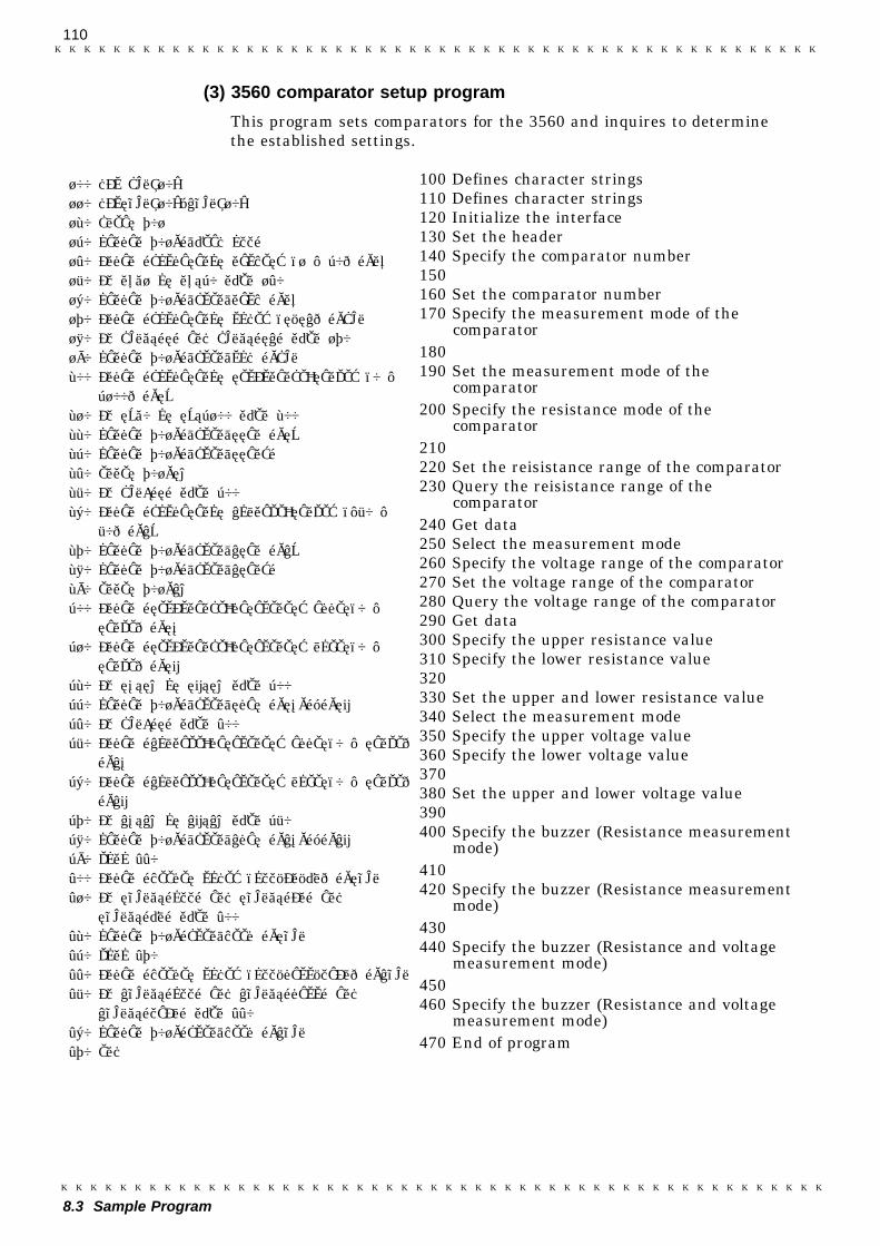
110
8.3 Sample Program
100 DIM Cm$[10]110 DIMRbm$[10],Vbm$[10]120 CLEAR 701130 OUTPUT 701;":HEAD OFF"140 INPUT "COMPARATOR NUMBER? (1 - 30) ";Nu150 IF Nu<1 OR Nu>30 THEN 140160 OUTPUT 701;":CSET:NUMB ";Nu170 INPUT "COMPARATOR MODE? (R/RV) ";Cm$180 IF Cm$<>"R" AND Cm$<>"RV" THEN 170190 OUTPUT 701;":CSET:MOD ";Cm$200 INPUT "COMPARATOR RESISTANCE_RANGE? (0 -3100) ";Rr
210 IF Rr<0 OR Rr>3100 THEN 200220 OUTPUT 701;":CSET:RRAN ";Rr230 OUTPUT 701;":CSET:RRAN?"240 ENTER 701;Rn250 IF Cm$="R" THEN 300260 INPUT "COMPARATOR VOLTAGE_RANGE? (-50 -50) ";Vr
270 OUTPUT 701;":CSET:VRAN ";Vr280 OUTPUT 701;":CSET:VRAN?"290 ENTER 701;Vn300 INPUT "RESISTANCE_PARAMETER? UPPER(0 -RANGE) ";Rh
310 INPUT "RESISTANCE_PARAMETER? LOWER(0 -RANGE) ";Rl
320 IF Rh>Rn OR Rl>Rn THEN 300330 OUTPUT 701;":CSET:RPAR ";Rh;",";Rl340 IF Cm$="R" THEN 400350 INPUT "VOLTAGE_PARAMETER? UPPER(0 - RANGE)";Vh
360 INPUT "VOLTAGE_PARAMETER? LOWER(0 - RANGE)";Vl
370 IF Vh>Vn OR Vl>Vn THEN 350380 OUTPUT 701;":CSET:VPAR ";Vh;",";Vl390 GOTO 440400 INPUT "BEEPER MODE? (OFF/IN/HL) ";Rbm$410 IF Rbm$<>"OFF" AND Rbm$<>"IN" ANDRbm$<>"HL" THEN 400
420 OUTPUT 701;"CSET:BEEP ";Rbm$430 GOTO 470440 INPUT "BEEPER MODE? (OFF/PASS/FAIL) ";Vbm$450 IF Vbm$<>"OFF" AND Vbm$<>"PASS" ANDVbm$<>"FAIL" THEN 440
460 OUTPUT 701;"CSET:BEEP ";Vbm$470 END
(3) 3560 comparator setup program
This program sets comparators for the 3560 and inquires to determinethe established settings.
100 Defines character strings110 Defines character strings120 Initialize the interface130 Set the header140 Specify the comparator number150160 Set the comparator number170 Specify the measurement mode of the
comparator180190 Set the measurement mode of the
comparator200 Specify the resistance mode of the
comparator210220 Set the reisistance range of the comparator230 Query the reisistance range of the
comparator240 Get data250 Select the measurement mode260 Specify the voltage range of the comparator270 Set the voltage range of the comparator280 Query the voltage range of the comparator290 Get data300 Specify the upper resistance value310 Specify the lower resistance value320330 Set the upper and lower resistance value340 Select the measurement mode350 Specify the upper voltage value360 Specify the lower voltage value370380 Set the upper and lower voltage value390400 Specify the buzzer (Resistance measurement
mode)410420 Specify the buzzer (Resistance measurement
mode)430440 Specify the buzzer (Resistance and voltage
measurement mode)450460 Specify the buzzer (Resistance and voltage
measurement mode)470 End of program
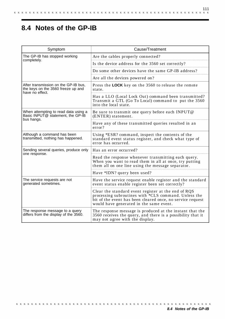
111
8.4 Notes of the GP-IB
Symptom Cause/Treatment
The GP-IB has stopped workingcompletely.
Are the cables properly connected?
Is the device address for the 3560 set correctly?
Do some other devices have the same GP-IB address?
Are all the devices powered on?
After transmission on the GP-IB bus,the keys on the 3560 freeze up andhave no effect.
Press the LOCK key on the 3560 to release the remotestate.
Has a LLO (Local Lock Out) command been transmitted?Transmit a GTL (Go To Local) command to put the 3560into the local state.
When attempting to read data using aBasic INPUT@ statement, the GP-IBbus hangs.
Be sure to transmit one query before each INPUT@(ENTER) statement.
Have any of these transmitted queries resulted in anerror?
Although a command has beentransmitted, nothing has happened.
Using *ESR? command, inspect the contents of thestandard event status register, and check what type oferror has occurred.
Sending several queries, produce onlyone response.
Has an error occurred?
Read the response whenever transmitting each query.When you want to read them in all at once, try puttingthem all on one line using the message separator.
Have *IDN? query been used?
The service requests are notgenerated sometimes.
Have the service request enable register and the standardevent status enable register been set correctly?
Clear the standard event register at the end of RQSprocessing subroutines with *CLS command. Unless thebit of the event has been cleared once, no service requestwould have generated in the same event.
The response message to a querydiffers from the display of the 3560.
The response message is produced at the instant that the3560 receives the query, and there is a possibility that itmay not agree with the display.
8.4 Notes of the GP-IB

112
8.4 Notes of the GP-IB
113
9.1 Outline
1
2
3
4
5
6
7
8
9
10
11
12
13
14
15
Chapter 9Printer Interface (Option)
9.1 Outline
After mounting an optional 9589 PRINTER INTERFACE to the 3560, youcan connect a 9203 DIGITAL PRINTER or general-purpose Centronicsprinter to print out measurement results. If the 9203 DIGITALPRINTER is connected, the 9203 can process the data statistically, andthe processed data can be printed out by the digital printer.This chapter explains how to connect a general-purpose Centronicsprinter to the 3560, and gives procedures for printing measurementresults.The 9203 DIGITAL PRINTER driver must be version 2.00 or laterpreferably later, as even version 2.00 will produce printer errors. Forupgrades, please contact the nearest Hioki sales representative. To findthe driver version number, please look in the printer operating manual.
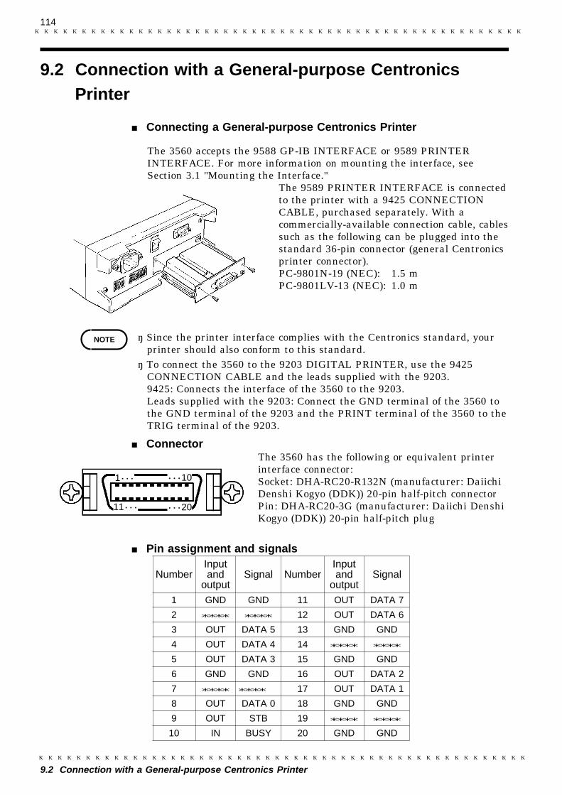
114
9.2 Connection with a General-purpose Centronics Printer
NOTE
1・・・ ・・・10
・・・2011・・・
NumberInputand
outputSignal Number
Inputand
outputSignal
1 GND GND 11 OUT DATA 7
2 **** **** 12 OUT DATA 6
3 OUT DATA 5 13 GND GND
4 OUT DATA 4 14 **** ****
5 OUT DATA 3 15 GND GND
6 GND GND 16 OUT DATA 2
7 **** **** 17 OUT DATA 1
8 OUT DATA 0 18 GND GND
9 OUT STB 19 **** ****
10 IN BUSY 20 GND GND
9.2 Connection with a General-purpose CentronicsPrinter
Connecting a General-purpose Centronics Printer
The 3560 accepts the 9588 GP-IB INTERFACE or 9589 PRINTERINTERFACE. For more information on mounting the interface, seeSection 3.1 "Mounting the Interface."
The 9589 PRINTER INTERFACE is connectedto the printer with a 9425 CONNECTIONCABLE, purchased separately. With acommercially-available connection cable, cablessuch as the following can be plugged into thestandard 36-pin connector (general Centronicsprinter connector).PC-9801N-19 (NEC): 1.5 mPC-9801LV-13 (NEC): 1.0 m
・ Since the printer interface complies with the Centronics standard, yourprinter should also conform to this standard.・ To connect the 3560 to the 9203 DIGITAL PRINTER, use the 9425
CONNECTION CABLE and the leads supplied with the 9203.9425: Connects the interface of the 3560 to the 9203.Leads supplied with the 9203: Connect the GND terminal of the 3560 tothe GND terminal of the 9203 and the PRINT terminal of the 3560 to theTRIG terminal of the 9203.
ConnectorThe 3560 has the following or equivalent printerinterface connector:Socket: DHA-RC20-R132N (manufacturer: DaiichiDenshi Kogyo (DDK)) 20-pin half-pitch connectorPin: DHA-RC20-3G (manufacturer: Daiichi DenshiKogyo (DDK)) 20-pin half-pitch plug
Pin assignment and signals
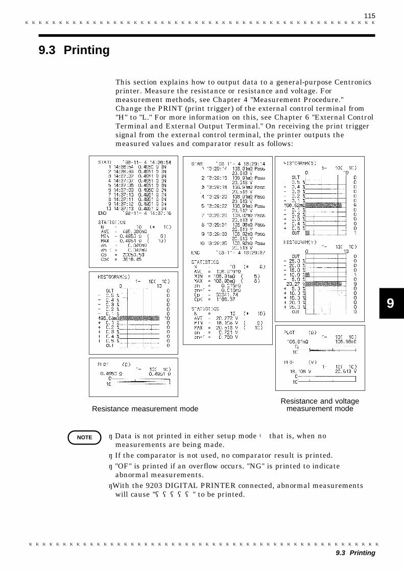
115
9.3 Printing
1
2
3
4
5
6
7
8
9
10
11
12
13
14
15
Resistance measurement modeResistance and voltage
measurement mode
NOTE
9.3 Printing
This section explains how to output data to a general-purpose Centronicsprinter. Measure the resistance or resistance and voltage. Formeasurement methods, see Chapter 4 "Measurement Procedure."Change the PRINT (print trigger) of the external control terminal from"H" to "L." For more information on this, see Chapter 6 "External ControlTerminal and External Output Terminal." On receiving the print triggersignal from the external control terminal, the printer outputs themeasured values and comparator result as follows:
・ Data is not printed in either setup mode - that is, when nomeasurements are being made.・ If the comparator is not used, no comparator result is printed.・ "OF" is printed if an overflow occurs. "NG" is printed to indicate
abnormal measurements.・With the 9203 DIGITAL PRINTER connected, abnormal measurements
will cause "―――――" to be printed.

116
9.3 Printing
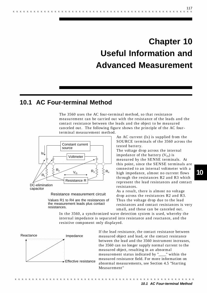
117
10.1 AC Four-terminal Method
1
2
3
4
5
6
7
8
9
10
11
12
13
14
15
R2
Is
DC-eliminationcapacitor
Constant currentsource
Voltmeter
Resistance R
Resistance measurement circuit
R1
VISR3 R4
Values R1 to R4 are the resistances ofthe measurement leads plus contactresistances.
Effective resistance
Reactance Impedance
Chapter 10Useful Information and
Advanced Measurement
10.1 AC Four-terminal Method
The 3560 uses the AC four-terminal method, so that resistancemeasurement can be carried out with the resistance of the leads and thecontact resistance between the leads and the object to be measuredcanceled out. The following figure shows the principle of the AC four-terminal measurement method.
An AC current (Is) is supplied from theSOURCE terminals of the 3560 across thetested battery.The voltage drop across the internalimpedance of the battery (VIS) ismeasured by the SENSE terminals. Atthis point, since the SENSE terminals areconnected to an internal voltmeter with ahigh impedance, almost no current flowsthrough the resistances R2 and R3 whichrepresent the lead resistances and contactresistances.As a result, there is almost no voltagedrop across the resistances R2 and R3.Thus the voltage drop due to the leadresistances and contact resistances is verysmall, and these can be canceled out.
In the 3560, a synchronized wave detection system is used, whereby theinternal impedance is separated into resistance and reactance, and theresistive component only displayed.
If the lead resistance, the contact resistance betweenmeasured object and lead, or the contact resistancebetween the lead and the 3560 instrument increases,the 3560 can no longer supply normal current to themeasured object, resulting in an abnormalmeasurement status indicated by "____" within themeasured resistance field. For more information onabnormal measurements, see Section 4.5 "StartingMeasurement"
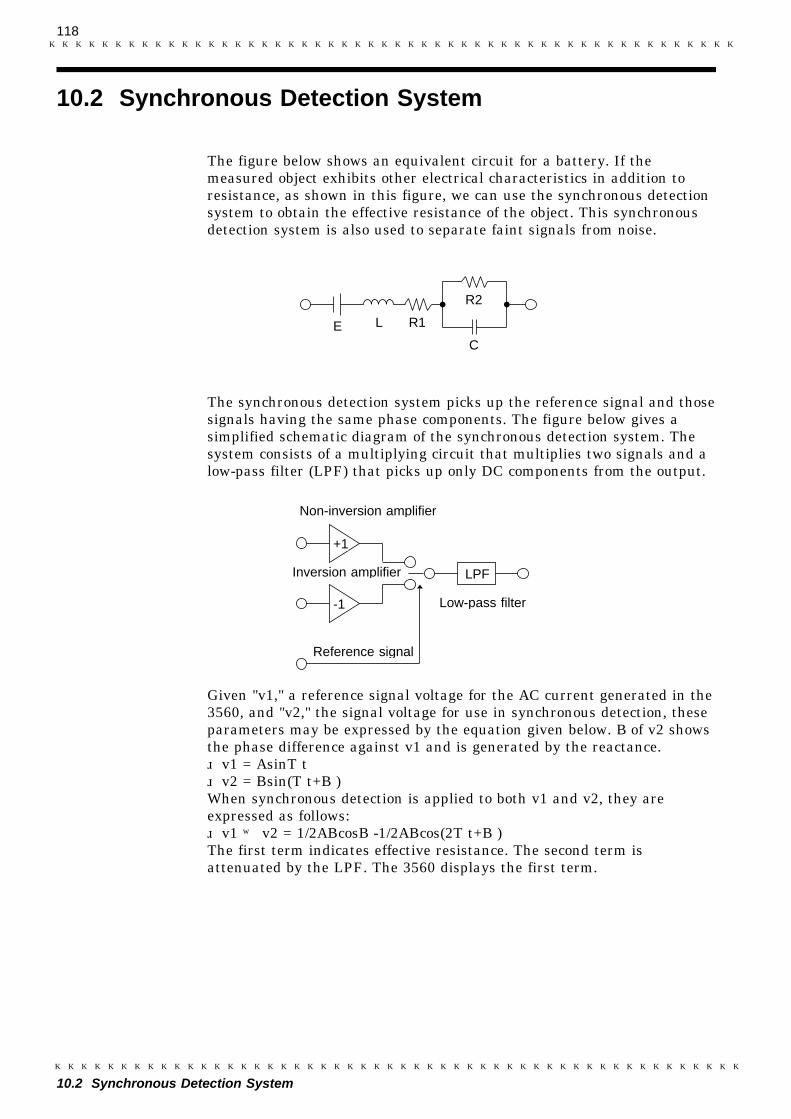
118
10.2 Synchronous Detection System
L
R2
C
R1E
Non-inversion amplifier
Inversion amplifier
Reference signal
-1 Low-pass filter
+1
LPF
10.2 Synchronous Detection System
The figure below shows an equivalent circuit for a battery. If themeasured object exhibits other electrical characteristics in addition toresistance, as shown in this figure, we can use the synchronous detectionsystem to obtain the effective resistance of the object. This synchronousdetection system is also used to separate faint signals from noise.
The synchronous detection system picks up the reference signal and thosesignals having the same phase components. The figure below gives asimplified schematic diagram of the synchronous detection system. Thesystem consists of a multiplying circuit that multiplies two signals and alow-pass filter (LPF) that picks up only DC components from the output.
Given "v1," a reference signal voltage for the AC current generated in the3560, and "v2," the signal voltage for use in synchronous detection, theseparameters may be expressed by the equation given below. θof v2 showsthe phase difference against v1 and is generated by the reactance. v1 = Asinωt v2 = Bsin(ωt+θ)When synchronous detection is applied to both v1 and v2, they areexpressed as follows: v1 × v2 = 1/2ABcosθ-1/2ABcos(2ωt+θ)The first term indicates effective resistance. The second term isattenuated by the LPF. The 3560 displays the first term.
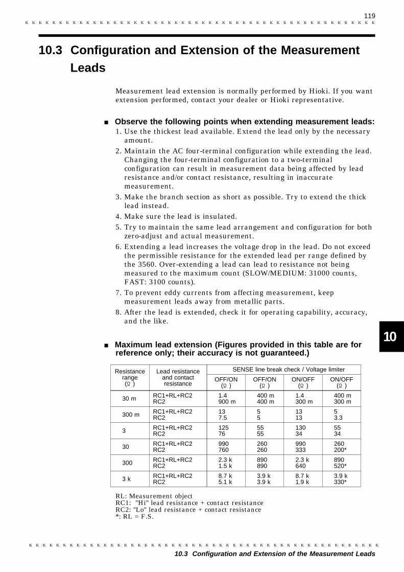
119
10.3 Configuration and Extension of the Measurement Leads
1
2
3
4
5
6
7
8
9
10
11
12
13
14
15
Resistancerange(Ω)
Lead resistanceand contactresistance
SENSE line break check / Voltage limiter
OFF/ON(Ω)
OFF/ON(Ω)
ON/OFF(Ω)
ON/OFF(Ω)
30 m RC1+RL+RC2RC2
1.4900 m
400 m400 m
1.4300 m
400 m300 m
300 m RC1+RL+RC2RC2
137.5
55
1313
53.3
3 RC1+RL+RC2RC2
12576
5555
13034
5534
30 RC1+RL+RC2RC2
990760
260260
990333
260200*
300 RC1+RL+RC2RC2
2.3 k1.5 k
890890
2.3 k640
890520*
3 k RC1+RL+RC2RC2
8.7 k5.1 k
3.9 k3.9 k
8.7 k1.9 k
3.9 k330*
10.3 Configuration and Extension of the MeasurementLeads
Measurement lead extension is normally performed by Hioki. If you wantextension performed, contact your dealer or Hioki representative.
Observe the following points when extending measurement leads:1. Use the thickest lead available. Extend the lead only by the necessary
amount.2. Maintain the AC four-terminal configuration while extending the lead.
Changing the four-terminal configuration to a two-terminalconfiguration can result in measurement data being affected by leadresistance and/or contact resistance, resulting in inaccuratemeasurement.
3. Make the branch section as short as possible. Try to extend the thicklead instead.
4. Make sure the lead is insulated.5. Try to maintain the same lead arrangement and configuration for both
zero-adjust and actual measurement.6. Extending a lead increases the voltage drop in the lead. Do not exceed
the permissible resistance for the extended lead per range defined bythe 3560. Over-extending a lead can lead to resistance not beingmeasured to the maximum count (SLOW/MEDIUM: 31000 counts,FAST: 3100 counts).
7. To prevent eddy currents from affecting measurement, keepmeasurement leads away from metallic parts.
8. After the lead is extended, check it for operating capability, accuracy,and the like.
Maximum lead extension (Figures provided in this table are forreference only; their accuracy is not guaranteed.)
RL: Measurement objectRC1: "Hi" lead resistance + contact resistanceRC2: "Lo" lead resistance + contact resistance*: RL = F.S.
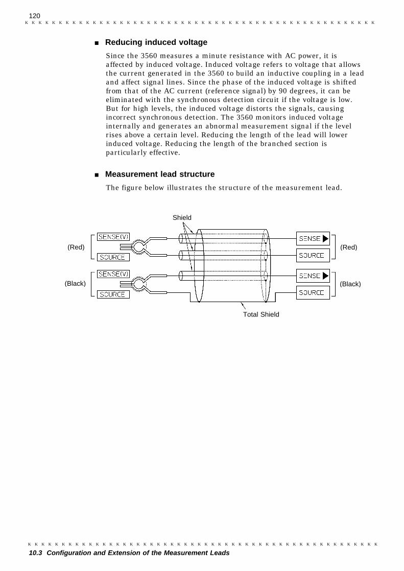
120
10.3 Configuration and Extension of the Measurement Leads
Shield
(Black)
(Red)
(Black)
(Red)
Total Shield
Reducing induced voltage
Since the 3560 measures a minute resistance with AC power, it isaffected by induced voltage. Induced voltage refers to voltage that allowsthe current generated in the 3560 to build an inductive coupling in a leadand affect signal lines. Since the phase of the induced voltage is shiftedfrom that of the AC current (reference signal) by 90 degrees, it can beeliminated with the synchronous detection circuit if the voltage is low.But for high levels, the induced voltage distorts the signals, causingincorrect synchronous detection. The 3560 monitors induced voltageinternally and generates an abnormal measurement signal if the levelrises above a certain level. Reducing the length of the lead will lowerinduced voltage. Reducing the length of the branched section isparticularly effective.
Measurement lead structure
The figure below illustrates the structure of the measurement lead.
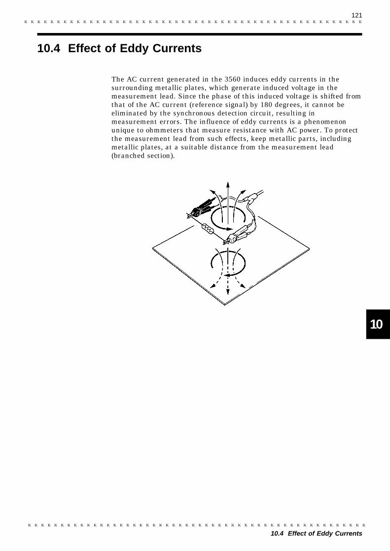
121
10.4 Effect of Eddy Currents
1
2
3
4
5
6
7
8
9
10
11
12
13
14
15
10.4 Effect of Eddy Currents
The AC current generated in the 3560 induces eddy currents in thesurrounding metallic plates, which generate induced voltage in themeasurement lead. Since the phase of this induced voltage is shifted fromthat of the AC current (reference signal) by 180 degrees, it cannot beeliminated by the synchronous detection circuit, resulting inmeasurement errors. The influence of eddy currents is a phenomenonunique to ohmmeters that measure resistance with AC power. To protectthe measurement lead from such effects, keep metallic parts, includingmetallic plates, at a suitable distance from the measurement lead(branched section).
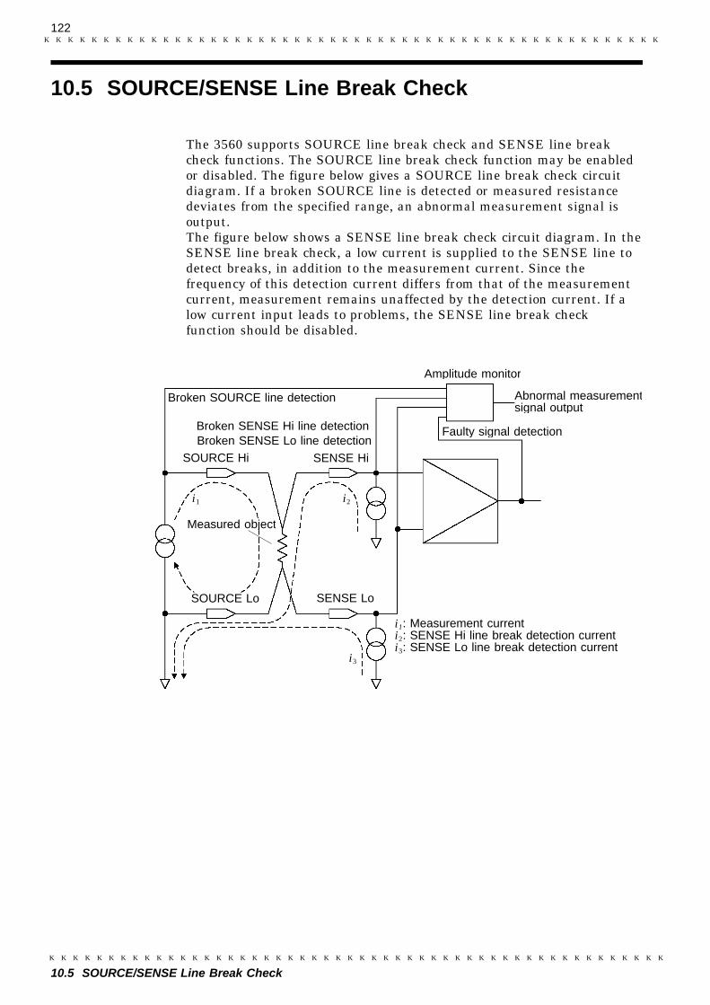
122
10.5 SOURCE/SENSE Line Break Check
Amplitude monitor
Broken SOURCE line detection
Broken SENSE Hi line detection
SOURCE Hi
Measured object
i3
Broken SENSE Lo line detection
SOURCE Lo SENSE Lo
SENSE Hi
i1 i2
Faulty signal detection
i1: Measurement currenti2: SENSE Hi line break detection currenti3: SENSE Lo line break detection current
Abnormal measurementsignal output
10.5 SOURCE/SENSE Line Break Check
The 3560 supports SOURCE line break check and SENSE line breakcheck functions. The SOURCE line break check function may be enabledor disabled. The figure below gives a SOURCE line break check circuitdiagram. If a broken SOURCE line is detected or measured resistancedeviates from the specified range, an abnormal measurement signal isoutput.The figure below shows a SENSE line break check circuit diagram. In theSENSE line break check, a low current is supplied to the SENSE line todetect breaks, in addition to the measurement current. Since thefrequency of this detection current differs from that of the measurementcurrent, measurement remains unaffected by the detection current. If alow current input leads to problems, the SENSE line break checkfunction should be disabled.
123
10.6 IEC 512-2, JIS C 5402 and JIS C 5441
10.6 IEC 512-2, JIS C 5402 and JIS C 5441
IEC 512-2
Electromechanical components for electronic equipment;basic testingprocedures and measuring methods.Measurement frequency: 2 kHz, max.Measurement Accuracy: 10%, maxOpen-circuit terminal voltage: 20 mVpeak, maxMeasurement current: 100 mA, max
JIS C 5402 (Japanese Industrial Standards)
Testing methods of switches for use in electronic equipment.Method for test of connectors for use in electronic equipment.Measurement frequency: 2 kHz or lessMeasurement Accuracy: 10%Open-circuit terminal voltage: 20 mVpeakMeasurement current: 100 mA or less
JIS C 5441 (Japanese Industrial Standards)
Testing methods of switches for use in electronic equipment.Low-voltage and low-current methodMeasurement frequency: 2 kHz or lessOpen-circuit terminal voltage: 20 mVpeak or lessMeasurement current: 100 mA or less
124
10.7 Example of Advanced Measurements
10.7 Example of Advanced Measurements
Measuring Contact Resistance at High Speeds
The 3560 supports a sampling rate of 50 samples per second (around 50Hz) or 60 samples per second (around 60 Hz). The instrument supportsan analog response of about 100 ms (in 50 Hz area) or 84 ms (in 60 Hzarea), with response time varying with the object measured. Note thatthese specifications are based on the FAST sampling rate. For maximumperformance, we recommend using the hold and trigger functions. Formore information on these functions, see Section 4.3.3 "Hold" andChapter 6 "External Control Terminal and External Output Terminal."For high-speed measurement, the permissible measurement range shouldnot be reduced excessively in the comparator setting. In other words,setting a wide measurement range is preferable as long as the nature ofthe object to be measured in taken into consideration.
Measuring the Internal Resistance and Circuit Voltage of a Battery
Use the resistance and voltage mode. For more information on resistanceand voltage mode, see Chapter 4 "Measurement Procedure."In resistance and voltage mode, resistance and voltage are both subject tocomparator operation.

125
10.8 Calibration of the 3560
3560
SENSE - Hi
SENSE - Lo
SOURCE - Hi
SOURCE - Lo
Standard resistor
3560 SENSE - Hi
SENSE - Lo
SOURCE - Hi
SOURCE - Lo
+
-
DC generator
10.8 Calibration of the 3560
For the calibration environment, see 2.2 "Measurement Range."
Calibration of the Ohmmeter・ Use the 9453 FOUR TERMINAL LEAD as the connection lead.・ Use standard resistors with excellent temperature characteristics that
resist deterioration over time.・ To prevent influence by the lead, use four-terminal resistors.・ Use a resistor that will reflect the correct resistance at 1 kHz. With
wire-wound resistors, the inductance element is so large that the pureresistance (DC resistance) does not equal the effective resistance (realpart of impedance, displayed on the 3560).
・ For connection of a standard resistor to the 3560, see the figure below.
Calibration of the Voltmeter・ Use the 9453 FOUR TERMINAL LEAD as the connection lead.・ Use a generator that can output a DC voltage of 4.9 V or 49 V.・ For connection of a generator to the 3560, see the figure below.・ Do not apply an alternating current from the 3560 to the generator, as
the generator may malfunction.

126
10.8 Calibration of the 3560
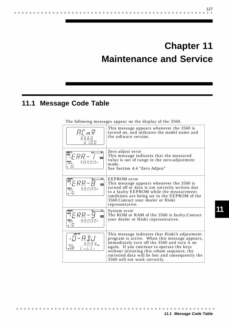
127
11.1 Message Code Table
1
2
3
4
5
6
7
8
9
10
11
12
13
14
15
This message appears whenever the 3560 isturned on, and indicates the model name andthe software version.
Zero adjust errorThis message indicates that the measuredvalue is out of range in the zero-adjustmentmode.See Section 4.4 "Zero Adjust"
EEPROM errorThis message appears whenever the 3560 isturned off or data is not correctly written dueto a faulty EEPROM while the measurementconditions are being set in the EEPROM of the3560.Contact your dealer or Hiokirepresentative.System errorThe ROM or RAM of the 3560 is faulty.Contactyour dealer or Hioki representative.
This message indicates that Hioki’s adjustmentprogram is active. When this message appears,immediately turn off the 3560 and turn it onagain. If you continue to operate the keyswithout initiating this reboot sequence, thecorrected data will be lost and consequently the3560 will not work correctly.
Chapter 11Maintenance and Service
11.1 Message Code Table
The following messages appear on the display of the 3560.
128
11.2 Cleaning
11.2 Cleaning
To clean the instrument, wipe it gently with a soft cloth moistened withwater or mild detergent. Never use solvents such as benzene, alcohol,acetone, ether, ketones, thinners or gasoline, as they can deform anddiscolor the case.

129
11.3 Troubleshooting
1
2
3
4
5
6
7
8
9
10
11
12
13
14
15
Symptom Cause Follow-up
Display is not lit whenthe powerswitch isturned on.
Power cord is not correctlyconnected.
Connect the power cord correctly.See section 3.2 " Connecting thePower Cord."
The power-supply voltage isnot consistent with the valueindicated on the 3560.
Use the power-supply voltageindicated by the 3560.
The measured value isnot displayed.Measurement valuesare wrong.
Leads are not correctlyconnected.
Connect leads correctly.
Leads are broken. Replace with a new cord.A measurement object havinga large reactance ismeasured.
Attempt to measure an objecthaving a small reactance.
Power supply frequency is notcorrectly set.
Set the power supply frequencycorrectly. See Section 3.5 "Settingthe Power Supply Frequency."
The preheating time is short. Ensure that sufficient preheatingtime is provided prior tomeasurement.See Section 3.4 "Powering On/Off."
ERR-8 is displayedcontinuously.
The EEPROM of the 3560 is faulty.See Section 11.1 "Message CodeTable."
The resistance/voltage rangeis not appropriate.
Select a range suitable for themeasurement object.See Section 4.2 "Setting theMeasurement Range."
The key operation isrejected.
Key lock is active. Cancel the key lock. See Section4.3.7 "Key Lock."
Remote mode is active. Cancel the remote mode.See Section 4.3.8 "Local."
Key lock can not becancelled.Remote can not becancelled.
LLO is executed by GP-IB. Execute GTL (go to local) by GP-IB.See Section 8.2 "OperatingProcedure (GP-IB)."
The external controlterminals (COMP0 toCOMP4) are selected.
Cancel selection of the externalcontrol terminals (COMP0 toCOMP4).See Section 6.3.1 "External ControlTerminal."
11.3 Troubleshooting
If damage is suspected, check the "Troubleshooting" section beforecontacting your dealer or Hioki representative.When sending the instrument for repair, pack carefully to preventdamage in transit. Include cushioning material so the instrument cannotmove within the package. Be sure to include details of the problem. Hiokicannot be responsible for damage that occurs during shipment.
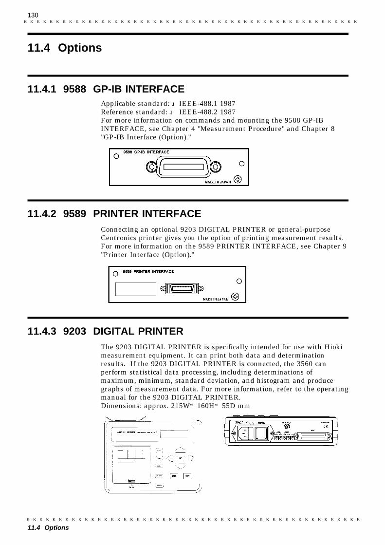
130
11.4 Options
11.4.1 9588 GP-IB INTERFACE
11.4.2 9589 PRINTER INTERFACE
11.4.3 9203 DIGITAL PRINTER
11.4 Options
Applicable standard: IEEE-488.1 1987Reference standard: IEEE-488.2 1987For more information on commands and mounting the 9588 GP-IBINTERFACE, see Chapter 4 "Measurement Procedure" and Chapter 8"GP-IB Interface (Option)."
Connecting an optional 9203 DIGITAL PRINTER or general-purposeCentronics printer gives you the option of printing measurement results.For more information on the 9589 PRINTER INTERFACE, see Chapter 9"Printer Interface (Option)."
The 9203 DIGITAL PRINTER is specifically intended for use with Hiokimeasurement equipment. It can print both data and determinationresults. If the 9203 DIGITAL PRINTER is connected, the 3560 canperform statistical data processing, including determinations ofmaximum, minimum, standard deviation, and histogram and producegraphs of measurement data. For more information, refer to the operatingmanual for the 9203 DIGITAL PRINTER.Dimensions: approx. 215W×160H×55D mm
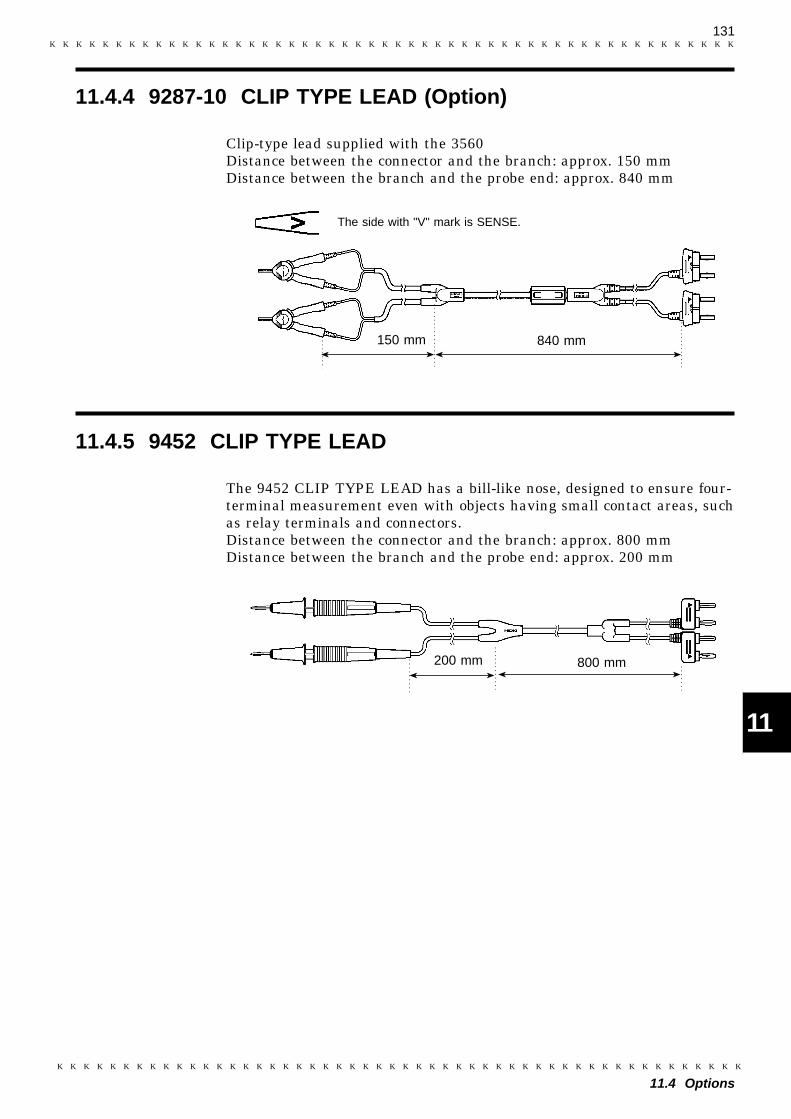
131
11.4 Options
1
2
3
4
5
6
7
8
9
10
11
12
13
14
15
11.4.4 9287-10 CLIP TYPE LEAD (Option)
150 mm 840 mm
The side with "V" mark is SENSE.
11.4.5 9452 CLIP TYPE LEAD
200 mm 800 mm
Clip-type lead supplied with the 3560Distance between the connector and the branch: approx. 150 mmDistance between the branch and the probe end: approx. 840 mm
The 9452 CLIP TYPE LEAD has a bill-like nose, designed to ensure four-terminal measurement even with objects having small contact areas, suchas relay terminals and connectors.Distance between the connector and the branch: approx. 800 mmDistance between the branch and the probe end: approx. 200 mm
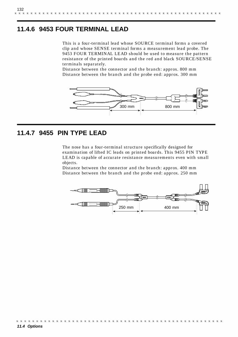
132
11.4 Options
11.4.6 9453 FOUR TERMINAL LEAD
300 mm 800 mm
11.4.7 9455 PIN TYPE LEAD
250 mm 400 mm
This is a four-terminal lead whose SOURCE terminal forms a coveredclip and whose SENSE terminal forms a measurement lead probe. The9453 FOUR TERMINAL LEAD should be used to measure the patternresistance of the printed boards and the red and black SOURCE/SENSEterminals separately.Distance between the connector and the branch: approx. 800 mmDistance between the branch and the probe end: approx. 300 mm
The nose has a four-terminal structure specifically designed forexamination of lifted IC leads on printed boards. This 9455 PIN TYPELEAD is capable of accurate resistance measurements even with smallobjects.Distance between the connector and the branch: approx. 400 mmDistance between the branch and the probe end: approx. 250 mm
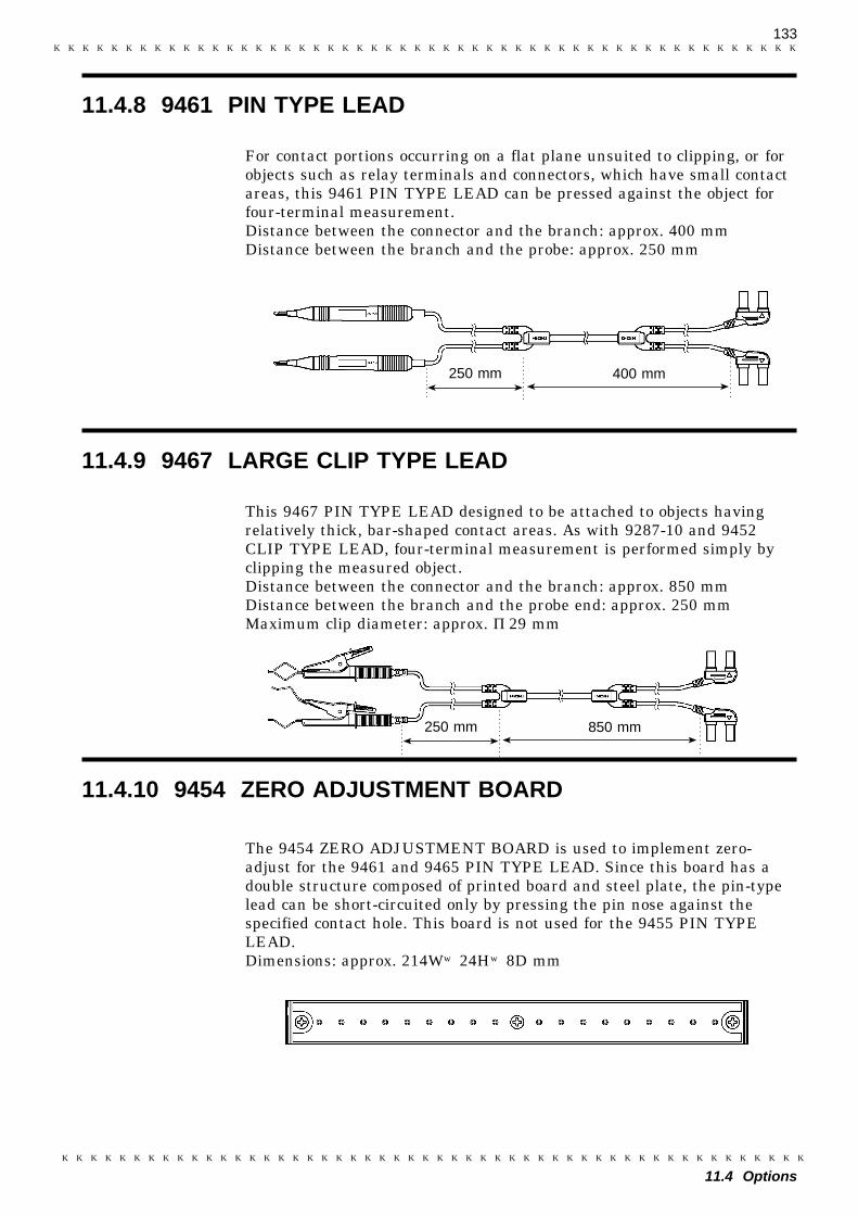
133
11.4 Options
11.4.8 9461 PIN TYPE LEAD
250 mm 400 mm
11.4.9 9467 LARGE CLIP TYPE LEAD
250 mm 850 mm
11.4.10 9454 ZERO ADJUSTMENT BOARD
For contact portions occurring on a flat plane unsuited to clipping, or forobjects such as relay terminals and connectors, which have small contactareas, this 9461 PIN TYPE LEAD can be pressed against the object forfour-terminal measurement.Distance between the connector and the branch: approx. 400 mmDistance between the branch and the probe: approx. 250 mm
This 9467 PIN TYPE LEAD designed to be attached to objects havingrelatively thick, bar-shaped contact areas. As with 9287-10 and 9452CLIP TYPE LEAD, four-terminal measurement is performed simply byclipping the measured object.Distance between the connector and the branch: approx. 850 mmDistance between the branch and the probe end: approx. 250 mmMaximum clip diameter: approx. φ29 mm
The 9454 ZERO ADJUSTMENT BOARD is used to implement zero-adjust for the 9461 and 9465 PIN TYPE LEAD. Since this board has adouble structure composed of printed board and steel plate, the pin-typelead can be short-circuited only by pressing the pin nose against thespecified contact hole. This board is not used for the 9455 PIN TYPELEAD.Dimensions: approx. 214W×24H×8D mm
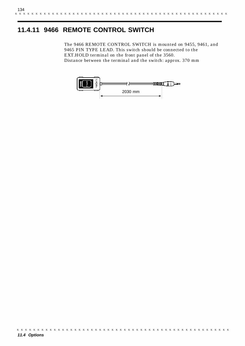
134
11.4 Options
11.4.11 9466 REMOTE CONTROL SWITCH
2030 mm
The 9466 REMOTE CONTROL SWITCH is mounted on 9455, 9461, and9465 PIN TYPE LEAD. This switch should be connected to theEXT.HOLD terminal on the front panel of the 3560.Distance between the terminal and the switch: approx. 370 mm
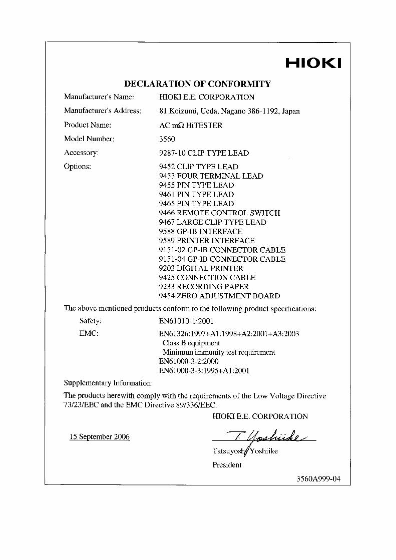


INSTRUCTION MANUALFor...は専用機種。複数の場合は「/」で区切る。不要の場合はとる。
形名を入力。 複数の場合は「/」で区切る。
3560品名を入力。
AC mΩ HiTESTER


HIOKI 3560 AC mΩ HiTESTERInstruction Manual
Publication date: September 2006 Revised edition 7
Edited and published by HIOKI E.E. CORPORATIONTechnical Support Section
All inquiries to International Sales and Marketing Department81 Koizumi, Ueda, Nagano, 386-1192, JapanTEL: +81-268-28-0562 / FAX: +81-268-28-0568E-mail: [email protected] http://www.hioki.co.jp/
Printed in Japan 3560A981-07
All reasonable care has been taken in the production of this manual, but if youfind any points which are unclear or in error, please contact your supplier orthe International Sales and Marketing Department at HIOKI headquarters.In the interests of product development, the contents of this manual are subjectto revision without prior notice.Unauthorized reproduction or copying of this manual is prohibited.

HEAD OFFICE81 Koizumi, Ueda, Nagano 386-1192, JapanTEL +81-268-28-0562 / FAX +81-268-28-0568E-mail: [email protected] / URL http://www.hioki.co.jp/HIOKI USA CORPORATION6 Corporate Drive, Cranbury, NJ 08512, USATEL +1-609-409-9109 / FAX +1-609-409-9108
3560A981-07 06-09H
Printed on recycled paper