load sharing option g3 - deif-cdn-umbraco.azureedge.net
TRANSCRIPT
DEIF A/S · Frisenborgvej 33 · DK-7800 Skive · Tel.: +45 9614 9614 · Fax: +45 9614 9615 · [email protected] · www.deif.com
DEIF A/S · Frisenborgvej 33 · DK-7800 Skive · Tel.: +45 9614 9614 · Fax: +45 9614 9615 · [email protected] · www.deif.com
DEIF A/S · Frisenborgvej 33 · DK-7800 Skive · Tel.: +45 9614 9614 · Fax: +45 9614 9615 · [email protected] · www.deif.com
MULTI-LINE 2DESCRIPTION OF OPTIONS
Option G3Load sharing
● Description of option● Functional description
Document no.: 4189340695ASW version:
1. Delimitation1.1. Scope of option G3.................................................................................................................................3
2. General information2.1. Warnings, legal information and safety..................................................................................................4
2.1.1. Warnings and notes ......................................................................................................................42.1.2. Legal information and disclaimer ..................................................................................................42.1.3. Safety issues ................................................................................................................................42.1.4. Electrostatic discharge awareness ...............................................................................................42.1.5. Factory settings ............................................................................................................................4
3. Description of option3.1. ANSI numbers........................................................................................................................................53.2. Option G3...............................................................................................................................................5
3.2.1. AGC...............................................................................................................................................53.3. Terminal description...............................................................................................................................5
4. Functional description4.1. Load sharing...........................................................................................................................................6
4.1.1. Working principle...........................................................................................................................64.2. Island ramp up with load steps...............................................................................................................84.3. Freeze power ramp................................................................................................................................84.4. External analogue setpoints...................................................................................................................94.5. Load sharing type...................................................................................................................................9
4.5.1. Load sharing modules.................................................................................................................104.5.2. Selco T4800 load sharer..............................................................................................................104.5.3. Cummins PCC 3100....................................................................................................................10
5. Parameters5.1. Further information ..............................................................................................................................13
Option G3, 4189340695 UK
DEIF A/S Page 2 of 13
1. Delimitation1.1 Scope of option G3
This description of options covers the following product:
AGC-3 SW version 3.4x.x or later
AGC-4 SW version 4.0x.x or later
Option G3, 4189340695 UK Delimitation
DEIF A/S Page 3 of 13

2. General information2.1 Warnings, legal information and safety
2.1.1 Warnings and notesThroughout this document, a number of warnings and notes with helpful user information will be presented.To ensure that these are noticed, they will be highlighted as follows in order to separate them from the gener-al text.
Warnings
Warnings indicate a potentially dangerous situation, which could result in death, personal in-jury or damaged equipment, if certain guidelines are not followed.
Notes
Notes provide general information, which will be helpful for the reader to bear in mind.
2.1.2 Legal information and disclaimerDEIF takes no responsibility for installation or operation of the generator set. If there is any doubt about howto install or operate the engine/generator controlled by the Multi-line 2 unit, the company responsible for theinstallation or the operation of the set must be contacted.
The Multi-line 2 unit is not to be opened by unauthorised personnel. If opened anyway, the war-ranty will be lost.
DisclaimerDEIF A/S reserves the right to change any of the contents of this document without prior notice.
2.1.3 Safety issuesInstalling and operating the Multi-line 2 unit may imply work with dangerous currents and voltages. Therefore,the installation should only be carried out by authorised personnel who understand the risks involved in work-ing with live electrical equipment.
Be aware of the hazardous live currents and voltages. Do not touch any AC measurement in-puts as this could lead to injury or death.
2.1.4 Electrostatic discharge awarenessSufficient care must be taken to protect the terminal against static discharges during the installation. Once theunit is installed and connected, these precautions are no longer necessary.
2.1.5 Factory settingsThe Multi-line 2 unit is delivered from factory with certain factory settings. These are based on average valuesand are not necessarily the correct settings for matching the engine/generator set in question. Precautionsmust be taken to check the settings before running the engine/generator set.
Option G3, 4189340695 UK General information
DEIF A/S Page 4 of 13

3. Description of option3.1 ANSI numbers
Function ANSI no.
Load sharing between gensets 90
3.2 Option G3
3.2.1 AGCOption G3 is a hardware option, and therefore a separate PCB is installed in slot #3 in addition to the stand-ard-installed hardware. If option M12 is already installed in the unit, option G3 is a software upgrade.
3.3 Terminal description
Term. Function Technical data Description Comment
37 -5/+5V DC Analogue I/O Active load sharing line Requires option G3
38 Com. Common Common
39 -5/+5V DC Analogue I/O Reactive load sharing Requires option D1/G3
40 -10/+10V DC Analogue I/O f/P setpoint Requires option G3
41 Com. Common Common
42 -10/+10V DC Analogue I/O U/Q setpoint Requires option D1/G3
Option G3, 4189340695 UK Description of option
DEIF A/S Page 5 of 13

4. Functional description4.1 Load sharing
Option G3 is an option that enables the unit to share the active load (and reactive load (option D1)) equally inpercentage of the nominal power. The load sharing is active when the genset is running in island mode andthe generator breaker is closed.
A voltage signal equal to the load produced by the genset is sent to the load sharing line. When the generatorload is 0%, 0V DC is sent to the load share line. When the load is 100%, the voltage will be 4V DC.
This is illustrated in the drawing below.Load sharing line
4V DC
100% loadReverse power
V DC
100% load
-4V DC
Power
The active load sharing line is illustrated above, and the characteristics of the reactive load sharing line areequivalent to it.
4.1.1 Working principleThe controller unit will supply a voltage on the load sharing line equal to the actual load. This voltage comesfrom an internal power transducer. At the same time, the actual voltage on the load sharing line will be meas-ured.
If the measured voltage is higher than the voltage from the internal power transducer, the unit will in-crease its load in order to match the voltage on the load sharing line.If the measured voltage is lower than the voltage from the internal power transducer, the unit will de-crease its load in order to match the voltage on the load sharing line.
The voltage on the load sharing line will only be different from the voltage from the internal power transducer,if two or more controller units are connected to the load share line.
Option G3, 4189340695 UK Functional description
DEIF A/S Page 6 of 13
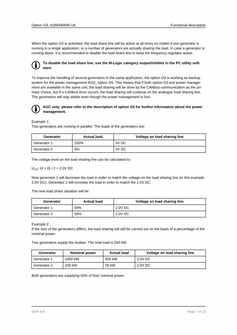
When the option G3 is activated, the load share line will be active at all times no matter if one generator isrunning in a single application, or a number of generators are actually sharing the load. In case a generator isrunning alone, it is recommended to disable the load share line to keep the frequency regulator active.
To disable the load share line, use the M-Logic category output/inhibits in the PC utility soft-ware.
To improve the handling of several generators in the same application, the option G3 is working as backupsystem for the power management AGC; option G5. This means that if both option G3 and power manage-ment are available in the same unit, the load sharing will be done by the CANbus communication as the pri-mary choice, but if a CANbus error occurs, the load sharing will continue on the analogue load sharing line.The generators will stay stable even though the power management is lost.
AGC only: please refer to the description of option G5 for further information about the powermanagement.
Example 1:Two generators are running in parallel. The loads of the generators are:
Generator Actual load Voltage on load sharing line
Generator 1 100% 4V DC
Generator 2 0% 0V DC
The voltage level on the load sharing line can be calculated to:
ULS: (4 + 0) / 2 = 2.0V DC
Now generator 1 will decrease the load in order to match the voltage on the load sharing line (in this example2.0V DC). Generator 2 will increase the load in order to match the 2.0V DC.
The new load share situation will be:
Generator Actual load Voltage on load sharing line
Generator 1 50% 2.0V DC
Generator 2 50% 2.0V DC
Example 2:If the size of the generators differs, the load sharing will still be carried out on the basis of a percentage of thenominal power.
Two generators supply the busbar. The total load is 550 kW.
Generator Nominal power Actual load Voltage on load sharing line
Generator 1 1000 kW 500 kW 2.0V DC
Generator 2 100 kW 50 kW 2.0V DC
Both generators are supplying 50% of their nominal power.
Option G3, 4189340695 UK Functional description
DEIF A/S Page 7 of 13

4.2 Island ramp up with load steps
Po
we
r [k
Wh
]
Time [sec] GB closed
De
lay,
ste
p 1
Power ramp [%/s]
Analogue load share set point
Ra
mp
up
, re
ad
fro
m lo
ad
sh
are
line Sta
nd
ard
lo
ad
sh
arin
g
One step before the
load share setpoint is
reached the ramp up
function is switched off
De
lay,
ste
p 2
De
lay,
ste
p 3
De
lay,
ste
p 4
De
lay,
ste
p 5
When menu 2614 is enabled, the power setpoint continues to rise in ramp up steps, determined by menu2615, towards the load sharing setpoint. The delay time between each ramp up step will be determined bymenu 2613. The ramp up will continue until the load sharing setpoint is reached, and then the regulator willbe switched to standard load sharing mode.
If the delay point is set to 20% and the number of load steps is set to 3, the genset will ramp to 20%, wait theconfigured delay time, ramp to 40%, wait, ramp to 60%, wait and then ramp to the system setpoint. If thesetpoint is at 50%, the ramp will stop at 50%.
4.3 Freeze power ramp
A way to define the ramp up steps is to use the freeze power ramp command in M-Logic.
Freeze power ramp active:
1. The power ramp will stop at any point of the power ramp, and this setpoint will be maintained as long asthe function is active.
2. If the function is activated while ramping from one delay point to another, the ramp will be fixed until thefunction is deactivated again.
3. If the function is activated while the delay timer is timing out, the timer will be stopped and will not contin-ue until the function is deactivated again.
Option G3, 4189340695 UK Functional description
DEIF A/S Page 8 of 13

4.4 External analogue setpoints
The genset can be controlled from internal as well as from external set points. The external set points areactivated with a digital input.
The inputs are only available, if option G3 is selected.
Five different inputs can be selected by using the ML-2 PC utility software (USW):
Input Ext. setpoint active condition Comment
Ext. frequency ctrl Stand-alone generator or GB opened
Ext. power ctrl Parallel to mains (AGC)
Ext. voltage ctrl Stand-alone generator or GB opened Requires option D1.
Ext. PF ctrl Parallel to mains (AGC)
Ext. VAr ctrl Parallel to mains (AGC)
The controller setpoints will be ignored if the running condition is not present. It is for instance not possible touse the frequency controller when paralleling to the mains.
The table below shows the possible setpoints.
Controller Input voltage Description Comment
Frequency +/-10V DC fNOM +/-10% AGC only: active when MB isOFF
Power +/-10V DC PNOM +/-100%
Voltage +/-10V DC UNOM +/-10% AGC only: active when GB isOFF
Reactive power +/-10V DC QNOM +/-100%
Power factor ÷10 V…0…10V DC 0.6 capacitive…1.0…0.6 inductive
The external setpoints can be used in all genset modes, when auto or semi-auto mode is selected.
Only a limited number of digital inputs are available in the standard unit. The unit should beinstalled with the sufficient number of options to get the desired digital inputs.
If the option H2 (Modbus RS 485 RTU) is available in the unit, the external setpoints can becontrolled from the control registers in the Modbus protocol. Please refer to the description ofoption H2 for further information.
4.5 Load sharing type
The AGC can be adjusted to work with different types of load sharing modules and ranges of the load sharingsignal. This is controlled by two menus: menu 6380 (signal level) and 6390 (load sharing type). The signallevel is used to adjust the maximum output of the LS lines. The default range is 0-4V DC, and therefore 4VDC is the voltage applied to the load sharing line at 100% load. If the AGC is interfacing to another productwhere the max. range is different, then it can be changed in this menu.
Option G3, 4189340695 UK Functional description
DEIF A/S Page 9 of 13

To be able to adjust the max. range, it is necessary to adjust the menu 6391 to "adjustable". The AGC is ableto provide between 1.0 and 5.0V DC as 100% load. Load sharing interfacing to DEIF Uni-line LSU (load shar-ing unit) and Multi-line 2 version 1 and version 2 might require a 0-5V DC range, depending on configuration.If the load sharing is unequal, please check this.
Menu 6390 holds the following possibilities:● Adjustable● Selco T4800● Cummins PCC
When either "Selco T4800" or "Cummins PCC" is selected, then the adjustable range is ignored. The selec-tion causes the AGC to modify the signal level of the LS lines to adapt to the specific brand of controller/loadshare unit.
4.5.1 Load sharing modulesIf interfacing is performed to the load sharing modules of unspecified brands, it might be necessary to providegalvanic separation of the load sharing lines. The input impedance of such isolation amplifiers should be highimpedance for proper function.
4.5.2 Selco T4800 load sharerThe signal level is +/-1V DC, so the AGC adapts automatically to this level. The terminals of the T4800 are 12(com) and 13 (+). When interfacing to the Selco T4800, the frequency difference of the measured comparedto generator nominal is taken into account in order to prevent unequal load sharing (not user-configurable).T4800 is for kW sharing only and not kVAr sharing.
4.5.3 Cummins PCC 3100The signal level is 0.3-2.1V DC, so the AGC adapts automatically to this level. The terminals (TB3) of thePCC3100 are placed on connector 8, and the terminals are 51 (kW), 53 (kVAr), 52 and 54 (common). Termi-nal 55 is a dedicated terminal for the shield of the load sharing cable. (Notice that kVAr sharing is option-dependent in some DEIF products (option D1)).
Cummins PCC applicationsWhen the DEIF AGC-3, AGC-4 or AGC 200/IOM230 is being used, then it is possible to interface directly withthe PCC using the terminal numbers as mentioned above.
Option G3, 4189340695 UK Functional description
DEIF A/S Page 10 of 13

PCC interface to DEIF AGC
PCC Interface to AGC-200/IOM-230
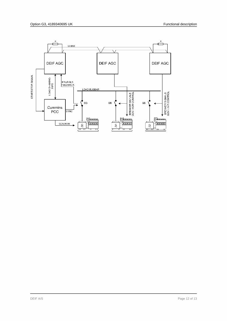
PCC in DEIF power management systemNotice that if the AGC is part of a power management system, then it is possible to enable the analogue loadsharing lines. This is done in M-logic by activating the command "Use Ana LS instead of CAN". If the CANbuscommunication is used for load sharing, the analogue LS line of the AGC-3 and AGC-4 is still updated so theCummins PCC will be able to adjust the load level according to the load level of the AGCs. This is useful ifthe AGC is placed on all gensets only sending start and stop commands to the PCC. This means that theCummins ILSI unit is not necessary.
Option G3, 4189340695 UK Functional description
DEIF A/S Page 11 of 13
Option G3, 4189340695 UK Functional description
DEIF A/S Page 12 of 13

5. Parameters5.1 Further information
The option G3 relates to the parameters 2610 and 6380-6390.
For further information, please see the separate parameter list for the Multi-line unit in question:
AGC-3 Document number 4189340705
AGC-4 Document number 4189340688
Option G3, 4189340695 UK Parameters
DEIF A/S Page 13 of 13